Embed Size (px)
Citation preview
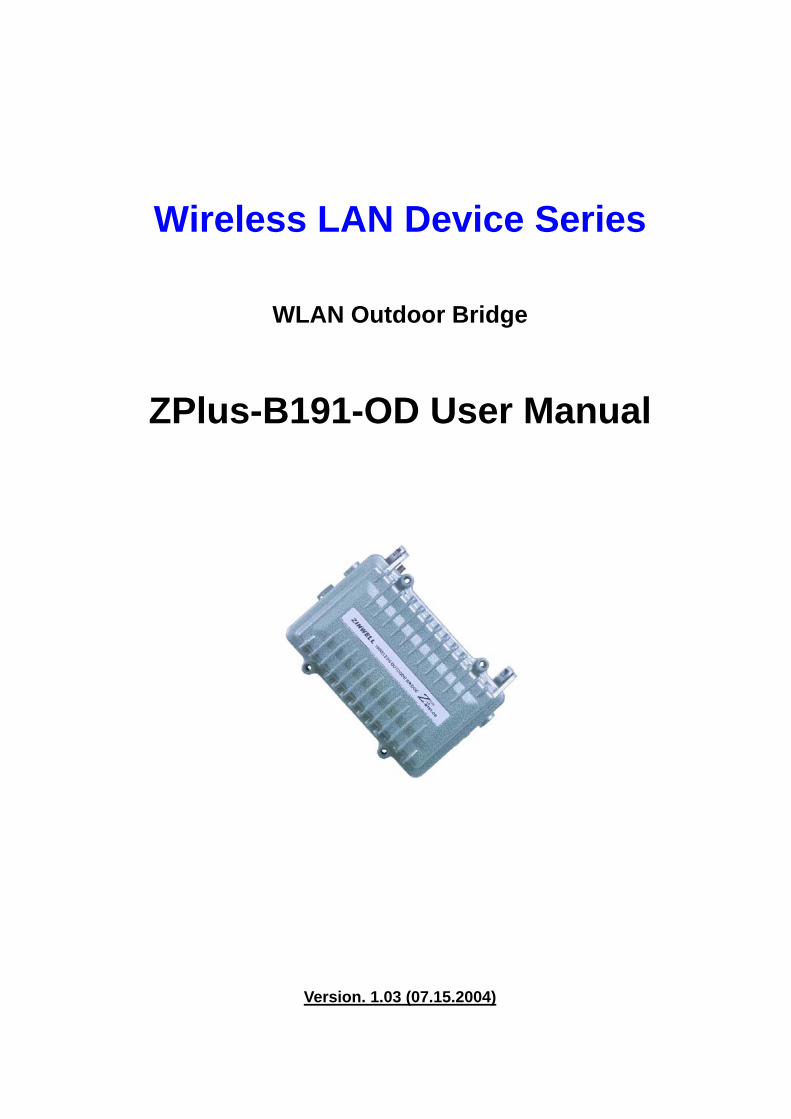
Wireless LAN Device Series
WLAN Outdoor Bridge
ZPlus-B191-OD User Manual
Version. 1.03 (07.15.2004)
1
Notice
“This device complies with Part 15 of the FCC Rules. Operation is subject to the following two conditions: (1) This device may not cause harmful interference, and (2) this device must
accept any interference received, including interference that may cause undesired operation. Warning: Changes or modifications to this unit not expressly approved by the party responsible
for compliance could void the user authority to operate the equipment. This device complies with Part 15 of the FCC Rules. Operation is subject to the following two conditions: (1) This device may not cause harmful interference, and (2) this device must
accept any interference received, including interference that may cause undesired operation. The user’s manual or instruction manual for an intentional or unintentional radiator shall caution the user that changes or modifications not expressly ODU proved by the party responsible for compliance could void the user’s authority to operate the equipment. NOTE: This equipment has been tested and found to comply with the limits for a Class B digital
device, pursuant to Part 15 of the FCC Rules. These limits are designed to provide reasonable protection against harmful interference in a residential installation. This equipment generates uses and can radiate radio frequency energy and, if not installed and used in accordance with the instructions, may cause harmful interference to radio communications. However, there is no guarantee that interference will not occur in a particular installation. If this equipment does cause harmful interference to radio or television reception, which can be determined by turning the equipment off and on, the user is encouraged to try to correct the interference by one or more of the following measures:
Reorient or relocate the receiving antenna. Increase the separation between the equipment and receiver. Connect the equipment into an outlet on a circuit different from that to which the receiver
is needed. Consult the dealer or an experienced radio/TV technician for help.
Changes or modifications not expressly ODU proved by the party responsible for compliance could void the user‘s authority to operate the equipment. The antenna(s) used for this transmitter must not be co-located or operating in conjunction with any other antenna or transmitter
Shielded interface cables must be used in order to comply with emission limits.
This EUT is incompliance with SAR for general population /uncontrolled exposure limits in ANSI/IEEE C95.1-1999 and had been tested in accordance with the measurement methods and procedures specified in OET Bulletin 65 Supplement C This device and its antenna(s) must not be co-located or operating in conjunction with any other antenna or transmitter
CAUTION:
1. The antenna(s) used for this transmitter must be fixed-mounted on outdoor permanent structures with a separation distance of at least 2 meters from all persons and must not be co-located or operating in conjunction with any other antenna or transmitter. Users and installers must be provided with antenna installation instructions and transmitter operating conditions for satisfying RF exposure compliance.
2. This Transmitter must not be co-located or operating in conjunction with any other
antenna or transmitter.
3. This equipment is only allowed to be professionally installed.
2

3
Contents 1 INTRODUCTION.................................................................................................................................................. 4 2 HARDWARE INSTALLATION ............................................................................................................................ 5
2.1 PACKING LIST ................................................................................................................................................ 5 2.2 HARDWARE INSTALLATION ............................................................................................................................ 6
3 SOFTWARE CONFIGURATION........................................................................................................................ 10 3.1 ENTER WEB CONFIGURATION PAGE............................................................................................................... 10 3.2 STATUS OF WLAN OUTDOOR BRIDGE......................................................................................................... 10 3.3 WIRELESS LAN SETTING............................................................................................................................. 12
3.3.1 Basic settings.......................................................................................................................................... 12 3.3.2 Wireless Advanced Settings .................................................................................................................... 15 3.3.3 Wireless Security setup ........................................................................................................................... 17 3.3.3.1 WEP Encryption Setting .................................................................................................................... 17 3.3.3.2 WEP Encryption with 802.1x Setting................................................................................................. 19 3.3.3.3 WPA Encryption Setting..................................................................................................................... 20 3.3.4 Wireless Access Control ......................................................................................................................... 21 3.3.5 Wireless Site Survey................................................................................................................................ 23 3.3.6 WDS Settings .......................................................................................................................................... 24
3.4 LAN INTERFACE SETUP............................................................................................................................... 26 3.4.1 Using the Fixed IP.................................................................................................................................. 26 3.4.2 Using DHCP Client................................................................................................................................ 28 3.4.3 Enable DHCP Server ............................................................................................................................. 29
3.5 WLAN AP STATISTICS ................................................................................................................................ 30 3.6 UPGRADE FIRMWARE................................................................................................................................... 31 3.7 SAVE/RELOAD SETTINGS ............................................................................................................................. 31 3.8 SETUP PASSWORD ........................................................................................................................................ 32
4 WIRELESS CONNECTION ARCHITECTURE................................................................................................. 34 4.1 INFRASTRUCTURE MODE .............................................................................................................................. 34 4.2 AD-HOC MODE............................................................................................................................................. 34 4.3 WIRELESS AP FUNCTIONS ........................................................................................................................... 35
4.3.1 Access Point Mode ................................................................................................................................. 35 4.3.2 Access Point Client Mode (Ad-Hoc)....................................................................................................... 36 4.3.3 Access Point Client Mode (Infrastructure)............................................................................................. 36 4.3.4 Wireless Repeater ................................................................................................................................... 37 4.3.5 WDS (Wireless Distribution System) ...................................................................................................... 37 4.3.6 Wireless Bridge....................................................................................................................................... 38
4.4 SELECTING AN APPROPRIATE SITE ................................................................................................................ 39 4.5 POWER OVER ETHERNET.............................................................................................................................. 39
4
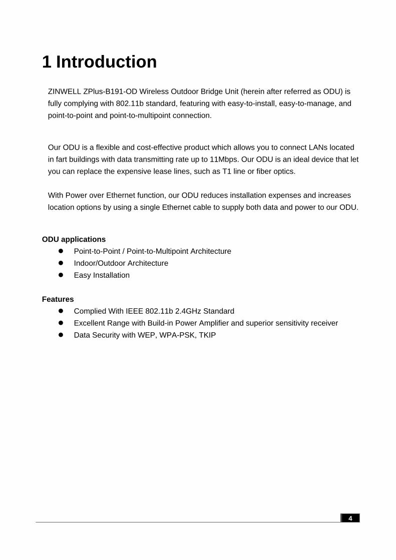
1 Introduction ZINWELL ZPlus-B191-OD Wireless Outdoor Bridge Unit (herein after referred as ODU) is fully complying with 802.11b standard, featuring with easy-to-install, easy-to-manage, and point-to-point and point-to-multipoint connection.
Our ODU is a flexible and cost-effective product which allows you to connect LANs located in fart buildings with data transmitting rate up to 11Mbps. Our ODU is an ideal device that let you can replace the expensive lease lines, such as T1 line or fiber optics. With Power over Ethernet function, our ODU reduces installation expenses and increases location options by using a single Ethernet cable to supply both data and power to our ODU.
ODU applications Point-to-Point / Point-to-Multipoint Architecture Indoor/Outdoor Architecture Easy Installation
Features
Complied With IEEE 802.11b 2.4GHz Standard Excellent Range with Build-in Power Amplifier and superior sensitivity receiver Data Security with WEP, WPA-PSK, TKIP
2 Hardware Installation This Chapter helps you to install the hardware in a quick and easy way.
2.1 Packing List
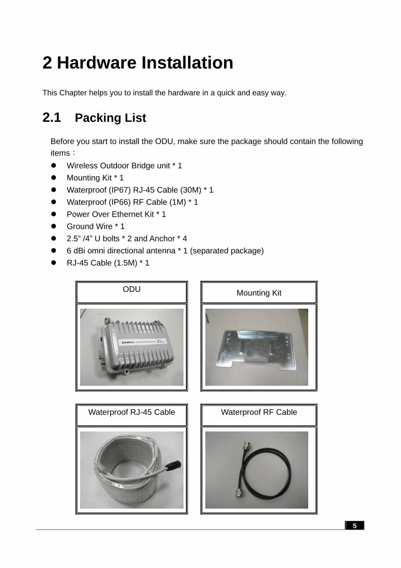
Before you start to install the ODU, make sure the package should contain the following items: Wireless Outdoor Bridge unit * 1 Mounting Kit * 1 Waterproof (IP67) RJ-45 Cable (30M) * 1 Waterproof (IP66) RF Cable (1M) * 1 Power Over Ethernet Kit * 1 Ground Wire * 1 2.5” /4” U bolts * 2 and Anchor * 4 6 dBi omni directional antenna * 1 (separated package) RJ-45 Cable (1.5M) * 1
ODU Mounting Kit
Waterproof RJ-45 Cable Waterproof RF Cable
5

Power Over Ethernet Kit Ground Wire
RJ-45 Cable 6 dBi omni directional antenna
2.5” /4” U bolt and Anchor
2.2 Hardware Installation
Once you check off everything from the package, you can start to install the ODU. You can mount to a pipe, a pole or to the side of a building. The steps are showed in the following: 1. You must mount the ODU into the bracket first.
Note: ALL the 4 screws had been tightened onto the ODU and bracket 6
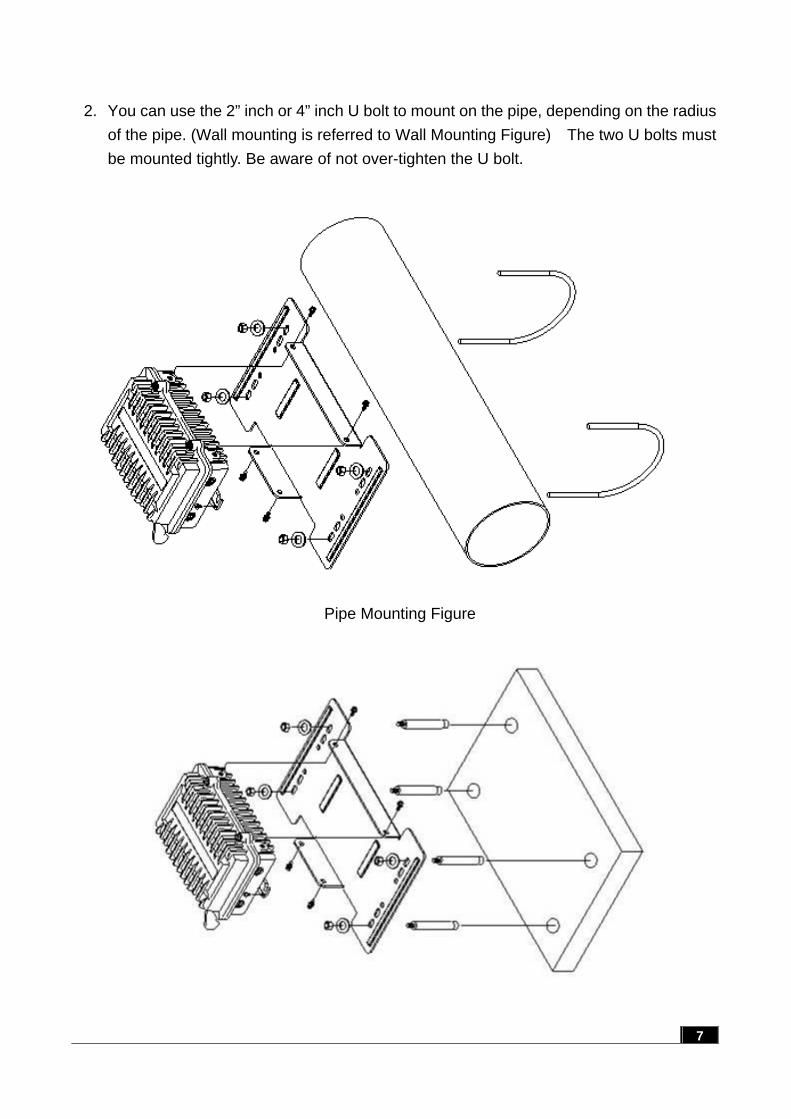
2. You can use the 2” inch or 4” inch U bolt to mount on the pipe, depending on the radius
of the pipe. (Wall mounting is referred to Wall Mounting Figure) The two U bolts must be mounted tightly. Be aware of not over-tighten the U bolt.
Pipe Mounting Figure
7
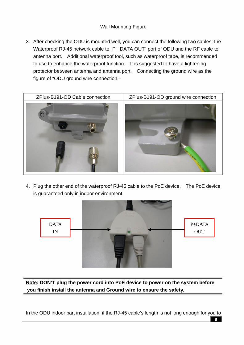
Wall Mounting Figure 3. After checking the ODU is mounted well, you can connect the following two cables: the
Waterproof RJ-45 network cable to “P+ DATA OUT” port of ODU and the RF cable to antenna port. Additional waterproof tool, such as waterproof tape, is recommended to use to enhance the waterproof function. It is suggested to have a lightening protector between antenna and antenna port. Connecting the ground wire as the figure of “ODU ground wire connection.”
ZPlus-B191-OD Cable connection ZPlus-B191-OD ground wire connection
4. Plug the other end of the waterproof RJ-45 cable to the PoE device. The PoE device
is guaranteed only in indoor environment.
Note: DON’T plug the power cord into PoE device to power on the system before you finish install the antenna and Ground wire to ensure the safety.
DATA IN
P+DATA OUT
In the ODU indoor part installation, if the RJ-45 cable’s length is not long enough for you to
8
link to your network device, you can extend the cable length. However, make sure the maximum length of the RJ-45 cable is 100M (about 109 yards) for normal operation under 802.3 standard. When you plug the regular RJ-45 cable into the PoE device, you should use the regular RJ-45 cable to plug into the “DATA IN” of “Power Over Ethernet Kit” to connect to hub/switch or use the crosslink Rj-45 cable (Not included in the Packing List) to connect with user’s PC. The waterproof RJ-45 cable must be connected to the “P+DATA OUT” port.
Note: Be careful! Don’t plug the two cables inversely. It will damage the devices!
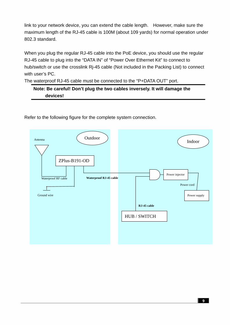
Refer to the following figure for the complete system connection.
9
Power injector
ZPlus-B191-OD
Waterproof RF cable
RJ-45 cable
Waterproof RJ-45 cable
Power cord
Indoor Outdoor
Power supply
HUB / SWITCH
Antenna
Ground wire
10
3 Software Configuration
3.1 Enter web configuration page
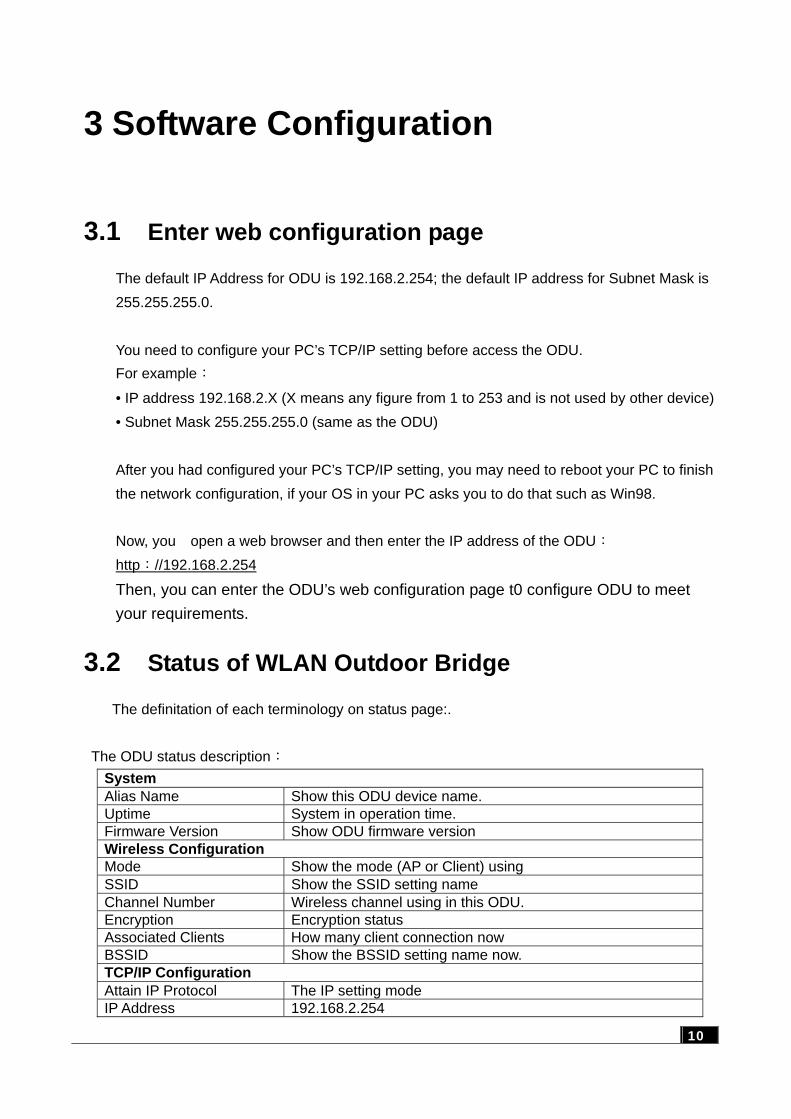
The default IP Address for ODU is 192.168.2.254; the default IP address for Subnet Mask is 255.255.255.0. You need to configure your PC’s TCP/IP setting before access the ODU. For example:
• IP address 192.168.2.X (X means any figure from 1 to 253 and is not used by other device) • Subnet Mask 255.255.255.0 (same as the ODU) After you had configured your PC’s TCP/IP setting, you may need to reboot your PC to finish the network configuration, if your OS in your PC asks you to do that such as Win98. Now, you open a web browser and then enter the IP address of the ODU: http://192.168.2.254
Then, you can enter the ODU’s web configuration page t0 configure ODU to meet your requirements.
3.2 Status of WLAN Outdoor Bridge
The definitation of each terminology on status page:.
The ODU status description: System Alias Name Show this ODU device name. Uptime System in operation time. Firmware Version Show ODU firmware version Wireless Configuration Mode Show the mode (AP or Client) using SSID Show the SSID setting name Channel Number Wireless channel using in this ODU. Encryption Encryption status Associated Clients How many client connection now BSSID Show the BSSID setting name now. TCP/IP Configuration Attain IP Protocol The IP setting mode IP Address 192.168.2.254
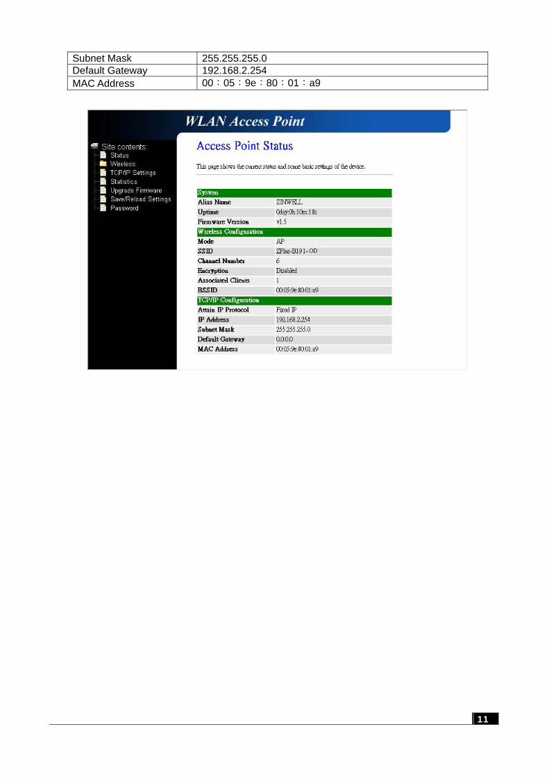
Subnet Mask 255.255.255.0 Default Gateway 192.168.2.254 MAC Address 00:05:9e:80:01:a9
11
3.3 Wireless LAN Setting
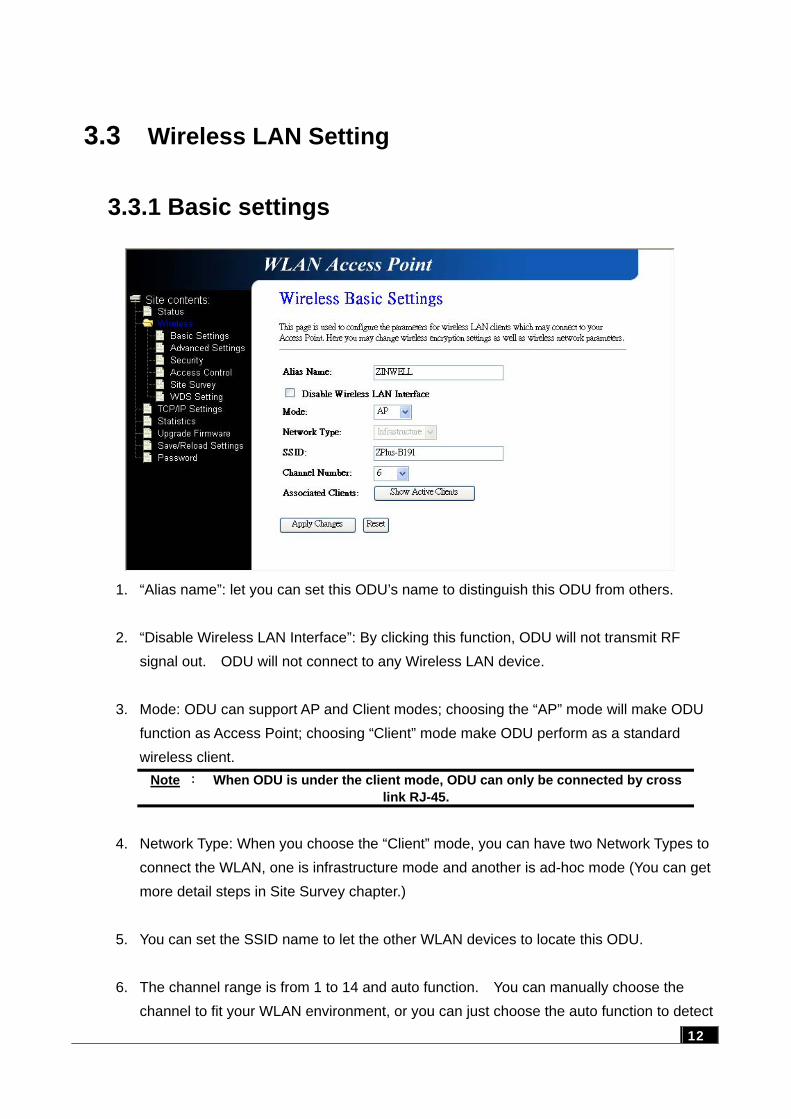
3.3.1 Basic settings
1. “Alias name”: let you can set this ODU’s name to distinguish this ODU from others. 2. “Disable Wireless LAN Interface”: By clicking this function, ODU will not transmit RF
signal out. ODU will not connect to any Wireless LAN device. 3. Mode: ODU can support AP and Client modes; choosing the “AP” mode will make ODU
function as Access Point; choosing “Client” mode make ODU perform as a standard wireless client.
Note : When ODU is under the client mode, ODU can only be connected by cross link RJ-45.
4. Network Type: When you choose the “Client” mode, you can have two Network Types to
connect the WLAN, one is infrastructure mode and another is ad-hoc mode (You can get more detail steps in Site Survey chapter.)
5. You can set the SSID name to let the other WLAN devices to locate this ODU. 6. The channel range is from 1 to 14 and auto function. You can manually choose the
channel to fit your WLAN environment, or you can just choose the auto function to detect 12
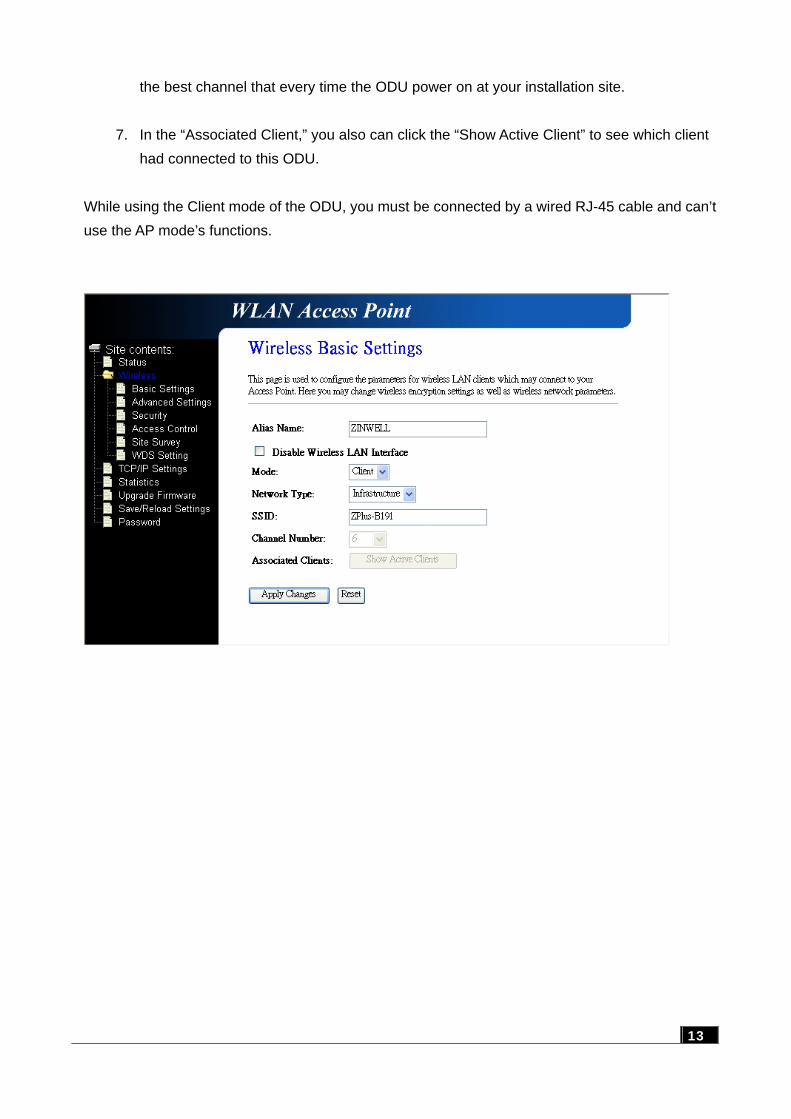
the best channel that every time the ODU power on at your installation site. 7. In the “Associated Client,” you also can click the “Show Active Client” to see which client
had connected to this ODU.
While using the Client mode of the ODU, you must be connected by a wired RJ-45 cable and can’t use the AP mode’s functions.
13
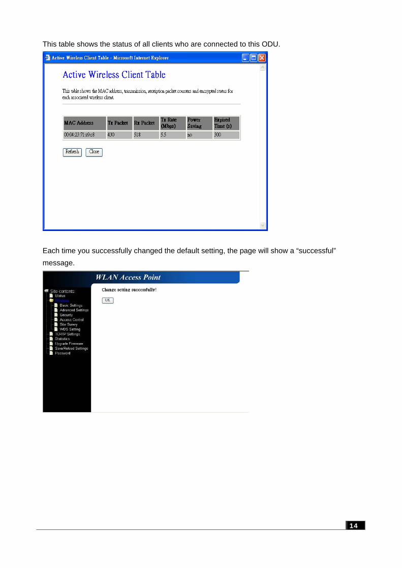
This table shows the status of all clients who are connected to this ODU.
Each time you successfully changed the default setting, the page will show a “successful” message.
14
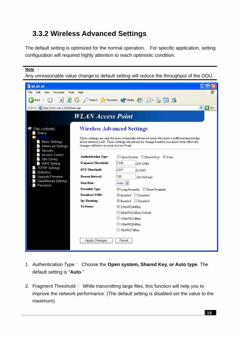
3.3.2 Wireless Advanced Settings
The default setting is optimized for the normal operation. For specific application, setting configuration will required highly attention to reach optimistic condition. Note : Any unreasonable value change to default setting will reduce the throughput of the ODU.
1. Authentication Type: Choose the Open system, Shared Key, or Auto type. The
default setting is “Auto.” 2. Fragment Threshold: While transmitting large files, this function will help you to
improve the network performance. (The default setting is disabled set the value to the maximum)
15
16
3. RTS Threshold: This function is designed to prevent the low throughput from the hidden node of WLAN device. The default setting is disabled (set the value to the maximum).
4. Beacon Interval: The interval time to send the beacon. The default value is 100ms. 5. Broadcast SSID: Broadcasting the SSID will let your client find the ODU automatically.
If you disable the function, you must connect the xx by manually write down the ODU’s SSID in your client setting.
6. Int. Roaming: This function will let users roam among ODUs. Users can have more
wireless working range. You should comply with the following instruction to ensure that you can roam among the wireless coverage areas. All the ODUs must be in the same subnet network and the SSID must be the
same. If you use the 802.1x authentication, you need to have the user profile in these
ODUs for the roaming station.
Tx Power: The output power you can adjust to follow different country regulations. Output Power Antenna gain
FCC Certification 200mW (default ) 6 dBi or 9 dBi
CE Certification 100mW (with Antenna)
6 dBi or 9 dBi
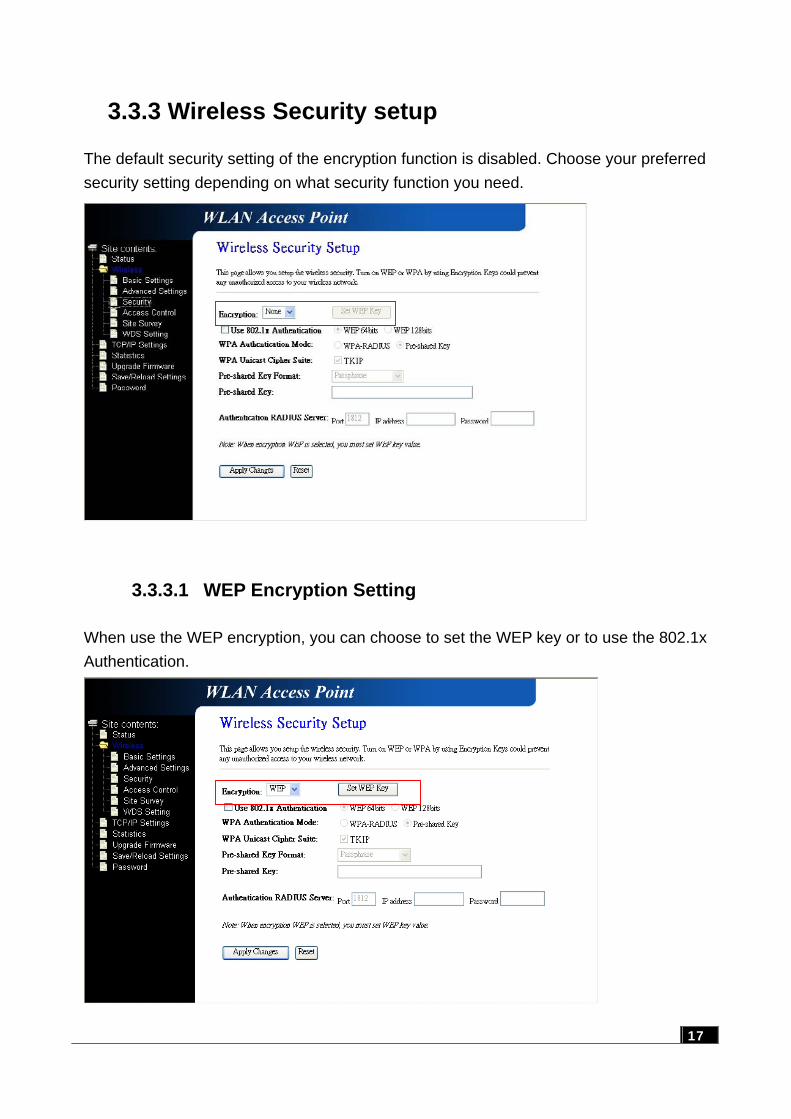
3.3.3 Wireless Security setup
The default security setting of the encryption function is disabled. Choose your preferred security setting depending on what security function you need.
17
3.3.3.1 WEP Encryption Setting
When use the WEP encryption, you can choose to set the WEP key or to use the 802.1x Authentication.
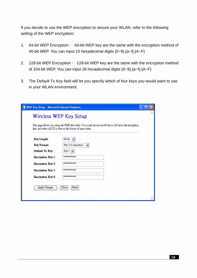
If you decide to use the WEP encryption to secure your WLAN, refer to the following setting of the WEP encryption: 1. 64-bit WEP Encryption: 64-bit WEP key are the same with the encryption method of
40-bit WEP. You can input 10 hexadecimal digits {0~9},{a~f},{A~F} 2. 128-bit WEP Encryption: 128-bit WEP key are the same with the encryption method
of 104-bit WEP. You can input 26 hexadecimal digits {0~9},{a~f},{A~F} 3. The Default Tx Key field will let you specify which of four keys you would want to use
in your WLAN environment.
18
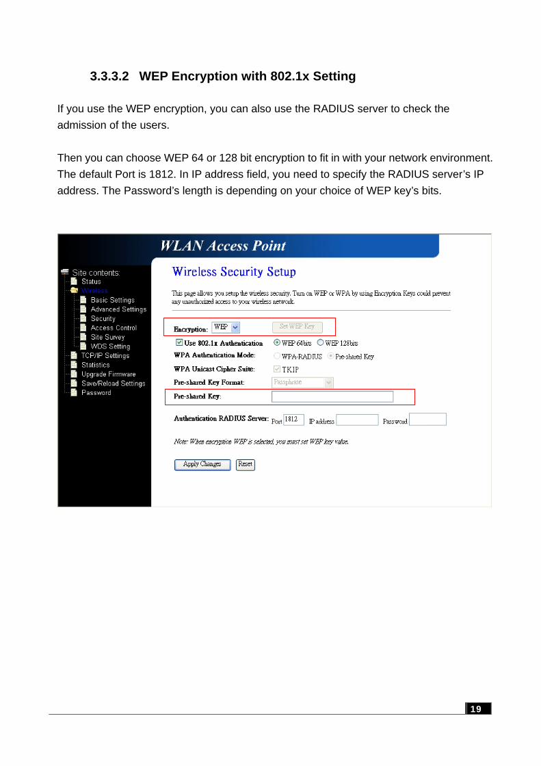
3.3.3.2 WEP Encryption with 802.1x Setting
If you use the WEP encryption, you can also use the RADIUS server to check the admission of the users. Then you can choose WEP 64 or 128 bit encryption to fit in with your network environment. The default Port is 1812. In IP address field, you need to specify the RADIUS server’s IP address. The Password’s length is depending on your choice of WEP key’s bits.
19
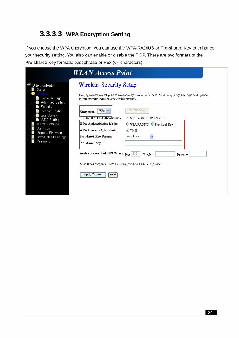
3.3.3.3 WPA Encryption Setting
If you choose the WPA encryption, you can use the WPA-RADIUS or Pre-shared Key to enhance your security setting. You also can enable or disable the TKIP. There are two formats of the Pre-shared Key formats: passphrase or Hex (64 characters).
20
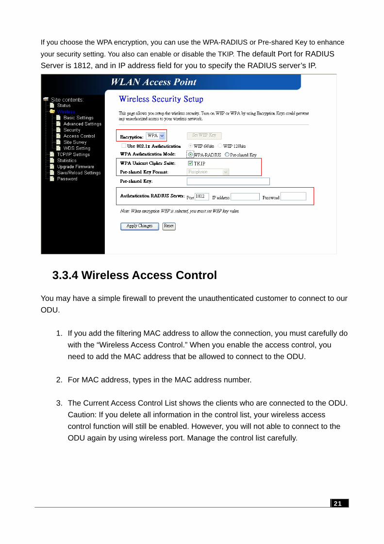
If you choose the WPA encryption, you can use the WPA-RADIUS or Pre-shared Key to enhance
your security setting. You also can enable or disable the TKIP. The default Port for RADIUS Server is 1812, and in IP address field for you to specify the RADIUS server’s IP.
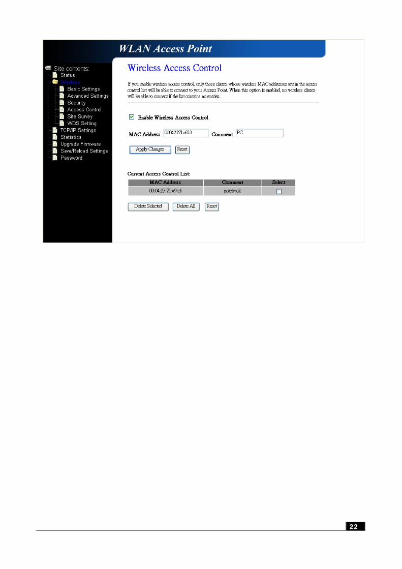
3.3.4 Wireless Access Control
You may have a simple firewall to prevent the unauthenticated customer to connect to our ODU.
1. If you add the filtering MAC address to allow the connection, you must carefully do with the “Wireless Access Control.” When you enable the access control, you need to add the MAC address that be allowed to connect to the ODU.
2. For MAC address, types in the MAC address number. 3. The Current Access Control List shows the clients who are connected to the ODU.
Caution: If you delete all information in the control list, your wireless access control function will still be enabled. However, you will not able to connect to the ODU again by using wireless port. Manage the control list carefully.
21
22
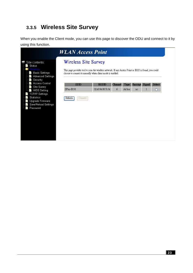
3.3.5 Wireless Site Survey
When you enable the Client mode, you can use this page to discover the ODU and connect to it by using this function.
23
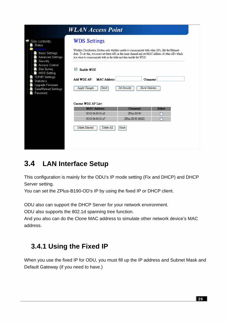
3.3.6 WDS Settings
WDS function includes Wireless Repeater Mode and Bridge Mode, which shown on 5.3.4 and 5.3.6. When you set up the WDS system, you should consider the following items: 1. ALL your ODU must have the same channel. 2. ALL The ODU and Clients devices must be at the same subnet network. 3. WDS connection scenario allows devices under WDS mode (WDS device) and Client
mode (Client device) to be connected. If you only want to allow WDS devices connecting to WDS network, you can enable the “Access control” function and don’t add any MAC address to the list. If you want to enhance the security, you can disable “Broadcast function after you had finished the WDS setting. (Please refer to Chapter 3.3.2 “Wireless Advanced Settings”)
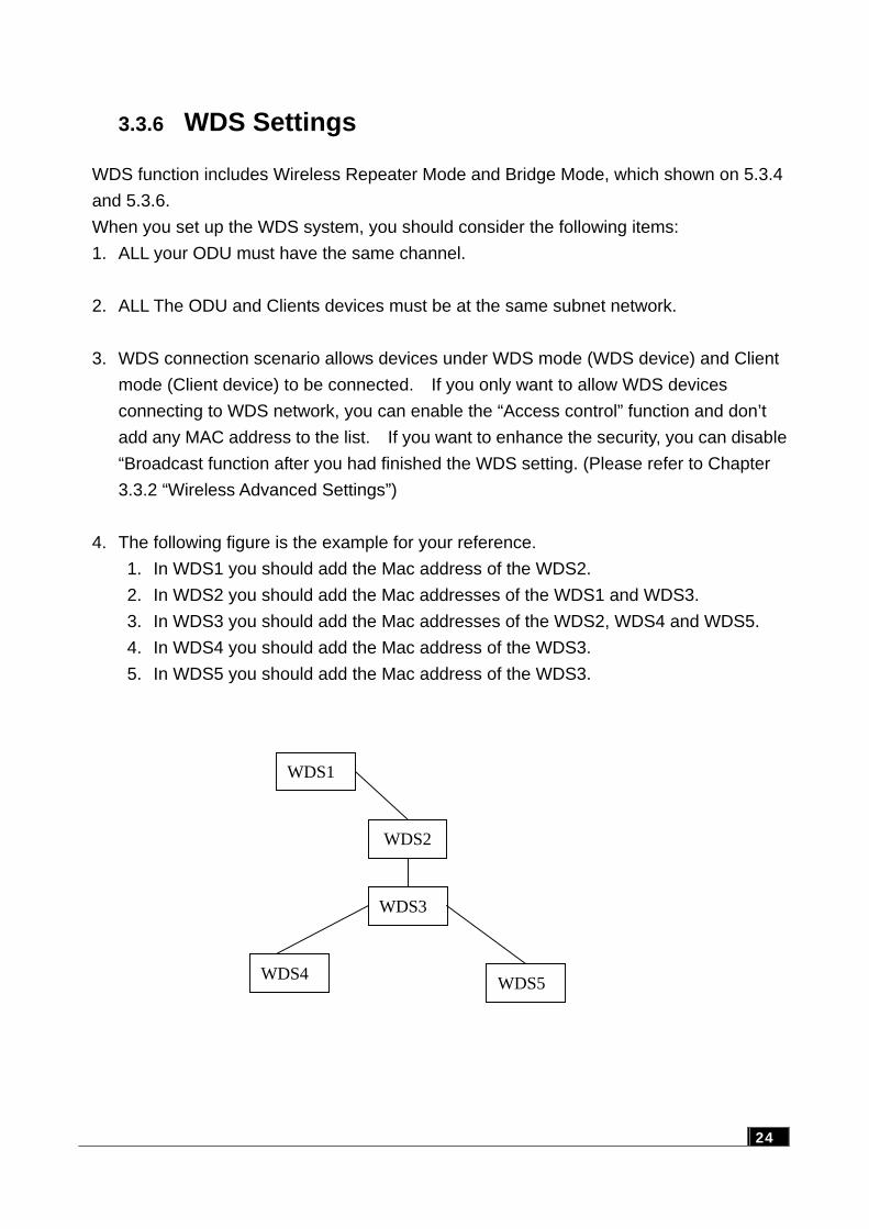
4. The following figure is the example for your reference.
1. In WDS1 you should add the Mac address of the WDS2. 2. In WDS2 you should add the Mac addresses of the WDS1 and WDS3. 3. In WDS3 you should add the Mac addresses of the WDS2, WDS4 and WDS5. 4. In WDS4 you should add the Mac address of the WDS3. 5. In WDS5 you should add the Mac address of the WDS3.
WDS1
WDS2
WDS3
WDS5 WDS4
24
3.4 LAN Interface Setup
This configuration is mainly for the ODU’s IP mode setting (Fix and DHCP) and DHCP Server setting. You can set the ZPlus-B190-OD’s IP by using the fixed IP or DHCP client. ODU also can support the DHCP Server for your network environment. ODU also supports the 802.1d spanning tree function. And you also can do the Clone MAC address to simulate other network device’s MAC address.
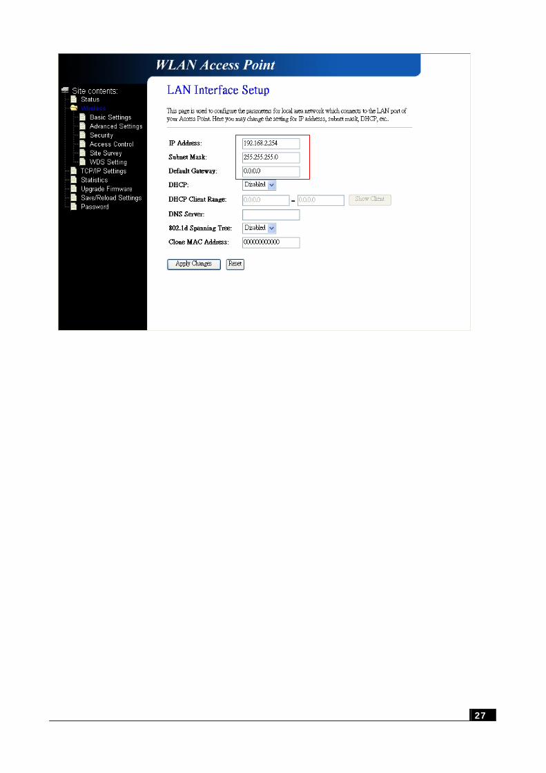
3.4.1 Using the Fixed IP
When you use the fixed IP for ODU, you must fill up the IP address and Subnet Mask and Default Gateway (if you need to have.)
26
27
27
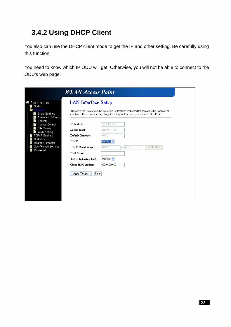
3.4.2 Using DHCP Client
You also can use the DHCP client mode to get the IP and other setting. Be carefully using this function. You need to know which IP ODU will get. Otherwise, you will not be able to connect to the ODU’s web page.
28
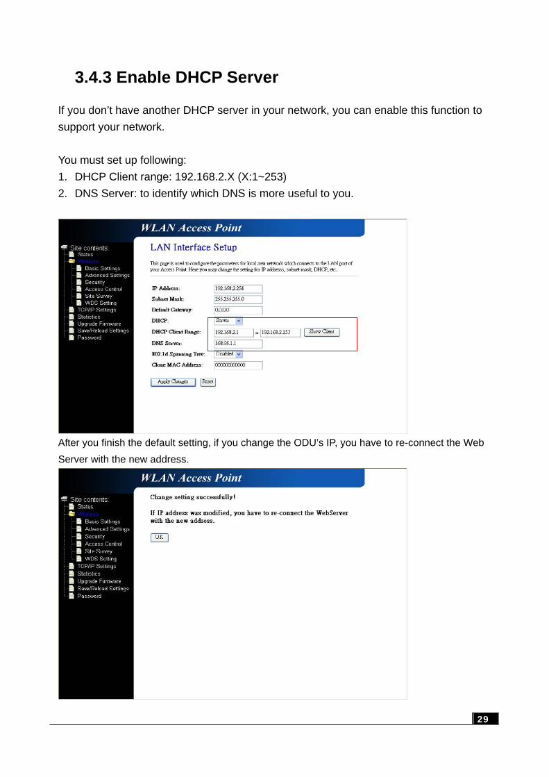
3.4.3 Enable DHCP Server
If you don’t have another DHCP server in your network, you can enable this function to support your network. You must set up following: 1. DHCP Client range: 192.168.2.X (X:1~253) 2. DNS Server: to identify which DNS is more useful to you.
After you finish the default setting, if you change the ODU’s IP, you have to re-connect the Web Server with the new address.
29
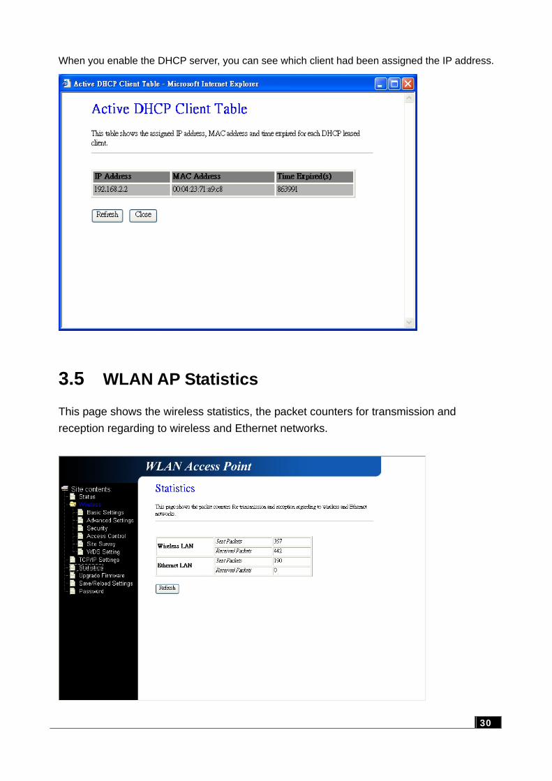
When you enable the DHCP server, you can see which client had been assigned the IP address.
3.5 WLAN AP Statistics
This page shows the wireless statistics, the packet counters for transmission and reception regarding to wireless and Ethernet networks.
30
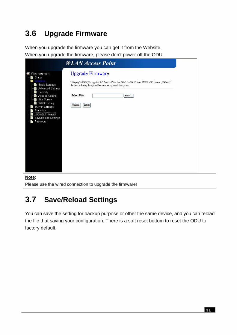
3.6 Upgrade Firmware
When you upgrade the firmware you can get it from the Website. When you upgrade the firmware, please don’t power off the ODU.
Note: Please use the wired connection to upgrade the firmware!
3.7 Save/Reload Settings
You can save the setting for backup purpose or other the same device, and you can reload the file that saving your configuration. There is a soft reset bottom to reset the ODU to factory default.
31
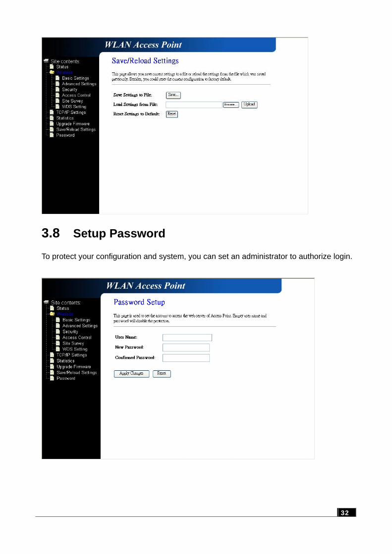
3.8 Setup Password
To protect your configuration and system, you can set an administrator to authorize login.
32
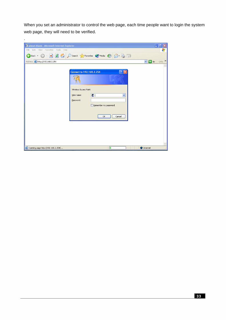
When you set an administrator to control the web page, each time people want to login the system
web page, they will need to be verified. .
33
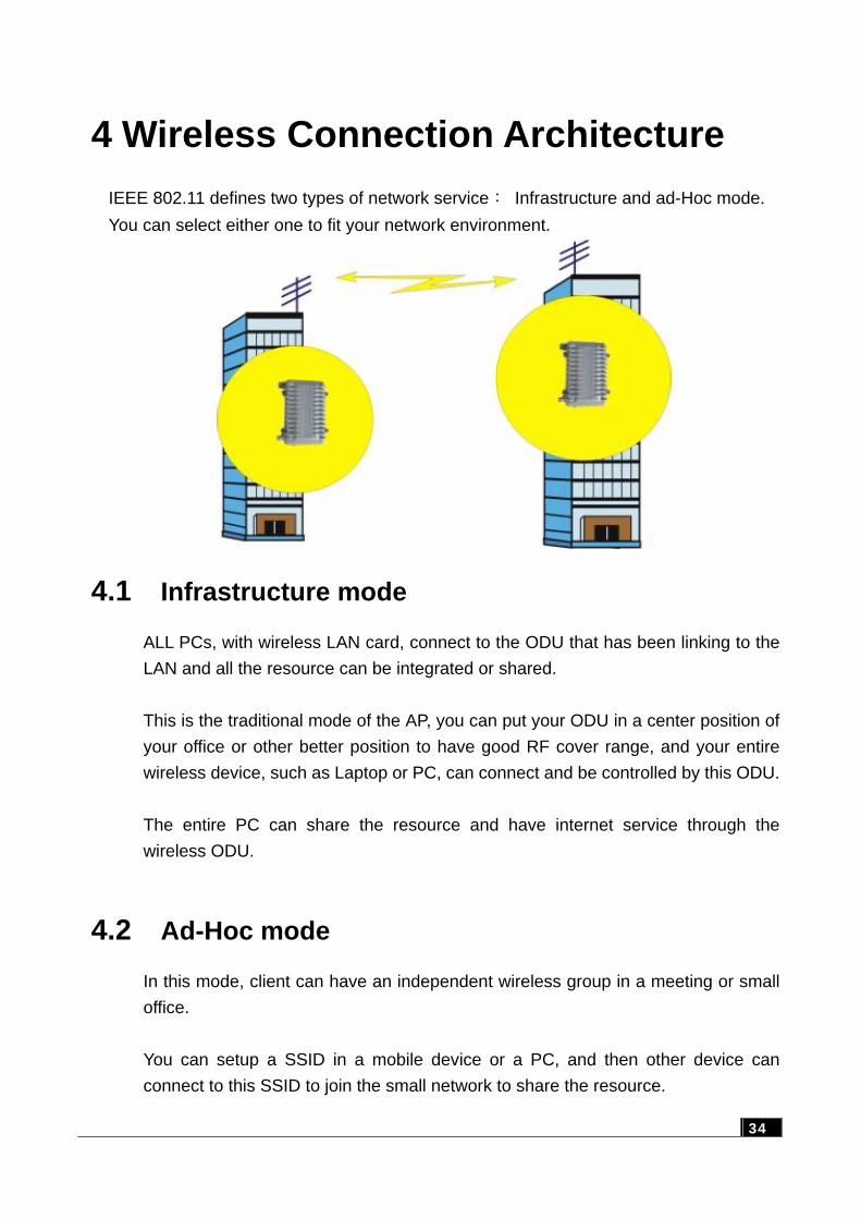
4 Wireless Connection Architecture
IEEE 802.11 defines two types of network service: Infrastructure and ad-Hoc mode. You can select either one to fit your network environment.
4.1 Infrastructure mode
ALL PCs, with wireless LAN card, connect to the ODU that has been linking to the LAN and all the resource can be integrated or shared. This is the traditional mode of the AP, you can put your ODU in a center position of your office or other better position to have good RF cover range, and your entire wireless device, such as Laptop or PC, can connect and be controlled by this ODU. The entire PC can share the resource and have internet service through the wireless ODU.
4.2 Ad-Hoc mode
In this mode, client can have an independent wireless group in a meeting or small office. You can setup a SSID in a mobile device or a PC, and then other device can connect to this SSID to join the small network to share the resource.
34
4.3 Wireless AP Functions
Access Point can have various functions to make your network more effectively.
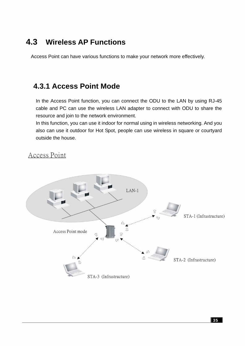
4.3.1 Access Point Mode
In the Access Point function, you can connect the ODU to the LAN by using RJ-45 cable and PC can use the wireless LAN adapter to connect with ODU to share the resource and join to the network environment. In this function, you can use it indoor for normal using in wireless networking. And you also can use it outdoor for Hot Spot, people can use wireless in square or courtyard outside the house.
35
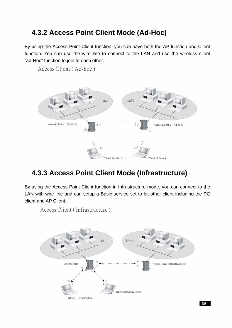
4.3.2 Access Point Client Mode (Ad-Hoc)
By using the Access Point Client function, you can have both the AP function and Client function. You can use the wire line to connect to the LAN and use the wireless client “ad-Hoc” function to join to each other.
4.3.3 Access Point Client Mode (Infrastructure)
By using the Access Point Client function in Infrastructure mode, you can connect to the LAN with wire line and can setup a Basic service set to let other client including the PC client and AP Client.
36
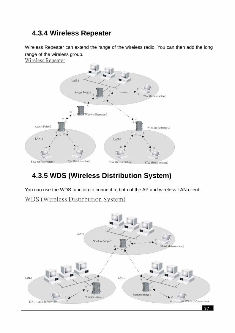
4.3.4 Wireless Repeater
Wireless Repeater can extend the range of the wireless radio. You can then add the long range of the wireless group.
4.3.5 WDS (Wireless Distribution System)
You can use the WDS function to connect to both of the AP and wireless LAN client.
37
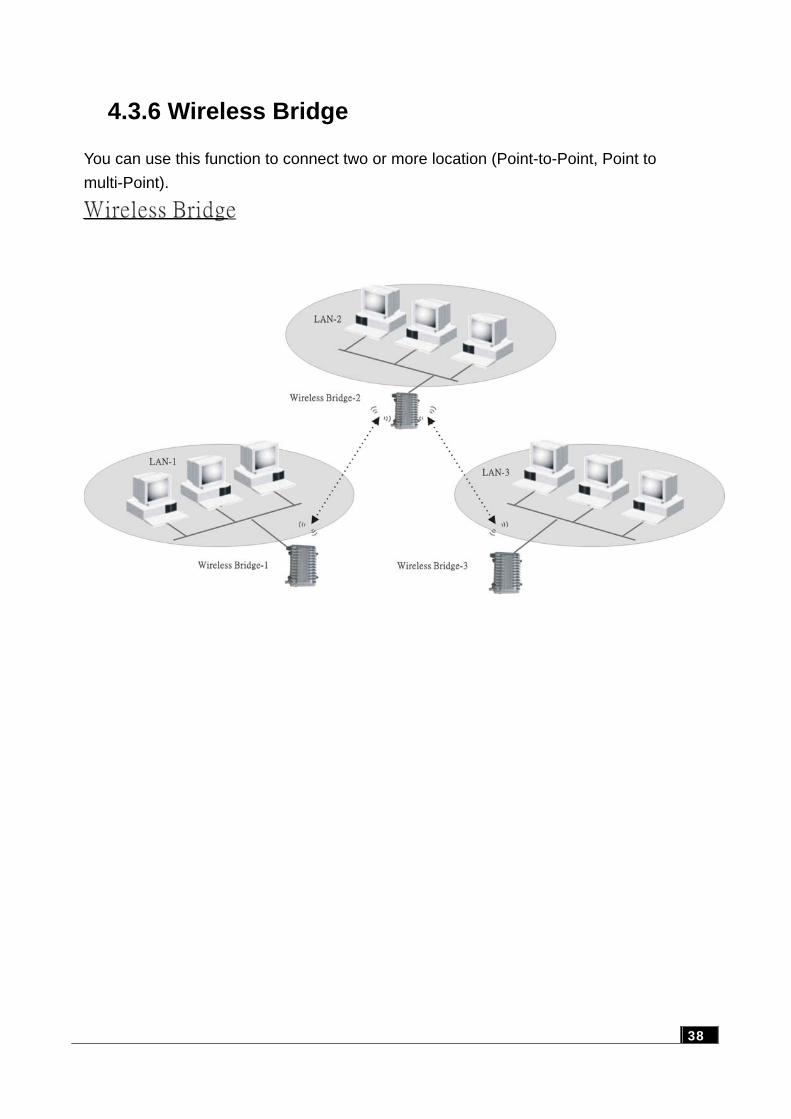
4.3.6 Wireless Bridge
You can use this function to connect two or more location (Point-to-Point, Point to multi-Point).
38
39
4.4 Selecting an appropriate site 1 Selecting an appropriate site for your ODU will ensure the best performance. 2 Avoid locating the ODU near metal objects such as appliances (e.g., refrigerators,
ovens, and washer/dryers). While considering the location of the ODU, keep in mind that your appliances may be on the other side of the wall.
3 For best performance, locate the ODU as close to the center of the area that you will
be covering. Keep in mind that radio waves radiate outward from the ODU in a circular pattern.
4 Normally, the higher that you locate the ODU, the better the performance and range
will be. 5 Remember that many things can cause a degrade of the radio signal including brick
walls, metal-reinforced concrete, the metal housing of appliances, or even wiring in the walls.
4.5 Power over Ethernet
Power over Ethernet is a new industrial standard for products that are difficult to have the power supply. Only one RJ-45 cable can transmit both data and power.
We recommend the Poe system for easier installation while using less cable lines. Plugging with the Poe device, you can have low cost, easy maintenance, convenience, high reliability, high stability, and high security.