Embed Size (px)
Citation preview
Cisco SeOL-21122-01
C H A P T E R 5
Wireless LAN DesignCisco Unified Wireless Network ArchitectureWLANs in the schools have emerged as one of the most effective means for connecting to a network, given the mobility of students and staff. The Cisco Unified Wireless Network (CUWN) is a unified wired and wireless network solution that addresses the wireless network security, deployment, management, and control aspects of deploying a wireless network. It combines the best elements of wireless and wired networking to deliver secure, scalable wireless networks with a low total cost of ownership.
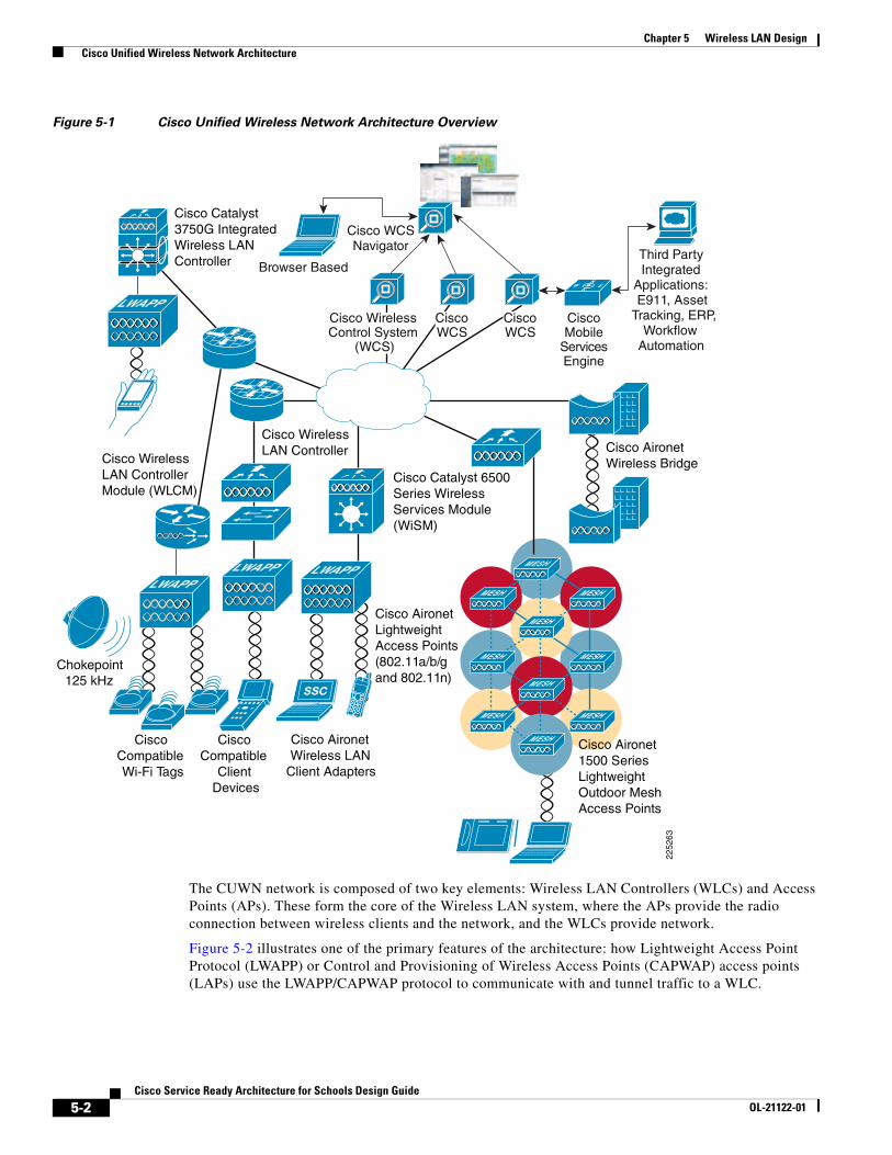
Figure 5-1 shows a high-level topology of the CUWN architecture, which includes Lightweight Access Point Protocol (LWAPP) access points (LAPs), mesh LWAPP APs (MAPs), the Wireless Control System (WCS), and the Wireless LAN Controller (WLC); alternate WLC platforms include the Wireless LAN Controller Module (WLCM) or Wireless Services Module (WiSM). The Cisco Access Control Server (ACS) and its Authentication, Authorization, and Accounting (AAA) features complete the solution by providing RADIUS services in support of wireless user authentication and authorization.
5-1rvice Ready Architecture for Schools Design Guide
Chapter 5 Wireless LAN Design Cisco Unified Wireless Network Architecture
Figure 5-1 Cisco Unified Wireless Network Architecture Overview
The CUWN network is composed of two key elements: Wireless LAN Controllers (WLCs) and Access Points (APs). These form the core of the Wireless LAN system, where the APs provide the radio connection between wireless clients and the network, and the WLCs provide network.
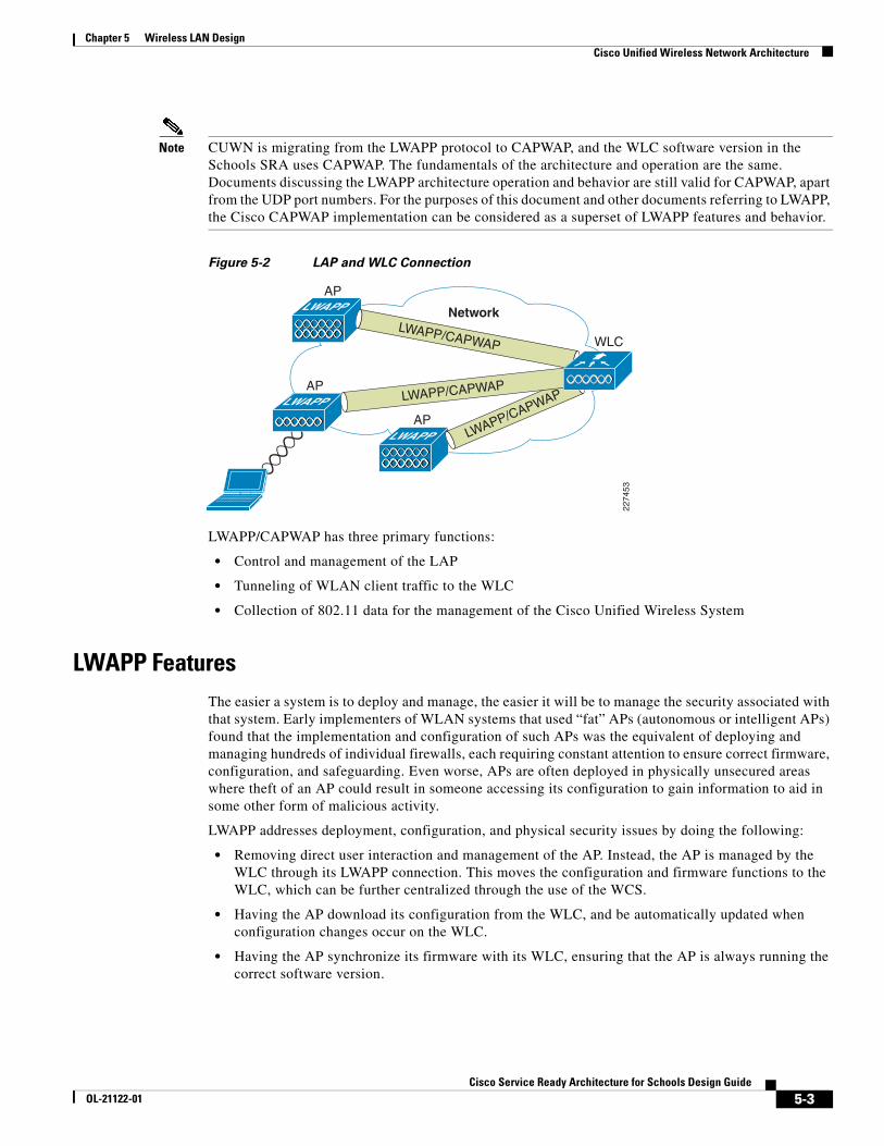
Figure 5-2 illustrates one of the primary features of the architecture: how Lightweight Access Point Protocol (LWAPP) or Control and Provisioning of Wireless Access Points (CAPWAP) access points (LAPs) use the LWAPP/CAPWAP protocol to communicate with and tunnel traffic to a WLC.
Browser Based
CiscoMobile
ServicesEngine
Third PartyIntegrated
Applications:E911, Asset
Tracking, ERP,Workflow
Automation
Cisco WCSNavigator
Cisco AironetLightweight Access Points(802.11a/b/g and 802.11n)
Cisco Compatible Wi-Fi Tags
Chokepoint125 kHz
Cisco Compatible
Client Devices
Cisco Aironet Wireless Bridge
Cisco Wireless LAN Controller
Cisco Wireless LAN Controller Module (WLCM)
Cisco Catalyst3750G IntegratedWireless LANController
Cisco Aironet 1500 Series Lightweight Outdoor Mesh Access Points
Cisco Catalyst 6500 Series Wireless Services Module (WiSM)
Cisco Aironet Wireless LAN
Client Adapters
CiscoWCS
Cisco WirelessControl System
(WCS)
CiscoWCS
W ESN
2252
63
5-2Cisco Service Ready Architecture for Schools Design Guide
OL-21122-01
Chapter 5 Wireless LAN Design Cisco Unified Wireless Network Architecture
Note CUWN is migrating from the LWAPP protocol to CAPWAP, and the WLC software version in the Schools SRA uses CAPWAP. The fundamentals of the architecture and operation are the same. Documents discussing the LWAPP architecture operation and behavior are still valid for CAPWAP, apart from the UDP port numbers. For the purposes of this document and other documents referring to LWAPP, the Cisco CAPWAP implementation can be considered as a superset of LWAPP features and behavior.
Figure 5-2 LAP and WLC Connection
LWAPP/CAPWAP has three primary functions:
• Control and management of the LAP
• Tunneling of WLAN client traffic to the WLC
• Collection of 802.11 data for the management of the Cisco Unified Wireless System
LWAPP FeaturesThe easier a system is to deploy and manage, the easier it will be to manage the security associated with that system. Early implementers of WLAN systems that used “fat” APs (autonomous or intelligent APs) found that the implementation and configuration of such APs was the equivalent of deploying and managing hundreds of individual firewalls, each requiring constant attention to ensure correct firmware, configuration, and safeguarding. Even worse, APs are often deployed in physically unsecured areas where theft of an AP could result in someone accessing its configuration to gain information to aid in some other form of malicious activity.
LWAPP addresses deployment, configuration, and physical security issues by doing the following:
• Removing direct user interaction and management of the AP. Instead, the AP is managed by the WLC through its LWAPP connection. This moves the configuration and firmware functions to the WLC, which can be further centralized through the use of the WCS.
• Having the AP download its configuration from the WLC, and be automatically updated when configuration changes occur on the WLC.
• Having the AP synchronize its firmware with its WLC, ensuring that the AP is always running the correct software version.
LWAPP
LWAPP
LWAPP/CAPWAP
2274
53
LWAPP/CAPWAPLWAPP
Network
WLC
AP
AP
AP
LWAPP/CAPWAP
5-3Cisco Service Ready Architecture for Schools Design Guide
OL-21122-01
Chapter 5 Wireless LAN Design Cisco Unified Wireless Network Architecture
• Storing sensitive configuration data at the WLC, and storing only IP address information on the AP. In this way, if the AP is physically compromised, there is no configuration information resident in NVRAM that can be used to perform further malicious activity.
• Mutually authenticating LAPs to WLCs, and AES encrypting the LWAPP control channel.
In addition to the improvements in physical security, firmware, and configuration management offered by LWAPP, the tunneling of WLAN traffic in an LWAPP-based architecture improves the ease of deployment without compromising the overall security of the solution. LAPs that support multiple WLAN VLANs can be deployed on access-layer switches without requiring dot1q trunking or adding additional client subnets at the access switches. All WLAN client traffic is tunneled to centralized locations (where the WLC resides), making it simpler to implement enterprise-wide WLAN access and security policies.
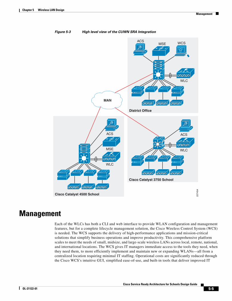
Schools SRA ArchitectureFigure 5-3 shows a simple schematic of the CUWN integration into the schools SRA. The key features of the CUWN integration is the use of a WLC at each school, with the management function (WCS) located at the district office. If context-aware services are implemented, the Cisco Mobility Services Engine (MSE) may be placed at the school; for smaller schools, an MSE at the district office may provide a centralized service.
The standalone WLCs used in this design support AP capacities from 12 to 250 APs per WLC, and multiple WLCs may be deployed at the same school if more than 250 APs are required or if a load sharing or higher availability WLAN solution is required. An alternate higher availability solution is to use a WLC at the district office as a backup WLC for the school’s WLCs. This is known as an N+1 solution, where a district office WLC maintains sufficient capacity to support the APs of any individual school site.
A similar principle to N+1 is used to provide high availability for the AAA service provided by the Cisco ACS server. Each school will have a local ACS server to provide AAA services, and use the district office ACS server as its secondary AAA server.
5-4Cisco Service Ready Architecture for Schools Design Guide
OL-21122-01
Chapter 5 Wireless LAN Design Management
Figure 5-3 High level view of the CUWN SRA Integration
ManagementEach of the WLCs has both a CLI and web interface to provide WLAN configuration and management features, but for a complete lifecycle management solution, the Cisco Wireless Control System (WCS) is needed. The WCS supports the delivery of high-performance applications and mission-critical solutions that simplify business operations and improve productivity. This comprehensive platform scales to meet the needs of small, midsize, and large-scale wireless LANs across local, remote, national, and international locations. The WCS gives IT managers immediate access to the tools they need, when they need them, to more efficiently implement and maintain new or expanding WLANs—all from a centralized location requiring minimal IT staffing. Operational costs are significantly reduced through the Cisco WCS’s intuitive GUI, simplified ease-of-use, and built-in tools that deliver improved IT
Cisco Catalyst 4500 School 2274
54
WLC
MSE
ACSW ES
N
District Office
WLC
MSE WCSACS
W ESN
Cisco Catalyst 3750 School
WLC
ACS
MAN
5-5Cisco Service Ready Architecture for Schools Design Guide
OL-21122-01
Chapter 5 Wireless LAN Design Management
efficiency, lowered IT training costs, and minimized IT staffing requirements, even as the network grows. Cisco WCS lowers operational costs by incorporating the full breadth of management requirements, from radio frequency, to controllers services, and into a single unified platform.
The Cisco WCS scales to manage hundreds of Cisco wireless LAN controllers, which in turn can manage thousands of Cisco Aironet® access points including the next-generation Cisco Aironet 1140 and 1250 Series 802.11n access points. For large-scale indoor and outdoor deployments, Cisco WCS Navigator can be included to simultaneously support up to 20 Cisco WCS platforms and 30,000 Cisco access points. Adding mobility services such as context-aware software and adaptive wireless intrusion prevention systems (wIPS) is simplified through Cisco WCS integration with the Cisco MSE.
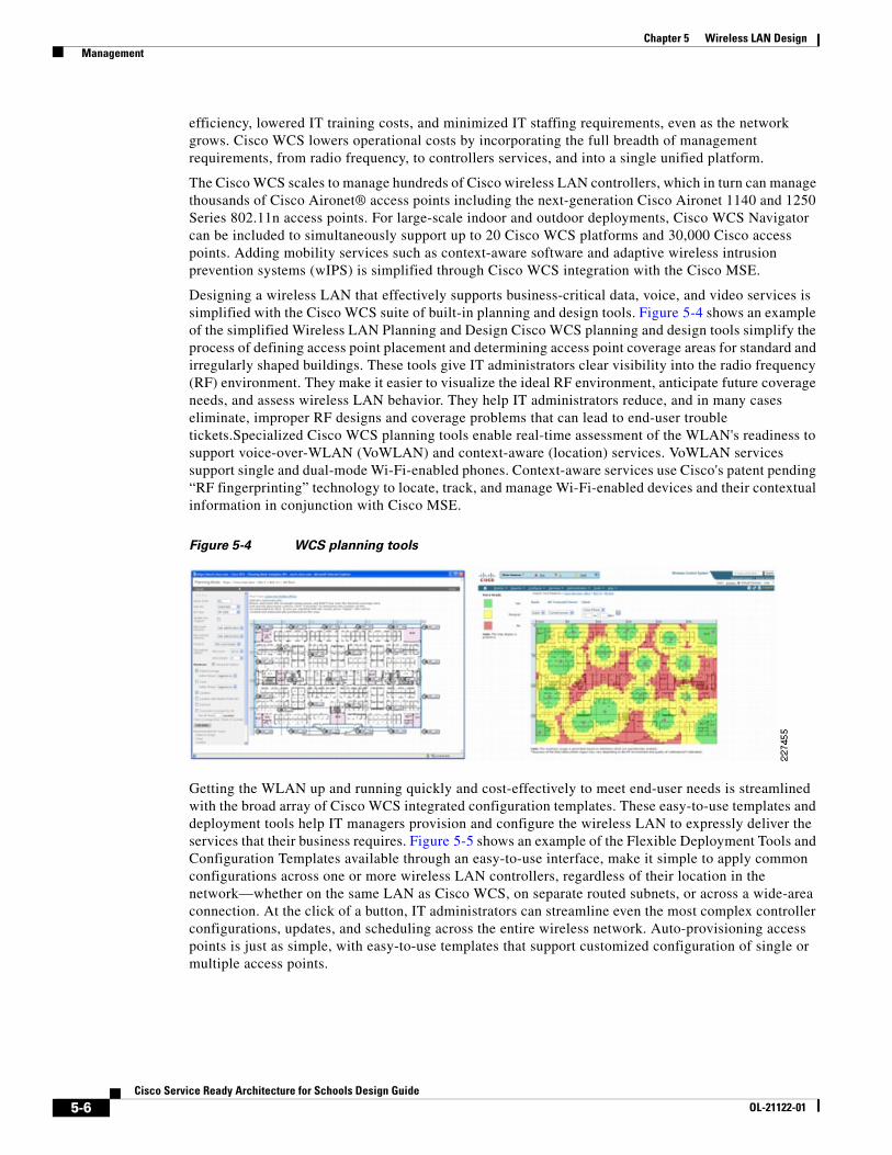
Designing a wireless LAN that effectively supports business-critical data, voice, and video services is simplified with the Cisco WCS suite of built-in planning and design tools. Figure 5-4 shows an example of the simplified Wireless LAN Planning and Design Cisco WCS planning and design tools simplify the process of defining access point placement and determining access point coverage areas for standard and irregularly shaped buildings. These tools give IT administrators clear visibility into the radio frequency (RF) environment. They make it easier to visualize the ideal RF environment, anticipate future coverage needs, and assess wireless LAN behavior. They help IT administrators reduce, and in many cases eliminate, improper RF designs and coverage problems that can lead to end-user trouble tickets.Specialized Cisco WCS planning tools enable real-time assessment of the WLAN's readiness to support voice-over-WLAN (VoWLAN) and context-aware (location) services. VoWLAN services support single and dual-mode Wi-Fi-enabled phones. Context-aware services use Cisco's patent pending “RF fingerprinting” technology to locate, track, and manage Wi-Fi-enabled devices and their contextual information in conjunction with Cisco MSE.
Figure 5-4 WCS planning tools
Getting the WLAN up and running quickly and cost-effectively to meet end-user needs is streamlined with the broad array of Cisco WCS integrated configuration templates. These easy-to-use templates and deployment tools help IT managers provision and configure the wireless LAN to expressly deliver the services that their business requires. Figure 5-5 shows an example of the Flexible Deployment Tools and Configuration Templates available through an easy-to-use interface, make it simple to apply common configurations across one or more wireless LAN controllers, regardless of their location in the network—whether on the same LAN as Cisco WCS, on separate routed subnets, or across a wide-area connection. At the click of a button, IT administrators can streamline even the most complex controller configurations, updates, and scheduling across the entire wireless network. Auto-provisioning access points is just as simple, with easy-to-use templates that support customized configuration of single or multiple access points.
5-6Cisco Service Ready Architecture for Schools Design Guide
OL-21122-01
Chapter 5 Wireless LAN Design Management
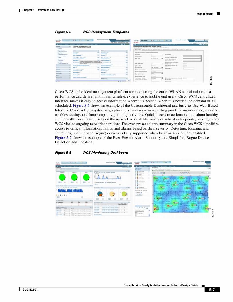
Figure 5-5 WCS Deployment Templates
Cisco WCS is the ideal management platform for monitoring the entire WLAN to maintain robust performance and deliver an optimal wireless experience to mobile end users. Cisco WCS centralized interface makes it easy to access information where it is needed, when it is needed, on demand or as scheduled. Figure 5-6 shows an example of the Customizable Dashboard and Easy-to-Use Web-Based Interface Cisco WCS easy-to-use graphical displays serve as a starting point for maintenance, security, troubleshooting, and future capacity planning activities. Quick access to actionable data about healthy and unhealthy events occurring on the network is available from a variety of entry points, making Cisco WCS vital to ongoing network operations.The ever-present alarm summary in the Cisco WCS simplifies access to critical information, faults, and alarms based on their severity. Detecting, locating, and containing unauthorized (rogue) devices is fully supported when location services are enabled. Figure 5-7 shows an example of the Ever-Present Alarm Summary and Simplified Rogue Device Detection and Location.
Figure 5-6 WCS Monitoring Dashboard
5-7Cisco Service Ready Architecture for Schools Design Guide
OL-21122-01
Chapter 5 Wireless LAN Design Management
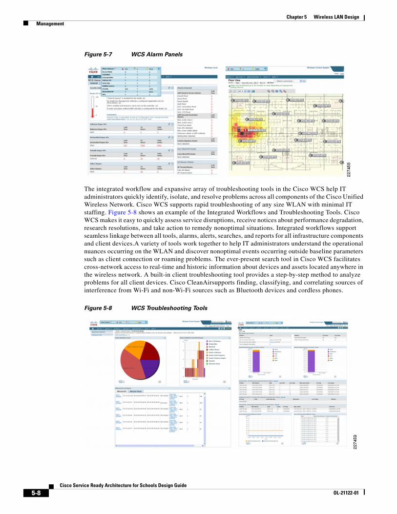
Figure 5-7 WCS Alarm Panels
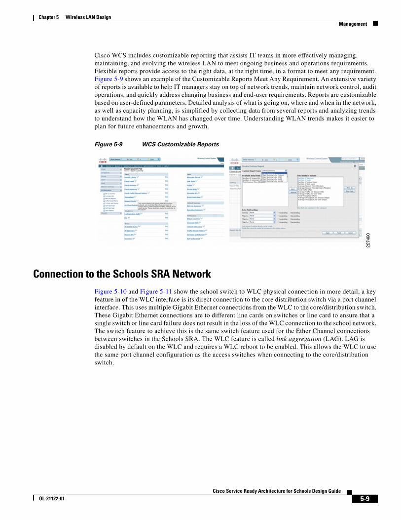
The integrated workflow and expansive array of troubleshooting tools in the Cisco WCS help IT administrators quickly identify, isolate, and resolve problems across all components of the Cisco Unified Wireless Network. Cisco WCS supports rapid troubleshooting of any size WLAN with minimal IT staffing. Figure 5-8 shows an example of the Integrated Workflows and Troubleshooting Tools. Cisco WCS makes it easy to quickly assess service disruptions, receive notices about performance degradation, research resolutions, and take action to remedy nonoptimal situations. Integrated workflows support seamless linkage between all tools, alarms, alerts, searches, and reports for all infrastructure components and client devices.A variety of tools work together to help IT administrators understand the operational nuances occurring on the WLAN and discover nonoptimal events occurring outside baseline parameters such as client connection or roaming problems. The ever-present search tool in Cisco WCS facilitates cross-network access to real-time and historic information about devices and assets located anywhere in the wireless network. A built-in client troubleshooting tool provides a step-by-step method to analyze problems for all client devices. Cisco CleanAirsupports finding, classifying, and correlating sources of interference from Wi-Fi and non-Wi-Fi sources such as Bluetooth devices and cordless phones.
Figure 5-8 WCS Troubleshooting Tools
5-8Cisco Service Ready Architecture for Schools Design Guide
OL-21122-01
Chapter 5 Wireless LAN Design Management
Cisco WCS includes customizable reporting that assists IT teams in more effectively managing, maintaining, and evolving the wireless LAN to meet ongoing business and operations requirements. Flexible reports provide access to the right data, at the right time, in a format to meet any requirement. Figure 5-9 shows an example of the Customizable Reports Meet Any Requirement. An extensive variety of reports is available to help IT managers stay on top of network trends, maintain network control, audit operations, and quickly address changing business and end-user requirements. Reports are customizable based on user-defined parameters. Detailed analysis of what is going on, where and when in the network, as well as capacity planning, is simplified by collecting data from several reports and analyzing trends to understand how the WLAN has changed over time. Understanding WLAN trends makes it easier to plan for future enhancements and growth.
Figure 5-9 WCS Customizable Reports
Connection to the Schools SRA NetworkFigure 5-10 and Figure 5-11 show the school switch to WLC physical connection in more detail, a key feature in of the WLC interface is its direct connection to the core distribution switch via a port channel interface. This uses multiple Gigabit Ethernet connections from the WLC to the core/distribution switch. These Gigabit Ethernet connections are to different line cards on switches or line card to ensure that a single switch or line card failure does not result in the loss of the WLC connection to the school network. The switch feature to achieve this is the same switch feature used for the Ether Channel connections between switches in the Schools SRA. The WLC feature is called link aggregation (LAG). LAG is disabled by default on the WLC and requires a WLC reboot to be enabled. This allows the WLC to use the same port channel configuration as the access switches when connecting to the core/distribution switch.
5-9Cisco Service Ready Architecture for Schools Design Guide
OL-21122-01
Chapter 5 Wireless LAN Design Management
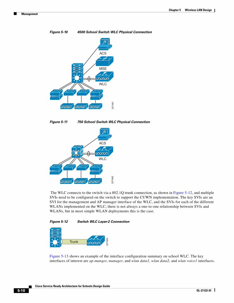
Figure 5-10 4500 School Switch WLC Physical Connection
Figure 5-11 750 School Switch WLC Physical Connection
The WLC connects to the switch via a 802.1Q trunk connection, as shown in Figure 5-12, and multiple SVIs need to be configured on the switch to support the CUWN implementation. The key SVIs are an SVI for the management and AP manager interface of the WLC, and the SVIs for each of the different WLANs implemented on the WLC; there is not always a one-to-one relationship between SVIs and WLANs, but in most simple WLAN deployments this is the case.
Figure 5-12 Switch WLC Layer-2 Connection
Figure 5-13 shows an example of the interface configuration summary on school WLC. The key interfaces of interest are ap-manger, manager, and wlan data1, wlan data2, and wlan voice1 interfaces.
2274
61
WLC
MSE
ACSW ES
N
2274
62
WLC
ACS
2274
63
Trunk
5-10Cisco Service Ready Architecture for Schools Design Guide
OL-21122-01
Chapter 5 Wireless LAN Design Management
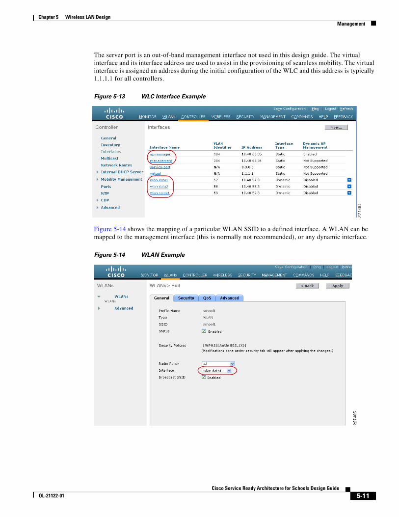
The server port is an out-of-band management interface not used in this design guide. The virtual interface and its interface address are used to assist in the provisioning of seamless mobility. The virtual interface is assigned an address during the initial configuration of the WLC and this address is typically 1.1.1.1 for all controllers.
Figure 5-13 WLC Interface Example
Figure 5-14 shows the mapping of a particular WLAN SSID to a defined interface. A WLAN can be mapped to the management interface (this is normally not recommended), or any dynamic interface.
Figure 5-14 WLAN Example
5-11Cisco Service Ready Architecture for Schools Design Guide
OL-21122-01
Chapter 5 Wireless LAN Design Management
RF Groups and Mobility Groups
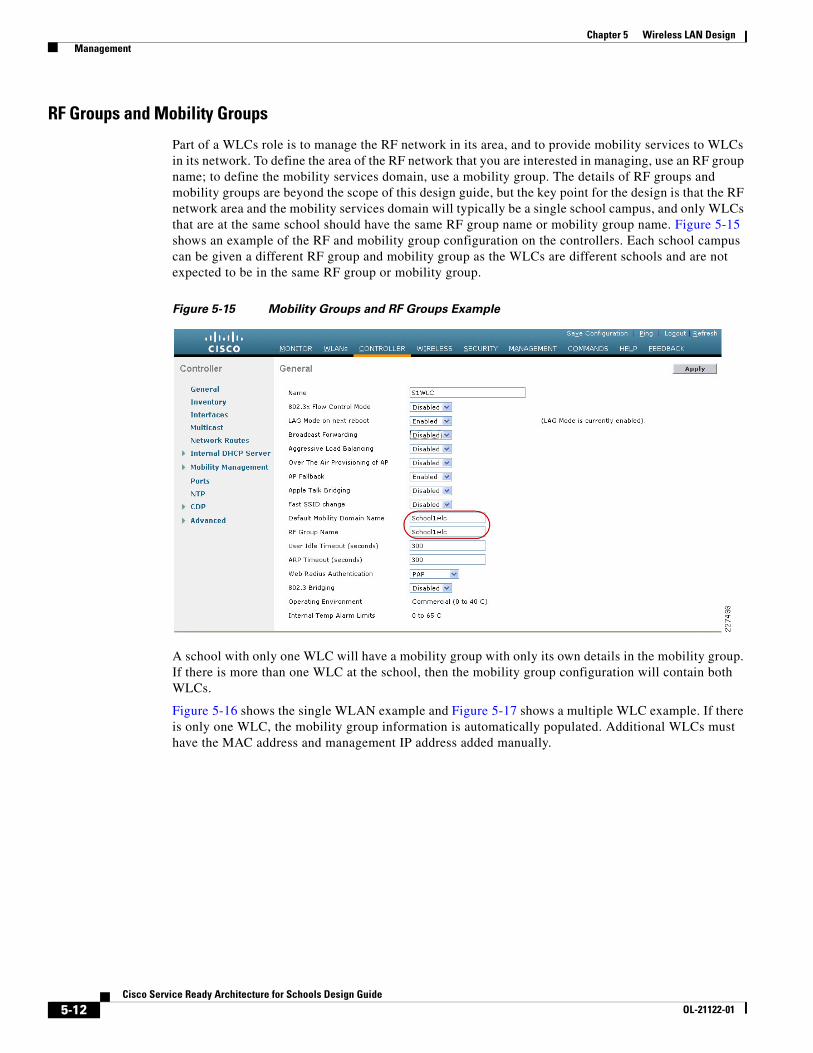
Part of a WLCs role is to manage the RF network in its area, and to provide mobility services to WLCs in its network. To define the area of the RF network that you are interested in managing, use an RF group name; to define the mobility services domain, use a mobility group. The details of RF groups and mobility groups are beyond the scope of this design guide, but the key point for the design is that the RF network area and the mobility services domain will typically be a single school campus, and only WLCs that are at the same school should have the same RF group name or mobility group name. Figure 5-15 shows an example of the RF and mobility group configuration on the controllers. Each school campus can be given a different RF group and mobility group as the WLCs are different schools and are not expected to be in the same RF group or mobility group.
Figure 5-15 Mobility Groups and RF Groups Example
A school with only one WLC will have a mobility group with only its own details in the mobility group. If there is more than one WLC at the school, then the mobility group configuration will contain both WLCs.
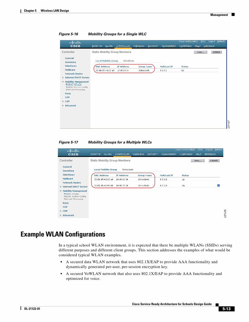
Figure 5-16 shows the single WLAN example and Figure 5-17 shows a multiple WLC example. If there is only one WLC, the mobility group information is automatically populated. Additional WLCs must have the MAC address and management IP address added manually.
5-12Cisco Service Ready Architecture for Schools Design Guide
OL-21122-01
Chapter 5 Wireless LAN Design Management
Figure 5-16 Mobility Groups for a Single WLC
Figure 5-17 Mobility Groups for a Multiple WLCs
Example WLAN ConfigurationsIn a typical school WLAN environment, it is expected that there be multiple WLANs (SSIDs) serving different purposes and different client groups. This section addresses the examples of what would be considered typical WLAN examples.
• A secured data WLAN network that uses 802.1X/EAP to provide AAA functionality and dynamically generated per-user, per-session encryption key.
• A secured VoWLAN network that also uses 802.1X/EAP to provide AAA functionality and optimized for voice.
5-13Cisco Service Ready Architecture for Schools Design Guide
OL-21122-01
Chapter 5 Wireless LAN Design Management
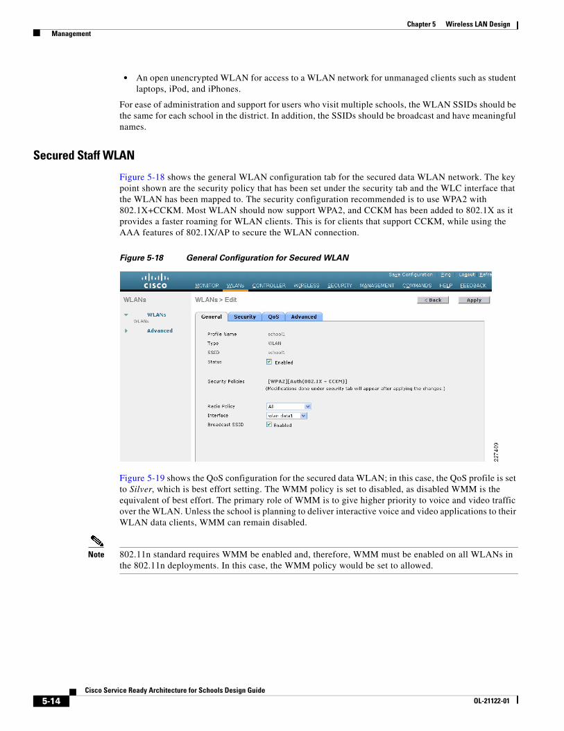
• An open unencrypted WLAN for access to a WLAN network for unmanaged clients such as student laptops, iPod, and iPhones.
For ease of administration and support for users who visit multiple schools, the WLAN SSIDs should be the same for each school in the district. In addition, the SSIDs should be broadcast and have meaningful names.
Secured Staff WLAN
Figure 5-18 shows the general WLAN configuration tab for the secured data WLAN network. The key point shown are the security policy that has been set under the security tab and the WLC interface that the WLAN has been mapped to. The security configuration recommended is to use WPA2 with 802.1X+CCKM. Most WLAN should now support WPA2, and CCKM has been added to 802.1X as it provides a faster roaming for WLAN clients. This is for clients that support CCKM, while using the AAA features of 802.1X/AP to secure the WLAN connection.
Figure 5-18 General Configuration for Secured WLAN
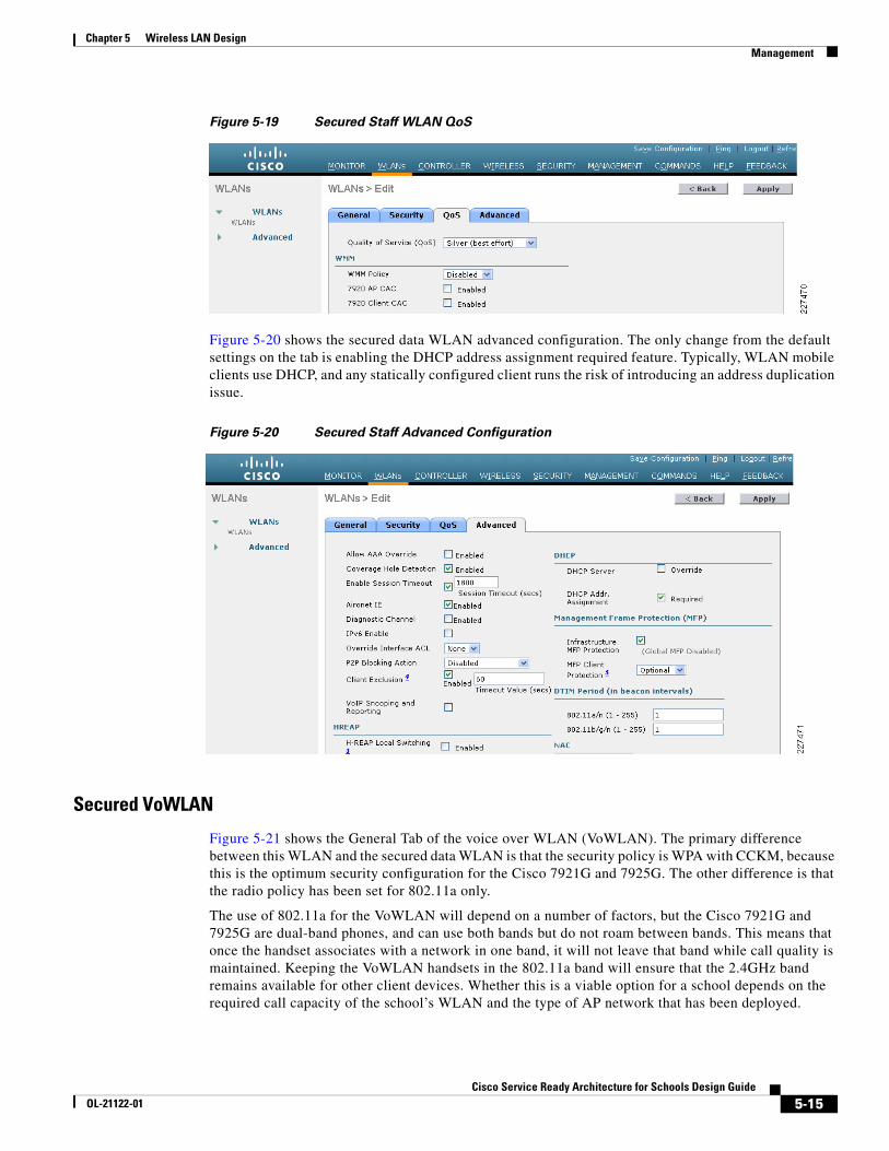
Figure 5-19 shows the QoS configuration for the secured data WLAN; in this case, the QoS profile is set to Silver, which is best effort setting. The WMM policy is set to disabled, as disabled WMM is the equivalent of best effort. The primary role of WMM is to give higher priority to voice and video traffic over the WLAN. Unless the school is planning to deliver interactive voice and video applications to their WLAN data clients, WMM can remain disabled.
Note 802.11n standard requires WMM be enabled and, therefore, WMM must be enabled on all WLANs in the 802.11n deployments. In this case, the WMM policy would be set to allowed.
5-14Cisco Service Ready Architecture for Schools Design Guide
OL-21122-01
Chapter 5 Wireless LAN Design Management
Figure 5-19 Secured Staff WLAN QoS
Figure 5-20 shows the secured data WLAN advanced configuration. The only change from the default settings on the tab is enabling the DHCP address assignment required feature. Typically, WLAN mobile clients use DHCP, and any statically configured client runs the risk of introducing an address duplication issue.
Figure 5-20 Secured Staff Advanced Configuration
Secured VoWLAN
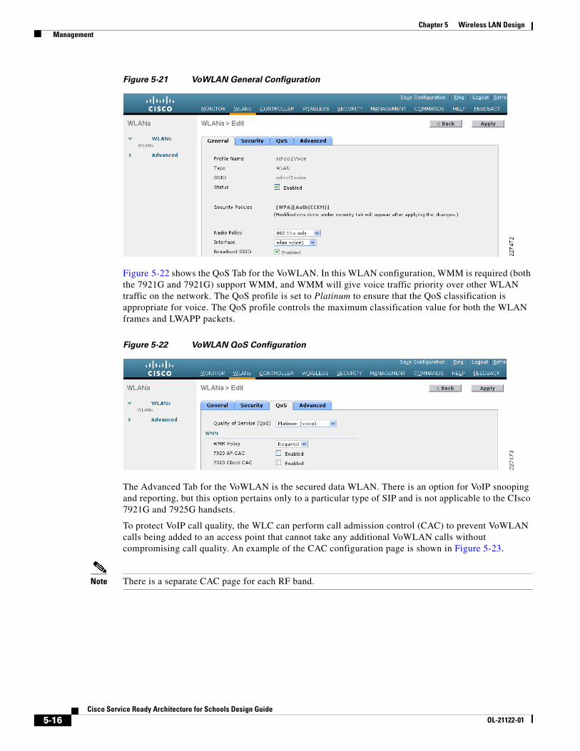
Figure 5-21 shows the General Tab of the voice over WLAN (VoWLAN). The primary difference between this WLAN and the secured data WLAN is that the security policy is WPA with CCKM, because this is the optimum security configuration for the Cisco 7921G and 7925G. The other difference is that the radio policy has been set for 802.11a only.
The use of 802.11a for the VoWLAN will depend on a number of factors, but the Cisco 7921G and 7925G are dual-band phones, and can use both bands but do not roam between bands. This means that once the handset associates with a network in one band, it will not leave that band while call quality is maintained. Keeping the VoWLAN handsets in the 802.11a band will ensure that the 2.4GHz band remains available for other client devices. Whether this is a viable option for a school depends on the required call capacity of the school’s WLAN and the type of AP network that has been deployed.
5-15Cisco Service Ready Architecture for Schools Design Guide
OL-21122-01
Chapter 5 Wireless LAN Design Management
Figure 5-21 VoWLAN General Configuration
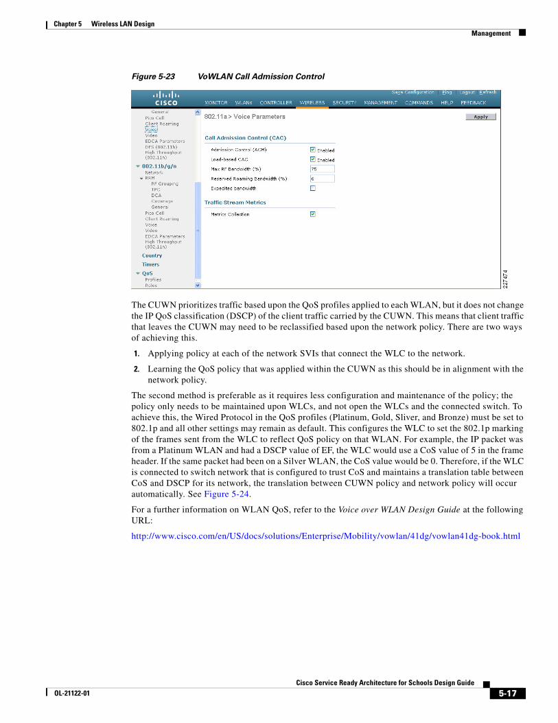
Figure 5-22 shows the QoS Tab for the VoWLAN. In this WLAN configuration, WMM is required (both the 7921G and 7921G) support WMM, and WMM will give voice traffic priority over other WLAN traffic on the network. The QoS profile is set to Platinum to ensure that the QoS classification is appropriate for voice. The QoS profile controls the maximum classification value for both the WLAN frames and LWAPP packets.
Figure 5-22 VoWLAN QoS Configuration
The Advanced Tab for the VoWLAN is the secured data WLAN. There is an option for VoIP snooping and reporting, but this option pertains only to a particular type of SIP and is not applicable to the CIsco 7921G and 7925G handsets.
To protect VoIP call quality, the WLC can perform call admission control (CAC) to prevent VoWLAN calls being added to an access point that cannot take any additional VoWLAN calls without compromising call quality. An example of the CAC configuration page is shown in Figure 5-23.
Note There is a separate CAC page for each RF band.
5-16Cisco Service Ready Architecture for Schools Design Guide
OL-21122-01
Chapter 5 Wireless LAN Design Management
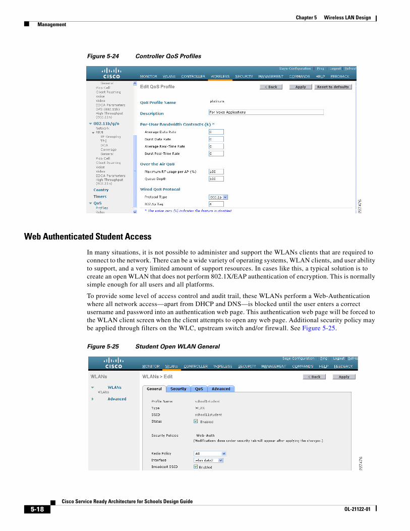
Figure 5-23 VoWLAN Call Admission Control
The CUWN prioritizes traffic based upon the QoS profiles applied to each WLAN, but it does not change the IP QoS classification (DSCP) of the client traffic carried by the CUWN. This means that client traffic that leaves the CUWN may need to be reclassified based upon the network policy. There are two ways of achieving this.
1. Applying policy at each of the network SVIs that connect the WLC to the network.
2. Learning the QoS policy that was applied within the CUWN as this should be in alignment with the network policy.
The second method is preferable as it requires less configuration and maintenance of the policy; the policy only needs to be maintained upon WLCs, and not open the WLCs and the connected switch. To achieve this, the Wired Protocol in the QoS profiles (Platinum, Gold, Sliver, and Bronze) must be set to 802.1p and all other settings may remain as default. This configures the WLC to set the 802.1p marking of the frames sent from the WLC to reflect QoS policy on that WLAN. For example, the IP packet was from a Platinum WLAN and had a DSCP value of EF, the WLC would use a CoS value of 5 in the frame header. If the same packet had been on a Silver WLAN, the CoS value would be 0. Therefore, if the WLC is connected to switch network that is configured to trust CoS and maintains a translation table between CoS and DSCP for its network, the translation between CUWN policy and network policy will occur automatically. See Figure 5-24.
For a further information on WLAN QoS, refer to the Voice over WLAN Design Guide at the following URL:
http://www.cisco.com/en/US/docs/solutions/Enterprise/Mobility/vowlan/41dg/vowlan41dg-book.html
5-17Cisco Service Ready Architecture for Schools Design Guide
OL-21122-01
Chapter 5 Wireless LAN Design Management
Figure 5-24 Controller QoS Profiles
Web Authenticated Student Access
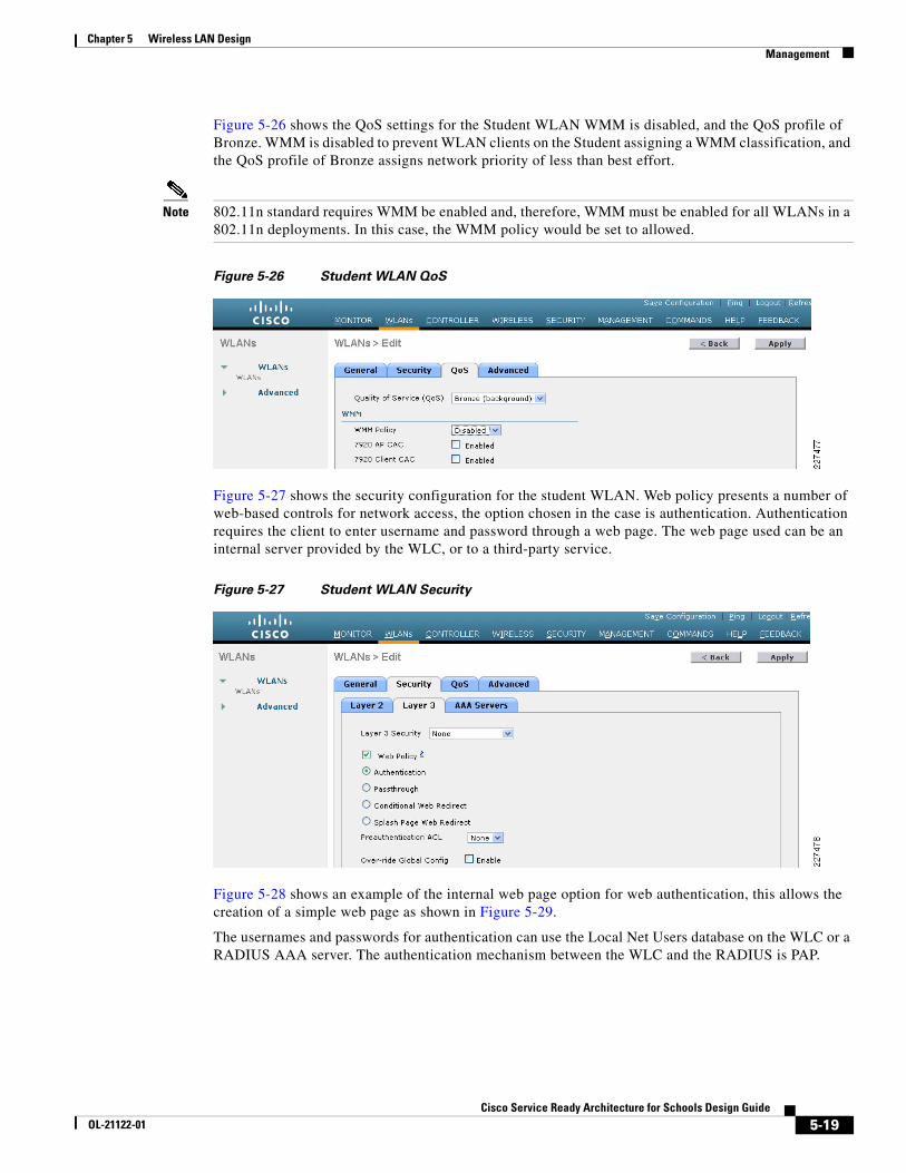
In many situations, it is not possible to administer and support the WLANs clients that are required to connect to the network. There can be a wide variety of operating systems, WLAN clients, and user ability to support, and a very limited amount of support resources. In cases like this, a typical solution is to create an open WLAN that does not perform 802.1X/EAP authentication of encryption. This is normally simple enough for all users and all platforms.
To provide some level of access control and audit trail, these WLANs perform a Web-Authentication where all network access—apart from DHCP and DNS—is blocked until the user enters a correct username and password into an authentication web page. This authentication web page will be forced to the WLAN client screen when the client attempts to open any web page. Additional security policy may be applied through filters on the WLC, upstream switch and/or firewall. See Figure 5-25.
Figure 5-25 Student Open WLAN General
5-18Cisco Service Ready Architecture for Schools Design Guide
OL-21122-01
Chapter 5 Wireless LAN Design Management
Figure 5-26 shows the QoS settings for the Student WLAN WMM is disabled, and the QoS profile of Bronze. WMM is disabled to prevent WLAN clients on the Student assigning a WMM classification, and the QoS profile of Bronze assigns network priority of less than best effort.
Note 802.11n standard requires WMM be enabled and, therefore, WMM must be enabled for all WLANs in a 802.11n deployments. In this case, the WMM policy would be set to allowed.
Figure 5-26 Student WLAN QoS
Figure 5-27 shows the security configuration for the student WLAN. Web policy presents a number of web-based controls for network access, the option chosen in the case is authentication. Authentication requires the client to enter username and password through a web page. The web page used can be an internal server provided by the WLC, or to a third-party service.
Figure 5-27 Student WLAN Security
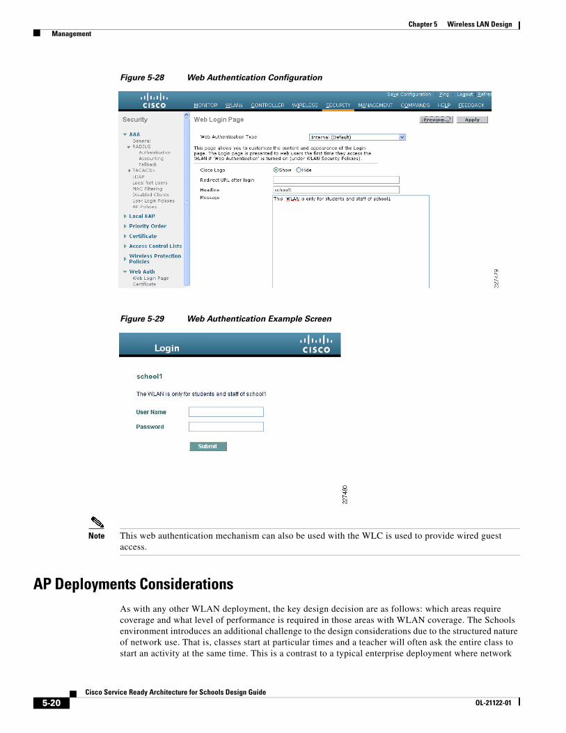
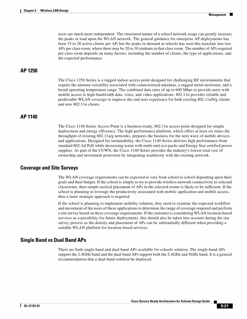
Figure 5-28 shows an example of the internal web page option for web authentication, this allows the creation of a simple web page as shown in Figure 5-29.
The usernames and passwords for authentication can use the Local Net Users database on the WLC or a RADIUS AAA server. The authentication mechanism between the WLC and the RADIUS is PAP.
5-19Cisco Service Ready Architecture for Schools Design Guide
OL-21122-01
Chapter 5 Wireless LAN Design Management
Figure 5-28 Web Authentication Configuration
Figure 5-29 Web Authentication Example Screen
Note This web authentication mechanism can also be used with the WLC is used to provide wired guest access.
AP Deployments ConsiderationsAs with any other WLAN deployment, the key design decision are as follows: which areas require coverage and what level of performance is required in those areas with WLAN coverage. The Schools environment introduces an additional challenge to the design considerations due to the structured nature of network use. That is, classes start at particular times and a teacher will often ask the entire class to start an activity at the same time. This is a contrast to a typical enterprise deployment where network
5-20Cisco Service Ready Architecture for Schools Design Guide
OL-21122-01
Chapter 5 Wireless LAN Design Management
users are much more independent. The structured nature of a school network usage can greatly increase the peaks in load upon the WLAN network. The general guidance for enterprise AP deployments has been 15 to 20 active clients per AP, but the peaks in demand at schools has seen this translate into two APs per class room, where there may be 20 to 30 students in that class room. The number of APs required per class room depends on many factors, including the number of clients, the type of applications, and the expected performance.
AP 1250
The Cisco 1250 Series is a rugged indoor access point designed for challenging RF environments that require the antenna versatility associated with connectorized antennas, a rugged metal enclosure, and a broad operating temperature range. The combined data rates of up to 600 Mbps to provide users with mobile access to high-bandwidth data, voice, and video applications. 802.11n provides reliable and predictable WLAN coverage to improve the end-user experience for both existing 802.11a/b/g clients and new 802.11n clients.
AP 1140
The Cisco 1140 Series Access Point is a business-ready, 802.11n access point designed for simple deployment and energy efficiency. The high-performance platform, which offers at least six times the throughput of existing 802.11a/g networks, prepares the business for the next wave of mobile devices and applications. Designed for sustainability, the Cisco 1140 Series delivers high performance from standard 802.3af PoE while decreasing waste with multi-unit eco-packs and Energy Star certified power supplies. As part of the CUWN, the Cisco 1140 Series provides the industry's lowest total cost of ownership and investment protection by integrating seamlessly with the existing network.
Coverage and Site Surveys
The WLAN coverage requirements can be expected to vary from school to school depending upon their goals and their budget. If the school is simply to try to provide wireless network connectivity in selected classrooms, then simple tactical placement of APs in the selected rooms is likely to be sufficient. If the school is planning to leverage the productivity associated with mobile application and mobile access, then a more strategic approach is required.
If the school is planning to implement mobility solution, they need to examine the expected workflow and movement of the users of these applications to determine the range of coverage required and perform a site survey based on these coverage requirements. If the customer is considering WLAN location-based services as a possibility for future deployments, this should also be taken into account during the site survey process as the density and placement of APs can be substantially different when providing a suitable WLAN platform for location-based services.
Single Band vs Dual Band APs
There are both single-band and dual-band APs available for schools solution. The single-band APs support the 2.4GHz band and the dual-band APs support both the 2.4GHz and 5GHz band. It is a general recommendation that a dual-band solution be deployed.
5-21Cisco Service Ready Architecture for Schools Design Guide
OL-21122-01
Chapter 5 Wireless LAN Design Management
Number of APs Per Room, Coverage in the School
Single band APs vs Dual Band APs
If your goal is to simply provide WLAN coverage without trying to optimize capacity and performance then a single band AP is an appropriate choice, but in most cases a dual band Access Point is a better long term choice.
The longevity of a WLAN deployment is fundamentally determined by it is capacity. A quick look at the dual-band deployment shows that it has twice the capacity of a single-band solution, but a deeper look will reveal that the advantage of a dual-band solution is much greater than an additional radio.
The additional 5GHz radio, of a dual band AP, is able to support a much higher capacity WLAN network as it has access to approximately 7 times the number of non-overlapping channels as the 2.4GHz. In almost all 2.4GHz deployments, APs reusing the three non-overlapping channels interfere with each other and prevent the WLAN deployment from delivering a full WLAN capacity increase when the number of APs is increased. A 5GHz AP is 7 times more likely to be able to delivery additional capacity for the addition of an AP.
Another consideration in the single-band versus dual-band AP discussion is 802.11n performance. 802.11n uses two primary mechanism to provide data rate improvements over the existing 802.11g and 802.11a standards. The first mechanism changes in the modulation, and error correction that can provide a data rate of up to 150Mbps, and the second mechanism is channel binding that combines non-overlapping channels to deliver data rates that are multiples of what a single channel could achieve. Channel binding is only available for the 5GHz band, as there is not sufficient channel capacity to support it in an enterprise 2.4GHz deployment.
Deploying a dual-band WLAN system is not a matter of simply replacing the APs in place, the 5GHz band has different power contraints, and has different propagation properties that need to be considered when deciding on AP density and placement. If fiscally possible, a dual-band AP solution should be planned and deployed initially. This will save an expensive rework layer.
For further discussion on 2.4GHz vs 5GHz capacity, refer to the Voice over WLAN Design Guide at the following URL:
http://www.cisco.com/en/US/docs/solutions/Enterprise/Mobility/vowlan/41dg/vowlan41dg-book.html
Client Considerations
One additional consideration in the single-band versus dual-band AP decision is the client devices that the WLAN network is going to support. Many earlier laptops and mobile devices only supported the 2.4GHz band, and this is still true for many consumer WLAN clients. To take advantage of a dual-band solution a concerted effort needs to be made to ensure that as many clients as possible are also dual-band. For cases where the school is purchasing WLAN clients, they should favor dual-band devices, in recommending WLAN client devices they should point out that the dual-band client devices will have access to a higher performance network. Of course, the first step is having the dual band network in place, for client devices to take advantage of their investment in a higher performance client.
WLC Discovery
CUWN provides auto-discovery functionality for its APs, where an AP upon connection to an appropriately connected network can automatically find and connect to a WLC. The WLC will ensure that the AP is running the appropriate software version, apply the appropriate configuration to that AP, and adjust the radio settings to optimize the AP for its current environment.
Multiple auto-discovery options are available in the CUW:
5-22Cisco Service Ready Architecture for Schools Design Guide
OL-21122-01
Chapter 5 Wireless LAN Design Management
• Over the air: The APs learns the IP address of WLCs from APs in the area which are currently attached to those WLCs
• DHCP: The APs learns the IP address(es) of the WLCs as part of its DHCP address assignment
• DNS: The APs learn the IP address(es) of the WLCs by querying and well known DNS name CISCO-LWAPP-CONTROLLER.<localdomain.com>
• Staging: Have the AP join a WLC prior to them being deployed, and the APs will attempt to rejoin this WLC when reconnected to the network
• Static Configuration: The APs can be manually configured with the WLC IP address prior to being connected to the networks
Given that the schools architecture utilizes a local DNS server for school to ensure survivability the use of the DNS discovery provides the simplest WLC discovery mechanism.
For details about how to configure DHCP discovery, refer to the DHCP OPTION 43 for Lightweight Cisco Aironet Access Points Configuration Example at the following URL:
http://www.cisco.com/en/US/tech/tk722/tk809/technologies_configuration_example09186a00808714fe.shtml
WLC Failover Options
CUWN provides multiple failover options allowing APs to make a choice between WLCs based upon configured priorities. When an AP goes through its discovery process it learns about all of the WLCs in the mobility group, and can prioritize based upon its high availability (HA) configuration or choose an WLC based upon loads.
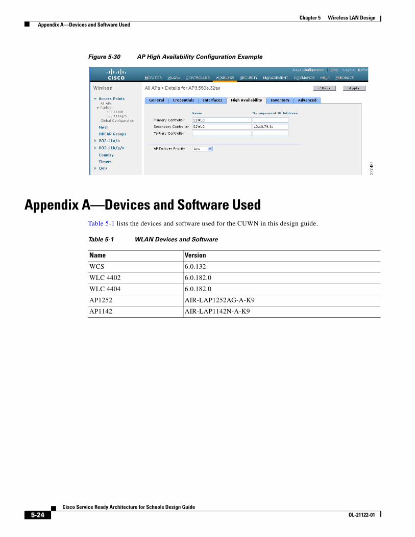
In network architectures, such as the schools SRA, where there is a high-speed WAN/MAN that makes AP failover to a remote WLC—such as the district Office WLC—feasible, APs can be configured to failover to a WLC outside their mobility group. In this scenario, the remote WLC would not be in the Mobility Group that is learned during the AP discovery process, and the IP address of the remote WLC need to be provided in the HA configuration.
This feature allows the distinct office to become a backup WLC for school sites in an event of an WLC outage at the school. For this to be effective, a common WLAN SSID naming policy for key WLANs needs to be implemented within the school district to ensure that WLAN client do not have to be reconfigured in the event of an AP failover to the district office WLC. This type of HA configuration is call N+1 where a single district office WLC is able to provide HA at a much lower cost than a traditional 1+1 design which would require additional WLCs at each school. See Figure 5-30.
5-23Cisco Service Ready Architecture for Schools Design Guide
OL-21122-01
Chapter 5 Wireless LAN Design Appendix A—Devices and Software Used
Figure 5-30 AP High Availability Configuration Example
Appendix A—Devices and Software Used Table 5-1 lists the devices and software used for the CUWN in this design guide.
Table 5-1 WLAN Devices and Software
Name Version
WCS 6.0.132
WLC 4402 6.0.182.0
WLC 4404 6.0.182.0
AP1252 AIR-LAP1252AG-A-K9
AP1142 AIR-LAP1142N-A-K9
5-24Cisco Service Ready Architecture for Schools Design Guide
OL-21122-01