Embed Size (px)
Citation preview
Wireless Identification System to Assist Sight-Constrained People
Design Report
Project ID: Dec06-06
Client: Mr. Curtis Chong
Iowa Department for the Blind
Faculty Advisor: Dr. Zhengdao Wang
Team Members: Jerad Harmsen, EE Nicholas Kayser, EE
Daniel Ketcham, CprE/EE Rajesh Venkatachalam, EE/Fin
DISCLAIMER: This document was developed as a part of the requirements of an electrical and computer engineering course at Iowa State University, Ames, Iowa. This document does not constitute a professional engineering design or a professional land surveying document. Although the information is intended to be accurate, the associated students, faculty, and Iowa State University make no claims, promises, or guarantees about the accuracy, completeness, quality, or adequacy of the information. The user of this document shall ensure that any such use does not violate any laws with regard to professional licensing and certification requirements. This use includes any work resulting from this student-prepared document that is required to be under the responsible charge of a licensed engineer or surveyor. This document is copyrighted by the students who produced this document and the associated faculty advisors. No part may be reproduced without the written permission of the senior design course coordinator.
3 May 2006
Dec06-06 Project Plan CprE/EE 491 Revision 2.0
Table of Contents Table of Contents................................................................................................................. i List of Figures ................................................................................................................... iii List of Tables ..................................................................................................................... iv List of Definitions ...............................................................................................................v
1. Introductory Materials ..........................................................................................1 1.1 Executive Summary ..................................................................................1 1.2 Acknowledgement ....................................................................................2 1.3 Problem Statement ....................................................................................3 1.3.1 General Problem Statement ................................................................3 1.3.2 General Solution Approach.................................................................5 1.4 Operating Environment.............................................................................6 1.5 Intended User(s) and Intended Use(s).......................................................6 1.5.1 Intended User(s)..................................................................................6 1.5.2 Intended Use(s) ...................................................................................6 1.6 Assumptions and Limitations ...................................................................6 1.6.1 Initial Assumptions List......................................................................6 1.6.2 Initial Limitations List ........................................................................7 1.7 Expected End Product and Other Deliverables.........................................7 2. Approach and Project Design Results...................................................................8 2.1 Approach Used..........................................................................................8 2.1.1 Design Objectives ...............................................................................8 2.1.2 Functional Requirements ....................................................................8 2.1.3 Design Constraints ..............................................................................8 2.1.4 Technical Approach Considerations and Results ...............................9 2.1.5 Testing Approach Considerations.....................................................10 2.1.6 Recommendations Regarding Project Continuation / Modification.10 2.2 Detailed Design.......................................................................................11 2.2.1 Overview...........................................................................................11 2.2.2 Barcode Scanner ...............................................................................11 2.2.3 Bluetooth Device ..............................................................................12 2.2.4 FM Transmitter and Receiver ...........................................................12 2.2.5 Speaker and Speaker Volume ...........................................................14 2.2.6 Power Supply ....................................................................................14
3. Resources and Schedules ....................................................................................15 3.1 Resource Requirements ..........................................................................15 3.1.1 Personnel Effort Requirements .........................................................15 3.1.2 Other Resource Requirements ..........................................................17 3.1.3 Financial Requirements ....................................................................18 3.2 Schedules ................................................................................................19 4. Closure Materials ................................................................................................20
________________________________________________________________________ Page i
Dec06-06 Project Plan CprE/EE 491 Revision 2.0
4.1 Project Team Information .......................................................................20 4.1.1 Client Information.............................................................................20 4.1.2 Faculty Advisor Information.............................................................20 4.1.3 Project Team Information .................................................................20 4.2 Closing Summary....................................................................................21 4.3 References...............................................................................................22 4.4 Appendix.................................................................................................23 4.4.1 Task 1: Problem Definition...............................................................23 4.4.1.1 Subtask 1a: Client Communication ...........................................23 4.4.1.2 Subtask 1b: Project Proposal .....................................................23 4.4.1.1 Subtask 1c: Website Creation and Maintenance........................23 4.4.2 Task 2: Technology Considerations and Selection...........................23 4.4.2.1 Subtask 2a: Scanner Technology ...............................................24 4.4.2.2 Subtask 2b: Wireless Technology..............................................24 4.4.2.3 Subtask 2c: SCANACANTM ......................................................24 4.4.3 Task 3: End-Product Design .............................................................24 4.4.3.1 Subtask 3a: Wireless ..................................................................24 4.4.3.2 Subtask 3b: Scanner...................................................................24 4.4.3.3 Subtask 3c: Integration of Scanner and Wireless ......................25 4.4.4 Task 4: End-Product Prototype Implementation...............................25 4.4.4.1 Subtask 4a: Wireless ..................................................................25 4.4.4.2 Subtask 4b: Scanner...................................................................25 4.4.4.3 Subtask 4c: Integration of Scanner and Wireless ......................25 4.4.5 Task 5: End-Product Testing ............................................................25 4.4.6 Task 6: End-Product Documentation................................................26 4.4.7 Task 7: End-Product Demonstration.................................................26 4.4.8 Task 8: Project Reporting .................................................................26
________________________________________________________________________ Page ii
Dec06-06 Project Plan CprE/EE 491 Revision 2.0
List of Figures Figure 1.3.1 Omnidirectional Hand-Held Scanner ..............................................................4 Figure 1.3.2 Wireless Scanner Setup ...................................................................................5 Figure 2.2.2 USB Scanner Setup .......................................................................................12 Figure 2.2.4.1 FM Transmitter Schematic .........................................................................13 Figure 2.2.4.2 FM Receiver with Audio Amplifier ...........................................................14 Figure 4.4.1 Gantt Chart Semester 1-1 ..............................................................................27 Figure 4.4.2 Gantt Chart Semester 1-2 ..............................................................................28 Figure 4.4.3 Gantt Chart Semester 2-1 ..............................................................................29 Figure 4.4.4 Gantt Chart Semester 2-2 ..............................................................................30
________________________________________________________________________ Page iii
Dec06-06 Project Plan CprE/EE 491 Revision 2.0
List of Tables Table 3.1.1.1 Personnel Effort Requirements: Original ....................................................15 Table 3.1.1.2 Personnel Effort Requirements: Revised.....................................................16 Table 3.1.2.1 Other Required Resources: Original............................................................17 Table 3.1.2.2 Other Required Resources: Revised ............................................................17 Table 3.1.3.1 Estimated Project Costs: Original................................................................18 Table 3.1.3.2 Estimated Project Costs: Revised ................................................................19
________________________________________________________________________ Page iv

Dec06-06 Project Plan CprE/EE 491 Revision 2.0
List of Definitions Omnidirectional Hand-Held Scanner: a hand-held scanner that can scan in all directions Bluetooth: a short-range radio technology for Internet and mobile devices, aimed at
simplifying communications among them Radio frequency: a frequency in the range within which radio waves may be transmitted SCANACAN™: software distributed by Ferguson Enterprises that allows a scanner to
scan a barcode and transmit it to a computer which in turn will output a voice describing the product, for sight-constrained people
JAWS®: voice synthesizing software distributed by Freedom Scientific that is utilized by
the SCANACAN™ software Microsoft Speech®: Microsoft’s voice synthesizing software that comes standard on
Windows XP HID: Human Interface Device -- any device to interact directly with humans (mostly
input) like keyboard, mouse, joystick, or graphics tablet FM Transmitter: Frequency Modulation Transmitter – a device that encodes data and
transmits it by varying the frequency of a constant amplitude carrier signal FM Receiver: Frequency Modulation Receiver – a device that receives and decodes data
from the varying frequency of the constant amplitude carrier signal USB: Universal Serial Bus -- an external peripheral interface standard for communication
between a computer and external peripherals over an inexpensive cable using biserial transmission
802.11: applies to wireless LANs and provides 1 or 2 Mbps transmission in the 2.4 GHz
band using either frequencies hopping spread spectrum (FHSS) or direct sequence spread spectrum (DSSS).
ISM Bands: Industrial, Scientific and Medical Radio Bands -- originally reserved
internationally for non-commercial use of RF electromagnetic fields for industrial, scientific and medical purposes, but now a part of the radio spectrum that can be used by anybody without a license in most countries
USD: United States Dollar Maxim: http://www.maxim-ic.com/ -- the website where many of the circuit chips are
purchased or specs were looked at
________________________________________________________________________ Page v

Dec06-06 Project Plan CprE/EE 491 Revision 2.0
max2606: compact, high-performance intermediate-frequency (IF) voltage-controlled oscillators (VCOs) designed specifically for demanding portable wireless communication systems, the FM transmitter chip used
________________________________________________________________________ Page vi

Dec06-06 Design Report CprE/EE 491 Revision 2.0
1. Introductory Material . This section contains the definition and the background to the proposed project. Also included in this section are the assumptions and limitations of the design team put on by the instructor, client, and design team. 1.1 Executive Summary This project plan contains the problem definition. This section clearly defines the purpose and requested solution for the given problem. Following the problem definition is the operating environment which details the assumed conditions the final product must be able function in, error-free. Next is the intended user(s) and use(s) section. Here, a description of whom the intended user(s) is (are) along with the intended use(s) of the final product is (are). Before the end product description, the design team lists its assumptions and limitations. These lists are developed to include both the design team and the client’s assumptions and limitations. Lastly, a list is provided containing the final deliverables upon the projects completion. Also contained in this report is the proposed approach for designing and creating the final product. This approach will be followed to create a product that is capable of integrating with the current SCANACAN™ software. Within the proposed approach lies the functional requirements, constraint and technology considerations, technical approach, testing requirements, security and safety considerations, intellectual property and commercialization considerations, and possible risks, proposed milestones, and project tracking. These parts detail the requirements and considerations the design team encounters. Finally, the team’s proposed resources and schedules are detailed. These tables and charts are followed by the project team’s information. Summarizing the proposed project, sight-constrained persons have access to a system that allows the contents of various food products to be made known through the use of a barcode scanner and a personal computer. The draw back to this system is that the barcode scanner must be plugged directly into the computer. This forces users to bring items from storage in the kitchen to the computer and then back to the kitchen, which is a major inconvenience. This project plan details the steps that will be taken by the design team in the creation of the wireless barcode scanner which will be able to implement the current SCANACAN™ software. The scanner will be able to read a barcode at any orientation and send the information to a personal computer located nearby which will decode the barcode. The computer will then send a synthesized voice signal back to the scanner which in turn will play the voice over an enclosed speaker. The design team will build a packaged product which will include the scanner, a wireless transmission system, and owner’s documentation (both written and electronic) in formats that both blind and not blind persons could use.
________________________________________________________________________ Page 1 of 30

Dec06-06 Design Report CprE/EE 491 Revision 2.0
1.2 Acknowledgements Special thanks to Mr. Curtis Chong and the Iowa Department for the Blind for the information and resources provided to allow for the completion of the project. Thanks to Dr. Zhengdao Wang for all his hard work and guidance for this project. Thanks to Ferguson Enterprises for the use of their SCANACAN™ hardware and software. Thanks to Iowa State University for supplying labs, information, resources and for initializing this project with the Iowa Department for the Blind.
________________________________________________________________________ Page 2 of 30

Dec06-06 Design Report CprE/EE 491 Revision 2.0
1.3 Problem Statement A general overview of the design project along with a proposed approach the design team will undertake to complete the project is contained in this section. 1.3.1 General Problem Statement The purpose of this project is to create a wireless hand-held scanner that is capable of reading barcodes, sending the information to a nearby computer, determining the product from the encoded barcode information, and then receiving a wireless audio signal, containing the name of the product from the computer, and outputting that signal in an audible and understandable form for the user to hear from the scanner. The product is intended to be used by sight-constrained persons, many of whom have SCANACAN™ software already installed on their home computers which is currently compatible with a wired scanner. The scanner will be designed to operate with current and future versions of the SCANACAN™ software as well as other software programs. The current SCANACAN™ software is only available for Microsoft® Windows® operating systems. The scanner must be able to transmit the barcode signal throughout the user’s home to the user’s personal computer for decoding purposes. It must also be able to receive the returning wireless audio signal from the computer. The scanner must be able to send and receive wireless signals throughout a home without line of sight and without data loss through obstacles such as walls. The scanner will need to be an Omnidirectional Hand-Held Scanner, as shown in Figure 1.3.1 on the next page, to allow for scanning barcodes at any orientation allowing sight-constrained people to scan products faster.
________________________________________________________________________ Page 3 of 30

Dec06-06 Design Report CprE/EE 491 Revision 2.0
Figure 1.3.1 Omnidirectional Hand-Held Scanner [4]
________________________________________________________________________ Page 4 of 30

Dec06-06 Design Report CprE/EE 491 Revision 2.0
The scanner must be small enough for users of various hands sizes to be able to comfortably use the product. The scanner must be light enough to allow any user to lift and hold the scanner for a reasonable amount of time without causing discomfort. The scanner must also be able to rest in an upright position to allow users to set the scanner on a flat surface and use both hands to hold a product to be scanned. This technique requires the unit to have an anti-slip surface, both for setting down and for holding. The scanner must also run on a common power source. This source must allow for easy replacement by a sight-constrained person. 1.3.2 General Solution Approach The scanner will be developed by researching previously developed laser barcode scanners, both wired and wireless and using the data as the basis of the new scanner. An emphasis will be placed on the Omnidirectional Hand-Held Scanner to allow for the easiest gathering of barcode information. The current SCANACAN™ software will be used for all testing implications of the new wireless scanner. The audible signal will be developed from Freedom Scientific® JAWS® software. All software will be used on a Windows® operating system. Bluetooth technology will be implemented for sending of the digital barcode information from the scanner to the computer. FM transmission will be used for the returning audio signal from the computer to the scanner. The system will be set up according to Figure 1.3.2.
Scanner Bluetooth Transmitter
Bluetooth Receiver
Computer
FM Transmitter
FM ReceiverAmplifierVolume
Control
Speaker Output
Figure 1.3.2: Wireless Scanner Setup
________________________________________________________________________ Page 5 of 30
Dec06-06 Design Report CprE/EE 491 Revision 2.0
1.4 Operating Environment The scanner will be designed for an in-home environment. The most hazardous condition the scanner must withstand is an occasional accidental dropping from an estimated height of 4 feet. It must also be protected from slight water contact, light dust build up, and temperatures ranging from 10-32 °C.
1.5 Intended User(s) and Intended Use(s) The design team will complete the project with the following assumptions about the intended user(s) and its intended use(s). 1.5.1 Intended User(s) The intended users of the wireless barcode scanner are primarily sight-constrained people. The scanner is being developed with the assumption that the end-user has previously installed the SCANACAN™ software on a Windows® based home computer. The scanner will be designed to allow users of all shapes and sizes to comfortably hold and use for a short duration of time, approximately ten minutes. 1.5.2 Intended Use(s) The scanner is intended to be used to scan the barcodes of common household items to determine their contents. The scanner is designed to be rested upon a flat surface where the laser beams are accessible to allow a barcode to be scanned. The scanner can also be held by a user to scan an item in the user’s other hand, on a shelf, or counter.
1.6 Assumptions and Limitations The following two sections contain the project team’s assumptions and limitations. 1.6.1 Initial Assumptions List This list contains the current assumptions of the design team. Any new assumptions the design team makes will be added to this list. All assumptions are/will be approved by the client.
1. SCANACAN™ software will be previously installed on Windows® based home computer
2. User will be sight-constrained 3. User will have capability or access to a resource allowing them to install new
hardware on a personal computer 4. Scanner will be used in a home environment 5. User has Freedom Scientific® JAWS® software installed on home computer 6. User’s home computer is always on
________________________________________________________________________ Page 6 of 30

Dec06-06 Design Report CprE/EE 491 Revision 2.0
7. User has access to power source, either AC outlet or DC batteries, to power the scanner
8. User will be able to hold scanner 9. The wireless signal will be between 905MHz and 925MHz and will not
interfere with common household devices 1.6.2 Initial Limitations List This list contains the current limitations of the design team. Any new limitations of the design team will be added to this list.
1. End product will cost no more than 600 U.S. dollars 2. Product must not weigh more than 5-6 pounds 3. Wireless technology must be powerful enough to operate in the average home 4. The scanner must operate using either household voltages or batteries
1.7 Expected End Product and Other Deliverables The end product will consist of the following items:
1. Hand-held wireless scanner – capable of reading any barcode and allowing SCANACAN™ software to determine the product.
2. Wireless receiving system – collects barcode information from scanner and transmits the signal to the computer and receives audio signal from computer and relays it to the scanner.
3. User’s manual and setup guide. Both will be made available in Braille and in electronic form.
________________________________________________________________________ Page 7 of 30
Dec06-06 Design Report CprE/EE 491 Revision 2.0
2. Approach and Product Design Results . The approach used details the steps that were taken in designing the product. This approach used should be able to be taken by any group of people, and the results from this project should be reproducible. 2.1 Approach UsedThis section of the design report details out the different items the team has taken into consideration while designing the wireless identification system. This section includes items ranging from functional requirements of the wireless scanner to the risks as well as the tracking of progress. These steps should be able to be reproduced by another team to create the same result. 2.1.1 Design Objectives The objectives of this project are very open to interpretation, and can be summed in a few bullet points:
• A wireless scanner needs to be designed. • The scanner needs to interface with a computer for scanning products with
barcodes, similar to what the SCANACAN™ software and hardware produces. • The scanner needs to speak back what the product is on the scanner itself, or in
some other fashion, easily audible to the user. These three points are very simple, but are so broad that there are several different choices that the team had to make in the design of the scanner, which will be discussed later in this section. 2.1.2 Functional Requirements First, the wireless scanner is required to scan a barcode on an unknown item. The scanner will then wirelessly transmit the barcode to the user’s computer in another room, after which the scanner will receive back from the computer a signal. This signal will contain the description of the can’s contents as needed by the end user. The computer will then speak the contents of the product in a synthesized voice. Upon meeting with Mr. Chong, the client, he made some recommendations and requests. Mr. Chong would like the hand-held wireless scanner to have a speaker on it to output the can’s contents. A couple of alternatives that have been considered are a wireless headset coming from the computer or an addition that would allow the speech to be transmitted to a wireless home audio system. 2.1.3 Design Constraints The wireless scanner needs to be low-cost and wireless. Mr. Chong requested the scanner be simple and small, which in turn will keep the cost down. The current wired model on the market runs approximately $600 to $700, which is out of most people’s
________________________________________________________________________ Page 8 of 30

Dec06-06 Design Report CprE/EE 491 Revision 2.0
price range. The project does have a price constraint of $150 from Iowa State University, but other funds will need to be acquired from other sources, due to some internal components, which are unable to be constructed from tools available, costing more than the entire budget allows. Another major constraint is making the scanner wireless as opposed to the current scanner available with the SCANACAN™ software that is a stationary wired scanner. Another constraint of this project is the weight of the scanner itself. Because the scanner will be used around the home, and moved around occasionally, the device should weigh no more than 6 pounds, as anything heavier would be too unwieldy for common use. 2.1.4 Technical Approach Considerations and Results There are a lot of technologies being used inside this scanner, many of which have been chosen out of a wide variety of choices. The scanner that will be used in this system will be based off of the original barcode scanner provided with the SCANACAN™ software. This barcode scanner, omnidirectional in nature, will be the scanner used in the final product. This scanner was chosen because of the familiar interface the current users will have with this scanner. In addition, this scanner meets all the scanning needs that the team will need for the final product. To make the barcode scanner send back information to the computer, the team has decided that a Bluetooth interface will be implemented. 802.11 signals were also under consideration for the scanner, but because of the small, inexpensive implementation for Bluetooth, and the range at which it works, approximately 30 feet; it became the technology of choice for the scanner. On the receiving end of the barcode scanner, an interface that will make the computer think it has a wired barcode scanner attached needs to be created. After close examination of the barcode scanner currently used with the SCANACAN™ software, it has been concluded that the computer uses the barcode scanner as a simple Human Interface Device (HID), which means that a Bluetooth implementation is simple, as installing a USB Bluetooth interface unit into the computer will achieve the desired result. By adding a USB Bluetooth interface unit, the connection from the scanner to the computer will be stable. To send a signal back to the scanner, telling the user what the product is, a simple FM transmitter will be used to send the information. Designing a digital interface built into the scanner to decode a sound signal would not be efficient for this product, as the sound is already being produced through the sound output on the computer. Because of this sound output, an FM transmitter attached to the computer’s sound output via a Y-connector (to allow the user’s current sound output to function correctly) is the most economical and efficient solution. The FM transmitter will send out a low-power signal
________________________________________________________________________ Page 9 of 30
Dec06-06 Design Report CprE/EE 491 Revision 2.0
(at most 30 yards) that will use ISM bands that are free of use for short-range signals such as this application. To produce the sound output on the scanner itself, a simple speaker will be used to produce the sound. Headphones and a headphone jack were considered as viable alternatives to a speaker, but because of the cost and ease of implementing a simple speaker, it will be used instead. This will result in a slightly larger consumption of power, but the ease of use outweighs this power usage. 2.1.5 Testing Approach Considerations The work for the scanner project will occur in Iowa State laboratories. The hardware available for use is sufficient, including, but not limited to, digital multimeters, hand tools, computers with CAD software, and other programs to assist in design of the scanner. Much of the work will be completed on an individual basis by the team, but the team leader will call meetings to make sure the project is on track and the team members are up-to-date on all issues. The team will meet to compile data and discuss major issues concerning the project. As the project is currently under progress, the lab has been an excellent tool in working on the design of this scanner. Most importantly, the research tools available on the web and the references within the lab proved to be immensely useful. Several simpler alternatives to the original design have been found using these computers. In the near future, more work involving the lab equipment, such as soldering tools and other devices, will be necessary to design the prototype off of this design. With respect to the scanner, there has been little discussion regarding the method that will be used to test the barcode scanner. The testing will be done in stages, making sure that each individual part of the barcode scanner works on its own before the whole device is assembled. Once the device is assembled, it will then be fully tested as a whole, making sure that the whole device meets all the requirements set out by Mr. Chong. Once the initial phase of testing has been completed, the device will then be shown to Mr. Chong in a demonstration meeting, showing all the features that the scanner has to offer. At this time, Mr. Chong will then make any suggestions or clarifications that he may see fit, if any. At this time, there are no plans for field-testing the scanner, as the definition set out for the team only requires functionality of the scanner, which can easily be tested in lab environments. Once the prototype is constructed, it may still prove useful to test this scanner outside of lab settings, which may happen at that date. 2.1.6 Recommendations Regarding Project Continuation / Modification The barcode scanner is proving to be easier and easier to work with, and as such, it is the recommendation of the senior design team that this project be continued to completion. Due to the simple nature of the scanner, this project will be able to maintain its schedule, and keep the cost to reasonable levels relative to the initial cost requirements.
________________________________________________________________________ Page 10 of 30
Dec06-06 Design Report CprE/EE 491 Revision 2.0
One idea for future modifications would be a rechargeable battery. The idea would be to have a base stand on the counter of the kitchen, assuming that is the storage location, plugged into the wall that would recharge the scanner’s battery as well as hold the scanner during times it was not being used. A rechargeable battery will reduce the need to purchase batteries for the scanner and allow the design to meet the exact power needs of the scanner. While the rechargeable battery would make continual costs of operation of the barcode scanner less, the initial upfront cost of the scanner may be increased slightly for a specialized rechargeable battery and charger. Another idea for the future would be setting up the Bluetooth to both send and receive the signal from the computer. This would replace the need of the FM receiver and transmitter, reducing the cost of the scanner. However, this would also require additional work on the barcode scanner, as an additional digital decoder would be necessary to implement the Bluetooth technology. 2.2 Detailed DesignThis section of the report will provide details about the project itself, and more information regard specific products that will be used, and specific parts that will be used. In addition, this section also contains estimated work hours for each person on the team, and estimations regarding the amount of time necessary to complete each portion of the project. 2.2.1 Overview The barcode scanner system has only a few parts that when assembled, making the whole device work as it does. As can be seen from Figure 1.3.2, the barcode can be divided up into just those simple components. The project comes into much larger clarity after taking an in-depth discussion on these components. 2.2.2 Barcode Scanner The omnidirectional barcode scanner that will be used in this design will be based off the original barcode scanner that ships with the SCANACAN™ software. The scanner, which can be seen in detail in Figure 1.3.1, is a standard omnidirectional scanner with a USB interface. Because of the simple interface, it becomes quite easy to install the pin outs directly to a Bluetooth chip. Please refer to Figure 2.2.2 for a view of the pin outs for the USB scanner.
________________________________________________________________________ Page 11 of 30

Dec06-06 Design Report CprE/EE 491 Revision 2.0
Pin Name Cable Color Description1 VCC Red +5 VDC 2 D+ White Data - 3 D- Green Data + 4 GND Black GND
Figure 2.2.2: USB Scanner Setup [7] Using this pin layout, it is quite simple to hook up the barcode scanner to a Bluetooth chip, and directly send the signal to the computer. The power pins will be hooked up to the power source of the barcode scanner, while the D+ pin should be connected to the input of the Bluetooth device. The D- pin should not be necessary to hook up, as this pin should be a data-in pin, which is unnecessary in the design. 2.2.3 Bluetooth Device The Bluetooth that will need to implement for this design is a standard Bluetooth transmitter. As far as transmission speeds go, Bluetooth has a range of different bandwidths, making it possible to send more data to the computer at a faster rate. However, since the scanner has very little data to transmit at any given time, this project will use an asynchronous transfer system, allowing for a 723.2Kbps link. The power requirement for this device, which would need to transmit at a range of up to 30 meters, will be 100mW. The allowed frequency range of Bluetooth in the United States is in the 2400MHz range, which means that some minor adjustment controls will be necessary to ensure that a free bandwidth is achieved. There are three separate Bluetooth packages that can be purchased for use: a transmitter, a receiver, and a transceiver. For the team’s purposes, only the transmitter portion is required. The raw data signal from the USB scanner can be fed directly into the transmitter, where it is then sent to the computer’s Bluetooth receiver, which will be supplied with the final product. Once there, the signal will then be treated as an HID signal, and act just like the original barcode scanner normally would have. Bluetooth is a low-power device so the team will have to devise a small circuit setup of some resistors and other circuitry items to reduce the power to the device. The cost of a Bluetooth chip should run no more than $10 USD. 2.2.4 FM Transmitter and Receiver The FM transmitter and receiver will be based primarily off of integrated circuits purchased from Maxim. For the transmitter, a design from Maxim’s website, using a max2606 integrated circuit, makes a simple and power-efficient way to provide sound
________________________________________________________________________ Page 12 of 30

Dec06-06 Design Report CprE/EE 491 Revision 2.0
output on the scanner itself. Please refer to Figure 2.2.4.1 for a detailed view of this radio component.
Figure 2.2.4.1: FM Transmitter Schematic [5]
As seen from Figure 2.2.4.1, an integrated chip will be necessary, along with a few resistors, capacitors, and some potentiometers, all of which can easily be procured at minimal cost. The chip, however, needs to be purchased from Maxim. Through Maxim’s sampling policies, these transmitters can be obtained for free for purposes of prototyping, and will satisfy the needs for this project. To implement this circuit, the design simply needs to be constructed as shown. The antenna output will be connected to a wire antenna set inside the device. On the device itself, the antenna is connected to Out+, Out- and VCC. This chip is actually a multi-use transmitter chip designed by Maxim for applications other than FM transmission, and the pins reflect thus. The left and right RCA jack inputs are used for audio input from the computer, and potentiometers R1 and R2 are used for tuning the frequency output of the circuit. A FM receiver and audio amplifier will be necessary for signal reception and audible output to the end user. A circuit diagram for the FM receiver and audio amplifier can be seen in Figure 2.2.4.2.
________________________________________________________________________ Page 13 of 30
Dec06-06 Design Report CprE/EE 491 Revision 2.0
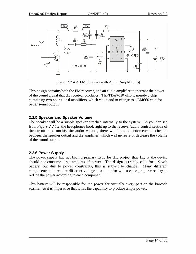
Figure 2.2.4.2: FM Receiver with Audio Amplifier [6]
This design contains both the FM receiver, and an audio amplifier to increase the power of the sound signal that the receiver produces. The TDA7050 chip is merely a chip containing two operational amplifiers, which we intend to change to a LM660 chip for better sound output. 2.2.5 Speaker and Speaker Volume The speaker will be a simple speaker attached internally to the system. As you can see from Figure 2.2.4.2, the headphones hook right up to the receiver/audio control section of the circuit. To modify the audio volume, there will be a potentiometer attached in between the speaker output and the amplifier, which will increase or decrease the volume of the sound output. 2.2.6 Power Supply The power supply has not been a primary issue for this project thus far, as the device should not consume large amounts of power. The design currently calls for a 9-volt battery, but due to power constraints, this is subject to change. Many different components take require different voltages, so the team will use the proper circuitry to reduce the power according to each component. This battery will be responsible for the power for virtually every part on the barcode scanner, so it is imperative that it has the capability to produce ample power.
________________________________________________________________________ Page 14 of 30
Dec06-06 Design Report CprE/EE 491 Revision 2.0
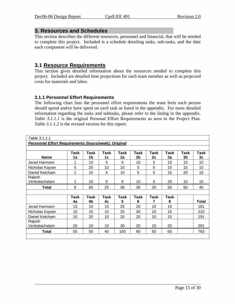
3. Resources and Schedules . This section describes the different resources, personnel and financial, that will be needed to complete this project. Included is a schedule detailing tasks, sub-tasks, and the date each component will be delivered. 3.1 Resource Requirements This section gives detailed information about the resources needed to complete this project. Included are detailed time projections for each team member as well as projected costs for materials and labor. 3.1.1 Personnel Effort Requirements The following chart lists the personnel effort requirements the team feels each person should spend and/or have spent on each task as listed in the appendix. For more detailed information regarding the tasks and subtasks, please refer to the listing in the appendix. Table 3.1.1.1 is the original Personal Effort Requirements as seen in the Project Plan. Table 3.1.1.2 is the revised version for this report.
Table 3.1.1.1 Personnel Effort Requirements (hours/week): Original
Name Task
1a Task
1b Task
1c Task
2a Task
2b Task
2c Task
3a Task
3b Task
3c Jerad Harmsen 1 15 5 5 10 5 10 15 10 Nicholas Kayser 5 20 10 10 5 5 10 15 10 Daniel Ketcham 1 15 5 10 5 5 15 20 10 Rajesh Venkatachalam 1 10 5 5 10 5 20 10 10
Total 8 60 25 30 30 20 55 60 40
Task
4a Task
4b Task
4c Task
5 Task
6 Task
7 Task
8 Total Jerad Harmsen 15 10 10 25 20 10 15 181 Nicholas Kayser 10 15 10 25 30 15 15 210 Daniel Ketcham 10 20 10 20 20 10 15 191 Rajesh Venkatachalam 20 10 10 30 20 15 20 201
Total 55 55 40 100 90 50 65 783
________________________________________________________________________ Page 15 of 30

Dec06-06 Design Report CprE/EE 491 Revision 2.0
Table 3.1.1.2 Personnel Effort Requirements (hours/week): Revised
Name Task
1a Task
1b Task
1c Task
2a Task
2b Task
2c Task
3a Task
3b Task
3c Jerad Harmsen 1 15 1 5 10 5 5 15 15 Nicholas Kayser 5 25 10 10 5 10 5 15 10 Daniel Ketcham 1 15 1 10 5 10 15 25 10 Rajesh Venkatachalam 1 10 1 5 15 5 20 10 10
Total 8 65 13 30 35 30 45 65 45
Task
4a Task
4b Task
4c Task
5 Task
6 Task
7 Task
8 Total Jerad Harmsen 15 10 15 25 20 10 15 182 Nicholas Kayser 10 15 10 25 30 15 15 215 Daniel Ketcham 10 20 10 30 20 10 15 207 Rajesh Venkatachalam 20 10 10 30 15 15 20 197
Total 55 55 45 110 85 50 65 801
________________________________________________________________________ Page 16 of 30
Dec06-06 Design Report CprE/EE 491 Revision 2.0
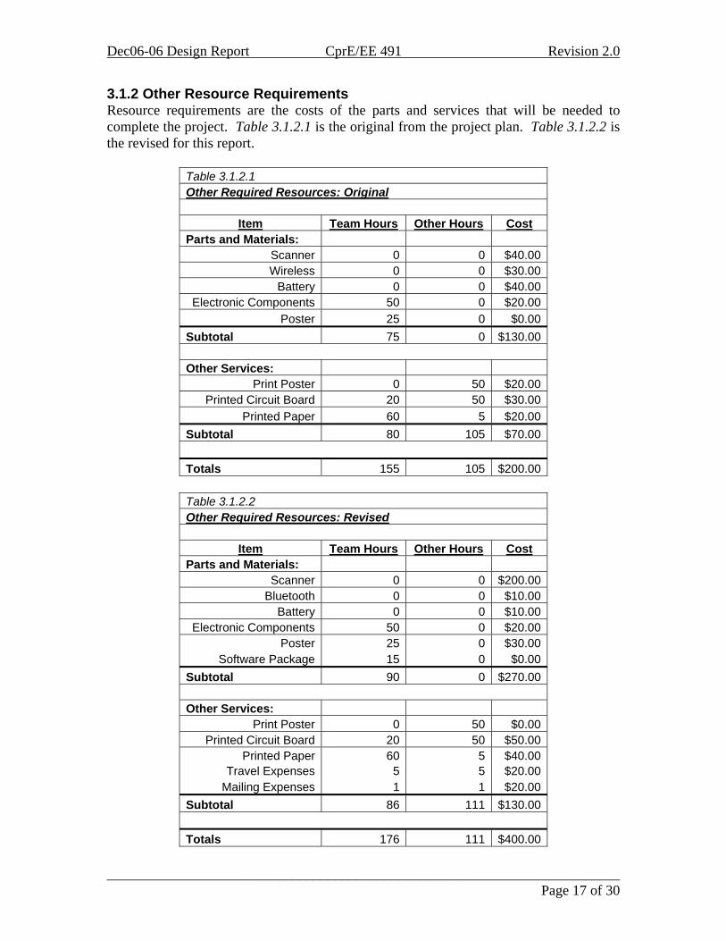
3.1.2 Other Resource Requirements Resource requirements are the costs of the parts and services that will be needed to complete the project. Table 3.1.2.1 is the original from the project plan. Table 3.1.2.2 is the revised for this report.
Table 3.1.2.1 Other Required Resources: Original
Item Team Hours Other Hours Cost Parts and Materials:
Scanner 0 0 $40.00 Wireless 0 0 $30.00
Battery 0 0 $40.00 Electronic Components 50 0 $20.00
Poster 25 0 $0.00 Subtotal 75 0 $130.00
Other Services:
Print Poster 0 50 $20.00 Printed Circuit Board 20 50 $30.00
Printed Paper 60 5 $20.00 Subtotal 80 105 $70.00
Totals 155 105 $200.00
Table 3.1.2.2 Other Required Resources: Revised
Item Team Hours Other Hours Cost Parts and Materials:
Scanner 0 0 $200.00 Bluetooth 0 0 $10.00
Battery 0 0 $10.00 Electronic Components 50 0 $20.00
Poster 25 0 $30.00 Software Package 15 0 $0.00
Subtotal 90 0 $270.00
Other Services: Print Poster 0 50 $0.00
Printed Circuit Board 20 50 $50.00 Printed Paper 60 5 $40.00
Travel Expenses 5 5 $20.00 Mailing Expenses 1 1 $20.00
Subtotal 86 111 $130.00
Totals 176 111 $400.00
________________________________________________________________________ Page 17 of 30
Dec06-06 Design Report CprE/EE 491 Revision 2.0
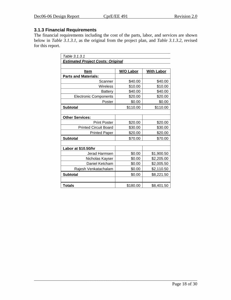
3.1.3 Financial Requirements The financial requirements including the cost of the parts, labor, and services are shown below in Table 3.1.3.1, as the original from the project plan, and Table 3.1.3.2, revised for this report.
Table 3.1.3.1 Estimated Project Costs: Original
Item W/O Labor With Labor Parts and Materials:
Scanner $40.00 $40.00 Wireless $10.00 $10.00
Battery $40.00 $40.00 Electronic Components $20.00 $20.00
Poster $0.00 $0.00 Subtotal $110.00 $110.00
Other Services:
Print Poster $20.00 $20.00 Printed Circuit Board $30.00 $30.00
Printed Paper $20.00 $20.00 Subtotal $70.00 $70.00
Labor at $10.50/hr
Jerad Harmsen $0.00 $1,900.50 Nicholas Kayser $0.00 $2,205.00 Daniel Ketcham $0.00 $2,005.50
Rajesh Venkatachalam $0.00 $2,110.50 Subtotal $0.00 $8,221.50
Totals $180.00 $8,401.50
________________________________________________________________________ Page 18 of 30

Dec06-06 Design Report CprE/EE 491 Revision 2.0
Table 3.1.3.2 Estimated Project Costs: Revised
Item W/O Labor With Labor Parts and Materials:
Scanner $200.00 $200.00 Bluetooth $10.00 $10.00
Battery $10.00 $10.00 Electronic Components $20.00 $20.00
Software/Hardware Package $650.00 $650.00 Poster $30.00 $30.00
Subtotal $920.00 $920.00
Other Services: Print Poster $0.00 $0.00
Printed Circuit Board $50.00 $50.00 Printed Paper $40.00 $40.00
Travel Expenses $20.00 $20.00 Mailing Expenses $20.00 $20.00
Subtotal $130.00 $130.00
Labor at $10.50/hr Jerad Harmsen $0.00 $1,911.00
Nicholas Kayser $0.00 $2,257.50 Daniel Ketcham $0.00 $2,173.50
Rajesh Venkatachalam $0.00 $2,068.50 Subtotal $0.00 $8,410.50
Totals $1,050.00 $9,460.50
3.2 Schedules The Gantt Charts in Figure 4.4.1, Figure 4.4.2, Figure, 4.4.3, Figure 4.4.4 in the appendix indicate the team’s schedule for the year. The blue indicates the original plan while the green indicates the current schedule.
________________________________________________________________________ Page 19 of 30

Dec06-06 Design Report CprE/EE 491 Revision 2.0
4. Closure Materials . This section includes contact information for the client, faculty advisor, and project team. It also summarizes the project and contains all references and appendices. 4.1 Project Team Information This section includes the contact information for client, faculty advisor, and team members for this project. 4.1.1 Client Information Name: Mr. Curtis Chong Title: Program Administrator Address: Field Operations and Access Technology
Iowa Department for the Blind 524 Fourth Street Des Moines, IA 50309
Office Phone: (515) 281-1361 Office Fax: (515) 242-5781 Email: [email protected] 4.1.2 Faculty Advisor Information Name: Dr. Zhengdao Wang Title: Assistant Professor Address: 3134 Coover Hall Iowa State University Ames, IA 50011 Office Phone: (515) 294-8362 Office Fax: (515) 294-8432 Email: [email protected] 4.1.3 Project Team Information Name: Jerad Harmsen Major: Electrical Engineering Address: 4439 Friley Chamberlain Iowa State University Ames, IA 50012 Phone: (515) 572-5437 Email: [email protected]
________________________________________________________________________ Page 20 of 30
Dec06-06 Design Report CprE/EE 491 Revision 2.0
Name: Nicholas Kayser Major: Electrical Engineering Address: 324 Welch Ave. Apt. # 1 Ames, IA 50014 Phone: (319) 331-2617 Email: [email protected] Name: Daniel Ketcham Major: Computer Engineering / Electrical Engineering Address: 1311 Frederiksen Court Ames, IA 50010 Phone: (515) 572-7764 Email: [email protected] Name: Rajesh Venkatachalam Major: Electrical Engineering Address: 246 North Hyland Ave. Apt. # 204 Ames, IA 50014 Phone: (515) 292-8729 Email: [email protected] 4.2 Closing Summary Identifying food products once they have been purchased and brought home is a difficult task for a sight-constrained person. Currently available to a sight-constrained people is a wired scanning system, but this poses the problems of having to go to the computer when an item needs to be identified, this proves to be an inconvenience and a constraint on time for food preparation. The solution would be a wireless version of the scanner. The approach to the wireless solution will involve a similar scanner compared to the existing scanner; Bluetooth, an FM transmitter and receiver, audio components, and a power source. The wireless scanner will simply take the place of the wired component and integrate into the existing SCANACANTM system. The user will then be able to take the scanner to the item and use the scanner as it is needed around the home.
________________________________________________________________________ Page 21 of 30

Dec06-06 Design Report CprE/EE 491 Revision 2.0
4.3 References
1. Bichan, Mike et al. “The Bluetooth Standard”. <http://www.mit.edu/~ddaly/projects/bluetooth/additional.html>. (25 March 2005).
2. “Iowa State University Phone book.” Iowa State University.
<http://ph.iastate.edu/cgi-bin/phonebook> (26 March 2006).
3. Freedom Scientific. 2006. <http://www.freedomscientific.com/> (26 March 2006).
4. Ferguson Enterprises. 2005. <http://www.fergusonenterprises.com/> (26 March
2006).
5. Maxim-ic. “Single-Chip FM Transmitter Extends Home-Entertainment Systems.” <http://www.maxim-ic.com/appnotes.cfm/appnote_number/1869> (24 March 2006).
6. Mikroelektronika.co.yu. “FM Receiver with Audio Amplifier.”
<http://www.mikroelektronika.co.yu/english/product/books/rrbook/chapter3/chapter3i.htm> (27 April 2006).
7. Pinouts.ru. “USB Printout.” <http://pinouts.ru/data/USB_pinout.shtml> (27
March 2006).
________________________________________________________________________ Page 22 of 30

Dec06-06 Design Report CprE/EE 491 Revision 2.0
4.4 Appendix 4.4.1 Task 1: Problem Definition Task Objective: Define the project and what the scanner is intended to do. Task Approach: The definition of the project will be found through team meetings among
the team members as well as meetings with Dr. Wang and Mr. Chong. These meetings, some of which have already begun, will cover the actual requirements for the scanner, as well as other details and information that will help the team make technological decisions as well.
Task Expected Results: A firm definition of the project that is to be completed.
4.4.1.1 Subtask 1a: Client Communication Task Objective: To meet with the client and discuss the project as well as keep in
touch via email or phone for more information. Task Approach: Setup a meeting with the client to discuss the project and
determine what the client wants out of it. Task Expected Results: The team will design and build the product to the
specifications of the client. 4.4.1.2 Subtask 1b: Project Proposal Task Objective: To have the project proposal written as required by the instructor. Task Approach: Divide the proposal into sections and have each member
contribute. Task Expected Results: The project proposal will be written, giving the team path
to follow for the completion of the project. 4.4.1.3 Subtask 1c: Website Creation and Maintenance Task Objective: To create the required website. Task Approach: Have one member create the site and maintain, with the
contributions of the other members. Task Expected Results: The website will be created and maintained throughout
the project.
4.4.2 Task 2: Technology Considerations and Selection Task Objective: To analyze and discuss what technologies will be implemented in the wireless scanner. After this is accomplished, the selection of technologies will be made, and then implemented. Task Approach: The considerations and selections used for our scanner will be made in a
group decision process, with additional support by the team advisor, Dr. Wang. The team will analyze barcode, RFID, and wireless technologies available for creation of this product. Upon demand, other technologies may be considered as well.
Task Expected Results: The base of technologies will be established, and will then be gathered and tested/modified for interoperability.
________________________________________________________________________ Page 23 of 30

Dec06-06 Design Report CprE/EE 491 Revision 2.0
4.4.2.1 Subtask 2a: Scanner Technology Task Objective: To determine the type of scanner to be used. Task Approach: Assign research to the team members and discuss with the team
the findings. Task Expected Results: From the findings and team discussion, determine the
scanner technology to be used. 4.4.2.2 Subtask 2b: Wireless Technology Task Objective: To determine the type of wireless technology to be used. Task Approach: Assign research to the team members and discuss the findings
with the team. Task Expected Results: Determine the wireless technology to be used from the
findings and discussion. 4.4.2.3 Subtask 2c: SCANACANTM
Task Objective: Determine how the software is used. Task Approach: Test the software by installing it and using it to determine how it
works and how the wireless scanner would be used on it. Task Expected Results: Have an understanding of how the software works and
how to integrate the wireless scanner. 4.4.3 Task 3: End-Product Design Task Objective: To design a functional, ready-to-manufacture barcode scanning product for the Iowa Department for the Blind. Task Approach: The product will be designed based off of preliminary designs. Using
tools from the Town Engineering Lab and products purchased through available funds, the team will assemble the scanner. If any design constraints are run into that may appear as a result of designing this device, the Iowa Department for the Blind may be consulted in order to get more specifics as to what they are looking for or for general feedback.
Task Expected Results: A working barcode scanner will be designed on paper.
4.4.3.1 Subtask 3a: Wireless Task Objective: To design the wireless portion of the project. Task Approach: Use the existing knowledge, what was learned from the research,
and software programs to design the wireless portion. Task Expected Results: Have a working design of the wireless portion. 4.4.3.2 Subtask 3b: Scanner Task Objective: To design the scanner for the project. Task Approach: Use the existing technology and the team’s knowledge to design
a system that would work with the scanner chosen. Task Expected Results: Have a design of the scanner setup.
________________________________________________________________________ Page 24 of 30
Dec06-06 Design Report CprE/EE 491 Revision 2.0
4.4.3.3 Subtask 3c: Integration of Scanner and Wireless Task Objective: To integrate the scanner and wireless technologies.
Task Approach: Use the information and designs for the wireless and scanner and integrate these technologies along with the SCANACANTM software.
Task Expected Results: Have a working design for the system. 4.4.4 Task 4: End-Product Prototype Implementation Task Objective: To create a prototype of the barcode scanner based off the end-product design. Task Approach: The scanner will be created first in the senior design laboratory, located
in Town Engineering, Ames, Iowa. This will be done by all members of the senior design team, both by individual work and group work, as necessary. The team may also ask for feedback on the appearance of the prototype from the Iowa Department for the Blind.
Task Expected Results: To have a working barcode scanner that can be used for testing, input and feedback.
4.4.4.1 Subtask 4a: Wireless Task Objective: Build the wireless portion of the project. Task Approach: Use the design created and appropriate technologies and
equipment to construct the wireless portion. Task Expected Results: Have a working wireless product. 4.4.4.2 Subtask 4b: Scanner Task Objective: Build the scanner portion of the project. Task Approach: Using the appropriate technologies and tools as well as the design
to construct the scanner setup. Task Expected Results: Have a working scanner setup. 4.4.4.3 Subtask 4c: Integration of Scanner and Wireless Task Objective: Integrate the scanner and wireless. Task Approach: Construct the final product using the scanner setup and wireless
technology as well as integrating it with the SCANACANTM software. Task Expected Results: Have a working prototype.
4.4.5 Task 5: End-Product Testing Task Objective: To test the prototype of the barcode scanner in a real-life environment. Task Approach: Visually impaired people will test the product for functionality, safety
and usability. The team will give a prototype to the Iowa Department for the Blind to test themselves, to see if it would fit their needs, and make changes if necessary. Also, the team will test to make sure there are no sharp edges or places where one could easily cut oneself, as this scanner will primarily be used by the blind.
________________________________________________________________________ Page 25 of 30

Dec06-06 Design Report CprE/EE 491 Revision 2.0
Task Expected Results: Feedback regarding the functionality of the barcode scanner will be attained, and modifications can be made to the end-product prototype, if necessary.
4.4.6 Task 6: End-Product Documentation Task Objective: To document all processes involving installation and usage and maintenance of the barcode scanner. Task Approach: End product documentation will be done by the entire senior design
group, and will consist of a Microsoft Word document, as computer documentation is the easiest way for visually impaired people to read the document. The team will include diagrams, product details, specifics on how to use the scanner, and instructions, for the sighted people that will help with the setup. This document will be assembled and bound as well for readability and ease of use.
Task Expected Results: A set of documents, also usable for vision-impaired users. These documents should outline the installation, use, and maintenance of the barcode scanner.
4.4.7 Task 7: End-Product Demonstration Task Objective: To demonstrate the functionality of the barcode scanner prototype, and show that it is suitable for market use. Task Approach: Not only will this product be demonstrated by Mr. Chong himself, this
will also be demonstrated to an industrial board review panel. In the case of demonstration with Mr. Chong, the final prototype (all modifications made) will be given to Mr. Chong to get a feel for the product, as well and walk through how to actually use it. To the industrial review panel, the product will be shown, as well as the features that the team implemented will be shown visually.
Task Expected Results: The barcode scanner will be demonstrated to an industrial review panel and to Mr. Curtis Chong, the project’s client. This demonstration will show how to use the product, and demonstrate its features.
4.4.8 Task 8: Project Reporting Task Objective: To give a detailed report including, but not limited to, team members’ hours spent, total resources used, and timetable used. Task Approach: The entire senior design team will make the report. This document will
include detailed instructions and diagrams relating to the construction of the scanner, prices, and costs involved in the creation and testing, and also personal effort required and taken by the team members. This product will also be bound, and given in Microsoft Word document form, for readability and ease of use by blind people.
Task Expected Results: A report will be completed, giving details of the barcode scanner’s design and resources utilized.
________________________________________________________________________ Page 26 of 30

Dec06-06 Design Report CprE/EE 491 Revision 2.0
Figure 4.4.1: Gantt Chart Semester 1-1
________________________________________________________________________ Page 27 of 30

Dec06-06 Design Report CprE/EE 491 Revision 2.0
Figure 4.4.2: Gantt Chart Semester 1-2
________________________________________________________________________ Page 28 of 30

Dec06-06 Design Report CprE/EE 491 Revision 2.0
Figure 4.4.3: Gantt Chart Semester 2-1
________________________________________________________________________ Page 29 of 30

Dec06-06 Design Report CprE/EE 491 Revision 2.0
Figure 4.4.4: Gantt Chart Semester 2-2
________________________________________________________________________ Page 30 of 30