Embed Size (px)
Citation preview
Wireless Engineering and Technology, 2012, 3, 113-124 http://dx.doi.org/10.4236/wet.2012.33018 Published Online July 2012 (http://www.SciRP.org/journal/wet)
113
Wireless Hybrid QoS Architecture with an Enhancement of Fair Intelligent Congestion Control
Li Zheng1, Doan B. Hoang1, Ming Li2
1iNEXT-UTS Centre for Innovation in IT Services and Applications, Faculty of Engineering and Information Technology, University of Technology, Sydney, Australia; 2School of Engineering and Information Technology, Deakin University, Geelong, Australia. Email: [email protected], [email protected], [email protected] Received January 24th, 2012; revised February 22nd, 2012; accepted February 28th, 2012
ABSTRACT
More subtle and explicit QoS control mechanisms are required at the radio access level, even though the simple and scalable Differentiated Services (DiffServ) QoS control model is acceptable for the core of the network. At the radio access level, available resources are severely limited and the degree of traffic aggregation is not significant, thus ren-dering the DiffServ principles less effective. In this paper we present a suitable hybrid QoS architecture framework to address the problem. At the wireless access end, the local QoS mechanism is designed in the context of IEEE 802.11 WLAN with 802.11e QoS extensions; so streams of those session-based applications are admitted, established accord-ing to the traffic profile they require, and guaranteed. As the core in the Admission Control of the hybrid QoS architec-ture, the Fair Intelligent Congestion Control (FICC) algorithm is applied to provide fairness among traffic aggregates and control congestion at the bottleneck interface between the wireless link and the network core via mechanisms of packet scheduling, buffer management, feedback and adjustments. It manages effectively the overloading scenario by preventing traffic violation from uncontrolled traffic, and providing guarantee to the priority traffic in terms of guaran-teed bandwidth allocation and specified delay. Keywords: Hybrid QoS for Wireless Network; Traffic Stream Admission Control; Traffic Specifications;
Fair Intelligent Congestion Control
1. Introduction
QoS limitations/bottleneck today often occurs within the wireless segment from the end-to-end data path based on our deployment experiences of Third Generation (3G) mobile networks and Wireless Local Area Networks (WLANs). This originates from the inherent properties of mobile radio environment [1-3]. While the total re-sources available over the air interface are, on average, sufficient to meet the total resource requirements of the user application sessions admitted to the system, the level of QoS (Quality of Service) desired/expected by users may not be provided. Consequently, services that are tolerant of longer delay and higher rates of data loss is sacrificed. Therefore, more subtle and explicit QoS con-trol mechanisms are required at the radio access level, particularly, with consideration given to the entire (end-to-end) network QoS. The drawbacks of QoS archi-tectures proposed thus far vary from insufficient level of control implemented with DiffServ model only, espe-cially over the resource-limited air interface, to scalabil-ity and complexity problems of solutions involving
end-to-end use of RSVP/IntServ model [3,4]. In this pa-per, a hybrid QoS architecture framework is presented suitable for new generation wireless IP networks. The proposed hybrid architecture follows the principles of Differentiated Service (DiffServ) model over the core part of the network, and the principles of Integrated Ser-vices (IntServ) model locally over the wireless access segment.
As the DiffServ part for the core network has been well studied in the literature, we then only further exam-ine the resource management/explicit Admission Control in the radio access network as the key part of the hybrid QoS architecture for the mobile/wireless environment. The analyses are given in the context of 802.11 WLAN; the admission control over WLAN is largely built on the 802.11 MAC (Medium Access Control) QoS extensions. To address both fair bandwidth sharing among traffic classes and congestion problems encountered in the Ad-mission Control core, an effective rate-based congestion control scheme, the Fair Intelligent Congestion Control FICC [5-7], is adopted and deployed. It intelligently pre- dicts per-queue fair share for all traffic aggregates. FICC
Copyright © 2012 SciRes. WET
Wireless Hybrid QoS Architecture with an Enhancement of Fair Intelligent Congestion Control 114
uses feedback control to keep the Resources Manager operating at a desirable operating point at all times. Re-sources Manager (RM) performs admission control in new flow establishment based on the current usages of the network and nature/class of new flow. It also allows overselling bandwidth when the network is not congested to make efficient use of the network resources. In section IV, a detailed analysis on FICC is given after discussions on the Hybrid Principle and its last-hop explicit Admis-sion Control in Sections 2 and 3.
2. The Hybrid Principle
2.1. Differentiated Services at the Core
QoS architecture at the core network should be able to deliver quantitative differentiated services with suitable network control granularity, scalable and efficient net-work state management. In order to gain architectural scalability, the detailed control information (e.g., per- flow states) and the supporting control mechanisms (e.g., per-flow queuing) are not practical in the design of core networks. Consequently, the resulting level of service differentiation between service classes is often qualita-tive in nature. However, network practitioners have to use quantitative provisioning rules to automatically en-gineer a network that experiences persistent congestion or device failure while attempting to maintain service differentiation. Therefore, a more dynamic form of pro-visioning is needed to compensate for the coarse-grained state information and the lack of network controllability if QoS is to be effectively realized. However, unlike tra-ditional telecommunication networks, where traffic cha- racteristics are well understood and well controlled and long-term capacity planning can be effectively applied, Internet traffic is more diverse and bursty, often exhibit-ing long range dependence [8]. As a result, there is a need to design measurement-based dynamic control al-gorithms that can perform well under diverse traffic con-ditions. Another important challenge facing bandwidth management is the complexity associated with the rate control of traffic aggregates in core networks, which may comprise of flows exiting at different network egress points. This problem occurs when ingress rate control can only be exerted on a per traffic aggregate basis, (i.e., at the root of a traffic aggregate’s point-to-multipoint distribution tree). Under such conditions, any rate reduc-tion of an aggregate would penalize traffic flowing along branches of the tree that are not congested.
Based on the rationale discussed above, we considered differentiated services model for the core network. The model aggregates individual flows into a few classes either on their entrance to the network, or when they cross-administrative domains. At these points only, flows may be rate limited, shaped or marked to conform to
specific traffic profiles. These profiles are either negoti-ated between users and network providers (for aggrega-tion on the entrance to the network) or between neigh- bouring domains (for aggregation between domains). Inside a domain, each router only needs to select a Per Hop Behavior (PHB) for each packet based on its class. State aggregation into a few classes means that this ap-proach scales well, but the guarantees that may be pro-vided are not as fine grained as with the integrated ser-vices, which is not economical and practical to the core network. The architecture intentionally leaves the defini-tion of PHBs and their implementations open to allow different schemes in different domains along the entire data path. The services provided by this architecture are meant to offer various generic QoS levels as opposed to application specific guarantees; hence the decision to map traffic classes instead of flows to PHBs. Only entry points to a network must be aware of both application requirements and PHB semantics to perform flow aggre-gation into classes. However, when resources are limited in some of these domains, traffic policing, meaning rate limiting, shaping and marking would be performed at these points based on traffic profiles. Therefore, depend-ing on the PHBs available, end-to-end services may not be fully offered in a pure DiffServ environment where resources are limited in some of its domains.
2.2. Explicit Control over the Last Hop
As discussed, most traffic profiles are normally static at the entry point of the domains. Both stable allocations for real-time applications like streaming video and best ef-fort allocation for bursty data applications like web transactions are likely if a differentiated services model is used over the wireless last lop. However, due to the increasing diversity of applications, device programma-bility emerging, resources limitation on the wireless links and the natures of wireless channel, a stable allocation service could be easily “overrun” by non real-time sensi-tive data applications. Under such conditions, lower pri-ority packets take advantage of service differentiation by transiting their packets using the higher priority service class. This practice leads to the “tragedy of the com-mons” phenomenon. To avoid a total withdrawal of re-sources from the standard traffic classes with lower QoS requirements, e.g., other than Streaming, there is a share reserved for Interactive traffic from the pool of radio resources in the cell. In times of high load traffic flows with more demanding QoS requirements are allowed to displace flows belonging to applications with lower QoS requirements, but only up to a certain limit. The limits are specified by the maximum allowed number of active sessions for the regarded traffic class. When this limit is reached, the requested QoS is not accepted, but degraded
Copyright © 2012 SciRes. WET
Wireless Hybrid QoS Architecture with an Enhancement of Fair Intelligent Congestion Control 115
to the next-lower-prioritized class. While the limitation on standard traffic classes is in
place, the bandwidth reservation and control mechanisms are still desired for those Interactive traffic, even though they involve a difficult trade-off between guaranteeing the full length of bandwidth reservation and inhibiting excessive bandwidth hogging. Hard reservation guaran-tees bear the complexity of admission control when multi-tiered service quality is required. This requires applications to declare the session length in advance, which none of the widely deployed applications can eas-ily provide. The absence of mobile device participation in the control algorithm makes it hard for bandwidth res-ervation. However, the natures of the applications may imply certain QoS requirements. For example, a VoIP requires a stable bandwidth reservation while a file download may prefer a possible maximum allocation in the short term. The reservation based on these implica-tions may slightly relieve users from declaring session lifetime, and gives early warning of any pending alloca-tion degradation while keeping potential arbitrage.
The resource reservation for a flow is initiated by the receiver of the data flow and resources are requested for simplex flow only. Two-way reservations are emulated by making two simplex flows in opposite directions. The explicit path establishment and resource reservations rely on a signalling mechanism between the receiver and the Admission Controller (AC). However, such signalling is not necessary a RSVP. Even though RSVP is not a rout-ing protocol, it relies on existing and future routing pro-tocols to determine where packets get forwarded. The proper signalling mechanism is only concerned with the QoS of those packets that are forwarded; and should have options for its operation layer (IP-based or MAC-based), The selection should depend on the nature of networks, which may provide simplicity and effectiveness for such signalling. The signalling transports and maintains traffic control and policy control parameters that are opaque to the signalling. Its job is to transport these parameters from node to node, the actual processing of the traffic control and policy control parameters are performed by the relevant traffic control and policy control modules present in a node. These modules should at least include Admission Control and QoS profile negotiation to radio resource status monitoring. Particularly, AC should be responsible for handling activation and deactivation of flow requests, keeping track of traffic load and radio re-source utilisation status, and performing QoS renegotia-tion.
2.3. Overall Hybrid Architecture
While the DiffServ model is useful in providing efficient and scalable QoS control within the network segments characterised by high volume of available resources and
high aggregation of traffic (i.e. core/transport network), it fails to provide subtle enough tools for controlling QoS where the resources are strongly limited and the levels of traffic aggregation are low, e.g. in the wireless access network. The last hop (wireless access) radio resource management cannot rely solely on mechanisms providing differentiated treatment of packets that belong to differ-ent application sessions. To avoid degradation of QoS as the traffic generated by the users within the same access network increases, a mechanism is needed at the access network level to control the total resource requirements of the sessions admitted to the system (explicit admission control), and to reserve the amount of resources required by each session. Such mechanism, operating on a ses-sion-by-session basis, is the characteristic of the IntServ QoS model. The above argument serves as a brief justi-fication for our choice of hybrid model with DiffServ principles applied over the core/transport network do-main, and IntServ principles applied locally to the QoS control over the wireless access segment.
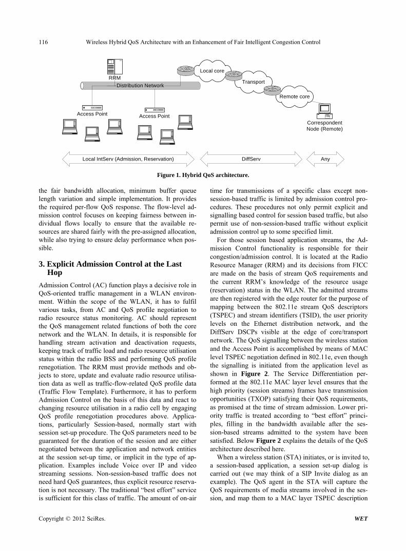
The proposed QoS control architecture in Figure 1 comprises of the DiffServ part in the core/transport net-work segments, and explicit resource management (ad-mission control and reservation) part in the radio access network. Our architecture does not presume any specific QoS control model in the remote network where corre-spondent node (the other party in the application session) is located; it assumes that it is the other network’s re-sponsibility to guarantee, at its end, a QoS level consis-tent with that in the remaining parts of the path. The ex-plicit resource management is localised to a single radio access network domain, where stateful and fine-granu- larity control mechanisms operating at the level of indi-vidual flows and application sessions can be applied without causing scalability and complexity concerns. The resource management at the access network level is based on functional blocks typical of IntServ model, i.e. admission controller and packet (frame) classifier/ scheduler, with multiple queues and service disciplines used to enforce QoS guarantees given to the flows (ses-sions) upon admission. However, unlike the IETF Int-Serv architecture, it does not use explicit end-to-end path establishment and resource reservations such as those available with RSVP. In the Section 3, it is outlined re-liably achieved at the medium access control level as part of MAC functions, in the context of the current 802.11 standards. Central to the admission control, the FICC, an aggregate intelligent congestion control scheme is adopted particularly at the edge devices to ensure that the domain is not congested to the point that it cannot main-tain the agreed level of QoS. FICC plays a key role in Admission Control by suggesting an optimal amount of traffic that should be admitted to maintaining an agree-able QoS level. The main purpose of FICC is to achieve
Copyright © 2012 SciRes. WET
Wireless Hybrid QoS Architecture with an Enhancement of Fair Intelligent Congestion Control
Copyright © 2012 SciRes. WET
116
Distribution Network
Access PointAccess Point
RRMLocal core
Transport
Remote core
CorrespondentNode (Remote)
Local IntServ (Admission, Reservation) DiffServ Any
Figure 1. Hybrid QoS architecture. the fair bandwidth allocation, minimum buffer queue length variation and simple implementation. It provides the required per-flow QoS response. The flow-level ad-mission control focuses on keeping fairness between in-dividual flows locally to ensure that the available re-sources are shared fairly with the pre-assigned allocation, while also trying to ensure delay performance when pos-sible.
3. Explicit Admission Control at the Last Hop
Admission Control (AC) function plays a decisive role in QoS-oriented traffic management in a WLAN environ-ment. Within the scope of the WLAN, it has to fulfil various tasks, from AC and QoS profile negotiation to radio resource status monitoring. AC should represent the QoS management related functions of both the core network and the WLAN. In details, it is responsible for handling stream activation and deactivation requests, keeping track of traffic load and radio resource utilisation status within the radio BSS and performing QoS profile renegotiation. The RRM must provide methods and ob-jects to store, update and evaluate radio resource utilisa-tion data as well as traffic-flow-related QoS profile data (Traffic Flow Template). Furthermore, it has to perform Admission Control on the basis of this data and react to changing resource utilisation in a radio cell by engaging QoS profile renegotiation procedures above. Applica-tions, particularly Session-based, normally start with session set-up procedure. The QoS parameters need to be guaranteed for the duration of the session and are either negotiated between the application and network entities at the session set-up time, or implicit in the type of ap-plication. Examples include Voice over IP and video streaming sessions. Non-session-based traffic does not need hard QoS guarantees, thus explicit resource reserva-tion is not necessary. The traditional “best effort” service is sufficient for this class of traffic. The amount of on-air
time for transmissions of a specific class except non- session-based traffic is limited by admission control pro-cedures. These procedures not only permit explicit and signalling based control for session based traffic, but also permit use of non-session-based traffic without explicit admission control up to some specified limit.
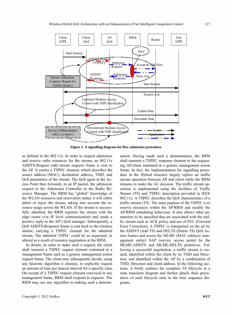
For those session based application streams, the Ad-mission Control functionality is responsible for their congestion/admission control. It is located at the Radio Resource Manager (RRM) and its decisions from FICC are made on the basis of stream QoS requirements and the current RRM’s knowledge of the resource usage (reservation) status in the WLAN. The admitted streams are then registered with the edge router for the purpose of mapping between the 802.11e stream QoS descriptors (TSPEC) and stream identifiers (TSID), the user priority levels on the Ethernet distribution network, and the DiffServ DSCPs visible at the edge of core/transport network. The QoS signalling between the wireless station and the Access Point is accomplished by means of MAC level TSPEC negotiation defined in 802.11e, even though the signalling is initiated from the application level as shown in Figure 2. The Service Differentiation per-formed at the 802.11e MAC layer level ensures that the high priority (session streams) frames have transmission opportunities (TXOP) satisfying their QoS requirements, as promised at the time of stream admission. Lower pri-ority traffic is treated according to “best effort” princi-ples, filling in the bandwidth available after the ses-sion-based streams admitted to the system have been satisfied. Below Figure 2 explains the details of the QoS architecture described here.
When a wireless station (STA) initiates, or is invited to, a session-based application, a session set-up dialog is carried out (we may think of a SIP Invite dialog as an example). The QoS agent in the STA will capture the QoS requirements of media streams involved in the ses-sion, and map them to a MA layer TSPEC description C
Wireless Hybrid QoS Architecture with an Enhancement of Fair Intelligent Congestion Control 117
Start Session
Session Ack
Downlink Data
Start Session
Uplink Data
ADDST Request(TSPEC)
ClientAPPL
Client QoS
ADDST Response
Flow Ack
Admisson Request
RRMAPQoS
EndAPPL
MAC
IPApplication
Service Differentiation (802.11e-MAC)
Stream Admission Control ( Repeat for
Uplink stream)
Router
Accept & Add Flow
Admission Response
Downstream Medium Access Control with TSIP classification
Upstream Medium Access Control with TSIP classification
FICC
Figure 2. A signalling diagram for flow admission procedure. as defined in the 802.11e. In order to request admission and reserve radio resources for the stream, an 802.11e ADDTS-Request (add stream request) frame is sent to the AP. It carries a TSPEC element, which describes the source address (MAC), destination address, TSID, and QoS parameters of the stream. The QoS agent at the Ac-cess Point then forwards, in an IP packet, the admission request to the Admission Controller in the Radio Re-source Manager. The RRM has “global” knowledge of the WLAN resources and reservation status; it will either admit or reject the stream, taking into account the re-source usage across the WLAN. If the stream is success-fully admitted, the RRM registers the stream with the edge router (via IP level communication) and sends a positive reply to the AP’s QoS manager. Subsequently, a QoS ADDTS-Response frame is sent back to the wireless station, carrying a TSPEC element for the admitted stream. The admitted TSPEC could be as requested, or altered as a result of resource negotiation at the RRM.
In details, in order to make such a request, the client shall transmit a TSPEC request element contained in a management frame such as a generic management action request frame. The client may subsequently decide, using any heuristic algorithm it chooses, to explicitly request an amount of time per beacon interval for a specific class. On receipt of a TSPEC request element conveyed in any management frame, RRM shall respond to requests. The RRM may use any algorithm in making such a determi-
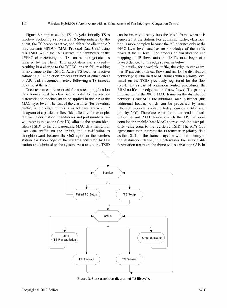
nation. Having made such a determination, the RRM shall transmit a TSPEC response element to the request-ing AP/client contained in a generic management action frame. In fact, the implementation for signalling proce-dure in the Hybrid structure largely replies on traffic stream operation between AP and client while the RRM remains to make the AC decision. The traffic stream op-eration is implemented using the facilities of Traffic Stream (TS) and TSPEC description provided in IEEE 802.11e. A TSPEC describes the QoS characteristics of a traffic stream (TS). The main purpose of the TSPEC is to reserve resources within the AP/RRM and modify the AP/RRM scheduling behaviour. It also allows other pa-rameters to be specified that are associated with the traf-fic stream such as ACK policy and use of FEC (Forward Error Correction). A TSPEC is transported on the air by the ADDTS (Add TS) and DELTS (Delete TS) QoS Ac-tion frames and across the MLME (MAC sublayer man-agement entity) SAP (service access point) by the MLME-ADDTS and MLME-DELTS primitives. Fol-lowing a successful negotiation, a traffic stream is cre-ated, identified within the client by its TSID and Direc-tion, and identified within the AP by a combination of TSID, Direction and client address. In the following sec-tions, it firstly outlines the complete TS lifecycle in a state transition diagram and further details their proce-dures of each lifecycle state in the time sequence dia-grams.
Copyright © 2012 SciRes. WET
Wireless Hybrid QoS Architecture with an Enhancement of Fair Intelligent Congestion Control 118
Figure 3 summarises the TS lifecycle. Initially TS is inactive. Following a successful TS Setup initiated by the client, the TS becomes active, and either the client or AP may transmit MPDUs (MAC Protocol Data Unit) using this TSID. While the TS is active, the parameters of the TSPEC characterising the TS can be re-negotiated as initiated by the client. This negotiation can succeed— resulting in a change to the TSPEC, or can fail, resulting in no change to the TSPEC. Active TS becomes inactive following a TS deletion process initiated at either client or AP. It also becomes inactive following a TS timeout detected at the AP.
Once resources are reserved for a stream, application data frames must be classified in order for the service differentiation mechanism to be applied in the AP at the MAC layer level. The task of the classifier (for downlink traffic, in the edge router) is as follows: given an IP datagram of a particular flow (identified by, for example, the source/destination IP addresses and port numbers; we will refer to this as the flow ID), allocate the stream iden-tifier (TSID) to the corresponding MAC data frame. For user data traffic on the uplink, the classification is straightforward because the QoS agent in the wireless station has knowledge of the streams generated by this station and admitted to the system. As a result, the TSID
can be inserted directly into the MAC frame when it is generated at the station. For downlink traffic, classifica-tion is more complex because the AP operates only at the MAC layer level, and has no knowledge of the traffic flows at the IP level. The process of classification and mapping of IP flows onto the TSIDs must begin at a layer 3 device, i.e. the edge router, as below.
In details, for downlink traffic, the edge router exam-ines IP packets to detect flows and marks the distribution network (e.g. Ethernet) MAC frames with a priority level based on the TSID previously registered for the flow (recall that as part of admission control procedures, the RRM notifies the edge router of new flows). The priority information in the 802.3 MAC frame on the distribution network is carried in the additional 802.1p header (this additional header, which can be processed by most Ethernet products available today, carries a 3-bit user priority field). Therefore, when the router sends a distri-bution network MAC frame towards the AP, the frame contains the mobile host MAC address and the user pri-ority value equal to the registered TSID. The AP’s QoS agent must then interpret the Ethernet user priority field as the TSID for this frame. Together with the identity of the destination station, this determines the service dif-ferentiation treatment the frame will receive at the AP. In
TS Setup
inactive
Failed TS Setup
TS RenegotiationFailed
TS Renegotiation
TS DeletionTS Timeout
active
Figure 3. State transition diagram of TS lifecycle.
Copyright © 2012 SciRes. WET
Wireless Hybrid QoS Architecture with an Enhancement of Fair Intelligent Congestion Control 119
support of classifying downlink traffic using the Ethernet user priority field, the network should be configured as below. The WLAN distribution network should be sepa-rated from other parts of the LAN by an edge router where classification of flows is performed. Fixed hosts attached to the Ethernet (such as servers within the WLAN subnet) must be equipped with a QoS agent that ensures MAC frames sent by them are marked with the appropriate user priority that will be interpreted by the APs as TSID. These seem to be practical to most of re-cent Ethernet subnet today.
4. Fair Intelligence Congestion Control
While the above mechanism is built to provide an effec-tive way to convey traffic information included in the TSPEC, between QoS Agent in the client/applications and RRM/AP, the decisive core part of Admission Con-trol remains in its scheduling and controlling algorithm. Such core decides how to handle stream activation, QoS profile negotiation or/and requests deactivation while keeping track of traffic load and radio resource utilisation status. It certainly provides methods and objects to store, update and evaluate radio resource utilisation data as well as traffic-flow-related QoS profile data (Traffic Flow Template). It has to perform Admission Control on the basis of this data and react to changing resource utilisation in a radio cell by engaging QoS profile rene-gotiation procedures above. Performances on the admis-sion control rely on such decision and its algorithms be-low. Here, we examine the effectiveness and efficiency of FICC, when applying to our hybrid model.
In fact, the keys of FICC are packet scheduling, buffer management, feedback and adjustments. The purpose of such admission control functions is to prevent congestion at the edge as well as within a DiffServ domain and to allocate resources fairly among traffic classes within the domain. It uses available resource information updated to calculate an Explicit Rate (ER) for each class. Per-flow admission control guarantees the fairness among indi-vidual flows within the same class. By doing, the control algorithm firstly attempts to maintain the queue length at the bottlenecked router along the path of the session close to a target point to avoid router buffer overflow and underflow. The bottlenecked router always operates at the full capacity of the output link without interruption from traffic congestion or buffer starvation. Thus, the most efficient throughput can be achieved. In addition, variations on queue length and consequently queuing delays are reduced. On the other hand, FICC attempts to allocate the available bandwidth fairly. Specifically, FICC tries to allocate bandwidth equally among aggre-gates (DSCPs) with equal status and to distribute the un-used bandwidth (left over by constrained aggregates)
fairly among the aggregates that can use an additional share. To achieve this objective, FICC oversells band-width when the network operates below the target point. And each sender is continuously informed about its cur-rent fair share based on the dynamic network traffic con-ditions by the feedback message.
00
00
0
Buffer_Sizefor ,
Buffer_Size
1 *1 for .
Qf Q Q Q
Q
a Q Qf Q Q
Q
Q
(1)
FICC firstly estimates fair share of bandwidth for competing connections and feedback relevant informa-tion concerning the network conditions to the concerned router. Creating feedback loop mechanism between sources and router, a special packet—resource discovery (RD) packet is introduced to collect the router’s state information, which is generated proportionally to the traffic. The source generates forward RD-packets for each flow proportionally to the arrival packet rate, which are turned around by the destination and sent back to the source as backward RD-packets. Such resources infor-mation, e.g. available bandwidth, available buffer is then to calculated in term of capacity for adjustment if re-quired. To achieve such calculation, it is thus essential to relate appropriately the buffer queue length to the degree of network congestion. We use Mean Allowed Class Rate (MACR) to measure the estimated fair share of the aggregate. This MACR in turn is based on the queue length at the router and determines the explicit rate (ER) of an aggregate (the maximum rate at which the network informs the source of the aggregate that it can support). The “queue control function” is expressed using Buffer Utilization Ratio (BUR) of an output queue as the target percentage of buffer capacity that should be occupied. When the target is met, the queue occupancy is Buffer_Size*BUR. This target occupancy is designed to avoid link underutilization and the remaining buffer ca-pacity Buffer_Size*(1 − BUR) is available to absorb packets that might arrive in the queue when the network becomes highly loaded. While BUR defines the target buffer operating point, the corresponding target queue length Q0 (=BUR*Buffer_Size) is often referred to in-stead of BUR. Since the queue builds up and drains out continuously, the congestion function should be con-tinuous to regulate smoothly the queue fluctuations through the computed ER values. A sophisticated and simple queue control function, the piecewise linear con-gestion function f(Q) is shown in (1). It would fine-tune the performance of the congestion control algorithm, however, it should also be pointed out that BUR only indicates the desirable long-term operational level. The actual buffer utilization fluctuates around this level.
Copyright © 2012 SciRes. WET
Wireless Hybrid QoS Architecture with an Enhancement of Fair Intelligent Congestion Control 120
The actual algorithm is described as below. The target is to estimate its available bandwidth and advise the traf-fic sources appropriately. Firstly, the current traffic rate of all aggregates passing through it are estimated and allocated the available bandwidth fairly among its ag-gregates. As below, the MACR contained in TSPEC is updated with an the exponential average factor, which is a true exponential running average of the current load from all aggregates only when the network operates be-low the target operating point. When the network ex-ceeds the target operating point, FICC does not allow MACR to increase further. That means that MACR does not track any ACR value larger than the current MACR when the queue is congested. This rule prevents all those aggregates whose ACRs are already equal larger than the current MACR to increase their rates further, thereby preventing further loading of the network. Instead, all aggregates have to reduce their rates to the same explicit rate and the throttling is performed fairly. However, when the network operates below the target operating point, all aggregates are allowed to increase their rate by a factor greater than 1 (that is what we mean by over-selling), which enables aggregates that are capable of using the available bandwidth to take advantage of it. The explicit rate is calculated as above.
Parameters *β: The average ratio *BUR: Buffer Utilization Ratio *a: Congestion function parameter
Per Queue Variable MACR: Mean Allowed Class Rate DPF: Down Pressure Factor Q0: Target Queue Length
Initialization Q0 = BUR*BufferSize
At router’s network interface if (receive RM (CCR, ER, DIR = forward))
if (QueueLength > Q0) if (ACR < MACR)
MACR = MACR + β*(CCR − MACR) else
MACR = MACR + β*(CCR − MACR) if (receive RM (CCR, ER, DIR = backward))
if (QueueLength > Q0)
0
Buffer_Size Queue LengthDPF
Buffer _Size Q
else
0
0
1 * Queue LengthDPF 1
a Q
Q
ER = max (MCR, min (ER, DPF*MACR) RD protocol is responsible of ensuring communica-
tions FICC in RRM and QoS Agent in clients. Its agent
in AP monitors available resources of wireless links (in MAC level) and provide such feedback to FICC. Such feedback includes MACR and ER. With the supports of the signalling mechanism we discussed in Section 3, RD information captures the resources availability and is conveyed in a TSPEC frame among RRM/AP and client using the mechanism we proposed. In RRM, information is generated, calculated and updated, then is sent to AP for execution of the determination to support clients’ demand. With supports of RD and signalling mechanism discussed above, FICC manage the resources among traffic flows based on the algorithms and mechanism above. By combining such policy core and signalling mechanism in Section 3, all active traffic flows can be served according to the QoS profiles negotiated. Prefera-bly, there are only a limited number of privileged con-nections allowed simultaneously. Furthermore, any stan-dard traffic should receive the resources necessary to meet its QoS requirements. Thus, it would be preferable to reject or downgrade a stream activation request rather than to endanger the quality of all sessions. On the other hand, it might be advantageous to displace background or even interactive traffic flows to allow for an additional conversational traffic flow (such as VoIP) to be admitted.
5. Performance Analysis
In order to provide analysis on FICC in the Hybrid net-work, we use Network simulator ns2 to evaluate the network. The network topology is as shown in Figure 1, where both last hops of DiffServ Domain are wireless LAN. Several agents were designed in C++ to implement the schemes. The FICC is implemented particularly in AP and RRM, and we assume that wireless link is the bottleneck of network at 1 Mpbs bandwidth avaliable. The bandwidths and propagation delays of wired links are standard. There would be four classes of traffic, AF11 (Gold), AF21 (silver), AF31 (Bronze), and Best Effort, who claim 40%, 30%, 20%, and 10% resources respectively. They are mixture of TCP and UDP traffic in which Best Effort has UDP traffic and other three classes only have TCP traffic (in Gold, Silver, and Bronze). In the simulation, UDP traffic has constant bit rate is 1 Mbps so that it most likely causes the bottleneck. The simulation results for FICC and regular DiffServ permit-ted performance in terms of queue length, packet loss, end-to-end delay, throughput, goodput and fairness. The throughput is defined as the number of bits of all the TCP packets transmitted at the source (including RD packets if FICC was used) divided by the duration of the transmission. The goodput is defined as the number of bits of TCP packets transmitted at the source and suc-cessfully received at the destination divided by the dura-tion of the transmission.
Copyright © 2012 SciRes. WET
Wireless Hybrid QoS Architecture with an Enhancement of Fair Intelligent Congestion Control
Copyright © 2012 SciRes. WET
121
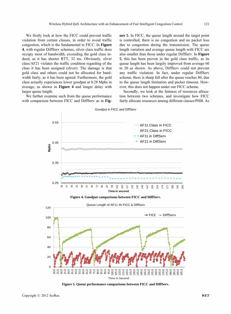
We firstly look at how the FICC could prevent traffic violation from certain classes, in order to avoid traffic congestion, which is the fundamental to FICC. In Figure 4, with regular DiffServ schemes, silver class traffic does occupy most of bandwidth, exceeding the gold class in-deed, as it has shorter RTT, 32 ms. Obviously, sliver class/AF21 violates the traffic condition regarding of the class it has been assigned (sliver). The damage is that gold class and others could not be allocated for band-width fairly, as it has been agreed. Furthermore, the gold class actually experiences lower goodput at 0.28 Mpbs in average, as shown in Figure 4 and longer delay with larger queue length.
We further examine such from the queue performance with comparison between FICC and DiffServ as in Fig-
ure 5. In FICC, the queue length around the target point is controlled; there is no congestion and no packet loss due to congestion during the transmission. The queue length variation and average queue length with FICC are also smaller than those under regular DiffServ. In Figure 5, this has been proven in the gold class traffic, as its queue length has been largely improved from average 60 to 20 as shown. As above, DiffServ could not prevent any traffic violation. In fact, under regular DiffServ scheme, there is sharp fall after the queue reaches 80, due to the queue length limitation and packet timeout. How-ever, this does not happen under our FICC scheme.
Secondly, we look at the fairness of resources alloca-tion between two schemes, and investigate how FICC fairly allocate resources among different classes/PHB. As
Goodput in FICC and DiffServ
0.25
0.35
0.45
0.55
20 27 35 42 50 57 65 72 80 87 95
102
110
117
125
132
140
147
155
162
170
177
185
192
200
Mp
bs
Time in second
AF11 Class in FICC
AF21 Class in FICC
AF11 in DiffServ
AF21 in DiffServ
Goodputs in FICC and DiffSErv
Figure 4. Goodput comparisons between FICC and DiffServ.
Queue Length of AF11 IN FICC & DiffServ
0
20
40
60
80
100
120
20.0
25.0
30.0
35.0
40.0
45.0
50.0
55.0
60.0
65.0
70.0
75.0
80.0
85.0
90.0
95.0
100.0
105.0
110.0
115.0
120.0
125.0
130.0
135.0
140.0
145.0
150.0
155.0
160.0
165.0
170.0
175.0
180.0
185.0
190.0
195.0
FICC DiffServ
Time in Second
Figure 5. Queue performance comparisons between FICC and DiffServ.
Wireless Hybrid QoS Architecture with an Enhancement of Fair Intelligent Congestion Control 122
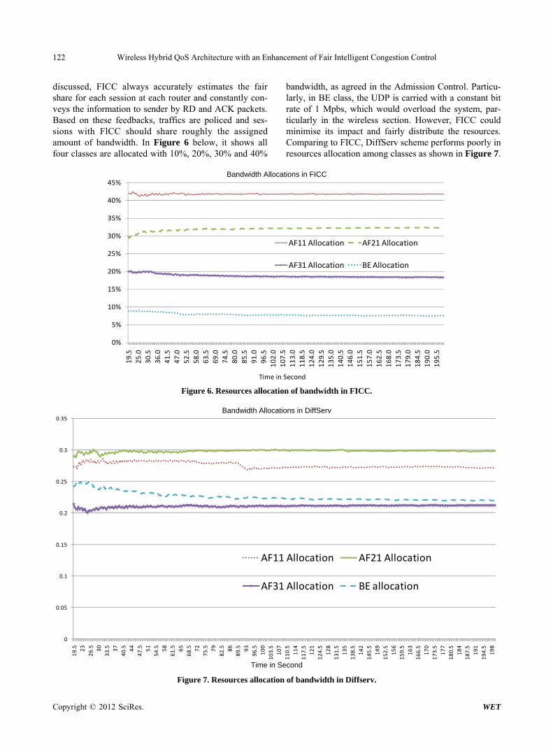
discussed, FICC always accurately estimates the fair share for each session at each router and constantly con-veys the information to sender by RD and ACK packets. Based on these feedbacks, traffics are policed and ses-sions with FlCC should share roughly the assigned amount of bandwidth. In Figure 6 below, it shows all four classes are allocated with 10%, 20%, 30% and 40%
bandwidth, as agreed in the Admission Control. Particu-larly, in BE class, the UDP is carried with a constant bit rate of 1 Mpbs, which would overload the system, par-ticularly in the wireless section. However, FICC could minimise its impact and fairly distribute the resources. Comparing to FICC, DiffServ scheme performs poorly in resources allocation among classes as shown in Figure 7.
Bandwidth Allocations in FICC
0%
5%
10%
15%
20%
25%
30%
35%
40%
45%
19.5
25.0
30.5
36.0
41.5
47.0
52.5
58.0
63.5
69.0
74.5
80.0
85.5
91.0
96.5
102.0
107.5
113.0
118.5
124.0
129.5
135.0
140.5
146.0
151.5
157.0
162.5
168.0
173.5
179.0
184.5
190.0
195.5
AF11 Allocation AF21 Allocation
AF31 Allocation BE Allocation
Time in Second
Figure 6. Resources allocation of bandwidth in FICC.
Bandwidth Allocations in DiffServ
0
0.05
0.1
0.15
0.2
0.25
0.3
0.35
19.5 23
26.5 30
33.5 37
40.5 44
47.5 51
54.5 58
61.5 65
68.5 72
75.5 79
82.5 86
89.5 93
96.5
100
103.5
107
110.5
114
117.5
121
124.5
128
131.5
135
138.5
142
145.5
149
152.5
156
159.5
163
166.5
170
173.5
177
180.5
184
187.5
191
194.5
198
AF11 Allocation AF21 Allocation
AF31 Allocation BE allocation
Time in Second
Figure 7. Resources allocation of bandwidth in Diffserv.
Copyright © 2012 SciRes. WET
Wireless Hybrid QoS Architecture with an Enhancement of Fair Intelligent Congestion Control 123
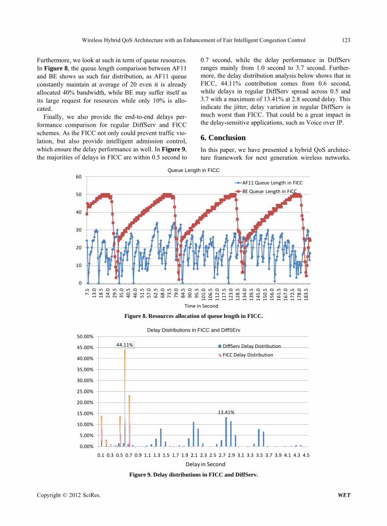
Furthermore, we look at such in term of queue resources. In Figure 8, the queue length comparison between AF11 and BE shows us such fair distribution, as AF11 queue constantly maintain at average of 20 even it is already allocated 40% bandwidth, while BE may suffer itself as its large request for resources while only 10% is allo-cated.
Finally, we also provide the end-to-end delays per-formance comparison for regular DiffServ and FICC schemes. As the FICC not only could prevent traffic vio-lation, but also provide intelligent admission control, which ensure the delay performance as well. In Figure 9, the majorities of delays in FICC are within 0.5 second to
0.7 second, while the delay performance in DiffServ ranges mainly from 1.0 second to 3.7 second. Further-more, the delay distribution analysis below shows that in FICC, 44.11% contribution comes from 0.6 second, while delays in regular DiffServ spread across 0.5 and 3.7 with a maximum of 13.41% at 2.8 second delay. This indicate the jitter, delay variation in regular DiffServ is much worst than FICC. That could be a great impact in the delay-sensitive applications, such as Voice over IP.
6. Conclusion
In this paper, we have presented a hybrid QoS architec-ture framework for next generation wireless networks.
Queue Length in FICC
0
10
20
30
40
50
60
7.5
13.0
18.5
24.0
29.5
35.0
40.5
46.0
51.5
57.0
62.5
68.0
73.5
79.0
84.5
90.0
95.5
101.0
106.5
112.0
117.5
123.0
128.5
134.0
139.5
145.0
150.5
156.0
161.5
167.0
172.5
178.0
183.5
AF11 Queue Length in FICC
BE Queue Length in FICC
Time in Second
Figure 8. Resources allocation of queue length in FICC.
Delay Distributions in FICC and DiffSErv
13.41%
44.11%
0.00%
5.00%
10.00%
15.00%
20.00%
25.00%
30.00%
35.00%
40.00%
45.00%
50.00%
0.1 0.3 0.5 0.7 0.9 1.1 1.3 1.5 1.7 1.9 2.1 2.3 2.5 2.7 2.9 3.1 3.3 3.5 3.7 3.9 4.1 4.3 4.5
DiffServ Delay Distribution
FICC Delay Distribution
Delay in Second
Figure 9. Delay distributions in FICC and DiffServ.
Copyright © 2012 SciRes. WET
Wireless Hybrid QoS Architecture with an Enhancement of Fair Intelligent Congestion Control 124
The hybrid framework applies IntServ principles of ex-plicit admission control and resource reservation locally only in the wireless access network domain, while re-maining a DiffServ-enhanced QoS control model for the core/transport part of the end-to-end path. In the context of IEEE 802.11 WLAN with 802.11e QoS extensions, a flow signalling mechanism has been designed to meet the proposed explicit admission control and resource reser-vation locally in the wireless access network. Particularly, Admission Control is implemented with a core of FICC as its algorithm in RRM, in a way that all active traffic flows can be served according to the QoS profiles nego-tiated. Simulation results have shown that FICC manages effectively the overloading scenario in the edge section, which is the resources bottleneck of the wireless access domain. Particularly, there are only a limited number of privileged connections allowed simultaneously and the pre-assigned traffic would receive the resources neces-sary to meet its QoS requirements. It prevents traffic violation from uncontrolled traffic by rejecting or down-grading a stream activation request fro background and BE, rather than to endanger the quality of all sessions; in such, guarantee is provided to those priority traffic in terms of guaranteed bandwidth allocation and specified delay. The results demonstrate that such a proposed hy-brid framework with the Fair Intelligent Congestion Control can be realized for effective end-to-end QoS delivery.
REFERENCES [1] C. N. Long, B. Li; Q. Zhang, B. Zhao, B. Yang and X. P.
Guan, “The End-to-End Rate Control in Multiple-Hop Wireless Networks: Cross-Layer Formulation and Opti-
mal Allocation,” IEEE Journal on Selected Areas in Communications, Vol. 26, No. 4, 2008, pp. 719-731. doi:10.1109/JSAC.2008.080513
[2] S. Dixit, Y. L. Guo and Z. Antoniou, “Resource Man-agement and Quality of Service in Third Generation Wireless Networks,” IEEE Communications Magazine, Vol. 39, No. 2, 2001, pp. 125-133. doi:10.1109/35.900641
[3] R. Koodli and M. Puuskari, “Supporting Packet-Data QoS in Next Generation Cellular Networks,” IEEE Communications Magazine, Vol. 39, No. 2, 2001, pp. 180-188. doi:10.1109/35.900650
[4] I. A. García-Macías, F. Rousseau, G. Berger-Sabbatel, L. Toumi and A. Duda, “Quality of Service and Mobility for the Wireless Internet,” Proceedings of the 1st Workshop on Wireless Mobile Internet, Rome, July 2001, pp. 34-42.
[5] D. B. Hoang and H. T. Phan, “End-Diff: An End-to-End QoS Architecture,” International Symposium on Commu-nications and Information Technologies, Sydney, 16-19 October 2007.
[6] H. T. Phan and D. B. Hoang, “FICC-DiffServ: A New QoS Architecture Supporting Resources Discovery, Ad-mission and Congestion Controls,” International Confer-ence on Information Technology and Applications, Syd-ney, 4-7 July 2005.
[7] H. T. Phan and D. B. Hoang, “Extension of BGP to Sup-port Multi-Domain FICC-Diffserv Architecture,” IEEE Conference on Advanced Information Networking and Applications, Vienna, 18-20 April 2006.
[8] C. Park, F. Hernández-Campos, J. S. Marron and F. D. Smith, “Long-Range Dependence in a Changing Internet Traffic Mix,” Computer Networks: The International Jour- nal of Computer and Telecommunications Networking, Vol. 48, No. 3, 2005, pp. 401-422.
Copyright © 2012 SciRes. WET