Embed Size (px)
Citation preview
AN714Wireless Home Security Implementing KEELOQ® and the
PIC® Microcontroller
00714B.book Page 1 Friday, June 10, 2011 10:23 AM
INTRODUCTIONThis application note describes a Microchip system solution for a low end/power wireless home security system. This design implements an HCS200 encoder for the intruder sensor signal encryption, one PIC12C508A PIC® MCU for sensor monitoring and RF signal initiation, HCS515 decoders for decrypting the received intruder sensor signal and a PIC16C77 PIC MCU for base station panel monitoring and control. Other support logic is included, such as a battery back-up circuit, simple single stage lead acid battery charger and external siren control, but the focus of the application is the implementation of Microchip KEELOQ® and PIC MCU products for a complete solu-tion.
Applications implementing low power RF wireless sys-tems are entering the marketplace with ever increasing acceptance, fueled in part by growing awareness of the consumer. Low power wireless systems usually trans-mit less than 1mW of power and do not require user licenses for operation. These systems operate over distances of 5 to 100 meters, depending on the appli-cation.
APPLICATIONSWireless systems are being implemented in the auto-motive, residential, personal and commercial arenas with increasing growth rates every year. Wireless sys-tems in these areas include, but are not limited to: vehi-cle alarm arming and disarming, home garage and gate door openers, home lighting control, home security and fire alarm systems, pagers, cellular phones, utility meters for near-field readings, warehouse inventory control systems and RF LANs.
In many of these applications, different levels of secu-rity are required. The level of security required is dependent on the application and customer demands. For instance, a warehouse inventory control or utility meter system may require little or no security features whereas automobile access and home security alarm systems will require more.
No matter what level of security features are imple-mented, one vulnerable link in low power RF wireless based security systems is the actual RF signal itself. An RF based system could allow for the would be intruder/thief to use a code scanning or a code grabbing system to possibly gain unauthorized access to the home, car or other less secure system.
Code scanning is an effective tool for the would be thief on systems with limited number of possible code com-binations which are found in quite a number of remote control systems. Patience, time and a hand-held micro-processor based system are all the intruder would need.
Code grabbing is a far easier way of gaining unauthor-ized access. In this method, the thief would monitor and capture the RF signal used in opening the home garage door or car. The thief would then wait until an opportune moment and then retransmit this code to gain access.
It is apparent that secure remote control systems can be implemented, if two conditions are met. The KEELOQcode hopping system meets both these conditions with ease.
1. A large number of possible combinations must be available.
A 66-bit transmission code is used to make scan-ning impossible. The 32-bit encrypted portion pro-vides for more than 4 billion code combinations. A complete scan would take 17 years! If the 34-bit fixed portion is taken into account, the time required for a complete scan jumps to 5,600 billion years.
2. The system may never respond twice to the same transmitted code.
The random code algorithm will never respond to the same code twice over several lifetimes of a typical system.
Every time a remote control button is pushed, the sys-tem will transmit a different code. These codes appear random to an outsider, therefore, there is no apparent relationship between any code and the previous or next code.
For more information on code scanning, code grabbing and an introduction to KEELOQ Code Hopping, see Technical Brief TB003, titled “An Introduction to KEELOQ Code Hopping”. Refer to the Secure Data
Author: Richard L. Fischer Microchip Technology Inc.
© 1999-2011 Microchip Technology Inc. DS00714B-page 1
AN714
00714B.book Page 2 Friday, June 10, 2011 10:23 AM
Products Handbook, Microchip document number DS40168 for additional information on KEELOQ prod-ucts.
With the arrival of the Microchip KEELOQ code hopping security products, secure remote control systems can be implemented. Microchip provides a complete secu-rity solution with a full range of encoders and decoders that incorporate the Company’s patented KEELOQ code hopping technology algorithm, allowing you to get the most advanced security technology. KEELOQ encoders are designed to be the transmitters and KEELOQ decod-ers, the receiver of secure remote keyless entry (RKE) systems.
The KEELOQ encoders feature on-chip, error corrected EEPROM for non-volatile operation and, therefore, reduce the required components normally external to the encoder. The only additional circuitry required are push buttons, battery and RF circuitry.
The KEELOQ decoders are single-chip solutions that employ normal and secure learning mechanisms, and operate over a wide voltage range. Microchip decoders are also full-featured with serial interface to PIC micro-controllers, allowing designers to integrate the decoder with system functionality.
SYSTEM OVERVIEWThe Microchip KEELOQ solution is being implemented into more and more systems requiring proven security. Systems such as, but not limited to:
• Automotive security• Gate and garage door openers• Identity tokens• Software protection• Commuter access• Industrial tagging• Livestock tagging• Parking access• Secure communications• Residential security
One simple example implementing the KEELOQ solu-tion is a home security system. The home security sys-tem described herein utilizes KEELOQ code hopping security products and a PIC microcontroller.
Some specific system design goals for this low end/power security system were:
• Wireless solution• Secure RF transmissions• Battery operation of intruder sensors for a mini-
mum of 1.5 years• Sensor module flexibility to operate with various
off-the-shelf switches for doors and windows• Microcontroller based system• Battery back-up system which provided for up to
10 hours of operation at a load draw of 400mA
• System remote arm and disarm by means of the existing garage door opener (not completely implemented in the current release)
The three main hardware components, which comprise this home security system are, the Base Station Panel, Intruder Sensor Modules and the Battery Charger/Accessory Unit.
SYSTEM DESCRIPTIONThe following sections provide a greater in depth look into each of the three main hardware components.
BASE STATION PANELThe home security base station panel provides for:
• Monitoring of sensor module initiated RF signals• User interface and system setup via the 4x4 key-
pad• Visual feedback via the 2x16 character Liquid
Crystal Display (LCD) module• On-board piezo buzzer control• Real-time clock• Monitoring of a single stage battery charger unit• Automatic DC power selection circuit
The base station can be functionally divided into 4 main components:
1. KEELOQ HCS515 decoder interface.2. Power supply switching circuit.3. Battery charger unit monitoring. 4. LCD and 4x4 keypad interface.
Base Station Operation
One of the more important tasks the base station’s microcontroller (PIC16C77) must handle, is to monitor and process the output data of the two HCS515 decod-ers. Each decoder is capable of learning up to seven sensor modules or “zones”. Within each zone, there are four different message types which the PIC16C77 must decode and process (See Appendix A, Figure 6 for the following text description).
For example, a sensor module may send an alarm, okay, test or learn transmission. In turn, the PIC16C77 reads the data (up to 80-bits) from the HCS515 decoder, evaluates the message contents and initiates the appropriate action. If an alarm condition occurs, the external siren will be activated and the internal panel piezo buzzer, (BZ1) will sound, if enabled. For any valid signal reception, such as a test, learn, sensor okay condition or alarm transmission, the history profile for that sensor module will be updated. This update con-sists of a time stamp and the sensor’s module battery status. If the sensor battery status indicates a low bat-tery state, then the base panel piezo buzzer will beep (if enabled) four times every minute until the condition is resolved. The user can determine which sensor mod-ule battery is low through proper keypad selections and individual zone battery status displayed on the LCD.
DS00714B-page 2 © 1999-2011 Microchip Technology Inc.
AN714
00714B.book Page 3 Friday, June 10, 2011 10:23 AM
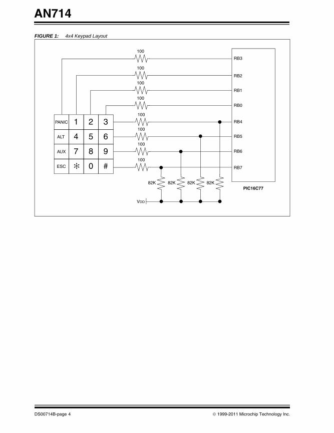
The base station can be placed into a “learn” mode so as to learn up to seven sensors (zones). Through proper keypad selections, the PIC MCU commands the HCS515 decoder into the learn mode. (See Figure 1 and Table 1). Once placed in this mode, two consecu-tive transmissions by the sensor are required to com-plete a successful learn. Once a sensor is learned, a “key” name for that zone must be selected. A menu will automatically appear on the LCD for this selection pro-cess. Currently up to 15 different key names are avail-able to choose from. The selected key name is then stored in the HCS515 EE user space.
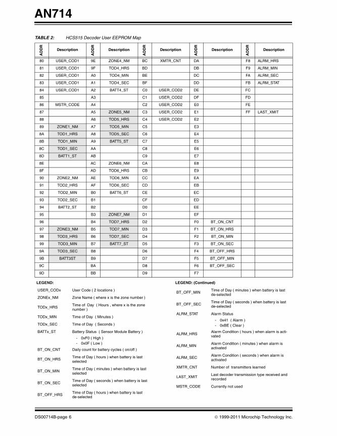
The history profile of each sensor is written to the avail-able user EEPROM in the HCS515 decoder. The total EEPROM data space available in the HCS515 is 2Kbits. System data space is 1Kbits and user memory space is the remaining 1Kbits. System data space is not accessible by the user (See Table 2 for the user EEPROM memory map). The demodulated data input into the decoders is obtained from a super regenerative data receiver referenced RF1 (See Appendix A, Figure 7, Part Number RR3-433.92 - Manufactured by Tele-controlli). The receiver has a typical RF sensitivity of -105dBm and consumes 3mA, maximum.
A Microchip microcontroller supervisory circuit, MCP130-475, is used to ensure the required system panel operating voltage range is adhered to. The brown-out feature on the PIC16C77 was not used since the base panel system operating voltage range is 4.5 to 5.5VDC.
The base station panel is designed to operate from one of two available DC input sources: the converted AC line power or the 12V lead-acid battery back-up (See Appendix A, Figure 5 for the following text description).
Both DC sources are fed into the panel via connector, JP1. From JP1, each source is input to separate adjust-able voltage regulators. The primary DC source regula-tor, U2, has its Vout set to 5.50VDC, while the secondary DC source regulator, U3, has its Vout set to 5.05VDC. Both regulator outputs are fed into separate inputs of the automatic battery back-up switch, U1.
Switch U1, is an 8-pin monolithic CMOS I.C. which senses the DC level of the two input sources and con-nects the supply of the greater potential to its output, pin 1. This is a break-before-make switch action and switching typically occurs in 50ms. Capacitor C9 is used to minimize the switching transient during the transition.
One limitation of the switch is its current switching capabilities. Maximum continuous current of the switch is exceeded by this panel design so two PNP transis-tors were added which provides for greater power switching.
The implementation of the PNP transistors is such that when the primary source is the greater of the two, pin 6 of U1, labeled “PBAR”, is effectively tied to ground
internally and therefore Q1 is biased into saturation. During this configuration, Q3 is in the off state because pin 3, labeled “SBAR”, is at hi-impedance.
When the secondary DC source is the greater of the two, Q3 will be biased into saturation and Q1 will be off. In either state, the load is handled through the transis-tors and the “VO” pin of U1 is no longer required. How-ever, the “VO” pin is configured for driving LEDs, which indicate the DC source selected.
The PIC16C77 receives status back relating to the switch selection via the signal labeled “PSOURCE”. The state of this feedback signal is active low when the primary DC source is selected, and active high if the secondary source is selected.
This power switching circuit also allows for the PIC16C77 to select the secondary source, even if the primary source is present. If the signal labeled “BAT-SEL” is asserted high by the PIC16C77, NPN transistor Q2 will be turned on and effectively reduce Vout of U2 to 1.25VDC. U1 will detect the drop and switch to the backup source. This feature can be used as a test-mechanism. Finally, VOUT of U3 supplies the voltage ref-erence, VREF, for the Analog-to-Digital module on the PIC16C77. This signal is labeled “VBAT”.
As with any home security system, it is important to pro-vide for backup power in the event of a primary source failure. A simple single stage back-up/charger unit is provided for this requirement. Based upon a load draw of 400mA, 10 hours of operation are provided for. This is a worse case scenario, which includes a 170mA (typ-ical) current draw from the external siren.
The PIC16C77 samples the battery voltage, once per minute. If the sampled battery voltage is less than ~12.75VDC, then the current limit resistor, R15, is switched in or if >12.75VDC, then bypassed (See Appendix A, Figure 9 and Appendix A, Figure 10). The user can view the battery voltage on the LCD by press-ing the appropriate keys on the 4x4 keypad. (See Table 1).
The system LCD and 4x4 keypad provide for system status feedback and setup. Status information, such as sensor module battery state, zone faults and time-of-day are displayed on the 2x16 character LCD. The LCD is updated by the PIC16C77 through data transfers on PORTD (See Appendix A, Figure 6 and Appendix A, Figure 7).
System parameter setup such as enabling the internal piezo buzzer, time-of-day setup, zone naming and alarm initiating is provided through the 4x4 keypad. System test modes are also entered through the key-pad. The keypad is interfaced to PORTB which utilizes the interrupt on change feature.
© 1999-2011 Microchip Technology Inc. DS00714B-page 3
AN714
00714B.book Page 4 Friday, June 10, 2011 10:23 AM
FIGURE 1: 4x4 Keypad Layout
1 2 3PANIC
4 5 6ALT
7 8 9AUX
0 #ESC ✻
100
100
100
100
100
100
100
100
PIC16C7782K 82K 82K 82K
VDD
RB3
RB2
RB1
RB0
RB4
RB5
RB6
RB7
DS00714B-page 4 © 1999-2011 Microchip Technology Inc.
AN714
00714B.book Page 5 Friday, June 10, 2011 10:23 AM
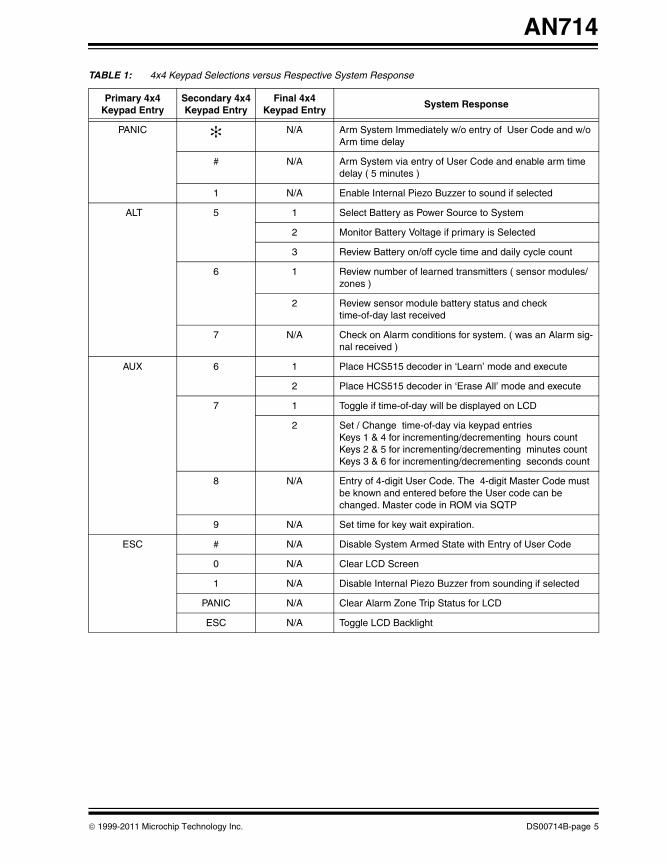
TABLE 1: 4x4 Keypad Selections versus Respective System Response
Primary 4x4Keypad Entry
Secondary 4x4Keypad Entry
Final 4x4Keypad Entry
System Response
PANIC ✻ N/A Arm System Immediately w/o entry of User Code and w/o Arm time delay
# N/A Arm System via entry of User Code and enable arm time delay ( 5 minutes )
1 N/A Enable Internal Piezo Buzzer to sound if selected
ALT 5 1 Select Battery as Power Source to System
2 Monitor Battery Voltage if primary is Selected
3 Review Battery on/off cycle time and daily cycle count
6 1 Review number of learned transmitters ( sensor modules/zones )
2 Review sensor module battery status and check time-of-day last received
7 N/A Check on Alarm conditions for system. ( was an Alarm sig-nal received )
AUX 6 1 Place HCS515 decoder in ‘Learn’ mode and execute
2 Place HCS515 decoder in ‘Erase All’ mode and execute
7 1 Toggle if time-of-day will be displayed on LCD
2 Set / Change time-of-day via keypad entriesKeys 1 & 4 for incrementing/decrementing hours count Keys 2 & 5 for incrementing/decrementing minutes countKeys 3 & 6 for incrementing/decrementing seconds count
8 N/A Entry of 4-digit User Code. The 4-digit Master Code must be known and entered before the User code can be changed. Master code in ROM via SQTP
9 N/A Set time for key wait expiration.
ESC # N/A Disable System Armed State with Entry of User Code
0 N/A Clear LCD Screen
1 N/A Disable Internal Piezo Buzzer from sounding if selected
PANIC N/A Clear Alarm Zone Trip Status for LCD
ESC N/A Toggle LCD Backlight
© 1999-2011 Microchip Technology Inc. DS00714B-page 5
AN714
00714B.book Page 6 Friday, June 10, 2011 10:23 AM
TABLE 2: HCS515 Decoder User EEPROM Map
AD
DR
Description
AD
DR
Description
AD
DR
Description
AD
DR
Description
AD
DR
Description
80 USER_COD1 9E ZONE4_NM BC XMTR_CNT DA F8 ALRM_HRS
81 USER_COD1 9F TOD4_HRS BD DB F9 ALRM_MIN
82 USER_COD1 A0 TOD4_MIN BE DC FA ALRM_SEC
83 USER_COD1 A1 TOD4_SEC BF DD FB ALRM_STAT
84 USER_COD1 A2 BATT4_ST C0 USER_COD2 DE FC
85 A3 C1 USER_COD2 DF FD
86 MSTR_CODE A4 C2 USER_COD2 E0 FE
87 A5 ZONE5_NM C3 USER_COD2 E1 FF LAST_XMIT
88 A6 TOD5_HRS C4 USER_COD2 E2
89 ZONE1_NM A7 TOD5_MIN C5 E3
8A TOD1_HRS A8 TOD5_SEC C6 E4
8B TOD1_MIN A9 BATT5_ST C7 E5
8C TOD1_SEC AA C8 E6
8D BATT1_ST AB C9 E7
8E AC ZONE6_NM CA E8
8F AD TOD6_HRS CB E9
90 ZONE2_NM AE TOD6_MIN CC EA
91 TOD2_HRS AF TOD6_SEC CD EB
92 TOD2_MIN B0 BATT6_ST CE EC
93 TOD2_SEC B1 CF ED
94 BATT2_ST B2 D0 EE
95 B3 ZONE7_NM D1 EF
96 B4 TOD7_HRS D2 F0 BT_ON_CNT
97 ZONE3_NM B5 TOD7_MIN D3 F1 BT_ON_HRS
98 TOD3_HRS B6 TOD7_SEC D4 F2 BT_ON_MIN
99 TOD3_MIN B7 BATT7_ST D5 F3 BT_ON_SEC
9A TOD3_SEC B8 D6 F4 BT_OFF_HRS
9B BATT3ST B9 D7 F5 BT_OFF_MIN
9C BA D8 F6 BT_OFF_SEC
9D BB D9 F7
LEGEND:
USER_CODx User Code ( 2 locations )
ZONEx_NM Zone Name ( where x is the zone number )
TODx_HRS Time of Day ( Hours , where x is the zone number )
TODx_MIN Time of Day ( Minutes )
TODx_SEC Time of Day ( Seconds )
BATTx_ST Battery Status ( Sensor Module Battery )
- 0xF0 ( High )- 0x0F ( Low )
BT_ON_CNT Daily count for battery cycles ( on/off )
BT_ON_HRSTime of Day ( hours ) when battery is last selected
BT_ON_MINTime of Day ( minutes ) when battery is last selected
BT_ON_SECTime of Day ( seconds ) when battery is last selected
BT_OFF_HRSTime of Day ( hours ) when battery is last de-selected
BT_OFF_MIN Time of Day ( minutes ) when battery is last de-selected
BT_OFF_SEC Time of Day ( seconds ) when battery is last de-selected
ALRM_STAT Alarm Status
- 0x41 ( Alarm )- 0xBE ( Clear )
ALRM_HRS Alarm Condition ( hours ) when alarm is acti-vated
ALRM_MIN Alarm Condition ( minutes ) when alarm is activated
ALRM_SECAlarm Condition ( seconds ) when alarm is activated
XMTR_CNT Number of transmitters learned
LAST_XMIT Last decoder transmission type received and recorded
MSTR_CODE Currently not used
LEGEND: (Continued)
DS00714B-page 6 © 1999-2011 Microchip Technology Inc.
AN714
00714B.book Page 7 Friday, June 10, 2011 10:23 AM
A 32.768KHz watch crystal is connected to the Timer1 external oscillator pins for the generation of a real time clock. Specific system data, such as alarm time, battery on/off cycle time and all valid decoded RF signals are time-tagged. The clock time is setup/changed via the 4x4 keypad and operates using the military time format, i.e., 2:30PM will display as 14:30:00, while 2:30AM will display as 02:30:00.
INTRUDER SENSOR MODULEThe four main functions of the intruder sensor modules are:
1. Intruder detection.2. Sensor battery status.3. Sensor learn.4. Sensor test.
For each of these functions, an input to the HCS200 KEELOQ encoder is asserted (active high) by the PIC12C508A. The end result is a 66-bit encrypted code word transmission, via RF, to the base station panel for decryption and processing.
In order to provide for these functions, additional logic is implemented to complement the HCS200 encoder. The logic consists of a PIC12C508A microcontroller, a relaxation type oscillator circuit, N-channel MOSFET for signal level translation, Colpitts oscillator used for the Amplitude Shift Keying (ASK) transmitter, and a few additional passive components.
See Appendix A, Figure 11 and Figure 12 for the fol-lowing sensor operation discussion.
One important operational requirement of the sensor module besides reliable signal decoding and secure RF transmission, is low current consumption. With the components selected, sensor battery life is calculated to be a minimum of 1.5 years.
Sensor operation
The KEELOQ HCS200 encoder is a perfect fit for imple-mentation into the sensor modules. The HCS200 encoder provides for:
Security
• Programmable 28-bit serial number• Programmable 64-bit encryption key• Each transmission is unique• 66-bit transmission code length• 32-bit hopping code• 28-bit serial number, 4-bit function code,
VLOW indicator transmitted• Encryption keys are read protected
Operating
• 3.5–13.0V operation• Three button inputs• Seven functions available • Selectable baud rate• Automatic code word completion
• Battery low signal transmitted to receiver• Non-volatile synchronization data
Other
• Easy to use programming interface• On-chip EEPROM• On-chip oscillator and timing components• Button inputs have internal pulldown resistors
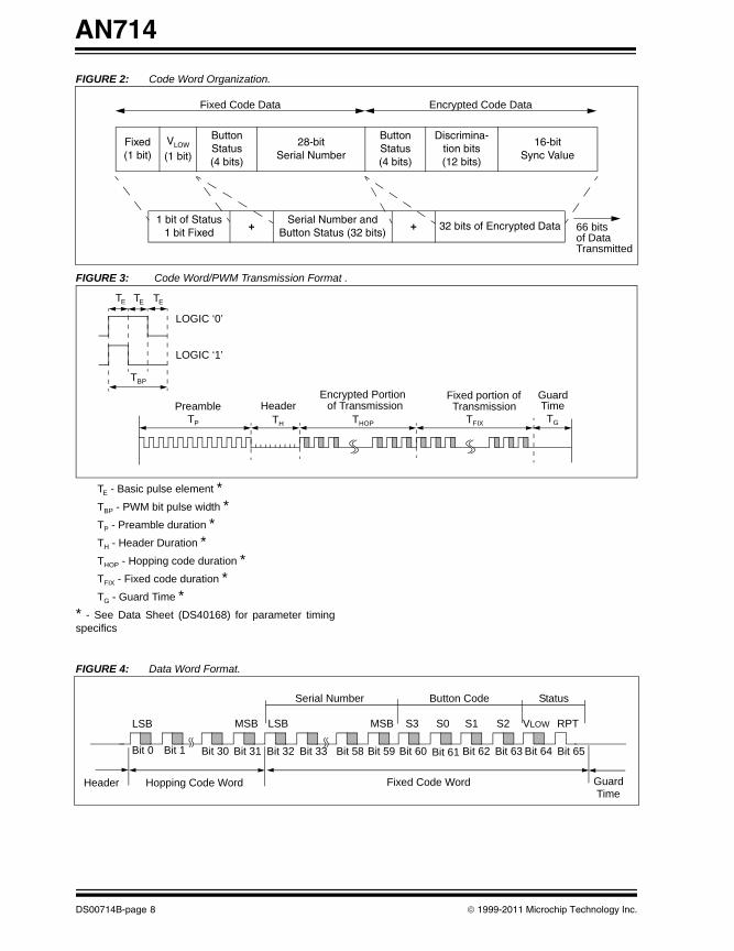
The HCS200 combines a 32-bit hopping code gener-ated by a powerful non-linear encryption algorithm, with a 28-bit serial number and 6 information bits to create a 66-bit transmission stream. The length of the trans-mission eliminates the threat of code scanning and the code hopping mechanism makes each transmission unique, thus rendering code capture-and-resend schemes useless. (See Figure 2, Figure 3 and Figure 4 for code word organization and formats).
The encryption key, serial number and configuration data are stored in EEPROM, which is not accessible via any external connection. This makes the HCS200 a very secure unit.
© 1999-2011 Microchip Technology Inc. DS00714B-page 7
AN714
00714B.book Page 8 Friday, June 10, 2011 10:23 AM
FIGURE 2: Code Word Organization.
FIGURE 3: Code Word/PWM Transmission Format .
TE - Basic pulse element *
TBP - PWM bit pulse width *TP - Preamble duration *TH - Header Duration *THOP - Hopping code duration *TFIX - Fixed code duration *TG - Guard Time *
* - See Data Sheet (DS40168) for parameter timing specifics
FIGURE 4: Data Word Format.
Fixed(1 bit)
VLOW
(1 bit)
Button Status(4 bits)
28-bitSerial Number
Button Status(4 bits)
Discrimina-tion bits(12 bits)
16-bitSync Value
1 bit of Status1 bit Fixed
+Serial Number and
Button Status (32 bits)+ 32 bits of Encrypted Data
Fixed Code Data Encrypted Code Data
66 bitsof DataTransmitted
LOGIC ‘0’
LOGIC ‘1’
Preamble HeaderEncrypted Portion of Transmission
Fixed portion ofTransmission
GuardTime
TP TH THOP TFIX TG
TBP
TE TE TE
Bit 0 Bit 1
Header
Bit 30 Bit 31 Bit 32 Bit 33 Bit 58 Bit 59
Fixed Code WordHopping Code Word Guard
LSBLSB MSB MSB S3 S0 S1 S2 VLOW RPT
Time
Serial Number Button Code Status
Bit 60 Bit 61 Bit 62 Bit 63 Bit 64 Bit 65
DS00714B-page 8 © 1999-2011 Microchip Technology Inc.
AN714
00714B.book Page 9 Friday, June 10, 2011 10:23 AM
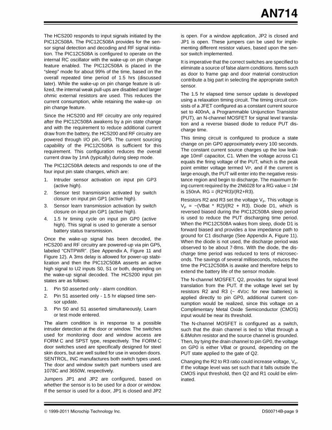
The HCS200 responds to input signals initiated by the PIC12C508A. The PIC12C508A provides for the sen-sor signal detection and decoding and RF signal initia-tion. The PIC12C508A is configured to operate on the internal RC oscillator with the wake-up on pin change feature enabled. The PIC12C508A is placed in the “sleep” mode for about 99% of the time, based on the overall repeated time period of 1.5 hrs (discussed later). While the wake-up on pin change feature is uti-lized, the internal weak pull-ups are disabled and larger ohmic external resistors are used. This reduces the current consumption, while retaining the wake-up on pin change feature.
Since the HCS200 and RF circuitry are only required after the PIC12C508A awakens by a pin state change and with the requirement to reduce additional current draw from the battery, the HCS200 and RF circuitry are powered through I/O pin, GP5. The current sourcing capability of the PIC12C508A is sufficient for this requirement. This configuration reduces the overall current draw by 1mA (typically) during sleep mode.
The PIC12C508A detects and responds to one of the four input pin state changes, which are:
1. Intruder sensor activation on input pin GP3 (active high).
2. Sensor test transmission activated by switch closure on input pin GP1 (active high).
3. Sensor learn transmission activation by switch closure on input pin GP1 (active high).
4. 1.5 hr timing cycle on input pin GP0 (active high). This signal is used to generate a sensor battery status transmission.
Once the wake-up signal has been decoded, the HCS200 and RF circuitry are powered-up via pin GP5, labeled “CNTPWR”. (See Appendix A, Figure 11 and Figure 12). A 3ms delay is allowed for power-up stabi-lization and then the PIC12C508A asserts an active high signal to U2 inputs S0, S1 or both, depending on the wake-up signal decoded. The HCS200 input pin states are as follows:
1. Pin S0 asserted only - alarm condition.2. Pin S1 asserted only - 1.5 hr elapsed time sen-
sor update.3. Pin S0 and S1 asserted simultaneously, Learn
or test mode entered.
The alarm condition is in response to a possible intruder detection at the door or window. The switches used for monitoring door and window access are FORM C and SPST type, respectively. The FORM C door switches used are specifically designed for steel skin doors, but are well suited for use in wooden doors. SENTROL, INC manufactures both switch types used. The door and window switch part numbers used are 1078C and 3650W, respectively.
Jumpers JP1 and JP2 are configured, based on whether the sensor is to be used for a door or window. If the sensor is used for a door, JP1 is closed and JP2
is open. For a window application, JP2 is closed and JP1 is open. These jumpers can be used for imple-menting different resistor values, based upon the sen-sor switch implemented.
It is imperative that the correct switches are specified to eliminate a source of false alarm conditions. Items such as door to frame gap and door material construction contribute a big part in selecting the appropriate switch sensor.
The 1.5 hr elapsed time sensor update is developed using a relaxation timing circuit. The timing circuit con-sists of a JFET configured as a constant current source set to 400nA, a Programmable Unijunction Transistor (PUT), an N-channel MOSFET for signal level transla-tion and a reverse biased diode to reduce PUT dis-charge time.
This timing circuit is configured to produce a state change on pin GP0 approximately every 100 seconds. The constant current source charges up the low leak-age 10mF capacitor, C1. When the voltage across C1 equals the firing voltage of the PUT, which is the peak point emitter voltage termed VP, and if the current is large enough, the PUT will enter into the negative resis-tance region and begin to discharge. The maximum fir-ing current required by the 2N6028 for a RG value = 1M is 150nA. RG = (R2*R3)/(R2+R3).
Resistors R2 and R3 set the voltage VP. This voltage is VP = ~(VBat * R2)/(R2 + R3). Diode D1, which is reversed biased during the PIC12C508A sleep period is used to reduce the PUT discharging time period. When the PIC12C508A wakes from sleep, diode D1 is forward biased and provides a low impedance path to ground for C1 discharge (See Appendix A, Figure 11). When the diode is not used, the discharge period was observed to be about 7-8ms. With the diode, the dis-charge time period was reduced to tens of microsec-onds. The savings of several milliseconds, reduces the time the PIC12C508A is awake and therefore helps to extend the battery life of the sensor module.
The N-channel MOSFET, Q2, provides for signal level translation from the PUT. If the voltage level set by resistors R2 and R3 (~ 4VDC for new batteries) is applied directly to pin GP0, additional current con-sumption would be realized, since this voltage on a Complimentary Metal Oxide Semiconductor (CMOS) input would be near its threshold.
The N-channel MOSFET is configured as a switch, such that the drain channel is tied to VBat through a 6.8Mohm resistor and the source channel is grounded. Then, by tying the drain channel to pin GP0, the voltage on GP0 is either VBat or ground, depending on the PUT state applied to the gate of Q2.
Changing the R2 to R3 ratio could increase voltage, VP. If the voltage level was set such that it falls outside the CMOS input threshold, then Q2 and R1 could be elim-inated.
© 1999-2011 Microchip Technology Inc. DS00714B-page 9
AN714
00714B.book Page 10 Friday, June 10, 2011 10:23 AM
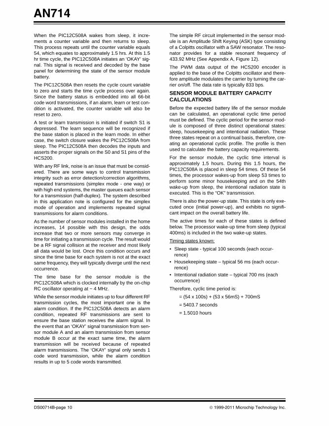
When the PIC12C508A wakes from sleep, it incre-ments a counter variable and then returns to sleep. This process repeats until the counter variable equals 54, which equates to approximately 1.5 hrs. At this 1.5 hr time cycle, the PIC12C508A initiates an ‘OKAY’ sig-nal. This signal is received and decoded by the base panel for determining the state of the sensor module battery.
The PIC12C508A then resets the cycle count variable to zero and starts the time cycle process over again. Since the battery status is embedded into all 66-bit code word transmissions, if an alarm, learn or test con-dition is activated, the counter variable will also be reset to zero.
A test or learn transmission is initiated if switch S1 is depressed. The learn sequence will be recognized if the base station is placed in the learn mode. In either case, the switch closure wakes the PIC12C508A from sleep. The PIC12C508A then decodes the inputs and asserts the proper signals on the S0 and S1 pins of the HCS200.
With any RF link, noise is an issue that must be consid-ered. There are some ways to control transmission integrity such as error detection/correction algorithms, repeated transmissions (simplex mode - one way) or with high end systems, the master queues each sensor for a transmission (half-duplex). The system described in this application note is configured for the simplex mode of operation and implements repeated signal transmissions for alarm conditions.
As the number of sensor modules installed in the home increases, 14 possible with this design, the odds increase that two or more sensors may converge in time for initiating a transmission cycle. The result would be a RF signal collision at the receiver and most likely all data would be lost. Once this condition occurs and since the time base for each system is not at the exact same frequency, they will typically diverge until the next occurrence.
The time base for the sensor module is the PIC12C508A which is clocked internally by the on-chip RC oscillator operating at ~ 4 MHz.
While the sensor module initiates up to four different RF transmission cycles, the most important one is the alarm condition. If the PIC12C508A detects an alarm condition, repeated RF transmissions are sent to ensure the base station receives the alarm signal. In the event that an ‘OKAY’ signal transmission from sen-sor module A and an alarm transmission from sensor module B occur at the exact same time, the alarm transmission will be received because of repeated alarm transmissions. The ‘OKAY’ signal only sends 1 code word transmission, while the alarm condition results in up to 5 code words transmitted.
The simple RF circuit implemented in the sensor mod-ule is an Amplitude Shift Keying (ASK) type consisting of a Colpitts oscillator with a SAW resonator. The reso-nator provides for a stable resonant frequency of 433.92 MHz (See Appendix A, Figure 12).
The PWM data output of the HCS200 encoder is applied to the base of the Colpitts oscillator and there-fore amplitude modulates the carrier by turning the car-rier on/off. The data rate is typically 833 bps.
SENSOR MODULE BATTERY CAPACITY CALCULATIONSBefore the expected battery life of the sensor module can be calculated, an operational cyclic time period must be defined. The cyclic period for the sensor mod-ule is composed of three distinct operational states: sleep, housekeeping and intentional radiation. These three states repeat on a continual basis, therefore, cre-ating an operational cyclic profile. The profile is then used to calculate the battery capacity requirements.
For the sensor module, the cyclic time interval is approximately 1.5 hours. During this 1.5 hours, the PIC12C508A is placed in sleep 54 times. Of these 54 times, the processor wakes-up from sleep 53 times to perform some minor housekeeping and on the 54th wake-up from sleep, the intentional radiation state is executed. This is the “OK” transmission.
There is also the power-up state. This state is only exe-cuted once (initial power-up), and exhibits no signifi-cant impact on the overall battery life.
The active times for each of these states is defined below. The processor wake-up time from sleep (typical 400ms) is included in the two wake-up states.
Timing states known:
• Sleep state - typical 100 seconds (each occur-rence)
• Housekeeping state – typical 56 ms (each occur-rence)
• Intentional radiation state – typical 700 ms (each occurrence)
Therefore, cyclic time period is:
= (54 x 100s) + (53 x 56mS) + 700mS
= 5403.7 seconds
= 1.5010 hours
DS00714B-page 10 © 1999-2011 Microchip Technology Inc.
AN714
00714B.book Page 11 Friday, June 10, 2011 10:23 AM
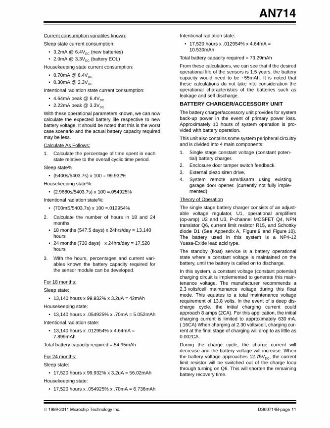
Current consumption variables known:
Sleep state current consumption:
• 3.2mA @ 6.4VDC (new batteries)• 2.0mA @ 3.3VDC (battery EOL)
Housekeeping state current consumption:
• 0.70mA @ 6.4VDC
• 0.30mA @ 3.3VDC
Intentional radiation state current consumption:
• 4.64mA peak @ 6.4VDC
• 2.22mA peak @ 3.3VDC
With these operational parameters known, we can now calculate the expected battery life respective to new battery voltage. It should be noted that this is the worst case scenario and the actual battery capacity required may be less.
Calculate As Follows:
1. Calculate the percentage of time spent in each state relative to the overall cyclic time period.
Sleep state%:
• (5400s/5403.7s) x 100 = 99.932%
Housekeeping state%:
• (2.9680s/5403.7s) x 100 =.054925%
Intentional radiation state%:
• (700mS/5403.7s) x 100 =.012954%
2. Calculate the number of hours in 18 and 24 months.
• 18 months (547.5 days) x 24hrs/day = 13,140 hours
• 24 months (730 days) x 24hrs/day = 17,520 hours
3. With the hours, percentages and current vari-ables known the battery capacity required for the sensor module can be developed.
For 18 months:
Sleep state:
• 13,140 hours x 99.932% x 3.2uA = 42mAh
Housekeeping state:
• 13,140 hours x .054925% x .70mA = 5.052mAh
Intentional radiation state:
• 13,140 hours x .012954% x 4.64mA = 7.899mAh
Total battery capacity required = 54.95mAh
For 24 months:
Sleep state:
• 17,520 hours x 99.932% x 3.2uA = 56.02mAh
Housekeeping state:
• 17,520 hours x .054925% x .70mA = 6.736mAh
Intentional radiation state:
• 17,520 hours x .012954% x 4.64mA = 10.530mAh
Total battery capacity required = 73.29mAh
From these calculations, we can see that if the desired operational life of the sensors is 1.5 years, the battery capacity would need to be ~55mAh. It is noted that these calculations do not take into consideration the operational characteristics of the batteries such as leakage and self discharge.
BATTERY CHARGER/ACCESSORY UNITThe battery charger/accessory unit provides for system back-up power in the event of primary power loss. Approximately 10 hours of system operation is pro-vided with battery operation.
This unit also contains some system peripheral circuitry and is divided into 4 main components:
1. Single stage constant voltage (constant poten-tial) battery charger.
2. Enclosure door tamper switch feedback.3. External piezo siren drive.4. System remote arm/disarm using existing
garage door opener. (currently not fully imple-mented)
Theory of Operation
The single stage battery charger consists of an adjust-able voltage regulator, U1, operational amplifiers (op-amp) U2 and U3, P-channel MOSFET Q4, NPN transistor Q6, current limit resistor R15, and Schottky diode D1 (See Appendix A, Figure 9 and Figure 10). The battery used in this system is a NP4-12 Yuasa-Exide lead acid type.
The standby (float) service is a battery operational state where a constant voltage is maintained on the battery, until the battery is called on to discharge.
In this system, a constant voltage (constant potential) charging circuit is implemented to generate this main-tenance voltage. The manufacturer recommends a 2.3 volts/cell maintenance voltage during this float mode. This equates to a total maintenance voltage requirement of 13.8 volts. In the event of a deep dis-charge cycle, the initial charging current could approach 8 amps (2CA). For this application, the initial charging current is limited to approximately 630 mA. (.16CA) When charging at 2.30 volts/cell, charging cur-rent at the final stage of charging will drop to as little as 0.002CA.
During the charge cycle, the charge current will decrease and the battery voltage will increase. When the battery voltage approaches 12.75VDC, the current limit resistor will be switched out of the charge loop through turning on Q6. This will shorten the remaining battery recovery time.
© 1999-2011 Microchip Technology Inc. DS00714B-page 11
AN714
00714B.book Page 12 Friday, June 10, 2011 10:23 AM
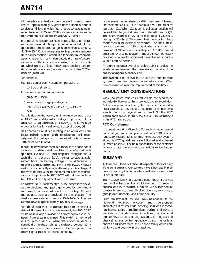
NP batteries are designed to operate in standby ser-vice for approximately 5 years based upon a normal service condition, in which float charge voltage is main-tained between 2.25 and 2.30 volts per cell in an ambi-ent temperature of approximately 20°C (68°F).
In general, to assure optimum battery life, a tempera-ture compensated charger is recommended. If the operational temperature range is between 5°C to 40°C (41°F to 104°F), it is not necessary to provide a temper-ature compensation function. If a temperature compen-sated charger is not implemented, the manufacturer recommends the maintenance voltage be set to a volt-age which closely reflects the average ambient temper-ature based upon a compensation factor of -3mV/°C for standby (float) use.
For example:
Standard center point voltage temperature is:
• 13.8 volts @ 20°C.
Estimated average temperature is:
• 29.44°C (~85°F).
Compensated charging voltage is:
• 13.8 volts + (-3mV (29.44° - 20°)) = 13.772 volts.
For this design, the battery maintenance voltage is set to 13.77 volts. Adjustable voltage regulator, U1, is adjusted to approximately 14.00VDC. This voltage accounts for the forward voltage drop of diode, D1.
This charging circuit is operating in an open loop con-figuration in the sense that the regulator output is man-ually set. If a voltage trim is required, potentiometer R18, must be adjusted.
In order to provide for some feedback to the base panel controller, a differential amplifier is configured with op-amps, U2 and U3. This amplifier configuration is such that a reference 5.1VDC zener voltage is sub-tracted from the battery voltage. This difference is amplified and routed to TB1, pin 7. The PIC16C77 base station controller will periodically sample this voltage. If this voltage falls outside the required battery mainte-nance voltage, then the PIC16C77 will indicate such on the LCD and an adjustment will be required.
An airflow fan is implemented in the accessory enclo-sure to dissipate any gases generated by the battery and provide for moderate enclosure cooling. Air inlet and exhaust ports are provided in the enclosure. The steel enclosure dimensions are 10Hx8Wx4D. The fan current draw is approximately 100 mA @ 12VDC.
For added security, an enclosure door tamper switch is utilized. If the enclosure door is opened, the PIC16C77 will be notified at pin RA2 and an alarm sequence is ini-tiated, if the system is armed. This switch is interfaced to TB5, pins 1 and 2. While the enclosure door is closed, the feedback signal developed across R3 is active low, else if the enclosure door is opened, an active high signal is observed across R3.
In the event that an alarm condition has been initiated, the base station PIC16C77 controller will turn on NPN transistor, Q1. When Q1 is on, its collector junction will be switched to ground, and this state will turn on Q3. The drain channel of Q3 is connected to TB2, pin 1 through a 56-ohm/10W current limit resistor for direct connection to the external piezo siren. The siren imple-mented operates at 12VDC, typically, with a current draw of ~170mA while exhibiting a ~116dBm sound pressure level annunciation. This circuit can be easily modified to allow for additional current draw should a louder siren be desired.
An eight conductor overall shielded cable provides the interface link between the base station panel and the battery charger/accessory unit.
This system also allows for an existing garage door system to arm and disarm the security system. (This feature is not completely implemented at this time)
REGULATORY CONSIDERATIONS While low power wireless products do not need to be individually licensed, they are subject to regulation. Before low power wireless systems can be marketed in most countries, they must be certified to comply with specific technical regulations. In the U.S., the FCC issues certification. In the U.K., it is DTI, in Germany it is the FTZ, and so on.
FCC ComplianceIt is noted here that Microchip Technology Incorporated does not guarantee compliance with any FCC or other regulatory requirements for this home security system, although FCC guidelines were followed and adhered to, when possible. It is the responsibility of the designer to ensure that the design is compliant to local stan-dards.
SUMMARYAutomobile, Home or Office. All aspects of today’s daily life require security. Consumers have a key pad in their hand, a security keypad on their wall and a smart card to get in the door.
The KEELOQ family of patented code hopping devices has quickly become the world standard for security applications by providing a simple yet highly secure solution for remote control locking devices, house keys, garage door openers, and home security.
From the low-cost, low-end HCS200 encoder to the high-end HCS410 encoder and transponder, Microchip’s KEELOQ code hopping solutions incorpo-rate high security, a small package outline, and low cost - an ideal combination for multifunctional, unidirectional remote keyless entry (RKE) systems. For logical and physical access control applications, such as cellular phones and smart cards, the KEELOQ family offers con-venience and security in one package.
DS00714B-page 12 © 1999-2011 Microchip Technology Inc.
AN714
00714B.book Page 13 Friday, June 10, 2011 10:23 AM
Microchip provides a complete security solution with a full range of encoders and decoders that incorporate the Company’s patented KEELOQ code hopping algo-rithm, allowing you to get the most advanced security technology for practically a steal.
As with all security systems, it is important that the end user understand the level of security, which is required for the assets you are wanting to protect. The strength of the security system is only as strong as the weakest link. Microchips KEELOQ Security devices are proven not be a weak link.
GLOSSARY OF TERMS
REFERENCE MATERIAL1. Application Manual, Yuasa-Exide Incorporated,
1996.2. Handbook of Batteries, 2nd Edition,
McGraw-Hill, David Linden, 1995.3. Secure Data Products Handbook, Microchip
Technology Inc., Document # DS40168, 1997 .4. Embedded Control Handbook, Microchip Tech-
nology Inc., Document # DS00092, 1997.5. PIC16C7X Data Sheet, Document # DS30390,
1997.6. FCC Code of Federal Regulations, Title 47 -
Telecommunication, Chapter I - Federal Com-munication Commission, Part 15 - Radio Fre-quency Devices, (http://frwebgate.access.gpo.gov/cgi-bin/mul-tidb.cgi).
Note: Information contained in the application note regarding device applications and the like is intended through suggestion only and may be superseded by updates. No representation or warranty is given and no liability is assumed by Microchip Technol-ogy Incorporated with respect to the accu-racy or use of such information, or infringement of patents or other intellectual property rights arising from such use or otherwise.
ASK Amplitude Shift Keying
EEPROM Electrically Erasable Programma-ble Read Only Memory
Encryption Method by which if “plain text” is known and the keying variables are known the “cipher text” can be pro-duced
KEELOQ® Algorithm
Nonlinear algorithm for generation of “cipher text”
JFET Junction Field Effect Transistor
LAN Local Area Network
LCD Liquid Crystal Display
MOSFET Metal Oxide Semiconductor Field Effect Transistor
PIC® MCU Microchip Technology Microcon-troller
PUT Programmable Unijunction Transistor
PWM Pulse Width Modulation
RKE Remote Keyless Entry
RF Radio Frequency
© 1999-2011 Microchip Technology Inc. DS00714B-page 13
AN714
00714B.book Page 14 Friday, June 10, 2011 10:23 AM
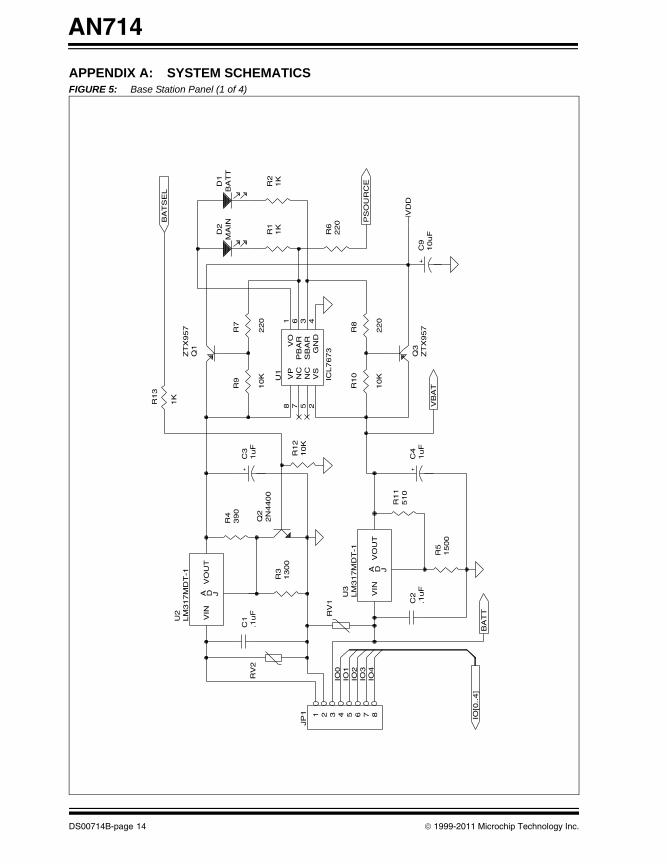
APPENDIX A: SYSTEM SCHEMATICSFIGURE 5: Base Station Panel (1 of 4)
VB
AT
15
00
R5
BA
TT
IO[0
..4
]
RV
1
IO4
IO3
IO2
IO1
IO0
.1u
FC
25
10
R1
1
LM
31
7M
DT
-1U
3
JDAV
OU
TV
IN
1u
FC
4
22
0
R8
10
K
R1
0
ZT
X9
57
Q3
10
uF
C9
VD
D
PS
OU
RC
E
BA
TT
MA
IN
22
0R
6
1K
R2
1K
R1
22
0
R7
10
K
R9 IC
L7
67
3
U1
6P
BA
R3
SB
AR
1V
O
4G
ND
2V
S
5N
C
7N
C
8V
P
10
KR
12
2N
44
00
Q2
13
00
R3
1u
FC
3
JP
1 87654321
RV
2.1
uF
C1L
M3
17
MD
T-1
U2
JDAV
OU
TV
IN
39
0R
4
ZT
X9
57
Q1
1K
R1
3B
AT
SE
L
D2
D1
DS00714B-page 14 © 1999-2011 Microchip Technology Inc.
AN714
00714B.book Page 15 Friday, June 10, 2011 10:23 AM
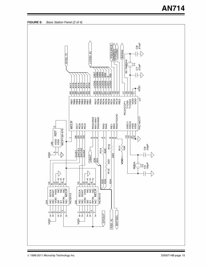
FIGURE 6: Base Station Panel (2 of 4)
33pF
C6
33pF
C5
BA
TS
EL
IO[0
..4]
10K
R17
IO4
220
R16
8M
Hz
Y2V
DD
VD
D
32.7
68K
Hz
Y1
VD
D27pF
C8
27pF
C7
PS
OU
RC
E
BZ
SIG
AR
MR
DY
LC
DB
D
E RS
LC
D0
LC
D1
RW
LC
D2
DB
4D
B5
DB
6
LC
D[0
..6]
DB
7
LC
D3
LC
D4
LC
D5
LC
D6
KY
0K
Y1
KY
2K
Y3
KY
4K
Y5
IO3
IO2
IO1
IO0
VB
AT
220
R15
220
R14
DA
TA
2C
LK
2
DA
TA
1C
LK
1
DT
OU
T
HC
S515
U5
14
NC
12
VS
S
9S
DA
T
10
SC
LK
6M
CLR
11
RF
IN
13
NC
8N
C
7N
C
5S
1
4S
0
3V
DD
2N
C
1N
CV
DD
HC
S515
U4
14
NC
12
VS
S
9S
DA
T
10
SC
LK
6M
CLR
11
RF
IN
13
NC
8N
C
7N
C
5S
1
4S
0
3V
DD
2N
C
1N
CV
DD
MC
P130-4
75
U6
2R
ST
1V
SS
3V
DD
VD
D
PIC
16C
77
U7
8R
E0
6R
A4/T
OC
KI
9R
E1
7R
A5
4R
A2
2R
A0/A
N0
3R
A1/A
N1
5R
A3/A
N3
10
RE
2
18
RC
3
23
RC
4
24
RC
5
25
RC
6
26
RC
7
17
RC
2/C
CP
1
11
VD
D
32
VD
D12
VS
S
31
VS
S
16
T1O
SI
15
T1O
SO
1M
CLR
19
RD
0
20
RD
1
21
RD
2
22
RD
3
27
RD
4
28
RD
5
29
RD
6
30
RD
7
14
OS
C2
13
OS
C1
33
RB
0
34
RB
1
35
RB
2
36
RB
3
37
RB
4
38
RB
5
39
RB
6
40
RB
7K
Y6
KY
7
KY
[0..7]
© 1999-2011 Microchip Technology Inc. DS00714B-page 15
AN714
00714B.book Page 16 Friday, June 10, 2011 10:23 AM
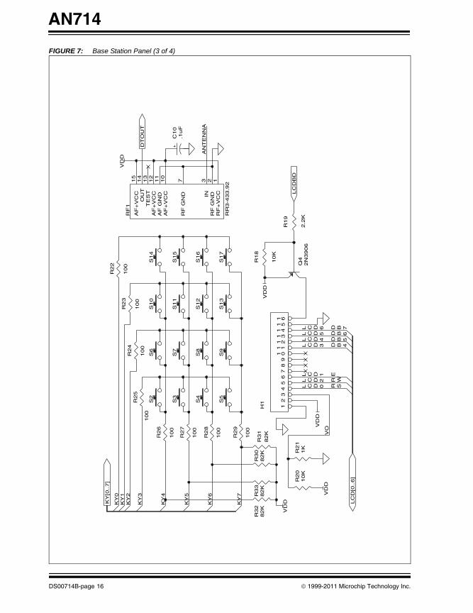
FIGURE 7: Base Station Panel (3 of 4)
7BD
6BD
5BD
4BDWR
ESR0DCL
1DCL
2DCL
3DCL
4DCL
5DCL
6DCL
VD
D
LC
D[0
..6]
VD
DV
O
KY
7 82K
R33
82K
R32
82K
R31
82K
R30
VD
D
100
R29
1K
R21
10K
R20
H1
6151
4131
2111
019
87
65
43
21
2N
3906
Q4
2.2
K
R19
10K
R18
VD
D
LC
DB
D
.1uF
C10
AN
TE
NN
A
S17
S16
S15
S13
S12
S11
S9
S8
S7
S5
S4
S3
KY
6
KY
5
100
R28
100
R27
KY
4
100
R26
KY
[0..7]
KY
0K
Y1
KY
2
KY
3100
R25
100
R24
S6
S2
100
R23
100
R22
S14
S10
RR
3-4
33.9
2
RF
115
AF
+V
CC
14
OU
T13
TE
ST
12
AF
+V
CC
11
AF
GN
D10
AF
+V
CC
7R
F G
ND
3IN
2R
F G
ND
1R
F+
VC
C
DT
OU
T
VD
D
DS00714B-page 16 © 1999-2011 Microchip Technology Inc.
AN714
00714B.book Page 17 Friday, June 10, 2011 10:23 AM
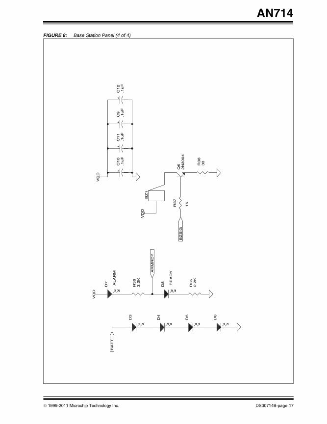
FIGURE 8: Base Station Panel (4 of 4)
D6
D5
2.2
KR
35
RE
AD
Y
BZ
SIG
33
R38
1K
R37
2N
3904
Q5
BZ
1V
DD
AR
MR
DY
D8
D4
D3
2.2
KR
36
BA
TT
D7 ALA
RM
VD
DV
DD
.1uF
C11
.1uF
C10
.1uF
C12
.1uF
C9
© 1999-2011 Microchip Technology Inc. DS00714B-page 17
AN714
00714B.book Page 18 Friday, June 10, 2011 10:23 AM
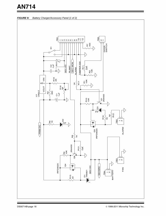
FIGURE 9: Battery Charger/Accessory Panel (1 of 2)
SW
ITC
H
ALA
RM
56
R12
TB
2 21
BA
TT
ER
Y FA
N
TB
3 21
SE
C D
C
SE
CS
RC
1N
5821
D1 T
B4 21
IRF
D9020
Q3
1KR16
D3
10K
R10
13K
R3
10K
R1
2N
4400
Q1
DO
OR
22K
R11
TB
5
2 1
400
R7
RLIM
IT
SE
C D
C
SE
C M
ON
TB
1
12
11
10
9876543215K
R18
1K
R17
ALA
RM
TA
MP
ER
SW
D2
10K
R13
1K
R8
IRF
D9020
Q4
22
R15
10K
R9 2
N4400
Q6
PR
IM D
C
1K
R6
360
R2
2K
R19
LM
317
U1
VO
UT
JDA
VIN
1uF
C1
RV
1
.1uF
C2
S1
DS00714B-page 18 © 1999-2011 Microchip Technology Inc.
AN714
00714B.book Page 19 Friday, June 10, 2011 10:23 AM
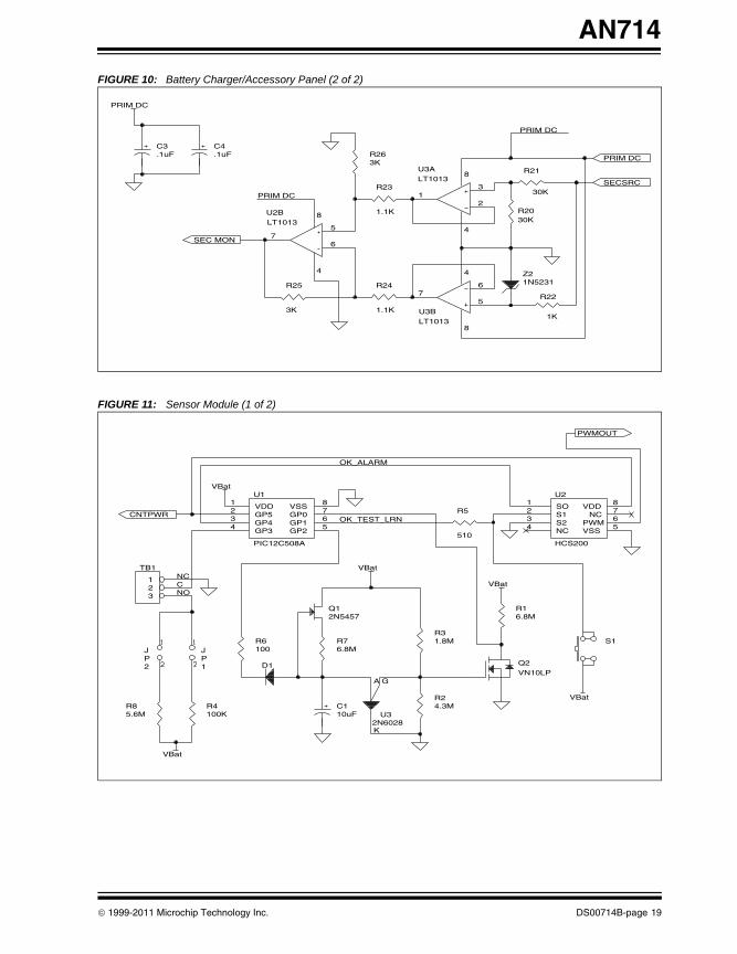
FIGURE 10: Battery Charger/Accessory Panel (2 of 2)
FIGURE 11: Sensor Module (1 of 2)
3K
R25
1.1K
R24
LT1013U3B
4
8
7 6
5
1N5231Z2
1K
R22
PRIM DC
SECSRCLT1013U3A
4
8
1 2
330K
R21
30KR20
PRIM DC
LT1013U2B
4
8
7 6
5
1.1K
R23
SEC MON
PRIM DC
.1uFC4
.1uFC3
3KR26
PRIM DC
4.3MR2
10uFC1
2N6028U35.6M
R8
VBat
100KR4
100R6
1PJ
2PJ
NO
6.8MR7
G
K
A
2N5457Q1
D1VN10LPQ2
6.8MR1
VBat
1.8MR3
VBat
S1
HCS200
U28
VDD7
NC6
PWM5
VSS4
NC
3S2
2S1
1SO
510
R5
PIC12C508A
U1 8
VSS 7
GP0 6
GP1 5
GP2 4
GP3
3GP4
2GP5
1VDD
VBat
OK_TEST_LRN
TB1
321
VBat
CNC
CNTPWR
OK_ALARM
PWMOUT
© 1999-2011 Microchip Technology Inc. DS00714B-page 19
AN714
00714B.book Page 20 Friday, June 10, 2011 10:23 AM
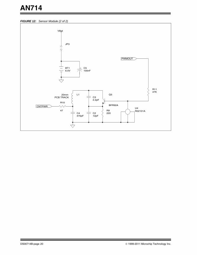
FIGURE 12: Sensor Module (2 of 2)
CNTPWR
PCB TRACKL1
470pFC4
47
R102.2pFC3
12pFC2
20mm
R02101AU4
BFR92A
Q3
220R9
47KR11
PWMOUT
6.0VBT1
100nFC5
VBat
JP3
DS00714B-page 20 © 1999-2011 Microchip Technology Inc.
AN714
00714B.book Page 21 Friday, June 10, 2011 10:23 AM
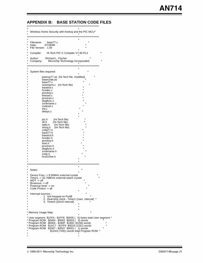
APPENDIX B: BASE STATION CODE FILES/********************************************************************** ** Wireless Home Security with Keeloq and the PIC MCU** ************************************************************************ ** Filename: base77.c ** Date: 07/18/99 ** File Version: 1.00 ** ** Compiler: Hi-Tech PIC C Compiler V7.83 PL3 ** ** Author: Richard L. Fischer ** Company: Microchip Technology Incorporated ** ************************************************************************ ** System files required: ** ** powrup77.as (Hi-Tech file, modified) ** basecode.as ** base77.c ** newmprnt.c (Hi-Tech file) ** baselcd.c ** hcsdec.c ** prockey.c ** timeset.c ** proctran.c ** diagfunc.c ** zonename.c ** codesel.c ** init.c ** delays.c ** ** ** pic.h (Hi-Tech file) ** sfr.h (Hi-Tech file) ** stdio.h (Hi-Tech file) ** string.h (Hi-Tech file) ** cnfig77.h ** base77.h ** baselcd.h ** hcsdec.h ** prockey.h ** time.h ** proctran.h ** diagfunc.h ** zonename.h ** code.h ** hcs515ee.h ** ** ************************************************************************ ** Notes: ** ** Device Fosc -> 8.00MHz external crystal ** Timer1 -> 32.768KHz external watch crystal ** WDT -> off ** Brownout -> off ** Powerup timer -> on ** Code Protect -> all ** ** Interrupt sources - ** 1. 4x4 Keypad on PortB ** 2. Real-time clock - Timer1 (1sec. interval) ** 3. Timer0 (32mS interval) ** ** ** ** Memory Usage Map: ** ** User segment $1FFA - $1FFE $0005 ( 5) bytes total User segment ** Program ROM $0000 - $0002 $0003 ( 3) words ** Program ROM $0004 - $180F $180C (6156) words ** Program ROM $1AC7 - $1FF9 $0533 (1331) words ** Program ROM $2007 - $2007 $0001 ( 1) words ** $1D43 (7491) words total Program ROM ** ** *
© 1999-2011 Microchip Technology Inc. DS00714B-page 21
AN714
00714B.book Page 22 Friday, June 10, 2011 10:23 AM
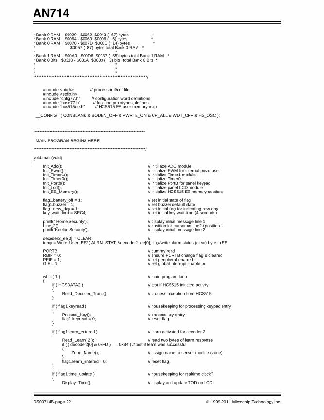
* Bank 0 RAM $0020 - $0062 $0043 ( 67) bytes ** Bank 0 RAM $0064 - $0069 $0006 ( 6) bytes ** Bank 0 RAM $0070 - $007D $000E ( 14) bytes ** $0057 ( 87) bytes total Bank 0 RAM ** ** Bank 1 RAM $00A0 - $00D6 $0037 ( 55) bytes total Bank 1 RAM ** Bank 0 Bits $0318 - $031A $0003 ( 3) bits total Bank 0 Bits ** ** ** **********************************************************************/
#include <pic.h> // processor if/def file#include <stdio.h>#include “cnfig77.h” // configuration word definitions#include “base77.h” // function prototypes, defines.#include “hcs515ee.h” // HCS515 EE user memory map
__CONFIG ( CONBLANK & BODEN_OFF & PWRTE_ON & CP_ALL & WDT_OFF & HS_OSC );
/*******************************************************************
MAIN PROGRAM BEGINS HERE
********************************************************************/
void main(void){
Init_Adc(); // initiliaze ADC moduleInit_Pwm(); // initialize PWM for internal piezo useInit_Timer1(); // initialize Timer1 moduleInit_Timer0(); // initialize Timer0Init_Portb(); // initialize PortB for panel keypad Init_Lcd(); // initialize panel LCD moduleInit_EE_Memory(); // initialize HCS515 EE memory sections
flag1.battery_off = 1; // set initial state of flag flag1.buzzer = 1; // set buzzer default stateflag1.new_day = 1; // set initial flag for indicating new daykey_wait_limit = SEC4; // set initial key wait time (4 seconds)
printf(“ Home Security”); // display initial message line 1Line_2(); // position lcd cursor on line2 / position 1printf(“Keeloq Security”); // display initial message line 2
decoder2_ee[0] = CLEAR; // temp = Write_User_EE2( ALRM_STAT, &decoder2_ee[0], 1 );//write alarm status (clear) byte to EE
PORTB; // dummy readRBIF = 0; // ensure PORTB change flag is clearedPEIE = 1; // set peripheral enable bitGIE = 1; // set global interrupt enable bit
while( 1 ) // main program loop{
if ( HCSDATA2 ) // test if HCS515 initiated activity{
Read_Decoder_Trans(); // process reception from HCS515}
if ( flag1.keyread ) // housekeeping for processing keypad entry{
Process_Key(); // process key entry flag1.keyread = 0; // reset flag
}
if ( flag1.learn_entered ) // learn activated for decoder 2{
Read_Learn( 2 ); // read two bytes of learn responseif ( ( decoder2[0] & 0xFD ) == 0x84 ) // test if learn was successful{
Zone_Name(); // assign name to sensor module (zone)}flag1.learn_entered = 0; // reset flag
}
if ( flag1.time_update ) // housekeeping for realtime clock?{
Display_Time(); // display and update TOD on LCD
DS00714B-page 22 © 1999-2011 Microchip Technology Inc.
AN714
00714B.book Page 23 Friday, June 10, 2011 10:23 AM
}
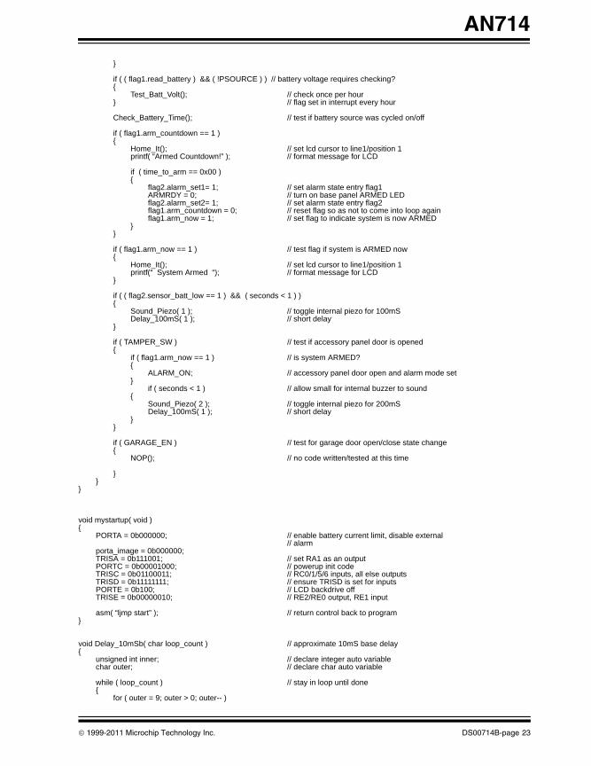
if ( ( flag1.read_battery ) && ( !PSOURCE ) ) // battery voltage requires checking?{
Test_Batt_Volt(); // check once per hour} // flag set in interrupt every hour
Check_Battery_Time(); // test if battery source was cycled on/off
if ( flag1.arm_countdown == 1 ){
Home_It(); // set lcd cursor to line1/position 1printf( “Armed Countdown!” ); // format message for LCD
if ( time_to_arm == 0x00 ) {
flag2.alarm_set1= 1; // set alarm state entry flag1ARMRDY = 0; // turn on base panel ARMED LEDflag2.alarm_set2= 1; // set alarm state entry flag2flag1.arm_countdown = 0; // reset flag so as not to come into loop againflag1.arm_now = 1; // set flag to indicate system is now ARMED
}}
if ( flag1.arm_now == 1 ) // test flag if system is ARMED now{
Home_It(); // set lcd cursor to line1/position 1printf(“ System Armed “); // format message for LCD
}
if ( ( flag2.sensor_batt_low == 1 ) && ( seconds < 1 ) ){
Sound_Piezo( 1 ); // toggle internal piezo for 100mS Delay_100mS( 1 ); // short delay
}
if ( TAMPER_SW ) // test if accessory panel door is opened{
if ( flag1.arm_now == 1 ) // is system ARMED?{
ALARM_ON; // accessory panel door open and alarm mode set }
if ( seconds < 1 ) // allow small for internal buzzer to sound{
Sound_Piezo( 2 ); // toggle internal piezo for 200mS Delay_100mS( 1 ); // short delay
}}
if ( GARAGE_EN ) // test for garage door open/close state change{
NOP(); // no code written/tested at this time
}}
}
void mystartup( void ){
PORTA = 0b000000; // enable battery current limit, disable external// alarm
porta_image = 0b000000;TRISA = 0b111001; // set RA1 as an outputPORTC = 0b00001000; // powerup init codeTRISC = 0b01100011; // RC0/1/5/6 inputs, all else outputsTRISD = 0b11111111; // ensure TRISD is set for inputsPORTE = 0b100; // LCD backdrive offTRISE = 0b00000010; // RE2/RE0 output, RE1 input
asm( “ljmp start” ); // return control back to program}
void Delay_10mSb( char loop_count ) // approximate 10mS base delay{
unsigned int inner; // declare integer auto variablechar outer; // declare char auto variable
while ( loop_count ) // stay in loop until done{
for ( outer = 9; outer > 0; outer-- )
© 1999-2011 Microchip Technology Inc. DS00714B-page 23
AN714
00714B.book Page 24 Friday, June 10, 2011 10:23 AM
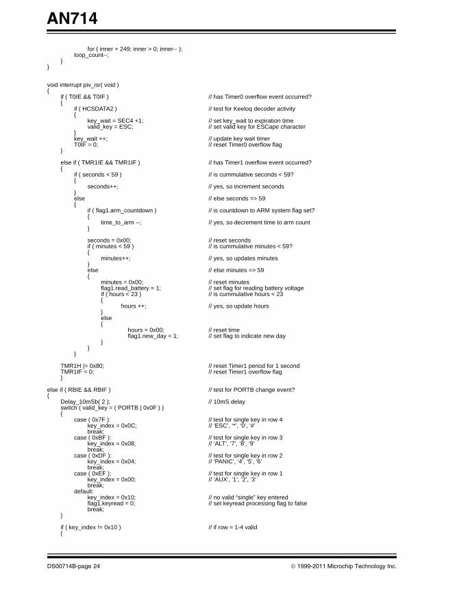
for ( inner = 249; inner > 0; inner-- );loop_count--;
}}
void interrupt piv_isr( void ){
if ( T0IE && T0IF ) // has Timer0 overflow event occurred?{
if ( HCSDATA2 ) // test for Keeloq decoder activity{
key_wait = SEC4 +1; // set key_wait to expiration timevalid_key = ESC; // set valid key for ESCape character
}key_wait ++; // update key wait timerT0IF = 0; // reset Timer0 overflow flag
}
else if ( TMR1IE && TMR1IF ) // has Timer1 overflow event occurred?{
if ( seconds < 59 ) // is cummulative seconds < 59?{
seconds++; // yes, so increment seconds}else // else seconds => 59 {
if ( flag1.arm_countdown ) // is countdown to ARM system flag set?{
time_to_arm --; // yes, so decrement time to arm count}
seconds = 0x00; // reset secondsif ( minutes < 59 ) // is cummulative minutes < 59?{
minutes++; // yes, so updates minutes }else // else minutes => 59{
minutes = 0x00; // reset minutesflag1.read_battery = 1; // set flag for reading battery voltageif ( hours < 23 ) // is cummulative hours < 23{
hours ++; // yes, so update hours}else{
hours = 0x00; // reset timeflag1.new_day = 1; // set flag to indicate new day
} }
}
TMR1H |= 0x80; // reset Timer1 period for 1 secondTMR1IF = 0; // reset Timer1 overflow flag}
else if ( RBIE && RBIF ) // test for PORTB change event?{
Delay_10mSb( 2 ); // 10mS delayswitch ( valid_key = ( PORTB | 0x0F ) ){
case ( 0x7F ): // test for single key in row 4key_index = 0x0C; // ‘ESC’, ‘*’, ‘0’, ‘#’break;
case ( 0xBF ): // test for single key in row 3key_index = 0x08; // ‘ALT’, ‘7’, ‘8’, ‘9’break;
case ( 0xDF ): // test for single key in row 2key_index = 0x04; // ‘PANIC’, ‘4’, ‘5’, ‘6’break;
case ( 0xEF ): // test for single key in row 1key_index = 0x00; // ‘AUX’, ‘1’, ‘2’, ‘3’break;
default:key_index = 0x10; // no valid “single” key enteredflag1.keyread = 0; // set keyread processing flag to falsebreak;
}
if ( key_index != 0x10 ) // if row = 1-4 valid{
DS00714B-page 24 © 1999-2011 Microchip Technology Inc.
AN714
00714B.book Page 25 Friday, June 10, 2011 10:23 AM
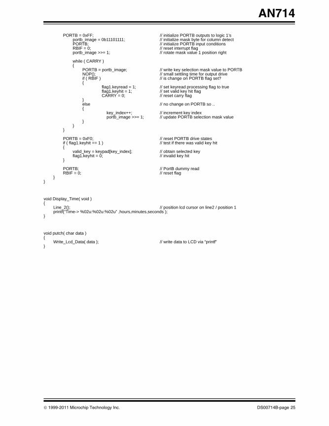
PORTB = 0xFF; // initialize PORTB outputs to logic 1’sportb_image = 0b11101111; // initialize mask byte for column detectPORTB; // initialize PORTB input conditions RBIF = 0; // reset interrupt flagportb_image >>= 1; // rotate mask value 1 position right
while ( CARRY ){
PORTB = portb_image; // write key selection mask value to PORTBNOP(); // small settling time for output driveif ( RBIF ) // is change on PORTB flag set?{
flag1.keyread = 1; // set keyread processing flag to trueflag1.keyhit = 1; // set valid key hit flagCARRY = 0; // reset carry flag
}else // no change on PORTB so ..{
key_index++; // increment key indexportb_image >>= 1; // update PORTB selection mask value
}}
}
PORTB = 0xF0; // reset PORTB drive statesif ( flag1.keyhit == 1 ) // test if there was valid key hit{
valid_key = keypad[key_index]; // obtain selected keyflag1.keyhit = 0; // invalid key hit
}
PORTB; // PortB dummy readRBIF = 0; // reset flag
}}
void Display_Time( void ){
Line_2(); // position lcd cursor on line2 / position 1 printf(“Time-> %02u:%02u:%02u” ,hours,minutes,seconds );
}
void putch( char data ){
Write_Lcd_Data( data ); // write data to LCD via “printf”}
© 1999-2011 Microchip Technology Inc. DS00714B-page 25
AN714
00714B.book Page 26 Friday, June 10, 2011 10:23 AM
/********************************************************************** ** Filename: base77.h ** Date: 07/18/99 ** File Version: 1.00 ** ** Compiler: Hi-Tech PIC C Compiler V7.83 PL3 ** **********************************************************************/
// ROM ARRAY STORAGE DEFINED HERE
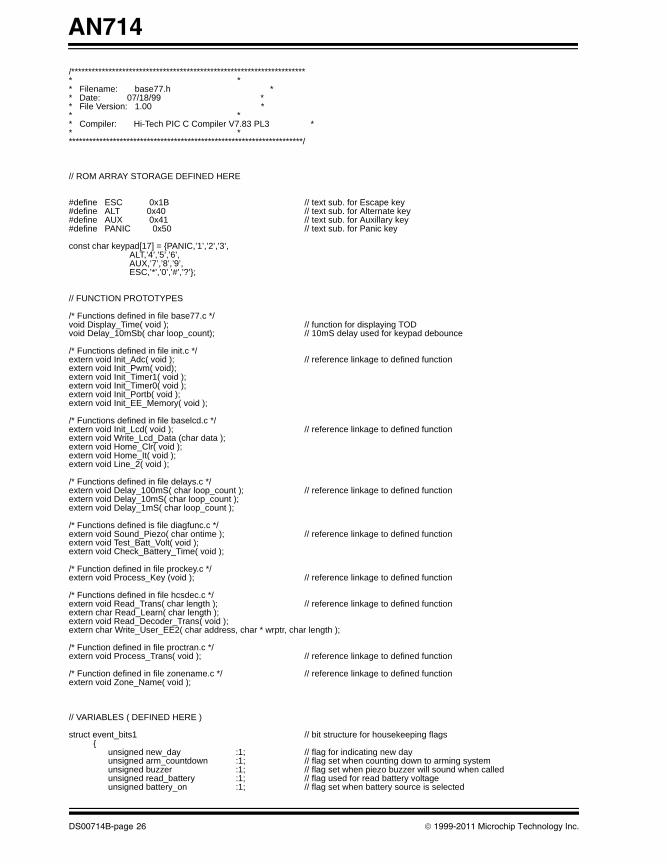
#define ESC 0x1B // text sub. for Escape key#define ALT 0x40 // text sub. for Alternate key#define AUX 0x41 // text sub. for Auxillary key#define PANIC 0x50 // text sub. for Panic key
const char keypad[17] = {PANIC,’1’,’2’,’3’, ALT,’4’,’5’,’6’, AUX,’7’,’8’,’9’, ESC,’*’,’0’,’#’,’?’};
// FUNCTION PROTOTYPES
/* Functions defined in file base77.c */void Display_Time( void ); // function for displaying TODvoid Delay_10mSb( char loop_count); // 10mS delay used for keypad debounce
/* Functions defined in file init.c */extern void Init_Adc( void ); // reference linkage to defined functionextern void Init_Pwm( void);extern void Init_Timer1( void );extern void Init_Timer0( void );extern void Init_Portb( void );extern void Init_EE_Memory( void );
/* Functions defined in file baselcd.c */extern void Init_Lcd( void ); // reference linkage to defined functionextern void Write_Lcd_Data (char data );extern void Home_Clr( void );extern void Home_It( void );extern void Line_2( void );
/* Functions defined in file delays.c */extern void Delay_100mS( char loop_count ); // reference linkage to defined functionextern void Delay_10mS( char loop_count );extern void Delay_1mS( char loop_count );
/* Functions defined is file diagfunc.c */ extern void Sound_Piezo( char ontime ); // reference linkage to defined functionextern void Test_Batt_Volt( void );extern void Check_Battery_Time( void );
/* Function defined in file prockey.c */extern void Process_Key (void ); // reference linkage to defined function
/* Functions defined in file hcsdec.c */extern void Read_Trans( char length ); // reference linkage to defined functionextern char Read_Learn( char length );extern void Read_Decoder_Trans( void );extern char Write_User_EE2( char address, char * wrptr, char length );
/* Function defined in file proctran.c */extern void Process_Trans( void ); // reference linkage to defined function
/* Function defined in file zonename.c */ // reference linkage to defined functionextern void Zone_Name( void );
// VARIABLES ( DEFINED HERE )
struct event_bits1 // bit structure for housekeeping flags {
unsigned new_day :1; // flag for indicating new dayunsigned arm_countdown :1; // flag set when counting down to arming system unsigned buzzer :1; // flag set when piezo buzzer will sound when called unsigned read_battery :1; // flag used for read battery voltageunsigned battery_on :1; // flag set when battery source is selected
DS00714B-page 26 © 1999-2011 Microchip Technology Inc.
AN714
00714B.book Page 27 Friday, June 10, 2011 10:23 AM
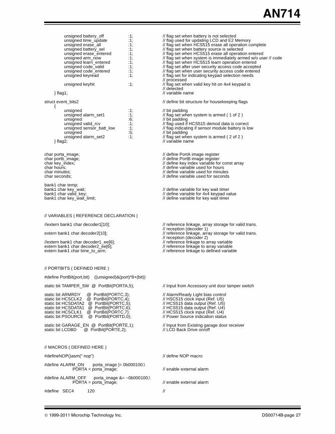
unsigned battery_off :1; // flag set when battery is not selectedunsigned time_update :1; // flag used for updating LCD and E2 Memory unsigned erase_all :1; // flag set when HCS515 erase all operation completeunsigned battery_sel :1; // flag set when battery source is selectedunsigned erase_entered :1; // flag set when HCS515 erase all operation enteredunsigned arm_now :1; // flag set when system is immediately armed w/o user // codeunsigned learn_entered :1; // flag set when HCS515 learn operation enteredunsigned code_valid :1; // flag set after user security access code acceptedunsigned code_entered :1; // flag set when user security access code enteredunsigned keyread :1; // flag set for indicating keypad selection needs
// processedunsigned keyhit :1; // flag set when valid key hit on 4x4 keypad is
// detected} flag1; // variable name
struct event_bits2 // define bit structure for housekeeping flags{ unsigned :1; // bit padding
unsigned alarm_set1 :1; // flag set when system is armed ( 1 of 2 )unsigned :6; // bit padding unsigned valid_rcv :1; // flag used if HCS515 demod data is correct unsigned sensor_batt_low :1; // flag indicating if sensor module battery is lowunsigned :5; // bit paddingunsigned alarm_set2 :1; // flag set when system is armed ( 2 of 2 )
} flag2; // variable name
char porta_image; // define PortA image registerchar portb_image; // define PortB image registerchar key_index; // define key index variable for const arraychar hours; // define variable used for hourschar minutes; // define variable used for minuteschar seconds; // define variable used for seconds
bank1 char temp;bank1 char key_wait; // define variable for key wait timerbank1 char valid_key; // define variable for 4x4 keypad valuebank1 char key_wait_limit; // define variable for key wait timer
// VARIABLES ( REFERENCE DECLARATION )
//extern bank1 char decoder1[10]; // reference linkage, array storage for valid trans.// reception (decoder 1)
extern bank1 char decoder2[10]; // reference linkage, array storage for valid trans.// reception (decoder 2)
//extern bank1 char decoder1_ee[6]; // reference linkage to array variable extern bank1 char decoder2_ee[6]; // reference linkage to array variableextern bank1 char time_to_arm; // reference linkage to defined variable
// PORTBITS ( DEFINED HERE )
#define PortBit(port,bit) ((unsigned)&(port)*8+(bit))
static bit TAMPER_SW @ PortBit(PORTA,5); // Input from Accessory unit door tamper switch
static bit ARMRDY @ PortBit(PORTC,3); // Alarm/Ready Light bias controlstatic bit HCSCLK2 @ PortBit(PORTC,4); // HSC515 clock input (Ref. U5)static bit HCSDATA2 @ PortBit(PORTC,5); // HCS515 data output (Ref. U5)static bit HCSDATA1 @ PortBit(PORTC,6); // HCS515 data output (Ref. U4)static bit HCSCLK1 @ PortBit(PORTC,7); // HCS515 clock input (Ref. U4)static bit PSOURCE @ PortBit(PORTD,0); // Power Source indication status
static bit GARAGE_EN @ PortBit(PORTE,1); // Input from Existing garage door receiverstatic bit LCDBD @ PortBit(PORTE,2); // LCD Back Drive on/off
// MACROS ( DEFINED HERE )
#defineNOP()asm(“ nop”) // define NOP macro
#define ALARM_ON porta_image |= 0b000100;\ PORTA = porta_image; // enable external alarm
#define ALARM_OFF porta_image &= ~0b000100;\ PORTA = porta_image; // enable external alarm
#define SEC4 120 //
© 1999-2011 Microchip Technology Inc. DS00714B-page 27
AN714
00714B.book Page 28 Friday, June 10, 2011 10:23 AM
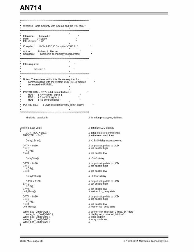
/********************************************************************** ** Wireless Home Security with Keeloq and the PIC MCU** ************************************************************************ ** Filename: baselcd.c ** Date: 07/18/99 ** File Version: 1.00 ** ** Compiler: Hi-Tech PIC C Compiler V7.83 PL3 ** ** Author: Richard L. Fischer ** Company: Microchip Technology Incorporated ** ************************************************************************ ** Files required: ** ** baselcd.h ** ************************************************************************ ** Notes: The routines within this file are required for ** communicating with the system LCD (2x16) module ** connected to PORTD. ** ** ** PORTD: RD4 - RD7 ( 4-bit data interface ) ** RD3 - ( R/W control signal ) ** RD2 - ( E control signal ) ** RD1 - ( RS control signal ) ** ** PORTE: RE2 - ( LCD backlight on/off / 60mA draw ) ** ** **********************************************************************/
#include “baselcd.h” // function prototypes, defines..
void Init_Lcd( void ) // initialize LCD display{
CONTROL = 0x01; // initial state of control lines TRISCTRL = 0x01; // initialize control lines
Delay15ms(); // ~15mS delay upon powerup
DATA = 0x30; // output setup data to LCD E = 1; // set enable high
NOP(); E = 0; // set enable low
Delay5ms(); // ~5mS delay
DATA = 0x30; // output setup data to LCD E = 1; // set enable high
NOP(); E = 0; // set enable low
Delay200us(); // ~200uS delay
DATA = 0x30; // output setup data to LCD E = 1; // set enable high
NOP(); E = 0; // set enable low Lcd_Busy(); // test for lcd_busy state
DATA = 0x20; // output setup data to LCD E = 1; // set enable high
NOP(); E = 0; // set enable low Lcd_Busy(); // test for lcd_busy state
Write_Lcd_Cmd( 0x28 ); // define 4 bit interface, 2 lines. 5x7 dots Write_Lcd_Cmd( 0x0C ); // display on, cursor on, blink off Write_Lcd_Cmd( 0x01 ); // clear display Write_Lcd_Cmd( 0x06 ); // entry mode set.. Write_Lcd_Cmd( 0x28 ); //}
DS00714B-page 28 © 1999-2011 Microchip Technology Inc.
AN714
00714B.book Page 29 Friday, June 10, 2011 10:23 AM
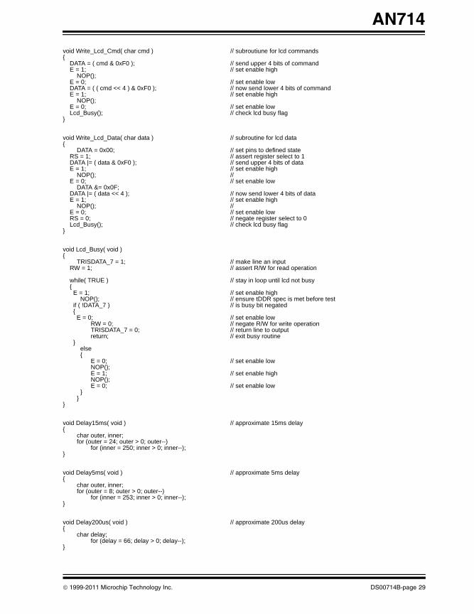
void Write_Lcd_Cmd( char cmd ) // subroutiune for lcd commands{ DATA = ( cmd & 0xF0 ); // send upper 4 bits of command E = 1; // set enable high
NOP(); E = 0; // set enable low DATA = ( ( cmd << 4 ) & 0xF0 ); // now send lower 4 bits of command E = 1; // set enable high
NOP(); E = 0; // set enable low Lcd_Busy(); // check lcd busy flag}
void Write_Lcd_Data( char data ) // subroutine for lcd data{
DATA = 0x00; // set pins to defined state RS = 1; // assert register select to 1 DATA |= ( data & 0xF0 ); // send upper 4 bits of data E = 1; // set enable high
NOP(); // E = 0; // set enable low
DATA &= 0x0F; DATA |= ( data << 4 ); // now send lower 4 bits of data E = 1; // set enable high
NOP(); // E = 0; // set enable low RS = 0; // negate register select to 0 Lcd_Busy(); // check lcd busy flag}
void Lcd_Busy( void ){
TRISDATA_7 = 1; // make line an input RW = 1; // assert R/W for read operation
while( TRUE ) // stay in loop until lcd not busy { E = 1; // set enable high
NOP(); // ensure tDDR spec is met before test if ( !DATA_7 ) // is busy bit negated { E = 0; // set enable low
RW = 0; // negate R/W for write operationTRISDATA_7 = 0; // return line to outputreturn; // exit busy routine
} else {
E = 0; // set enable low NOP();E = 1; // set enable highNOP();E = 0; // set enable low
}}
}
void Delay15ms( void ) // approximate 15ms delay{
char outer, inner;for (outer = 24; outer > 0; outer--)
for (inner = 250; inner > 0; inner--);}
void Delay5ms( void ) // approximate 5ms delay{
char outer, inner;for (outer = 8; outer > 0; outer--)
for (inner = 253; inner > 0; inner--);}
void Delay200us( void ) // approximate 200us delay{
char delay;for (delay = 66; delay > 0; delay--);
}
© 1999-2011 Microchip Technology Inc. DS00714B-page 29
AN714
00714B.book Page 30 Friday, June 10, 2011 10:23 AM
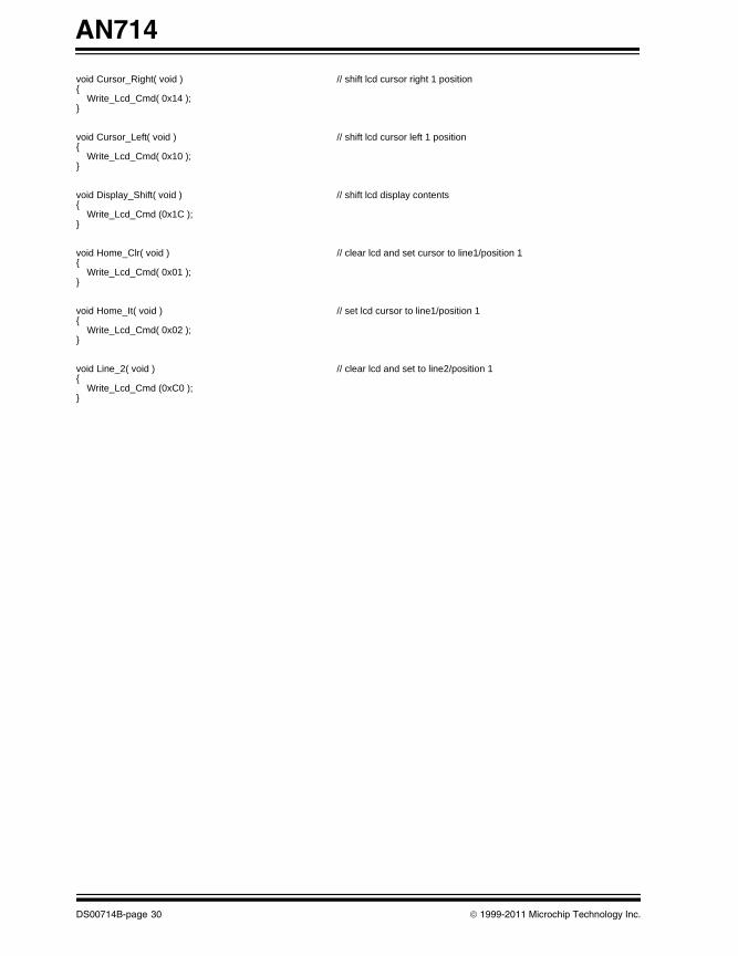
void Cursor_Right( void ) // shift lcd cursor right 1 position{ Write_Lcd_Cmd( 0x14 );}
void Cursor_Left( void ) // shift lcd cursor left 1 position{ Write_Lcd_Cmd( 0x10 );}
void Display_Shift( void ) // shift lcd display contents{ Write_Lcd_Cmd (0x1C );}
void Home_Clr( void ) // clear lcd and set cursor to line1/position 1 { Write_Lcd_Cmd( 0x01 );}
void Home_It( void ) // set lcd cursor to line1/position 1{ Write_Lcd_Cmd( 0x02 );}
void Line_2( void ) // clear lcd and set to line2/position 1{ Write_Lcd_Cmd (0xC0 );}
DS00714B-page 30 © 1999-2011 Microchip Technology Inc.
AN714
00714B.book Page 31 Friday, June 10, 2011 10:23 AM
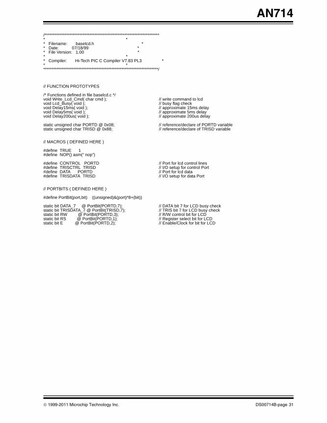
/********************************************************************** ** Filename: baselcd.h ** Date: 07/18/99 ** File Version: 1.00 ** ** Compiler: Hi-Tech PIC C Compiler V7.83 PL3 ** **********************************************************************/
// FUNCTION PROTOTYPES
/* Functions defined in file baselcd.c */void Write_Lcd_Cmd( char cmd ); // write command to lcdvoid Lcd_Busy( void ); // busy flag checkvoid Delay15ms( void ); // approximate 15ms delayvoid Delay5ms( void ); // approximate 5ms delayvoid Delay200us( void ); // approximate 200us delay
static unsigned char PORTD @ 0x08; // reference/declare of PORTD variablestatic unsigned char TRISD @ 0x88; // reference/declare of TRISD variable
// MACROS ( DEFINED HERE )
#define TRUE 1 #define NOP() asm(“ nop”)
#define CONTROL PORTD // Port for lcd control lines#define TRISCTRL TRISD // I/O setup for control Port#define DATA PORTD // Port for lcd data#define TRISDATA TRISD // I/O setup for data Port
// PORTBITS ( DEFINED HERE )
#define PortBit(port,bit) ((unsigned)&(port)*8+(bit))
static bit DATA_7 @ PortBit(PORTD,7); // DATA bit 7 for LCD busy checkstatic bit TRISDATA_7 @ PortBit(TRISD,7); // TRIS bit 7 for LCD busy checkstatic bit RW @ PortBit(PORTD,3); // R/W control bit for LCDstatic bit RS @ PortBit(PORTD,1); // Register select bit for LCDstatic bit E @ PortBit(PORTD,2); // Enable/Clock for bit for LCD
© 1999-2011 Microchip Technology Inc. DS00714B-page 31
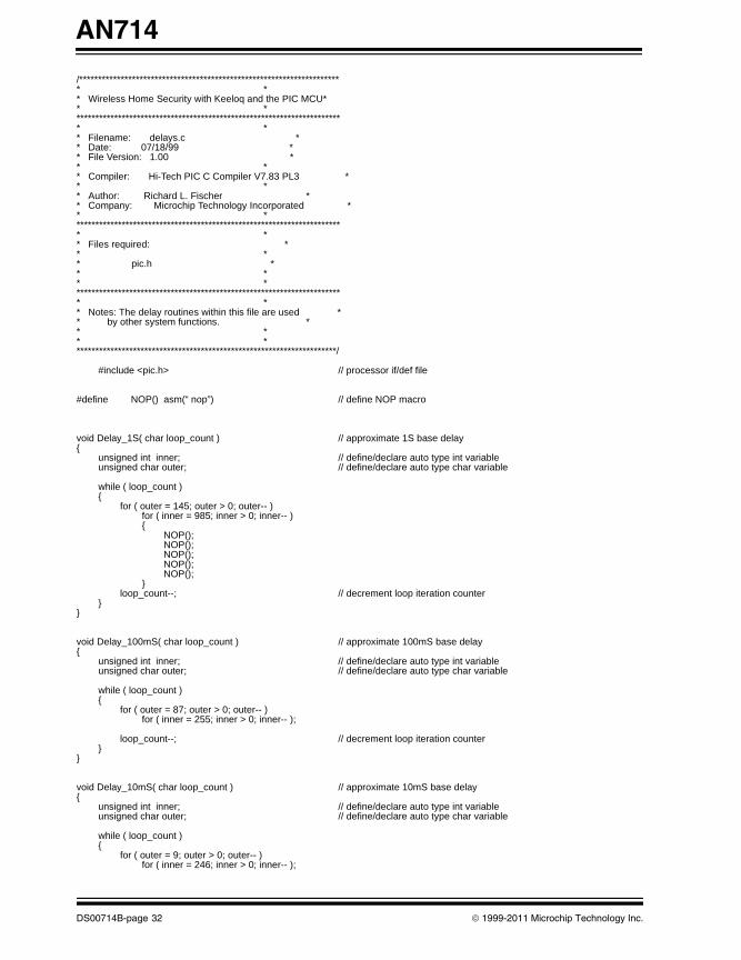
AN714
00714B.book Page 32 Friday, June 10, 2011 10:23 AM
/********************************************************************** ** Wireless Home Security with Keeloq and the PIC MCU** ************************************************************************ ** Filename: delays.c ** Date: 07/18/99 ** File Version: 1.00 ** ** Compiler: Hi-Tech PIC C Compiler V7.83 PL3 ** ** Author: Richard L. Fischer ** Company: Microchip Technology Incorporated ** ************************************************************************ ** Files required: ** ** pic.h ** ** ************************************************************************ ** Notes: The delay routines within this file are used ** by other system functions. ** ** **********************************************************************/
#include <pic.h> // processor if/def file
#define NOP() asm(“ nop”) // define NOP macro
void Delay_1S( char loop_count ) // approximate 1S base delay{
unsigned int inner; // define/declare auto type int variableunsigned char outer; // define/declare auto type char variable
while ( loop_count ){
for ( outer = 145; outer > 0; outer-- )for ( inner = 985; inner > 0; inner-- ){
NOP();NOP();NOP();NOP();NOP();
}loop_count--; // decrement loop iteration counter
}}
void Delay_100mS( char loop_count ) // approximate 100mS base delay{
unsigned int inner; // define/declare auto type int variableunsigned char outer; // define/declare auto type char variable
while ( loop_count ){
for ( outer = 87; outer > 0; outer-- )for ( inner = 255; inner > 0; inner-- );
loop_count--; // decrement loop iteration counter}
}
void Delay_10mS( char loop_count ) // approximate 10mS base delay{
unsigned int inner; // define/declare auto type int variableunsigned char outer; // define/declare auto type char variable
while ( loop_count ){
for ( outer = 9; outer > 0; outer-- )for ( inner = 246; inner > 0; inner-- );
DS00714B-page 32 © 1999-2011 Microchip Technology Inc.
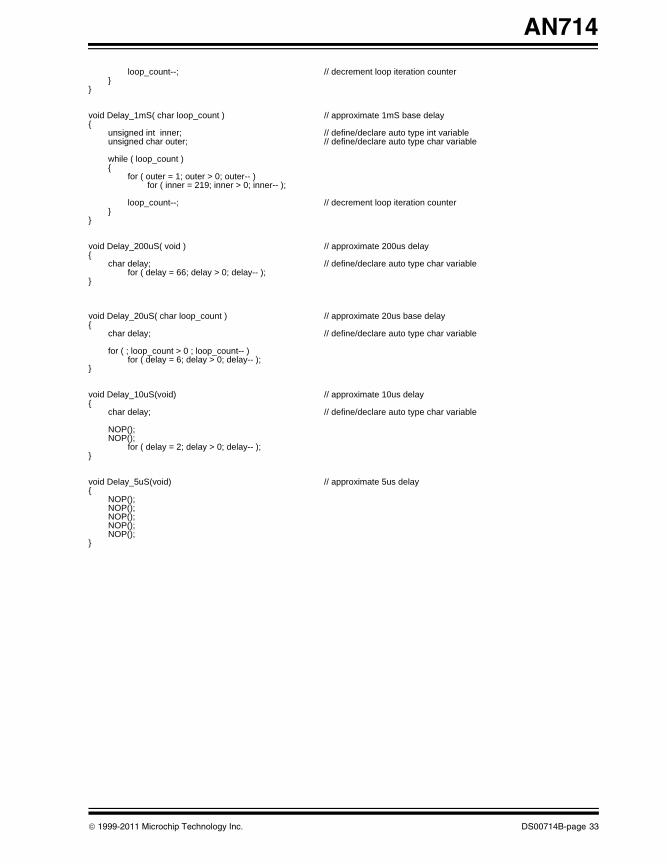
AN714
00714B.book Page 33 Friday, June 10, 2011 10:23 AM
loop_count--; // decrement loop iteration counter}
}
void Delay_1mS( char loop_count ) // approximate 1mS base delay{
unsigned int inner; // define/declare auto type int variableunsigned char outer; // define/declare auto type char variable
while ( loop_count ){
for ( outer = 1; outer > 0; outer-- )for ( inner = 219; inner > 0; inner-- );
loop_count--; // decrement loop iteration counter}
}
void Delay_200uS( void ) // approximate 200us delay{
char delay; // define/declare auto type char variablefor ( delay = 66; delay > 0; delay-- );
}
void Delay_20uS( char loop_count ) // approximate 20us base delay{
char delay; // define/declare auto type char variable
for ( ; loop_count > 0 ; loop_count-- )for ( delay = 6; delay > 0; delay-- );
}
void Delay_10uS(void) // approximate 10us delay{
char delay; // define/declare auto type char variable
NOP();NOP();
for ( delay = 2; delay > 0; delay-- );}
void Delay_5uS(void) // approximate 5us delay{
NOP();NOP();NOP();NOP();NOP();
}
© 1999-2011 Microchip Technology Inc. DS00714B-page 33
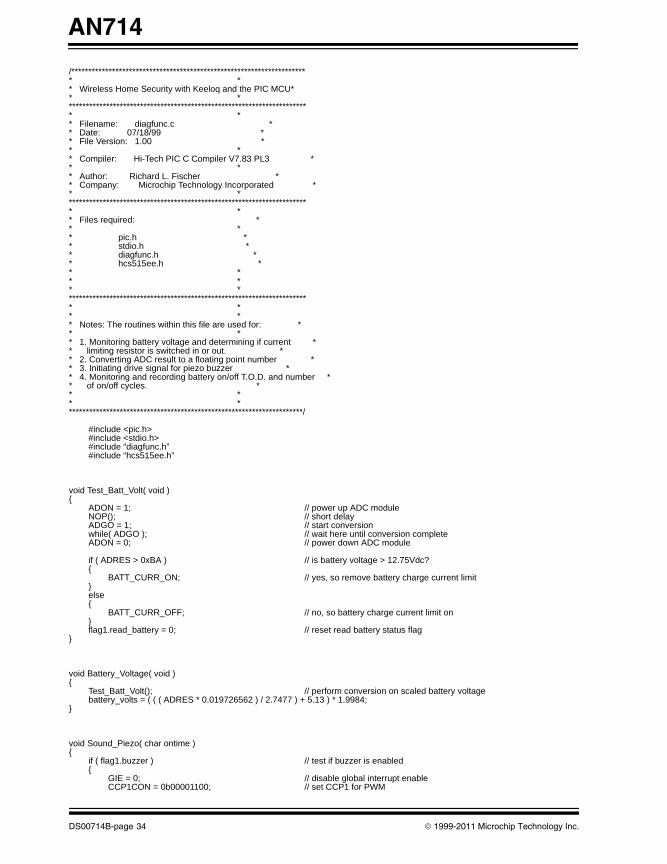
AN714
00714B.book Page 34 Friday, June 10, 2011 10:23 AM
/********************************************************************** ** Wireless Home Security with Keeloq and the PIC MCU** ************************************************************************ ** Filename: diagfunc.c ** Date: 07/18/99 ** File Version: 1.00 ** ** Compiler: Hi-Tech PIC C Compiler V7.83 PL3 ** ** Author: Richard L. Fischer ** Company: Microchip Technology Incorporated ** ************************************************************************ ** Files required: ** ** pic.h ** stdio.h ** diagfunc.h ** hcs515ee.h ** ** ** ************************************************************************ ** ** Notes: The routines within this file are used for: ** ** 1. Monitoring battery voltage and determining if current ** limiting resistor is switched in or out. ** 2. Converting ADC result to a floating point number ** 3. Initiating drive signal for piezo buzzer ** 4. Monitoring and recording battery on/off T.O.D. and number ** of on/off cycles. ** ** **********************************************************************/
#include <pic.h>#include <stdio.h>#include “diagfunc.h”#include “hcs515ee.h”
void Test_Batt_Volt( void ){
ADON = 1; // power up ADC moduleNOP(); // short delayADGO = 1; // start conversionwhile( ADGO ); // wait here until conversion completeADON = 0; // power down ADC module
if ( ADRES > 0xBA ) // is battery voltage > 12.75Vdc?{
BATT_CURR_ON; // yes, so remove battery charge current limit}else{
BATT_CURR_OFF; // no, so battery charge current limit on}flag1.read_battery = 0; // reset read battery status flag
}
void Battery_Voltage( void ){
Test_Batt_Volt(); // perform conversion on scaled battery voltagebattery_volts = ( ( ( ADRES * 0.019726562 ) / 2.7477 ) + 5.13 ) * 1.9984;
}
void Sound_Piezo( char ontime ){
if ( flag1.buzzer ) // test if buzzer is enabled{
GIE = 0; // disable global interrupt enableCCP1CON = 0b00001100; // set CCP1 for PWM
DS00714B-page 34 © 1999-2011 Microchip Technology Inc.
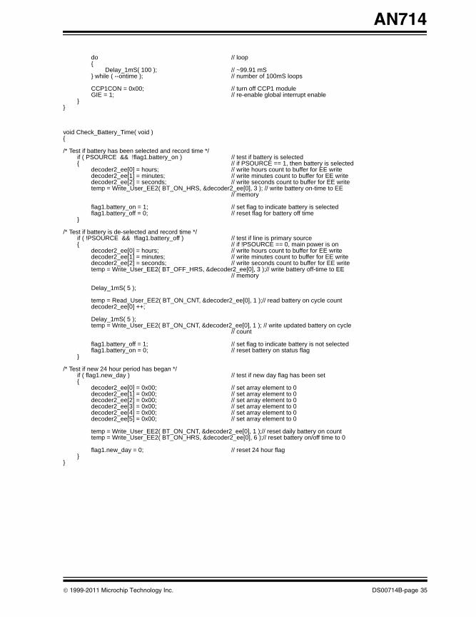
AN714
00714B.book Page 35 Friday, June 10, 2011 10:23 AM
do // loop{
Delay_1mS( 100 ); // ~99.91 mS} while ( --ontime ); // number of 100mS loops
CCP1CON = 0x00; // turn off CCP1 moduleGIE = 1; // re-enable global interrupt enable
}}
void Check_Battery_Time( void ){
/* Test if battery has been selected and record time */if ( PSOURCE && !flag1.battery_on ) // test if battery is selected{ // if PSOURCE == 1, then battery is selected
decoder2_ee[0] = hours; // write hours count to buffer for EE writedecoder2_ee[1] = minutes; // write minutes count to buffer for EE writedecoder2_ee[2] = seconds; // write seconds count to buffer for EE writetemp = Write_User_EE2( BT_ON_HRS, &decoder2_ee[0], 3 ); // write battery on-time to EE
// memory
flag1.battery_on = 1; // set flag to indicate battery is selectedflag1.battery_off = 0; // reset flag for battery off time
}
/* Test if battery is de-selected and record time */if ( !PSOURCE && !flag1.battery_off ) // test if line is primary source{ // if !PSOURCE == 0, main power is on
decoder2_ee[0] = hours; // write hours count to buffer for EE writedecoder2_ee[1] = minutes; // write minutes count to buffer for EE writedecoder2_ee[2] = seconds; // write seconds count to buffer for EE write
temp = Write_User_EE2( BT_OFF_HRS, &decoder2_ee[0], 3 );// write battery off-time to EE // memory
Delay_1mS( 5 );
temp = Read_User_EE2( BT_ON_CNT, &decoder2_ee[0], 1 );// read battery on cycle countdecoder2_ee[0] ++;
Delay_1mS( 5 );temp = Write_User_EE2( BT_ON_CNT, &decoder2_ee[0], 1 ); // write updated battery on cycle
// count
flag1.battery_off = 1; // set flag to indicate battery is not selectedflag1.battery_on = 0; // reset battery on status flag
}
/* Test if new 24 hour period has began */if ( flag1.new_day ) // test if new day flag has been set{
decoder2_ee[0] = 0x00; // set array element to 0 decoder2_ee[1] = 0x00; // set array element to 0 decoder2_ee[2] = 0x00; // set array element to 0 decoder2_ee[3] = 0x00; // set array element to 0 decoder2_ee[4] = 0x00; // set array element to 0 decoder2_ee[5] = 0x00; // set array element to 0
temp = Write_User_EE2( BT_ON_CNT, &decoder2_ee[0], 1 );// reset daily battery on counttemp = Write_User_EE2( BT_ON_HRS, &decoder2_ee[0], 6 );// reset battery on/off time to 0
flag1.new_day = 0; // reset 24 hour flag}
}
© 1999-2011 Microchip Technology Inc. DS00714B-page 35
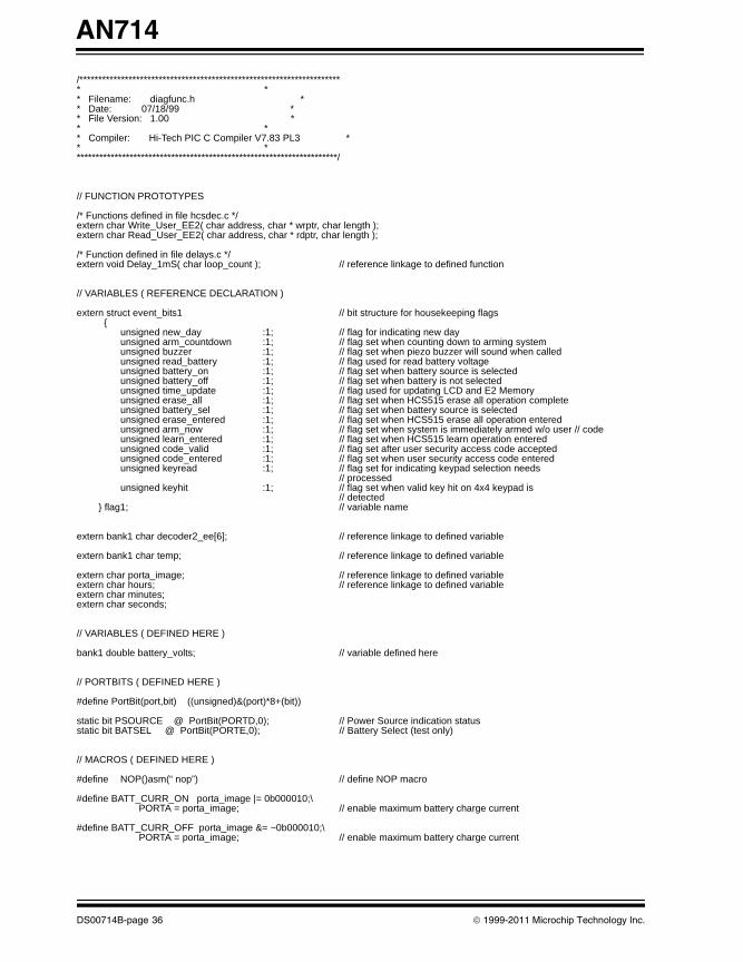
AN714
00714B.book Page 36 Friday, June 10, 2011 10:23 AM
/********************************************************************** ** Filename: diagfunc.h ** Date: 07/18/99 ** File Version: 1.00 ** ** Compiler: Hi-Tech PIC C Compiler V7.83 PL3 ** **********************************************************************/
// FUNCTION PROTOTYPES
/* Functions defined in file hcsdec.c */extern char Write_User_EE2( char address, char * wrptr, char length );extern char Read_User_EE2( char address, char * rdptr, char length );
/* Function defined in file delays.c */extern void Delay_1mS( char loop_count ); // reference linkage to defined function
// VARIABLES ( REFERENCE DECLARATION )
extern struct event_bits1 // bit structure for housekeeping flags {
unsigned new_day :1; // flag for indicating new dayunsigned arm_countdown :1; // flag set when counting down to arming system unsigned buzzer :1; // flag set when piezo buzzer will sound when called unsigned read_battery :1; // flag used for read battery voltageunsigned battery_on :1; // flag set when battery source is selectedunsigned battery_off :1; // flag set when battery is not selectedunsigned time_update :1; // flag used for updating LCD and E2 Memory unsigned erase_all :1; // flag set when HCS515 erase all operation completeunsigned battery_sel :1; // flag set when battery source is selectedunsigned erase_entered :1; // flag set when HCS515 erase all operation enteredunsigned arm_now :1; // flag set when system is immediately armed w/o user // codeunsigned learn_entered :1; // flag set when HCS515 learn operation enteredunsigned code_valid :1; // flag set after user security access code acceptedunsigned code_entered :1; // flag set when user security access code enteredunsigned keyread :1; // flag set for indicating keypad selection needs
// processedunsigned keyhit :1; // flag set when valid key hit on 4x4 keypad is
// detected} flag1; // variable name
extern bank1 char decoder2_ee[6]; // reference linkage to defined variable
extern bank1 char temp; // reference linkage to defined variable
extern char porta_image; // reference linkage to defined variableextern char hours; // reference linkage to defined variableextern char minutes;extern char seconds;
// VARIABLES ( DEFINED HERE )
bank1 double battery_volts; // variable defined here
// PORTBITS ( DEFINED HERE )
#define PortBit(port,bit) ((unsigned)&(port)*8+(bit))
static bit PSOURCE @ PortBit(PORTD,0); // Power Source indication statusstatic bit BATSEL @ PortBit(PORTE,0); // Battery Select (test only)
// MACROS ( DEFINED HERE )
#define NOP()asm(“ nop”) // define NOP macro
#define BATT_CURR_ON porta_image |= 0b000010;\ PORTA = porta_image; // enable maximum battery charge current
#define BATT_CURR_OFF porta_image &= ~0b000010;\ PORTA = porta_image; // enable maximum battery charge current
DS00714B-page 36 © 1999-2011 Microchip Technology Inc.
AN714
00714B.book Page 37 Friday, June 10, 2011 10:23 AM
/********************************************************************** ** Wireless Home Security with Keeloq and the PIC MCU** ************************************************************************ ** Filename: hcsdec.c ** Date: 07/18/99 ** File Version: 1.00 ** ** Compiler: Hi-Tech PIC C Compiler V7.83 PL3 ** ** Author: Richard L. Fischer ** Company: Microchip Technology Incorporated ** ************************************************************************ ** Files required: ** ** pic.h ** stdio.h ** hcsdec.h ** ** ** ************************************************************************ ** ** Notes: The routines within this file are required for ** communicating with the system HCS515 decoders. ** ** ** **********************************************************************/
#include <pic.h>#include <stdio.h>#include “hcsdec.h”
void Read_Trans( char length ){
TRISDATA2 = 1; // ensure pin direction is inputlrn_ptr = decoder2 // initialize pointer
Delay_20uS( 3 ); // intervals of 20uS delay ( 61uS total )HCSCLK2 = 1; // assert clock - provide ack to HCS515
Delay_20uS( 2 ); // ~42uS ( Tclh )HCSCLK2 = 0; // negate clockDelay_20uS( 2 ); // ~42uS ( Tcll )
while ( length ) // stay while length != 0{
command.bit_counter = 8; // initialize bit counterdo{
HCSCLK2 = 1; // set clock high (total high time - 26uS)NOP(); // add in .5uS delayDelay_20uS( 1 ); // ~24uS delayHCSCLK2 = 0; // set clock low (sample data after falling edge )
// (total low time - 31.5uS)temp_buffer >> = 1;> // rotate buffer contents towards LSBif ( HCSDATA2 ) // test if data line is logic 1{
temp_buffer |= 0x80; // set bit 7 to logic 1}Delay_20uS( 1 ); // ~24uS delay
} while ( --command.bit_counter ); // decrement counter and test if complete
*lrn_ptr++ = temp_buffer; // save off read byte and update pointerlength --; // decrement loop length counter
} }
char Read_Learn( char length ){
TRISDATA2 = 1; // ensure pin direction is inputHCSCLK2 = 0; // ensure clock line is low
© 1999-2011 Microchip Technology Inc. DS00714B-page 37
AN714
00714B.book Page 38 Friday, June 10, 2011 10:23 AM
lrn_ptr = decoder2; // initialize pointercommand.treq_timeout = 0x0000; // initialize union variable (integer element)
do // loop until HCS515 responds{ // or until ~35 seconds expires
Delay_1mS( 2 ); // intervals of 2mS delayDelay_20uS( 20 ); // plus command.treq_timeout++; // increment response wait timer
if ( HCSDATA2 == 1 ) // has HCS515 responded ?{
command.treq_timeout = TREQ +1; // if so then set timeout expiration}
} while ( command.treq_timeout <= TREQ );
Home_Clr(); // clear lcd and set to line1 / position 1if ( HCSDATA2 == 0 ) // is data line still low?{ // transmission has not been detected 35 sec.
return ( TREQ_ERR ); // return with error code}
// At this point the first of two learn transmissions has been receivedDelay_100mS( 1 ); // delay of 100mS delay
if ( HCSDATA2 != 0 ) // data line should be lo at this pointw{
return ( TREQ_ERR ); // else, return with error code}
command.treq_timeout = 0x0000; // initialize union variable (integer element)
printf(“1st trans. rcv’d” ); // format message for LCD Line_2(); // position lcd cursor on line2 / position 1printf(“30 seconds left “ ); // format message for LCD
// wait here for second transmissiondo // loop until HCS515 responds{ // or until ~30sec expires
Delay_1mS( 1 ); // intervals of 1.3mS delayDelay_20uS( 20 ); // plus morecommand.treq_timeout++; // increment response wait timer
if ( HCSDATA2 == 1 ) // has HCS515 responded ?{
command.treq_timeout = TREQ +1; // if so then set timeout expiration}
} while ( command.treq_timeout <= TREQ );
Home_Clr(); // clear lcd and set to line1 / position 1if ( HCSDATA2 == 0 ) // is data line still low?{
return ( TREQ_ERR ); // return with error code}
// At this point the second and final learn transmission has been received by the HCS515 command.tack_timeout = 0x00; // initialize union variable (char element)
Delay_20uS( 4 ); // Tcla wait period (spec - 50ouS min) HCSCLK2 = 1; // assert clock, send acknowledge to HCS515
do // loop until HCS515 responds{ // or until wait time expires
Delay_5uS();command.tack_timeout++; // increment response wait timer
if ( HCSDATA2 == 0 ) // has HCS515 responded ?{
command.tack_timeout = TACK +1; // if so then set timeout expiration}
} while ( command.tack_timeout <= TACK );
if ( HCSDATA2 == 1 ) // is data line still high?{
return ( TACK_ERR ); // return with error code}
Delay_20uS( 2 ); // ~42uS ( Tclh )HCSCLK2 = 0; // negate clockDelay_20uS( 2 ); // ~42uS ( Tcll )TRISDATA2 = 1; // set data pin direction
// Read x number of bytes from the second transmission ( up to 10 )while ( length ){
DS00714B-page 38 © 1999-2011 Microchip Technology Inc.
AN714
00714B.book Page 39 Friday, June 10, 2011 10:23 AM
command.bit_counter = 8; // initialize bit counterdo{
HCSCLK2 = 1; // set clock highNOP(); // add in .5uS delayDelay_20uS( 1 ); // ~22uS delayHCSCLK2 = 0; // set clock low ( data sampled on falling edge )
temp_buffer >> = 1; // rotate towards LSB positionif ( HCSDATA2 ) // test if carry bit set{
temp_buffer |= 0x80; // set bit 7 to logic 1}Delay_20uS( 1 ); // ~22uS delay
} while ( --command.bit_counter ); // decrement counter and test if complete
*lrn_ptr++ = temp_buffer; // save off learn status message and update pointerlength --; // decrement byte counter
}
return ( NO_ERROR ); // return with no read error}
char Learn( void ){
flag1.learn_entered = 0; // reset learn entered flag
temp = Command_Mode( ACTIVE_LRN, DUMMY, DUMMY ); // initiate command modeif ( temp != 0 ){
return ( temp ); // return with error code }
// At this point Command Mode for Learn has been sent to HCS515, wait for acknowledge// HCS515 should respond within 20uS (max) after clock line is asserted
TRISDATA2 = 1; // ensure data direction pin state is inputDelay_20uS( 2 ); // wait for ~ 40uS (Tlrn-20uS(min) Tlrn )HCSCLK2 = 1; // set clock high, begin TACK period
command.tack_timeout = 0x00; // initialize variabledo // loop until HCS515 responds with{ // data line high or until time expires
// loop time ~8uS (total: 5*8us= 40uS)command.tack_timeout++; // increment timeout counter
if ( HCSDATA2 == 1 ) // has HCS515 responded and entered learn mode ?{
command.tack_timeout = TACK_LRN +1;// if so then set timeout expiration}
} while ( ( !HCSDATA2 ) && ( command.tack_timeout <= TACK_LRN ) );
if ( !HCSDATA2 ) // is DATA line still low after TACK{
return ( TACK_LRN_ERR ); // return with error code}
Delay_20uS( 1 ); // ~22uS delay (Tresp spec 20-1000uS)HCSCLK2 = 0; // set clock lowDelay_20uS( 1 ); // ~22uS delay (TACK2 spec 10uS max)
flag1.learn_entered = 1; // set flag learn entered modereturn ( NO_ERROR ); // return with no error condition
}
char Erase_All( void ){
flag1.erase_all = 0; // reset flag for erase all status
temp = Command_Mode( ERASE_ALL, SUBCOM0, DUMMY ); // initiate command modeif ( temp != 0 ){
return ( temp ); // return with error code }
TRISDATA2 = 1; // ensure data direction pin state is inputDelay_20uS( 2 ); // wait for ~ 42uS( Tera time ) HCSCLK2 = 1; // set clock high, begin TACK period
© 1999-2011 Microchip Technology Inc. DS00714B-page 39
AN714
00714B.book Page 40 Friday, June 10, 2011 10:23 AM
command.tack_timeout = 0x00; // initialize variabledo // loop until HCS515 responds with{ // driving data line high or until time expires
Delay_20uS( 46 ); // wait ~900uS per loop (spec - 210mS max)command.tack_timeout++; // increment timeout counter
if ( HCSDATA2 == 1 ) // has HCS515 finished erasing xmtrs ?{
command.tack_timeout = TACK_ERASE +1; // if so then set timeout expiration}
} while ( ( !HCSDATA2 ) && ( command.tack_timeout <= TACK_ERASE ) );
if ( !HCSDATA2 ) // is DATA line still low after TACK (max){
return ( TACK_ERASE_ERR ); // return with error code}
Delay_20uS( 1 ); // ~22uS delay (Tresp)HCSCLK2 = 0; // set clock lowDelay_20uS( 1 ); // ~22uS delay (TACK2 wait)
flag1.erase_all = 1; // set flag to indicate all xmtrs have been erasedreturn ( NO_ERROR ); // return with no error condition
}
char Read_User_EE2( char address, char * rdptr, char length ){ temp = Command_Mode( READ, address, DUMMY ); // initiate command mode
if ( temp != 0 ){
return ( temp ); // return with error code }
Delay_20uS( 50 ); // Trd time period (1000 - 2000uS)TRISDATA2 = 1; // ensure data direction pin state is input
while ( length ) // test byte read counter is zero{
command.bit_counter = 8; // initialize bit counterdo{
HCSCLK2 = 1; // set clock highNOP(); // add in .5uS delayDelay_20uS( 1 ); // ~22uS delayHCSCLK2 = 0; // set clock low ( data sampled on falling edge )
temp_buffer >> = 1; // rotate towards LSB positionif ( HCSDATA2 ) // test if carry bit set{
temp_buffer |= 0x80; // set bit 7 to logic 1}Delay_20uS( 1 ); // ~22uS delay
} while ( --command.bit_counter ); // decrement counter and test if complete
*rdptr++ = temp_buffer; // save off read byte and update pointer
Delay_20uS( 50 ); // Trd time period (1000 - 2000uS)length --; // decrement read counter}
HCSDATA2 = 0; // ensure data line is set lowTRISDATA2 = 1; // ensure direction of pin is inputreturn ( NO_ERROR ); // return with no error
}
char Write_User_EE2( char address, char * wrptr, char length ){
temp = Command_Mode( WRITE, address, WRITE ); // initiate command modeif ( temp != 0 ){
return ( temp ); // return with error code}
while ( length ) // test for end of string (null character){
TRISDATA2 = 0; // ensure data direction pin state is outputcommand.bit_counter = 8; // initialize bit countertemp_buffer = *wrptr; // assign data to temp_buffer
DS00714B-page 40 © 1999-2011 Microchip Technology Inc.
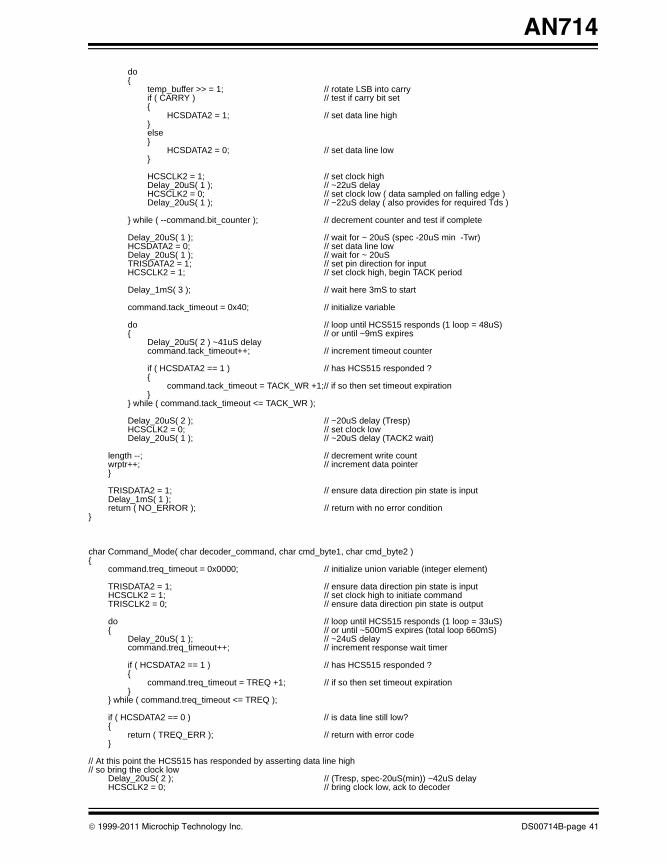
AN714
00714B.book Page 41 Friday, June 10, 2011 10:23 AM
do{
temp_buffer >> = 1; // rotate LSB into carryif ( CARRY ) // test if carry bit set{
HCSDATA2 = 1; // set data line high}else }
HCSDATA2 = 0; // set data line low}
HCSCLK2 = 1; // set clock highDelay_20uS( 1 ); // ~22uS delayHCSCLK2 = 0; // set clock low ( data sampled on falling edge )Delay_20uS( 1 ); // ~22uS delay ( also provides for required Tds )
} while ( --command.bit_counter ); // decrement counter and test if complete
Delay_20uS( 1 ); // wait for ~ 20uS (spec -20uS min -Twr)HCSDATA2 = 0; // set data line lowDelay_20uS( 1 ); // wait for ~ 20uS TRISDATA2 = 1; // set pin direction for inputHCSCLK2 = 1; // set clock high, begin TACK period
Delay_1mS( 3 ); // wait here 3mS to start
command.tack_timeout = 0x40; // initialize variable
do // loop until HCS515 responds (1 loop = 48uS){ // or until ~9mS expires
Delay_20uS( 2 ) ~41uS delaycommand.tack_timeout++; // increment timeout counter
if ( HCSDATA2 == 1 ) // has HCS515 responded ?{
command.tack_timeout = TACK_WR +1;// if so then set timeout expiration}
} while ( command.tack_timeout <= TACK_WR );
Delay_20uS( 2 ); // ~20uS delay (Tresp)HCSCLK2 = 0; // set clock lowDelay_20uS( 1 ); // ~20uS delay (TACK2 wait)
length --; // decrement write count wrptr++; // increment data pointer}
TRISDATA2 = 1; // ensure data direction pin state is inputDelay_1mS( 1 );return ( NO_ERROR ); // return with no error condition
}
char Command_Mode( char decoder_command, char cmd_byte1, char cmd_byte2 ){
command.treq_timeout = 0x0000; // initialize union variable (integer element)
TRISDATA2 = 1; // ensure data direction pin state is inputHCSCLK2 = 1; // set clock high to initiate commandTRISCLK2 = 0; // ensure data direction pin state is output
do // loop until HCS515 responds (1 loop = 33uS){ // or until ~500mS expires (total loop 660mS)
Delay_20uS( 1 ); // ~24uS delaycommand.treq_timeout++; // increment response wait timer
if ( HCSDATA2 == 1 ) // has HCS515 responded ?{
command.treq_timeout = TREQ +1; // if so then set timeout expiration}
} while ( command.treq_timeout <= TREQ );
if ( HCSDATA2 == 0 ) // is data line still low?{
return ( TREQ_ERR ); // return with error code}
// At this point the HCS515 has responded by asserting data line high// so bring the clock low
Delay_20uS( 2 ); // (Tresp, spec-20uS(min)) ~42uS delayHCSCLK2 = 0; // bring clock low, ack to decoder
© 1999-2011 Microchip Technology Inc. DS00714B-page 41
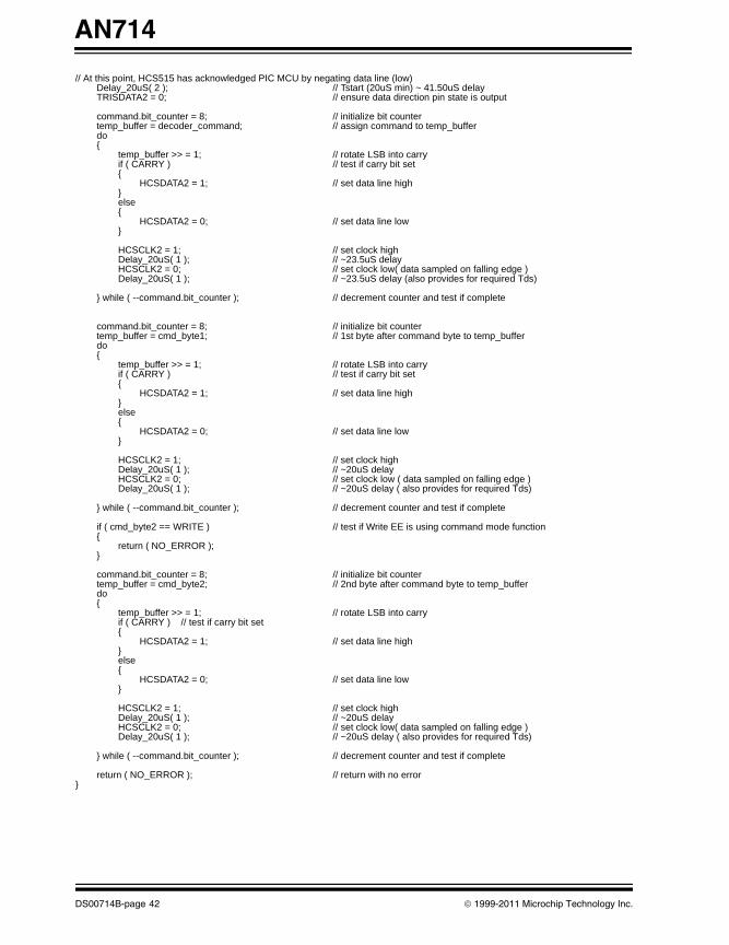
AN714
00714B.book Page 42 Friday, June 10, 2011 10:23 AM
// At this point, HCS515 has acknowledged PIC MCU by negating data line (low)Delay_20uS( 2 ); // Tstart (20uS min) ~ 41.50uS delayTRISDATA2 = 0; // ensure data direction pin state is output
command.bit_counter = 8; // initialize bit countertemp_buffer = decoder_command; // assign command to temp_bufferdo{
temp_buffer >> = 1; // rotate LSB into carryif ( CARRY ) // test if carry bit set{
HCSDATA2 = 1; // set data line high }
else {
HCSDATA2 = 0; // set data line low }
HCSCLK2 = 1; // set clock highDelay_20uS( 1 ); // ~23.5uS delay HCSCLK2 = 0; // set clock low( data sampled on falling edge )Delay_20uS( 1 ); // ~23.5uS delay (also provides for required Tds)
} while ( --command.bit_counter ); // decrement counter and test if complete
command.bit_counter = 8; // initialize bit countertemp_buffer = cmd_byte1; // 1st byte after command byte to temp_bufferdo{
temp_buffer >> = 1; // rotate LSB into carryif ( CARRY ) // test if carry bit set{
HCSDATA2 = 1; // set data line high}else {
HCSDATA2 = 0; // set data line low }
HCSCLK2 = 1; // set clock highDelay_20uS( 1 ); // ~20uS delayHCSCLK2 = 0; // set clock low ( data sampled on falling edge )Delay_20uS( 1 ); // ~20uS delay ( also provides for required Tds)
} while ( --command.bit_counter ); // decrement counter and test if complete
if ( cmd_byte2 == WRITE ) // test if Write EE is using command mode function{
return ( NO_ERROR );}
command.bit_counter = 8; // initialize bit countertemp_buffer = cmd_byte2; // 2nd byte after command byte to temp_bufferdo{
temp_buffer >> = 1; // rotate LSB into carryif ( CARRY ) // test if carry bit set{
HCSDATA2 = 1; // set data line high}else {
HCSDATA2 = 0; // set data line low }
HCSCLK2 = 1; // set clock highDelay_20uS( 1 ); // ~20uS delay HCSCLK2 = 0; // set clock low( data sampled on falling edge )Delay_20uS( 1 ); // ~20uS delay ( also provides for required Tds)
} while ( --command.bit_counter ); // decrement counter and test if complete
return ( NO_ERROR ); // return with no error}
DS00714B-page 42 © 1999-2011 Microchip Technology Inc.
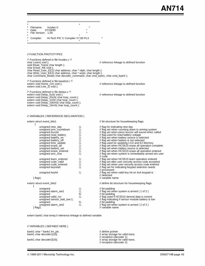
AN714
00714B.book Page 43 Friday, June 10, 2011 10:23 AM
/********************************************************************** ** Filename: hcsdec.h ** Date: 07/18/99 ** File Version: 1.00 ** ** Compiler: Hi-Tech PIC C Compiler V7.83 PL3 ** **********************************************************************/
// FUNCTION PROTOTYPES
/* Functions defined in file hcsdec.c */char Learn( void ); // reference linkage to defined functionvoid Read_Trans( char length );char Erase_All( void );char Read_User_EE2( char address, char * rdptr, char length );char Write_User_EE2( char address, char * wrptr, char length );char Command_Mode( char decoder_command, char cmd_byte1, char cmd_byte2 );
/* Functions defined in file baselcd.c */ extern void Home_Clr( void ); // reference linkage to defined functionextern void Line_2( void );
/* Functions defined in file delays.c */extern void Delay_5uS( void ); // reference linkage to defined functionextern void Delay_20uS( char loop_count );extern void Delay_1mS( char loop_count );extern void Delay_100mS( char loop_count );extern void Delay_10mS( char loop_count );
// VARIABLES ( REFERENCE DECLARATION )
extern struct event_bits1 // bit structure for housekeeping flags {
unsigned new_day :1; // flag for indicating new dayunsigned arm_countdown :1; // flag set when counting down to arming system unsigned buzzer :1; // flag set when piezo buzzer will sound when called unsigned read_battery :1; // flag used for read battery voltageunsigned battery_on :1; // flag set when battery source is selectedunsigned battery_off :1; // flag set when battery is not selectedunsigned time_update :1; // flag used for updating LCD and E2 Memory unsigned erase_all :1; // flag set when HCS515 erase all operation completeunsigned battery_sel :1; // flag set when battery source is selectedunsigned erase_entered :1; // flag set when HCS515 erase all operation enteredunsigned arm_now :1; // flag set when system is immediately armed w/o user
// codeunsigned learn_entered :1; // flag set when HCS515 learn operation enteredunsigned code_valid :1; // flag set after user security access code acceptedunsigned code_entered :1; // flag set when user security access code enteredunsigned keyread :1; // flag set for indicating keypad selection needs
// processedunsigned keyhit :1; // flag set when valid key hit on 4x4 keypad is
// detected} flag1; // variable name
extern struct event_bits2 // define bit structure for housekeeping flags{
unsigned :1; // bit paddingunsigned alarm_set1 :1; // flag set when system is armed ( 1 of 2 )unsigned :6; // bit padding unsigned valid_rcv :1; // flag used if HCS515 demod data is correctunsigned sensor_batt_low:1; // flag indicating if sensor module battery is lowunsigned :5; // bit paddingunsigned alarm_set2 :1; // flag set when system is armed ( 2 of 2 )
} flag2; // variable name
extern bank1 char temp;// reference linkage to defined variable
// VARIABLES ( DEFINED HERE )
bank1 char * bank1 lrn_ptr; // define pointerbank1 char decoder1[10]; // array storage for valid trans.
// reception (decoder 1)bank1 char decoder2[10]; // array storage for valid trans.
// reception (decoder 2)
© 1999-2011 Microchip Technology Inc. DS00714B-page 43
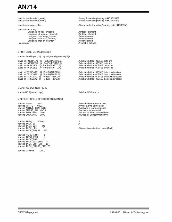
AN714
00714B.book Page 44 Friday, June 10, 2011 10:23 AM
bank1 char decoder1_ee[6]; // array for reading/writing to HCS515 EEbank1 char decoder2_ee[6]; // array for reading/writing to HCS515 EE
bank1 char temp_buffer; // temp buffer for writing/reading data ( HCS515 )
bank1 union notify {unsigned int treq_timeout; // integer elementunsigned int tack_wr_timeout; // integer elementunsigned char tresp_timeout; // char elementunsigned char tack_timeout; // char elementunsigned char bit_counter; // char element
} command; // variable defined
// PORTBITS ( DEFINED HERE )
#define PortBit(port,bit) ((unsigned)&(port)*8+(bit))
static bit HCSDATA1 @ PortBit(PORTC,6); // declare bit for HCS515 data linestatic bit HCSDATA2 @ PortBit(PORTC,5); // declare bit for HCS515 data linestatic bit HCSCLK1 @ PortBit(PORTC,7); // declare bit for HCS515 clock linestatic bit HCSCLK2 @ PortBit(PORTC,4); // declare bit for HCS515 clock line
static bit TRISDATA1 @ PortBit(TRISC,6); // declare bit for HCS515 data pin directionstatic bit TRISDATA2 @ PortBit(TRISC,5); // declare bit for HCS515 data pin directionstatic bit TRISCLK1 @ PortBit(TRISC,7); // declare bit for HCS515 clock pin directionstatic bit TRISCLK2 @ PortBit(TRISC,4); // declare bit for HCS515 clock pin direction
// MACROS DEFINED HERE
#defineNOP()asm(“ nop”) // define NOP macro
// DEFINE HCS515 DECODER COMMANDS
#define READ 0xF0 // Read a byte from the user#define WRITE 0xE1 // Write a byte to the user#define ACTIVE_LRN 0xD2 // Activate a learn sequence #define ERASE_ALL 0xC3 // Activate an erase all#define SUBCOM0 0x00 // Erase all Subcommand byte#define SUBCOM1 0x01 // Erase all Subcommand byte
#define TREQ 20000 //#define TACK 50 // #define TACK_WR 240#define TACK_LRN 5 // timeout constant for Learn (Tack)#define TACK_ERASE 250
#define NO_ERROR 0#define TREQ_ERR 1#define TACK_ERR 2#define TACK_WR_ERR 4#define TACK_LRN_ERR 10#define TACK_ERASE_ERR 20
#define DUMMY 0x81
DS00714B-page 44 © 1999-2011 Microchip Technology Inc.
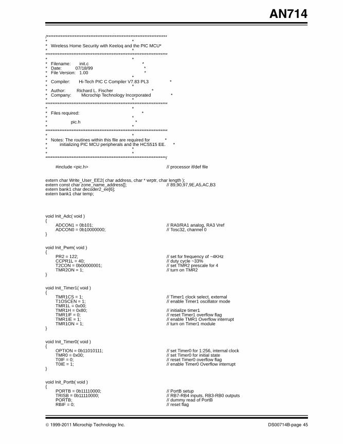
AN714
00714B.book Page 45 Friday, June 10, 2011 10:23 AM
/********************************************************************** ** Wireless Home Security with Keeloq and the PIC MCU** ************************************************************************ ** Filename: init.c ** Date: 07/18/99 ** File Version: 1.00 ** ** Compiler: Hi-Tech PIC C Compiler V7.83 PL3 ** ** Author: Richard L. Fischer ** Company: Microchip Technology Incorporated ** ************************************************************************ ** Files required: ** ** pic.h ** ************************************************************************ ** Notes: The routines within this file are required for ** initializing PIC MCU peripherals and the HCS515 EE. ** ** **********************************************************************/
#include <pic.h> // processor if/def file
extern char Write_User_EE2( char address, char * wrptr, char length );extern const char zone_name_address[]; // 89,90,97,9E,A5,AC,B3extern bank1 char decoder2_ee[6];extern bank1 char temp;
void Init_Adc( void ){
ADCON1 = 0b101; // RA0/RA1 analog, RA3 VrefADCON0 = 0b10000000; // Tosc32, channel 0
}
void Init_Pwm( void ){
PR2 = 122; // set for frequency of ~4KHzCCPR1L = 40; // duty cycle ~33%T2CON = 0b00000001; // set TMR2 prescale for 4TMR2ON = 1; // turn on TMR2
}
void Init_Timer1( void ){
TMR1CS = 1; // Timer1 clock select, externalT1OSCEN = 1; // enable Timer1 oscillator modeTMR1L = 0x00;TMR1H = 0x80; // initialize timer1 TMR1IF = 0; // reset Timer1 overflow flagTMR1IE = 1; // enable TMR1 Overflow interruptTMR1ON = 1; // turn on Timer1 module
}
void Init_Timer0( void ){
OPTION = 0b11010111; // set Timer0 for 1:256, internal clockTMR0 = 0x00; // set Timer0 for initial stateT0IF = 0; // reset Timer0 overflow flagT0IE = 1; // enable Timer0 Overflow interrupt
}
void Init_Portb( void ){
PORTB = 0b11110000; // PortB setupTRISB = 0b11110000; // RB7-RB4 inputs, RB3-RB0 outputsPORTB; // dummy read of PortBRBIF = 0; // reset flag
© 1999-2011 Microchip Technology Inc. DS00714B-page 45
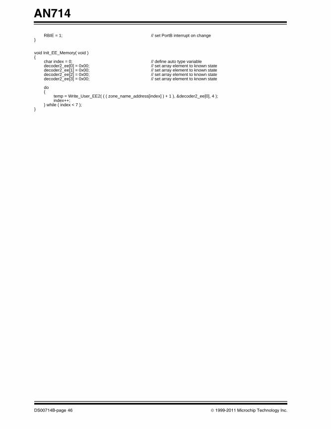
AN714
00714B.book Page 46 Friday, June 10, 2011 10:23 AM
RBIE = 1; // set PortB interrupt on change }
void Init_EE_Memory( void ){
char index = 0; // define auto type variabledecoder2_ee[0] = 0x00; // set array element to known state decoder2_ee[1] = 0x00; // set array element to known state decoder2_ee[2] = 0x00; // set array element to known state decoder2_ee[3] = 0x00; // set array element to known state
do{
temp = Write_User_EE2( ( ( zone_name_address[index] ) + 1 ), &decoder2_ee[0], 4 );index++;
} while ( index < 7 );}
DS00714B-page 46 © 1999-2011 Microchip Technology Inc.
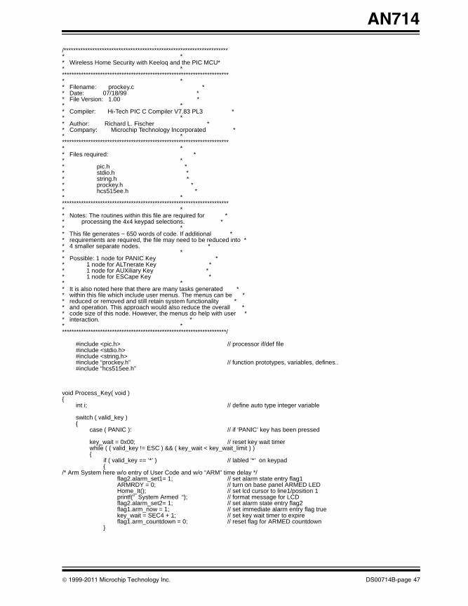
AN714
00714B.book Page 47 Friday, June 10, 2011 10:23 AM
/********************************************************************** ** Wireless Home Security with Keeloq and the PIC MCU** ************************************************************************ ** Filename: prockey.c ** Date: 07/18/99 ** File Version: 1.00 ** ** Compiler: Hi-Tech PIC C Compiler V7.83 PL3 ** ** Author: Richard L. Fischer ** Company: Microchip Technology Incorporated ** ************************************************************************ ** Files required: ** ** pic.h ** stdio.h ** string.h ** prockey.h ** hcs515ee.h ** ************************************************************************ ** Notes: The routines within this file are required for ** processing the 4x4 keypad selections. ** ** This file generates ~ 650 words of code. If additional ** requirements are required, the file may need to be reduced into ** 4 smaller separate nodes. ** ** Possible: 1 node for PANIC Key ** 1 node for ALTnerate Key ** 1 node for AUXiliary Key ** 1 node for ESCape Key ** ** It is also noted here that there are many tasks generated ** within this file which include user menus. The menus can be ** reduced or removed and still retain system functionality ** and operation. This approach would also reduce the overall ** code size of this node. However, the menus do help with user ** interaction. ** **********************************************************************/
#include <pic.h> // processor if/def file#include <stdio.h>#include <string.h>#include “prockey.h” // function prototypes, variables, defines..#include “hcs515ee.h”
void Process_Key( void ){
int i; // define auto type integer variable
switch ( valid_key ){
case ( PANIC ): // if ‘PANIC’ key has been pressed
key_wait = 0x00; // reset key wait timerwhile ( ( valid_key != ESC ) && ( key_wait < key_wait_limit ) ){
if ( valid_key == ‘*’ ) // labled ‘*’ on keypad {
/* Arm System here w/o entry of User Code and w/o “ARM” time delay */flag2.alarm_set1= 1; // set alarm state entry flag1ARMRDY = 0; // turn on base panel ARMED LEDHome_It(); // set lcd cursor to line1/position 1printf(“ System Armed “); // format message for LCDflag2.alarm_set2= 1; // set alarm state entry flag2flag1.arm_now = 1; // set immediate alarm entry flag truekey_wait = SEC4 + 1; // set key wait timer to expireflag1.arm_countdown = 0; // reset flag for ARMED countdown
}
© 1999-2011 Microchip Technology Inc. DS00714B-page 47
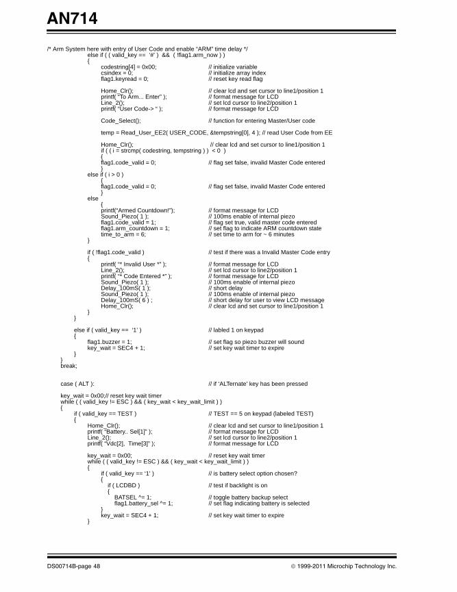
AN714
00714B.book Page 48 Friday, June 10, 2011 10:23 AM
/* Arm System here with entry of User Code and enable “ARM” time delay */else if ( ( valid_key == ‘#’ ) && ( !flag1.arm_now ) ) {
codestring[4] = 0x00; // initialize variablecsindex = 0; // initialize array indexflag1.keyread = 0; // reset key read flag
Home_Clr(); // clear lcd and set cursor to line1/position 1printf( “To Arm... Enter” ); // format message for LCDLine_2(); // set lcd cursor to line2/position 1printf( “User Code-> “ ); // format message for LCD
Code_Select(); // function for entering Master/User code
temp = Read_User_EE2( USER_CODE, &tempstring[0], 4 ); // read User Code from EE
Home_Clr(); // clear lcd and set cursor to line1/position 1if ( ( i = strcmp( codestring, tempstring ) ) < 0 ){flag1.code_valid = 0; // flag set false, invalid Master Code entered}
else if ( i > 0 ){flag1.code_valid = 0; // flag set false, invalid Master Code entered}
else{printf(“Armed Countdown!”); // format message for LCDSound_Piezo( 1 ); // 100ms enable of internal piezoflag1.code_valid = 1; // flag set true, valid master code enteredflag1.arm_countdown = 1; // set flag to indicate ARM countdown statetime_to_arm = 6; // set time to arm for ~ 6 minutes
}
if ( !flag1.code_valid ) // test if there was a Invalid Master Code entry{
printf( “* Invalid User *” ); // format message for LCDLine_2(); // set lcd cursor to line2/position 1printf( “* Code Entered *” ); // format message for LCDSound_Piezo( 1 ); // 100ms enable of internal piezoDelay_100mS( 1 ); // short delaySound_Piezo( 1 ); // 100ms enable of internal piezoDelay_100mS( 6 ) ; // short delay for user to view LCD messageHome_Clr(); // clear lcd and set cursor to line1/position 1
}}
else if ( valid_key == ‘1’ ) // labled 1 on keypad{
flag1.buzzer = 1; // set flag so piezo buzzer will soundkey_wait = SEC4 + 1; // set key wait timer to expire
}}break;
case ( ALT ): // if ‘ALTernate’ key has been pressed
key_wait = 0x00;// reset key wait timerwhile ( ( valid_key != ESC ) && ( key_wait < key_wait_limit ) ){
if ( valid_key == TEST ) // TEST == 5 on keypad (labeled TEST){
Home_Clr(); // clear lcd and set cursor to line1/position 1printf( “Battery.. Sel[1]” ); // format message for LCDLine_2(); // set lcd cursor to line2/position 1printf( “Vdc[2], Time[3]” ); // format message for LCD
key_wait = 0x00; // reset key wait timerwhile ( ( valid_key != ESC ) && ( key_wait < key_wait_limit ) ){
if ( valid_key == ‘1’ ) // is battery select option chosen? {
if ( LCDBD ) // test if backlight is on{
BATSEL ^= 1; // toggle battery backup selectflag1.battery_sel ^= 1; // set flag indicating battery is selected
}key_wait = SEC4 + 1; // set key wait timer to expire
}
DS00714B-page 48 © 1999-2011 Microchip Technology Inc.
AN714
00714B.book Page 49 Friday, June 10, 2011 10:23 AM
else if ( valid_key == ‘2’ ) // is battery voltage option chosen?{
while ( valid_key != ESC ) // stay in loop until ESCape key is pressed{
Home_It(); // set lcd cursor to line1/position 1if ( !PSOURCE ) // test if primary power is on{
Battery_Voltage(); // perform conversion on ADC channel 0printf(“Battery Voltage:” ); // format message for LCD Line_2(); // set lcd cursor to line2/position 1printf(“ %.3f Vdc “, battery_volts ); // format message for LCD
}else // primary is not on{
printf(“ Battery Source “ ); // format message for LCD Line_2(); // set lcd cursor to line2/position 1printf(“ is selected “ ); // format message for LCD
}Delay_100mS( 1 ); // ~100 mS delay
}}
else if ( valid_key == ‘3’ ) // display recorded battery on time{
Home_Clr(); // clear lcd and set cursor to line1/position 1temp = Read_User_EE2( BT_ON_HRS, &decoder2_ee[0], 6 ); // read recorded time of
// battery onprintf( “on: -> %02u:%02u:%02u “ , decoder2_ee[0],decoder2_ee[1],decoder2_ee[2] );Line_2(); // set lcd cursor to line2/position 1printf( “off:--> %02u:%02u:%02u” , decoder2_ee[3],decoder2_ee[4],decoder2_ee[5] );valid_key = 0x20; // reset keywhile ( valid_key != ESC ); // stay in loop until ESCape key is pressedHome_Clr(); // clear lcd and set cursor to line1/position 1printf( “Battery daily “ ); // format message for LCDLine_2(); // set lcd cursor to line2/position 1temp = Read_User_EE2( BT_ON_CNT, &decoder2_ee[0], 1 ); // read daily battery cycle
// count
printf( “cycle count= %02u” , decoder2_ee[0] ); // format message for LCDvalid_key = 0x20; // reset key while ( valid_key != ESC ); // stay in loop until ESCape key is pressed
}}
}
else if ( valid_key == ALARM_STATUS ) // ALARM_STATUS == 7 on keypad (labeled INSTANT){
Home_It(); // set lcd cursor to line1/position 1temp = Read_User_EE2( ALRM_HRS, &decoder2_ee[0], 4 ); // read alarm status and time info
if ( decoder2_ee[3] == CLEAR ){
printf( “ No Zone Fault! “ ); // format message for LCD}
else if ( decoder2_ee[3] == ALRM ){
printf( “Fault: %02u:%02u:%02u”, decoder2_ee[0],decoder2_ee[1],decoder2_ee[2] );temp = ( decoder2[1] - 1 ) & 0x0F;temp = Read_User_EE2( zone_name_address[temp], &decoder2_ee[0], 1 );// read zone nameLine_2(); // set lcd cursor to line2/position 1ptr = &room_name[decoder2_ee[0]][0];// pointer initializationprintf(“%s”, ptr ); // format message for LCD
}
else{
printf( “Error Condition “ ); // format message for LCD}
while ( valid_key != ESC ); // stay here until ESCape key is pressed}
else if ( valid_key == BYPASS ) // BYPASS == 6 on keypad (labeled INSTANT){
Home_Clr(); // clear lcd and set cursor to line1/position 1printf(“Lrn’d Xmtr’s[1]”); // format message for LCDLine_2(); // set lcd cursor to line2/position 1printf(“Battery Stat[2]”); // format message for LCD
key_wait = 0x00; // reset key wait timerwhile ( ( valid_key != ESC ) && ( key_wait < key_wait_limit ) ){
© 1999-2011 Microchip Technology Inc. DS00714B-page 49
AN714
00714B.book Page 50 Friday, June 10, 2011 10:23 AM
if ( valid_key == ‘1’ ){
temp = Read_User_EE2( XMTR_CNT, &decoder2_ee[0], 1 ); // read # of Xmtrs learned to EE
Home_Clr();// clear lcd and set cursor to line1/position 1printf(“Number of Xmtr’s”); // format message for LCDLine_2(); // set lcd cursor to line2/position 1printf(“ Learned-> %u”, decoder2_ee[0]); // format message for LCDwhile ( valid_key != ESC ); // stay here until ESCape key is pressed
}else if ( valid_key == ‘2’ ){
char index = 0x00;while ( valid_key != ESC ) // loop until ESCape key is pressed{
temp = Read_User_EE2( zone_name_address[index], &decoder2_ee[0], 5 ); // readHome_It(); // set lcd cursor to line1/position 1printf(“Zone%u-> %02u:%02u:%02u”, index+1, decoder2_ee[1], decoder2_ee[2],
decoder2_ee[3] );Line_2(); // set lcd cursor to line2/position 1if ( decoder2_ee[4] == 0xAA )// test if battery state is Okay{
printf(“Battery Vdc:Okay” ); // format message for LCD}if ( decoder2_ee[4] == 0x55 )// test if battery state is Low{
printf(“Battery Vdc:Low “ );// format message for LCD}else // else batteyr state not reported{
printf(“Battery Vdc:??? “ ); // format message for LCD}index ++; // increment zone name indexif ( index > 6 ) // test for more than 7 (0-6) zones{
index = 0x00; // increment zone name index}Delay_100mS( 1 ); // short delayvalid_key = 0x20; // reset valid_key contentswhile ( ( valid_key != ‘#’ ) && ( valid_key != ESC ) );
}
temp = Read_User_EE2( LAST_XMIT, &decoder2_ee[0], 1 );Home_Clr(); // clear lcd and set cursor to line1/position 1printf(“ Last Reception “ ); // format message for LCDLine_2(); // set lcd cursor to line2/position 1if ( decoder2_ee[0] == ALRM )// test for Alarm transmission{
printf(“ was an Alarm! “ ); // format message for LCD}if ( decoder2_ee[0] == CLEAR )// test for non-Alarm tranmsission {
printf(“ was a non-Alarm” ); // format message for LCD}if ( decoder2_ee[0] == TST_LRN )// test for Learn/Test tranmsission{
printf(“was a Test/Learn” );// format message for LCD}if ( decoder2_ee[0] == OKAY ) // test for 1.5 hour cycle transmission{
printf(“was a Sensor OK “ ); // format message for LCD} valid_key = 0x20; // reset valid key contents while ( valid_key != ESC ); // stay here until ESCape key is pressed
}}
}}Home_Clr(); // clear lcd and set cursor to line1/position 1break;
case ( AUX ): // if ‘AUXiliary’ key has been pressed
key_wait = 0x00; // reset key wait timerwhile ( ( valid_key != ESC ) && ( key_wait < key_wait_limit ) ){
if ( valid_key == CHIME ) // CHIME == 9 on panel{
Home_Clr(); // clear lcd and set cursor to line1/position 1printf( “Enter key wait..” ); // format message for LCDLine_2(); // set lcd cursor to line2/position 1printf( “[1]2Sec [2]4ec “ ); // format message for LCD
DS00714B-page 50 © 1999-2011 Microchip Technology Inc.
AN714
00714B.book Page 51 Friday, June 10, 2011 10:23 AM
key_wait = 0x00; // reset key wait timerwhile ( ( valid_key != ESC ) && ( key_wait < key_wait_limit ) ){
switch ( valid_key ){
case ( ‘1’ ):key_wait_limit = SEC2;key_wait = SEC4 + 1; // set key wait timer to expirebreak;
case ( ‘2’ ):key_wait_limit = SEC4;key_wait = SEC4 + 1; // set key wait timer to expirebreak;default:
break;}
}Home_Clr();// clear lcd and set cursor to line1/position 1
}
else if ( valid_key == CODE ) // CODE == 8 on keypad{
codestring[4] = 0x00; // initialize variable csindex = 0; // define and initialize auto variable
flag1.keyread = 0; // reset key read flag
Home_Clr(); // clear lcd and set cursor to line1/position 1printf( “ Enter 4-digit “ ); // format message for LCDLine_2(); // set lcd cursor to line2/position 1printf( “ Master Code.. “ ); // format message for LCD
Delay_100mS( 11 ) ; // short delay for user to view LCD messageHome_Clr(); // clear lcd and set cursor to line1/position 1printf( “Mstr Code-> “ ); // format message for LCD
Code_Select(); // function for entering Master/User codecodestring[0] &= 0x0F; // codestring[1] &= 0x0F; //codestring[2] &= 0x0F; //codestring[3] &= 0x0F; //
/* At this point the 4-digit Master code may have been entered? */
Home_Clr(); // clear lcd and set cursor to line1/position 1if ( ( i = strcmp( codestring, master_code ) ) < 0 ){
flag1.code_valid = 0; // flag set false, invalid master code entered}else if ( i > 0 ){
flag1.code_valid = 0; // flag set false, invalid master code entered}else{
printf( “Valid Mastr Code” ); // format message for LCDflag1.code_valid = 1; // flag true if valid master code enteredSound_Piezo( 1 ); // 100ms enable of internal piezoDelay_100mS( 1 ); // short delaySound_Piezo( 1 ); // 100ms enable of internal piezo
}
if ( !flag1.code_valid ) // test if there was a Invalid Master Code entry{
printf( “* Wrong Master *” ); // format message for LCDLine_2(); // set lcd cursor to line2/position 1printf( “* Code Entered *” ); // format message for LCDSound_Piezo( 1 ); // 100ms enable of internal piezoDelay_100mS( 10 ) ; // short delay for user to view LCD messagevalid_key = ESC; // ste valid_key for EScape key
}
else if ( flag1.code_valid ) // else test if there was a Valid Master Code entry{
Delay_100mS( 11 ) ; // short delay for user to view LCD messagecodestring[4] = 0x00; // initialize variablecsindex = 0; // define and initialize auto variablevalid_key = ‘#’; // set key entry pointflag1.keyread = 0; // reset key read flag
}
while ( valid_key != ESC ) // stay in loop until ESCape is detected{
© 1999-2011 Microchip Technology Inc. DS00714B-page 51
AN714
00714B.book Page 52 Friday, June 10, 2011 10:23 AM
if ( valid_key == ‘#’ ) // test for # key detection{
Home_Clr(); // clear lcd and set cursor to line1/position 1printf( “ Enter 4-digit “ ); // format message for LCDLine_2(); // set lcd cursor to line2/position 1printf( “ User Code.. “ ); // format message for LCD
Delay_100mS( 11 ) ; // short delay for user to view LCD messageHome_Clr(); // clear lcd and set cursor to line1/position 1printf( “User Code-> “ );// format message for LCD
Code_Select(); // function for entering Master/User code
valid_key = 0x20; // reset valid_key
Home_Clr(); // clear lcd and set cursor to line1/position 1printf( “Accept Code:%s”, &codestring[0] ); // format message for LCDLine_2(); // set lcd cursor to line2/position 1printf( “Yes[1] or No[2] “ ); // format message for LCD
while ( ( valid_key != ESC ) && ( valid_key != ‘#’ ) ){
if ( valid_key == ‘1’ )// test if key 1 is pressed{
Home_Clr(); // clear lcd and set cursor to line1/position 1printf( “ Code entered “ ); // format message for LCDLine_2(); // position lcd cursor on line2 / position 1printf( “ Accepted!! “ ); // format menu selection for LCDtemp = Write_User_EE2( USER_CODE, &codestring[0], 4 );// write to EEDelay_100mS( 10 ) ; // short delay for user to view LCD messagevalid_key = ESC;
}
else if ( valid_key == ‘2’ ){
Home_Clr(); // clear lcd and set cursor to line1/position 1printf( “ Code entered “ ); // format message for LCDLine_2(); // position lcd cursor on line2 / position 1printf( “ not Accepted! “ ); // format message for LCDcsindex = 0x00; // reset code array indexflag1.keyread = 0; // reset key read flagDelay_100mS( 7 ); // short delay for user to view LCD messagevalid_key = ‘#’; // set valid_key to stay in loop
}}
}}Home_Clr(); // clear lcd and set cursor to line1/position 1
}
else if ( valid_key == TIME ) // TIME == 7 on keypad{
Home_Clr(); // clear lcd and set cursor to line1/position 1printf( “ Toggle Time[1] “ ); // format message for LCDLine_2(); // set lcd cursor to line2/position 1printf( “ or Set Time[2] “ ); // format message for LCD
key_wait = 0x00; // reset key wait timerwhile ( ( valid_key != ESC ) && ( key_wait < key_wait_limit ) ){
if ( valid_key == DISPLAY_TIME ) // DISPLAY_TIME == 1 on keypad{
flag1.time_update ^= 1; // toggle time on/offHome_Clr(); // clear lcd and set cursor to line1/position 1
if ( flag1.time_update != 1) // LCD toggled off{
Line_2(); // set lcd cursor to line2/position 1printf( “ “ ); // format message for LCD
}key_wait = SEC4 + 1; // set key wait timer to expire
}
else if ( valid_key == SET_TIME ) // SET_TIME == 2 on keypad{
flag1.keyread = 0; // reset key read flagSet_Time(); // function to set timekey_wait = SEC4 + 1; // set key wait timer to expire
}}
}
else if ( valid_key == LEARN ) // LEARN == 6 on keypad (labled BYPASS on panel)
DS00714B-page 52 © 1999-2011 Microchip Technology Inc.
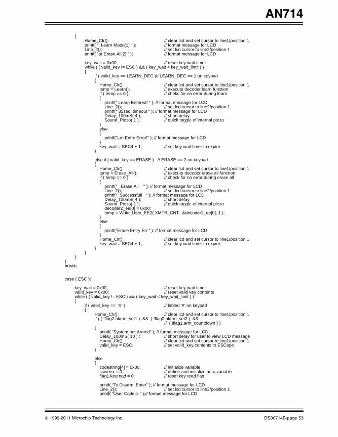
AN714
00714B.book Page 53 Friday, June 10, 2011 10:23 AM
{Home_Clr(); // clear lcd and set cursor to line1/position 1printf( “ Learn Mode[1] “ ); // format message for LCDLine_2(); // set lcd cursor to line2/position 1printf( “or Erase All[2] “ ); // format message for LCD
key_wait = 0x00; // reset key wait timerwhile ( ( valid_key != ESC ) && ( key_wait < key_wait_limit ) ){
if ( valid_key == LEARN_DEC )// LEARN_DEC == 1 on keypad{
Home_Clr(); // clear lcd and set cursor to line1/position 1temp = Learn(); // execute decoder learn functionif ( temp == 0 ) // chekc for no error during learn{
printf(“ Learn Entered! “ ); // format message for LCD Line_2(); // set lcd cursor to line2/position 1printf(“ 35sec. timeout “ ); // format message for LCD Delay_100mS( 4 ); // short delaySound_Piezo( 1 ); // quick toggle of internal piezo
}else{
printf(“Lrn Entry Error!” ); // format message for LCD }key_wait = SEC4 + 1; // set key wait timer to expire
}
else if ( valid_key == ERASE ) // ERASE == 2 on keypad{
Home_Clr(); // clear lcd and set cursor to line1/position 1temp = Erase_All(); // execute decoder erase all functionif ( temp == 0 ) // check for no error during erase all{
printf(“ Erase All “ ); // format message for LCD Line_2(); // set lcd cursor to line2/position 1printf(“ Successful! “ ); // format message for LCD Delay_100mS( 4 ); // short delaySound_Piezo( 1 ); // quick toggle of internal piezodecoder2_ee[0] = 0x00;temp = Write_User_EE2( XMTR_CNT, &decoder2_ee[0], 1 );
}else{
printf(“Erase Entry Err “ ); // format message for LCD }Home_Clr(); // clear lcd and set cursor to line1/position 1key_wait = SEC4 + 1; // set key wait timer to expire
}}
}}break;
case ( ESC ):
key_wait = 0x00; // reset key wait timervalid_key = 0x00; // reset valid key contents while ( ( valid_key != ESC ) && ( key_wait < key_wait_limit ) ){
if ( valid_key == ‘#’ ) // labled ‘#’ on keypad{
Home_Clr(); // clear lcd and set cursor to line1/position 1if ( ( !flag2.alarm_set1 ) && ( !flag2.alarm_set2 ) &&
// ( !flag1.arm_countdown ) ) {
printf( “System not Armed” ); // format message for LCDDelay_100mS( 10 ) ; // short delay for user to view LCD messageHome_Clr(); // clear lcd and set cursor to line1/position 1valid_key = ESC; // set valid_key contents to ESCape
}
else{
codestring[4] = 0x00; // initialize variablecsindex = 0; // define and initialize auto variableflag1.keyread = 0; // reset key read flag
printf( “To Disarm..Enter” ); // format message for LCDLine_2(); // set lcd cursor to line2/position 1printf( “User Code-> “ );// format message for LCD
© 1999-2011 Microchip Technology Inc. DS00714B-page 53
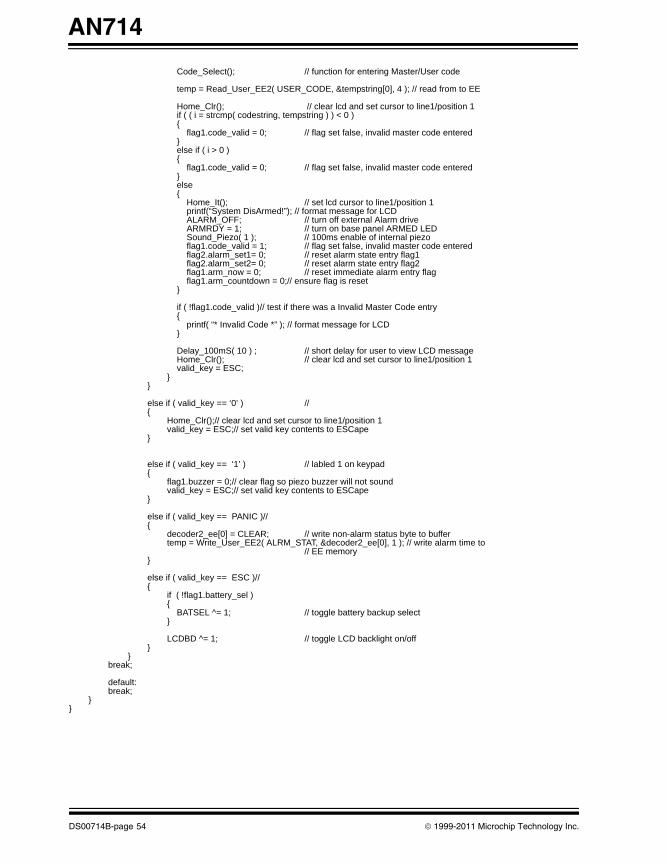
AN714
00714B.book Page 54 Friday, June 10, 2011 10:23 AM
Code_Select(); // function for entering Master/User code
temp = Read_User_EE2( USER_CODE, &tempstring[0], 4 ); // read from to EE
Home_Clr(); // clear lcd and set cursor to line1/position 1if ( ( i = strcmp( codestring, tempstring ) ) < 0 ){
flag1.code_valid = 0; // flag set false, invalid master code entered}else if ( i > 0 ){
flag1.code_valid = 0; // flag set false, invalid master code entered}else{
Home_It(); // set lcd cursor to line1/position 1printf(“System DisArmed!”); // format message for LCDALARM_OFF; // turn off external Alarm driveARMRDY = 1; // turn on base panel ARMED LEDSound_Piezo( 1 ); // 100ms enable of internal piezoflag1.code_valid = 1; // flag set false, invalid master code enteredflag2.alarm_set1= 0; // reset alarm state entry flag1flag2.alarm_set2= 0; // reset alarm state entry flag2flag1.arm_now = 0; // reset immediate alarm entry flagflag1.arm_countdown = 0;// ensure flag is reset
}
if ( !flag1.code_valid )// test if there was a Invalid Master Code entry{
printf( “* Invalid Code *” ); // format message for LCD}
Delay_100mS( 10 ) ; // short delay for user to view LCD messageHome_Clr(); // clear lcd and set cursor to line1/position 1valid_key = ESC;
}}
else if ( valid_key == ‘0’ ) // {
Home_Clr();// clear lcd and set cursor to line1/position 1valid_key = ESC;// set valid key contents to ESCape
}
else if ( valid_key == ‘1’ ) // labled 1 on keypad{
flag1.buzzer = 0;// clear flag so piezo buzzer will not soundvalid_key = ESC;// set valid key contents to ESCape
}
else if ( valid_key == PANIC )// {
decoder2_ee[0] = CLEAR; // write non-alarm status byte to buffertemp = Write_User_EE2( ALRM_STAT, &decoder2_ee[0], 1 ); // write alarm time to
// EE memory}
else if ( valid_key == ESC )// {
if ( !flag1.battery_sel ){
BATSEL ^= 1; // toggle battery backup select}
LCDBD ^= 1; // toggle LCD backlight on/off}
}break;
default:break;
}}
DS00714B-page 54 © 1999-2011 Microchip Technology Inc.
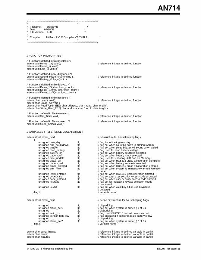
AN714
00714B.book Page 55 Friday, June 10, 2011 10:23 AM
/********************************************************************** ** Filename: prockey.h ** Date: 07/18/99 ** File Version: 1.00 ** ** Compiler: Hi-Tech PIC C Compiler V7.83 PL3 ** **********************************************************************/
// FUNCTION PROTOTYPES
/* Functions defined in file baselcd.c */extern void Home_Clr( void ); // reference linkage to defined functionextern void Home_It( void );extern void Line_2( void );
/* Functions defined in file diagfunc.c */extern void Sound_Piezo( char ontime ); // reference linkage to defined functionextern void Battery_Voltage( void );
/* Functions defined in file delays.c */extern void Delay_1S( char loop_count ); // reference linkage to defined functionextern void Delay_100mS( char loop_count );extern void Delay_1mS( char loop_count );
/* Functions defined in file hcsdec.c */extern char Learn( void ); // reference linkage to defined functionextern char Erase_All( void );extern char Read_User_EE2( char address, char * rdptr, char length );extern char Write_User_EE2( char address, char * wrptr, char length );
/* Function defined in file timeset.c */extern void Set_Time( void ); // reference linkage to defined function
/* Function defined in file codesel.c */ // reference linkage to defined functionextern void Code_Select( void );
// VARIABLES ( REFERENCE DECLARATION )
extern struct event_bits1 // bit structure for housekeeping flags {
unsigned new_day :1; // flag for indicating new dayunsigned arm_countdown :1; // flag set when counting down to arming systemunsigned buzzer :1; // flag set when piezo buzzer will sound when calledunsigned read_battery :1; // flag used for read battery voltageunsigned battery_on :1; // flag set when battery source is selectedunsigned battery_off :1; // flag set when battery is not selectedunsigned time_update :1; // flag used for updating LCD and E2 Memoryunsigned erase_all :1; // flag set when HCS515 erase all operation completeunsigned battery_sel :1; // flag set when battery source is selectedunsigned erase_entered :1; // flag set when HCS515 erase all operation enteredunsigned arm_now :1; // flag set when system is immediately armed w/o user
// codeunsigned learn_entered :1; // flag set when HCS515 learn operation enteredunsigned code_valid :1; // flag set after user security access code acceptedunsigned code_entered :1; // flag set when user security access code enteredunsigned keyread :1; // flag set for indicating keypad selection needs
// processedunsigned keyhit :1; // flag set when valid key hit on 4x4 keypad is
// detected} flag1; // variable name
extern struct event_bits2 // define bit structure for housekeeping flags{
unsigned :1; // bit paddingunsigned alarm_set1 :1; // flag set when system is armed ( 1 of 2 )unsigned :6; // bit padding unsigned valid_rcv :1; // flag used if HCS515 demod data is correctunsigned sensor_batt_low :1; // flag indicating if sensor module battery is lowunsigned :5; // bit paddingunsigned alarm_set2 :1; // flag set when system is armed ( 2 of 2 )
} flag2; // variable name
extern char porta_image; // reference linkage to defined variable in bank0extern char hours; // reference linkage to defined variable in bank0extern char minutes; // reference linkage to defined variable in bank0
© 1999-2011 Microchip Technology Inc. DS00714B-page 55
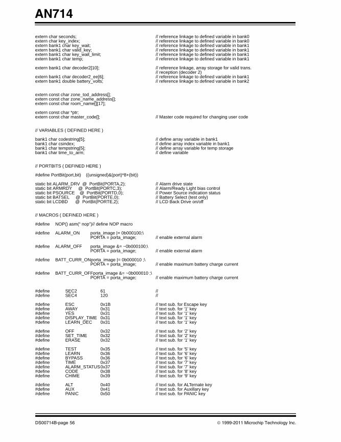
AN714
00714B.book Page 56 Friday, June 10, 2011 10:23 AM
extern char seconds; // reference linkage to defined variable in bank0extern char key_index; // reference linkage to defined variable in bank0extern bank1 char key_wait; // reference linkage to defined variable in bank1extern bank1 char valid_key; // reference linkage to defined variable in bank1extern bank1 char key_wait_limit; // reference linkage to defined variable in bank1extern bank1 char temp; // reference linkage to defined variable in bank1
extern bank1 char decoder2[10]; // reference linkage, array storage for valid trans.// reception (decoder 2)
extern bank1 char decoder2_ee[6]; // reference linkage to defined variable in bank1extern bank1 double battery_volts; // reference linkage to defined variable in bank2
extern const char zone_tod_address[];extern const char zone_name_address[];extern const char room_name[][17];
extern const char *ptr;extern const char master_code[]; // Master code required for changing user code
// VARIABLES ( DEFINED HERE )
bank1 char codestring[5]; // define array variable in bank1bank1 char csindex; // define array index variable in bank1bank1 char tempstring[5]; // define array variable for temp storagebank1 char time_to_arm; // define variable
// PORTBITS ( DEFINED HERE )
#define PortBit(port,bit) ((unsigned)&(port)*8+(bit))
static bit ALARM_DRV @ PortBit(PORTA,2); // Alarm drive statestatic bit ARMRDY @ PortBit(PORTC,3); // Alarm/Ready Light bias controlstatic bit PSOURCE @ PortBit(PORTD,0); // Power Source indication statusstatic bit BATSEL @ PortBit(PORTE,0); // Battery Select (test only)static bit LCDBD @ PortBit(PORTE,2); // LCD Back Drive on/off
// MACROS ( DEFINED HERE )
#define NOP() asm(“ nop”)// define NOP macro
#define ALARM_ON porta_image |= 0b000100;\PORTA = porta_image; // enable external alarm
#define ALARM_OFF porta_image &= ~0b000100;\PORTA = porta_image; // enable external alarm
#define BATT_CURR_ONporta_image |= 0b000010 ;\PORTA = porta_image; // enable maximum battery charge current
#define BATT_CURR_OFFporta_image &= ~0b000010 ;\PORTA = porta_image; // enable maximum battery charge current
#define SEC2 61 //#define SEC4 120 //
#define ESC 0x1B // text sub. for Escape key#define AWAY 0x31 // text sub. for ‘1’ key#define YES 0x31 // text sub. for ‘1’ key#define DISPLAY_TIME 0x31 // text sub. for ‘1’ key#define LEARN_DEC 0x31 // text sub. for ‘1’ key
#define OFF 0x32 // text sub. for ‘2’ key#define SET_TIME 0x32 // text sub. for ‘2’ key#define ERASE 0x32 // text sub. for ‘1’ key
#define TEST 0x35 // text sub. for ‘5’ key#define LEARN 0x36 // text sub. for ‘6’ key#define BYPASS 0x36 // text sub, for ‘6’ key#define TIME 0x37 // text sub. for ‘7’ key#define ALARM_STATUS0x37 // text sub. for ‘7’ key#define CODE 0x38 // text sub. for ‘8’ key#define CHIME 0x39 // text sub. for ‘9’ key
#define ALT 0x40 // text sub. for ALTernate key#define AUX 0x41 // text sub. for Auxillary key#define PANIC 0x50 // text sub. for PANIC key
DS00714B-page 56 © 1999-2011 Microchip Technology Inc.
AN714
00714B.book Page 57 Friday, June 10, 2011 10:23 AM
/********************************************************************** ** Wireless Home Security with Keeloq and the PIC MCU** ************************************************************************ ** Filename: proctran.c ** Date: 07/18/99 ** File Version: 1.00 ** ** Compiler: Hi-Tech PIC C Compiler V7.83 PL3 ** ** Author: Richard L. Fischer ** Company: Microchip Technology Incorporated ** ************************************************************************ ** Files required: ** ** pic.h ** proctran.h ** hcs515ee.h ** errcode.h ** ************************************************************************ ** Notes: The routines within this file are required for ** determining what type of transmission has been received ** from the HCS515 decoder(s). ** ** Currently only 1 decoder is implemented. ** **********************************************************************/
#include <pic.h>#include “proctran.h” // function prototypes, defines..#include “hcs515ee.h”
bit alarm_detect; // define bitbit ok_detect; // define bitbit test_detect; // define bit
void Read_Decoder_Trans( void ){
char maj_detect = 0; // initialize variable for majority detect
alarm_detect = 0; // initialize bitok_detect = 0; // initialize bittest_detect = 0; // initialize bitflag2.valid_rcv = 0; // reset valid reception flag
Delay_1mS( 2 ); // wait 2mSif ( HCSDATA2 ) // is data line high?
maj_detect ++; // yes so increment majority detect count
Delay_1mS( 2 ); // wait 2mSif ( HCSDATA2 ) // is data line high?
maj_detect ++; // yes so increment majority detect count
Delay_1mS( 20 ); // wait 20mS
if ( HCSDATA2 ) // is data line high?maj_detect ++; // yes so increment majority detect count
Delay_1mS( 2 ); // wait 2mSif ( HCSDATA2 ) // is data line high?
maj_detect ++; // yes so increment majority detect count
if ( maj_detect == 4 ) // majority detect == 4?{
Read_Trans( 10 ); // can read up to 10 bytes of received message
/* Test here if received function codes indicate a possible “ALARM” transmission */if ( (( decoder2[0] & 0x78 ) == 0x08 ) && (( decoder2[5] & 0xF0 ) == 0x20 ) ){
alarm_detect = 1;flag2.valid_rcv = 1; // if here then there is a valid reception
}
/* Test here if received function codes indicate a “TEST/LEARN” transmission */else if ( (( decoder2[0] & 0x78 ) == 0x10 ) && (( decoder2[5] & 0xF0 ) == 0x40 ) ){
© 1999-2011 Microchip Technology Inc. DS00714B-page 57
AN714
00714B.book Page 58 Friday, June 10, 2011 10:23 AM
test_detect = 1;flag2.valid_rcv = 1; // if here then there is a valid reception
}
/* Test here if received function codes indicate a possible “OKAY” transmission */else if ( (( decoder2[0] & 0x78 ) == 0x18 ) && (( decoder2[5] & 0xF0 ) == 0x60 ) ){
ok_detect = 1;flag2.valid_rcv = 1; // if here then there is a valid reception
}maj_detect = 0; // reset majority detect count
}
if ( flag2.valid_rcv ) // test if there was a valid transmission{
decoder2_ee[0] = hours; // write hours count to buffer for EE writedecoder2_ee[1] = minutes; // write minutes count to buffer for EE writedecoder2_ee[2] = seconds; // write seconds count to buffer for EE write
if ( alarm_detect ){
if ( ( flag2.alarm_set1 == 1 ) && ( flag2.alarm_set2 == 1 ) ) // is system ARMED?{
ALARM_ON; // yes, so turn on external alarmSound_Piezo( 5 ); // toggle internal piezo for 500mSDelay_100mS( 1 ); // short delaySound_Piezo( 1 ); // toggle internal piezo for 100mSdecoder2_ee[3] = ALRM; // write “ALARM ON” status byte to buffer for EE write
}else // if here zone trip occurred but system is NOT ARMED{
ALARM_OFF; // ensure alarm is offSound_Piezo( 1 ); // toggle internal piezo for 100mSDelay_100mS( 1 ); // short delaySound_Piezo( 5 ); // toggle internal piezo for 500mSdecoder2_ee[3] = CLEAR; // write “CLEAR” status byte to buffer for EE write
}temp = Write_User_EE2( ALRM_HRS, &decoder2_ee[0], 4 ); // write alarm condition status
// and time to EE }
else if ( test_detect ){
Sound_Piezo( 1 );// toggle internal piezo for 100mSdecoder2_ee[3] = TST_LRN; // write “TEST/LEARN” status byte to buffer for EE
// write}
else if ( ok_detect ){
Sound_Piezo( 1 ); // toggle internal piezo for 100mSDelay_100mS( 1 ); // short delaySound_Piezo( 1 ); // toggle internal piezo for 100mSdecoder2_ee[3] = OKAY; // write “OKAY” status byte to buffer for EE write
}
temp = Write_User_EE2( LAST_XMIT, &decoder2_ee[3], 1 ); // write last transmission type // code to EE
if ( ( decoder2[0] & 0x04 ) ) // test for Vlow bit in sensor module transmission {
decoder2_ee[3] = LOW; // write battery “LOW” status code to buffer for EE // write
flag2.sensor_batt_low = 1; // set flag indicating zone battery is low}else{
decoder2_ee[3] = HIGH; // write battery “HIGH” status code to buffer for EE // write
flag2.sensor_batt_low = 0; // reset flag}
/* Write battery status and respective time stamp to appropriate zone tag in EE memory */temp = ( decoder2[1] - 1) & 0x0F;// determine which transmitter block was receivedtemp = Write_User_EE2( zone_tod_address[temp], &decoder2_ee[0], 4 ); // write alarm
// time to EE memory}
}
DS00714B-page 58 © 1999-2011 Microchip Technology Inc.
AN714
00714B.book Page 59 Friday, June 10, 2011 10:23 AM
/********************************************************************** ** Filename: proctran.h ** Date: 07/18/99 ** File Version: 1.00 ** ** Compiler: Hi-Tech PIC C Compiler V7.83 PL3 ** **********************************************************************/
// FUNCTION PROTOTYPES
/* Functions defined in file delays.c */extern void Delay_100mS( char loop_count ); // refercene linkage to defined functionextern void Delay_10mS( char loop_count );extern void Delay_1mS( char loop_count );
/* Function defined is file diagfunc.c */ extern void Sound_Piezo( char ontime ); // reference linkage to defined function
/* Functions defined in file hcsdec.c */ extern void Read_Trans( char length ); // reference linkage to defined functionextern char Write_User_EE2( char address, char * wrptr, char length );extern char Read_User_EE2( char address, char * rdptr, char length );
const char zone_tod_address[] = { 0x8A, 0x91, 0x98, 0x9F, 0xA6, 0xAD, 0xB4 };
// VARIABLES ( REFERENCE DECLARATION )
extern struct event_bits2 // define bit structure for housekeeping flags{
unsigned :1; // bit padding unsigned alarm_set1 :1; // flag set when system is armed ( 1 of 2 )unsigned :6; // bit padding unsigned valid_rcv :1; // flag used if HCS515 demod data is correct unsigned sensor_batt_low :1; // flag indicating if sensor module battery is lowunsigned :5; // bit paddingunsigned alarm_set2 :1; // flag set when system is armed ( 2 of 2 )
} flag2; // variable name
extern char porta_image; // reference linkage to defined variable (SFR)extern char hours; // reference linkage to defined variable in bank0extern char minutes; // reference linkage to defined variable in bank0extern char seconds; // reference linkage to defined variable in bank0
extern bank1 char decoder2[10]; // reference linkage, array storage for valid trans.// reception (decoder 2)
extern bank1 char decoder1_ee[6]; // reference linkage to defined array variable in // bank1// reception (decoder 2)
extern bank1 char decoder2_ee[6]; // reference linkage to defined array variable in // bank1
extern bank1 char temp; // reference linkage to defined variable in bank1
// PORTBITS ( DEFINED HERE )
#define PortBit(port,bit) ((unsigned)&(port)*8+(bit))
static bit HCSDATA2 @ PortBit(PORTC,5); // declare bit for HCS515 data line
// MACROS ( DEFINED HERE )
#define NOP()asm(“ nop”) // define NOP macro
#define ALARM_ON porta_image |= 0b000100;\ PORTA = porta_image; // enable external alarm
#define ALARM_OFF porta_image &= ~0b000100;\ PORTA = porta_image; // enable external alarm
© 1999-2011 Microchip Technology Inc. DS00714B-page 59
AN714
00714B.book Page 60 Friday, June 10, 2011 10:23 AM
/********************************************************************** ** Wireless Home Security with Keeloq and the PIC MCU** ************************************************************************ ** Filename: timeset.c ** Date: 07/18/99 ** File Version: 1.00 ** ** Compiler: Hi-Tech PIC C Compiler V7.83 PL3 ** ** Author: Richard L. Fischer ** Company: Microchip Technology Incorporated ** ************************************************************************ ** Files required: ** ** pic.h ** stdio.h ** time.h ** ************************************************************************ ** Notes: The routine within this file is used for ** setting the time-of-day via 4x4 keypad selections. ** ** Key Function ** ** 1 Increment hours count ** 4 Decrement hours count ** ** 2 Increment minutes count ** 5 Decrement minutes count ** ** 3 Increment seconds count ** 6 Decrement seconds count ** ** **********************************************************************/
#include <pic.h> // processor if/def file#include <stdio.h>#include “time.h” // function prototypes, variables, defines..
void Set_Time( void ){
TMR1IE = 0; // disable real-time clock interruptsHome_Clr(); // clear lcd and set cursor to line1/position 1
while ( valid_key != ESC ){
Line_2(); // set lcd cursor to line2/position 1Delay_10mS( 15 ); // short delayprintf( “Time-> %02u:%02u:%02u” ,hours,minutes,seconds );
switch ( valid_key ) // evaluate expression {
case ( ‘1’ ): // test if hours will be incrementedhours++; // increment hoursif ( hours > 23 ) // test if hours will roll over{
hours = 0x00; // yes, so reset hours}break; // exit from switch evaluation
case ( ‘2’ ): // test if minutes will be incrementedminutes++; // increment minutesif ( minutes > 59 ) // test if minutes will roll over{
minutes = 0x00; // yes, so reset minutes}break; // exit from switch evaluation
case ( ‘3’ ): // test if seconds will be incremented
seconds++; // increment secondsif ( seconds > 59 ) // test if seconds will roll over{
seconds = 0x00; // yes, so reset seconds}
DS00714B-page 60 © 1999-2011 Microchip Technology Inc.
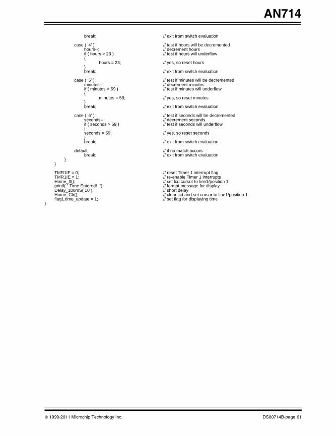
AN714
00714B.book Page 61 Friday, June 10, 2011 10:23 AM
break; // exit from switch evaluation
case ( ‘4’ ): // test if hours will be decrementedhours--; // decrement hoursif ( hours > 23 ) // test if hours will underflow{
hours = 23; // yes, so reset hours}break; // exit from switch evaluation
case ( ‘5’ ): // test if minutes will be decrementedminutes--; // decrement minutesif ( minutes > 59 ) // test if minutes will underflow{
minutes = 59; // yes, so reset minutes}break; // exit from switch evaluation
case ( ‘6’ ): // test if seconds will be decremented
seconds--; // decrement secondsif ( seconds > 59 ) // test if seconds will underflow{seconds = 59; // yes, so reset seconds}break; // exit from switch evaluation
default: // if no match occursbreak; // exit from switch evaluation
}}
TMR1IF = 0; // reset Timer 1 interrupt flag TMR1IE = 1; // re-enable Timer 1 interruptsHome_It(); // set lcd cursor to line1/position 1printf( “ Time Entered! “); // format message for displayDelay_100mS( 10 ); // short delayHome_Clr(); // clear lcd and set cursor to line1/position 1flag1.time_update = 1; // set flag for displaying time
}
© 1999-2011 Microchip Technology Inc. DS00714B-page 61
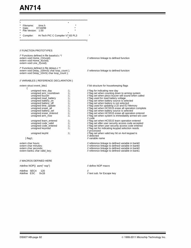
AN714
00714B.book Page 62 Friday, June 10, 2011 10:23 AM
/********************************************************************** ** Filename: time.h ** Date: 07/18/99 ** File Version: 1.00 ** ** Compiler: Hi-Tech PIC C Compiler V7.83 PL3 ** **********************************************************************/
// FUNCTION PROTOTYPES
/* Functions defined in file baselcd.c */extern void Home_Clr(void); // reference linkage to defined functionextern void Home_It(void);extern void Line_2(void);
/* Functions defined in file delays.c */extern void Delay_100mS( char loop_count ); // reference linkage to defined functionextern void Delay_10mS( char loop_count );
// VARIABLES ( REFERENCE DECLARATION )
extern struct event_bits1 // bit structure for housekeeping flags {
unsigned new_day :1; // flag for indicating new dayunsigned arm_countdown :1; // flag set when counting down to arming systemunsigned buzzer :1; // flag set when piezo buzzer will sound when calledunsigned read_battery :1; // flag used for read battery voltageunsigned battery_on :1; // flag set when battery source is selectedunsigned battery_off :1; // flag set when battery is not selectedunsigned time_update :1; // flag used for updating LCD and E2 Memoryunsigned erase_all :1; // flag set when HCS515 erase all operation completeunsigned battery_sel :1; // flag set when battery source is selectedunsigned erase_entered :1; // flag set when HCS515 erase all operation enteredunsigned arm_now :1; // flag set when system is immediately armed w/o user
// codeunsigned learn_entered :1; // flag set when HCS515 learn operation enteredunsigned code_valid :1; // flag set after user security access code acceptedunsigned code_entered :1; // flag set when user security access code enteredunsigned keyread :1; // flag set for indicating keypad selection needs
// processedunsigned keyhit :1; // flag set when valid key hit on 4x4 keypad is
// detected} flag1; // variable name
extern char hours; // reference linkage to defined variable in bank0extern char minutes; // reference linkage to defined variable in bank0 extern char seconds; // reference linkage to defined variable in bank0extern bank1 char valid_key; // reference linkage to defined variable in bank1
// MACROS DEFINED HERE
#define NOP() asm(“ nop”) // define NOP macro
#define SEC4 120 //#define ESC 0x1B // text sub. for Escape key
DS00714B-page 62 © 1999-2011 Microchip Technology Inc.
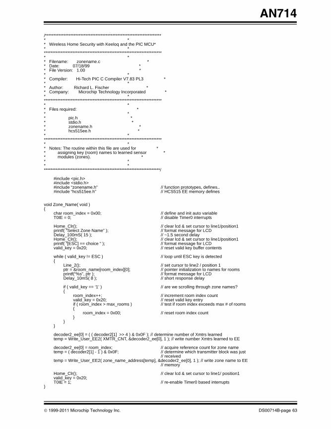
AN714
00714B.book Page 63 Friday, June 10, 2011 10:23 AM
/********************************************************************** ** Wireless Home Security with Keeloq and the PIC MCU** ************************************************************************ ** Filename: zonename.c ** Date: 07/18/99 ** File Version: 1.00 ** ** Compiler: Hi-Tech PIC C Compiler V7.83 PL3 ** ** Author: Richard L. Fischer ** Company: Microchip Technology Incorporated ** ************************************************************************ ** Files required: ** ** pic.h ** stdio.h ** zonename.h ** hcs515ee.h ** ************************************************************************ ** Notes: The routine within this file are used for ** assigning key (room) names to learned sensor ** modules (zones). ** ** **********************************************************************/
#include <pic.h>#include <stdio.h>#include “zonename.h” // function prototypes, defines..#include “hcs515ee.h” // HCS515 EE memory defines
void Zone_Name( void ){
char room_index = 0x00; // define and init auto variableT0IE = 0; // disable Timer0 interrupts
Home_Clr(); // clear lcd & set cursor to line1/position1printf( “Select Zone Name” ); // format message for LCDDelay_100mS( 15 ); // ~1.5 second delayHome_Clr(); // clear lcd & set cursor to line1/position1printf( “[ESC] == choice “ ); // format message for LCDvalid_key = 0x20; // reset valid key buffer contents
while ( valid_key != ESC ) // loop until ESC key is detected{
Line_2(); // set cursor to line2 / position 1ptr = &room_name[room_index][0]; // pointer initialization to names for roomsprintf(“%s”, ptr ); // format message for LCDDelay_10mS( 8 ); // short response delay
if ( valid_key == ‘1’ ) // are we scrolling through zone names?{
room_index++; // increment room index countvalid_key = 0x20; // reset valid key entryif ( room_index > max_rooms ) // test if room index exceeds max # of rooms{
room_index = 0x00; // reset room index count}
}}
decoder2_ee[0] = ( ( decoder2[1] >> 4 ) & 0x0F ); // determine number of Xmtrs learnedtemp = Write_User_EE2( XMTR_CNT, &decoder2_ee[0], 1 ); // write number Xmtrs learned to EE
decoder2_ee[0] = room_index; // acquire reference count for zone nametemp = ( decoder2[1] - 1 ) & 0x0F; // determine which transmitter block was just
// receivedtemp = Write_User_EE2( zone_name_address[temp], &decoder2_ee[0], 1 ); // write zone name to EE
// memory
Home_Clr(); // clear lcd & set cursor to line1/ position1valid_key = 0x20;T0IE = 1; // re-enable Timer0 based interrupts
}
© 1999-2011 Microchip Technology Inc. DS00714B-page 63
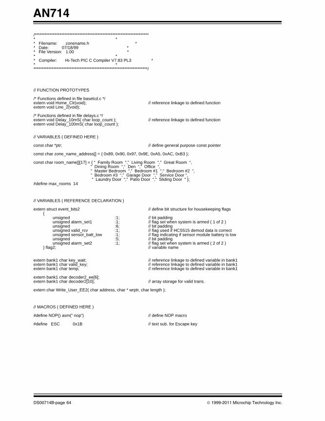
AN714
00714B.book Page 64 Friday, June 10, 2011 10:23 AM
/********************************************************************** ** Filename: zonename.h ** Date: 07/18/99 ** File Version: 1.00 ** ** Compiler: Hi-Tech PIC C Compiler V7.83 PL3 ** **********************************************************************/
// FUNCTION PROTOTYPES
/* Functions defined in file baselcd.c */extern void Home_Clr(void); // reference linkage to defined functionextern void Line_2(void); /* Functions defined in file delays.c */extern void Delay_10mS( char loop_count ); // reference linkage to defined functionextern void Delay_100mS( char loop_count );
// VARIABLES ( DEFINED HERE )
const char *ptr; // define general purpose const pointer
const char zone_name_address[] = { 0x89, 0x90, 0x97, 0x9E, 0xA5, 0xAC, 0xB3 };
const char room_name[][17] = { “ Family Room “,” Living Room “,” Great Room “, ” Dining Room “,“ Den “,” Office “, ” Master Bedroom “,” Bedroom #1 “,“ Bedroom #2 “, ” Bedroom #3 “,” Garage Door “,” Service Door “, “ Laundry Door “,” Patio Door “,” Sliding Door “ };
#define max_rooms 14
// VARIABLES ( REFERENCE DECLARATION )
extern struct event_bits2 // define bit structure for housekeeping flags{
unsigned :1; // bit paddingunsigned alarm_set1 :1; // flag set when system is armed ( 1 of 2 )unsigned :6; // bit padding unsigned valid_rcv :1; // flag used if HCS515 demod data is correct unsigned sensor_batt_low :1; // flag indicating if sensor module battery is lowunsigned :5; // bit paddingunsigned alarm_set2 :1; // flag set when system is armed ( 2 of 2 )
} flag2; // variable name
extern bank1 char key_wait; // reference linkage to defined variable in bank1 extern bank1 char valid_key; // reference linkage to defined variable in bank1extern bank1 char temp; // reference linkage to defined variable in bank1
extern bank1 char decoder2_ee[6];extern bank1 char decoder2[10]; // array storage for valid trans.
extern char Write_User_EE2( char address, char * wrptr, char length );
// MACROS ( DEFINED HERE )
#define NOP() asm(“ nop”) // define NOP macro
#define ESC 0x1B // text sub. for Escape key
DS00714B-page 64 © 1999-2011 Microchip Technology Inc.
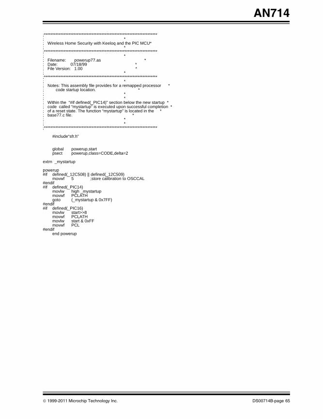
AN714
00714B.book Page 65 Friday, June 10, 2011 10:23 AM
;*********************************************************************; *; Wireless Home Security with Keeloq and the PIC MCU*; *;*********************************************************************; *; Filename: powerup77.as *; Date: 07/18/99 *; File Version: 1.00 *; *;*********************************************************************; *; Notes: This assembly file provides for a remapped processor *; code startup location. *; *; *; Within the “#if defined(_PIC14)” section below the new startup *; code called “mystartup” is executed upon successful completion *; of a reset state. The function “mystartup” is located in the *; base77.c file. *; *; *;*********************************************************************
#include“sfr.h”
global powerup,startpsect powerup,class=CODE,delta=2
extrn _mystartup
powerup#if defined(_12C508) || defined(_12C509)
movwf 5 ;store calibration to OSCCAL#endif#if defined(_PIC14)
movlw high _mystartupmovwf PCLATHgoto (_mystartup & 0x7FF)
#endif#if defined(_PIC16)
movlw start>>8movwf PCLATHmovlw start & 0xFFmovwf PCL
#endifend powerup
© 1999-2011 Microchip Technology Inc. DS00714B-page 65
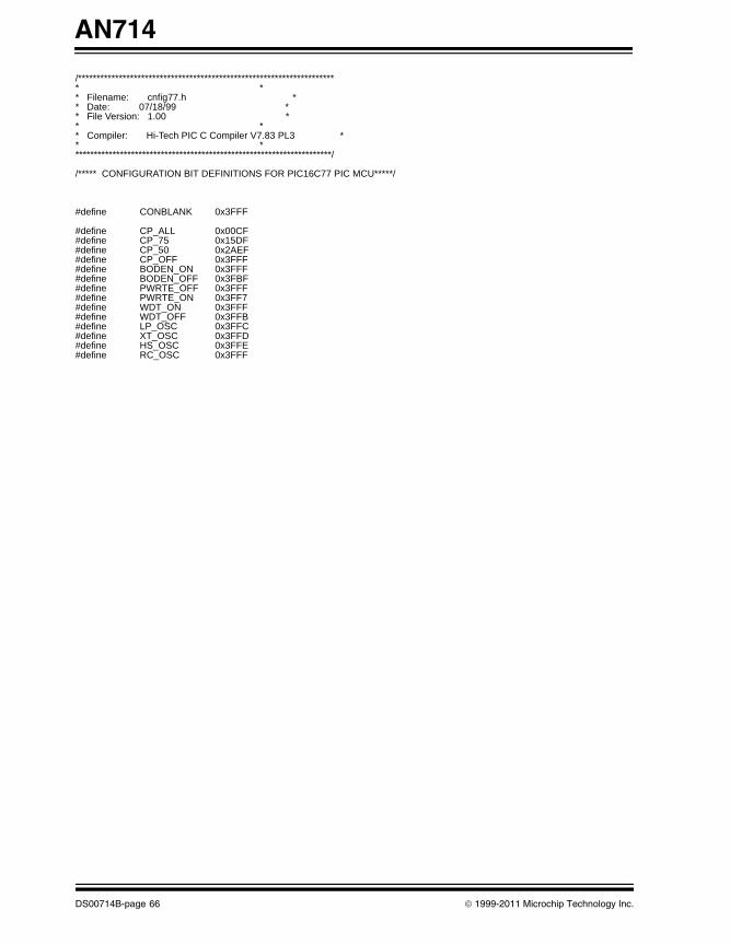
AN714
00714B.book Page 66 Friday, June 10, 2011 10:23 AM
/********************************************************************** ** Filename: cnfig77.h ** Date: 07/18/99 ** File Version: 1.00 ** ** Compiler: Hi-Tech PIC C Compiler V7.83 PL3 ** **********************************************************************/
/***** CONFIGURATION BIT DEFINITIONS FOR PIC16C77 PIC MCU*****/
#define CONBLANK 0x3FFF
#define CP_ALL 0x00CF#define CP_75 0x15DF#define CP_50 0x2AEF#define CP_OFF 0x3FFF#define BODEN_ON 0x3FFF#define BODEN_OFF 0x3FBF#define PWRTE_OFF 0x3FFF#define PWRTE_ON 0x3FF7#define WDT_ON 0x3FFF#define WDT_OFF 0x3FFB#define LP_OSC 0x3FFC#define XT_OSC 0x3FFD#define HS_OSC 0x3FFE#define RC_OSC 0x3FFF
DS00714B-page 66 © 1999-2011 Microchip Technology Inc.
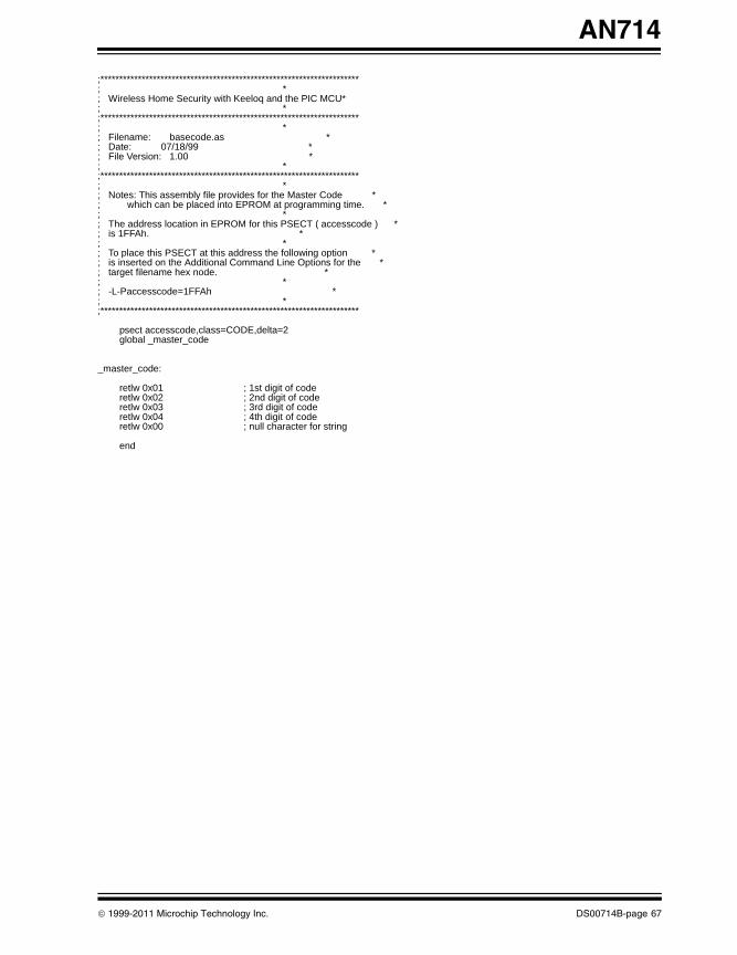
AN714
00714B.book Page 67 Friday, June 10, 2011 10:23 AM
;*********************************************************************; *; Wireless Home Security with Keeloq and the PIC MCU*; *;*********************************************************************; *; Filename: basecode.as *; Date: 07/18/99 *; File Version: 1.00 *; *;*********************************************************************; *; Notes: This assembly file provides for the Master Code *; which can be placed into EPROM at programming time. *; *; The address location in EPROM for this PSECT ( accesscode ) *; is 1FFAh. *; *; To place this PSECT at this address the following option *; is inserted on the Additional Command Line Options for the *; target filename hex node. *; *; -L-Paccesscode=1FFAh *; *;*********************************************************************
psect accesscode,class=CODE,delta=2global _master_code
_master_code:
retlw 0x01 ; 1st digit of coderetlw 0x02 ; 2nd digit of coderetlw 0x03 ; 3rd digit of coderetlw 0x04 ; 4th digit of coderetlw 0x00 ; null character for string
end
© 1999-2011 Microchip Technology Inc. DS00714B-page 67
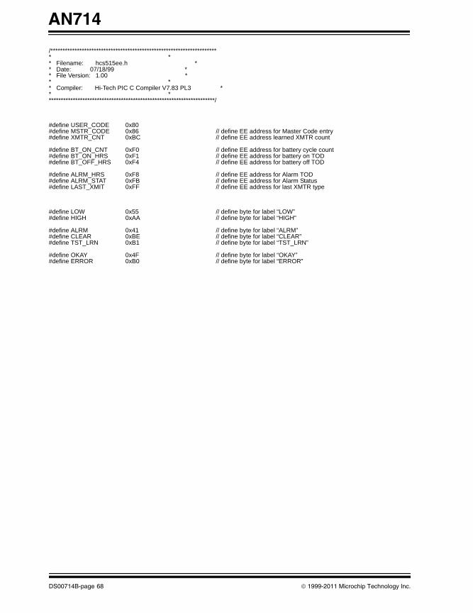
AN714
00714B.book Page 68 Friday, June 10, 2011 10:23 AM
/********************************************************************** ** Filename: hcs515ee.h ** Date: 07/18/99 ** File Version: 1.00 ** ** Compiler: Hi-Tech PIC C Compiler V7.83 PL3 ** **********************************************************************/
#define USER_CODE 0x80#define MSTR_CODE 0x86 // define EE address for Master Code entry#define XMTR_CNT 0xBC // define EE address learned XMTR count
#define BT_ON_CNT 0xF0 // define EE address for battery cycle count#define BT_ON_HRS 0xF1 // define EE address for battery on TOD#define BT_OFF_HRS 0xF4 // define EE address for battery off TOD
#define ALRM_HRS 0xF8 // define EE address for Alarm TOD#define ALRM_STAT 0xFB // define EE address for Alarm Status #define LAST_XMIT 0xFF // define EE address for last XMTR type
#define LOW 0x55 // define byte for label “LOW”#define HIGH 0xAA // define byte for label “HIGH”
#define ALRM 0x41 // define byte for label “ALRM”#define CLEAR 0xBE // define byte for label “CLEAR”#define TST_LRN 0xB1 // define byte for label “TST_LRN”
#define OKAY 0x4F // define byte for label “OKAY”#define ERROR 0xB0 // define byte for label “ERROR”
DS00714B-page 68 © 1999-2011 Microchip Technology Inc.
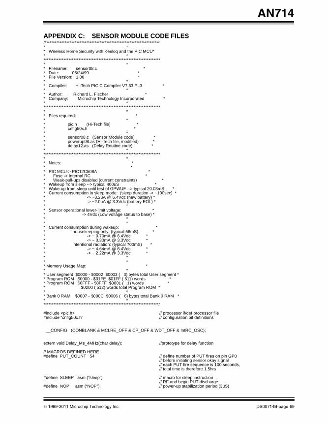
AN714
00714B.book Page 69 Friday, June 10, 2011 10:23 AM
APPENDIX C: SENSOR MODULE CODE FILES/********************************************************************** ** Wireless Home Security with Keeloq and the PIC MCU** ************************************************************************ ** Filename: sensor08.c ** Date: 05/24/99 ** File Version: 1.00 ** ** Compiler: Hi-Tech PIC C Compiler V7.83 PL3 ** ** Author: Richard L. Fischer ** Company: Microchip Technology Incorporated ** ************************************************************************ ** Files required: ** ** pic.h (Hi-Tech file) ** cnfig50x.h ** ** sensor08.c (Sensor Module code) ** powerup08.as (Hi-Tech file, modified) ** delay12.as (Delay Routine code) ** ************************************************************************ ** Notes: ** ** PIC MCU-> PIC12C508A ** Fosc -> Internal RC ** Weak-pull-ups disabled (current constraints) ** Wakeup from sleep --> typical 400uS ** Wake-up from sleep until test of GPWUF --> typical 20.03mS ** Current consumption in sleep mode: (sleep duration -> ~100sec) ** -> ~3.2uA @ 6.4Vdc (new battery) ** -> ~2.0uA @ 3.3Vdc (battery EOL) ** ** Sensor operational lower-limit voltage: ** -> 4Vdc (Low voltage status to base) ** ** ** Current consumption during wakeup: ** housekeeping only: (typical 56mS) ** -> ~ 0.70mA @ 6.4Vdc ** -> ~ 0.30mA @ 3.3Vdc ** intentional radiation: (typical 700mS) ** -> ~ 4.64mA @ 6.4Vdc ** -> ~ 2.22mA @ 3.3Vdc ** ** ** Memory Usage Map: ** ** User segment $0000 - $0002 $0003 ( 3) bytes total User segment ** Program ROM $0000 - $01FE $01FF ( 511) words ** Program ROM $0FFF - $0FFF $0001 ( 1) words ** $0200 ( 512) words total Program ROM ** ** Bank 0 RAM $0007 - $000C $0006 ( 6) bytes total Bank 0 RAM ** **********************************************************************/
#include <pic.h> // processor if/def processor file#include “cnfig50x.h” // configuration bit definitions
__CONFIG (CONBLANK & MCLRE_OFF & CP_OFF & WDT_OFF & IntRC_OSC);
extern void Delay_Ms_4MHz(char delay); //prototype for delay function
// MACROS DEFINED HERE#define PUT_COUNT 54 // define number of PUT fires on pin GP0
// before initiating sensor okay signal// each PUT fire sequence is 100 seconds, // total time is therefore 1.5hrs
#define SLEEP asm (“sleep”) // macro for sleep instruction// RF and begin PUT discharge
#define NOP asm (“NOP”); // power-up stabilization period (3uS)
© 1999-2011 Microchip Technology Inc. DS00714B-page 69
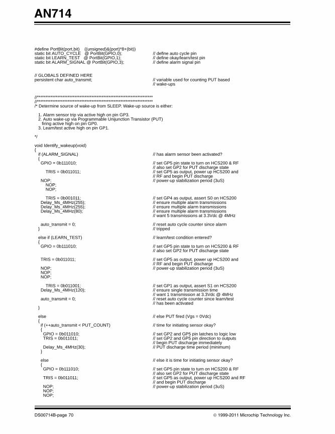
AN714
00714B.book Page 70 Friday, June 10, 2011 10:23 AM
#define PortBit(port,bit) ((unsigned)&(port)*8+(bit))static bit AUTO_CYCLE @ PortBit(GPIO,0); // define auto cycle pinstatic bit LEARN_TEST @ PortBit(GPIO,1); // define okay/learn/test pinstatic bit ALARM_SIGNAL @ PortBit(GPIO,3); // define alarm signal pin
// GLOBALS DEFINED HEREpersistent char auto_transmit; // variable used for counting PUT based
// wake-ups
//********************************************************************//********************************************************************/* Determine source of wake-up from SLEEP. Wake-up source is either:
1. Alarm sensor trip via active high on pin GP3. 2. Auto wake-up via Programmable Unijunction Transistor (PUT) firing active high on pin GP0. 3. Learn/test active high on pin GP1.
*/
void Identify_wakeup(void){ if (ALARM_SIGNAL) // has alarm sensor been activated? { GPIO = 0b111010; // set GP5 pin state to turn on HCS200 & RF
// also set GP2 for PUT discharge state TRIS = 0b011011; // set GP5 as output, power up HCS200 and
// RF and begin PUT discharge NOP; // power-up stabilization period (3uS)
NOP; NOP;
TRIS = 0b001011; // set GP4 as output, assert S0 on HCS200 Delay_Ms_4MHz(255); // ensure multiple alarm transmissions Delay_Ms_4MHz(255); // ensure multiple alarm transmissions Delay_Ms_4MHz(80); // ensure multiple alarm transmissions
// want 5 transmissions at 3.3Vdc @ 4MHz
auto_transmit = 0; // reset auto cycle counter since alarm } // tripped
else if (LEARN_TEST) // learn/test condition entered? { GPIO = 0b111010; // set GP5 pin state to turn on HCS200 & RF
// also set GP2 for PUT discharge state TRIS = 0b011011; // set GP5 as output, power up HCS200 and
// RF and begin PUT discharge NOP; // power-up stabilization period (3uS) NOP; NOP;
TRIS = 0b011001; // set GP1 as output, assert S1 on HCS200 Delay_Ms_4MHz(120); // ensure single transmission time
// want 1 transmission at 3.3Vdc @ 4MHz auto_transmit = 0; // reset auto cycle counter since learn/test
// has been activated }
else // else PUT fired (Vgs = 0Vdc) { if (++auto_transmit < PUT_COUNT) // time for initiating sensor okay? { GPIO = 0b011010; // set GP2 and GP5 pin latches to logic low TRIS = 0b011011; // set GP2 and GP5 pin direction to outputs
// begin PUT discharge immediately Delay_Ms_4MHz(30); // PUT discharge time period (minimum) }
else // else it is time for initiating sensor okay? { GPIO = 0b111010; // set GP5 pin state to turn on HCS200 & RF
// also set GP2 for PUT discharge state TRIS = 0b011011; // set GP5 as output, power up HCS200 and RF
// and begin PUT discharge NOP; // power-up stabilization period (3uS) NOP; NOP;
DS00714B-page 70 © 1999-2011 Microchip Technology Inc.
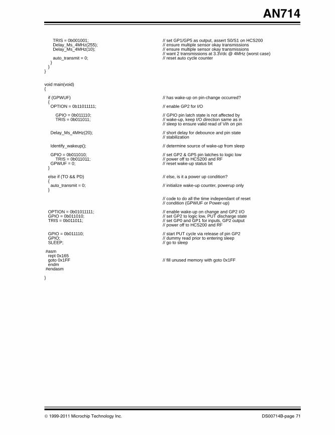
AN714
00714B.book Page 71 Friday, June 10, 2011 10:23 AM
TRIS = 0b001001; // set GP1/GP5 as output, assert S0/S1 on HCS200 Delay_Ms_4MHz(255); // ensure multiple sensor okay transmissions Delay_Ms_4MHz(10); // ensure multiple sensor okay transmissions
// want 2 transmissions at 3.3Vdc @ 4MHz (worst case) auto_transmit = 0; // reset auto cycle counter } } }
void main(void){
if (GPWUF) // has wake-up on pin-change occurred? { OPTION = 0b11011111; // enable GP2 for I/O
GPIO = 0b011110; // GPIO pin latch state is not affected by TRIS = 0b011011; // wake-up, keep I/O direction same as in
// sleep to ensure valid read of Vih on pin
Delay_Ms_4MHz(20); // short delay for debounce and pin state // stabilization
Identify_wakeup(); // determine source of wake-up from sleep
GPIO = 0b011010; // set GP2 & GP5 pin latches to logic low TRIS = 0b011011; // power off to HCS200 and RF
GPWUF = 0; // reset wake-up status bit }
else if (TO && PD) // else, is it a power up condition? { auto_transmit = 0; // initialize wake-up counter, powerup only }
// code to do all the time independant of reset // condition (GPWUF or Power-up)
OPTION = 0b01011111; // enable wake-up on change and GP2 I/O GPIO = 0b011010; // set GP2 to logic low, PUT discharge state TRIS = 0b011011; // set GP0 and GP1 for inputs, GP2 output
// power off to HCS200 and RF
GPIO = 0b011110; // start PUT cycle via release of pin GP2 GPIO; // dummy read prior to entering sleep SLEEP; // go to sleep
#asm rept 0x165 goto 0x1FF // fill unused memory with goto 0x1FF endm #endasm
}
© 1999-2011 Microchip Technology Inc. DS00714B-page 71
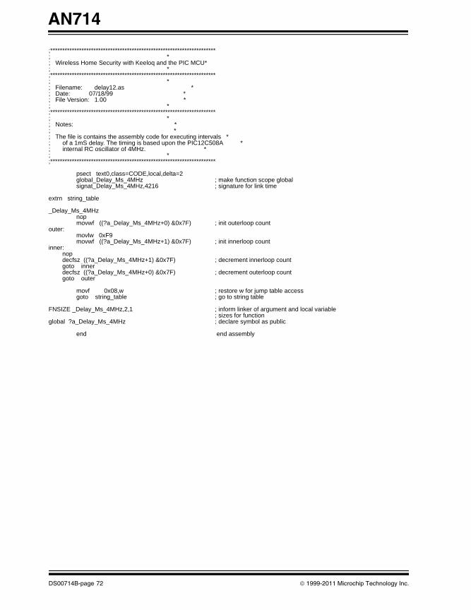
AN714
00714B.book Page 72 Friday, June 10, 2011 10:23 AM
;*********************************************************************; *; Wireless Home Security with Keeloq and the PIC MCU*; *;*********************************************************************; *; Filename: delay12.as *; Date: 07/18/99 *; File Version: 1.00 *; *;*********************************************************************; *; Notes: *; *; The file is contains the assembly code for executing intervals *; of a 1mS delay. The timing is based upon the PIC12C508A *; internal RC oscillator of 4MHz. *; *;*********************************************************************
psect text0,class=CODE,local,delta=2global_Delay_Ms_4MHz ; make function scope globalsignat_Delay_Ms_4MHz,4216 ; signature for link time
extrn string_table
_Delay_Ms_4MHznopmovwf ((?a_Delay_Ms_4MHz+0) &0x7F) ; init outerloop count
outer:movlw 0xF9movwf ((?a_Delay_Ms_4MHz+1) &0x7F) ; init innerloop count
inner: nop decfsz ((?a_Delay_Ms_4MHz+1) &0x7F) ; decrement innerloop count goto inner decfsz ((?a_Delay_Ms_4MHz+0) &0x7F) ; decrement outerloop count goto outer
movf 0x08,w ; restore w for jump table accessgoto string_table ; go to string table
FNSIZE _Delay_Ms_4MHz,2,1 ; inform linker of argument and local variable; sizes for function
global ?a_Delay_Ms_4MHz ; declare symbol as public
end end assembly
DS00714B-page 72 © 1999-2011 Microchip Technology Inc.
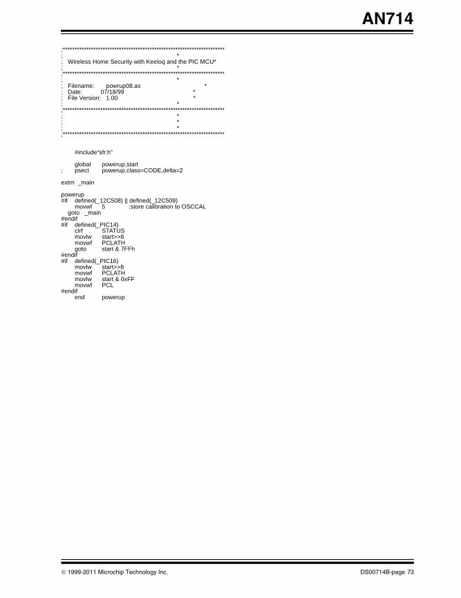
AN714
00714B.book Page 73 Friday, June 10, 2011 10:23 AM
;*********************************************************************; *; Wireless Home Security with Keeloq and the PIC MCU*; *;*********************************************************************; *; Filename: powrup08.as *; Date: 07/18/99 *; File Version: 1.00 *; *;*********************************************************************; *; *; *;*********************************************************************
#include“sfr.h”
global powerup,start; psect powerup,class=CODE,delta=2
extrn _main
powerup#if defined(_12C508) || defined(_12C509)
movwf 5 ;store calibration to OSCCAL goto _main#endif#if defined(_PIC14)
clrf STATUSmovlw start>>8movwf PCLATHgoto start & 7FFh
#endif#if defined(_PIC16)
movlw start>>8movwf PCLATHmovlw start & 0xFFmovwf PCL
#endifend powerup
© 1999-2011 Microchip Technology Inc. DS00714B-page 73
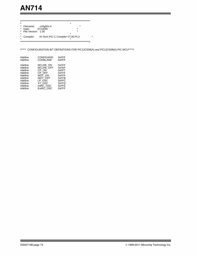
AN714
00714B.book Page 74 Friday, June 10, 2011 10:23 AM
/********************************************************************** ** Filename: cnfig50x.h ** Date: 07/18/99 ** File Version: 1.00 ** ** Compiler: Hi-Tech PIC C Compiler V7.83 PL3 ** **********************************************************************/
/***** CONFIGURATION BIT DEFINITIONS FOR PIC12C508(A) and PIC12C509(A) PIC MCU*****/
#define CONFIGADD 0xFFF#define CONBLANK 0xFFF
#define MCLRE_ON 0xFFF#define MCLRE_OFF 0xFEF#define CP_ON 0xFF7#define CP_OFF 0xFFF#define WDT_ON 0xFFF#define WDT_OFF 0xFFB#define LP_OSC 0xFFC#define XT_OSC 0xFFD#define IntRC_OSC 0xFFE#define ExtRC_OSC 0xFFF
DS00714B-page 74 © 1999-2011 Microchip Technology Inc.
AN714
00714B.book Page 75 Friday, June 10, 2011 10:23 AM
ADDITIONAL INFORMATIONMicrochip’s Secure Data Products are covered by some or all of the following: Code hopping encoder patents issued in European countries and U.S.A.Secure learning patents issued in European countries, U.S.A. and R.S.A.
REVISION HISTORY
Revision B (June 2011)• Added new section Additional Information• Minor formatting and text changes were
incorporated throughout the document
© 1999-2011 Microchip Technology Inc. DS00714B-page 75
AN714
00714B.book Page 76 Friday, June 10, 2011 10:23 AM
NOTES:
DS00714B-page 76 © 1999-2011 Microchip Technology Inc.
Note the following details of the code protection feature on Microchip devices:• Microchip products meet the specification contained in their particular Microchip Data Sheet.
• Microchip believes that its family of products is one of the most secure families of its kind on the market today, when used in the intended manner and under normal conditions.
• There are dishonest and possibly illegal methods used to breach the code protection feature. All of these methods, to our knowledge, require using the Microchip products in a manner outside the operating specifications contained in Microchip’s Data Sheets. Most likely, the person doing so is engaged in theft of intellectual property.
• Microchip is willing to work with the customer who is concerned about the integrity of their code.
• Neither Microchip nor any other semiconductor manufacturer can guarantee the security of their code. Code protection does not mean that we are guaranteeing the product as “unbreakable.”
Code protection is constantly evolving. We at Microchip are committed to continuously improving the code protection features of our products. Attempts to break Microchip’s code protection feature may be a violation of the Digital Millennium Copyright Act. If such acts allow unauthorized access to your software or other copyrighted work, you may have a right to sue for relief under that Act.
00714B.book Page 77 Friday, June 10, 2011 10:23 AM
Information contained in this publication regarding device applications and the like is provided only for your convenience and may be superseded by updates. It is your responsibility to ensure that your application meets with your specifications. MICROCHIP MAKES NO REPRESENTATIONS OR WARRANTIES OF ANY KIND WHETHER EXPRESS OR IMPLIED, WRITTEN OR ORAL, STATUTORY OR OTHERWISE, RELATED TO THE INFORMATION, INCLUDING BUT NOT LIMITED TO ITS CONDITION, QUALITY, PERFORMANCE, MERCHANTABILITY OR FITNESS FOR PURPOSE. Microchip disclaims all liability arising from this information and its use. Use of Microchip devices in life support and/or safety applications is entirely at the buyer’s risk, and the buyer agrees to defend, indemnify and hold harmless Microchip from any and all damages, claims, suits, or expenses resulting from such use. No licenses are conveyed, implicitly or otherwise, under any Microchip intellectual property rights.
© 1999-2011 Microchip Technology Inc.
Trademarks
The Microchip name and logo, the Microchip logo, dsPIC, KEELOQ, KEELOQ logo, MPLAB, PIC, PICmicro, PICSTART, PIC32 logo, rfPIC and UNI/O are registered trademarks of Microchip Technology Incorporated in the U.S.A. and other countries.
FilterLab, Hampshire, HI-TECH C, Linear Active Thermistor, MXDEV, MXLAB, SEEVAL and The Embedded Control Solutions Company are registered trademarks of Microchip Technology Incorporated in the U.S.A.
Analog-for-the-Digital Age, Application Maestro, chipKIT, chipKIT logo, CodeGuard, dsPICDEM, dsPICDEM.net, dsPICworks, dsSPEAK, ECAN, ECONOMONITOR, FanSense, HI-TIDE, In-Circuit Serial Programming, ICSP, Mindi, MiWi, MPASM, MPLAB Certified logo, MPLIB, MPLINK, mTouch, Omniscient Code Generation, PICC, PICC-18, PICDEM, PICDEM.net, PICkit, PICtail, REAL ICE, rfLAB, Select Mode, Total Endurance, TSHARC, UniWinDriver, WiperLock and ZENA are trademarks of Microchip Technology Incorporated in the U.S.A. and other countries.
SQTP is a service mark of Microchip Technology Incorporated in the U.S.A.
All other trademarks mentioned herein are property of their respective companies.
© 1999-2011, Microchip Technology Incorporated, Printed in the U.S.A., All Rights Reserved.
Printed on recycled paper.
ISBN: 978-1-61341-265-7
DS00714B-page 77
Microchip received ISO/TS-16949:2002 certification for its worldwide headquarters, design and wafer fabrication facilities in Chandler and Tempe, Arizona; Gresham, Oregon and design centers in California and India. The Company’s quality system processes and procedures are for its PIC® MCUs and dsPIC® DSCs, KEELOQ® code hopping devices, Serial EEPROMs, microperipherals, nonvolatile memory and analog products. In addition, Microchip’s quality system for the design and manufacture of development systems is ISO 9001:2000 certified.
DS00714B-page 78 © 1999-2011 Microchip Technology Inc.
AMERICASCorporate Office2355 West Chandler Blvd.Chandler, AZ 85224-6199Tel: 480-792-7200 Fax: 480-792-7277Technical Support: http://www.microchip.com/supportWeb Address: www.microchip.comAtlantaDuluth, GA Tel: 678-957-9614 Fax: 678-957-1455BostonWestborough, MA Tel: 774-760-0087 Fax: 774-760-0088ChicagoItasca, IL Tel: 630-285-0071 Fax: 630-285-0075ClevelandIndependence, OH Tel: 216-447-0464 Fax: 216-447-0643DallasAddison, TX Tel: 972-818-7423 Fax: 972-818-2924DetroitFarmington Hills, MI Tel: 248-538-2250Fax: 248-538-2260IndianapolisNoblesville, IN Tel: 317-773-8323Fax: 317-773-5453Los AngelesMission Viejo, CA Tel: 949-462-9523 Fax: 949-462-9608Santa ClaraSanta Clara, CA Tel: 408-961-6444Fax: 408-961-6445TorontoMississauga, Ontario, CanadaTel: 905-673-0699 Fax: 905-673-6509
ASIA/PACIFICAsia Pacific OfficeSuites 3707-14, 37th FloorTower 6, The GatewayHarbour City, KowloonHong KongTel: 852-2401-1200Fax: 852-2401-3431Australia - SydneyTel: 61-2-9868-6733Fax: 61-2-9868-6755China - BeijingTel: 86-10-8569-7000 Fax: 86-10-8528-2104China - ChengduTel: 86-28-8665-5511Fax: 86-28-8665-7889China - ChongqingTel: 86-23-8980-9588Fax: 86-23-8980-9500China - HangzhouTel: 86-571-2819-3180 Fax: 86-571-2819-3189China - Hong Kong SARTel: 852-2401-1200 Fax: 852-2401-3431China - NanjingTel: 86-25-8473-2460Fax: 86-25-8473-2470China - QingdaoTel: 86-532-8502-7355Fax: 86-532-8502-7205China - ShanghaiTel: 86-21-5407-5533 Fax: 86-21-5407-5066China - ShenyangTel: 86-24-2334-2829Fax: 86-24-2334-2393China - ShenzhenTel: 86-755-8203-2660 Fax: 86-755-8203-1760China - WuhanTel: 86-27-5980-5300Fax: 86-27-5980-5118China - XianTel: 86-29-8833-7252Fax: 86-29-8833-7256China - XiamenTel: 86-592-2388138 Fax: 86-592-2388130China - ZhuhaiTel: 86-756-3210040 Fax: 86-756-3210049
ASIA/PACIFICIndia - BangaloreTel: 91-80-3090-4444 Fax: 91-80-3090-4123India - New DelhiTel: 91-11-4160-8631Fax: 91-11-4160-8632India - PuneTel: 91-20-2566-1512Fax: 91-20-2566-1513Japan - YokohamaTel: 81-45-471- 6166 Fax: 81-45-471-6122Korea - DaeguTel: 82-53-744-4301Fax: 82-53-744-4302Korea - SeoulTel: 82-2-554-7200Fax: 82-2-558-5932 or 82-2-558-5934Malaysia - Kuala LumpurTel: 60-3-6201-9857Fax: 60-3-6201-9859Malaysia - PenangTel: 60-4-227-8870Fax: 60-4-227-4068Philippines - ManilaTel: 63-2-634-9065Fax: 63-2-634-9069SingaporeTel: 65-6334-8870Fax: 65-6334-8850Taiwan - Hsin ChuTel: 886-3-6578-300Fax: 886-3-6578-370Taiwan - KaohsiungTel: 886-7-213-7830Fax: 886-7-330-9305Taiwan - TaipeiTel: 886-2-2500-6610 Fax: 886-2-2508-0102Thailand - BangkokTel: 66-2-694-1351Fax: 66-2-694-1350
EUROPEAustria - WelsTel: 43-7242-2244-39Fax: 43-7242-2244-393Denmark - CopenhagenTel: 45-4450-2828 Fax: 45-4485-2829France - ParisTel: 33-1-69-53-63-20 Fax: 33-1-69-30-90-79Germany - MunichTel: 49-89-627-144-0 Fax: 49-89-627-144-44Italy - Milan Tel: 39-0331-742611 Fax: 39-0331-466781Netherlands - DrunenTel: 31-416-690399 Fax: 31-416-690340Spain - MadridTel: 34-91-708-08-90Fax: 34-91-708-08-91UK - WokinghamTel: 44-118-921-5869Fax: 44-118-921-5820
Worldwide Sales and Service
05/02/11
00714B.book Page 78 Friday, June 10, 2011 10:23 AM