Embed Size (px)
Citation preview

Wireless electricity for Implants in Body Sensor Networks
CHAPTER 1
INTRODUCTION
In recent years, wireless body sensor network (wBSN) has gained tremendous
interest in research community [1].Using this network, wireless sensors can be affixed to
the skin or the underside of clothes to perform a variety of important tasks, such as
monitoring vital signs, evaluating motor functions, and measuring physical
activity .Micro sensors may albe implanted within the body by either surgery or injection
to perform additional functions, such as restoring lost vision, hearing, and motor
functions, releasing drugs, and monitoring cancer or cardiovascular diseases.
In the military fields, a wBSN embedded within the clothes is highly
desirable since it can potentially produce warning signals of imminent attacks, detect the
presence of people or objects of interest, monitor chemicals in the air, evaluate wounds,
and communicate with a central station or an assistive device such as a rescue robot. With
the development of innovative wearable and implantable biosensors, the applications of
wBSN have been extended from physiological monitoring to everyday healthcare, as well
as fitness, sports and security. Despite the recent developments in low power sensing
devices and interface circuitry, system integration, sensor miniaturization, wireless
network communication and signal processing, the critical energy problem in wBSN has
not yet been solved.
It is a challenge to power a highly distributed network of electronic devices
without wired connections and batteries. Currently, many wBSNs use a separate battery
for each sensor node, which is obviously inconvenient, costly, and difficult to maintain.
In the case of implantable sensors, these problems become even more serious. It is highly
desirable that the implants are able to receive energy outside of the body wirelessly to
avoid the use of transcutaneous wires or the battery replacement by surgery. In 2007, a
new wireless energy transfer technology was reported in Science [2]. This technology is
often called witricitry (a short form of “wireless electricity”) which has been used to
transmit a considerably large amount of power [2-6]. For example, the original paper [2]
reported a wireless power of 60-walt which fully illuminated a light bulb approximately
two meters away from a power source with an efficiency of approximately 40%.
Department of CSE, TOCE Page 1

Wireless electricity for Implants in Body Sensor Networks
This initial experiment demonstrated the feasibility of witricity in wireless
power transfer over a “midrange”, defined as a distance equal to several times of the
resonator size. This experiment also showed that, when compared to the existing
methods, the power transfer by witricity was much less affected by the adjacent non-
resonant objects including biological tissues. Despite these advantages, the system
utilized two large coil resonators of 60 cm in diameter which were excessively large and
structurally unsuitable in practical applications,
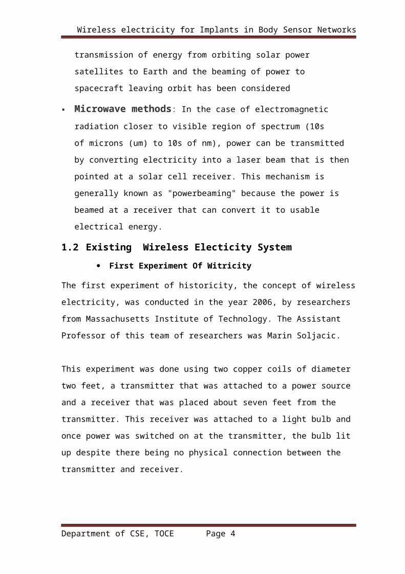
1.1 Main Challenges For Wireless Electricity
Induction methods: The electrodynamic induction wireless transmission
technique is near field over distances up to about one-sixth of the wavelength used.
Near field energy itself is non-radiative but some radiative losses do occur. In
addition there are usually resistive losses. With electrodynamic induction, electric
current flowing through a primary coil creates a magnetic field that acts on a
secondary coil producing a current within it. Coupling must be tight in order to
achieve high efficiency. As the distance from the primary is increased, more and
more of the magnetic field misses the secondary. Even over a relatively short range
the inductive coupling is grossly inefficient, wasting much of the transmitted energy.
Directed radio waves: Power transmission via radio waves can be made more
directional, allowing longer distance power beaming, with shorter wavelengths of
electromagnetic radiation, typically in the microwave range. A rectenna may be used
to convert the microwave energy back into electricity. Rectenna conversion
efficiencies exceeding 95% have been realized. Power beaming using microwaves
has been proposed for the transmission of energy from orbiting solar power
satellites to Earth and the beaming of power to spacecraft leaving orbit has been
considered
Microwave methods: In the case of electromagnetic radiation closer to visible
region of spectrum (10s of microns (um) to 10s of nm), power can be transmitted by
converting electricity into a laser beam that is then pointed at a solar cell receiver.
This mechanism is generally known as "powerbeaming" because the power is beamed
at a receiver that can convert it to usable electrical energy.
Department of CSE, TOCE Page 2
Wireless electricity for Implants in Body Sensor Networks
1.2 Existing Wireless Electicity System First Experiment Of Witricity
The first experiment of historicity, the concept of wireless electricity, was conducted in
the year 2006, by researchers from Massachusetts Institute of Technology. The Assistant
Professor of this team of researchers was Marin Soljacic.
This experiment was done using two copper coils of diameter two feet, a transmitter
that was attached to a power source and a receiver that was placed about seven feet
from the transmitter. This receiver was attached to a light bulb and once power was
switched on at the transmitter, the bulb lit up despite there being no physical
connection between the transmitter and receiver.
The MIT researchers have been able to power a 60 watt light bulb from a power source
that is located about seven feet away, while providing forty percent efficiency. This was
made possible using two copper coils that were twenty inches in diameter which were
designed so that they resonated together in the MHz range. One of these coils were
connected to a power source while the other, to a bulb. With this witricity setup, the bulb
got powered even when the coils were not in sight.
Data collected through measurements showed that there was transference of 40% of
electricity through witricity. The interesting part of the electricity was that the bulb
glowed despite the fact that wood, metal and other devices were placed in between the
two coils.
This concept of witricity was made possible using resonance where an object vibrates
with the application of a certain frequency of energy. So two objects having similar
resonance tend to exchange energy without causing any effects on the surrounding
objects. Just like in acoustic resonance, where there is a chance of a glass breaking if you
strike the right tone, witricity is made possible with the resonance of low frequency
electromagnetic waves.
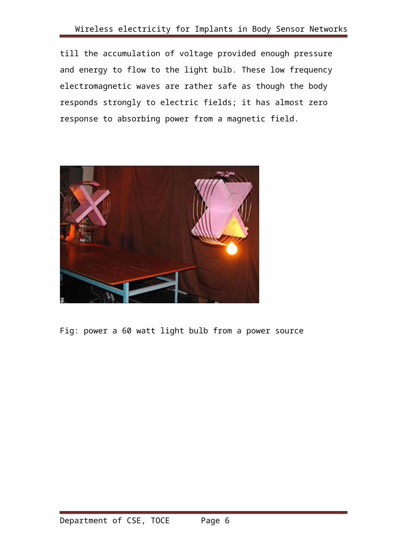
In this experiment, the coils were resonated at 10 MHz where the cols coupled and energy
Department of CSE, TOCE Page 3
Wireless electricity for Implants in Body Sensor Networks
made to flow between them. With each cycle, more pressure and voltage built up in the
coil till the accumulation of voltage provided enough pressure and energy to flow to the
light bulb. These low frequency electromagnetic waves are rather safe as though the body
responds strongly to electric fields; it has almost zero response to absorbing power from a
magnetic field.
Fig: power a 60 watt light bulb from a power source
Department of CSE, TOCE Page 4

Wireless electricity for Implants in Body Sensor Networks
The main objective of this research is to achieve resilience by adding two new,
real time data mining-based layers to complement the two existing non-data mining
layers. These new layers will improve detection of fraudulent applications because the
detection system can detect more types of attacks, better account for changing legal
behaviour, and remove the redundant attributes.
These new layers are not human resource intensive. They represent patterns in a
score where the higher the score for an application, the higher the suspicion of fraud (or
anomaly). In this way, only the highest scores require human intervention. These two new
layers do not use external databases, but only the credit application database. And
crucially, these two layers are unsupervised algorithms which are not completely
dependent on known frauds but use them only for evaluation.
The main contribution of this paper is the demonstration of resilience, with
adaptivity and quality data in real-time data mining-based detection algorithms. The
second contribution is the significant extension of knowledge in credit application fraud
detection because publications in this area are rare. In addition, this research uses the key
ideas from other related domains to design the credit application fraud detection
algorithms. Finally, the last contribution is the recommendation of credit application
fraud detection as one of the many solutions to identity crime. Being at the first stage of
the credit life cycle, credit application fraud detection also prevents some credit
transactional fraud.
Department of CSE, TOCE Page 5
Wireless electricity for Implants in Body Sensor Networks
CHAPTER 2
RELATED WORK
2.1 Developments Made So Far
As witricity is in the developmental stage, lots of work is still to be done in improving
it as it is disclosed that witricity power applications operate at only 40% efficiency.
However, Intel reproduced the MIT group's experiment by wirelessly powering a
light bulb with 75% efficiency at a shorter distance.
Just as beneficial witricity may be, there are some contraindications to the concept,
with debates if it is risky living next to power lines and having a low power witricity
network running in the home. They wonder what happens if a glass of water is spilt in
a witricity room. This has also been achieved.It is realized that instead of irradiating
the environment with electromagnetic waves, a power transmitter could fill the space
around it with a "non-radiative" electromagnetic field. Essentially, energy would only
be picked up by gadgets specified to "resonate" with the frequency.
However despite these contraindications, witricity has a bright future with the many
advantages it provides in terms of weight, convenience and portability of electrical
appliances
Department of CSE, TOCE Page 6

Wireless electricity for Implants in Body Sensor Networks
CHAPTER 3
PROPOSED METHODS
3.1 Understanding Witricity Based On Coupled Mode Theory
Fig:3.1 Basic components of Witricity system
As shown in Fig. 1, the witricity system consists of
tworesonators (labeled as “Source” and “Device”), a driving loop, and an output loop.
The source resonator is coupled inductively with the driving loop which is linked to an
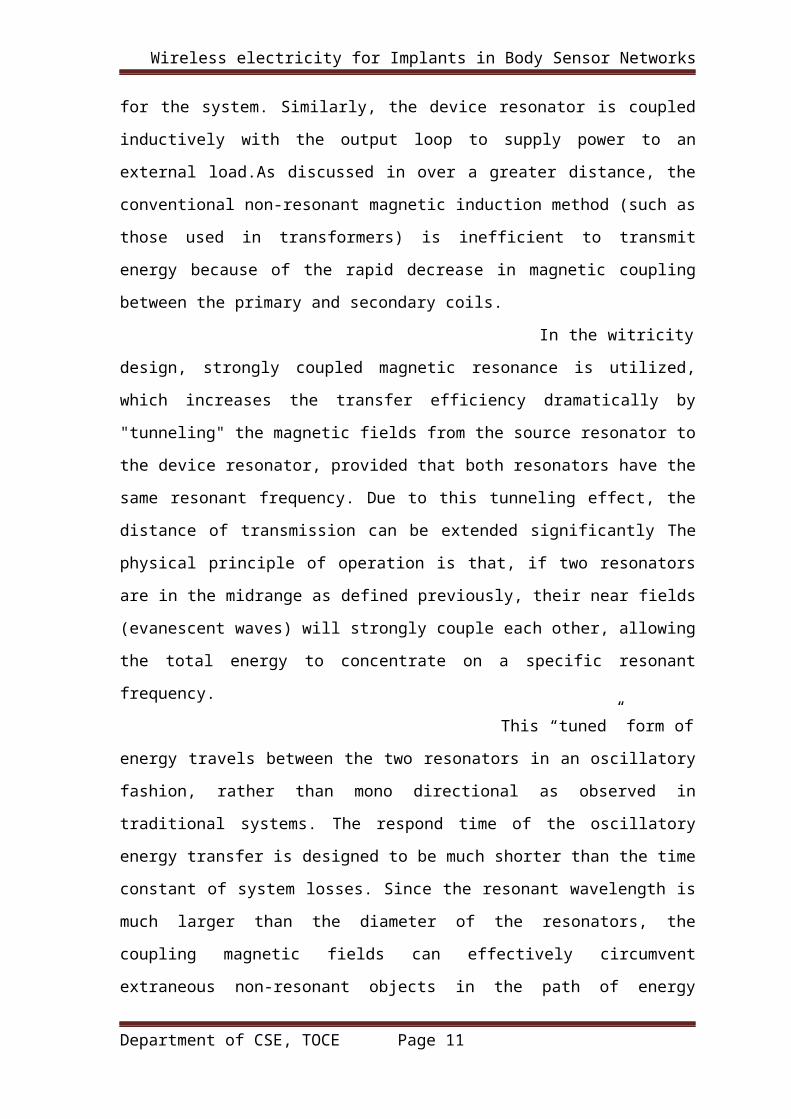
oscillator to obtain the energy for the system. Similarly, the device resonator is coupled
inductively with the output loop to supply power to an external load.As discussed in over
a greater distance, the conventional non-resonant magnetic induction method (such as
those used in transformers) is inefficient to transmit energy because of the rapid decrease
in magnetic coupling between the primary and secondary coils.
In the witricity design, strongly coupled magnetic resonance is
utilized, which increases the transfer efficiency dramatically by "tunneling" the magnetic
fields from the source resonator to the device resonator, provided that both resonators
have the same resonant frequency. Due to this tunneling effect, the distance of
transmission can be extended significantly The physical principle of operation is that, if
two resonators are in the midrange as defined previously, their near fields (evanescent
Department of CSE, TOCE Page 7

Wireless electricity for Implants in Body Sensor Networks
waves) will strongly couple each other, allowing the total energy to concentrate on a
specific resonant frequency.
This “tuned” form of energy travels between the two resonators in
an oscillatory fashion, rather than mono directional as observed in traditional systems.
The respond time of the oscillatory energy transfer is designed to be much shorter than
the time constant of system losses. Since the resonant wavelength is much larger than the
diameter of the resonators, the coupling magnetic fields can effectively circumvent
extraneous non-resonant objects in the path of energy transfer. Therefore, this midrange
energy-transfer scheme does not impose the “lineof- sight” condition, which is highly
desirable in many practical applications. Under the same energy transmitted from a
distance, the witricity system can be more safely implemented than electromagnetic
energy transfer systems because the witricity system can be designed to use the magnetic
field in energy transfer and this type of field interacts weakly with living organisms.
3.2 Evanescent Wave Coupling (EWC) Or non-radiative energy transfer, introduces a concept called “resonance” to the wireless energy equation. Similar to mutual induction, wherein electricity traveling along an electromagnetic wave moves between coils on the same frequency, EWC functions on the concept that if you make both coils resonate at the same frequency, electricity can be passed between them at farther distances and without health dangers. According to this theory, one can even send electricity to multiple devices at once, as long as they all share the same resonance frequency. While this technology is yet to come to market, in 2007, researchers at MIT published a detailed report describing a working prototype they had built which powered a light bulb from two metres away.
Department of CSE, TOCE Page 8

Wireless electricity for Implants in Body Sensor Networks
Fig:3.2 A depiction of how Evanescent Wave Coupling would work.
Department of CSE, TOCE Page 9

Wireless electricity for Implants in Body Sensor Networks
CHAPTER 4
EXPERIMENTAL RESULTS
4.1 Resonators Energy Calculation:
The simple formalism for the temporal dynamic of a resonant mode is particularly well
suited for the description of coupling between two witricity resonators. Considering the
equations of motion of the amplitudes a1( t) anda2 ( t) of two coupled lossless resonators
with natural frequencies
Where 12 k and 21 k are the coupling coefficients between two modes and can be treated
as complex numbers rather than operators. According to the law of energy conservation,
a restriction on 12 k and 21 k should be imposed. In then extreme case where no energy
loss is assumed, the time rate of energy change must vanish, given by
Since a1(t) and a2(t) can have arbitrary initial amplitudes and phases, the coupling
coefficients satisfy
Solving for the natural frequencies of the coupled systems, we can obtain two
homogeneous equations in the amplitudes and a1(t) and a2(t) from (1) and (2).
Department of CSE, TOCE Page 10
Wireless electricity for Implants in Body Sensor Networks
Equation (7) indicates that the two frequencies of the coupled system are separated by
In particular, when , the difference between the two natural
frequencies of the coupled modes is
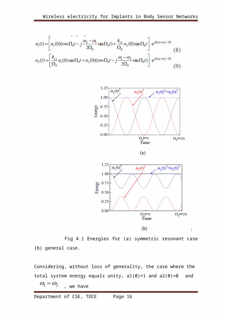
Suppose, initially, that at a1(t) and a2(t) are specified. Then, the two solutions of
equations (1) and (2) are expressed.
Department of CSE, TOCE Page 11

Wireless electricity for Implants in Body Sensor Networks
:
Fig 4.1 Energies for (a) symmetric resonant case (b) general case.
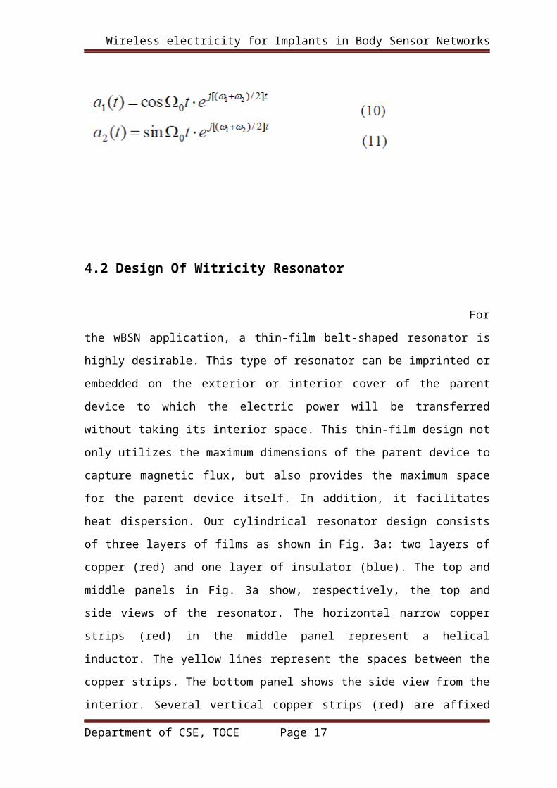
Considering, without loss of generality, the case where the
total system energy equals unity, a1(0)=1 and a2(0)=0 and
, we have
4.2 Design Of Witricity Resonator
Department of CSE, TOCE Page 12

Wireless electricity for Implants in Body Sensor Networks
For the wBSN application, a thin-film belt-shaped
resonator is highly desirable. This type of resonator can be imprinted or embedded on the
exterior or interior cover of the parent device to which the electric power will be
transferred without taking its interior space. This thin-film design not only utilizes the
maximum dimensions of the parent device to capture magnetic flux, but also provides the
maximum space for the parent device itself. In addition, it facilitates heat dispersion. Our
cylindrical resonator design consists of three layers of films as shown in Fig. 3a: two
layers of copper (red) and one layer of insulator (blue). The top and middle panels in Fig.
3a show, respectively, the top and side views of the resonator. The horizontal narrow
copper strips (red) in the middle panel represent a helical inductor. The yellow lines
represent the spaces between the copper strips. The bottom panel shows the side view
from the interior. Several vertical copper strips (red) are affixed to the insulator film
(blue). These vertical strips form physical capacitors with the coil conductors in the
exterior layer. Clearly, this thin-film design represents a compact LC tank circuit.
In our design, energy transfer is primarily provided
by the magnetic field, while the electric field is mostly confined within the physical
capacitors. This feature effectively prevents the leakage of the electrical field and helps
reduce health concerns since the biological tissue (and other electrically conductive
objects) interacts much more strongly with electric fields than with magnetic fields.
Another motivation of our design is to obtain a compact size. By increasing the
capacitance using the strips while keeping the same inductance in the LC tank resonator,
the operating frequency of the witricity system can be reduced, which is desirable in
many practical applications where the size of the parent device is small. In practical
applications, the size and shape of the source resonator have fewer restrictions and can be
larger than that of the device resonator.
Department of CSE, TOCE Page 13

Wireless electricity for Implants in Body Sensor Networks
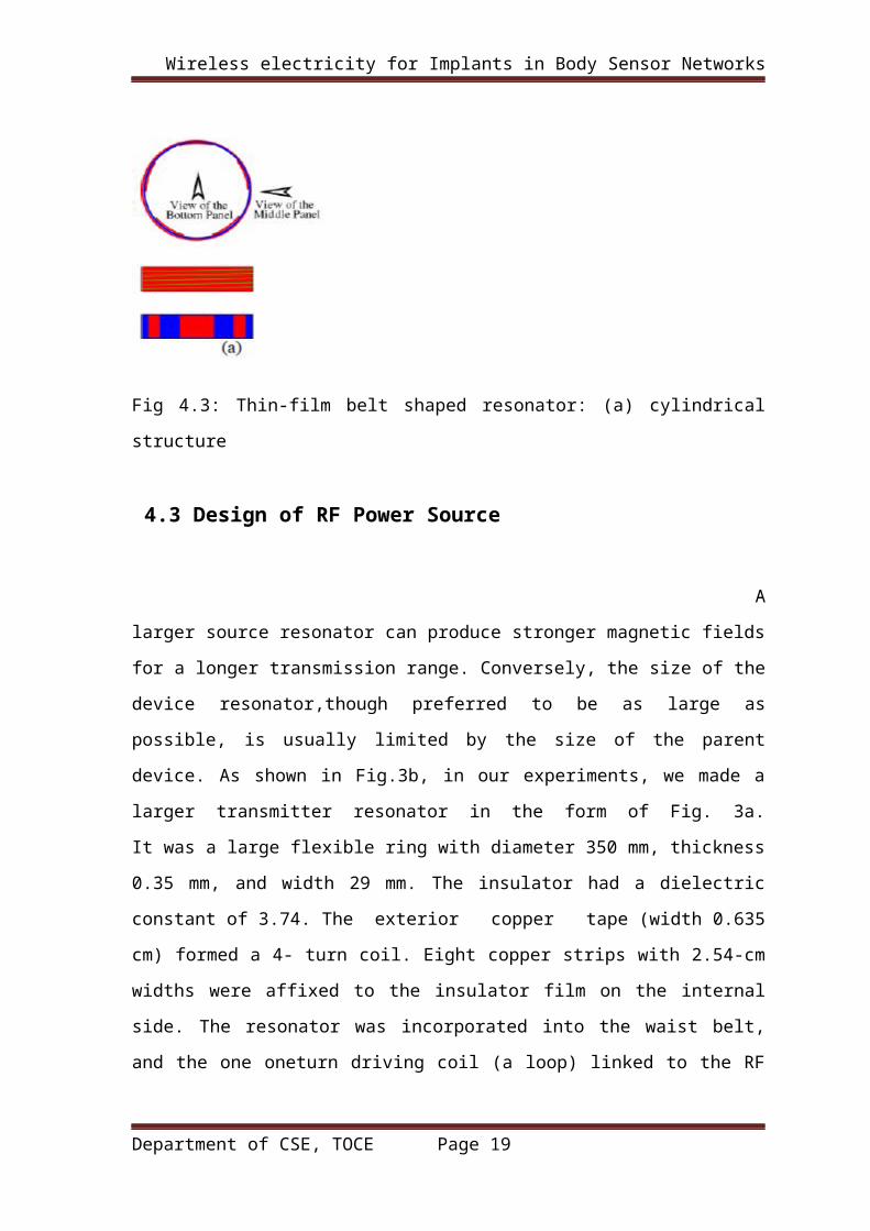
Fig 4.3: Thin-film belt shaped resonator: (a) cylindrical structure
4.3 Design of RF Power Source
A larger source resonator can produce stronger magnetic
fields for a longer transmission range. Conversely, the size of the device resonator,though
preferred to be as large as possible, is usually limited by the size of the parent device. As
shown in Fig.3b, in our experiments, we made a larger transmitter resonator in the form
of Fig. 3a. It was a large flexible ring with diameter 350 mm, thickness 0.35 mm, and
width 29 mm. The insulator had a dielectric constant of 3.74. The exterior copper tape
(width 0.635 cm) formed a 4- turn coil. Eight copper strips with 2.54-cm widths were
affixed to the insulator film on the internal side. The resonator was incorporated into the
waist belt, and the one oneturn driving coil (a loop) linked to the RF power source can
was attached on the belt to make the system wearable.
Using vector network analyzer (8753ES), we set its resonant
frequency to be 7 MHz and Q value was measured to be51.62, which was likely lower
than its true value because aprecise Q measurement was difficult without expensive
equipment and the error was expected to be large. Likewise, based on the design in Fig.
3a, a smaller receiver resonator was made as shown in Fig. 3c. The exterior copper strip
with 0.635-cm width formed a 6-turn coil, and six copper strips with 2.54-cm widths were
affixed to the insulator film on the internal side. The radius and height of the cell were
about 8.1 cm and 5 cm, respectively. Similarly, we also designed much smaller resonator
for other body part such as arm. A seven-turn coil was used as the output coil to connect
and power the load. We also set its resonant frequency to be 7 MHz and measured its Q
Department of CSE, TOCE Page 14

Wireless electricity for Implants in Body Sensor Networks
value as 56.38. For the purpose of observation, an LED was first used as the load,
simulating the load effect of electronics devices and allowing visual examination.
This LED was then replaced by a resister from which
quantitative measurements was performed. In order to satisfy the requirement of
commonly usedn electronics devices, we also believe the planar structure will be
desirable since it will be easily implemented by printing this resonator on the internal or
external cover, or embedded in the clothes. Similarly with above cylindrical structures, as
shown in Fig.3d and 3e, a planar thin-film receiver resonator
is also designed. It includes three layers: the top metal layer formed a planar spiral
rectangular coil by attaching the metal strip on an insulated thin film (middle layer,
transparent), underneath which there are several separated vertical metal strips. The top
metal strip and bottom metal strips can form capacitors, resulting in a compact LC tank
resonator. Due to page limitation, we will focus on the cylindrical structure.
Fig 4.3: Thin-film belt shaped resonator: (b)transmitter resonator; (c) receiver resonator;
(d) and (e) planar resonator
4.4 Experimental Results
Department of CSE, TOCE Page 15
Wireless electricity for Implants in Body Sensor Networks
Fig. 4.3 shows an experimental 7 MHz witricity system on a workbench.
Wireless energy fully illuminated the LED. When we misaligned the axes of
source and device resonators, the power was still be transmitted efficiently as
shown in Fig.4b. This phenomenon differs from that of the conventional
magnetic induction methods. In order to evaluate system performance
quantitatively, we replaced the LED with a resistor whose resistance
approximates the impedance of the output terminals at resonance. Utilizing a
diode-based RF detector, we measured the RF energy at the input terminals
of the driving loop and the energy at the loadterminals of the output loop.
Department of CSE, TOCE Page 16
Wireless electricity for Implants in Body Sensor Networks
Fig 4.3(a) Measured transmission efficiency vs. distances of separation
Then the power transfer efficiencies with and
without misalignment are measured and plotted in Fig.5. It can be seen that,
the efficiency without misalignment can reach approximately 80 % at a 15-
cm separation between the transmitter and receiver. It can also be seen that
certain misalignments (e.g. 5 cm) between transmitter and receiver cause
only a slight drop in efficiency. This tolerance in misalignment is highly
desirable in practical applications since, for example, it allows energy to be
transmitted to a moving target or multiple locations as in the case of wBSN.
As [2, 3], we also arrived at the same conclusion that the uninterruptible line
of- sight between the transmitter and receiver is unnecessary in the witricity
system. Also in [9], we reported a relay effect of witricity, which allows a
much longer effective transmission distance with one or more relay resonator
between source and device resonators. Obviously, this physical mechanism
will further enhance the robustness of
Department of CSE, TOCE Page 17

Wireless electricity for Implants in Body Sensor Networks
CHAPTER 5
CONCLUSION
As a new method of wireless energy transfer, witricity has a high potential in medical
applications. In this paper, we investigate the feasibility of witricity in providing wireless
power to body sensor networks. A theoretical analysis has been presented to understand
the oscillatory behavior in system operation. A novel type of thin film belt-shaped
resonators has been designed, fabricated and measured. A witricity prototype system was
built and evaluated. Our experimental results have indicated that the witricity technology
provides a powerful solution to power multiple sensors in wireless body sensor networks
REFERENCES
Department of CSE, TOCE Page 18
Wireless electricity for Implants in Body Sensor Networks
[1] G.Z. Yang, “Body sensor networks”, Birkhauser, 2006, ISBN: 978-1- 84628-272-0
[2] A. Kurs, A. Karalis, R. Moffatt, J. D. Joannopoulos, P. Fisher, and M. Soljacic,
“Wireless Power Transfer via Strongly Coupled Magnetic Resonances”, Science, Vol.
317, pp. 83-86, Jul. 2007.
[3] A. Karalis, J.D. Joannopoulos, and M. Soljacic, “Efficient Wireless Non-radiative
Mid-range Energy Transfer”, Annals of Physics, Vol. 323, pp. 34-48, Jan. 2008.
[4] V. Chrisianto and F. Smarandache, “A note on Computer Solution of Wireless
Energy Transmit via Magnetic Resonance”, Process in Physics, Vol. 1, pp.81 83, Jan.
2008.
[5] Y. Hori, “Motion Control of Electric Vehicles and Prospects of supercapacitors”,
IEEJ Transactions on Electrical and Electronic Engineering, Vol.4, pp.231-239, Feb.
2009.
[6] A. Kurs, R. Moffatt, and M. Soljacic, “Simultaneous mid-range power transfer to
multiple devices”, Applied Physics Letters, Vol.96, pp.044102, Jan. 2010
[7] F. Zhang, S. A. Hackworth, X. Liu, H. Chen, R. J. Sclabassi, and M. Sun, “Wireless
Energy Transfer Platform for Medical Sensors and Implantable Devices”, IEEE
International Conf. of EMBS, Minneapolis, Minnesota, USA, Sep. 2-6, 2009.
[8] F. Zhang, X. Liu, S. A. Hackworth, R. J. Sclabassi, and M. Sun, “In Vitro and In
Vivo Studies on Wireless Powering of Medical Sensors and Implantable Devices,” Fourth
annual IEEE-NIH Life Science Systems and Application, Bethesda, Maryland, USA, Apr
9-10, 2009.
[9] F. Zhang, S. A. Hackworth, W. Fu and M. Sun, “The Relay Effect on Wireless Power
Transfer Using Witricity”, 14th Biennial IEEE Conference on Electromagnetic Field
Computation, Chicago Illinois, USA, May 9-12, 2010.
[10] H. Haus, Waves and Fields in Optoelectronics, Chapter 7, Prenticehall, Englewood
Cliffs, NJ,1984
Department of CSE, TOCE Page 19