Embed Size (px)
Citation preview
8/13/2019 Wireless Data Transmission SAE
http://slidepdf.com/reader/full/wireless-data-transmission-sae 1/8
Rio de Janeiro, BrasilJune, 13 th - 14th
AV. PAULISTA, 2073 - HORSA II - CJ. 1003 - CEP 01311-940 - SÃO PAULO – SP
SAE TECHNICAL 2013-36-0064 PAPER SERIES E
The Design Process of a Wireless Data Transmission System
Paulo Bosquiero ZanettiFormula UFSC Team, Federal University of Santa Catarina
Applied to a Formula SAE Vehicle
AFFILIATED TO
Downloaded from SAE International by Brought to you by RMIT University, Sunday, December 29, 2013 06:08:19 AM
8/13/2019 Wireless Data Transmission SAE
http://slidepdf.com/reader/full/wireless-data-transmission-sae 2/8
The appearance of the ISSN code at the bottom of this page indicates SAE’sconsent that copies of the paper may be made for personal or internal use ofspecific clients. This consent is given on the condition however, that the copier pay a$ 7.00 per article copy fee through the Copyright Clearance Center, Inc. OperationsCenter, 222 Rosewood Drive, Danvers, MA 01923 for copying beyond that permittedby Sections 107 or 108 of U.S. Copyright Law. This consent does not extend toother kinds of copying such as copying for general distribution, for advertising orpromotional purposes, for creating new collective works, or for resale.
SAE routinely stocks printed papers for a period of three years following date ofpublication. Direct your orders to SAE Customer Sales and Satisfaction Department.
Quantity reprint rates can be obtained from the Customer Sales and SatisfactionDepartment.
To request permission to reprint a technical paper or permission to use copyrightedSAE publications in other works, contact the SAE Publications Group.
All SAE papers, standards, and selectedbooks are abstracted and indexed in theGlobal Mobility Database.
No part of this publication may be reproduced in any form, in an electronic retrievalsystem or otherwise, without the prior written permission of the publisher.
ISSN 0148-7191Copyright © 2013 SAE Interna tiona l
Positions and opinions advanced in this paper are those of the author(s) and notnecessarily those of SAE. The author is solely responsible for the content of thepaper. A process is available by which discussions will be printed with the paper if itis published in SAE Transactions. For permission to publish this paper in full or inpart, contact the SAE Publications Group.
Persons wishing to submit papers to be considered for presentation or publication through SAEshould send the manuscript or a 300 word abstract of a proposed manuscript to: Secretary,
Engineering Meetings Board, SAE.
Downloaded from SAE International by Brought to you by RMIT University, Sunday, December 29, 2013 06:08:19 AM
8/13/2019 Wireless Data Transmission SAE
http://slidepdf.com/reader/full/wireless-data-transmission-sae 3/8
Page 1 of 6
2013-36-0064
The Design Process of a Wireless Data Transmission System Applied
Paulo Bosquiero ZanettiFormula UFSC Team, Federal University of Santa Catarina
Copyright © 2013 SAE International
ABSTRACT
Data analysis is an important way to validate and optimizeengineering’s designs. With the development of wirelesstransmission systems, race cars use telemetry as a solution tomeasure the car’s behavior by the analysis of acquired data.Wireless communication systems provide the possibility toanalyze data in real-time situations, allowing tactical decisionmaking based on the vehicle’s embedded signalsinterpretation.
This paper intends to describe the design process of a wirelessdata transmission system applied to a Formula SAE vehicle.Based on the prototyping microcontroller Arduino ™ and theradio-transmission module Xbee®, the wireless transmissionsystem here described is capable of transmitting 16 analog and54 digital embedded signals and can be easily adapted for theuser’s requirements, through the system’s open -sourcecharacteristics.
INTRODUCTION
MOTOR RACING TELEMETRYSYSTEMS
Through the advance of wireless and signal processingsystems, the industry is now able to monitor processes withmuch accuracy and speed. Telemetry can be defined as theidea of transmitting and receiving data through wirelesscommunication technologies [1], and is, nowadays, applied inevery industry niche.
In this paper, telemetry will be considered as a tool for motorracing sports, allowing designs validation, adjustments ofmechanical and electrical components, and tactical decisions
trough real-time data analysis. Telemetry provides the non- physical connection between the used transducers, and thecontrol unit. This characteristic of wireless communicationsystems allows the monitoring of moving systems, such as arace car.
FORMULA SAE CATEGORY
The Formula SAE [9] is a student design competitionorganized by the Society of Automotive Engineers (SAE)[10], where students have to design and build an open wheeledrace car, to dispute a competition against other student’steams.
Inside the product design process, the teams have to test eachsolution that was proposed, as the behavior of the car can beimproved. In this way, a low cost open source wireless datatransmission system, capable to collect and supply the desiredamount of data in real time situations will become a useful andimportant instrument.
This paper intends to describe the design process of a simpleand reliable wireless data transmission system, based on theopen source concept, which allows the Formula SAE teams tomodify the current system in order to use different types ofsensors installed on the vehicle, conceding the possibility toadapt the wireless system to any design requirement.
OPEN SOURCE CONCEPT
The open source concept can be defined as a methodologywhich allows the access to a product’s design andimplementation details [3] This characteristic is sought byFormula SAE teams in order to undervalue the system throughthe possibility of change and adaptation of the system to theteam’s requirements , without the need of hardware change.
to a Formula SAE Vehicle
Downloaded from SAE International by Brought to you by RMIT University, Sunday, December 29, 2013 06:08:19 AM
8/13/2019 Wireless Data Transmission SAE
http://slidepdf.com/reader/full/wireless-data-transmission-sae 4/8
Page 2 of 6
SYSTEMS DEVELOPMENT
HARDWARE
The wireless data transmission system described consists basically in two components, the Arduino prototyping board,responsible for processing the acquired data and the Zigbeeradio-frequency module, Xbee [1], [4].
The Arduino Mega 2560 board [1], [2] is the open-source prototyping platform chosen for the data transmission system.It is based on the Atmega2560 microcontroller and has a 10
bits A/D converter for the 16 analog inputs and has its own programming language, similar to C/C++. The signalsacquired by the transducers installed on the car are applied tothe Arduino inputs and from there, are processed by themicrocontroller, communicating itself directly andinstantaneously with the Zigbee module.
Zigbee is a wireless communication specification for low power electronic devices, based on the IEEE 802.15.4 [7], [8]standard. It allows bidirectional communication between small
digital radios for personal area networks (PAN) [8]. The Xbeemodules of the wireless communication system described inthis paper, work as a point to point communication bridge.The transmitter sends the acquired data processed by themicrocontroller to the receiver module, which is connected toan Ultra Serial Bus (USB) port to a computer that displays thedata through a graphic interface.
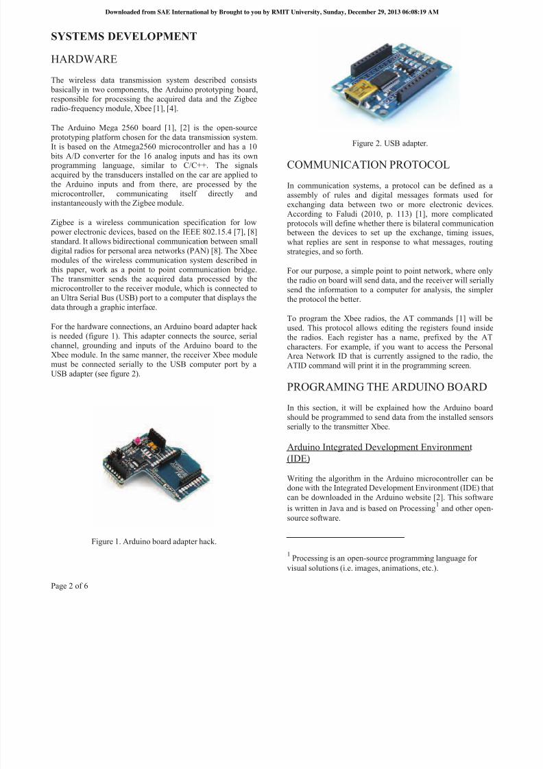
For the hardware connections, an Arduino board adapter hackis needed (figure 1). This adapter connects the source, serialchannel, grounding and inputs of the Arduino board to theXbee module. In the same manner, the receiver Xbee modulemust be connected serially to the USB computer port by a
USB adapter (see figure 2).
Figure 1. Arduino board adapter hack.
Figure 2. USB adapter.
COMMUNICATION PROTOCOL
In communication systems, a protocol can be defined as aassembly of rules and digital messages formats used forexchanging data between two or more electronic devices.According to Faludi (2010, p. 113) [1], more complicated
protocols will define whether there is bilateral communication between the devices to set up the exchange, timing issues,what replies are sent in response to what messages, routingstrategies, and so forth.
For our purpose, a simple point to point network, where onlythe radio on board will send data, and the receiver will seriallysend the information to a computer for analysis, the simplerthe protocol the better.
To program the Xbee radios, the AT commands [1] will beused. This protocol allows editing the registers found insidethe radios. Each register has a name, prefixed by the ATcharacters. For example, if you want to access the PersonalArea Network ID that is currently assigned to the radio, theATID command will print it in the programming screen.
PROGRAMING THE ARDUINO BOARD
In this section, it will be explained how the Arduino boardshould be programmed to send data from the installed sensorsserially to the transmitter Xbee.
Arduino Integrated Development Environment(IDE)
Writing the algorithm in the Arduino microcontroller can bedone with the Integrated Development Environment (IDE) that
can be downloaded in the Arduino website [2]. This softwareis written in Java and is based on Processing 1 and other open-source software.
1 Processing is an open-source programming language forvisual solutions (i.e. images, animations, etc.).
Downloaded from SAE International by Brought to you by RMIT University, Sunday, December 29, 2013 06:08:19 AM
8/13/2019 Wireless Data Transmission SAE
http://slidepdf.com/reader/full/wireless-data-transmission-sae 5/8
Page 3 of 6
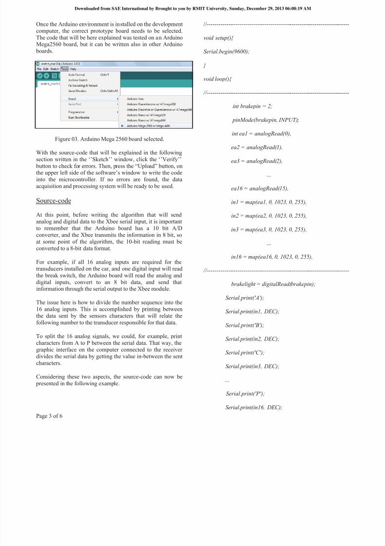
Once the Arduino environment is installed on the developmentcomputer, the correct prototype board needs to be selected.The code that will be here explained was tested on an ArduinoMega2560 board, but it can be written also in other Arduino
boards.
Figure 03. Arduino Mega 2560 board selected.
With the source-code that will be explained in the followingsection written in the ‘’Sketch’’ window, click the ‘’Verify’’
button to check for errors. Then, press the “Upload” button, onthe upper lef t side of the software’s window to write the codeinto the microcontroller. If no errors are found, the dataacquisition and processing system will be ready to be used.
Source-code
At this point, before writing the algorithm that will sendanalog and digital data to the Xbee serial input, it is importantto remember that the Arduino board has a 10 bit A/Dconverter, and the Xbee transmits the information in 8 bit, soat some point of the algorithm, the 10-bit reading must beconverted to a 8-bit data format.
For example, if all 16 analog inputs are required for thetransducers installed on the car, and one digital input will readthe break switch, the Arduino board will read the analog anddigital inputs, convert to an 8 bit data, and send thatinformation through the serial output to the Xbee module.
The issue here is how to divide the number sequence into the16 analog inputs. This is accomplished by printing betweenthe data sent by the sensors characters that will relate thefollowing number to the transducer responsible for that data.
To split the 16 analog signals, we could, for example, printcharacters from A to P between the serial data. That way, thegraphic interface on the computer connected to the receiverdivides the serial data by getting the value in-between the sentcharacters.
Considering these two aspects, the source-code can now be presented in the following example.
//--------------------------------------------------------------------------
void setup(){
Serial.begin(9600);
}
void loop(){
//--------------------------------------------------------------------------
int brakepin = 2;
pinMode(brakepin, INPUT);
int ea1 = analogRead(0),
ea2 = analogRead(1),
ea3 = analogRead(2),
…
ea16 = analogRead(15),
in1 = map(ea1, 0, 1023, 0, 255),
in2 = map(ea2, 0, 1023, 0, 255),
in3 = map(ea3, 0, 1023, 0, 255),
…
in16 = map(ea16, 0, 1023, 0, 255),
//--------------------------------------------------------------------------
brakelight = digitalRead(brakepin);
Serial.print('A');
Serial.print(in1, DEC);
Serial.print('B');
Serial.print(in2, DEC);
Serial.print('C');
Serial.print(in3, DEC);
…
Serial.print('P');
Serial.print(in16, DEC);
Downloaded from SAE International by Brought to you by RMIT University, Sunday, December 29, 2013 06:08:19 AM
8/13/2019 Wireless Data Transmission SAE
http://slidepdf.com/reader/full/wireless-data-transmission-sae 6/8
Page 4 of 6
Serial.print('Q');
Serial.print(brakelight);
delay(2);
}
//--------------------------------------------------------------------------
The first section of the code initializes the routine, sets the baud rate of 9600 bits per second for the microcontroller andopens the loop for the data reading.
To define the variables of each sensor value, and remap from a10 bit to a 8 bit data format, the second section of the codeuses the analogRead() and map() functions. These functionsare also described in the Arduino website.
Finally, the third section sends the acquired signals alternatelywith the chosen characters to the serial output pin. After it, thedelay function waits two milliseconds before repeating theroutine, providing a 500 Hz sample rate. The delay time willdefine the sample rate of the system, and it must be calculatedfrom the higher frequency read, according to the Nyquist-Shannon sample theorem [6] 2.
PROGRAMING THE XBEE RADIODEVICES
Coordinator and Router
With the purpose of programming the two Xbee modules, aserial terminal program is fundamental. This kind of softwareallows the user to update and change the current firmwarewritten in the internal Xbee microcontroller. Also, through theserial terminal program, we can program the module by typingAT commands previously introduced. This way, it is possibleto configure the radio modules to communicate just to eachother, by writing its ID number from one to the other. This
process will be described with more details later.
The chosen serial terminal program is the X-CTU, developed by Digi, the same manufacturer as the Xbee modules. It can befreely downloaded from the Digi website [5]
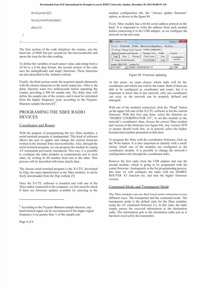
Once the X-CTU software is installed and with one of theXbee radios connected to the computer, we first need do checkif there are firmware updates available by selecting in the
2 According to the Nyquist-Shannon sample theorem, any band limited signal can be reconstructed if the higher signalfrequency is no greater than ½ of the sample rate
modem configuration tab, the “Always update firmware”option, as shown in the figure 04.
Every Xbee module has a 64-bit serial address printed on the back. It is important to write the address from each module before connecting it to the USB adapter, so we configure thenetwork on the next step.
Figure 04. Firmware updating.
At this point, we must choose which radio will be thecoordinator and which one will be the router. Both of them areable to be configured as coordinator and router, but it isimportant to know that in any network, only one coordinatorcan exist, so the network can be properly defined andmanaged.
With one of the modules connected, click the “Read” buttonon the upper left side of the X-CTU software to list the currentfirmware. With this first step done, select the function set“ZIGBEE COORDINATOR AT”, to set this module as thenetwork’s coordinator, than, ch oose the correct Xbee modemand version of the firmware (see figure 04). Any version 2070or greater should work fine, so in general, select the higherhexadecimal number presented on that item.
To program the Xbee with the coordinator firmware, click onthe Write button. It is also important to identify with a smallsticker which one of the modules are configured as thecoordinator module. It is possible to change the network’sconfiguration only through the coordinator radio.
Remove the first radio from the USB adapter and seat thesecond module, which is going to be programed with therouter firmware. Analogously to the fist programming process,this time we will configure the radio with the ZIGBEEROUTER AT function set, and also the higher firmwareversion.
Command Mode and Transparent Mode
The Xbee modules can use their local serial connection in twodifferent ways: The transparent and the command mode. Thetransparent mode is the default state for the Xbee modulesusing the AT command firmware [1]. In this state, the radiosimply passes the received information to the destinationradio. The information gets to the destination radio just as ithas been received by the transmitter.
Downloaded from SAE International by Brought to you by RMIT University, Sunday, December 29, 2013 06:08:19 AM

8/13/2019 Wireless Data Transmission SAE
http://slidepdf.com/reader/full/wireless-data-transmission-sae 7/8
Page 5 of 6
The command mode is used to stop the communication for amoment, to access the configuration of the local radio. In thiscase, the user wants to communicate to the radio, and not tosend the information through the Xbee module [1]. To set theradio in command mode, the user has to wait one second, type+++ and wait another second, in the X-CTU terminal tab.
After typing +++ , the software will respond “OK”, meaningthat the command mode has been activated, and will beactivated for 10 seconds before dropping out the commandmode, getting in transparent mode and starts sending orreceiving data again.
AT Commands
In this section, it will be briefly explained some of the mostcommon and important AT commands. Those commands will
be used later, when we start programing the Xbee radios.
ATID
With the radio on command mode, typing ATID by itself will
show the Personal Area Network (PAN) ID assigned to themodule. This hexadecimal number defines the network thatthe module will join to. To assign a new PAN ID number, typethe ATID command followed by any hexadecimal number inthe range 0x0 – 0xFFFF.
ATDH/ATDL
Every radio module has a serial number. The first part of thisnumber is called the high address, and normally the samenumber is printed on every Xbee. The second part of the serialnumber is called the low address, and each radio has its own.
By typing ATDH, the user is able to read or assign thedestinations high address number, while by typing the ATDLcommand, the destination low address number can be read orassigned.
ATWR
After configuring the radio through AT commands, typingATWR will write the current configuration to firmware.
Building a point to point network
With the coordinator radio placed on the USB adapter, and
connected to the serial terminal software, we will set the radioto command mode by typing +++.
Once in command mode, the PAN ID must be assigned. Anyaddress from 0 to FFFF works perfectly. Then, set the router’shigh address with the ATDH command, and the router’s lowaddress with the ATDL command. After it, the ATWR
command will write the current configuration on the radio’smicroprocessor.
For the router, the same process must be done. This time, thecoordinator’s high and low address must by written with theATDH and ATDL commands. Write the configuration withthe ATWR command (Figure 05).
Figure 05. Programming the Xbee module.
At this moment, the point to point wireless network is ready to be used. Once back in transparent mode, the on board radio is prepared to receive data from the Arduino board and transmitto the radio connected to a computer.
DATA RECEPTION
At this point, the wireless system described is able to transmitserial data to the receiver. The data format, however, is asequence of numbers separated by some indicators – in thiscase, the characters from ‘A’ to ‘P’ were used – as shown infigure 06 below.
Figure 0 6. Serial test values. A 5V step applied to the ‘A’sensor, and the other inputs grounded.
There are several software solutions that could implement thegraphic interface, to make de understanding and datainterpretation easier for the user. The idea of the graphicinterface is to split again the sensor values that are divided bythe chosen characters. This way, the user would have an
Downloaded from SAE International by Brought to you by RMIT University, Sunday, December 29, 2013 06:08:19 AM
8/13/2019 Wireless Data Transmission SAE
http://slidepdf.com/reader/full/wireless-data-transmission-sae 8/8
Page 6 of 6
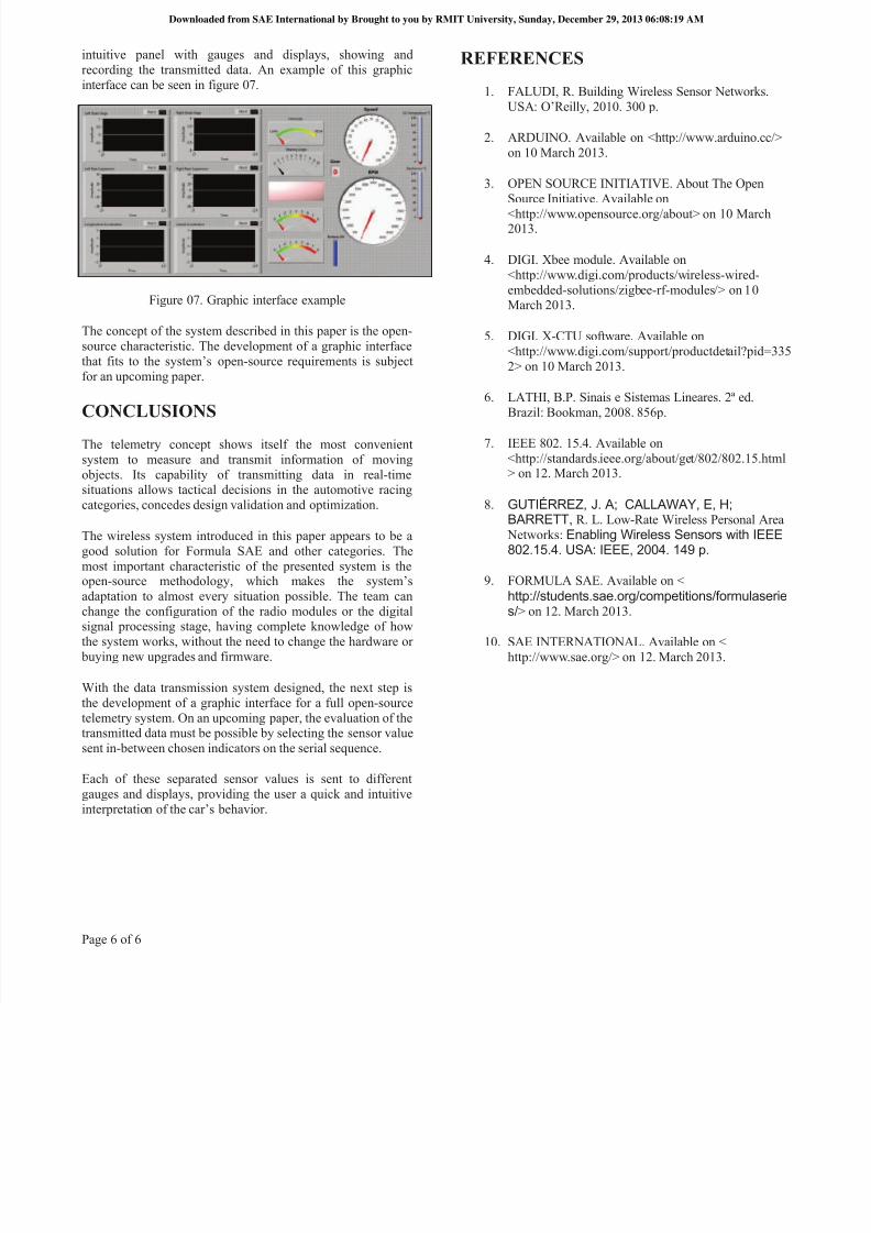
intuitive panel with gauges and displays, showing andrecording the transmitted data. An example of this graphicinterface can be seen in figure 07.
Figure 07. Graphic interface example
The concept of the system described in this paper is the open-source characteristic. The development of a graphic interfacethat fits to the system’s open-source requirements is subjectfor an upcoming paper.
CONCLUSIONS
The telemetry concept shows itself the most convenientsystem to measure and transmit information of movingobjects. Its capability of transmitting data in real-timesituations allows tactical decisions in the automotive racingcategories, concedes design validation and optimization.
The wireless system introduced in this paper appears to be agood solution for Formula SAE and other categories. Themost important characteristic of the presented system is theopen-source methodology, which m akes the system’s
adaptation to almost every situation possible. The team canchange the configuration of the radio modules or the digitalsignal processing stage, having complete knowledge of howthe system works, without the need to change the hardware or
buying new upgrades and firmware.
With the data transmission system designed, the next step isthe development of a graphic interface for a full open-sourcetelemetry system. On an upcoming paper, the evaluation of thetransmitted data must be possible by selecting the sensor valuesent in-between chosen indicators on the serial sequence.
Each of these separated sensor values is sent to differentgauges and displays, providing the user a quick and intuitiveinterpretation of the car’s behavi or.
REFERENCES
1. FALUDI, R. Building Wireless Sensor Networks.USA : O’Reilly, 2010. 300 p.
2. ARDUINO. Available on <http://www.arduino.cc/>on 10 March 2013.
3. OPEN SOURCE INITIATIVE. About The Open
Source Initiative. Available on<http://www.opensource.org/about> on 10 March2013.
4. DIGI. Xbee module. Available on<http://www.digi.com/products/wireless-wired-embedded-solutions/zigbee-rf-modules/> on 10March 2013.
5. DIGI. X-CTU software. Available on<http://www.digi.com/support/productdetail?pid=3352> on 10 March 2013.
6. LATHI, B.P. Sinais e Sistemas Lineares. 2ª ed.Brazil: Bookman, 2008. 856p.
7. IEEE 802. 15.4. Available on<http://standards.ieee.org/about/get/802/802.15.html> on 12. March 2013.
8. GUTIÉRREZ, J. A; CALLAWAY, E, H;BARRETT, R. L. Low-Rate Wireless Personal Area
Networks: Enabling Wireless Sensors with IEEE802.15.4. USA: IEEE, 2004. 149 p.
9. FORMULA SAE. Available on <
http://students.sae.org/competitions/formulaseries/> on 12. March 2013.
10. SAE INTERNATIONAL. Available on <http://www.sae.org/> on 12. March 2013.
Downloaded from SAE International by Brought to you by RMIT University, Sunday, December 29, 2013 06:08:19 AM