Embed Size (px)
Citation preview
Wireless Data Acquisition and Control
How Antennas Work
Copyright © 2008 Wilkerson Instrument Co., Inc All rights reserved
3 Element Yagi
Yagi Horizontal Beam Pattern
Omni-Directional

ANTENNA GAIN
Copyright © 2008 Wilkerson Instrument Co., Inc All rights reserved2
ABOUT ANTENNAS
The antennas in a wireless system are extremely important to the reliable performance of the system. The transmitter antenna radiates a magnetic field that must couple to the receiver antenna with sufficient strength to create a power level above the minimum threshold of the receiver. The gain of the antennas, thepolarization of the elements, the height above ground or other objects, and the lack of obstructions between the two antennas play an important role in achieving satisfactoryperformance.
REFERENCE ANTENNASGAIN
RECIPROCITY
Copyright © 2008 Wilkerson Instrument Co., Inc All rights reserved3
Antennas have a gain that is usually referenced to an isotropic source or a dipole*. The gain is the ratio of the power level out of the antenna of interest to the power level out an isotropic source or a dipole.
Gain referenced to an isotropic source is expressed in dBi while gainreferenced to a dipole is commonly expressed in dB or dBd. All antennas in this document have their gain expressed in dBi.
Antennas have perfect reciprocity. The have the same characteristicswhether used as a transmitting or receiving antenna. The gain isidentical for both applications.
*A dipole is 2 elements end to end with the RF signal fed to the ends
of the elements at the center of the 2 elements.

4
Gain is expressed as the ratio of the antenna power out (transmitting)
or in (receiving) to the reference antenna power out or in. Assume a
reference antenna is used to receive a signal from a transmitter. Then
the antenna of interest is used. The gain of the antenna of interest is:
Gain = 10Log(P2/P1) dBi
P2 = Power level of signal out of antenna of interest
P1 = Power level of signal out of reference antennaExamples:
A power ratio of 2 yields Gain = 10Log(2) Log 2 = 0.30 Gain = 3dBi
A power ratio of 10 yields Gain = 10Log(10) Log 10 = 1 Gain = 10dBi
GAIN
Copyright © 2008 Wilkerson Instrument Co., Inc All rights reserved

HOW ANTENNAS GET THEIR GAIN
(Reference Isotropic Source)
An isotropic source antenna radiates a
signal in a perfect sphere from a point
source. At a given distance from the
antenna, the signal level is the same at any
point on the sphere. There is no isotropic
antenna. It is a mathematical model only.
Gain in an antenna is achieved by shaping
the magnetic field to reduce the field in
some directions by forcing an increase
in other directions.
Copyright © 2008 Wilkerson Instrument Co., Inc All rights reserved5
Isotropic SourcePerfect Solid Sphere
Radiation Pattern
6
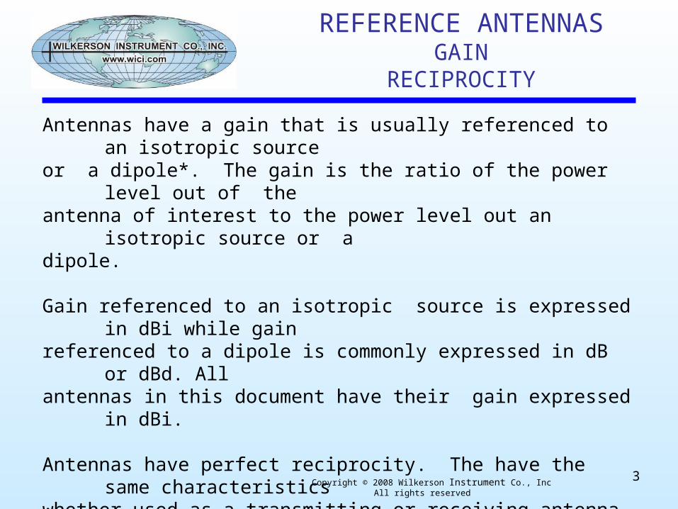
VERTICAL ANTENNAS
This image is the vertical beam pattern of a 2.1dBi gain vertical antenna. The radiation angle has been changed by the design so it radiates more in a horizontal direction with a reduction of radiation vertically. It has a doughnut shaped pattern horizontally which gives it the name "omni-directional antenna". *Wavelength is the distance between 2 zeropoints on the RF signal (sine wave).Wavelength = Velocity of wave / Frequency¼ wave at 900MHz = 3.1 inchesAll antenna design is frequency dependent.
Copyright © 2008 Wilkerson Instrument Co., Inc All rights reserved
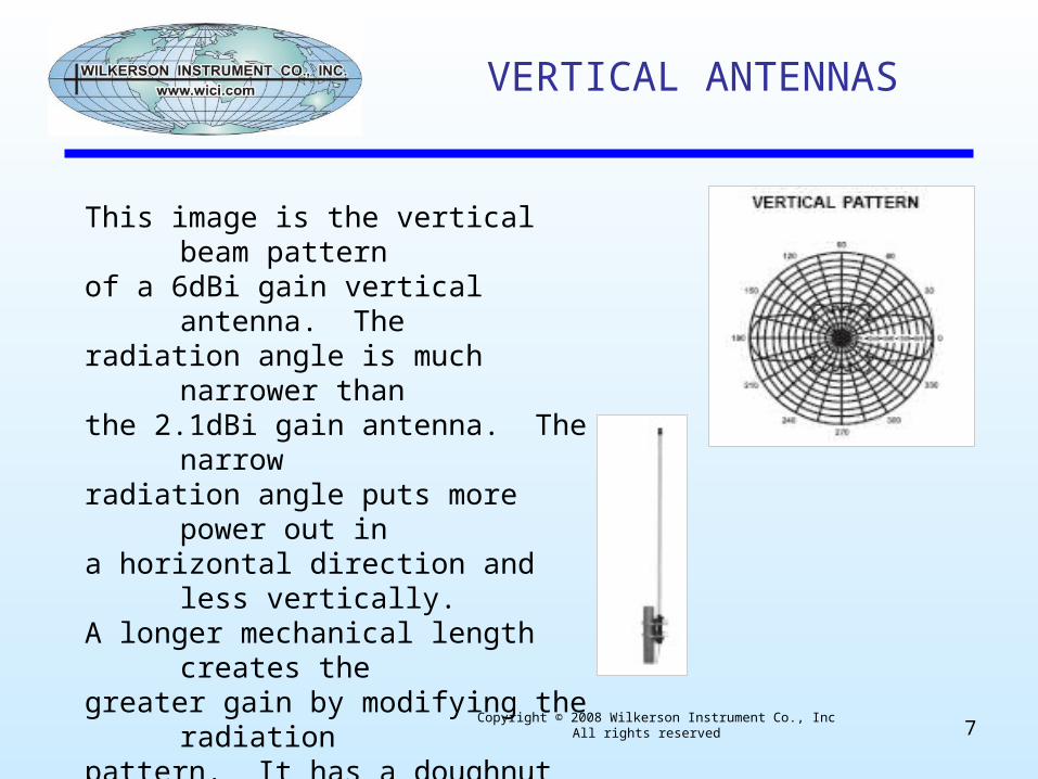
The simplest antenna is a vertical wire 1/4 wavelength* long with a
metallic plane under the bottom. It has a gain of 2.1dBi.
7
VERTICAL ANTENNAS
This image is the vertical beam patternof a 6dBi gain vertical antenna. Theradiation angle is much narrower thanthe 2.1dBi gain antenna. The narrowradiation angle puts more power out ina horizontal direction and less vertically. A longer mechanical length creates thegreater gain by modifying the radiationpattern. It has a doughnut shaped pattern horizontally.
Copyright © 2008 Wilkerson Instrument Co., Inc All rights reserved
YAGI ANTENNAS
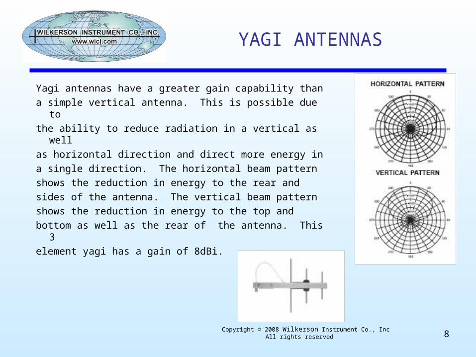
Yagi antennas have a greater gain capability than
a simple vertical antenna. This is possible due to
the ability to reduce radiation in a vertical as well
as horizontal direction and direct more energy in
a single direction. The horizontal beam pattern
shows the reduction in energy to the rear and
sides of the antenna. The vertical beam pattern
shows the reduction in energy to the top and
bottom as well as the rear of the antenna. This 3
element yagi has a gain of 8dBi.
Copyright © 2008 Wilkerson Instrument Co., Inc All rights reserved8

YAGI ANTENNAS
This 10 element yagi has a gain of 14dBi. Note the
narrower beam width in the horizontal and vertical
planes. The higher gain is achieved by narrowing
the energy into this narrower beam in the horizontal
and vertical planes.
The insensitivity of the yagi to signals from the rear
makes it a good choice for reducing interference
from the back direction.
Copyright © 2008 Wilkerson Instrument Co., Inc All rights reserved9
The difference in gain for the 2 directions is labeled the front to back ratio. This antenna has a front to back ratio of 20dB to 30dB, depending on the polarization used.

POLARIZATION
A vertical omni-directional antenna has vertical polarization. Any
antenna sending or receiving signals to/from it must have the same
polarization.
For the magnetic field around an antenna to be received by another
antenna, the magnetic field must be at a right angle to the
receiving antenna. Since the magnetic field is at a right angle to the
transmitting antenna, the 2 antennas must be parallel to each other.
A yagi must have its elements parallel to another yagi or an
omni-directional antenna. When antenna elements are cross
polarized, the signal at the receiving antenna can approach zero.Copyright © 2008 Wilkerson Instrument Co., Inc All rights reserved
10
POLARIZATION
Yagi antennas must be aligned pointing at each other and with the
same polarization. Yagi antennas must be aligned pointing at
omni-directional antennas and must have the same polarization.
Omni-directional antennas at different heights must be tilted to make
the elements parallel and the elements should be in the same plane.
Treat them as a single element yagi and point them at each other.
Antennas can provide a wide choice of gain to insure reliable operation.
The cables that connect the antennas to the receiver and transmitter
have a loss in RF energy. The resultant system gain is the antenna
gain minus the coaxial cable loss.
Copyright © 2008 Wilkerson Instrument Co., Inc All rights reserved11

SHORT RANGE ANTENNAS
Small vertical antennas are used for short range communications
7” vertical dipole antenna for indoor mounting. Mounts by screwing on RPSMA bulkhead connector. Articulated 90 degree joint allows horizontal or vertical connector to be used. Line of sight range about 1500 to 2000 feet. 2.1dBi gain
2 3/4” vertical antenna for outdoor mounting. Mounts on a special bulkhead connector . A bracket is available for mounting on a flat vertical surface or a mast. This type antenna must mount on a “ground plane” such as a metal enclosure or a metal disk. Line of sight range about 1500 to 2000 feet. 2.1 dBi gain
Vertical omni-directional antenna for outdoor mounting. Type N female connector to accept coaxial cable. Has bracket for mounting on 1 ½” mast. Line of sight range several miles.
6dBi and 8.5dBi gain models. 27” and 60” lengths.
Copyright © 2008 Wilkerson Instrument Co., Inc All rights reserved12

915MHz Band Antennas
LONG RANGE ANTENNAS
Yagi antennas with high gain are used for long range communications.
8 dBi gain 18” length
11 dBi gain 21” length
12 dBi gain 26” length
14 dBi gain 48” length
2 Stacked Yagi 17 dBi gain 48” lengthCopyright © 2008 Wilkerson Instrument Co., Inc All rights reserved 13
MAST

RECEIVER SENSITIVITY
Receiver sensitivity is usually expressed as the threshhold power level at
which the receiver detects a useable signal level. The level is expressed in
dBm (decibels referenced to 1 milliwatt across 50 ohms). Antennas and
receiver input impedance is standardized at 50 ohms.
An outstanding receiver may have a sensitivity of -110dBm, while many will
have a sensitivity of -90dBm. The 20 dB difference is a factor of 100
difference in power sensitivity. A wireless system should be designed for a
20dBm signal safety margin.
1 milliwatt across 50 ohms = 0.223V.
-90dBm = 22.3µV. A 20 dBm Safety margin = -70dBm = 223µV
-110dBm = 2.23µV. A 20 dBm Safety margin = -90dBm = 22.3µV
Copyright © 2008 Wilkerson Instrument Co., Inc All rights reserved 14

TRANSMITTER POWER
The FCC regulations for the 900MHz ISM band limits radiated power to 4 watts. If a
100mW transmitter is used, the antenna gain minus cable losses cannot exceed 16dB.
In a one way point to point system, receiver antenna gain can be anything possible. If a
transmitter is involved, the 16dB rule applies.
Transmitters radiate a sine wave AC signal. The sine wave is not perfect, therefore
harmonics of the fundamental frequency are radiated. The FCC requires the antenna to
appear to be, within limits, a 50 ohm resistor to the transmitter to keep down excessive
radiation of harmonics. To prevent improper antennas from being easily connected to ISM
transmitters, they are fitted with reverse polarity coax connectors. The reverse polarity
connectors are not easily found. A common connector is the SMA series. On a transmitter,
one will find an RPSMA connector.
Copyright © 2008 Wilkerson Instrument Co., Inc All rights reserved 15

MORE INFORMATION
Wilkerson Instrument Company is creating a group of Power Point presentations for wireless
applications, and other instrumentation problem solving applications.
We are also creating application notes in a pdf format for the same subjects.
The slide presentations and application notes can be viewed on our web site www.wici.com.
These aids can be downloaded.
The slide presentations and application notes will also be on our CD Wireless Data
Acquisition Products and Instrumentation Products catalogs. These catalog CD’s can be downloaded
or they can be requested from [email protected]. Tel .800 234 1343.
The application notes will be added to our email broadcast list. If you would like to be
added to our list, please send a note to [email protected].
Richard Huffman
President
Wilkerson Instrument Company, Inc
Copyright © 2008 Wilkerson Instrument Co., Inc All rights reserved 16

Need More Information!
Wilkerson Instrument Co., Inc. 2915 Parkway Street Lakeland, FL 33811
Toll Free: 800-234-1343 Phone: 863-647-2000 Fax: 863-644-5318 Email: [email protected]
Complete documentation is available for all Wilkerson Instrument Co. products at www.wici.com.
Copyright © 2008 Wilkerson Instrument Co., Inc All rights reserved17


![dRTI: Directional Radio Tomographic Imagingwenh/bo_ipsn15_drti.pdf · 2015. 3. 8. · less networks previously [3, 12]. However, traditional di-rectional antennas such as Yagi antennas](https://img.pdfslide.us/doc/110x75/600991415280c625cd7a5a88/drti-directional-radio-tomographic-wenhboipsn15drtipdf-2015-3-8-less.jpg)