Embed Size (px)
Citation preview
WIRELESS CONTROLLED
ROBOTIC AUTOMATION SYSTEM
A thesis submitted in partial fulfilment of the requirement for the degree of
M.Tech Dual Degree
In
Electronics and Instrumentation Engineering
Specialization: VLSI & Embedded Systems
By
Sanjeet Kumar Behera
Roll No: 710EC2042
Department of Electronics and Communication Engineering,
National Institute of Technology Rourkela,
Rourkela, Odisha, 769008, India,
June 2015.
WIRELESS CONTROLLED
ROBOTIC AUTOMATION SYSTEM
A thesis submitted in partial fulfilment of the requirement for the degree of
M.Tech Dual Degree
In
Electronics and Instrumentation Engineering
Specialization: VLSI & Embedded Systems
By
Sanjeet Kumar Behera
Roll No: 710EC2042
Under the Guidance of
Prof. D.P.Acharya
Department of Electronics and Communication Engineering,
National Institute of Technology Rourkela,
Rourkela, Odisha, 769008, India,
June 2015.
i | P a g e
DEPARTMENT OF ELECRTONICS AND COMMUNICATION ENGINEERING,
NATIONAL INSTITUTE OF TECHNOLOGY,
ROURKELA, ODISHA -769008.
CERTIFICATE
This is to certify that the work done in the thesis entitled Wireless Controlled
Robotic Automation System by Sanjeet Kumar Behera is a record of an original
research work carried out by her in National Institute of Technology, Rourkela
under my supervision and guidance during 2014-2015 in partial fulfilment for the
award of M.Tech Dual Degree in Electronics and Instrumentation Engineering
(VLSI & Embedded Systems), National Institute of Technology, Rourkela.
Place: NIT Rourkela Dr. D.P.Acharya
Date:. Associate Professor
ii | P a g e
DEPARTMENT OF ELECRTONICS AND COMMUNICATION
ENGINEERING, NATIONAL INSTITUTE OF TECHNOLOGY,
ROURKELA, ODISHA -769008.
DECLARATION
I certify that,
a. The work presented in this thesis is an original content of the
research done by myself under the general supervision of my
supervisor.
b. The project work or any part of it has not been submitted to any
other institute for any degree or diploma.
c. I have followed the guidelines prescribed by the Institute in
writing my thesis.
d. I have given due credit to the materials (data, theoretical analysis
and text) used by me from other sources by citing them wherever
I used them and given their details in the references.
e. I have given due credit to the sources (written material) used by
quoting them where I used them and have cited those sources.
Also their details are mentioned in the references.
Sanjeet Kumar Behera

iii | P a g e
ACKNOWLEDGEMENT
This research work is partly made possible because of the continuous motivation by
so many people from every part of my life. I convey my deepest regards and sincere thanks to
my supervisor Dr. D.P.Acharya for his esteemed direction and support throughout the period
of this research work.
I would also like to thank all the faculty members of the Department of Electronics
and Communication Engineering, NIT Rourkela for their valuable help in the completion of
my thesis work.
I extend my gratitude and sincere thanks to the fellow students and research scholars
at Reconfigurable IC Lab, Department of ECE for their constant motivation and cooperation
throughout the tenure of this work.
Finally, I would like to express my sincere thanks to my family and friends for their
unending encouragement and sharing of experiences, and without whose support this work
could never have been completed successfully.
Sanjeet Kumar Behera
iv | P a g e
ABSTRACT
The project is to develope a controller and to control a 6 DOF robotic arm for Pick &
Place Application over wireless. The objective is to learn various types of control methods
for the pick and place robotic arm for educational purpose uses. The 6-DOF robot arm is
controlled by a serial servo controller circuit board. The controller board utilizes a
Atmega328 microcontroller ( Boot loaded with Arduino Diecimila Bootloader ) from Atmel
Corporation as the control system to control all the activities. The input sensors like
potentiometers will send a the input signals to the microcontroller, then microcontroller will
analyze the data accordingly and will send control signals to the output devices. This output
signal basically turns ON or OFF the output devices such as servo motors. The servo
controller board is connected to the serial port on a PC running the Microsoft Windows
operating system. The ATMega328 will be programmed to run robot arm sequences
independently by help of a FT232RL breakout board. Arduino integrated development
environment (IDE) is used to develop the arduino sketch.
Various types of control methods have been implemented. Manual control of the
Robotic arm by mirroring the designed prototype movements. Prototype was developed by
help of sensors like potentiometers. Also automated control of the robotic arm has been
realized. The controller is also interfaced with a XBee XBP24-AWI-001 wireless module for
remote control of the robotic arm from a PC using a graphical user interface (GUI), which
was designed using processing development environment (PDE).The EEPROM present in
Atmega328 MC unit has been utilized to make the robotic arm learnable. i.e. it can learn the
movements stored in the memory and can replay it whenever prompted remotely.
Programming is done remotely and the output data is sent over wireless to control the robotic
arm.
v | P a g e
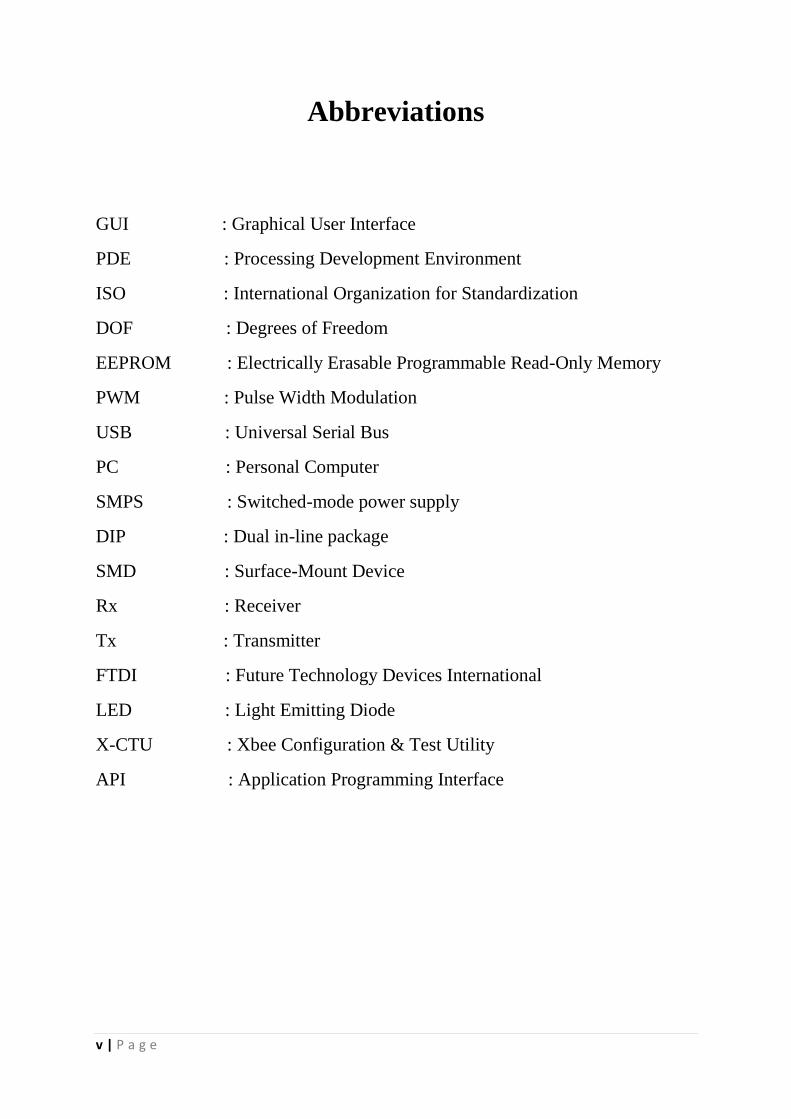
Abbreviations
GUI : Graphical User Interface
PDE : Processing Development Environment
ISO : International Organization for Standardization
DOF : Degrees of Freedom
EEPROM : Electrically Erasable Programmable Read-Only Memory
PWM : Pulse Width Modulation
USB : Universal Serial Bus
PC : Personal Computer
SMPS : Switched-mode power supply
DIP : Dual in-line package
SMD : Surface-Mount Device
Rx : Receiver
Tx : Transmitter
FTDI : Future Technology Devices International
LED : Light Emitting Diode
X-CTU : Xbee Configuration & Test Utility
API : Application Programming Interface
vi | P a g e
List of Figures
Figure N0. Title Page No.
Figure 1.1. Robotic Arm Architecture ...............................................................................3
Figure 1.2. The Block Diagram of the Robotic Arm .........................................................4
Figure 1.3. Project Overview of wireless controlled Robotic Arm ...................................5
Figure 1.4. Flowchart of the Project ..................................................................................7
Figure 2.1. 6 DOF Robotic Arm ........................................................................................9
Figure 2.2. High Torque Standard Servo……………………………………………….11
Figure 2.3. a. Atmega328 DIP………………………………………………………….11
Figure 2.3. b. Atmega328 SMD………………………………………………………...11
Figure 2.4. Atmega328 Pin Mapping…………………………………………………..12
Figure 2.5. XBee Pro 60mw Wire Antenna-Series……………………………………. 13
Figure 2.6. XBee Explorer Regulated with 3v3 to 5V Converter………………………15
Figure 2.7. XBee Explorer Dongle……………………………………………………..16
Figure 2.8. FOCA FT232 USB to Serial Adapter……………………………………...17
Figure 3.1. Arduino Development Environment……………………………………….19
Figure 3.2. Processing Development Environment…………………………………….21
Figure 3.3. GUI Builder Tool…………………………………………………………..22
Figure 3.4. X-CTU Configuration Window……………………………………………24
Figure 3.5. Fritzing Schematic Window View…………………………………………25
Figure 4.1. Power Module Circuitry……………………………………………………26
Figure 4.2. a. Breadboard View of Microcontroller Board…………………………….27
Figure 4.2. b. Schematic View of Microcontroller Board……………………………...27
Figure 4.3. Breadboard View of Manual Controller Interfaced With the Robotic Arm.28
Figure 4.4. Flowchart For Mirroring the Manual Controller Movements……………..29
Figure 4.5. Overview pf Wireless Control Using GUI………………………………...30
Figure 4.6. Receiving End Interfacing…………………………………………………30
Figure 4.7. Flowchart For Data Transmission over Xbee……………………………...31
Figure 4.8. Flowchart For Data Reception over Xbee…………………………………32
Figure 4.9. Transmitting End Schematics of Trainable Robotic Arm…………………33
Figure 4.10 Flowchart For Trainable Robotic Arm……………………………………34
Figure 5.1. Manual Controller Prototype………………………………………………35
Figure 5.2. Developed Microcontroller Boards………………………………………..36
Figure 5.3. Developed Power Module…..……………………………………………..37
Figure 5.4. Actual Robotic Arm Structure……………………………………………..37
vii | P a g e
INDEX Certificate ..................................................................................................................................i Declaration............................................................................................................................... ii Abstrac3 ...................................................................................................................................iv List of figures ...........................................................................................................................v Chapter 1 ..................................................................................................................................1 Introduction ..............................................................................................................................1
1.1. Introduction .....................................................................................................................1
1.2. Project Background .........................................................................................................1
1.3. Literature Review ............................................................................................................2
1.3.1. Existing Projects ....................................................................................................2
1.3.2. Pick and Place Robotic Arm Controlled By Computer ..........................................3
1.3.3. Design and Operation of Synchronized Robotic Arm ............................................4
1.3.4. Pick and Place Robot (Robotic Arm) .....................................................................4
1.3.5. Wireless Mobile Robotic Arm ................................................................................5
1.4. Objectives ........................................................................................................................5
1.4.1. Design and Fabrication of Power Module Circuitry ............................................5
1.4.2. Design and Fabrication of Serial Servo Controller ..............................................6
1.4.3. Development of Robot Software ............................................................................6
1.4.4. Interfacing with the Robot Arm .............................................................................6
1.5. Methodology ...................................................................................................................6
1.6. Thesis Organization.........................................................................................................8
Chapter 2 ..................................................................................................................................9 Hardware Overview.................................................................................................................9
2.1. 6 DOF Robotic Arm ........................................................................................................9
2.1.1 Robotic Arm Features ........................................................................................10
2.2. High Torque Standard Servos .......................................................................................10
2.2.1 Servo Specifications ...........................................................................................10
2.2.1 Servo Specifications ...........................................................................................10
2.3. Atmega328 Microcontroller..........................................................................................11
2.3.1 Atmega328 Microcontroller Pin Mapping .........................................................12
2.3.2 Atmega328 Microcontroller Specifications .......................................................12
viii | P a g e
2.4. XBee Pro 60mw Wire Antenna-Series 1 ......................................................................13
2.4.1 XBee Pro Features .............................................................................................13
2.5. XBee Explorer Regulated with 3v3 to 5V Converter ...................................................14
2.5.1 XBee Explorer Regulated Features ....................................................................14
2.6. XBee Explorer Dongle ..................................................................................................15
2.6.1 XBee Explorer Dongle Features ........................................................................15
2.7. FOCA FT232 USB to Serial Adapter ...........................................................................16
2.7.1 FOCA FT232 Features.......................................................................................16
2.7.2 FOCA FT232 Specifications ..............................................................................17
Chapter 3 ................................................................................................................................18 Software Overview .................................................................................................................18
3.1 Arduino Development Environment ..............................................................................18
3.1.1 Writing Codes ..........................................................................................................18
3.1.2 Sketchbook ...............................................................................................................18
3.1.3 Libraries ..................................................................................................................18
3.1.4 Serial Monitor..........................................................................................................19
3.2 Processing.......................................................................................................................20
3.2.1 Processing Development Environment ....................................................................20
3.2.2 G4P GUI Library.....................................................................................................22
3.2.3 G4P GUI Builder Tool ............................................................................................22
3.3 X-CTU ( Xbee Configuration & Test Utility ) ...............................................................23
3.4 Fritzing ...........................................................................................................................25
Chapter 4 ................................................................................................................................26 Hardware Implementation & Programming ......................................................................26
4.1 Design and Fabrication of Power Module Circuitry ......................................................26
4.2 Design and Fabrication of Microcontroller Board .........................................................26
4.2.1 Basic Parts Needed ..................................................................................................26
4.2.2 Circuitry of the Developed Board ...........................................................................27
4.3 Development of small prototype Manual Controller .....................................................28
4.3.1 Controlling of the Robotic Arm By Mirroring the Movements of the Manual
Controller Prototype.........................................................................................................29
ix | P a g e
4.4 Wireless Control of The Robotic Arm Using A GUI.....................................................30
4.5 Wireless Control of a Trainable Robotic Arm .............................................................33
Chapter 5 ................................................................................................................................35 Results and Discussions .........................................................................................................35
5.1 Developed Manual Controller Prototype .......................................................................35
5.2 Developed Circuitry .......................................................................................................36
5.3 Actual Robotic Arm Structure .......................................................................................37
5.2 Complete Programming Source Code ............................................................................37
Chapter 6 ................................................................................................................................38 Conclusions .............................................................................................................................38
6.1 Conclusion ......................................................................................................................38
References ...............................................................................................................................39
1 | P a g e
CHAPTER 1
Introduction
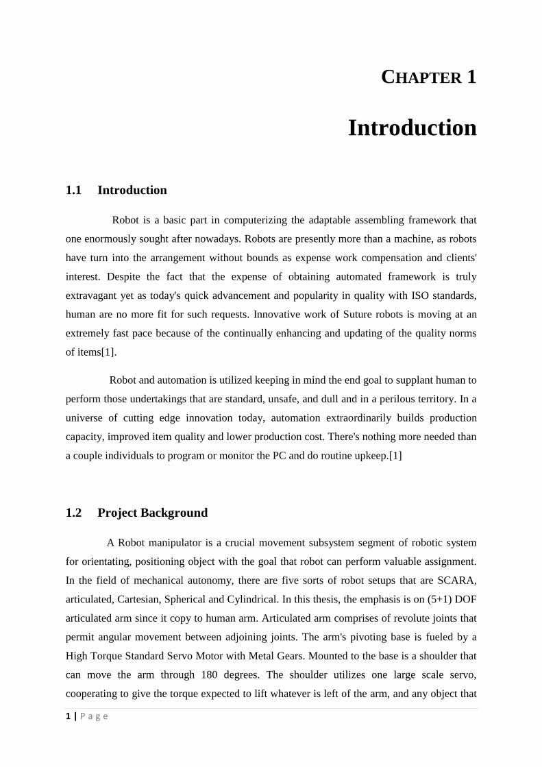
1.1 Introduction
Robot is a basic part in computerizing the adaptable assembling framework that
one enormously sought after nowadays. Robots are presently more than a machine, as robots
have turn into the arrangement without bounds as expense work compensation and clients'
interest. Despite the fact that the expense of obtaining automated framework is truly
extravagant yet as today's quick advancement and popularity in quality with ISO standards,
human are no more fit for such requests. Innovative work of Suture robots is moving at an
extremely fast pace because of the continually enhancing and updating of the quality norms
of items[1].
Robot and automation is utilized keeping in mind the end goal to supplant human to
perform those undertakings that are standard, unsafe, and dull and in a perilous territory. In a
universe of cutting edge innovation today, automation extraordinarily builds production
capacity, improved item quality and lower production cost. There's nothing more needed than
a couple individuals to program or monitor the PC and do routine upkeep.[1]
1.2 Project Background
A Robot manipulator is a crucial movement subsystem segment of robotic system
for orientating, positioning object with the goal that robot can perform valuable assignment.
In the field of mechanical autonomy, there are five sorts of robot setups that are SCARA,
articulated, Cartesian, Spherical and Cylindrical. In this thesis, the emphasis is on (5+1) DOF
articulated arm since it copy to human arm. Articulated arm comprises of revolute joints that
permit angular movement between adjoining joints. The arm's pivoting base is fueled by a
High Torque Standard Servo Motor with Metal Gears. Mounted to the base is a shoulder that
can move the arm through 180 degrees. The shoulder utilizes one large scale servo,
cooperating to give the torque expected to lift whatever is left of the arm, and any object that
2 | P a g e
it might be picking up. Appended to the shoulder piece is an elbow that can travel through
180 degrees. The wrist is comprised of one standard servo and can travel through 180 degrees
and additionally turning the gripper clockwise and counter clockwise. Appended to the wrist
is a two fingered gripper that uses a unique arrangement constructed around a standard
servo.[1]
The robot arm is controlled by a serial servo controller circuit board. The controller
circuit board is in view of Atmega328 microcontroller with Arduino Diecimila Bootloader.
The serial servo controller board will be associated with the serial port on a PC running the
Microsoft Windows working framework. The ATMega328 MC board will be programmed by
help of a FT232RL breakout board to run robot arm. Manual control of the Robotic arm by
mirroring the designed prototype movement. Prototype will be developed by help of sensors
like potentiometers. Also automated control of the robotic arm will be realized. The
controller will also be interfaced with a XBee XBP24-AWI-001 wireless module for remote
control of the robotic arm from a PC using a graphical user interface (GUI), which will be
designed using processing development environment (PDE).The EEPROM present in
Atmega328 MC unit will be utilized to make the robotic arm learnable. i.e. it can learn the
movements stored in the memory and can replay it whenever prompted remotely.
Programming will be done remotely and the output data will be sent over wireless to control
the robotic arm.
1.3 Literature Review
The fundamental thought of writing Literature review is to get enough important
data and learning on comparative undertakings done by others. A couple projects and
researches done already by researchers or scholars will be discussed here.
1.3.1 Existing Projects
For as far back as years, numerous have endeavored to design, make and build
robotic arms utilizing diverse methodologies. The following are a portion of the activities
which are firmly identified with the idea of a pick and place robotic arm.
3 | P a g e
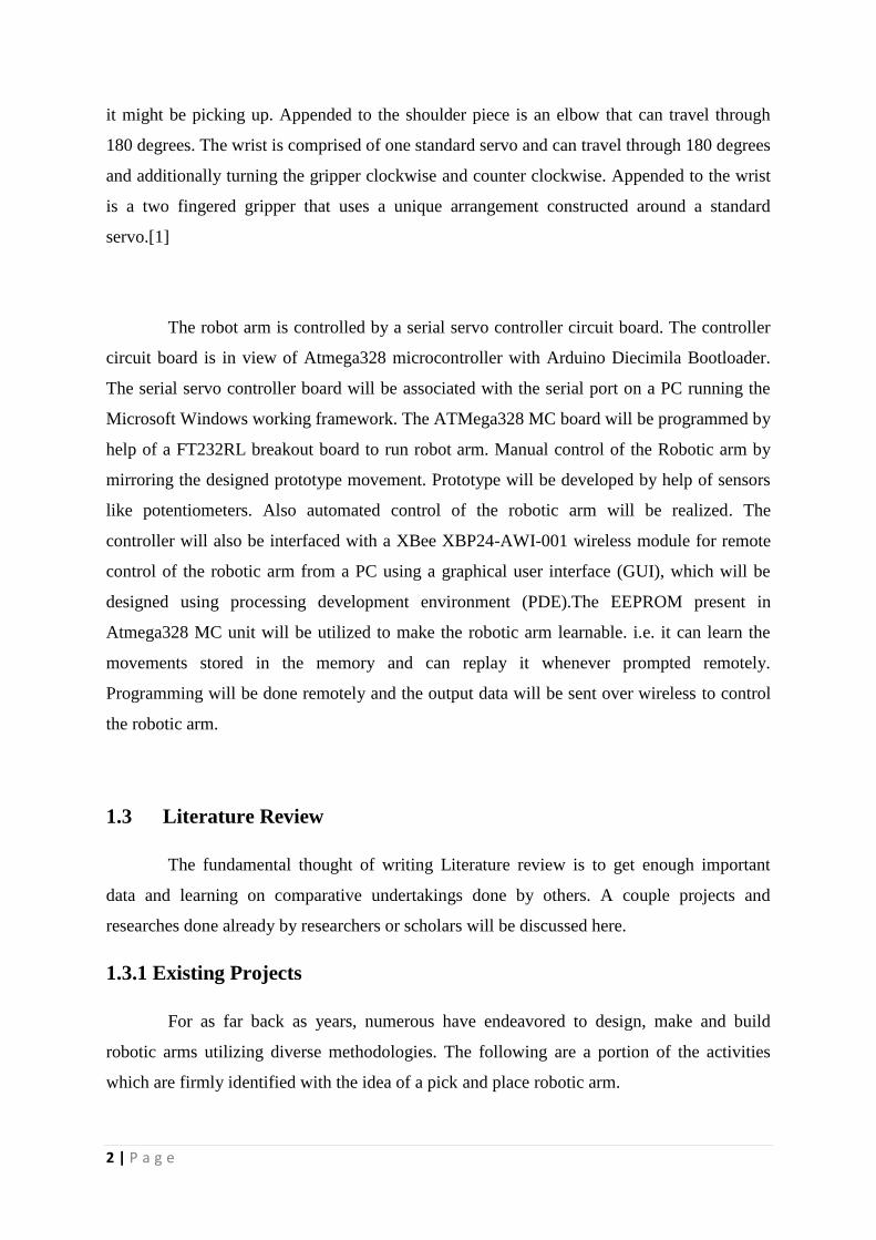
1.3.2 Pick and Place Robotic Arm Controlled By Computer
In this proposition the robot arm is controlled by a serial servo controller circuit
board. The controller circuit board is controlled or operated by Microchip’s PIC16F84A
(flash programmable) microcontroller. The serial servo controller board will be connected to
the serial port of a PC operated with windows OS. Visual Basic 6 was used to develop the
program for controlling the robot arm from PC. The PIC 16F84A has the functionality to run
independent robot arm sequences. a voice recognition circuit integration was also done [1].
Figure 1.1: Robotic Arm Architecture [1].
4 | P a g e
1.3.3 Design and Operation of Synchronized Robotic Arm
The paper deals with the arranging and utilization of Synchronized Robotic Arm,
which is used to perform all the fundamental activities like picking materials and putting
them. In this paper, a robotic arm is made, synchronized with a working arm, and would
perform the undertaking as the working arm does. The programming of ATMEGA-8
Microcontroller is finished by using Arduino IDE. The potentiometers are in like manner
used to recognize the angle of rotation and the signals are then fed to the microcontroller.
Other than Robotics and Automation, these sorts of arms have applications in distinctive
fields [2].
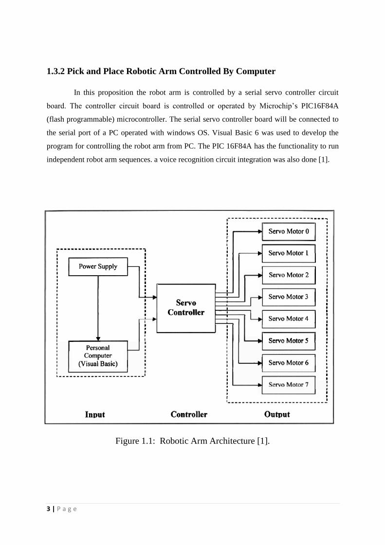
1.3.4 Pick and Place Robot (Robotic Arm)
This project is about the construction and design of a pick and place robotic arm
using a PIC microcontroller. Main objective is to build a more compact and cheaper robotic
arm intended for educational means. Here IR sensors act as input devices and the sensors will
send the signal which will be analyzed by the PIC microcontroller and will response
correspondingly [3].
Figure 1.2: The Block Diagram of the Robotic Arm [3].

5 | P a g e
1.3.5 Wireless Mobile Robotic Arm
Advancement of a wireless robot is exhibited in this paper. A portable pick and
place robot controlled by utilizing remote PS2 controller. The robot controller is in view of
Arduino Mega microcontroller that is interfaced with the remote controller and afterwards to
the portable mechanical arm [4]. Different analyses, for example, distance, speed & load that
can be picked of the robot has been done so as to know its execution [4].
Figure 1.3: Project Overview of wireless controlled Robotic Arm [4].
1.4 Objectives
The fundamental objective in finishing the project will be to accomplish the
norms that have been set. The destinations are as per the following:
1.4.1 Fabrication & design of Power Module Circuitry
Essentially it’s a rectifier circuit that changes over AC, which periodically changes
to DC, which is unidirectional. The process is called rectification.. The objective is to
calculate the capacitance of the input filter capacitor and to design the rectifier circuit to
convert the 220v input AC to required output of 5v and 12v DC.
6 | P a g e
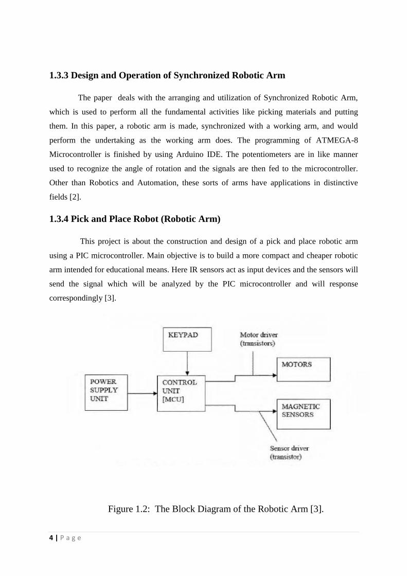
1.4.2 Fabrication Design and of Servo Controller
The principle goal is to design and manufacture the servo controller circuit board
that will be utilized to control the robot arm servo wirelessly with the controller board. The
most essential part that is utilized as a part of the controller is the Atmega328
microcontroller.
1.4.3 Development of Robot Software
The following fundamental goal is to develop a code utilizing Arduino IDE
programming to control the servo controller circuit board. The program will operate the
Atmega328 on the controller circuit. ATMega328 will generate the PWM signals with proper
delays to position the robotic arm.
1.4.4 Microcontroller and the Robot Arm interfacing
Here the objective is to make both wired & wireless interfacing of the robotic arm to
the controller board. For wireless communication XBee XBP24-AWI-001 wireless modules
are used.
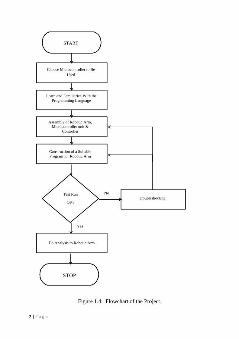
1.5 Methodology
The whole project can be separated into two main parts. At first design and
implementation of the hardware and circuitries and the second will be development of the
Arduino code for the pick & place operation.
The flowchart of the project is shown in Figure 1.4.
7 | P a g e
START
Choose Microcontroller to Be
Used
Learn and Familiarize With the
Programming Language
Assembly of Robotic Arm,
Microcontroller unit &
Controller
Construction of a Suitable
Program for Robotic Arm
Test Run
OK?
Yes
No
Do Analysis to Robotic Arm
Troubleshooting
STOP
Figure 1.4: Flowchart of the Project.
8 | P a g e
1.6 Thesis Organization
Chapter-1: The ongoing chapter gives a brief introduction to the project. The project
background is followed by some literature reviews. The objectives of this project and the
methodologies carried out to implement it have been discussed in this chapter.
Chapter-2: In this chapter the hardware overview has been discussed. The 6 DOF Robotic
arm and high torque standard servos have been studied in details. The detailed theory of
Atmega328 microcontroller and XBee have been given in this chapter.
Chapter-3: Softeware overview has been cited in this chapter. The details of the two
softwares Arduino Development Environment and Processing has been given followed by the
detailed study of X-CTU and Fritzing.
Chapter-4: The hardware implementation and programming have been discussed in this
chapter. Design and fabrication of Power Module Circuitry and Microcontroller Board haven
carried out. This chapter also cites the development of small prototype manual controller
followed by the depiction of wireless control of the robotic arm using GUI and a trainable
robotic arm.
Chapter-5: This chapter gives the complete results of the programmes carried out throughout
the project followed by some discussions.
Chapter-6: The conclusion of the thesis is shown in this chapter.
9 | P a g e
CHAPTER 2
Hardware Overview
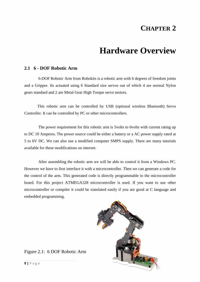
2.1 6 - DOF Robotic Arm
6-DOF Robotic Arm from Robokits is a robotic arm with 6 degrees of freedom joints
and a Gripper. Its actuated using 6 Standard size servos out of which 4 are normal Nylon
gears standard and 2 are Metal Gear High Torque servo motors.
This robotic arm can be controlled by USB (optional wireless Bluetooth) Servo
Controller. It can be controlled by PC or other microcontrollers.
The power requirement for this robotic arm is 5volts to 6volts with current rating up
to DC 10 Amperes. The power source could be either a battery or a AC power supply rated at
5 to 6V DC. We can also use a modified computer SMPS supply. There are many tutorials
available for these modifications on internet.
After assembling the robotic arm we will be able to control it from a Windows PC.
However we have to first interface it with a microcontroller. Then we can generate a code for
the control of the arm. This generated code is directly programmable to the microcontroller
board. For this project ATMEGA328 microcontroller is used. If you want to use other
microcontroller or compiler it could be translated easily if you are good at C language and
embedded programming.
Figure 2.1: 6 DOF Robotic Arm
10 | P a g e
2.1.1 Robotic Arm Features
• Maximum degrees of freedom is six. ( 5+Gripper )
• It can reach maximum a distance of 350 mm from its base.
• Minimum power requirement for operation is 5 to 6 Volts DC ( 4 Amp )
• It can pick up a Maximum Payload of 270 Grams.
• It has four nylon gear and two metal gear high torque servos.
2.2 High Torque Standard Servos
The servo motors with metal gears provide different values of torque depending upon
the supply voltage. For example 11kg *cm at 4.8V, 13.5kg*cm at 6V and 16kg*cm at 7.2V.
2.2.1 Servo Specifications
1. Minimum Required Pulse: 3-5 Volt (Peak to Peak)
2. Square Wave Operating Voltage: 4.8-7.2 Volts
3. Operating Temperature Range: -10 to +60 Degree
4. Operating Speed at different operating voltages
At 4.8V speed is 0.18sec/60 degrees without load
At 6V speed is 0.16sec/60 degrees without load
At 7.2V speed is 0.14sec/60 degrees without load
5. Stall Torque at different operating voltages
At 4.8V is 11kg/cm.
At 6V is 13.5kg/cm
At 7.2V is 16kg/cm.
6. Servos can be modifiable up to 360 degrees.
7. Servos are double ball bearing type with all metal gears.
11 | P a g e
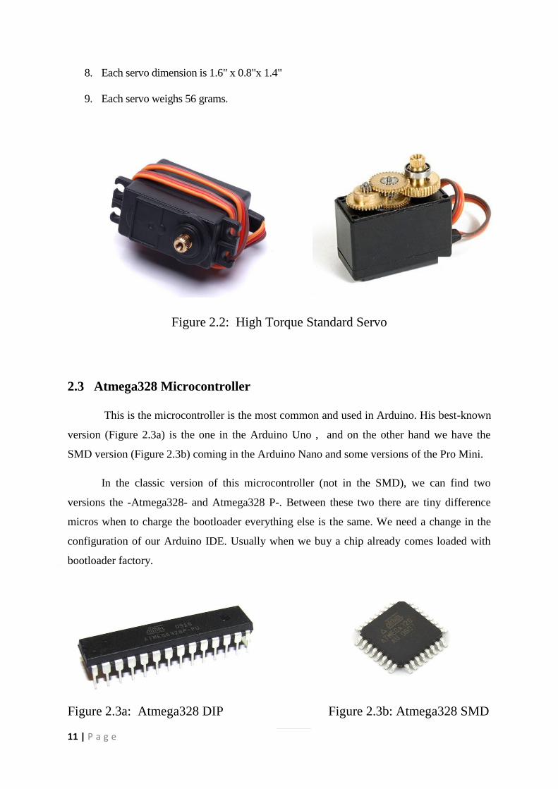
8. Each servo dimension is 1.6" x 0.8"x 1.4"
9. Each servo weighs 56 grams.
Figure 2.2: High Torque Standard Servo
2.3 Atmega328 Microcontroller
This is the microcontroller is the most common and used in Arduino. His best-known
version (Figure 2.3a) is the one in the Arduino Uno , and on the other hand we have the
SMD version (Figure 2.3b) coming in the Arduino Nano and some versions of the Pro Mini.
In the classic version of this microcontroller (not in the SMD), we can find two
versions the -Atmega328- and Atmega328 P-. Between these two there are tiny difference
micros when to charge the bootloader everything else is the same. We need a change in the
configuration of our Arduino IDE. Usually when we buy a chip already comes loaded with
bootloader factory.
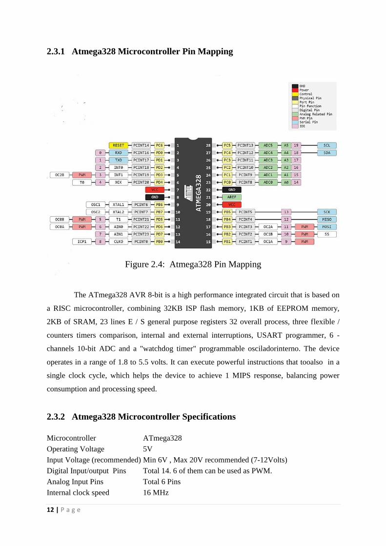
Figure 2.3a: Atmega328 DIP Figure 2.3b: Atmega328 SMD
12 | P a g e
2.3.1 Atmega328 Microcontroller Pin Mapping
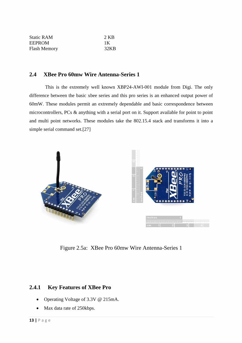
Figure 2.4: Atmega328 Pin Mapping
The ATmega328 AVR 8-bit is a high performance integrated circuit that is based on
a RISC microcontroller, combining 32KB ISP flash memory, 1KB of EEPROM memory,
2KB of SRAM, 23 lines E / S general purpose registers 32 overall process, three flexible /
counters timers comparison, internal and external interruptions, USART programmer, 6 -
channels 10-bit ADC and a "watchdog timer" programmable osciladorinterno. The device
operates in a range of 1.8 to 5.5 volts. It can execute powerful instructions that tooalso in a
single clock cycle, which helps the device to achieve 1 MIPS response, balancing power
consumption and processing speed.
2.3.2 Atmega328 Microcontroller Specifications
Microcontroller ATmega328
Operating Voltage 5V
Input Voltage (recommended) Min 6V , Max 20V recommended (7-12Volts)
Digital Input/output Pins Total 14. 6 of them can be used as PWM.
Analog Input Pins Total 6 Pins
Internal clock speed 16 MHz
13 | P a g e
Static RAM 2 KB
EEPROM 1K
Flash Memory 32KB
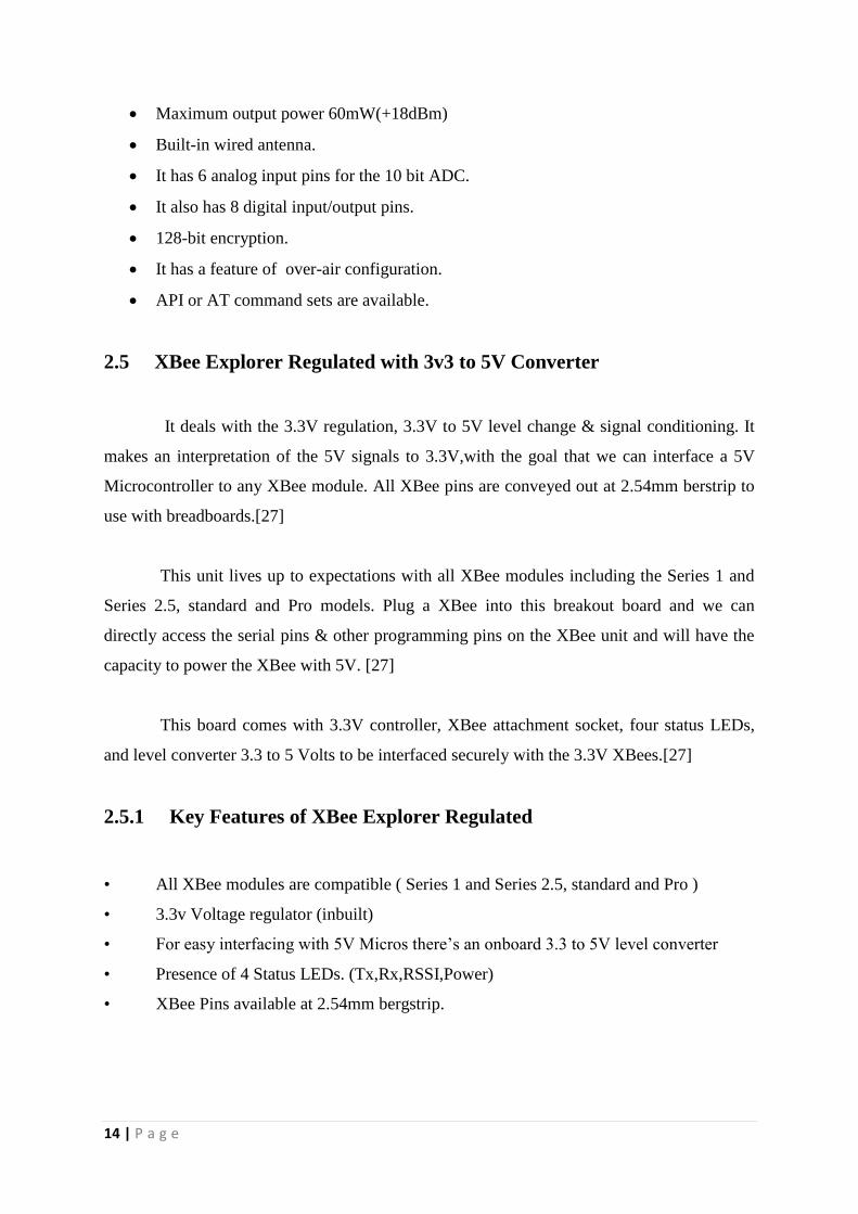
2.4 XBee Pro 60mw Wire Antenna-Series 1
This is the extremely well known XBP24-AWI-001 module from Digi. The only
difference between the basic xbee series and this pro series is an enhanced output power of
60mW. These modules permit an extremely dependable and basic correspondence between
microcontrollers, PCs & anything with a serial port on it. Support available for point to point
and multi point networks. These modules take the 802.15.4 stack and transforms it into a
simple serial command set.[27]
Figure 2.5a: XBee Pro 60mw Wire Antenna-Series 1
2.4.1 Key Features of XBee Pro
Operating Voltage of 3.3V @ 215mA.
Max data rate of 250kbps.
14 | P a g e
Maximum output power 60mW(+18dBm)
Built-in wired antenna.
It has 6 analog input pins for the 10 bit ADC.
It also has 8 digital input/output pins.
128-bit encryption.
It has a feature of over-air configuration.
API or AT command sets are available.
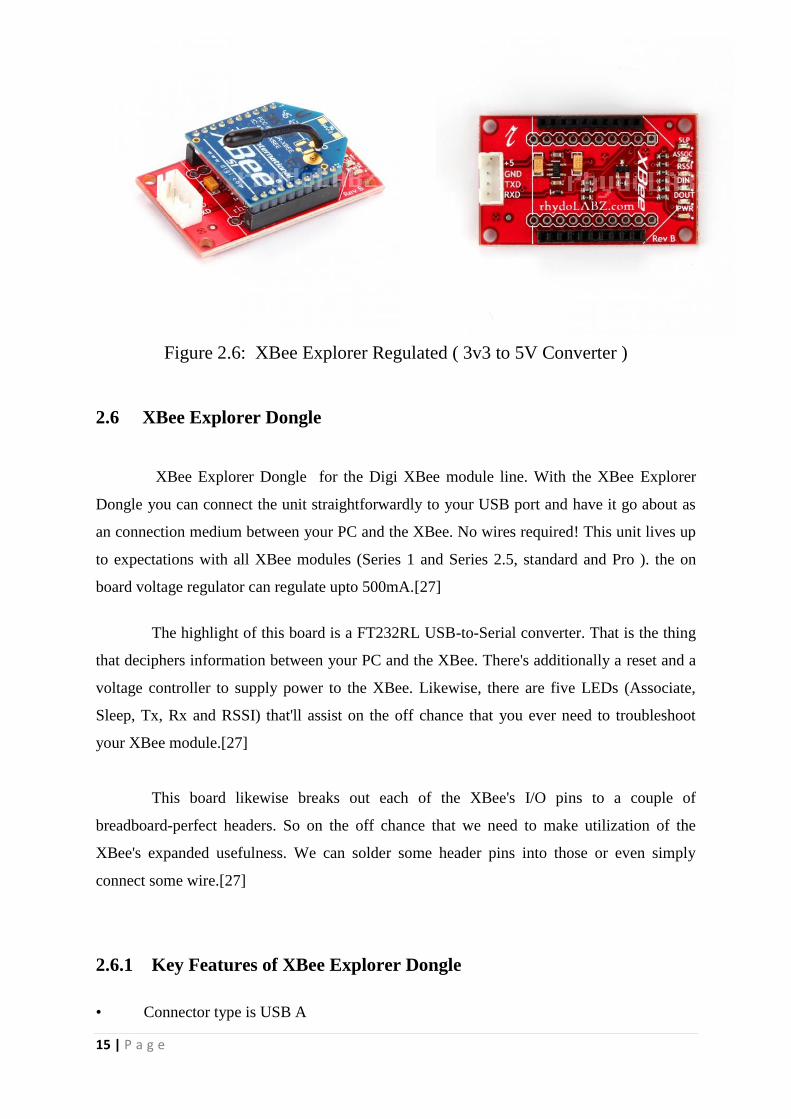
2.5 XBee Explorer Regulated with 3v3 to 5V Converter
It deals with the 3.3V regulation, 3.3V to 5V level change & signal conditioning. It
makes an interpretation of the 5V signals to 3.3V,with the goal that we can interface a 5V
Microcontroller to any XBee module. All XBee pins are conveyed out at 2.54mm berstrip to
use with breadboards.[27]
This unit lives up to expectations with all XBee modules including the Series 1 and
Series 2.5, standard and Pro models. Plug a XBee into this breakout board and we can
directly access the serial pins & other programming pins on the XBee unit and will have the
capacity to power the XBee with 5V. [27]
This board comes with 3.3V controller, XBee attachment socket, four status LEDs,
and level converter 3.3 to 5 Volts to be interfaced securely with the 3.3V XBees.[27]
2.5.1 Key Features of XBee Explorer Regulated
• All XBee modules are compatible ( Series 1 and Series 2.5, standard and Pro )
• 3.3v Voltage regulator (inbuilt)
• For easy interfacing with 5V Micros there’s an onboard 3.3 to 5V level converter
• Presence of 4 Status LEDs. (Tx,Rx,RSSI,Power)
• XBee Pins available at 2.54mm bergstrip.
15 | P a g e
Figure 2.6: XBee Explorer Regulated ( 3v3 to 5V Converter )
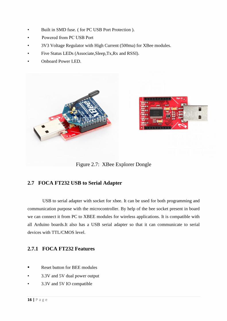
2.6 XBee Explorer Dongle
XBee Explorer Dongle for the Digi XBee module line. With the XBee Explorer
Dongle you can connect the unit straightforwardly to your USB port and have it go about as
an connection medium between your PC and the XBee. No wires required! This unit lives up
to expectations with all XBee modules (Series 1 and Series 2.5, standard and Pro ). the on
board voltage regulator can regulate upto 500mA.[27]
The highlight of this board is a FT232RL USB-to-Serial converter. That is the thing
that deciphers information between your PC and the XBee. There's additionally a reset and a
voltage controller to supply power to the XBee. Likewise, there are five LEDs (Associate,
Sleep, Tx, Rx and RSSI) that'll assist on the off chance that you ever need to troubleshoot
your XBee module.[27]
This board likewise breaks out each of the XBee's I/O pins to a couple of
breadboard-perfect headers. So on the off chance that we need to make utilization of the
XBee's expanded usefulness. We can solder some header pins into those or even simply
connect some wire.[27]
2.6.1 Key Features of XBee Explorer Dongle
• Connector type is USB A
16 | P a g e
• Built in SMD fuse. ( for PC USB Port Protection ).
• Powered from PC USB Port
• 3V3 Voltage Regulator with High Current (500ma) for XBee modules.
• Five Status LEDs (Associate,Sleep,Tx,Rx and RSSI).
• Onboard Power LED.
Figure 2.7: XBee Explorer Dongle
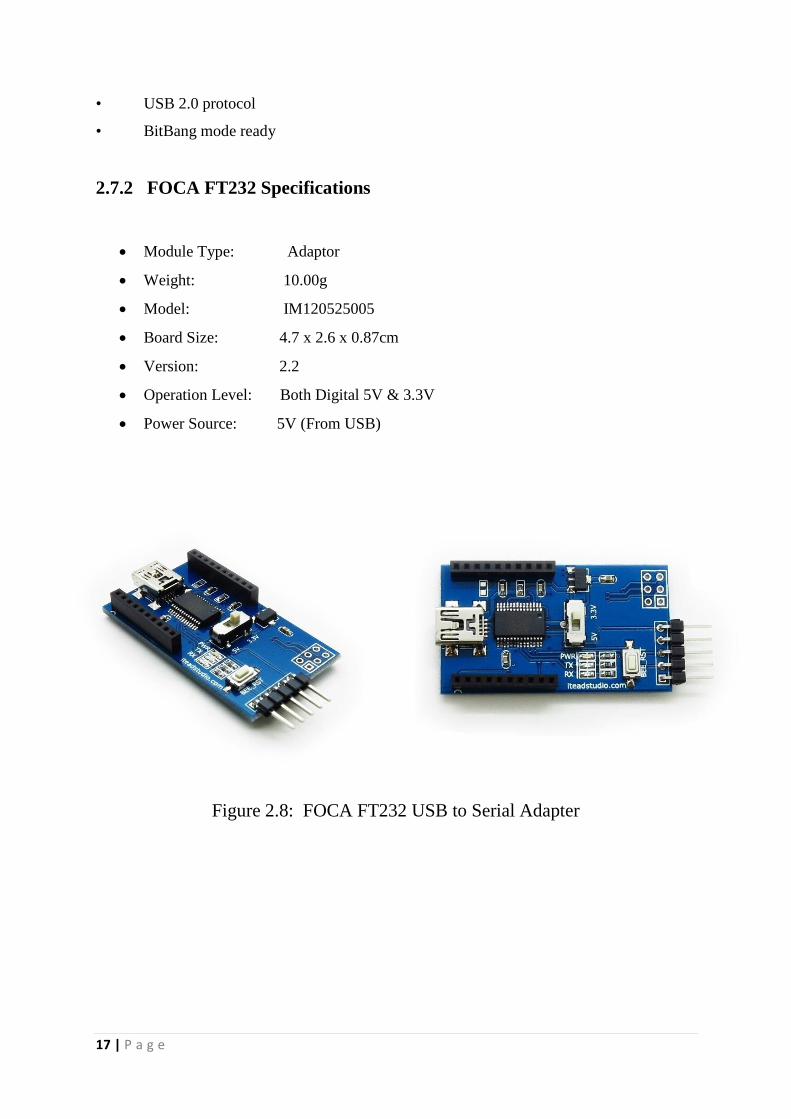
2.7 FOCA FT232 USB to Serial Adapter
USB to serial adapter with socket for xbee. It can be used for both programming and
communication purpose with the microcontroller. By help of the bee socket present in board
we can connect it from PC to XBEE modules for wireless applications. It is compatible with
all Arduino boards.It also has a USB serial adapter so that it can communicate to serial
devices with TTL/CMOS level.
2.7.1 FOCA FT232 Features
• Reset button for BEE modules
• 3.3V and 5V dual power output
• 3.3V and 5V IO compatible
17 | P a g e
• USB 2.0 protocol
• BitBang mode ready
2.7.2 FOCA FT232 Specifications
Module Type: Adaptor
Weight: 10.00g
Model: IM120525005
Board Size: 4.7 x 2.6 x 0.87cm
Version: 2.2
Operation Level: Both Digital 5V & 3.3V
Power Source: 5V (From USB)
Figure 2.8: FOCA FT232 USB to Serial Adapter
18 | P a g e
CHAPTER 3
Software Overview
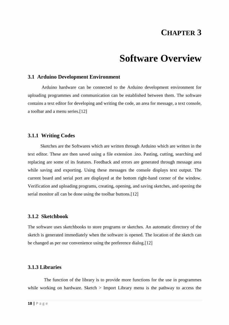
3.1 Arduino Development Environment
Arduino hardware can be connected to the Arduino development environment for
uploading programmes and communication can be established between them. The software
contains a text editor for developing and writing the code, an area for message, a text console,
a toolbar and a menu series.[12]
3.1.1 Writing Codes
Sketches are the Softwares which are written through Arduino which are written in the
text editor. These are then saved using a file extension .ino. Pasting, cutting, searching and
replacing are some of its features. Feedback and errors are generated through message area
while saving and exporting. Using these messages the console displays text output. The
current board and serial port are displayed at the bottom right-hand corner of the window.
Verification and uploading programs, creating, opening, and saving sketches, and opening the
serial monitor all can be done using the toolbar buttons.[12]
3.1.2 Sketchbook
The software uses sketchbooks to store programs or sketches. An automatic directory of the
sketch is generated immediately when the software is opened. The location of the sketch can
be changed as per our convenience using the preference dialog.[12]
3.1.3 Libraries
The function of the library is to provide more functions for the use in programmes
while working on hardware. Sketch > Import Library menu is the pathway to access the
19 | P a g e
library. One or more #include statements are inserted at the top of the sketch after which we
can compile our sketch. The sketch along with the library is loaded on the board which
consequently increases the amount of space than the normal space. If there is no use of the
library, the #include statement at the top of the code can be deleted to delete it.
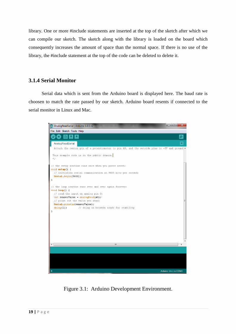
3.1.4 Serial Monitor
Serial data which is sent from the Arduino board is displayed here. The baud rate is
choosen to match the rate passed by our sketch. Arduino board resents if connected to the
serial monitor in Linux and Mac.
Figure 3.1: Arduino Development Environment.
20 | P a g e
3.2 Processing
It is a programming language by which visual arts and visual literacy have been
promoted since 2001.[13]
Listed below are some features of processing.
Free-ware
2D, 3D or PDF output interactive programs
OpenGL integration for accelerated 3D.
Can be run in almost all operating system
Provides more than 100 libraries
Presence of many many online articles and books make it well documented.
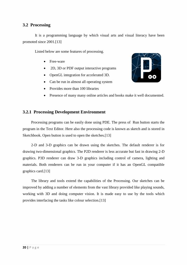
3.2.1 Processing Development Environment
Processing programs can be easily done using PDE. The press of Run button starts the
program in the Text Editor. Here also the processing code is known as sketch and is stored in
Sketchbook. Open button is used to open the sketches.[13]
2-D and 3-D graphics can be drawn using the sketches. The default renderer is for
drawing two-dimensional graphics. The P2D renderer is less accurate but fast in drawing 2-D
graphics. P3D renderer can draw 3-D graphics including control of camera, lighting and
materials. Both renderers can be run in your computer if it has an OpenGL compatible
graphics card.[13]
The library and tools extend the capabilities of the Processing. Our sketches can be
improved by adding a number of elements from the vast library provided like playing sounds,
working with 3D and doing computer vision. It is made easy to use by the tools which
provides interfacing the tasks like colour selection.[13]
21 | P a g e
Figure 3.2: Processing Development Environment.
3.2.2 G4P GUI Library
GUI for processing (G4P) is composed of rich 2D controls for GUI. Multiple window
support available with event handling system which is customizable. Use of double buffering
in controls may reduce the pressure on the processor but consumes more memory.
There are eight predefined colour schemes to give a consistent look and feel to the
controls. Copy & paste support added for “TextField” and “TextArea” controls by utilizing
the clipboard.
Event handling system is too simple and consistent. New event handlers can be
created by users for specific control(s).
22 | P a g e
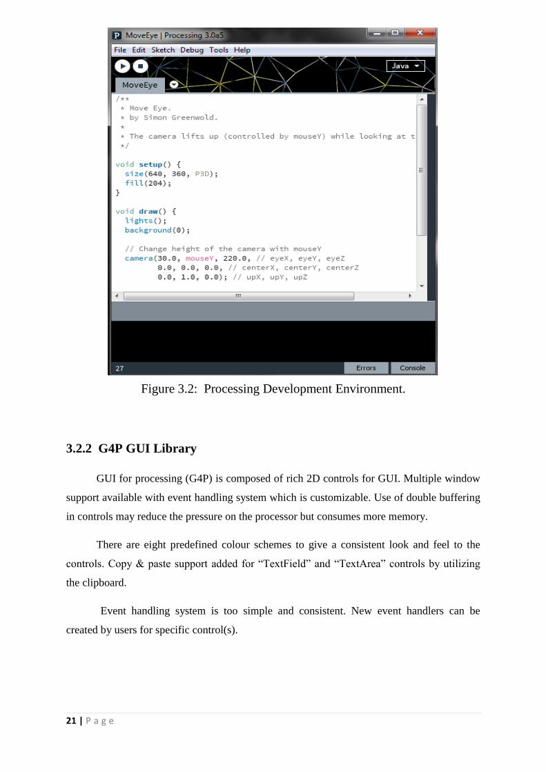
3.2.3 G4P GUI Builder Tool
This tool helps in quick creation & editing of user interfaces by providing a visual
environment. GUI can be created just by dragging the GUI controls from G4P library.[14]
Figure 3.3: GUI Builder Tool
GUI Builder Tool Features
Graphical interface
Position and size G4P controls for sketch.
Secondary windows can save the G4P controls.
Control properties can be edited in the properties option.
Tree view for easy navigation between controls.
Scrollable Sketch windows to easily create GUI.
Grid view for proper alignment of controls.
Design window auto hides when not in use.
Switching between processing window & design window is possible.
Code generation
It generates code for creating the GUI
It creates event handlers for each n every control in the GUI.
23 | P a g e
Codes written inside the even handlers are always saved.
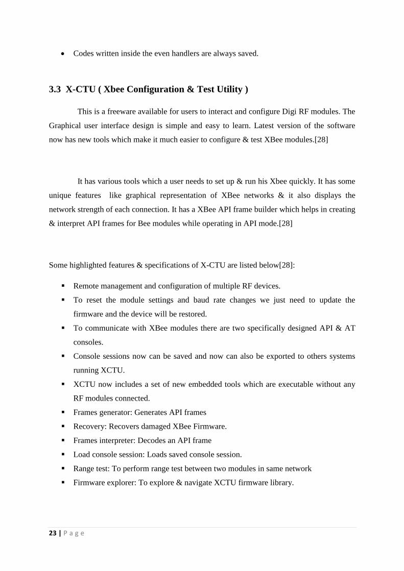
3.3 X-CTU ( Xbee Configuration & Test Utility )
This is a freeware available for users to interact and configure Digi RF modules. The
Graphical user interface design is simple and easy to learn. Latest version of the software
now has new tools which make it much easier to configure & test XBee modules.[28]
It has various tools which a user needs to set up & run his Xbee quickly. It has some
unique features like graphical representation of XBee networks & it also displays the
network strength of each connection. It has a XBee API frame builder which helps in creating
& interpret API frames for Bee modules while operating in API mode.[28]
Some highlighted features & specifications of X-CTU are listed below[28]:
Remote management and configuration of multiple RF devices.
To reset the module settings and baud rate changes we just need to update the
firmware and the device will be restored.
To communicate with XBee modules there are two specifically designed API & AT
consoles.
Console sessions now can be saved and now can also be exported to others systems
running XCTU.
XCTU now includes a set of new embedded tools which are executable without any
RF modules connected.
Frames generator: Generates API frames
Recovery: Recovers damaged XBee Firmware.
Frames interpreter: Decodes an API frame
Load console session: Loads saved console session.
Range test: To perform range test between two modules in same network
Firmware explorer: To explore & navigate XCTU firmware library.
24 | P a g e
Figure 3.4: X-CTU Configuration Window
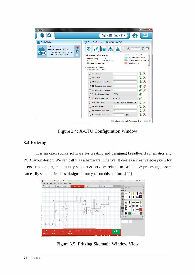
3.4 Fritzing
It is an open source software for creating and designing breadboard schematics and
PCB layout design. We can call it as a hardware initiative. It creates a creative ecosystem for
users. It has a large community support & services related to Arduino & processing. Users
can easily share their ideas, designs, prototypes on this platform.[29]
Figure 3.5: Fritzing Skematic Window View
25 | P a g e
CHAPTER 4
Hardware Implementation & Programming
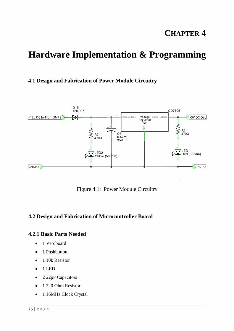
4.1 Design and Fabrication of Power Module Circuitry
Figure 4.1: Power Module Circuitry
4.2 Design and Fabrication of Microcontroller Board
4.2.1 Basic Parts Needed
1 Veroboard
1 Pushbutton
1 10k Resistor
1 LED
2 22pF Capacitors
1 220 Ohm Resistor
1 16MHz Clock Crystal
26 | P a g e
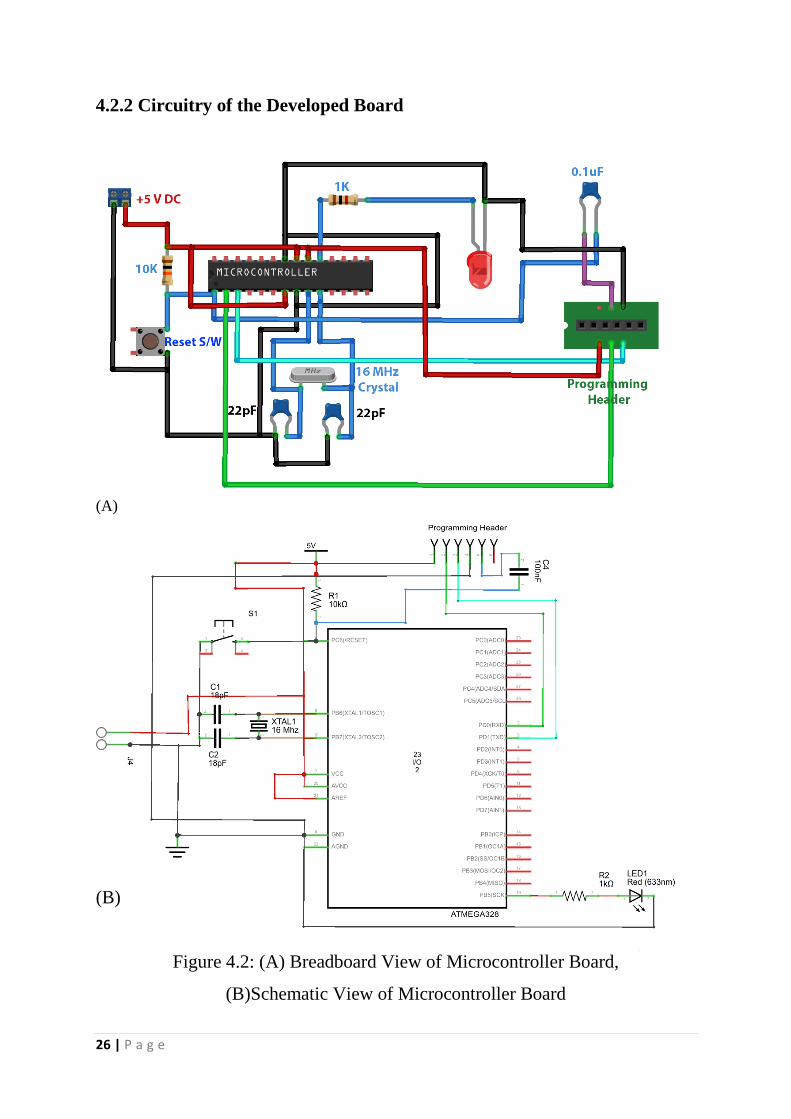
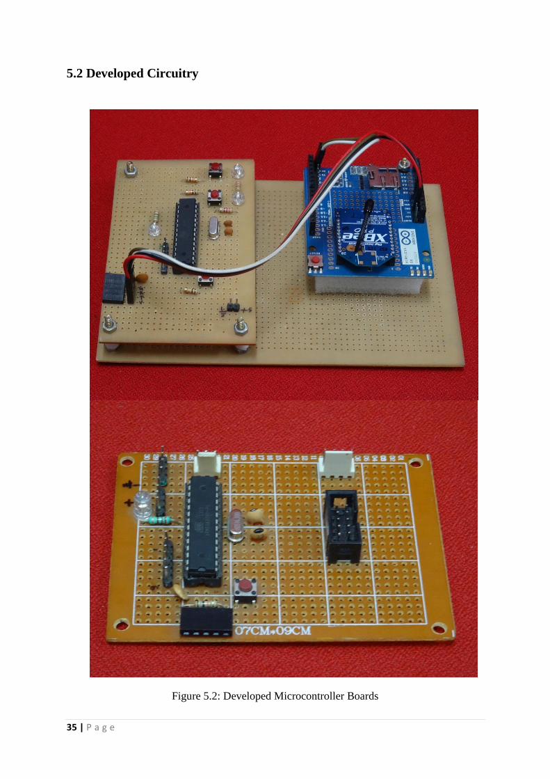
4.2.2 Circuitry of the Developed Board
(A)
(B)
Figure 4.2: (A) Breadboard View of Microcontroller Board,
(B)Schematic View of Microcontroller Board
27 | P a g e
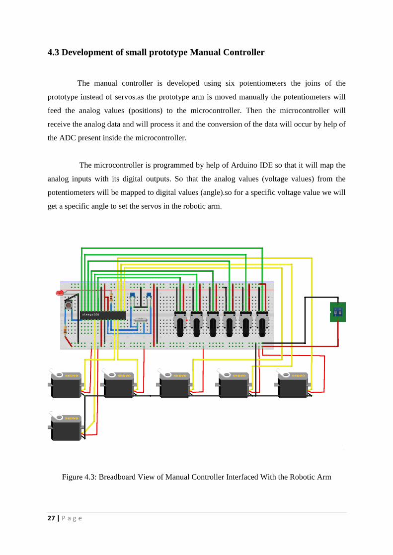
4.3 Development of small prototype Manual Controller
The manual controller is developed using six potentiometers the joins of the
prototype instead of servos.as the prototype arm is moved manually the potentiometers will
feed the analog values (positions) to the microcontroller. Then the microcontroller will
receive the analog data and will process it and the conversion of the data will occur by help of
the ADC present inside the microcontroller.
The microcontroller is programmed by help of Arduino IDE so that it will map the
analog inputs with its digital outputs. So that the analog values (voltage values) from the
potentiometers will be mapped to digital values (angle).so for a specific voltage value we will
get a specific angle to set the servos in the robotic arm.
Figure 4.3: Breadboard View of Manual Controller Interfaced With the Robotic Arm
28 | P a g e
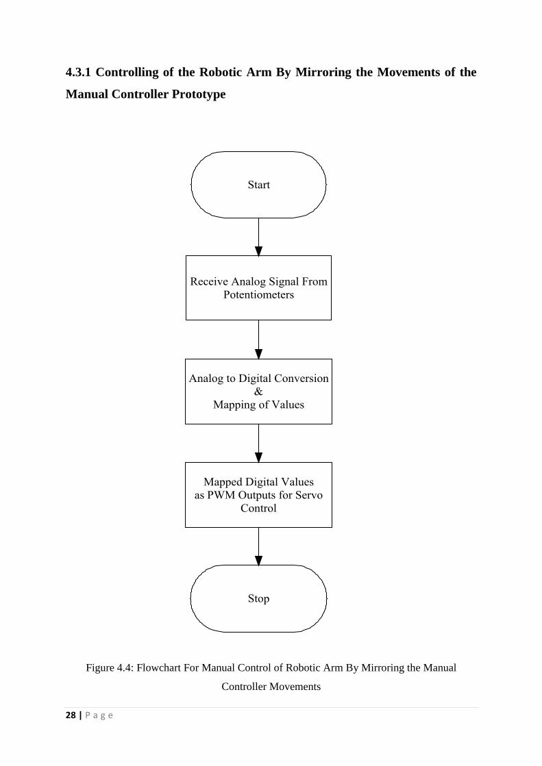
4.3.1 Controlling of the Robotic Arm By Mirroring the Movements of the
Manual Controller Prototype
Figure 4.4: Flowchart For Manual Control of Robotic Arm By Mirroring the Manual
Controller Movements
29 | P a g e
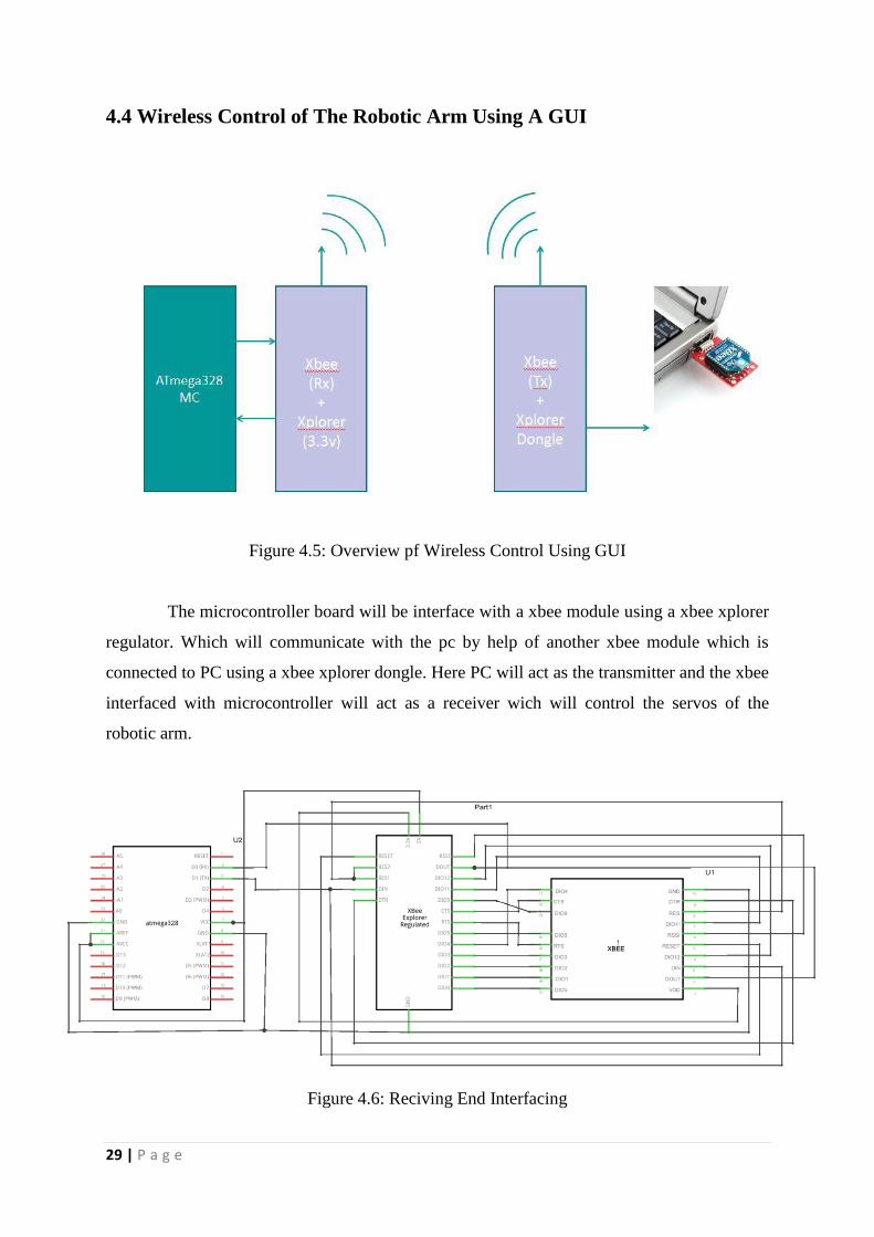
4.4 Wireless Control of The Robotic Arm Using A GUI
Figure 4.5: Overview pf Wireless Control Using GUI
The microcontroller board will be interface with a xbee module using a xbee xplorer
regulator. Which will communicate with the pc by help of another xbee module which is
connected to PC using a xbee xplorer dongle. Here PC will act as the transmitter and the xbee
interfaced with microcontroller will act as a receiver wich will control the servos of the
robotic arm.
Figure 4.6: Reciving End Interfacing
30 | P a g e
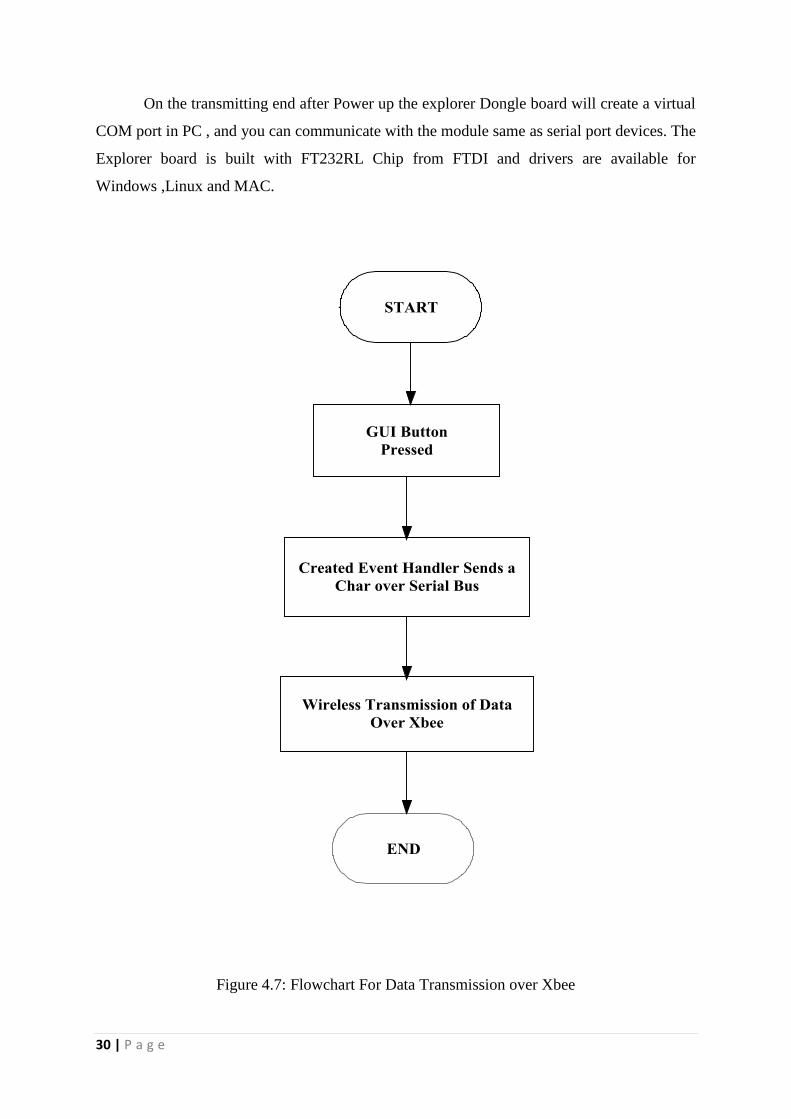
On the transmitting end after Power up the explorer Dongle board will create a virtual
COM port in PC , and you can communicate with the module same as serial port devices. The
Explorer board is built with FT232RL Chip from FTDI and drivers are available for
Windows ,Linux and MAC.
Figure 4.7: Flowchart For Data Transmission over Xbee
31 | P a g e
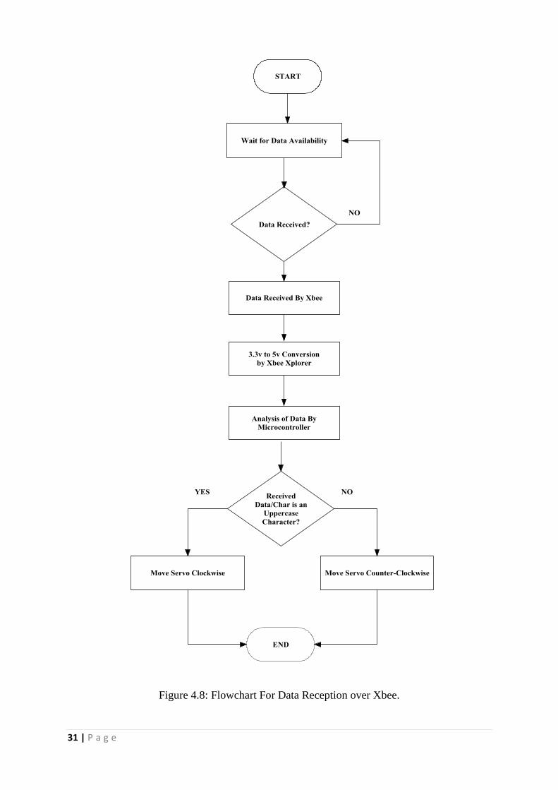
Figure 4.8: Flowchart For Data Reception over Xbee.
32 | P a g e
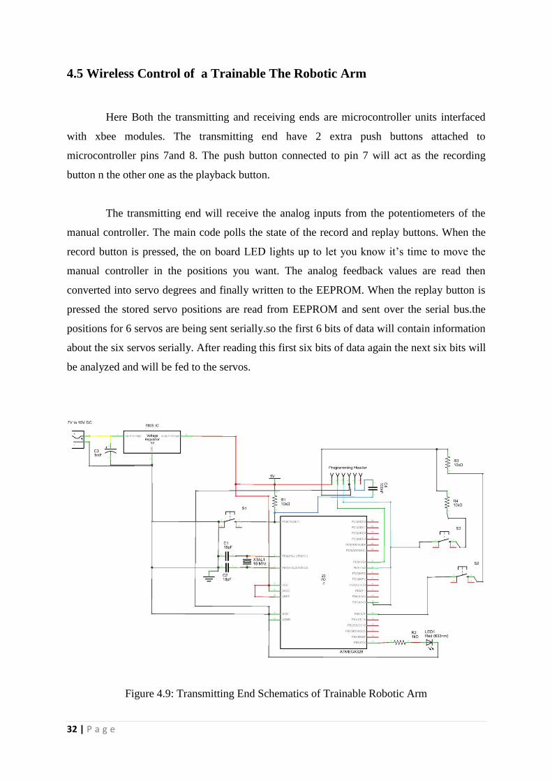
4.5 Wireless Control of a Trainable The Robotic Arm
Here Both the transmitting and receiving ends are microcontroller units interfaced
with xbee modules. The transmitting end have 2 extra push buttons attached to
microcontroller pins 7and 8. The push button connected to pin 7 will act as the recording
button n the other one as the playback button.
The transmitting end will receive the analog inputs from the potentiometers of the
manual controller. The main code polls the state of the record and replay buttons. When the
record button is pressed, the on board LED lights up to let you know it’s time to move the
manual controller in the positions you want. The analog feedback values are read then
converted into servo degrees and finally written to the EEPROM. When the replay button is
pressed the stored servo positions are read from EEPROM and sent over the serial bus.the
positions for 6 servos are being sent serially.so the first 6 bits of data will contain information
about the six servos serially. After reading this first six bits of data again the next six bits will
be analyzed and will be fed to the servos.
Figure 4.9: Transmitting End Schematics of Trainable Robotic Arm
33 | P a g e
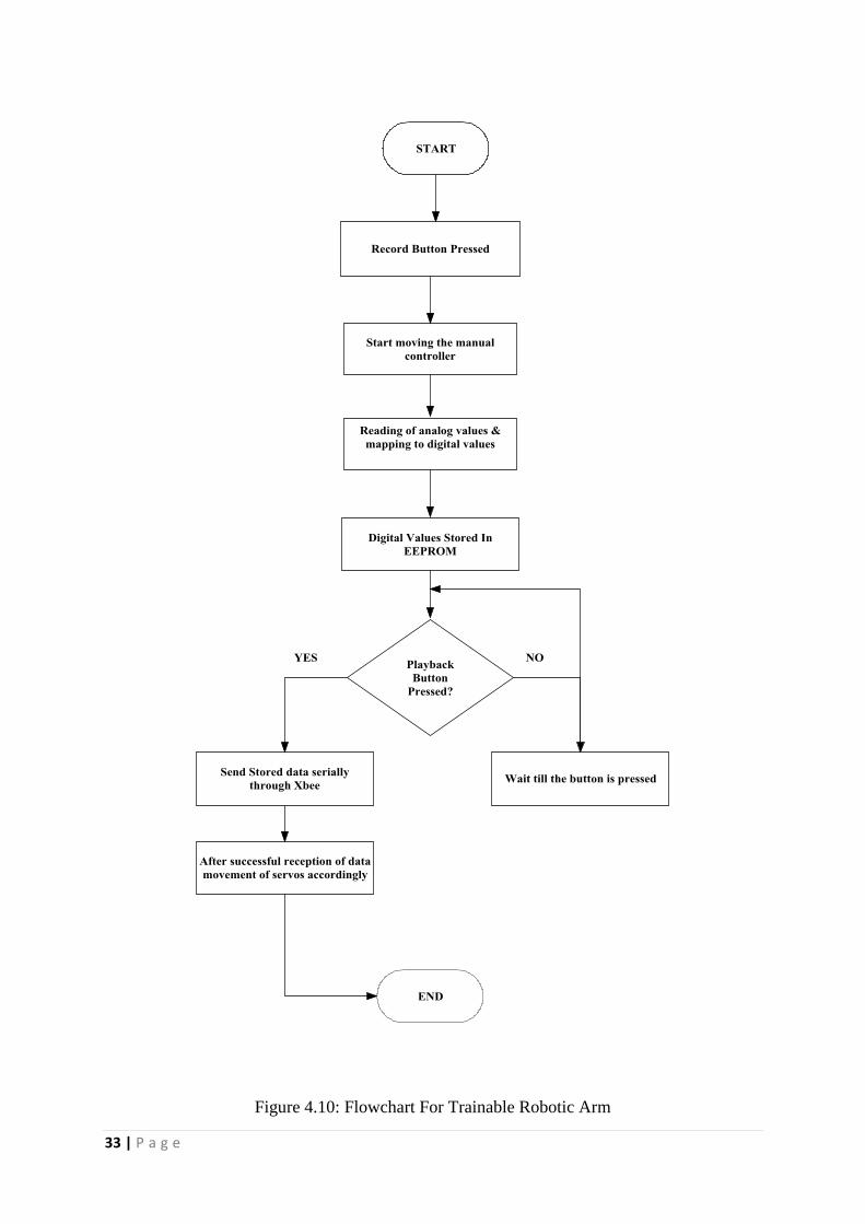
Figure 4.10: Flowchart For Trainable Robotic Arm
34 | P a g e
CHAPTER 5
Results and Discussions
In this section, the overall results for the project will be presented and explained. The
results include the actual structure, circuitry and programming source code.
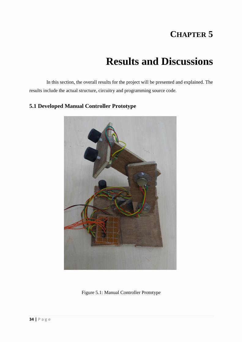
5.1 Developed Manual Controller Prototype
Figure 5.1: Manual Controller Prototype
35 | P a g e
5.2 Developed Circuitry
Figure 5.2: Developed Microcontroller Boards
36 | P a g e
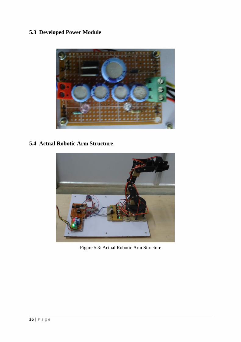
5.3 Developed Power Module
5.4 Actual Robotic Arm Structure
Figure 5.3: Actual Robotic Arm Structure
37 | P a g e
CHAPTER 6
Conclusion
6.1 Conclusion
In conclusion the objectives of this project are accomplished. A successful
development of a 4 degree freedom automated robotic arm having a 2 finger grip is done that
is faster in picking and placing. Skills to solve the problem were put to use to overcome any
hardware, software or circuitry problems that arise. The thesis provides analytical skills
training, hardware assembly training, program writing training and circuitry design training.
Generally, this project gives students a chance to incorporate robotic theories and
application into their projects. Future developments on projects related to the robotic studies
are a must to further enhance the robotic field in our country and bring the robotic field to a
whole new level internationally.
38 | P a g e
REFERENCES
[1] Mohamed Naufal, Omar. "Pick And Place Robotic Arm Controlled By Computer."
(2007).
[2] B Goldy Katal, Saahil Gupta, Shitij Kakkar. “Design And Operation Of
Synchronised Robotic Arm”, International Journal of Research in Engineering and
Technology, Volume: 02 Issue: 08 | Aug-2013.
[3] Khairul Afikh Bin Roslan, “Pick And Place Robotic Arm”, Thesis,. Submitted to
Universiti Teknikal Malaysia Melaka. May 2009
[4] Mohd Ashiq Kamaril Yusoffa, Reza Ezuan Saminb, Babul Salam Kader Ibrahimc,
“Wireless Mobile Robotic Arm”, Procedia Engineering Vol 41, pp 1072 – 1078 (2012).
[5] Jegede Olawale, Awodele Oludele, Ajayi Ayodele, “Development of a Microcontroller
Based Robotic Arm”, in Proceedings of the Computer Science and IT Education
Conference pg: 549-557. 2007
[6] Kuan Pei Wen, “PICK AND PLACE ROBOTIC ARM”, Under Graduate Project Paper
Submitted to Universiti Teknologi Malaysia. June 2012
[7] Brian W. Evans, “Arduino Programming Notebook”, Book, Published First Edition
2007.
[8] Alan G. Smith, “Introduction to Arduino- A Piece of Cake”, Book, Published, ISBN:
1463698348, ISBN-13: 978-1463698348, September 30, 2011
[9] Casey Reas, Ben Fry, “Processing A Programming Handbook”, Book, The MIT Press
Cambridge, Massachusetts,London, England. Published January 1, 2007,
[10] Dudek, Gregory, and Michael Jenkin. Computational principles of mobile robotics.
Cambridge university press, 2010.
[11] Svec, Robert. "Trainable Robotic Arm." Overview. Adafruit, n.d. Web.
[12] Arduino References, Online Contents,
http://www.arduino.cc/en/Main/Standalone
http://arduino.cc/en/guide/Environment,
http://arduino.cc/en/Main/ArduinoBoardDiecimila
[13] Processing References, Online Contents,
https://processing.org/
https://processing.org/reference/libraries/
39 | P a g e
[14] G4P tools : http://www.lagers.org.uk/g4p/index.html
[15] M. Varchola and M. Drutarovsky, "Zigbee based home automation wireless sensor
network," Acta Electrotechnica et Informatica, vol. 7, no. 4, pp. 1-8, 2007.
[16] M. Banzi, Getting Started with arduino. O'Reilly Media, Inc., 2009
[17] Atmel, "Atmega328p." Retrieved from http://www.atmel.com. 2014
[18] Arduino, "Introduction: Arduino Uno Overview." Retrieved from
arduino.cc/en/Main/ArduinoBoardUno, 2014
[19] M. Banzi, Getting Started with arduino. " O'Reilly Media, Inc.", 2009
[20] Quigley, Morgan, Alan Asbeck, and Andrew Ng. "A low-cost compliant 7-DOF
robotic manipulator." In Robotics and Automation (ICRA), 2011 IEEE International
Conference on, pp. 6051-6058. IEEE, 2011.
[21] Krishna, R., G. Sowmya Bala, S. Sastry ASC, B. Bhanu Prakash Sarma, and Gokul
Sai Alla. "Design and implementation of a robotic arm based on haptic technology." Int.
J. of Eng. Research and Applications 2, no. 34 (2012).
[22] Cheng, Heng-Tze, and Pei Zhang Zheng. "Real-Time Imitative Robotic Arm Control
for Home RobotApplications." (2011).
[23] Zhang, Yong, Brandon K. Chen, Xinyu Liu, and Yu Sun. "Autonomous robotic pick-
and-place of microobjects." Robotics, IEEE Transactions on 26, no. 1 (2010): 200-207.
[24] Clarke, William F., and Mark W. Handlesman. "Robotic end effector." U.S. Patent
4,657,470, issued April 14, 1987.
[25] K. F. Bhringer , R. S. Fearing and K. Y. Goldberg S. Y. Nof Handbook of Industrial
Robotics, pp.1045 -1066 1999 :Wiley
[26] Liu, Xia, Heping Chen, Mengliu Wang, and Shanshan Chen. "An XBee-Pro based
energy monitoring system." In Telecommunication Networks and Applications
Conference (ATNAC), 2012 Australasian, pp. 1-6. IEEE, 2012.
[27] Xbee modules references
http://www.rhydolabz.com/index.php?main_page=product_info&products_id=433,
http://www.rhydolabz.com/index.php?main_page=product_info&products_id=1093
[28] XCTU : http://www.digi.com/products/wireless-wired-embedded-solutions/zigbee-rf-
modules/xctu
[29] Fritzing Software, http://fritzing.org/home/