Embed Size (px)
Citation preview
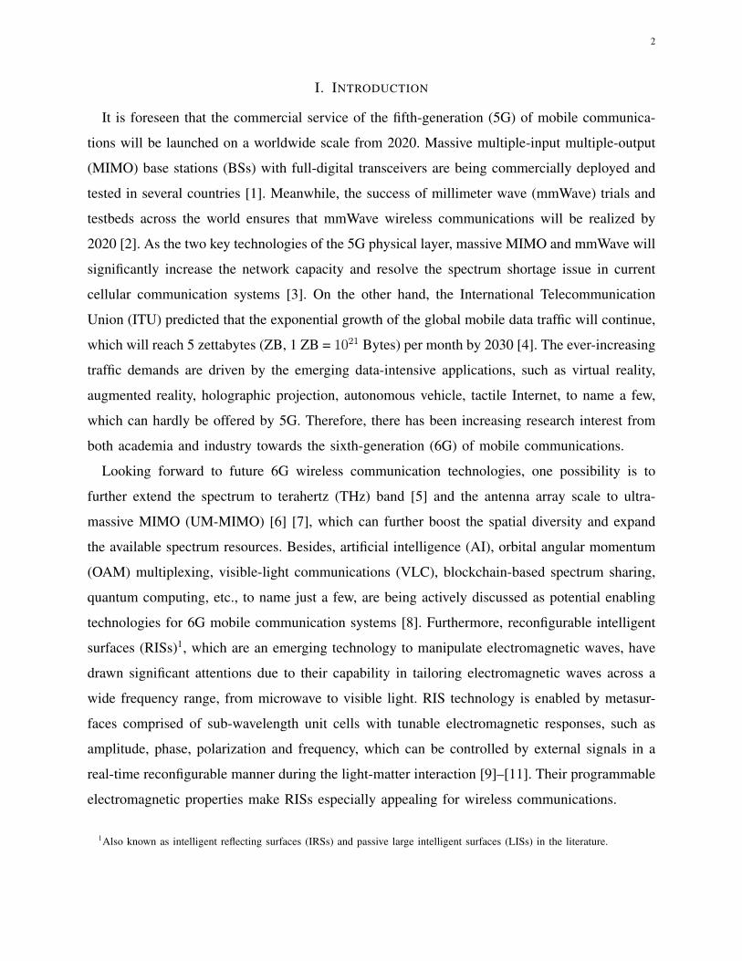
1
Wireless Communications with Reconfigurable
Intelligent Surface: Path Loss Modeling and
Experimental Measurement
Wankai Tang, Ming Zheng Chen, Xiangyu Chen, Jun Yan Dai, Yu Han,
Marco Di Renzo, Yong Zeng, Shi Jin, Qiang Cheng, and Tie Jun Cui
Abstract
Reconfigurable intelligent surfaces (RISs) comprised of tunable unit cells have recently drawn
significant attentions due to their superior capability in manipulating electromagnetic waves. In partic-
ular, RIS-assisted wireless communications have the great potential to achieve significant performance
improvement and coverage enhancement in a cost-effective and energy-efficient manner, by properly
programming the reflection coefficients of the unit cells of RISs. In this paper, the free-space path loss
models of RIS-assisted wireless communications are developed for different scenarios by studying the
physics and electromagnetic nature of RISs. The proposed models, which are first validated through
extensive simulation results, reveal the relationships between the free-space path loss of RIS-assisted
wireless communications and the distances from the transmitter/receiver to the RIS, the size of the
RIS, the near-field/far-field effects of the RIS, and the radiation patterns of antennas and unit cells.
In addition, three fabricated RISs (metasurfaces) are utilized to further corroborate theoretical findings
through experimental measurements conducted in a microwave anechoic chamber. The measurement
results match well with the modeling results, thus validating the proposed free-space path loss models
for RIS, which may pave the way for further theoretical studies and practical applications in this field.
Index TermsPath loss, reconfigurable intelligent surface, metasurface, intelligent reflecting surface, large intel-
ligent surface, wireless propagation measurements.
W. Tang, X. Chen, Y. Han, Y. Zeng, and S. Jin are with the National Mobile Communications Research Laboratory, Southeast
University, Nanjing, China.
M. Z. Chen, J. Y. Dai, Q. Cheng, and T. J. Cui are with the State Key Laboratory of Millimeter Waves, Southeast University,
Nanjing, China.
M. Di Renzo is with Paris-Saclay University (L2S - CNRS, CentraleSupelec, University Paris Sud), Paris, France.
arX
iv:1
911.
0532
6v1
[ee
ss.S
P] 1
3 N
ov 2
019
2
I. INTRODUCTION
It is foreseen that the commercial service of the fifth-generation (5G) of mobile communica-
tions will be launched on a worldwide scale from 2020. Massive multiple-input multiple-output
(MIMO) base stations (BSs) with full-digital transceivers are being commercially deployed and
tested in several countries [1]. Meanwhile, the success of millimeter wave (mmWave) trials and
testbeds across the world ensures that mmWave wireless communications will be realized by
2020 [2]. As the two key technologies of the 5G physical layer, massive MIMO and mmWave will
significantly increase the network capacity and resolve the spectrum shortage issue in current
cellular communication systems [3]. On the other hand, the International Telecommunication
Union (ITU) predicted that the exponential growth of the global mobile data traffic will continue,
which will reach 5 zettabytes (ZB, 1 ZB = 1021 Bytes) per month by 2030 [4]. The ever-increasing
traffic demands are driven by the emerging data-intensive applications, such as virtual reality,
augmented reality, holographic projection, autonomous vehicle, tactile Internet, to name a few,
which can hardly be offered by 5G. Therefore, there has been increasing research interest from
both academia and industry towards the sixth-generation (6G) of mobile communications.
Looking forward to future 6G wireless communication technologies, one possibility is to
further extend the spectrum to terahertz (THz) band [5] and the antenna array scale to ultra-
massive MIMO (UM-MIMO) [6] [7], which can further boost the spatial diversity and expand
the available spectrum resources. Besides, artificial intelligence (AI), orbital angular momentum
(OAM) multiplexing, visible-light communications (VLC), blockchain-based spectrum sharing,
quantum computing, etc., to name just a few, are being actively discussed as potential enabling
technologies for 6G mobile communication systems [8]. Furthermore, reconfigurable intelligent
surfaces (RISs)1, which are an emerging technology to manipulate electromagnetic waves, have
drawn significant attentions due to their capability in tailoring electromagnetic waves across a
wide frequency range, from microwave to visible light. RIS technology is enabled by metasur-
faces comprised of sub-wavelength unit cells with tunable electromagnetic responses, such as
amplitude, phase, polarization and frequency, which can be controlled by external signals in a
real-time reconfigurable manner during the light-matter interaction [9]–[11]. Their programmable
electromagnetic properties make RISs especially appealing for wireless communications.
1Also known as intelligent reflecting surfaces (IRSs) and passive large intelligent surfaces (LISs) in the literature.
3
Recently, we have witnessed fast growing research effort on wireless communication using
RISs. RISs have been utilized to realize new wireless transceiver architectures in [12]–[15], which
may bring a paradigm-shift on the transceiver design and reduce the hardware cost of future
wireless communication systems. Moreover, RISs can artificially reshape the electromagnetic
wave propagation environment [16]. In current wireless communication systems, the wireless en-
vironment, i.e., the physical objects that influence the propagation of the electromagnetic waves,
is uncontrollable. During the research and design processes of wireless communication systems,
one can only design transceivers, signal processing algorithms, and transmission protocols to
adapt to the radio environment. RISs, on the other hand, may in principle make the wireless
environment controllable and programmable, thus bringing unprecedented new opportunities for
enhancing the performance of wireless communication systems [17] [18].
Against this background, various RIS-assisted wireless communication systems have recently
been studied, by providing cost-effective and energy-efficient solutions that offer performance
improvements and coverage enhancement in wireless networks. [19]. For example, [20] showed
that, by jointly optimizing active and passive beamforming in an RIS-assisted wireless network,
the energy consumption and the coverage performance can be significantly improved. The joint
beamforming design was also investigated for improving the physical layer security [21] [22].
The authors of [23]–[25] optimized the achievable rate of RIS-assisted systems in different com-
munication scenarios. The energy efficiency of RIS-based downlink multi-user MISO systems
was maximized in [26] [27]. Energy harvesting performance, ergodic spectral efficiency, symbol
error probability, and outage probability of RIS-assisted wireless communications were derived
and optimized in [28]–[31]. The comparison with relays was carried out in [32]. The impact of
hardware imperfections, like discrete phase-shift and phase-dependent amplitude, were studied
in [29] [33] [34].
However, the major limitation of existing research on RIS-assisted wireless communications
is the lack of tractable and reliable physical and electromagnetic models for the RISs. Most of
the existing research works are based on simplistic mathematical models that regard the RIS as
a diagonal matrix with phase shift values. The responses of the RISs to the radio waves have not
yet been extensively studied from the physics and electromagnetic point of view, which may lead
to relatively simplified algorithm designs and performance predictions. To the best of the authors’
knowledge, in particular, there is no experimentally validated path loss model for RIS-assisted
wireless communications, even in the simple free-space propagation environment. The path loss
4
models used in most existing works do not consider physical factors such as the size of the RISs,
and the near-field/far-field effects of the RISs. Therefore, channel measurements are urgently
needed, which may provide authentic information on the path loss of RIS-assisted wireless
communications for researchers working in this emerging research field. Motivated by these
conditions, we develop the free-space path loss models of RIS-assisted wireless communications
in different scenarios based on the physics and electromagnetic nature of the RISs. We validate
them by using numerical simulations, and we also conduct the channel measurements through
fabricated RISs in an anechoic chamber to practically corroborate our findings. In particular, our
main contributions are summarized as follows:
1) We introduce a system model for RIS-assisted wireless communications from the perspective
of electromagnetic theory, which takes into account important physical factors like the physical
dimension of the RISs, and the radiation pattern of the unit cells. A general formula is derived
to characterize the free-space path loss of RIS-assisted wireless communications.
2) Based on the derived general formula, we propose three free-space path loss models for
RIS-assisted wireless communications, which capture three relevant scenarios and unveil the rela-
tionships between the free-space path loss of RIS and the distances from the transmitter/receiver
to the RIS, the size of the RIS, the near-field/far-field effects of the RIS, as well as the radiation
patterns of antennas and unit cells.
3) We report the world’s first experimental results that assess and validate the path loss of
RIS-assisted wireless communications. Three different RISs (metasurfaces) of various size are
utilized in the measurements. The measurement results are shown to be in good agreement with
the modeling results. Besides, the power consumption of the RISs and the effect of the incident
angle are also measured and discussed.
II. PRELIMINARIES
This section reviews several basic concepts, which will be used in the free-space path loss
modeling of RIS-assisted wireless communications in the next section.
A. Far Field and Near Field
The far field and near field are two different regions of the electromagnetic (EM) field around
an antenna or antenna array. When a transmitter is sufficiently far away from an antenna array,
the spherical wave generated by the transmitter can be approximately regarded as a plane wave
5
at the antenna array side. Specifically, when the maximum phase difference of the received signal
on the antenna array does not exceed π8, the transmitter is in the far field of the antenna array
[35]. Based on this assumption, the boundary of the far field and the near field2 of the antenna
array is defined as L = 2D2
λ, where L, D and λ denote the distance between the transmitter
and the center of the antenna array, the largest dimension of the antenna array and the wave
length of the signal, respectively [35]. It’s worth noting that when the transmitter is replaced
by a receiver, the above definition remains the same due to the reciprocity of the antenna array.
We will use the same definition of the far field and near field for the RIS in the next section.
When the distance between the transmitter/receiver and the center of the RIS is less than 2D2
λ,
the transmitter/receiver is considered to be in the near field of the RIS. Otherwise, they are in
the far field of the RIS.
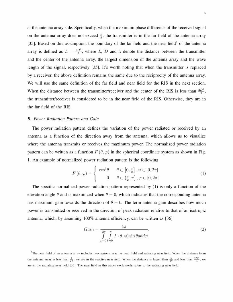
B. Power Radiation Pattern and Gain
The power radiation pattern defines the variation of the power radiated or received by an
antenna as a function of the direction away from the antenna, which allows us to visualize
where the antenna transmits or receives the maximum power. The normalized power radiation
pattern can be written as a function F (θ, ϕ) in the spherical coordinate system as shown in Fig.
1. An example of normalized power radiation pattern is the following
F (θ, ϕ) =
cos3θ θ ∈[0, π
2
], ϕ ∈ [0, 2π]
0 θ ∈(π2, π], ϕ ∈ [0, 2π]
(1)
The specific normalized power radiation pattern represented by (1) is only a function of the
elevation angle θ and is maximized when θ = 0, which indicates that the corresponding antenna
has maximum gain towards the direction of θ = 0. The term antenna gain describes how much
power is transmitted or received in the direction of peak radiation relative to that of an isotropic
antenna, which, by assuming 100% antenna efficiency, can be written as [36]
Gain =4π
2π∫ϕ=0
π∫θ=0
F (θ, ϕ) sin θdθdϕ
. (2)
2The near field of an antenna array includes two regions: reactive near field and radiating near field. When the distance from
the antenna array is less than λ2π
, we are in the reactive near field. When the distance is larger than λ2π
and less than 2D2
λ, we
are in the radiating near field [35]. The near field in this paper exclusively refers to the radiating near field.
6
Consider the antenna with power radiation pattern described by (1) as an example, its gain is
equal to 8 (9.03 dBi) under the assumption of 100% radiation efficiency, which means that the
power transmitted or received in the direction of peak radiation (θ = 0) is 9.03 dB higher than
that of an isotropic antenna. In the next section, we will use the definition of normalized power
radiation pattern not only for the antennas of the transmitter and receiver, but also for the unit
cells of the RIS in the free-space path loss modeling of RIS-assisted wireless communications.
𝜑
𝜃1
𝐹 𝜃, 𝜑
Fig. 1. Diagram of normalized power radiation pattern.
III. FREE-SPACE PATH LOSS MODELING OF RIS-ASSISTED WIRELESS COMMUNICATIONS
In this section, we describe the overall system model and develop the free-space path loss
model for RIS-assisted wireless communications in different scenarios.
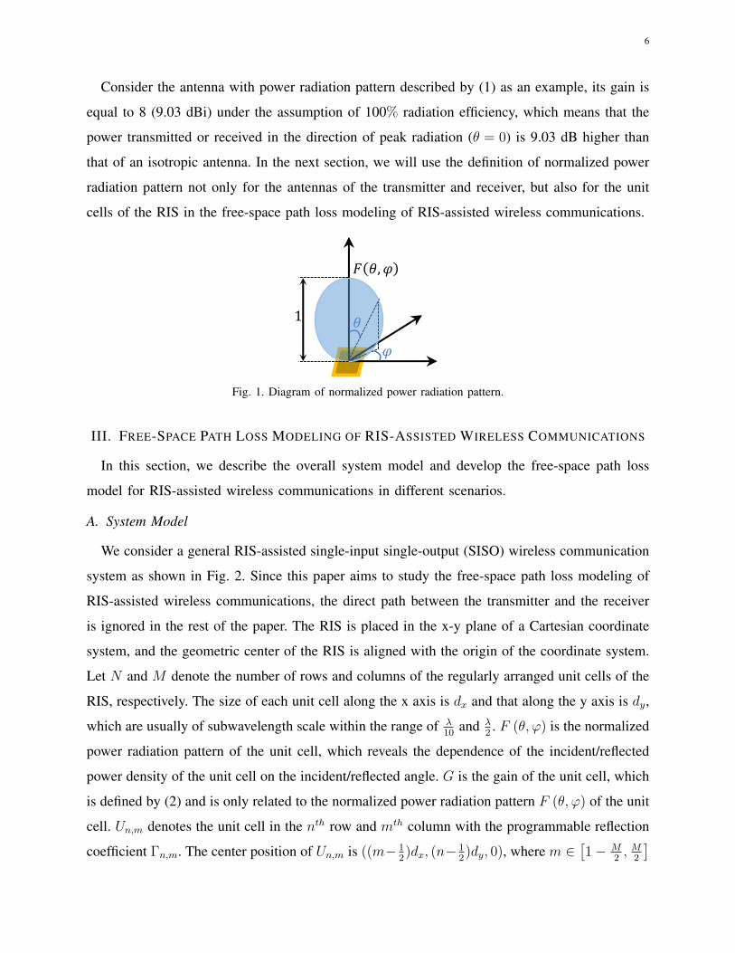
A. System Model
We consider a general RIS-assisted single-input single-output (SISO) wireless communication
system as shown in Fig. 2. Since this paper aims to study the free-space path loss modeling of
RIS-assisted wireless communications, the direct path between the transmitter and the receiver
is ignored in the rest of the paper. The RIS is placed in the x-y plane of a Cartesian coordinate
system, and the geometric center of the RIS is aligned with the origin of the coordinate system.
Let N and M denote the number of rows and columns of the regularly arranged unit cells of the
RIS, respectively. The size of each unit cell along the x axis is dx and that along the y axis is dy,
which are usually of subwavelength scale within the range of λ10
and λ2. F (θ, ϕ) is the normalized
power radiation pattern of the unit cell, which reveals the dependence of the incident/reflected
power density of the unit cell on the incident/reflected angle. G is the gain of the unit cell, which
is defined by (2) and is only related to the normalized power radiation pattern F (θ, ϕ) of the unit
cell. Un,m denotes the unit cell in the nth row and mth column with the programmable reflection
coefficient Γn,m. The center position of Un,m is ((m− 12)dx, (n− 1
2)dy, 0), where m ∈
[1− M
2, M
2
]
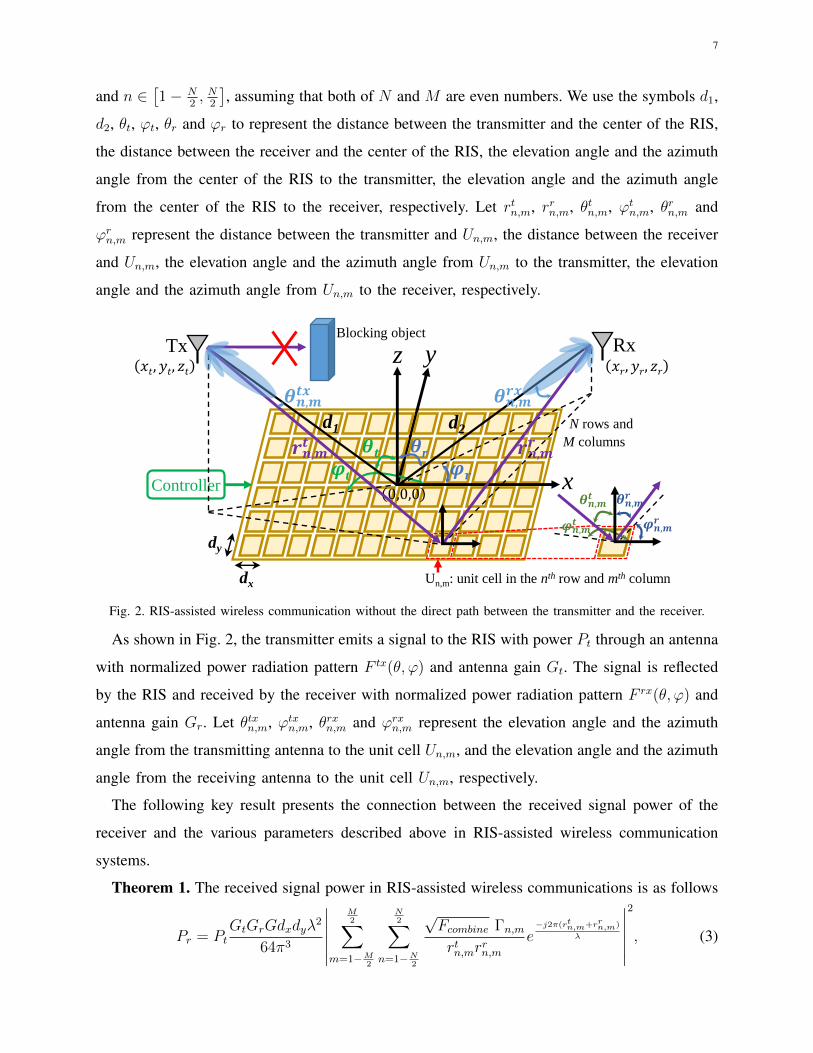
7
and n ∈[1− N
2, N
2
], assuming that both of N and M are even numbers. We use the symbols d1,
d2, θt, ϕt, θr and ϕr to represent the distance between the transmitter and the center of the RIS,
the distance between the receiver and the center of the RIS, the elevation angle and the azimuth
angle from the center of the RIS to the transmitter, the elevation angle and the azimuth angle
from the center of the RIS to the receiver, respectively. Let rtn,m, rrn,m, θtn,m, ϕtn,m, θrn,m and
ϕrn,m represent the distance between the transmitter and Un,m, the distance between the receiver
and Un,m, the elevation angle and the azimuth angle from Un,m to the transmitter, the elevation
angle and the azimuth angle from Un,m to the receiver, respectively.
Un,m: unit cell in the nth row and mth column
Controller
N rows and
M columns
x
yz
d1 d2
Tx Rx
𝒓𝒏,𝒎𝒕 𝒓𝒏,𝒎
𝒓
dx
dy
𝝋𝒓
𝜽r
0,0,0
𝑥𝑡, 𝑦𝑡, 𝑧𝑡 𝑥𝑟, 𝑦𝑟, 𝑧𝑟
𝜽𝒕
𝝋t
𝜽𝒏,𝒎𝒕𝒙 𝜽𝒏,𝒎
𝒓𝒙
Blocking object
𝜽𝒏,𝒎𝒕
𝝋𝒏,𝒎𝒓𝝋𝒏,𝒎
𝒕
𝜽𝒏,𝒎𝒓
Fig. 2. RIS-assisted wireless communication without the direct path between the transmitter and the receiver.
As shown in Fig. 2, the transmitter emits a signal to the RIS with power Pt through an antenna
with normalized power radiation pattern F tx(θ, ϕ) and antenna gain Gt. The signal is reflected
by the RIS and received by the receiver with normalized power radiation pattern F rx(θ, ϕ) and
antenna gain Gr. Let θtxn,m, ϕtxn,m, θrxn,m and ϕrxn,m represent the elevation angle and the azimuth
angle from the transmitting antenna to the unit cell Un,m, and the elevation angle and the azimuth
angle from the receiving antenna to the unit cell Un,m, respectively.
The following key result presents the connection between the received signal power of the
receiver and the various parameters described above in RIS-assisted wireless communication
systems.
Theorem 1. The received signal power in RIS-assisted wireless communications is as follows
Pr = PtGtGrGdxdyλ
2
64π3
∣∣∣∣∣∣M2∑
m=1−M2
N2∑
n=1−N2
√Fcombine Γn,mrtn,mr
rn,m
e−j2π(rtn,m+rrn,m)
λ
∣∣∣∣∣∣2
, (3)
8
where Fcombine=F tx(θtxn,m, ϕ
txn,m
)F(θtn,m, ϕ
tn,m
)F(θrn,m, ϕ
rn,m
)F rx
(θrxn,m, ϕ
rxn,m
), which accounts
for the effect of the normalized power radiation patterns on the received signal power.
Proof : See Appendix A.
Theorem 1 reveals that the received signal power is proportional to the transmitted signal
power, the gains of the transmitting/receiving antennas, the gain of the unit cell, the size of the
unit cell, the square of the wave length. In addition, Theorem 1 also indicates that the received
signal power is related to the normalized power radiation patterns of the transmitting/receiving
antennas and unit cells, the reflection coefficients of the unit cells, and the distances between
the transmitter/receiver and the unit cells. However, their specific relationships are not that
straightforward, which needs further analysis and discussions in the rest of this paper. Theorem
1 also shows that the RIS-assisted wireless communication systems are transmitter-receiver
reciprocal, since the same signal power can be received if the roles of the transmitter and the
receiver are exchanged, which is an especially important property in the uplink and downlink
design of time division duplexing (TDD) wireless communication systems.
Controller
RIS
BS
Blocking object User
User
move
(a)
RIS
User1
User2
Usern
Controller
BS
Blocking object
(b)
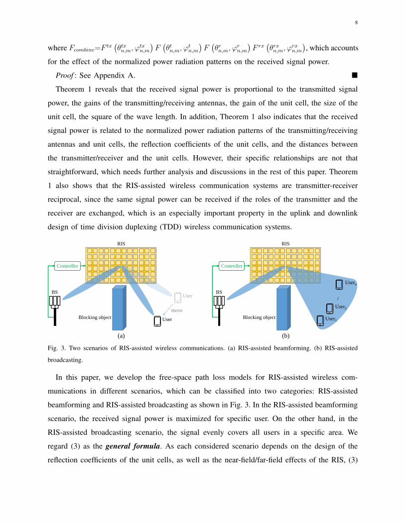
Fig. 3. Two scenarios of RIS-assisted wireless communications. (a) RIS-assisted beamforming. (b) RIS-assisted
broadcasting.
In this paper, we develop the free-space path loss models for RIS-assisted wireless com-
munications in different scenarios, which can be classified into two categories: RIS-assisted
beamforming and RIS-assisted broadcasting as shown in Fig. 3. In the RIS-assisted beamforming
scenario, the received signal power is maximized for specific user. On the other hand, in the
RIS-assisted broadcasting scenario, the signal evenly covers all users in a specific area. We
regard (3) as the general formula. As each considered scenario depends on the design of the
reflection coefficients of the unit cells, as well as the near-field/far-field effects of the RIS, (3)
9
will be further discussed in different cases to draw more insights on the free-space path loss of
RIS-assisted wireless communications.
B. Far Field Beamforming Case
The signals reflected by all the unit cells of RIS to the receiver can be aligned in phase
to enhance the received signal power, which makes RIS especially appealing for beamforming
applications. Therefore, it is important to study the free-space path loss in the RIS-assisted
beamforming scenario. The case where both of the transmitter and receiver are in the far field
of the RIS is first discussed as follows.
Proposition 1. Assume that the directions of peak radiation of both the transmitting and
receiving antennas point to the center of the RIS, and all the unit cells of the RIS share the
same reflection coefficient Γn,m = Aejφ. The received signal power in the far field case can be
written as
Pr =PtGtGrGM
2N2dxdyλ2F (θt, ϕt)F (θr, ϕr)A
2
64π3d12d2
2
×
∣∣∣∣∣sinc(Mπλ
(sin θt cosϕt+ sin θr cosϕr)dx)
sinc(πλ(sin θt cosϕt+ sin θr cosϕr)dx)
sinc(Nπλ
(sin θt sinϕt+ sin θr sinϕr)dy)
sinc(πλ(sin θt sinϕt+ sin θr sinϕr)dy
) ∣∣∣∣∣2
.
(4)
If θr = θt and ϕr = ϕt + π, (4) is maximized as
Pmaxr =
GtGrGM2N2dxdyλ
2F (θt, ϕt)F (θr, ϕr)A2
64π3d12d2
2 Pt. (5)
The path loss corresponding to (5) is
PLbeamfarfield =64π3(d1d2)2
GtGrGM2N2dxdyλ2F (θt, ϕt)F (θr, ϕr)A2. (6)
Proof : See Appendix B.
Proposition 1 is more insightful compared with the general formula (3) in Theorem 1 and
equation (4) is referred to as the far-field formula. Proposition 1 reveals that the free-space
path loss of RIS-assisted wireless communications is proportional to (d1d2)2 in the far field
case. The free-space path loss is also related to the unit cells’ normalized power radiation
pattern F (θ, ϕ), which is fixed once the RIS is designed and fabricated. Furthermore, when the
reflection coefficients of all the unit cells are the same, the RIS performs specular reflection, that
is, the incident signal is mainly reflected towards the mirror direction (θr = θt and ϕr = ϕt+π).
10
The above analysis assumes that all the unit cells share the same reflection coefficient. The
design of Γn,m is discussed in the following proposition, which enables the RIS to beamform the
reflected signal to the receiver in any desired direction (θdes, ϕdes) through intelligent reflection3.
Proposition 2. Assume that the directions of peak radiation of both the transmitting and
receiving antennas point to the center of the RIS, and the reflection coefficients of all the unit
cells share the same amplitude value A and different phase shift φn,m (Γn,m = Aejφn,m). The
received signal power through intelligent reflection in the far field case can be written as
Pr =PtGtGrGM
2N2dxdyλ2F (θt, ϕt)F (θr, ϕr)A
2
64π3d12d2
2
×
∣∣∣∣∣sinc(Mπλ
(sin θt cosϕt+ sin θr cosϕr+δ1)dx)
sinc(πλ(sin θt cosϕt+ sin θr cosϕr+δ1)dx)
sinc(Nπλ
(sin θt sinϕt+ sin θr sinϕr+δ2)dy)
sinc(πλ(sin θt sinϕt+ sin θr sinϕr+δ2)dy
) ∣∣∣∣∣2
,
(7)
where δ1
(m−1
2
)dx+δ2
(n−1
2
)dy=
λφn,m2π
.
When θr = θdes and ϕr = ϕdes as desired, (7) is maximized as
Pmaxr = Pt
GtGrGM2N2dxdyλ
2F (θt, ϕt)F (θdes, ϕdes)A2
64π3d12d2
2 , (8)
when δ1 = − sin θt cosϕt − sin θdes cosϕdes and δ2 = − sin θt sinϕt − sin θdes sinϕdes. The
corresponding design of φn,m is
φn,m = mod (2π
λ(δ1
(m−1
2
)dx+δ2
(n−1
2
)dy), 2π)
= mod (−2π
λ((sin θt cosϕt+ sin θdes cosϕdes)
(m−1
2
)dx+
(sin θt sinϕt+ sin θdes sinϕdes)
(n−1
2
)dy), 2π).
(9)
Proof : See Appendix B.
According to the phase shift design described by (9) of Proposition 2, the incident signal
from direction (θt, ϕt) to the RIS can be manipulated to reflect towards any desired direction
(θdes, ϕdes) in the far field case, which is referred to as intelligent reflection. Besides, (4) and (7)
also indicate that the free-space path loss of RIS-assisted wireless communication has the same
scaling law for specular reflection and intelligent reflection in the far-field beamforming case.3The intelligent reflection here refers to intelligently controlling the reflection nature of the RIS by properly programming the
reflection coefficients of the unit cells of the RIS.
11
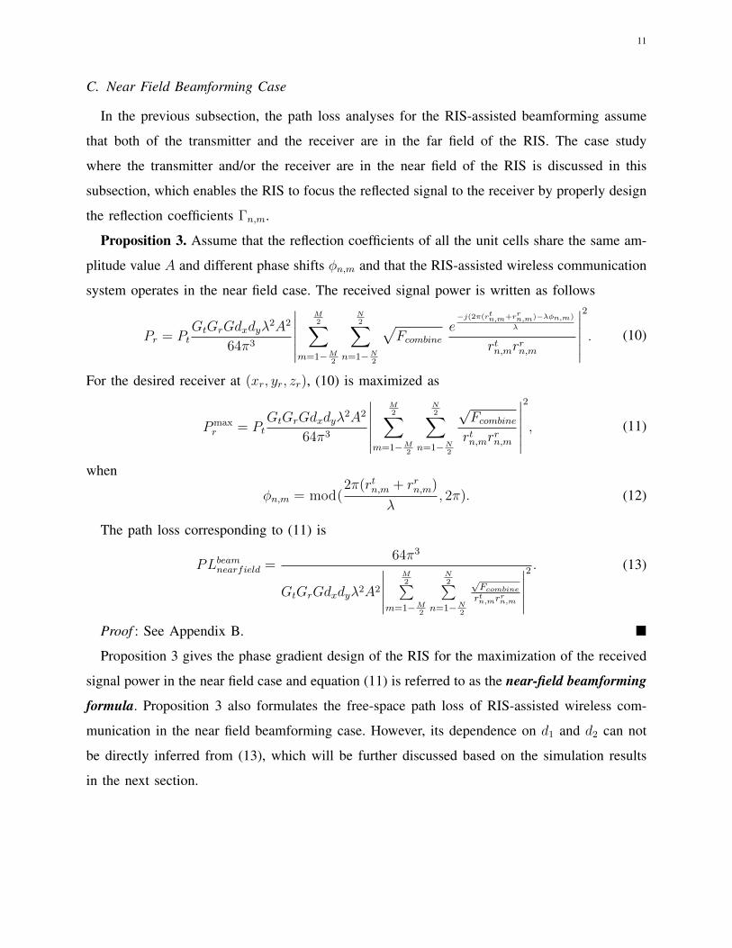
C. Near Field Beamforming Case
In the previous subsection, the path loss analyses for the RIS-assisted beamforming assume
that both of the transmitter and the receiver are in the far field of the RIS. The case study
where the transmitter and/or the receiver are in the near field of the RIS is discussed in this
subsection, which enables the RIS to focus the reflected signal to the receiver by properly design
the reflection coefficients Γn,m.
Proposition 3. Assume that the reflection coefficients of all the unit cells share the same am-
plitude value A and different phase shifts φn,m and that the RIS-assisted wireless communication
system operates in the near field case. The received signal power is written as follows
Pr = PtGtGrGdxdyλ
2A2
64π3
∣∣∣∣∣∣M2∑
m=1−M2
N2∑
n=1−N2
√Fcombine
e−j(2π(rtn,m+rrn,m)−λφn,m)
λ
rtn,mrrn,m
∣∣∣∣∣∣2
. (10)
For the desired receiver at (xr, yr, zr), (10) is maximized as
Pmaxr = Pt
GtGrGdxdyλ2A2
64π3
∣∣∣∣∣∣M2∑
m=1−M2
N2∑
n=1−N2
√Fcombinertn,mr
rn,m
∣∣∣∣∣∣2
, (11)
when
φn,m = mod(2π(rtn,m + rrn,m)
λ, 2π). (12)
The path loss corresponding to (11) is
PLbeamnearfield =64π3
GtGrGdxdyλ2A2
∣∣∣∣∣M2∑
m=1−M2
N2∑
n=1−N2
√Fcombinertn,mr
rn,m
∣∣∣∣∣2 . (13)
Proof : See Appendix B.
Proposition 3 gives the phase gradient design of the RIS for the maximization of the received
signal power in the near field case and equation (11) is referred to as the near-field beamforming
formula. Proposition 3 also formulates the free-space path loss of RIS-assisted wireless com-
munication in the near field beamforming case. However, its dependence on d1 and d2 can not
be directly inferred from (13), which will be further discussed based on the simulation results
in the next section.
12
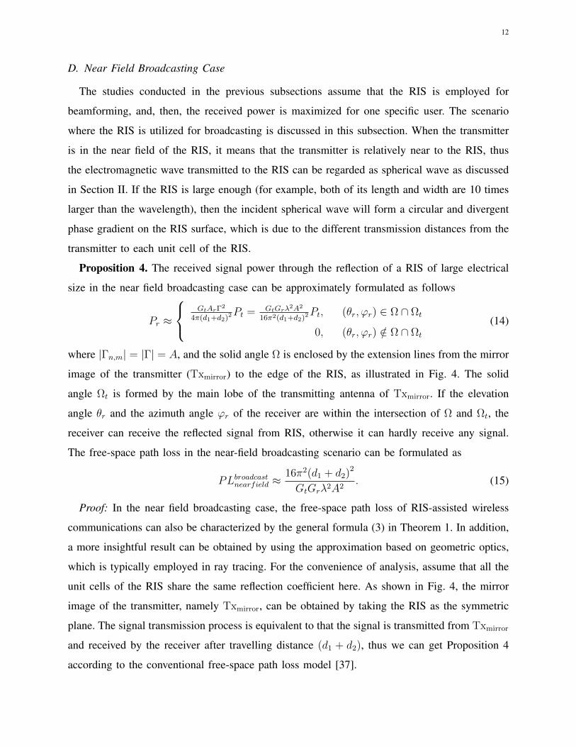
D. Near Field Broadcasting Case
The studies conducted in the previous subsections assume that the RIS is employed for
beamforming, and, then, the received power is maximized for one specific user. The scenario
where the RIS is utilized for broadcasting is discussed in this subsection. When the transmitter
is in the near field of the RIS, it means that the transmitter is relatively near to the RIS, thus
the electromagnetic wave transmitted to the RIS can be regarded as spherical wave as discussed
in Section II. If the RIS is large enough (for example, both of its length and width are 10 times
larger than the wavelength), then the incident spherical wave will form a circular and divergent
phase gradient on the RIS surface, which is due to the different transmission distances from the
transmitter to each unit cell of the RIS.
Proposition 4. The received signal power through the reflection of a RIS of large electrical
size in the near field broadcasting case can be approximately formulated as follows
Pr ≈
GtArΓ2
4π(d1+d2)2Pt = GtGrλ2A2
16π2(d1+d2)2Pt, (θr, ϕr) ∈ Ω ∩ Ωt
0, (θr, ϕr) /∈ Ω ∩ Ωt
(14)
where |Γn,m| = |Γ| = A, and the solid angle Ω is enclosed by the extension lines from the mirror
image of the transmitter (Txmirror) to the edge of the RIS, as illustrated in Fig. 4. The solid
angle Ωt is formed by the main lobe of the transmitting antenna of Txmirror. If the elevation
angle θr and the azimuth angle ϕr of the receiver are within the intersection of Ω and Ωt, the
receiver can receive the reflected signal from RIS, otherwise it can hardly receive any signal.
The free-space path loss in the near-field broadcasting scenario can be formulated as
PLbroadcastnearfield ≈16π2(d1 + d2)2
GtGrλ2A2. (15)
Proof: In the near field broadcasting case, the free-space path loss of RIS-assisted wireless
communications can also be characterized by the general formula (3) in Theorem 1. In addition,
a more insightful result can be obtained by using the approximation based on geometric optics,
which is typically employed in ray tracing. For the convenience of analysis, assume that all the
unit cells of the RIS share the same reflection coefficient here. As shown in Fig. 4, the mirror
image of the transmitter, namely Txmirror, can be obtained by taking the RIS as the symmetric
plane. The signal transmission process is equivalent to that the signal is transmitted from Txmirror
and received by the receiver after travelling distance (d1 + d2), thus we can get Proposition 4
according to the conventional free-space path loss model [37].
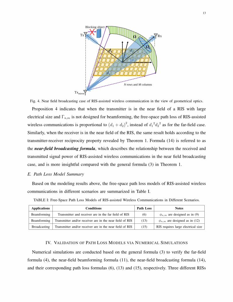
13
N rows and M columns
d1
d2
Tx Rx
Txmirror
d1
𝝋𝒓
𝜽r
Blocking object
Ωt
Ω
Fig. 4. Near field broadcasting case of RIS-assisted wireless communication in the view of geometrical optics.
Proposition 4 indicates that when the transmitter is in the near field of a RIS with large
electrical size and Γn,m is not designed for beamforming, the free-space path loss of RIS-assisted
wireless communications is proportional to (d1 + d2)2, instead of d12d2
2 as for the far-field case.
Similarly, when the receiver is in the near field of the RIS, the same result holds according to the
transmitter-receiver reciprocity property revealed by Theorem 1. Formula (14) is referred to as
the near-field broadcasting formula, which describes the relationship between the received and
transmitted signal power of RIS-assisted wireless communications in the near field broadcasting
case, and is more insightful compared with the general formula (3) in Theorem 1.
E. Path Loss Model Summary
Based on the modeling results above, the free-space path loss models of RIS-assisted wireless
communications in different scenarios are summarized in Table I.
TABLE I: Free-Space Path Loss Models of RIS-assisted Wireless Communications in Different Scenarios.
Applications Conditions Path Loss Notes
Beamforming Transmitter and receiver are in the far field of RIS (6) φn,m are designed as in (9)
Beamforming Transmitter and/or receiver are in the near field of RIS (13) φn,m are designed as in (12)
Broadcasting Transmitter and/or receiver are in the near field of RIS (15) RIS requires large electrical size
IV. VALIDATION OF PATH LOSS MODELS VIA NUMERICAL SIMULATIONS
Numerical simulations are conducted based on the general formula (3) to verify the far-field
formula (4), the near-field beamforming formula (11), the near-field broadcasting formula (14),
and their corresponding path loss formulas (6), (13) and (15), respectively. Three different RISs
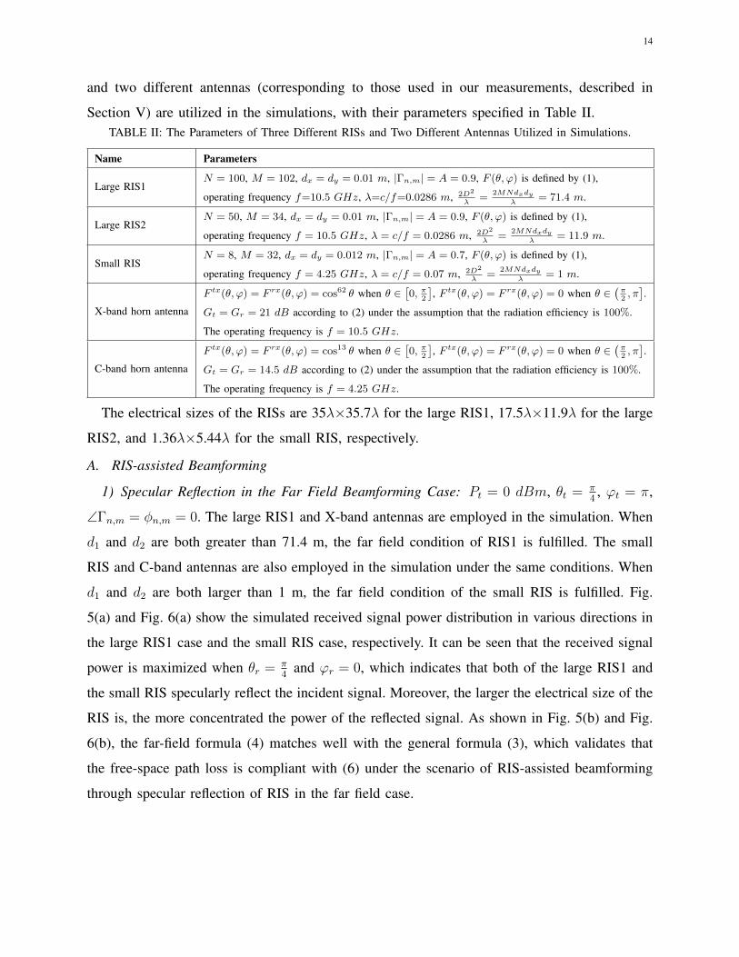
14
and two different antennas (corresponding to those used in our measurements, described in
Section V) are utilized in the simulations, with their parameters specified in Table II.TABLE II: The Parameters of Three Different RISs and Two Different Antennas Utilized in Simulations.
Name Parameters
Large RIS1N = 100, M = 102, dx = dy = 0.01 m, |Γn,m| = A = 0.9, F (θ, ϕ) is defined by (1),
operating frequency f=10.5 GHz, λ=c/f=0.0286 m, 2D2
λ=
2MNdxdyλ
= 71.4 m.
Large RIS2N = 50, M = 34, dx = dy = 0.01 m, |Γn,m| = A = 0.9, F (θ, ϕ) is defined by (1),
operating frequency f = 10.5 GHz, λ = c/f = 0.0286 m, 2D2
λ=
2MNdxdyλ
= 11.9 m.
Small RISN = 8, M = 32, dx = dy = 0.012 m, |Γn,m| = A = 0.7, F (θ, ϕ) is defined by (1),
operating frequency f = 4.25 GHz, λ = c/f = 0.07 m, 2D2
λ=
2MNdxdyλ
= 1 m.
X-band horn antenna
F tx(θ, ϕ) = F rx(θ, ϕ) = cos62 θ when θ ∈[0, π
2
], F tx(θ, ϕ) = F rx(θ, ϕ) = 0 when θ ∈
(π2, π
].
Gt = Gr = 21 dB according to (2) under the assumption that the radiation efficiency is 100%.
The operating frequency is f = 10.5 GHz.
C-band horn antenna
F tx(θ, ϕ) = F rx(θ, ϕ) = cos13 θ when θ ∈[0, π
2
], F tx(θ, ϕ) = F rx(θ, ϕ) = 0 when θ ∈
(π2, π
].
Gt = Gr = 14.5 dB according to (2) under the assumption that the radiation efficiency is 100%.
The operating frequency is f = 4.25 GHz.
The electrical sizes of the RISs are 35λ×35.7λ for the large RIS1, 17.5λ×11.9λ for the large
RIS2, and 1.36λ×5.44λ for the small RIS, respectively.
A. RIS-assisted Beamforming
1) Specular Reflection in the Far Field Beamforming Case: Pt = 0 dBm, θt = π4, ϕt = π,
∠Γn,m = φn,m = 0. The large RIS1 and X-band antennas are employed in the simulation. When
d1 and d2 are both greater than 71.4 m, the far field condition of RIS1 is fulfilled. The small
RIS and C-band antennas are also employed in the simulation under the same conditions. When
d1 and d2 are both larger than 1 m, the far field condition of the small RIS is fulfilled. Fig.
5(a) and Fig. 6(a) show the simulated received signal power distribution in various directions in
the large RIS1 case and the small RIS case, respectively. It can be seen that the received signal
power is maximized when θr = π4
and ϕr = 0, which indicates that both of the large RIS1 and
the small RIS specularly reflect the incident signal. Moreover, the larger the electrical size of the
RIS is, the more concentrated the power of the reflected signal. As shown in Fig. 5(b) and Fig.
6(b), the far-field formula (4) matches well with the general formula (3), which validates that
the free-space path loss is compliant with (6) under the scenario of RIS-assisted beamforming
through specular reflection of RIS in the far field case.

15
φr=0
φr=π/2
φr=3π/2
φr=π
φr=π/4
φr=7π/4φr=5π/4
φr=3π/4
θr=π/6 θr=π/3
(θr=π/4, φr=0)
(a)
dBm
100 150 200 250 300
d2 (m)
-85
-80
-75
-70
-65
-60
-55
-50
rr=
0 (
dBm
) general formula (d1=100m)
far-field formula (d1=100m)
general formula (d1=200m)
far-field formula (d1=200m)
general formula (d1=350m)
far-field formula (d1=350m)
(b)Fig. 5. Simulation results of RIS-assisted beamforming through specular reflection of large RIS1 in the far field
case. (a) Received signal power distribution when d1 = d2 = 100 m. (b) Received signal power in the specular
direction versus d1 and d2.
φr=0
φr=π/2
φr=3π/2
φr=π
φr=π/4
φr=7π/4φr=5π/4
φr=3π/4
θr=π/6
θr=π/3
(θr=π/4, φr=0)
(a)
dBm
2 4 6 8 10 12 14 16 18 20
d2 (m)
-60
-55
-50
-45
-40
-35
-30
-25
-20
-15
rr=
0 (
dBm
) general formula (d1=1m)
far-field formula (d1=1m)
general formula (d1=2m)
far-field formula (d1=2m)
general formula (d1=3.5m)
far-field formula (d1=3.5m)
(b)Fig. 6. Simulation results of RIS-assisted beamforming through specular reflection of small RIS in the far field
case. (a) Received signal power distribution when d1 = 3.5 m and d2 = 10 m. (b) Received signal power in the
specular direction versus d1 and d2.
2) Intelligent Reflection in the Far Field Beamforming Case: Pt = 0 dBm, θt = π4, ϕt = π.
The large RIS1 and X-band antennas are employed in the simulation, and the phase shifts φn,m
are designed to steer the reflected signal to a desired direction of θdes = π3
and ϕdes = 7π4
according to (9). The small RIS and C-band antennas are also employed in the simulation, and
φn,m are designed to steer the reflected signal to a desired direction of θdes = π6
and ϕdes = 0.
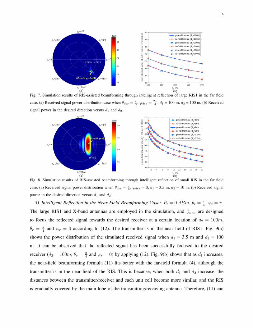
Fig. 7(a) and Fig. 8(a) show that the received signal power is maximized when θr = π3, ϕr = 7π
4
and θr = π6, ϕr = 0, respectively, which indicates that both of the large RIS1 and the small
RIS successfully reflect the incident signal to the desired direction. As shown in Fig. 7(b) and
Fig. 8(b), the far-field formula (7) with phase design matches well with the general formula (3),
which validates that the free-space path loss adheres to (6) under the scenario of RIS-assisted
beamforming through intelligent reflection of RIS in the far field case.
16
φr=0
φr=π/2
φr=3π/2
φr=π
φr=π/4
φr=7π/4φr=5π/4
φr=3π/4
θr=π/6 θr=π/3
(θr=π/3, φr=7π/4)
(a)
dBm
100 150 200 250 300
d2 (m)
-90
-85
-80
-75
-70
-65
-60
-55
rr
general formula (d1=100m)
far-field formula (d1=100m)
general formula (d1=200m)
far-field formula (d1=200m)
general formula (d1=350m)
far-field formula (d1=350m)
(b)Fig. 7. Simulation results of RIS-assisted beamforming through intelligent reflection of large RIS1 in the far field
case. (a) Received signal power distribution case when θdes = π3 , ϕdes = 7π
4 , d1 = 100 m, d2 = 100 m. (b) Received
signal power in the desired direction versus d1 and d2.
φr=0
φr=π/2
φr=3π/2
φr=π
φr=π/4
φr=7π/4φr=5π/4
φr=3π/4
(θr=π/6, φr=0)
(a)
θr=π/6
θr=π/3
dBm
2 4 6 8 10 12 14 16 18 20
d2 (m)
-60
-55
-50
-45
-40
-35
-30
-25
-20
-15
rr=
0 (
dBm
) general formula (d1=1m)
far-field formula (d1=1m)
general formula (d1=2m)
far-field formula (d1=2m)
general formula (d1=3.5m)
far-field formula (d1=3.5m)
(b)Fig. 8. Simulation results of RIS-assisted beamforming through intelligent reflection of small RIS in the far field
case. (a) Received signal power distribution when θdes = π6 , ϕdes = 0, d1 = 3.5 m, d2 = 10 m. (b) Received signal
power in the desired direction versus d1 and d2.
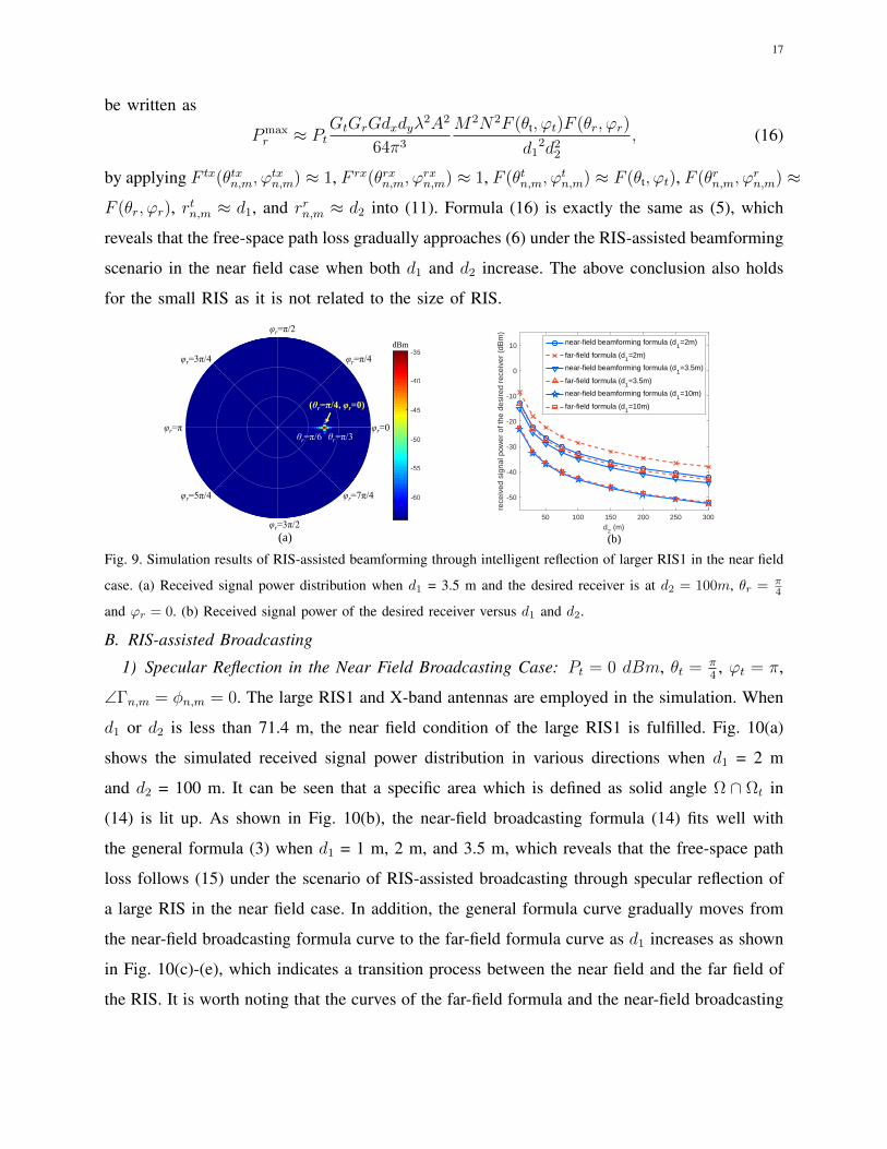
3) Intelligent Reflection in the Near Field Beamforming Case: Pt = 0 dBm, θt = π4, ϕt = π.
The large RIS1 and X-band antennas are employed in the simulation, and φn,m are designed
to focus the reflected signal towards the desired receiver at a certain location of d2 = 100m,
θr = π4
and ϕr = 0 according to (12). The transmitter is in the near field of RIS1. Fig. 9(a)
shows the power distribution of the simulated received signal when d1 = 3.5 m and d2 = 100
m. It can be observed that the reflected signal has been successfully focused to the desired
receiver (d2 = 100m, θr = π4
and ϕr = 0) by applying (12). Fig. 9(b) shows that as d1 increases,
the near-field beamforming formula (11) fits better with the far-field formula (4), although the
transmitter is in the near field of the RIS. This is because, when both d1 and d2 increase, the
distances between the transmitter/receiver and each unit cell become more similar, and the RIS
is gradually covered by the main lobe of the transmitting/receiving antenna. Therefore, (11) can
17
be written as
Pmaxr ≈ Pt
GtGrGdxdyλ2A2
64π3
M2N2F (θt, ϕt)F (θr, ϕr)
d12d2
2
, (16)
by applying F tx(θtxn,m, ϕtxn,m) ≈ 1, F rx(θrxn,m, ϕ
rxn,m) ≈ 1, F (θtn,m, ϕ
tn,m) ≈ F (θt, ϕt), F (θrn,m, ϕ
rn,m) ≈
F (θr, ϕr), rtn,m ≈ d1, and rrn,m ≈ d2 into (11). Formula (16) is exactly the same as (5), which
reveals that the free-space path loss gradually approaches (6) under the RIS-assisted beamforming
scenario in the near field case when both d1 and d2 increase. The above conclusion also holds
for the small RIS as it is not related to the size of RIS.
dBm
φr=0
φr=π/2
φr=3π/2
φr=π
φr=π/4
φr=7π/4φr=5π/4
φr=3π/4
θr=π/6 θr=π/3
(θr=π/4, φr=0)
(a)
50 100 150 200 250 300
d2 (m)
-50
-40
-30
-20
-10
0
10
rece
ived
sig
nal p
ower
of t
he d
esire
d re
ceiv
er (
dBm
)
near-field beamforming formula (d1=2m)
far-field formula (d1=2m)
near-field beamforming formula (d1=3.5m)
far-field formula (d1=3.5m)
near-field beamforming formula (d1=10m)
far-field formula (d1=10m)
(b)
Fig. 9. Simulation results of RIS-assisted beamforming through intelligent reflection of larger RIS1 in the near field
case. (a) Received signal power distribution when d1 = 3.5 m and the desired receiver is at d2 = 100m, θr = π4
and ϕr = 0. (b) Received signal power of the desired receiver versus d1 and d2.
B. RIS-assisted Broadcasting
1) Specular Reflection in the Near Field Broadcasting Case: Pt = 0 dBm, θt = π4, ϕt = π,
∠Γn,m = φn,m = 0. The large RIS1 and X-band antennas are employed in the simulation. When
d1 or d2 is less than 71.4 m, the near field condition of the large RIS1 is fulfilled. Fig. 10(a)
shows the simulated received signal power distribution in various directions when d1 = 2 m
and d2 = 100 m. It can be seen that a specific area which is defined as solid angle Ω ∩ Ωt in
(14) is lit up. As shown in Fig. 10(b), the near-field broadcasting formula (14) fits well with
the general formula (3) when d1 = 1 m, 2 m, and 3.5 m, which reveals that the free-space path
loss follows (15) under the scenario of RIS-assisted broadcasting through specular reflection of
a large RIS in the near field case. In addition, the general formula curve gradually moves from
the near-field broadcasting formula curve to the far-field formula curve as d1 increases as shown
in Fig. 10(c)-(e), which indicates a transition process between the near field and the far field of
the RIS. It is worth noting that the curves of the far-field formula and the near-field broadcasting
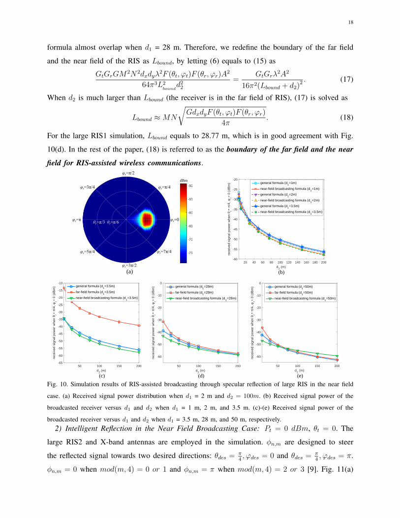
18
formula almost overlap when d1 = 28 m. Therefore, we redefine the boundary of the far field
and the near field of the RIS as Lbound, by letting (6) equals to (15) as
GtGrGM2N2dxdyλ
2F (θt, ϕt)F (θr, ϕr)A2
64π3L2bound
d22
=GtGrλ
2A2
16π2(Lbound + d2)2 . (17)
When d2 is much larger than Lbound (the receiver is in the far field of RIS), (17) is solved as
Lbound ≈MN
√GdxdyF (θt, ϕt)F (θr, ϕr)
4π. (18)
For the large RIS1 simulation, Lbound equals to 28.77 m, which is in good agreement with Fig.
10(d). In the rest of the paper, (18) is referred to as the boundary of the far field and the near
field for RIS-assisted wireless communications.
φr=0
φr=π/2
φr=3π/2
φr=π
φr=π/4
φr=7π/4φr=5π/4
φr=3π/4
θr=π/6θr=π/3
(a)
dBm
20 40 60 80 100 120 140 160 180 200
d2 (m)
-60
-55
-50
-45
-40
-35
-30
-25
-20
rr=
0 (
dBm
) general formula (d1=1m)
near-field broadcasting formula (d1=1m)
general formula (d1=2m)
near-field broadcasting formula (d1=2m)
general formula (d1=3.5m)
near-field broadcasting formula (d1=3.5m)
(b)
50 100 150 200
d2 (m)
-65
-60
-55
-50
-45
-40
-35
-30
-25
-20
-15
-10
rr=
0 (
dBm
) general formula (d1=3.5m)
far-field formula (d1=3.5m)
near-field broadcasting formula (d1=3.5m)
(c)
50 100 150 200
d2 (m)
-60
-50
-40
-30
-20
-10
0
rr=
0 (
dBm
) general formula (d1=28m)
far-field formula (d1=28m)
near-field broadcasting formula (d1=28m)
(d)
50 100 150 200
d2 (m)
-60
-50
-40
-30
-20
-10
0
rr=
0 (
dBm
) general formula (d1=50m)
far-field formula (d1=50m)
near-field broadcasting formula (d1=50m)
(e)
Fig. 10. Simulation results of RIS-assisted broadcasting through specular reflection of large RIS in the near field
case. (a) Received signal power distribution when d1 = 2 m and d2 = 100m. (b) Received signal power of the
broadcasted receiver versus d1 and d2 when d1 = 1 m, 2 m, and 3.5 m. (c)-(e) Received signal power of the
broadcasted receiver versus d1 and d2 when d1 = 3.5 m, 28 m, and 50 m, respectively.2) Intelligent Reflection in the Near Field Broadcasting Case: Pt = 0 dBm, θt = 0. The
large RIS2 and X-band antennas are employed in the simulation. φn,m are designed to steer
the reflected signal towards two desired directions: θdes = π4, ϕdes = 0 and θdes = π
4, ϕdes = π.
φn,m = 0 when mod(m, 4) = 0 or 1 and φn,m = π when mod(m, 4) = 2 or 3 [9]. Fig. 11(a)
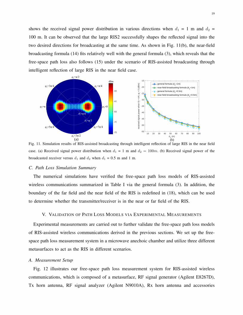
19
shows the received signal power distribution in various directions when d1 = 1 m and d2 =
100 m. It can be observed that the large RIS2 successfully shapes the reflected signal into the
two desired directions for broadcasting at the same time. As shown in Fig. 11(b), the near-field
broadcasting formula (14) fits relatively well with the general formula (3), which reveals that the
free-space path loss also follows (15) under the scenario of RIS-assisted broadcasting through
intelligent reflection of large RIS in the near field case.
φr=0
φr=π/2
φr=3π/2
φr=π
φr=π/4
φr=7π/4φr=5π/4
φr=3π/4
θr=π/6
θr=π/3
(a)
dBm
10 20 30 40 50 60 70 80 90 100
d2 (m)
-55
-50
-45
-40
-35
-30
-25
-20
-15
rr=
0 (
dBm
) general formula (d1=1m)
near-field broadcasting formula (d1=1m)
general formula (d1=0.5m)
near-field broadcasting formula (d1=0.5m)
(b)Fig. 11. Simulation results of RIS-assisted broadcasting through intelligent reflection of large RIS in the near field
case. (a) Received signal power distribution when d1 = 1 m and d2 = 100m. (b) Received signal power of the
broadcasted receiver versus d1 and d2 when d1 = 0.5 m and 1 m.
C. Path Loss Simulation Summary
The numerical simulations have verified the free-space path loss models of RIS-assisted
wireless communications summarized in Table I via the general formula (3). In addition, the
boundary of the far field and the near field of the RIS is redefined in (18), which can be used
to determine whether the transmitter/receiver is in the near or far field of the RIS.
V. VALIDATION OF PATH LOSS MODELS VIA EXPERIMENTAL MEASUREMENTS
Experimental measurements are carried out to further validate the free-space path loss models
of RIS-assisted wireless communications derived in the previous sections. We set up the free-
space path loss measurement system in a microwave anechoic chamber and utilize three different
metasurfaces to act as the RIS in different scenarios.
A. Measurement Setup
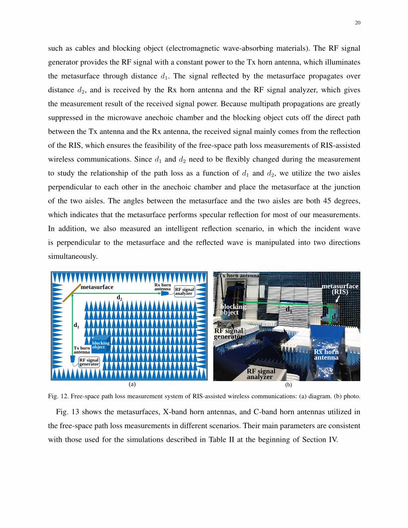
Fig. 12 illustrates our free-space path loss measurement system for RIS-assisted wireless
communications, which is composed of a metasurface, RF signal generator (Agilent E8267D),
Tx horn antenna, RF signal analyzer (Agilent N9010A), Rx horn antenna and accessories
20
such as cables and blocking object (electromagnetic wave-absorbing materials). The RF signal
generator provides the RF signal with a constant power to the Tx horn antenna, which illuminates
the metasurface through distance d1. The signal reflected by the metasurface propagates over
distance d2, and is received by the Rx horn antenna and the RF signal analyzer, which gives
the measurement result of the received signal power. Because multipath propagations are greatly
suppressed in the microwave anechoic chamber and the blocking object cuts off the direct path
between the Tx antenna and the Rx antenna, the received signal mainly comes from the reflection
of the RIS, which ensures the feasibility of the free-space path loss measurements of RIS-assisted
wireless communications. Since d1 and d2 need to be flexibly changed during the measurement
to study the relationship of the path loss as a function of d1 and d2, we utilize the two aisles
perpendicular to each other in the anechoic chamber and place the metasurface at the junction
of the two aisles. The angles between the metasurface and the two aisles are both 45 degrees,
which indicates that the metasurface performs specular reflection for most of our measurements.
In addition, we also measured an intelligent reflection scenario, in which the incident wave
is perpendicular to the metasurface and the reflected wave is manipulated into two directions
simultaneously.
metasurface
d1
d2
Tx hornantenna
Rx hornantenna
RF signalgenerator
RF signalanalyzer
blocking object
(a) (b)
metasurface(RIS)
Rx horn antenna
RF signalanalyzer
RF signalgenerator
Tx horn antenna
blocking object
d1d2
Fig. 12. Free-space path loss measurement system of RIS-assisted wireless communications: (a) diagram. (b) photo.
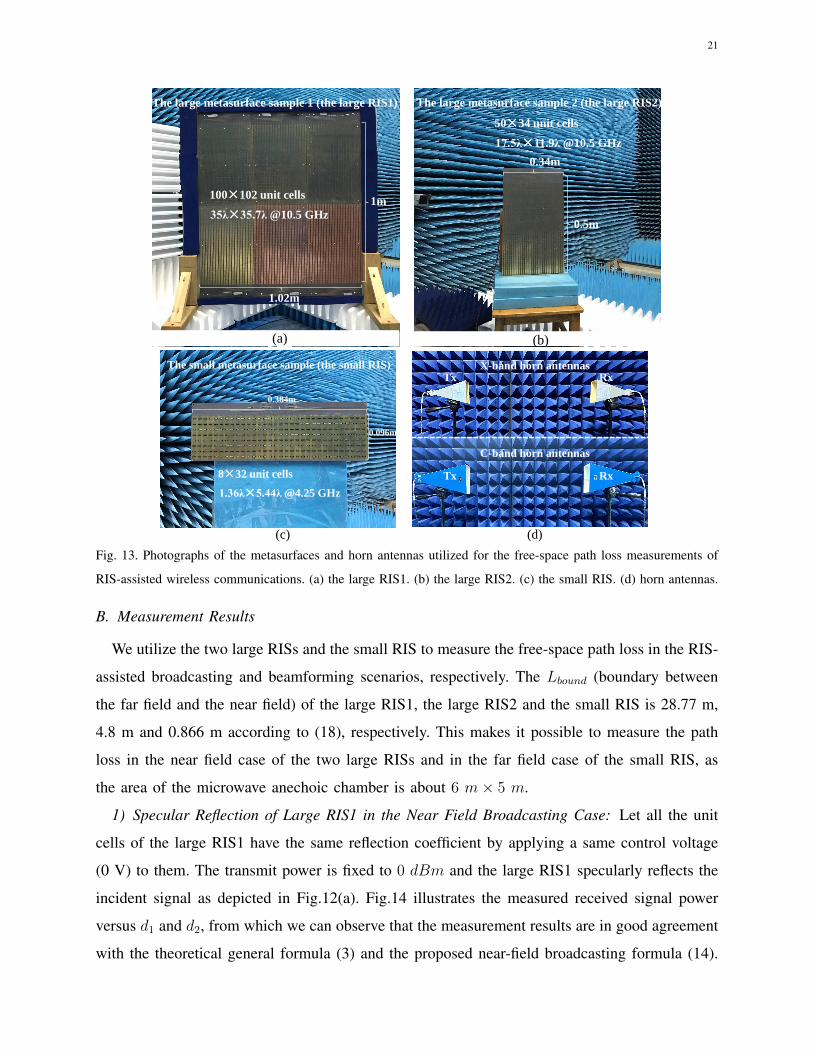
Fig. 13 shows the metasurfaces, X-band horn antennas, and C-band horn antennas utilized in
the free-space path loss measurements in different scenarios. Their main parameters are consistent
with those used for the simulations described in Table II at the beginning of Section IV.
21
1m
1.02m
100×102 unit cells
35λ×35.7λ @10.5 GHz
(a)
The large metasurface sample 1 (the large RIS1)
(b)
50×34 unit cells
17.5λ×11.9λ @10.5 GHz
0.5m
0.34m
The large metasurface sample 2 (the large RIS2)
(c)
8×32 unit cells
1.36λ×5.44λ @4.25 GHz
0.096m
0.384m
The small metasurface sample (the small RIS)
(d)
C-band horn antennas
X-band horn antennas
Tx Rx
Tx Rx
Fig. 13. Photographs of the metasurfaces and horn antennas utilized for the free-space path loss measurements of
RIS-assisted wireless communications. (a) the large RIS1. (b) the large RIS2. (c) the small RIS. (d) horn antennas.
B. Measurement Results
We utilize the two large RISs and the small RIS to measure the free-space path loss in the RIS-
assisted broadcasting and beamforming scenarios, respectively. The Lbound (boundary between
the far field and the near field) of the large RIS1, the large RIS2 and the small RIS is 28.77 m,
4.8 m and 0.866 m according to (18), respectively. This makes it possible to measure the path
loss in the near field case of the two large RISs and in the far field case of the small RIS, as
the area of the microwave anechoic chamber is about 6 m× 5 m.
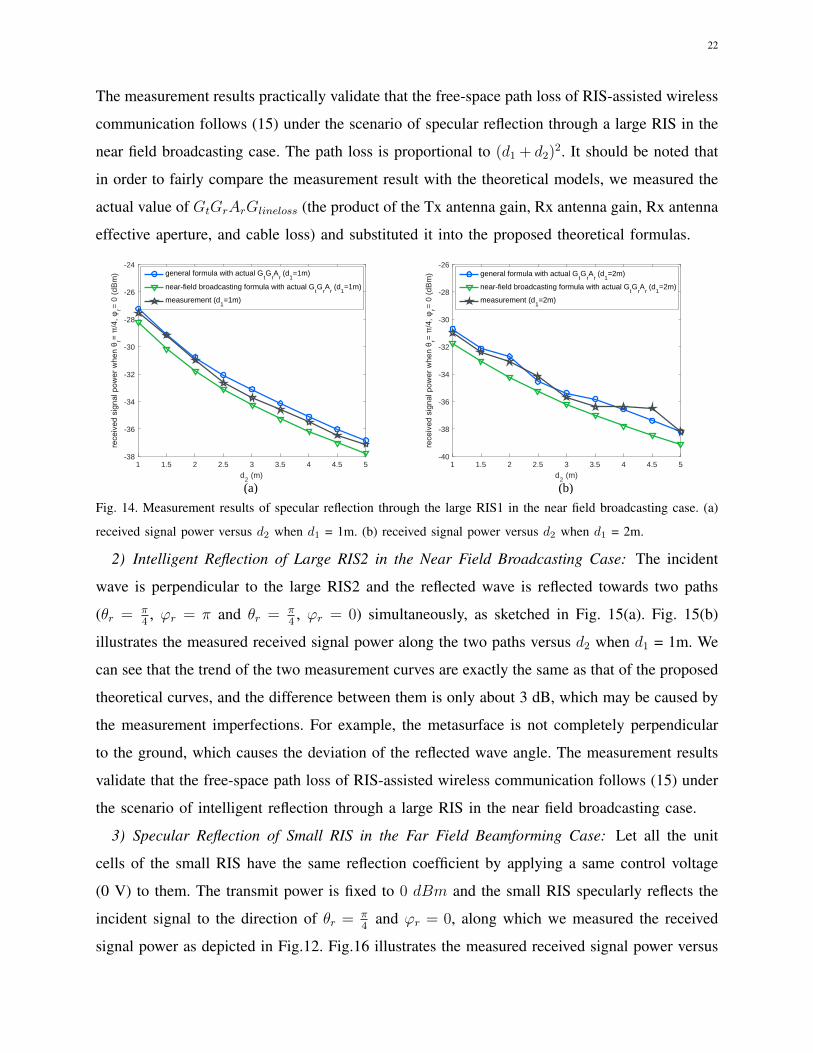
1) Specular Reflection of Large RIS1 in the Near Field Broadcasting Case: Let all the unit
cells of the large RIS1 have the same reflection coefficient by applying a same control voltage
(0 V) to them. The transmit power is fixed to 0 dBm and the large RIS1 specularly reflects the
incident signal as depicted in Fig.12(a). Fig.14 illustrates the measured received signal power
versus d1 and d2, from which we can observe that the measurement results are in good agreement
with the theoretical general formula (3) and the proposed near-field broadcasting formula (14).
22
The measurement results practically validate that the free-space path loss of RIS-assisted wireless
communication follows (15) under the scenario of specular reflection through a large RIS in the
near field broadcasting case. The path loss is proportional to (d1 + d2)2. It should be noted that
in order to fairly compare the measurement result with the theoretical models, we measured the
actual value of GtGrArGlineloss (the product of the Tx antenna gain, Rx antenna gain, Rx antenna
effective aperture, and cable loss) and substituted it into the proposed theoretical formulas.
1 1.5 2 2.5 3 3.5 4 4.5 5
d2 (m)
-38
-36
-34
-32
-30
-28
-26
-24
rr=
0 (
dBm
) general formula with actual GtG
rA
r (d
1=1m)
near-field broadcasting formula with actual GtG
rA
r (d
1=1m)
measurement (d1=1m)
(a)
1 1.5 2 2.5 3 3.5 4 4.5 5
d2 (m)
-40
-38
-36
-34
-32
-30
-28
-26
rr=
0 (
dBm
) general formula with actual GtG
rA
r (d
1=2m)
near-field broadcasting formula with actual GtG
rA
r (d
1=2m)
measurement (d1=2m)
(b)
Fig. 14. Measurement results of specular reflection through the large RIS1 in the near field broadcasting case. (a)
received signal power versus d2 when d1 = 1m. (b) received signal power versus d2 when d1 = 2m.
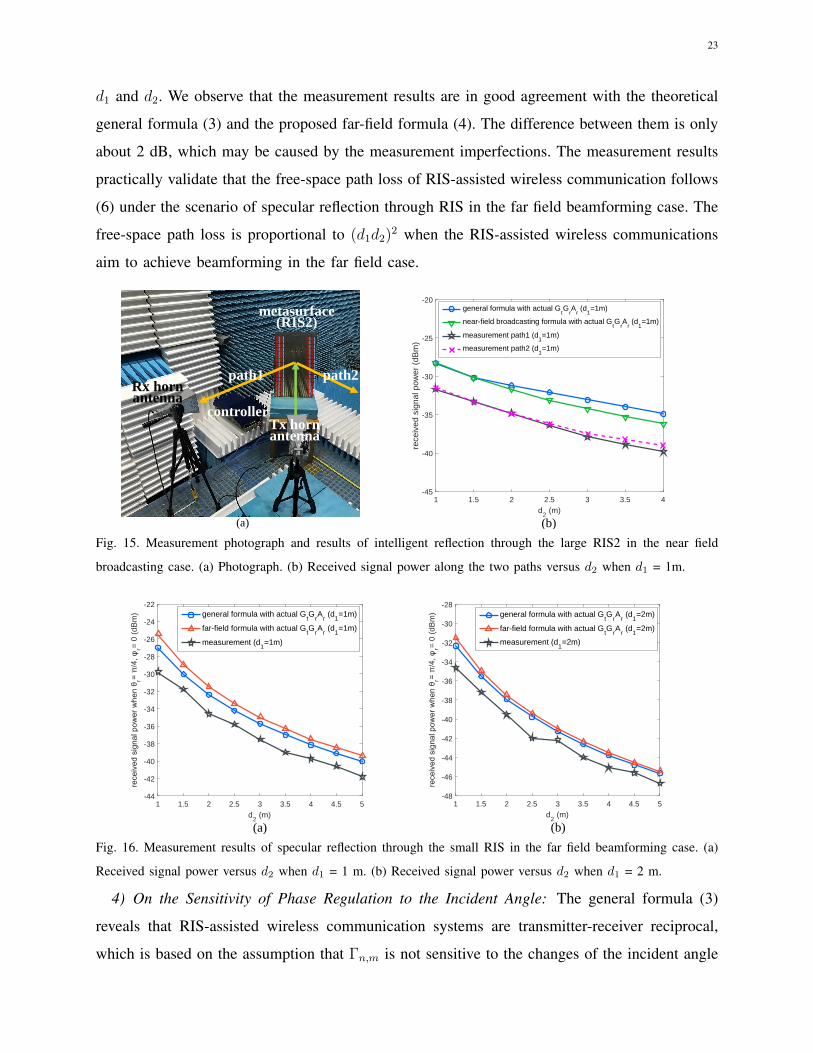
2) Intelligent Reflection of Large RIS2 in the Near Field Broadcasting Case: The incident
wave is perpendicular to the large RIS2 and the reflected wave is reflected towards two paths
(θr = π4, ϕr = π and θr = π
4, ϕr = 0) simultaneously, as sketched in Fig. 15(a). Fig. 15(b)
illustrates the measured received signal power along the two paths versus d2 when d1 = 1m. We
can see that the trend of the two measurement curves are exactly the same as that of the proposed
theoretical curves, and the difference between them is only about 3 dB, which may be caused by
the measurement imperfections. For example, the metasurface is not completely perpendicular
to the ground, which causes the deviation of the reflected wave angle. The measurement results
validate that the free-space path loss of RIS-assisted wireless communication follows (15) under
the scenario of intelligent reflection through a large RIS in the near field broadcasting case.
3) Specular Reflection of Small RIS in the Far Field Beamforming Case: Let all the unit
cells of the small RIS have the same reflection coefficient by applying a same control voltage
(0 V) to them. The transmit power is fixed to 0 dBm and the small RIS specularly reflects the
incident signal to the direction of θr = π4
and ϕr = 0, along which we measured the received
signal power as depicted in Fig.12. Fig.16 illustrates the measured received signal power versus
23
d1 and d2. We observe that the measurement results are in good agreement with the theoretical
general formula (3) and the proposed far-field formula (4). The difference between them is only
about 2 dB, which may be caused by the measurement imperfections. The measurement results
practically validate that the free-space path loss of RIS-assisted wireless communication follows
(6) under the scenario of specular reflection through RIS in the far field beamforming case. The
free-space path loss is proportional to (d1d2)2 when the RIS-assisted wireless communications
aim to achieve beamforming in the far field case.
0000000000000000
1111111111111111
0000000000000000
1111111111111111
0000000000000000
1111111111111111
0000000000000000
1111111111111111
. . . . . .
. . . . . .
(a)
Rx horn antenna
Tx horn antenna
metasurface(RIS2)
controller
path2path1
1 1.5 2 2.5 3 3.5 4
d2 (m)
-45
-40
-35
-30
-25
-20
rece
ived
sig
nal p
ower
(dB
m)
general formula with actual GtG
rA
r (d
1=1m)
near-field broadcasting formula with actual GtG
rA
r (d
1=1m)
measurement path1 (d1=1m)
measurement path2 (d1=1m)
(b)
Fig. 15. Measurement photograph and results of intelligent reflection through the large RIS2 in the near field
broadcasting case. (a) Photograph. (b) Received signal power along the two paths versus d2 when d1 = 1m.
1 1.5 2 2.5 3 3.5 4 4.5 5
d2 (m)
-44
-42
-40
-38
-36
-34
-32
-30
-28
-26
-24
-22
rr=
0 (
dBm
) general formula with actual GtG
rA
r (d
1=1m)
far-field formula with actual GtG
rA
r (d
1=1m)
measurement (d1=1m)
(a)
1 1.5 2 2.5 3 3.5 4 4.5 5
d2 (m)
-48
-46
-44
-42
-40
-38
-36
-34
-32
-30
-28
rr=
0 (
dBm
) general formula with actual GtG
rA
r (d
1=2m)
far-field formula with actual GtG
rA
r (d
1=2m)
measurement (d1=2m)
(b)
Fig. 16. Measurement results of specular reflection through the small RIS in the far field beamforming case. (a)
Received signal power versus d2 when d1 = 1 m. (b) Received signal power versus d2 when d1 = 2 m.
4) On the Sensitivity of Phase Regulation to the Incident Angle: The general formula (3)
reveals that RIS-assisted wireless communication systems are transmitter-receiver reciprocal,
which is based on the assumption that Γn,m is not sensitive to the changes of the incident angle
24
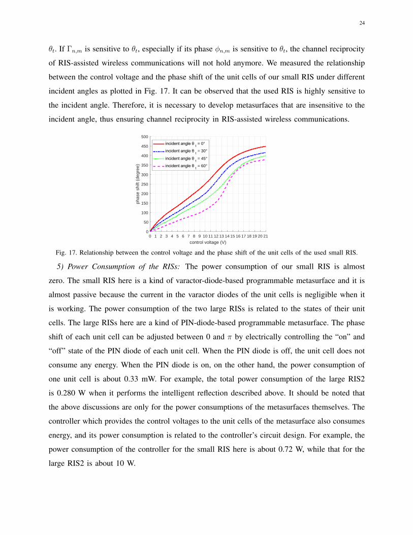
θt. If Γn,m is sensitive to θt, especially if its phase φn,m is sensitive to θt, the channel reciprocity
of RIS-assisted wireless communications will not hold anymore. We measured the relationship
between the control voltage and the phase shift of the unit cells of our small RIS under different
incident angles as plotted in Fig. 17. It can be observed that the used RIS is highly sensitive to
the incident angle. Therefore, it is necessary to develop metasurfaces that are insensitive to the
incident angle, thus ensuring channel reciprocity in RIS-assisted wireless communications.
0 1 2 3 4 5 6 7 8 9 10 11 12 13 14 15 16 17 18 19 20 21
control voltage (V)
0
50
100
150
200
250
300
350
400
450
500ph
ase
shift
(de
gree
)
t = 0°
t = 30°
t = 45°
t = 60°
Fig. 17. Relationship between the control voltage and the phase shift of the unit cells of the used small RIS.
5) Power Consumption of the RISs: The power consumption of our small RIS is almost
zero. The small RIS here is a kind of varactor-diode-based programmable metasurface and it is
almost passive because the current in the varactor diodes of the unit cells is negligible when it
is working. The power consumption of the two large RISs is related to the states of their unit
cells. The large RISs here are a kind of PIN-diode-based programmable metasurface. The phase
shift of each unit cell can be adjusted between 0 and π by electrically controlling the “on” and
“off” state of the PIN diode of each unit cell. When the PIN diode is off, the unit cell does not
consume any energy. When the PIN diode is on, on the other hand, the power consumption of
one unit cell is about 0.33 mW. For example, the total power consumption of the large RIS2
is 0.280 W when it performs the intelligent reflection described above. It should be noted that
the above discussions are only for the power consumptions of the metasurfaces themselves. The
controller which provides the control voltages to the unit cells of the metasurface also consumes
energy, and its power consumption is related to the controller’s circuit design. For example, the
power consumption of the controller for the small RIS here is about 0.72 W, while that for the
large RIS2 is about 10 W.
25
VI. CONCLUSION
In this paper, we have theoretically developed the free-space path loss models of RIS-assisted
wireless communications based on the electromagnetic and physics properties of the RISs. The
general formula which yields the free-space path loss of RIS-assisted wireless communications in
different scenarios was first proposed. Subsequently, three more insightful free-space path loss
models have been derived, namely the far-field formula, the near-field beamforming formula
and the near-field broadcasting formula, to characterize the free-space path loss of RIS-assisted
beamforming and broadcasting, respectively. In addition, the boundary of the far field and the
near field regimes of RIS-assisted wireless communications has been discussed according to the
numerical simulations. Moreover, free-space path loss measurements of RIS-assisted wireless
communications have been conducted in a microwave anechoic chamber by considering different
scenarios. The measurement results match quite well with the modeling results, which validates
the proposed path loss models. This work may help researchers in analyzing and simulating the
performance of various RIS-assisted wireless communication systems for application to future
wireless networks.
APPENDIX A
Proof of Theorem 1
The power of the incident signal into unit cell Un,m can be expressed as
P inn,m =
GtPt
4πrtn,m2F
tx(θtxn,m, ϕ
txn,m
)F(θtn,m, ϕ
tn,m
)dxdy, (19)
and the electric field of the incident signal into Un,m is given by
Einn,m =
√2Z0P in
n,m
dxdye
−j2πrtn,mλ , (20)
where Z0 is the characteristic impedance of the air, and rtn,m can be written as
rtn,m =
√(xt−
(m−1
2
)dx
)2
+
(yt−
(n−1
2
)dy
)2
+zt2. (21)
According to the law of energy conservation, for the unit cell Un,m, the power of the incident
signal times the square of the reflection coefficient is equal to the total power of the reflected
signal, thus we have
P inn,mΓ2
n,m = P reflectn,m , (22)
26
where P reflectn,m is the total reflected signal power of the unit cell Un,m, and the reflection coefficient
can be written as
Γn,m = An,mejφn,m , (23)
where An,m and φn,m represent the controllable amplitude and phase shift of Un,m, respectively.
The power of the reflected signal received by the receiver from Un,m can be expressed as
P rn,m =
GP reflectn,m
4πrrn,m2F(θrn,m, ϕ
rn,m
)F rx
(θrxn,m, ϕ
rxn,m
)Ar, (24)
where Ar represent the aperture of the receiving antenna, and rrn,m can be written as
rrn,m =
√(xr−
(m−1
2
)dx
)2
+
(yr−
(n−1
2
)dy
)2
+zr2. (25)
By combining (19), (22) and (24), the electric field of the reflected signal received by the
receiver from Un,m is obtained as
Ern,m =
√2Z0P r
n,m
Are
−j2πrtn,mλ e
−j2πrrn,mλ
=
√Z0PtGtGdxdyFcombine
8π2
Γn,mrtn,mr
rn,m
e−j2π(rtn,m+rrn,m)
λ .
(26)
The total electric field of the received signal is the superposition of the electric fields reflected
by all unit cells toward the receiver, which can be written as
Er =
M2∑
m=1−M2
N2∑
n=1−N2
Ern,m. (27)
The received signal power of the receiver is
Pr =|Er|2
2Z0
Ar, (28)
where the aperture of the receiving antenna can be written as
Ar =Grλ
2
4π. (29)
We obtain Theorem 1 by substituting (26), (27), and (29) into (28).
27
APPENDIX B
Proof of Proposition 1
The position of the transmitter in Fig. 2 is
(xt, yt, zt) = (d1 sin θt cosϕt, d1 sin θt sinϕt, d1 cos θt). (30)
By combining (21) and (30), when the transmitter is in the far field of the RIS, rtn,m can be
further expressed as
rtn,m =
√(d1 sin θt cosϕt−(m−1
2)dx
)2
+
(d1 sin θt sinϕt−(n−1
2)dy
)2
+(d1 cos θt)2
≈ d1− sin θt cosϕt(m−1
2)dx− sin θt sinϕt(n−
1
2)dy,
(31)
Similarly, the position of the receiver in Fig. 2 is
(xr, yr, zr) = (d2 sin θr cosϕr, d2 sin θr sinϕr, d2 cos θr). (32)
By combining (25) and (32), when the receiver is in the far field of the RIS, rrn,m can be
further expressed as
rrn,m =
√(d2 sin θr cosϕr−(m−1
2)dx
)2
+
(d2 sin θr sinϕr−(n−1
2)dy
)2
+(d2 cos θr)2
≈ d2− sin θr cosϕr(m−1
2)dx− sin θr sinϕr(n−
1
2)dy,
(33)
In the far field case, (θtn,m, ϕtn,m) and (θrn,m, ϕ
rn,m) can be approximated as (θt, ϕt) and (θr, ϕr),
respectively. In addition, as assuming that the direction of peak radiation of both the transmitting
antenna and receiving antenna point to the center of the RIS, we have F tx(θtxn,m, ϕtxn,m) ≈ 1 and
F rx(θrxn,m, ϕrxn,m) ≈ 1 in the far field case.
By substituting (31) and (33) into the general formula (3), the received signal power can be
further written as
Pr ≈ PtGtGrGdxdyλ
2
64π3
∣∣∣∣∣∣M2∑
m=1−M2
N2∑
n=1−N2
√F (θt, ϕt)F (θr, ϕr) Γn,m
e−j2παλ
d1d2
∣∣∣∣∣∣2
= PtGtGrGdxdyλ
2F (θt, ϕt)F (θr, ϕr)
64π3d12d2
2
∣∣∣∣∣∣M2∑
m=1−M2
N2∑
n=1−N2
Γn,m ej2π(d1+d2−α)
λ
∣∣∣∣∣∣2
,
(34)
where α=d1− sin θt cosϕt(m−12)dx− sin θt sinϕt(n−1
2)dy+d2− sin θr cosϕr(m−1
2)dx−
sin θr sinϕr(n−12)dy.
28
As all the unit cells of RIS share the same reflection coefficient Aejφ, (34) can be written as
Pr = PtGtGrGdxdyλ
2F (θt, ϕt)F (θr, ϕr)A2
64π3d12d2
2 |β|2, (35)
where
β =
M2∑
m=1−M2
N2∑
n=1−N2
ej2π((sin θt cosϕt+sin θr cosϕr)(m− 1
2 )dx+(sin θt sinϕt+sin θr sinϕr)(n− 12 )dy)
λ . (36)
Define u = 2πλ
(sin θt cosϕt + sin θr cosϕr)dx and v = 2πλ
(sin θt sinϕt + sin θr sinϕr)dy, then
(36) can be rewritten as
β =
M2∑
m=1−M2
N2∑
n=1−N2
ej(m−12
)uej(n−12
)v =
M2∑
m=1−M2
ej(m−12
)u
N2∑
n=1−N2
ej(n−12
)v (37)
By applying the formula of the sum of the geometric progression, (37) can be rewritten as
β =e−j
Mu2 − ejMu
2
e−ju2 − ej u2
e−jNv2 − ejNv2
e−jv2 − ej v2
=sin(Mu
2
)sin(u2
) sin(Nv2
)sin(v2
) = MNsinc
(Mu
2
)sinc(u
2)
sinc(Nv2
)sinc
(v2
)= MN
sinc(Mπλ
(sin θt cosϕt+ sin θr cosϕr)dx)
sinc(πλ(sin θt cosϕt+ sin θr cosϕr)dx)
sinc(Nπλ
(sin θt sinϕt+ sin θr sinϕr)dy)
sinc(πλ(sin θt sinϕt+ sin θr sinϕr)dy
) .(38)
By plugging (38) into (35), the received signal power in the far field case can be obtained as
stated in (4). When sin θt cosϕt + sin θr cosϕr = 0 and sin θt sinϕt + sin θr sinϕr = 0, that is,
θr = θt and ϕr = ϕt + π, (4) is maximized as stated in (5).
Proof of Proposition 2
For the intelligent reflection in the far field case, by substituting Γn,m = Aejφn,m into (34),
we have
Pr = PtGtGrGdxdyλ
2F (θt, ϕt)F (θr, ϕr)A2
64π3d12d2
2
∣∣∣β∣∣∣2, (39)
where
β =
M2∑
m=1−M2
N2∑
n=1−N2
ej2π((sin θt cosϕt+sin θr cosϕr)(m− 1
2 )dx+(sin θt sinϕt+sin θr sinϕr)(n− 12 )dy+
λφn,m2π )
λ . (40)
Define u = 2πλ
(sin θt cosϕt+sin θr cosϕr+δ1)dx and v = 2πλ
(sin θt sinϕt+sin θr sinϕr+δ2)dy,
where δ1
(m− 1
2
)dx + δ2
(n− 1
2
)dy = λφn,m
2π, (40) can be rewritten as
β =
M2∑
m=1−M2
N2∑
n=1−N2
ej(m−12
)uej(n−12
)v =
M2∑
m=1−M2
ej(m−12
)u
N2∑
n=1−N2
ej(n−12
)v (41)
29
Similarly, by applying the formula of the sum of the geometric progression, the received signal
power can be obtained as (7), which is maximized when sin θt cosϕt + sin θr cosϕr + δ1 = 0
and sin θt sinϕt + sin θr sinϕr + δ2 = 0.
Proof of Proposition 3
By substituting Γn,m = Aejφn,m into the general formula (3), (10) can be simply obtained. For
the desired receiver at (xr, yr, zr), (10) is maximized as (11) when 2π(rtn,m+rrn,m)−λφn,m = 0,
which can be further expressed as (12).
REFERENCES
[1] Huawei, “Asia-Pacific leads 5G innovation, Huawei enables sustainable development of a digital economy,” Sep. 2019.
[Online]. Available: https://www.huawei.com/en/press-events/news/2019/9/huawei-5th-asia-pacific-innovation-day.
[2] T. S. Rappaport et al., “Wireless communications and applications above 100 GHz: Opportunities and challenges for 6G
and beyond,” IEEE Access, vol. 7, pp. 78729-78757, Jun. 2019.
[3] Y. Zeng and R. Zhang, “Millimeter wave MIMO with lens antenna array: A new path division multiplexing paradigm,”
IEEE Trans. Commun., vol. 64, no. 4, pp. 1557-1571, Apr. 2016.
[4] F. Tariq, M. R. A. Khandaker, K.-K. Wong, M. Imran, M. Bennis, and M. Debbah, “A speculative study on 6G,” [Online].
Available: https://arxiv.org/abs/1902.06700
[5] I. F. Akyildiz, C. Han, and S. Nie, “Combating the distance problem in the millimeter wave and terahertz frequency bands,”
IEEE Commun. Mag., vol. 56, no. 6, pp. 102-108, Jun. 2018.
[6] C. Han, J. M. Jornet, and I. F. Akyildiz, “Ultra-massive MIMO channel modeling for graphene-Enabled terahertz-band
communications,” Proc. IEEE VTC Spring, Jun. 2018, pp. 15.
[7] S. Hu, F. Rusek, and O. Edfors, “Beyond massive MIMO: The potential of data transmission with large intelligent surfaces,”
IEEE Trans. Signal Process., vol. 66, no. 10, pp. 274658, May. 2018.
[8] Z. Zhang et al., “6G wireless networks: Vision, requirements, architecture, and key technologies,” Vehicular Technology
Magazine, vol. 14, no. 3, pp. 28-41, Sep. 2019.
[9] T. J. Cui et al., “Information metamaterials and metasurfaces,” J. Mater. Chem. C., no. 15, pp. 3644-3668, May 2017.
[10] J. Zhao et al., “Programmable time-domain digital-coding metasurface for non-linear harmonic manipulation and new
wireless communication systems,” National Sci. Rev., vol. 6, no. 2, pp. 231-238, Mar. 2019.
[11] L. Zhang et al., “Space-time-coding digital metasurfaces,” Nat. Commun., vol. 9, Oct. 2018.
[12] W. Tang, X. Li, J. Y. Dai, S. Jin, Y. Zeng, Q. Cheng, and T. J. Cui, “Wireless communications with programmable
metasurface: Transceiver design and experimental results,” China Commun., vol. 16, no. 5, pp. 46-61, May 2019.
[13] W. Tang, J. Y. Dai, M. Chen, X. Li, Q. Cheng, S. Jin, K.-K. Wong, and T. J. Cui, “Programmable metasurface-based RF
chain-free 8PSK wireless transmitter,” Electron. Lett., vol. 55, no. 7, pp. 417-420, Apr. 2019.
[14] W. Tang et al., “Wireless communications with programmable metasurface: New paradigms, opportunities, and challenges
on transceiver design,” [Online]. Available: https://arxiv.org/abs/1907.01956.
[15] J. Y. Dai et al., “Wireless communications through a simplified architecture based on time-domain digital coding
metasurface,” Adv. Mater. Technol., vol. 4, no. 7, pp. 18, Jul. 2019.
[16] M. Di Renzo et al., “Smart radio environments empowered by reconfigurable AI meta-surfaces: An idea whose time has
come,” EURASIP J. Wireless Commun. Netw., vol. 2019, no. 1, p. 129, May 2019.
30
[17] Q. Wu and R. Zhang, “Towards smart and reconfgurable environment: Intelligent refecting surface aided wireless network,”
IEEE Commun. Mag., to appear. [Online]. Available: https://arxiv.org/abs/1905.00152.
[18] C. Liaskos, S. Nie, A. Tsioliaridou, A. Pitsillides, S. Ioannidis, and I. F. Akyildiz, “A new wireless communication paradigm
through software-controlled metasurfaces,” IEEE Commun. Mag., vol. 56, no. 9, pp. 162-169, Sep. 2018, .
[19] E. Basar, M. Di Renzo, J. De Rosny, M. Debbah, M. Alouini, and R. Zhang, “Wireless communications through
reconfigurable intelligent surfaces,” IEEE Access, vol. 7, pp. 116753-116773, Aug. 2019.
[20] Q. Wu and R. Zhang, “Intelligent reflecting surface enhanced wireless network via joint active and passive beamforming,”
IEEE Trans. Wireless Commun., early access, Aug. 2019, pp. 1–16.
[21] M. Cui, G. Zhang and R. Zhang, “Secure wireless communication via intelligent reflecting surface,” IEEE Wireless Commun.
Lett., vol. 8, no. 5, pp. 1410-1414, Oct. 2019.
[22] J. Chen, Y.-C. Liang, Y. Pei and H. Guo, “Intelligent reflecting surface: A programmable wireless environment for physical
layer security,” IEEE Access, vol. 7, pp. 82599-82612, Jun. 2019.
[23] M. Jung, W. Saas, M. Debbah, and C. S. Hong “On the optimality of reconfigurable intelligent surfaces (RISs): Passive
beamforming, modulation, and resource allocation,” [Online]. Available: https://arxiv.org/abs/1910.00968.
[24] S. Li, B. Duo, X. Yuan, Y.-C. Liang, and M. D. Renzo, “Reconfigurable intelligent surface assisted UAV communication:
Joint trajectory design and passive beamforming” [Online]. Available: https://arxiv.org/abs/1908.04082.
[25] H. Guo, Y.-C. Liang, J. Chen, and E. G. Larsson, “Weighted sum-rate optimization for intelligent reflecting surface enhanced
wireless networks,” [Online]. Available: https://arxiv.org/abs/1905.07920.
[26] C. Huang, A. Zappone, G. C. Alexandropoulos, M. Debbah, and C. Yuen, “Reconfigurable intelligent surfaces for energy
efficiency in wireless communication,” IEEE Trans. Wireless Commun., vol. 18, no. 8, pp. 4157-4170, Aug. 2019.
[27] C. Huang, G. C. Alexandropoulos, A. Zappone, M. Debbah, and C. Yuen, “Energy efficient multi-user MISO communication
using low resolution large intelligent surfaces,” in Proc. IEEE Global Commun. Conf., Abu Dhabi, UAE, Dec. 2018.
[28] C. Pan et al., “Intelligent reflecting surface aided MIMO broadcasting for simultaneous wireless information and power
transfer,” [Online]. Available: https://arxiv.org/abs/1908.04863v3.
[29] Y. Han, W. Tang, S. Jin, C.-K. Wen, and X. Ma, “Large intelligent surface-assisted wireless communication exploiting
statistical CSI,” IEEE Trans. Veh. Technol., vol. 68, no. 8, pp. 8238-8242, Aug. 2019.
[30] E. Basar, “Transmission through large intelligent surfaces: A new frontier in wireless communications,” in Proc. Eur. Conf.
Netw. Commun. (EuCNC), Valencia, Spain, Jun. 2019, pp. 112-117.
[31] M. Jung, W. Saad, Y. Jang, G. Kong and S. Choi, “Reliability analysis of large intelligent surfaces (LISs): Rate distribution
and outage probability,” IEEE Wireless Commun. Lett., early access, Aug. 2019, pp. 14.
[32] K. Ntontin et al., “Reconfigurable intelligent surfaces vs. relaying: Differences, similarities, and performance comparison,”
[Online]. Available: https://arxiv.org/abs/1908.08747.
[33] Q. Wu and R. Zhang, “Beamforming optimization for intelligent reflecting surface with discrete phase shifts,” in Proc.
IEEE Int. Conf. Acoust., Speech Signal Process. (ICASSP), Brighton, U.K., May 2019, pp. 7830-7833.
[34] S. Abeywickrama, R. Zhang, and C. Yuen, “Intelligent reflecting surface: Practical phase shift model and beamforming
optimization,” [Online]. Available: https://arxiv.org/abs/1907.06002.
[35] Y. Huang and K. Boyle, Antennas: from theory to practice. Chichester: Wiley, 2008.
[36] W. L. Stutzman and G. A. Thiele, Antenna theory and design. New York: Wiley, 1998.
[37] A. Goldsmith, Wireless Communications. Cambridge, U.K.: Cambridge University Press, 2005.