Embed Size (px)
Citation preview

Wireless Communications
Lyubov Knyazeva-Renselaerwww.IEEE.org
www.wie.liEmail: [email protected]
Swiss AlpsToday, we can all be in touch with the digital resources we need, no matter where we may find ourselves.
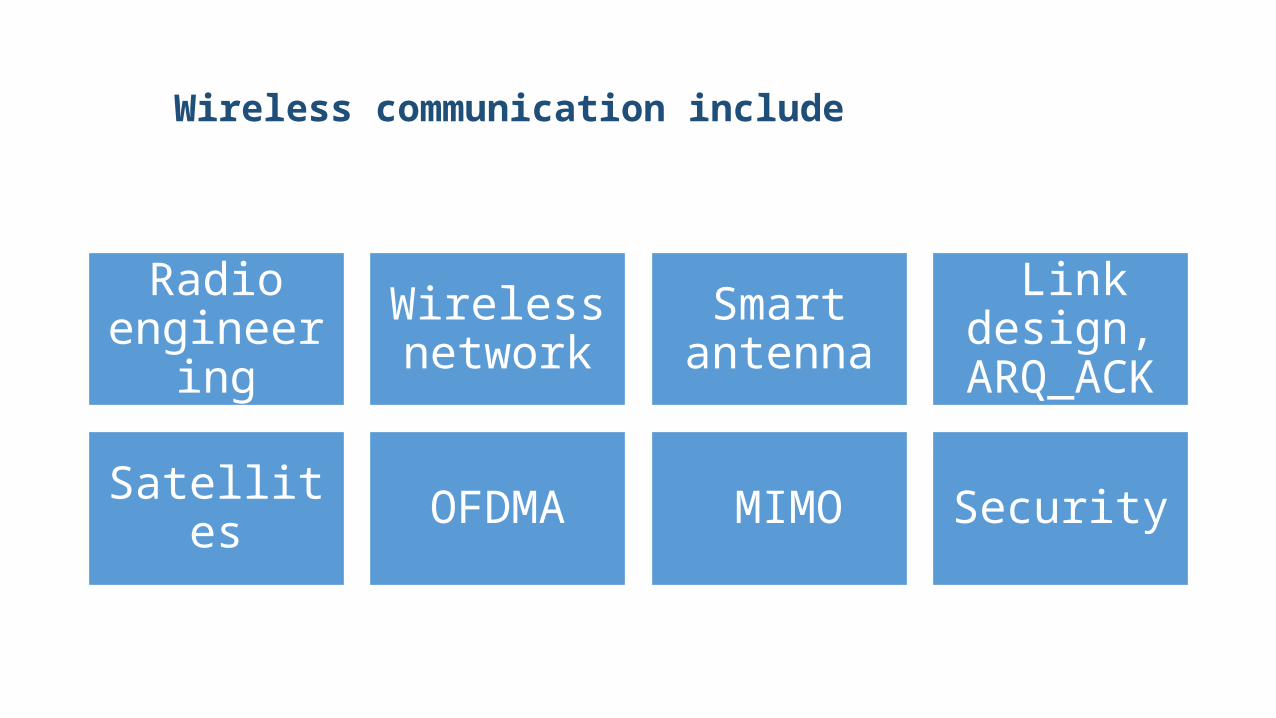
Wireless communication include
Radio engineering
Wireless network
Smart antenna
Link design, ARQ_ACK
Satellites OFDMA MIMO Security
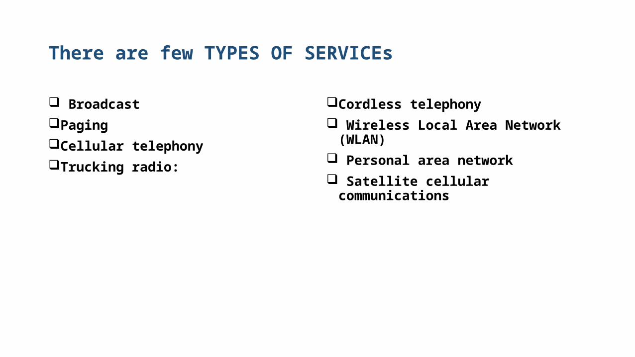
There are few TYPES OF SERVICEs
BroadcastPaging Cellular telephonyTrucking radio:
Cordless telephony Wireless Local Area Network (WLAN) Personal area network Satellite cellular communications
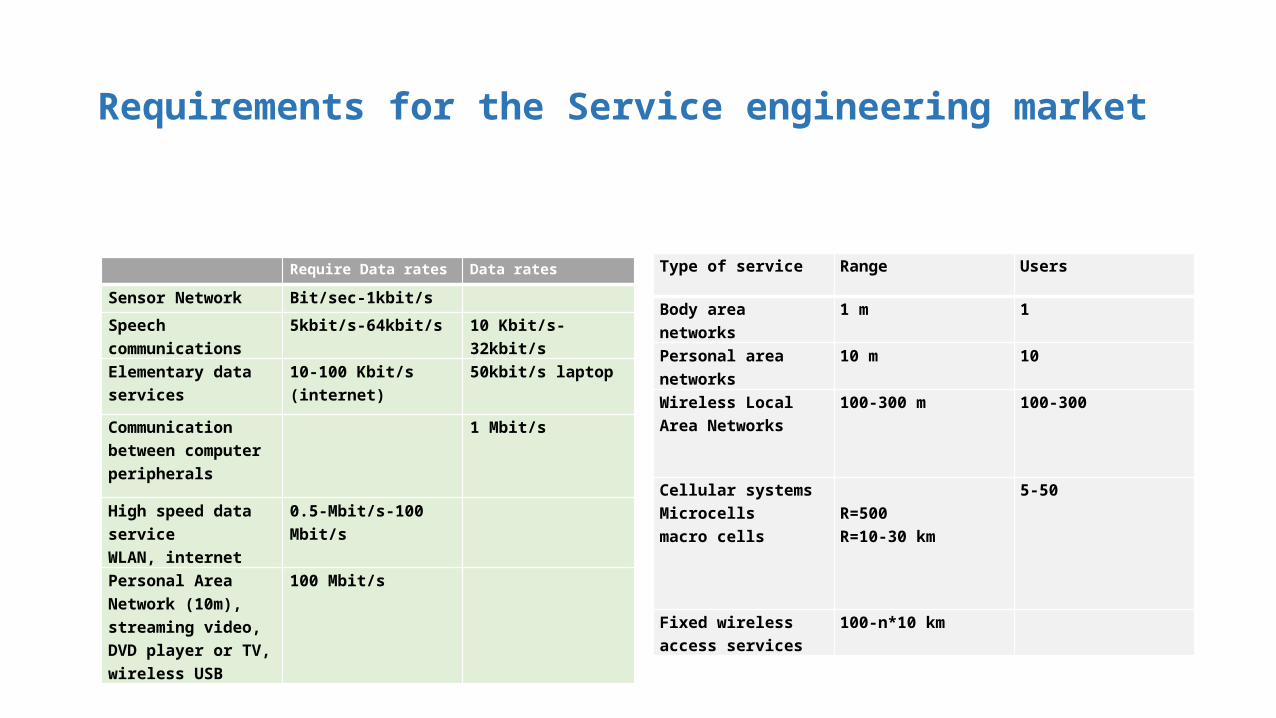
Requirements for the Service engineering market
Require Data rates Data rates
Sensor Network Bit/sec-1kbit/s
Speech communications 5kbit/s-64kbit/s 10 Kbit/s-32kbit/s
Elementary data services 10-100 Kbit/s (internet) 50kbit/s laptop
Communication between computer peripherals
1 Mbit/s
High speed data serviceWLAN, internet
0.5-Mbit/s-100 Mbit/s
Personal Area Network (10m), streaming video, DVD player or TV, wireless USB
100 Mbit/s
Type of service Range Users
Body area networks 1 m 1
Personal area networks 10 m 10
Wireless Local Area Networks
100-300 m 100-300
Cellular systemsMicrocellsmacro cells
R=500R=10-30 km
5-50
Fixed wireless access services
100-n*10 km

Principles and Attributes of Radio Engineering
POWER MODULATION LINK DESIGN
ANTENNA TECHNOLOGY PROPAGATION
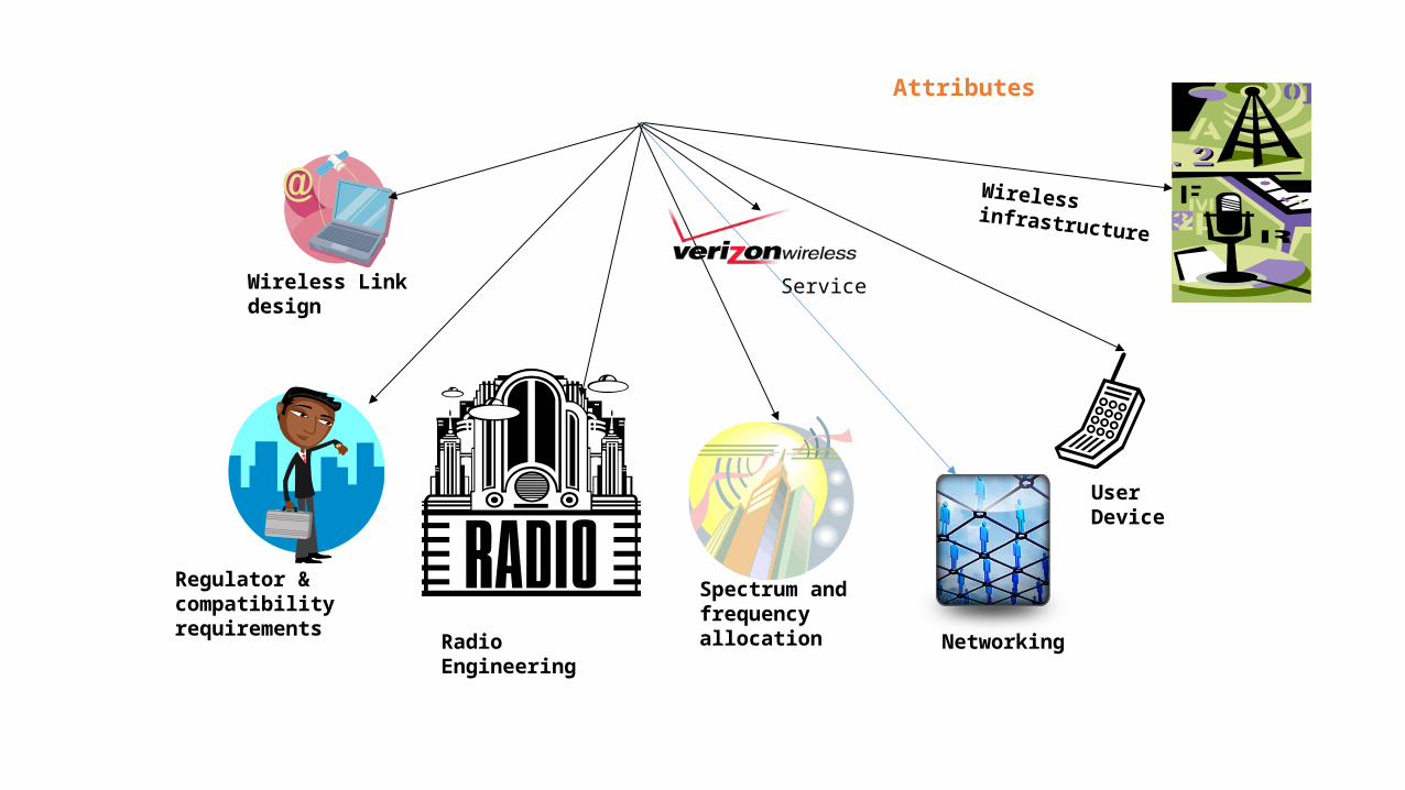
Attributes
Radio Engineering
Wireless Link design
Spectrum and frequencyallocation
User Device
Service
Regulator &compatibilityrequirements
Wireless infrastructure
Networking
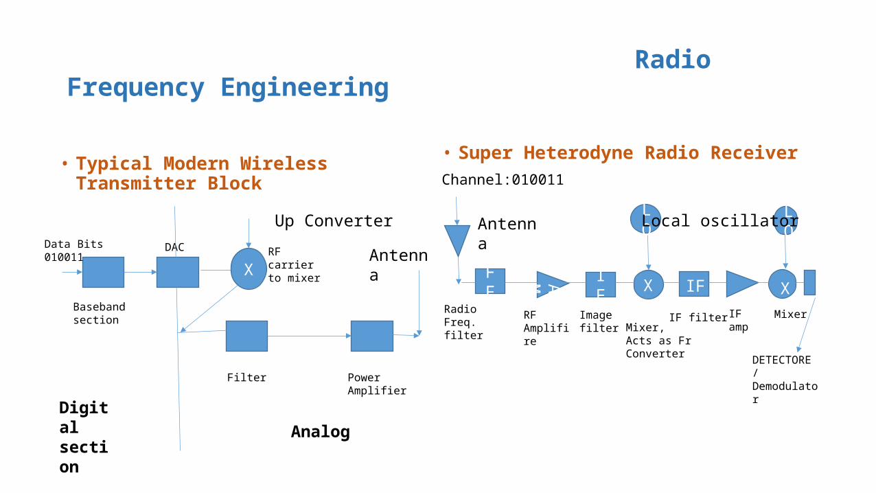
Radio Frequency Engineering
• Typical Modern Wireless Transmitter Block • Super Heterodyne Radio ReceiverChannel:010011
RFF AM IF
RadioFreq.filter
RFAmplifire
Imagefilter
LO
LO
Mixer, Acts as Fr Converter
IF amp MixerIF filter
DETECTORE/DemodulatorFilter
Baseband section
XRF carrier to mixer
Power Amplifier
AnalogDigital section
AntennaData Bits010011
DAC
Up Converter Local oscillator
X IF X
Antenna
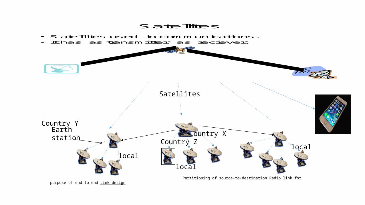
Satellite Path Satellites
• Satellites used in communications.
• It has as transmitter as reciever.
Country Y
Country X Country Z
Satellites
Uplink
Freq. = 6 GHZ DownlinkFreq. = 4 GHZ
Partitioning of source-to-destination Radio link for purpose of end-to-end Link design
Earth station
local local
local
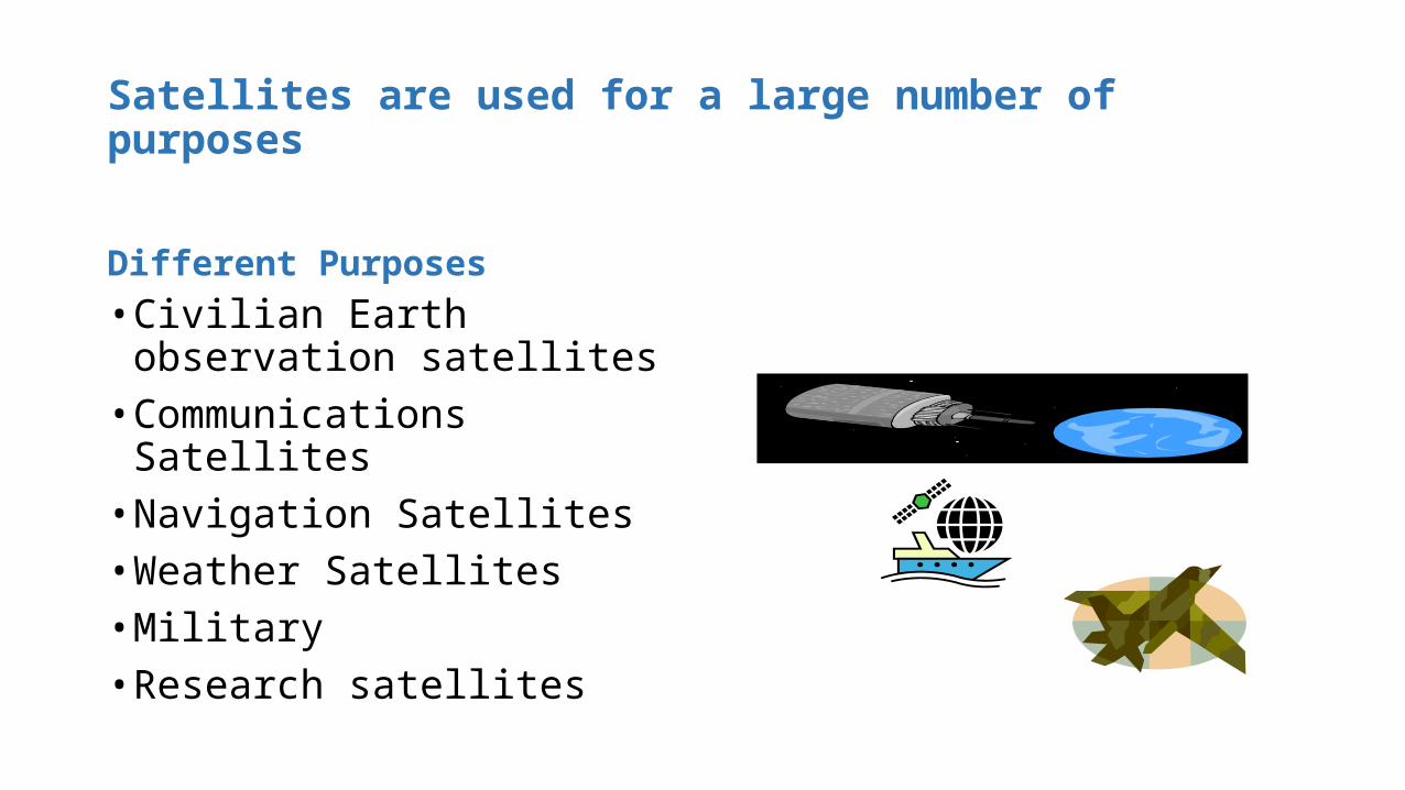
Satellites are used for a large number of purposes
Different Purposes• Civilian Earth observation
satellites• Communications Satellites• Navigation Satellites• Weather Satellites• Military• Research satellites
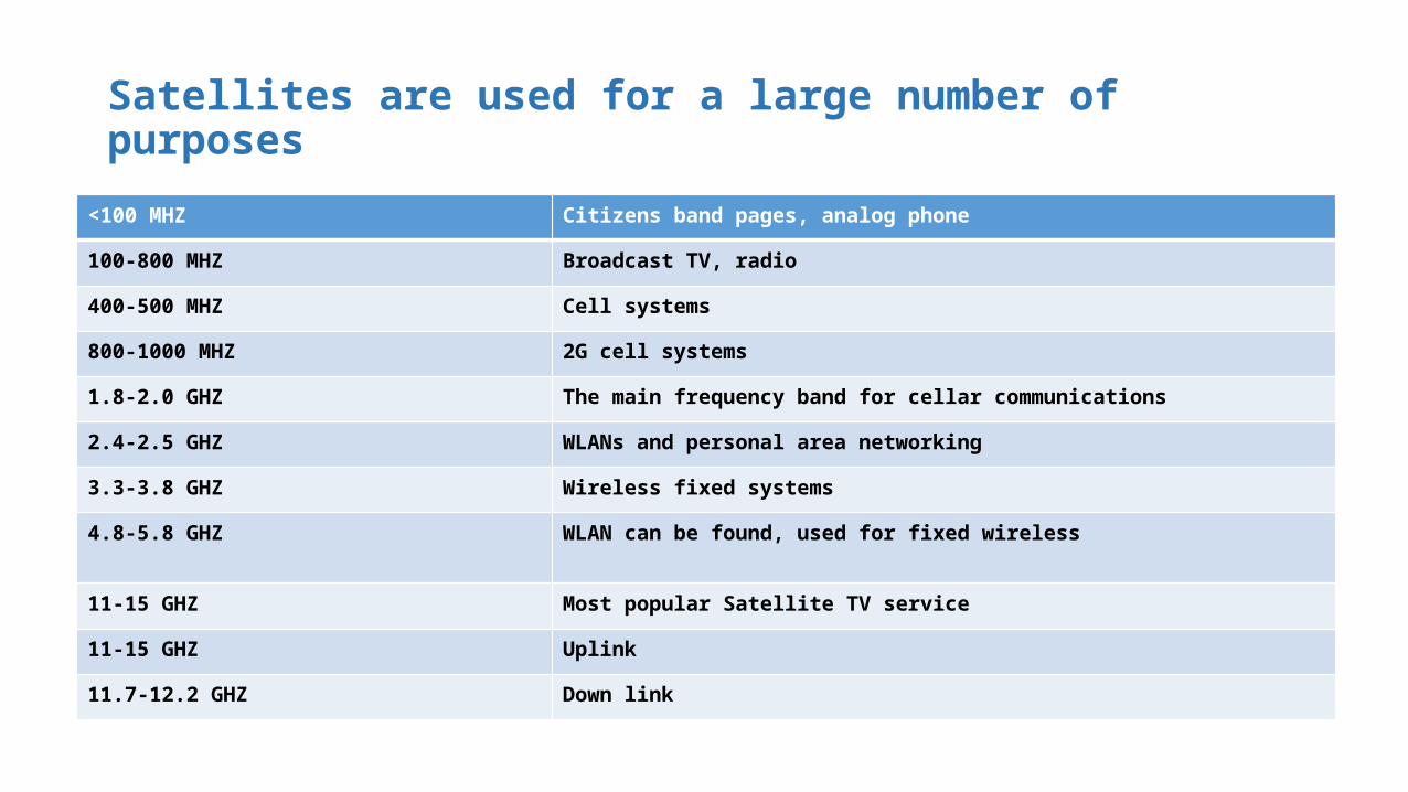
Satellites are used for a large number of purposes
<100 MHZ Citizens band pages, analog phone
100-800 MHZ Broadcast TV, radio
400-500 MHZ Cell systems
800-1000 MHZ 2G cell systems
1.8-2.0 GHZ The main frequency band for cellar communications
2.4-2.5 GHZ WLANs and personal area networking
3.3-3.8 GHZ Wireless fixed systems
4.8-5.8 GHZ WLAN can be found, used for fixed wireless
11-15 GHZ Most popular Satellite TV service
11-15 GHZ Uplink
11.7-12.2 GHZ Down link

Frequency band designation
Banddesignation
VHF UHF L S C X KU K KA V W mm mm
Frequency range,GHZ
0.1-0.3
0.3-1.0
1.0-2.0
2.0-4.0
4.0-8.0
8.0-12.0
12.0-18.0
18.0-27.0
27.0-40.0
40.0-75
75-110
110-300
300-3000

Satellites Communications
Geostationary orbit well established for communications
• A circle at an altitude of =35786 km • A single Geostationary provide communications• to areas > 1/3 of the Earth.• The Geostationary satellites placed 120 degree
apart• The Satellite velocity in this orbit V=3075
(m/sec); Disadvantages:• Propagation delays = 250 ms from transmitter to
receiver • Sun is a strong source of noise.
• LEO (Low Earth Orbit)• Phone service to remote areas• Iridium (#66)• Global Star systems• Cascade System
• MEO (Medium Earth Orbit)• Large coverage Area
• GEO (Geostationary orbit)• Provide microwave radio relay technology for communication
cables;• Communications for ships, vehicles,• TV broadcasting• Radio broadcasting • Weather forecasting
• HEO (High Earth Orbit) provide continues service to a very large foot print, monitor compliance with the nuclear test ban agreements, satellite service in the Polar Regions
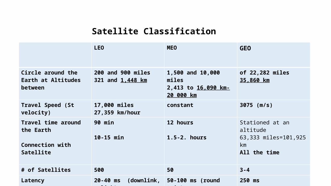
Satellite Classification
LEO MEO GEO
Circle around the Earth at Altitudes between
200 and 900 miles321 and 1,448 km
1,500 and 10,000 miles2,413 to 16,090 km-20 000 km
of 22,282 miles35,860 km
Travel Speed (St velocity) 17,000 miles27,359 km/hour
constant 3075 (m/s)
Travel time around the Earth
Connection with Satellite
90 min
10-15 min
12 hours
1.5-2. hours
Stationed at an altitude63,333 miles=101,925 kmAll the time
# of Satellites 500 50 3-4
Latency 20-40 ms (downlink, uplink) 50-100 ms (round trip) 250 ms
DW Data RatesUP Data Rates
400 Kbps2 way: 500 Kbps
Orbits and Launching Methods
• Satellites (spacecraft) which orbit the Earth follow the same lows that govern the motion of the planets around the sun.
Johannes Kepler (1571-1630):
• Derives 3 lows, describing planetary motion.Sir Isaac Newton (1642-1727) develop the theory of gravitation.
Kepler’s laws apply quite generally to any two bodies in space which interact through gravitation.
• The more massive of the two bodies is referred to as primary,
• the other, the secondary, or satellite.
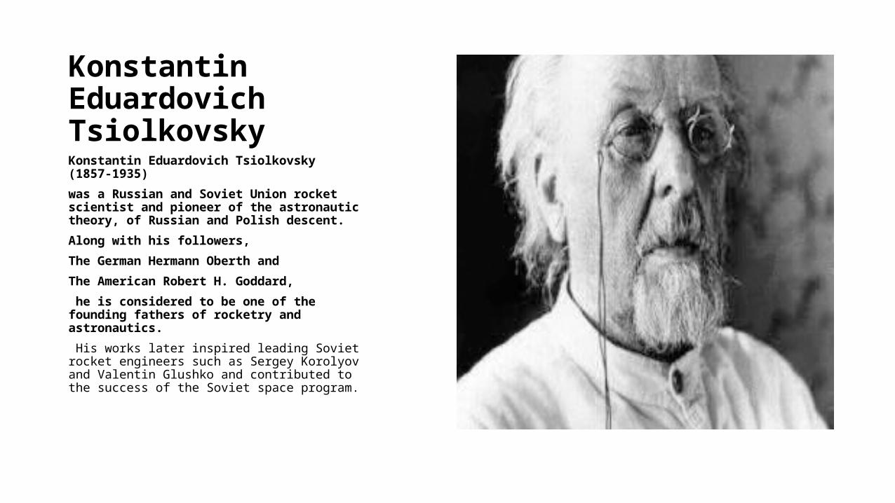
Konstantin Eduardovich TsiolkovskyKonstantin Eduardovich Tsiolkovsky (1857-1935)
was a Russian and Soviet Union rocket scientist and pioneer of the astronautic theory, of Russian and Polish descent.
Along with his followers,
The German Hermann Oberth and
The American Robert H. Goddard,
he is considered to be one of the founding fathers of rocketry and astronautics.
His works later inspired leading Soviet rocket engineers such as Sergey Korolyov and Valentin Glushko and contributed to the success of the Soviet space program.

Frequency Planning
To facilitate the frequency Planning, the world is divided into 3 Regions:
• Region 1: Europe, Africa, Russia and Mongolia• Region 2: North and South America, and Greenland • Region 3: Asia, Australia, South- West Pacific
At These Regions frequency Bands are allocated to various Satellite Services.
Although a given service may be allocated different frequency bands in different regions.
Some of the services provided by Satellites are:
• Fixed Satellite service (FSS)
• Broadcasting Satellite Service (BSS)
• Mobile satellite Service (MSS)
• Navigation Satellite Service (NSS)
• Meteorological Satellite Service (MetSS)

Example of Utilization different operational frequencies by Universal Mobile Telecommunications system (UMTS)
1650MHZTDD
1700MHZ
1750MHZ
1800MHZ
1850MHZ
1900MHZ
1950MHZ
2000MHZ
2050MHZ
2100 2150 2200
B1 1880TDD
1920TDD
1920M
1980M wired
TDD20102025
2110BS
2170BSWired
B2 1710MSWired
1785MS
1805BSWired
1880BS
B3 1850MSWired
1910TDD
1930BSWired
1990BS
B4 1710MSWired
1785MS
1805BSWired
1880TDD
1920TDD
1980MS
2010-2025TDD
2110BS
2160BS Wired
B5 1710 1930 1990BS
2110BS
2160BS
B6 1710 1770 1850 1910 1930 1990 2110BS
2170BS
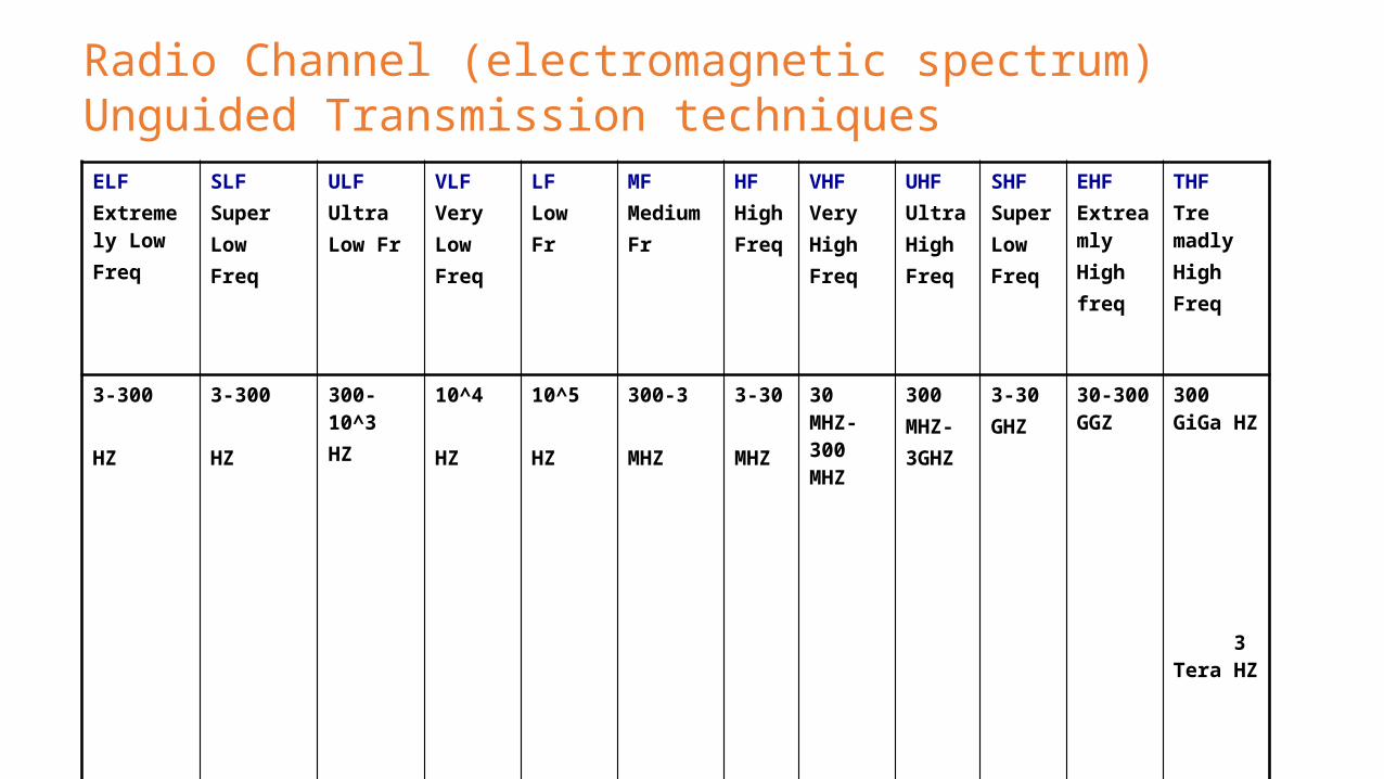
Radio Channel (electromagnetic spectrum)Unguided Transmission techniquesELFExtremely LowFreq
SLFSuperLowFreq
ULFUltraLow Fr
VLFVeryLowFreq
LFLowFr
MFMedium Fr
HFHigh Freq
VHFVeryHigh Freq
UHFUltraHighFreq
SHFSuperLowFreq
EHFExtreamlyHighfreq
THFTre madlyHighFreq
3-300
HZ
3-300
HZ
300-10^3HZ
10^4
HZ
10^5
HZ
300-3
MHZ
3-30
MHZ
30 MHZ-300 MHZ
300MHZ-3GHZ
3-30GHZ
30-300 GGZ
300 GiGa HZ 3 Tera HZ

Antenna introduction Basics
• Different types of antennas are used in wireless telecommunications.• Wire antennas• Aperture antennas• Micro strip antennas• Array antennas• Reflector antennas• Lens antennas• Between free space and guided
device
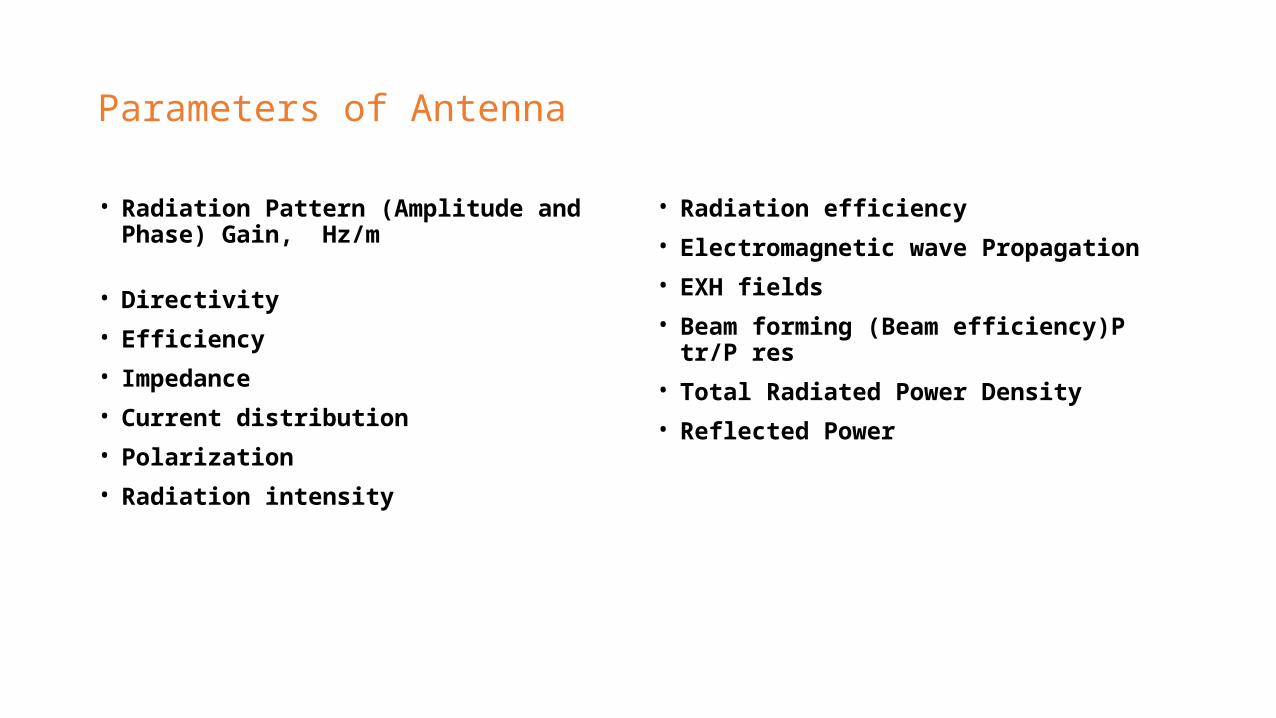
Parameters of Antenna
• Radiation Pattern (Amplitude and Phase) Gain, Hz/m
• Directivity• Efficiency• Impedance• Current distribution• Polarization• Radiation intensity
• Radiation efficiency• Electromagnetic wave Propagation• EXH fields• Beam forming (Beam efficiency)P tr/P res• Total Radiated Power Density• Reflected Power
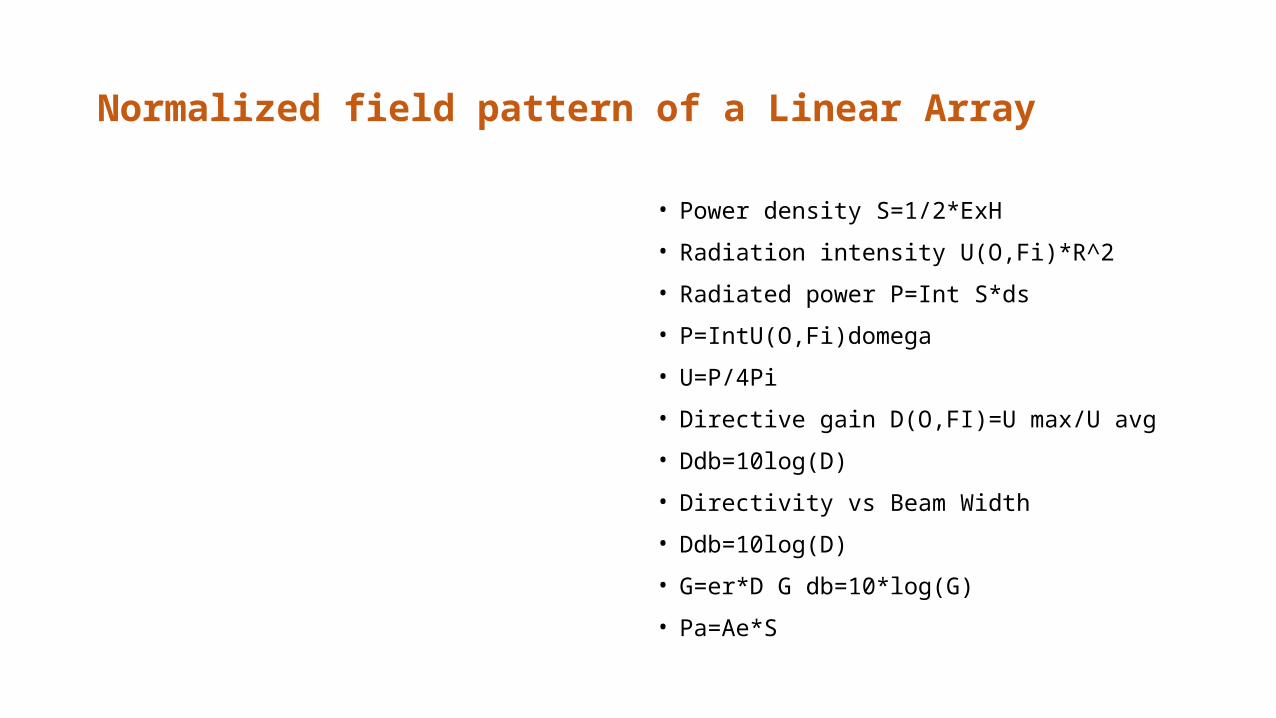
Normalized field pattern of a Linear Array
• Power density S=1/2*ExH
• Radiation intensity U(O,Fi)*R^2
• Radiated power P=Int S*ds
• P=IntU(O,Fi)domega
• U=P/4Pi
• Directive gain D(O,FI)=U max/U avg
• Ddb=10log(D)
• Directivity vs Beam Width
• Ddb=10log(D)
• G=er*D G db=10*log(G)
• Pa=Ae*S
Smart Antenna
• SIR<SNR;• Smart antennas more directional than omnidirectional
antennas• Smart antennas are able to focus their energy toward
the intended users• (base stations can be placed further apart)• Smart antenna systems is security• Smart antenna beam forming is computationally
intensive, which means that smart antenna base stations must be equipped with the very powerful digital signal processing
• Smart antennas have sensor necessary for human ear.• (Humans the ears transducers that convert acoustic
waves into electrochemical impulse, antenna elements convert electromagnetic waves to electrical impulse)
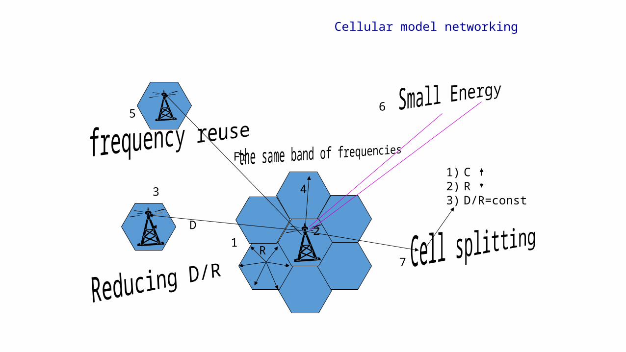
Cellular model networking
4
D
R
1) C2) R3) D/R=const
12
3
5
Fr
6
7
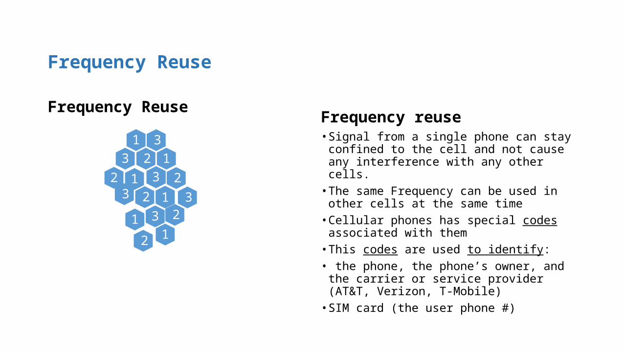
Frequency Reuse
Frequency Reuse
3123 1
33
231
12 1
233
1
32
2
1
Frequency reuse• Signal from a single phone can stay confined to
the cell and not cause any interference with any other cells.
• The same Frequency can be used in other cells at the same time
• Cellular phones has special codes associated with them
• This codes are used to identify:• the phone, the phone’s owner, and the carrier
or service provider (AT&T, Verizon, T-Mobile)• SIM card (the user phone #)
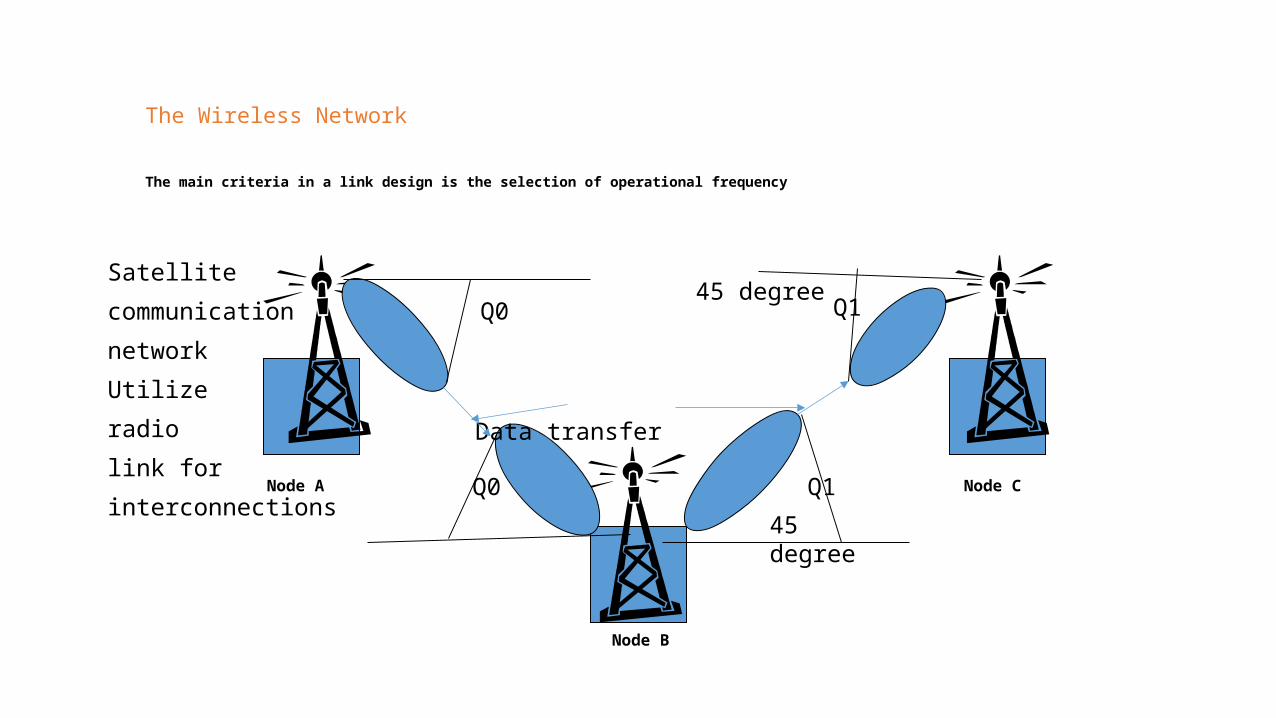
The Wireless Network
The main criteria in a link design is the selection of operational frequency
Satellite
communication
network
Utilize
radio
link for
interconnectionsNode A
Node B
Node C
Q0
Q0
Q1
Q1
45 degree
45 degree
Data transfer
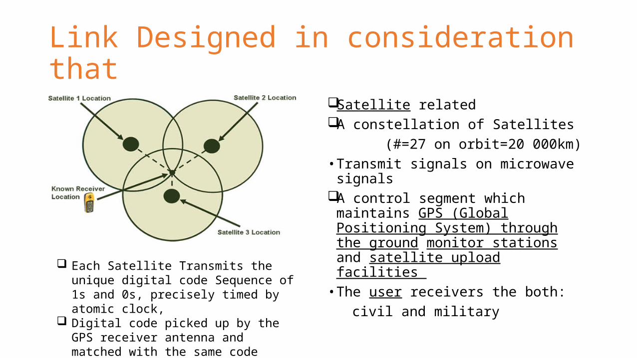
Link Designed in consideration that
Satellite related A constellation of Satellites (#=27 on orbit=20 000km)• Transmit signals on microwave
signalsA control segment which maintains
GPS (Global Positioning System) through the ground monitor stations and satellite upload facilities
• The user receivers the both: civil and military
Each Satellite Transmits the unique digital code Sequence of 1s and 0s, precisely timed by atomic clock,
Digital code picked up by the GPS receiver antenna and matched with the same code sequence generated inside the receiver
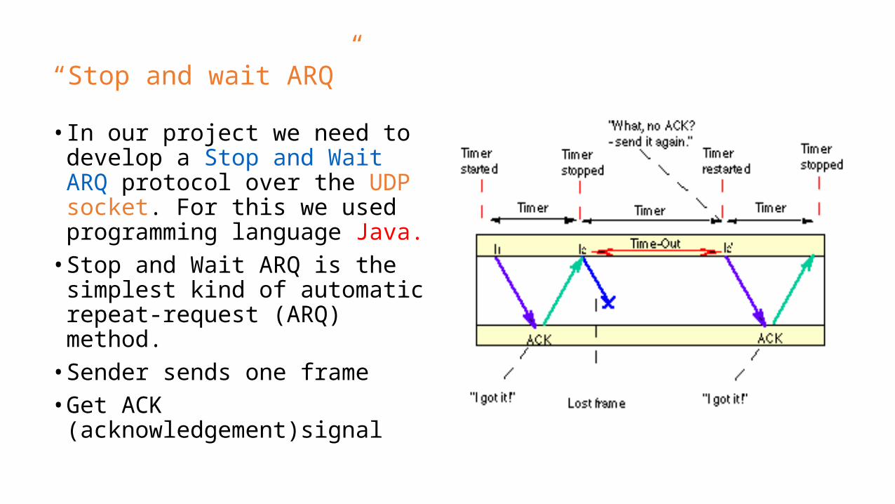
“Stop and wait ARQ”
• In our project we need to develop a Stop and Wait ARQ protocol over the UDP socket. For this we used programming language Java.
• Stop and Wait ARQ is the simplest kind of automatic repeat-request (ARQ) method.
• Sender sends one frame• Get ACK (acknowledgement)signal

package server;import java.io.*;import java.net.*;public class server {
public static void main()throws Exception {
}int port;int maxQueue;InetAddress localAddress;
String clientSentence;Socket.getInput
String capitalizedSentence;ServerSocket welcomeSocket = new ServerSocket (1045);while (true)}
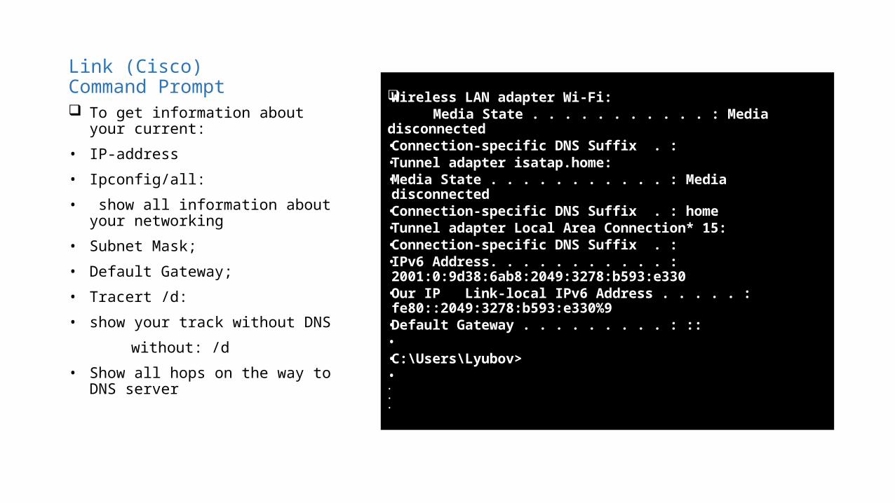
Link (Cisco)Command Prompt
Wireless LAN adapter Wi-Fi: Media State . . . . . . . . . . . : Media disconnected• Connection-specific DNS Suffix . :• Tunnel adapter isatap.home:• Media State . . . . . . . . . . . : Media disconnected• Connection-specific DNS Suffix . : home• Tunnel adapter Local Area Connection* 15:• Connection-specific DNS Suffix . :• IPv6 Address. . . . . . . . . . . :
2001:0:9d38:6ab8:2049:3278:b593:e330• Our IP Link-local IPv6 Address . . . . . :
fe80::2049:3278:b593:e330%9• Default Gateway . . . . . . . . . : ::• • C:\Users\Lyubov>• • • •
To get information about your current:
• IP-address
• Ipconfig/all:
• show all information about your networking
• Subnet Mask;
• Default Gateway;
• Tracert /d:
• show your track without DNS
without: /d
• Show all hops on the way to DNS server
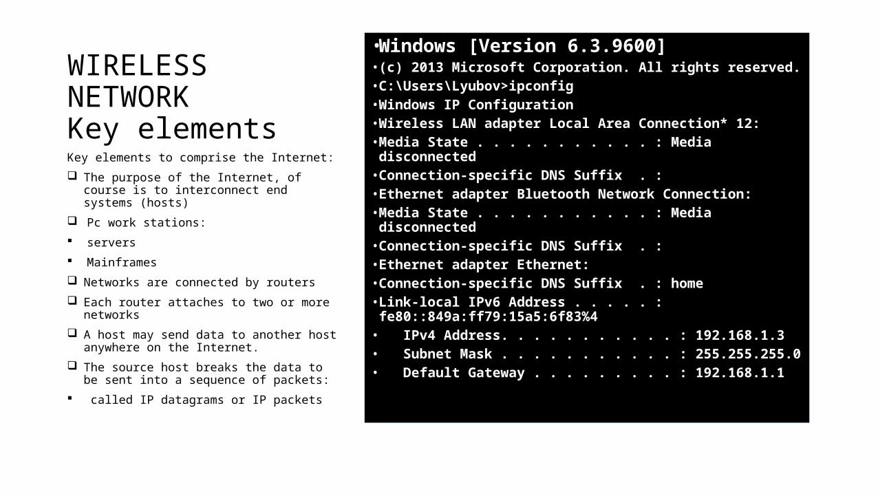
WIRELESS NETWORKKey elements
• Windows [Version 6.3.9600]• (c) 2013 Microsoft Corporation. All rights reserved.• C:\Users\Lyubov>ipconfig• Windows IP Configuration• Wireless LAN adapter Local Area Connection* 12:• Media State . . . . . . . . . . . : Media disconnected• Connection-specific DNS Suffix . :• Ethernet adapter Bluetooth Network Connection:• Media State . . . . . . . . . . . : Media disconnected• Connection-specific DNS Suffix . :• Ethernet adapter Ethernet:• Connection-specific DNS Suffix . : home• Link-local IPv6 Address . . . . . :
fe80::849a:ff79:15a5:6f83%4• IPv4 Address. . . . . . . . . . . : 192.168.1.3• Subnet Mask . . . . . . . . . . . : 255.255.255.0• Default Gateway . . . . . . . . . : 192.168.1.1
Key elements to comprise the Internet:
The purpose of the Internet, of course is to interconnect end systems (hosts)
Pc work stations:
servers
Mainframes
Networks are connected by routers
Each router attaches to two or more networks
A host may send data to another host anywhere on the Internet.
The source host breaks the data to be sent into a sequence of packets:
called IP datagrams or IP packets
Link (Cisco)
• Ipconfig (find IP address) Ip Address: 192.168.1.105
• ping: connection with DNS Subnet mask: 255.255.255.0
• Tranert/d can find the addr-s
• of the nodes Default Gateway:192.168.1.1
Multiple Access Technique
Multiple Access scheme must be able to optimize the following parameters:Satellite Radiated PowerRF spectrumConnectivityAdaptability to traffic different types and networkEconomicsGround Station complexitySecrecy for some applications

OFDMA
ejw0t
ejw1t
ejwN-1T
e^-jwotg^*(-t)0
g^(-t)1
g^*(-t)N-1
e^-jw1t
e^-jw(N-t
Orthogonality: integral (-infinity, infinity)xp(t)*xq(t)*dt=0 (p not =q) Orthogonal Carriers S(t)=RE {SUM xk*Ae^j2pi*k*f0*t} T=1/f0
F1,f2,fn
The perspectives of development of Wireless Communications utilizing MIMO technology
• Increasing the bandwidth and increasing the quality of service
at new system LTE-> directly connected with the development of MIMO technology;
• MIMO technology allow decrease the # of errors, without the decreasing the speed of data;
• The history of MIMO very short (the first patent registered at 1985).
MIMO Technology was used:
• for the first time at UMTS for high speed technology when transforming the IP at downlink to increase the Vmax of date from 10.8 Mit/sec to 20 Mbit/sec
• shorten time frame (Tint=2msec)
• multi code
• adaptive Modulation and code
• shorten HARQ (N channel with Stop And Wait Protocol)
• antenna MIMO
• perspective Receiver UMTS
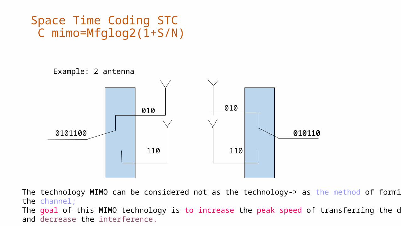
Space Time Coding STC C mimo=Mfglog2(1+S/N)
Example: 2 antenna
0101100
010 010
110
010110
110
010110
The technology MIMO can be considered not as the technology-> as the method of forming the channel;The goal of this MIMO technology is to increase the peak speed of transferring the date and decrease the interference.
MIMO
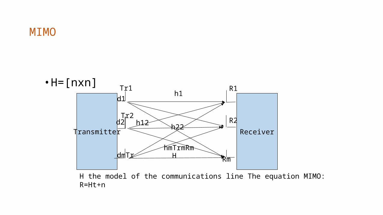
• H=[nxn]
Transmitter
H Rm
H the model of the communications line The equation MIMO: R=Ht+n
d1
d2
dmTr
R1
R2
h1
h12
hmTrmRm
h22Receiver
Tr1
Tr2
Antenna MIMO technology
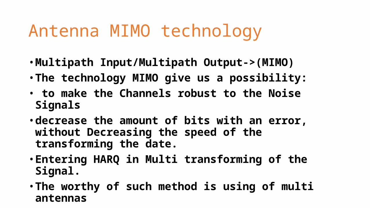
• Multipath Input/Multipath Output->(MIMO)• The technology MIMO give us a possibility:• to make the Channels robust to the Noise Signals• decrease the amount of bits with an error, without Decreasing the
speed of the transforming the date. • Entering HARQ in Multi transforming of the Signal.• The worthy of such method is using of multi antennas
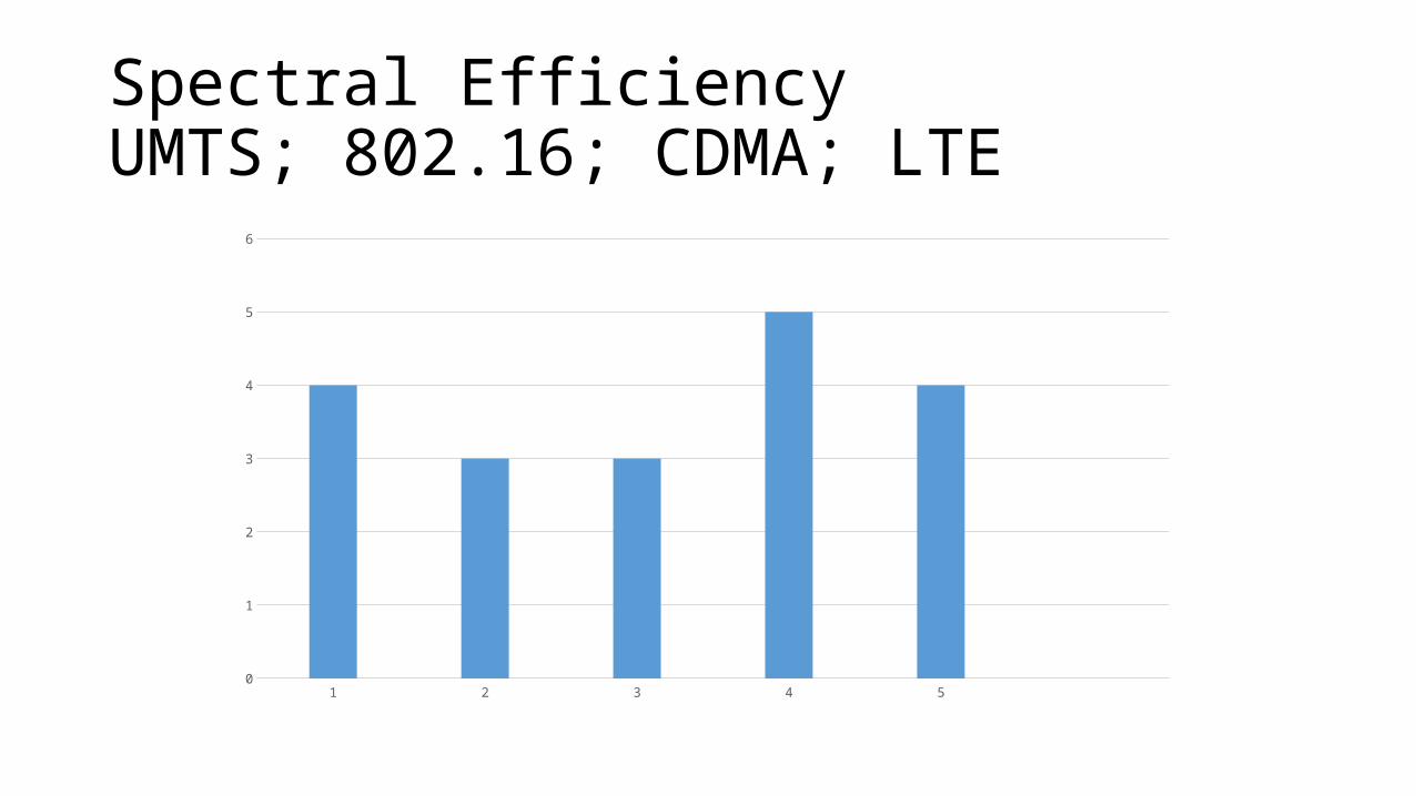
Spectral EfficiencyUMTS; 802.16; CDMA; LTE
1 2 3 4 50
1
2
3
4
5
6
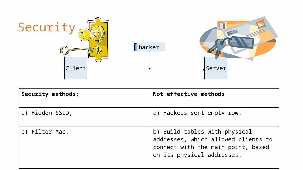
Security
Security methods: Not effective methods
a) Hidden SSID; a) Hackers sent empty row;
b) Filter Mac. b) Build tables with physical addresses, which allowed clients to connect with the main point, based on its physical addresses.
Client Server
hacker
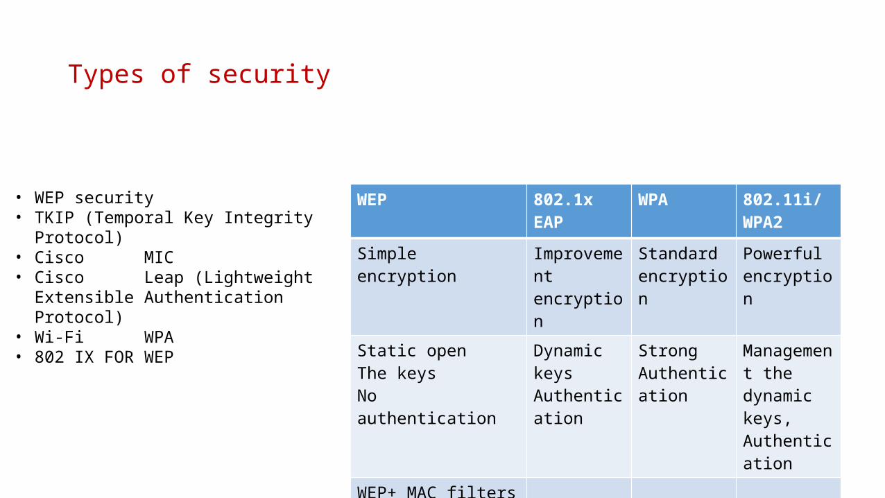
Types of security
WEP 802.1xEAP
WPA 802.11i/WPA2
Simple encryption Improvementencryption
Standardencryption
Powerful encryption
Static openThe keysNo authentication
Dynamic keysAuthentication
Strong Authentication
Management thedynamic keys,Authentication
WEP+ MAC filters
• WEP security• TKIP (Temporal Key Integrity Protocol)• Cisco MIC• Cisco Leap (Lightweight Extensible
Authentication Protocol)• Wi-Fi WPA• 802 IX FOR WEP
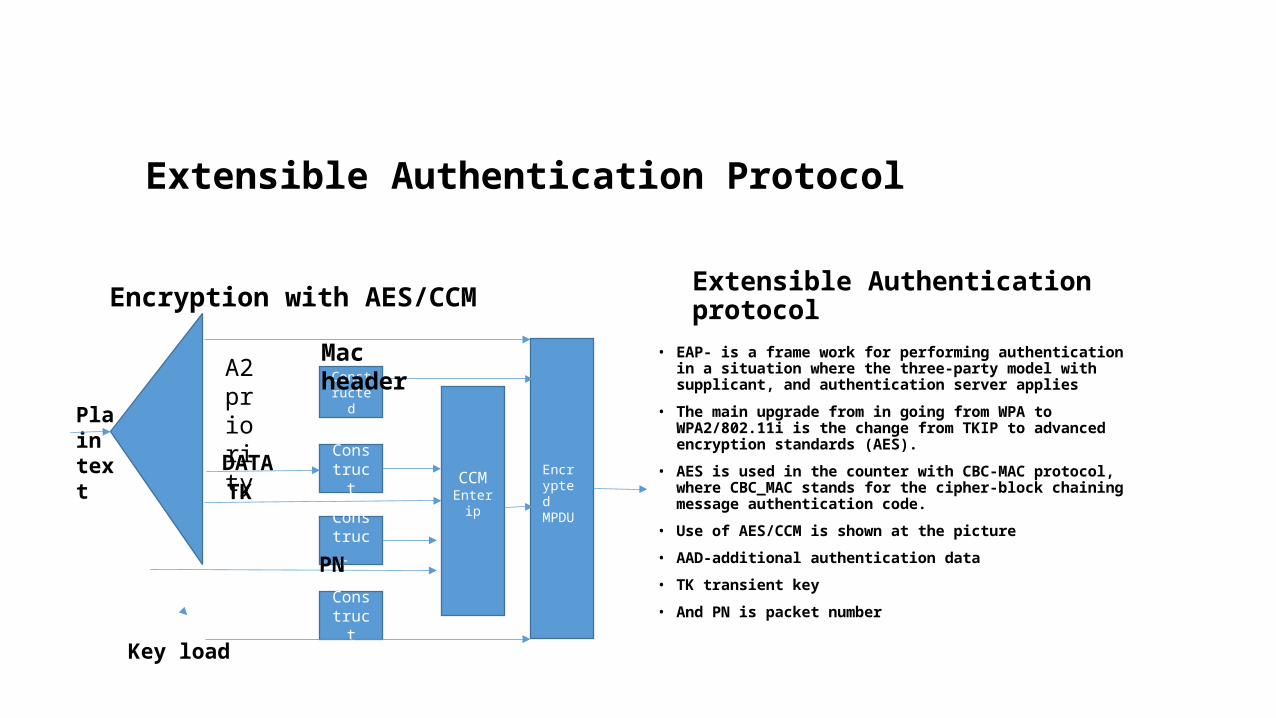
Extensible Authentication Protocol
Encryption with AES/CCM
• EAP- is a frame work for performing authentication in a situation where the three-party model with supplicant, and authentication server applies
• The main upgrade from in going from WPA to WPA2/802.11i is the change from TKIP to advanced encryption standards (AES).
• AES is used in the counter with CBC-MAC protocol, where CBC_MAC stands for the cipher-block chaining message authentication code.
• Use of AES/CCM is shown at the picture
• AAD-additional authentication data
• TK transient key
• And PN is packet number
Extensible Authentication protocol
Constructed
Construct
Constr
uct
Construct
CCMEnter ip
Plain text
Mac headerA2 priority
Encrypted MPDU
DATA
PN
Key load
TK
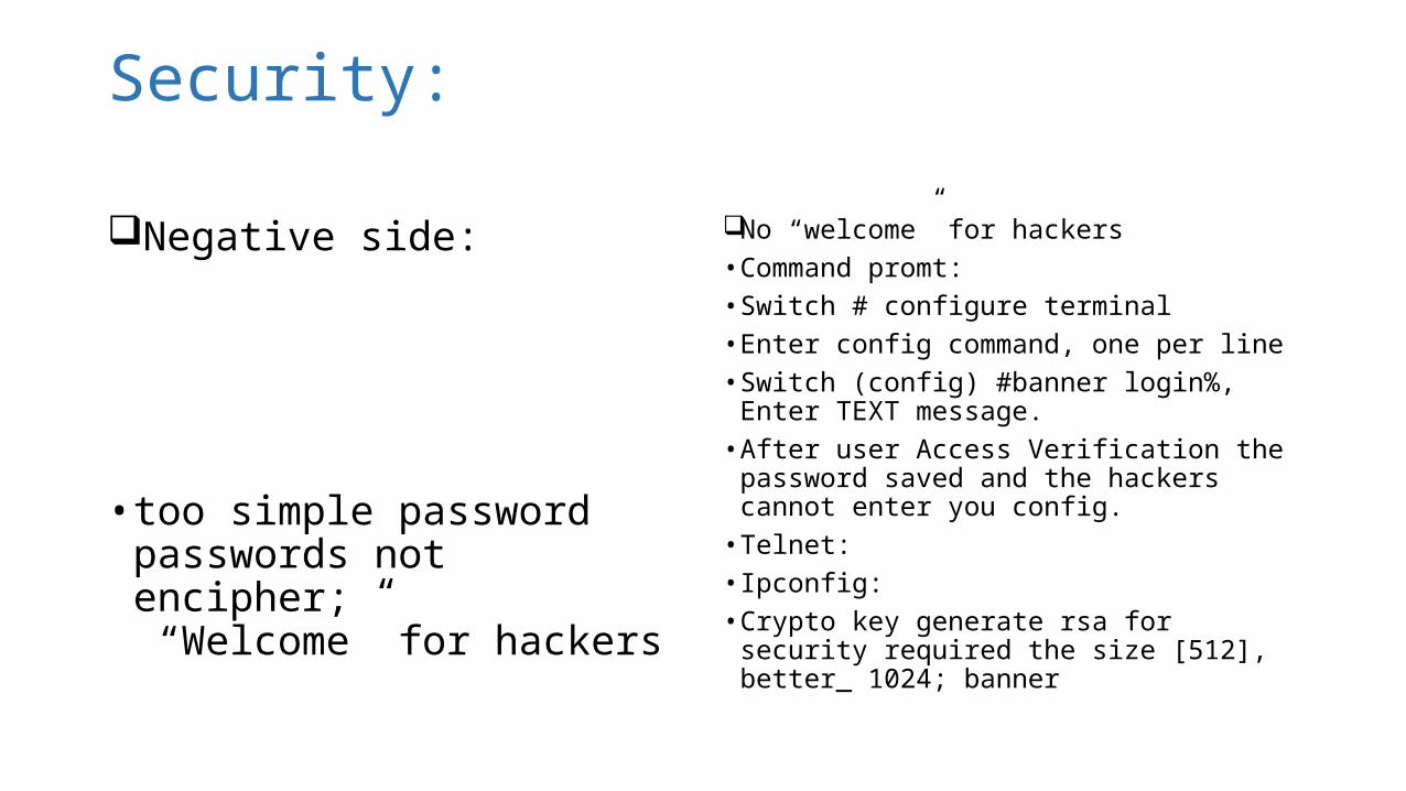
Security:
Negative side:
• too simple passwordpasswords not encipher; “Welcome” for hackers
No “welcome” for hackers• Command promt:• Switch # configure terminal• Enter config command, one per line• Switch (config) #banner login%, Enter TEXT
message. • After user Access Verification the password
saved and the hackers cannot enter you config.
• Telnet:• Ipconfig:• Crypto key generate rsa for security required
the size [512], better_ 1024; banner
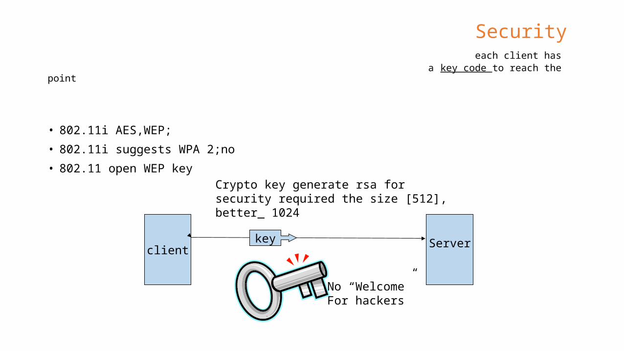
Security each client has a key code to reach the point
• 802.11i AES,WEP;
• 802.11i suggests WPA 2;no
• 802.11 open WEP key
clientkey
No “Welcome” For hackers
Crypto key generate rsa for security required the size [512], better_ 1024
Server


![IEEE SouthEastern Michigan – Wavelengths...Section Adviser Don Bramlett d.bramlett-AT-ieee.org Past-Ch Kimball Williams k.williams-AT-ieee.org Chapter 04 [CH04050] (AP03) AP03 Antennas](https://img.pdfslide.us/doc/110x75/60af67e8012b0e799e79facc/ieee-southeastern-michigan-a-wavelengths-section-adviser-don-bramlett-dbramlett-at-ieeeorg.jpg)