Embed Size (px)
Citation preview
WIRELESS COMMUNICATIONSJULY 2018
CHRIS LOMONT
BASIC PHYSICS
• Voltage is a potential; it pulls/pushes charged items
• Oscillating voltage makes electrons oscillate in conductors
• Oscillating electrons create an
oscillating electric field
• Changing electric fields makes a
changing perpendicular magnetic field
• These create an electromagnetic wave
ELECTROMAGNETIC WAVES
• Wave propagates at the speed of light
• Speed 𝑐 ≈ 3 × 10⁸ m/s = 300 m/us
• Wavelength 𝜆 is distance between humps
• Frequency 𝑓 is how many times per second hump passes
• 𝜆𝑓 = 𝑐
• Amplitide is height (strength) of the wave
• Inverse square law for static electric field: 𝐸 𝑥0 =1
4𝜋𝜖0
𝑞1
𝑥1−𝑥0 2
• Liénard–Wiechert potential for moving charge
• Relativistically correct time-varying electromagnetic field for charge in motion
• 𝐸 𝑟, 𝑡 =1
4𝜋𝜖0
𝑞(𝑛−𝛽)
𝛾2 1−𝑛𝛽 3 𝑟−𝑟𝑠2 +
𝑞𝑛× 𝑛−𝛽 × ሶ𝛽
𝑐 1−𝑛𝛽 3|𝑟−𝑟𝑠|
• Note last term is not inverse square! Without this radio would be useless!
ELECTROMAGNETIC WAVES
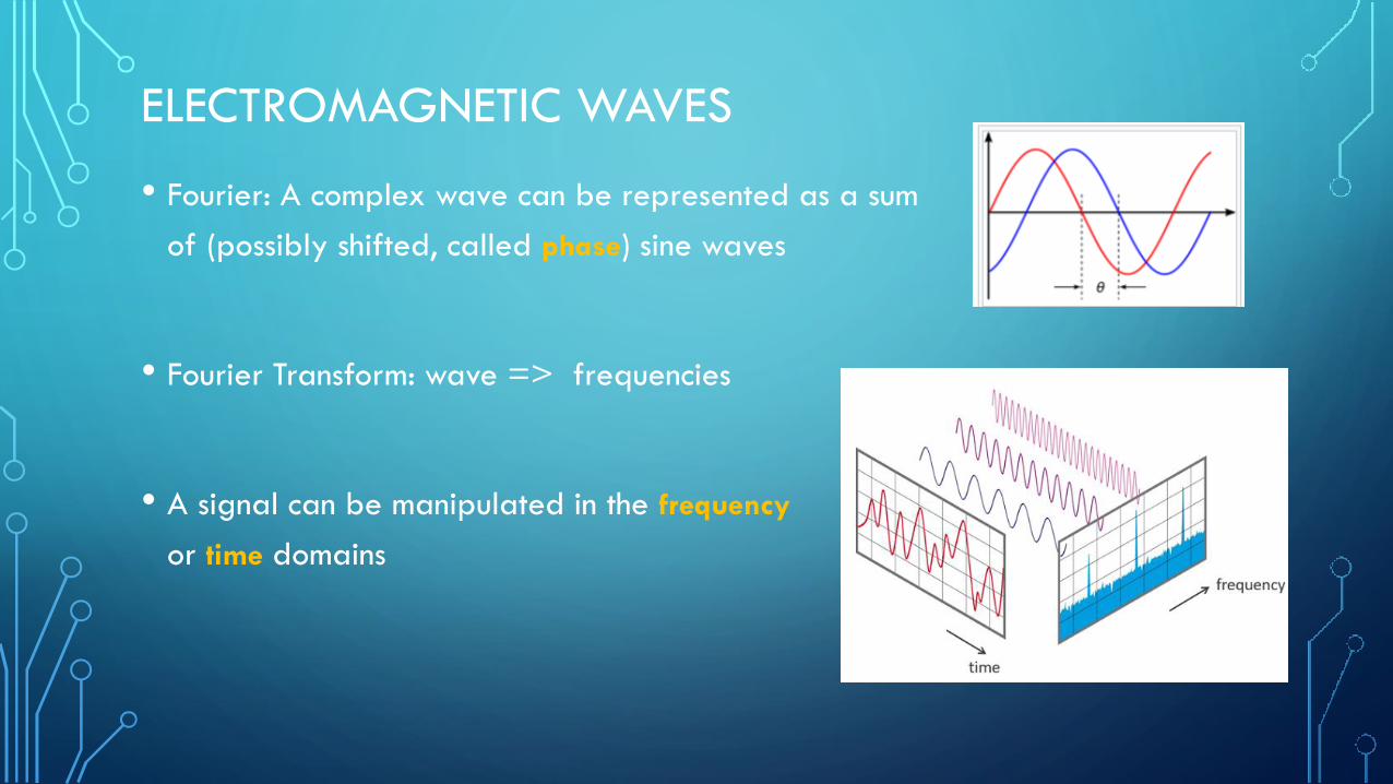
• Fourier: A complex wave can be represented as a sum
of (possibly shifted, called phase) sine waves
• Fourier Transform: wave => frequencies
• A signal can be manipulated in the frequency
or time domains
ELECTROMAGNETIC WAVES
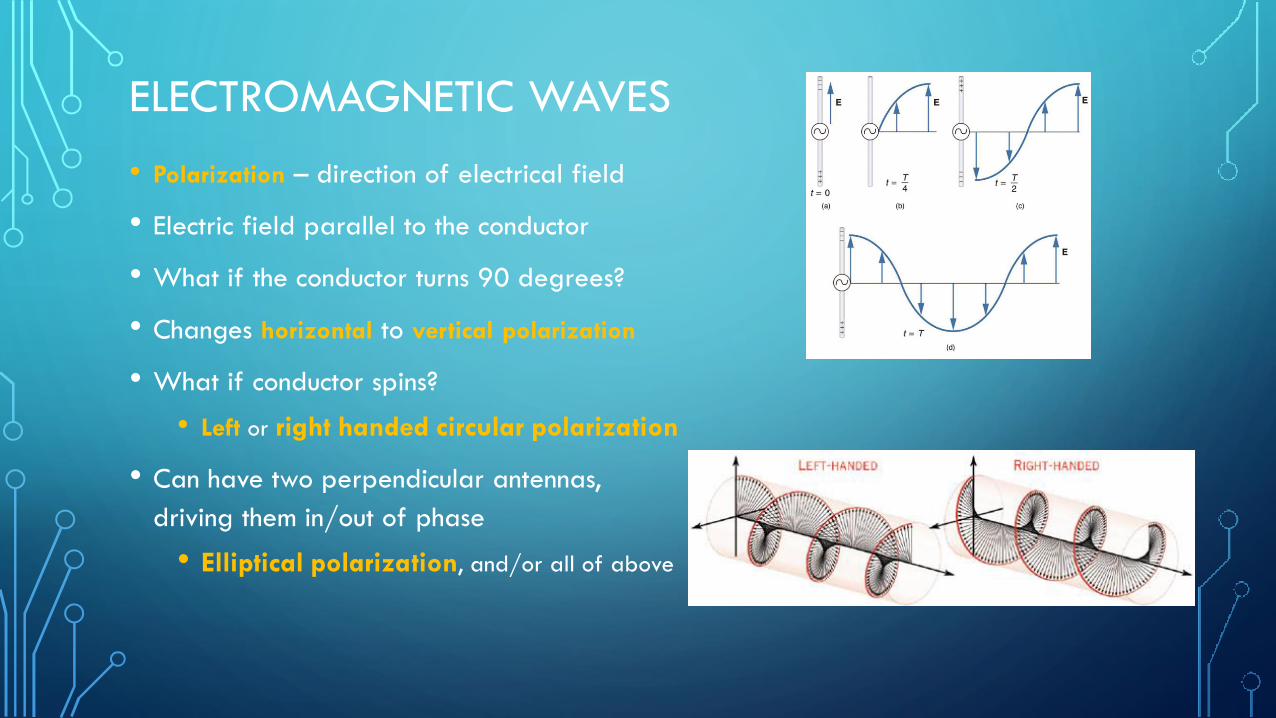
• Polarization – direction of electrical field
• Electric field parallel to the conductor
• What if the conductor turns 90 degrees?
• Changes horizontal to vertical polarization
• What if conductor spins?
• Left or right handed circular polarization
• Can have two perpendicular antennas,
driving them in/out of phase
• Elliptical polarization, and/or all of above

ELECTROMAGNETIC WAVES
• Wave properties used to send data:
• Frequency
• Amplitude
• Phase
• Polarization
RADIO FREQUENCIES
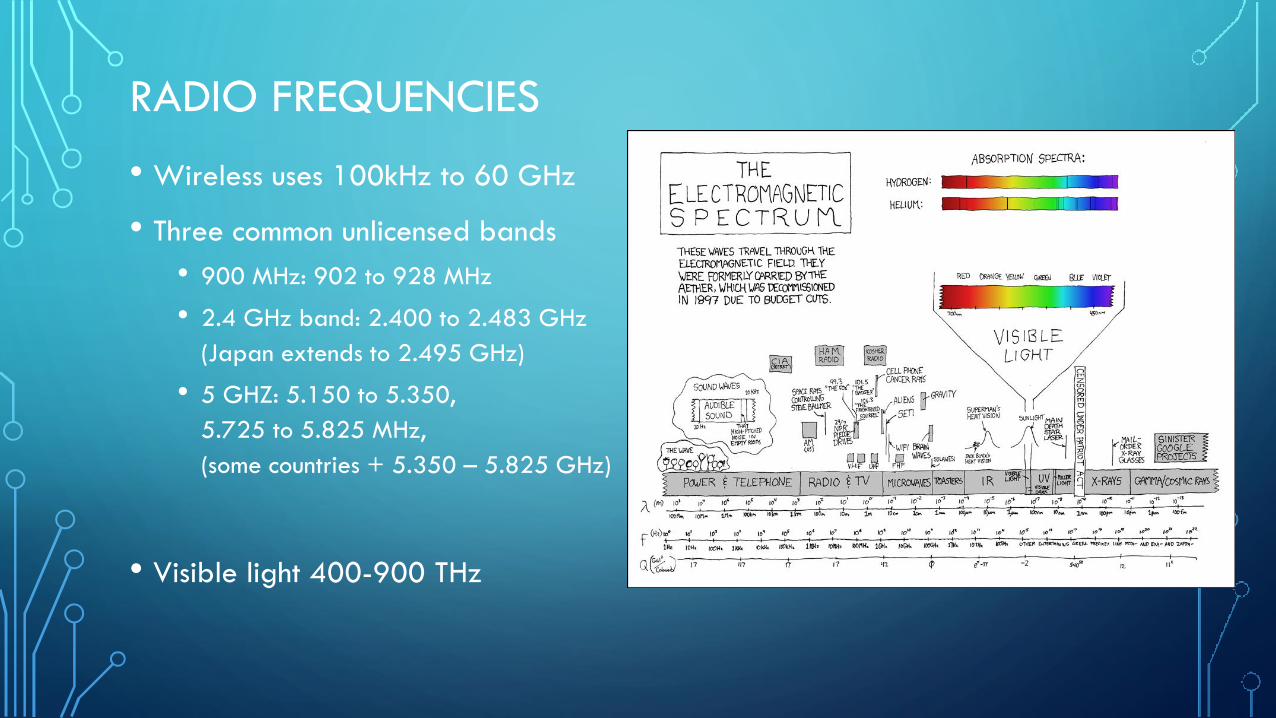
• Wireless uses 100kHz to 60 GHz
• Three common unlicensed bands
• 900 MHz: 902 to 928 MHz
• 2.4 GHz band: 2.400 to 2.483 GHz
(Japan extends to 2.495 GHz)
• 5 GHZ: 5.150 to 5.350,
5.725 to 5.825 MHz,
(some countries + 5.350 – 5.825 GHz)
• Visible light 400-900 THz
RADIO FREQUENCIES
WIRELESS PROPAGATION
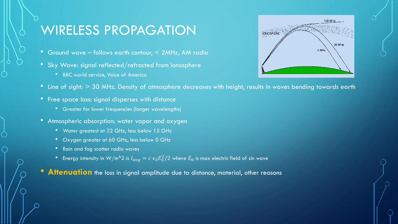
• Ground wave – follows earth contour, < 2MHz, AM radio
• Sky Wave: signal reflected/refracted from ionosphere
• BBC world service, Voice of America
• Line of sight: > 30 MHz. Density of atmosphere decreases with height, results in waves bending towards earth
• Free space loss: signal disperses with distance
• Greater for lower frequencies (longer wavelengths)
• Atmospheric absorption: water vapor and oxygen
• Water greatest at 22 GHz, less below 15 GHz
• Oxygen greater at 60 GHz, less below 0 GHz
• Rain and fog scatter radio waves
• Energy intensity in W/m^2 is 𝐼𝑎𝑣𝑔 = 𝑐 𝜖0𝐸02/2 where 𝐸0 is max electric field of sin wave
• Attenuation the loss in signal amplitude due to distance, material, other reasons

INTERACTION WITH MATERIALS
• Wave causes electrons to vibrate
• These then re-emit radio waves
• Causes refraction, reflection
• Some increases atomic lattice vibrations
• Radio energy lost to heat
• Metals have a lot of free electrons
• Absorb most
• Tightly bound electrons, no resonance near
transmission, appears the most “clear”
• Radio waves deflect like light when changing media
ANTENNAS - LENGTH
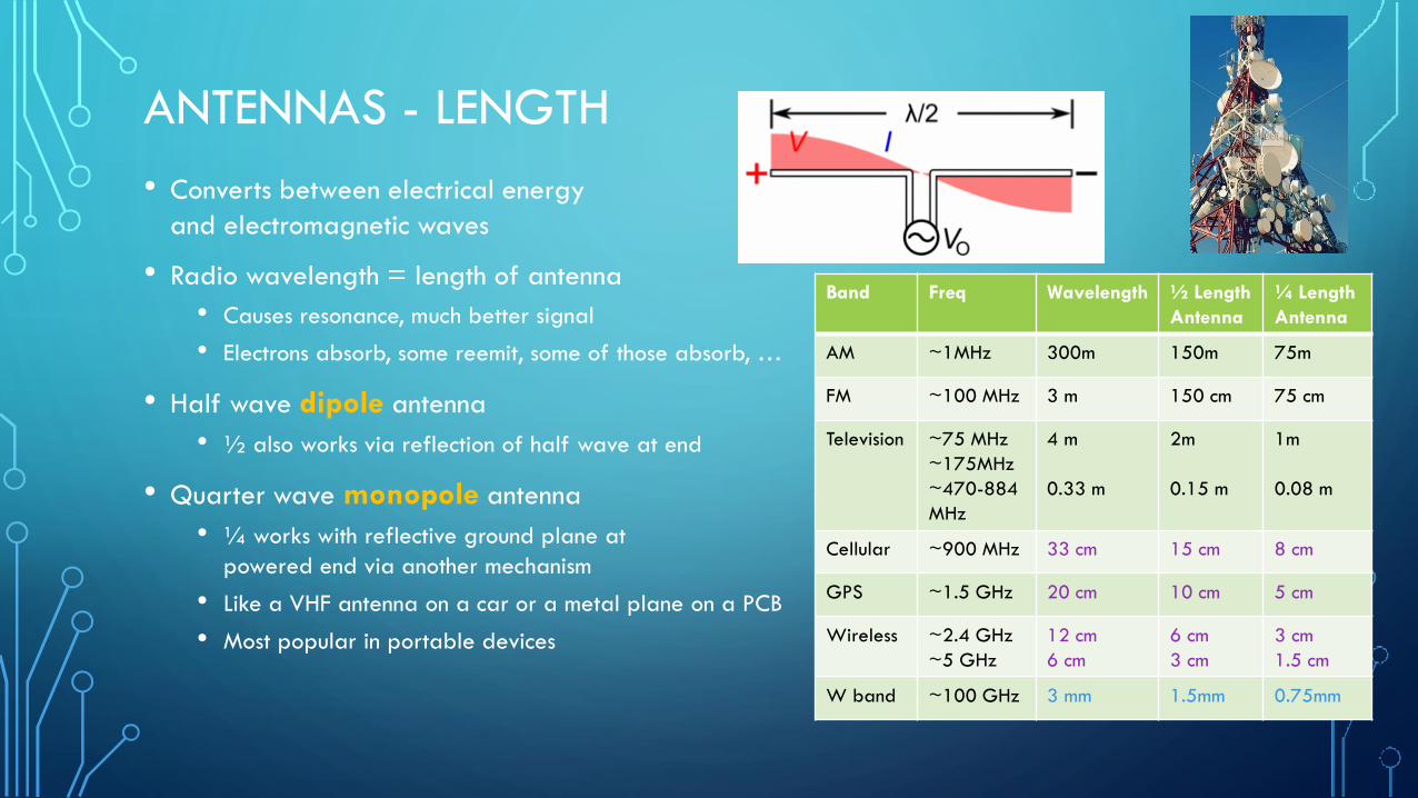
• Converts between electrical energy
and electromagnetic waves
• Radio wavelength = length of antenna
• Causes resonance, much better signal
• Electrons absorb, some reemit, some of those absorb, …
• Half wave dipole antenna
• ½ also works via reflection of half wave at end
• Quarter wave monopole antenna
• ¼ works with reflective ground plane at
powered end via another mechanism
• Like a VHF antenna on a car or a metal plane on a PCB
• Most popular in portable devices
Band Freq Wavelength ½ Length
Antenna
¼ Length
Antenna
AM ~1MHz 300m 150m 75m
FM ~100 MHz 3 m 150 cm 75 cm
Television ~75 MHz
~175MHz
~470-884
MHz
4 m
0.33 m
2m
0.15 m
1m
0.08 m
Cellular ~900 MHz 33 cm 15 cm 8 cm
GPS ~1.5 GHz 20 cm 10 cm 5 cm
Wireless ~2.4 GHz
~5 GHz
12 cm
6 cm
6 cm
3 cm
3 cm
1.5 cm
W band ~100 GHz 3 mm 1.5mm 0.75mm

DECIBELS
• Decibels measure a ratio of power between two things on a log scale
𝑑𝐵 = 10 × log10𝑃1𝑃0
• Use log since numbers vary by many orders of magnitude
• Larger numbers are more power
• Each 3dB is approximately a doubling (or halving) of power
• For antennas and wireless, generally 𝑃1 and 𝑃0 measure power in Watts
• Often a suffix tells what 𝑃0 is
• dBm : 𝑃0 = 1mW
• dBi : antenna gain versus an isotropic (uniform) antenna
• dBd: antenna gain versus a dipole antenna
• Can add to get total gain/loss (attenuation)
801.11 network loss
Plasterboard 3dB
Glass wall with metal frame 6dB
Cinder block wall 4dB
Office window 3dB
Metal door 6dB
Metal door in brick wall 12dB
ANTENNAS - GEOMETRY
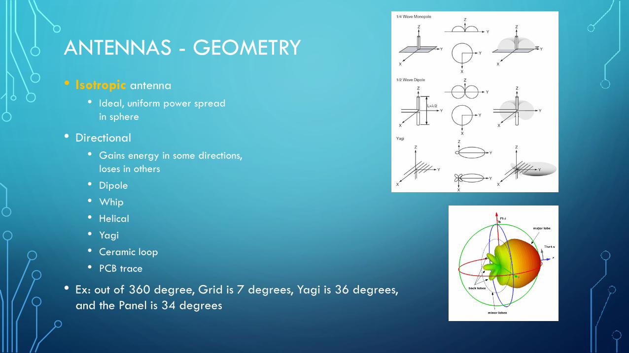
• Isotropic antenna
• Ideal, uniform power spread
in sphere
• Directional
• Gains energy in some directions,
loses in others
• Dipole
• Whip
• Helical
• Yagi
• Ceramic loop
• PCB trace
• Ex: out of 360 degree, Grid is 7 degrees, Yagi is 36 degrees,
and the Panel is 34 degrees
ANTENNAS - GAIN
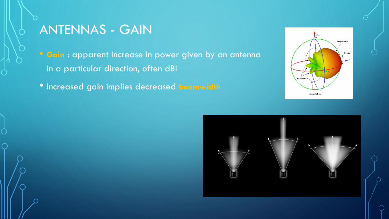
• Gain : apparent increase in power given by an antenna
in a particular direction, often dBi
• Increased gain implies decreased beamwidth
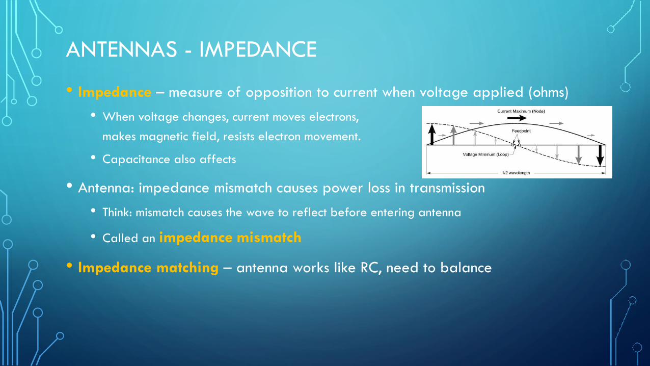
ANTENNAS - IMPEDANCE
• Impedance – measure of opposition to current when voltage applied (ohms)
• When voltage changes, current moves electrons,
makes magnetic field, resists electron movement.
• Capacitance also affects
• Antenna: impedance mismatch causes power loss in transmission
• Think: mismatch causes the wave to reflect before entering antenna
• Called an impedance mismatch
• Impedance matching – antenna works like RC, need to balance

ANTENNAS
• Beam shaping via phase array
• Reciprocity theorem• The following are the same for a given antenna for
transmitting and receiving
• Gain
• Radiation pattern
• Impedance
• Bandwidth
• Resonant Frequency
• Polarization
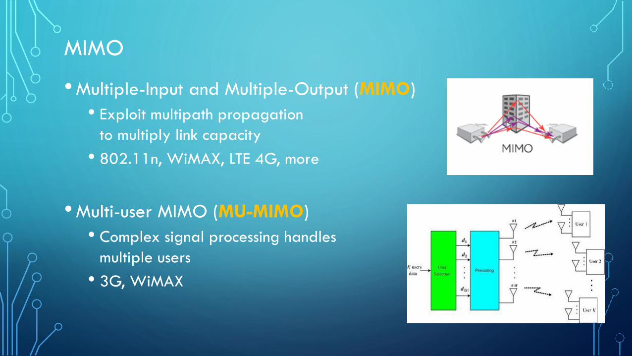
MIMO
•Multiple-Input and Multiple-Output (MIMO)
• Exploit multipath propagation
to multiply link capacity
• 802.11n, WiMAX, LTE 4G, more
•Multi-user MIMO (MU-MIMO)
• Complex signal processing handles
multiple users
• 3G, WiMAX

MODULATION
• Modulation: varying a periodic waveform called the carrier signal with another
signal to encode information
• modem = modulator/demodulator
• AM = amplitude modulation
• FM = frequency modulation
• Data direction:
• Simplex : one way (TV)
• Half duplex : two way, alternate channel use (CB radio)
• Full duplex : two way using two channels (mobile phone)
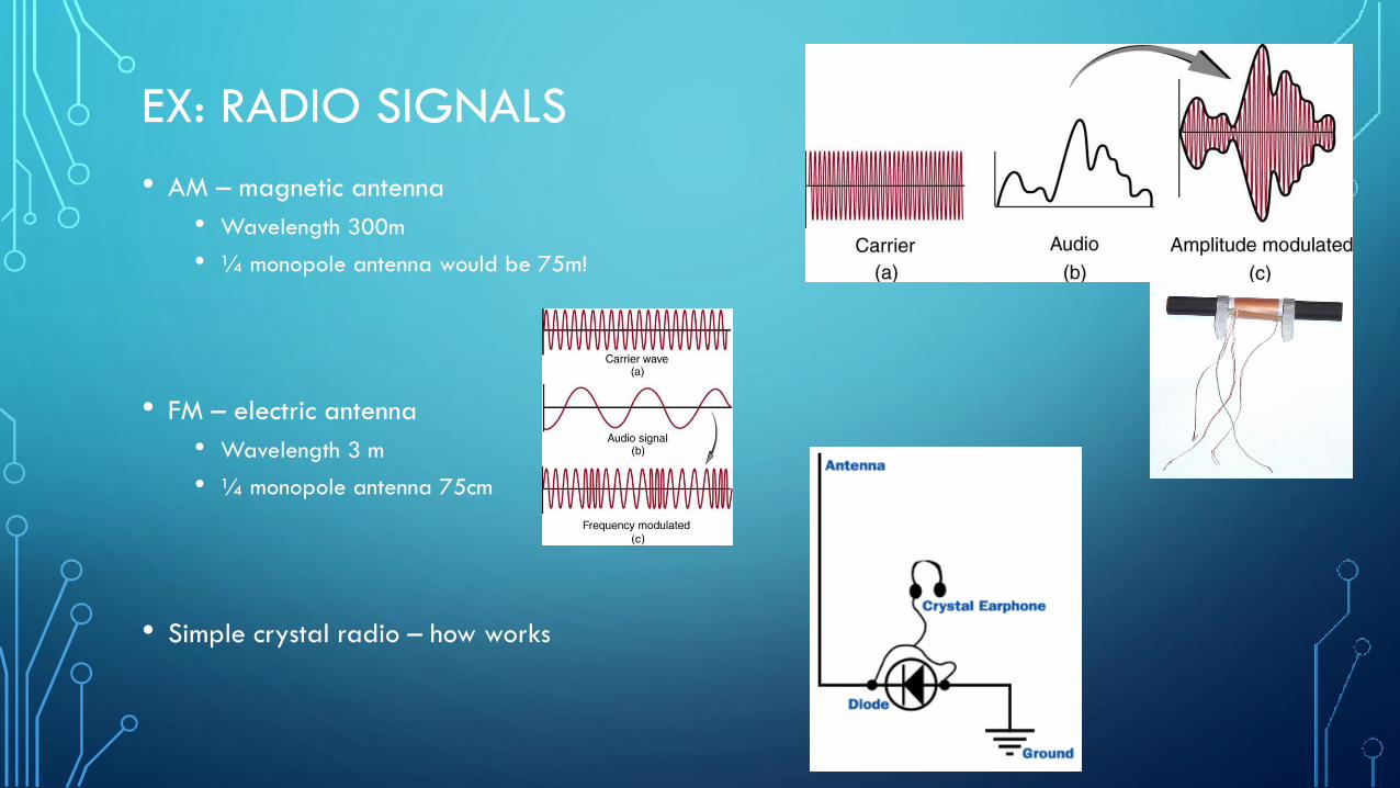
EX: RADIO SIGNALS
• AM – magnetic antenna
• Wavelength 300m
• ¼ monopole antenna would be 75m!
• FM – electric antenna
• Wavelength 3 m
• ¼ monopole antenna 75cm
• Simple crystal radio – how works
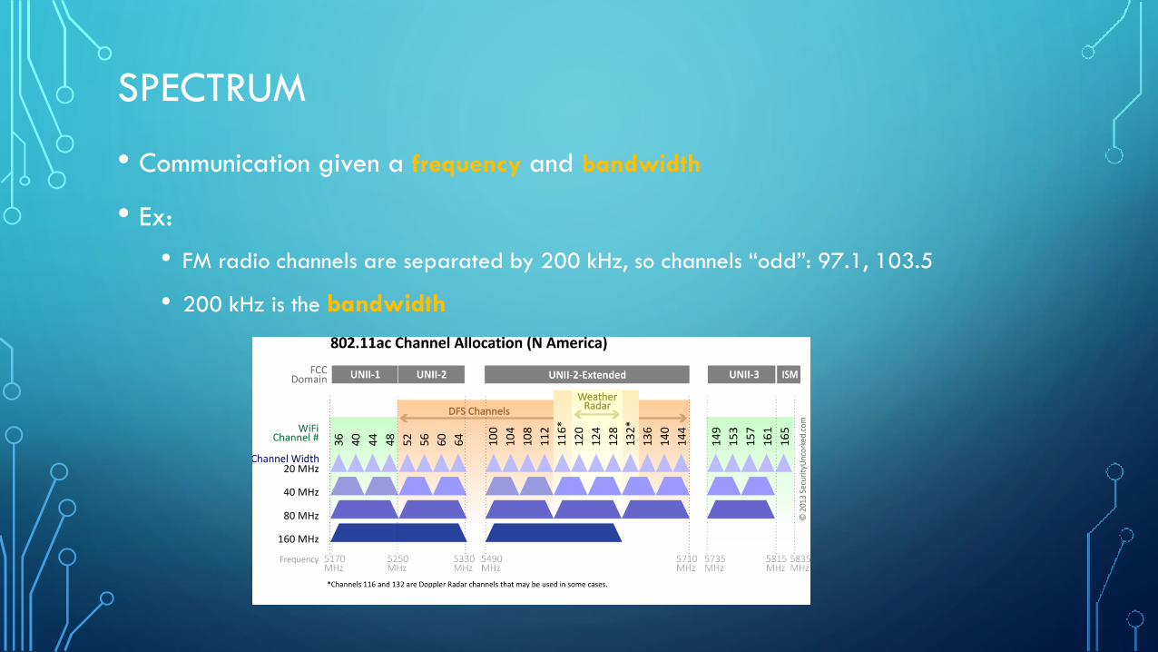
SPECTRUM
• Communication given a frequency and bandwidth
• Ex:
• FM radio channels are separated by 200 kHz, so channels “odd”: 97.1, 103.5
• 200 kHz is the bandwidth
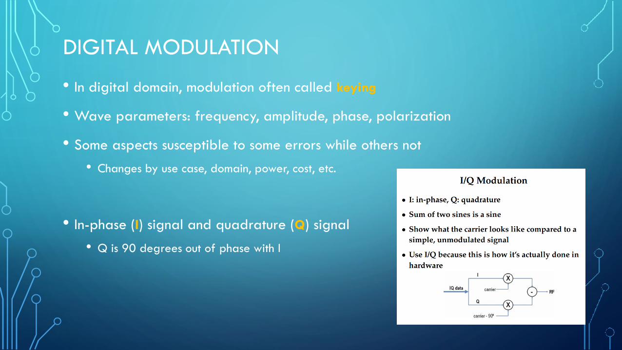
DIGITAL MODULATION
• In digital domain, modulation often called keying
• Wave parameters: frequency, amplitude, phase, polarization
• Some aspects susceptible to some errors while others not
• Changes by use case, domain, power, cost, etc.
• In-phase (I) signal and quadrature (Q) signal
• Q is 90 degrees out of phase with I
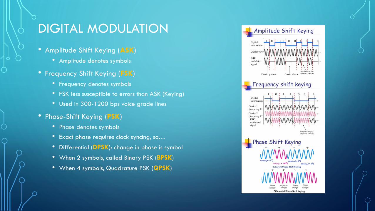
DIGITAL MODULATION
• Amplitude Shift Keying (ASK)
• Amplitude denotes symbols
• Frequency Shift Keying (FSK)
• Frequency denotes symbols
• FSK less susceptible to errors than ASK (Keying)
• Used in 300-1200 bps voice grade lines
• Phase-Shift Keying (PSK)
• Phase denotes symbols
• Exact phase requires clock syncing, so…
• Differential (DPSK): change in phase is symbol
• When 2 symbols, called Binary PSK (BPSK)
• When 4 symbols, Quadrature PSK (QPSK)

DIGITAL MODULATION
• Multi-level PSK (MPSK)
• 9600 baud modems use PSK with 4 bits
• Offset quadrature phase-shift keying (OQPSK)
• limited to 90 degree rotations
• Gaussian Minimum Shift Keying (GMSK)
• Minimum shift for next symbol
• Gaussian filtered to remove sideband noise
(square edges “ring”)
• Used in GSM cellular systems
• Many, many more….

DIGITAL MODULATION
• Want more symbols: so mix phase and amplitude….
• Quadrature Amplitude Modulation (QAM)
• QAM-4, QAM-16, QAM-64, QAM-256, …
• DOCSIS up to QAM-16384, Digital Video 65536, more ?
QAM-4: same performance, twice the bandwidth efficiency of BPSK
• Used in DSL, wireless networks, many more
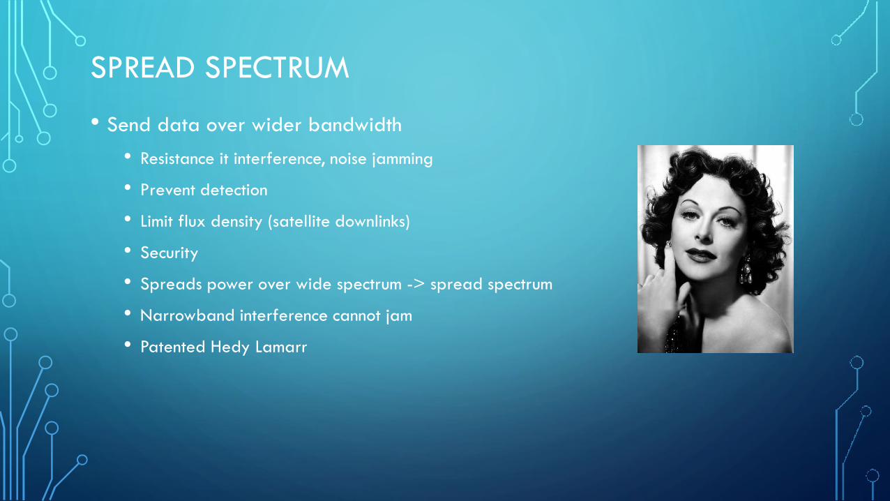
SPREAD SPECTRUM
• Send data over wider bandwidth
• Resistance it interference, noise jamming
• Prevent detection
• Limit flux density (satellite downlinks)
• Security
• Spreads power over wide spectrum -> spread spectrum
• Narrowband interference cannot jam
• Patented Hedy Lamarr

SPREAD SPECTRUM
• Frequency hopping spread spectrum (FHSS)
• Pseudo random frequency hopping, known to transmitter
and receiver
• Bluetooth
• Direct sequence spread spectrum (DSSS):
• Spreading factor: code bits/databit = 10-100 commercial
(FCC min 10), 10,000 for military
• Signal bandwidth > 10x data bandwidth

DIVISION
• Frequency Division Multiple Access (FDMA)
• Multiple users share channel bandwidth, each has very specific frequency
• Requires high performance hardware filters
• Time Division Multiple Access (TDMA)
• Users share same channel, take turns split in time
• Used in 2G
• Time Division Duplex (TDD)
• Allows duplex over single channel via time
• Used in many LTE deployments
• Code Division Multiple Access (CDMA)
• Each user data XORed with unique pseudorandom code,
all users transmit, decoder pulls out each signal
• 8-15 times capacity of analog
• Spread spectrum single sideband
DIVISION
• Orthogonal Frequency Division Multiplexing (OFDM)
• Splits channel into multiple frequencies
• Nearby subchannels encoded using methods to avoid crosstalk, “orthogonal”
• Orthogonal => peak of one is null of other
• Better able to cope with severe channel conditions
• Available band divided into 256 or more subbands
• Each carrier modulated BPSK, QPSK, 16-QAM, 256-QAM, …
• Selective frequency fading
• Used in 802.11a/g, 802.16, HDTV, ADSL, DOCSIS, WLAN, 802.11ax, more

NOISE
• Reflection
• Large surface relative to wavelength
• May have phase shift
• May cancel original or increase it
• Diffraction around edges
• Edge of impenetrable body large relative to wavelength
• Scattering
• Obstacle on order of wavelength, like a lightpost
• If no line of sight (LOS), diffraction and scattering are
primary means of reception
NOISE
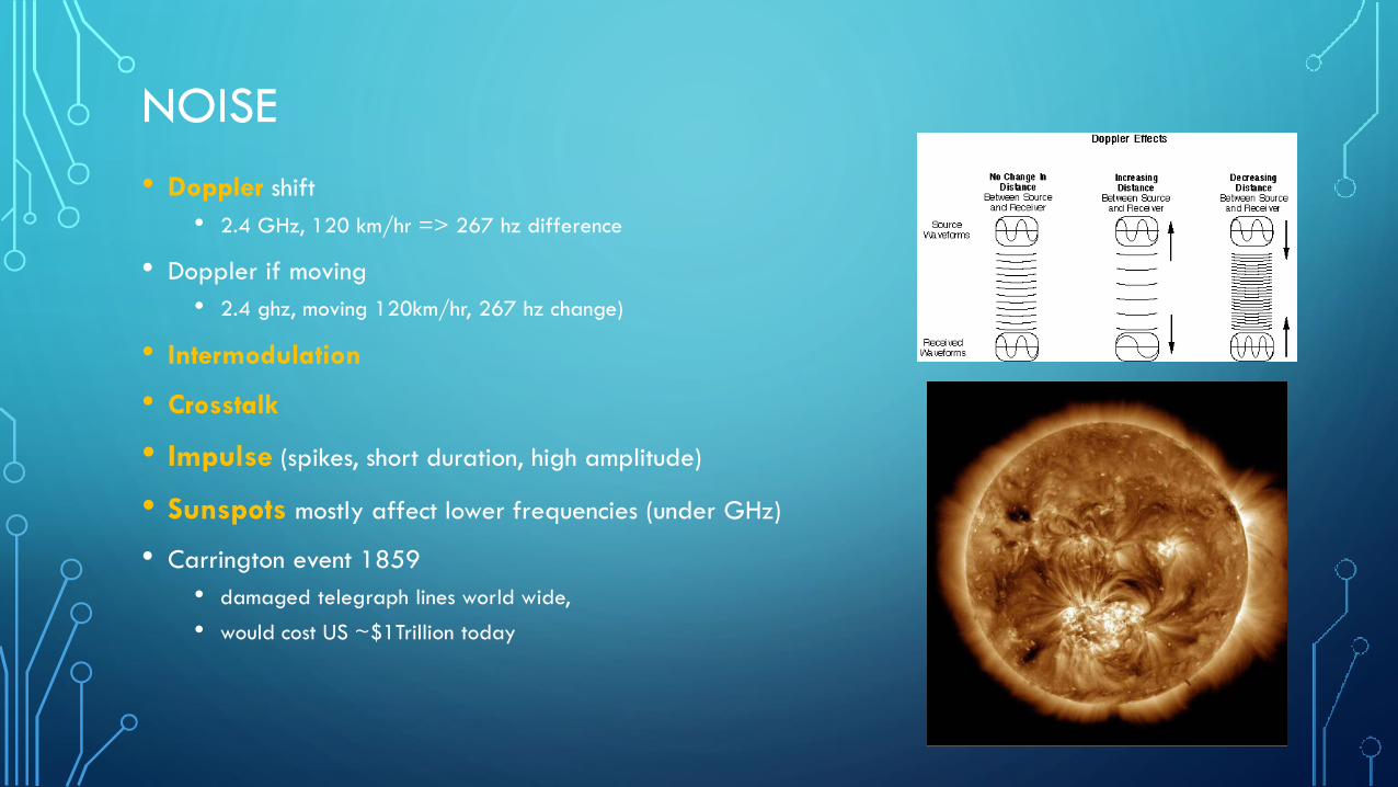
• Doppler shift
• 2.4 GHz, 120 km/hr => 267 hz difference
• Doppler if moving
• 2.4 ghz, moving 120km/hr, 267 hz change)
• Intermodulation
• Crosstalk
• Impulse (spikes, short duration, high amplitude)
• Sunspots mostly affect lower frequencies (under GHz)
• Carrington event 1859
• damaged telegraph lines world wide,
• would cost US ~$1Trillion today
THERMAL NOISE
• Thermal – heat is vibrating atoms, vibrating atoms emit radio waves
• antennas heat things, how microwave works
• Uniformly distributed, white noise
• Thermal noise = 𝑘𝑇 Watts/Hz
• 𝑘 = Boltzmann constant = 1.38 x 10^-23 Joules/Kelvin
• 𝑇 = absolute temperature in Kelvins
• Ex: 10 MHz receiver at 21 degrees C
• Thermal noise = 1.38*10^-23 x (21+273.15) * (10*10^6)
• In dBW = 10log_10 of above = -133.9 dBW
MULTIPATH
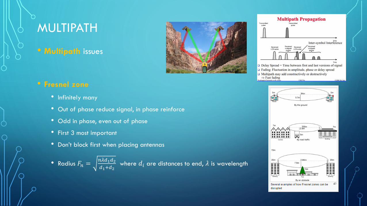
• Multipath issues
• Fresnel zone
• Infinitely many
• Out of phase reduce signal, in phase reinforce
• Odd in phase, even out of phase
• First 3 most important
• Don’t block first when placing antennas
• Radius 𝐹𝑛 =𝑛𝜆𝑑1𝑑2
𝑑1+𝑑2where 𝑑𝑖 are distances to end, 𝜆 is wavelength

CHANNEL CAPACITY
• Channel capacity: tight upper bound on rate at which information can be
transmitted over a communication channel. Symbol is C
• Nyquist rate: upper limit on symbol transfer rate, ≤ 2* bandwidth B
• If symbol is a bit (bi-level encoding), then bit rate ≤ 2𝐵
• Multi-level encoding: bit rate ≤ 2𝐵 log2𝑀
• Shannon-Hartley Theorem:
• Signal to noise S/N
• Capacity 𝐶 = 𝐵 log2 1 + 𝑆/𝑁
CHANNEL CAPACITY
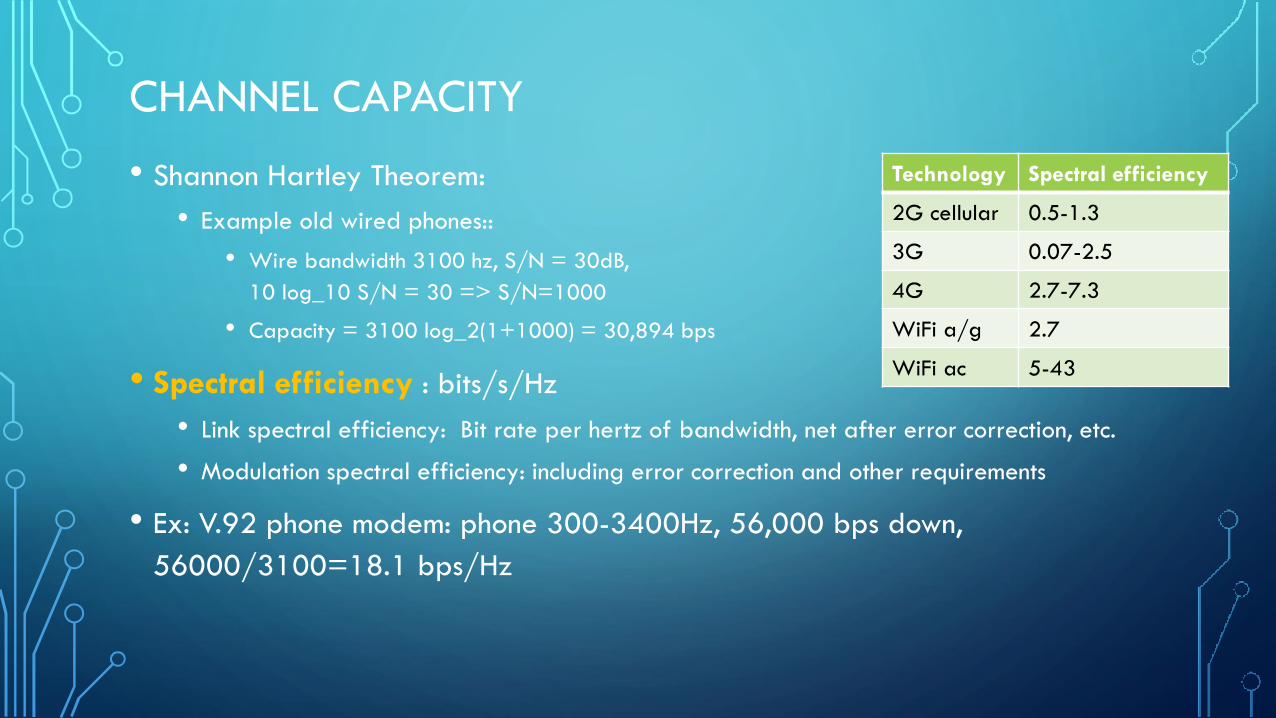
• Shannon Hartley Theorem:
• Example old wired phones::
• Wire bandwidth 3100 hz, S/N = 30dB,
10 log_10 S/N = 30 => S/N=1000
• Capacity = 3100 log_2(1+1000) = 30,894 bps
• Spectral efficiency : bits/s/Hz
• Link spectral efficiency: Bit rate per hertz of bandwidth, net after error correction, etc.
• Modulation spectral efficiency: including error correction and other requirements
• Ex: V.92 phone modem: phone 300-3400Hz, 56,000 bps down,
56000/3100=18.1 bps/Hz
Technology Spectral efficiency
2G cellular 0.5-1.3
3G 0.07-2.5
4G 2.7-7.3
WiFi a/g 2.7
WiFi ac 5-43
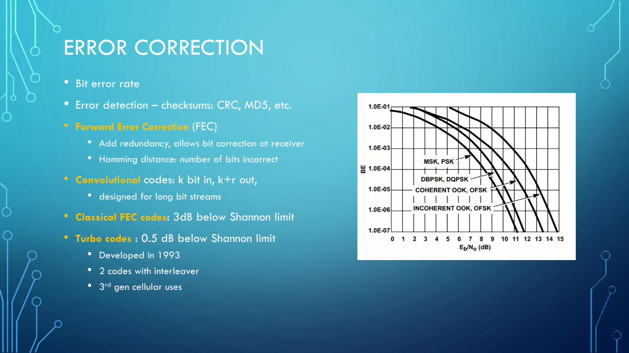
ERROR CORRECTION
• Bit error rate
• Error detection – checksums: CRC, MD5, etc.
• Forward Error Correction (FEC)
• Add redundancy, allows bit correction at receiver
• Hamming distance: number of bits incorrect
• Convolutional codes: k bit in, k+r out,
• designed for long bit streams
• Classical FEC codes: 3dB below Shannon limit
• Turbo codes : 0.5 dB below Shannon limit
• Developed in 1993
• 2 codes with interleaver
• 3rd gen cellular uses
HIGHER LAYERS
• Above physical layer are many more layers
• OSI model is a good reference
• Error correction
• Most advanced designs are packet networks, like IP
• Security

EXAMPLE: FM RADIO (US)
• 88-108 MHz
• Each channel gets 200 kHz bandwidth
• Digital : FM in-band on-channel (IBOC)
• Digital in sidebands of usual FM stations
• Increases interference for many older receivers
• 57kHz subcarrier gives station name, GPS data for commercial receivers, radio text, at
1187.5 bps
• OFDM and proprietary compressed
• Gives 100, 112, 125, or 150 kbits/s data depending on power.
• Can split into multiple channels
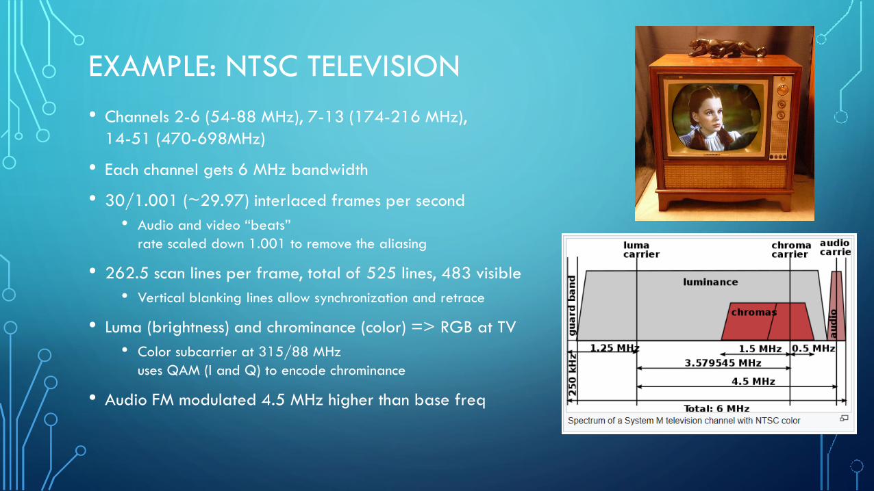
EXAMPLE: NTSC TELEVISION
• Channels 2-6 (54-88 MHz), 7-13 (174-216 MHz),
14-51 (470-698MHz)
• Each channel gets 6 MHz bandwidth
• 30/1.001 (~29.97) interlaced frames per second
• Audio and video “beats”
rate scaled down 1.001 to remove the aliasing
• 262.5 scan lines per frame, total of 525 lines, 483 visible
• Vertical blanking lines allow synchronization and retrace
• Luma (brightness) and chrominance (color) => RGB at TV
• Color subcarrier at 315/88 MHz
uses QAM (I and Q) to encode chrominance
• Audio FM modulated 4.5 MHz higher than base freq
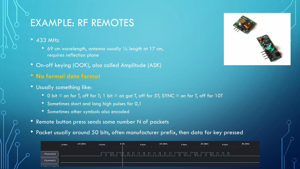
EXAMPLE: RF REMOTES
• 433 MHz
• 69 cm wavelength, antenna usually ¼ length at 17 cm,
requires reflection plane
• On-off keying (OOK), also called Amplitude (ASK)
• No formal data format
• Usually something like:
• 0 bit = on for T, off for T; 1 bit = on got T, off for 5T; SYNC = on for T, off for 10T
• Sometimes short and long high pulses for 0,1
• Sometimes other symbols also encoded
• Remote button press sends some number N of packets
• Packet usually around 50 bits, often manufacturer prefix, then data for key pressed
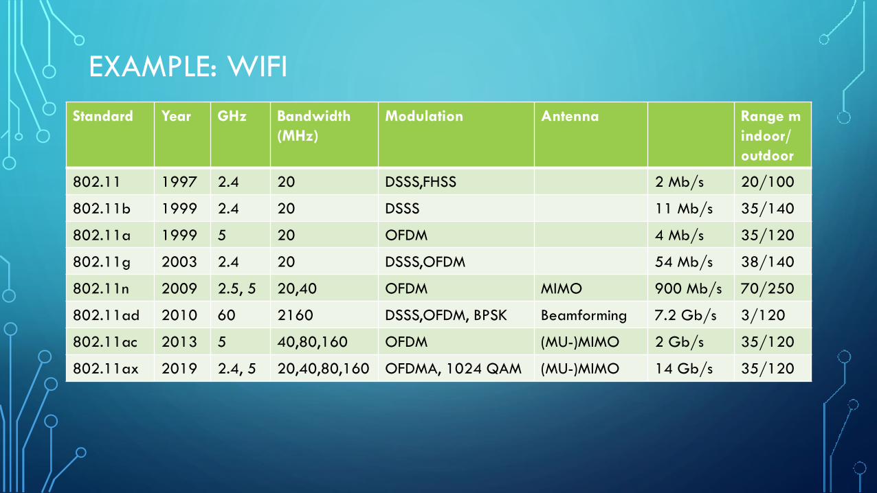
EXAMPLE: WIFI
Standard Year GHz Bandwidth
(MHz)
Modulation Antenna Range m
indoor/
outdoor
802.11 1997 2.4 20 DSSS,FHSS 2 Mb/s 20/100
802.11b 1999 2.4 20 DSSS 11 Mb/s 35/140
802.11a 1999 5 20 OFDM 4 Mb/s 35/120
802.11g 2003 2.4 20 DSSS,OFDM 54 Mb/s 38/140
802.11n 2009 2.5, 5 20,40 OFDM MIMO 900 Mb/s 70/250
802.11ad 2010 60 2160 DSSS,OFDM, BPSK Beamforming 7.2 Gb/s 3/120
802.11ac 2013 5 40,80,160 OFDM (MU-)MIMO 2 Gb/s 35/120
802.11ax 2019 2.4, 5 20,40,80,160 OFDMA, 1024 QAM (MU-)MIMO 14 Gb/s 35/120
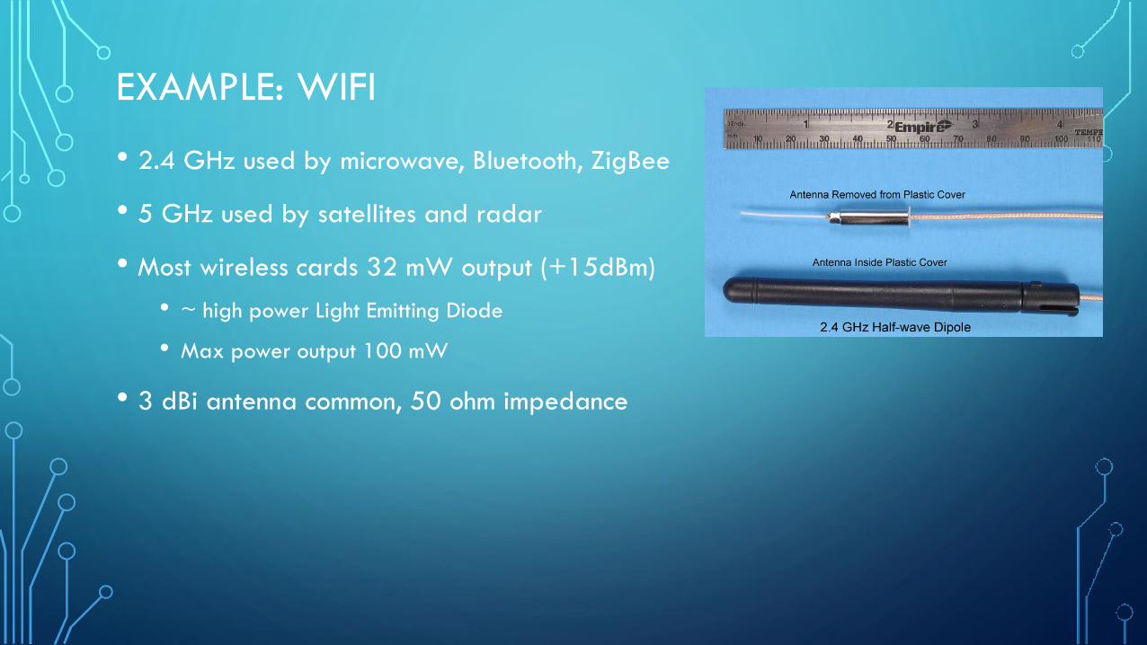
EXAMPLE: WIFI
• 2.4 GHz used by microwave, Bluetooth, ZigBee
• 5 GHz used by satellites and radar
• Most wireless cards 32 mW output (+15dBm)
• ~ high power Light Emitting Diode
• Max power output 100 mW
• 3 dBi antenna common, 50 ohm impedance
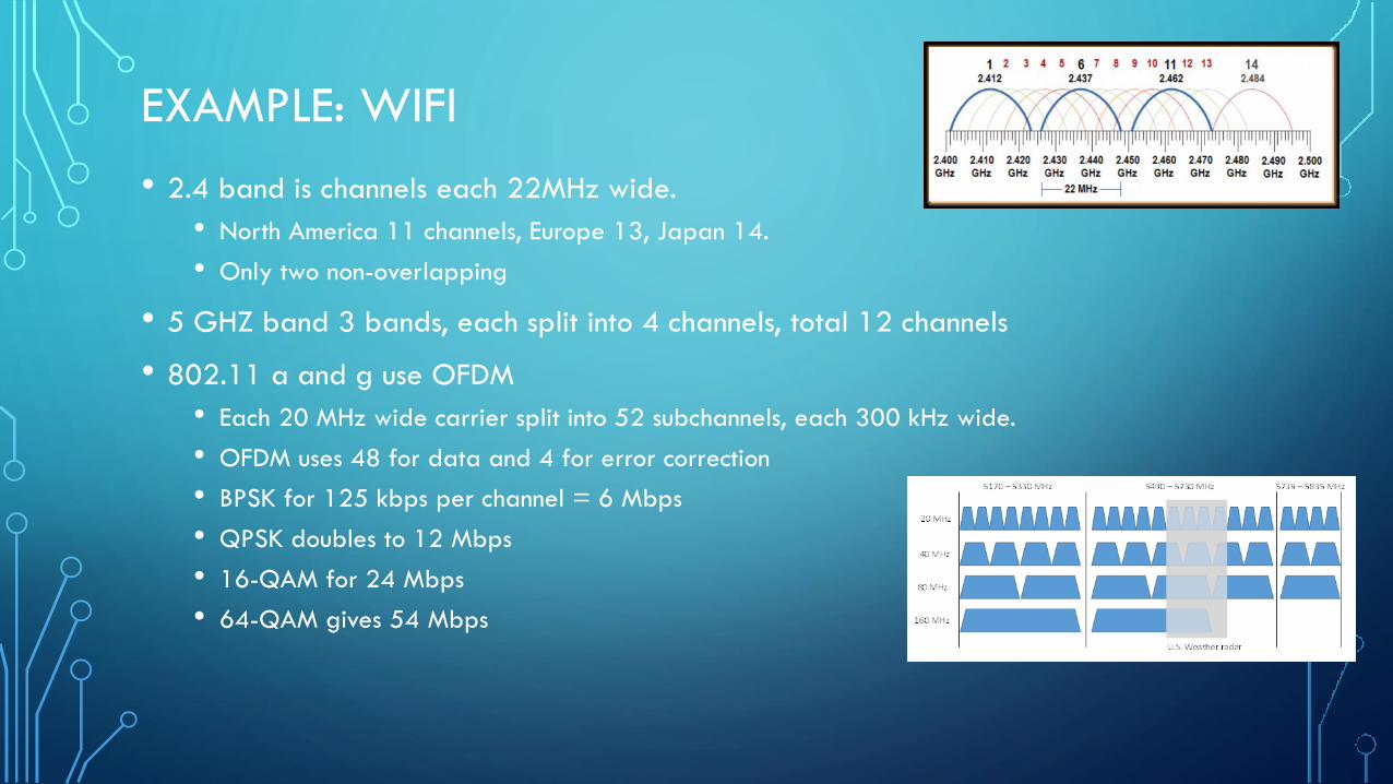
EXAMPLE: WIFI
• 2.4 band is channels each 22MHz wide.
• North America 11 channels, Europe 13, Japan 14.
• Only two non-overlapping
• 5 GHZ band 3 bands, each split into 4 channels, total 12 channels
• 802.11 a and g use OFDM
• Each 20 MHz wide carrier split into 52 subchannels, each 300 kHz wide.
• OFDM uses 48 for data and 4 for error correction
• BPSK for 125 kbps per channel = 6 Mbps
• QPSK doubles to 12 Mbps
• 16-QAM for 24 Mbps
• 64-QAM gives 54 Mbps

EXAMPLE: WIFI
• 802.11b uses Direct Sequence Spread Spectrum (DSSS)
• BPSK at 1 Mbps, QPSK for 2 Mbps, Complementary Code Keying
(CCK) for 5.5 and 11 Mbps
• 11 bit Barker code 1-2 Mbps
• unaligned auto correlations are -1 and 0, aligned is +11
• complementary code keying 5.5-11 Mbps
• 802.11n
• Channel bonding aggregates two 20 MHz channels into one 40 MHz channel
• MIMO (Multiple input/output) – uses multipath signals to the advantage of the receiver
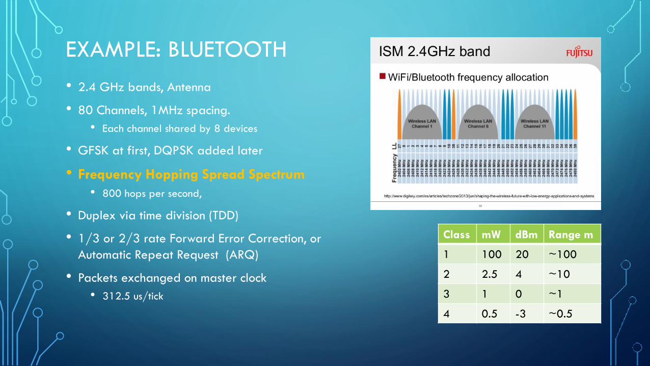
EXAMPLE: BLUETOOTH
• 2.4 GHz bands, Antenna
• 80 Channels, 1MHz spacing.
• Each channel shared by 8 devices
• GFSK at first, DQPSK added later
• Frequency Hopping Spread Spectrum
• 800 hops per second,
• Duplex via time division (TDD)
• 1/3 or 2/3 rate Forward Error Correction, or
Automatic Repeat Request (ARQ)
• Packets exchanged on master clock
• 312.5 us/tick
Class mW dBm Range m
1 100 20 ~100
2 2.5 4 ~10
3 1 0 ~1
4 0.5 -3 ~0.5

EXAMPLE: ZIGBEE
• 10-20 m
• 250 kbit/s
• 2.4 GHz (+ other in some countries)
• 16 channels, 5 MHz apart, 2MHz bandwidth
• Direct Sequence Spread Spectrum coding
• BPSK in 868 and 915 MHz bands
• OQPSK (2 bits per symbol) in 2.4 GHz band
• ¼ length antenna is 3.125 cm long
• 0-20 dbm (1-100 mW) transmit
• Duty cycle for power savings
• 128 bit key for security

EXAMPLE: SATELLITE RADIO
• Sirius XM uses 2.3200-2.3325 GHz
• Three 4MHz carriers, all decoded
• XM radio uses 2.3325-2.3450 GHz
• Six 2MHz carriers, three decode by receiver
• User level antennas ~40dB gain
• OFDM QPSK signals
• Each two-carrier group broadcasts ~100
8-kilobit-per-second streams in approximately
4 MHz of radio spectrum
• Audio compressed by proprietary methods

EXAMPLE: GPS
• 1.57542 GHz (L1 signal), 1.2276 GHz (L2 signal)
• L3 at 1.38105 GHz used to report detected nuclear explosions to US
• L4 at 1.379913 GHz is for studying ionosphere
• L5 at 1.17645 is part of GPS modernization
• 24+ satellites, 20,000 km altitude, 4-12 visible at a time
• 25.6 W transmitter, antenna gain 13 dBi gives 27 dbW
• free space loss 182 dBW, leaves -155 dBW
• Each has atomic clock with 1 nanosecond tick rate
• Want 20-30 ns accuracy on clock ticks at earth
• GPS signals are Right Hand Circularly Polarized
• Less vulnerable to destructive interference due to reflections
• Difficult to read in small devices, which are usually vertically polarized

EXAMPLE: GPS
• Sends code known to receiver, alignment determines epoch
• Sends Time of Transmission
• Receiver measures 4 satellites, and from difference in times, computes receiver location
• Modern receivers can track 12-20 satellites at once for more accuracy
• Transmits on L1 an L2 freqs, 50 bps, each message takes 750 seconds to complete
(12.5 minutes)
• Relativity – Special and General both apply
• Special relativity: Orbital speed 14,000 km/hr. Ground sees satellite clock as slower, adds
about 7 ms per day.
• General relativity: Earth mass curves space, satellites tick faster than ground by 45 ms per
day.
• Net is 45-7=38 ms per day needs added at ground, else off by 10km/day
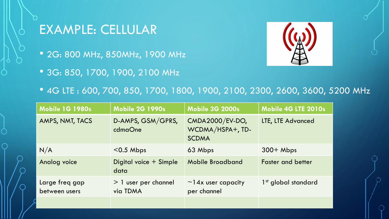
EXAMPLE: CELLULAR
Mobile 1G 1980s Mobile 2G 1990s Mobile 3G 2000s Mobile 4G LTE 2010s
AMPS, NMT, TACS D-AMPS, GSM/GPRS,
cdmaOne
CMDA2000/EV-DO,
WCDMA/HSPA+, TD-
SCDMA
LTE, LTE Advanced
N/A <0.5 Mbps 63 Mbps 300+ Mbps
Analog voice Digital voice + Simple
data
Mobile Broadband Faster and better
Large freq gap
between users
> 1 user per channel
via TDMA
~14x user capacity
per channel
1st global standard
• 2G: 800 MHz, 850MHz, 1900 MHz
• 3G: 850, 1700, 1900, 2100 MHz
• 4G LTE : 600, 700, 850, 1700, 1800, 1900, 2100, 2300, 2600, 3600, 5200 MHz
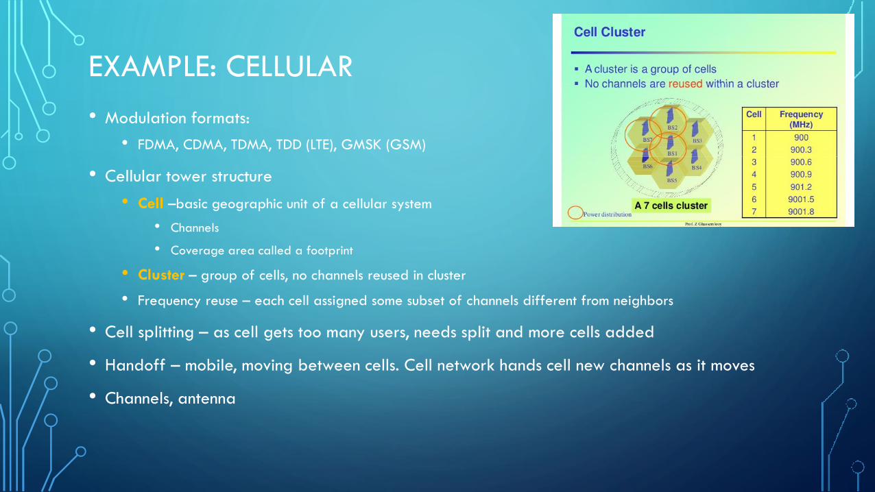
EXAMPLE: CELLULAR
• Modulation formats:
• FDMA, CDMA, TDMA, TDD (LTE), GMSK (GSM)
• Cellular tower structure
• Cell –basic geographic unit of a cellular system
• Channels
• Coverage area called a footprint
• Cluster – group of cells, no channels reused in cluster
• Frequency reuse – each cell assigned some subset of channels different from neighbors
• Cell splitting – as cell gets too many users, needs split and more cells added
• Handoff – mobile, moving between cells. Cell network hands cell new channels as it moves
• Channels, antenna

EXAMPLE: CELLULAR
• Components:
• Public Switched Telephone Network (PSTN)
• Global backbone, wiring, local networks long-haul networks
• Mobile Telephone Switching Office (MTSO)
• Controls calls, tracks billing, locates subscribers
• Cell site and antenna
• Mobile Subscriber Unit (MSU). 3 types:
• Mobile telephone (trunk of car style): typical transmit power 4.0 watts
• Portable (hand held): 0.6 watts
• Transportable: (1.6 watts)

EXAMPLE: CELLULAR 3G
• 1998
• 384 kbs – 21.6 Mbps (“3.5G”)
• Evolving encoding: UMTS, CMDA2000 and revisions…
• CMDA2000 Rev C
• QPSK, 8-PSK, 16-QAM
• SNR required -12 to 9.7 (slow to fast)

EXAMPLE: CELLULAR 4G
• 2009
• MIMO, MU-MIMO
• OFDM, OFDMA, Single Carrier FDMA (SC-FMDA)
• Turbo codes for error correction
• Adaptive modulation and error correction
• All IP packet switched network
• 100 Mbps high mobility, 1 Gbps low mobility
• Link spectral efficiency 15 bit/s/Hz downlink, 6.75 uplink
• LTE peak download 1Gbps, upload 500 Mbps

EXAMPLE: CELLULAR 5G
• First wave ~2021, trials 2018-2019
• 9 GHz of unlicensed spectrum at 60 GHz (current cellular has ~800 MHz of
spectrum). Some current testing at 15 GHz
• Want
• 10-100x data rate,
• 1000x network capacity (10^6 devices / km^2) using smaller cells
• 10x energy efficiency,
• 10-20x lower latency (1ms)
• 20 Gbps throughput
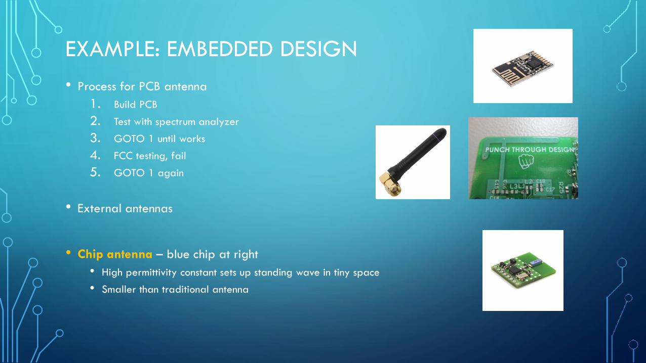
EXAMPLE: EMBEDDED DESIGN
• Process for PCB antenna
1. Build PCB
2. Test with spectrum analyzer
3. GOTO 1 until works
4. FCC testing, fail
5. GOTO 1 again
• External antennas
• Chip antenna – blue chip at right
• High permittivity constant sets up standing wave in tiny space
• Smaller than traditional antenna
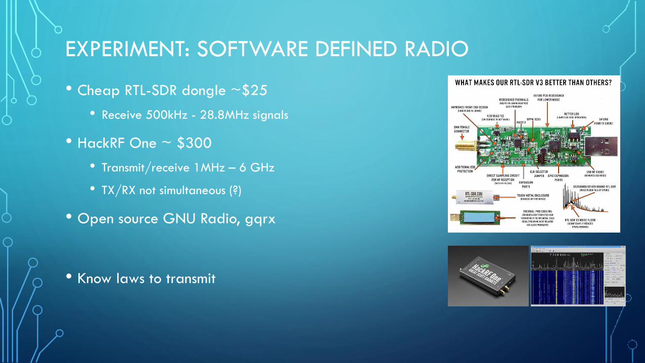
EXPERIMENT: SOFTWARE DEFINED RADIO
• Cheap RTL-SDR dongle ~$25
• Receive 500kHz - 28.8MHz signals
• HackRF One ~ $300
• Transmit/receive 1MHz – 6 GHz
• TX/RX not simultaneous (?)
• Open source GNU Radio, gqrx
• Know laws to transmit
SECURITY ISSUES
• Protocol holes
• Snooping
• Leaks
• Blocking
• Physical layer (def of hardware, encoding and signaling, transmission and
reception, topology)
• Breaks galore!
QUESTIONS ?
THE END