Embed Size (px)
Citation preview
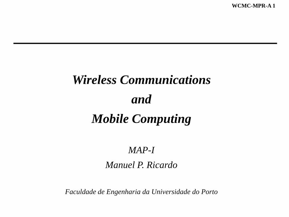
WCMC-MPR-A 1
Wireless Communications
and
Mobile Computing
MAP-I
Manuel P. Ricardo
Faculdade de Engenharia da Universidade do Porto
WCMC-MPR-A 2
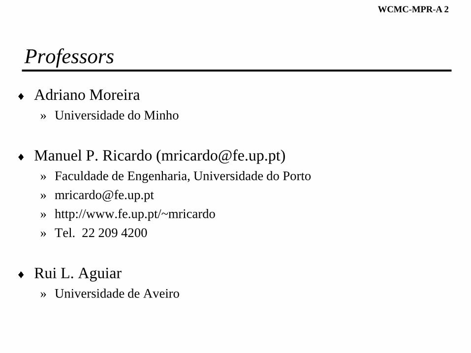
Professors
Adriano Moreira
» Universidade do Minho
Manuel P. Ricardo ([email protected])
» Faculdade de Engenharia, Universidade do Porto
» http://www.fe.up.pt/~mricardo
» Tel. 22 209 4200
Rui L. Aguiar
» Universidade de Aveiro
WCMC-MPR-A 3
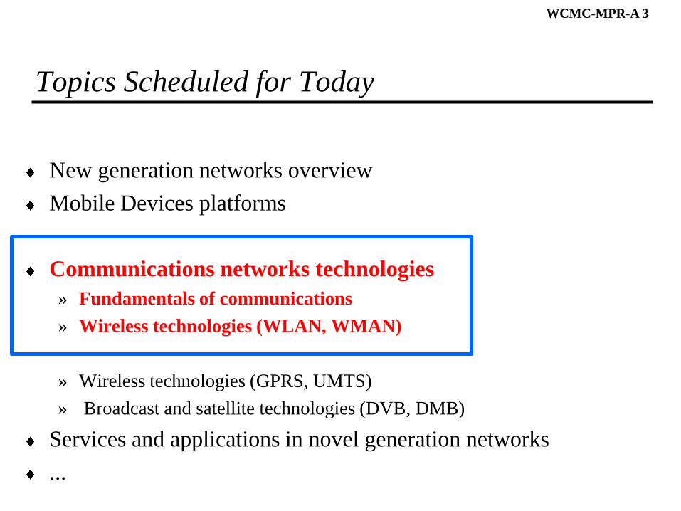
Topics Scheduled for Today
New generation networks overview
Mobile Devices platforms
Communications networks technologies
» Fundamentals of communications
» Wireless technologies (WLAN, WMAN)
» Wireless technologies (GPRS, UMTS)
» Broadcast and satellite technologies (DVB, DMB)
Services and applications in novel generation networks
...
3
WCMC-MPR-A 4
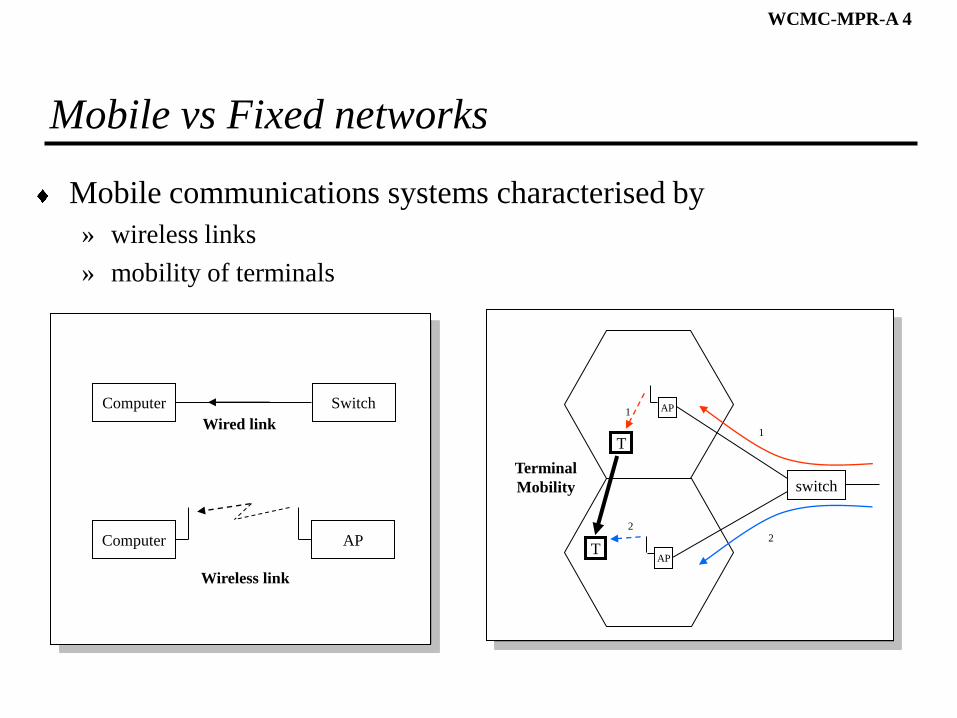
Mobile vs Fixed networks
Mobile communications systems characterised by
» wireless links
» mobility of terminals
T
switch
AP
TAP
1
2
1
2
Terminal
Mobility
Computer Switch
Computer AP
Wireless link
Wired link
WCMC-MPR-A 5
To Think About
How to obtain a low Bit Error Ratio (BER) in a wireless link?
WCMC-MPR-A 6
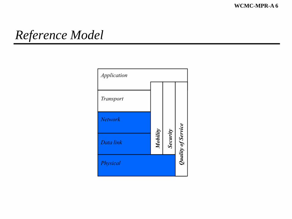
Reference Model
Physical
Network
Transport
Data link
Application
Mo
bil
ity
Sec
uri
ty
Qu
ali
ty o
f S
ervi
ce

WCMC-MPR-A 7
Wireless Transmission
WCMC-MPR-A 8
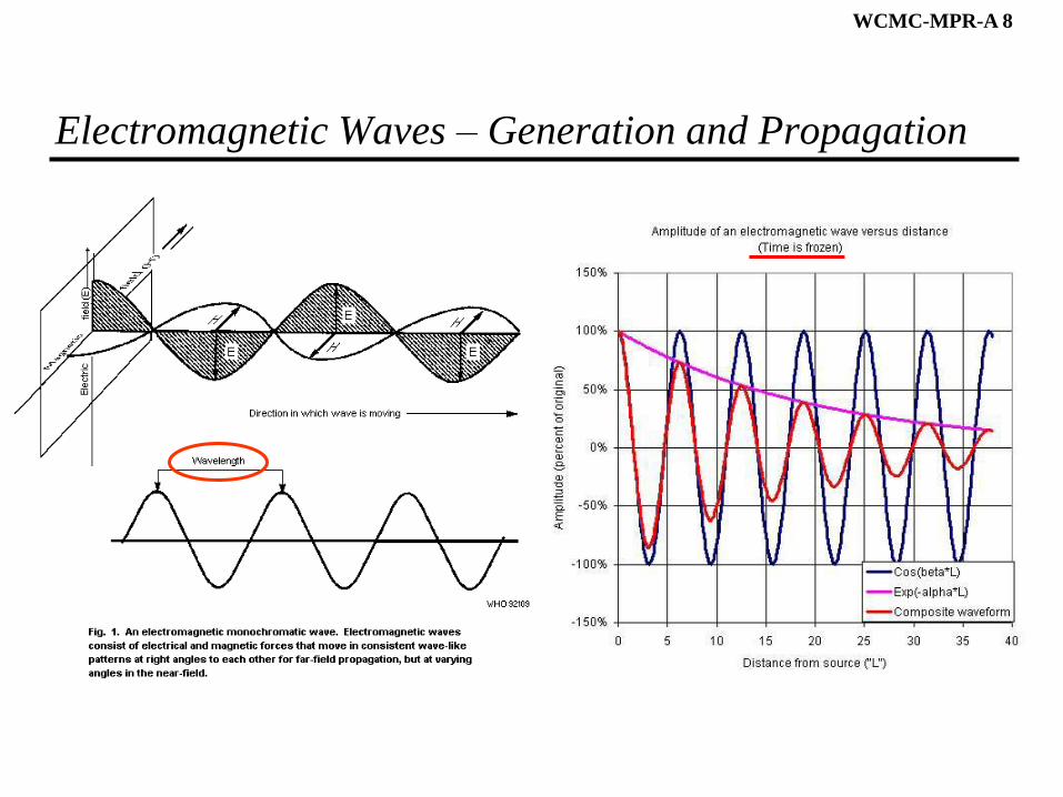
Electromagnetic Waves – Generation and Propagation
WCMC-MPR-A 9
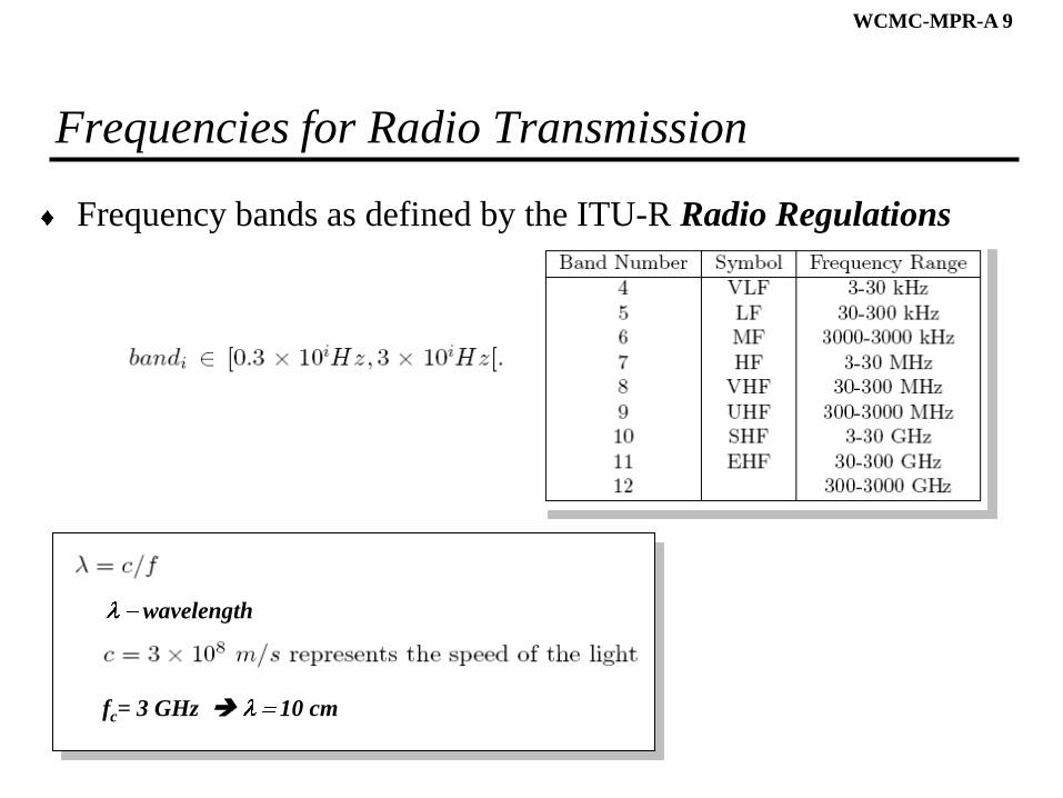
Frequencies for Radio Transmission
Frequency bands as defined by the ITU-R Radio Regulations
fc= 3 GHz 10 cm
wavelength
WCMC-MPR-A 10
To Think About
How does the power of a received signal depend on the
» distance?
» wavelength ( )?
WCMC-MPR-A 11
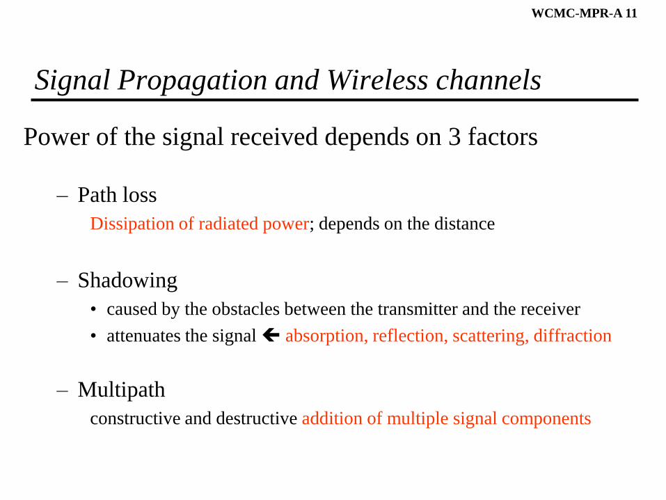
Signal Propagation and Wireless channels
Power of the signal received depends on 3 factors
– Path loss
Dissipation of radiated power; depends on the distance
– Shadowing
• caused by the obstacles between the transmitter and the receiver
• attenuates the signal absorption, reflection, scattering, diffraction
– Multipath
constructive and destructive addition of multiple signal components
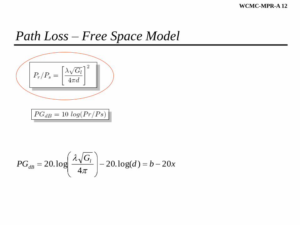
WCMC-MPR-A 12
Path Loss – Free Space Model
xbdG
PG l
dB 20)log(.204
log.20
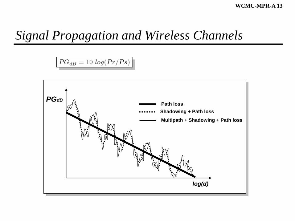
WCMC-MPR-A 13
Signal Propagation and Wireless Channels
PGdB
log(d)
Path loss
Shadowing + Path loss
Multipath + Shadowing + Path loss
WCMC-MPR-A 14
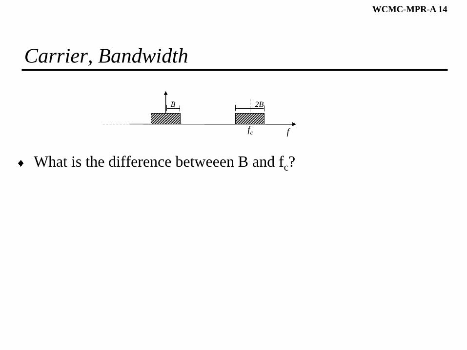
Carrier, Bandwidth
What is the difference betweeen B and fc?
ffc
B 2B
WCMC-MPR-A 15
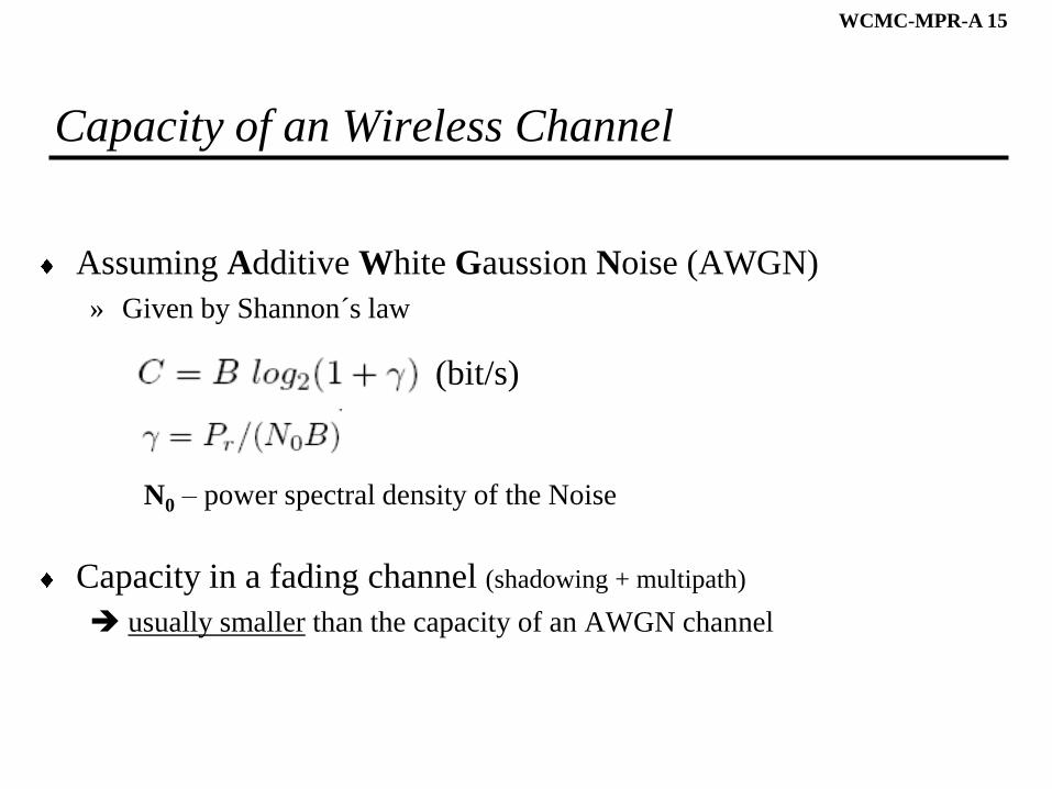
Capacity of an Wireless Channel
Assuming Additive White Gaussion Noise (AWGN)
» Given by Shannon´s law
N0 – power spectral density of the Noise
Capacity in a fading channel (shadowing + multipath)
usually smaller than the capacity of an AWGN channel
(bit/s)
WCMC-MPR-A 16
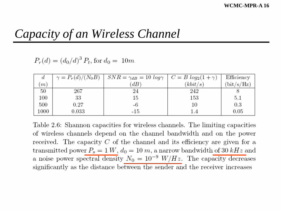
Capacity of an Wireless Channel
WCMC-MPR-A 17
To Think About
How can we transmit bits using a continuous carrier?
WCMC-MPR-A 18
Digital Modulation
Digital modulation
» maps information bits into an analogue signal (carrier)
Receiver
» determines the original bit sequence based on the signal received
Two categories of digital modulation
» amplitude/phase modulation
» frequency modulation
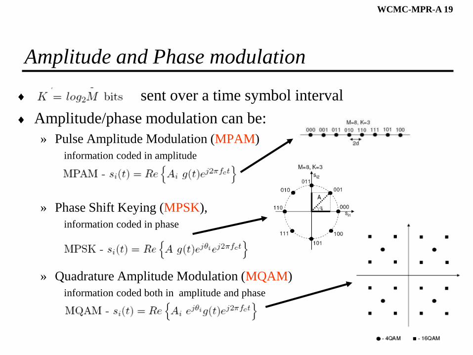
WCMC-MPR-A 19
Amplitude and Phase modulation
sent over a time symbol interval
Amplitude/phase modulation can be:
» Pulse Amplitude Modulation (MPAM)
information coded in amplitude
» Phase Shift Keying (MPSK),
information coded in phase
» Quadrature Amplitude Modulation (MQAM)
information coded both in amplitude and phase
WCMC-MPR-A 20
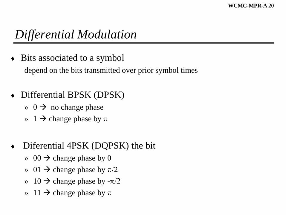
Differential Modulation
Bits associated to a symbol
depend on the bits transmitted over prior symbol times
Differential BPSK (DPSK)
» 0 no change phase
» 1 change phase by
Diferential 4PSK (DQPSK) the bit
» 00 change phase by 0
» 01 change phase by
» 10 change phase by -
» 11 change phase by
WCMC-MPR-A 21
Coding for Wireless Channels
Coding enables bit errors to be either
detected or corrected by receiver
Codes designed for AWGN channels
» do not work well on fading channels
» cannot correct the long error bursts that occur in fading
Codes for fading channels are usually
» based on an AWGN channel code
» combined with interleaving
» objective spread error bursts over multiple codewords
WCMC-MPR-A 22
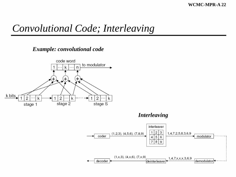
Convolutional Code; Interleaving
Example: convolutional code
Interleaving
WCMC-MPR-A 23
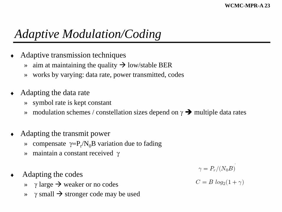
Adaptive Modulation/Coding
Adaptive transmission techniques
» aim at maintaining the quality low/stable BER
» works by varying: data rate, power transmitted, codes
Adapting the data rate
» symbol rate is kept constant
» modulation schemes / constellation sizes depend on multiple data rates
Adapting the transmit power
» compensate Pr/N0B variation due to fading
» maintain a constant received
Adapting the codes
» large weaker or no codes
» small stronger code may be used
WCMC-MPR-A 24
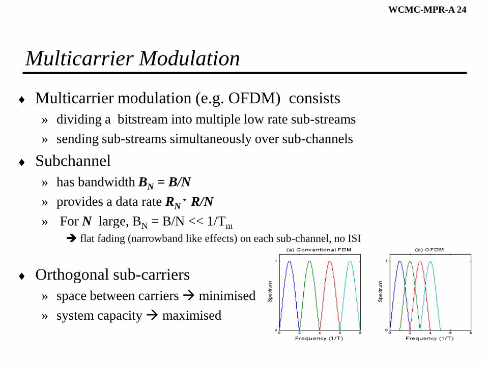
Multicarrier Modulation
Multicarrier modulation (e.g. OFDM) consists
» dividing a bitstream into multiple low rate sub-streams
» sending sub-streams simultaneously over sub-channels
Subchannel
» has bandwidth BN = B/N
» provides a data rate RN R/N
» For N large, BN = B/N << 1/Tm
flat fading (narrowband like effects) on each sub-channel, no ISI
Orthogonal sub-carriers
» space between carriers minimised
» system capacity maximised
WCMC-MPR-A 25
Wireless Data Link
and
Medium Access Control
WCMC-MPR-A 26
How to transmit signals in both directions simultaneously?
How to enable multiple users to communicate simultaneously?
WCMC-MPR-A 27
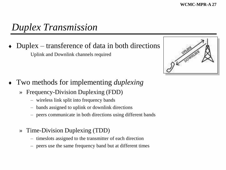
Duplex Transmission
Duplex – transference of data in both directionsUplink and Downlink channels required
Two methods for implementing duplexing
» Frequency-Division Duplexing (FDD)
– wireless link split into frequency bands
– bands assigned to uplink or downlink directions
– peers communicate in both directions using different bands
» Time-Division Duplexing (TDD)
– timeslots assigned to the transmitter of each direction
– peers use the same frequency band but at different times
WCMC-MPR-A 28
To Think About
How to place several sender-receiver pairs communicating in the
same physical space?
WCMC-MPR-A 29
Multi-Access Schemes
Multi-access schemes
» Identify radio resources
» Assign resources to multiple users/terminals
Multi-access schemes
» Frequency-Division Multiple Access (FDMA)
resources divided in portions of spectrum (channels)
» Time-Division Multiple Access (TDMA)
resources divided in time slots
» Code-Division Multiple Access (CDMA)
resources divided in codes
WCMC-MPR-A 30
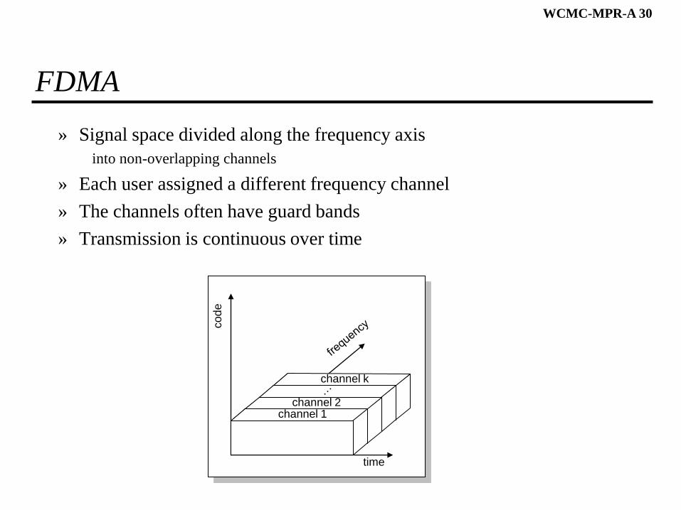
FDMA
» Signal space divided along the frequency axis
into non-overlapping channels
» Each user assigned a different frequency channel
» The channels often have guard bands
» Transmission is continuous over time
channel k
channel 2
time
co
de
channel 1
WCMC-MPR-A 31
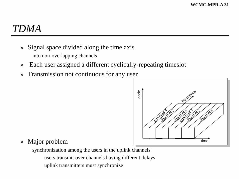
TDMA
» Signal space divided along the time axis
into non-overlapping channels
» Each user assigned a different cyclically-repeating timeslot
» Transmission not continuous for any user
» Major problem
synchronization among the users in the uplink channels
users transmit over channels having different delays
uplink transmitters must synchronize
timeco
de
… …
WCMC-MPR-A 32
CDMA
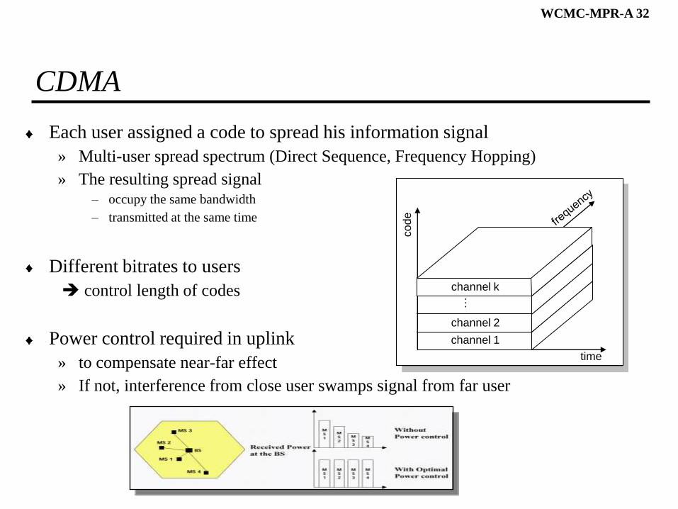
Each user assigned a code to spread his information signal
» Multi-user spread spectrum (Direct Sequence, Frequency Hopping)
» The resulting spread signal– occupy the same bandwidth
– transmitted at the same time
Different bitrates to users
control length of codes
Power control required in uplink
» to compensate near-far effect
» If not, interference from close user swamps signal from far user
time
co
de
channel 1
channel 2
channel k
…
WCMC-MPR-A 33
Combined Multi-access Techniques
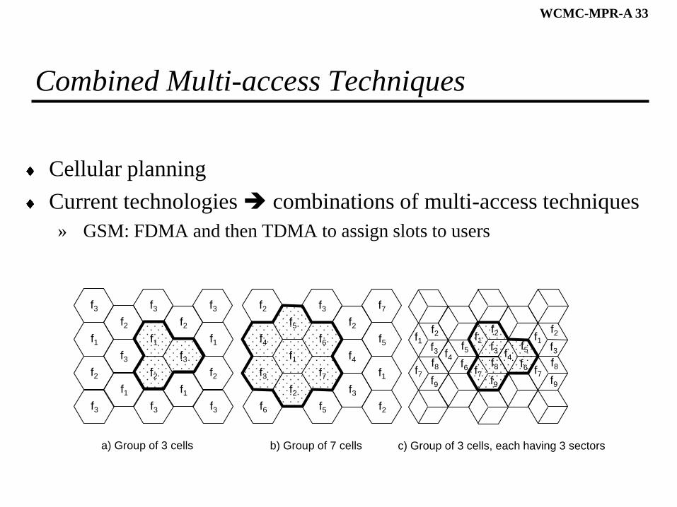
Cellular planning
Current technologies combinations of multi-access techniques
» GSM: FDMA and then TDMA to assign slots to users
f1
f3
f3
f2
f2
f1
f3
f1
f3
f3
f2
f2
f1
f3
f1
f3
f3
f2
a) Group of 3 cells
f4
f2
f6
f3
f5
f2
f1
f6
f3
f5
f7
f2
f3
f4
f5
f7
f2
f1
b) Group of 7 cells c) Group of 3 cells, each having 3 sectors
f2
f3f1
f2
f3f1
f2
f3f1
f5
f6f4
f5
f6f4
f8
f9f7
f8
f9f7
f8
f9f7
WCMC-MPR-A 34
Wireless Medium Access Control Issues
Medium Access Control (MAC)
» Assign radio resources to terminals along the time
3 type of resource allocation methods
» dedicated assignment
resources assigned in a predetermined, fixed, mode
» random access
terminals contend for the channel
» demand-based
terminals ask for reservations
using dedicated/random access channels
WCMC-MPR-A 35
Alhoa, S-Alhoa, CSMA
Alhoa Efficiency of 18 %if station has a packet to transmit
transmits the packet
waits confirmation from receiver (ACK)
if confirmation does not arrive in round trip time, the station
computes random backofftime retransmits packet
Slotted Alhoa Efficiency of 37 %stations transmit just at the beginning of each time slot
Carrier Sense Multiple Access (CSMA) Efficiency of 54 %– station listens the carrier before it sends the packet
– If medium busy station defers its transmission
ACK required for Alhoa, S-Alhoa and CSMA
WCMC-MPR-A 36
CSMA/CD – Not Used in Wireless
CDMA/Collision Detection Efficiency < 80%– station monitors de medium (carrier sense)
medium free transmits the packet
medium busy waits until medium is free transmits packet
if, during a round trip time, detects a collision
station aborts transmission and stresses collision
(no ACK packet)
Problems of CDMA/CD in wireless networksCarrier sensing
carrier sensing difficult for hidden terminal
Collision detection
near-end interference makes simultaneous transmission and reception difficult
WCMC-MPR-A 37
To think about?
How to minimize collision in a wireless medium?
WCMC-MPR-A 38
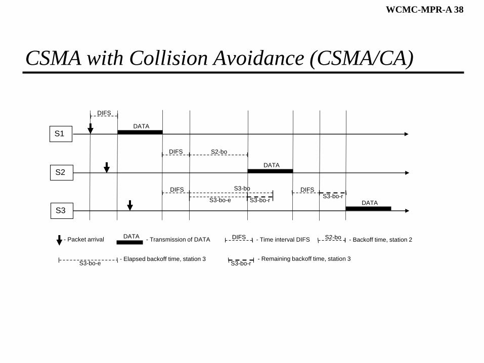
CSMA with Collision Avoidance (CSMA/CA)
S2
DIFS
S3
S1DATA
DIFS S2-bo
DIFS S3-bo
S3-bo-e S3-bo-r
DATA
DIFSS3-bo-r
DATA
- Packet arrivalDATA
- Transmission of DATA DIFS - Time interval DIFS S2-bo - Backoff time, station 2
- Elapsed backoff time, station 3S3-bo-e S3-bo-r
- Remaining backoff time, station 3
WCMC-MPR-A 39
CSMA with Collision Avoidance (CSMA/CA)
Station with a packet to transmit monitors the channel activity until an idle period equal to a Distributed Inter-Frame Space (DIFS) has been observed
If the medium is sensed busy a random backoff interval is selected. The backoff time counter is decremented as long as the channel is sensed idle, stopped when a transmission is detected on the channel, and reactivated when the channel is sensed idle again for more than a DIFS. The station transmits when the backoff time reaches 0
To avoid channel capture, a station must wait a random backoff time between two consecutive packet transmissions, even if the medium is sensed idle in the DIFS time
WCMC-MPR-A 40
CSMA/CA – ACK Required
AP
DIFS
S2
S1
SIFS
DATA
ACK
DIFS S2-Backoff
SIFS
DATA
ACK
- Packet arrivalDATA
- Transmission of DATA DIFS - Time interval DIFS
WCMC-MPR-A 41
CSMA/CA – ACK Required
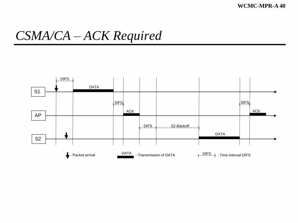
CSMA/CA does not rely on the capability of the stations to detect a collision by hearing their own transmission
A positive acknowledgement is transmitted by the destination station to signal the successful packet transmission
In order to allow an immediate response, the acknowledgement is transmitted following the received packet, after a Short Inter-Frame Space (SIFS)
If the transmitting station does not receive the acknowledge within a specified ACK timeout, or it detects the transmission of a different packet on the channel, it reschedules the packet transmission according to the previous backoff rules.
Efficiency of CSMA/CA depends strongly of the number of competing stations. An efficiency of 60% is commonly found
WCMC-MPR-A 42
To Think About
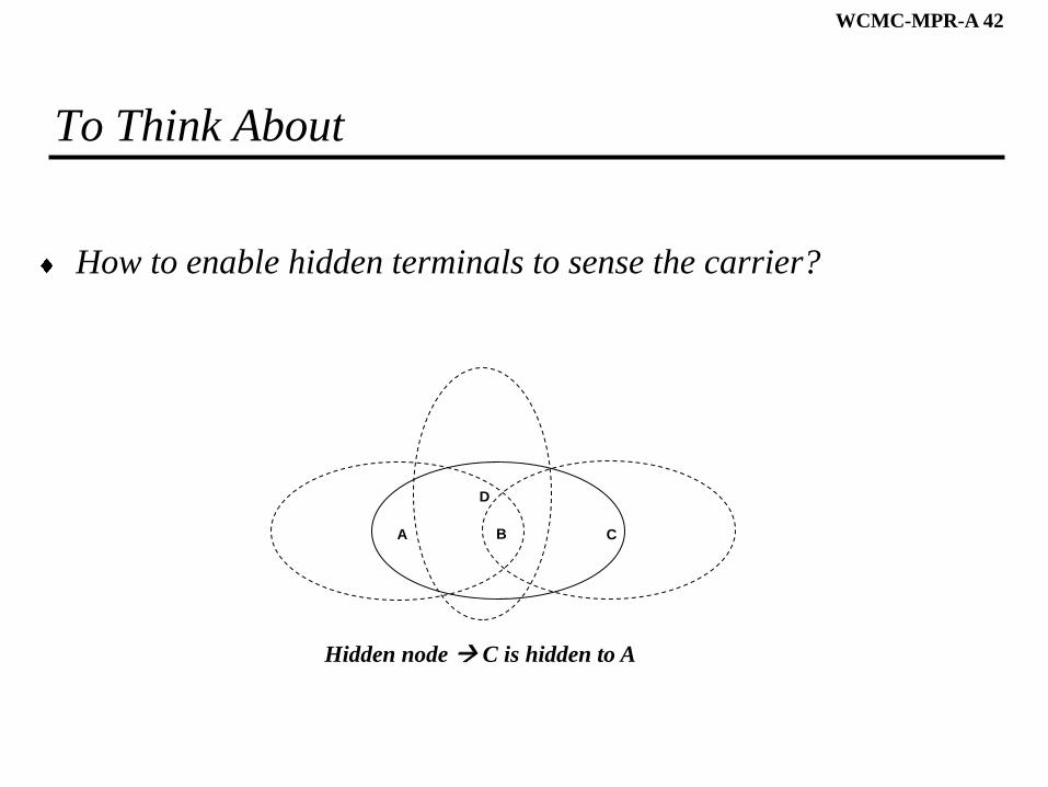
How to enable hidden terminals to sense the carrier?
Hidden node C is hidden to A
A CB
D
WCMC-MPR-A 43
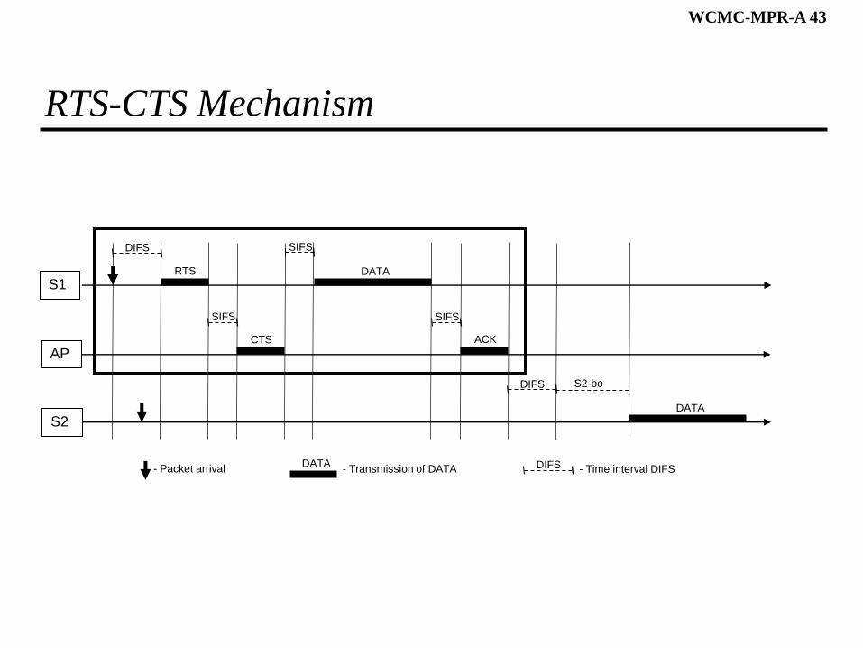
RTS-CTS Mechanism
AP
DIFS
S2
S1
SIFS
DATARTS
DIFS S2-bo
DATA
- Packet arrivalDATA
- Transmission of DATA DIFS - Time interval DIFS
CTS
SIFS
SIFS
ACK
WCMC-MPR-A 44
RTS-CTS Mechanism
For some scenarios where long packets are used or the probability of hidden terminals is not irrelevant, the efficiency of CSMA/CA can be further improved with a Request To Send (RTS) - Clear to Send (CTS) mechanism
The basic concept is that a sender station sends a short RTS message to the receiver station. When the receiver gets a RTS from the sender, it polls the sender by sending a short CTS message. The sender then sends its packet to the receiver. After correctly receiving the packet, the receiver sends a positive acknowledgement (ACK) to the sender
This mechanism is particularly useful to transmit large packets. The listening of the RTS or the CTS messages enable the stations in range respectively of the sender or receiver that a big packet is about to be transmitted. Usually both the RTS and the CTS contain information about the number of slots required to transmit the 4 packets. Using this information the other stations refrain themselves to transmit packets, thus avoiding collisions and increasing the system efficiency.
SIFS are used before the transmission of CTS, Data, and ACK
In optimum conditions the RTS-CTS mechanism may add an efficiency gain of about 15%
WCMC-MPR-A 45
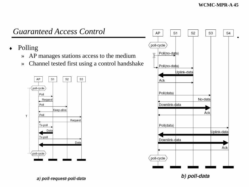
Guaranteed Access Control
Polling
» AP manages stations access to the medium
» Channel tested first using a control handshake
WCMC-MPR-A 46
Fundamental Networking
WCMC-MPR-A 47
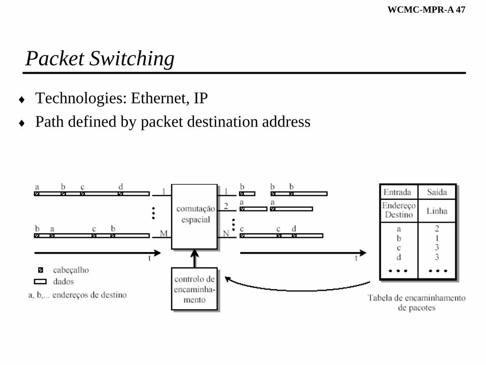
Packet Switching
Technologies: Ethernet, IP
Path defined by packet destination address
WCMC-MPR-A 48
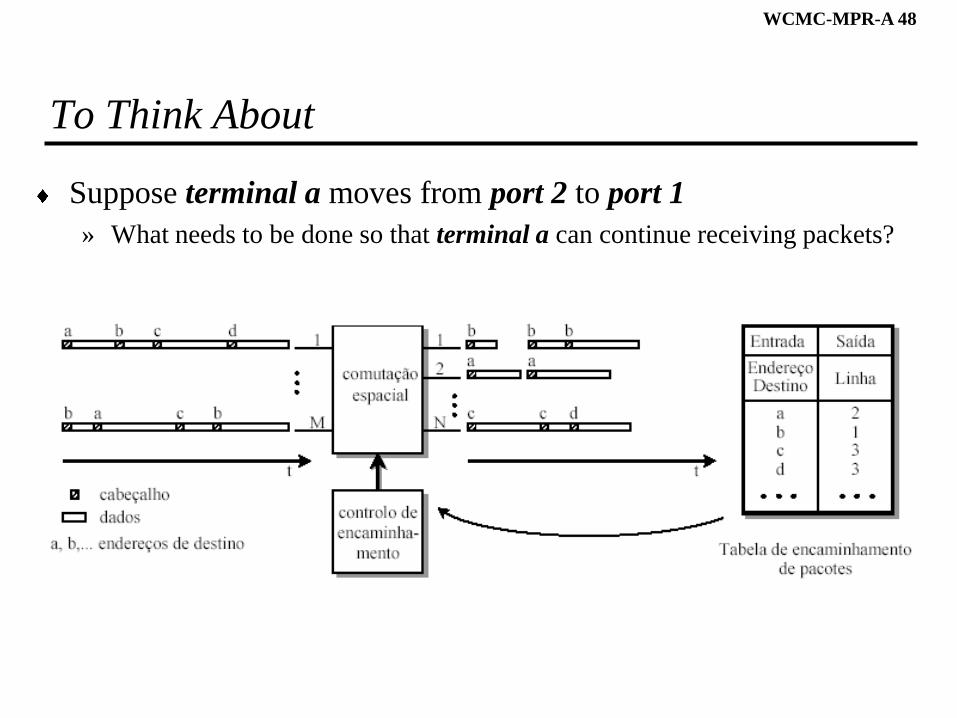
To Think About
Suppose terminal a moves from port 2 to port 1
» What needs to be done so that terminal a can continue receiving packets?
WCMC-MPR-A 49
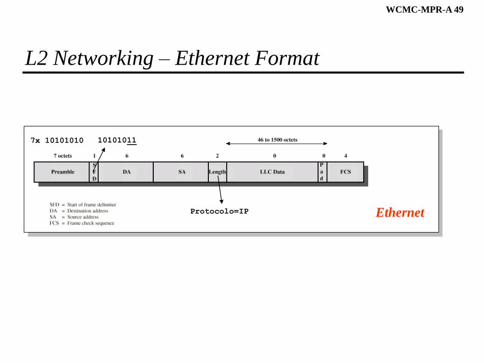
L2 Networking – Ethernet Format
Ethernet
7x 10101010 10101011
Protocolo=IP
WCMC-MPR-A 50
L2 Networking - Bridges
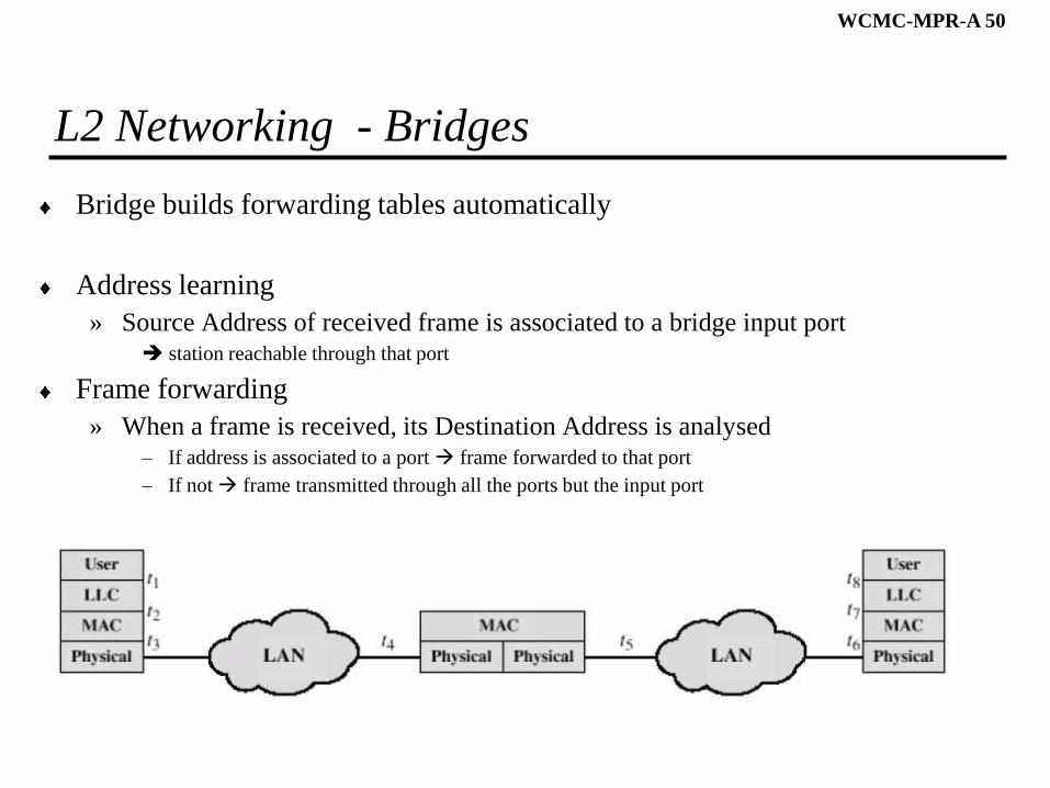
Bridge builds forwarding tables automatically
Address learning
» Source Address of received frame is associated to a bridge input port station reachable through that port
Frame forwarding
» When a frame is received, its Destination Address is analysed– If address is associated to a port frame forwarded to that port
– If not frame transmitted through all the ports but the input port
WCMC-MPR-A 51
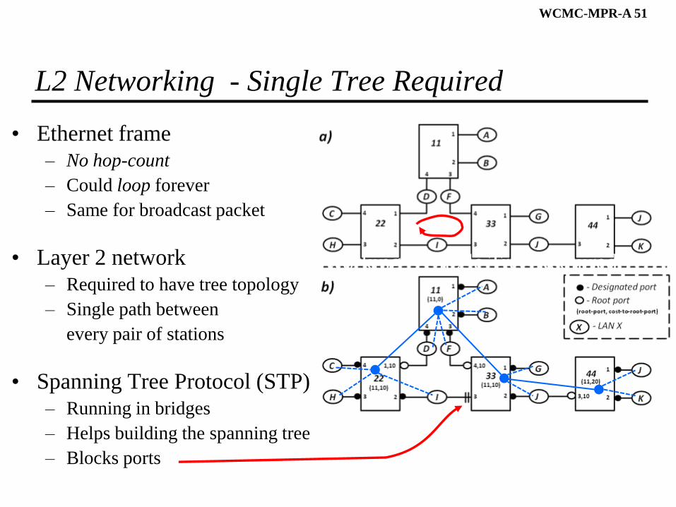
L2 Networking - Single Tree Required
• Ethernet frame
– No hop-count
– Could loop forever
– Same for broadcast packet
• Layer 2 network
– Required to have tree topology
– Single path between
every pair of stations
• Spanning Tree Protocol (STP)
– Running in bridges
– Helps building the spanning tree
– Blocks ports
L2 Networking - Single Tree Required
WCMC-MPR-A 52
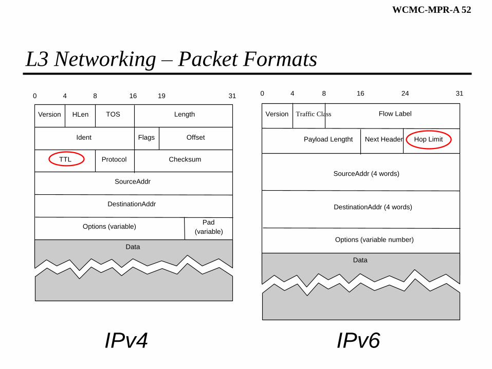
L3 Networking – Packet Formats
IPv4 IPv6
Version HLen TOS Length
Ident Flags Offset
TTL Protocol Checksum
SourceAddr
DestinationAddr
Options (variable)Pad
(variable)
0 4 8 16 19 31
Data
Version Traffic Class Flow Label
Payload Lengtht Next Header Hop Limit
SourceAddr (4 words)
DestinationAddr (4 words)
Options (variable number)
0 4 8 16 24 31
Data
WCMC-MPR-A 53
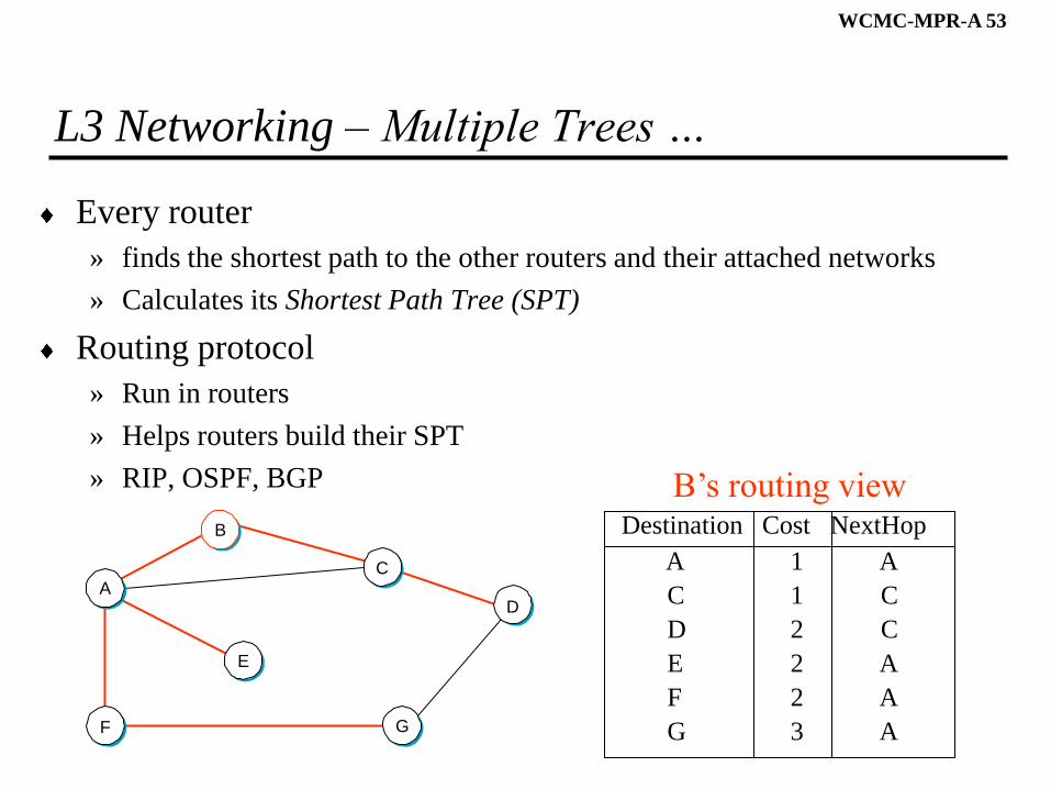
L3 Networking – Multiple Trees …
Every router
» finds the shortest path to the other routers and their attached networks
» Calculates its Shortest Path Tree (SPT)
Routing protocol
» Run in routers
» Helps routers build their SPT
» RIP, OSPF, BGP
Destination Cost NextHop
A 1 A
C 1 C
D 2 C
E 2 A
F 2 A
G 3 A
B’s routing view
D
G
A
F
E
B
C
WCMC-MPR-A 54
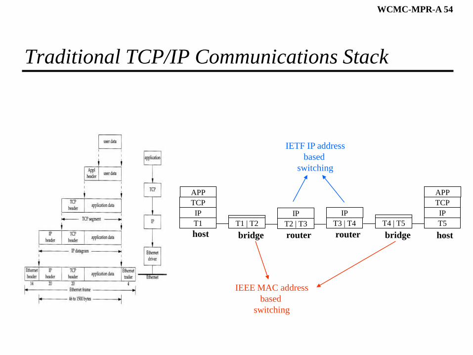
Traditional TCP/IP Communications Stack
T1
IP
TCP
APP
T1 | T2 T2 | T3
IP
T3 | T4
IP
T5
IP
TCP
APP
host bridge router router host
T4 | T5
bridge
IEEE MAC address
based
switching
IETF IP address
based
switching
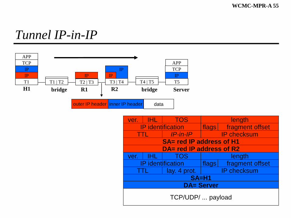
WCMC-MPR-A 55
Tunnel IP-in-IP
T1
IP
TCP
APP
T1 | T2 T2 | T3
IP
T3 | T4 T5
IP
TCP
APP
H1 bridge R1 R2 Server
T4 | T5
bridge
IP IP
IP
outer IP header inner IP header data
DA= red IP address of R2SA= red IP address of H1
TTLIP identification
IP-in-IP IP checksumflags fragment offset
lengthTOSver. IHL
DA= ServerSA=H1
TTLIP identification
lay. 4 prot. IP checksumflags fragment offset
lengthTOSver. IHL
TCP/UDP/ ... payload
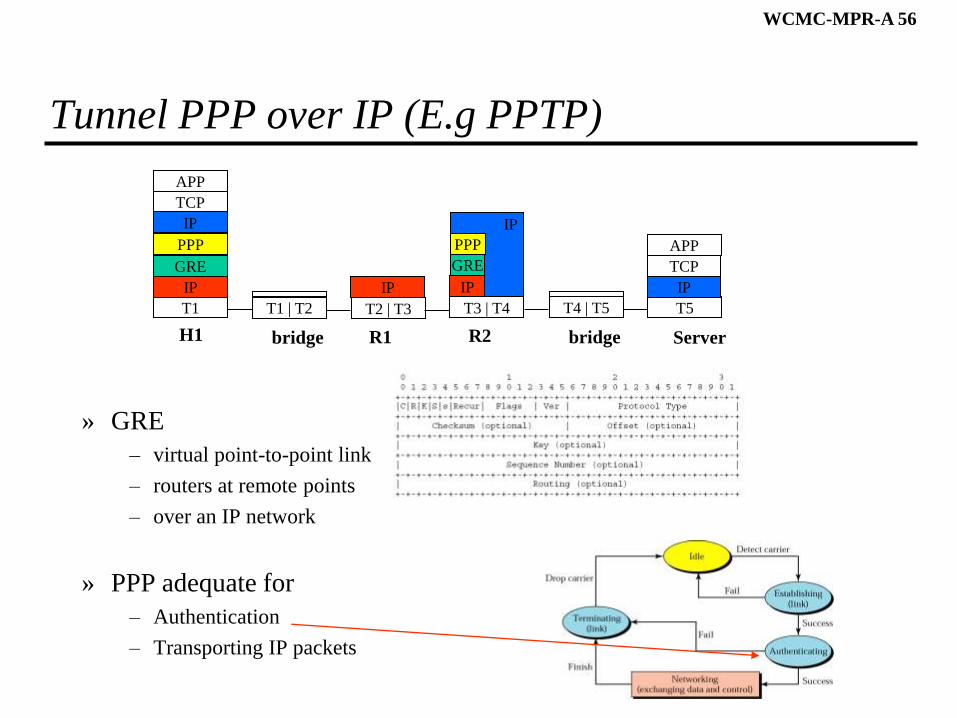
WCMC-MPR-A 56
Tunnel PPP over IP (E.g PPTP)
» GRE
– virtual point-to-point link
– routers at remote points
– over an IP network
» PPP adequate for
– Authentication
– Transporting IP packets
T1
IP
TCP
APP
T1 | T2 T2 | T3
IP
T3 | T4 T5
IP
TCP
APP
H1 bridge R1 R2 Server
T4 | T5
bridge
IP IP
IP
PPP
GREGRE
PPP

WCMC-MPR-A 57
IEEE 802.11
WCMC-MPR-A 58
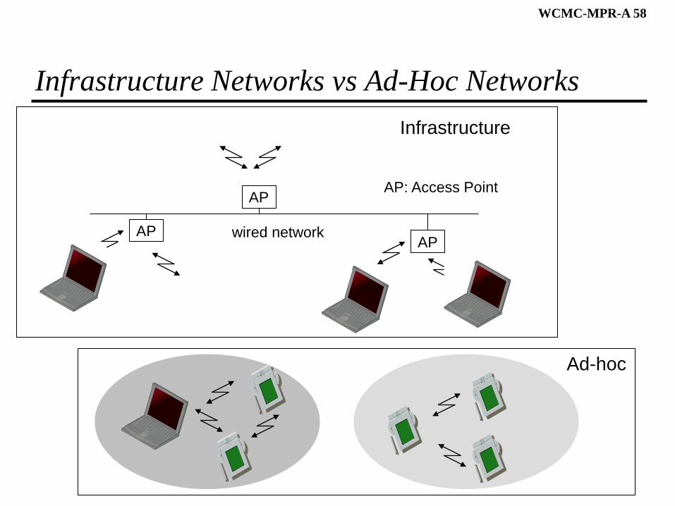
Infrastructure Networks vs Ad-Hoc Networks
Infrastructure
APAP
AP
wired network
AP: Access Point
Ad-hoc
WCMC-MPR-A 59
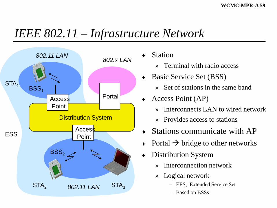
IEEE 802.11 – Infrastructure Network
Station
» Terminal with radio access
Basic Service Set (BSS)
» Set of stations in the same band
Access Point (AP)
» Interconnects LAN to wired network
» Provides access to stations
Stations communicate with AP
Portal bridge to other networks
Distribution System
» Interconnection network
» Logical network
– EES, Extended Service Set
– Based on BSSs
Distribution System
Portal
802.x LAN
Access
Point
802.11 LAN
BSS2
802.11 LAN
BSS1
Access
Point
STA1
STA2 STA3
ESS
WCMC-MPR-A 60
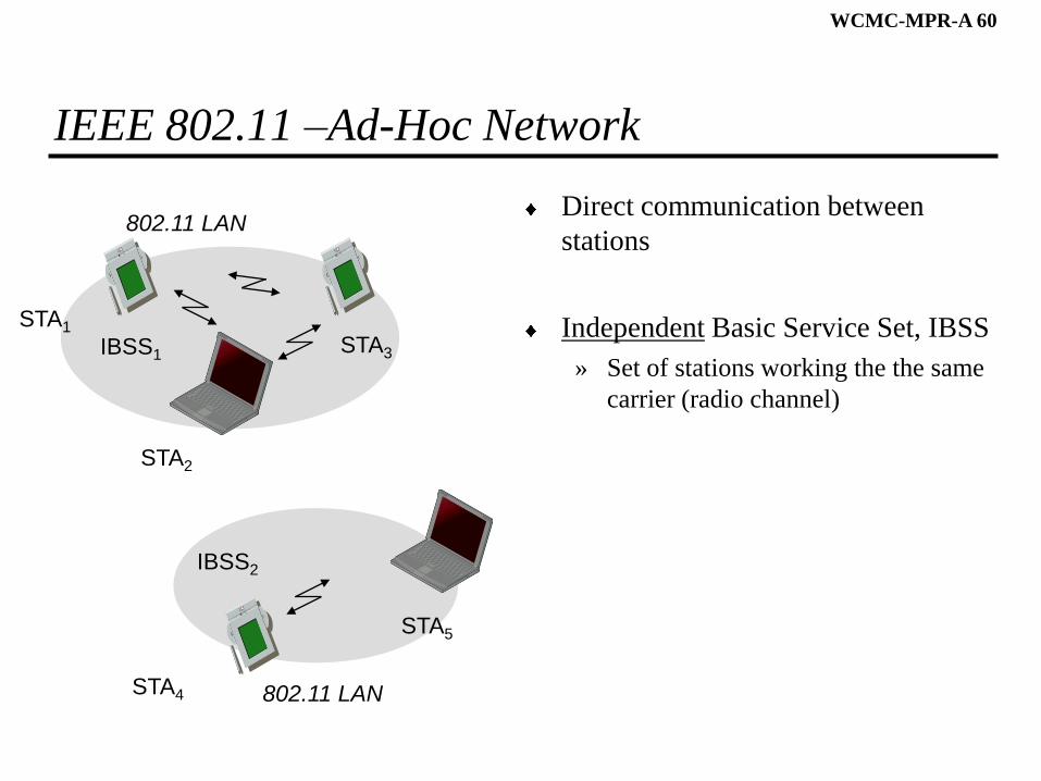
IEEE 802.11 –Ad-Hoc Network
Direct communication between
stations
Independent Basic Service Set, IBSS
» Set of stations working the the same
carrier (radio channel)
802.11 LAN
IBSS2
802.11 LAN
IBSS1
STA1
STA4
STA5
STA2
STA3
WCMC-MPR-A 61
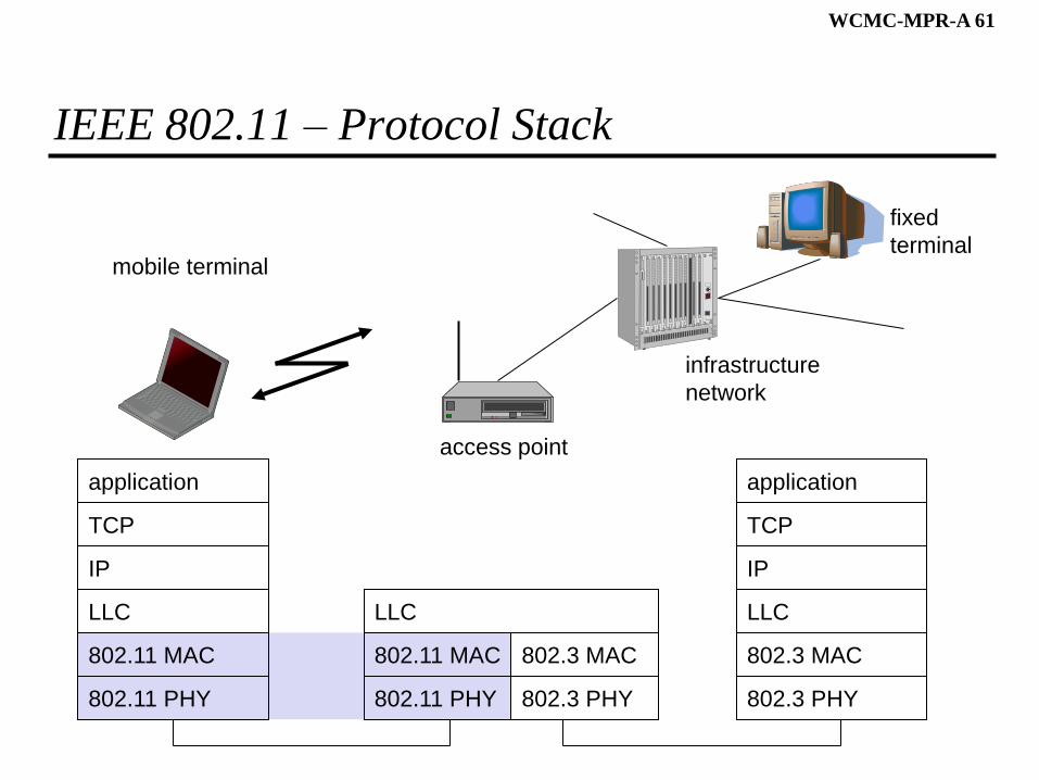
IEEE 802.11 – Protocol Stack
mobile terminal
access point
fixed
terminal
application
TCP
802.11 PHY
802.11 MAC
IP
802.3 MAC
802.3 PHY
application
TCP
802.3 PHY
802.3 MAC
IP
802.11 MAC
802.11 PHY
LLC
infrastructure
network
LLC LLC
WCMC-MPR-A 62
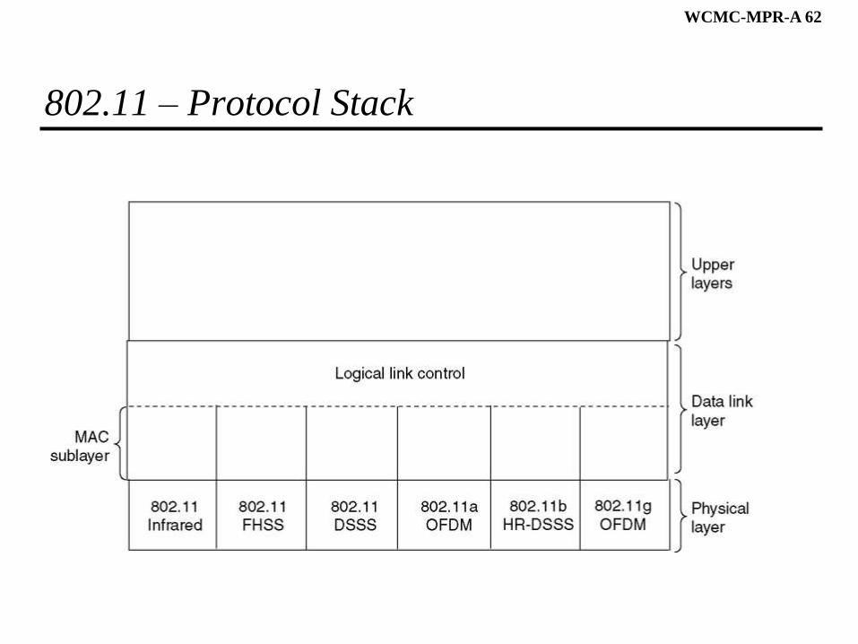
802.11 – Protocol Stack
WCMC-MPR-A 63
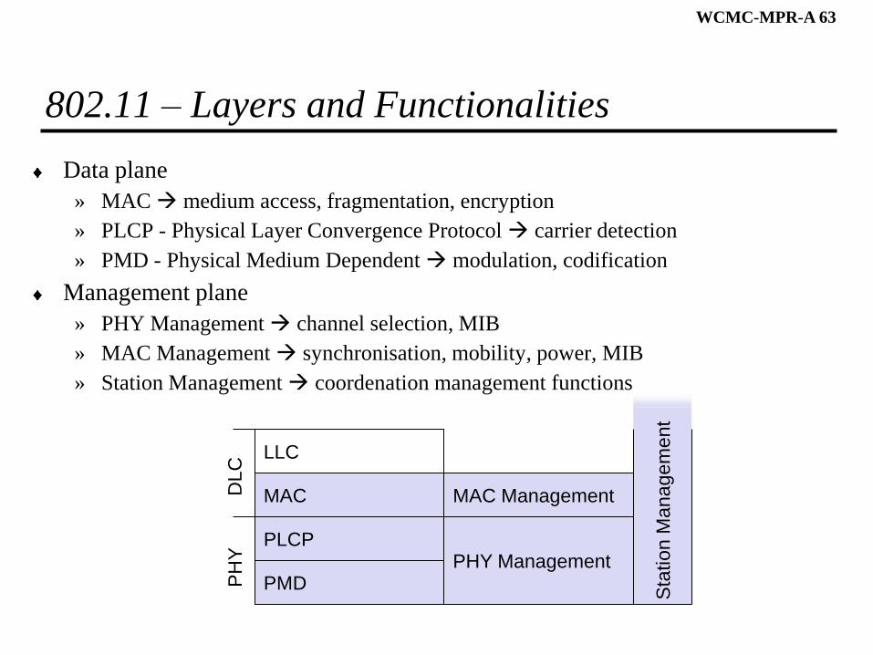
802.11 – Layers and Functionalities
Data plane
» MAC medium access, fragmentation, encryption
» PLCP - Physical Layer Convergence Protocol carrier detection
» PMD - Physical Medium Dependent modulation, codification
Management plane
» PHY Management channel selection, MIB
» MAC Management synchronisation, mobility, power, MIB
» Station Management coordenation management functions
PMD
PLCP
MAC
LLC
MAC Management
PHY Management
PH
YD
LC
Sta
tion M
anag
em
ent
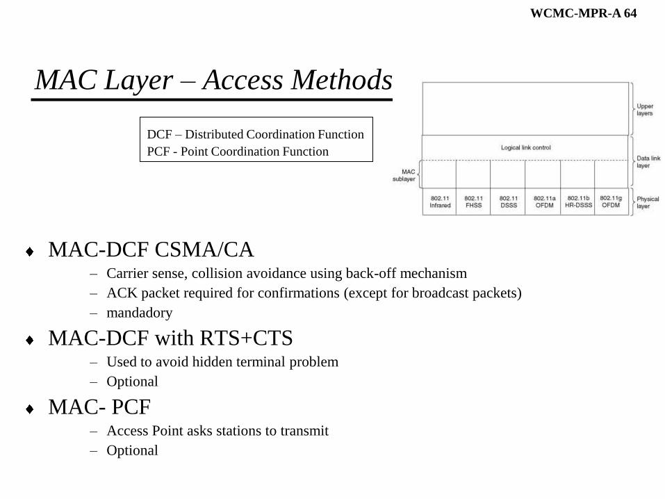
WCMC-MPR-A 64
MAC Layer – Access Methods
MAC-DCF CSMA/CA– Carrier sense, collision avoidance using back-off mechanism
– ACK packet required for confirmations (except for broadcast packets)
– mandadory
MAC-DCF with RTS+CTS– Used to avoid hidden terminal problem
– Optional
MAC- PCF– Access Point asks stations to transmit
– Optional
DCF – Distributed Coordination Function
PCF - Point Coordination Function
WCMC-MPR-A 65
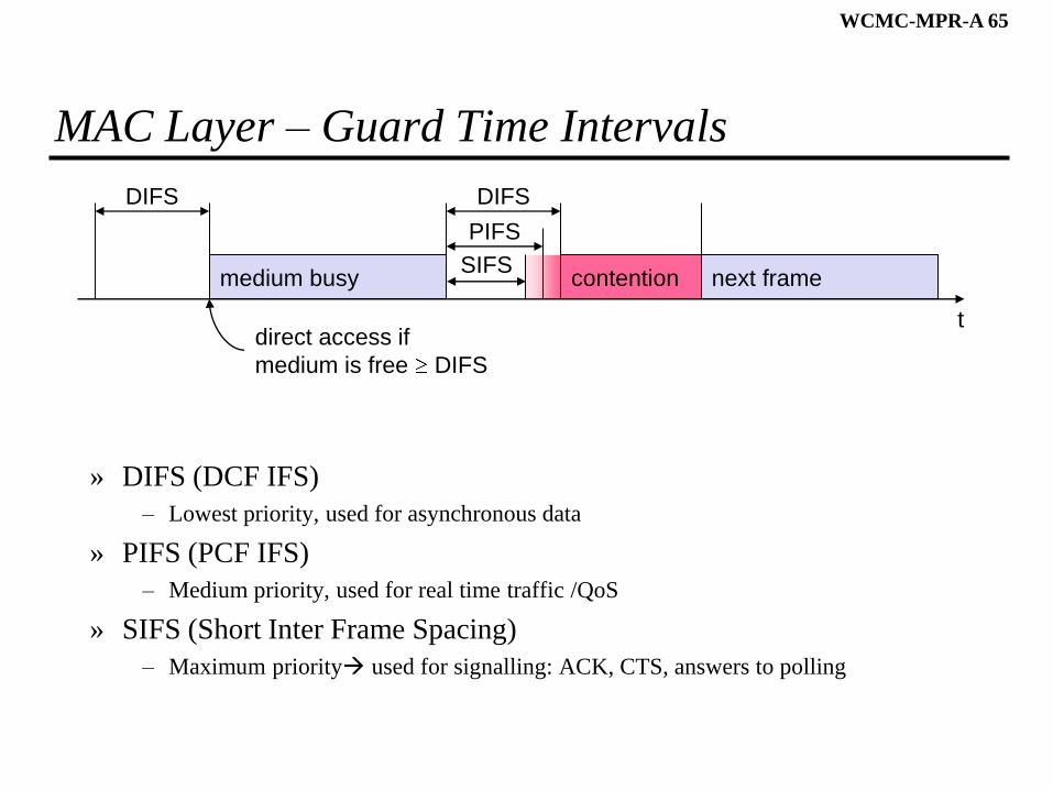
MAC Layer – Guard Time Intervals
» DIFS (DCF IFS)
– Lowest priority, used for asynchronous data
» PIFS (PCF IFS)
– Medium priority, used for real time traffic /QoS
» SIFS (Short Inter Frame Spacing)
– Maximum priority used for signalling: ACK, CTS, answers to polling
t
medium busySIFS
PIFS
DIFSDIFS
next framecontention
direct access if
medium is free DIFS
WCMC-MPR-A 66
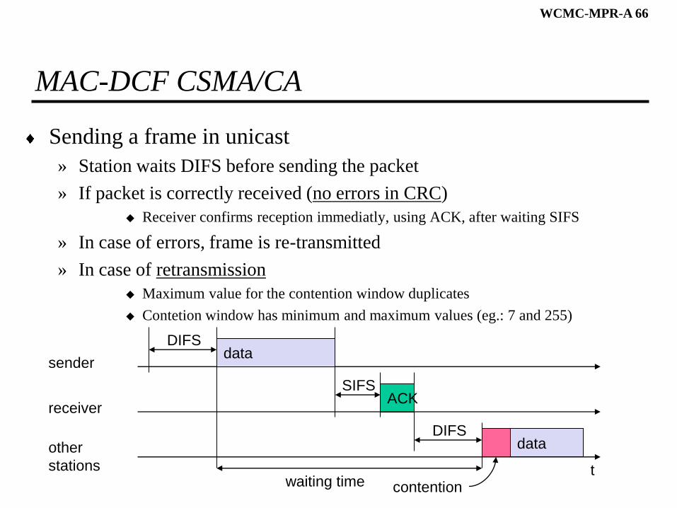
MAC-DCF CSMA/CA
Sending a frame in unicast
» Station waits DIFS before sending the packet
» If packet is correctly received (no errors in CRC)
Receiver confirms reception immediatly, using ACK, after waiting SIFS
» In case of errors, frame is re-transmitted
» In case of retransmission
Maximum value for the contention window duplicates
Contetion window has minimum and maximum values (eg.: 7 and 255)
t
SIFS
DIFS
data
ACK
waiting time
other
stations
receiver
senderdata
DIFS
contention
WCMC-MPR-A 67
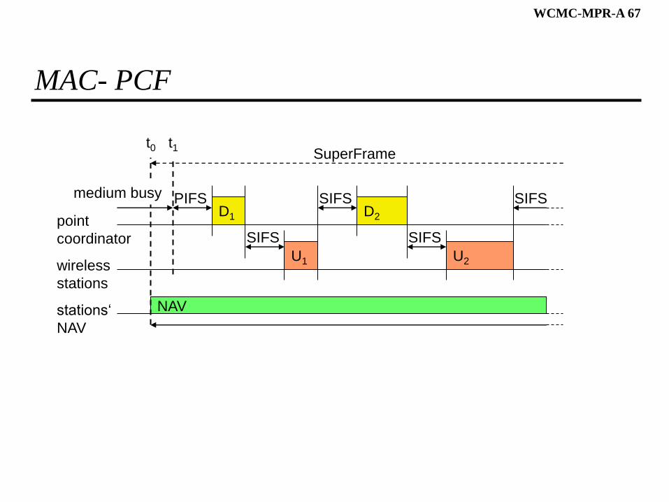
MAC- PCF
PIFS
stations‘
NAV
wireless
stations
point
coordinator
D1
U1
SIFS
NAV
SIFSD2
U2
SIFS
SIFS
SuperFramet0
medium busy
t1
WCMC-MPR-A 68
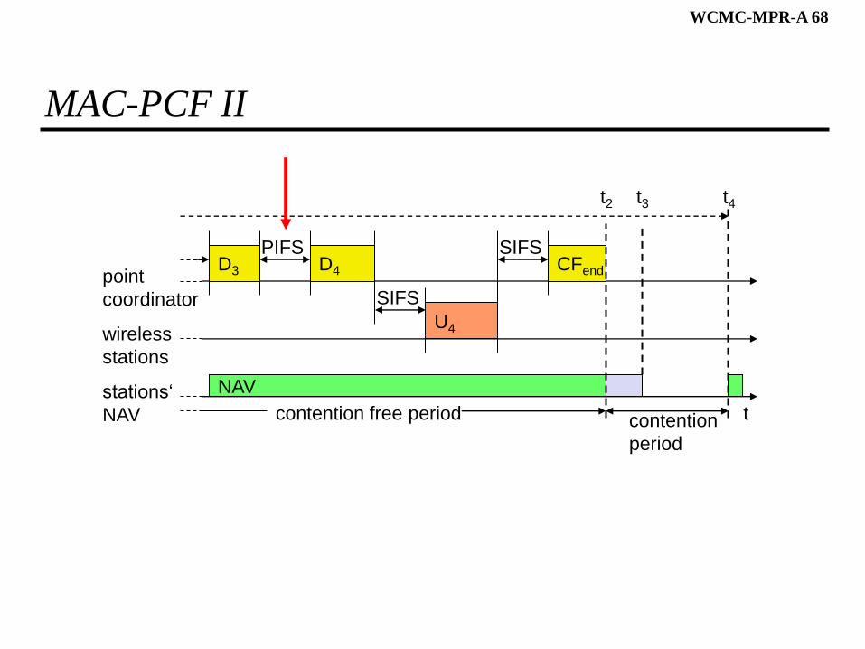
MAC-PCF II
tstations‘
NAV
wireless
stations
point
coordinator
D3
NAV
PIFSD4
U4
SIFS
SIFSCFend
contention
period
contention free period
t2 t3 t4
WCMC-MPR-A 69
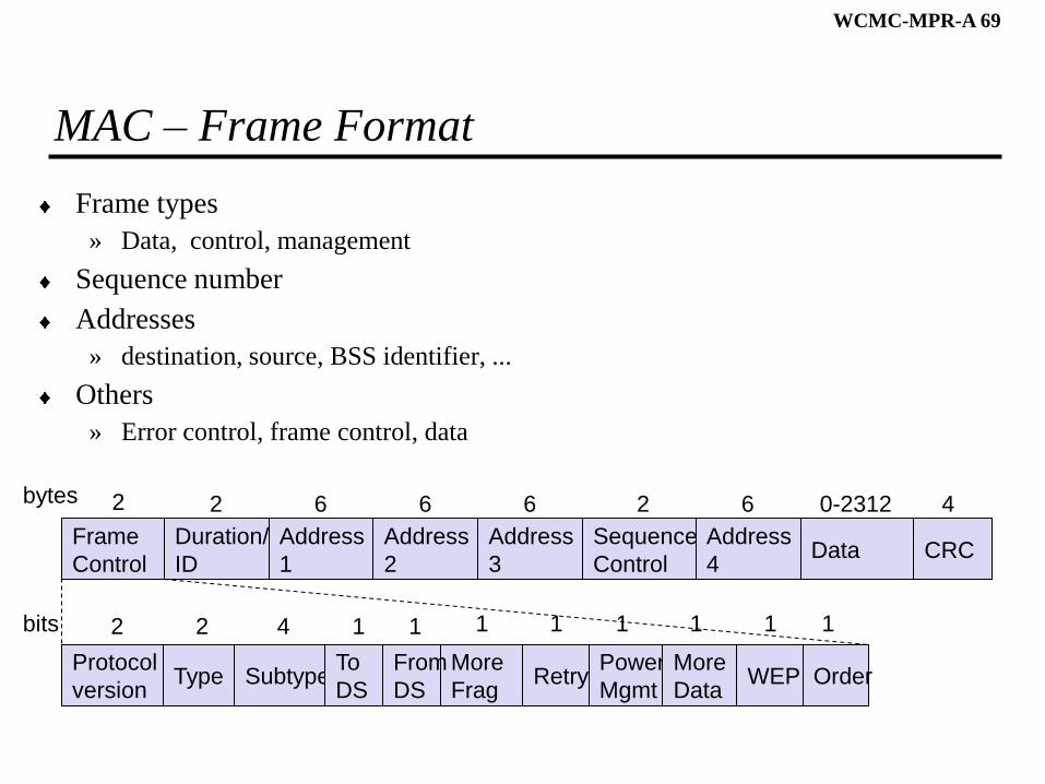
MAC – Frame Format
Frame types
» Data, control, management
Sequence number
Addresses
» destination, source, BSS identifier, ...
Others
» Error control, frame control, data
Frame
Control
Duration/
ID
Address
1
Address
2
Address
3
Sequence
Control
Address
4Data CRC
2 2 6 6 6 62 40-2312bytes
Protocol
versionType Subtype
To
DS
More
FragRetry
Power
Mgmt
More
DataWEP
2 2 4 1
From
DS
1
Order
bits 1 1 1 1 1 1
WCMC-MPR-A 70
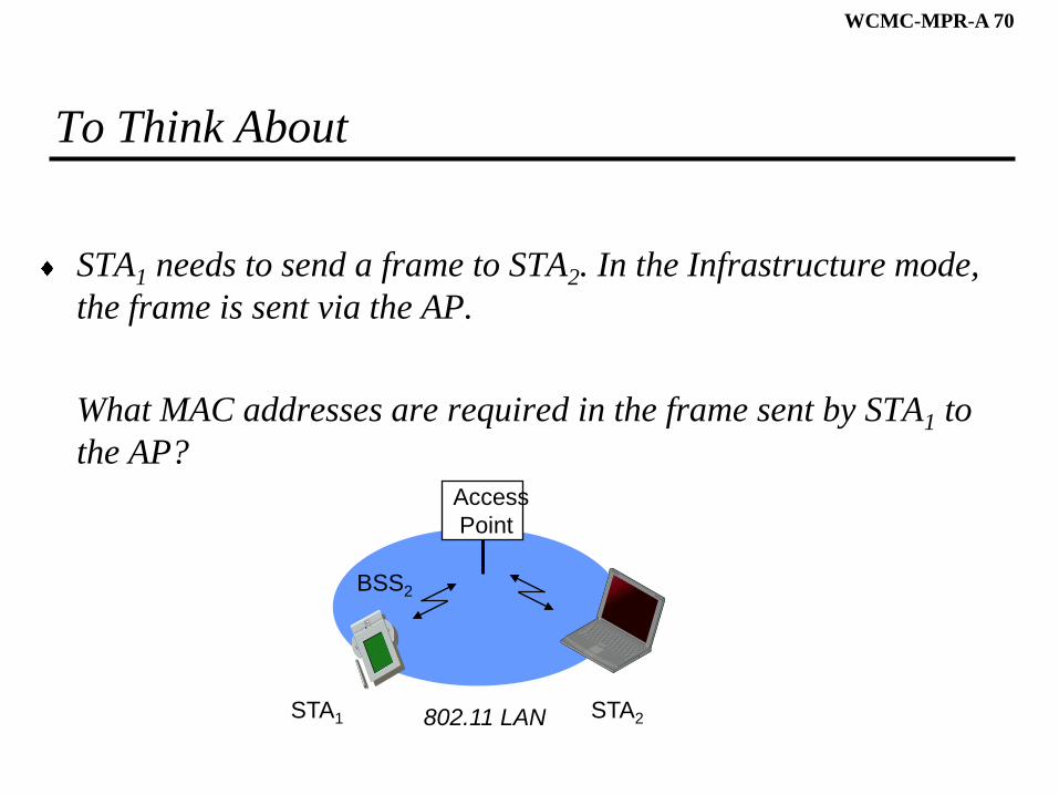
To Think About
STA1 needs to send a frame to STA2. In the Infrastructure mode,
the frame is sent via the AP.
What MAC addresses are required in the frame sent by STA1 to
the AP?
Access
Point
802.11 LAN
BSS2
STA1 STA2
WCMC-MPR-A 71
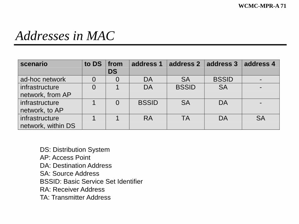
Addresses in MAC
scenario to DS fromDS
address 1 address 2 address 3 address 4
ad-hoc network 0 0 DA SA BSSID -
infrastructurenetwork, from AP
0 1 DA BSSID SA -
infrastructurenetwork, to AP
1 0 BSSID SA DA -
infrastructurenetwork, within DS
1 1 RA TA DA SA
DS: Distribution System
AP: Access Point
DA: Destination Address
SA: Source Address
BSSID: Basic Service Set Identifier
RA: Receiver Address
TA: Transmitter Address
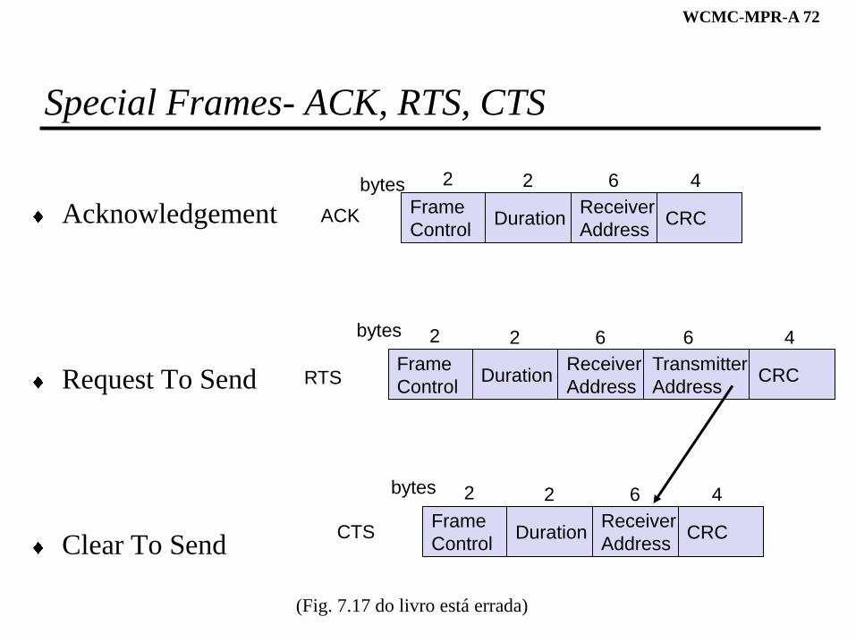
WCMC-MPR-A 72
Special Frames- ACK, RTS, CTS
Acknowledgement
Request To Send
Clear To Send
Frame
ControlDuration
Receiver
Address
Transmitter
AddressCRC
2 2 6 6 4bytes
Frame
ControlDuration
Receiver
AddressCRC
2 2 6 4bytes
Frame
ControlDuration
Receiver
AddressCRC
2 2 6 4bytes
ACK
RTS
CTS
(Fig. 7.17 do livro está errada)
WCMC-MPR-A 73
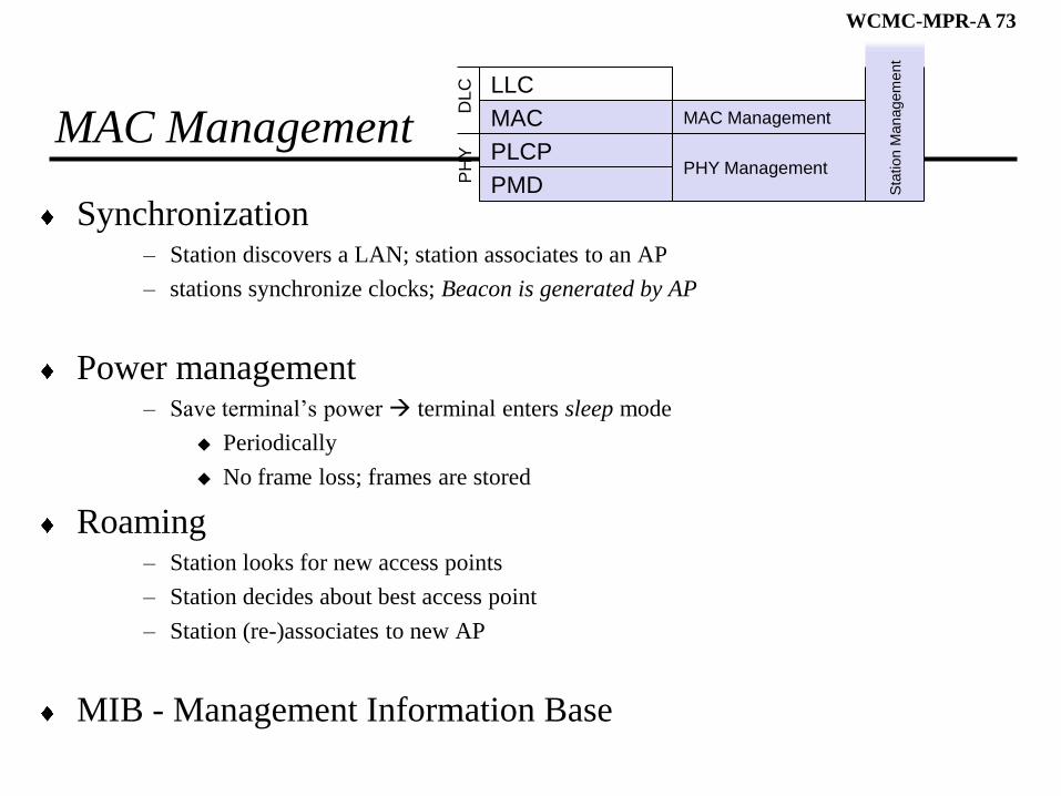
MAC Management
Synchronization– Station discovers a LAN; station associates to an AP
– stations synchronize clocks; Beacon is generated by AP
Power management– Save terminal’s power terminal enters sleep mode
Periodically
No frame loss; frames are stored
Roaming– Station looks for new access points
– Station decides about best access point
– Station (re-)associates to new AP
MIB - Management Information Base
PMD
PLCP
MAC
LLC
MAC Management
PHY Management
PH
YD
LC
Sta
tion M
anagem
ent
WCMC-MPR-A 74
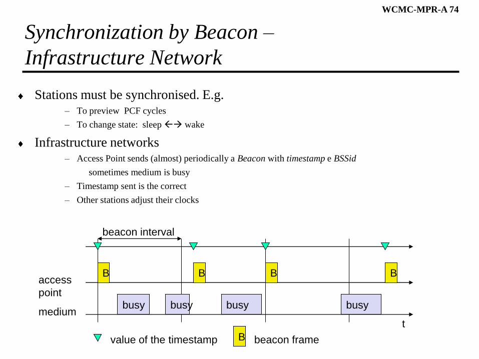
Synchronization by Beacon –
Infrastructure Network
Stations must be synchronised. E.g. – To preview PCF cycles
– To change state: sleep wake
Infrastructure networks– Access Point sends (almost) periodically a Beacon with timestamp e BSSid
sometimes medium is busy
– Timestamp sent is the correct
– Other stations adjust their clocks
beacon interval
tmedium
access
pointbusy
B
busy busy busy
B B B
value of the timestamp B beacon frame
WCMC-MPR-A 75
Power Management
Objective
» If transceiver not in use sleep mode
Station in 2 states: sleep, wake
Infrastructure network
» Stations wake periodically and simultaneously
» They listen beacon to know if there are packets to receive
» If a station has packets to receive remains awake until it receives them– If not, go sleep; after sending its packets!
WCMC-MPR-A 76
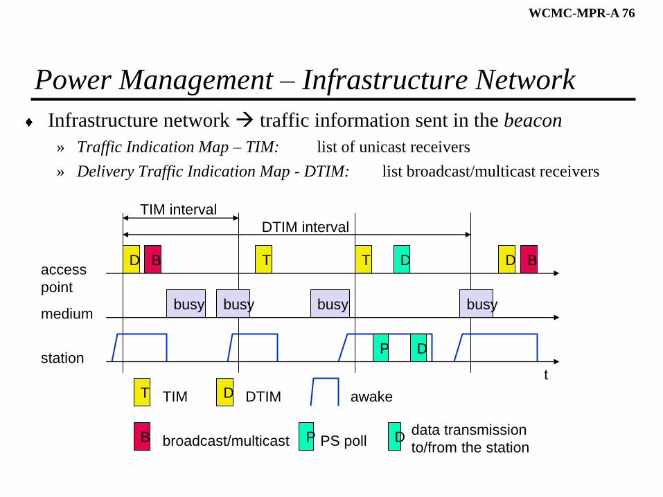
Power Management – Infrastructure Network
Infrastructure network traffic information sent in the beacon
» Traffic Indication Map – TIM: list of unicast receivers
» Delivery Traffic Indication Map - DTIM: list broadcast/multicast receivers
TIM interval
t
medium
access
pointbusy
D
busy busy busy
T T D
T TIM D DTIM
DTIM interval
BB
B broadcast/multicast
station
awake
P PS poll
P
D
D
Ddata transmission
to/from the station
WCMC-MPR-A 77
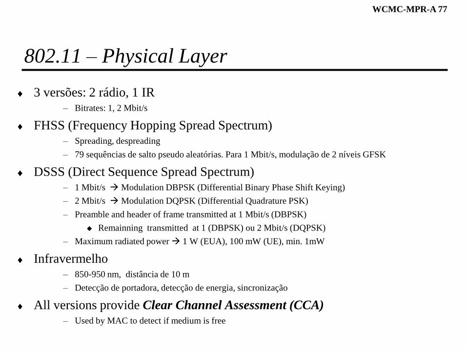
802.11 – Physical Layer
3 versões: 2 rádio, 1 IR– Bitrates: 1, 2 Mbit/s
FHSS (Frequency Hopping Spread Spectrum)– Spreading, despreading
– 79 sequências de salto pseudo aleatórias. Para 1 Mbit/s, modulação de 2 níveis GFSK
DSSS (Direct Sequence Spread Spectrum)– 1 Mbit/s Modulation DBPSK (Differential Binary Phase Shift Keying)
– 2 Mbit/s Modulation DQPSK (Differential Quadrature PSK)
– Preamble and header of frame transmitted at 1 Mbit/s (DBPSK)
Remainning transmitted at 1 (DBPSK) ou 2 Mbit/s (DQPSK)
– Maximum radiated power 1 W (EUA), 100 mW (UE), min. 1mW
Infravermelho– 850-950 nm, distância de 10 m
– Detecção de portadora, detecção de energia, sincronização
All versions provide Clear Channel Assessment (CCA) – Used by MAC to detect if medium is free
WCMC-MPR-A 78
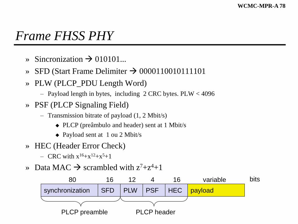
Frame FHSS PHY
» Sincronization 010101...
» SFD (Start Frame Delimiter 0000110010111101
» PLW (PLCP_PDU Length Word)
– Payload length in bytes, including 2 CRC bytes. PLW < 4096
» PSF (PLCP Signaling Field)
– Transmission bitrate of payload (1, 2 Mbit/s)
PLCP (preâmbulo and header) sent at 1 Mbit/s
Payload sent at 1 ou 2 Mbit/s
» HEC (Header Error Check)
– CRC with x16+x12+x5+1
» Data MAC scrambled with z7+z4+1
synchronization SFD PLW PSF HEC payload
PLCP preamble PLCP header
80 16 12 4 16 variable bits
WCMC-MPR-A 79
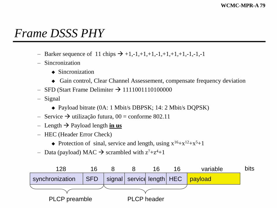
Frame DSSS PHY
– Barker sequence of 11 chips +1,-1,+1,+1,-1,+1,+1,+1,-1,-1,-1
– Sincronization
Sincronization
Gain control, Clear Channel Assessement, compensate frequency deviation
– SFD (Start Frame Delimiter 1111001110100000
– Signal
Payload bitrate (0A: 1 Mbit/s DBPSK; 14: 2 Mbit/s DQPSK)
– Service utilização futura, 00 = conforme 802.11
– Length Payload length in us
– HEC (Header Error Check)
Protection of sinal, service and length, using x16+x12+x5+1
– Data (payload) MAC scrambled with z7+z4+1
synchronization SFD signal service HEC payload
PLCP preamble PLCP header
128 16 8 8 16 variable bits
length
16
WCMC-MPR-A 80
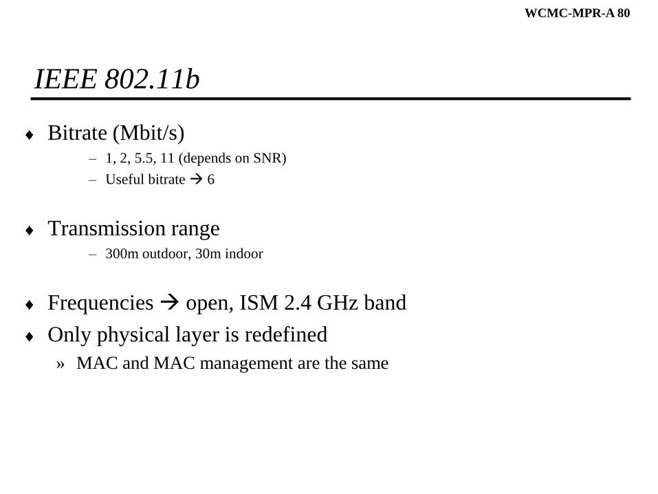
IEEE 802.11b
Bitrate (Mbit/s)– 1, 2, 5.5, 11 (depends on SNR)
– Useful bitrate 6
Transmission range – 300m outdoor, 30m indoor
Frequencies open, ISM 2.4 GHz band
Only physical layer is redefined
» MAC and MAC management are the same
WCMC-MPR-A 81
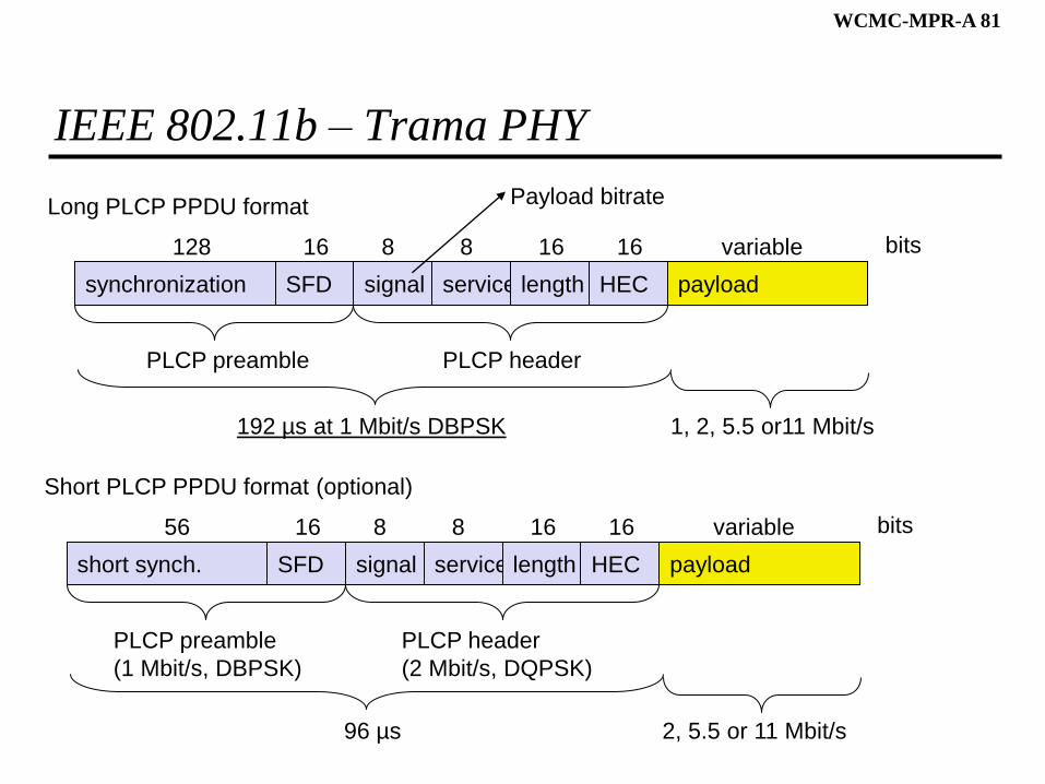
IEEE 802.11b – Trama PHY
synchronization SFD signal service HEC payload
PLCP preamble PLCP header
128 16 8 8 16 variable bits
length
16
192 µs at 1 Mbit/s DBPSK 1, 2, 5.5 or11 Mbit/s
short synch. SFD signal service HEC payload
PLCP preamble
(1 Mbit/s, DBPSK)
PLCP header
(2 Mbit/s, DQPSK)
56 16 8 8 16 variable bits
length
16
96 µs 2, 5.5 or 11 Mbit/s
Long PLCP PPDU format
Short PLCP PPDU format (optional)
Payload bitrate
WCMC-MPR-A 82
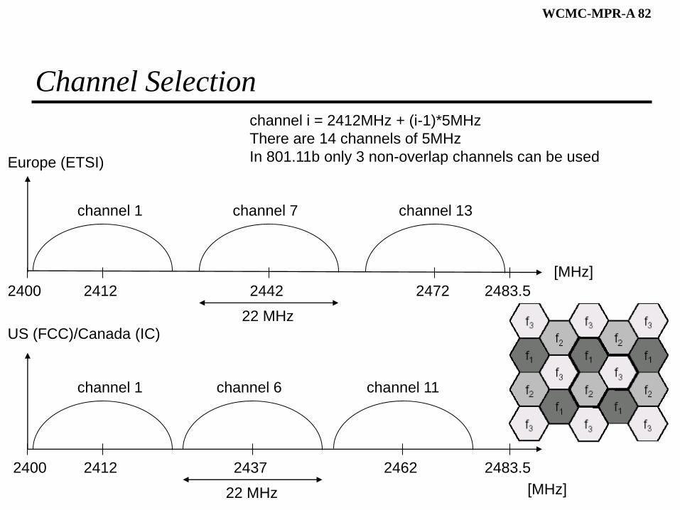
Channel Selection
2400
[MHz]
2412 2483.52442 2472
channel 1 channel 7 channel 13
Europe (ETSI)
US (FCC)/Canada (IC)
2400
[MHz]
2412 2483.52437 2462
channel 1 channel 6 channel 11
22 MHz
22 MHz
channel i = 2412MHz + (i-1)*5MHz
There are 14 channels of 5MHz
In 801.11b only 3 non-overlap channels can be used
WCMC-MPR-A 83
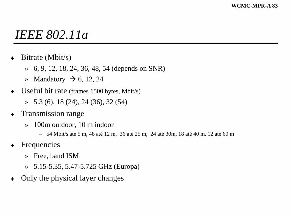
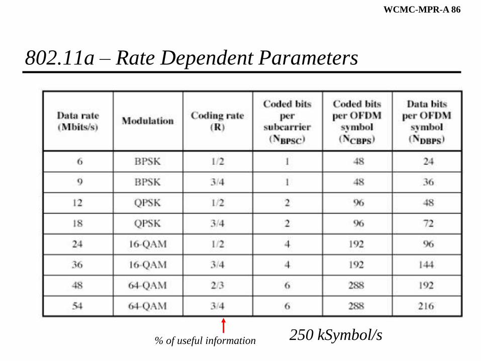
IEEE 802.11a
Bitrate (Mbit/s)
» 6, 9, 12, 18, 24, 36, 48, 54 (depends on SNR)
» Mandatory 6, 12, 24
Useful bit rate (frames 1500 bytes, Mbit/s)
» 5.3 (6), 18 (24), 24 (36), 32 (54)
Transmission range
» 100m outdoor, 10 m indoor
– 54 Mbit/s até 5 m, 48 até 12 m, 36 até 25 m, 24 até 30m, 18 até 40 m, 12 até 60 m
Frequencies
» Free, band ISM
» 5.15-5.35, 5.47-5.725 GHz (Europa)
Only the physical layer changes
WCMC-MPR-A 84
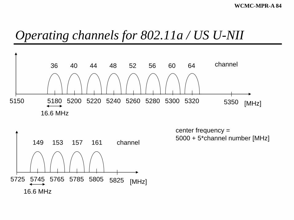
Operating channels for 802.11a / US U-NII
5150 [MHz]5180 53505200
36 44
16.6 MHz
center frequency =
5000 + 5*channel number [MHz]
channel40 48 52 56 60 64
149 153 157 161
5220 5240 5260 5280 5300 5320
5725 [MHz]5745 58255765
16.6 MHz
channel
5785 5805
WCMC-MPR-A 85
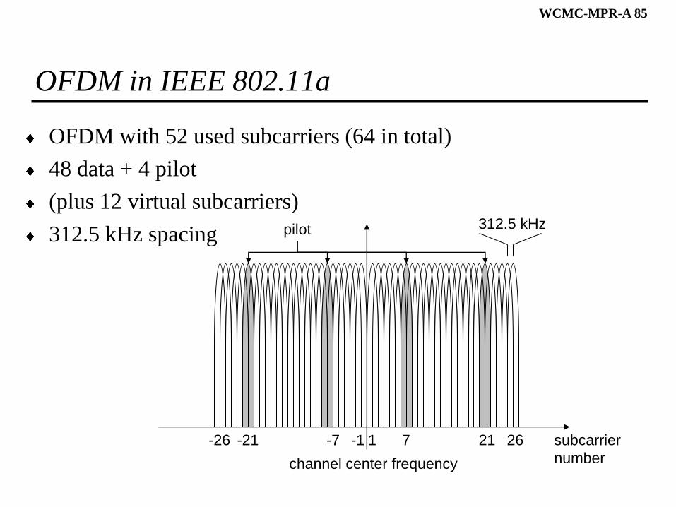
OFDM in IEEE 802.11a
OFDM with 52 used subcarriers (64 in total)
48 data + 4 pilot
(plus 12 virtual subcarriers)
312.5 kHz spacing
subcarrier
number
1 7 21 26-26 -21 -7 -1
channel center frequency
312.5 kHzpilot
WCMC-MPR-A 86
802.11a – Rate Dependent Parameters
250 kSymbol/s% of useful information
WCMC-MPR-A 87
IEEE 802.16
WCMC-MPR-A 88
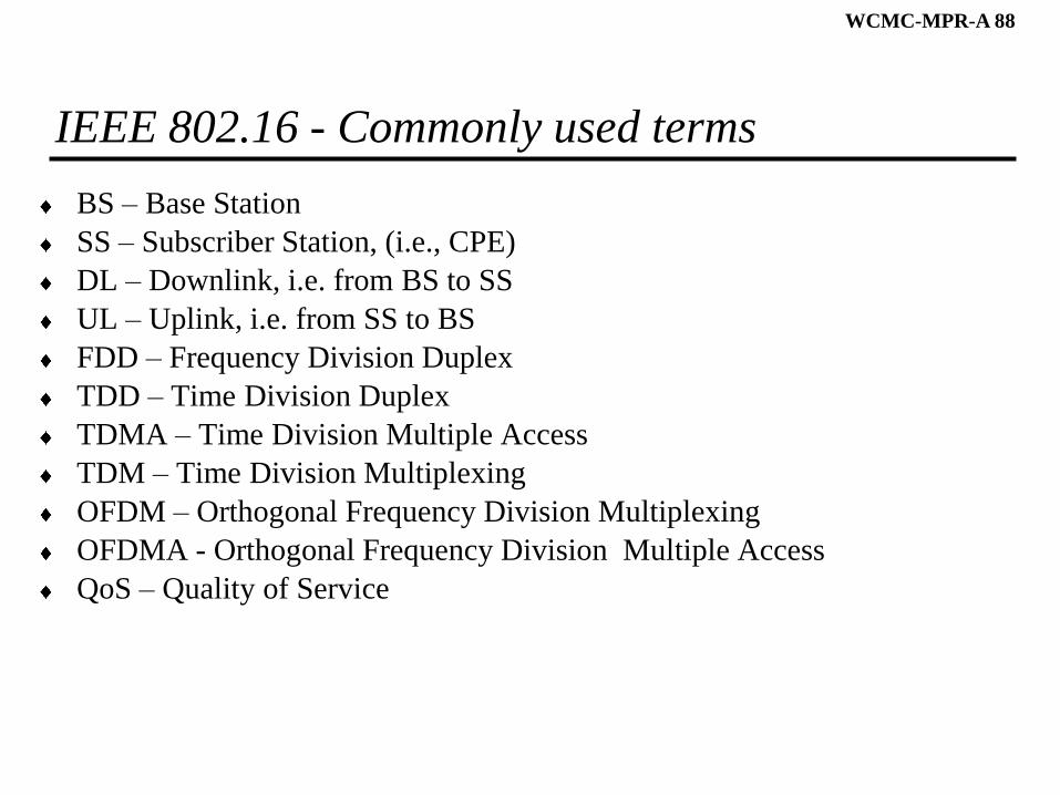
IEEE 802.16 - Commonly used terms
BS – Base Station
SS – Subscriber Station, (i.e., CPE)
DL – Downlink, i.e. from BS to SS
UL – Uplink, i.e. from SS to BS
FDD – Frequency Division Duplex
TDD – Time Division Duplex
TDMA – Time Division Multiple Access
TDM – Time Division Multiplexing
OFDM – Orthogonal Frequency Division Multiplexing
OFDMA - Orthogonal Frequency Division Multiple Access
QoS – Quality of Service
WCMC-MPR-A 89
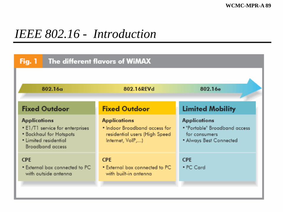
IEEE 802.16 - Introduction
Source: WiMAX, making ubiquitous high-speed data services a reality, White Paper, Alcatel.
WCMC-MPR-A 90
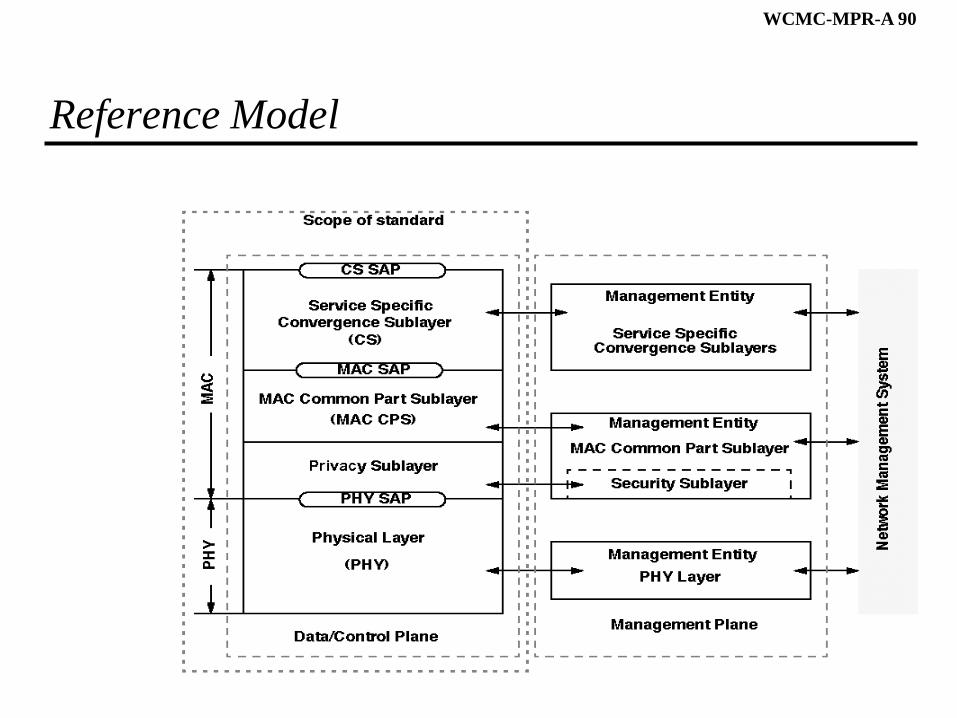
Reference Model
WCMC-MPR-A 91
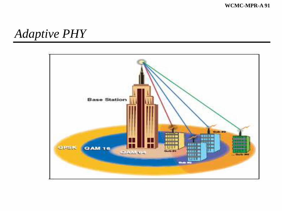
Adaptive PHY
Source: Understanding WiMAX and 3G for Portable/Mobile Broadband Wireless, Technical White Paper, Intel.
WCMC-MPR-A 92
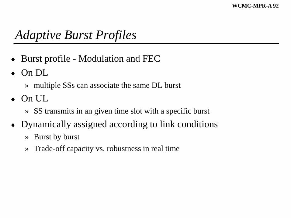
Adaptive Burst Profiles
Burst profile - Modulation and FEC
On DL
» multiple SSs can associate the same DL burst
On UL
» SS transmits in an given time slot with a specific burst
Dynamically assigned according to link conditions
» Burst by burst
» Trade-off capacity vs. robustness in real time
WCMC-MPR-A 93
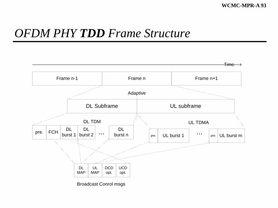
OFDM PHY TDD Frame Structure
DL Subframe
Frame n-1
pre.
Time
Adaptive
Frame n Frame n+1
UL subframe
FCHDL
burst 1
DL
burst n
UL
MAP
Broadcast Conrol msgs
...UL burst 1 UL burst m
DL
MAP
DCD
opt.
UCD
opt.
...DL
burst 2
UL TDMADL TDM
pre. pre.
WCMC-MPR-A 94
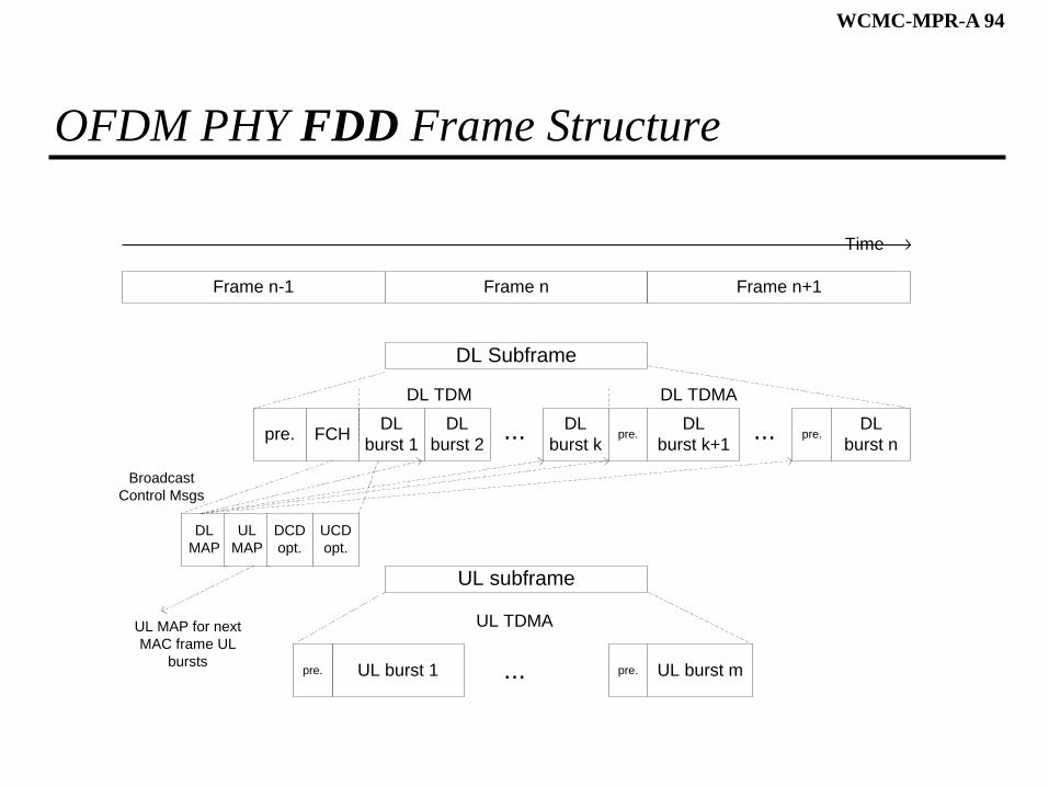
OFDM PHY FDD Frame Structure
DL Subframe
Frame n-1
pre.
Time
Broadcast
Control Msgs
Frame n Frame n+1
UL subframe
FCHDL
burst 1
DL
burst k...
DL TDMA
UL burst 1 UL burst m
DL
burst 2
DL
burst n
DL
burst k+1...
DL TDM
...
UL TDMA
DL
MAP
UL
MAP
DCD
opt.
UCD
opt.
pre.pre.
UL MAP for next
MAC frame UL
burstspre. pre.
WCMC-MPR-A 95
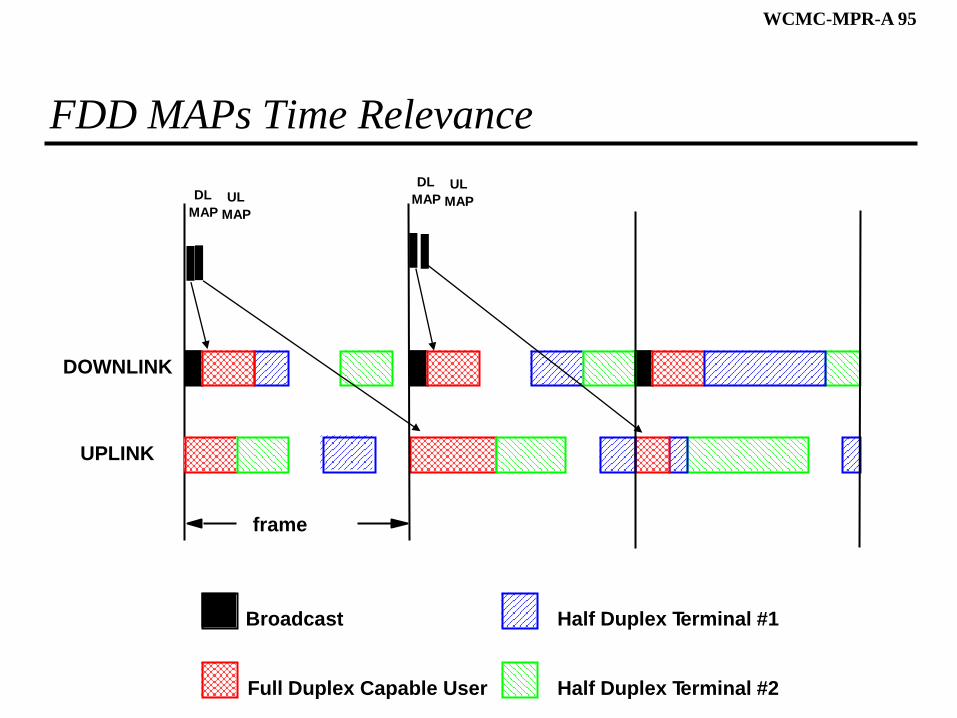
FDD MAPs Time Relevance
frame
Broadcast
Full Duplex Capable User
Half Duplex Terminal #1
Half Duplex Terminal #2
UPLINK
DOWNLINK
DL
MAPUL
MAP
DL
MAPUL
MAP
WCMC-MPR-A 96
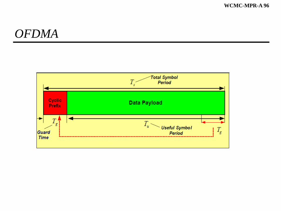
OFDMA
WCMC-MPR-A 97
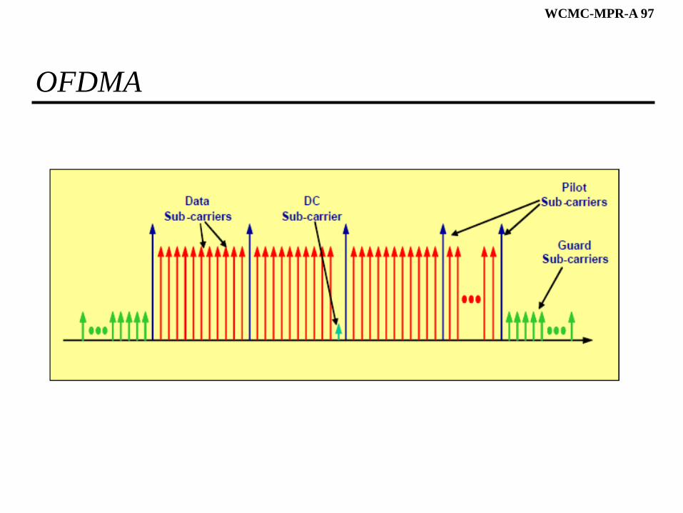
OFDMA
WCMC-MPR-A 98
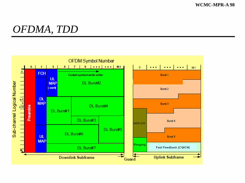
OFDMA, TDD
WCMC-MPR-A 99
IEEE 802.16 MAC Addressing and Identifiers
SS has 48-bit IEEE MAC address
BS has 48-bit base station ID
» Not a MAC address; 24-bit operator indicator
16-bit connection ID (CID)
32-bit service flow ID (SFID)
16-bit security association ID (SAID)
WCMC-MPR-A 100
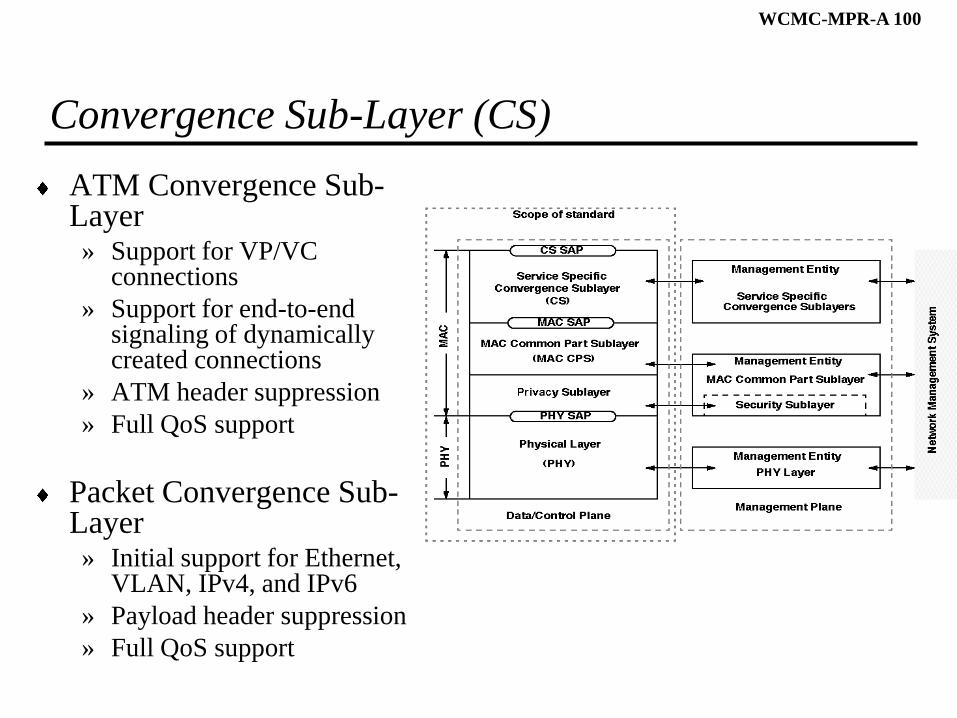
Convergence Sub-Layer (CS)
ATM Convergence Sub-Layer» Support for VP/VC
connections
» Support for end-to-end signaling of dynamically created connections
» ATM header suppression
» Full QoS support
Packet Convergence Sub-Layer» Initial support for Ethernet,
VLAN, IPv4, and IPv6
» Payload header suppression
» Full QoS support
WCMC-MPR-A 101
MAC – CPS – Data Packet Encapsulations
P
H
SI
MAC PDU
Ethernet Packet
Ethernet Packet
Packet PDU
(e.g., Ethernet)
CS PDU
(i.e., MAC SDU)
HT
FEC block 1
CRCMAC PDU Payload
OFDM
symbol
1
PHY Burst(e.g., TDMA burst)
Preamble
OFDM
symbol
2
OFDM
symbol
n
......
FECFEC Block 2 FEC block m
......FEC Block 3
WCMC-MPR-A 102
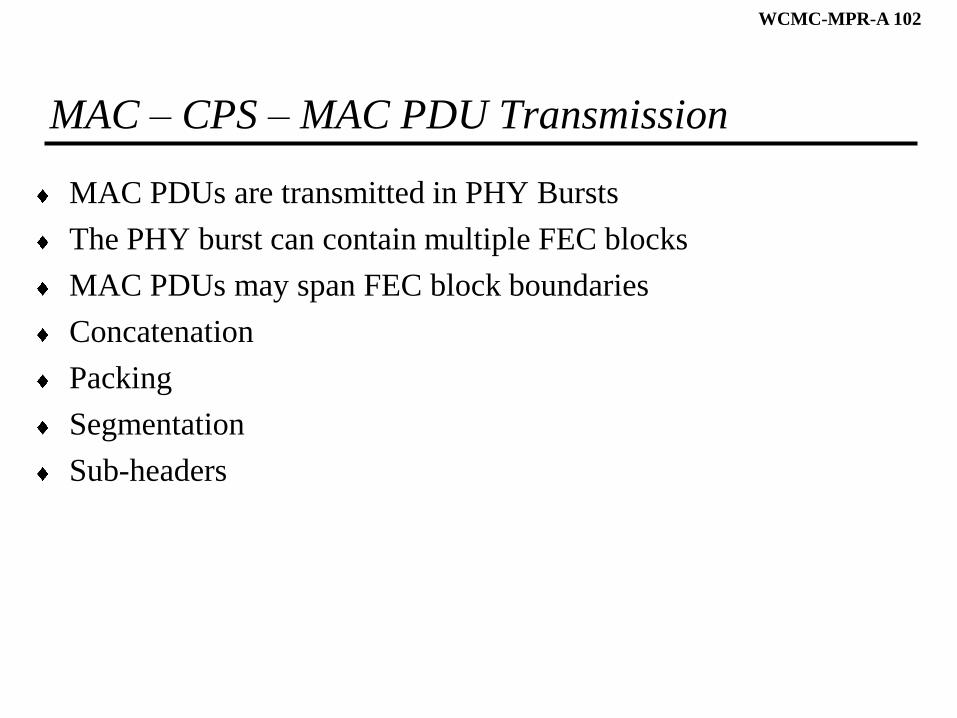
MAC – CPS – MAC PDU Transmission
MAC PDUs are transmitted in PHY Bursts
The PHY burst can contain multiple FEC blocks
MAC PDUs may span FEC block boundaries
Concatenation
Packing
Segmentation
Sub-headers
WCMC-MPR-A 103
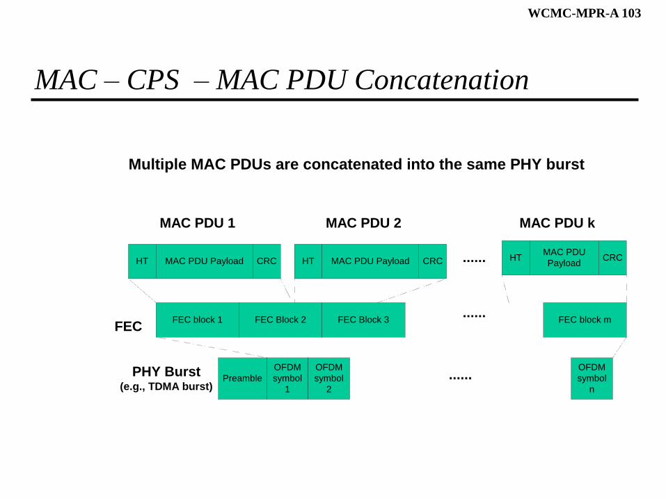
MAC – CPS – MAC PDU Concatenation
MAC PDU 2
HT
FEC block 1
CRCMAC PDU Payload
OFDM
symbol
1
PHY Burst(e.g., TDMA burst)
Preamble
OFDM
symbol
2
OFDM
symbol
n
......
FECFEC Block 2 FEC block m
......FEC Block 3
MAC PDU 1
HT CRCMAC PDU Payload ......
MAC PDU k
HT CRCMAC PDU
Payload
Multiple MAC PDUs are concatenated into the same PHY burst
WCMC-MPR-A 104
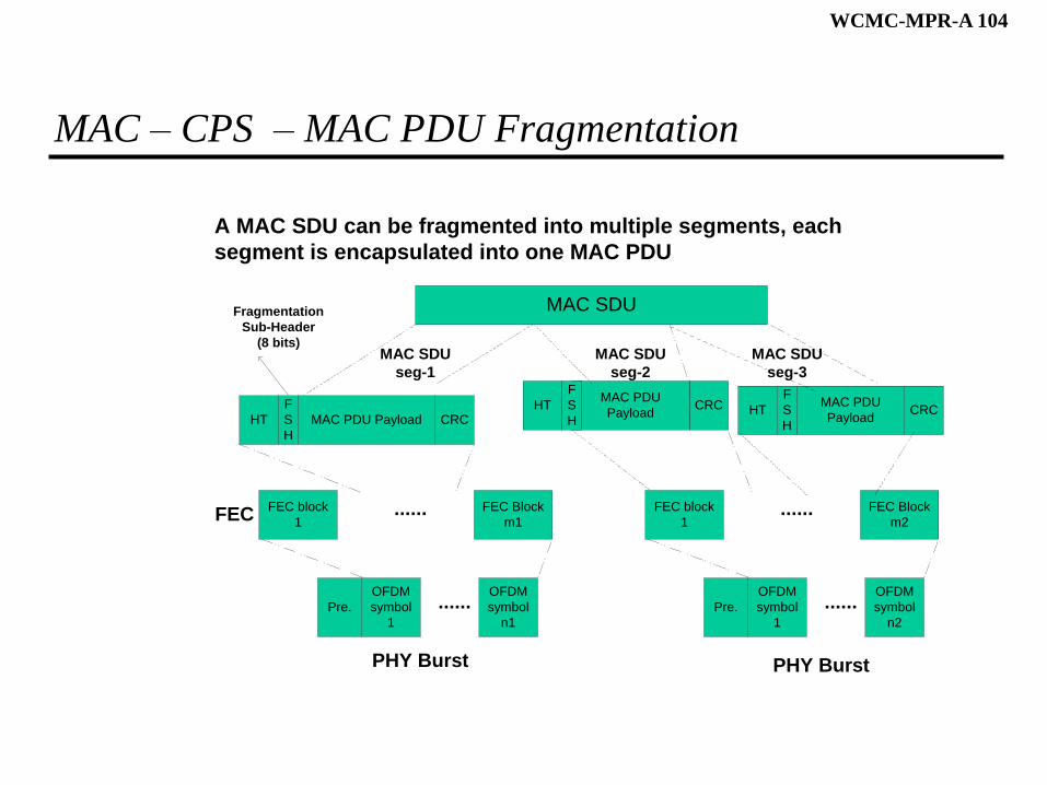
MAC – CPS – MAC PDU Fragmentation
FEC block
1
OFDM
symbol
1
PHY Burst
Pre.
MAC SDU
OFDM
symbol
n1
......
FECFEC Block
m1......
MAC SDU
seg-1
HT CRCMAC PDU PayloadHT CRC
MAC PDU
Payload
A MAC SDU can be fragmented into multiple segments, each
segment is encapsulated into one MAC PDU
FEC block
1
OFDM
symbol
1
PHY Burst
Pre.
OFDM
symbol
n2
......
FEC Block
m2......
HT CRCMAC PDU
Payload
MAC SDU
seg-2
MAC SDU
seg-3
F
S
H
F
S
H
Fragmentation
Sub-Header
(8 bits)
F
S
H
WCMC-MPR-A 105
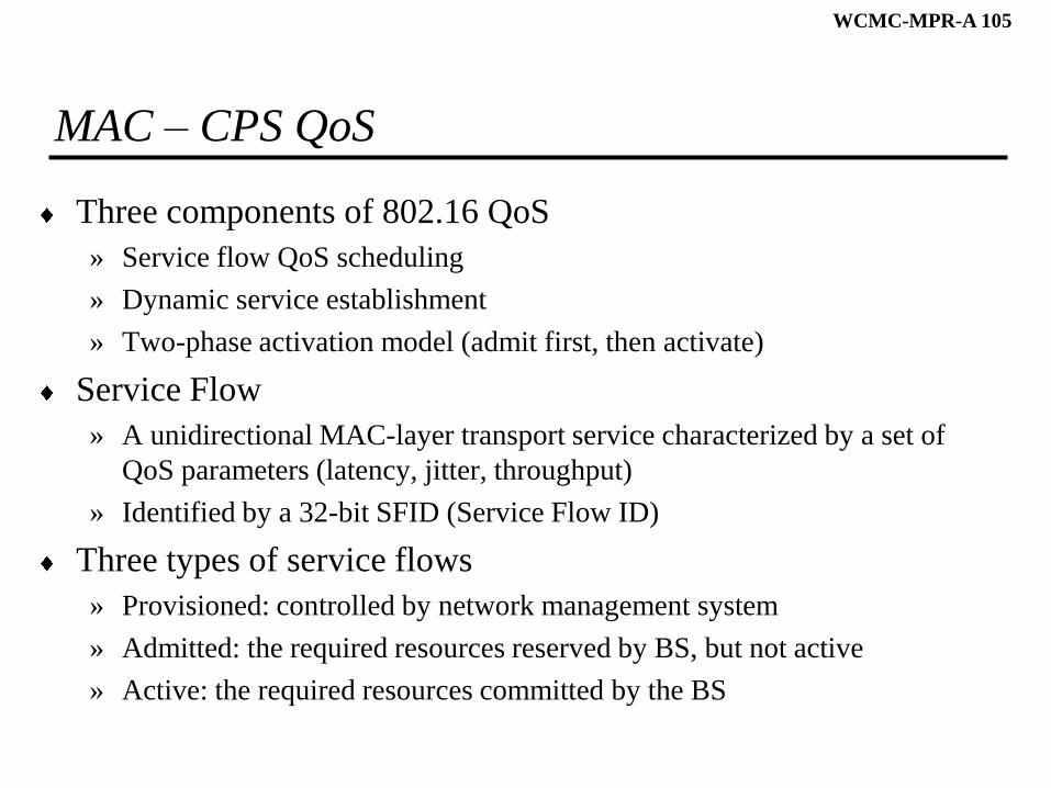
MAC – CPS QoS
Three components of 802.16 QoS
» Service flow QoS scheduling
» Dynamic service establishment
» Two-phase activation model (admit first, then activate)
Service Flow
» A unidirectional MAC-layer transport service characterized by a set of
QoS parameters (latency, jitter, throughput)
» Identified by a 32-bit SFID (Service Flow ID)
Three types of service flows
» Provisioned: controlled by network management system
» Admitted: the required resources reserved by BS, but not active
» Active: the required resources committed by the BS
WCMC-MPR-A 106
MAC – CPS – Uplink Service Classes
UGS: Unsolicited Grant Services
rtPS: Real-time Polling Services
nrtPS: Non-real-time Polling Services
BE: Best Effort
WCMC-MPR-A 107
MAC – CPS – Automatic Repeat reQuest (ARQ)
A Layer-2 sliding-window based flow control mechanism
Per connection basis
Only effective to non-real-time applications
Uses a 11-bit sequence number field
Uses CRC-32 checksum of MAC PDU to check data errors
Maintain the same fragmentation structure for Retransmission
Optional