Embed Size (px)
Citation preview

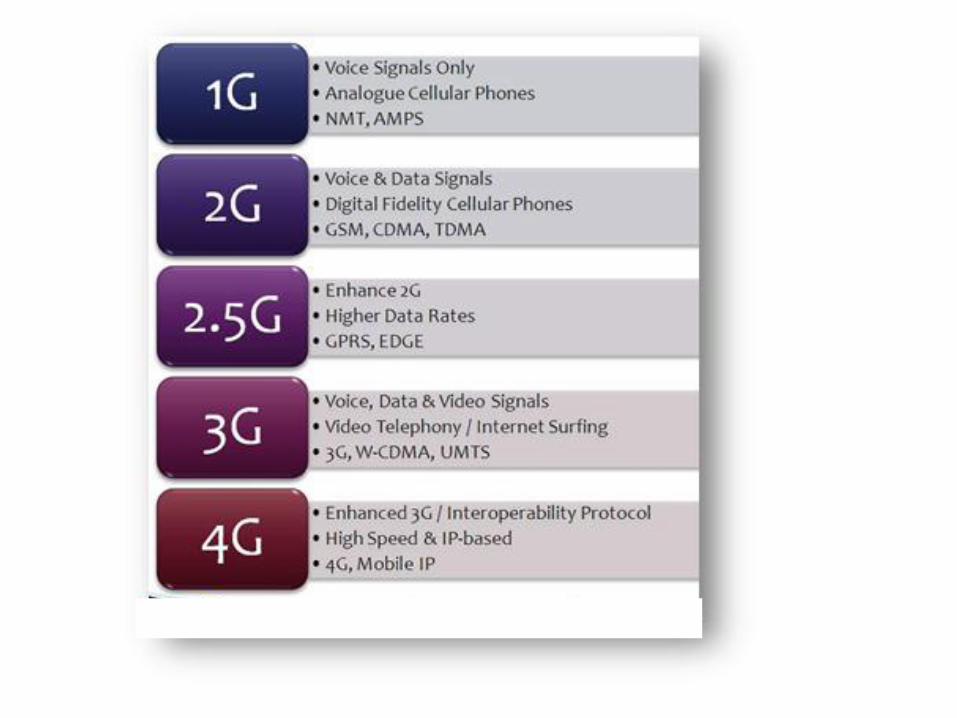
Wireless CommuniCation unit 5

V. ADVANCED TRANSCEIVER SCHEMES
Spread Spectrum Systems- Cellular Code Division Multiple Access
Systems- Principle, Power control, Effects of multipath propagation
on Code Division Multiple Access, Orthogonal Frequency Division
Multiplexing – Principle, Cyclic Prefix, Transceiver implementation,
Second Generation(GSM, IS–95) and Third Generation Wireless
Networks and Standards

G S M
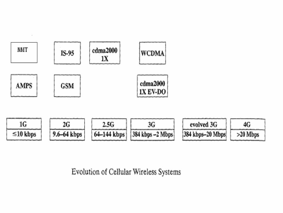
GSM Intro
Global System for Mobile (GSM) is a 2G cellular
standard.
It is the most popular standard.
GSM was first introduced into the European market in
1991

GSM Services
The has 3 main services
1. Telephone services – this refers to the normal
telephone services, in addition to that we have video
calls and teleconferencing calls.
2. Bearer services or data services- GPRS & EDGE
3. Supplementary ISDN services- SMS, call diversion,
closed user groups and caller identification

Key features
1. Subscriber Identity Module (SIM) - a memory device that
stores all the user information
2. On air privacy- The privacy is made possible by
encrypting the digital bit stream sent by a GSM
transmitter. Each user is provided with a unique secret
cryptographic key, that is known only to the cellular
carrier. This key changes with time for each user

GSM SYSTEM ARCHITECTURE

GSM System Architecture
It has 3 sub system
1. Base Station Subsystem (BSS),
2. Network and Switching Subsystem (NSS),
3. Operation Support Subsystem (OSS)
Base Station Subsystem (BSS)
The Mobile Station (MS) is usually considered to be
part of the BSS.
The BSS is also known as the Radio Subsystem
BSS facilitates communication between the mobile
stations and the Mobile Switching Center (MSC).
The Mobile Stations (MS) communicate with the Base
Station Subsystem (BSS) using radio air interface
Each BSS consists of many Base Station Controllers (BSCs)
which connect the MS to the Network and Switching
Subsystem (NSS) via the MSCs
Each BSC typically controls up to several hundred Base
Transceiver Stations (BTSs).
BTSs are connected to the BSC by microwave link or
dedicated leased lines
Handoffs between two BTSs (under same BSC)can be
handled by the BSC instead of the MSC. This greatly
reduces the switching burden of the MSC.

Network and Switching Subsystem (NSS)
The NSS manages the switching functions of the system
and allows the MSCs to communicate with other networks
such as the PSTN and ISDN.
The MSC is the central unit in the NSS and controls the
traffic among all of the BSCs.
Communication between the MSC and the BSS is carried
out by using SS7 protocol.
The NSS handles the switching of calls between external
networks and the BSCs

NSS maintains are three databases for switching operations.
1. Home Location Register (HLR) 2. Visitor Location Register (VLR)3. Authentication Center (AUC)
The HLR contains subscriber information and location
information for each user under a single MSC.
Each subscriber is assigned a unique International Mobile
Subscriber Identity (IMSI), and this number is used to track
each user.

Visitor Location Register (VLR)
This will oversee the operations of a ROAMING mobile.
It temporarily stores the IMSI and customer information of
the roamer.
Once a roaming mobile is logged in the VLR, the MSC
sends the necessary information to the roamer’s HLR so
that calls to the roaming mobile can be appropriately
routed over the PSTN by the roaming user's HLR
Authentication Center
Authentication Center is a strongly protected database
which handles the authentication and encryption keys
for every user in the HLR and VLR.
The Authentication Center contains a register called
the Equipment Identity Register (EIR) which identifies
stolen or fraudulently altered phones

Operation Support Subsystem (OSS)
The OSS has one or more Operation Maintenance
Centers (OMC) ,which will
1. Maintain all telecommunications hardware
and network operations within a particular
market
2. Manage all charging and billing procedures
3. Manage all mobile equipment in the system.
GSM Radio Subsystem
GSM utilizes two bands of 25 MHz (forward andreverse )
The available forward and reverse frequency bands aredivided into 200 kHz wide channels called ARFCNs(Absolute Radio Frequency Channel Numbers).
ARFCN denotes a forward and reverse channel pair
Eight subscribers can use the same ARFCN in differenttime slots.

GSM CHANNELS

GSM Channels
1. Traffic channels (TCH) - carry digitally encoded user
speech or user data
2. Control channels (CCH) - carry signaling and
synchronizing commands between the base station
and the mobile station

GSM Traffic Channels (TCH)
GSM traffic channels may be either
1. Full-rate – input raw data is processed at a rate of13 kbps
2. Half-rate - input raw data is processed at a rate of6.5 kbps

Full-Rate TCH
1. Full-Rate Speech Channel (TCH/FS) — The full-rate
speech channel carries user speech at the rate of
13 kbps. After GSM channel coding the data rate will
be increased to 22.8 kbps.
2. Full-Rate Data Channel for 9600 bps (TCH/F9.6)
— This channel carries raw user data at 9600 bps.
After GSM channel coding the data rate will be
increased to 22.8 kbps.

3. Full-Rate Data Channel for 4800 bps (TCH/F4.8)
— This channel carries raw user data at the rate
4800 bps. Additional forward error correction coding
is applied by the GSM standard, and the 4800 bps
user data is sent at 22.8 kbps.
4. Full-Rate Data Channel for 2400 bps (TCH/F2.4)
— This channel carries raw user data at 2400 bps.
After GSM channel coding the data rate will be
increased to 22.8 kbps.

Half-Rate TCH1. Half-Rate Speech Channel (TCH/HS)
The half-rate speech channel has been designed tocarry digitized speech which is sampled at a rate halfthat of the full-rate channel at 6.5 kbps. After GSMchannel coding the data rate will be increased to 11.4kbps.
2. Half-Rate Data Channel for 4800 bps (TCH/H4.8)Raw user data rate - 4800 bps.After GSM channel coding- 11.4 kbps.
3. Half-Rate Data Channel for 2400 bps (TCH/H2.4)Raw user data rate - 2400 bpsAfter GSM channel coding- 11.4 kbps.

GSM Control Channels (CCH)
Types
1. The Broadcast Channel (BCH)
2. The Common Control Channel (CCCH)
3. The Dedicated Control Channel (DCCH)

1.The Broadcast Channel (BCH)
BCHs only use the forward link and transmits data only in the first time slot (TS 0) of certain GSM frames.
The BCH provides synchronization for all mobiles within the cell
BCH has 3 types
a) Broadcast Control Channel (BCCH)
b) Frequency Correction Channel (FCCH)
c) Synchronization Channel (SCH)
a) Broadcast Control Channel (BCCH)
The BCCH is a forward control channel that is used to
broadcast information such as cell and network
identity, and operating characteristics of the cell
(current control channel structure, channel
availability, and congestion).
The BCCH also broadcasts a list of channels that are
currently in use within the cell

b) Frequency Correction Channel (FCCH)
The FCCH allows each user to synchronize its internal
frequency (local oscillator) to the exact frequency of
the base station.
The FCCH occupies TS 0 for the very first GSM frame
(frame 0) and is repeated every ten frames within a
control channel multiframe .

c) Synchronization Channel (SCH)
SCH is broadcast in TS 0 of the frame immediately
following the FCCH frame and is used to identify the
serving base station while allowing each mobile to frame
synchronize with the base station.
Since a mobile may be as far as 30 km away from a serving
base station, it is often necessary to adjust the timing of a
particular mobile user such that the received signal at the
base station is synchronized with the base station clock.
The SCH is transmitted once every ten frames within the
control channel multiframe

2.The Common Control Channel (CCCH)
a) Paging Channel (PCH)- notifies a mobile of anincoming call originated from the PSTN throughpaging message.
b) Random Access Channel (RACH)- is a reverse linkchannel used by a subscriber to acknowledge apaging message from the PCH, and also used bymobiles to originate a call
c) Access Grant Channel (AGCH)- is used by the basestation to provide forward link to the mobile, andcarries data which instructs the mobile to operate ina particular physical channel.

3.The Dedicated Control Channel (DCCH)
a) Stand-alone Dedicated Control Channels (SDCCH) .
b) Slow Associated Control Channel (SACCH)
c) Fast Associated Control Channels (FACCH)
a) Stand-alone Dedicated Control Channels (SDCCH)
The SDCCH ensures that the mobile station and the base
station remain connected while the base station and MSC
verify the subscriber unit and allocate resources for the
mobile.
The SDCCH can be thought of as an intermediate and
temporary channel which accepts a newly completed call
from the BCH and holds the traffic while waiting for the
base station to allocate a TCH channel

b) Slow Associated Control Channel (SACCH)
On the forward link, the SACCH sends slow but
regularly changing control information to the mobile,
such as transmit power level instructions and specific
timing advance instructions.
The reverse SACCH carries information about the
received signal strength and quality of the TCH, as well
as BCH measurement results from neighboring cells
c) Fast Associated Control Channels (FACCH)
FACCH carries urgent messages such as a handoff
request.
The FACCH gains access to a time slot by "stealing"
frames from the traffic channel
CDMA

Intro
• CDMA is officially termed as Interim Standard 95
(IS-95), it is the first CDMA-based digital cellular
standard by Qualcomm.
• The brand name for IS-95 is cdmaOne.
• CDMA-3G is CDMA2000

Frequency and Channel Specifications
• Reverse Link 824 - 849 MHz & 1850–1910MHz
• Forward Link869 - 894 MHz & 1930–1990MHz
• A forward and reverse channel pair is separated by 45
MHz
• IS-95 specifies two possible speech rates 13.3 or 8.6
kbit/s.
• Channel Chip Rate of 1.2288 Mchip/s
• IS-95 allows each user within a cell to use the
same radio channel, and users in adjacent cells
also use the same radio channel, since this is a
direct sequence spread spectrum CDMA
system.
• CDMA completely eliminates the need for
frequency reuse.

• Each IS-95 channel occupies 1.25 MHz of spectrum on
each one-way link.
• IS-95 uses a different modulation and spreading
technique for the forward and reverse links.
• On the forward link, the base station simultaneously
transmits the user data for all mobiles in the cell by using
a different spreading sequence for each mobile.
• A pilot code is transmitted simultaneously and at a
higher power level, to all mobiles to synchronize with the
carrier frequency.

• On the reverse link, all mobiles respond in an
asynchronous fashion and have ideally a
constant signal level due to power control
applied by the base station.
• Received power is controlled at the base station
to avoid Near-Far Problem.

Speech Coder
• The speech coder used in the IS-95 system is
the Qualcomm 9600 bps Code Excited Linear
Predictive (QCELP) coder
• Intermediate user data rates of 2400 and
4800bps are also used for special purposes
• QCELP13 uses 13.4 kbps of speech data .

Spreading and Modulation
IS-95 uses three types of spreading codes:
1. Walsh codes.
2. Short spreading codes,
3. Long spreading codes,

Walsh codes• Walsh codes will convert messages of length n to codewords of
length 2n
• This is used for forward communication
• Walsh codes are strictly orthogonal codes that can be constructed
systematically using
Walsh–Hadamard matrix
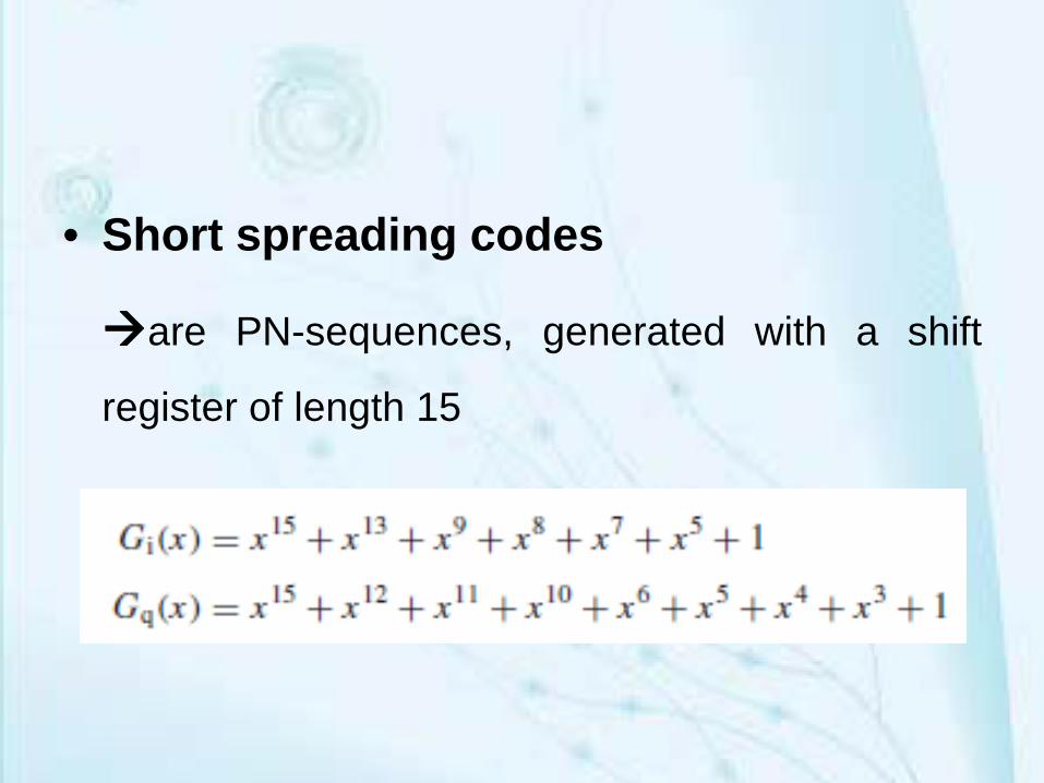
• Short spreading codes
are PN-sequences, generated with a shift
register of length 15

Long Spreading Codes
PN-sequences generated using shift registers
having length 42
The generator polynomial is
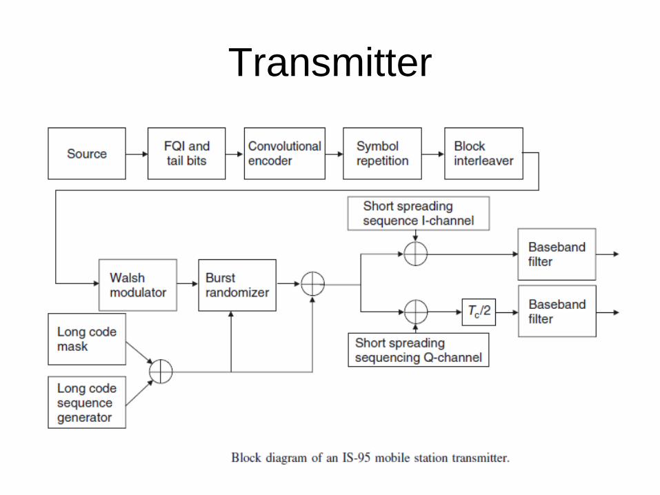
Transmitter

Spreading and Modulation
• The source data rate of 8.6 kbit/s or 13.3 kbit/s
to a chip rate of 1.2288 Mchip/s
• Encoding is usually done with standard
convolutional encoders.
• Spreading is done with “M-ary orthogonal
keying” or multiplication by spreading sequences

Channels

1. Pilot Channel
2. Power Control Subchannel
3. Synchronization Channel
4. Paging Channel
5. Traffic Channels
6. Access Channel

Pilot Signal
• Each BS sends out a pilot signal that the MS canuse for timing acquisition, channel estimation,and to help with the handover process.
• It is not power controlled
• It uses Walsh code 0 for transmission: this codeis the all-zero code.
• It has higher transmit power than traffic channels
Power Control Subchannel
• IS-95 strives to force each user to provide the same
power level at the base station receiver to avoid near-far
problem
• Mobiles use peak power of 200mW
• Since both the signal and interference are continually
varying, power control updates are sent by the base
station every 1.25 ms.

• Power control commands are sent to each subscriber unit
on the forward control subchannel which instruct the mobile
to raise or lower its transmitted power in 1 dB steps.
• If the received signal is low, a ‘0' is transmitted over the
power control subchannel, thereby instructing the mobile
station to increase its mean output power level.
• If the mobile's power is high, a ‘1’ is transmitted to indicate
that the mobile station should decrease its power level

Synchronization Channel
• The synchronization channel transmits information about
system details that are required for the MS to
synchronize itself to the network.
• The synchronization channel transmits data at 1.2 kbit/s.
• Synch message includes system ID (SID), network ID
(NID), the offset of the PN short code, the state of the
PN-long code, and the paging channel data rate (4.8/9.6
Kbps)
Paging Channel
• The paging channel transmits system and callinformation from the BS to the MS like…– Message to indicate incoming call
– System information and instructions
– Handoff thresholds
– Maximum number of unsuccessful access attempts
– Channel assignment messages.
– Acknowledgments to access requests.
Access Channel
• The access channel is a channel in the uplink that is
used for signaling by MSs
• Access channel messages include security messages
(authentication challenge response page response,
origination, and registration)
• A call initiated by the MS starts with a message on the
access channel

Traffic Channels
• Traffic channels are the channels on which the
voice data for each user are transmitted
• A number of control messages are also
transmitted on traffic channels

ORTHOGONAL FREQUENCY DIVISION MULTIPLEXING
• Orthogonal Frequency Division Multiplexing (OFDM)
is a modulation scheme suited for high-data-rate
transmission in delay-dispersive environments
• It converts a high-rate data stream into a number of
low-rate streams that are transmitted over parallel,
narrowband channels.
• OFDM is a combination of modulation and
multiplexing.

• Multiplexing generally refers to independent
signals.
• In OFDM the multiplexing is applied to
independent signals but these independent
signals are a sub-set of the one main signal.
• In OFDM the signal itself is first split into
independent channels, modulated by data and
then re-multiplexed to create the OFDM carrier

FDM Vs OFDM

• The main concept in OFDM is orthogonality ofthe sub-carriers.
• Since the carriers are all sine/cosine wave, weknow that area under one period of a sine or acosine wave is zero

Conditon for othogonalityf(x) . f(y) = 0
Multiplying 2 sine wavesf (t) = sinmwt sin nwt

• Hence we conclude that when we multiply a sinusoid offrequency n by a sinusoid of frequency m/n, the areaunder the product is zero.
• In general for all integers n and m, sinmx, cosmx, cos nx,sin nx are all orthogonal to each other. Thesefrequencies are called harmonics.
• A harmonic of a wave is a component frequency of thesignal that is an integer multiple of the fundamentalfrequency
• The orthogonality allows simultaneous transmission on alot of sub-carriers in a tight frequency space withoutinterference from each other


All three of these frequencies are harmonic to c1
• These carriers are orthogonal to each other,
when added together, they do not interfere with
each other

Let the first few bits are B(t)= 1, 1, -1, -1, 1, 1, 1, -1, 1, -1, -1, -1, -1, 1, -1, -1, -1, 1 .
. . . .

c1
Carrier 1 - We need to transmit 1, 1, 1 -1,-1,-1 , with a BPSK carrier of frequency 1 Hz. First three bits are 1 and last three -1
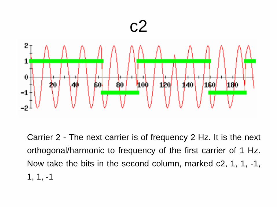
c2
Carrier 2 - The next carrier is of frequency 2 Hz. It is the nextorthogonal/harmonic to frequency of the first carrier of 1 Hz.Now take the bits in the second column, marked c2, 1, 1, -1,1, 1, -1
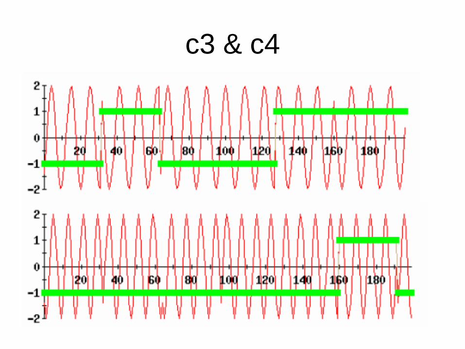
c3 & c4
![MC9214 DATA STRUCTURES/UNIT‐3 - chettinadtech.ac.inchettinadtech.ac.in/storage/11-11-12/11-11-12-08-46-22-1165... · ... (n) = [log2n] + 1 That is the running time for the worst](https://img.pdfslide.us/doc/110x75/5b0d26d87f8b9ab7658bfbca/mc9214-data-structuresunit3-n-log2n-1-that-is-the-running-time.jpg)