Embed Size (px)
Citation preview
A
Technical Report On
WIRELESS CHARGING OF MOBILEPHONES USING
MICROWAVES
Submitted In Partial Fulfillment For The Award Of Degree Of
B.TECH In
ELECTRONICS AND COMMUNICATION ENGINEERING
BY
1. SANAH MARYAM KHAN 07L51A0464
2. SAYEEDA SANA 07L51A0466
Department Of Electronics And Communication Engineering
SHADAN WOMEN’S COLLEGE OF ENGINEERING AND TECHNOLOGY
March 2011
1
CONTENTS:
1. ABSTRACT ……………………………………1-2
2. INTRODUCTION ……………………………..6-8
3. TRANSMITTER DESIGN ……………………9-11
4. RECIEVER DESIGN …………………………12-15
5. SENSOR CIRCUITARY ……………………...16-17
7. APPLICATIONS ………………………………….18
6. CONCLUSION …………………………………...19
8. REFERENCES ……………………………………20
2
ABSTRACT :
With mobile phones becoming a basic part of life, the recharging of mobile phone batteries has always been a problem. The mobile phones vary in their talk time and battery stand by according to their manufacturer and batteries. All these phones irrespective of their manufacturer and batteries have to be put to recharge after the battery has drained out.
The main objective of this current proposal is to make the recharging of the mobile phones independent of their manufacturer and battery make. In this paper a new proposal has been made so as to make the recharging of the mobile phones is done automatically as you talk in your mobile phone! This is done by use of microwaves.
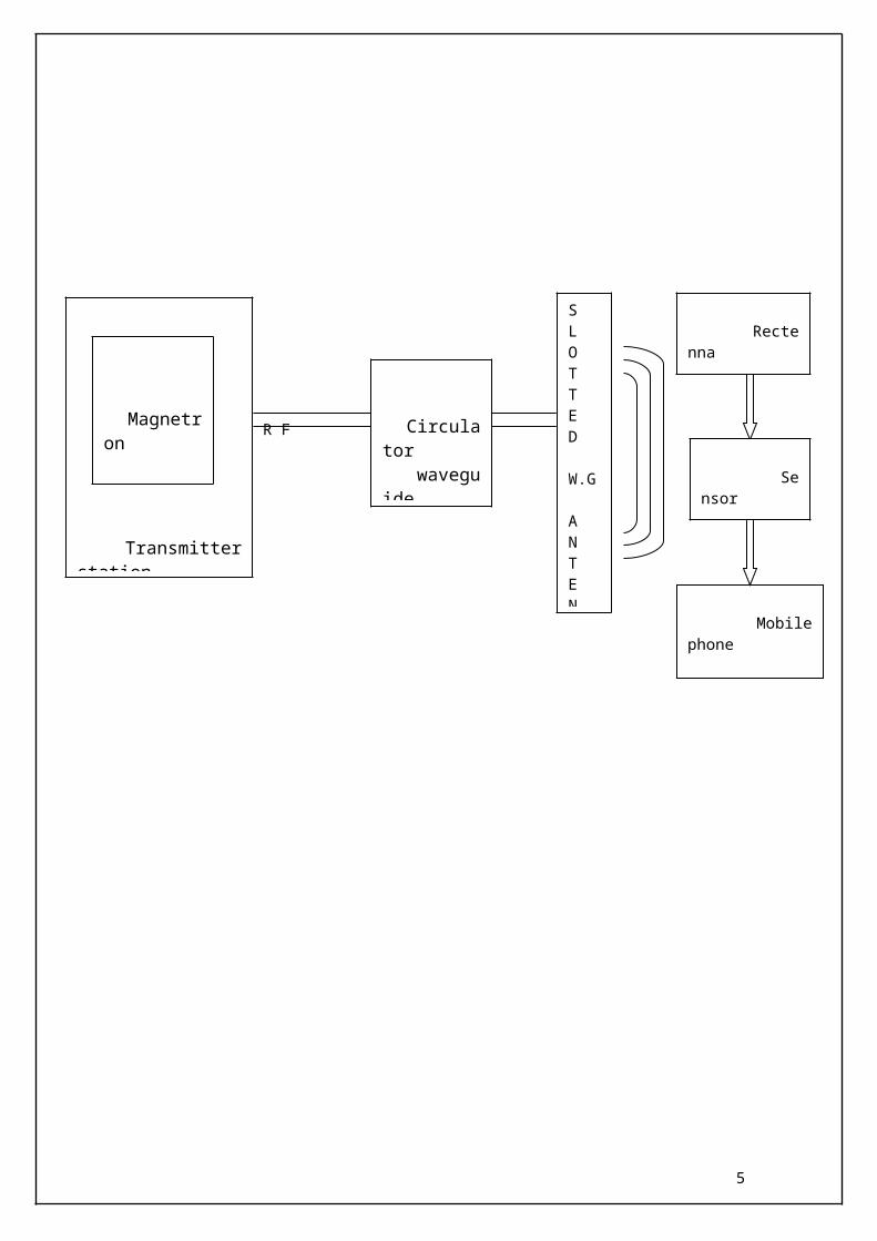
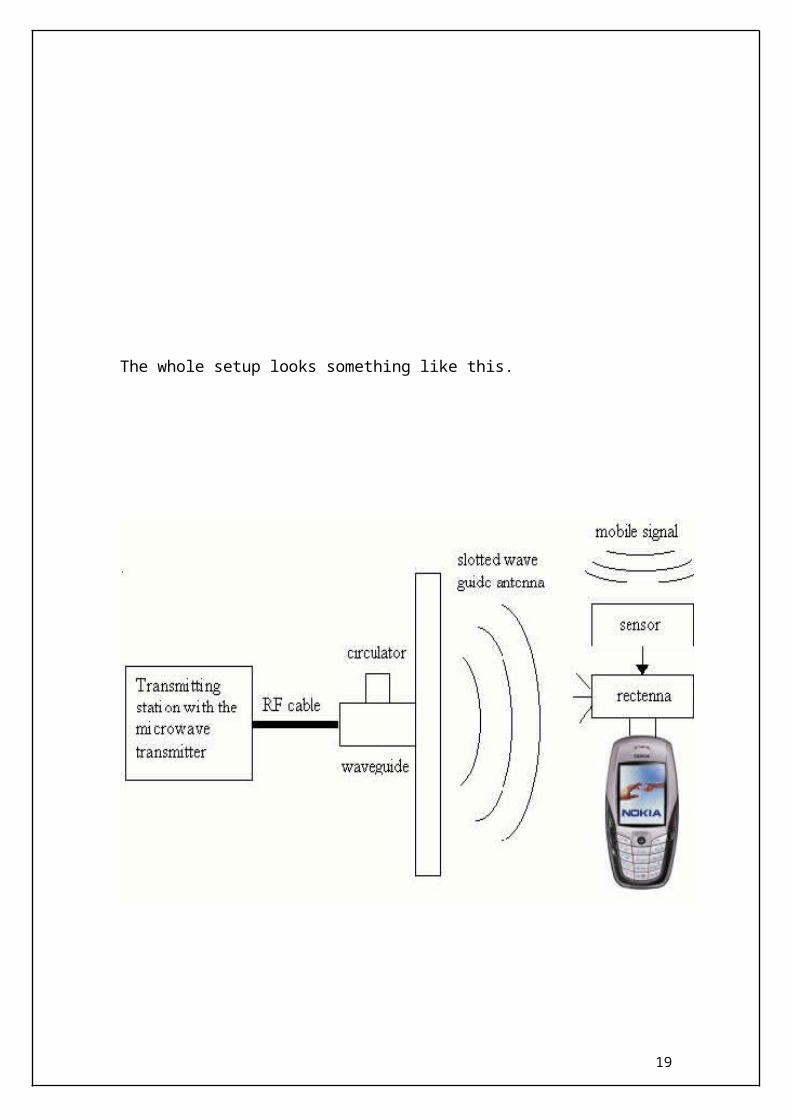
The microwave signal is transmitted from the transmitter along with the message signal using special kind of antennas called slotted wave guide antenna at a frequency is 2.45 GHz. There are minimal additions, which have to be made in the mobile handsets, which are the addition of a sensor, a Rectenna , and a filter.
With the above setup, the need for separate chargers for mobile phones is eliminated and makes charging universal. Thus the more you talk, the more is your mobile phone charged! With this proposal the manufacturers would be able to remove the talk time and battery stand by from their phone specifications
3
Mobile phone
R F
4
Transmitter station
Magnetron
Circulator waveguide
SLOTTED
W.G
ANTENNA
Rectenna
Sensor
5

6

INTRODUCTION
THE ELECTROMAGNETIC SPECTRUM
To start with, to know what a spectrum is: when white light is shone through a prism it is
separated out into all the colors of the rainbow; this is the visible spectrum. So white
light is a mixture of all colors. Black is NOT a color; it is what you get when all the light
is taken away. Some physicists pretend that light consists of tiny particles which they
call photons. They travel at the speed of light (what a surprise). The speed of light is
about 300,000,000 meters per second. When they hit something they might bounce off,
go right through or get absorbed. What happens depends a bit on how much energy they
have. If they bounce off something and then go into your eye you will "see" the thing
they have bounced off. Some things like glass and Perspex will let them go through;
these materials are transparent. Black objects absorb the photons so you should not be
able to see black things: you will have to think about this one. These poor old physicists
7
get a little bit confused when they try to explain why some photons go through a leaf,
some are reflected, and some are absorbed. They say that it is because they have
different amounts of energy. Other physicists pretend that light is made of waves. These
physicists measure the length of the waves and this helps them to explain what happens
when light hits leaves. The light with the longest wavelength (red) is absorbed by the
green stuff (chlorophyll) in the leaves. So is the light with the shortest wavelength (blue).
In between these two colors there is green light, this is allowed to pass right through or is
reflected. (Indigo and violet have shorter wavelengths than blue light.)
Well it is easy to explain some of the properties of light by
pretending that it is made of tiny particles called photons and it is easy to explain other
properties of light by pretending that it is some kind of wave. The visible spectrum is just
one small part of the electromagnetic spectrum. These electromagnetic waves are made
up of to two parts. The first part is an electric field. The second part is a magnetic field.
So that is why they are called electromagnetic waves. The two fields are at right angles
to each other.
THE MICROWAVE REGION
Microwave wavelengths range from approximately one millimeter (the thickness of a
pencil lead) to thirty centimeters (about twelve inches). In a microwave oven, the radio
waves generated are tuned to
frequencies that can be absorbed by the food . The food absorbs the energy and gets
warmer. The dish holding the food doesn't absorb a significant amount of energy and
stays much cooler. Microwaves are emitted from the Earth, from objects such as cars
and planes, and from the atmosphere. These microwaves can be detected to give
information, such as the temperature of the object that emitted the microwaves.
Microwaves have wavelengths that can be measured in centimeters!
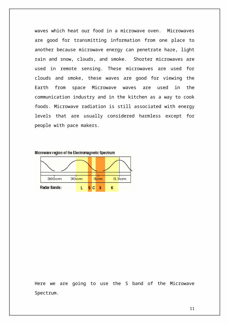
The longer microwaves, those closer to a foot in length, are the waves which heat our
food in a microwave oven. Microwaves are good for transmitting information from one
place to another because microwave energy can penetrate haze, light rain and snow,
8
clouds, and smoke. Shorter microwaves are used in remote sensing. These microwaves
are used for clouds and smoke, these waves are good for viewing the Earth from space
Microwave waves are used in the communication industry and in the kitchen as a way to
cook foods. Microwave radiation is still associated with energy levels that are usually
considered harmless except for people with pace makers.
Here we are going to use the S band of the Microwave Spectrum.
Designatio
n
Frequency
range
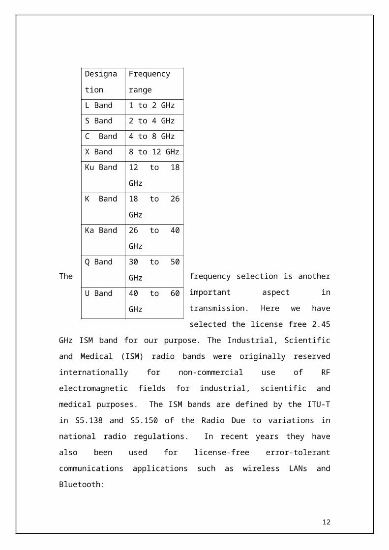
L Band 1 to 2 GHz
S Band 2 to 4 GHz
C Band 4 to 8 GHz
X Band 8 to 12 GHz
Ku Band 12 to 18 GHz
K Band 18 to 26 GHz
Ka Band 26 to 40 GHz
Q Band 30 to 50 GHz
U Band 40 to 60 GHz9
The frequency selection is another important aspect in transmission. Here we have
selected the license free 2.45 GHz ISM band for our purpose. The Industrial, Scientific
and Medical (ISM) radio bands were originally reserved internationally for non-
commercial use of RF electromagnetic fields for industrial, scientific and medical
purposes. The ISM bands are defined by the ITU-T in S5.138 and S5.150 of the Radio
Due to variations in national radio regulations. In recent years they have also been used
for license-free error-tolerant communications applications such as wireless LANs and
Bluetooth:
900 MHz band (33.3 cm) (also GSM communication in India)
2.45 GHz band (12.2 cm)
IEEE 802.11b wireless Ethernet also operates on the 2.45 GHz band.
TRANSMITTER DESIGN
MAGNETRON:
Magnetron is a high power microwave oscillator and it is used in microwave
oven and radar transmitter.
It is itself a special kind of vacum tube that has permanent magnet in its
constructions.
This magnet is setup to affect the path of travel of electrons that are in transit
from cathode to the plate.
Magnetron is capable to deliver more power than reflex klystron or gunn diode.
It is a high power oscillator and has high efficiency of 50% to 80%.
10
Magnetron is a device which produces microwave radiation of radar application
and microwaves.
Magnetron functions as self-excited microwave oscillator.
Crossed electron and magnetic fields are used to produce magnetron to produce
the high power output required in radar equipment.
These multi cavity devices are used in transmitters as pulsed or cw oscillators to
produce microwave radiation.
Disadvantage of magnetron is that it works only on fixed frequency
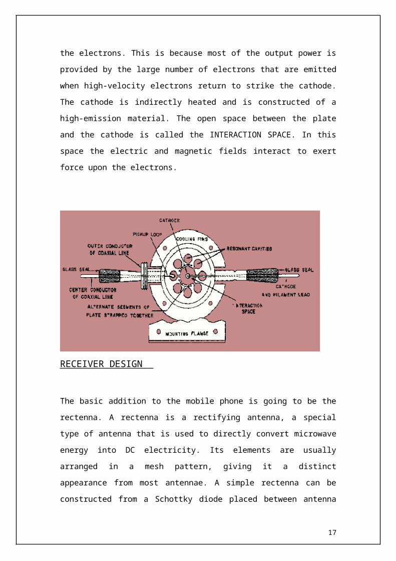
The MAGNETRON (A), is a self-contained microwave oscillator that operates
differently from the linear-beam tubes, such as the TWT and the klystron
11
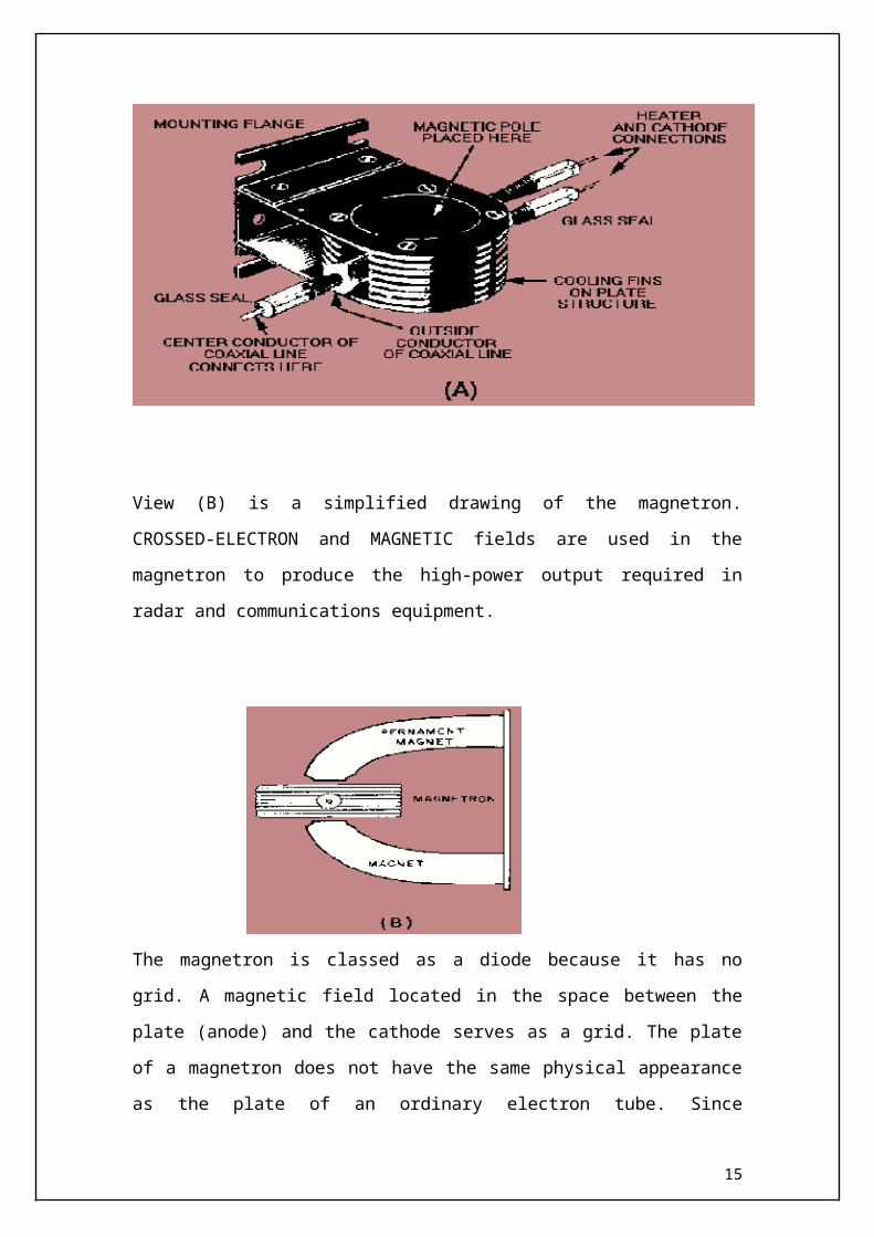
View (B) is a simplified drawing of the magnetron. CROSSED-ELECTRON and
MAGNETIC fields are used in the magnetron to produce the high-power output required
in radar and communications equipment.
The magnetron is classed as a diode because it has no grid. A magnetic field located in
the space between the plate (anode) and the cathode serves as a grid. The plate of a
magnetron does not have the same physical appearance as the plate of an ordinary
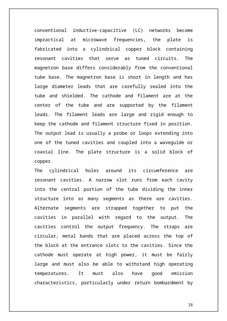
electron tube. Since conventional inductive-capacitive (LC) networks become
impractical at microwave frequencies, the plate is fabricated into a cylindrical copper
block containing resonant cavities that serve as tuned circuits. The magnetron base
differs considerably from the conventional tube base. The magnetron base is short in
length and has large diameter leads that are carefully sealed into the tube and shielded.
The cathode and filament are at the center of the tube and are supported by the filament
leads. The filament leads are large and rigid enough to keep the cathode and filament
structure fixed in position. The output lead is usually a probe or loops extending into one
of the tuned cavities and coupled into a waveguide or coaxial line. The plate structure is
a solid block of copper.
The cylindrical holes around its circumference are resonant cavities. A narrow slot runs
from each cavity into the central portion of the tube dividing the inner structure into as
many segments as there are cavities. Alternate segments are strapped together to put the
cavities in parallel with regard to the output. The cavities control the output frequency.
The straps are circular, metal bands that are placed across the top of the block at the
entrance slots to the cavities. Since the cathode must operate at high power, it must be
12
fairly large and must also be able to withstand high operating temperatures. It must also
have good emission characteristics, particularly under return bombardment by the
electrons. This is because most of the output power is provided by the large number of
electrons that are emitted when high-velocity electrons return to strike the cathode. The
cathode is indirectly heated and is constructed of a high-emission material. The open
space between the plate and the cathode is called the INTERACTION SPACE. In this
space the electric and magnetic fields interact to exert force upon the electrons.
RECEIVER DESIGN
The basic addition to the mobile phone is going to be the rectenna. A rectenna is a
rectifying antenna, a special type of antenna that is used to directly convert microwave
energy into DC electricity. Its elements are usually arranged in a mesh pattern, giving it a
distinct appearance from most antennae. A simple rectenna can be constructed from a
Schottky diode placed between antenna dipoles. The diode rectifies the current induced
in the antenna by the microwaves. Rectennae are highly efficient at converting
microwave energy to electricity. In laboratory environments, efficiencies above 90%
have been observed with regularity. Some experimentation has been done with inverse
rectennae, converting electricity into microwave energy, but efficiencies are much
lower--only in the area of 1%. With the advent of nanotechnology and MEMS the size of
these devices can be brought down to molecular level. It has been theorized that similar
devices, scaled down to the proportions used in nanotechnology, could be used to
13
convert light into electricity at much greater efficiencies than what is currently possible
with solar cells. This type of device is called an optical rectenna. Theoretically, high
efficiencies can be maintained as the device shrinks, but experiments funded by the
United States National Renewable energy Laboratory have so far only obtained roughly
1% efficiency while using infrared light. Another important part of our receiver circuitry
is a simple sensor. This is simply used to identify when the mobile phone user is talking.
As our main objective is to charge the mobile phone with the transmitted microwave
after rectifying it by the rectenna, the sensor plays an important role.
The whole setup looks something like this.
14
PROCESS OF RECTIFICATION
A rectenna is a rectifying antenna, an antenna used to convert microwaves into DC power. Being that an antenna refers to any type of device that converts electromagnetic waves into electricity or vice versa, a rectenna is simply a microwave antenna, in contrast to the ubiquitous radio and TV antennas. You've probably seen the word rectenna pop up in discussions of solar power satellites, or other power generation schemes involving microwave power transmission or beaming.
15
Rectennas are quite good at what they do: efficiencies above 90% are quite common. Inverse rectennas, which convert electricity into microwave beams, are only in the early stages of development, with efficiencies of only about 1%. This poses a problem for solar power satellite proposals.
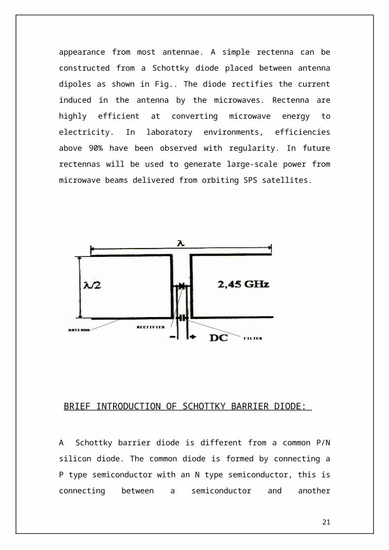
It rectifies received microwaves into DC current .A rectenna comprises of a mesh of
dipoles and diodes for absorbing microwave energy from a transmitter and converting it
into electric power. Its elements are usually arranged in a mesh pattern, giving it a
distinct appearance from most antennae. A simple rectenna can be constructed from a
Schottky diode placed between antenna dipoles as shown in Fig.. The diode rectifies the
current induced in the antenna by the microwaves. Rectenna are highly efficient at
converting microwave energy to electricity. In laboratory environments, efficiencies
above 90% have been observed with regularity. In future rectennas will be used to
generate large-scale power from microwave beams delivered from orbiting SPS
satellites.
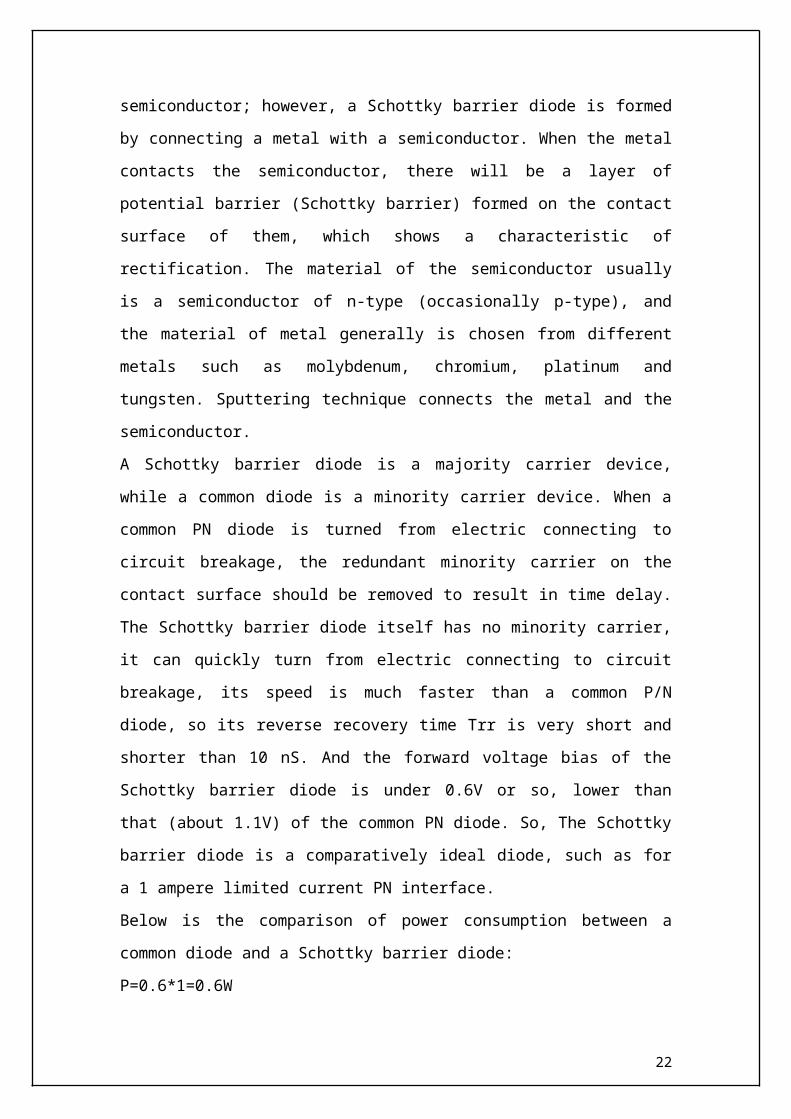
BRIEF INTRODUCTION OF SCHOTTKY BARRIER DIODE:
A Schottky barrier diode is different from a common P/N silicon diode. The common
diode is formed by connecting a P type semiconductor with an N type semiconductor,
this is connecting between a semiconductor and another semiconductor; however, a
Schottky barrier diode is formed by connecting a metal with a semiconductor. When the
16
metal contacts the semiconductor, there will be a layer of potential barrier (Schottky
barrier) formed on the contact surface of them, which shows a characteristic of
rectification. The material of the semiconductor usually is a semiconductor of n-type
(occasionally p-type), and the material of metal generally is chosen from different metals
such as molybdenum, chromium, platinum and tungsten. Sputtering technique connects
the metal and the semiconductor.
A Schottky barrier diode is a majority carrier device, while a common diode is a
minority carrier device. When a common PN diode is turned from electric connecting to
circuit breakage, the redundant minority carrier on the contact surface should be
removed to result in time delay. The Schottky barrier diode itself has no minority carrier,
it can quickly turn from electric connecting to circuit breakage, its speed is much faster
than a common P/N diode, so its reverse recovery time Trr is very short and shorter than
10 nS. And the forward voltage bias of the Schottky barrier diode is under 0.6V or so,
lower than that (about 1.1V) of the common PN diode. So, The Schottky barrier diode is
a comparatively ideal diode, such as for a 1 ampere limited current PN interface.
Below is the comparison of power consumption between a common diode and a
Schottky barrier diode:
P=0.6*1=0.6W
P=1.1*1=1.1W
It appears that the standards of efficiency differ widely. Besides, the PIV of the Schottky
barrier diode is generally far smaller than that of the PN diode; on the basis of the same
unit, the PIV of the Schottky barrier diode is probably 50V while the PIV of the PN
diode may be as high as 150V. Another advantage of the Schottky barrier diode is a very
low noise index that is very important for a communication receiver; its working scope
may reach20GHz.
SENSOR CIRCUITRY
The sensor circuitry is a simple circuit, which detects if the mobile phone receives any
message signal. This is required, as the phone has to be charged as long as the user is
talking. Thus a simple F to V converter would serve our purpose. In India the operating
frequency of the mobile phone operators is generally 900MHz or 1800MHz for the
17
GSM system for mobile communication. Thus the usage of simple F to V converters
would act as switches to trigger the rectenna circuit to on.
A simple yet powerful F to V converter is LM2907. Using LM2907 would greatly serve
our purpose. It acts as a switch for triggering the rectenna circuitry. The general block
diagram for the LM2907 is given below. Thus on the reception of the signal the sensor
circuitry directs the rectenna circuit to ON and the mobile phone begins to charge
using the microwave power.
A sensor is devised to sense the activities such as texting, calling, SMS and MMS, being carried out in a cell phone within a specified range.
It is an easy to use handy mobile device, sometimes also called as sniffer or pocket-size mobile transmission detector.
18
A number of phone sensor manufacturing companies have sprouted in the industry, each offering some or the other exceptional features in their products.
You can choose the one as per your own requirements.
A cell phone sensor can sense the presence of an activated cell phone within the range of around one and a half metres.
The cell phone sensor circuit has been designed to perfection so that it may be able to track the appearance of a mobile phone and all its activities, including SMS, video transmissions, incoming calls as well as outgoing calls.
The device is quiet capable to function properly even if the cell phone under surveillance is on silent mode.
As soon as the sensor senses the RF transmission signals from a phone located somewhere in its vicinity, it starts raising a beep alarm which continues till the signal transmission is not ceased.
APPLICATION:
Wireless charging of mobile phones using microwaves.
19
ADVANTAGE:
1. Use of separate chargers is eliminated.2. Electricity is saved.
3. The phone can be charged anywhere anytime.
CONCLUSION :
Thus this paper successfully demonstrates a novel method of using the power of the microwave to charge the mobile phones without the use of wired chargers. Thus this method provides great advantage to the mobile phone users to carry their phones anywhere even if the place is devoid of facilities for charging.
20
A novel use of the rectenna and a sensor in a mobile phone could provide a new dimension in the revelation of mobile phone. In this modern generation where we prefer the most efficient gadgets to serve our purposes, not even a slightly deviated device is acceptable. The highly accomplished cell phone sensor created by the topnotch manufacturers in the industry befit your needs exactly the best way and prove to be highly effective tools to combat security breach. Depending on the features they offer, these are available in different price ranges, you can buy the one that suits you the best.
REFERENCES:
1) www.google.com
21