Embed Size (px)
Citation preview
Wireless Cable Modem Gateway CGD24G User Manual
202-10389-02 May 2009v1.1
NETGEAR, Inc.350 East Plumeria DriveSan Jose, CA 95134 USA
© 2009 by NETGEAR, Inc. All rights reserved.
Technical SupportPlease refer to the support information card that shipped with your product. By registering your product at http://www.netgear.com/register, we can provide you with faster expert technical support and timely notices of product and software upgrades.NETGEAR, INC. Support InformationPhone: 1-888-NETGEAR, for US & Canada only. For other countries, see your Support information card.E-mail: [email protected] American NETGEAR website: http://www.netgear.com
TrademarksNETGEAR, the NETGEAR logo, ProSafe, and Auto Uplink are trademarks or registered trademarks of NETGEAR, Inc. Microsoft, Windows, Windows NT and Vista are registered trademarks of Microsoft Corporation.Other brand and product names are registered trademarks or trademarks of their respective holders.
Statement of ConditionsIn the interest of improving internal design, operational function, and/or reliability, NETGEAR reserves the right to make changes to the products described in this document without notice.NETGEAR does not assume any liability that may occur due to the use or application of the product(s) or circuit layout(s) described herein.
Certificate of the Manufacturer/ImporterIt is hereby certified that the CGD24G Wireless Cable Modem Gateway has been suppressed in accordance with the conditions set out in the BMPT-AmtsblVfg 243/1991 and Vfg 46/1992. The operation of some equipment (for example, test transmitters) in accordance with the regulations may, however, be subject to certain restrictions. Please refer to the notes in the operating instructions. The Federal Office for Telecommunications Approvals has been notified of the placing of this equipment on the market and has been granted the right to test the series for compliance with the regulations.
Bestätigung des Herstellers/ImporteursEs wird hiermit bestätigt, daß das CGD24G Wireless Cable Modem Gateway gemäß der im BMPT-AmtsblVfg 243/1991 und Vfg 46/1992 aufgeführten Bestimmungen entstört ist. Das vorschriftsmäßige Betreiben einiger Geräte (z.B. Testsender) kann jedoch gewissen Beschränkungen unterliegen. Lesen Sie dazu bitte die Anmerkungen in der Betriebsanleitung.Das Bundesamt für Zulassungen in der Telekommunikation wurde davon unterrichtet, daß dieses Gerät auf den Markt gebracht wurde und es ist berechtigt, die Serie auf die Erfüllung der Vorschriften hin zu überprüfen.
Voluntary Control Council for Interference (VCCI) StatementThis equipment is in the Class B category (information equipment to be used in a residential area or an adjacent area thereto) and conforms to the standards set by the Voluntary Control Council for Interference by Data Processing Equipment and Electronic Office Machines aimed at preventing radio interference in such residential areas. When used near a radio or TV receiver, it may become the cause of radio interference. Read instructions for correct handling.
ii
v1.1, May 2009
Regulatory Compliance InformationThis section includes user requirements for operating this product in accordance with National laws for usage of radio spectrum and operation of radio devices. Failure of the end-user to comply with the applicable requirements may result in unlawful operation and adverse action against the end-user by the applicable National regulatory authority.This product's firmware limits operation to only the channels allowed in a particular Region or Country. Therefore, all options described in this user's guide may not be available in your version of the product.
Europe – EU Declaration of Conformity
Marking by the above symbol indicates compliance with the Essential Requirements of the R&TTE Directive of the European Union (1999/5/EC). This equipment meets the following conformance standards:EN300 328, EN301 489-17, EN60950
Europe – Declaration of Conformity in Languages of the European Community
Cesky [Czech] NETGEAR Inc. tímto prohlašuje, že tento Radiolan je ve shode se základními požadavky a dalšími príslušnými ustanoveními smernice 1999/5/ES.
Dansk [Danish]
Undertegnede NETGEAR Inc. erklærer herved, at følgende udstyr Radiolan overholder de væsentlige krav og øvrige relevante krav i direktiv 1999/5/EF.
Deutsch [German]
Hiermit erklärt NETGEAR Inc., dass sich das Gerät Radiolan in Übereinstimmung mit den grundlegenden Anforderungen und den übrigen einschlägigen Bestimmungen der Richtlinie 1999/5/EG befindet.
Eesti [Estonian]
Käesolevaga kinnitab NETGEAR Inc. seadme Radiolan vastavust direktiivi 1999/5/EÜ põhinõuetele ja nimetatud direktiivist tulenevatele teistele asjakohastele sätetele.
English Hereby, NETGEAR Inc., declares that this Radiolan is in compliance with the essential requirements and other relevant provisions of Directive 1999/5/EC.
Español [Spanish]
Por medio de la presente NETGEAR Inc. declara que el Radiolan cumple con los requisitos esenciales y cualesquiera otras disposiciones aplicables o exigibles de la Directiva 1999/5/CE.
Ελληνική [Greek]
ΜΕ ΤΗΝ ΠΑΡΟΥΣΑ NETGEAR Inc. ΔΗΛΩΝΕΙ ΟΤΙ Radiolan ΣΥΜΜΟΡΦΩΝΕΤΑΙ ΠΡΟΣ ΤΙΣ ΟΥΣΙΩΔΕΙΣ ΑΠΑΙΤΗΣΕΙΣ ΚΑΙ ΤΙΣ ΛΟΙΠΕΣ ΣΧΕΤΙΚΕΣ ΔΙΑΤΑΞΕΙΣ ΤΗΣ ΟΔΗΓΙΑΣ 1999/5/ΕΚ.
Français [French]
Par la présente NETGEAR Inc. déclare que l'appareil Radiolan est conforme aux exigences essentielles et aux autres dispositions pertinentes de la directive 1999/5/CE.
Italiano [Italian] Con la presente NETGEAR Inc. dichiara che questo Radiolan è conforme ai requisiti essenziali ed alle altre disposizioni pertinenti stabilite dalla direttiva 1999/5/CE.
Latviski [Latvian]
Ar šo NETGEAR Inc. deklarē, ka Radiolan atbilst Direktīvas 1999/5/EK būtiskajām prasībām un citiem ar to saistītajiem noteikumiem.
v1.1, May 2009
iii
FCC Requirements for Operation in the United States
FCC Information to User
This product does not contain any user serviceable components and is to be used with approved antennas only. Any product changes or modifications will invalidate all applicable regulatory certifications and approvals
FCC Guidelines for Human Exposure
This equipment complies with FCC radiation exposure limits set forth for an uncontrolled environment. This equipment should be installed and operated with minimum distance of 20 cm between the radiator and your body. This transmitter must not be co-located or operating in conjunction with any other antenna or transmitter.
Lietuvių [Lithuanian]
Šiuo NETGEAR Inc. deklaruoja, kad šis Radiolan atitinka esminius reikalavimus ir kitas 1999/5/EB Direktyvos nuostatas.
Nederlands [Dutch]
Hierbij verklaart NETGEAR Inc. dat het toestel Radiolan in overeenstemming is met de essentiële eisen en de andere relevante bepalingen van richtlijn 1999/5/EG.
Malti [Maltese] Hawnhekk, NETGEAR Inc., jiddikjara li dan Radiolan jikkonforma mal-htigijiet essenzjali u ma provvedimenti ohrajn relevanti li hemm fid-Dirrettiva 1999/5/EC.
Magyar [Hungarian]
Alulírott, NETGEAR Inc. nyilatkozom, hogy a Radiolan megfelel a vonatkozó alapvetõ követelményeknek és az 1999/5/EC irányelv egyéb elõírásainak.
Polski [Polish] Niniejszym NETGEAR Inc. oświadcza, że Radiolan jest zgodny z zasadniczymi wymogami oraz pozostałymi stosownymi postanowieniami Dyrektywy 1999/5/EC.
Português [Portuguese]
NETGEAR Inc. declara que este Radiolan está conforme com os requisitos essenciais e outras disposições da Directiva 1999/5/CE.
Slovensko [Slovenian]
NETGEAR Inc. izjavlja, da je ta Radiolan v skladu z bistvenimi zahtevami in ostalimi relevantnimi določili direktive 1999/5/ES.
Slovensky [Slovak]
NETGEAR Inc. týmto vyhlasuje, _e Radiolan spĺňa základné po_iadavky a všetky príslušné ustanovenia Smernice 1999/5/ES.
Suomi [Finnish]
NETGEAR Inc. vakuuttaa täten että Radiolan tyyppinen laite on direktiivin 1999/5/EY oleellisten vaatimusten ja sitä koskevien direktiivin muiden ehtojen mukainen.
Svenska [Swedish]
Härmed intygar NETGEAR Inc. att denna Radiolan står I överensstämmelse med de väsentliga egenskapskrav och övriga relevanta bestämmelser som framgår av direktiv 1999/5/EG.
Íslenska [Icelandic]
Hér með lýsir NETGEAR Inc. yfir því að Radiolan er í samræmi við grunnkröfur og aðrar kröfur, sem gerðar eru í tilskipun 1999/5/EC.
Norsk [Norwegian]
NETGEAR Inc. erklærer herved at utstyret Radiolan er i samsvar med de grunnleggende krav og øvrige relevante krav i direktiv 1999/5/EF.
v1.1, May 2009
iv
FCC Declaration Of Conformity
We NETGEAR, Inc., 4500 Great America Parkway, Santa Clara, CA 95054, declare under our sole responsibility that the model CGD24G Wireless Cable Modem Gateway complies with Part 15 of FCC Rules. Operation is subject to the following two conditions:• This device may not cause harmful interference, and• This device must accept any interference received, including interference that may cause undesired operation.
FCC Radio Frequency Interference Warnings & Instructions
This equipment has been tested and found to comply with the limits for a Class B digital device, pursuant to Part 15 of the FCC Rules. These limits are designed to provide reasonable protection against harmful interference in a residential installation. This equipment uses and can radiate radio frequency energy and, if not installed and used in accordance with the instructions, may cause harmful interference to radio communications. However, there is no guarantee that interference will not occur in a particular installation. If this equipment does cause harmful interference to radio or television reception, which can be determined by turning the equipment off and on, the user is encouraged to try to correct the interference by one or more of the following methods:• Reorient or relocate the receiving antenna• Increase the separation between the equipment and the receiver• Connect the equipment into an electrical outlet on a circuit different from that which the radio receiver is connected• Consult the dealer or an experienced radio/TV technician for help.
Modifications made to the product, unless expressly approved by NETGEAR, Inc., could void the user's right to operate the equipment.
Canadian Department of Communications Radio Interference RegulationsThis digital apparatus (CGD24G Wireless Cable Modem Gateway) does not exceed the Class B limits for radio-noise emissions from digital apparatus as set out in the Radio Interference Regulations of the Canadian Department of Communications.Canada ID: 4054A-WG111
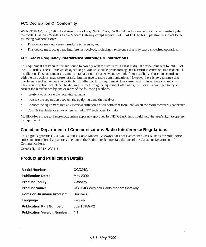
Product and Publication Details
Model Number: CGD24G
Publication Date: May 2009
Product Family: Gateway
Product Name: CGD24G Wireless Cable Modem Gateway
Home or Business Product: Business
Language: English
Publication Part Number: 202-10389-02
Publication Version Number: 1.1
v1.1, May 2009
v

v1.1, May 2009
vi
Contents
Wireless Cable Modem Gateway CGD24G User ManualAbout This Manual
Conventions, Formats and Scope .................................................................................... xiHow to Use This Manual ..................................................................................................xiiHow to Print this Manual ...................................................................................................xiiRevision History ...............................................................................................................xiv
Chapter 1 Connecting the Gateway to the Internet
Package Contents ..........................................................................................................1-1Router Front Panel ...................................................................................................1-2Router Rear Panel ...................................................................................................1-3Router Side Panel ....................................................................................................1-3
What You Need Before You Begin ..................................................................................1-4Hardware Requirements ..........................................................................................1-4LAN Configuration Requirements ............................................................................1-4Internet Configuration Requirements .......................................................................1-4
Connecting the CGD24G Gateway ................................................................................1-5Installation ................................................................................................................1-5
Configuring the Basic Settings .......................................................................................1-9Chapter 2 Wireless Configuration
Planning Your Wireless Network ....................................................................................2-1Wireless Placement and Range Guidelines .............................................................2-2Wireless Security Options ........................................................................................2-3
Manually Configuring Your Wireless Settings and Security ............................................2-3Configuring WEP (Wired Equivalent Privacy) Wireless Security .............................2-6Configuring WPA or WPA2 Wireless Security ..........................................................2-8
Using Push 'N' Connect (WPS) to Configure Your Wireless Network and Security .....2-10Using a WPS Button to Add a WPS Client ............................................................. 2-11
vii
v1.1, May 2009
Wireless Cable Modem Gateway CGD24G User Manual
Using a PIN Entry to Add a WPS Client .................................................................2-12Connecting Additional Wireless Client Devices ............................................................2-14
Adding Just WPS Clients .......................................................................................2-14Adding Both WPS and Non-WPS Clients ..............................................................2-14
Wireless Guest Networks .............................................................................................2-15How to Configure a Wireless Guest Network .........................................................2-15How to Configure Wireless Security for a Wireless Guest Network .......................2-17
Configuring Wi-Fi Multimedia .......................................................................................2-19Turning on Access Control to Restrict Access by MAC Address ..................................2-21
Chapter 3 Content Filtering and Firewall Rules
Configuring Logs ............................................................................................................3-1Blocking Keywords, Sites, and Services ........................................................................3-2
Blocking Keywords and Domains .............................................................................3-2Blocking Services .....................................................................................................3-4
Firewall Rules—Port Forwarding and Port Blocking .......................................................3-5Configuring Port Forwarding ....................................................................................3-6Configuring Port Blocking .........................................................................................3-8
Chapter 4 Managing Your Network
Viewing the Gateway Status ...........................................................................................4-1Viewing the Connection Status .......................................................................................4-3Changing the Built-In Password .....................................................................................4-4
Resetting to Factory Default Settings .......................................................................4-5Backing Up and Restoring Your Settings ........................................................................4-5Viewing the Event Log ....................................................................................................4-6Running Diagnostic Utilities ............................................................................................4-7
Chapter 5 Customizing Your Network
Configuring Dynamic DNS ..............................................................................................5-1Configuring RIP ..............................................................................................................5-3Restricting Access by MAC Address ..............................................................................5-5Configuring Port Triggering .............................................................................................5-7Setting Up a DMZ Host ...................................................................................................5-9LAN IP Settings ............................................................................................................5-10
viii Contents
v1.1, May 2009
Wireless Cable Modem Gateway CGD24G User Manual
Reserving an IP Address for DHCP Use ................................................................ 5-11Enabling Remote Management ....................................................................................5-12
Reverting to Factory Default Setting ......................................................................5-13Managing the URL to Connect to The Gateway ....................................................5-14
Configuring Universal Plug and Play (UPnP) ...............................................................5-14Chapter 5 Troubleshooting
Basic Functions ..............................................................................................................5-1Using LEDs to Troubleshoot ....................................................................................5-2
Connecting to the Gateway’s Main Menu .......................................................................5-3Troubleshooting the ISP Connection ..............................................................................5-4Troubleshooting a TCP/IP Network Using a Ping Utility .................................................5-4
Testing the LAN Path to Your Gateway ....................................................................5-4Testing the Path from Your PC to a Remote Device ................................................5-5
Appendix A Technical Specifications and Factory Default Settings
Technical Specifications ................................................................................................. A-1Factory Default Settings ................................................................................................ A-2
Appendix B Related DocumentsIndex
Contents ix
v1.1, May 2009
Wireless Cable Modem Gateway CGD24G User Manual
x Contents
v1.1, May 2009
About This Manual
The NETGEAR® Wireless Cable Modem Gateway CGD24G User Manual describes how to install, configure and troubleshoot the CGD24G Wireless Cable Modem Gateway. The information in this manual is intended for readers with intermediate computer and Internet skills.
Conventions, Formats and Scope
The conventions, formats, and scope of this manual are described in the following paragraphs:
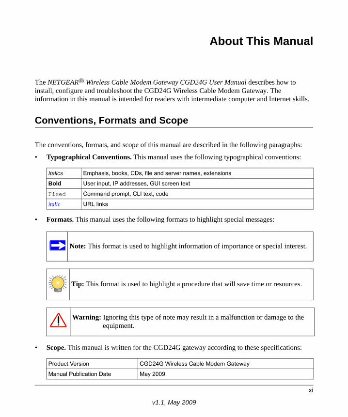
• Typographical Conventions. This manual uses the following typographical conventions:
• Formats. This manual uses the following formats to highlight special messages:
• Scope. This manual is written for the CGD24G gateway according to these specifications:
Italics Emphasis, books, CDs, file and server names, extensions
Bold User input, IP addresses, GUI screen text
Fixed Command prompt, CLI text, code
italic URL links
Note: This format is used to highlight information of importance or special interest.
Tip: This format is used to highlight a procedure that will save time or resources.
Warning: Ignoring this type of note may result in a malfunction or damage to the equipment.
Product Version CGD24G Wireless Cable Modem Gateway
Manual Publication Date May 2009
xi
v1.1, May 2009
Wireless Cable Modem Gateway CGD24G User Manual
For more information about network, Internet, firewall, and VPN technologies, see the links to the NETGEAR website in Appendix B, “Related Documents.
How to Use This Manual
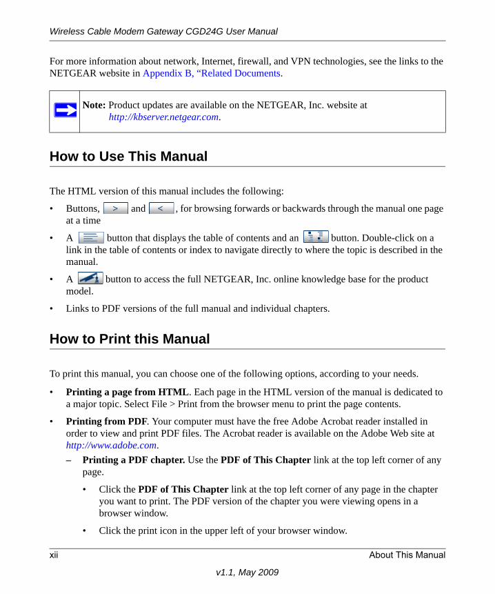
The HTML version of this manual includes the following:
• Buttons, and , for browsing forwards or backwards through the manual one page at a time
• A button that displays the table of contents and an button. Double-click on a link in the table of contents or index to navigate directly to where the topic is described in the manual.
• A button to access the full NETGEAR, Inc. online knowledge base for the product model.
• Links to PDF versions of the full manual and individual chapters.
How to Print this Manual
To print this manual, you can choose one of the following options, according to your needs.
• Printing a page from HTML. Each page in the HTML version of the manual is dedicated to a major topic. Select File > Print from the browser menu to print the page contents.
• Printing from PDF. Your computer must have the free Adobe Acrobat reader installed in order to view and print PDF files. The Acrobat reader is available on the Adobe Web site at http://www.adobe.com.– Printing a PDF chapter. Use the PDF of This Chapter link at the top left corner of any
page.
• Click the PDF of This Chapter link at the top left corner of any page in the chapter you want to print. The PDF version of the chapter you were viewing opens in a browser window.
• Click the print icon in the upper left of your browser window.
Note: Product updates are available on the NETGEAR, Inc. website athttp://kbserver.netgear.com.
xii About This Manual
v1.1, May 2009
Wireless Cable Modem Gateway CGD24G User Manual
– Printing a PDF version of the complete manual. Use the Complete PDF Manual link at the top left corner of any page.
• Click the Complete PDF Manual link at the top left corner of any page in the manual. The PDF version of the complete manual opens in a browser window.
– Click the print icon in the upper left corner of your browser window.
• Printing the Full Manual.
Use the Complete PDF Manual link at the top left of any page.
– Click the Complete PDF Manual link at the top left of any page in the manual. The PDF version of the complete manual opens in a browser window.
– Click the print icon in the upper left of the window.
Revision History
NETGEAR, Inc. is constantly searching for ways to improve its products and documentation. The following table indicates any changes that might have been made since the CGD24G gateway was introduced.
Tip: If your printer supports printing two pages on a single sheet of paper, you can save paper and printer ink by selecting this feature.
Tip: If your printer supports printing two pages on a single sheet of paper, you can save paper and printer ink by selecting this feature.
Part Number Version Number Date Description
202-10389-01 v1.0 June 2008 First publication.
About This Manual xiii
v1.1, May 2009
Wireless Cable Modem Gateway CGD24G User Manual
202-10389-02 v1.0 November 2008 • Added information about grounding the cable distribution system.
• Added information about attaching brackets to the CGD24G gateway, allowing it to be placed vertically.
• Made minor changes and corrections.
02-10389-02 v1.1 May 2009 • Added MSO login.• Updated LED behavior and screen shots .• Removed references to static IP and RIP
Setup features.
Part Number Version Number Date Description
xiv About This Manual
v1.1, May 2009
Chapter 1Connecting the Gateway to the Internet
This chapter describes how to set up the CGD24G gateway on your Local Area Network (LAN), connect to the Internet, and perform basic configuration.
Package Contents
The product package should contain the following items:• CGD24G Wireless Cable Modem Gateway• AC power adapter• Category 5 (CAT5) Ethernet cable• USB cable• Two brackets
If any of the parts are incorrect, missing, or damaged, contact your NETGEAR dealer. Keep the carton, including the original packing materials, in case you need to return the product for repair.
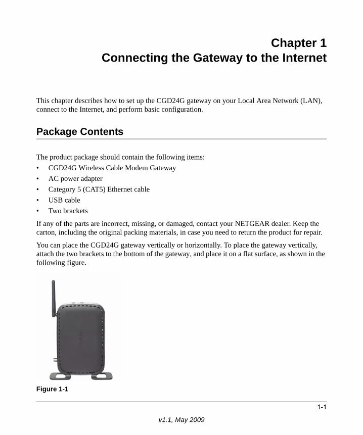
You can place the CGD24G gateway vertically or horizontally. To place the gateway vertically, attach the two brackets to the bottom of the gateway, and place it on a flat surface, as shown in the following figure.
Figure 1-1
1-1
v1.1, May 2009
Wireless Cable Modem Gateway CGD24G User Manual
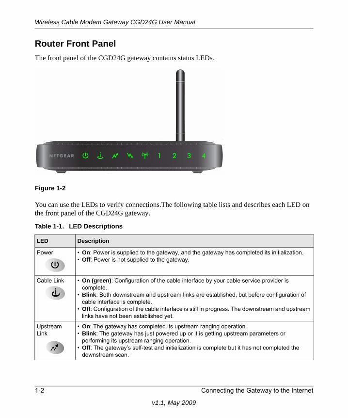
Router Front PanelThe front panel of the CGD24G gateway contains status LEDs.
You can use the LEDs to verify connections.The following table lists and describes each LED on the front panel of the CGD24G gateway.
Figure 1-2
Table 1-1. LED Descriptions
LED Description
Power • On: Power is supplied to the gateway, and the gateway has completed its initialization.• Off: Power is not supplied to the gateway.
Cable Link • On (green): Configuration of the cable interface by your cable service provider is complete.
• Blink: Both downstream and upstream links are established, but before configuration of cable interface is complete.
• Off: Configuration of the cable interface is still in progress. The downstream and upstream links have not been established yet.
Upstream Link
• On: The gateway has completed its upstream ranging operation.• Blink: The gateway has just powered up or it is getting upstream parameters or
performing its upstream ranging operation.• Off: The gateway’s self-test and initialization is complete but it has not completed the
downstream scan.
1-2 Connecting the Gateway to the Internet
v1.1, May 2009
Wireless Cable Modem Gateway CGD24G User Manual
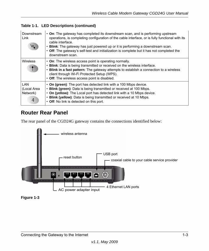
Router Rear PanelThe rear panel of the CGD24G gateway contains the connections identified below:
Downstream Link
• On: The gateway has completed its downstream scan, and is performing upstream operations, is completing configuration of the cable interface, or is fully functional with its cable interface.
• Blink: The gateway has just powered up or it is performing a downstream scan.• Off: The gateway’s self-test and initialization is complete but it has not completed the
downstream scan.
Wireless • On: The wireless access point is operating normally.• Blink: Data is being transmitted or received on the wireless interface.• Blink in a fast pattern: The gateway attempts to establish a connection to a wireless
client through Wi-Fi Protected Setup (WPS).• Off: The wireless access point is disabled.
LAN(Local Area Network)
• On (green): The port has detected link with a 100 Mbps device.• Blink (green): Data is being transmitted or received at 100 Mbps.• On (yellow): The Local port has detected link with a 10 Mbps device.• Blink (yellow): Data is being transmitted or received at 10 Mbps.• Off: No link is detected on this port.
Figure 1-3
Table 1-1. LED Descriptions (continued)
AC power adapter input
wireless antenna
reset buttonUSB port
4 Ethernet LAN ports
coaxial cable to your cable service provider
Connecting the Gateway to the Internet 1-3
v1.1, May 2009
Wireless Cable Modem Gateway CGD24G User Manual
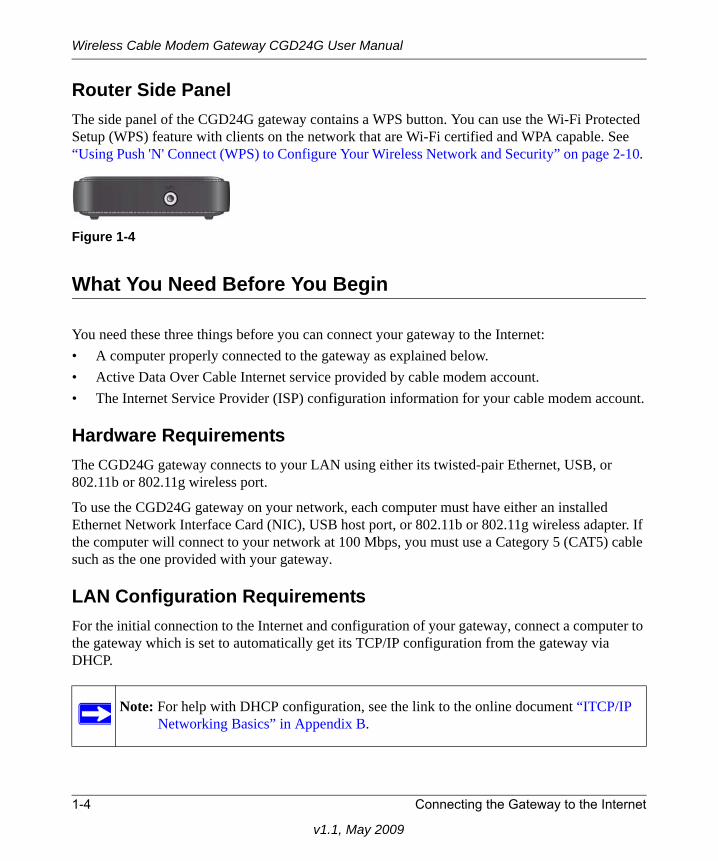
Router Side PanelThe side panel of the CGD24G gateway contains a WPS button. You can use the Wi-Fi Protected Setup (WPS) feature with clients on the network that are Wi-Fi certified and WPA capable. See “Using Push 'N' Connect (WPS) to Configure Your Wireless Network and Security” on page 2-10.
What You Need Before You Begin
You need these three things before you can connect your gateway to the Internet:• A computer properly connected to the gateway as explained below.• Active Data Over Cable Internet service provided by cable modem account.• The Internet Service Provider (ISP) configuration information for your cable modem account.
Hardware RequirementsThe CGD24G gateway connects to your LAN using either its twisted-pair Ethernet, USB, or 802.11b or 802.11g wireless port.
To use the CGD24G gateway on your network, each computer must have either an installed Ethernet Network Interface Card (NIC), USB host port, or 802.11b or 802.11g wireless adapter. If the computer will connect to your network at 100 Mbps, you must use a Category 5 (CAT5) cable such as the one provided with your gateway.
LAN Configuration RequirementsFor the initial connection to the Internet and configuration of your gateway, connect a computer to the gateway which is set to automatically get its TCP/IP configuration from the gateway via DHCP.
Figure 1-4
Note: For help with DHCP configuration, see the link to the online document “ITCP/IP Networking Basics” in Appendix B.
1-4 Connecting the Gateway to the Internet
v1.1, May 2009
Wireless Cable Modem Gateway CGD24G User Manual
Connecting the Gateway
Follow these steps to install your gateway:
1. Connect the gateway.
a. Turn off your computer.
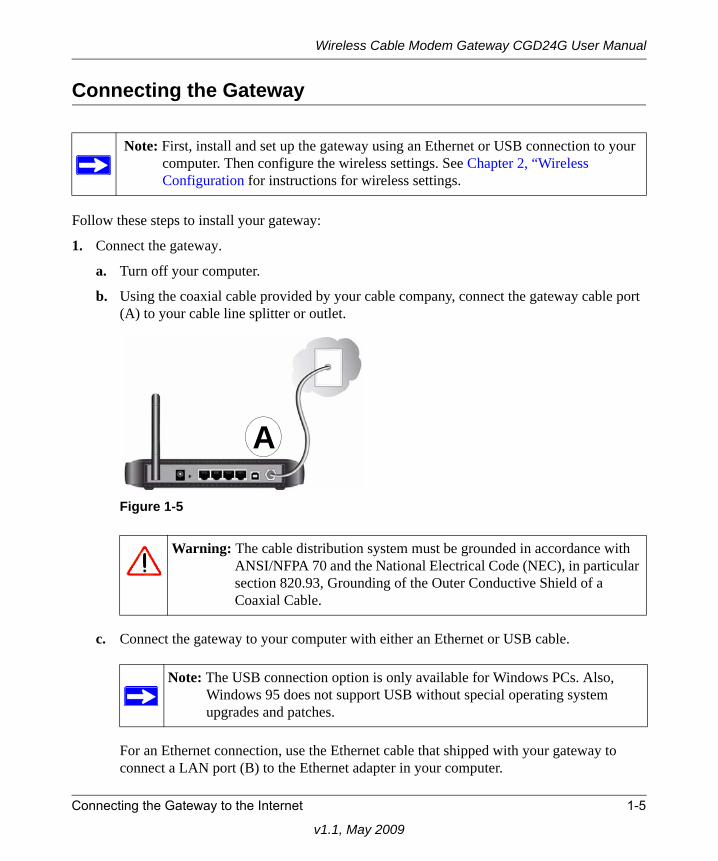
b. Using the coaxial cable provided by your cable company, connect the gateway cable port (A) to your cable line splitter or outlet.
c. Connect the gateway to your computer with either an Ethernet or USB cable.
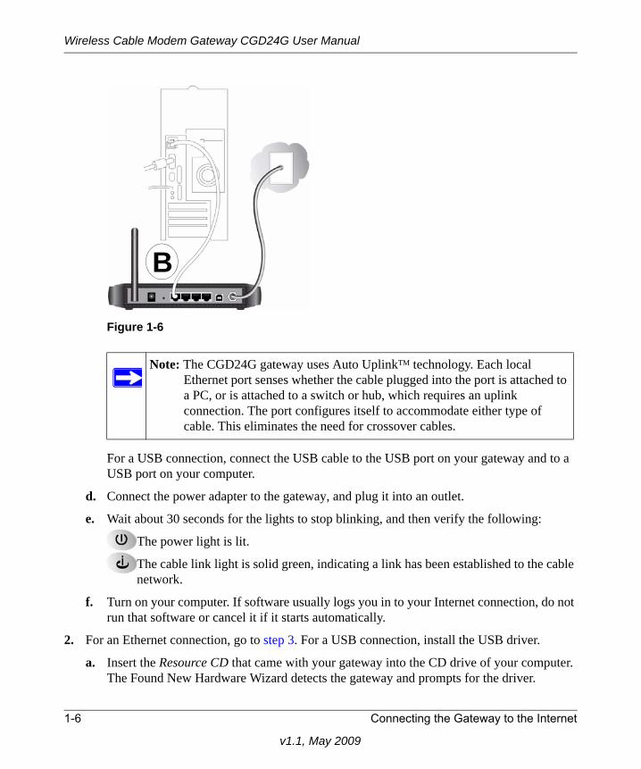
For an Ethernet connection, use the Ethernet cable that shipped with your gateway to connect a LAN port (B) to the Ethernet adapter in your computer.
Note: First, install and set up the gateway using an Ethernet or USB connection to your computer. Then configure the wireless settings. See Chapter 2, “Wireless Configuration for instructions for wireless settings.
Figure 1-5
Warning: The cable distribution system must be grounded in accordance with ANSI/NFPA 70 and the National Electrical Code (NEC), in particular section 820.93, Grounding of the Outer Conductive Shield of a Coaxial Cable.
Note: The USB connection option is only available for Windows PCs. Also, Windows 95 does not support USB without special operating system upgrades and patches.
A
Connecting the Gateway to the Internet 1-5
v1.1, May 2009
Wireless Cable Modem Gateway CGD24G User Manual
For a USB connection, connect the USB cable to the USB port on your gateway and to a USB port on your computer.
d. Connect the power adapter to the gateway, and plug it into an outlet.
e. Wait about 30 seconds for the lights to stop blinking, and then verify the following:
The power light is lit.
The cable link light is solid green, indicating a link has been established to the cable network.
f. Turn on your computer. If software usually logs you in to your Internet connection, do not run that software or cancel it if it starts automatically.
2. For an Ethernet connection, go to step 3. For a USB connection, install the USB driver.
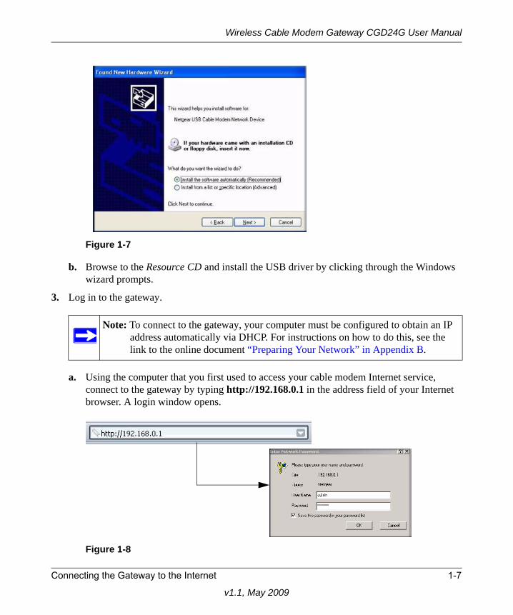
a. Insert the Resource CD that came with your gateway into the CD drive of your computer. The Found New Hardware Wizard detects the gateway and prompts for the driver.
Figure 1-6
Note: The CGD24G gateway uses Auto UplinkTM technology. Each local Ethernet port senses whether the cable plugged into the port is attached to a PC, or is attached to a switch or hub, which requires an uplink connection. The port configures itself to accommodate either type of cable. This eliminates the need for crossover cables.
B
1-6 Connecting the Gateway to the Internet
v1.1, May 2009
Wireless Cable Modem Gateway CGD24G User Manual
b. Browse to the Resource CD and install the USB driver by clicking through the Windows wizard prompts.
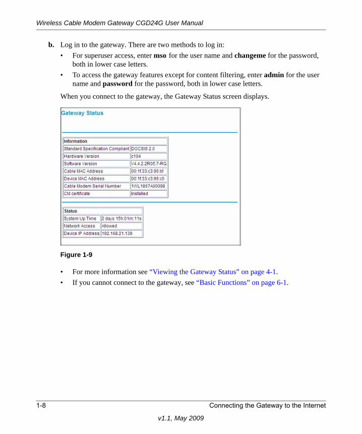
3. Log in to the gateway.
a. Using the computer that you first used to access your cable modem Internet service, connect to the gateway by typing http://192.168.0.1 in the address field of your Internet browser. A login window opens.
Figure 1-7
Note: To connect to the gateway, your computer must be configured to obtain an IP address automatically via DHCP. For instructions on how to do this, see the link to the online document “Preparing Your Network” in Appendix B.
Figure 1-8
Connecting the Gateway to the Internet 1-7
v1.1, May 2009
Wireless Cable Modem Gateway CGD24G User Manual
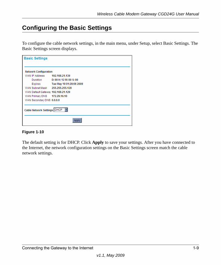
b. Log in to the gateway. There are two methods to log in:• For superuser access, enter mso for the user name and changeme for the password,
both in lower case letters.• To access the gateway features except for content filtering, enter admin for the user
name and password for the password, both in lower case letters.
When you connect to the gateway, the Gateway Status screen displays.
• For more information see “Viewing the Gateway Status” on page 4-1. • If you cannot connect to the gateway, see “Basic Functions” on page 6-1.
Figure 1-9
1-8 Connecting the Gateway to the Internet
v1.1, May 2009
Wireless Cable Modem Gateway CGD24G User Manual
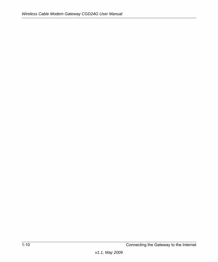
Configuring the Basic Settings
To configure the cable network settings, in the main menu, under Setup, select Basic Settings. The Basic Settings screen displays.
The default setting is for DHCP. Click Apply to save your settings. After you have connected to the Internet, the network configuration settings on the Basic Settings screen match the cable network settings.
Figure 1-10
Connecting the Gateway to the Internet 1-9
v1.1, May 2009
Wireless Cable Modem Gateway CGD24G User Manual
1-10 Connecting the Gateway to the Internet
v1.1, May 2009
Chapter 2Wireless Configuration
For a wireless connection, the SSID, also called the wireless network name, and the wireless security setting must be the same for the gateway and wireless computers or wireless adapters. NETGEAR strongly recommends that you use wireless security. This chapter includes:
• “Planning Your Wireless Network” on this page• “Manually Configuring Your Wireless Settings and Security” on page 2-3• “Using Push 'N' Connect (WPS) to Configure Your Wireless Network and Security” on
page 2-10• “Connecting Additional Wireless Client Devices” on page 2-13• “Wireless Guest Networks” on page 2-14• “Configuring Wi-Fi Multimedia” on page 2-18• “Turning on Access Control to Restrict Access by MAC Address” on page 2-19
Planning Your Wireless Network
For compliance and compatibility between similar products in your area, the operating channel and region must be set correctly.
To configure the wireless network, you can either specify the wireless settings, or you can use Wi-Fi Protected Setup (WPS) to automatically set the SSID and implement WPA/WPA2 security.
• To manually configure the wireless settings, you must know the following:
– SSID. The default SSID for the gateway is Wireless.
– The wireless mode (802.11g, or 802.11b) that each wireless adapter supports.
– Wireless security option. To successfully implement wireless security, check each wireless adapter to determine which wireless security option it supports.
See “Manually Configuring Your Wireless Settings and Security” on page 2-3.
2-1
v1.1, May 2009
Wireless Cable Modem Gateway CGD24G User Manual
• Push 'N' Connect (WPS) automatically implements wireless security on the gateway while, at the same time, allowing you to automatically implement wireless security on any WPS-enabled devices (such as wireless computers and wireless adapter cards). You activate WPS by pressing a WPS button on the gateway, clicking an onscreen WPS button, or entering a PIN number. This generates a new SSID and implements WPA/WPA2 security.
To set up your wireless network using the WPS feature:– Use the WPS button on the side of the gateway (there is also an onscreen WPS button), or
enter the PIN of the wireless device.
– Make sure that all wireless computers and wireless adapters on the network are Wi-Fi certified and WPA or WPA 2 capable, and that they support WPS configuration.
See “Using Push 'N' Connect (WPS) to Configure Your Wireless Network and Security” on page 2-10.
Wireless Placement and Range GuidelinesThe range of your wireless connection can vary significantly based on the physical placement of the gateway. The latency, data throughput performance, and notebook power consumption of wireless adapters also vary depending on your configuration choices.
For best results, place your gateway according to the following guidelines:
• Near the center of the area in which your PCs will operate.
• In an elevated location such as a high shelf where the wirelessly connected PCs have line-of-sight access (even if through walls).
• Away from sources of interference, such as PCs, microwave ovens, and 2.4 GHz cordless phones.
• Away from large metal surfaces.
• Put the antenna in a vertical position to provide the best side-to-side coverage. Put the antenna in a horizontal position to provide the best up-and-down coverage.
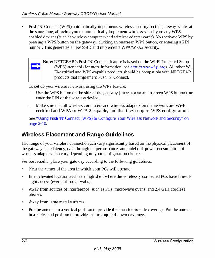
Note: NETGEAR’s Push 'N' Connect feature is based on the Wi-Fi Protected Setup (WPS) standard (for more information, see http://www.wi-fi.org). All other Wi-Fi-certified and WPS-capable products should be compatible with NETGEAR products that implement Push 'N' Connect.
2-2 Wireless Configuration
v1.1, May 2009
Wireless Cable Modem Gateway CGD24G User Manual
• If using multiple access points, it is better if adjacent access points use different radio frequency channels to reduce interference. The recommended channel spacing between adjacent access points is 5 channels (for example, use Channels 1 and 6, or 6 and 11).
The time it takes to establish a wireless connection can vary depending on both your security settings and placement. WEP connections can take slightly longer to establish. Also, WEP encryption can consume more battery power on a notebook computer.
Wireless Security OptionsIndoors, computers can connect over 802.11g wireless networks at a maximum range of up to 300 feet. Such distances can allow for others outside your immediate area to access your network.
Unlike wired network data, your wireless data transmissions can extend beyond your walls and can be received by anyone with a compatible adapter. For this reason, use the security features of your wireless equipment. The CGD24G gateway provides highly effective security features which are covered in detail in this chapter. Deploy the security features appropriate to your needs.
There are several ways you can enhance the security of your wireless network:
• WEP. Wired Equivalent Privacy (WEP) data encryption provides data security. WEP Shared Key authentication and WEP data encryption block all but the most determined eavesdropper. This data encryption mode has been superseded by WPA-PSK and WPA2-PSK.
• WPA-PSK (TKIP), WPA2-PSK (AES). Wi-Fi Protected Access (WPA) using a pre-shared key to perform authentication and generate the initial data encryption keys. The very strong authentication along with dynamic per frame re-keying of WPA makes it virtually impossible to compromise.
• Restrict access to your router.
For more information about wireless technology, see the link to the online document in “Wireless Networking Basics” in Appendix B.
Manually Configuring Your Wireless Settings and Security
You can view or manually configure the wireless settings for the gateway in the Wireless Settings screen. If you want to make changes, make sure to note the current settings first.
Note: If you use a wireless computer to change the wireless network name (SSID) or wireless security settings, you will be disconnected when you click Apply. To avoid this problem, use a computer with a wired connection to access the gateway.
Wireless Configuration 2-3
v1.1, May 2009
Wireless Cable Modem Gateway CGD24G User Manual
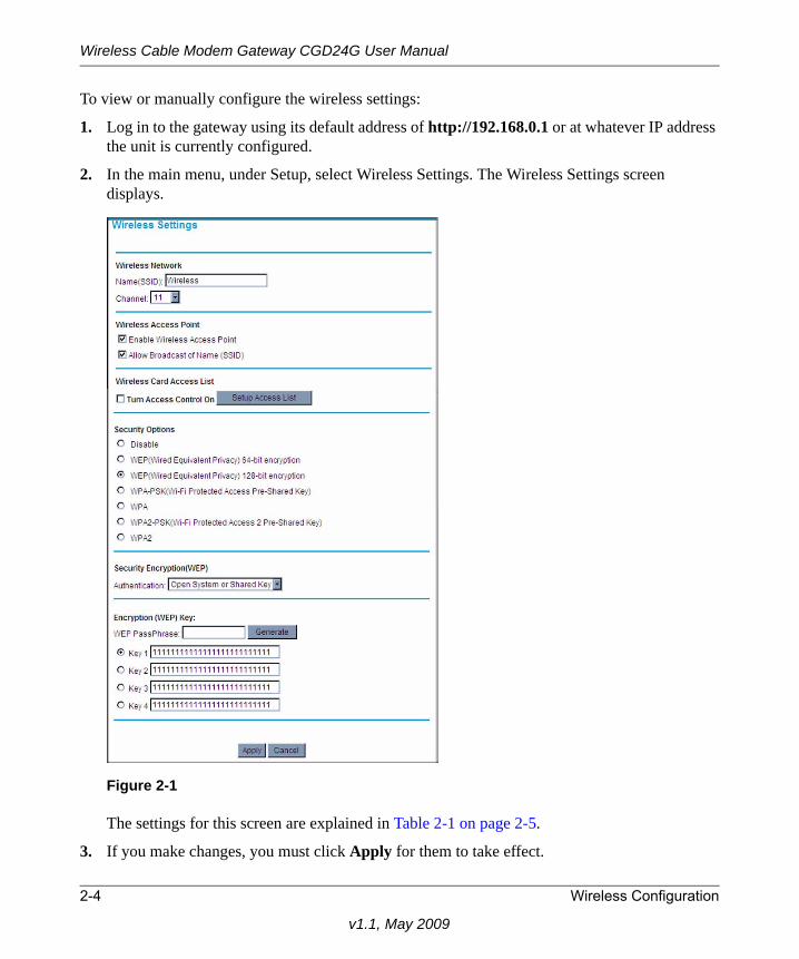
To view or manually configure the wireless settings:
1. Log in to the gateway using its default address of http://192.168.0.1 or at whatever IP address the unit is currently configured.
2. In the main menu, under Setup, select Wireless Settings. The Wireless Settings screen displays.
The settings for this screen are explained in Table 2-1 on page 2-5.
3. If you make changes, you must click Apply for them to take effect.
Figure 2-1
2-4 Wireless Configuration
v1.1, May 2009
Wireless Cable Modem Gateway CGD24G User Manual
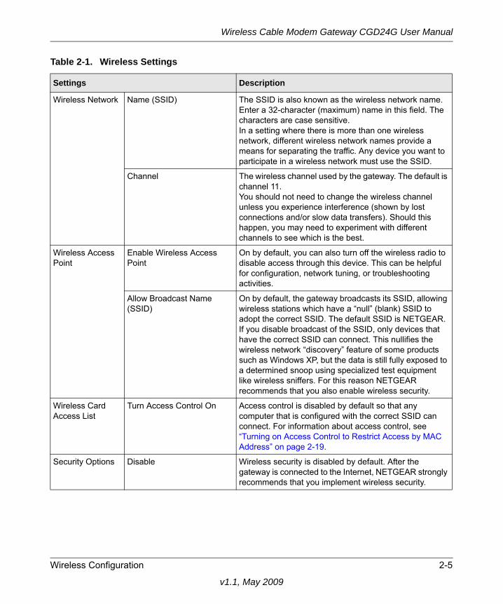
Table 2-1. Wireless Settings
Settings Description
Wireless Network Name (SSID) The SSID is also known as the wireless network name. Enter a 32-character (maximum) name in this field. The characters are case sensitive. In a setting where there is more than one wireless network, different wireless network names provide a means for separating the traffic. Any device you want to participate in a wireless network must use the SSID.
Channel The wireless channel used by the gateway. The default is channel 11.You should not need to change the wireless channel unless you experience interference (shown by lost connections and/or slow data transfers). Should this happen, you may need to experiment with different channels to see which is the best.
Wireless Access Point
Enable Wireless Access Point
On by default, you can also turn off the wireless radio to disable access through this device. This can be helpful for configuration, network tuning, or troubleshooting activities.
Allow Broadcast Name (SSID)
On by default, the gateway broadcasts its SSID, allowing wireless stations which have a “null” (blank) SSID to adopt the correct SSID. The default SSID is NETGEAR.If you disable broadcast of the SSID, only devices that have the correct SSID can connect. This nullifies the wireless network “discovery” feature of some products such as Windows XP, but the data is still fully exposed to a determined snoop using specialized test equipment like wireless sniffers. For this reason NETGEAR recommends that you also enable wireless security.
Wireless Card Access List
Turn Access Control On Access control is disabled by default so that any computer that is configured with the correct SSID can connect. For information about access control, see “Turning on Access Control to Restrict Access by MAC Address” on page 2-19.
Security Options Disable Wireless security is disabled by default. After the gateway is connected to the Internet, NETGEAR strongly recommends that you implement wireless security.
Wireless Configuration 2-5
v1.1, May 2009
Wireless Cable Modem Gateway CGD24G User Manual
Configuring WEP (Wired Equivalent Privacy) Wireless Security
To configure WEP data encryption:
1. Log in to the gateway using its default address of http://192.168.0.1 or at whatever IP address the unit is currently configured. Use the default user name of admin and default password of password, or the password you have set up.
2. In the main menu, under Setup, select Wireless Settings.
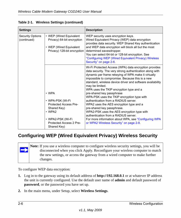
Security Options (continued)
• WEP (Wired Equivalent Privacy) 64-bit encryption
• WEP (Wired Equivalent Privacy) 128-bit encryption
WEP security uses encryption keys. Wired Equivalent Privacy (WEP) data encryption provides data security. WEP Shared Key authentication and WEP data encryption will block all but the most determined eavesdropper. You can select 64-bit or 128-bit encryption. See “Configuring WEP (Wired Equivalent Privacy) Wireless Security” on page 2-6.
• WPA
• WPA-PSK (Wi-Fi Protected Access Pre-Shared Key)
• WPA2
• WPA2-PSK (Wi-Fi Protected Access 2 Pre-Shared Key)
Wi-Fi Protected Access (WPA) data encryption provides data security. The very strong authentication along with dynamic per frame rekeying of WPA make it virtually impossible to compromise. Because this is a new standard, wireless device driver and software availability may be limited.WPA uses the TKIP encryption type and apre-shared key passphraseWPA-PSK uses the TKIP encryption type with authentication from a RADIUS server.WPA2 uses the AES encryption type and apre-shared key passphrase. WPA2-PSK uses the AES encryption type with authentication from a RADIUS server.For more information about WPA, see “Configuring WPA or WPA2 Wireless Security” on page 2-8.
Note: If you use a wireless computer to configure wireless security settings, you will be disconnected when you click Apply. Reconfigure your wireless computer to match the new settings, or access the gateway from a wired computer to make further changes.
Table 2-1. Wireless Settings (continued)
Settings Description
2-6 Wireless Configuration
v1.1, May 2009
Wireless Cable Modem Gateway CGD24G User Manual
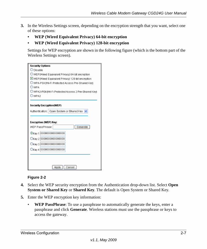
3. In the Wireless Settings screen, depending on the encryption strength that you want, select one of these options:• WEP (Wired Equivalent Privacy) 64-bit encryption• WEP (Wired Equivalent Privacy) 128-bit encryption
Settings for WEP encryption are shown in the following figure (which is the bottom part of the Wireless Settings screen).
4. Select the WEP security encryption from the Authentication drop-down list. Select Open System or Shared Key or Shared Key. The default is Open System or Shared Key.
5. Enter the WEP encryption key information:
• WEP PassPhrase: To use a passphrase to automatically generate the keys, enter a passphrase and click Generate. Wireless stations must use the passphrase or keys to access the gateway.
Figure 2-2
Wireless Configuration 2-7
v1.1, May 2009
Wireless Cable Modem Gateway CGD24G User Manual
• Key 1 through Key 4: You can manually enter the four data encryption keys. These values must be identical on all computers and access points in your network. For 64-bit WEP, enter 10 hexadecimal digits (any combination of 0–9 or A–F). For 128-bit WEP, enter 26 hexadecimal digits.
• Select which of the four keys will be the default. Data transmissions are always encrypted using the default key. The other keys can only be used to decrypt received data. The four entries are disabled if WPA-PSK or WPA authentication is selected.
6. Click Apply to save your settings.
Configuring WPA or WPA2 Wireless Security
To configure WPA in the gateway:
1. Log in to the gateway using its default address of http://192.168.0.1 or at whatever IP address the unit is currently configured. Use the default user name of admin and default password of password, or the password you have set up.
2. In the main menu, under Setup, select Wireless Settings.
3. Select either one of the WPA settings:
• WPA-PSK. This setting provides the TKIP encryption type and a pre-shared key passphrase.
• WPA. This setting provides the TKIP encryption type with authentication from a RADIUS server.
• WPA2-PSK. This setting provides the AES encryption type and a pre-shared key passphrase.
Note: If you use a wireless computer to configure WEP settings, you will be disconnected when you click Apply. Reconfigure your wireless adapter to match the new settings or access the gateway from a wired computer to make any further changes.
Note: Not all wireless adapters support WPA. Furthermore, client software is required on the client. Windows XP and Windows 2000 with Service Pack 3 or above do include the client software that supports WPA. The wireless adapter hardware and driver must also support WPA. Consult the product documentation for your wireless adapter and WPA client software for instructions on configuring WPA settings.
2-8 Wireless Configuration
v1.1, May 2009
Wireless Cable Modem Gateway CGD24G User Manual
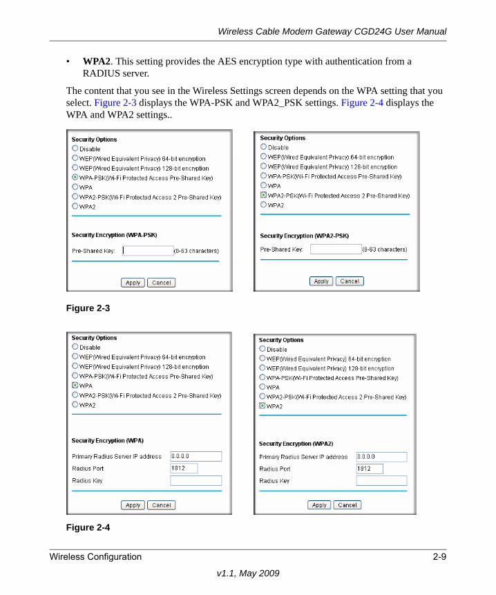
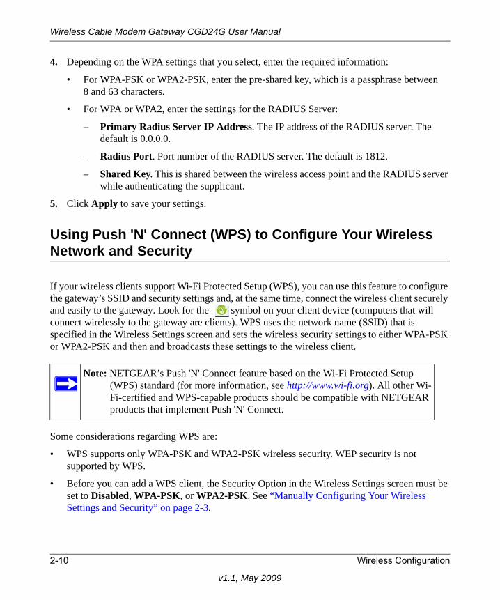
• WPA2. This setting provides the AES encryption type with authentication from a RADIUS server.
The content that you see in the Wireless Settings screen depends on the WPA setting that you select. Figure 2-3 displays the WPA-PSK and WPA2_PSK settings. Figure 2-4 displays the WPA and WPA2 settings..
Figure 2-3
Figure 2-4
Wireless Configuration 2-9
v1.1, May 2009
Wireless Cable Modem Gateway CGD24G User Manual
4. Depending on the WPA settings that you select, enter the required information:
• For WPA-PSK or WPA2-PSK, enter the pre-shared key, which is a passphrase between 8 and 63 characters.
• For WPA or WPA2, enter the settings for the RADIUS Server:
– Primary Radius Server IP Address. The IP address of the RADIUS server. The default is 0.0.0.0.
– Radius Port. Port number of the RADIUS server. The default is 1812.
– Shared Key. This is shared between the wireless access point and the RADIUS server while authenticating the supplicant.
5. Click Apply to save your settings.
Using Push 'N' Connect (WPS) to Configure Your Wireless Network and Security
If your wireless clients support Wi-Fi Protected Setup (WPS), you can use this feature to configure the gateway’s SSID and security settings and, at the same time, connect the wireless client securely and easily to the gateway. Look for the symbol on your client device (computers that will connect wirelessly to the gateway are clients). WPS uses the network name (SSID) that is specified in the Wireless Settings screen and sets the wireless security settings to either WPA-PSK or WPA2-PSK and then and broadcasts these settings to the wireless client.
Some considerations regarding WPS are:
• WPS supports only WPA-PSK and WPA2-PSK wireless security. WEP security is not supported by WPS.
• Before you can add a WPS client, the Security Option in the Wireless Settings screen must be set to Disabled, WPA-PSK, or WPA2-PSK. See “Manually Configuring Your Wireless Settings and Security” on page 2-3.
Note: NETGEAR’s Push 'N' Connect feature based on the Wi-Fi Protected Setup (WPS) standard (for more information, see http://www.wi-fi.org). All other Wi-Fi-certified and WPS-capable products should be compatible with NETGEAR products that implement Push 'N' Connect.
2-10 Wireless Configuration
v1.1, May 2009
Wireless Cable Modem Gateway CGD24G User Manual
A WPS client can be added using the Push Button method or the PIN method.
• Using the Push Button. This is the preferred method. See the following section, “Using a WPS Button to Add a WPS Client.
• Entering a PIN. For information about using the PIN method, see “Using a PIN Entry to Add a WPS Client” on page 2-12.
Using a WPS Button to Add a WPS ClientAny wireless computer or wireless adapter that will connect to the gateway wirelessly is a client. The client must support a WPS PIN, and must have a WPS configuration utility, such as the NETGEAR Smart Wizard or Atheros Jumpstart.
Before you can add a WPS client, the Security Option in the Wireless Settings screen must be set to Disabled, WPA-PSK, or WPA2-PSK. See “Manually Configuring Your Wireless Settings and Security” on page 2-3.
To use the gateway WPS button to add a WPS client:
1. Log in to the gateway using its default address of http://192.168.0.1 or at whatever IP address the unit is currently configured.
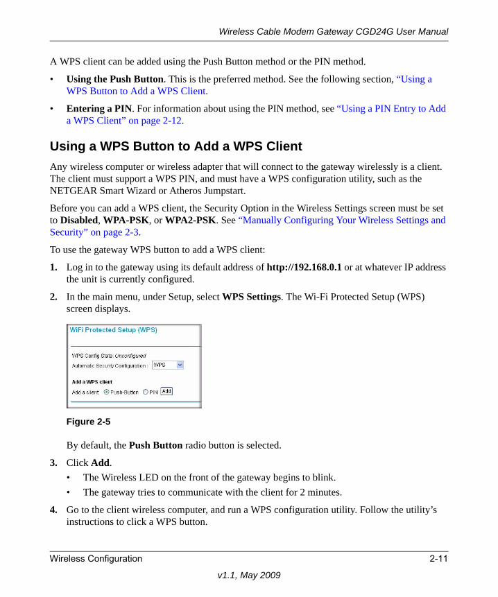
2. In the main menu, under Setup, select WPS Settings. The Wi-Fi Protected Setup (WPS) screen displays.
By default, the Push Button radio button is selected.
3. Click Add.• The Wireless LED on the front of the gateway begins to blink.• The gateway tries to communicate with the client for 2 minutes.
4. Go to the client wireless computer, and run a WPS configuration utility. Follow the utility’s instructions to click a WPS button.
Figure 2-5
Wireless Configuration 2-11
v1.1, May 2009
Wireless Cable Modem Gateway CGD24G User Manual
When the gateway adds the WPS client, it sends the SSID and WPA-PSK or WPA2-PSK configuration to the client.
To access the Internet from any computer connected to your gateway, launch a browser such as Microsoft Internet Explorer or Mozilla Firefox. You should see the gateway’s Internet LED blink, indicating communication to the ISP.
Using a PIN Entry to Add a WPS ClientAny wireless computer or wireless adapter that will connect to the gateway wirelessly is a client. The client must support a WPS PIN, and must have a WPS configuration utility, such as the NETGEAR Smart Wizard or Atheros Jumpstart.
Before you can add a WPS client, the Security Option in the Wireless Settings screen must be set to Disabled, WPA-PSK, or WPA2-PSK. See “Manually Configuring Your Wireless Settings and Security” on page 2-3.
To use a PIN to add a WPS client:
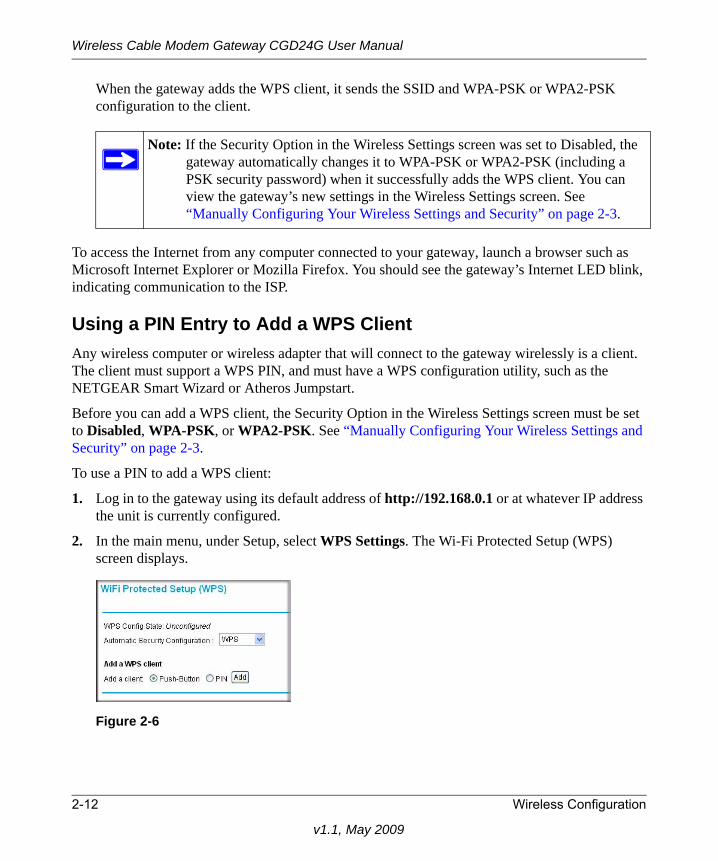
1. Log in to the gateway using its default address of http://192.168.0.1 or at whatever IP address the unit is currently configured.
2. In the main menu, under Setup, select WPS Settings. The Wi-Fi Protected Setup (WPS) screen displays.
Note: If the Security Option in the Wireless Settings screen was set to Disabled, the gateway automatically changes it to WPA-PSK or WPA2-PSK (including a PSK security password) when it successfully adds the WPS client. You can view the gateway’s new settings in the Wireless Settings screen. See “Manually Configuring Your Wireless Settings and Security” on page 2-3.
Figure 2-6
2-12 Wireless Configuration
v1.1, May 2009
Wireless Cable Modem Gateway CGD24G User Manual
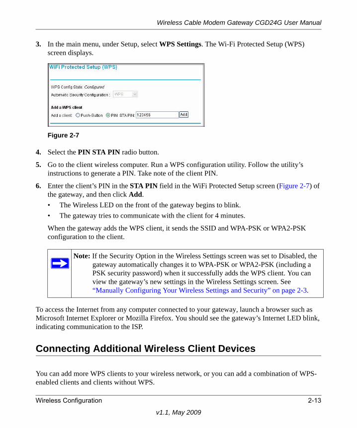
3. In the main menu, under Setup, select WPS Settings. The Wi-Fi Protected Setup (WPS) screen displays.
4. Select the PIN STA PIN radio button.
5. Go to the client wireless computer. Run a WPS configuration utility. Follow the utility’s instructions to generate a PIN. Take note of the client PIN.
6. Enter the client’s PIN in the STA PIN field in the WiFi Protected Setup screen (Figure 2-7) of the gateway, and then click Add. • The Wireless LED on the front of the gateway begins to blink.• The gateway tries to communicate with the client for 4 minutes.
When the gateway adds the WPS client, it sends the SSID and WPA-PSK or WPA2-PSK configuration to the client.
To access the Internet from any computer connected to your gateway, launch a browser such as Microsoft Internet Explorer or Mozilla Firefox. You should see the gateway’s Internet LED blink, indicating communication to the ISP.
Connecting Additional Wireless Client Devices
You can add more WPS clients to your wireless network, or you can add a combination of WPS-enabled clients and clients without WPS.
Figure 2-7
Note: If the Security Option in the Wireless Settings screen was set to Disabled, the gateway automatically changes it to WPA-PSK or WPA2-PSK (including a PSK security password) when it successfully adds the WPS client. You can view the gateway’s new settings in the Wireless Settings screen. See “Manually Configuring Your Wireless Settings and Security” on page 2-3.
Wireless Configuration 2-13
v1.1, May 2009

Wireless Cable Modem Gateway CGD24G User Manual
Adding Just WPS ClientsTo add a wireless client device that is WPS-enabled, follow the procedures in “Using a WPS Button to Add a WPS Client” on page 2-11 or “Using a PIN Entry to Add a WPS Client” on page 2-12.
Adding Both WPS and Non-WPS ClientsFor non-WPS clients, you cannot use the WPS setup procedures to add them to the wireless network. You must record, and then manually enter your security settings (see “Manually Configuring Your Wireless Settings and Security” on page 2-3).
To connect a combination of non-WPS enabled and WPS-Enabled clients to the gateway:
1. Restore the gateway to its factory default settings (press the Restore Factory Settings button on the rear panel of the gateway for 5 seconds).
When the factory settings are restored, all existing wireless clients are disassociated and disconnected from the gateway.
2. Configure the network name (SSID), select the WPA/PSK or WPA2/PSK radio button on the Wireless Settings screen (see “Manually Configuring Your Wireless Settings and Security” on page 2-3). and click Apply. On the WPA/PSK + WPA2/PSK screen, select a passphrase and click Apply. Record this information to add additional clients.
3. For the non-WPS devices that you want to connect, open the networking utility and follow the utility’s instructions to enter the security settings that you selected in Step 2 (the SSID, WPA/PSK or WPA2/PSK security method, and passphrase).
4. For the WPS devices that you want to connect, follow the procedure “Using a WPS Button to Add a WPS Client” on page 2-11 or “Using a PIN Entry to Add a WPS Client” on page 2-12.
The settings that you configured in Step 2 are broadcast to the WPS devices so that they can connect to the gateway.
Wireless Guest Networks
A wireless guest network allows you to provide guests access to your wireless network without prior authorization of each individual guest. You can configure up to three wireless guest networks and specify the security options for each wireless guest network.
2-14 Wireless Configuration
v1.1, May 2009
Wireless Cable Modem Gateway CGD24G User Manual
How to Configure a Wireless Guest NetworkTo configure a wireless guest network:
1. Log in to the gateway using its default address of http://192.168.0.1 or at whatever IP address the unit is currently configured. Use the default user name of admin and default password of password, or the password you have set up.
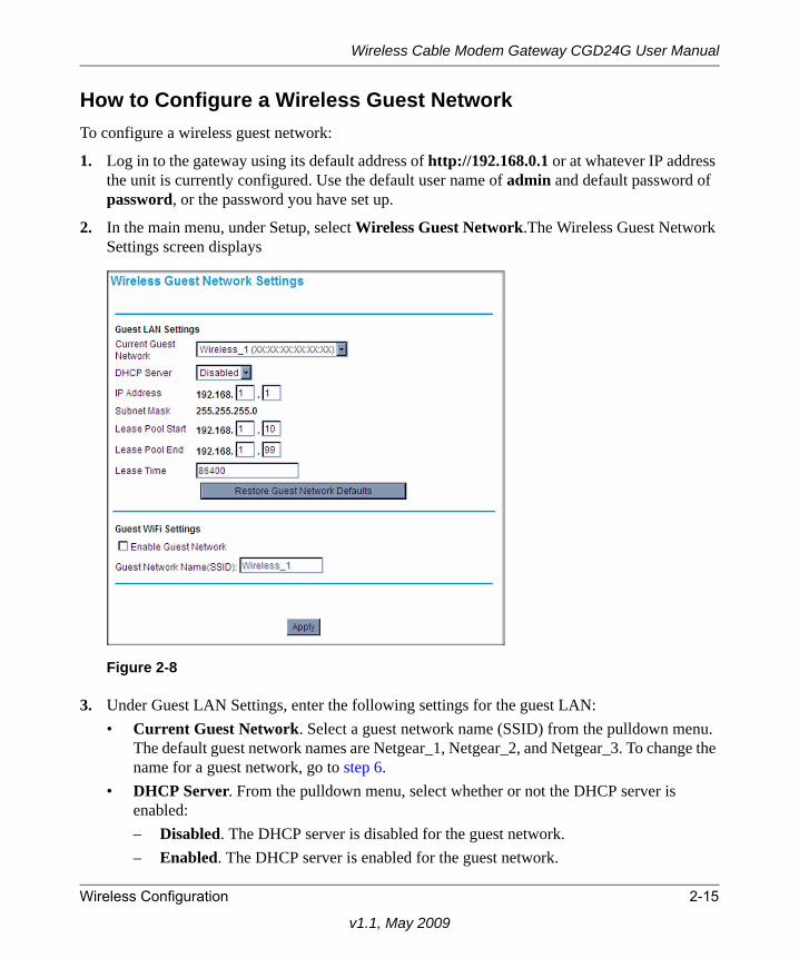
2. In the main menu, under Setup, select Wireless Guest Network.The Wireless Guest Network Settings screen displays
3. Under Guest LAN Settings, enter the following settings for the guest LAN:• Current Guest Network. Select a guest network name (SSID) from the pulldown menu.
The default guest network names are Netgear_1, Netgear_2, and Netgear_3. To change the name for a guest network, go to step 6.
• DHCP Server. From the pulldown menu, select whether or not the DHCP server is enabled:– Disabled. The DHCP server is disabled for the guest network.– Enabled. The DHCP server is enabled for the guest network.
Figure 2-8
Wireless Configuration 2-15
v1.1, May 2009
Wireless Cable Modem Gateway CGD24G User Manual
• IP Address. Enter the IP address for the guest network The default IP addresses are as follows:– Netgear_1: 192.168.1.1– Netgear_2: 192.168.2.1– Netgear_3: 192.168.3.1
• Lease Pool Start. Enter the lease pool start IP address for the guest network. The default lease pool start IP addresses are as follows:– Netgear_1: 192.168.1.10– Netgear_2: 192.168.2.10– Netgear_3: 192.168.3.10
• Lease Pool End. Enter the lease pool end IP address for the guest network. The default lease pool end IP addresses are as follows:– Netgear_1: 192.168.1.99– Netgear_2: 192.168.2.99– Netgear_3: 192.168.3.99
• Lease Time. Enter the lease time for the guest network. The default is 86400 seconds (24 hours).
4. Under Guest WiFi Settings, select the Enable Guest Network check box.
5. Click Apply to enable the selected guest network. The screen expands and the security options display. To configure the security options, see “How to Configure Wireless Security for a Wireless Guest Network” on page 2-17.”
6. You can now change the Guest Network Name (SSID) for the selected guest network. Enter a value of up to 32 alphanumeric characters. For the selected guest network, the same name must be assigned to all wireless devices in your network. After you have changed the name, click Apply again to activate the new name.
Note: The subnet mask has a permanent address of 255.255.255.
Note: NETGEAR strongly recommends that you change the default guest network name (SSID) from the default name to a different name. Note that the name is case-sensitive. For example, GuestNetwork is not the same as Guestnetwork.
2-16 Wireless Configuration
v1.1, May 2009
Wireless Cable Modem Gateway CGD24G User Manual
How to Configure Wireless Security for a Wireless Guest Network
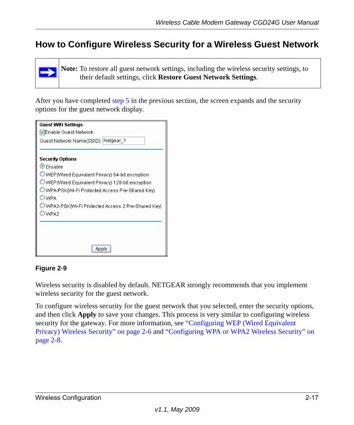
After you have completed step 5 in the previous section, the screen expands and the security options for the guest network display.
Wireless security is disabled by default. NETGEAR strongly recommends that you implement wireless security for the guest network.
To configure wireless security for the guest network that you selected, enter the security options, and then click Apply to save your changes. This process is very similar to configuring wireless security for the gateway. For more information, see “Configuring WEP (Wired Equivalent Privacy) Wireless Security” on page 2-6 and “Configuring WPA or WPA2 Wireless Security” on page 2-8.
Note: To restore all guest network settings, including the wireless security settings, to their default settings, click Restore Guest Network Settings.
Figure 2-9
Wireless Configuration 2-17
v1.1, May 2009
Wireless Cable Modem Gateway CGD24G User Manual
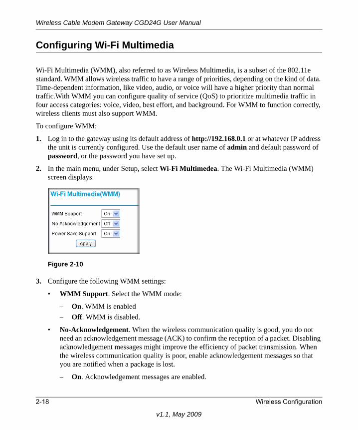
Configuring Wi-Fi Multimedia
Wi-Fi Multimedia (WMM), also referred to as Wireless Multimedia, is a subset of the 802.11e standard. WMM allows wireless traffic to have a range of priorities, depending on the kind of data. Time-dependent information, like video, audio, or voice will have a higher priority than normal traffic.With WMM you can configure quality of service (QoS) to prioritize multimedia traffic in four access categories: voice, video, best effort, and background. For WMM to function correctly, wireless clients must also support WMM.
To configure WMM:
1. Log in to the gateway using its default address of http://192.168.0.1 or at whatever IP address the unit is currently configured. Use the default user name of admin and default password of password, or the password you have set up.
2. In the main menu, under Setup, select Wi-Fi Multimedea. The Wi-Fi Multimedia (WMM) screen displays.
3. Configure the following WMM settings:
• WMM Support. Select the WMM mode:
– On. WMM is enabled– Off. WMM is disabled.
• No-Acknowledgement. When the wireless communication quality is good, you do not need an acknowledgement message (ACK) to confirm the reception of a packet. Disabling acknowledgement messages might improve the efficiency of packet transmission. When the wireless communication quality is poor, enable acknowledgement messages so that you are notified when a package is lost.
– On. Acknowledgement messages are enabled.
Figure 2-10
2-18 Wireless Configuration
v1.1, May 2009
Wireless Cable Modem Gateway CGD24G User Manual
– Off. Acknowledgement messages are disabled.
• Power Save Support. Select the power save mode to conserve battery power in smaller devices that are connected to the gateway:
– On. Power save support is enabled.– Off. Power save support is disabled.
4. Click Apply to save your settings.
Turning on Access Control to Restrict Access by MAC Address
By default, any wireless PC that is configured with the correct SSID and WEP/WPA settings will be allowed to access to your wireless network. For increased security, you can restrict access to the wireless network to only allow specific PCs based on their MAC addresses.
You can restrict access to only trusted PCs so that unknown PCs cannot wirelessly connect to the CGD24G gateway. MAC address filtering adds an obstacle against unwanted access to your network, but the data broadcast over the wireless link is fully exposed.
To restrict access based on MAC addresses:
1. Log in to the gateway using its default address of http://192.168.0.1 or at whatever IP address the unit is currently configured. Use the default user name of admin and default password of password, or the password you have set up.
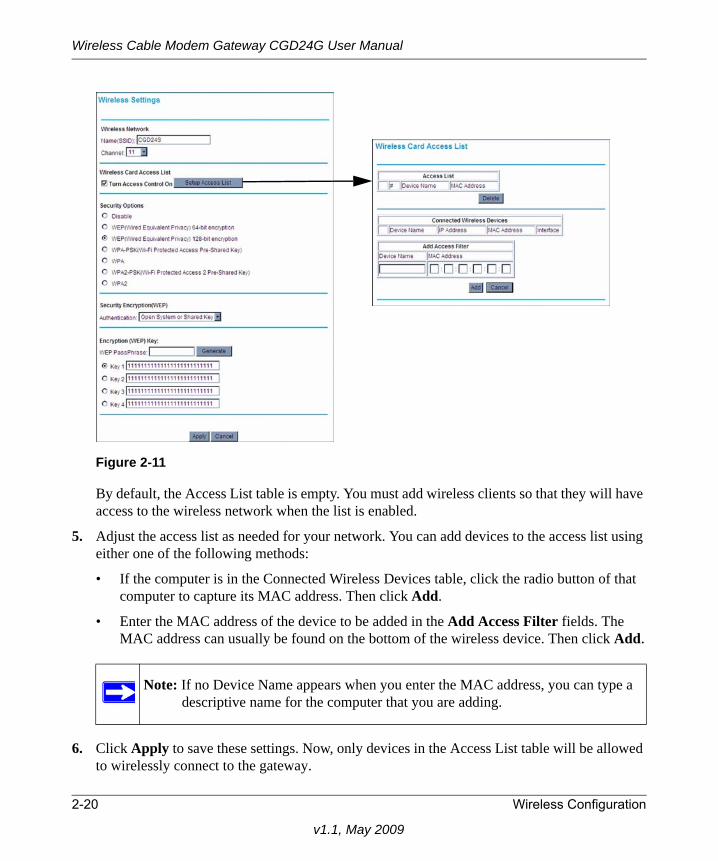
2. In the main menu, under Setup, select Wireless Settings. In the Wireless Settings screen, select the Turn Access Control On check box (see Figure 2-11 on page 2-20).
3. When you enable access control, the access point only accepts connections from clients on the selected access control list. This provides an additional layer of security.
4. Click the Setup Access List button to display the Wireless Card Access List screen.
Note: If you are configuring the gateway from a wireless computer, make sure to add your computer’s MAC address to the Access List. Otherwise you will lose your wireless connection when you click Apply. You must then access the gateway from a wired computer, or from a wireless computer that is on the access control list, to make any further changes.
Wireless Configuration 2-19
v1.1, May 2009
Wireless Cable Modem Gateway CGD24G User Manual
By default, the Access List table is empty. You must add wireless clients so that they will have access to the wireless network when the list is enabled.
5. Adjust the access list as needed for your network. You can add devices to the access list using either one of the following methods:
• If the computer is in the Connected Wireless Devices table, click the radio button of that computer to capture its MAC address. Then click Add.
• Enter the MAC address of the device to be added in the Add Access Filter fields. The MAC address can usually be found on the bottom of the wireless device. Then click Add.
6. Click Apply to save these settings. Now, only devices in the Access List table will be allowed to wirelessly connect to the gateway.
Figure 2-11
Note: If no Device Name appears when you enter the MAC address, you can type a descriptive name for the computer that you are adding.
2-20 Wireless Configuration
v1.1, May 2009
Chapter 3Content Filtering and Firewall Rules
This chapter describes how to use content filtering and firewall rules for the gateway.
This chapter includes:
• “Configuring Logs” on this page• “Blocking Keywords, Sites, and Services” on page 3-2• “Firewall Rules—Port Forwarding and Port Blocking” on page 3-5
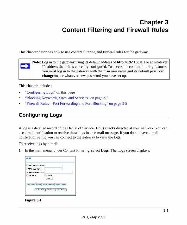
Configuring Logs
A log is a detailed record of the Denial of Service (DoS) attacks directed at your network. You can use e-mail notification to receive these logs in an e-mail message. If you do not have e-mail notification set up you can connect to the gateway to view the logs.
To receive logs by e-mail:
1. In the main menu, under Content Filtering, select Logs. The Logs screen displays.
Note: Log in to the gateway using its default address of http://192.168.0.1 or at whatever IP address the unit is currently configured. To access the content filtering features you must log in to the gateway with the mso user name and its default password changeme, or whatever new password you have set up.
Figure 3-1
3-1
v1.1, May 2009
Wireless Cable Modem Gateway CGD24G User Manual
2. Enter the following information:
• Contact Email Address. Enter an e-mail address to which the logs will be sent. Use a fulle-mail address (for example, [email protected]).
• SMTP Server Name. Enter the outgoing SMTP mail server of your ISP (for example, mail.myISP.com). If you leave this box blank, no alerts or logs will be sent.
• Sender Email Address. Enter an e-mail address from which the logs will be sent. Use a full e-mail address (for example, [email protected]).
3. Select the E-mail Alerts Enable check box to activate the e-mail alerts.
4. Click Apply to save your settings.
For information about event logs, see “Viewing the Event Log” on page 4-6.
Blocking Keywords, Sites, and Services
The gateway provides a variety of options for blocking Internet based content and communications services. With its content filtering feature, the gateway prevents objectionable content from reaching your PCs. The gateway allows you to control access to Internet content by screening for keywords within Web addresses. It also has the capability to block access to all sites except those that are explicitly allowed. Key content filtering options include:• Blocking access from your LAN to Internet locations that contain keywords that your specify.• Blocking access to websites that you specify as off-limits.• Allowing access to only websites that you specify as allowed.
Blocking Keywords and DomainsThe gateway allows you to restrict access to Internet content based on functions such as Web address keywords and Web domains. A domain name is the name of a particular website. For example, for the address www.NETGEAR.com, the domain name is NETGEAR.com.
To block keywords and domains:
3-2 Content Filtering and Firewall Rules
v1.1, May 2009
Wireless Cable Modem Gateway CGD24G User Manual
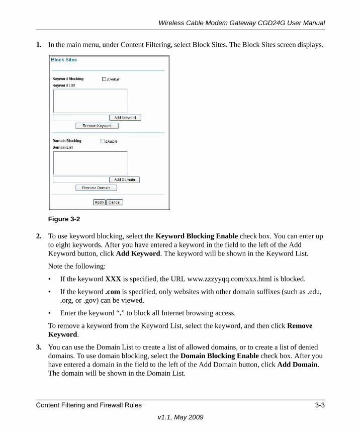
1. In the main menu, under Content Filtering, select Block Sites. The Block Sites screen displays.
2. To use keyword blocking, select the Keyword Blocking Enable check box. You can enter up to eight keywords. After you have entered a keyword in the field to the left of the Add Keyword button, click Add Keyword. The keyword will be shown in the Keyword List.
Note the following:
• If the keyword XXX is specified, the URL www.zzzyyqq.com/xxx.html is blocked.
• If the keyword .com is specified, only websites with other domain suffixes (such as .edu, .org, or .gov) can be viewed.
• Enter the keyword “.” to block all Internet browsing access.
To remove a keyword from the Keyword List, select the keyword, and then click Remove Keyword.
3. You can use the Domain List to create a list of allowed domains, or to create a list of denied domains. To use domain blocking, select the Domain Blocking Enable check box. After you have entered a domain in the field to the left of the Add Domain button, click Add Domain. The domain will be shown in the Domain List.
Figure 3-2
Content Filtering and Firewall Rules 3-3
v1.1, May 2009
Wireless Cable Modem Gateway CGD24G User Manual
If the domain www.zzzyyqq.com is specified, the URL <http://www.zzzyyqq.com/xxx.html> is blocked, along with all other URLs in the www.zzzyyqq.com site.
To remove a domain from the Domain List, select the domain, and then click Remove Domain.
4. Click Apply to save your settings.
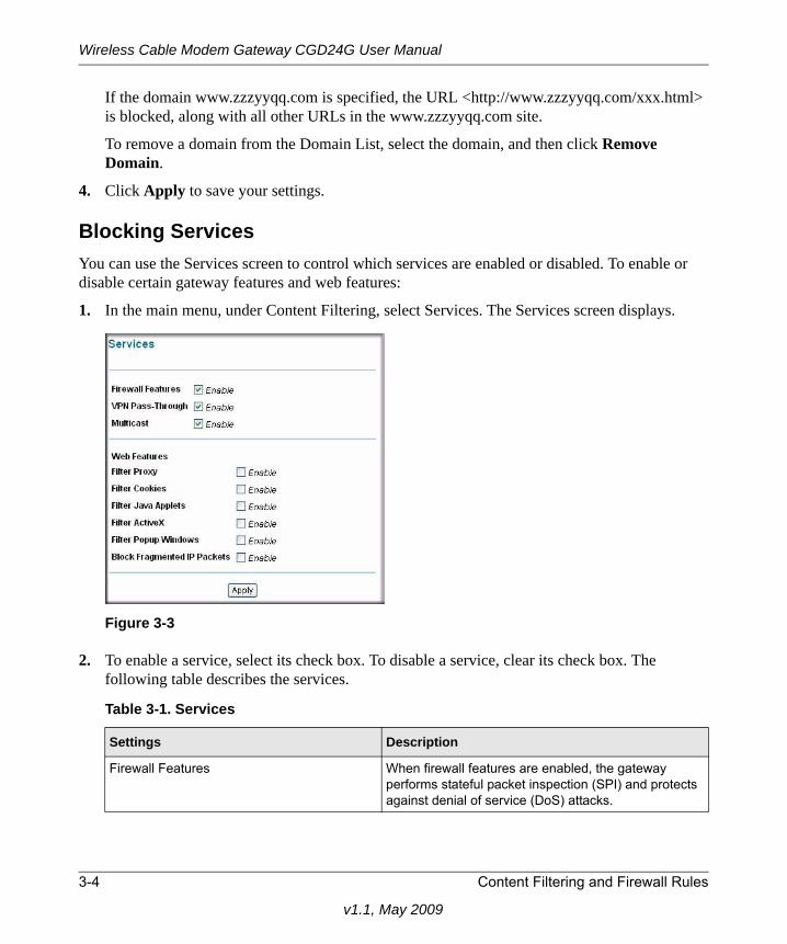
Blocking ServicesYou can use the Services screen to control which services are enabled or disabled. To enable or disable certain gateway features and web features:
1. In the main menu, under Content Filtering, select Services. The Services screen displays.
2. To enable a service, select its check box. To disable a service, clear its check box. The following table describes the services.
Figure 3-3
Table 3-1. Services
Settings Description
Firewall Features When firewall features are enabled, the gateway performs stateful packet inspection (SPI) and protects against denial of service (DoS) attacks.
3-4 Content Filtering and Firewall Rules
v1.1, May 2009
Wireless Cable Modem Gateway CGD24G User Manual
3. Click Apply to save your settings.
Firewall Rules—Port Forwarding and Port Blocking
A firewall has two default rules, one for inbound traffic (WAN to LAN) and one for outbound traffic. • Inbound Rules (Port Forwarding)
These rules restrict access from outsiders. The default rule is to block all access from outside except responses to requests from the LAN side. You can use port forwarding to add predefined or custom rules to specify exceptions to the default rule.
• Outbound Rules (Port Blocking)These rules control access to outside resources from local users.The default rule is to allow all access from the LAN side to the outside. You can use port blocking to add predefined or custom rules to specify exceptions to the default rules.
Configuring Port ForwardingBecause the gateway uses Network Address Translation (NAT), your network presents only one IP address to the Internet, and outside users cannot directly address any of your local computers. However, by defining an inbound rule you can make a local server (for example, a web server or
VPN Pass Through When VPN passthrough is enabled, IPSec and PPTP traffic are forwarded. When it is disabled, this traffic is blocked.
Multicast When multicast is enabled, the gateway passes multicasting streams through the firewall.
Web Features Filter Proxy
When enabled, these features are not blocked by the firewall. When disabled, these features are blocked by the firewall. You can enable or disable each of these features individually.
Filter Cookies
Filter Java Applets
Filter ActiveX
Filter Popup Windows
Block Fragmented IP Packets
Table 3-1. Services (continued)
Settings Description
Content Filtering and Firewall Rules 3-5
v1.1, May 2009
Wireless Cable Modem Gateway CGD24G User Manual
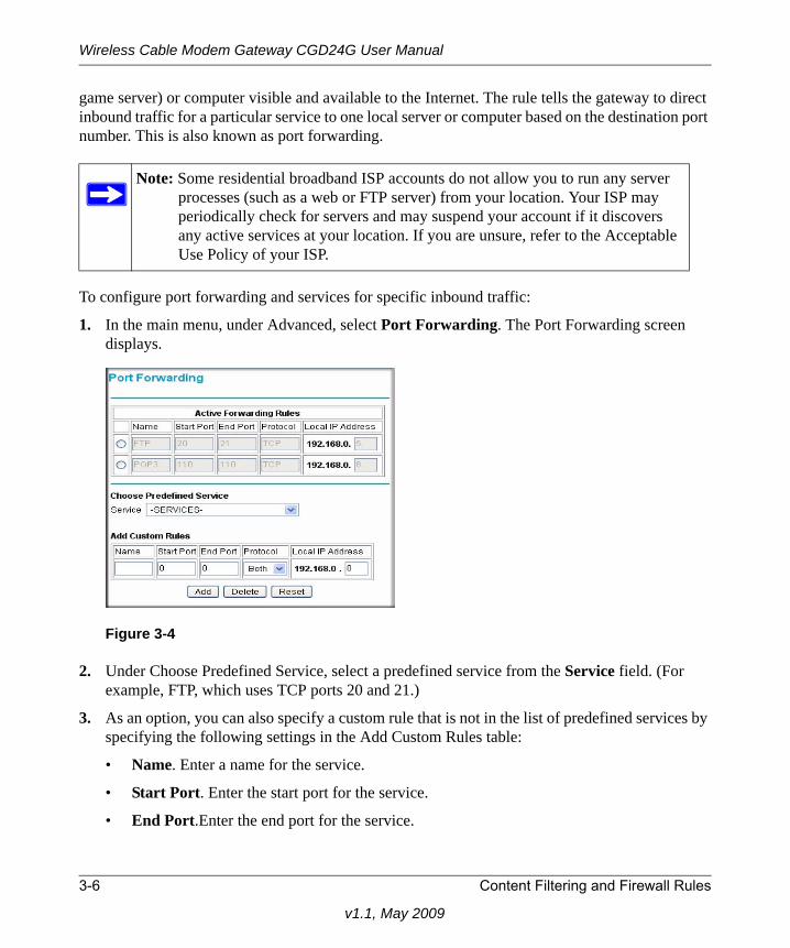
game server) or computer visible and available to the Internet. The rule tells the gateway to direct inbound traffic for a particular service to one local server or computer based on the destination port number. This is also known as port forwarding.
To configure port forwarding and services for specific inbound traffic:
1. In the main menu, under Advanced, select Port Forwarding. The Port Forwarding screen displays.
2. Under Choose Predefined Service, select a predefined service from the Service field. (For example, FTP, which uses TCP ports 20 and 21.)
3. As an option, you can also specify a custom rule that is not in the list of predefined services by specifying the following settings in the Add Custom Rules table:
• Name. Enter a name for the service.
• Start Port. Enter the start port for the service.
• End Port.Enter the end port for the service.
Note: Some residential broadband ISP accounts do not allow you to run any server processes (such as a web or FTP server) from your location. Your ISP may periodically check for servers and may suspend your account if it discovers any active services at your location. If you are unsure, refer to the Acceptable Use Policy of your ISP.
Figure 3-4
3-6 Content Filtering and Firewall Rules
v1.1, May 2009
Wireless Cable Modem Gateway CGD24G User Manual
• Protocol. Select the protocol for the ports:
– TCP. Select TCP only.
– UDP. Select UDP only.
– Both. Select both TCP and UDP.
• Local IP Address. Complete the local IP address for the computer that is using the service.
4. Perform one of the following actions:
• Click Add to save your settings. The Active Forwarding Rules table now displays the list of ports that are currently forwarded.
• To delete a service, select the radio button in the Active Forwarding Rules table for the service that you want to delete, and then click Delete.
Considerations for Port Forwarding• If the IP address of the local server PC is assigned by DHCP, it may change when the PC is
rebooted. To avoid this, you can assign a static IP address to your server outside the range that is assigned by DHCP, but in the same subnet as the rest of your LAN. By default, the IP addresses in the range of 192.168.0.2 through 192.168.0.9 are reserved for this purpose.
• Local PCs must access the local server using the PCs’ local LAN address (192.168.0.XXX, by default). Attempts by local PCs to access the server using the external WAN IP address will fail.
Remember that allowing inbound services opens holes in your firewall. Only enable those ports that are necessary for your network.
Configuring Port BlockingYou can use port blocking to block outbound traffic on specific ports.
Note: To reset the selection in the Service field and to clear all the fields in the Add Custom Rules table, click Reset.
Note: Any outbound traffic that is not blocked by rules that you have created is allowed by the default rule.
Content Filtering and Firewall Rules 3-7
v1.1, May 2009
Wireless Cable Modem Gateway CGD24G User Manual
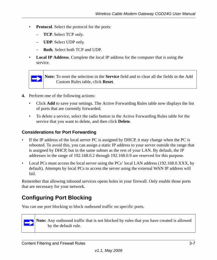
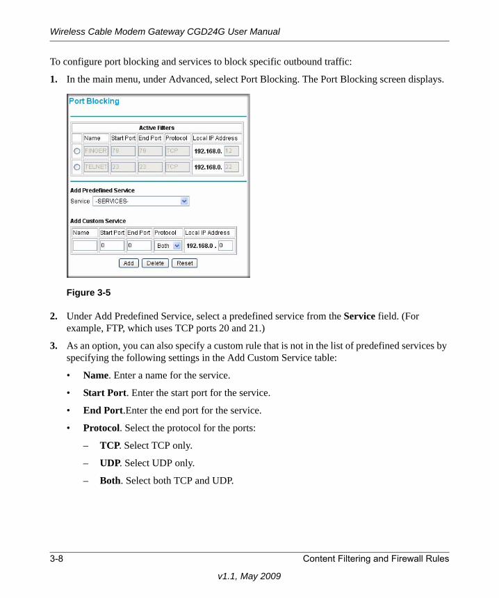
To configure port blocking and services to block specific outbound traffic:
1. In the main menu, under Advanced, select Port Blocking. The Port Blocking screen displays.
2. Under Add Predefined Service, select a predefined service from the Service field. (For example, FTP, which uses TCP ports 20 and 21.)
3. As an option, you can also specify a custom rule that is not in the list of predefined services by specifying the following settings in the Add Custom Service table:
• Name. Enter a name for the service.
• Start Port. Enter the start port for the service.
• End Port.Enter the end port for the service.
• Protocol. Select the protocol for the ports:
– TCP. Select TCP only.
– UDP. Select UDP only.
– Both. Select both TCP and UDP.
Figure 3-5
3-8 Content Filtering and Firewall Rules
v1.1, May 2009
Wireless Cable Modem Gateway CGD24G User Manual
• Local IP Address. Complete the local IP address for the computer that is using the service.
4. Perform one of the following actions:
• Click Add to save your settings. The Active Filters table now displays the list of ports that are currently forwarded.
• To delete a service, select the radio button in the Active Filters table for the service that you want to delete, and then click Delete.
Note: To reset the selection in the Service field and to clear all the fields in the Add Custom Rules table, click Reset.
Content Filtering and Firewall Rules 3-9
v1.1, May 2009

Wireless Cable Modem Gateway CGD24G User Manual
3-10 Content Filtering and Firewall Rules
v1.1, May 2009
Chapter 4Managing Your Network
This chapter describes how to perform network management tasks with your CGD24G gateway. When you log in to the gateway, these tasks are grouped under Maintenance.
This chapter includes:
• “Viewing the Gateway Status” on this page• “Viewing the Connection Status” on page 4-3• “Changing the Built-In Password” on page 4-4• “Backing Up and Restoring Your Settings” on page 4-5• “Viewing the Event Log” on page 4-6• “Running Diagnostic Utilities” on page 4-7
Log in to the gateway using its default address of http://192.168.0.1 or at whatever IP address the unit is currently configured. Use the default user name of admin and default password of password, or the password you have set up.
Viewing the Gateway Status
Use the Gateway Status screen to see hardware and firmware details about the gateway and to see basic status information. In the main menu, under Maintenance, select Gateway Status. The Gateway Status screen displays.
4-1
v1.0, November 2008
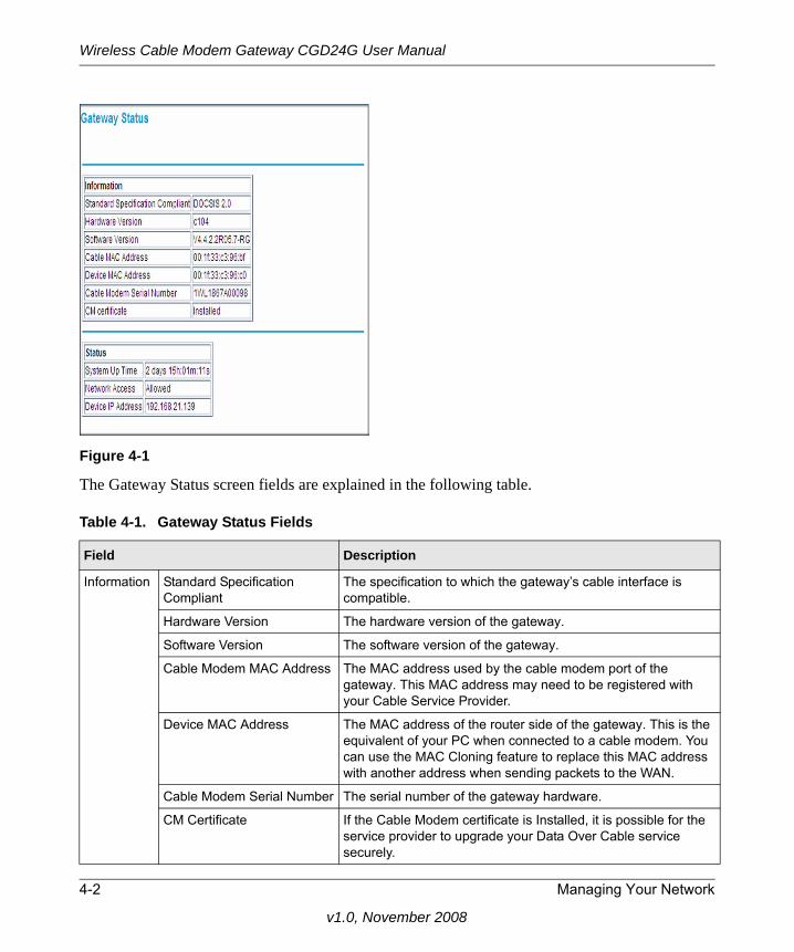
Wireless Cable Modem Gateway CGD24G User Manual
The Gateway Status screen fields are explained in the following table.
Figure 4-1
Table 4-1. Gateway Status Fields
Field Description
Information Standard Specification Compliant
The specification to which the gateway’s cable interface is compatible.
Hardware Version The hardware version of the gateway.
Software Version The software version of the gateway.
Cable Modem MAC Address The MAC address used by the cable modem port of the gateway. This MAC address may need to be registered with your Cable Service Provider.
Device MAC Address The MAC address of the router side of the gateway. This is the equivalent of your PC when connected to a cable modem. You can use the MAC Cloning feature to replace this MAC address with another address when sending packets to the WAN.
Cable Modem Serial Number The serial number of the gateway hardware.
CM Certificate If the Cable Modem certificate is Installed, it is possible for the service provider to upgrade your Data Over Cable service securely.
4-2 Managing Your Network
v1.0, November 2008
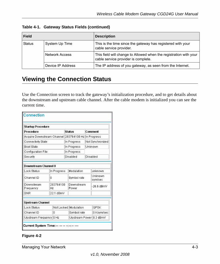
Wireless Cable Modem Gateway CGD24G User Manual
Viewing the Connection Status
Use the Connection screen to track the gateway’s initialization procedure, and to get details about the downstream and upstream cable channel. After the cable modem is initialized you can see the current time.
Status System Up Time This is the time since the gateway has registered with your cable service provider.
Network Access This field will change to Allowed when the registration with your cable service provider is complete.
Device IP Address The IP address of you gateway, as seen from the Internet.
Figure 4-2
Table 4-1. Gateway Status Fields (continued)
Field Description
Managing Your Network 4-3
v1.0, November 2008
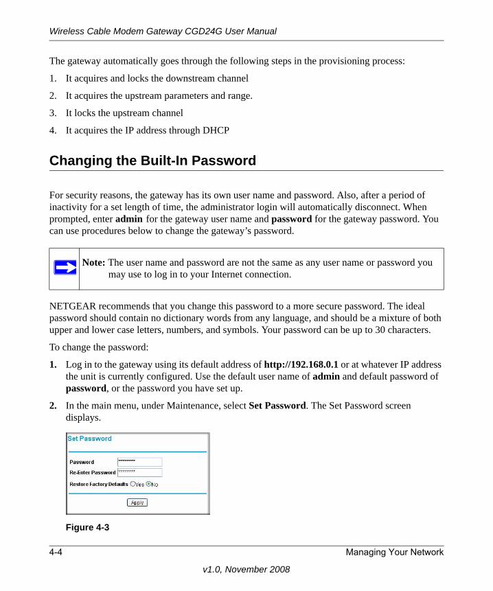
Wireless Cable Modem Gateway CGD24G User Manual
The gateway automatically goes through the following steps in the provisioning process:
1. It acquires and locks the downstream channel
2. It acquires the upstream parameters and range.
3. It locks the upstream channel
4. It acquires the IP address through DHCP
Changing the Built-In Password
For security reasons, the gateway has its own user name and password. Also, after a period of inactivity for a set length of time, the administrator login will automatically disconnect. When prompted, enter admin for the gateway user name and password for the gateway password. You can use procedures below to change the gateway’s password.
NETGEAR recommends that you change this password to a more secure password. The ideal password should contain no dictionary words from any language, and should be a mixture of both upper and lower case letters, numbers, and symbols. Your password can be up to 30 characters.
To change the password:
1. Log in to the gateway using its default address of http://192.168.0.1 or at whatever IP address the unit is currently configured. Use the default user name of admin and default password of password, or the password you have set up.
2. In the main menu, under Maintenance, select Set Password. The Set Password screen displays.
Note: The user name and password are not the same as any user name or password you may use to log in to your Internet connection.
Figure 4-3
4-4 Managing Your Network
v1.0, November 2008
Wireless Cable Modem Gateway CGD24G User Manual
3. To change the password, first enter the old password, and then enter the new password twice.
4. Click Apply to save your changes.
Resetting to Factory Default SettingsYou can erase the gateway configuration and reset it to the factory default settings. For information about the factory default settings, see “Factory Default Settings” in Appendix A. To reset the gateway to its factory settings:
1. In the Set Password screen (see Figure 4-3), to the right of Restore Factory Defaults, select the Yes radio button.
2. Click Apply to save your changes.
The gateway reboots automatically. After rebooting, the gateway’s password will be password, the LAN IP address will be 192.168.0.1, and the gateway’s DHCP client will be enabled..
Backing Up and Restoring Your Settings
The configuration settings of the gateway are stored in a configuration file in the gateway. To see the backup settings:
1. Log in to the gateway using its default address of http://192.168.0.1 or at whatever IP address the unit is currently configured. Use the default user name of admin and default password of password, or the password you have set up.
Note: After changing the password, you will be required to log in again to continue the configuration. If you have backed up the gateway settings previously, you should do a new backup so that the saved settings file includes the new password.
Note: If you do not know the login password or IP address, you can use the reset button on the rear panel of the gateway to restore the factory default settings.
Note: When erasing and resetting the configuration, do not interrupt the process by going on online, turning off the gateway, or shutting down the computer.
Managing Your Network 4-5
v1.0, November 2008
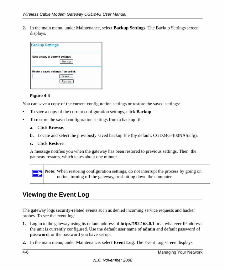
Wireless Cable Modem Gateway CGD24G User Manual
2. In the main menu, under Maintenance, select Backup Settings. The Backup Settings screen displays.
You can save a copy of the current configuration settings or restore the saved settings:
• To save a copy of the current configuration settings, click Backup.
• To restore the saved configuration settings from a backup file:
a. Click Browse.
b. Locate and select the previously saved backup file (by default, CGD24G-100NAS.cfg).
c. Click Restore.
A message notifies you when the gateway has been restored to previous settings. Then, the gateway restarts, which takes about one minute.
Viewing the Event Log
The gateway logs security-related events such as denied incoming service requests and hacker probes. To see the event log:
1. Log in to the gateway using its default address of http://192.168.0.1 or at whatever IP address the unit is currently configured. Use the default user name of admin and default password of password, or the password you have set up.
2. In the main menu, under Maintenance, select Event Log. The Event Log screen displays.
Figure 4-4
Note: When restoring configuration settings, do not interrupt the process by going on online, turning off the gateway, or shutting down the computer.
4-6 Managing Your Network
v1.0, November 2008
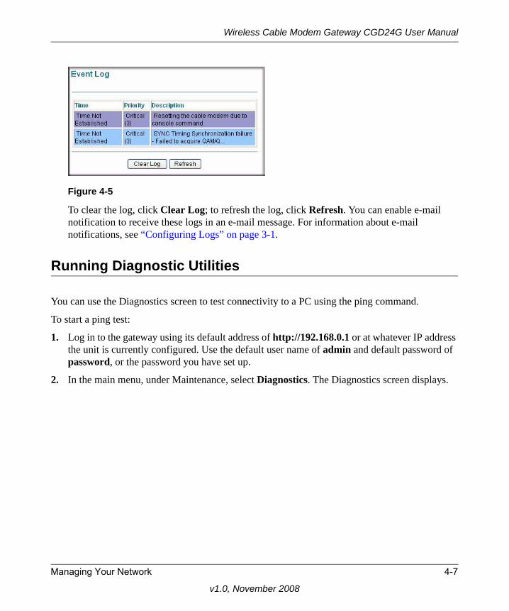
Wireless Cable Modem Gateway CGD24G User Manual
To clear the log, click Clear Log; to refresh the log, click Refresh. You can enable e-mail notification to receive these logs in an e-mail message. For information about e-mail notifications, see “Configuring Logs” on page 3-1.
Running Diagnostic Utilities
You can use the Diagnostics screen to test connectivity to a PC using the ping command.
To start a ping test:
1. Log in to the gateway using its default address of http://192.168.0.1 or at whatever IP address the unit is currently configured. Use the default user name of admin and default password of password, or the password you have set up.
2. In the main menu, under Maintenance, select Diagnostics. The Diagnostics screen displays.
Figure 4-5
Managing Your Network 4-7
v1.0, November 2008
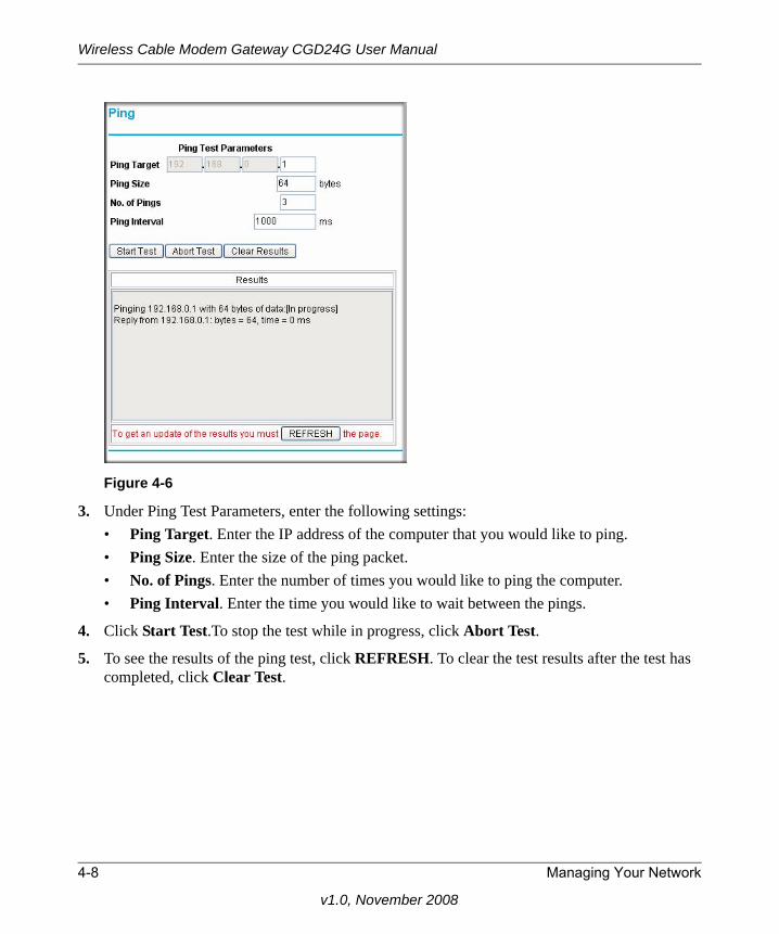
Wireless Cable Modem Gateway CGD24G User Manual
3. Under Ping Test Parameters, enter the following settings:• Ping Target. Enter the IP address of the computer that you would like to ping.• Ping Size. Enter the size of the ping packet.• No. of Pings. Enter the number of times you would like to ping the computer.• Ping Interval. Enter the time you would like to wait between the pings.
4. Click Start Test.To stop the test while in progress, click Abort Test.
5. To see the results of the ping test, click REFRESH. To clear the test results after the test has completed, click Clear Test.
Figure 4-6
4-8 Managing Your Network
v1.0, November 2008
Wireless Cable Modem Gateway CGD24G User Manual
Chapter 5Customizing Your Network
This chapter describes how to customize your network through the advanced settings on your CGD24G gateway. When you log in to the gateway, these tasks are grouped under Advanced.
This chapter includes:
• “Configuring Dynamic DNS” on this page• “Restricting Access by MAC Address” on page 5-2• “Configuring Port Triggering” on page 5-4• “Setting Up a DMZ Host” on page 5-6• “LAN IP Settings” on page 5-7• “Enabling Remote Management” on page 5-9• “Configuring Universal Plug and Play (UPnP)” on page 5-11
Log in to the gateway using its default address of http://192.168.0.1 or at whatever IP address the unit is currently configured. Use the default user name of admin and default password of password, or the password you have set up.
Configuring Dynamic DNS
A dynamic DNS service provides a central public database where information (such as e-mail addresses, host names and IP addresses) can be stored and retrieved. The dynamic DNS server also stores password-protected information and accepts queries based on e-mail addresses.
If you want to use a dynamic DNS service, you must register for it. The dynamic DNS client service provider will give you a password or key.
Note: For information about port forwarding and port blocking, see“Firewall Rules—Port Forwarding and Port Blocking” on page 3-5.
Customizing Your Network 5-1
v1.1, May 2009
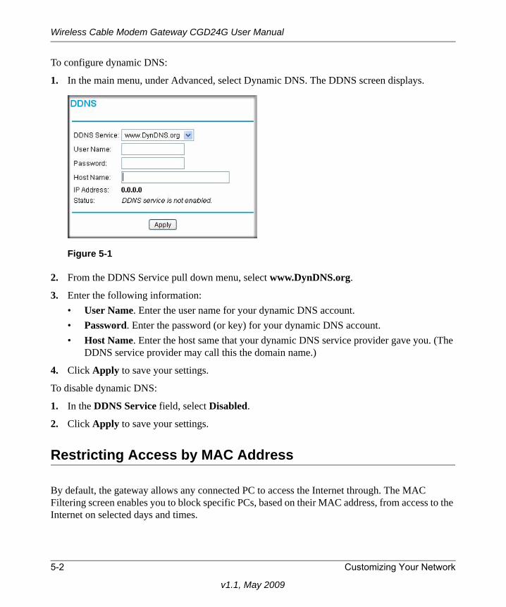
Wireless Cable Modem Gateway CGD24G User Manual
To configure dynamic DNS:
1. In the main menu, under Advanced, select Dynamic DNS. The DDNS screen displays.
2. From the DDNS Service pull down menu, select www.DynDNS.org.
3. Enter the following information:• User Name. Enter the user name for your dynamic DNS account.• Password. Enter the password (or key) for your dynamic DNS account.• Host Name. Enter the host same that your dynamic DNS service provider gave you. (The
DDNS service provider may call this the domain name.)
4. Click Apply to save your settings.
To disable dynamic DNS:
1. In the DDNS Service field, select Disabled.
2. Click Apply to save your settings.
Restricting Access by MAC Address
By default, the gateway allows any connected PC to access the Internet through. The MAC Filtering screen enables you to block specific PCs, based on their MAC address, from access to the Internet on selected days and times.
Figure 5-1
5-2 Customizing Your Network
v1.1, May 2009
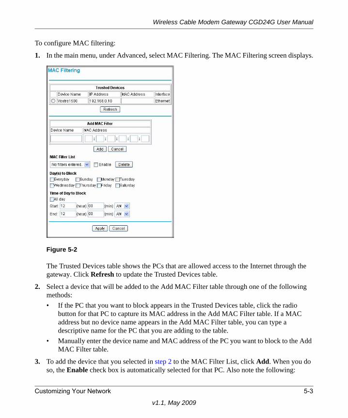
Wireless Cable Modem Gateway CGD24G User Manual
To configure MAC filtering:
1. In the main menu, under Advanced, select MAC Filtering. The MAC Filtering screen displays.
The Trusted Devices table shows the PCs that are allowed access to the Internet through the gateway. Click Refresh to update the Trusted Devices table.
2. Select a device that will be added to the Add MAC Filter table through one of the following methods:• If the PC that you want to block appears in the Trusted Devices table, click the radio
button for that PC to capture its MAC address in the Add MAC Filter table. If a MAC address but no device name appears in the Add MAC Filter table, you can type a descriptive name for the PC that you are adding to the table.
• Manually enter the device name and MAC address of the PC you want to block to the Add MAC Filter table.
3. To add the device that you selected in step 2 to the MAC Filter List, click Add. When you do so, the Enable check box is automatically selected for that PC. Also note the following:
Figure 5-2
Customizing Your Network 5-3
v1.1, May 2009
Wireless Cable Modem Gateway CGD24G User Manual
• To deselect a PC from the MAC Filter List, select the PC from the drop-down list, and then clear its Enable check box. Doing so leaves the PC in the MAC Filter List but ensures that the PC is not blocked.
• To remove a PC from the MAC Filter List, select the PC from the drop-down list, and then click Delete.
4. Select the days and times that a selected PC will be blocked:
a. Day(s) to Block. Select the days on which the PC that is selected in the MAC Filter List will be blocked. The default is Everyday.
b. Time of Day to Block. Select a start time and an end time to specify a period during which the PC that is selected in the MAC Filter List will be blocked. The default is All Day. Be sure that you deselect the All Day check box if you want to enter specific times. The selected period applies to each day that you selected in the previous step.
5. Click Add to save your settings.
6. Repeat step 2 through step 5 for all PCs that you want to block.
Configuring Port Triggering
Port triggering is an advanced feature that can be used to easily enable gaming and other Internet applications that would otherwise be blocked by the firewall. Using this feature requires that you know the port numbers that are used by the application.
Port triggering is an advanced feature that can be used to easily enable gaming and other Internet applications that would otherwise be blocked by the firewall. Using this feature requires that you know the port numbers that are used by the application.
Once configured, port triggering operation is as follows:
1. A PC makes an outgoing connection using a port number defined in the Port Triggering table.
2. The gateway records this connection, opens the incoming port or ports associated with this entry in the Port Triggering List, and associates them with the PC.
3. The remote system receives the PCs request, and responds using a different port number.
Note: For information about port forwarding and port blocking, see“Firewall Rules—Port Forwarding and Port Blocking” on page 3-5.
5-4 Customizing Your Network
v1.1, May 2009
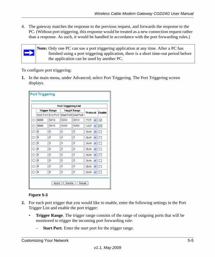
Wireless Cable Modem Gateway CGD24G User Manual
4. The gateway matches the response to the previous request, and forwards the response to the PC. (Without port triggering, this response would be treated as a new connection request rather than a response. As such, it would be handled in accordance with the port forwarding rules.)
To configure port triggering:
1. In the main menu, under Advanced, select Port Triggering. The Port Triggering screen displays.
2. For each port trigger that you would like to enable, enter the following settings in the Port Trigger List and enable the port trigger:
• Trigger Range. The trigger range consists of the range of outgoing ports that will be monitored to trigger the incoming port forwarding rule:
– Start Port. Enter the start port for the trigger range.
Note: Only one PC can use a port triggering application at any time. After a PC has finished using a port triggering application, there is a short time-out period before the application can be used by another PC.
Figure 5-3
Customizing Your Network 5-5
v1.1, May 2009
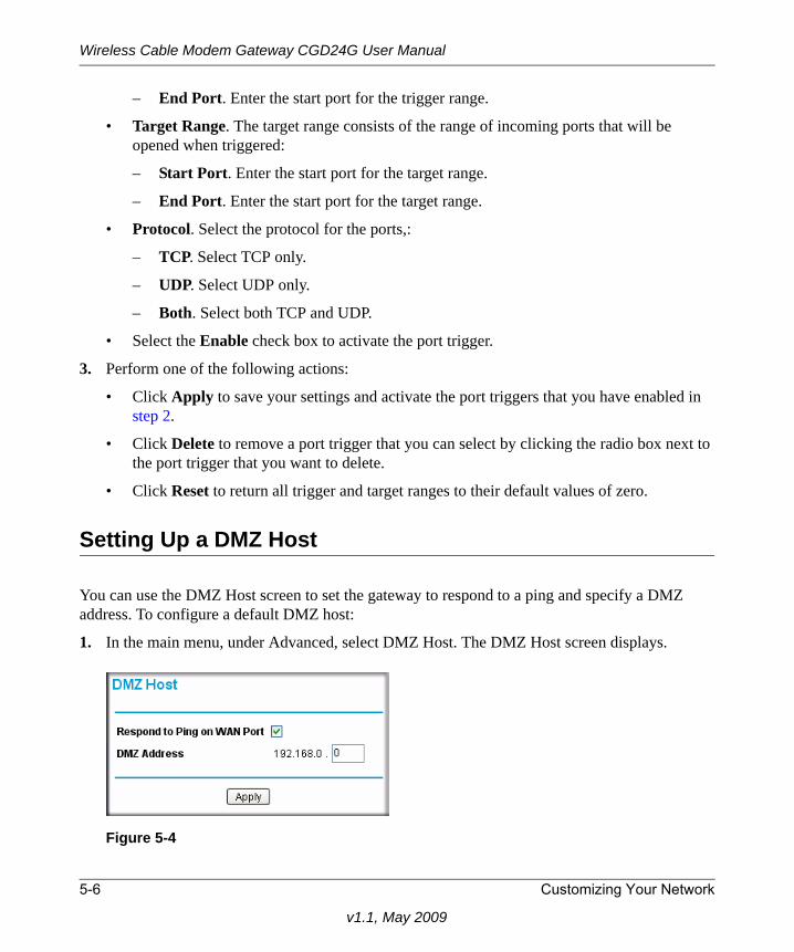
Wireless Cable Modem Gateway CGD24G User Manual
– End Port. Enter the start port for the trigger range.
• Target Range. The target range consists of the range of incoming ports that will be opened when triggered:
– Start Port. Enter the start port for the target range.
– End Port. Enter the start port for the target range.
• Protocol. Select the protocol for the ports,:
– TCP. Select TCP only.
– UDP. Select UDP only.
– Both. Select both TCP and UDP.
• Select the Enable check box to activate the port trigger.
3. Perform one of the following actions:
• Click Apply to save your settings and activate the port triggers that you have enabled in step 2.
• Click Delete to remove a port trigger that you can select by clicking the radio box next to the port trigger that you want to delete.
• Click Reset to return all trigger and target ranges to their default values of zero.
Setting Up a DMZ Host
You can use the DMZ Host screen to set the gateway to respond to a ping and specify a DMZ address. To configure a default DMZ host:
1. In the main menu, under Advanced, select DMZ Host. The DMZ Host screen displays.
Figure 5-4
5-6 Customizing Your Network
v1.1, May 2009
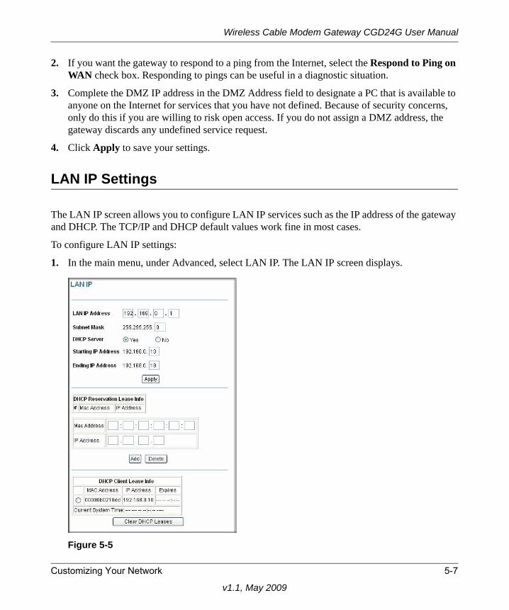
Wireless Cable Modem Gateway CGD24G User Manual
2. If you want the gateway to respond to a ping from the Internet, select the Respond to Ping on WAN check box. Responding to pings can be useful in a diagnostic situation.
3. Complete the DMZ IP address in the DMZ Address field to designate a PC that is available to anyone on the Internet for services that you have not defined. Because of security concerns, only do this if you are willing to risk open access. If you do not assign a DMZ address, the gateway discards any undefined service request.
4. Click Apply to save your settings.
LAN IP Settings
The LAN IP screen allows you to configure LAN IP services such as the IP address of the gateway and DHCP. The TCP/IP and DHCP default values work fine in most cases.
To configure LAN IP settings:
1. In the main menu, under Advanced, select LAN IP. The LAN IP screen displays.
Figure 5-5
Customizing Your Network 5-7
v1.1, May 2009
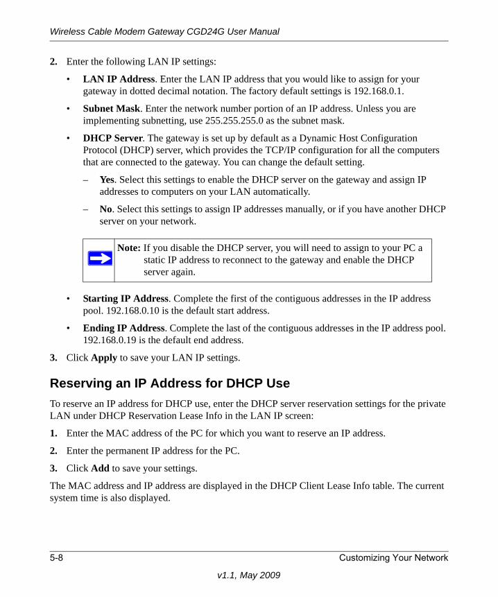
Wireless Cable Modem Gateway CGD24G User Manual
2. Enter the following LAN IP settings:
• LAN IP Address. Enter the LAN IP address that you would like to assign for your gateway in dotted decimal notation. The factory default settings is 192.168.0.1.
• Subnet Mask. Enter the network number portion of an IP address. Unless you are implementing subnetting, use 255.255.255.0 as the subnet mask.
• DHCP Server. The gateway is set up by default as a Dynamic Host Configuration Protocol (DHCP) server, which provides the TCP/IP configuration for all the computers that are connected to the gateway. You can change the default setting.
– Yes. Select this settings to enable the DHCP server on the gateway and assign IP addresses to computers on your LAN automatically.
– No. Select this settings to assign IP addresses manually, or if you have another DHCP server on your network.
• Starting IP Address. Complete the first of the contiguous addresses in the IP address pool. 192.168.0.10 is the default start address.
• Ending IP Address. Complete the last of the contiguous addresses in the IP address pool. 192.168.0.19 is the default end address.
3. Click Apply to save your LAN IP settings.
Reserving an IP Address for DHCP UseTo reserve an IP address for DHCP use, enter the DHCP server reservation settings for the private LAN under DHCP Reservation Lease Info in the LAN IP screen:
1. Enter the MAC address of the PC for which you want to reserve an IP address.
2. Enter the permanent IP address for the PC.
3. Click Add to save your settings.
The MAC address and IP address are displayed in the DHCP Client Lease Info table. The current system time is also displayed.
Note: If you disable the DHCP server, you will need to assign to your PC a static IP address to reconnect to the gateway and enable the DHCP server again.
5-8 Customizing Your Network
v1.1, May 2009
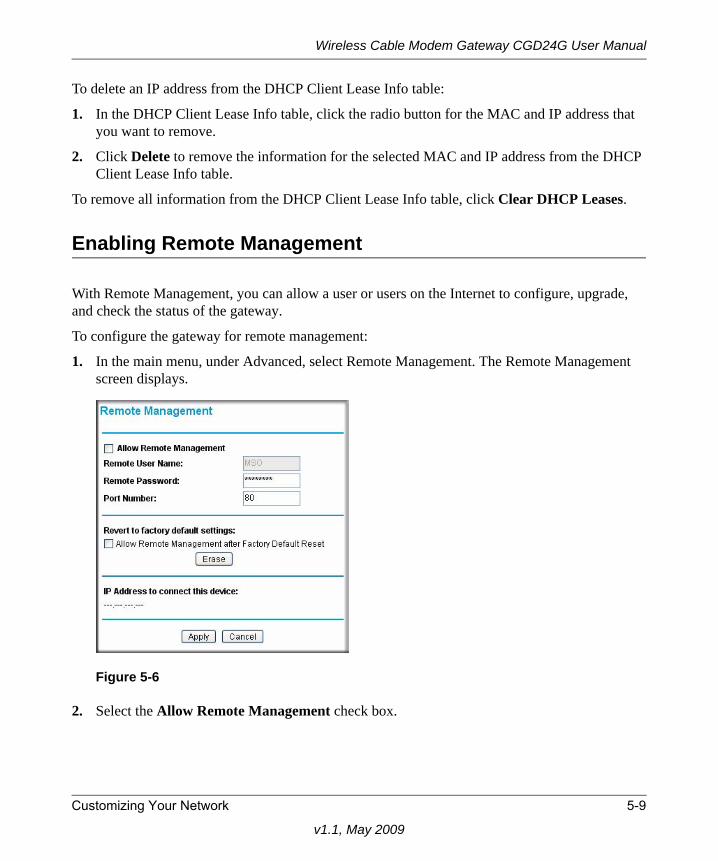
Wireless Cable Modem Gateway CGD24G User Manual
To delete an IP address from the DHCP Client Lease Info table:
1. In the DHCP Client Lease Info table, click the radio button for the MAC and IP address that you want to remove.
2. Click Delete to remove the information for the selected MAC and IP address from the DHCP Client Lease Info table.
To remove all information from the DHCP Client Lease Info table, click Clear DHCP Leases.
Enabling Remote Management
With Remote Management, you can allow a user or users on the Internet to configure, upgrade, and check the status of the gateway.
To configure the gateway for remote management:
1. In the main menu, under Advanced, select Remote Management. The Remote Management screen displays.
2. Select the Allow Remote Management check box.
Figure 5-6
Customizing Your Network 5-9
v1.1, May 2009
Wireless Cable Modem Gateway CGD24G User Manual
3. Enter the following information:
• Remote Password. Enter the user name that will be used from the remote PC to manage the gateway. This password is different from the password that you use to log into the gateway from your LAN.
• Port Number. Specify the port number that will be used for accessing the management interface. The default port number is 80.
4. Click Apply to save your changes.
Reverting to Factory Default SettingIf you would like to erase settings but continue to allow access from the WAN after the settings have been erased, select the Allow Remote Management after Factory Default Reset check box under “Revert to factory default settings” in the Remote Management screen. Then, click Erase.
Note: Be sure to change the gateway’s remote management password to a very secure password before enabling remote management. The ideal password should contain no dictionary words from any language, and should be a mixture of letters (both upper and lower case), numbers, and symbols. Your password can be up to 16 characters.
Note: Web browser access normally uses the standard HTTP service port 80. For greater security, you can change the remote management Web interface to a custom port by entering that number in the box provided. Choose a number between 1024 and 65535, but do not use the number of any common service port. The default is 8080, which is a common alternate for HTTP.
Note: Do not attempt to go online, turn off the gateway, shut down the computer, or do anything else to the gateway until the gateway finishes restarting. When the test light turns off, wait a few more seconds before you do anything with the gateway.After you have erased the gateway’s current settings, the gateway’s password will be password, the LAN IP address will be 192.168.0.1, the gateway will function as a DHCP server on the LAN, and the gateway will function as a DHCP client to the Internet.
5-10 Customizing Your Network
v1.1, May 2009
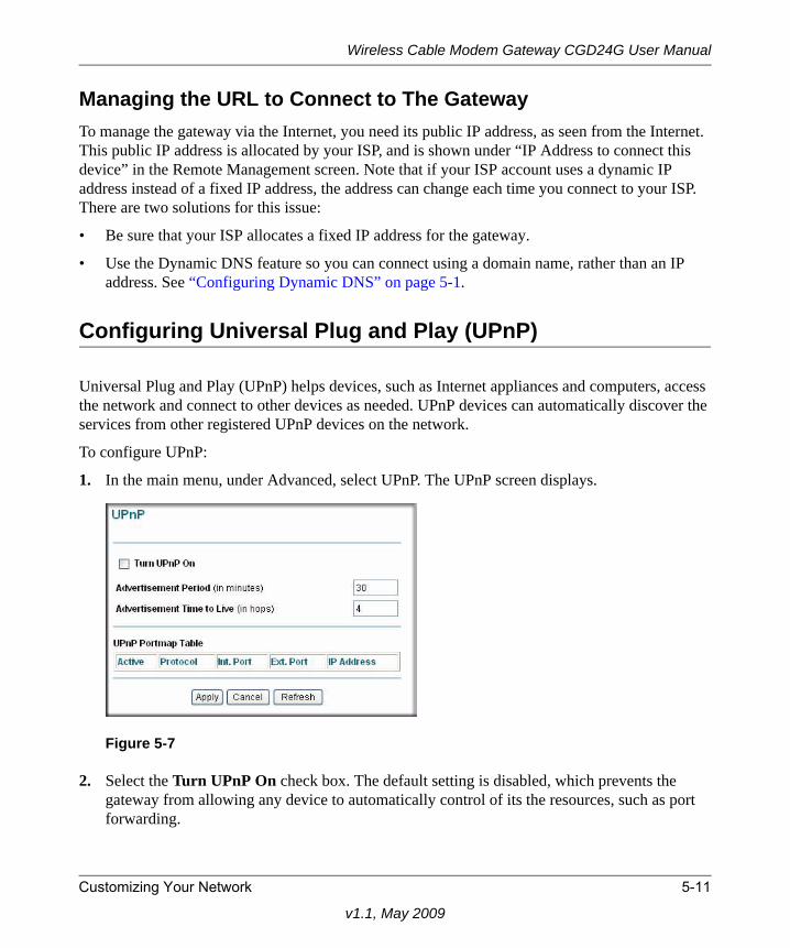
Wireless Cable Modem Gateway CGD24G User Manual
Managing the URL to Connect to The GatewayTo manage the gateway via the Internet, you need its public IP address, as seen from the Internet. This public IP address is allocated by your ISP, and is shown under “IP Address to connect this device” in the Remote Management screen. Note that if your ISP account uses a dynamic IP address instead of a fixed IP address, the address can change each time you connect to your ISP. There are two solutions for this issue:
• Be sure that your ISP allocates a fixed IP address for the gateway.
• Use the Dynamic DNS feature so you can connect using a domain name, rather than an IP address. See “Configuring Dynamic DNS” on page 5-1.
Configuring Universal Plug and Play (UPnP)
Universal Plug and Play (UPnP) helps devices, such as Internet appliances and computers, access the network and connect to other devices as needed. UPnP devices can automatically discover the services from other registered UPnP devices on the network.
To configure UPnP:
1. In the main menu, under Advanced, select UPnP. The UPnP screen displays.
2. Select the Turn UPnP On check box. The default setting is disabled, which prevents the gateway from allowing any device to automatically control of its the resources, such as port forwarding.
Figure 5-7
Customizing Your Network 5-11
v1.1, May 2009
Wireless Cable Modem Gateway CGD24G User Manual
3. Enter the following information:
• Advertisement Period. Enter how often the gateway broadcasts its UPnP information. The default is 30 minutes.Shorter durations will ensure that control points have current device status at the expense of additional network traffic. Longer durations may compromise the freshness of the device status but can significantly reduce network traffic.
• Advertisement Time to Live. Enter the time to live for the advertisement, which is measured in hops (steps) for each UPnP packet that is sent. A hop is the number of steps that are allowed to propagate for each UPnP advertisement before it disappears. The number of hops can range from 1 to 255. The default value for the advertisement time to live is 4 hops, which should be fine for most home networks. If you notice that some devices are not being updated or reached correctly, you might need to increase this value slightly.
The UPnP Portmap Table displays the IP address of each UPnP device that is currently accessing the router and which internal and external ports of the gateway were opened by that device. The UPnP Portmap Table also displays the protocol for the port that was opened and if that port is still active for each IP address.
4. Perform one of the following actions:
• Click Apply to save your settings.
• Click Cancel to disregard any unsaved changes.
• Click Refresh to update the UPnP Portmap Table and to show the active ports that are currently opened by UPnP devices.
5-12 Customizing Your Network
v1.1, May 2009
Chapter 6Troubleshooting
This chapter gives information about troubleshooting your CGD24G Wireless Cable Modem Gateway. For the common problems listed, go to the section indicated.
• Have I connected the gateway correctly?
Go to “Basic Functions” on page 6-1.
• I cannot access the gateway configuration with my browser.
Go to “Connecting to the Gateway’s Main Menu” on page 6-3.
• I have configured the gateway but I cannot access the Internet.
Go to “Troubleshooting the ISP Connection” on page 6-4.
• I cannot remember the gateway’s configuration password or I want to clear the configuration and start over again.
Go to “Backing Up and Restoring Your Settings” on page 4-5.
Basic Functions
After you have turned on power to the gateway, you should do the following:
1. When power is first applied, verify that the Power LED is on.
2. Verify that the numbered Ethernet LEDs come on momentarily.
3. After a few seconds, verify that the Local port Link LEDs are lit for any local ports that are connected.
If any of these conditions does not occur, refer to the appropriate following section.
Tip: NETGEAR provides helpful articles, documentation, and the latest software updates at http://www.netgear.com/support.
6-1
v1.1, May 2009
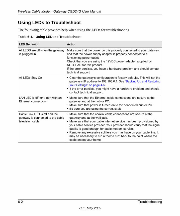
Wireless Cable Modem Gateway CGD24G User Manual
Using LEDs to TroubleshootThe following table provides help when using the LEDs for troubleshooting.
Table 6-1. Using LEDs to Troubleshoot
LED Behavior Action
All LEDS are off when the gateway is plugged in.
Make sure that the power cord is properly connected to your gateway and that the power supply adapter is properly connected to a functioning power outlet. Check that you are using the 12VDC power adapter supplied by NETGEAR for this product.If the error persists, you have a hardware problem and should contact technical support.
All LEDs Stay On • Clear the gateway’s configuration to factory defaults. This will set the gateway’s IP address to 192.168.0.1. See “Backing Up and Restoring Your Settings” on page 4-5.
• If the error persists, you might have a hardware problem and should contact technical support.
LAN LED is off for a port with an Ethernet connection.
• Make sure that the Ethernet cable connections are secure at the gateway and at the hub or PC.
• Make sure that power is turned on to the connected hub or PC.• Be sure you are using the correct cable.
Cable Link LED is off and the gateway is connected to the cable television cable.
• Make sure that the coaxial cable connections are secure at the gateway and at the wall jack.
• Make sure that your cable internet service has been provisioned by your cable service provider. Your provider should verify that the signal quality is good enough for cable modem service.
• Remove any excessive splitters you may have on your cable line. It may be necessary to run a “home run” back to the point where the cable enters your home.
6-2 Troubleshooting
v1.1, May 2009
Wireless Cable Modem Gateway CGD24G User Manual
Connecting to the Gateway’s Main Menu
If you are unable to access the gateway’s main menu from a computer on your local network, check the following:
• Check the Ethernet connection between the computer and the gateway as described in the previous section.
• Make sure that your PC’s IP address is on the same subnet as the gateway. If you are using the recommended addressing scheme, your PC’s address should be in the range of 192.168.0.10 to 192.168.0.254. Refer to the link to the online document “ITCP/IP Networking Basics” in Appendix B for help configuring your computer.
• If your gateway’s IP address has been changed and you don’t know the current IP address, clear the gateway’s configuration to factory defaults. This will set the gateway’s IP address to 192.168.0.1. This procedure is explained in “Enabling Remote Management” on page 5-9.
• Make sure your browser has Java, JavaScript, or ActiveX enabled. If you are using Internet Explorer, click Refresh to make sure that the Java applet is loaded.
• Try quitting the browser and launching it again.
• Make sure you are using the correct login information. The gateway has two user names both lower-case (Caps Lock should be off):
– The superuser login name is mso with the default password of changeme.
– The other login name is admin with the default password of password.
If the gateway does not save changes you have made, check the following:
• When entering configuration settings, be sure to click the Apply button before moving to another screen, or your changes are lost.
• Click the Refresh or Reload button in the Web browser. The changes may have occurred, but the Web browser may be caching the old configuration.
Note: If your PC’s IP address is shown as 169.254.x.x:Recent versions of Windows and MacOS will generate and assign an IP address if the computer cannot reach a DHCP server. These auto-generated addresses are in the range of 169.254.x.x. If your IP address is in this range, check the connection from the PC to the gateway and reboot your PC.
Troubleshooting 6-3
v1.1, May 2009
Wireless Cable Modem Gateway CGD24G User Manual
Troubleshooting the ISP Connection
If your gateway is unable to access the Internet and your Cable Link LED is on, you may need to register the Cable MAC Address and/or Device MAC Address of you gateway with your cable service provider. This is described in “Connecting the Gateway” on page 1-5.
Additionally, your PC may not have the gateway configured as its TCP/IP gateway. If your PC obtains its information from the gateway by DHCP, reboot the PC and verify the gateway address. See the link to the online document “ITCP/IP Networking Basics” in Appendix B.
Troubleshooting a TCP/IP Network Using a Ping Utility
Most TCP/IP terminal devices and routers contain a ping utility that sends an echo request packet to the designated device. The device then responds with an echo reply. Troubleshooting a TCP/IP network is made easier by using the ping utility in your PC or workstation.
Testing the LAN Path to Your GatewayYou can use ping to verify that the LAN path to your gateway is set up correctly.
To ping the gateway from a PC running Windows 95 or later:
1. From the Windows toolbar, click on the Start button and select Run.
2. In the field provided, type Ping followed by the IP address of the gateway, as in this example:
ping 192.168.0.1
3. Click OK.
You should see a message like this one:Pinging <IP address> with 32 bytes of data
If the path is working, you see this message:Reply from < IP address >: bytes=32 time=NN ms TTL=xxx
If the path is not working, you see this message:Request timed out
6-4 Troubleshooting
v1.1, May 2009
Wireless Cable Modem Gateway CGD24G User Manual
If the path is not working correctly, you could have one of the following problems:
• Wrong physical connections.
– Make sure the LAN port LED is on. If the LED is off, see “Using LEDs to Troubleshoot” on page 6-2.
– Check that the corresponding Link LEDs are on for your network interface card and for the hub ports (if any) that are connected to your workstation and gateway.
• Wrong network configuration.
– Verify that the Ethernet card driver software and TCP/IP software are both installed and configured on your PC or workstation.
– Verify that the IP address for your gateway and your workstation are correct and that the addresses are on the same subnet.
Testing the Path from Your PC to a Remote DeviceAfter verifying that the LAN path works correctly, test the path from your PC to a remote device. From the Windows run menu, type:
PING -n 10 <IP address>
where <IP address> is the IP address of a remote device such as your ISP’s DNS server.
If the path is functioning correctly, replies as in the previous section are displayed. If you do not receive replies:
• Check that your PC has the IP address of your gateway listed as the default gateway. If the IP configuration of your PC is assigned by DHCP, this information will not be visible in your PC’s Network Control Panel. Verify that the IP address of the gateway is listed as the default gateway. See the link to the online document “ITCP/IP Networking Basics” in Appendix B.
• Check to see that the network address of your PC (the portion of the IP address specified by the netmask) is different from the network address of the remote device.
• Check that your Cable Link LED is on.
• If your ISP assigned a host name to your PC, enter that host name as the Account Name in the Basic Settings menu.
Troubleshooting 6-5
v1.1, May 2009
Wireless Cable Modem Gateway CGD24G User Manual
6-6 Troubleshooting
v1.1, May 2009
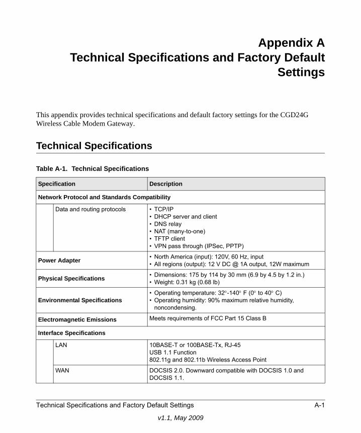
Appendix ATechnical Specifications and Factory Default
Settings
This appendix provides technical specifications and default factory settings for the CGD24G Wireless Cable Modem Gateway.
Technical Specifications
Table A-1. Technical Specifications
Specification Description
Network Protocol and Standards Compatibility
Data and routing protocols • TCP/IP• DHCP server and client• DNS relay• NAT (many-to-one)• TFTP client• VPN pass through (IPSec, PPTP)
Power Adapter • North America (input): 120V, 60 Hz, input• All regions (output): 12 V DC @ 1A output, 12W maximum
Physical Specifications • Dimensions: 175 by 114 by 30 mm (6.9 by 4.5 by 1.2 in.)• Weight: 0.31 kg (0.68 lb)
Environmental Specifications• Operating temperature: 32°-140° F (0° to 40° C)• Operating humidity: 90% maximum relative humidity,
noncondensing.
Electromagnetic Emissions Meets requirements of FCC Part 15 Class B
Interface Specifications
LAN 10BASE-T or 100BASE-Tx, RJ-45USB 1.1 Function802.11g and 802.11b Wireless Access Point
WAN DOCSIS 2.0. Downward compatible with DOCSIS 1.0 andDOCSIS 1.1.
Technical Specifications and Factory Default Settings A-1
v1.1, May 2009
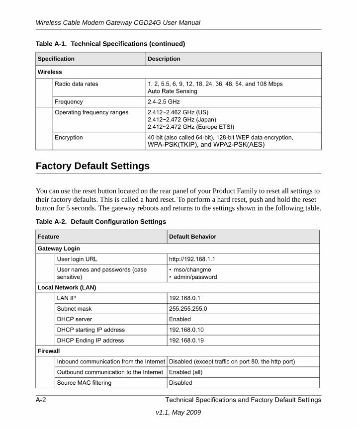
Wireless Cable Modem Gateway CGD24G User Manual
Factory Default Settings
You can use the reset button located on the rear panel of your Product Family to reset all settings to their factory defaults. This is called a hard reset. To perform a hard reset, push and hold the reset button for 5 seconds. The gateway reboots and returns to the settings shown in the following table.
Wireless
Radio data rates 1, 2, 5.5, 6, 9, 12, 18, 24, 36, 48, 54, and 108 Mbps Auto Rate Sensing
Frequency 2.4-2.5 GHz
Operating frequency ranges 2.412~2.462 GHz (US)2.412~2.472 GHz (Japan)2.412~2.472 GHz (Europe ETSI)
Encryption 40-bit (also called 64-bit), 128-bit WEP data encryption, WPA-PSK(TKIP), and WPA2-PSK(AES)
Table A-2. Default Configuration Settings
Feature Default Behavior
Gateway Login
User login URL http://192.168.1.1
User names and passwords (case sensitive)
• mso/changme• admin/password
Local Network (LAN)
LAN IP 192.168.0.1
Subnet mask 255.255.255.0
DHCP server Enabled
DHCP starting IP address 192.168.0.10
DHCP Ending IP address 192.168.0.19
Firewall
Inbound communication from the Internet Disabled (except traffic on port 80, the http port)
Outbound communication to the Internet Enabled (all)
Source MAC filtering Disabled
Table A-1. Technical Specifications (continued)
Specification Description
A-2 Technical Specifications and Factory Default Settings
v1.1, May 2009
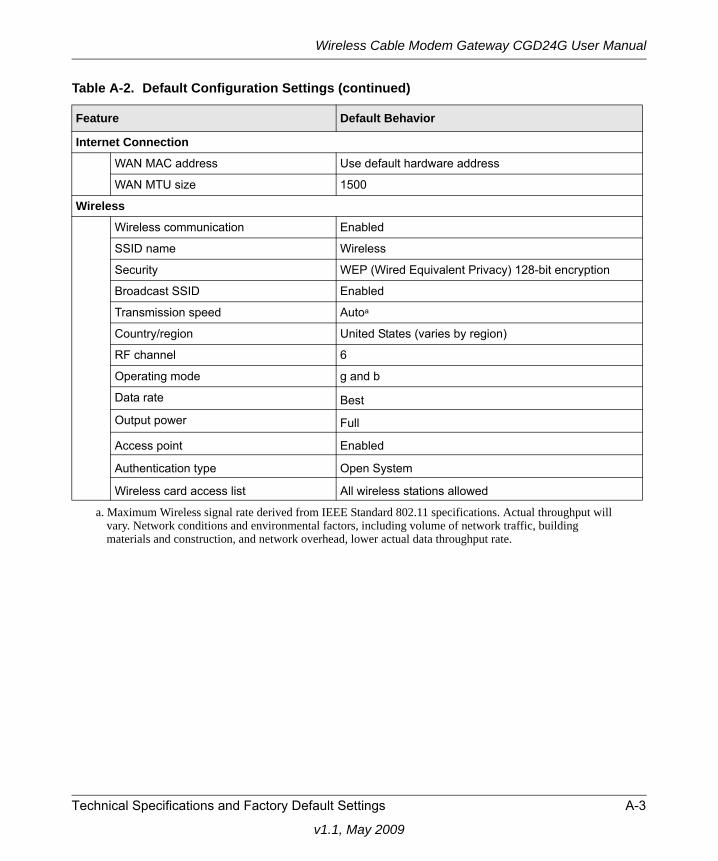
Wireless Cable Modem Gateway CGD24G User Manual
Internet Connection
WAN MAC address Use default hardware address
WAN MTU size 1500
Wireless
Wireless communication Enabled
SSID name Wireless
Security WEP (Wired Equivalent Privacy) 128-bit encryption
Broadcast SSID Enabled
Transmission speed Autoa
Country/region United States (varies by region)
RF channel 6
Operating mode g and b
Data rate BestOutput power Full
Access point Enabled
Authentication type Open System
Wireless card access list All wireless stations allowed
a. Maximum Wireless signal rate derived from IEEE Standard 802.11 specifications. Actual throughput will vary. Network conditions and environmental factors, including volume of network traffic, building materials and construction, and network overhead, lower actual data throughput rate.
Table A-2. Default Configuration Settings (continued)
Feature Default Behavior
Technical Specifications and Factory Default Settings A-3
v1.1, May 2009
Wireless Cable Modem Gateway CGD24G User Manual
A-4 Technical Specifications and Factory Default Settings
v1.1, May 2009
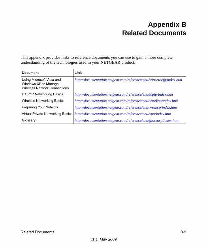
Appendix BRelated Documents
This appendix provides links to reference documents you can use to gain a more complete understanding of the technologies used in your NETGEAR product.
Document Link
Using Microsoft Vista and Windows XP to Manage Wireless Network Connections
http://documentation.netgear.com/reference/enu/winzerocfg/index.htm
ITCP/IP Networking Basics http://documentation.netgear.com/reference/enu/tcpip/index.htm
Wireless Networking Basics http://documentation.netgear.com/reference/enu/wireless/index.htmPreparing Your Network http://documentation.netgear.com/reference/enu/wsdhcp/index.htmVirtual Private Networking Basics http://documentation.netgear.com/reference/enu/vpn/index.htm
Glossary http://documentation.netgear.com/reference/enu/glossary/index.htm
Related Documents B-5
v1.1, May 2009
Wireless Cable Modem Gateway CGD24G User Manual
B-6 Related Documents
v1.1, May 2009
Index
Bbacking up the configuration file 4-5blocking
keywords 3-2PCs based on MAC address 5-5ports 3-5, 3-8services 3-5sites 3-2
Ccable channel 4-3cable line splitter 1-5cable network settings 1-9Cat5 cable 1-4coaxial cable 1-5configuration
backup 4-5erasing 4-6factory default 4-5, 5-13
connected wireless devicesadding to 2-22list of 2-22
crossover cable 5-2
Ddefault gateway 1-10, 1-12Denial of Service (DoS) 3-1DHCP 1-9
reserved IP address 5-11server 5-11
diagnostics 4-7DMZ host 5-9DNS
v1.1, Ma
dynamic service 5-1primary server 1-10secondary server 1-10
Ee-mailing logs 3-1Erase configuration 4-6Ethernet cable 1-5
Ffactory default settings 4-5, 5-13, A-2firewall rules 3-5front panel 1-2
Ggateway
backup 4-5diagnostics 4-7event log 4-6factory default settings 4-5, 5-13, A-2initialization procedure 4-3main menu 5-3password 4-4remote management 5-12status 4-1technical specifications A-1
grounding the cable distribution system 1-5
IIP addresses, auto-generated 5-3
LL2TP
Index-1
y 2009
Wireless Cable Modem Gateway CGD24G User Manual
connection 1-11, 1-12server 1-11
LANIP address 5-11IP settings 5-10
LEDsdescription 1-2troubleshooting 5-2
MMAC address 4-2
location of 2-22restrict access based on MAC address 2-21
MAC filtering 5-5MD5 authentication 5-3
Ooutbound rules 3-4, 3-5
Ppackage contents 1-1passphrase 2-7password 4-4ping utility 5-4placement of the gateway 2-1port blocking 3-4, 3-5, 3-8port forwarding 3-5, 3-7port triggering 5-7primary DNS server 1-10Push 'N' Connect 2-10
Rrear panel 1-3remote management 5-12reset button A-2restrict wireless access by MAC address 2-21router log 3-1Routing Information Protocol (RIP) 5-3
rulesinbound 3-5outbound 3-4, 3-5
Ssecondary DNS server 1-10security options 2-5, 2-6side panel 1-3SSID 2-5Static IP address 1-10static IP address 1-10, 1-12static IP mask 1-10, 1-12
TTCP/IP
network, troubleshooting 5-4technical specifications A-1troubleshooting 5-1
ISP connection 5-4LEDs 5-2ping utility 5-4TCP/IP network 5-4
UUniversal Plug and Play (UPnP) 5-14URL 3-4USB
cable 1-5driver 1-7
WWarning, grounding the cable distribution system 1-5WEP 2-6
128-bit encryption 2-764-bit encryption 2-7keys 2-8passphrase 2-7
Wi-Fi multimedia 2-19wireless
access point 2-5
Index-2
v1.1, May 2009
Wireless Cable Modem Gateway CGD24G User Manual
card access list 2-5channel 2-5guest network 2-15guest network security options 2-17manually configuring settings 2-3multimedia 2-19
wireless security 2-14WPA 2-6, 2-8
RADIUS settings 2-10WPA2 2-6, 2-9
RADIUS settings 2-10WPA2-PSK 2-6, 2-8WPA-PSK 2-6, 2-8WPS 2-10
Index-3
v1.1, May 2009
Wireless Cable Modem Gateway CGD24G User Manual
Index-4
v1.1, May 2009


![R dS`aObWZS b] e]`Y Ubee DOCSIS 3.0 Wireless Cable … DOCSIS 3.0 Wireless Cable Modem Gateway Model: DDW365 Ubee introduces the DDW365 Wireless Cable Modem Gateway. The DDW365 blends](https://img.pdfslide.us/doc/110x75/5b1c77e37f8b9a19259018d5/r-dsaobwzs-b-ey-ubee-docsis-30-wireless-cable-docsis-30-wireless-cable-modem.jpg)