Embed Size (px)
Citation preview

WIRELESS ACCESS POINT
PRODUCT MANUAL
Models:AN-100-AP-I-NAN-300-AP-I-N

© 2015 Araknis Networks®
2
Araknis Networks Wireless Access PointProduct Manual
-Return to Table of Contents-
CE WarningThis is a Class A product. In a domestic environment, this product may cause radio interference, in which case the user may be required to take adequate measures.
AN-100-AP-I-N FCC StatementFederal Communication Commission Interference StatementThis device complies with Part 15 of the FCC Rules. Operation is subject to the following two conditions: (1) This device may not cause harmful interference, and (2) this device must accept any interference received, including interference that may cause undesired operation.
This equipment has been tested and found to comply with the limits for a Class B digital device, pursuant to Part 15 of the FCC Rules. These limits are designed to provide reasonable protection against harmful interference in a residential installation. This equipment generates, uses, and can radiate radio frequency energy and, if not installed and used in accordance with the instructions, may cause harmful interference to radio communications. However, there is no guarantee that interference will not occur in a particular installation. If this equipment does cause harmful interference to radio or television reception, which can be determined by turning the equipment off and on, the user is encouraged to try to correct the interference by one of the following measures:
• Reorient or relocate the receiving antenna.
• Increase the separation between the equipment and receiver.
• Connect the equipment into an outlet on a circuit different from that to which the receiver is connected.
• Consult the dealer or an experienced radio/TV technician for help.
FCC Caution: Any changes or modifications not expressly approved by the party responsible for compliance could void the user’s authority to operate this equipment.
This transmitter must not be co-located or operating in conjunction with any other antenna or transmitter.
Radiation Exposure Statement:This equipment complies with FCC radiation exposure limits set forth for an uncontrolled environment. This equipment should be installed and operated with minimum distance 20cm between the radiator & your body.
Industry Canada statement:This device complies with RSS-210 of the Industry Canada Rules. Operation is subject to the following two conditions: (1) This device may not cause harmful interference, and (2) this device must accept any interference received, including interference that may cause undesired operation.
Ce dispositif est conforme à la norme CNR-210 d’Industrie Canada applicable aux appareils radio exempts de licence. Son fonctionnement est sujet aux deux conditions suivantes: (1) le dispositif ne doit pas produire de brouillage préjudiciable, et (2) ce dispositif doit accepter tout brouillage reçu, y compris un brouillage susceptible de provoquer un fonctionnement indésirable.
Radiation Exposure Statement:This equipment complies with IC radiation exposure limits set forth for an uncontrolled environment. This equipment should be installed and operated with minimum distance 20cm between the radiator & your body.

© 2015 Araknis Networks®
3
Araknis Networks Wireless Access PointProduct Manual
-Return to Table of Contents-
Déclaration d’exposition aux radiations:Cet équipement est conforme aux limites d’exposition aux rayonnements IC établies pour un environnement non contrôlé. Cet équipement doit être installé et utilisé avec un minimum de 20 cm de distance entre la source de rayonnement et votre corps.
Europe – EU Declaration of ConformityThis device complies with the essential requirements of the R&TTE Directive 1999/5/EC. The following test methods have been applied in order to prove presumption of conformity with the essential requirements of the R&TTE Directive 1999/5/EC:
• EN60950-1Safety of Information Technology Equipment
• EN50385Generic standard to demonstrate the compliance of electronic and electrical apparatus with the basic restrictions related to human exposure to electromagnetic fields (0 Hz - 300 GHz)
• EN 300 328Electromagnetic compatibility and Radio spectrum Matters (ERM); Wideband Transmission systems; Data transmission equipment operating in the 2,4 GHz ISM band and using spread spectrum modulation techniques; Harmonized EN covering essential requirements under article 3.2 of the R&TTE Directive
• EN 301 489-1Electromagnetic compatibility and Radio Spectrum Matters (ERM); ElectroMagnetic Compatibility (EMC) standard for radio equipment and services; Part 1: Common technical requirements
• EN 301 489-17Electromagnetic compatibility and Radio spectrum Matters (ERM); ElectroMagnetic Compatibility (EMC) standard for radio equipment and services; Part 17: Specific conditions for 2,4 GHz wideband transmission systems and 5 GHz high performance RLAN equipment
0560Česky [Czech] Araknis Networks tímto prohlašuje, že tento wireless access point je ve shodě se
základními požadavky a dalšími příslušnými ustanoveními směrnice 1999/5/ES.
Dansk [Danish]
Undertegnede Araknis Networks erklærer herved, at følgende udstyr wireless access point overholder de væsentlige krav og øvrige relevante krav i direktiv 1999/5/EF.
Deutsch [German]
Hiermit erklärt Araknis Networks, dass sich das Gerät wireless access point in Übereinstimmung mit den grundlegenden Anforderungen und den übrigen einschlägigen Bestimmungen der Richtlinie 1999/5/EG befindet.
Eesti [Estonian]
Käesolevaga kinnitab Araknis Networks seadme wireless access point vastavust direktiivi 1999/5/EÜ põhinõuetele ja nimetatud direktiivist tulenevatele teistele asjakohastele sätetele.
English Hereby, Araknis Networks , declares that this wireless access point is in compliance with the essential requirements and other relevant provisions of Directive 1999/5/EC.

© 2015 Araknis Networks®
4
Araknis Networks Wireless Access PointProduct Manual
-Return to Table of Contents-
Español [Spanish]
Por medio de la presente Araknis Networks declara que el wireless access point cumple con los requisitos esenciales y cualesquiera otras disposiciones aplicables o exigibles de la Directiva 1999/5/CE.
Ελληνική [Greek]
ΜΕ ΤΗΝ ΠΑΡΟΥΣΑ Araknis Networks ΔΗΛΩΝΕΙ ΟΤΙ wireless access point ΣΥΜΜΟΡΦΩΝΕΤΑΙ ΠΡΟΣ ΤΙΣ ΟΥΣΙΩΔΕΙΣ ΑΠΑΙΤΗΣΕΙΣ ΚΑΙ ΤΙΣ ΛΟΙΠΕΣ ΣΧΕΤΙΚΕΣ ΔΙΑΤΑΞΕΙΣ ΤΗΣ ΟΔΗΓΙΑΣ 1999/5/ΕΚ.
Français [French]
Par la présente Araknis Networks déclare que l›appareil wireless access point est conforme aux exigences essentielles et aux autres dispositions pertinentes de la directive 1999/5/CE.
Italiano [Italian]
Con la presente Araknis Networks dichiara che questo wireless access point è conforme ai requisiti essenziali ed alle altre disposizioni pertinenti stabilite dalla direttiva 1999/5/CE.
Latviski [Latvian]
Ar šo Araknis Networks deklarē, ka wireless access point atbilst Direktīvas 1999/5/EK būtiskajām prasībām un citiem ar to saistītajiem noteikumiem.
Lietuvių [Lithuanian]
Šiuo Araknis Networks deklaruoja, kad šis wireless access point atitinka esminius reikalavimus ir kitas 1999/5/EB Direktyvos nuostatas.
Nederlands [Dutch]
Hierbij verklaart Araknis Networks dat het toestel wireless access point in overeenstemming is met de essentiële eisen en de andere relevante bepalingen van richtlijn 1999/5/EG.
Malti [Maltese] Hawnhekk, Araknis Networks, jiddikjara li dan wireless access point jikkonforma mal-ħtiġijiet essenzjali u ma provvedimenti oħrajn relevanti li hemm fid-Dirrettiva 1999/5/EC.
Magyar [Hungarian]
Alulírott, Araknis Networks nyilatkozom, hogy a wireless access point megfelel a vonatkozó alapvetõ követelményeknek és az 1999/5/EC irányelv egyéb elõírásainak.
Polski [Polish]
Niniejszym Araknis Networks oświadcza, że wireless access point jest zgodny z zasadniczymi wymogami oraz pozostałymi stosownymi postanowieniami Dyrektywy 1999/5/EC.
Português [Portuguese]
Araknis Networks declara que este wireless access point está conforme com os requisitos essenciais e outras disposições da Directiva 1999/5/CE.
Slovensko [Slovenian]
Araknis Networks izjavlja, da je ta wireless access point v skladu z bistvenimi zahtevami in ostalimi relevantnimi določili direktive 1999/5/ES.
Slovensky [Slovak]
Araknis Networks týmto vyhlasuje, že wireless access point spĺňa základné požiadavky a všetky príslušné ustanovenia Smernice 1999/5/ES.
Suomi [Finnish]
Araknis Networks vakuuttaa täten että wireless access point tyyppinen laite on direktiivin 1999/5/EY oleellisten vaatimusten ja sitä koskevien direktiivin muiden ehtojen mukainen.
Svenska [Swedish]
Härmed intygar Araknis Networks att denna wireless access point står I överensstämmelse med de väsentliga egenskapskrav och övriga relevanta bestämmelser som framgår av direktiv 1999/5/EG.

© 2015 Araknis Networks®
5
Araknis Networks Wireless Access PointProduct Manual
-Return to Table of Contents-
AN-300-AP-I-N FCC StatementFederal Communication Commission Interference StatementThis equipment has been tested and found to comply with the limits for a Class B digital device, pursuant to Part 15 of the FCC Rules. These limits are designed to provide reasonable protection against harmful interference in a residential installation. This equipment generates, uses and can radiate radio frequency energy and, if not installed and used in accordance with the instructions, may cause harmful interference to radio communications. However, there is no guarantee that interference will not occur in a particular installation. If this equipment does cause harmful interference to radio or television reception, which can be determined by turning the equipment off and on, the user is encouraged to try to correct the interference by one of the following measures:
• Reorient or relocate the receiving antenna.
• Increase the separation between the equipment and receiver.
• Connect the equipment into an outlet on a circuit different from that to which the receiver is connected.
• Consult the dealer or an experienced radio/TV technician for help.
FCC Caution: Any changes or modifications not expressly approved by the party responsible for compliance could void the user’s authority to operate this equipment.
This device complies with Part 15 of the FCC Rules. Operation is subject to the following two conditions: (1) This device may not cause harmful interference, and (2) this device must accept any interference received, including interference that may cause undesired operation.
This transmitter must not be co-located or operating in conjunction with any other antenna or transmitter.
Operations in the 5.15-5.25GHz band are restricted to indoor usage only.
IMPORTANT NOTE:FCC Radiation Exposure Statement:This equipment complies with FCC radiation exposure limits set forth for an uncontrolled environment. This equipment should be installed and operated with minimum distance 21cm between the radiator & your body.
Industry Canada Statement:This device complies with RSS-210 of the Industry Canada Rules. Operation is subject to the following two conditions: (1) This device may not cause harmful interference, and (2) this device must accept any interference received, including interference that may cause undesired operation.
Ce dispositif est conforme à la norme CNR-210 d’Industrie Canada applicable aux appareils radio exempts de licence. Son fonctionnement est sujet aux deux conditions suivantes: (1) le dispositif ne doit pas produire de brouillage préjudiciable, et (2) ce dispositif doit accepter tout brouillage reçu, y compris un brouillage susceptible de provoquer un fonctionnement indésirable.
Caution:(i) The device for operation in the band 5150-5250 MHz is only for indoor use to reduce the
potential for harmful interference to co-channel mobile satellite systems;
(ii) high-power radars are allocated as primary users (i.e. priority users) of the bands 5250-5350 MHz and 5650-5850 MHz and that these radars could cause interference and/or damage to LE-LAN devices.

© 2015 Araknis Networks®
6
Araknis Networks Wireless Access PointProduct Manual
-Return to Table of Contents-
Avertissement:(i) les dispositifs fonctionnant dans la bande 5150-5250 MHz sont réservés uniquement pour une
utilisation à l’intérieur afin de réduire les risques de brouillage préjudiciable aux systèmes de satellites mobiles utilisant les mêmes canaux;
(ii) De plus, les utilisateurs devraient aussi être avisés que les utilisateurs de radars de haute puissance sont désignés utilisateurs principaux (c.-à-d., qu’ils ont la priorité) pour les bandes 5250-5350 MHz et 5650-5850 MHz et que ces radars pourraient causer du brouillage et/ou des dommages aux dispositifs LAN-EL.
FOR MOBILE DEVICE USAGERadiation Exposure Statement:This equipment complies with IC radiation exposure limits set forth for an uncontrolled environment. This equipment should be installed and operated with minimum distance 21cm between the radiator & your body.
Déclaration d’exposition aux radiations:Cet équipement est conforme aux limites d’exposition aux rayonnements IC établies pour un environnement non contrôlé. Cet équipement doit être installé et utilisé avec un minimum de 21cm de distance entre la source de rayonnement et votre corps.
Europe – EU Declaration of ConformityThis device complies with the essential requirements of the R&TTE Directive 1999/5/EC. The following test methods have been applied in order to prove presumption of conformity with the essential requirements of the R&TTE Directive 1999/5/EC:
• EN60950-1Safety of Information Technology Equipment
• EN50385Generic standard to demonstrate the compliance of electronic and electrical apparatus with the basic restrictions related to human exposure to electromagnetic fields (0 Hz - 300 GHz)
• EN 300 328Electromagnetic compatibility and Radio spectrum Matters (ERM); Wideband Transmission systems; Data transmission equipment operating in the 2,4 GHz ISM band and using spread spectrum modulation techniques; Harmonized EN covering essential requirements under article 3.2 of the R&TTE Directive
• EN 301 893Broadband Radio Access Networks (BRAN); 5 GHz high performance RLAN; Harmonized EN covering essential requirements of article 3.2 of the R&TTE Directive
• EN 301 489-1Electromagnetic compatibility and Radio Spectrum Matters (ERM); ElectroMagnetic Compatibility (EMC) standard for radio equipment and services; Part 1: Common technical requirements
• EN 301 489-17Electromagnetic compatibility and Radio spectrum Matters (ERM); ElectroMagnetic Compatibility (EMC) standard for radio equipment and services; Part 17: Specific conditions for 2,4 GHz wideband transmission systems and 5 GHz high performance RLAN equipment

© 2015 Araknis Networks®
7
Araknis Networks Wireless Access PointProduct Manual
-Return to Table of Contents-
This device is a 5GHz wideband transmission system (transceiver), intended for use in all EU member states and EFTA countries, except in France and Italy where restrictive use applies.
In Italy the end-user should apply for a license at the national spectrum authorities in order to obtain authorization to use the device for setting up outdoor radio links and/or for supplying public access to telecommunications and/or network services.
This device may not be used for setting up outdoor radio links in France and in some areas the RF output power may be limited to 10 mW EIRP in the frequency range of 2454 – 2483.5 MHz. For detailed information the end-user should contact the national spectrum authority in France.
0560Česky [Czech] Araknis Networks tímto prohlašuje, že tento wireless access point je ve shodě se
základními požadavky a dalšími příslušnými ustanoveními směrnice 1999/5/ES.
Dansk [Danish]
Undertegnede Araknis Networks erklærer herved, at følgende udstyr wireless access point overholder de væsentlige krav og øvrige relevante krav i direktiv 1999/5/EF.
Deutsch [German]
Hiermit erklärt Araknis Networks, dass sich das Gerät wireless access point in Übereinstimmung mit den grundlegenden Anforderungen und den übrigen einschlägigen Bestimmungen der Richtlinie 1999/5/EG befindet.
Eesti [Estonian]
Käesolevaga kinnitab Araknis Networks seadme wireless access point vastavust direktiivi 1999/5/EÜ põhinõuetele ja nimetatud direktiivist tulenevatele teistele asjakohastele sätetele.
English Hereby, Araknis Networks, declares that this wireless access point is in compliance with the essential requirements and other relevant provisions of Directive 1999/5/EC.
Español [Spanish]
Por medio de la presente Araknis Networks declara que el wireless access point cumple con los requisitos esenciales y cualesquiera otras disposiciones aplicables o exigibles de la Directiva 1999/5/CE.
Ελληνική [Greek]
ΜΕ ΤΗΝ ΠΑΡΟΥΣΑ Araknis Networks ΔΗΛΩΝΕΙ ΟΤΙ wireless access point ΣΥΜΜΟΡΦΩΝΕΤΑΙ ΠΡΟΣ ΤΙΣ ΟΥΣΙΩΔΕΙΣ ΑΠΑΙΤΗΣΕΙΣ ΚΑΙ ΤΙΣ ΛΟΙΠΕΣ ΣΧΕΤΙΚΕΣ ΔΙΑΤΑΞΕΙΣ ΤΗΣ ΟΔΗΓΙΑΣ 1999/5/ΕΚ.
Français [French]
Par la présente Araknis Networks déclare que l›appareil wireless access point est conforme aux exigences essentielles et aux autres dispositions pertinentes de la directive 1999/5/CE.
Italiano [Italian]
Con la presente Araknis Networks dichiara che questo wireless access point è conforme ai requisiti essenziali ed alle altre disposizioni pertinenti stabilite dalla direttiva 1999/5/CE.
Latviski [Latvian]
Ar šo Araknis Networks deklarē, ka wireless access point atbilst Direktīvas 1999/5/EK būtiskajām prasībām un citiem ar to saistītajiem noteikumiem.
Lietuvių [Lithuanian]
Šiuo Araknis Networks deklaruoja, kad šis wireless access point atitinka esminius reikalavimus ir kitas 1999/5/EB Direktyvos nuostatas.
Nederlands [Dutch]
Hierbij verklaart Araknis Networks dat het toestel wireless access point in overeenstemming is met de essentiële eisen en de andere relevante bepalingen van richtlijn 1999/5/EG.

© 2015 Araknis Networks®
8
Araknis Networks Wireless Access PointProduct Manual
-Return to Table of Contents-
Malti [Maltese] Hawnhekk, Araknis Networks, jiddikjara li dan wireless access point jikkonforma mal-ħtiġijiet essenzjali u ma provvedimenti oħrajn relevanti li hemm fid-Dirrettiva 1999/5/EC.
Magyar [Hungarian]
Alulírott, Araknis Networks nyilatkozom, hogy a wireless access point megfelel a vonatkozó alapvetõ követelményeknek és az 1999/5/EC irányelv egyéb elõírásainak.
Polski [Polish]
Niniejszym Araknis Networks oświadcza, że wireless access point jest zgodny z zasadniczymi wymogami oraz pozostałymi stosownymi postanowieniami Dyrektywy 1999/5/EC.
Português [Portuguese]
Araknis Networks declara que este wireless access point está conforme com os requisitos essenciais e outras disposições da Directiva 1999/5/CE.
Slovensko [Slovenian]
Araknis Networks izjavlja, da je ta wireless access point v skladu z bistvenimi zahtevami in ostalimi relevantnimi določili direktive 1999/5/ES.
Slovensky [Slovak]
Araknis Networks týmto vyhlasuje, že wireless access point spĺňa základné požiadavky a všetky príslušné ustanovenia Smernice 1999/5/ES.
Suomi [Finnish]
Araknis Networks vakuuttaa täten että wireless access point tyyppinen laite on direktiivin 1999/5/EY oleellisten vaatimusten ja sitä koskevien direktiivin muiden ehtojen mukainen.
Svenska [Swedish]
Härmed intygar Araknis Networks att denna wireless access point står I överensstämmelse med de väsentliga egenskapskrav och övriga relevanta bestämmelser som framgår av direktiv 1999/5/EG.

© 2015 Araknis Networks®
9
Araknis Networks Wireless Access PointProduct Manual
-Return to Table of Contents-
About this ManualThis manual was created to provide a reference for installers and end users of Araknis Networks™ products. It provides all known information regarding the installation, setup, use, and maintenance of the product. The symbols below are used to identify important information:
Pro Tip – Pro tips are included in sections of the manual to add information that provides extra value, utility, or ease-of-use for the installer or end user of the product. Pro tips may also link to extra information that will provide a better understanding of application, technology or use of the product or feature in question. These items are not required, but have been added for your convenience.
Note – Notes emphasize information important to the installation, setup, or use of the product that is not essential to follow for safety of the equipment or user. Notes may be located before or in the midst of the section to which they apply, depending on the type of information. These items usually contain essential information, like the size or dimension of a separate part required, or a critical step in the process, that, if missed, would cause the installer or end user extra work to overcome.
Caution – The caution symbol is used to indicate information vital to the safety of the equipment in use with the product, or the product itself. Cautions are always provided before the information they relate to. Not following a caution will almost always result in permanent damage to equipment that is not covered by warranty.
Warning – Warnings indicate information vital to the safety of the installer or end user of the product. Warnings are always provided before the information they relate to. Not following a warning may result in permanent damage to equipment and serious injury or death of the installer or end user.
© 2015 Araknis Networks®
10
Araknis Networks Wireless Access PointProduct Manual
-Return to Table of Contents-
Table of Contents1 - CE Warning 2
2 - AN-100-AP-I-N FCC Statement 2
3 - AN-300-AP-I-N FCC Statement 5
4 - About this Manual 9
5 - Welcome to Araknis Networks™ 155.1 - Features 155.2 - Package Contents 15
6 - Hardware Overview 166.1 - Top 166.2 - Bottom 166.3 - Side 16
7 - Mounting Location - General Guidelines 17
8 - Wiring Requirements 188.1 - Network Cable Requirements 188.2 - PoE Requirements 188.3 - Power Requirements for Non-PoE Application 188.4 - Wiring Instructions 18
8.4.1 - Wiring Diagram 19
9 - Mounting the Access Point 209.1 - Table Top/Shelf 209.2 - Junction Box Mounting 20
9.2.1 - Instructions 209.3 - Wall or Ceiling Drywall Mounting Instructions 219.4 - Ceiling Tile Mounting Instructions 21
10 - Power-On and Operation 2210.1 - Status LED Operation 22
11 - Introduction to Network Setup 23
12 - Accessing the Web Interface 2312.1 - EZ Access Method (Default) 2412.2 - Configured System Name Access 2512.3 - DHCP/Static IP Address Method 26
12.3.1 - Finding the IP Address of the Access Point 2612.3.2 - Default IP Address Access 27
13 - Web Interface Overview 3013.1 - Applying Changes in the Web Interface 31

© 2015 Araknis Networks®
11
Araknis Networks Wireless Access PointProduct Manual
-Return to Table of Contents-
14 - Status Menu 3214.1 - System Status 32
14.1.1 - System Information 3214.1.2 - Wireless Information 3314.1.3 - LAN Information 3414.1.4 - System Log 35
14.1.4.1 - Using the System Log 3514.2 - Wireless interface 36
14.2.1 - Radio Status 3714.2.2 - Wireless Network 3814.2.3 - Connected Clients 39
15 - Settings Menu 4015.1 - System Settings 40
15.1.1 - System Information 4115.1.2 - Wi-Fi Scheduler 4215.1.3 - Date and Time Settings 4415.1.4 - Time Zone 45
15.2 - LAN Settings 4615.2.1 - IP Settings 4715.2.2 - Interface Settings 49
15.3 - Wireless Settings 5015.3.1 - Radio Settings 5115.3.2 - Wireless Networks 5315.3.3 - Wireless Security Menu 54
15.3.3.1 - WPA-PSK Mixed and WPA2-PSK Modes 5415.3.3.2 - WPA and WPA2 Modes 55
15.3.4 - Guest Network 5615.4 - Security Settings 58
15.4.1 - User Accounts 5915.4.2 - Access Control 6015.4.3 - Email Alert 6115.4.4 - Device Discovery 63
16 - Maintenance 6416.1 - Ping Test 6416.2 - Traceroute Test 6516.3 - File Management 66
16.3.1 - Configuration File 6716.3.1.1 - Backup Current Configuration 6716.3.1.2 - Upload New Configuration File 6716.3.1.3 - Restore Factory Defaults 6816.3.1.4 - Hardware Factory Default 6816.3.1.5 - Firmware 69
16.4 - Restart 7016.5 - Logout 71
© 2015 Araknis Networks®
12
Araknis Networks Wireless Access PointProduct Manual
-Return to Table of Contents-
17 - Advanced Menu 7217.1 - Advanced Wireless Settings 72
17.1.1 - Radio Settings 7317.1.2 - Client Limit 74
17.2 - Wireless MAC Filter Settings 7517.2.1 - MAC Filter Settings 7517.2.2 - MAC Filter List 76
17.3 - Site Survey 7717.3.1 - Select Interface 7717.3.2 - Result 78
17.4 - Wireless Traffic Shaping Settings 7917.5 - SNMP Settings 80
17.5.1 - SNMPv2 Settings 8117.5.2 - SNMPv3 Settings 82
17.6 - Spanning Tree Settings 8317.7 - VLAN Settings 84
18 - Troubleshooting 8518.1 - Hardware Reset Procedure 85
19 - Software Defaults 8619.1 - Basic Menus 8619.2 - Advanced Menus 87
20 - Specifications 88
21 - MCS Table (RF Performance) 90
22 - 2-Year Limited Warranty 91
23 - Contacting Technical Support 91

© 2015 Araknis Networks®
13
Araknis Networks Wireless Access PointProduct Manual
-Return to Table of Contents-
Table of FiguresFigure 1. Package Contents 15
Figure 2. Residential Access Point Location 17
Figure 3. Small Commercial Access Point Location 17
Figure 4. EIA/TIA 568B Termination Pattern 18
Figure 5. Network Wiring Diagram 19
Figure 6. Junction Box Mounting 20
Figure 7. Drywall Mounting 21
Figure 8. Ceiling Tile Mounting 21
Figure 9. Status LED Location 22
Figure 10. Default SSID 24
Figure 11. EZ Setup Login Screen 24
Figure 12. System Name Access 25
Figure 13. Fing IP Scanner Example 26
Figure 14. Web Interface Layout 30
Figure 15. Applying Changes 31
Figure 16. System Status Screen 32
Figure 17. System Information Table 32
Figure 18. Wireless Information 33
Figure 19. LAN Information 34
Figure 20. System Log 35
Figure 21. Wireless Interface Status 36
Figure 22. Radio Status 37
Figure 23. Wireless Network Status 38
Figure 24. Connected Client Status 39
Figure 25. System Settings 40
Figure 26. System Information 41
Figure 27. Wi-Fi Scheduler 42
Figure 28. Wi-Fi Scheduler Menu 43
Figure 29. Wi-Fi Scheduler Setup Complete 43
Figure 30. Date and Time Settings 44
Figure 31. Time Zone 45
Figure 32. LAN Settings 46
Figure 33. IP Settings 47
Figure 34. Interface Settings 49
Figure 35. Wireless Settings (AN-300-AP-I-N interface shown) 50
Figure 36. Radio Settings 51
Figure 37. Wireless Networks 53
Figure 38. Wireless Security – WPA-PSK and WPA2-PSK Modes 54
Figure 39. Wireless Security – WPA-PSK and WPA2-PSK Modes 55

© 2015 Araknis Networks®
14
Araknis Networks Wireless Access PointProduct Manual
-Return to Table of Contents-
Figure 40. Guest Network 56
Figure 41. Security Settings 58
Figure 42. User Accounts 59
Figure 43. Access Control 60
Figure 44. Email Alert Setup Example 61
Figure 45. Common Email Client Ports 62
Figure 46. Device Discovery 63
Figure 47. Ping Test 64
Figure 48. Traceroute Test 65
Figure 49. File Management 66
Figure 50. Configuration File 67
Figure 51. Uploading a New Configuration File 67
Figure 52. Restore Factory Defaults 68
Figure 53. Firmware 69
Figure 54. Restart 70
Figure 55. Logout Alert 71
Figure 56. Advanced Wireless Settings 72
Figure 57. Radio Settings 73
Figure 58. Client Limit Settings 74
Figure 59. Wireless MAC Filter Settings 75
Figure 60. MAC Filter Settings 75
Figure 61. MAC Filter List 76
Figure 62. Site Survey Settings 77
Figure 63. Site Survey Settings - Select Interface 77
Figure 64. Site Survey Settings - shown with scan results 78
Figure 65. Wireless Traffic Shaping Settings 79
Figure 66. SNMP Settings 80
Figure 67. SNMP Settings 81
Figure 68. SNMP Settings 82
Figure 69. Spanning Tree Settings 83
Figure 70. VLAN Settings 84
Figure 71. Reset Button 85

© 2015 Araknis Networks®
15
Araknis Networks Wireless Access PointProduct Manual Welcome to Araknis Networks™
-Return to Table of Contents-
1 - Welcome to Araknis Networks™Thank you for choosing an Araknis™ Wi-Fi access point. With sleek, unobtrusive housings, extensive features, unique easy setup, and convenient PoE power, these products are ideal for use in both residential and commercial applications.
1.1 - Features
Feature AN-100-AP-I-N AN-300-AP-I-N
2.4GHz Radio Yes Yes
5GHz Radio No Yes
Concurrent Dual-band No Yes
Gigabit Ethernet No Yes
PoE Standard 802.3af 802.3af/at
WiFi Standard 802.11 b/g/n 802.11 a/b/g/n
OvrC Enabled Yes Yes
1.2 - Package Contents*Not Pictured: Wall Mount Template
Figure 1. Package Contents
AN-100/300-AP-I-N (WAP)
LAN Cable
Mounting Bracket Tile Ceiling Backing Plate
Tile Ceiling Mounting Hardware
Quick Start Guide
Drywall Mounting Hardware

© 2015 Araknis Networks®
16
Araknis Networks Wireless Access PointProduct Manual Hardware Overview
-Return to Table of Contents-
2 - Hardware OverviewUse these images to familiarize yourself with the physical layout of your access point.
2.1 - Top
Status LED
Reset Button
AN-300-AP-I-N
Status LED
Reset Button
AN-100-AP-I-N
2.2 - Bottom
Rubber Feet (4)
Power/Ethernet Connections
AN-300-AP-I-NAN-100-AP-I-N
Ethernet Cable Knockout
2.3 - Side
Ventilation Holes

© 2015 Araknis Networks®
17
Araknis Networks Wireless Access PointProduct Manual Mounting Location - General Guidelines
-Return to Table of Contents-
3 - Mounting Location - General Guidelines• Locate the access point in a central location. Higher mounting can provide better coverage.
• Avoid mounting near kitchens or rooms with large appliances that may give off EMI noise, which can reduce connection speed, and in extreme cases, block WiFi connectivity altogether.
• As a rule of thumb, each access point can cover about a 300 ft (100m) radius (actual performance varies based on multiple variables).
• Plan multiple access points at least 200 ft apart. Signal should overlap but only slightly.
• Use network site survey tools (not included) to determine mounting locations if possible. This will ensure you get the best coverage and performance from your installation.
Pro Tip – Professional site survey tools are available from vendors in the market such as Metageek and Fluke Networks.
Figure 2. Residential Access Point Location
Router
Kitchen Area(Weak signal due to interference)
WAP
Strong Signal
Weak Signal
Figure 3. Small Commercial Access Point Location
Router
Machine Area(Weak signal due to interference)
WAP WAP
Strong Signal
Weak Signal

© 2015 Araknis Networks®
18
Araknis Networks Wireless Access PointProduct Manual Wiring Requirements
-Return to Table of Contents-
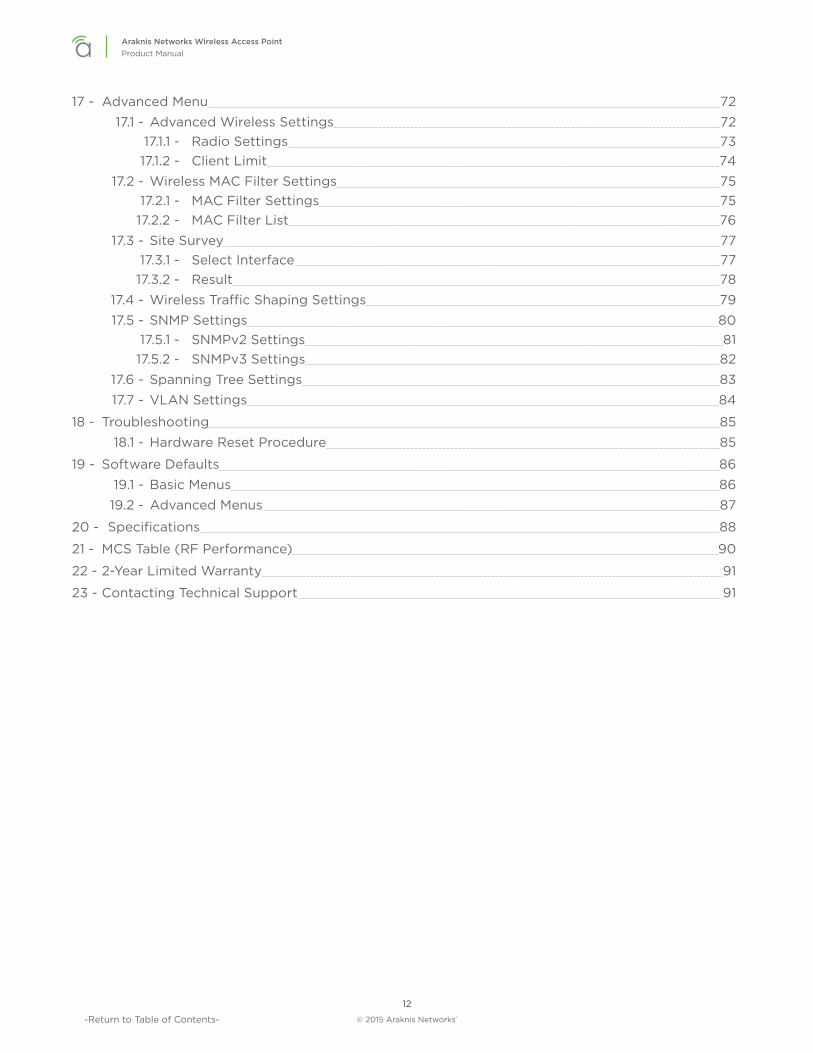
4 - Wiring RequirementsThe access point must be connected to the local network and powered using PoE (Power over Ethernet) or 12V DC power. Install the required cabling and equipment according to the guidelines in this section.
4.1 - Network Cable Requirements568B termination is recommended (Figure 4. EIA/TIA 568B Termination Pattern) Connect a Cat5e/6 straight-through cable between the access point and a local area network port on a switch or router.
Figure 4. EIA/TIA 568B Termination Pattern
(Gold pins facing up)
Pin 1 White/Orange Pin 5 White/Blue
Pin 2 Orange Pin 6 Green
Pin 3 White/Green Pin 7 White/Brown
Pin 4 Blue Pin 8 Brown
Note – Maximum cable length is 328 feet (100m). A repeater device is required for longer runs.
4.2 - PoE Requirements
Caution – Use an 802.3af/at compliant PoE injector, switch, or router to power the access point. Non-compliant devices can harm the access point and lead to unpredictable results.
4.3 - Power Requirements for Non-PoE ApplicationIf PoE is not being used, connect a suitable power supply (not included) from a nearby outlet to the DC input of the access point.
• AC Outlet – 100-240V AC, 50/60Hz (AN-100: 0.3A; AN-300: 0.6A)
• DC Input – 12V DC 1A (AN-100); 2A (AN-300).
4.4 - Wiring InstructionsPlan a mounting location and install the wiring before installing the access point.
Warning – Do not connect any equipment to the wiring until every connection has been terminated and testing is complete.
1. For PoE installations, install a network cable from the PoE device to the access point and terminate both ends to the same pattern. The DC power supply is not needed.
2. For non-PoE installations, locate an outlet for the power supply.
Pro Tip – If needed, extend a 2-conductor power wire from the power supply to the access point.
© 2015 Araknis Networks®
19
Araknis Networks Wireless Access PointProduct Manual Wiring Requirements
-Return to Table of Contents-
4.4.1 - Wiring Diagram
Figure 5. Network Wiring Diagram
Mobile Apps
ENABLED
Web Browser Access

© 2015 Araknis Networks®
20
Araknis Networks Wireless Access PointProduct Manual Mounting the Access Point
-Return to Table of Contents-
5 - Mounting the Access Point
5.1 - Table Top/ShelfThe access point comes with rubber feet installed for placement on flat surfaces. The mounting bracket is not required for this application.
5.2 - Junction Box MountingThe mounting bracket is compatible with most common junction box and plaster ring dimensions, including common ceiling box sizes:
• Single/Double Gang
• 4” Square Box
• 3” Octagonal Box
• 4” Octagonal Box
5.2.1 - Instructions1. Place the mounting bracket over the junction box and attach it loosely with 2 screws. (two 6-32
x 1” screws are included) Use the hole pattern on the bracket that best matches the box pattern. See Figure 5A.
2. Level or align the bracket with nearby objects for uniformity and tighten the screws enough to secure it. Avoid over-tightening and warping the bracket.
3. Connect the wiring to the access point and push any extra wiring back into the opening. See Figure 5B.
4. Snap the access point onto the bracket. See Figure 5C.
Figure 6. Junction Box Mounting
Figure 6A Figure 6B Figure 6C

© 2015 Araknis Networks®
21
Araknis Networks Wireless Access PointProduct Manual Mounting the Access Point
-Return to Table of Contents-
5.3 - Wall or Ceiling Drywall Mounting Instructions1. Place the bracket over the desired mounting location with the arrow on the bracket pointing up
for wall mounting. See Figure 6A.
2. Mark the “C” or “D” slots on the mounting surface, then remove the bracket and thread one of the included drywall anchors into the center of each mark using a Phillips screwdriver.
3. Level or align the bracket with nearby objects and fasten it to the anchors using the two included anchor screws. Tighten the screws enough to secure the bracket. Avoid over-tightening and warping the bracket.
4. Connect the wiring to the access point and push any extra wiring back into the opening. See Figure 6B.
5. Snap the access point onto the bracket. See Figure 6C.
Figure 7. Drywall Mounting
Figure 7A Figure 7B Figure 7C
5.4 - Ceiling Tile Mounting Instructions1. Place the bracket over the desired mounting location and
align it with nearby objects for uniformity.
2. Mark the “C” or “D” slots on the ceiling tile (and the center hole if needed for wiring).
3. Cut the opening with a keyhole saw. Use a drill to make clean holes for the mounting screws.
4. Place the ceiling backing plate and nuts on top of the tile as shown and fasten the mounting bracket to the tile using the included screws.
5. Connect the wiring to the access point and push any extra wiring back into the opening.
6. Snap the access point onto the bracket.
Figure 8. Ceiling Tile Mounting

© 2015 Araknis Networks®
22
Araknis Networks Wireless Access PointProduct Manual Power-On and Operation
-Return to Table of Contents-
6 - Power-On and OperationOnce the access point is powered, the status LED can be used to determine proper operation.
Pro Tip – Check the wireless network connection status in your PC to see if the default SSID “araknis_initial” is being broadcast. If the SSID is being broadcast, you may continue to the next section to begin configuring device access and software setup.
6.1 - Status LED OperationAfter installing the access point, connect the network and power cables and check the status LED. Once the LED remains illuminated (no more flashes), then the device is ready to be accessed for setup.
Figure 9. Status LED Location
Status LED
AN-300-AP-I-N
Status LED
AN-100-AP-I-N
Status LED
• Blue LED:
• Blinking: Device is not working correctly. Refer to the Troubleshooting section.
• Solid: Device is operating correctly.

© 2015 Araknis Networks®
23
Araknis Networks Wireless Access PointProduct Manual Introduction to Network Setup
-Return to Table of Contents-
7 - Introduction to Network SetupThe access point setup menu is used to make network configuration changes. This section explains how to access and use the menu.
Warning – All Araknis access points will transmit the same SSID, “araknis_initial” by default. If multiple access points are being installed in the same network, power on and complete network setup for one device at a time to avoid confusion about which access point you are connected to. Always change the SSID during initial setup.
8 - Accessing the Web InterfaceThere are several ways to access the web interface of the access point:
• EZ Access Method – Default method used for initial setup. Connect your computer to the access point using Wi-Fi.
• Configured System Name Access – Enter the device name instead of the IP address to access the web interface.
• DHCP/Static IP Address Method – Can be used any time. Connect your computer to the network wired or wirelessly and enter the IP address issued to the access point by the network, or the default IP address, (192.168.20.253).
• OvrC Method – OvrC gives you remote device management, real-time notifications, and intuitive customer management, right from your computer or mobile device. Setup is plug-and-play, with no port forwarding or DDNS address required. To add this device to your OvrC account:
1. Connect the WAP to the Internet
2. Log Into OvrC (www.ovrc.com)
3. Add the Device (MAC address and Service Tag numbers needed for authentication)

© 2015 Araknis Networks®
24
Araknis Networks Wireless Access PointProduct Manual Accessing the Web Interface
-Return to Table of Contents-
8.1 - EZ Access Method (Default)When the WAP is powered on for the first time, it transmits the default, unsecured SSID, “araknis_initial”. Connect and access the web interface without any cable connections or network card setting changes.
Note – Make sure the WAP is connected to a network with a functioning DHCP server. After the WAP is powered on, startup usually takes two to four minutes to complete. Wait for the Status LED to turn solid before beginning setup.
Figure 10. Default SSID
WAP set to DHCP by default
Network
PC set to DHCP
araknis_initial
On your wireless network-enabled computer:
1. Disconnect any network cables from your computer.
2. Make sure the wireless network card is set to obtain an IP address automatically (DHCP mode).
3. Connect your computer to the wireless network named “araknis_initial”.
4. Open a web browser and enter the configuration address for your device:• AN-100-AP-I-N enter: http://config.an100.wap/
• AN-300-AP-I-N enter: http://config.an300.wap/
5. Enter the default login credentials:• Username: araknis
• Password: araknis
Figure 11. EZ Setup Login Screen

© 2015 Araknis Networks®
25
Araknis Networks Wireless Access PointProduct Manual Accessing the Web Interface
-Return to Table of Contents-
8.2 - Configured System Name Access
Note – The “Araknis EZ Access” on page 63 must be enabled for this access method to work. The setting is enabled by default.
1. See section “11.1 - System Settings” on page 40 to set the system name.
2. Apply the settings. After configuration, the WAP web interface may be accessed using the system name.
3. Open a web browser and enter the configuration address for your WAP in this format (Example System Name = smith100):
• Enter into address bar: http://config.smith100.wap/
4. Enter the login credentials. (Default: araknis/araknis)
Figure 12. System Name Access

© 2015 Araknis Networks®
26
Araknis Networks Wireless Access PointProduct Manual Accessing the Web Interface
-Return to Table of Contents-
8.3 - DHCP/Static IP Address MethodConnect your computer to the network wired or wirelessly and enter the IP address issued to the access point by the network, or the default IP address, 192.168.20.253.
Note – If the WAP is not issued a DHCP IP address on the network, access the device using the default IP address.
8.3.1 - Finding the IP Address of the Access PointThe WAP is configured to DHCP by default so that the DHCP server can assign an IP address when the WAP is connected to the network (the DHCP server is usually the router). This address can be used for accessing the web interface.
1. Use one of these methods to find the IP address of the WAP:
• Check the client table on your router
• Use a network scanner (e.g. Fing) to sniff the network. The Araknis WAP manufacturer field will display Snap AV.
• See the highlighted field in the figure below for an example of an Araknis device being identified.
Figure 13. Fing IP Scanner Example
2. Once the IP address is found, enter it in your web browser and log in using the default credentials, or the new credentials, if they have been changed. (Default: araknis/araknis)
© 2015 Araknis Networks®
27
Araknis Networks Wireless Access PointProduct Manual Accessing the Web Interface
-Return to Table of Contents-
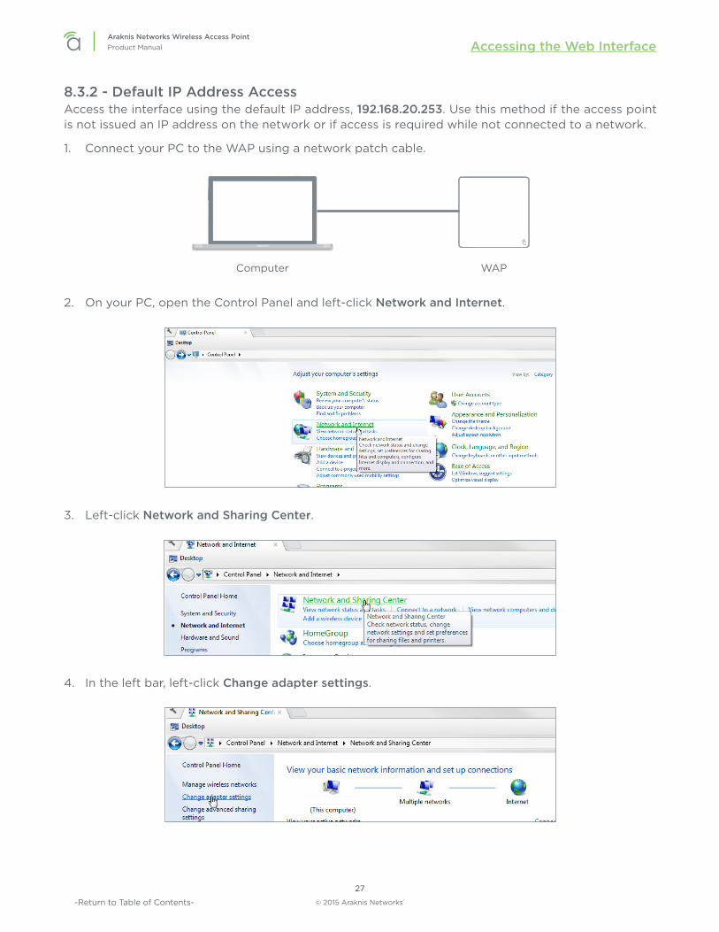
8.3.2 - Default IP Address AccessAccess the interface using the default IP address, 192.168.20.253. Use this method if the access point is not issued an IP address on the network or if access is required while not connected to a network.
1. Connect your PC to the WAP using a network patch cable.
Computer WAP
2. On your PC, open the Control Panel and left-click Network and Internet.
3. Left-click Network and Sharing Center.
4. In the left bar, left-click Change adapter settings.

© 2015 Araknis Networks®
28
Araknis Networks Wireless Access PointProduct Manual Accessing the Web Interface
-Return to Table of Contents-
5. Right-click the icon for the wired network connection and left-click Properties.
6. Left-click to highlight Internet Protocol Version 4 (TCP/IPv4), then left-click Properties.
7. In the General tab, left-click Use the following IP address: and enter the IP address and subnet mask.
• IP Address: 192.168.20.2
• Subnet Mask: 255.255.255.0
© 2015 Araknis Networks®
29
Araknis Networks Wireless Access PointProduct Manual Accessing the Web Interface
-Return to Table of Contents-
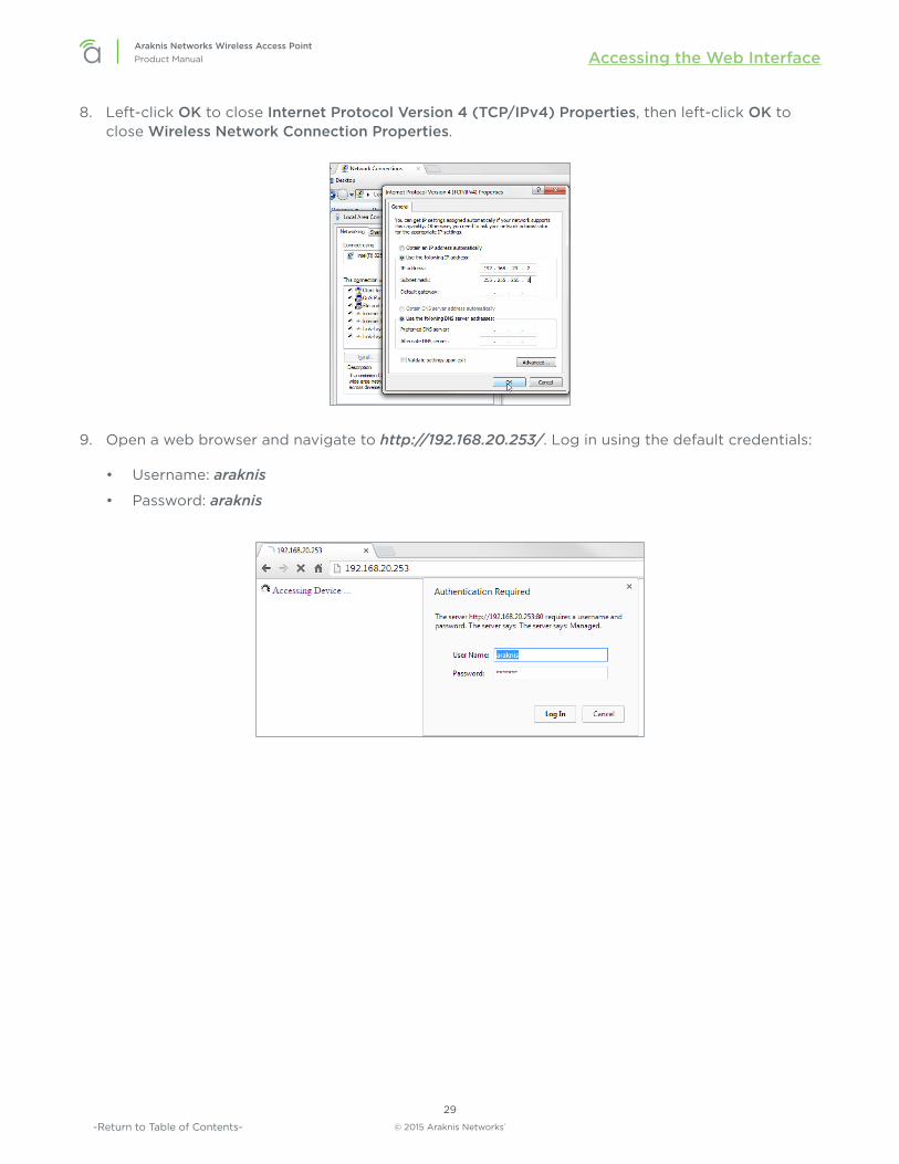
8. Left-click OK to close Internet Protocol Version 4 (TCP/IPv4) Properties, then left-click OK to close Wireless Network Connection Properties.
9. Open a web browser and navigate to http://192.168.20.253/. Log in using the default credentials:
• Username: araknis
• Password: araknis

© 2015 Araknis Networks®
30
Araknis Networks Wireless Access PointProduct Manual Web Interface Overview
-Return to Table of Contents-
9 - Web Interface OverviewFigure 14. Web Interface Layout
A B C
• A - Main Navigation MenuUse the submenus under the Status, Settings, Maintenance, and Advanced headings to configure and maintain the access point. Click Apply Changes to review and apply changes made in menus.
• B - Main WindowThe main window displays the currently selected submenu.
• C - Top BarThe top bar displays the current connection status to the OvrC server, the current internally-set
system time, and the current system uptime in DAYS:HOURS:MINUTES.

© 2015 Araknis Networks®
31
Araknis Networks Wireless Access PointProduct Manual Web Interface Overview
-Return to Table of Contents-
9.1 - Applying Changes in the Web Interface1. After making changes to settings on a menu page, left-click the Save button on the menu to hold
the new settings in the Apply Changes field.
2. After all desired changes have been made, left-click Apply Changes to review the new settings. Left-click Apply to make the changes or Revert to cancel the changes.
Figure 15. Applying Changes

© 2015 Araknis Networks®
32
Araknis Networks Wireless Access PointProduct Manual Status Menu
-Return to Table of Contents-
10 - Status Menu
10.1 - System StatusThe System Status screen provides a real-time summary of access point system information, and is the first screen that appears when you log into the access point web interface. Use the screen to verify settings and operation of your device.
Note – The figures displayed use AN-300-AP-I-N screenshots. AN-100 interfaces will indicate settings and information only for the 2.4GHz channel. The AN-300 will indicate settings and information for the 2.4GHz and 5GHz channels.
Figure 16. System Status Screen
Path – Status, System
10.1.1 - System Information
Figure 17. System Information Table
Path – Status, System, System Information
Parameters – • System Name – Name assigned to the system. Used for configured name access.
• Service Tag – Internal tracking number used to track every product sold by Araknis Networks.
• Firmware Version – Current version of firmware running on the access point.
• Management VLAN ID – VLAN that must be used to access the web interface.

© 2015 Araknis Networks®
33
Araknis Networks Wireless Access PointProduct Manual Status Menu
-Return to Table of Contents-
10.1.2 - Wireless InformationDisplays current information about the wireless radio channel(s) in use.
Figure 18. Wireless Information
Path – Status, System, Wireless Information
Parameters –
Note – The AN-100 will indicate settings and information for the 2.4GHz channel. The AN-300 will indicate settings and information for the 2.4GHz and 5GHz channels.
• MAC Address – Media Access Control (MAC) address. The 2.4GHz and 5GHz channels each have individual MAC addresses.
• Number of Networks – Number of active wireless networks (i.e. SSIDs) configured on the radio interface.
• Number of Connected Clients – Number of currently connected wireless clients on all configured networks using the radio interface.
• Operation Mode – Indicates that the device is set up as a Wi-Fi access point.
• TX – Amount of data, in bytes, transmitted on the respective radio interface since the last power cycle.
• RX – Amount of data, in bytes, received on the respective radio interface since the last power cycle.

© 2015 Araknis Networks®
34
Araknis Networks Wireless Access PointProduct Manual Status Menu
-Return to Table of Contents-
10.1.3 - LAN InformationThe LAN Information table displays current LAN connection parameters.
Figure 19. LAN Information
Path – Status, System, LAN Information
Parameters – • Speed – Indicates negotiated LAN speed between the access point and the wired network.
• Duplex – Indicates the negotiated duplex setting between the access point and the wired network.
• MAC address – The MAC address assigned to the access point network connection. This address may also be found on the acces point’s service tag.
• TX – Amount of data, in bytes, transmitted over the wired network connection.
• RX – Amount of data, in bytes, received from the wired network connection.
• IP Address – Access point IP address issued by the network router.
• Subnet Mask – Access point subnet mask.
• Default Gateway – Network router IP address.
• Primary DNS – Indicates the primary DNS for the AN-100/300.
• Secondary DNS – Indicates the secondary DNS for the AN-100/300.

© 2015 Araknis Networks®
35
Araknis Networks Wireless Access PointProduct Manual Status Menu
-Return to Table of Contents-
10.1.4 - System LogThe System Log table records all activity within the access point. The table refreshes to show the most recent activity when the System Status Page is opened.
Figure 20. System Log
Path – Status, System, System Log
Parameters – • System Log – The System Log records changes to access point configuration, connections,
security conditions, and more. The window will refresh with the most current activity when the System Status Page is opened.
10.1.4.1 - Using the System Log• Save Log – Click to view the log as a text file or save the log for future reference.
• Clear Log – Click to permanently delete to contents of the System Log.
© 2015 Araknis Networks®
36
Araknis Networks Wireless Access PointProduct Manual Status Menu
-Return to Table of Contents-
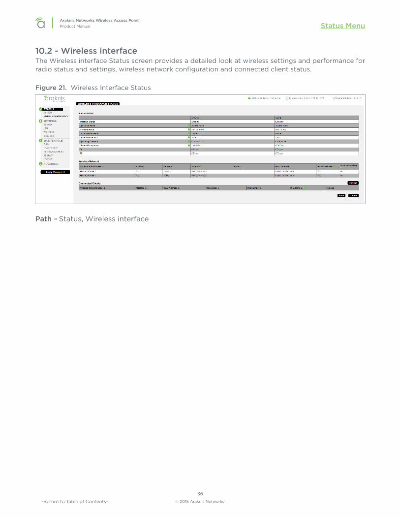
10.2 - Wireless interfaceThe Wireless interface Status screen provides a detailed look at wireless settings and performance for radio status and settings, wireless network configuration and connected client status.
Figure 21. Wireless Interface Status
Path – Status, Wireless interface

© 2015 Araknis Networks®
37
Araknis Networks Wireless Access PointProduct Manual Status Menu
-Return to Table of Contents-
10.2.1 - Radio StatusThe Radio Status table provides a detailed look at radio settings and performance.
Figure 22. Radio Status
Path – Status, Wireless interface, Radio Status
Parameters –
Note – The AN-100 will indicate settings and information for the 2.4GHz channel. The AN-300 will indicate settings and information for the 2.4GHz and 5GHz channels.
• Interface Status – Indicates whether the 2.4/5GHz wireless interface is enabled or disabled.
• Operation Mode – Access Point is the only mode currently supported.
• Wireless Mode – Indicates whether the wireless channel is in 802.11b/g/n or 802.11a/n mode.
• Channel Bandwidth – Set the bandwidth of the operating channel to 20MHz or 40MHz.
• Channel Selection – Select auto or manual channel selection mode of the wireless interface.
• Operating Channel – Indicates the selected channel for the wireless interface.
• Channel Frequency – Indicates the frequency of the selected channel.
• TX – Amount of data, in bytes, transmitted on each radio interface.
• RX – Amount of data, in bytes, received on each radio interface.

© 2015 Araknis Networks®
38
Araknis Networks Wireless Access PointProduct Manual Status Menu
-Return to Table of Contents-
10.2.2 - Wireless NetworkThe Wireless Network table provides a detailed look at wireless network settings.
Figure 23. Wireless Network Status
Path – Status, Wireless interface, Wireless Network
Parameters –
Note – The AN-100 will indicate settings and information for the 2.4GHz channel. The AN-300 will indicate settings and information for the 2.4GHz and 5GHz channels.
• Wireless Network(SSID) – Network names (SSIDs) being transmitted by the access point.
• Enabled – Indicates whether the wireless network is enabled or disabled.
• Interface – Indicates the operating frequency of the wireless network.
• Security – Indicates the security mode selected for the wireless network.
• VLAN ID – Indicates the VLAN ID for the wireless network.
• MAC address – MAC address of the wireless channel used by the network.
• Broadcast SSID – Indicates whether the SSID is visible to Wi-Fi devices and discovery tools.
• Channel Isolation – Indicates whether access point client devices connected to different SSIDs can communicate with each other.

© 2015 Araknis Networks®
39
Araknis Networks Wireless Access PointProduct Manual Status Menu
-Return to Table of Contents-
10.2.3 - Connected ClientsThe Connected Clients table provides a detailed look at connected wireless clients. All devices connected to any SSID on the access point will be displayed in the list.
Figure 24. Connected Client Status
Path – Status, Wireless interface, Connected Clients
Parameters – • Wireless Network (SSID) – Indicates the SSID being used by a connected wireless client.
• Interface – Indicates the channel frequency of a connected wireless client.
• MAC address – Indicates the MAC address of a connected wireless client.
• TX (KBytes) – Amount of data, in kilobytes, transmitted to a connected wireless client.
• RX (KBytes) – Amount of data, in kilobytes, received from a connected wireless client.
• RSSI (dBm) – Indicates the wireless signal strength between the access point and the connected client. The color of the table field indicates signal quality: green=strong, yellow=medium, and red=weak.
• Release – Click the Yes button to drop a client from the network.
Pro Tip – The closer RSSI (dBm) value is to 0, the stronger the signal is, and the closer to -100, the weaker the signal is.

© 2015 Araknis Networks®
40
Araknis Networks Wireless Access PointProduct Manual Settings Menu
-Return to Table of Contents-
11 - Settings Menu
11.1 - System SettingsThe System Settings screen allows configuration of basic system settings.
Figure 25. System Settings
Path – Settings, System

© 2015 Araknis Networks®
41
Araknis Networks Wireless Access PointProduct Manual Settings Menu
-Return to Table of Contents-
11.1.1 - System InformationThe System Information screen allows configuration of admin and access settings.
Figure 26. System Information
Path – Settings, System, System Information
Parameters – • System Name – Enter a meaningful name such as SmithHome or SmithBasement. Limited to 32
characters, including spaces. Can be used for system name access. See section “8.2 - Configured System Name Access” on page 25. Default: AN-100-AP-I-N: an100 ; AN-300-AP-I-N: an300
• Admin Username – Enter a new username for logging into the access point. Use letters, numbers, or punctuation. Limited to 32 characters, including spaces.Default: araknis
• Admin Current Password – Enter the current login password when changing the password.Default: araknis
• Admin New Password – Enter a new login password. Use letters, numbers, or punctuation. Limited to 32 characters, including spaces.
• Confirm Admin New Password – Confirm a new login password (enter same password as above).
• System LED – Turn the Status LED ON or OFF.Default: ON
• Management VLAN – The VLAN ID from where the WAP web interface must be accessed. If Management VLAN=10, your computer must also be on VLAN 10.Default: Untagged
Caution – Changing the management VLAN may cause a loss of access to the web interface. Move the computer to the new management VLAN or reset the WAP to regain connectivity (see section “12.3.1.4 - Hardware Factory Default” on page 68).
• Country – Select the country of the install location to comply with local standards.Default: United States
Configuration Instructions – 1. Click Settings, System.
2. Specify the system information settings.
3. Click Save.

© 2015 Araknis Networks®
42
Araknis Networks Wireless Access PointProduct Manual Settings Menu
-Return to Table of Contents-
11.1.2 - Wi-Fi SchedulerThe Wi-Fi Scheduler is used to configure when wireless networks are available for use. The scheduler is based on a 24-hour clock (00:00 = 12:00AM, the start of a given day).
Figure 27. Wi-Fi Scheduler
Path – Settings, System, Wi-Fi Scheduler
Parameters –
Note – The AN-100 will indicate settings and information for the 2.4GHz channel. The AN-300 will indicate settings and information for the 2.4GHz and 5GHz channels.
• Status – Enable or Disable the Wi-Fi Scheduler.Default: Disable
• Wireless Radio – Select 2.4GHz or 5GHz for the channel frequency to be scheduled.Default: 2.4GHz.
• SSID Selection – Select the SSID to be scheduled.
• Schedule Templates – Create different Wi-Fi schedules using templates as detailed below:
• Choose a Template – Select the template that matches the schedule requirements.
• Always Available – 00:00-24:00. The wireless network is always ON.
• Available 8-17 Daily – 08:00-17:00. The wireless network is ON at 8:00AM and OFF at 5:00PM.
• Available 8-17 Daily Except Weekends – 08:00-17:00. The wireless network is ON at 8:00AM and OFF at 5:00PM Monday-Friday and always OFF on Saturday and Sunday.
• Custom Schedule – Allows custom configuration of the wireless network ON/OFF schedule based upon user requirements.
• Schedule Table – Modify template schedules or make custom schedules. See the configuration instructions for setup.
• Day – Day of the week being configured.
• Availability – Select whether the device is Available for the set duration, or Unavailable for the specified day.
• Duration – Time setting from start to finish for availability in 24 hour format. 00:00=midnight; subtract 12 hours from 24 hour time for standard time 17:00-12:00=5:00pm;)

© 2015 Araknis Networks®
43
Araknis Networks Wireless Access PointProduct Manual Settings Menu
-Return to Table of Contents-
Configuration Instructions – Application example: The 2.4GHz SSID, “Market 2”, needs to be made available during the hours of 8AM to 6PM Monday through Friday, 10AM to 5PM on Saturdays, and unavailable the rest of the week.
Figure 28. Wi-Fi Scheduler Menu
1. Enable the Wi-Fi Scheduler feature.
2. Select the wireless frequency and SSID for scheduling. In our example, we will select 2.4GHz frequency, and the SSID, Market 2.
3. Select an option from the Schedule Templates dropdown to use. In our example, we will select Available 8-17 Daily, since this template is closest to the schedule needed.
4. Change the Schedule Table to work on the desired schedule. In our example, we will make the following changes:
• Sunday: Set to Unavailable so that no access is available the entire day.
• Monday-Friday: Set to Available and enter a duration of 08:00 - 18:00 (8AM-6PM)
• Saturday: Set to Available and enter a duration of 10:00 - 17:00 (10AM-5PM)
5. Click Save at the bottom of the System Information screen. Click Apply Changes to enable the new schedule. The figure below shows the configured and applied settings.
Figure 29. Wi-Fi Scheduler Setup Complete

© 2015 Araknis Networks®
44
Araknis Networks Wireless Access PointProduct Manual Settings Menu
-Return to Table of Contents-
11.1.3 - Date and Time SettingsThe Date and Time menu allows configuration of the ‘real world’ time setting and how it is kept correct for all access point functions.
Figure 30. Date and Time Settings
Path – Settings, System, Date and Time Settings
Parameters – • Manually Set Date and Time – Select to manually set date and time.
• Date – Enter the year, month and date (four digits for year; two digits for month, date)
• Time – Enter the hour and minutes for the correct current time. Use a mobile device or satellite clock for accuracy.
• Synchronize with PC – Click this button to automatically sync the access point to a connected computer.
• Automatically Get Date and Time – Select to automatically get date and time from various web resources.
• NTP Server – Select an NTP (Network Time Protocol) Server to set reference standard date and time. Default: time.nist.gov.
Configuration Instructions – 1. Click Settings, System.
2. Specify the date and time settings.
3. Click Save.

© 2015 Araknis Networks®
45
Araknis Networks Wireless Access PointProduct Manual Settings Menu
-Return to Table of Contents-
11.1.4 - Time ZoneThe menu allows configuration of time zone settings.
Figure 31. Time Zone
Path – Settings, System, Time Zone
Parameters – • Time Zone – Select the appropriate time zone from the drop-down.
• Enable Daylight Saving – Select to enable. DST start/end can change from year to year. Be sure to update this information.
• Start – Select the month, date, day and time Daylight Saving Time starts.
• End – Select the month, date, day and time Daylight Saving Time ends.
Configuration Instructions – 1. Click Settings, System.
2. Specify the time zone and DST settings.
3. Click Save.

© 2015 Araknis Networks®
46
Araknis Networks Wireless Access PointProduct Manual Settings Menu
-Return to Table of Contents-
11.2 - LAN SettingsThe LAN Settings screen allows configuration of the access point LAN connection to the network router. In default mode, the IP Settings screen will show the DHCP IP address and default subnet mask. A static IP address, subnet mask, default gateway and DNS settings can be configured by disabling DHCP. LAN speed can be configured in the Interface Settings screen.
Figure 32. LAN Settings
Path – Settings, LAN

© 2015 Araknis Networks®
47
Araknis Networks Wireless Access PointProduct Manual Settings Menu
-Return to Table of Contents-
11.2.1 - IP SettingsThe IP Settings menu is used to configure access point IP address settings. In default mode, the IP Settings screen will show the DHCP IP address and default subnet mask.
Figure 33. IP Settings
Note – By default, DHCP is enabled. DHCP is set to be disabled in this image to illustrate all the available options in the menu.
Path – Settings, LAN, IP Settings
Parameters –
Note – DHCP is the default setting. If a static IP address has been assigned, but DHCP is selected, the assigned IP address and subnet mask will be grayed out. To confirm the WAP IP address, see: System Status screen/LAN Information/IP address.
• IP Address – Uncheck DHCP Enable to enter a static IP address for the AN-100/300. A static IP address is recommended.
Warning – Be sure to use an IP address that is outside the DHCP server range to avoid duplicate addresses in the network.
• Subnet Mask – Enter the subnet mask for the AN-100/300.Default: 255.255.255.0
• Default Gateway – With DHCP disabled, enter the default gateway for the access point (network router IP address).
• Primary DNS – With DHCP disabled, enter the primary DNS for the AN-100/300. This will typically be the network router IP address.
• Secondary DNS – With DHCP disabled, enter the secondary DNS for the AN-100/300. This will typically be the network router IP address.
Note – Both primary and secondary DNS addresses are required if a static IP address is assigned.
• DHCP – Allows the access point to receive a DHCP IP address from the network router if DHCP is enabled. Un-check the box to configure a static IP address (recommended).Default: Enabled

© 2015 Araknis Networks®
48
Araknis Networks Wireless Access PointProduct Manual Settings Menu
-Return to Table of Contents-
Configuration Instructions – 1. Click Settings, LAN.
2. Specify the IP settings.
3. Click Save.

© 2015 Araknis Networks®
49
Araknis Networks Wireless Access PointProduct Manual Settings Menu
-Return to Table of Contents-
11.2.2 - Interface SettingsThe Interface Settings menu is used to configure LAN speed and duplex settings.
Figure 34. Interface Settings
Path – Settings, LAN, Interface Settings
Parameters – • Speed – Select LAN speed from Auto, 1Gbps (300 Series only), 100Mbps, 10Mbps, Disable (turns
the LAN Port OFF) Default: Auto
• Duplex – (10/100Mbps modes only) Select the duplex setting between the access point and the network router from Half or Full.Default: Full
Configuration Instructions – 1. Click Settings, LAN.
2. Specify the interface settings.
3. Click Save.

© 2015 Araknis Networks®
50
Araknis Networks Wireless Access PointProduct Manual Settings Menu
-Return to Table of Contents-
11.3 - Wireless SettingsThe Wireless Settings screen allows configuration of the access point’s wireless settings and connections including 2.4GHz and 5GHz Radio settings, setup and configuration of wireless networks (SSIDs) and all required wireless modes, channels, security settings and, guest network configuration.
Figure 35. Wireless Settings (AN-300-AP-I-N interface shown)
Path – Settings, Wireless

© 2015 Araknis Networks®
51
Araknis Networks Wireless Access PointProduct Manual Settings Menu
-Return to Table of Contents-
11.3.1 - Radio SettingsThe Radio Settings screen allows configuration of the access point’s radio settings including wireless modes, operating channels, channel bandwidth, and extension channel.
Figure 36. Radio Settings
Path – Settings, Wireless, Radio Settings
Parameters –
Note – The AN-100 will indicate settings and information for the 2.4GHz channel. The AN-300 will indicate settings and information for the 2.4GHz and 5GHz channels.
• Enable Interface – Enable or disable the radio interface.Default: Yes.
• Wireless Mode – Select the wireless mode for the radio. OPTIONS: 2.4GHz: 802.11b/g/n, 802.11b/g, 802.11b, 802.11g, 802.11n; 5GHz: 802.11a/n; 802.11a; 802.11n. Default: 2.4GHz - 802.11b/g/n; 5GHz - 802.11a/n.
• Operating Channel – Select the desired Wi-Fi channel. Use a different channel than other APs on the network. On the 2.4GHz radio there are only three non-overlapping channels: 1, 6 and 11. Select a channel as far away from close-numbered channels as possible.Default: Auto.
Pro Tip – In a multi-WAP environment, put adjacent WAPs on channels as far apart as possible. A spectrum analyzer tool (such as Metageek’s Chanalyzer Pro) is recommended for ultimate insight into the network setup.
• Channel Bandwidth – Select 20/40MHz for auto select; Select 20MHz for better performance as needed; select 40MHz for greater speed as needed. This option is only available in 802.11n modes. Default: 2.4GHz - 20MHz; 5GHz - 40MHz.
• Extension Channel – Only available when Wireless Mode is set to an 802.11n mode and channel Bandwidth is set to 20/40MHz or 40MHz. Extends the 20MHz channel to an Upper or Lower channel to achieve 40MHz bandwidth.Default: 2.4GHz - Upper Channel; 5GHz - Lower Channel.
Pro Tip – The access point features a Site Survey tool that shows all 2.4GHz/5GHz networks and settings. Use the tool to scan the wireless neighborhood and find the channel with the least amount of interference and the extension channel with less traffic from other wireless devices.
Enter xref in Extension channel

© 2015 Araknis Networks®
52
Araknis Networks Wireless Access PointProduct Manual Settings Menu
-Return to Table of Contents-
Configuration Instructions – 1. Click Settings, Wireless.
2. Specify the radio settings.
3. Click Save.

© 2015 Araknis Networks®
53
Araknis Networks Wireless Access PointProduct Manual Settings Menu
-Return to Table of Contents-
11.3.2 - Wireless NetworksThe Wireless Networks menu allows configuration of access point wireless networks (SSIDs), security settings, band steering and channel isolation.
Note – Be sure to change the SSID. The default settings are not secure.
Figure 37. Wireless Networks
Path – Settings, Wireless, Wireless Settings, Wireless Networks
Parameters –
Note – The AN-100 will indicate settings and information for the 2.4GHz channel. The AN-300 will indicate settings and information for the 2.4GHz and 5GHz channels.
• Enable – Select Yes to turn a wireless network ON. Default: Yes (Checked)
• Name (SSID) – Enter the network name for the network being configured.Default: araknis_initial; (Blank when adding a new network).
• Interface – Select 2.4GHz/5GHz or Both Channel Frequency.Default: Both, (2.4GHz when adding a network).
• Security Mode – Configure the security mode for each wireless network. Select a security mode from the drop-down to open the Wireless Security Setup Window (“Figure 38. Wireless Security – WPA-PSK and WPA2-PSK Modes” on page 54).
• Broadcast SSID – Select whether or not to publicly display the SSID to nearby Wi-Fi devices.Default: Yes
• Band Steering – (AN-300-AP-I-N only) Band steering uses both signal quality and throughput relative to the client device to determine whether the client should communicate on the 2.4- or 5GHz band. This optimizes signal strength to the device.Default: Disabled (Unchecked)
Note – Be sure to change the SSID. The default settings are not secure.
• Channel Isolation – Select to prevent communication between wireless clients on different SSIDs. Default: Not selected.
• Add – Click to add a wireless network.
• Delete – Click to delete a wireless network.

© 2015 Araknis Networks®
54
Araknis Networks Wireless Access PointProduct Manual Settings Menu
-Return to Table of Contents-
11.3.3 - Wireless Security MenuThe Wireless Security menu opens during the setup of an existing or new wireless network.
11.3.3.1 - WPA-PSK Mixed and WPA2-PSK Modes
Figure 38. Wireless Security – WPA-PSK and WPA2-PSK Modes
Path – Settings, Wireless, Wireless Networks, Security Mode
Parameters – • Name (SSID) – The name of the network being configured.
• Security Mode – Select a mode from the drop-down. Use the same mode as the network router and other APs on the network. Selecting a non-PSK mode will cause the menu options to change.
• Encryption – WPA2-PSK: AES; WPA2-PSK Mixed: Both (TKIP+AES).
• Passphrase – Enter the appropriate passphrase for the wireless network being configured. If using the ASCII format, the password must be 8-63 characters in length. If using HEX, the password must be 64 HEX characters in length.Default: Blank
• Group Key Update Interval – Enter a value to specify how often in seconds the Group key changes. RANGE: 30-3600 seconds.Default: 3600 (60 minutes)
• Save – Click to save changes to the Wireless Security Settings for this network. The window will close.
• Cancel – Click to cancel changes to the Wireless Security Settings for this network. The window will close.

© 2015 Araknis Networks®
55
Araknis Networks Wireless Access PointProduct Manual Settings Menu
-Return to Table of Contents-
11.3.3.2 - WPA and WPA2 Modes
Figure 39. Wireless Security – WPA-PSK and WPA2-PSK Modes
• Name (SSID) – The name of the network being configured.
• Security Mode – Select a mode from the drop-down. Use the same mode as the network router and other APs on the network. Selecting a PSK mode will cause the menu options to change.
• Encryption – Cannot be modified. WPA2: AES; WPA Mixed: Both (TKIP+AES).
• Group Key Update Interval – Enter how often the Group Key changes (from 30-3600 seconds).Default: 3600 (60 minutes)
• Radius Server – Enter the Radius Server IP address.Default: Blank
• Radius Port – Enter the Radius Server connection port number. Default: 1812 (This is a dedicated TCP/UDP port and typically should not be changed.)
• Radius Secret – Enter the Radius Server connection secret.Default: Blank
• Radius Accounting – Enable or disable Radius Accounting.Default: Disable
• Radius Accounting Server – Enter the Radius Accounting Server IP address.Default: Blank
• Radius Accounting Port – Enter the Radius Accounting Server connection port number.Default: 1813 (This is a dedicated TCP/UDP port and typically should not be changed.)
• Radius Accounting Secret – Enter the Radius Accounting Server connection secret.Default: Blank
• Interim Accounting Interval – Enter a value for how often accounting data will be sent, in seconds. RANGE: 60-600 seconds. Default: 600 (10 minutes)
• Save – Click to save changes. The window will close.
• Cancel – Click to cancel changes. The window will close.

© 2015 Araknis Networks®
56
Araknis Networks Wireless Access PointProduct Manual Settings Menu
-Return to Table of Contents-
11.3.4 - Guest NetworkUse the Guest Network menu to configure guest networks. These optional networks are useful for allowing access to temporary users and controlling what parts of the network they can access.
Figure 40. Guest Network
Path – Settings, Wireless, Guest Network
Parameters –
Note – The AN-100 will indicate settings and information for the 2.4GHz channel. The AN-300 will indicate settings and information for the 2.4GHz and 5GHz channels.
• Enable – Select to create a guest network. This will allow guests to log in to the wireless system without having to compromise network security by giving guests the password to the home network. There are separate 2.4GHz and 5GHz Guest Networks. If the guest is using an 802.11b/g device, (2.4GHz) they will only need the password to the 2.4GHz Network. If the guest is using an 802.11a/n device (5GHz) they will need the password to the 5GHz Network, and if the guest is using a device that can connect on both 2.4GHz and 5GHz, (iOS devices) they should have both. Default: Not Selected.
• Name (SSID) – Enter an SSID for the guest network. Default: Araknis-2.4_GuestNetwork; Araknis-5.0_GuestNetwork
• Edit – Click the Edit button to open the Guest Network Security Setup Window.
Note – Guest networks are limited to Open, WPA-PSK Mixed and WPA2-PSK encryption modes. See section “11.3.3.1 - WPA-PSK Mixed and WPA2-PSK Modes” on page 54 for encryption setup instructions.
• Security Mode – This indicates the Security Mode and Encryption selected in the Edit Mode, previous. Default: None
• Broadcast SSID – Selecting this option will allow the guest network SSID to appear in ‘Network Lists’ on wireless devices for user login. If not selected, the user will have to know the SSID and enter it manually to access the network. Default: Un-selected.
• Channel Isolation – Select to prevent communication between wireless clients on different SSIDs of the guest network. Default: Selected.

© 2015 Araknis Networks®
57
Araknis Networks Wireless Access PointProduct Manual Settings Menu
-Return to Table of Contents-
• Manual IP Settings – Use the access point’s defaults or manually enter IP address settings.
• Gateway IP Address – Enter the access point’s Guest Network Gateway IP address. Default: 192.168.200.1
• Subnet Mask – Enter the subnet mask for the access point’s Guest Network Gateway.Default: 255.255.255.0
• Automatic DHCP Server Settings
• Starting IP Address – Enter the lowest address available for the Guest Network.Default: 192.168.200.100
• Ending IP Address – Enter the highest address available for the Guest Network.Default: 192.168.200.200
• WINS Server IP – Enter the IP address for the WINS Server for the Guest Network.Default: 0.0.0.0

© 2015 Araknis Networks®
58
Araknis Networks Wireless Access PointProduct Manual Settings Menu
-Return to Table of Contents-
11.4 - Security SettingsThe Security Settings screen allows configuration of who can log into the access point interface and what level of privileges they have, how the device can be accessed, email notification of system status and warnings, and device discovery.
Figure 41. Security Settings
Path – Settings, Security

© 2015 Araknis Networks®
59
Araknis Networks Wireless Access PointProduct Manual Settings Menu
-Return to Table of Contents-
11.4.1 - User AccountsThe User Accounts menu allows configuration of who can log into the access point and what level of privileges they have.
Figure 42. User Accounts
Path – Settings, Security, User Accounts
Parameters – • Select – Select to allow editing of the selected table entry.
Default: Not selected
• Username – Click the Edit button to access the settings on a selected User Account. Enter a new username for logging into the access point. Use letters, numbers, or punctuation. Limited to 32 characters, including spaces.Default: araknis (Blank when adding a new account)
• Privilege Level – Indicates the level of device management for the logged in user. OPTIONS: admin, Status, Status+Settings.Default: admin Status+Settings when adding a new account)
• Password – Enter a new login password. Use letters, numbers, or punctuation. Limited to 32 characters, including spaces.Default: araknis (Blank when adding a new account)
• Confirm Password – Confirm a new login password (enter same password as above).Default: araknis (Blank when adding a new account)
• Delete – Click the icon to delete a specific user account.
• Add – Click to add a new user account.
• Edit – Click the Select arrow in the left column of a user account and click Edit to modify the account.
Configuration Instructions – 1. Click Settings, Security.
2. Specify the user account settings.
3. Click Save.

© 2015 Araknis Networks®
60
Araknis Networks Wireless Access PointProduct Manual Settings Menu
-Return to Table of Contents-
11.4.2 - Access ControlThe Access Control menu allows configuration of how the access point can be accessed.
Figure 43. Access Control
Path – Settings, Security, Access Control
Parameters – • HTTP Port – Enter device web server port to connect.
Default: 80
Pro Tip – Assign a unique port number to enable remote access to the access point web interface via port forwarding on the network router.
• Web Access – Select Enable or Disable to enable or disable the ability to modify the device via Web Browser. Default: Enable
Caution – Disabling web access will cause a loss of connection to the web interface. If this occurs, regain connectivity by restoring the hardware to factory default settings. (Press Reset button for 10 seconds.)
• Telnet – Select Enable or Disable to enable or disable the ability to modify the device via a command line interface (CLI) through a telnet session. Default: Enable
• SSH – Select Enable or Disable to enable or disable the ability to modify the device via a command line interface (CLI) with a secure channel. Default: Disable
Configuration Instructions – 1. Click Settings, Security.
2. Specify the access control settings.
3. Click Save.

© 2015 Araknis Networks®
61
Araknis Networks Wireless Access PointProduct Manual Settings Menu
-Return to Table of Contents-
11.4.3 - Email AlertThe Email Alert menu allows configuration of the email notification system for status and warnings.
Figure 44. Email Alert Setup Example
Path – Settings, Security, Email Alerts
Parameters – • Status – Select Enable to send email notifications in the event of certain abnormal conditions.
Default: Not selected
• From – Enter the email address of the sender. Default: Blank
• To – Enter the email address of the recipient. Default: Blank
• Subject – Information regarding the nature of the system condition. Default: [Email-Alert][araknis][88:DC:96:1D:33:6B][Configuration Changed]
• Email Account –
• Username – Enter the username for the email account (Outlook, Gmail, etc.) sending the alert. Default: Blank
• Password – Enter the password for the email account (Outlook, Gmail, etc.) sending the alert.Default: Blank
• SMTP Server – Enter the SMTP Server and Port Number of the email client sending emails.Default: SMTP Server Blank; Port: 25
• Security Mode – Select a security mode for sending Email Alerts. None, SSL/TLS, STARTTLS Default: None
• Send Test Email – Click the button to send a test email to confirm Email Alert settings.
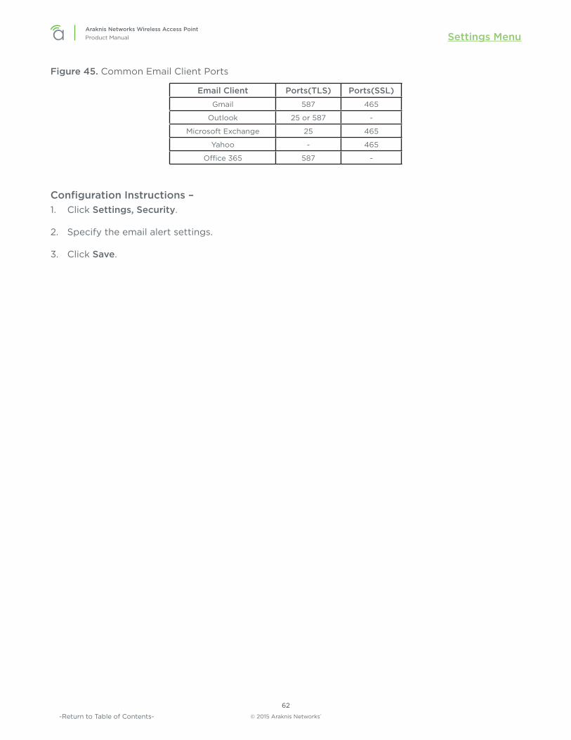
© 2015 Araknis Networks®
62
Araknis Networks Wireless Access PointProduct Manual Settings Menu
-Return to Table of Contents-
Figure 45. Common Email Client Ports
Email Client Ports(TLS) Ports(SSL)Gmail 587 465
Outlook 25 or 587 -
Microsoft Exchange 25 465
Yahoo - 465
Office 365 587 -
Configuration Instructions – 1. Click Settings, Security.
2. Specify the email alert settings.
3. Click Save.

© 2015 Araknis Networks®
63
Araknis Networks Wireless Access PointProduct Manual Settings Menu
-Return to Table of Contents-
11.4.4 - Device DiscoveryThe Device Discovery menu allows configuration of how or if the access point can search for and connect to network devices via Bonjour and UPnP.
Figure 46. Device Discovery
Path – Settings, Security, Device Discovery
Parameters – • Bonjour – Enable to allow the access point to search for and connect to network devices running
Apple iOS and OS X. Bonjour can also be run on devices running a Microsoft OS. Default: Disable
• UPnP – Enable to allow the access point to search for and connect to network devices via UPnP Protocol (Universal Plug and Play). Default: Disable
• Araknis EZ Access – Use a URL to access the web interface (see section “8.2 - Configured System Name Access” on page 25).Default: Enable
Caution – If VLANs are enabled, this setting will automatically become disabled. In order for VLANs to work correctly, it must remain disabled and will require you to use the local IP address of the WAP in order to gain access to the GUI.
Configuration Instructions – 1. Click Settings, Security.
2. Specify the device discovery settings.
3. Click Save.

© 2015 Araknis Networks®
64
Araknis Networks Wireless Access PointProduct Manual Maintenance
-Return to Table of Contents-
12 - Maintenance
12.1 - Ping TestThe Ping Test screen can be used to determine if a particular IP address can be reached across an IP network.
Figure 47. Ping Test
Path – Maintenance, Ping
Parameters – • Target IP / Domain Name – Enter the IP address of a device or web page to determine if it can be
reached.
• Ping Packet Size – Enter the packet size of each ping. Maximum size: 65535.Default: 64 Bytes
• Number of Pings – Enter the number of ping attempts. Default: 4
• Start – Click the Start button to send the Ping. Ping Test results will be displayed in the text frame. Ideal results: Same number of packets transmitted/received, 0% packet loss.
Configuration Instructions – 1. Click Maintenance, Ping.
2. Specify the ping test settings.
3. Click Start.

© 2015 Araknis Networks®
65
Araknis Networks Wireless Access PointProduct Manual Maintenance
-Return to Table of Contents-
12.2 - Traceroute TestThe Traceroute Test screen can be used to display the route and delays for data packets to/from a destination on an IP network.
Figure 48. Traceroute Test
Path – Maintenance, Traceroute
Parameters – • Target IP / Domain Name – Enter the IP address of a device or web page to show the path of
communication to that device or website.
• Start – Click the Start button to start Traceroute. Traceroute Test results will be displayed in the text frame.
• Stop – Click the Stop button to stop Traceroute.
Configuration Instructions – 1. Click Maintenance, Traceroute.
2. Specify the traceroute test settings.
3. Click Start.
4. Click Stop to end the test.

© 2015 Araknis Networks®
66
Araknis Networks Wireless Access PointProduct Manual Maintenance
-Return to Table of Contents-
12.3 - File ManagementUse the File Management screen to back up or restore settings and apply firmware updates.
Figure 49. File Management
Path – Maintenance, File Management

© 2015 Araknis Networks®
67
Araknis Networks Wireless Access PointProduct Manual Maintenance
-Return to Table of Contents-
12.3.1 - Configuration FileUse the Configuration File menu to back up or restore settings to the access point.
Figure 50. Configuration File
Path – Maintenance, File Management, Configuration File
12.3.1.1 - Backup Current ConfigurationSave the access point’s current configuration settings to a “.tar” format compressed archive on your computer.
1. Click the To PC button and select a location to save the file.
2. Name the file and save it to your computer.
12.3.1.2 - Upload New Configuration FileRestore previously saved configuration settings to the access point to restore settings.
1. Click the Choose File button and select a configuration file (“.tar” file type) from the Open window.
2. The file name will appear to the right of the Choose File button as shown in Figure 51. Uploading a New Configuration File, below.
3. Click the From PC button to upload the configuration file. Wait while the Rebooting screen opens and loads the selected configuration. When the upload is finished, the Authentication Required (Log In) window will open.
4. Log in and confirm Configuration settings.
Figure 51. Uploading a New Configuration File

© 2015 Araknis Networks®
68
Araknis Networks Wireless Access PointProduct Manual Maintenance
-Return to Table of Contents-
12.3.1.3 - Restore Factory DefaultsUse the File Management screen to restore default settings.
Note – When restoring factory defaults, the SSID, IP address, subnet mask, and gateway IP address will also be reset. Reconnect to the access point using the instructions beginning in section “8.1 - EZ Access Method (Default)” on page 24.
Figure 52. Restore Factory Defaults
Path – Maintenance, File Management, Configuration File, Restore Factory Defaults
Note – All current settings will be permanently lost if not backed up. See Backup Current Configuration, above, to backup current settings prior to executing Restore to Factory Defaults.
Configuration Instructions – 1. Click the Yes button to restore the access point to factory default settings. The red ALERT
message will appear.
2. Click Confirm to restore factory defaults. Wait while the rebooting screen is open and loading the selected configuration. When the configuration upload is finished, the login window will appear.
3. Enter the username and password. (araknis; araknis)
4. Confirm the new configuration settings.
12.3.1.4 - Hardware Factory DefaultIf restoring factory defaults does not restore proper functionality to the AN-100/300, a hardware reset may be performed to reload the original base configuration file (saved in the access point’s memory).
Configuration Instructions – 1. Using a paper clip or other small, blunt tool press the reset button located on the top of the
access point for 30 seconds.
2. After two to four minutes, the WAP will reboot. Restart the setup process or upload a previously saved configuration.

© 2015 Araknis Networks®
69
Araknis Networks Wireless Access PointProduct Manual Maintenance
-Return to Table of Contents-
12.3.1.5 - FirmwareUse the Firmware menu to upload new firmware to the AN-100/300.
Figure 53. Firmware
Path – Maintenance, File Management, Firmware
Parameters – • Current Firmware Version – Indicates the current running firmware version.
• Date Activated – Date the current firmware was uploaded and activated.
Configuration Instructions – 1. Click the Browse button to navigate to where the firmware file is saved.
2. Select the file and then press Enter/Return on the computer keyboard or click Open on the Upload menu. (The firmware file name should appear next to the Upload New Firmware File Browse button.)
3. Click Upload. The Upload Firmware Information screen will open.
4. Click Upgrade. Wait while the new firmware loads. When the configuration upload is finished, the login screen will appear.
5. Enter the username and password.
6. Confirm the firmware version.

© 2015 Araknis Networks®
70
Araknis Networks Wireless Access PointProduct Manual Maintenance
-Return to Table of Contents-
12.4 - RestartReboot the access point.
Figure 54. Restart
Path – Maintenance, Restart
Configuration Instructions – 1. Click the Reboot the Device button. The message, “This will reboot the device and may take a few
seconds...” will appear.
2. Click OK to reboot (or Cancel to return to the Restart Screen).
3. Wait while the access point reboots. When the device has rebooted, the login screen will appear.
4. Enter the username and password.
5. Confirm the firmware and configuration.

© 2015 Araknis Networks®
71
Araknis Networks Wireless Access PointProduct Manual Maintenance
-Return to Table of Contents-
12.5 - LogoutLogout can be used to change the user currently logged into setup. After working in the setup screens, a logged in user can simply close the browser tab or click Logout. Closing the browser tab will close the setup screen completely, Logout will end the session for the logged in user and open the Authentication Required (Log In) window.
Figure 55. Logout Alert
Path – Maintenance, Logout
Configuration Instructions – 1. From any screen, click Logout in the system menu. The Logout ALERT will appear on screen.
2. Click Cancel to return to the setup screen; click Confirm to log the current user out.

© 2015 Araknis Networks®
72
Araknis Networks Wireless Access PointProduct Manual Advanced Menu
-Return to Table of Contents-
13 - Advanced Menu
Note – Advanced menu settings should not require any changes for most applications.
13.1 - Advanced Wireless SettingsThe Advanced Wireless Settings screen allows configuration of radio settings for unit of measure, data rate, power and RTS/CTS Threshold as well as a client limit by band, (2.4GHz/5GHz).
Figure 56. Advanced Wireless Settings
Path – Advanced, Wireless Settings

© 2015 Araknis Networks®
73
Araknis Networks Wireless Access PointProduct Manual Advanced Menu
-Return to Table of Contents-
13.1.1 - Radio SettingsThe Advanced Wireless Settings menu allows configuration of radio settings for unit of measure, data rate, power and RTS/CTS Threshold.
Figure 57. Radio Settings
Path – Advanced, Wireless Settings, Radio Settings
Parameters – • Transmit Power Unit – Select the preferred unit of measure. OPTIONS: dBm, mW.
Default: dBm.
• Data Rate – Select a setting from the drop-down to set the available transmit data rate permitted for connected clients. A lower data rate reduces throughput, but increases the transmission range. OPTIONS: See drop-down list. Default: Auto.
• Transmit Power – Select a setting from the drop-down to set the radio power. A higher gain will improve performance but can also cause interference with other access points in close range on the same channel. Also, a higher coverage range corresponds with lower throughput (i.e. to achieve the highest transmit power, the connection must run at the lowest data rate). Set this value as low as possible (for adequate coverage) to get the maximum wireless speed/data throughput. OPTIONS: See drop-down list. Default: Full 100% -29dBm.
• RTS/CTS Threshold (Range: 1-2346) – Enter a value for the threshold package size for RTS/CTS (request to send/clear to send). A lower number increases the frequency that the packets are sent and consumes more bandwidth. RANGE: 1-2346. Default: 2346
Configuration Instructions – 1. Click Advanced, Wireless Settings.
2. Specify the radio settings.
3. Click Save.

© 2015 Araknis Networks®
74
Araknis Networks Wireless Access PointProduct Manual Advanced Menu
-Return to Table of Contents-
13.1.2 - Client LimitThe Advanced Wireless Settings screen allows configuration of client limit by band, (2.4GHz/5GHz).
Figure 58. Client Limit Settings
Path – Advanced, Wireless Settings, Client Limit
Parameters –
Note – The AN-100 will indicate settings and information for the 2.4GHz channel. The AN-300 will indicate settings and information for the 2.4GHz and 5GHz channels.
• Enable – Select to enable Client Limit, by channel. Default: Not Selected.
• Max Client No. – Set the maximum number of clients that can be connected to a channel at a given time. (For AN-300, the maximum number of clients is for each radio interface.) RANGE: 1-127. Default: 127.
Pro Tip – It is recommended to design the wireless network so that each access point can handle 30 clients at a given time.
Configuration Instructions – 1. Click Advanced, Wireless Settings.
2. Specify the client limit settings.
3. Click Save.

© 2015 Araknis Networks®
75
Araknis Networks Wireless Access PointProduct Manual Advanced Menu
-Return to Table of Contents-
13.2 - Wireless MAC Filter SettingsThe Wireless MAC Filter determines if wireless clients (computers, tablets, smartphones) can access the wireless network as defined by client MAC address. Authorized clients can be configured and viewed in the MAC Filter List.
Figure 59. Wireless MAC Filter Settings
Path – Advanced, MAC Filter
13.2.1 - MAC Filter SettingsThe MAC Filter Settings screen enables/disables Wireless MAC Filtering.
Figure 60. MAC Filter Settings
Path – Advanced, MAC Filter, MAC Filter Settings
Parameters – • Enable MAC Filter – Select Yes to enable MAC Filtering.
Default: Not Selected.
• Filter Mode – Select Allow to permit wireless clients access to the wireless network as defined by wireless client MAC address. Select Deny to prevent wireless clients from accessing the wireless network as defined by wireless client MAC address. OPTIONS: Allow, Deny. Default: Allow.
Configuration Instructions – 1. Click Advanced, MAC Filter.
2. Specify the wireless MAC filter settings.
3. Click Save.

© 2015 Araknis Networks®
76
Araknis Networks Wireless Access PointProduct Manual Advanced Menu
-Return to Table of Contents-
13.2.2 - MAC Filter ListThe Wireless MAC Filter List screen can be used to add/delete wireless clients to be filtered by MAC address.
Figure 61. MAC Filter List
Path – Advanced, MAC Filter, MAC Filter List
Parameters – • No. – The client number for a device being filtered by MAC address.
Default: Not available if MAC Filtering is disabled; client number is in the list if MAC Filtering is enabled.
• MAC address – The MAC address of a client being filtered by MAC address, if MAC address filtering is enabled. Default: Blank.
• Add – Click to add a new client to be filtered by MAC address.
• Delete – Click to delete an existing client.
Configuration Instructions – 1. Click Advanced, MAC Filter.
2. Specify the MAC filter settings.
3. Click Save.

© 2015 Araknis Networks®
77
Araknis Networks Wireless Access PointProduct Manual Advanced Menu
-Return to Table of Contents-
13.3 - Site SurveyThe access point provides a convenient on-board Wi-Fi detection tool commonly known as a Wi-Fi sniffer that can be used to detect the presence of other 2.4GHz and 5GHz wireless networks. Parameters such as their modes, channels, security settings, signal strengths, encryptions, and types can be identified. Having this information can be useful during setup to avoid conflicts with other networks in the wireless neighborhood.
Figure 62. Site Survey Settings
Path – Advanced, Site Survey
13.3.1 - Select InterfaceThe Site Survey Select Interface screen can be used to select the frequency (2.4GHz/5GHz) to be scanned.
Figure 63. Site Survey Settings - Select Interface
Path – Advanced, Site Survey, Select Interface
Parameters –
Note – The AN-100 will indicate settings and information for the 2.4GHz channel. The AN-300 will indicate settings and information for the 2.4GHz and 5GHz channels.
• Select Interface – Select whether to scan for 2.4GHz or 5GHz networks.
• Scan Nearby Networks – Click the Scan button to begin a scan.
Configuration Instructions – 1. Click Advanced, Site Survey.
2. Specify the site survey settings.
3. Click Scan.

© 2015 Araknis Networks®
78
Araknis Networks Wireless Access PointProduct Manual Advanced Menu
-Return to Table of Contents-
13.3.2 - ResultThe Site Survey Result shows detected 2.4GHz/5GHz wireless networks, their modes, channels, security settings, signal strengths, encryptions, and type based upon the frequency selected for scanning.
Figure 64. Site Survey Settings - shown with scan results
Path – Advanced, Site Survey, Result
Parameters – • BSSID – Basic Service Set Identification. Indicates the MAC address of a detected 2.4GHz or 5GHz
neighboring access point.
• SSID – Service Set Identifier. Indicates the network name of a wireless network that a specific device is connected to.
• Mode – Indicates how a device is being used i.e. AP, bridge, etc.
• Channel – Indicates the channel a specific device is transmitting on.
• Signal – RSSI or Received Signal Strength Indicator. Indicates the signal strength of a detected network as received by the AN-100/300.
• Encryption – Indicates the security mode encryption of a detected device.
• Type – Indicates the wireless mode of the detected device.

© 2015 Araknis Networks®
79
Araknis Networks Wireless Access PointProduct Manual Advanced Menu
-Return to Table of Contents-
13.4 - Wireless Traffic Shaping SettingsTraffic shaping is used to regulate packet flow to control wireless network saturation and improve (reduce) latency.
Figure 65. Wireless Traffic Shaping Settings
Path – Advanced, Traffic Shaping
Parameters –
Note – The AN-100 will indicate settings and information for the 2.4GHz channel. The AN-300 will indicate settings and information for the 2.4GHz and 5GHz channels.
• Enable – Select to enable Traffic Shaping on the 2.4GHz and/or 5GHz band.
• SSID – Indicates the network to which Traffic Shaping will be applied.
• Interface – Indicates 2.4GHz or 5GHz band.
• Download Limit – Enter a value to regulate download speed. RANGE: 1-999Mbps. Default: 100Mbps.
• Upload Limit – Enter a value to regulate upload speed. RANGE: 1-999Mbps. Default: 100Mbps.
Configuration Instructions – 1. Click Advanced, Traffic Shaping.
2. Specify the wireless traffic shaping settings.
3. Click Save.

© 2015 Araknis Networks®
80
Araknis Networks Wireless Access PointProduct Manual Advanced Menu
-Return to Table of Contents-
13.5 - SNMP SettingsSimple Network Management Protocol (SNMP) is an IP network protocol that can be used to monitor network devices, audit network usage, detect network faults or inappropriate access, and, in some cases, configure remote devices.
Figure 66. SNMP Settings
Path – Advanced, SNMP
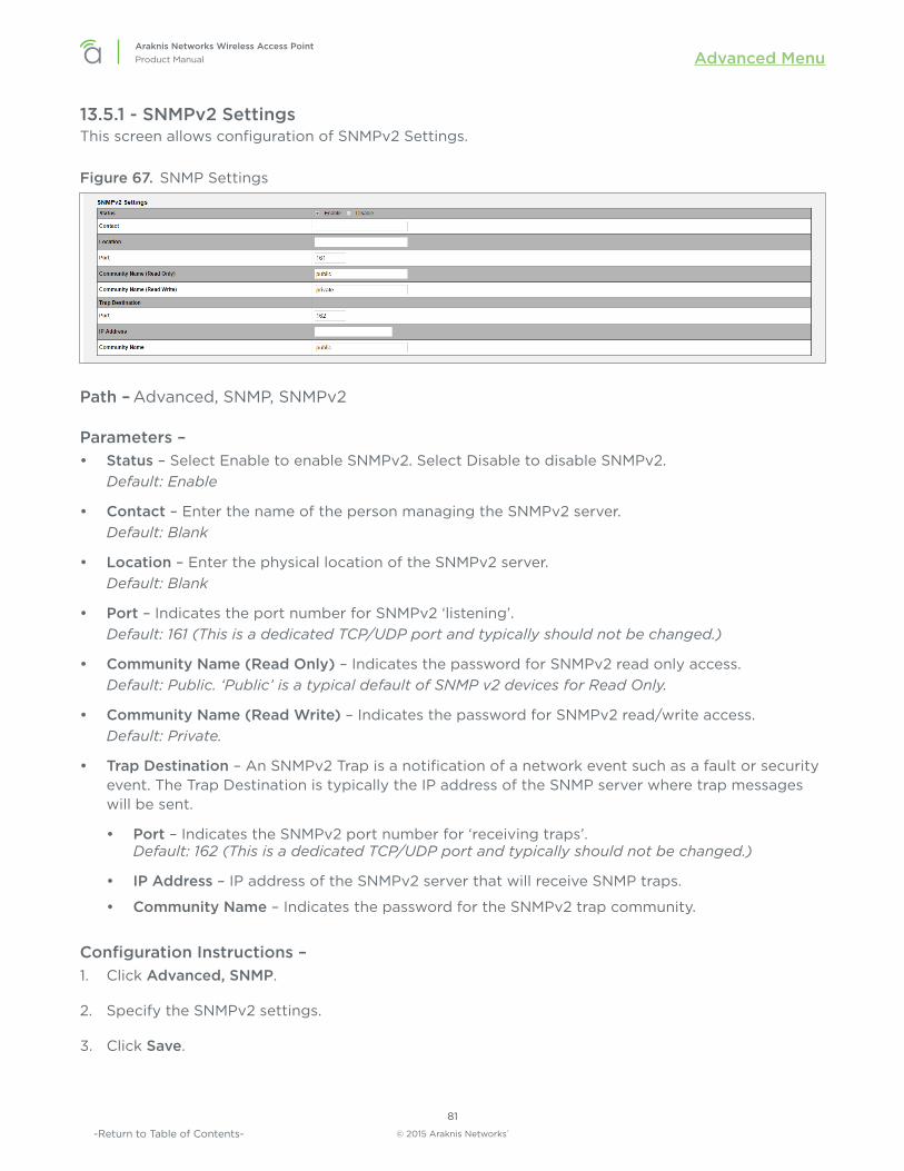
© 2015 Araknis Networks®
81
Araknis Networks Wireless Access PointProduct Manual Advanced Menu
-Return to Table of Contents-
13.5.1 - SNMPv2 SettingsThis screen allows configuration of SNMPv2 Settings.
Figure 67. SNMP Settings
Path – Advanced, SNMP, SNMPv2
Parameters – • Status – Select Enable to enable SNMPv2. Select Disable to disable SNMPv2.
Default: Enable
• Contact – Enter the name of the person managing the SNMPv2 server. Default: Blank
• Location – Enter the physical location of the SNMPv2 server. Default: Blank
• Port – Indicates the port number for SNMPv2 ‘listening’.Default: 161 (This is a dedicated TCP/UDP port and typically should not be changed.)
• Community Name (Read Only) – Indicates the password for SNMPv2 read only access. Default: Public. ‘Public’ is a typical default of SNMP v2 devices for Read Only.
• Community Name (Read Write) – Indicates the password for SNMPv2 read/write access. Default: Private.
• Trap Destination – An SNMPv2 Trap is a notification of a network event such as a fault or security event. The Trap Destination is typically the IP address of the SNMP server where trap messages will be sent.
• Port – Indicates the SNMPv2 port number for ‘receiving traps’.Default: 162 (This is a dedicated TCP/UDP port and typically should not be changed.)
• IP Address – IP address of the SNMPv2 server that will receive SNMP traps.
• Community Name – Indicates the password for the SNMPv2 trap community.
Configuration Instructions – 1. Click Advanced, SNMP.
2. Specify the SNMPv2 settings.
3. Click Save.

© 2015 Araknis Networks®
82
Araknis Networks Wireless Access PointProduct Manual Advanced Menu
-Return to Table of Contents-
13.5.2 - SNMPv3 SettingsThis screen allows configuration of SNMPv3 Settings.
Figure 68. SNMP Settings
Path – Advanced, SNMP, SNMPv3
Parameters – • Status – Select Enable to enable SNMPv3. Select Disable to disable SNMPv3.
Default: Enable
• Username – Enter a username for SNMPv3 implementation. RANGE: 1-31 Characters. Default: admin.
• Authorized Protocol – Select the desired protocol from the drop-down. OPTIONS: MD5, SHA, None. Default: MD5
• Authorized Key – Enter an authentication key. This key acts as an electronic signature to authenticate an SNMPv3 message. RANGE: 8-32 Characters. Default: 12345678
• Privacy Protocol – Select the desired protocol from the drop-down. OPTIONS: DES, None. Default: DES
• Privacy Key – Enter a Privacy Key. This acts as an encryption for the data within a SNMPv3 message. RANGE: 1-8 Characters. Default: 12345678
• Engine ID – Enter an Engine ID. The Engine ID identifies where a SNMPv3 message is coming from. Default: Blank
Configuration Instructions – 1. Click Advanced, SNMP.
2. Specify the SNMPv3 settings.
3. Click Save.

© 2015 Araknis Networks®
83
Araknis Networks Wireless Access PointProduct Manual Advanced Menu
-Return to Table of Contents-
13.6 - Spanning Tree SettingsSpanning Tree Protocol (STP) is an IP network protocol that prevents undesirable loops caused by multiple active paths between network devices when multiple switches or bridges are used on a network.
Figure 69. Spanning Tree Settings
Path – Advanced, SNMP, Spanning Tree
Parameters – • Status – Enable or Disable STP.
Default: Disable
• Hello Time – Enter a value for Hello Time. This setting will determine how often in seconds the access point will send the Hello Message to network switches and bridges to assess network topology. RANGE: 1-10 seconds. Default: 2 seconds
• Max Age – Enter a duration for Max Age. This setting will determine how long the access point will wait for a Hello Message from another switch or bridge. If no message is received within the set duration, the device will be considered off-line and a new STP route will be configured. RANGE: 6-40 seconds. Default: 20 seconds.
• Forward Delay – Enter a value for Forward Delay. This setting will determine the length of time the access point will take to ‘listen’ to the network and either retain current topology or generate a new topology based upon network switch and bridge status. RANGE: 4-30 seconds. Default: 4 seconds.
• Priority – Enter a value for Priority from 0-65535. This setting will help determine which bridge is the root bridge, or essentially, the switch that controls the main road that network traffic is going to be routed around to avoid loops. In this game, the lowest score wins. The score is a total of MAC address, the Priority number and a bunch of tie-breaker values that determine the root bridge. Setting a lower Priority will help generate a lower score for a given switch.Default: 32768.
Configuration Instructions – 1. Click Advanced, Spanning Tree.
2. Specify the spanning tree settings.
3. Click Save.

© 2015 Araknis Networks®
84
Araknis Networks Wireless Access PointProduct Manual Advanced Menu
-Return to Table of Contents-
13.7 - VLAN SettingsA Virtual Local Area Network (VLAN) is a group of IP Network devices whose IP addresses have been set to run on a particular IP Network. These devices will typically only ‘see’ the other devices on their network and most likely the Internet. A VLAN ID or ‘tag’ can be assigned to data packets that pass through the access point to maintain the integrity of the VLAN by identifying which data belongs to which VLAN.
Figure 70. VLAN Settings
Path – Advanced, VLANS
Parameters –
Note – The AN-100 will indicate settings and information for the 2.4GHz channel. The AN-300 will indicate settings and information for the 2.4GHz and 5GHz channels.
• VLAN Isolation – Select Yes to assign a VLAN ID. Default: Not selected.
• SSID – Indicates the network name of the VLAN being tagged. Any Wireless VLANs that need to be tagged should be added in the Wireless Settings page under Wireless Networks. If a Wireless VLAN does not appear in the VLAN Settings List, check the Wireless Settings page under Wireless Networks to see if it is enabled. If it is not, Enable, Save, then Apply.
• Interface – Indicates the 2.4GHz or 5GHz Interface for a given network.
• VLAN ID – Enter a value for the VLAN ID. RANGE: 1-4094. Default: Blank
Configuration Instructions – 1. Click Advanced, VLANS.
2. Specify the vlan settings.
3. Click Save.

© 2015 Araknis Networks®
85
Araknis Networks Wireless Access PointProduct Manual Troubleshooting
-Return to Table of Contents-
14 - Troubleshooting
14.1 - Hardware Reset ProcedureIf restoring factory defaults does not restore proper functionality to the AN-100/300, a hardware reset may be performed to reload the original base configuration file (saved in the access point’s memory).
Figure 71. Reset ButtonReset Button
Configuration Instructions – 1. Using a paper clip or other small, blunt tool press the reset button located on the top of the
access point for 30 seconds.
2. After two to four minutes, the WAP will reboot. Restart the setup process or upload a previously saved configuration

© 2015 Araknis Networks®
86
Araknis Networks Wireless Access PointProduct Manual Software Defaults
-Return to Table of Contents-
15 - Software Defaults
15.1 - Basic Menus
Item Sub-Item Content AN-100 Default AN-300 Default Comment
SYSTEM System Information System Name an100 an300
Operation Mode Access Point
Admin Username araknis araknis
System LED ON ON ON/OFF
Management VLAN Untagged Untagged
Wi-Fi Scheduler Status Disable Disable
Time Zone Time Zone UTC-05:00 Eastern Time
UTC-05:00 Eastern Time
LAN IP Settings DHCP Enable Enable
Interface Settings Speed Auto Auto
Duplex Auto
WIRELESS Radio Settings Enable Interface Yes Yes
Wireless Mode 802.11 B/G/N 802.11 B/G/N 2.4GHz
802.11 A/N 5.0GHz
Operating Channel Auto Auto
Channel Bandwidth 20 MHz 20 MHz
40 MHz 40 MHz
Extension Channel Upper Channel (Upper Channel/N/A)
Wireless Networks Enable Yes Yes
Name (SSID) araknis_initial araknis_initial
Interface 2.4GHz Both
Security Mode Open Open
Yes
Broadcast SSID Yes Yes
Channel Isolation Disable Disable
Guest Network Enable Disable Yes
SECURITY User Accounts
Username araknis araknis
Privilege Level admin admin
Access Control HTTP Port 80 80
Web Access Enable Enable
Telnet Enable Enable
SSH Disable Disable
Email Alert Status Disable Disable
Device Discovery Bonjour Disable Disable
UPnP Disable Disable

© 2015 Araknis Networks®
87
Araknis Networks Wireless Access PointProduct Manual Software Defaults
-Return to Table of Contents-
15.2 - Advanced Menus
Item Sub-Item Content AN-100 Default AN-300 Default Comment
WIRELESS SETTINGS Radio Settings Transmit Power Unit dBm dBm dBm/mW
Data Rate Auto Auto
Transmit Power Full 100% Full 100%-29dBm
RTS/CTS Threshold (Range:1-2346) 2346 2346
Client Limit Enable No No
Max Client No. 127 127
MAC FILTER MAC Filter Settings Enable MAC Filter No No
TRAFFIC SHAPING
Wireless Traffic Shaping Enable Disable Disable
SNMP SNMPv2 Settings Status Enable Enable
Port 161 161
Community Name (Read Only) public public
Community Name (Read Write) private private
Port 162 162 Trap Destination
IP Address Trap Destination
Community Name public public Trap Destination
SNMPv3 Settings Status Enable Enable
Username admin admin (1-31 Characters)
Authorized Protocol MD5 MD5
Authorized Key 12345678 12345678
Privacy Protocol DES DES
Privacy Key 12345678 12345678
Engine ID
SPANNING TREE
Spanning Tree Protocol (STP) Status Disable Disable
Hello Time 2 2 seconds (1-10)
Max Age 20 20 seconds (6-40)
Forward Delay 4 4 seconds (4-30)
Priority 32768 32768 (0-65535)
VLANS VLAN Settings VLAN Isolation No No

© 2015 Araknis Networks®
88
Araknis Networks Wireless Access PointProduct Manual Specifications
-Return to Table of Contents-
16 - SpecificationsDescription AN-100-AP-I-N AN-300-AP-I-N
Interfaces
RJ45 10/100/1000Base-T 1
PoE 802.3at/af compliant Yes
Wireless Interface 802.11 b/g/n 802.11 a/b/g/n
Embedded Antennas Yes
Performance
Antenna Type Omni-directional
Transmit Power See MCS table
Receiver Sensitivity See MCS table
802.11n 2x2:2 MIMO
PHY Data Rate Up to 300 MbpsUp to 300 Mbps in both
frequency bands
Operating Frequencies 2.4GHz 2.4GHz & 5GHz
Channel Bonding Yes (20MHz and 40MHz)
Memory 64MB 128MB
Flash Memory 16MB 16MB
Wireless Features
Auto Channel Selection Yes
Operation Modes Access Point
Multiple SSIDs Yes -up to 8
Wireless Security WPA2-PSK (AES + TKIP), WPA-Enterprise
MAC Address Filtering Yes
Hide SSID Yes
Guest Network Yes
L2 features
VLANs Yes - 802.1Q
QoS Yes - WME 802.11e
RJ45 Auto-sensing Yes
RJ45 Auto-negotiation Yes
Spanning Tree Protocol Yes, 802.1d

© 2015 Araknis Networks®
89
Araknis Networks Wireless Access PointProduct Manual Specifications
-Return to Table of Contents-
Description AN-100-AP-I-N AN-300-AP-I-NManagement
Web Management Yes
Telnet Yes
SNMP v1, v2c, v3 Yes
DHCP client Yes
System Log Yes
Bonjour Yes
Araknis EZ Access Yes
UPnP Yes
Remote Config File Download/Upload
Yes
OvrC Cloud Services Yes
Wi-Fi Scheduler Yes
Site Survey Yes
LED Control Yes
Auto Reboot Yes
Environmental & Physical
Dimensions (W-H-D) 6.9 x 6.9 x 1.3
External Power Supply 12V 1A DC 12V 2A DC
Temperature RangeOperating: 32º to 122ºF( 0 to 50ºC)
Storage: -4Fº to 140ºF(-20ºC to 60ºC)
HumidityOperating: 90% or less Storage: 90% or less
Certifications CE, FCC, IC, Wi-Fi®

© 2015 Araknis Networks®
90
Araknis Networks Wireless Access PointProduct Manual MCS Table (RF Performance)
-Return to Table of Contents-
17 - MCS Table (RF Performance)
Channel BondingData
RangeTransmit Power
(combined, dBm)Receive Sensitivity (combined, dBm)
AN-100-AP-I-N
802.11b @ 2.4 GHz1 Mbps 29 < -93
11 Mbps 29 < -90
802.11g @ 2.4 GHz6 Mbps 28 < -89
54 Mbps 25 < -71
802.11n HT20 @ 2.4 GHzMCS 0/8 27 < -87
MCS 7/15 24 < -69
802.11n HT40 @ 2.4GHzMCS 0/8 27 < -87
MCS 7/15 24 < -69
AN-300-AP-I-N
802.11a @ 5GHz6 Mbps 26 < 90
54 Mbps 23 < -72
802.11b @ 2.4 GHz1 Mbps 29 < -99
11 Mbps 29 < -93
802.11g @ 2.4 GHz6 Mbps 29 < -96
54 Mbps 23 < -82
802.11n HT20 @ 2.4 GHzMCS 0/8 29 < -97
MCS 7/15 23 < -78
802.11n HT40 @ 2.4GHzMCS 0/8 29 < -86
MCS 7/15 23 < -69
802.11n HT20 @ 5GHzMCS 0/8 26 < -89
MCS 7/15 23 < -70
802.11n HT40 @ 5GHzMCS 0/8 26 < -87
MCS 7/15 23 < -68

© 2015 Araknis Networks®
91
Araknis Networks Wireless Access PointProduct Manual MCS Table (RF Performance)
-Return to Table of Contents-
2-Year Limited WarrantyAraknis Networks® products have a 2-Year Limited Warranty. This warranty includes parts and labor repairs on all components found to be defective in material or workmanship under normal conditions of use. This warranty shall not apply to products that have been abused, modified, or disassembled. Products to be repaired under this warranty must be returned to SnapAV or a designated service center with prior notification and an assigned return authorization number (RA).
Contacting Technical SupportP: (866) 838-5052

© 2015 Araknis Networks®
150609-1000