Embed Size (px)
Citation preview

WIR
ELESS A
CC
ESS C
ON
TR
OL SY
STEM
S
WIRELESS ACCESS CONTROL SYSTEMS

2 WIRELESS ACCESS
INTRODUCTION
Page
WIR
ELESS A
CC
ESS C
ON
TR
OL SY
STEM
S –
IN
TR
OD
UC
TIO
N
Introduction ........................................................................2Specifications ....................................................................3Locking hardware features ................................................4Single door controller features ..........................................4Portal gateway features ....................................................5System components ..........................................................5
TABLE OF CONTENTS PageSystem requirements ........................................................6Backside antenna kit installation instructions ....................6Wall mount system ............................................................7Installation diagram ............................................................8How to order..................................................................9-10Miscellaneous ..................................................................11
The Stanley Security Solutions Team proudly presentsthe OMNILOCK Wireless Access Management System(WAMS). This cutting-edge-technology system allows end users to control access to their facilities from a central networked computer, from their remote work stations, or via VPN-connected machines.
Various reader technologies on locks allow users togain access by 4-10 digit keypad Code only, by HIDproximity card or keyfob only, by Magnetic card only or,for applications where higher levels of access controland security are required, users may be required toenter a Proximity Card, a Magnetic card followed by a 3 to 6 digit PIN. Card reader systems are also available without keypad (shown below right). WAMSreader-locks’ non-volatile microprocessor and memoryelectronics record, store, and wirelessly forward thelock audit trail by date, time and use. All lock eventsincluding entries, entry attempts, tampers, time scheduled access level changes; and on certain readers, mechanical key-bypass, are recorded.
In addition, the Cylindrical OMNILOCK WAMS and ExitDevice adapter systems install in standard ANSI 115.2 (formerly 161) door prep or Exit Device mechanicaltrim door preps and require NO extra holes to bedrilled in the door. The Quick-Adapter configurationadapts to several selected existing mechanical exitdevices. The WAMS System is available in Cylindrical,Mortise, Mortise-with-deadbolt, Quick Adapter, WallMount System, Exit Device Trim, and Single DoorController configurations. Lastly, the WirelessElectronics modules retrofit onto many legacyOMNILOCK OM50, OM100-300-500, OM2000, orOP2000 systems.
In conclusion, the Stanley OMNILOCK WirelessAccess Management System (WAMS) is a smart,easy-to-install access control solution that will changethe entire access control industry. The system’s 128-BitAES encryption and efficient power management provide unequaled benefits for the user who desireson-line features without the high cost of on-line installation, maintenance, and expansion. WAMS’redundant paths of data, long battery-life, and intelligence at the door make it the obvious choice foryour future security.
Above is a Grade-1 Cylindrical Proximity DualValidation lock (p/n 93KOM-7-DV-15-PDVW-B-S3-626). Below is a Wireless Exit Trim on a VonDuprin 98/99 Device (p/n QAXOM-0-15-PHW-C-626-VD9-RHRB-W-SCH)

3 CONTROL SYSTEMS
SPECIFICATIONS
SP
EC
IFIC
ATIO
NS
FUNCTIONAL SPECIFICATIONS ID TYPESHID Proximity Card (multiple formats), Magnetic Cards (Track-2 or Track-3), Keypad ID 4 to 10 digits in length, and/or PIN lengths of 3 to 6 digits long
PROGRAMMER IDMay reset locksets for maintenance
MANAGER IDSets Access Levels at readers
GENERAL USER IDAllows access when access level is at Enrolled ID Required and user group is enabled
ACCESS LEVELSLevel 2: Free passage – UnlockedLevel 3: Remains Unlocked after first valid IDLevel 4: Remains Unlocked after first valid ID and PIN
Level 5: Enrolled ID Required (ID Code or Card)Level 6: Enrolled ID and PIN requiredLevel 7: Facility ID card requiredLevel 8: Lockout (Manager or Programmer ID allowed only if privileges have been assigned)
TRANSACTION LOGTransactions:Readers retain up to the last 89,000 events, whether keypad code, proximity card or fob, key bypass detection, anti-tamper, attempt byunauthorized user, remote switch operation, or Time scheduled event. Portals cache last 50,000
eventsEvents Audited:Multiple events are recorded
Record Format:Date, Time, Identity, Event
TIME ZONESSets Access Level and controls access by user groups automatically at selected preprogrammed
times. May be pre-programmed for holiday scheduling and allows daily, weekly, monthly, or annual recurrence.
Capacity:176 Timezone Intervals / holiday periods
User Groups:32 Timezone User Groups and unlimited Association User Groups
INTERNAL CLOCKResolution:1 minute with leap year correction
Daylight Savings:Automatic or manual corrections
The Stanley OMNILOCK Wireless Access ManagementSystem (WAMS) offers the combined strength of the indus-try’s most widely-accepted HID proximity and magnetic cardtechnology and OMNILOCK’s proven electronic superiority.Manufactured in America, the WAMS provides all the superior features and quality that you have come to expectfrom Stanley Security Solutions and OMNILOCK.
• Stand-alone and powered by four ‘AA’ alkaline batteries
• The Single Door Controller (SDC) is capable to be wired with 24 VDC for operating power, yet still shall have battery power for backup in case of power outage
• Programmable via wireless Portals from a remote Host computer or computers. Many users manage via VPNs
• Capable of remote Unlocks or Lockdowns
• All electronic locks or modules may be programmed to operate on independent time schedules
• All systems feature diagnostics and alerts for preventivemaintenance of batteries, and signal strength at the door or from the Host computer or VPN
• The systems feature Flash Memory which stores lock data and allows easy installation of all lock software upgrades
• Accepts Magnetic cards, HID proximity cards of 26-bit, 35-bit, 37-bit, and proprietary-bit formats, and/or Codes
• Systems may be ordered with or without digital keypad to allow Proximity or Magnetic card use only
• All systems allow up to 65,000 users per door
• Audit trail of up to 89,000 events identifies user name, date, time of entry or attempted entry, and other auditedevents
• 176 Time Zone Intervals /Holidays per Time Zone
• All systems allow authorized users to locally change theaccess levels of the systems. These changes, which include Lockdown, are reported to the host computer(s)and are recorded in the Audit Trail
• Optional key-detection in the audit trail for Mortise locksets

WIRELESS ACCESS 4
LO
CK
IN
G H
AR
DW
AR
E FEA
TU
RES
• Dynamic Credential Storage up to 65,000 users per reader
• Each Reader has its own unique MAC Address
• Battery operated by 4 ‘AA’ Alkaline batteries
• Readers may be hard-wired to 24VDC for power
• All intelligence is stored at the door, NOT at a Controller
• Integrated door switch monitor and request to exit switch (DSR), Key Override Sensor (KOS) and Latch Switch Monitor (LSM) are all available as an options on the 45HOM mortise locksets
• Integrated door switch monitor and request to exit switch (DSR), is available as an option on the 93KOM cylindrical locksets
• Variable Alarm Shunts available on ALL WAMS systems
• 89,000-event audit trail dynamically stored at ALL systems
• 176 Timezone Intervals/Holidays per Reader
• All locksets are ADA Compliant
• Available in Cylindrical, Mortise, Wall Mount, Quick Adapter, Exit Device Trim, and Single Door Controller configurations
• Accepts Track 2-3 Magnetic-striped cards, 125-KHz Proximity Cards, Keypad Codes, or Dual Validation (card-plus PIN)
• Dual Processors and Flash technology ensure efficient data transfer and allow Wireless Firmware upgrades
• Real-time reader diagnostics available from Host or VPN PC
lOCkINg HARDwARE FEATURES
• Provides Wireless control of electrified hardware on aluminum or glass store-front doors, drive-through gates, elevators, or turnstiles
• Dual Form-C Relays allows simultaneous control of any 24 DC/VAChardware while offering Alarm Shunt capability
• Dual output relays may also be used for peer-to-peer control of cameras or alarms
• Recommended for Exterior or hard-to-install hardware applications
• Allows for Wireless conversion of existing hard-wired readers
• Easy-to-connect terminal blocks allow connection and monitoring of Door Latch (DL), Door Status (DS), and Request-to-Exit (RQE)
• Standard integrated DS, LS, RQE, and Relay Control on all Single Door Controller (SDC) systems
• Facilitates ADA compliance for control of auto-open type doors
• Provides an easy control interface for local door alarm/sounders where door held-open events need to be monitored
• Allows point-of-input for locally-initiated alarms or duress events
• Powered by 4 ‘AA’ Alkaline batteries but may also be wired to 24VDC for primary power with ‘AA’ batteries as backup power
SINglE DOOR CONTROllER FEATURES
Wireless OMNILOCK Mortise systems offeradditional security and durability for high traffic orperimeter applications. Shown is p/n 45HOM-7-DV-14-MDVW-H-C-626-RH-DSR
Single Door Controller (above) with half-wave dipole antenna is p/n OMX-SDC
SIN
GLE D
OO
R C
ON
TR
OLLER
FEA
TU
RES
Ceiling-mount antennas(above) connect toPortal Gateways or toSingle-Door Controllers.Order p/n WQD-ACMO.
CONTROL SYSTEMS 5
PO
RTA
L G
ATEW
AY
FEA
TU
RES
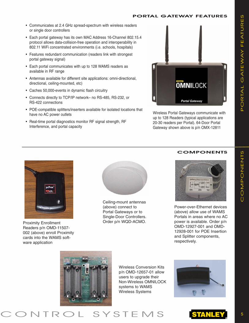
• Communicates at 2.4 GHz spread-spectrum with wireless readers or single door controllers
• Each portal gateway has its own MAC Address 16-Channel 802.15.4protocol allows data-collision-free operation and interoperability in 802.11 WiFi concentrated environments (i.e. schools, hospitals)
• Features redundant communication (readers link with strongest portal gateway signal)
• Each portal communicates with up to 128 WAMS readers as available in RF range
• Antennas available for different site applications: omni-directional, directional, ceiling-mounted, etc)
• Caches 50,000-events in dynamic flash circuitry
• Connects directly to TCP/IP network– no RS-485, RS-232, or RS-422 connections
• POE-compatible splitters/inserters available for isolated locations thathave no AC power outlets
• Real-time portal diagnostics monitor RF signal strength, RFInterference, and portal capacity
PORTAl gATEwAY FEATURES
COmPONENTS
Wireless Portal Gateways communicate withup to 128 Readers (typical applications are20-30 readers per Portal). 64-Door PortalGateway shown above is p/n OMX-12811
Proximity EnrollmentReaders p/n OMD-11507-002 (above) enroll Proximitycards into the WAMS soft-ware application
Power-over-Ethernet devices(above) allow use of WAMSPortals in areas where no ACpower is available. Order p/nOMD-12927-001 and OMD-12928-001 for POE Insertionand Splitter components,respectively.
Wireless Conversion Kitsp/n OMD-12657-01 allowusers to upgrade their Non-Wireless OMNILOCKsystems to WAMSWireless Systems
CO
MP
ON
EN
TS

6 WIRELESS ACCESS
SY
STEM
R
EQ
UIR
EM
EN
TS SYSTEm REQUIREmENTS
The OMNILOCK WAMS cylindrical, mortise, quick adapter, wall mount, exit device, or single door controller systems all program wirelessly via the Stanley OMNILOCK portal gateway(s) that plug into an existing or dedicated ethernet network. The Wirelessaccess management software runs on a Microsoft® Server 2003 platform that is connected to a network. The WAMS system can manage thousands of users in its powerful SQL database. If users want to enroll their existing magnetic or proximity cards, they musthave a magnetic card enroller or proximity card enrollment reader (not needed for keypad-code-only systems).
1) Wireless OMNILOCK administrator’s kit p/n OMS-12418-001 (includes software, admin Guide, quick user reference cards, and default programming proximity and/or magnetic cards)
2) Proximity Card Enrollment Reader p/n OMD-11507-002 (USB)
3) HID Proximity Cards, Keyfobs, and/or eProx Tags
4) 64-Reader Portal Gateway(s) that plug onto an existing or dedicated ethernet network p/n OMX-12811 (available only fromcertified Stanley OMNIlock dealers)
5) WAMS Readers and Locks (for the ordering sequence see page 10 – also examples below and on page 7)
Wireless exit device trims are available forPrecision, Sargent- Arrow, Von Duprin,Corbin-Russwin-Yale, Detex, and Dorma exitdevices. Available for both Standard or interchangeable core cylinders. The systemshown above is Stanley p/n QAXOM-7-14-PDVW-C-626-PH2-LHRB-W
To order backside antenna kit specify part number 3114285.
Note: The backside antenna can be used on Omnilock wireless locks that would benefit from the antenna being on the interior side of the door. One such application would be solid metal doors.
MountingBracket
BACkSIDE ANTENNA kIT
Cover/Antenna
Antenna JumperCable
Through bracketarea to
circuit board
CONTROL SYSTEMS 7
WA
LL M
OU
NT SY
STEM
wAll mOUNT SYSTEm
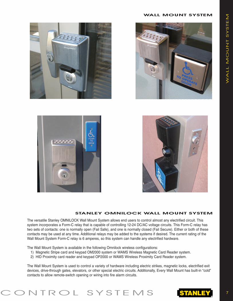
STANlEY OmNIlOCk wAll mOUNT SYSTEm
The versatile Stanley OMNILOCK Wall Mount System allows end users to control almost any electrified circuit. This system incorporates a Form-C relay that is capable of controlling 12-24 DC/AC voltage circuits. This Form-C relay hastwo sets of contacts: one is normally open (Fail Safe), and one is normally closed (Fail Secure). Either or both of thesecontacts may be used at any time. Additional relays may be added to the systems if desired. The current rating of theWall Mount System Form-C relay is 6 amperes, so this system can handle any electrified hardware.
The Wall Mount System is available in the following Omnilock wireless configurations:1) Magnetic Stripe card and keypad OM2000 system or WAMS Wireless Magnetic Card Reader system. 2) HID Proximity card reader and keypad OP2000 or WAMS Wireless Proximity Card Reader system.
The Wall Mount System is used to control a variety of hardware including electric strikes, magnetic locks, electrified exitdevices, drive-through gates, elevators, or other special electric circuits. Additionally, Every Wall Mount has built-in “cold”contacts to allow remote-switch opening or wiring into fire alarm circuits.

8 WIRELESS ACCESS
WIR
ELESS IN
STA
LLA
TIO
N D
IA
GR
AM
wIRElESS INSTAllATION DIAgRAm
Wall Mount Gate Mount Wireless Entrance

9 CONTROL SYSTEMS
HO
W TO
O
RD
ER
Ordering Example:1. Select Series (45HOM) 45HOM2. Select Cylinder Core Housing (0,7) 45HOM-73. Select Function Code (DV, TV) page 11 45HOM-7-DV4. Select Lever Style (3, 14, 15, 16) page 11 45HOM-7-DV-155. Select Trim Style (MDVW, KW, MSW, PDVW,PHW) 45HOM-7-DV-15-PDVW6. Select Rose Style (H) page 11 45HOM-7-DV-15-PDVW-H7. Select Housing Finish {B (black), G (grey), C (chrome)} 45HOM-7-DV-15-PDVW-H-C8. Select Lock Trim Finish (612, 613, 626, 690) page 11 45HOM-7-DV-15-PDVW-H-C-6269. Select Door Hand (RH, RHRB, LH or LHRB) 45HOM-7-DV-15-PDVW-H-C-626-RH10. Select Options {(DSR, KOS, LSM, Thick Door (specify 45HOM-7-DV-15-PDVW-H-C-626-RH-W
Thickness), W (weatherized –20 to +54C)}
NOTE: The above example is for a Wireless 45H Mortise Lock, With SFIC Core prep (no core included), LatchNon-deadbolt, Contour Angle Lever Style, Proximity Dual Validation, H Rose size, Chrome Housing, `626 Finish, Right-handed, and Weatherized.
Ordering Example:1. Select Backset (93KOM 2-3/4”, 94KOM 3-3/4”, 95KOM 5”) 93KOM2. Select Core Housing (0 Non-Best, 7 Best IC with no core) 93KOM-73. Select Function Code (DV with key) page 11 93KOM-7-DV4. Select Lever Style (14, 15, 16) page 11 93KOM-7-DV-145. Select Trim Style (MDVW, KW, MSW, PDVW,PHW) 93KOM-7-DV-14-PDVW6. Select Housing Finish {B (black), G (grey), C (chrome)} 93KOM-7-DV-14-PDVW-B7. Select Strike Package (STK– standard, S3– ANSI) page 11 93KOM-7-DV-14-PDVW-B-S38. Select Lock Trim Finish (612, 613, 626, 690) page 11 93KOM-7-DV-14-PDVW-B-S3-6269. Select Options {DSR, W (weatherized –20 to +54C), 93KOM-7-DV-14-PDVW-B-S3-626-DSR-W
COR, MED, SAR, SCH, YAL, SCHRC– 14 and 15 lever only}
NOTE: The above example is for a Wireless 93K Cylindrical Lock, With SFIC Core prep (no core included), with Key, Curved with Return Lever Style, Proximity Dual Validation, Black Housing, ANSI Strike, 626 Finish, with Door Switch Monitor and REX options and the Weatherized option.
Ordering Example:1. Select Series (OMEM) OMEM2. Select Lockset Type (C– Cylindrical, M– Mortise) OMEM-C3. Select Trim Style (MDVW, PDVW) OMEM-C-PDVW4. Select Housing Finish {B (black), G (grey), C (chrome)} OMEM-C-PDVW-C5. Select Options (W- weatherized –20 to +54C) OMEM-C-PDVW-C-W
NOTE: The above example is for a Wireless Electronic Module for a Cylindrical lock, with Proximity DualValidation, Satin Chrome Housing, and Weatherized.
HOw TO ORDER:
45HOm mORTISE lOCkINg SYSTEmS
HOw TO ORDER:
93kOm CYlINDRICAl lOCkINg SYSTEmS
HOw TO ORDER:
OmEm ElECTRONIC mODUlES

10 WIRELESS ACCESS
HO
W TO
O
RD
ER
Ordering Example:1. Select Series (OMWMS) OMWMS2. Select Core Housing (BE– Best 5E Cylinder NOT included, it OMWMS-BE
must be ordered separately– p/n 5E7A1-C1-14-3-R-360-626)3. Select Trim Style (MDVW, PDVW) OMWMS-BE-MDVW4. Select Housing Finish {B (black), G (grey), S (chrome)} OMWMS-BE-MDVW-G5. Select Options (W- weatherized –20 to +54C) OMWMS-BE-MDVW-G-W
NOTE: The above example is for a Wireless Wall Mount System, with a keyed Best 5E Utility Cylinder Magnetic Card Dual Validation, Grey Electronic Housing, and Weatherized.
Ordering Example:1. Select Series (QASOM) QASOM2. Select Trim Style (MDVW, PDVW) QASOM-PDVW3. Select Housing Finish {B (black), G (grey)} QASOM-PDVW-B4. Select Options (W- weatherized –20 to +54C, IC– for IC QASOM-PDVW-B-IC
Schlage locks, STD– for non-IC Schlage locks)
NOTE: The above example is for a Wireless Quick Adapter, Proximity Card Dual Validation, Black ElectronicHousing, and with driver for existing Schlage IC-core lockset.
HOw TO ORDER:
OmwmS wAll mOUNT SYSTEmS
HOw TO ORDER:
QASOm QUICk ADAPTER for SElECTED SCHlAgE D-SERIES
AND Al SERIES lOCkS
HOw TO ORDER:
QAXOm QUICk ADAPTERS FOR EXIT DEVICES
Ordering Example:1. Select Series (QAXOM) QAXOM2. Select Cylinder Housing (0- Non-IC, 7– Best IC no core) QAXOM-73. Select Lever Style (14 curved return, 15 contour angle return)
page 11 QAXOM-7-144. Select Trim Style (MDVW, KW, MSW, PDVW,PHW) QAXOM-7-14-PDVW5. Select Housing Finish {B (black), G (grey), C (chrome)} QAXOM-7-14-PDVW-C6. Select Lever Finish (612, 613, 626) page 11 QAXOM-7-14-PDVW-C-6267. Select Adapter Plate (CY1– Corbin-Russwin/Yale, QAXOM-7-14-PDVW-C-626-PH2
PH2– Precision, SA7, 8, 9– Sargent Series, VD8– Von Duprin 98/99 EO, VD9– Von Duprin 98/99F)
8. Select Door Hand (RHRB, LHRB) QAXOM-7-14-PDVW-C-626-PH2-LHRB9. Select Options {SCH– Schlage non-IC, (Thick Door (specify QAXOM-7-14-PDVW-C-626-PH2-LHRB-W
Door Thickness), W (weatherized –20 to +54C)}
NOTE: The above example is for a Wireless Exit Device Quick Adapter, Best IC Core, Curved Return lever, Proximity Card Dual Validation, Chrome Electronic Housing, 626 Lever Finish, with Precision APEX Adapter Kit, Left-Hand Reverse Bevel, and Weatherized (see page 6 for an example of this system).

Cylindrical #15
Mortise #14Mortise #3
TVDeadbolt with key override
Latchbolt operated by: • Outside key • Outside lever - unless locked by internal motor drive mechanism • Inside leverLatchbolt deadlocked by: • Auxiliary latchDeadbolt operated by: • Outside key • Inside turn knob • Outside lever when lever is unlocked by internal motor drive mechanism (retracts only) • Inside lever (retracts only)Outside lever locked and unlocked by: • Internal motor drive mechanism operated by time-activated elect- ronic signal or by valid card/PIN Inside lever is always unlocked
DVLatchbolt withkey override
Latchbolt operated by: • Outside key • Outside lever - unless locked by internal motor drive mechanism • Inside leverLatchbolt deadlocked by: • Auxiliary latchOutside lever locked by: • Internal motor drive mechanism operated by time-activated electronic signal or by valid card/PINOutside lever unlocked by: • Internal motor drive mechanism operated by time-activated elect- ronic signal or by valid card/PINInside lever is always unlocked
Cylindrical #14
612-satin bronze,clear coated
613-oxidized satinbronze, oil rubbed
626-satin chromium plated
690-dark bronze,powder coated
Mortise #16Mortise #15
Cylindrical #16
8KS2 Strike (Standard)Dimension: Conforms to ANSI A115.2 for 1 3/8"doors (2 3/4" x 1 1/8" with curved lip and box).To order: (with unit) designate “STK”.
To order: (without unit) designate 8KS2 + finish.
8KS3 StrikeDimension: Conforms to ANSI A115.2 for 1 3/4" doors (4 7/8" x 1 1/8" with curved lip).To order: (with unit) designate “S3”.
To order: (without unit) designate 8KS3 + fin ish.
11 CONTROL SYSTEMS
MO
RTISE FU
NC
TIO
NSmORTISE FUNCTIONS
LEVER STYLES
LEV
ER
STY
LES
FIN
ISH
ES
STRIKES
STR
IK
ES
MISCELLANEOUS – FINISHES

WIR
ELESS A
CC
ESS C
ON
TR
OL SY
STEM
S
Stanley Security Solutions, Inc.6161 E. 75th Street Indianapolis, Indiana 46250
© 2010 Stanley Security Solutions, Inc. • www.stanleysecuritysolutions.com 10M 210 BAS038