Embed Size (px)
Citation preview

Wired/Wireless Multi-media interface
WiMi6200 User’s Manual (v1.4)
WiMi6200 User’s Manual
1
Precautions for Safety & Protection of WiMi System
We appreciate you purchasing the WiMi6200.
Before installing the product, please read the following carefully.
Make sure you turn off the power before installing the WiMi6200.
Do not install under the direct sunlight or in dusty areas.
Make sure you use the product within the temperature and humidity specified in the
specification.
Do not operate the product in presence of vibration or strong magnetic fields.
Do not put electrically conducting materials in the ventilation hole.
Do not open the top cover of the product. It may cause a failure or electric shock from the
components.
To prevent the unit from overheating, make sure you keep the ventilation holes at the top
least 10cm from any other object. Also allow air underneath the unit and do not obstruct vent
holes.
Make sure the main power voltage is correct (220V/110V) before connecting the power
adapter supplied in the box (12V DC output).
Do not obstruct ventilation holes above and below the system. Rubber feet are provided to
allow air flow below the enclosure, in addition to outlet holes at the top of the enclosure.
Do not connect video source device to the WiMi6200R and video display to the WiMi6200T.
Do not turn on the power before assembling every antenna into the WiMi system. Power on
without connection of antenna to the WiMi system can be a cause of damaging the radio
module in the WiMi system.
There may be a possibility of radio interference with other Wi-Fi devices using this WiMi
system.

WiMi6200 User’s Manual
2
Document Revision History
Revision Date Description
v1.0 February 10, 2014 Initial release of WiMi6200 User ’s Manual v1.0 based on new
firmware version303.01.3.
v1.1 April 24, 2015
Added Wi-Fi Ch. 165 (5825MHz) at the frequency table
Added frequency selection table for EU countries, Table 2.1 and
Table 4.1
v1.2 July 1, 2015 Added frequency selection table for Japanese customers, Table 2.2
and Table 4.2
v1.3 August 25, 2015 Updated frequency selection table for FCC/CE/Telec
v1.4 September 25, 2015 Updated frequency selection table for CE

WiMi6200 User’s Manual
3
1. Introduction
1.1 About this Manual
This user manual provides step-by-step instructions for installing and using WiMi6200. The
safeguards incorporated into this unit will protect you if you observe the following
procedures for installation, use, and servicing. The wireless version, WiMi6200TW and
WiMi6200RW, includes all the functions of WiMi6200T and WiMi6200R LAN version. So, all
the explanations about the WiMi6200T and WiMi6200R are applied to WiMi6200TW and
WiMi6200RW system, also.
1.2 Overview
WiMi6200T/R is a Full HD 1920 x1080 at 60 frames/second encoder/decoder designed to
be used for various streaming applications where high quality HD-SDI video output needs
to be sent over Wi-Fi or an IP network at low data rates. Video resolutions from PAL and
NTSC up to 3G-SDI are supported as well as stereo audio. In combination with the
WiMi6200R decoder unit the WiMi6200T can additionally stream video at extremely low
latencies (delay), typically 80ms end-to-end. And the WiMi6200T can be used to for real-
time video streaming server for software decoder on the PC without WiMi6200R hardware
decoder. The WiMi6200T/R provides talk-back audio port together with the virtual 2-way
serial cable function, RS-422. Video and audio data are transmitted via a 10/100 Ethernet
port or Wi-Fi. Power is supplied by battery or the 110/240V AC to 12V DC converter
supplied. Below diagrams show the examples of the WiMi6200T and WiMi6200R.

WiMi6200 User’s Manual
4

WiMi6200 User’s Manual
5
WiMi6200 User’s Manual
6
1.3 Features
Video
High performance SD/HD/3G-SDI transmission over Wi-Fi or Ethernet LAN (IP)
H.264 encoding/decoding engine: Baseline profile level 4.2 with de-interlacing
Supports both interlacing and progressive input streams
Full HD encoding up to 1920x1080p60
Supporting streaming server function on both WiMi6200T and WiMi6200R
Very low encode/decode end-to-end latency in 1080i59.94 HD: 70ms ~ 80ms
Single video stream + stereo audio
SDI/HD-SDI/3G-SDI supported for PAL, NTSC and full HD video
Supports DTV Standards
• SMPTE 244, BT601 (NTSC): 525i59.94
• IEC61179-5, BT601 (PAL): 625i50
• SMPTE 296M: 720p23.98, 720p24, 720p25, 720p30, 720p50, 720p59.94, 720p60
• SMPTE 274M: 1080i50, 1080i59.94, 1080i60, 1080PsF23.98,1080PsF24, 1080PsF25, 1080PsF29.97, 1080PsF30, 1080p23.98, 1080p24, 1080p25, 1080p29.97, 1080p30, 1080p50, 1080p59.94, 1080p60
Wide range of video encoding and transmission rates : 100kbps ~ 30Mbps
Various error resiliency : Variable GOP size, random intra-refresh, contiguous intra-refresh or I-frame forcing
Audio
SD/HD/3G-SDI embedded audio
Mini-stereo phone jack in and out for analog stereo audio
Analog stereo audio: 48kHz sampling with 16 bit ADC
Wireless talk-back audio from TX to RX and from RX to TX with 8kHz sampling and 16bit ADC that eliminates additional wireless audio equipment
Network
Wireless Output for Audio/Video : Supporting IEEE 802.11n/5GHz
Wide radio coverage up to 900m (3,000ft) with 12Mbps at line of sight
Ethernet port for audio/video transmission: Ethernet LAN (10/100 BASE-TX, Cat.5e UTP cable)
1 TX to 1 RX connection or 1 TX to 4 RX connections on wireless mode

WiMi6200 User’s Manual
7
One to one connection & one to many connection on the Ethernet LAN mode
Multi-casting and simulcast modes to both the WiMi6200R and software decoder on PC
Various standard protocols supported : RTP/UDP/IP, Multicast, DHCP, HTTP, RTSP,
RTSP streaming server or MPEG-TS streaming device over Wi-Fi or LAN port on the WiMi6200T
RTSP/MPEG2TS streaming relay server over LAN port on the WiMi6200R
RS-422 serial port for relaying bidirectional external control signals
User Interface
Internet Explorer/Chrome web browser for changing system configurations or firmware upgrade
USB for factory reset, IP configuration or firmware upgrade without using PC Web browser (version_300.00 later)
Operating conditions
0 to +40oC ambient operating temperature
DC 12V input (6.6V ~ 16V)
Reliability
Reliable embedded system
System recovery utilizing dual watch-dog functions

WiMi6200 User’s Manual
8
1.4 Package Contents
1.4.1 Wireless and LAN (WiMi6200TW/WiMi6200RW)
- WiMi6200TW x 1, WiMi6200RW x 1
WiMi6200TW WiMi6200RW
- AC/DC Power adapter (mini XLR) x 1 (option)
- Antenna x 6

WiMi6200 User’s Manual
9
1.4.2 LAN only (WiMi6200T/WiMi6200R)
- WiMi6200TW x 1, WiMi6200RW x 1
WiMi6200TW WiMi6200RW
- AC/DC Power adapter (mini XLR) x 2

WiMi6200 User’s Manual
10
1.5 Detail functions of WiMi6200T (Encoder/Transmitter)
Video Input
SD-SDI, HD-SDI or 3G-SDI
Pass-through SDI output port
Audio Inputs
SD-SDI/HD-SDI/3G-SDI: Embedded audio
Analog stereo audio for wireless intercom: 8kHz sampling with 16-bit resolution
Audio Output (wireless intercom )
Analog Stereo Audio: 8kHz sampling with 16-bit resolution per channel
Encoding of Moving Pictures
H.264 (MPEG-4 parts10 : AVC)
Baseline Profile with Level 4.2 (up to 1920 x 1080p60)
Encoding rate of max. 30Mbps for 1080p60/50
Selection of encoding rate through the front panel of the system on the fly
Video downscaling function:
• 1080i60/59.94 480i60/59.94
• 1080p60/59.94 720p60/59.94 or 480p60/59.94
• 720p60/59.94 480p60/59.94
Wireless Interface for Audio/Video
Supporting IEEE802.11n (5 GHz)
MIMO interface (3x3)
Coverage: ~ 900m (3,000 ft) at line of sight (LOS)
Selection of frequency through the front panel of the system on the fly
Ethernet Interface for Audio/Video
10/100 BASE-TX, Cat.5e UTP cable (100~150m)
Multicasting over Ethernet LAN environment
RTSP streaming server & MPEG-TS streaming
RTSP client: VLC media player on the PC, Ace Player for IOS, BS Player for Android
MPEG-TS streaming: H.264 NAL video and 48kHz linear PCM audio only
USB: Factory reset, IP configuration or firmware upgrade without Web browser on PC
RS422 serial port for bi-directional external control
Inter-operable with WiMi4000R and WiMi6400R (version 303.00.3 or later) over LAN

WiMi6200 User’s Manual
11
1.5.1 Front and Rear panel of WiMi6200T
Front View
Item Component Description
1 PWR (LED) This LED shows the power status
2 HD-SDI (LED)
This LED shows the SDI video input signal status. It will blink
when there is no SDI video signal input, and will light when SDI
video signal is engaged.
3 Link (LED)
This LED shows the Wi-Fi link status. It will blink when there is
no wireless connection between the TX and RX, and will light
when the wireless connection was established.
4 Encoding Rate Selection of the video encoding rate. The change of selection
will be effective on the fly (Table-1).
5 Wi-Fi Channel
Selection of Wi-Fi channel and SSID. The change of selection will
be effective on the fly (Table-4). The setting of these pins must
be same with the setting of WiMi6200RW transmitter.
6 RS-422 RS-422 interface (Below Diagram)
7 LAN RJ-45 Ethernet LAN port
Rear View
Item Component Description
1 SDI In SD/HD/3G-SDI video input/embedded audio input
2 SDI Loop out SDI Looped output port (Audio embedded)

WiMi6200 User’s Manual
12
3 Aux. Audio in Talk-back audio (Intercom) stereo input (Analog)
4 Aux. Audio out Talk-back audio (Intercom) stereo output (Analog)
5 USB Factory reset, IP configuration
6 Power Switch Power switch
7 PWR Mini XLR DC power input (6.6V ~ 16V)
Table-1 Selection of Encoding Rate on the front panel of the WiMi6200T
SW Position Encoding rates
12 Mbps
20 Mbps
25 Mbps
Arbitrary encoding rate controlled by Web page
Table-2 Selection of Wi-Fi Ch. and SSID on the front panel of the WiMi6200T
for North America (FCC)
SW Position
SSID Wi-Fi Ch. (Frequency)
SW Position
SSID Wi-Fi Ch. (Frequency)
WiMi6200_00 36
(5180 MHz)
WiMi6200_08 165
(5825 MHz)
WiMi6200_01 40
(5200 MHz)
WiMi6200_09 48
(5240 MHz)
WiMi6200_02 44
(5220 MHz)
WiMi6200_10 149
(5745 MHz)
WiMi6200_03 48
(5240 MHz)
WiMi6200_11 153
(5765 MHz)
WiMi6200_04 149 (5745 MHz)
WiMi6200_12 157 (5785 MHz)
WiMi6200_05 153
(5765 MHz)
WiMi6200_13 161 (5805 MHz)
WiMi6200_06 157
(5785 MHz)
WiMi6200_14 165
(5825 MHz)
WiMi6200_07 161
(5805 MHz)
LAN Mode
WiMi6200 User’s Manual
13
Table-2.1 Selection of Wi-Fi Ch. and SSID on the front panel of the WiMi6200T
for EU countries (CE)
SW Position
SSID Wi-Fi Ch. (Frequency)
SW Position
SSID Wi-Fi Ch. (Frequency)
WiMi6200E_00 36
(5180 MHz)
WiMi6200E_08 116
(5580 MHz)
WiMi6200E_01 40 (5200 MHz)
WiMi6200E_09 132 (5660 MHz)
WiMi6200E_02 44 (5220 MHz)
WiMi6200E_10 136 (5680 MHz)
WiMi6200E_03 48
(5240 MHz)
WiMi6200E_11 140
(5700 MHz)
WiMi6200E_04 100 (5500 MHz)
WiMi6200E_12 104 (5520 MHz)
WiMi6200E_05 104
(5520 MHz)
WiMi6200E_13 108 (5540 MHz)
WiMi6200E_06 108
(5540 MHz)
WiMi6200E_14 112
(5560 MHz)
WiMi6200E_07 112 (5560 MHz)
LAN Mode
WiMi6200 User’s Manual
14
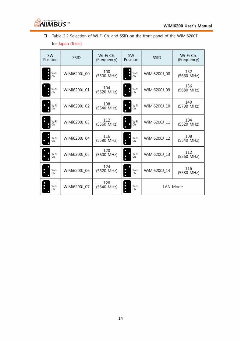
Table-2.2 Selection of Wi-Fi Ch. and SSID on the front panel of the WiMi6200T
for Japan (Telec)
SW Position
SSID Wi-Fi Ch. (Frequency)
SW Position
SSID Wi-Fi Ch. (Frequency)
WiMi6200J_00 100
(5500 MHz)
WiMi6200J_08 132
(5660 MHz)
WiMi6200J_01 104
(5520 MHz)
WiMi6200J_09 136
(5680 MHz)
WiMi6200J_02 108
(5540 MHz)
WiMi6200J_10 140
(5700 MHz)
WiMi6200J_03 112
(5560 MHz)
WiMi6200J_11 104
(5520 MHz)
WiMi6200J_04 116 (5580 MHz)
WiMi6200J_12 108 (5540 MHz)
WiMi6200J_05 120
(5600 MHz)
WiMi6200J_13 112 (5560 MHz)
WiMi6200J_06 124
(5620 MHz)
WiMi6200J_14 116
(5580 MHz)
WiMi6200J_07 128
(5640 MHz)
LAN Mode
WiMi6200 User’s Manual
15
1.6 Detail functions of WiMi6200R (Decoder/Receiver)
Wireless Interface for Audio/Video
Supporting IEEE802.11n (5 GHz)
MIMO interface (3x3)
Coverage: ~ 900m (3,000 ft) at line of sight (LOS)
Multiple receiver operation against one WiMi6200TW transmitter
• SYS-ID: Identify the #1, #2, #3 and #4 at wireless mode
Ethernet for Audio/Video Input/Output
10/100 BASE-TX, Cat.5e UTP cable (100~150m)
Multicasting over Ethernet LAN environment
Decoding of Moving Pictures
H.264 (MPEG-4 Parts10: AVC)
Baseline Profile with Level 4.2 (up to 1920 x 1080p60) with de-interlacing
Video Output
SD-SDI (480i60), HD-SDI (1080i60) or 3G-SDI (1080p60)
Audio Outputs
SD-SDI/HD-SDI/3G-SDI: Embedded audio
Analog stereo audio output: 48kHz sampling with 16-bit resolution
Analog stereo audio output for talk-back audio: 8kHz sampling with 16-bit
Audio Input (wireless intercom )
Analog stereo audio input for talk-back audio: 8kHz sampling with 16-bit
RTSP relay streaming server with same encoding rate of the WiMi4000T/6200T/6400T
RTSP client: VLC media player on the PC or Ace Player for IOS/BS Player for Android through the wireless AP
USB: Factory reset, IP configuration or firmware upgrade without Web browser on PC
RS422 serial port for bi-directional external control
Inter-operable with WiMi4000T and WiMi6400T (version 303.00.3 or later) over LAN
WiMi6200 User’s Manual
16
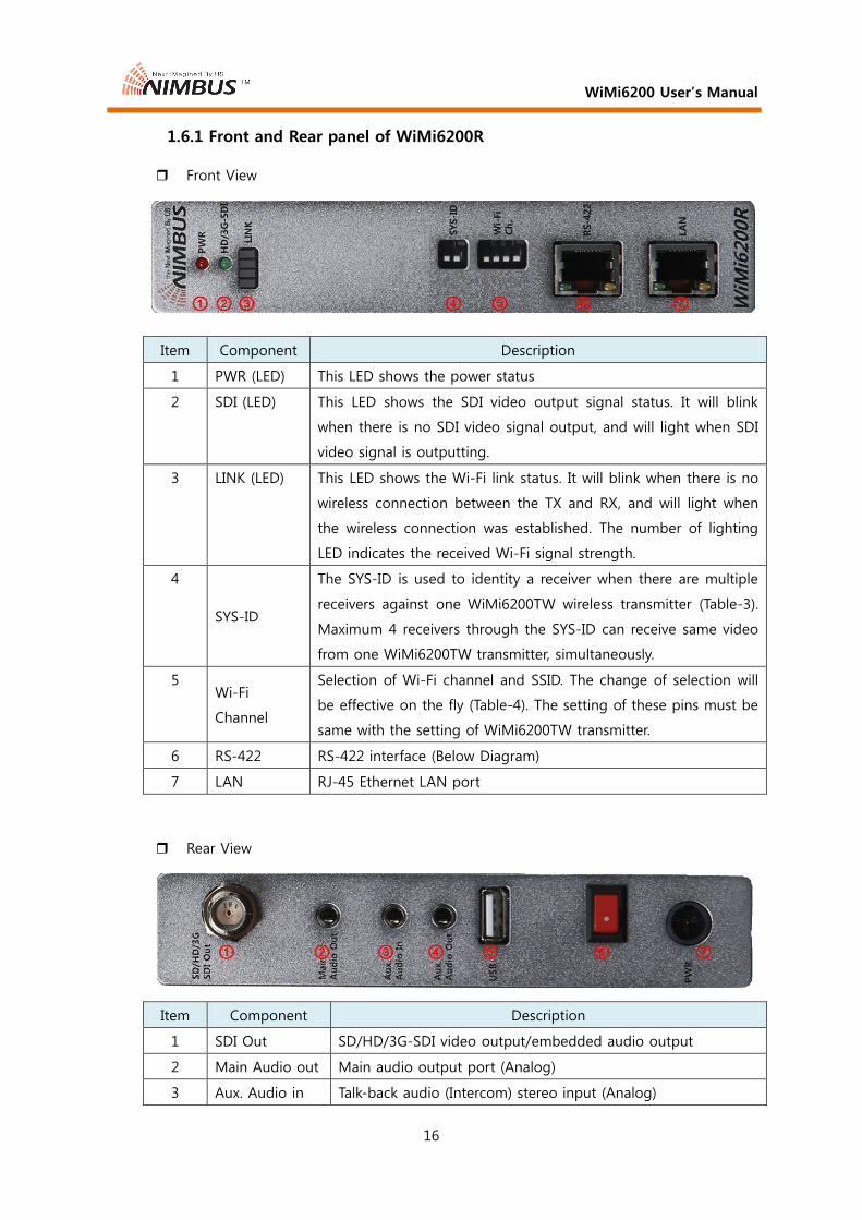
1.6.1 Front and Rear panel of WiMi6200R
Front View
Item Component Description
1 PWR (LED) This LED shows the power status
2 SDI (LED) This LED shows the SDI video output signal status. It will blink
when there is no SDI video signal output, and will light when SDI
video signal is outputting.
3 LINK (LED) This LED shows the Wi-Fi link status. It will blink when there is no
wireless connection between the TX and RX, and will light when
the wireless connection was established. The number of lighting
LED indicates the received Wi-Fi signal strength.
4
SYS-ID
The SYS-ID is used to identity a receiver when there are multiple
receivers against one WiMi6200TW wireless transmitter (Table-3).
Maximum 4 receivers through the SYS-ID can receive same video
from one WiMi6200TW transmitter, simultaneously.
5 Wi-Fi
Channel
Selection of Wi-Fi channel and SSID. The change of selection will
be effective on the fly (Table-4). The setting of these pins must be
same with the setting of WiMi6200TW transmitter.
6 RS-422 RS-422 interface (Below Diagram)
7 LAN RJ-45 Ethernet LAN port
Rear View
Item Component Description
1 SDI Out SD/HD/3G-SDI video output/embedded audio output
2 Main Audio out Main audio output port (Analog)
3 Aux. Audio in Talk-back audio (Intercom) stereo input (Analog)

WiMi6200 User’s Manual
17
4 Aux. Audio out Talk-back audio (Intercom) stereo output (Analog)
5 USB Factory reset, IP configuration
6 Power Switch Power switch
7 PWR Mini XLR DC power input (6.6V ~ 16V)
Table-3 Selection of SYS-ID on the front panel of the WiMi6200R
SW Position Receiver System Identifier
SLAVE1
SLAVE2
SLAVE3
SLAVE4
Table-4 Selection of Wi-Fi Ch. and SSID on the front panel of the WiMi6200R
for North America (FCC)
SW Position SSID
Wi-Fi Ch. (Frequency)
SW Position SSID
Wi-Fi Ch. (Frequency)
WiMi6200_00 36
(5180 MHz)
WiMi6200_08 165
(5825 MHz)
WiMi6200_01 40 (5200 MHz)
WiMi6200_09 48 (5240 MHz)
WiMi6200_02 44 (5220 MHz)
WiMi6200_10 149 (5745 MHz)
WiMi6200_03 48
(5240 MHz)
WiMi6200_11 153
(5765 MHz)
WiMi6200_04 149
(5745 MHz)
WiMi6200_12 157
(5785 MHz)
WiMi6200_05 153
(5765 MHz)
WiMi6200_13 161
(5805 MHz)
WiMi6200_06 157
(5785 MHz)
WiMi6200_14 165
(5825 MHz)
WiMi6200_07 161 (5805 MHz)
LAN Mode

WiMi6200 User’s Manual
18
Table-4.1 Selection of Wi-Fi Ch. and SSID on the front panel of the WiMi6200R
for EU countries (CE)
SW Position
SSID Wi-Fi Ch. (Frequency)
SW Position
SSID Wi-Fi Ch. (Frequency)
WiMi6200E_00 36 (5180 MHz)
WiMi6200E_08 116 (5580 MHz)
WiMi6200E_01 40
(5200 MHz)
WiMi6200E_09 132
(5660 MHz)
WiMi6200E_02 44
(5220 MHz)
WiMi6200E_10 136
(5680 MHz)
WiMi6200E_03 48
(5240 MHz)
WiMi6200E_11 140
(5700 MHz)
WiMi6200E_04 100
(5500 MHz)
WiMi6200E_12 104
(5520 MHz)
WiMi6200E_05 104 (5520 MHz)
WiMi6200E_13 108 (5540 MHz)
WiMi6200E_06 108 (5540 MHz)
WiMi6200E_14 112 (5560 MHz)
WiMi6200E_07 112
(5560 MHz)
LAN Mode

WiMi6200 User’s Manual
19
Table-4.2 Selection of Wi-Fi Ch. and SSID on the front panel of the WiMi6200R
for Japan (Telec)
SW Position
SSID Wi-Fi Ch. (Frequency)
SW Position
SSID Wi-Fi Ch. (Frequency)
WiMi6200J_00 100
(5500 MHz)
WiMi6200J_08 132
(5660 MHz)
WiMi6200J_01 104
(5520 MHz)
WiMi6200J_09 136
(5680 MHz)
WiMi6200J_02 108
(5540 MHz)
WiMi6200J_10 140
(5700 MHz)
WiMi6200J_03 112
(5560 MHz)
WiMi6200J_11 104
(5520 MHz)
WiMi6200J_04 116 (5580 MHz)
WiMi6200J_12 108
(5540 MHz)
WiMi6200J_05 120 (5600 MHz)
WiMi6200J_13 112
(5560 MHz)
WiMi6200J_06 124
(5620 MHz)
WiMi6200J_14 116
(5580 MHz)
WiMi6200J_07 128
(5640 MHz)
LAN Mode

WiMi6200 User’s Manual
20
1.7 System Specifications
Video Compression H.264 Baseline Profile Level 4.2 with de-interlacing
System Latency 70 ~ 90 millisecond delay between Transmitter and Receiver
Digital Video In/Out SD-SDI, HD-SDI, 3G-SDI
Video Port TX: SDI input and looped output, RX: SDI output
Supported Video
Resolutions
SMPTE 244 480i59.94 (NTSC), 480i60 (861-D)
IEC61179-5 576i50 (PAL)
SMPTE 296M 720p23.98, 720p24, 720p25, 720p29.97, 720p30, 720p50, 720p59.94,
720p60
SMPTE 274M 1080i50, 1080i59.94, 1080i60, 1080PsF23.98,1080PsF24, 1080PsF25, 1080PsF29.97, 1080PsF30, 1080p23.98, 1080p24, 1080p25, 1080p29.97,1080p30, 1080p50,
1080p59.94, 1080p60
SDI Compliance
SMPTE 259M
BT.656 SDTV Digital Signal/Data Serial Digital Interface
SMPTE 292M
BT.1120 1.5Gb/s Signal/Data Serial Digital Interface
SMPTE 425M
(option) 3Gb/s Signal/Data Serial Digital Interface
SMPTE 299M 16bit Digital Audio Format for SMPTE 292M SMPTE 352M Video Payload Identification for Digital Interfaces
Main Digital Audio
In/Out TX/RX SDI embedded audio: 48kHz 16-bit stereo linear PCM
Main Analog Audio
Out RX 48kHz 16-bit stereo linear PCM with mini stereo phone output jack
Talk-Back Analog
Audio In/Out RX/TX 8kHz 16-bit stereo linear PCM with mini stereo phone input/output
jack
Radio Power Aggregate Power: 150mW (22dBm), 50mW (17dBm)/antenna
Radio standard IEEE 802.11a/n: OFDM
Frequencies 5.15~5.85 GHz
Antenna 3T x 3R MIMO, 3 antennas per WiMi6200TW/WiMi6200RW
Ethernet LAN 10/100 BASE-TX, RJ-45 jack
External Control Full duplex RS422 serial port

WiMi6200 User’s Manual
21
USB Factory reset, IP configuration or firmware upgrade without PC
Power Input/
Consumption DC 6.6V - 16V/ Wireless version: 12 Watts, Ethernet only version: 8 Watts
Dimensions
(H x W x D) Ethernet 155 x 30 x 118 (mm), Including stand: 164 x 70 x 118 (mm) Wireless 323 x 30 x 118 (mm), Including mount plates: 315 x 60 x 118 (mm)
Weight (g) Ethernet Including stand: 360g Wireless 420g, Including mount plate: 630g
Operating
Temperature Operating from 0°C ~ 50°C

WiMi6200 User’s Manual
22
1.8 Video Format Supported: DTV
Below table shows the resolutions and frame rates supported by the WiMi6200.
Video
Standard Resolutions
Transmitter Receiver SDI SDI
DTV Format
720 x 480 I59.94 (NTSC) O O 720 x 576 I50 (PAL) O O 1280 x 720 P60/59.94 O O 1280 x 720 P50 O O 1280 x 720 P30/29.97 O O 1280 x 720 P25 O O 1280 x 720 P24/23.98 O O 1920 x 1080 I50 O O 1920 x 1080 I60/59.94 O O 1920 x 1080 P24/23.98 O O 1920 x 1080 PsF24/PsF23.98 O O 1920 x 1080 P25 O O 1920 x 1080 P30/29.97 O O 1920 x 1080 PsF30/PsF29.97 O O 1920 x 1080 P50 O O 1920 x 1080 P60/59.94 O O 1920 x 1080 PsF60/PsF59.94 O O

WiMi6200 User’s Manual
23
1.9 Quick Start Guide
The WiMi6200T is a high quality 1080P60 video and audio encoder. WiMi6200T
compresses video using H264 standards, and streams this compressed signal over an IP
network via Ethernet. Using the WiMi6200R decoder unit will allow the IP network stream
to be decoded and converted back to video plus audio. Alternatively a software decoder
such as VLC player may be used to decode the IP network stream generated by the
WiMi6200T or WiMi6200R.
Quick Start 1 - Power up and streaming video
1) Remove the WiMi6200T and WiMi6200R from its packaging. The WiMi6200T or
WiMi6200R comes with a 12 volt power converter (120/220/240V AC to 12 VDC).
The WiMi6200TW needs the V-mount or Gold mount battery that will supply the
power to the system.
2) Wireless operation:
A. Set the DIP switch of ENC Rate to position and DIP switch of Wi-Fi Ch.
to position on the front panel of WiMi6200TW. And set the DIP switch
of Wi-Fi Ch. to position on the front panel of WiMi6200RW.
B. Connect suitable video source to the HD-SDI input port on the WiMi6200T, and
connect the HD-SDI output port on the WiMi6200R to the appropriate HD-SDI
display device via 75 ohm SDI cables. Video resolution can be from PAL/NTSC
up to 1920 x1080 at 59.94 Hz or frames/second, HD-SDI or 3G-SDI.
C. Attach the V-mount/Gold mount battery to the WiMi6200TW, and connect the
12V DC plug into the 12V jack of the WiMi6200RW. Turn on WiMi6200TW,
WiMi6200RW, video source, and display.
3) LAN operation:
A. Prepare a Cat.5e LAN cable (not supplied), two HD-SDI cables (not supplied)
and suitable HD-SDI source (Video Camera or etc.)/HD-SDI display.
B. Connect one end of the LAN cable to the LAN port of the WiMi6200T and the
other end to the LAN port of the WiMi6200R. And connect suitable video
source to the HD-SDI input port on the WiMi6200T, and connect the HD-SDI
output port on the WiMi6200R to the appropriate HD-SDI display device via 75

WiMi6200 User’s Manual
24
ohm SDI cables. Video resolution can be from PAL/NTSC up to 1920 x1080 at
59.94 Hz or frames/second, HD-SDI or 3G-SDI.
C. Connect the 12V DC plug into the 12V jack of the WiMi6200T and WiMi6200R,
each. Turn on WiMi6200T, WiMi6200R, video source, and display.
4) 3x LEDs will blink for 5~6 seconds, and then one yellow LED (LINK) will blink for
35~37 seconds until the unit boots into its standby/ready condition.
5) After booting of the WiMi6200T, the green LED (HD-SDI) will blink until it detects the
video signal, and the yellow LED (LINK) will stop blinking after connection of the LAN
(Wi-Fi) link is established. The yellow LED on the RJ45 port of LAN will blink when
the transmitter starts to send A/V data in LAN mode.
6) After booting of the WiMi6200R, the green LED (HDMI) will blink until it outputs the
video signal to the display device, and the yellow LED (LINK) will stop blinking and
keep lighting after the connection from the WiMi6200T.
7) You can see the video on the display.
A full list of supported video formats was described in section 1.8 of this manual.
WiMi6200T + WiMi6200R are shipped with the following defaults:
- Enc. Rate on WiMi6200T is 12Mbps.
- SYS-ID on WiMi6200R is SLAVE1
- Wi-Fi Ch. and SSID of the 6200TW and 6200RW: Ch.157 with SSID of WiMi6200_03
- Factory default IP addresses are 192.168.0.161 (WiMi6200T) and 192.168.0.162
(WiMi6200R).
- Connection via LAN will allow video from the WiMi6200T to be streamed to the
WiMi6200R without any changes being made to the settings. Customers with both
units should test this configuration first. And then, you can change the video port on
the WiMi6200T and WiMi6200R via Select button or a web browser explained below
Quick Start 2.
- Customers with WiMi6200T encoder only should test with PC with some change
setting explained below Quick Start 2 and Quick Start 3.
Quick Start 2 - Connecting a web browser to adjust/ change settings.

WiMi6200 User’s Manual
25
The WiMi6200T/R has a web interface for configuration of all audio/video parameters,
network functions etc. Currently you have to use Internet Explorer or Chrome web browser
for this function.
Having connected the WiMi6200T to a video/audio source and 12V DC, next connect the
Ethernet port of WiMi6200T to an Ethernet L2 switch (L2 Hub), or to a PC directly using an
Cat.5e UTP cable (not supplied).
Connect a laptop or PC to the same network that the WiMi6200T is connected to. And,
change the IP address of PC to 192.168.0.xxx. Open a web browser and type the
192.168.0.161 on the URL field of the web browser. Then you can see the WiMi6200T web
page. All the same procedure will be applied to the WiMi6200R, except the IP address,
192.168.0.162.
Quick Start 3 - Video/audio streaming server for RTSP client (VLC player)
The WiMi6200T can be set to operate as a streaming server that sends video/audio to a
software decoder, such as the VLC player on the PC, Ace Player for IOS devices and BS
Player for Android devices.
To test software decoding using VLC player please follow these instructions:
1) Browse to the WiMi6200T IP address using web browser, such as the Internet
Explorer or Chrome.
2) On the Streaming Control page of the WiMi6200T, section 3.4.1.4, select RTP on the
Encapsulation pull down menu and select ON of the RTSP Server pull down menu.
Then press SUBMIT to activate these setting changes to RAM
3) If you wish to save this configuration to FLASH memory so that after next power up
these settings will be default, go to SAVE SETTINGS and click SAVE then confirm.
4) Execute the VLC player. Select Media(M) pull-down menu and select Open Network
Stream(N). Type “rtsp://192.168.0.161:8554/stream” (where 192.168.0.161 is the IP
address of the WiMi6200T) on the network URL field, and play. Please use the VLC
version 2.0 or later.
5) VLC will now decode the incoming RTSP stream from the WiMi6200T.
6) The delay of video on the VLC player can be controlled via network caching time.
Below capture shows this. ① Click the “Show more options” ② Reduce the
network-caching time to 100ms. This value should be changed to proper value

WiMi6200 User’s Manual
26
according to the network delay between the WiMi6200T and the PC on which the
VLC player is running. ③ Click the Play button.
7) If there is a WiMi6200R on the same network, the 6200R can decode video even
though the VLC player is decoding the live video on the PC.
Note) In some PC, the 1920x1080p60 resolution would not be able to be decoded
properly. In this case, you can see clean video if you change the input video resolution to
1280x720p60 or change the frame rate from 60Hz to 30Hz (1920x1080p30) via encoder
setting (Section 3.4.1.4)
Quick Start 4 - Streaming video to VLC player/set-top box with the MPEG-TS
The WiMi6200T can stream the live video/audio input toward the software decoder or
set-top box over IP network through the encapsulation of the video/audio data into the
MPEG Transport Stream (MPEG-TS).
1) On the Streaming Control page of the WiMi6200T, section 3.4.1.4, select TS2UDP on
the Encapsulation pull down menu, GOP on the Coding Mode pull down menu.
Then press SUBMIT to activate these setting changes to RAM
2) If you wish to save this configuration to FLASH memory so that after next power up
WiMi6200 User’s Manual
27
these settings will be default, go to SAVE SETTINGS and click SAVE then confirm.
3) Execute the VLC player. Select Media(M) pull-down menu and select Open Network
Stream(N). Enter “udp://@:1234/” in P2P mode, or enter “udp://@227.2.2.7:1234/”
(where 227.2.2.7 is the multicasting IP address of the WiMi6200T) in Multicast mode
on the network URL field, and play. Please use the VLC version 2.0 or later.
4) VLC will now decode the incoming MPEG-TS stream from the WiMi6200T.
5) The delay of video on the VLC player can be controlled via network caching time.
See previous page for control this.
Quick Start 5 – Multicasting over Wi-Fi
The WiMi6200TW can transmit the live video/audio to maximum 4 WiMi6200RW
receivers, simultaneously. Below shows a quick guide about how to configure it. The
multicast configuration will show the shorter radio distance than the point-to-point
configuration.
1) Set the “ENC rate” of the TX to 12Mbps (Section 1.5.1)
2) Set the “Streaming Mode” of TX to “Multicast” through web UI (Section 3.4.1.5)
3) 1 TX and 4 RXs must have the same SSID to communicate each other. Set “Wi-Fi Ch”
switch on both the TX and 4 RXs to same position (Section 1.5.1 and 1.6.1)
4) 4 RXs must be identified with different SYS-ID. Set “SYS-ID” switch on the RX #1 to
SLAVE1, RX #2 to SLAVE2, RX #3 to SLAVE3 and RX #4 to SLAVE4 position (Section
1.6.1)

WiMi6200 User’s Manual
28
2. Installation
2.1 Connection of video signal
WiMi6200T
Connect the video cable from the SDI/HD-SDI camera or other SDI/HD-SDI video source to the SDI video connector.
WiMi6200R
Connect the video/audio cable from the SDI/HD-SDI video connector to the display device.
2.2 Connection of Audio Signal
WiMi6200T
Audio input
Input HD-SDI port includes embedded digital audio data.
Aux. Audio In: Connect the mini stereo phone cable from microphone, microphone of the headset or other audio source to this jack. Analog audio input is converted to 8kHz 16-bit digital audio for transmitting to the Aux. Audio Out port of the WiMi6200R.
Aux. Audio Out: Connect the mini stereo phone cable from this jack to the speaker or headset. This analog audio output is the analog audio that is received from the Aux. Audio Out port of the remote WiMi6200T.
WiMi6200R
Audio output
Output HD-SDI port includes embedded digital audio data.
Main Audio Out: Connect the mini stereo phone cable from this jack to the speaker or to other audio input device. This analog audio output is converted from 48kHz 16-bit digital audio that is received from the embedded audio from the SDI port of the WiMi6200T.
Aux. Audio In: Connect the mini stereo phone cable from microphone, microphone of the headset or other audio source to this jack. Analog audio input is converted to 8 kHz 16-bit digital audio for transmitting to the Aux. Audio Out port of the WiMi6200T.
Aux. Audio Out: Connect the mini stereo phone cable from this jack to the speaker or headset. This analog audio output is the analog audio that is received from the Aux. Audio Out port of the remote WiMi6200R.

WiMi6200 User’s Manual
29
2.3 Network Connection
The video and audio data from WiMi6200T and WiMi6200R are transmitted and received through the standard Ethernet LAN.
WiMi6200T
Ethernet LAN
10/100 BASE-TX, Cat.5 UTP cable(100 ~ 150m)
Wireless LAN (WiMi6200TW)
Supporting IEEE802.11n (5GHz)
MIMO interface
Coverage : ~900m (3,000ft) at line of sight (LOS)
WiMi6200R
Ethernet LAN
10/100 BASE-TX, Cat.5 UTP cable
Wireless LAN (WiMi6200RW)
Supporting IEEE802.11n (5GHz)
MIMO interface
Coverage : ~450m (3,000ft) at line of sight (LOS)
2.4 Power Connection
The power cable or battery is connected and the power is on, then system will start to operate.
2.5 Operating Check
The system will be booted after 40~45 seconds, and it will start to transmit video/audio
after 1 minute from power on through the LAN. In case of Wi-Fi mode, it will take more
time to establish the wireless link. This time will be dependent on the radio environment
on the location.

WiMi6200 User’s Manual
30
3. Operation the WiMi6200TW/WiMi6200RW
3.1 Operation of DIP switches on the front panel
DIP switches on WiMi6200T (TX)
ENC Rate
This DIP switch is used to set encoding bit rate of the input video. The
changes of the DIP switch setting will be effective on the fly during
operation.
Refer the “Table-1 Selection of Encoding Rate on the front panel of the
WiMi6200T” on the section 1.5.1
A specific setting this DIP switch to position switches the
control of encoding bit rate to the user interface of Web browser. In this
setting, the encoding rate can be set to arbitrary value from 100kbps to
30Mbps.
Wi-Fi Ch.
This DIP switch is used to set the Wi-Fi channel frequency and the SSID
of the WiMi6200TW. The changes of the DIP switch setting will be
effective on the fly during operation.
This setting must be same with the setting of the WiMi6200RW.
A specific setting this DIP switch to position switches the
WiMi6200TW system to the LAN mode. And the change of DIP switch
setting from position to other positions shown on table-2 in
section 1.5.1 will switch the system to Wi-Fi mode with specific SSID and
frequency.
The mode change from Wi-Fi mode to LAN mode will be effective on the
fly, but the change from LAN mode to Wi-Fi mode will reboot the
WiMi6200T.
WiMi6200 User’s Manual
31
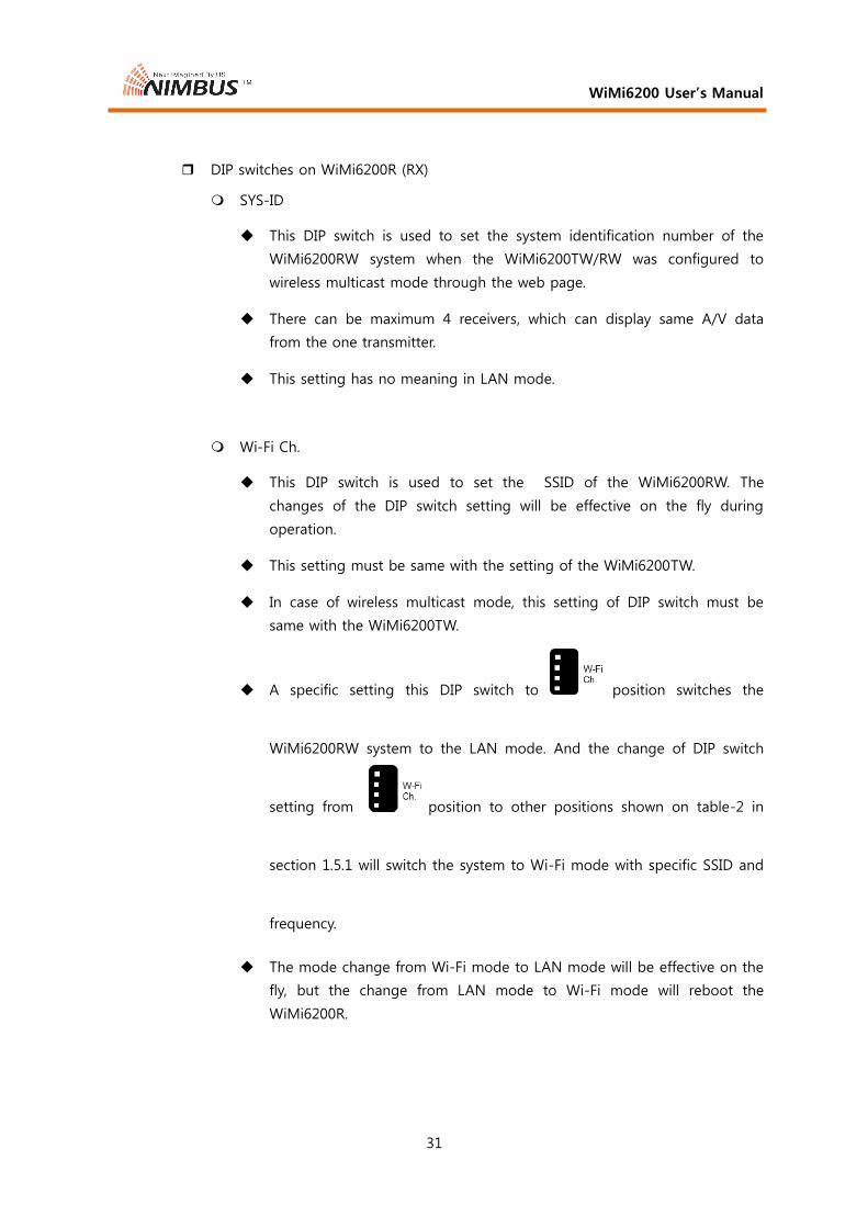
DIP switches on WiMi6200R (RX)
SYS-ID
This DIP switch is used to set the system identification number of the
WiMi6200RW system when the WiMi6200TW/RW was configured to
wireless multicast mode through the web page.
There can be maximum 4 receivers, which can display same A/V data
from the one transmitter.
This setting has no meaning in LAN mode.
Wi-Fi Ch.
This DIP switch is used to set the SSID of the WiMi6200RW. The
changes of the DIP switch setting will be effective on the fly during
operation.
This setting must be same with the setting of the WiMi6200TW.
In case of wireless multicast mode, this setting of DIP switch must be
same with the WiMi6200TW.
A specific setting this DIP switch to position switches the
WiMi6200RW system to the LAN mode. And the change of DIP switch
setting from position to other positions shown on table-2 in
section 1.5.1 will switch the system to Wi-Fi mode with specific SSID and
frequency.
The mode change from Wi-Fi mode to LAN mode will be effective on the
fly, but the change from LAN mode to Wi-Fi mode will reboot the
WiMi6200R.

WiMi6200 User’s Manual
32
3.2 LED Status on the front and rear panel
This LED status applied to both WiMi6200T and WiMi6200R.
LED status of WiMi6200T (TX)
Power LED:
This LED is lighting when the power is on.
HD-SDI LED:
While the system is booting for 40 ~50 seconds, this LED is blinking.
HD-SDI LED is lighting when booting sequence is finished, and valid video signal is detected at the HD-SDI port.
HD-SDI LED will keep blinking when the valid video is not detected at the HD-SDI port after booting.
Link LED:
While the system is booting for 40 ~50 seconds, this LED is blinking.
This LED is lighting after the booting sequence was completed
RJ-45 LED:
When the Ethernet LAN link is up, then green LED will light, and the link is down, then green LED will off.
When the TX is transmitting/receiving data over Ethernet LAN, the yellow LED will blink fast.
LED status of WiMi6200R (RX)
Power LED:
This LED is lighting when the power is on.
HD-SDI LED:
While the system is booting for 40 ~50 seconds, this LED is blinking.
HD-SDI LED is lighting when booting sequence is finished, and valid video signal is output to the HD-SDI port.
HD-SDI LED will keep blinking when the valid video is not detected at the HD-SDI port in the WiMi6200T transmitter.
Link LED:
While the system is booting for 40 ~50 seconds, this LED is blinking.
This LED will keep blinking until valid Wi-Fi link is established after the booting.
This LED is lighting after valid Wi-Fi link is established.
The number of lights indicates the intensity of the received radio signal.

WiMi6200 User’s Manual
33
RJ-45 LED:
When the Ethernet LAN link is up, then green LED will light, and the link is down, then green LED will off.
When the RX is transmitting/receiving data over Ethernet LAN, the yellow LED will blink.
WiMi6200 User’s Manual
34
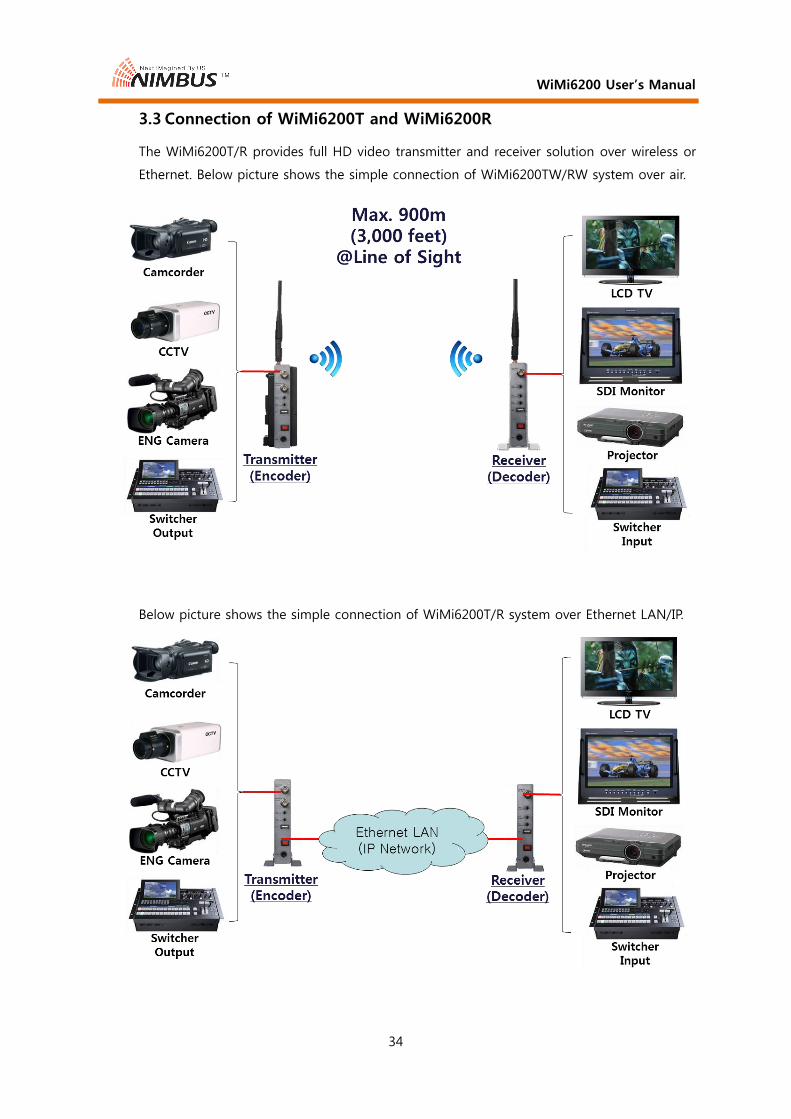
3.3 Connection of WiMi6200T and WiMi6200R
The WiMi6200T/R provides full HD video transmitter and receiver solution over wireless or
Ethernet. Below picture shows the simple connection of WiMi6200TW/RW system over air.
Below picture shows the simple connection of WiMi6200T/R system over Ethernet LAN/IP.

WiMi6200 User’s Manual
35
3.4 Web-based Operation
The WiMi6200T/R can be configured by web-based operation and command line interface
(CLI) via network connection. The CLI can be used for remote configuration of the
WiMi6200T/R through the Telnet/SSH connection. This section shows the detail operation
of web-based configuration. The Internet Explorer or Chrome browser can be used to
access web page of the WiMi6200T/R.
3.4.1 WiMi6200T
R/W means read or write parameter, and R means read only parameter.
3.4.1.1 System Configuration
Below capture shows the web page of System Configuration of Wi-Fi mode.

WiMi6200 User’s Manual
36
Item List R/W Description
1 Ethernet IP R/W
IP address of the encoder. Default & factory setting IP address
of the encoder is 192.168.0.161. The IP address can be changed
to any IP by clicking Submit ○13 button. If the IP address is
changed to other value, then you have to enter changed IP
address on the URL field of the web.
2 Ethernet NetMask R/W Subnet mask of the encoder IP address
3 Ethernet MAC R Mac Address
4 Ethernet Gateway R/W Gateway of Sub-network
5 Streaming Mode R/W
P2P: Point to point mode. Streaming from Ethernet IP○1 to Peer
IP○11
Multicast: Point to multi-point mode, Streaming from one TX to
many RXs with a multicast address○10 .
6 Streaming I/F R Current streaming interface: Wi-Fi or Ethernet LAN
7 Wi-Fi Channel R Current Wi-Fi channel frequency, 36(5180MHz), 44(5220MHz),
149(5745MHz), 157(5785MHz)
8 Wi-Fi SSID R Current SSID of the transmitter
9 Wi-Fi Status R Current Wi-Fi operation status
10 Group IP R/W Multicast IP address
Default multicast IP address is 227.2.2.7.
11 Peer IP R/W IP Address of Decoder. Default & factory setting IP address of
the decoder is 192.168.0.162.
12 Multicast TTL R/W Time to live value of IP when system is running at multicast
mode.
13 Peer Machine R The status of the peer machine, such as P2P or Multicast ,and
its IP address
14 Peer S/W version R The software version of the peer decoder machine, if the peer
machine is a WiMi6200R decoder
15 Local Machine R The status of the local machine, such as P2P or Multicast
16 Local S/W version R The software version of the local machine, WiMi6200T
17 Submit W All the values on this web page will be written to the system
when this button is clicked.
18 Refresh R All the values of the system on this web page will be read from
the system and displayed when this button is clicked.

WiMi6200 User’s Manual
37
Below capture shows the web page of System Configuration of LAN mode. Each
button has same meaning of the Wi-Fi mode.

WiMi6200 User’s Manual
38
3.4.1.2 Serial Port Configuration
Item List R/W Description
1 Baudrate R/W Set baud rate of serial port: 1200 - 115200
2 Stop Bit R/W Stop bit: 1 or 2
3 Character Size R/W Character size: CS5 (5-bit) - CS8 (8-bit)
4 Parity R/W Parity: Odd, Even, Disable
5 Flow Control R Flow Control
6 Submit W All the values on this web page will be written to the system
when this button is clicked.
7 Refresh R All the values of the system on this web page will be read from
the system and displayed when this button is clicked.

WiMi6200 User’s Manual
39
3.4.1.3 S/W Images
① Initial page
Item List R/W Description
1 Image Name R Software (S/W) version that is currently running on the system
2 Created R Created date of working S/W
3 Size R File size of working S/W
4 Image Name R Software (S/W) version that is written in the flash memory
5 Created R Created date of S/W in the flash memory
6 Size R File size of S/W in the flash memory

WiMi6200 User’s Manual
40
7 Downloaded S/W R
Newly downloaded S/W to be written to the flash memory of
the system
Write to Flash: Write downloaded S/W to the flash memory of
the system. New S/W written into the flash memory will be
effective once the system is rebooted by clicking “Reboot
System”
Delete: Remove new downloaded S/W
Caution: Don’t remove the power of the system once the “Write
to Flash” button is clicked. Removing power during the S/W
updating will be the cause of system crash.
8 Server file’s URL URL of the remote server/PC from which new S/W should be
downloaded
9 download W Button to download from remote server/PC
10 Select Local file A firmware update procedure when the S/W is saved in the
local PC
11 Select file W Locate and select S/W file on the local PC
12 No files selected R Shows the file name of selected firmware
13 Upload
Load the selected S/W file on the local PC to the system
memory.
Caution: After clicking “Upload” button, do not click any
browser button and “Refresh” button until the web page is
refreshed automatically
14 Refresh R Refresh this web page.

WiMi6200 User’s Manual
41
② File selection page
Below shows the page after selection of S/W file⑫ on the local PC
using “Select file”⑪.

WiMi6200 User’s Manual
42
③ Downloaded page
Below shows the page after clicking “Upload” button⑬.
Item List R/W Description
15 Delete W Deletes the downloaded S/W from the system RAM memory
16 Write To Flash W
Write the downloaded S/W to the system flash memory. Once
the flash memory is written with the downloaded S/W, then the
WiMi6200T system will be updated with new S/W after the
system is rebooted by web page or recycling the power.
17 Image Name R Software (S/W) version that is downloaded on the system RAM
memory
18 Created R Created date of S/W in the system RAM memory
19 Size R File size of S/W in the system RAM memory
WiMi6200 User’s Manual
43
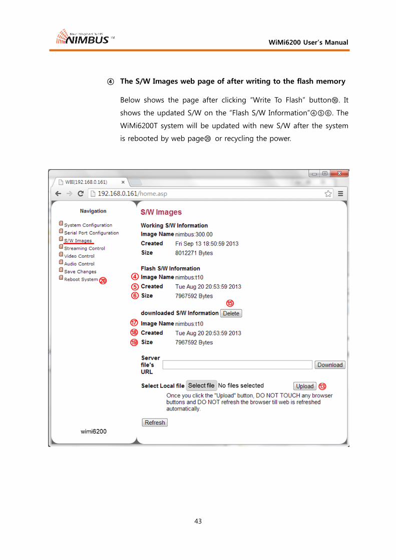
④ The S/W Images web page of after writing to the flash memory
Below shows the page after clicking “Write To Flash” button⑯. It
shows the updated S/W on the “Flash S/W Information”④⑤⑥. The
WiMi6200T system will be updated with new S/W after the system
is rebooted by web page⑳ or recycling the power.

WiMi6200 User’s Manual
44
⑤ The S/W Images web page of after rebooting the system
Below capture shows the web page after rebooting the system. It
shows that the “Working S/W Information”②③ is same with the
“Flash S/W Information”④⑤⑥.

WiMi6200 User’s Manual
45
3.4.1.4 Streaming Control
Item List R/W Description
1 Peer Video Out Port R Video output port information of the decoder
2 Peer Output
Resolution R Video output resolution information of the decoder
3 Video In Port R Current input video port
4 Audio In Port R Current input audio port
5 Video Signal R
Shows the status of input Video Signal. If the video signal is
detected, then the item ⑥⑦⑧ will be displayed. If video is
not connected, the Video Signal will show “not detected” ⑨
only without any displays of ⑥⑦⑧.
6 Resolution (In/Enc) R
Resolution information of the input video signal, if detected.
The first one is the information of the input video signal, and
the latter is the information of the encoded video.
7 Color Space R Color space information of the input video signal, if detected.
5,6,7 Video Signal R If video is not connected, the Video Signal will show “not
detected” only without any displays of ⑥⑦⑧.
8 Streaming R Status about audio, video and streaming server

WiMi6200 User’s Manual
46
9 Restart Streaming W Restarts streaming
10 Forced Enc Res R/W
Selection of forced encoding resolution to be encoded on the
WiMi6200T.
- WiMi6200T supports downscale only, so the resolutions that
is smaller than input resolution will be listed in the drop
box.
- WiMi6200T cannot make more frames than input signal. If
you select a frame rate which is larger than input frame rate,
then WiMi6200T will encode by input frame rate and
WiMi6200R will display to the selected frame rate.
- WiMi6200T cannot convert progressive video to interlaced
video, or vice versa. Only same scanning resolutions are
listed in the drop box.
- Irrespective of this selection, if the selected signal is not
possible to be displayed on current output port of
WiMi6200R, or the monitor on RX side cannot accept it
then, the WiMi6200T will encode the video to another
resolution.
Input means no forced encoding with specific resolution.
11 Encapsulation R/W
Selection of the encapsulation method of RTSP or MPEG-TS for
the streaming server.
RTP: RTP encapsulation mode. This is normal video streaming
mode for WiMi6200R decoding and the RTSP client (software
decoder) such as, VLC player or etc.
TS2UDP: MPEG-TS encapsulation mode. The WiMi6200T will
stream video as the MPEG-TS format with the 48kHz linear
PCM audio. If the TS2UDP is selected, the WiMi6200R can
decode the video from the WiMi6200T.
12 RTSP Server R/W
This button will be displayed when the RTP is selected in the
Encapsulation. Turn RTSP server ON for RTSP streaming
server mode. In the RTSP server mode, the video from
WiMi6200T can be decoded in the WiMi6200R as well as RTSP
client, simultaneously
13 Submit W All the values on this web page will be written to the system
when this button is clicked.
14 Refresh R All the values of the system on this web page will be read
from the system and displayed when this button is clicked.

WiMi6200 User’s Manual
47
3.4.1.5 Video Control
Item List R/W Description
1 Video Streaming R/W Turn on or off video streaming
2 Coding Mode R/W Selection of Encoding Method.
GOP: Frame encoding mode
RandIntraCoded: Slice encoding mode with random refresh
ContIntraCoded: Slice encoding mode with continuous refresh
3 GOP Size R/W GOP Size
4 Intra Count R/W P frame/I frame count of the Intra-frame encoding
5 Forcing I-frame W
In systems where a large GOP is used it may be necessary to
force to generate an I-frame to assist the decoder that needs I-
frame to start decoding
6 Video
Bitrate(Mbps)
R/W Video encoding bit rate that limits the maximum encoding bit
rate with the unit of Mbps. Value “0” of this field means
default encoding rate, 12Mbps. The encoding rate can be set
from 0.1Mbps ~ 30Mbps.
Note: Maximum encoding rate can be set to 40~45Mbps. But
there may be some juddering on this encoding rate.

WiMi6200 User’s Manual
48
7 Frame or Field
Rate
R/W Video frame rate setting ranged from 0 to 30 integer value.
Value “0” means the input frame rate. The reducing frame rate
is useful to reduce the total bandwidth for video transmission.
If the Video Bitrate⑥ is same and the frame is reduced to
half, then actual encoding bit rate would be half of the
specified video encoding rate.
8 Real video
Bitrate(Mbps)
R Actual video encoding rate. When the frame rate is low, such
as 1 or 2, the encoding rate cannot be done as specified in
the Video Bitrate. So, this shows the actual encoding rate.
Below capture shows an example of this case.
9 OSD Status R/W Turn “On Screen Display” on or off. The OSD will show
encoding frame rate, bit rate and QP value for system
debugging. The QP stands for a quantization parameter that
means complexity level of the encoding. Low value shows the
low loss encoding and high value means higher loss encoding
from the original video quality.
10 Submit W All the values on this web page will be written to the system
when this button is clicked.
11 Refresh R All the values of the system on this web page will be read
from the system and displayed when this button is clicked.

WiMi6200 User’s Manual
49
3.4.1.6 Audio Control
Item List R/W Description
1 Audio Streaming R/W Audio streaming method.
Stereo: 2 channels of the stereo audio will be transmitted.
Mono: Left channel of the stereo audio will be transmitted.
2 PCM Compress R/W PCM linear compression method defined by ITU-T G.711
None: no PCM linear compression is applied. 768kbps for one
channel audio, and 1,536kbps for stereo audio.
aLaw: European standard of G.711 compression. 384kbps for
one channel audio, and 768kbps for stereo audio.
uLaw: North American standard of G.711 compression.
384kbps for one channel audio, and 768kbps for stereo audio.
3 PCM 8KHz Down
Sample
R/W Not supported in WiMi6200T/R

WiMi6200 User’s Manual
50
4 Audio Direction R/W Audio destination from the encoder specifies the type of audio
decoder.
RTSP = RTSP client only
RX = WiMi6200R only
ALL = Both RTSP and WiMi6200R
5 InterComm
Audio
R/W Turn On or Off of InterComm audio
6 Submit W All the values on this web page will be written to the system
when this button is clicked.
7 Refresh R All the values of the system on this web page will be read
from the system and displayed when this button is clicked.

WiMi6200 User’s Manual
51
3.4.1.7 Save Changes
Item List R/W Description
1 Save W
Click on “Save” to save ALL changes made and submitted on
individual pages to FLASH. If there is a notification on the top
of the web page like this “System configurations are changed”
in red, then one or more parameters were changed during the
operation. If these changes should be effective at next power
on or reboot, then you have to click “Save” button. It will show
the “Save” button one more time to confirm saving.
Below capture shows the second page of Save Changes. If you
click the Save button② again, all the changes will be saved.

WiMi6200 User’s Manual
52
3.4.1.8 Reboot System
Item List R/W Description
1 Reboot W
Click on “Reboot” will restart the system with all settings which
were modified and saved. It will show the “Reboot” button one
more time to confirm rebooting the system. Below capture
shows the second web page of Reboot System.

WiMi6200 User’s Manual
53
3.4.2 WiMi6200R
R/W means read or write parameter, and R means read only parameter.
3.4.2.1 System Configuration
Below capture shows the web page of System Configuration of Wi-Fi mode.
Item List R/W Description
1 Ethernet IP R/W
IP address of the WiMi6200R decoder. Default & factory setting
IP address of the decoder is 192.168.0.162. The IP address can
be changed to any IP by clicking Submit⑬ button. If the IP
address is changed to other value, then you have to enter new
IP address on the URL field of the web.
2 Ethernet NetMask R/W Subnet mask of the decoder IP address

WiMi6200 User’s Manual
54
3 Ethernet MAC R Mac Address
4 Ethernet Gateway R/W Gateway of Sub-network
5 Streaming Mode R/W
P2P: Point to point mode. Streaming from Ethernet IP○1 to Peer
IP⑧
Multicast: Point to multi-point mode, Streaming from one TX to
many RXs with the multicast address⑦.
6 Streaming I/F R Selection of streaming interface: Ethernet LAN
7 Wi-Fi RXID
(multicast) R
Current receiver ID selected on the front panel of the
WiMi6200R. There can be maximum 4 receivers for one
transmitter when the system is operating in Wi-Fi mode. This
Wi-Fi RXID is used to identify specific RX from the TX. The one
value must be assigned to the only one receiver in one Wi-Fi
network with same SSID.
8 Wi-Fi SSID R Current SSID selected on the front panel of the WIMi6200R.
This value must be same with the SSID of the WiMi6200T.
9 Wi-Fi Quality R Wi-Fi signal strength received at this WiMi6200RW
10 Group IP R/W Multicast IP address used for receiving A/V data from the
WiMi6200T. Default multicast IP address is 227.2.2.7.
11 Peer IP(lan) R/W IP Address of peer encoder. Default & factory setting IP address
of the encoder is 192.168.0.161.
12 Peer Machine R The status of the peer machine, such as P2P or Multicast ,and
its IP address
13 Peer S/W version R The software version of the peer encoder machine
14 Local Machine R The status of the local machine, such as P2P or Multicast
15 Local S/W version R The software version of the local machine, WiMi6200R
16 Submit W All the values on this web page will be written to the system
when this button is clicked.
17 Refresh R All the values of the system on this web page will be read from
the system and displayed when this button is clicked.

WiMi6200 User’s Manual
55
Below capture shows the web page of System Configuration of LAN mode. Each
button has same meaning of the Wi-Fi mode.

WiMi6200 User’s Manual
56
3.4.2.2 Serial Port Configuration
Item List R/W Description
1 Baudrate R/W Set baud rate of serial port: 1200 - 115200
2 Stop Bit R/W Stop bit: 1 or 2
3 Character Size R/W Character size: CS5 (5-bit) - CS8 (8-bit)
4 Parity R/W Parity: Odd, Even, Disable
5 Flow Control R Flow Control
6 Submit W All the values on this web page will be written to the system
when this button is clicked.
7 Refresh R All the values of the system on this web page will be read from
the system and displayed when this button is clicked.

WiMi6200 User’s Manual
57
3.4.2.3 S/W Images
① Initial page
Item List R/W Description
1 Image Name R Software (S/W) version that is currently running on the system
2 Created R Created date of working S/W
3 Size R File size of working S/W
4 Image Name R Software (S/W) version that is written in the flash memory
5 Created R Created date of S/W in the flash memory
6 Size R File size of S/W in the flash memory

WiMi6200 User’s Manual
58
7 Downloaded S/W R
Newly downloaded S/W to be written to the flash memory of
the system
Write to Flash: Write downloaded S/W to the flash memory of
the system. New S/W written into the flash memory will be
effective once the system is rebooted by clicking “Reboot
System”
Delete: Remove new downloaded S/W
Caution: Don’t remove the power of the system once the “Write
to Flash” button is clicked. Removing power during the S/W
updating will be the cause of system crash.
8 Server file’s URL URL of the remote server/PC from which new S/W should be
downloaded
9 download W Button to download from remote server/PC
10 Select Local file A firmware update procedure when the S/W is saved in the
local PC
11 Select file W Locate and select S/W file on the local PC
12 No files selected R Shows the file name of selected firmware
13 Upload
Load the selected S/W file on the local PC to the system
memory.
Caution: After clicking “Upload” button, do not click any
browser button and “Refresh” button until the web page is
refreshed automatically
14 Refresh R Refresh this web page.
② File selection page
③ Downloaded page
④ The S/W Images web page of after writing to the flash memory
⑤ The S/W Images web page of after rebooting the system
All of above ②③④⑤ procedures are same with the WiMi6200T
procedure. Please refer the section 3.4.1.3.

WiMi6200 User’s Manual
59
3.4.2.4 Streaming Control
Item List R/W Description
1
Peer Resolution
(In/Enc) R
When there is a video input on the peer encoder, it will show
the video resolution information. The first one is the
information of the input video signal, and the latter is the
information of the encoded video.
Peer Input R When there is no video input on the peer encoder, it will show
this, “not detected”
2 Video out Port R Shows the video out port
3 Display R Information of the current video output resolution
4 Streaming R Information about output video streaming on the decoder
when the video signal is applied on the peer encoder.
5 Restart Streaming W Restarts streaming on the WiMi6200T encoder
6 InterComm Audio R/W Turn On or Off the InterComm audio

WiMi6200 User’s Manual
60
7 RTSP Relay Server R/W
Turn on or off RTSP Relay Server for the RTSP relay streaming
server mode. In the RTSP Relay Server mode, the received audio
and video data from WiMi6200T will be transparently streamed
out to the RTSP clients that were connected to the WiMi6200R
through the Ethernet or IP. Since RTSP Relay Server of
WiMi6200R is just streaming data from WiMi6200T out, data
format and bit-rate of audio and frame-rate and bit-rate of
video are same with WiMi6200T. Although the relay streaming
server is turned on, the normal decoding on the WiMi6200R
over Ethernet will be performed, simultaneously.
8 RTSP Streaming
Mode R/W
P2P: Point to point mode. In this mode, a stream will be
added/removed whenever a RTSP client connected and
disconnected. The number of RTSP clients can be limited by the
encoding rate of the WiMi4000T/6200T/6400T due to the
limitation of WiMi6200R CPU performance.
Multicast: Point to multi-point mode.. In this mode, there will
be always a stream that all RTSP clients can receive it.
9 RTSP Group IP R/W
Multicast IP address. Default multicast IP address is 227.2.2.7.
This Group IP address must be a unique address, if there are
two or more RTSP Servers of WiMi6200R or multicast mode
WiMi6200Ts on the same network.
There is no need to input this multicast IP address on the RTSP
client program when the RTSP server is running at multicast
environment, because the RTSP client program can fetch this
multicast address from the server automatically. So, the IP
address of the WiMi6200R and the port number should be
input to the URL field of the RTSP client program like below.
rtsp://192.168.0.162:8554/stream
10 RTSP Multicast
TTL R/W
Time to live value of IP when the RTSP relay streaming server is
running on multicast mode⑧.
11 Submit W All the values on this web page will be written to the system
when this button is clicked.
12 Refresh R All the values of the system on this web page will be read from
the system and displayed when this button is clicked.

WiMi6200 User’s Manual
61
3.4.2.5 Save Changes
Item List R/W Description
1 Save W
Click on “Save” to save ALL changes made and submitted on
individual pages to FLASH. If there is a notification on the top
of the web page like this “System configurations are changed”
in red, then one or more parameters were changed during the
operation. If these changes should be effective at next power
on or reboot, then you have to click “Save” button. It will show
the “Save” button one more time to confirm saving.
Below capture shows the second page of Save Changes. If you
click the Save button② again, all the changes will be saved.
WiMi6200 User’s Manual
62
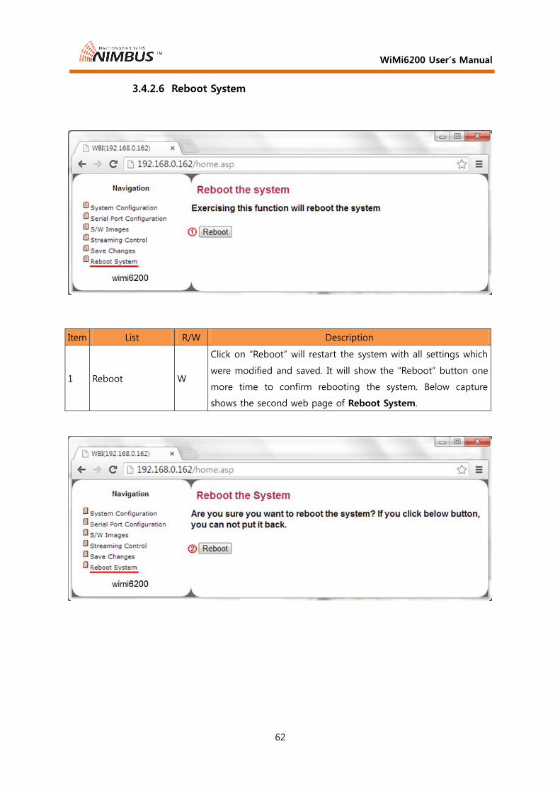
3.4.2.6 Reboot System
Item List R/W Description
1 Reboot W
Click on “Reboot” will restart the system with all settings which
were modified and saved. It will show the “Reboot” button one
more time to confirm rebooting the system. Below capture
shows the second web page of Reboot System.

WiMi6200 User’s Manual
63
3.5 Operation of Multicast for 1:N A/V Transmission
The WiMi4000T/6200T/6400T and WiMi4000R/6200R/6400R can be configured to
receive/decode at multiple decoders to display same video in different places from one
encoder.
IP configuration of the WiMi6200T and WiMi6200R through the web page
Select Multicast on the Streaming Mode in section 3.4.1.1 System Configuration of the WiMi4000T/6200T/6400T. And, click Refresh button, then it will show default multicast IP address. You can change this your own multicast IP address. The multicast IP address must be valid format from 224.0.0.0 to 239.255.255.255. Please refer RFC 5771 for details on multicast address for IPv4.

WiMi6200 User’s Manual
64
② Select Multicast on the Streaming Mode in section 3.4.2.1 System Configuration of the WiMi4000R/6200R/6400R. And, click Refresh button, then it will show default multicast IP address. This multicast IP address must be same with the WiMi4000T/6200T/6400T encoder’s one. If you set the encoder ’s multicast IP address to your own multicast IP address, then you have to change this with the same address.
③ Configure the other WiMi4000R/6200R/6400R with the same process described above ②.
④ Configure the L2 Ethernet switch can support IGMP snooping function.

WiMi6200 User’s Manual
65
IGMP Snooping Function of the L2 Ethernet switch
A switch will, by default, flood multicast traffic to all the ports in a broadcast domain (or the VLAN equivalent). Multicast can cause unnecessary load on host devices by requiring them to process packets they have not solicited. When purposefully exploited this is known as one variation of a denial-of-service attack. IGMP snooping is designed to prevent hosts on a local network from receiving traffic for a multicast group they have not explicitly joined. It provides switches with a mechanism to prune multicast traffic from links that do not contain a multicast listener (an IGMP client).
IGMP snooping allows a switch to only forward multicast traffic to the links that have solicited them. Essentially, IGMP snooping is a layer 2 optimization for the layer 3 IGMP. IGMP snooping takes place internally on switches and is not a protocol feature. Snooping is therefore especially useful for bandwidth-intensive IP multicast applications such as IPTV.
IGMP querier
In order for IGMP, and thus IGMP snooping, to function, a multicast router must exist on the network and generate IGMP queries. The tables created for snooping (holding the member ports for each a multicast group) are associated with the querier. Without a querier the tables are not created and snooping will not work. Furthermore IGMP general queries must be unconditionally forwarded by all switches involved in IGMP snooping. Some IGMP snooping implementations include full querier capability. Others are able to proxy and retransmit queries from the multicast router.
Prerequisites for multicasting A/V over IP network
There must be one or more Multicast routers on the network to transport multicast A/V traffic on the network that the single WiMi4000T/6200T/6400T and multiple WiMi4000R/6200R/6400R are working. And all the L2 Ethernet switches on the network between the WiMi4000T/6200T/6400T and WiMi4000R/6200R/6400R must support IGMP snooping function. If there is a L2 Ethernet switch that does not support IGMP snooping function, then the multicast A/V traffic will be flooded to every ports that can be resulted in blocking the multicast A/V traffic.
Multicasting A/V over single sub-network
There is one simple solution for replacing an expensive multicast router, if the multicasting is transmitted and received in one sub-network. Some of advanced L2 Ethernet switch transmits IGMP query packets through their Ethernet port. If there is no need to multicast IP traffic over the different sub-network, then you can use this cheap L2 Ethernet switch. The one sample of this advanced L2 switch that Nimbus has tested is the HP’s V1910-16G Switch (JE005A).

WiMi6200 User’s Manual
66
3.6 Operation of USB port
The USB port operation is applied to both WiMi6200T and WiMi6200R
IP configuration of the WiMi6200T and WiMi6200R through the USB port
Create both a config.tx and a config.rx files on the root directory of the USB memory stick.
The config.tx file must include below text
FACTORY_DEFAULT=YES : This line must be located at first line of the file.
ipaddr=192.168.0.161 : IP address of the WiMi6200T
netmask=255.255.255.0 : Sub-net Mask of the WiMi6200T
gatewayip=192.168.0.1 : Gateway IP address of the WiMi6200T
PEER_IP=192.168.0.162 : IP address of the peer device (WiMi6200R)
# Comments of the above configurations
The config.rx file must include below text
FACTORY_DEFAULT=YES : This line must be located at first line of the file
ipaddr=192.168.0.162 : IP address of the WiMi6200R
netmask=255.255.255.0 : Sub-net Mask of the WiMi6200R
gatewayip=192.168.0.1 : Gateway IP address of the WiMi6200R
PEER_IP=192.168.0.161 : IP address of the peer device (WiMi6200T)
Insert the USB memory into the USB port of the WiMi6200T, and recycle the power.
Wait for 3~4 seconds until the LED stops the fast blinking, and after stop fast blinking the USB memory must be removed from the WiMi6200T/R.
Note: The USB memory must be removed from the WiMi6200T/R once the fast blinking of LEDs stops.
Note: The character “#” in the beginning of the line will ignore the rest of text on the same line.
Note: If there is only “FACTORY_DEFAULT=YES” in the file, then it will work as the factory reset operation.

WiMi6200 User’s Manual
67
4. Trouble shooting
4.1 Changing IP address of the WiMi6200T or WiMi6200R
A pair of the WiMi6200T and WiMi6200R was set to default IP address, which is
192.168.0.161 for WiMi6200T (TX) and 192.168.0.162 for WiMi6200R (RX). So, if this IP
address is using by other IP device on the same network, then you have to change the IP
address to another one through the web interface of the TX and RX. You can connect to
the embedded web page of the TX/RX with TX/RX’s IP address via Internet Explorer. Please
connect a laptop or PC to the TX (RX) with a CAT.5e Ethernet cable directly. And enter the
below IP address on the URL of Internet Explorer/Chrome.
Changing IP address of the WiMi6200T
1) Input default IP Address, which is 192.168.0.161①.
2) Select System Configuration ②.

WiMi6200 User’s Manual
68
3) Change the IP address with “Ethernet IP”, “Ethernet NetMask” and “Gateway” with proper value③④⑤.
4) Submit button press⑥.
5) If you want to save changed information, then follow the Save Change section, 3.4.1.7.
6) Enter the new IP address of the WiMi6200T on the URL field of the web browser.
Changing IP address of the WiMi6200R
Same changes should be repeated to the WiMi6200R.

WiMi6200 User’s Manual
69
4.2 How to connect PC to WiMi6200T or WiMi6200TW over Wi-Fi
Connect Desk-top or Lap-top PC directly to the WiMi6200TW over Wi-Fi for running VLC player on the PC
WiMi6200TW’s SSID must be visible from Wi-Fi interface of the PC.
Typical SSID of the WiMi6200TW is WiMi6200_xx. Refer Table-2 Selection of Wi-Fi Ch. and SSID on the front panel of the WiMi6200T on section 1.5.1.
Connect to the WiMi6200T with that SSID.
Type a password (Encryption Key) as follow
Security : WPA-PSK
Encryption : TKIP
Encryption Key : xyj<SSID>

WiMi6200 User’s Manual
70
Check the network connection using “ping 192.168.2.1” at PC. (WiMi6200T’s wireless IP address is fixed to 192.168.2.1)
When the PC is connected to the WiMi6200TW, you can run VLC player (ver. 1.0 or later). Enter the following into the URL field.
rtsp://192.168.2.1:8554/stream
Note: The WiMi6200TW supports only 5GHz band of Wi-Fi. So the PC, wireless AP, smart phone or tablet PC must support 5GHz band operation.
Connect Desk-top or Lap-top PC to the WiMi6200T over Wi-Fi via wireless AP for running VLC player on the PC
Connect the WiMi6200T to a wireless access point (AP) through an Ethernet cable.
Connect PC to the wireless AP over 802.11n Wi-Fi (5GHz mode, if possible).
Check the network connection to the IP address of the WiMi6200T using “ping” at the PC.
When the PC is connected to the WiMi6200T, you can run VLC player (ver. 1.0 or later). Enter the following into the URL field.
rtsp://IP address of WiMi6200T:8554/stream
WiMi6200 User’s Manual
71
4.3 How to connect Smart Phone/Tablet PC to WiMi6200TW over Wi-Fi
Connect smart phone or tablet PC directly to WiMi6200TW over Wi-Fi for running BSplayer (Android devices) or VLC player (IOS devices)
Usually, the smart phone or tablet PC can decode SD video (480p60/576/p50) well. But, the full HD (1080p60/50) or 720p60/60 would not be decoded well in some smart phones or tablet PCs. In this case if the resolution of the encoding video is changed to lower resolutions or reduce the frame rate from 60/50 to 30/25, then it will be decoded well.
Be sure, the smart phone or tablet PC must support 5GHz Wi-Fi (IEEE 802.11a/n).
Typical SSID of the WiMi6200TW is WiMi6200_xx. Refer Table-2 Selection of Wi-Fi Ch. and SSID on the front panel of the WiMi6200T on section 1.5.1.
Connect to WiMi6200TW with that SSID.
Type a password (Encryption Key) as follow
Encryption Key: xyj<SSID>.
Ex) If the SSID is WiMi6200_02, then the key value is xyjWiMi6200_02, case
sensitive.
When the mobile device is connected to the WiMi6200TW, you can run the application, VLC Player for Apple’s IOS device and BSplayer for Android device. Enter the following into the URL field.
rtsp://192.168.2.1:8554/stream
Connect Smart Phone or Tablet PC to the WiMi6200T over Wi-Fi via wireless AP for running BSplayer (Android devices) or VLC player (IOS devices)
Connect the WiMi6200T to a wireless access point (AP) through an Ethernet cable.
Connect the mobile device to the wireless AP over 802.11n Wi-Fi (5GHz mode, if possible).
Check the network connection to the IP address of the WiMi6200T using “ping” at the PC.
When the mobile device is connected to the WiMi6200T, you can run BSplayer (Android devices) or VLC player (IOS devices). Enter the following into the URL field.
rtsp://IP address of WiMi6200T:8554/stream