Embed Size (px)
Citation preview

Wire Rope Failure on the Guppy Winch
John Figert March 8, 2016
Metallurgical Engineer, P.E. MAR 17269
https://ntrs.nasa.gov/search.jsp?R=20170007856 2018-06-14T06:14:37+00:00Z

Background
• On January 6, 2016 at El Paso, the Guppy winch motor was changed. After completion of the operational checks, the load bar was being reinstalled on the cargo pallet when the motor control FORWARD relay failed in the energized position. The pallet was pinned at all locations (each pin has a load capacity of 16,000 lbs.) while the winch was running. The wire rope snapped before aircraft power could be removed.
• After disassembly, the fractured wire rope was shipped to ES4 lab for further characterization of the wire rope portion of the failure.
Follow-up on the Winch Malfunction
• The system was being operated without a clear understanding of the system capability and function. The proximate cause was the failure of the K48 –Forward Winch Control Relay in the energized position, which allowed the motor to continuously run without command from the hand controller, and operation of the winch system with both controllers connected to the system. This prevented the emergency stop feature on the hand controller from functioning as designed. An electrical checkout engineering work instruction was completed and identified the failed relay and confirmed the emergency stop only paused the system when the STOP button on both connected hand controllers were depressed simultaneously.
• The winch system incorporates a torque limiting clutch. It is suspected that the clutch did not slip and the motor did not stall or overload the current limiter. Aircraft Engineering is looking at how to change the procedures to provide a checkout of the clutch and set to a slip torque limit appropriate to support operations.

Wire Rope Requirements per NASA-JSC Drawing 4055007
• MIL-DTL-83420• Construction 7 x 19: 7 Stands, 19 Wires per Stand
• Type I: Nonjacketed Wire Rope
• Composition B: AISI 302 or AISI 304 Stainless Steel
• 5/16 inch diameter • Minimum Breaking Strength of 9000 lbs.
• Minimum Breaking Strength of 5400 lbs. After Endurance Testing (130,000 Cycles of Reverse Bending)
• Regular Lay
• Temperature Range: -65 F to 250 F

D/d for Aircraft Wire Rope
D/d > 18 for 7 x 19

Drum Dimensions D/d Calculation
D/d > 18 for 7 x 19
This D/d ratio indicates the original equipment manufacturer (OEM) design of the drum diameter is appropriately sized to minimize premature wire rope fatigue failure due to bending stresses.

Proper Wire Rope / Groove Fit
From: Wire Rope Users Manual, Third Edition, 1993, p. 55.Drawing View of the
Drum Groove & Wire Rope

An Engineer’s Observation• “…if you stand in either doorway of the Guppy on the ground and look up
at the winch cable that will be not in tension during movement of a heavy load, if you use your phone and film the winch cable, you will see just how slack it gets and how much the bungees work to take up the slack when the winch initially starts to push or pull a heavy load.
• It might give some folks an appreciation for how elastic the winch cable becomes on the non-tensioned end whenever a heavy load is initially applied on the tensioned end.
• Also, when we have loaded or unloaded heavy loads, you will see the load stop, and then it rolls a bit, and then stops, and then rolls a bit, and then stops, repeating this gentle pulsing motion. This may be of interest to someone.”
---Stuart Williams, Guppy Aircraft Engineer

Drum--Grooved
Per the Wire Rope Users Manual, Third Edition, p. 45
• “Adequate tension must be maintained on the rope while it is being wound so that the winding proceeds under continuous tension.”
• “The rope must follow the groove…”

Guppy Winch System After Wire Rope Fracture
Sheaves

Wire Rope Before Itis Removed from the Drum
Wire Fractures
Wire Rope Damage

Drum
Heavy Wear in the Drum Groove Where Wire Rope Separation Occurred

DrumHeavy adhesive wear is observed on the side walls of the drum groove where the wire rope fractured.

The Wire Rope Piece that Separated from the Drum
Dog Leg or Kink
Wire Fractures and Separation

The Wire Rope Piece that Separated from the Drum

Wire Rope Next to the Fracture/Separation on the Drum-Side
This is typical of drum crushing where wires are distorted and displaced from their normal position.

Wire Rope Next to the Fracture/Separation on the Drum-Side

Wire Rope Next to the Fracture/Separation on the Drum-Side

Wire Rope Fracture/Separation on the Drum-Side
The drum crushing is localized.

Wire Rope Fracture/Separation on the Drum-Side
Nonmetallic string used for lubrication during the manufacture of the wire rope.
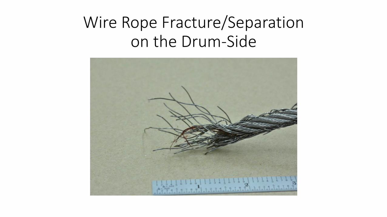
Wire Rope Fracture/Separation on the Drum-Side

Wire Rope Next to the Fracture/Separation on the Dog Leg Side

Wire Rope Fracture/Separation on the Dog Leg Side

Wire Rope Fracture/Separation on the Dog Leg Side
It is roughly 10.8 inches between the sheave and drum!
Dog Leg
From the fracture to the dog leg is a straight line then the wire rope transition to a curve.

Dog Leg

What Does Tensile Overload Look Like?
Necking Tensile Shear
Typical Tensile Break

What does Fatigue look like?

Macroscopic Examination of the Wire Fractures
• 66 Wires Exhibit Necking*
• 18 Wires Exhibit Tensile Shear
• 5 Wires Exhibit Fatigue
• 44 Wires Exhibited Flattening Next to and on the Fracture.*One strand exhibited 19 wires with necking!
• 7 x 19 Wire Rope (133 Wires)• 33% of the Wires exhibited flattening next to the fracture
• 63% of the Wires exhibited overload.
• 4% of the Wires exhibited fatigue.

Scanning Electron Microscopy (SEM)of the Flattened Wires

Scanning Electron Microscopy (SEM)of the Flattened Wires

Scanning Electron Microscopy (SEM)of the Flattened Wires

Scanning Electron Microscopy (SEM)of the Flattened Wires
Evidence of hammering (peening), smearing and adhesive wear is present on the flattened wires.

Wire Rope Section with the Clevis Socket

Wire Rope Section with the Clevis Socket

Wire Rope Section with the Threaded Swageless Fitting

Wire Rope Section with the Threaded Swageless Fitting
DogLeg

Wire Rope Section with the Threaded Swageless Fitting
Dog Leg

Wire Rope Section with the Threaded Swageless Fitting

General Observations
• Both long wire rope sections away from the fracture exhibited minor to low levels of lubrication. The handling of these wire rope sections transferred very little dirt and grime on the nitrile gloves.
• The 74 foot wire rope section with the single tang socket was visually inspected and handled its entire length, no anomalies were detected.
• The 94 foot wire rope section with the threaded swageless fitting was visually inspected and handled its entire length, no anomalies were detected except for one minor kink or dog leg. This may have occurred during the removal process from the Guppy; a cable loop was noted in the same area during the lab unwinding process.

Wire Rope Lubricantshttp://www.machinerylubrication.com/Read/372/wire-rope-lubrication
Wire rope lubricants have two principal functions:• To reduce friction as the individual wires move over each other.
• To provide corrosion protection and lubrication in the core and inside wires and on the exterior surfaces.
There are two types of wire rope lubricants, penetrating and coating. • Penetrating lubricants contain a petroleum solvent that carries the lubricant
into the core of the wire rope then evaporates, leaving behind a heavy lubricating film to protect and lubricate each strand.
• Coating lubricants penetrate slightly, sealing the outside of the cable from moisture and reducing wear and fretting corrosion from contact with external bodies.

Energy Dispersive Spectroscopy (EDS)
WireAISI 304 Standard

Optical Emission Spectroscopy (OES)
• For the Wire Rope sample, the strands were separated, cleaned, and melted into a button before testing by OES. The sample passes for both 302SS and 304SS.
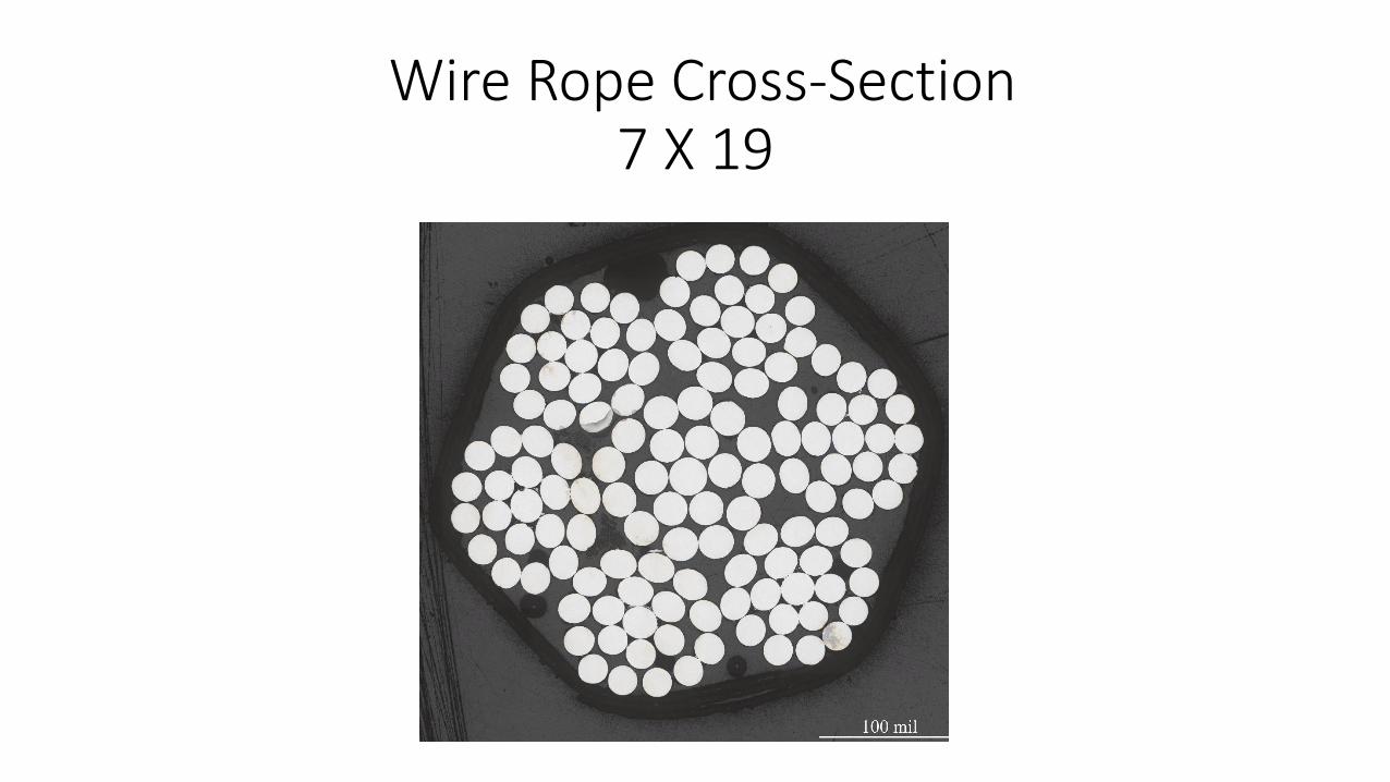
Wire Rope Cross-Section7 X 19

Hardness Testing
Sample: Cable Cross-Section
Material: CRES
Hardness Scale: HV500
Performed by: Frank Samonski
Indent Value
1 493.3
2 491.1
3 500.2
4 500.2
5 460.9
Average 489.1
Std Deviation 16.3
NOTE: 489 HV500 = 48 HRC

Tensile Tests on the Wire Rope RITF Report No. 160048
Wire Rope from the Drum: 8960 lbs.
Wire Rope Away from the Drum: 9270 lbs.
Wire Rope Min. UTS (New): 9000 lbs.
This confirms the macroscopic examination results (page 28) that fatigue at the grooved drum was not a contributing factor in the wire rope failure.

Conclusions
• The wire rope failed from localized drum crushing resulting from very high tensile loads created during the Guppy winch malfunction (the K48 Forward Winch Control Relay in the energized position and operation of the winch system with both controllers connected to the system). Other contributing factors to the drum crushing failure include:• The pallet was pinned at all locations as the winch motor continued to run,• Inadequate tension is maintained in the wire rope system. The wire rope
in the first exit drum groove is exposed to the most slack and peening, the region where the wire rope broke,
• The design of the drum groove was too tight, especially under high tensile loads, and
• The wire rope exhibited almost no lubrication.

Conclusions
• The dog leg or kink near the fracture probably happened during the failure event from the high tensile loads. The location of the dog leg at roughly 10-11 inches from the fracture places the dog leg near the exit sheave and wire rope guide (page 24). Inadequate and/or a release of wire rope tension can produce the strand separation observed at this dog leg (page 25).
• Chemistry, hardness, and inspection of the 7 x 19 wire rope away from the fracture (and adjacent area) indicate no manufacturing process issues with the wire rope.

Recommendations
• Periodic maintenance and inspection should be performed on the Guppy winch system including field lubrication of the wire rope.
• An Ellington Field engineering/design team should make sure that the Guppy winch system has a repeatable method to remove the slack from the wire rope adjacent to the drum & sheaves.
• An Ellington Field engineering/design team should make sure the Guppy Winch loads are light and infrequent. The drum V-groove design, which is not consistent with the recommendations of the Wire Rope Users Manual, maybe acceptable for light loads; however, heavy tensile loads will result in severe pinching of the wire rope and galling of the drum groove, especially with a lubricant-starved, 304 stainless wire rope. Fatigue can be a problem with moderate tensile loads and a properly lubricated wire rope with the V-groove drum design.