Embed Size (px)
Citation preview
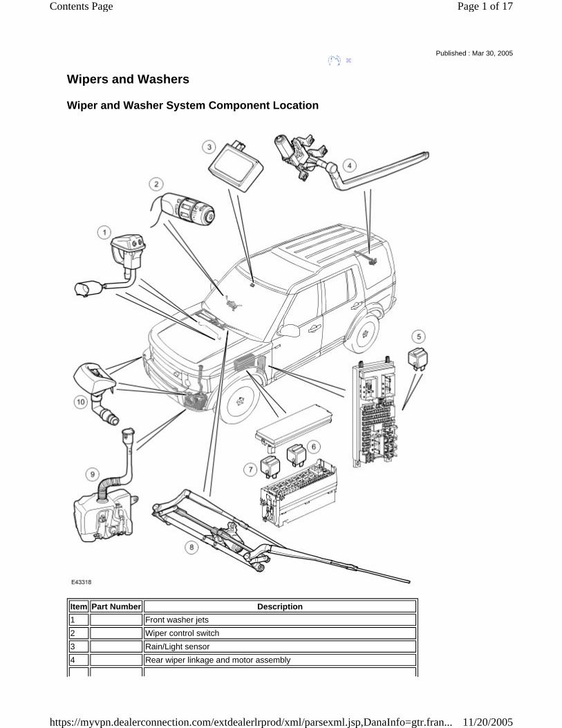
Wipers and Washers
Wiper and Washer System Component Location
Published : Mar 30, 2005
Item Part Number Description 1 Front washer jets2 Wiper control switch3 Rain/Light sensor4 Rear wiper linkage and motor assembly
Page 1 of 17Contents Page
11/20/2005https://myvpn.dealerconnection.com/extdealerlrprod/xml/parsexml.jsp,DanaInfo=gtr.fran...
GENERAL
The wiper and washer system is controlled by the Central Junction Box (CJB) on receipt of requests made by the driver or the rain/light sensor unit (if fitted). All wiper functions for the front and rear wipers are controlled from a multi-function wash/wipe switch assembly located on the right hand side of the steering column. The wiper and washer system comprises:
Front and rear wiper motors A front wiper linkage Two front and one rear wiper arms and blades Two front washer jets and one rear washer jet A washer reservoir and pump A wash/wipe control column switch.
The following optional items can be added to enhance the wiper system:
A rain/light sensor for automatic wiper control Heated front washer jets Headlamp washers Low fluid level sensor (fitted to vehicles with headlamp washers).
The wiper system can be optionally equipped with a rain/light sensor. The sensor, located below the interior rear view mirror, detects rain drops on the windscreen and automatically operates the wipers in the intermittent mode. The column stalk switch must be in the intermittent position for rain/light sensor controlled wiper operation. The front wiper system has five stages of operation and six intermittent delay periods. The five wiper stages are as follows:
Flick wipe Off Intermittent Normal (slow) speed continuous Fast speed continuous
Speed Control Intermittent Mode The intermittent, slow and fast speeds are affected by road speed, providing the speed control intermittent wipe mode has been configured. The intermittent wiper delay periods change with the road speed, with the delay decreasing as the road speed increases. Speed Dependant Wipe Mode When the speed dependant wipe mode has been configured, the normal continuous operation changes to intermittent operation when the vehicle is stationary. The fast speed operation changes to normal operation when the vehicle is stationary. The wiper and washers operate with the ignition switch in positions I or II. Wiper functions are suspended during engine cranking to reduce battery power consumption under high load conditions. Diagnostic information for the wiper system is available and can be retrieved using T4.
5 Rear wiper relay (located in the Central Junction Box (CJB))6 Wiper relay 1 (located in the Battery Junction Box (BJB))7 Wiper relay 2 (located in the BJB)8 Front wiper linkage and motor assembly, including wiper arms and blades9 Washer reservoir and pumps10 Headlamp washer jets
Page 2 of 17Contents Page
11/20/2005https://myvpn.dealerconnection.com/extdealerlrprod/xml/parsexml.jsp,DanaInfo=gtr.fran...
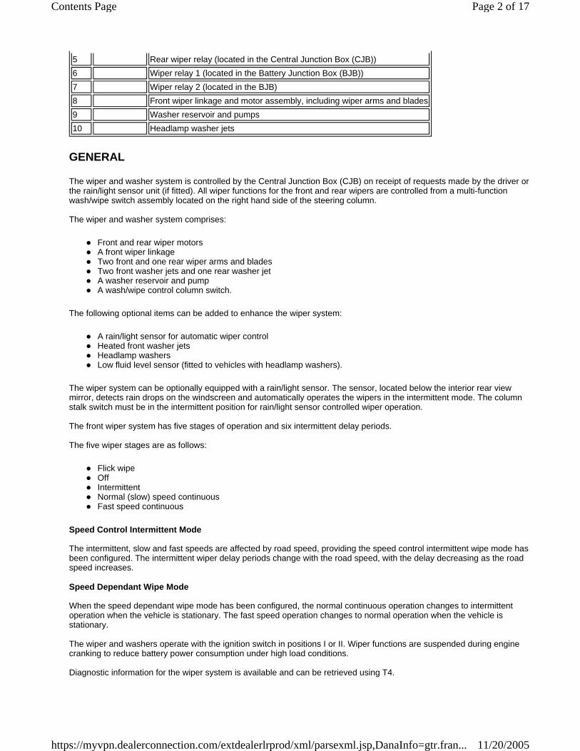
CENTRAL JUNCTION BOX
The CJB is an integrated unit located behind the fascia on the passenger side of the bulkhead. The CJB contains fuses, relays and a number of microprocessors, which control the power supply and functionality of the wash/wipe system and other vehicle systems.
Inputs and Outputs
The CJB receives and sends the following wiper and washer system inputs and outputs:
FRONT WIPER ASSEMBLY
The front wiper assembly comprises:
Wiper motor and linkage assembly Wiper arms and blades Washer reservoir and pumps.
Wiper Linkage
Inputs Outputs Intermittent front wipe switch Front wiper motor (normal) Rear wipe park switch Front wiper motor (fast) Rain/light sensor, if fitted Washer motors Normal (slow) speed continuous switch Heated washer jets (if fitted) Fast speed continuous switch Rear wiper motor relay Flick wipe switch Headlamp power wash motor Front screen wash switch - Rear screen wash switch - Ignition switch - Lighting switch - Low level reservoir status, via CAN - Vehicle speed, via CAN - Front wiper motor park switch - Reverse switch, via CAN - Tail gate open switch - Ambient temperature, via CAN -
Page 3 of 17Contents Page
11/20/2005https://myvpn.dealerconnection.com/extdealerlrprod/xml/parsexml.jsp,DanaInfo=gtr.fran...
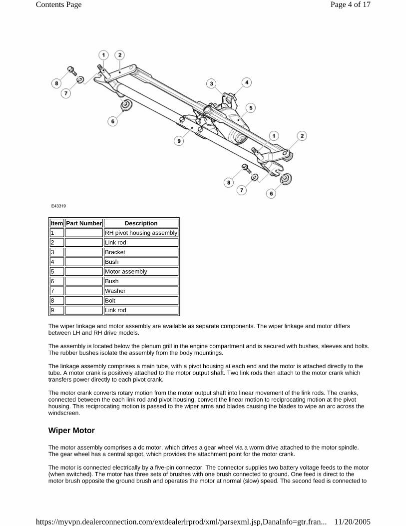
The wiper linkage and motor assembly are available as separate components. The wiper linkage and motor differs between LH and RH drive models. The assembly is located below the plenum grill in the engine compartment and is secured with bushes, sleeves and bolts. The rubber bushes isolate the assembly from the body mountings. The linkage assembly comprises a main tube, with a pivot housing at each end and the motor is attached directly to the tube. A motor crank is positively attached to the motor output shaft. Two link rods then attach to the motor crank which transfers power directly to each pivot crank. The motor crank converts rotary motion from the motor output shaft into linear movement of the link rods. The cranks, connected between the each link rod and pivot housing, convert the linear motion to reciprocating motion at the pivot housing. This reciprocating motion is passed to the wiper arms and blades causing the blades to wipe an arc across the windscreen.
Wiper Motor
The motor assembly comprises a dc motor, which drives a gear wheel via a worm drive attached to the motor spindle. The gear wheel has a central spigot, which provides the attachment point for the motor crank. The motor is connected electrically by a five-pin connector. The connector supplies two battery voltage feeds to the motor (when switched). The motor has three sets of brushes with one brush connected to ground. One feed is direct to the motor brush opposite the ground brush and operates the motor at normal (slow) speed. The second feed is connected to
Item Part Number Description 1 RH pivot housing assembly2 Link rod3 Bracket4 Bush5 Motor assembly6 Bush7 Washer8 Bolt9 Link rod
Page 4 of 17Contents Page
11/20/2005https://myvpn.dealerconnection.com/extdealerlrprod/xml/parsexml.jsp,DanaInfo=gtr.fran...
a motor brush, which is offset from the ground brush and operates the motor at fast speed. With the power supplied through this brush, the current flows through fewer coil windings. This results in a lower resistance to the current flow to the ground brush and gives a higher motor rotational speed. Output control of the wiper motor is through a double contact relay. The relay is located in the Battery Junction Box (BJB). The motor has an internal track switch, which signals the CJB when the wipers have reached the park position. The park signal is closed circuit when the wipers are in the park position. When the wipers are switched off and the CJB receives the park position signal from the motor, the CJB shorts the motor via a relay bridge circuit. This short circuit has the effect of applying a brake to the motor, giving precise positioning of the wiper blades in the park position.
Wiper Arms
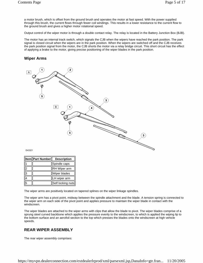
The wiper arms are positively located on tapered splines on the wiper linkage spindles. The wiper arm has a pivot point, midway between the spindle attachment and the blade. A tension spring is connected to the wiper arm on each side of the pivot point and applies pressure to maintain the wiper blade in contact with the windscreen. The wiper blades are attached to the wiper arms with clips that allow the blade to pivot. The wiper blades comprise of a sprung steel curved backbone which applies the pressure evenly to the windscreen, to which is applied the wiping lip to the bottom surface and an aerofoil section to the top which presses the blades onto the windscreen at high vehicle speeds.
REAR WIPER ASSEMBLY
The rear wiper assembly comprises:
Item Part Number Description 1 Spindle caps2 RH Wiper arm3 Wiper blades4 LH wiper arm5 Self locking nuts
Page 5 of 17Contents Page
11/20/2005https://myvpn.dealerconnection.com/extdealerlrprod/xml/parsexml.jsp,DanaInfo=gtr.fran...
Wiper motor Rear washer pump Rear washer jet Wiper arm and blade.
Wiper Motor
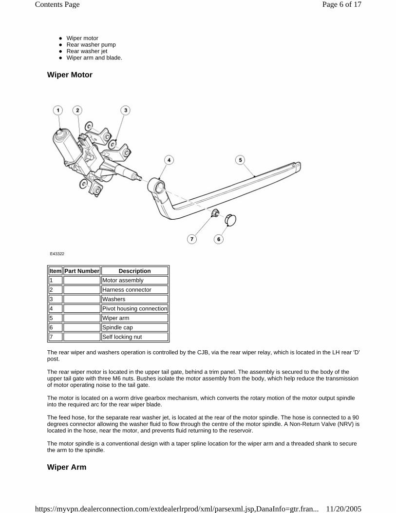
The rear wiper and washers operation is controlled by the CJB, via the rear wiper relay, which is located in the LH rear 'D' post. The rear wiper motor is located in the upper tail gate, behind a trim panel. The assembly is secured to the body of the upper tail gate with three M6 nuts. Bushes isolate the motor assembly from the body, which help reduce the transmission of motor operating noise to the tail gate. The motor is located on a worm drive gearbox mechanism, which converts the rotary motion of the motor output spindle into the required arc for the rear wiper blade. The feed hose, for the separate rear washer jet, is located at the rear of the motor spindle. The hose is connected to a 90 degrees connector allowing the washer fluid to flow through the centre of the motor spindle. A Non-Return Valve (NRV) is located in the hose, near the motor, and prevents fluid returning to the reservoir. The motor spindle is a conventional design with a taper spline location for the wiper arm and a threaded shank to secure the arm to the spindle.
Wiper Arm
Item Part Number Description 1 Motor assembly2 Harness connector3 Washers4 Pivot housing connection5 Wiper arm6 Spindle cap7 Self locking nut
Page 6 of 17Contents Page
11/20/2005https://myvpn.dealerconnection.com/extdealerlrprod/xml/parsexml.jsp,DanaInfo=gtr.fran...
The wiper arm is similar in design to the front wiper arms. The arm attachment hole has tapered splines, which mate with the splines on the wiper spindle. The arm is secured to the wiper motor spindle with a nut. The wiper arm has a pivot point, close to the spindle attachment. A tension spring is connected to the wiper arm on each side of the pivot point and applies pressure to maintain the wiper blade in contact with the windscreen. The wiper blade is attached to the wiper arm with a clip that allows the blade to pivot. The blade comprises a number of levers and yokes to, which the rubber wiper blade is attached. The levers and yokes ensure that the pressure applied by the arm tension spring is distributed evenly along the full length of the blade and also allow the blade to adjust to the curvature and contour of the windscreen. A plastic cap located on the arm pivot point, covers the spindle attachment nut.
WASHER RESERVOIR AND PUMPS
The windscreen washer system comprises: Vehicles without headlamp washers:
A reservoir A washer pump Two washer jets Hoses
Vehicles with headlamp washers:
A reservoir Two washer pumps A level sensor
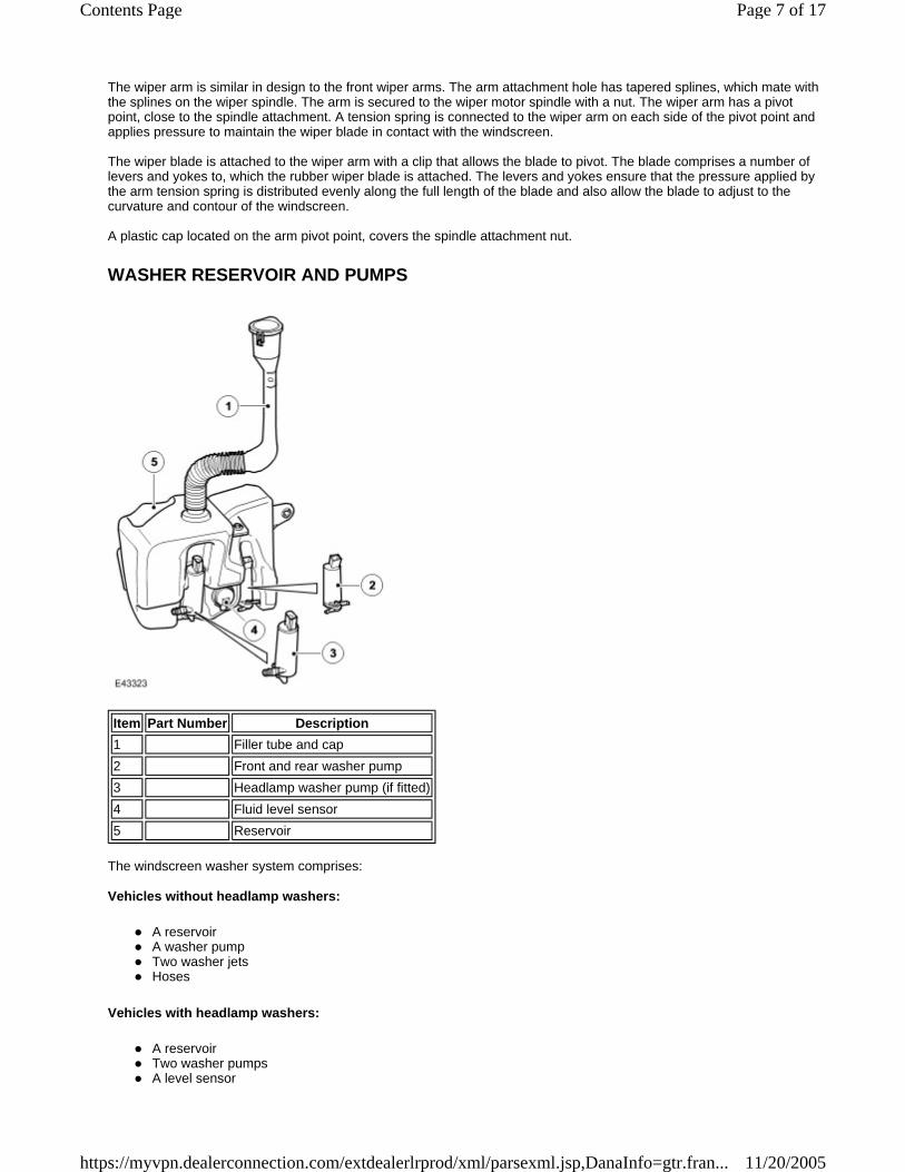
Item Part Number Description 1 Filler tube and cap2 Front and rear washer pump3 Headlamp washer pump (if fitted)4 Fluid level sensor5 Reservoir
Page 7 of 17Contents Page
11/20/2005https://myvpn.dealerconnection.com/extdealerlrprod/xml/parsexml.jsp,DanaInfo=gtr.fran...
Four washer jets - two windshield and two headlamp washers Hoses
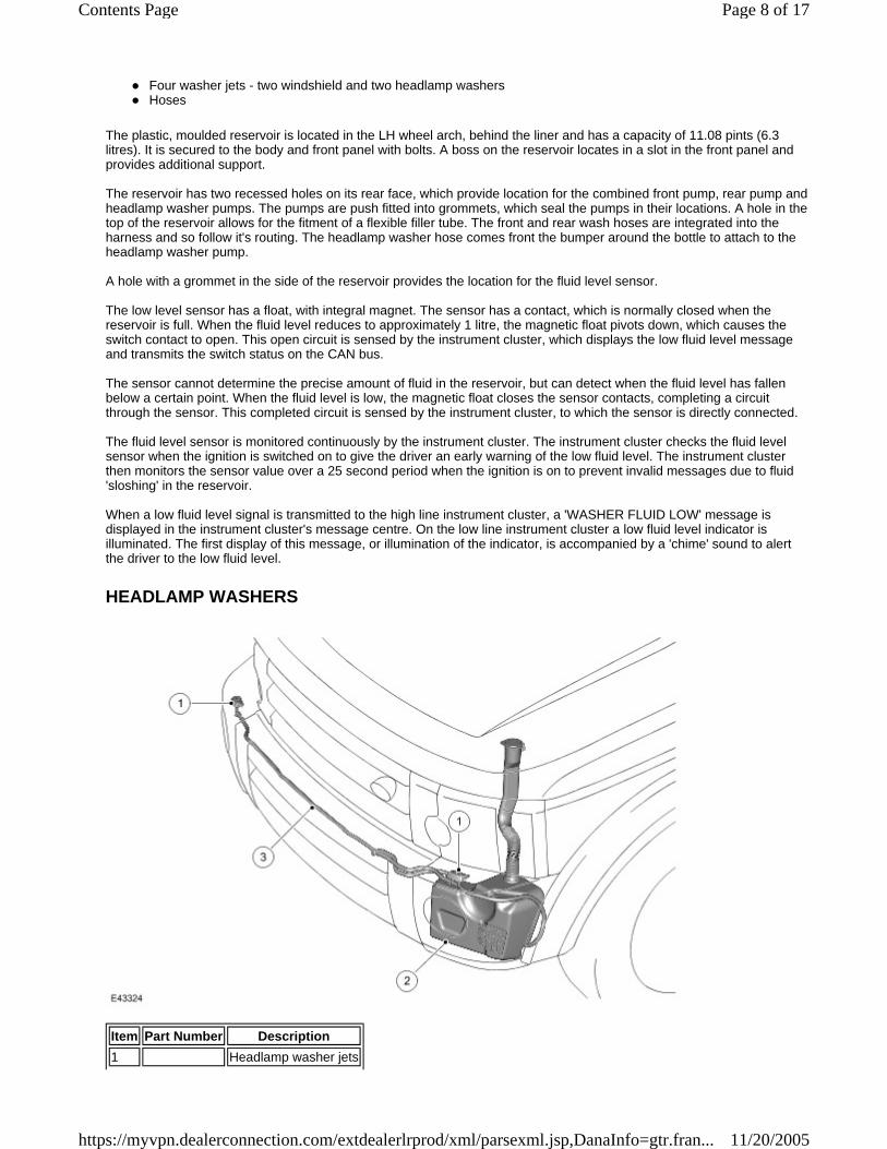
The plastic, moulded reservoir is located in the LH wheel arch, behind the liner and has a capacity of 11.08 pints (6.3 litres). It is secured to the body and front panel with bolts. A boss on the reservoir locates in a slot in the front panel and provides additional support. The reservoir has two recessed holes on its rear face, which provide location for the combined front pump, rear pump and headlamp washer pumps. The pumps are push fitted into grommets, which seal the pumps in their locations. A hole in the top of the reservoir allows for the fitment of a flexible filler tube. The front and rear wash hoses are integrated into the harness and so follow it's routing. The headlamp washer hose comes front the bumper around the bottle to attach to the headlamp washer pump. A hole with a grommet in the side of the reservoir provides the location for the fluid level sensor. The low level sensor has a float, with integral magnet. The sensor has a contact, which is normally closed when the reservoir is full. When the fluid level reduces to approximately 1 litre, the magnetic float pivots down, which causes the switch contact to open. This open circuit is sensed by the instrument cluster, which displays the low fluid level message and transmits the switch status on the CAN bus. The sensor cannot determine the precise amount of fluid in the reservoir, but can detect when the fluid level has fallen below a certain point. When the fluid level is low, the magnetic float closes the sensor contacts, completing a circuit through the sensor. This completed circuit is sensed by the instrument cluster, to which the sensor is directly connected. The fluid level sensor is monitored continuously by the instrument cluster. The instrument cluster checks the fluid level sensor when the ignition is switched on to give the driver an early warning of the low fluid level. The instrument cluster then monitors the sensor value over a 25 second period when the ignition is on to prevent invalid messages due to fluid 'sloshing' in the reservoir. When a low fluid level signal is transmitted to the high line instrument cluster, a 'WASHER FLUID LOW' message is displayed in the instrument cluster's message centre. On the low line instrument cluster a low fluid level indicator is illuminated. The first display of this message, or illumination of the indicator, is accompanied by a 'chime' sound to alert the driver to the low fluid level.
HEADLAMP WASHERS
Item Part Number Description 1 Headlamp washer jets
Page 8 of 17Contents Page
11/20/2005https://myvpn.dealerconnection.com/extdealerlrprod/xml/parsexml.jsp,DanaInfo=gtr.fran...
The headlamp washer assembly is located below each headlamp. The headlamp washer operation is controlled by the CJB via a headlamp washer relay. The relay is located in the Battery Junction Box (BJB).
Head Lamp Wash Only (No Wipe Function)
The headlamp washers are only active when the headlamps and ignition are switched on. If the washer reservoir fluid level becomes low, the instrument cluster sends a message, via the CAN bus, to the CJB, which suspends headlamp wash operation to preserve washer fluid in the reservoir. With the ignition and lights on, headlamp wash is activated on the first operation of the wiper column control switch in the wash/wipe position. The CJB then suspends headlamp wash activation for the next 10 minutes and four operations of the wash/wipe switch. The CJB monitors the operation of the wash/wipe switch and maintains a counter to restrict headlamp washer operation to every fourth operation of the wash/wipe switch in conjunction with a 10 minute timer. The timer prevents a second operation of the headlamp washers within a 10 minute period. Should the washer switch be activated for more than four programmed wipe requests during the 10 minute period, the headlamp washer will remain disabled. Only the next consecutive programmed wipe request, after the 10 timer has expired, will the headlamp washers be enabled. The counter and timer are reset when the ignition is switched off. When headlamp wash is active, the CJB energises the washer pump twice per cycle. The headlamp washer pump is powered for a 0.5 second period.
RAIN/LIGHT SENSOR
2 Reservoir3 Washer fluid tube
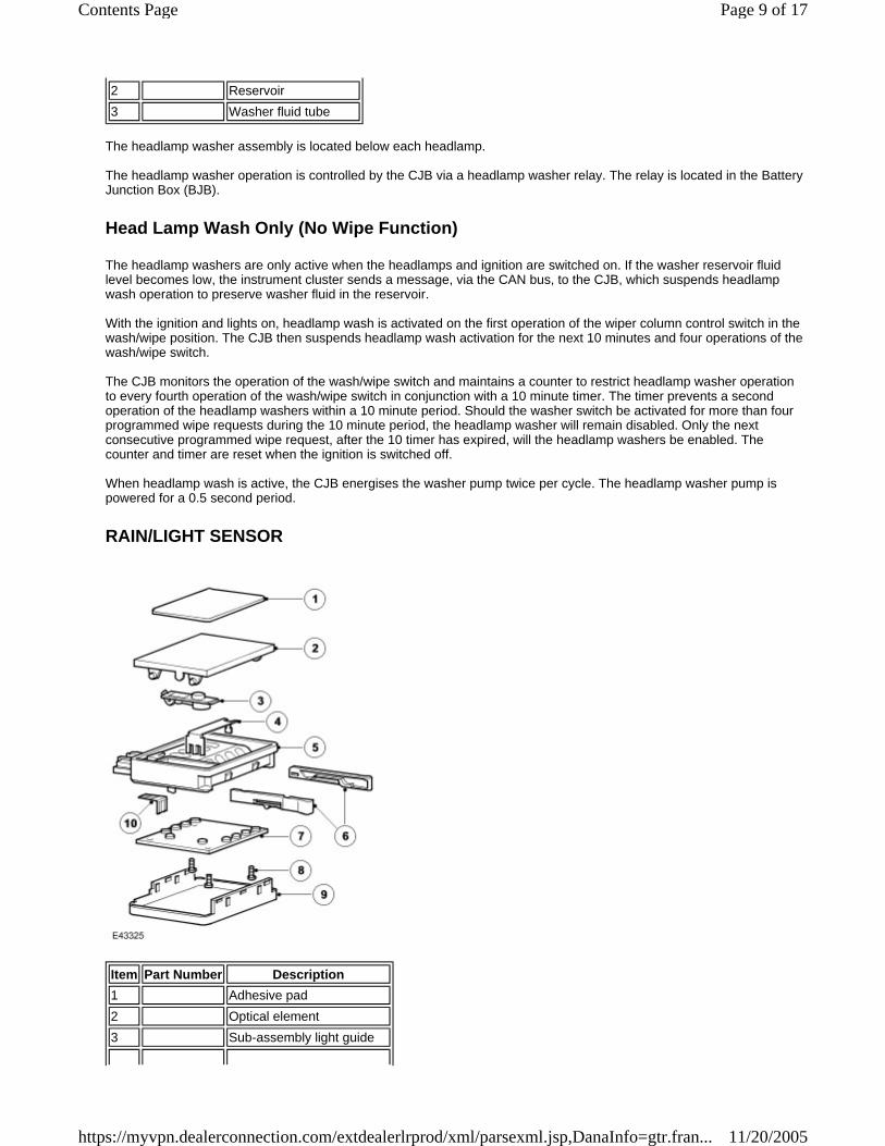
Item Part Number Description 1 Adhesive pad2 Optical element3 Sub-assembly light guide
Page 9 of 17Contents Page
11/20/2005https://myvpn.dealerconnection.com/extdealerlrprod/xml/parsexml.jsp,DanaInfo=gtr.fran...
The rain/light sensor is located at the upper edge of the windscreen, behind the interior rear view mirror. The sensor is mounted on an optical unit, which is heat bonded to the inner surface of the windscreen during manufacture. If damage occurs to the optical unit or the windscreen, then a new windscreen will be required and installation can only be performed by an authorised Land Rover dealer. The rain sensor must be re-initialised to a new windscreen, if fitted, or if transferred to another vehicle, the new rain sensor assembly will automatically re-initialise when powered-up for the first time. In order for this to occur successfully it must be fitted and connected to the optical filaments (bonded to the screen assembly). The rain/light sensor unit attaches to the optical unit via two clips, which latch onto formed tags on the optical unit. Positive retention is achieved by two retaining clips, which force the clips onto the tags. The retaining clips must be withdrawn to facilitate sensor removal. The sensor provides information to the CJB for the optimum wiper operation for the prevailing conditions to maintain the screen in a clear condition at all times. The rain/light sensor is an optical unit, which operates on an infrared waveband. The sensor uses the principle of the laws of reflection on interfacing surfaces between materials with differing refraction properties.
Rain Sensor Functionality
4 Heater5 Housing6 Locking device7 Printed Circuit Board (PCB)8 Screws9 Cover10 Contact pins
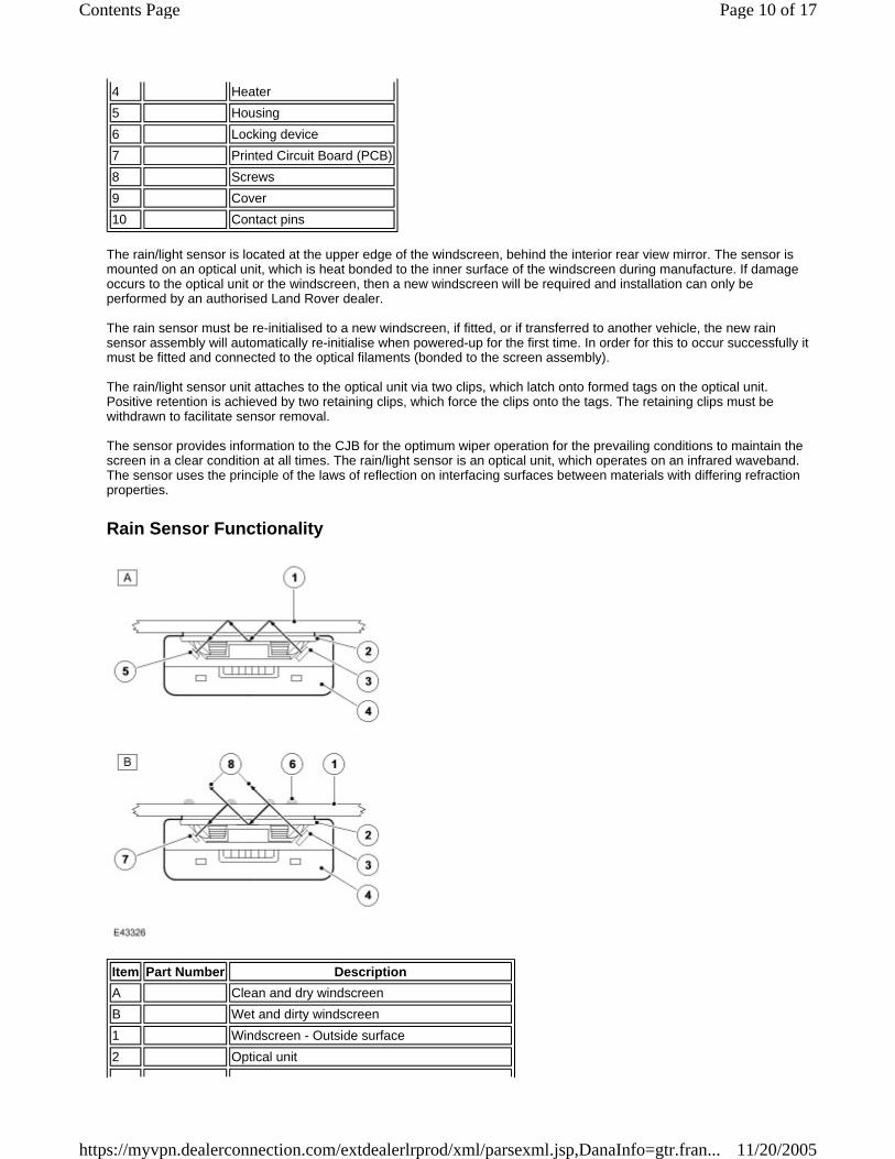
Item Part Number Description A Clean and dry windscreenB Wet and dirty windscreen1 Windscreen - Outside surface2 Optical unit
Page 10 of 17Contents Page
11/20/2005https://myvpn.dealerconnection.com/extdealerlrprod/xml/parsexml.jsp,DanaInfo=gtr.fran...
The rain/light sensor contains transmitter and receiver diodes, which transmit and receive infrared light, which is directed onto the windscreen via an optical unit. The light is directed at an angle so that the light is reflected 100% on the outside surface of the screen and is transmitted back into the optical unit. To receive a 100% reflection, the outer screen surface must be clean and dry. The rain/light sensor is active when the wiper column control switch is in the intermittent position. The rain/light sensor suspends wiper operation when the area of the windscreen for the rain/light sensor is dry and operates the wipers continuously when the windscreen is subject to heavy rainfall. The sensitivity of the rain/light sensor can be adjusted by the driver using the intermittent rotary switch on the wiper stalk. Six sensitivity levels of the sensor can be selected, which has the effect of increasing or decreasing the wiper delay period, allow driver adjustment for the prevailing conditions. When several continuous wipe cycles have taken place, the sensor will maintain the continuous operation to avoid switching back to intermittent from a continuous wipe and back again. The rain/light sensor receives vehicle speed information from the Anti-lock Braking System (ABS) module on the Local Interconnect Network (LIN) bus via the CJB. The sensor increases the sensitivity as the speed increases to optimise wiper operation. When the vehicle speed is reduced to less than 5 mph (8 km/h), the sensitivity is automatically reduced. Below this speed the wipers will only operate continuously in very heavy rain.
Automatic Headlamp Operation
A light sensor is incorporated in the housing of the rain/light sensor to control the operation of the automatic headlamps. The automatic headlamps will function when the lighting control switch is in the 'AUTO' position and the CJB receives a lights on signal from the rain/light sensor. For additional information, refer to Exterior Lighting (417-01 )
WIPER CONTROL COLUMN SWITCH
3 Transmitter diodes (100% light transmitted)4 Rain/Light sensor unit5 Receiver diodes (100% received)6 Water droplets/film7 Receiver diodes (less than 100% light received)8 Lost light
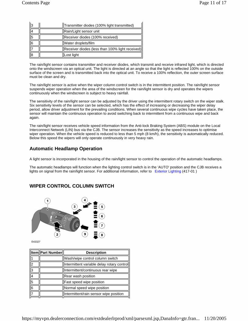
Item Part Number Description 1 Wash/wipe control column switch2 Intermittent variable delay rotary control3 Intermittent/continuous rear wipe4 Rear wash position5 Fast speed wipe position6 Normal speed wipe position7 Intermittent/rain sensor wipe position
Page 11 of 17Contents Page
11/20/2005https://myvpn.dealerconnection.com/extdealerlrprod/xml/parsexml.jsp,DanaInfo=gtr.fran...
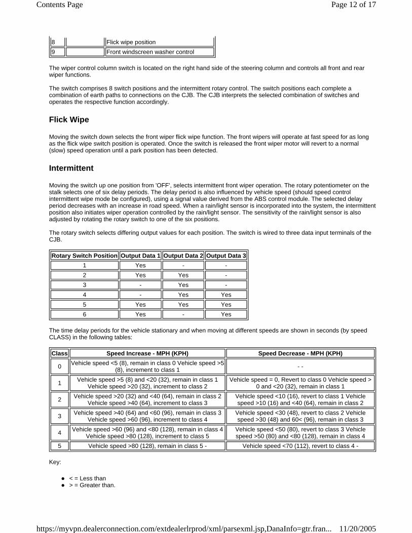
The wiper control column switch is located on the right hand side of the steering column and controls all front and rear wiper functions. The switch comprises 8 switch positions and the intermittent rotary control. The switch positions each complete a combination of earth paths to connections on the CJB. The CJB interprets the selected combination of switches and operates the respective function accordingly.
Flick Wipe
Moving the switch down selects the front wiper flick wipe function. The front wipers will operate at fast speed for as long as the flick wipe switch position is operated. Once the switch is released the front wiper motor will revert to a normal (slow) speed operation until a park position has been detected.
Intermittent
Moving the switch up one position from 'OFF', selects intermittent front wiper operation. The rotary potentiometer on the stalk selects one of six delay periods. The delay period is also influenced by vehicle speed (should speed control intermittent wipe mode be configured), using a signal value derived from the ABS control module. The selected delay period decreases with an increase in road speed. When a rain/light sensor is incorporated into the system, the intermittent position also initiates wiper operation controlled by the rain/light sensor. The sensitivity of the rain/light sensor is also adjusted by rotating the rotary switch to one of the six positions. The rotary switch selects differing output values for each position. The switch is wired to three data input terminals of the CJB.
The time delay periods for the vehicle stationary and when moving at different speeds are shown in seconds (by speed CLASS) in the following tables:
Key:
< = Less than > = Greater than.
8 Flick wipe position 9 Front windscreen washer control
Rotary Switch Position Output Data 1 Output Data 2 Output Data 3 1 Yes - - 2 Yes Yes - 3 - Yes - 4 - Yes Yes 5 Yes Yes Yes 6 Yes - Yes
Class Speed Increase - MPH (KPH) Speed Decrease - MPH (KPH)
0 Vehicle speed <5 (8), remain in class 0 Vehicle speed >5 (8), increment to class 1 - -
1 Vehicle speed >5 (8) and <20 (32), remain in class 1 Vehicle speed >20 (32), increment to class 2
Vehicle speed = 0, Revert to class 0 Vehicle speed > 0 and <20 (32), remain in class 1
2 Vehicle speed >20 (32) and <40 (64), remain in class 2 Vehicle speed >40 (64), increment to class 3
Vehicle speed <10 (16), revert to class 1 Vehicle speed >10 (16) and <40 (64), remain in class 2
3 Vehicle speed >40 (64) and <60 (96), remain in class 3 Vehicle speed >60 (96), increment to class 4
Vehicle speed <30 (48), revert to class 2 Vehicle speed >30 (48) and 60< (96), remain in class 3
4 Vehicle speed >60 (96) and <80 (128), remain in class 4 Vehicle speed >80 (128), increment to class 5
Vehicle speed <50 (80), revert to class 3 Vehicle speed >50 (80) and <80 (128), remain in class 4
5 Vehicle speed >80 (128), remain in class 5 - Vehicle speed <70 (112), revert to class 4 -
Page 12 of 17Contents Page
11/20/2005https://myvpn.dealerconnection.com/extdealerlrprod/xml/parsexml.jsp,DanaInfo=gtr.fran...
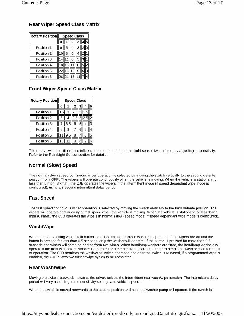
Rear Wiper Speed Class Matrix
Front Wiper Speed Class Matrix
The rotary switch positions also influence the operation of the rain/light sensor (when fitted) by adjusting its sensitivity. Refer to the Rain/Light Sensor section for details.
Normal (Slow) Speed
The normal (slow) speed continuous wiper operation is selected by moving the switch vertically to the second detente position from 'OFF'. The wipers will operate continuously when the vehicle is moving. When the vehicle is stationary, or less than 5 mph (8 km/h), the CJB operates the wipers in the intermittent mode (if speed dependant wipe mode is configured), using a 3 second intermittent delay period.
Fast Speed
The fast speed continuous wiper operation is selected by moving the switch vertically to the third detente position. The wipers will operate continuously at fast speed when the vehicle is moving. When the vehicle is stationary, or less than 5 mph (8 km/h), the CJB operates the wipers in normal (slow) speed mode (if speed dependant wipe mode is configured).
Wash/Wipe
When the non-latching wiper stalk button is pushed the front screen washer is operated. If the wipers are off and the button is pressed for less than 0.5 seconds, only the washer will operate. If the button is pressed for more than 0.5 seconds, the wipers will come on and perform two wipes. When headlamp washers are fitted, the headlamp washers will operate if the front windscreen washer is operated and the headlamps are on – refer to headlamp wash section for detail of operation. The CJB monitors the wash/wipe switch operation and after the switch is released, if a programmed wipe is enabled, the CJB allows two further wipe cycles to be completed.
Rear Wash/wipe
Moving the switch rearwards, towards the driver, selects the intermittent rear wash/wipe function. The intermittent delay period will vary according to the sensitivity settings and vehicle speed. When the switch is moved rearwards to the second position and held, the washer pump will operate. If the switch is
Rotary Position Speed Class 0 1 2 3 4 5
Position 1 6 5 4 3 2 0 Position 2 10 8 6 4 2 1 Position 3 14 11 8 5 3 1 Position 4 18 15 11 8 5 2 Position 5 22 18 13 9 6 3 Position 6 26 21 16 11 7 4
Rotary Position Speed Class 0 1 2 3 4 5
Position 1 3.5 3 2.5 2 1.5 1 Position 2 5 4 3.5 3 2.5 2 Position 3 7 6.5 6 5 4 3 Position 4 9 8 7 6 5 4 Position 5 11 9.5 8 7 6 5 Position 6 13 11 9 8 7 6
Page 13 of 17Contents Page
11/20/2005https://myvpn.dealerconnection.com/extdealerlrprod/xml/parsexml.jsp,DanaInfo=gtr.fran...
operated for more than 10 seconds, the pump will be disabled. When the switch is released, the rear wiper will complete a further two full wipe cycles and then operate on an intermittent function until selected off.
HEATED WINDSCREEN WASHER JETS
Two windscreen washer jets are located in the rear trim panel on the bonnet outer surface. The washer fluid feed hose from the front screen pump is connected to a 'Y' piece connector located between the two jets. Two short lengths of hose connect the jets to the 'Y' piece. Each jet contains a NRV to prevent washer fluid draining back to the reservoir and also to limit the amount of washer fluid, which can be forced by gravity from the jet during cornering. Each washer jet has two ball nozzles, which can rotate in their housing's to obtain the optimum fluid application onto the windscreen. Each washer jet contains a heater element, which prevents the fluid freezing in the nozzles in very cold conditions and a Positive Temperature Coefficient (PTC) sensor, which regulates the temperature. The jet heater elements are controlled by the Automatic Temperature Control Module (ATCM) and a heated washer jet relay in the BJB. For additional information, refer to Control Components (412-04 )
REVERSE GEAR INPUT
The intermittent delay period (below) depends on speed dependant wipe mode being enabled or disabled. The rear wiper also operates if reverse gear is selected and the front wipers are on. If the front wipers are operating continuously when reverse is selected, the rear wiper will also operate continuously as long as reverse gear is engaged. If the front wipers are operating intermittently when reverse is engaged, the rear wiper will complete one wipe cycle then wipe intermittently. On vehicles fitted with rain/light sensor, when reverse gear is selected while the front wipers are in intermittent mode but the rain/light sensor indicates that the front wipers are off, the rear wiper will not operate. If the rain/light sensor subsequently calls for a single wipe, the rear wiper will operate a single wipe cycle. If the rain/light sensor calls for a slow or fast wipe, the rear wiper will operate continuously. The CJB will operate the rear wiper (providing the front wipers are on) upon receipt of a reverse gear signal from the Electronic Automatic Transmission (EAT) module on the CAN bus, via the instrument cluster. On vehicles with manual transmission, the gear position signal is transmitted directly from the transfer box control module and picked by the CJB as an CAN bus message, via the instrument cluster.
'TAIL GATE OPEN' DISABLE
If the rear wiper is switched on or is already running and the tail gate is opened, the rear wiper should not start to run, or should immediately become disabled during a wipe cycle. If the tail gate is subsequently closed, the wiper will resume its normal operation after a delay of three seconds. Should the vehicle speed input be more than 4 mph (6km/h), then the tail gate switch will be deemed as closed. The CJB receives the 'tail gate open' signal directly from the upper tail gate central locking motor.
FRONT AND REAR WIPER MOTOR BLOCKING PROTECTION
The wiper park signal is also used by the CJB for blocking protection of the front wiper motor. This feature protects the motor in the event of the wiper operation being obstructed. If the CJB does not receive a wiper park signal status change for a period of 6 seconds, when the wiper motor is active, the CJB removes the power supply to the motor. The motor will remain disabled until either an alternative motor mode hasbeen selected, or the ignition has been moved to position 0 and back to position I. Should a stall condition be achieved 3 times during a single ignition position I status, then the wiper relay will remain disabled, regardless of wiper switch positions, for 180 seconds. The CJB will not automatically switch the motor on, to prevent the risk of injury. The wiper switch must be moved off and then on to reactivate the wiper motor. The blocking protection is active in all wiper switch positions and can only be reset by turning the ignition off. The rear wiper algorithm contains the same logic as mentioned above.
DIAGNOSTICS
Page 14 of 17Contents Page
11/20/2005https://myvpn.dealerconnection.com/extdealerlrprod/xml/parsexml.jsp,DanaInfo=gtr.fran...
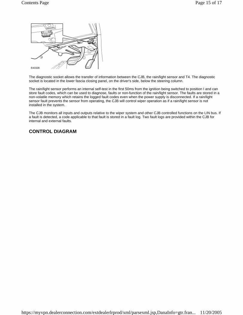
The diagnostic socket allows the transfer of information between the CJB, the rain/light sensor and T4. The diagnostic socket is located in the lower fascia closing panel, on the driver's side, below the steering column. The rain/light sensor performs an internal self-test in the first 50ms from the ignition being switched to position I and can store fault codes, which can be used to diagnose, faults or non-function of the rain/light sensor. The faults are stored in a non-volatile memory which retains the logged fault codes even when the power supply is disconnected. If a rain/light sensor fault prevents the sensor from operating, the CJB will control wiper operation as if a rain/light sensor is not installed in the system. The CJB monitors all inputs and outputs relative to the wiper system and other CJB controlled functions on the LIN bus. If a fault is detected, a code applicable to that fault is stored in a fault log. Two fault logs are provided within the CJB for internal and external faults.
CONTROL DIAGRAM
Page 15 of 17Contents Page
11/20/2005https://myvpn.dealerconnection.com/extdealerlrprod/xml/parsexml.jsp,DanaInfo=gtr.fran...
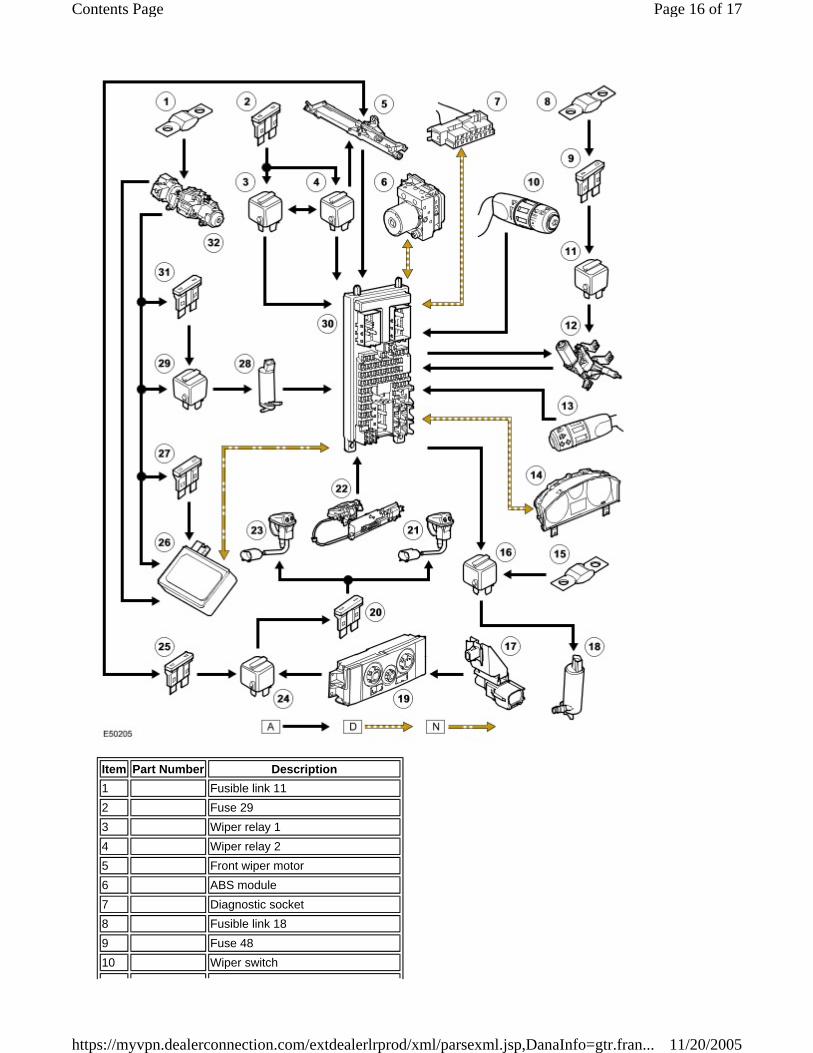
Item Part Number Description 1 Fusible link 112 Fuse 293 Wiper relay 14 Wiper relay 25 Front wiper motor6 ABS module7 Diagnostic socket8 Fusible link 189 Fuse 4810 Wiper switch
Page 16 of 17Contents Page
11/20/2005https://myvpn.dealerconnection.com/extdealerlrprod/xml/parsexml.jsp,DanaInfo=gtr.fran...
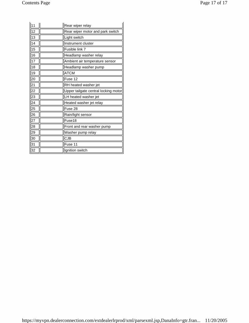
11 Rear wiper relay12 Rear wiper motor and park switch13 Light switch14 Instrument cluster15 Fusible link 716 Headlamp washer relay17 Ambient air temperature sensor18 Headlamp washer pump19 ATCM20 Fuse 1221 RH heated washer jet22 Upper tailgate central locking motor23 LH heated washer jet24 Heated washer jet relay25 Fuse 2826 Rain/light sensor27 Fuse1828 Front and rear washer pump29 Washer pump relay30 CJB31 Fuse 1132 Ignition switch
Page 17 of 17Contents Page
11/20/2005https://myvpn.dealerconnection.com/extdealerlrprod/xml/parsexml.jsp,DanaInfo=gtr.fran...