Embed Size (px)
Citation preview

MAHARASHTRA STATE BOARD OF TECHNICAL EDUCATION
(Autonomous) (ISO/IEC - 27001 - 2005 Certified)
_____________________________________________________________________________________________
Page 1 of 27
WINTER – 14 EXAMINATIONS Subject Code: 12308 Model Answer Page No: ____/ N Important Instructions to examiners:
1) The answers should be examined by key words and not as word-to-word as given in the model answer scheme. 2) The model answer and the answer written by candidate may vary but the examiner may try to assess the understanding level of the candidate. 3) The language errors such as grammatical, spelling errors should not be given more importance. (Not applicable for subject English and Communication Skills) 4) While assessing figures, examiner may give credit for principal components indicated in the figure. The figures drawn by candidate and model answer may vary. The examiner may give credit for any equivalent figure drawn. 5) Credits may be given step wise for numerical problems. In some cases, the assumed constant values may vary and there may be some difference in the candidate’s answers and model answer. 6) In case of some questions credit may be given by judgment on part of examiner of relevant answer based on candidate’s understanding. 7) For programming language papers, credit may be given to any other program based on
equivalent concept.

MAHARASHTRA STATE BOARD OF TECHNICAL EDUCATION
(Autonomous) (ISO/IEC - 27001 - 2005 Certified)
_____________________________________________________________________________________________
Page 2 of 27
Q. NO.
MODEL ANSWER
MARKS TOTAL MARKS
1. (A) Attempt any THREE: 12
(a)
Advantages of power hack sawing: • A major advantage is the relatively low capital investment required. • Easy to set up and simple to operate. • Unskilled or semi-skilled help can be used and one operator can often
attend two or more machines. • Tooling costs are low and the blades are inexpensive enough to make it
economically feasible to throw them away when they become worn. • Tendency for the blades to twist or deflect is minimal. • Maintenance costs are low because of the simple design and operation. • Versatility is another important advantage. The machines can handle most
cutting requirements including practically all materials, a wide range of stock sizes within their capacities and any cut-off length.
• Accuracies maintained and finishes produced range from fair to good depending on the material being sawed.
Disadvantages of power hack sawing: • A major disadvantage is that the machine is slow. • The cutting action is non continuous, and only half of each reciprocating
stroke is productive. • The reciprocating action of hack sawing prohibits the use of blade supports
close to the area of cutting. This may cause bowing of the blade and some inaccuracy. Therefore blades are made thicker, thus requiring more power and producing more chips.
2m (diagm.)
1m (any 1 adv.)
1m (any 1
disadv.)
4m
Foot/
Emergency
switch Coolent feed
Handle/
Thread
Blade Vice On/Off Arm

MAHARASHTRA STATE BOARD OF TECHNICAL EDUCATION
(Autonomous) (ISO/IEC - 27001 - 2005 Certified)
_____________________________________________________________________________________________
Page 3 of 27
• Power hack sawing is essentially a roughing operation and at least 0.05mm should be left on cut surfaces for finishing.
• Blade wear is uneven because only part of the blade is used for cutting since the arm holding the blade obstructs the use of blade ends.
• The necessity for stopping and reversing the direction of blade travel at the end of each stroke causes the cutting speed to vary, thus reducing efficiency.
(b)
Welded angle frames are widely used as a means of stiffening and supporting rectangular ducts for high velocity systems. They also serve as a joining media when assembling sections together by bolting as shown in the figures above.
2m (diagm.)
2m
4m
(c) Versatility i.e. able to adapt or be adapted to many different functions or activities for HSFG bolts include: • On road bridges, structural repairs and extensions, heavy installations
subject to vibrations, power station works, etc. • For shop assembly and on-site assembly of structural steel members
respectively where welding is still more economical but still certain connections are better when bolted. Also difficulties of on-site welding are eliminated with use of HSFG bolts.
• System-built factories and offices are particularly suitable for HSFG bolts. • The performance of preloaded HSFG bolts under fatigue loading is good
because the prestressed bolts are subjected to reduced stress range during each loading cycle when compared with unloaded bolts.
• For structures adjacent to machinery which generate substantial vibration, preloading bolts can help to avoid the loosening of bolts.
• HSFG bolts are used in connections where any slight slip movement would render the integrity of the whole structures break down.
• Owing to its high tensile strength, it is commonly used in connections which require the taking up of high flexure and the tensile stress generated could be readily resisted by it high tensile strength.
4m (any 4)
4m
(d) Pre-forming of ends is the operation stage of curving the ends prior to rolling of the plates and/or sheet metals. Pinch rolls (sheet metal) are designed to
2m
4m

MAHARASHTRA STATE BOARD OF TECHNICAL EDUCATION
(Autonomous) (ISO/IEC - 27001 - 2005 Certified)
_____________________________________________________________________________________________
Page 4 of 27
eliminate these flats at the start of the rolling operation, but other methods have to be employed when pyramid rolls (thick plates) are used. It is important to obtain a true cylinder without flats when the opposite edges touch after the rolling is over.
2m
(e) Equipments used for flame cutting are: • Oxygen and acetylene cylinders • Automatic pressure regulators • Pressure gauge • Cutting torch • Cutting nozzle • Gas hoses • Hose clips • Hose couplers • Gas lighters,
• etc.
4m (any 4)
4m
(B) Attempt any ONE: 06
(a)
Function of the ‘fly’: When the press is operated by a sharp partial revolution of the arm by pulling the handle the ram moves. As the ram moves downwards, the kinetic energy stored up in the two heavy balls (or the fly) mounted on the arm is used up to overcome the resistance of the sheet metal job against deformation.
3m (diagm.)
3m
6m
(b) A typical composite material is a system of materials composing of two or more materials (mixed and bonded) on a macroscopic scale. When designed properly, the new combined material exhibits better strength than would each individual material. Suitability of composites: Different materials are suitable for different
1m
6m

MAHARASHTRA STATE BOARD OF TECHNICAL EDUCATION
(Autonomous) (ISO/IEC - 27001 - 2005 Certified)
_____________________________________________________________________________________________
Page 5 of 27
applications. When composites are selected over traditional materials such as metal alloys or woods, it is usually because of one or more of the following advantages:
Cost: o Prototypes o Mass production o Part consolidation o Maintenance o Long term durability o Production time o Maturity of technology
Weight: o Light weight o Weight distribution
Strength and stiffness: o High strength to weight ratio o Directional strength and/or stiffness
Dimension: o Large parts o Special geometry
Surface properties: o Corrosion resistance o Weather resistance o Tailored surface finish
Thermal properties: o Low thermal conductivity o Low coefficient of thermal expansion
Electric property: o High dielectric strength o Non-magnetic o Radar transparency
5m (any 5)
2. Attempt any TWO: 16 (a) Large circle cutting attachment:
This also is a pivot mounted on a radius bar with the bar attached to the torch head as shown in the figure below. The radius can be adjusted by loosening the wing nut on the centre point/pivot and be moved towards or away from the flame torch to get a wide variation in radius adjustments as shown;
4m
8m

MAHARASHTRA STATE BOARD OF TECHNICAL EDUCATION
(Autonomous) (ISO/IEC - 27001 - 2005 Certified)
_____________________________________________________________________________________________
Page 6 of 27
4m
(b) Bend allowances for sheet metal: When sheet metals are bent through angles of 90⁰ the material on the outside surfaces becomes stretched, whilst that on the inside surfaces of the bends is compressed. It is therefore necessary to make an allowance for these effects when developing a template or when marking out a blank sheet for bending. Thus, bend allowance implies determining the length of the neutral line in the portion of the bend instead of the inside or outside dimensions of the bent metal. The neutral line is an imaginary curve somewhere inside the metal in the bend. Its position does not alter from the original flat length during bending. For the purpose of calculating the allowance for a bend in sheet metal the neutral line curve is regarded as an arc of a circle whose radius is equal to the sum of inside bend radius and the distance of the neutral line in from the inside of the bend. Arc lengths are dependent upon their sector angles and can be determined by calculations as follows: Consider an arc of radius, r+x = 100mm whose subtended angle is θ=90°.
2m
2m
2m
8m

MAHARASHTRA STATE BOARD OF TECHNICAL EDUCATION
(Autonomous) (ISO/IEC - 27001 - 2005 Certified)
_____________________________________________________________________________________________
Page 7 of 27
Then its length will be; 90/360 × 2π(r+x) Alternatively, by inspection the ratio 2π /360 is a constant which may be used for all bend allowance calculations i.e. 2 π/360 =2 ×3.142 /360 =0.0175 Thus the length of the arc will be : 0.0175 ×(r+x) ×θ =0.0175 ×100 ×90° =157.5mm From the above it will be seen that a formula is derived for calculating bend allowances as follows; BEND ALLOWANCE = 0.0175 ×INSIDE RADIUS TO THE NEUTRAL LINE
×SUBTENDED ANGLE OF THE BEND
2m
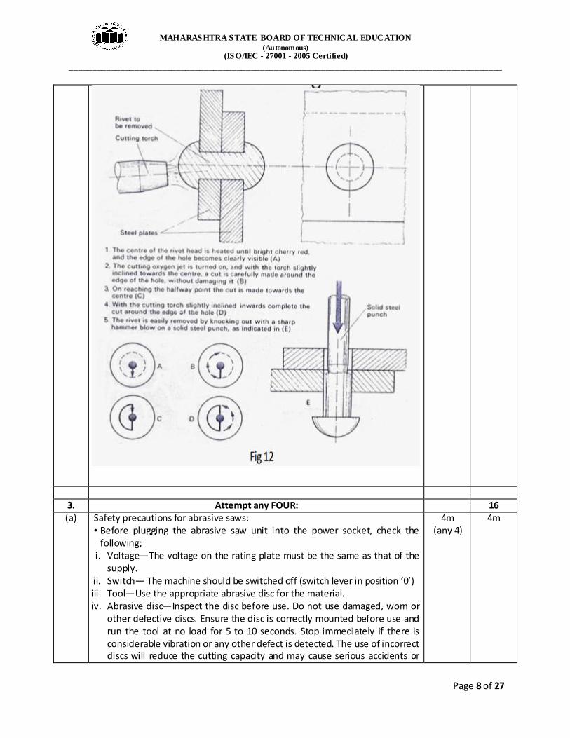
(c) Procedure for defective rivet removal involves stage wise operation that requires the rivet to be heated in a particular pattern at the correct temperature as shown in the diagram below:
8m 8m
MAHARASHTRA STATE BOARD OF TECHNICAL EDUCATION
(Autonomous) (ISO/IEC - 27001 - 2005 Certified)
_____________________________________________________________________________________________
Page 8 of 27
3. Attempt any FOUR: 16 (a) Safety precautions for abrasive saws:
• Before plugging the abrasive saw unit into the power socket, check the following;
i. Voltage—The voltage on the rating plate must be the same as that of the supply.
ii. Switch— The machine should be switched off (switch lever in position ‘0’) iii. Tool—Use the appropriate abrasive disc for the material. iv. Abrasive disc—Inspect the disc before use. Do not use damaged, worn or
other defective discs. Ensure the disc is correctly mounted before use and run the tool at no load for 5 to 10 seconds. Stop immediately if there is considerable vibration or any other defect is detected. The use of incorrect discs will reduce the cutting capacity and may cause serious accidents or
4m (any 4)
4m
MAHARASHTRA STATE BOARD OF TECHNICAL EDUCATION
(Autonomous) (ISO/IEC - 27001 - 2005 Certified)
_____________________________________________________________________________________________
Page 9 of 27
damage to the machine.
• Additional safety precautions for the abrasive saw: i. Always clamp the work firmly. ii. Raise the disc from the cut before releasing the trigger switch. iii. Allow motor to reach full speed before cutting. iv. Verify that the electric power outlet socket has a ground connection and
that it is protected by a fuse and by a residual current circuit breaker. v. Check that guard operates correctly before plugging in the unit. Never
operate the machine without the guard in place. vi. Keep the power cord away from the cutter blade at all times to avoid
damage and the risk of electric shock. vii. If the abrasive saw is powered with compressed air, the user should make
sure that the pressure does not exceed the manufacturer’s recommendation. Higher pressure can create holes in hoses or force the abrasive saw to rotate at an unsafe speed.
viii. If the abrasive saw is gasoline powered, it should be used in a well -ventilated area so that the operator does not inhale gasoline fumes.
ix. As the abrasive disc wears, it could send its grit into the air. The material being cut could also be sent into the air and damage eyes and lungs. The user should always make sure therefore to wear eye shields and a respirator.
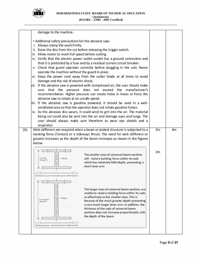
(b) Web stiffeners are required when a beam or plated structure is subjected to a twisting force (Torsion) or a sideways thrust. The need for web stiffeners or gussets increases as the depth of the beam increases as shown in the figures below.
2m
2m
4m

MAHARASHTRA STATE BOARD OF TECHNICAL EDUCATION
(Autonomous) (ISO/IEC - 27001 - 2005 Certified)
_____________________________________________________________________________________________
Page 10 of 27
(c)
Roll-up type in which the machines have adjustment in a vertical direction on the top or bottom pinch roll and in an upward direction on the back roller. This type will roll any size of curvature above the size of the top roll. Roll-down type in which the machines have adjustment in a vertical direction on top or bottom pinch roll and in a downward direction on the back roller. This type will not roll more curvature than will pass beneath the pedestal frame of the machine.
2m (for 2
diagm.)
1m
1m
4m
(d) Blanking: It is the operation of cutting of flat sheet to the desired shape. The metal punched out is the required product and the plate with the hole left on the die goes as waste. The die governs the size of the blank produced and clearance is left on the punch. Piercing: It is the operation of production of a hole in a sheet metal by the punch and die. The material punched out to form the hole constitutes the waste. The punch governs the size of the hole (punch point diameter is less than or equal to material thickness) and clearance is provided on die.
2m
2m
4m
(e) Mechanisation of riveting: Large parts are mainly riveted with pneumatic hand hammers and to a lesser extent with electric hammers. As seen from the figure below, when trigger (10) is depressed with the finger, it acts through lever (12) on the plunger (13) which admits compressed air into valve (14). As this takes place, the piston shoots down and heads the rivet and the distribution valve opens a port for letting the air into the lower chamber of the cylinder, under the piston, making it move upwards. Spring (9) serves for damping the piston’s back blow and thus protects the operator from harmful effect of vibrations and spring (3) prevents the die from falling out. In operation, the pneumatic hammer is held by the handle with the right hand and the trigger is depressed with the forefinger. The left hand grips the
2m
4m

MAHARASHTRA STATE BOARD OF TECHNICAL EDUCATION
(Autonomous) (ISO/IEC - 27001 - 2005 Certified)
_____________________________________________________________________________________________
Page 11 of 27
tool by the barrel or the die to keep the latter on the rivet head. Riveting with a pneumatic hammer is done by two workers; the riveter operates the hammer and the holder-on holds the dolly bar.
2m (diagm.)
(f) Technique of cutting a round bar --- When a round bar is to be flame cut, it is advisable to make a nick with a cold chisel at the point where the cut is to start. This enables the flame cutting to be started more easily. Once the cut is started, the cutting torch should be moved steadily and at a uniform speed, with the small cone of the pre-heating flame just clear off the work surface. There must be no vibration of the cutting head as such movements will result in a ragged cut and in some cases, the cut being halted.
4m 4m
4. (A) Attempt any THREE: 12
(a) Sawing is one of the important cutting operations chiefly concerned with cutting bar stock to a convenient length or size for machining. In sawing, the individual teeth of the saw “track” through the work, each
4m 4m

MAHARASHTRA STATE BOARD OF TECHNICAL EDUCATION
(Autonomous) (ISO/IEC - 27001 - 2005 Certified)
_____________________________________________________________________________________________
Page 12 of 27
tooth deepening the cut made by the preceding tooth in the direction of feed. Either the saw or the work may be fed and by controlling the direction of feed, either straight or curved cut can be produced. The width of the cut is approximately equal to the width of the saw itself.
(b) The basic principle of stiffening can be illustrated by supporting a tumbler of water on a piece of note paper bridging two other tumblers as shown in the figures below.
a) Note paper collapses due to lack b) Corrugating the paper
increases its rigidity of rigidity and it supports the load
c) Principle --- The corrugated shape provides a greater distance between the neutral axis and the areas of compression (top of paper) and tension (bottom of paper) thus enabling the thin note paper to support the applied load
(c) Applied stiffeners for large panel works: The figures below shows methods of stiffening large panels;
Tumbler of
water
Note paper
Empty
tumblers
Original
piece of note
paper
corrugated by
folding
Thickness of
paper
Thickness of
paper
Neutral axis
Neutral axis
Hjghly
stressed area
Highly
stressed area
MAHARASHTRA STATE BOARD OF TECHNICAL EDUCATION
(Autonomous) (ISO/IEC - 27001 - 2005 Certified)
_____________________________________________________________________________________________
Page 13 of 27
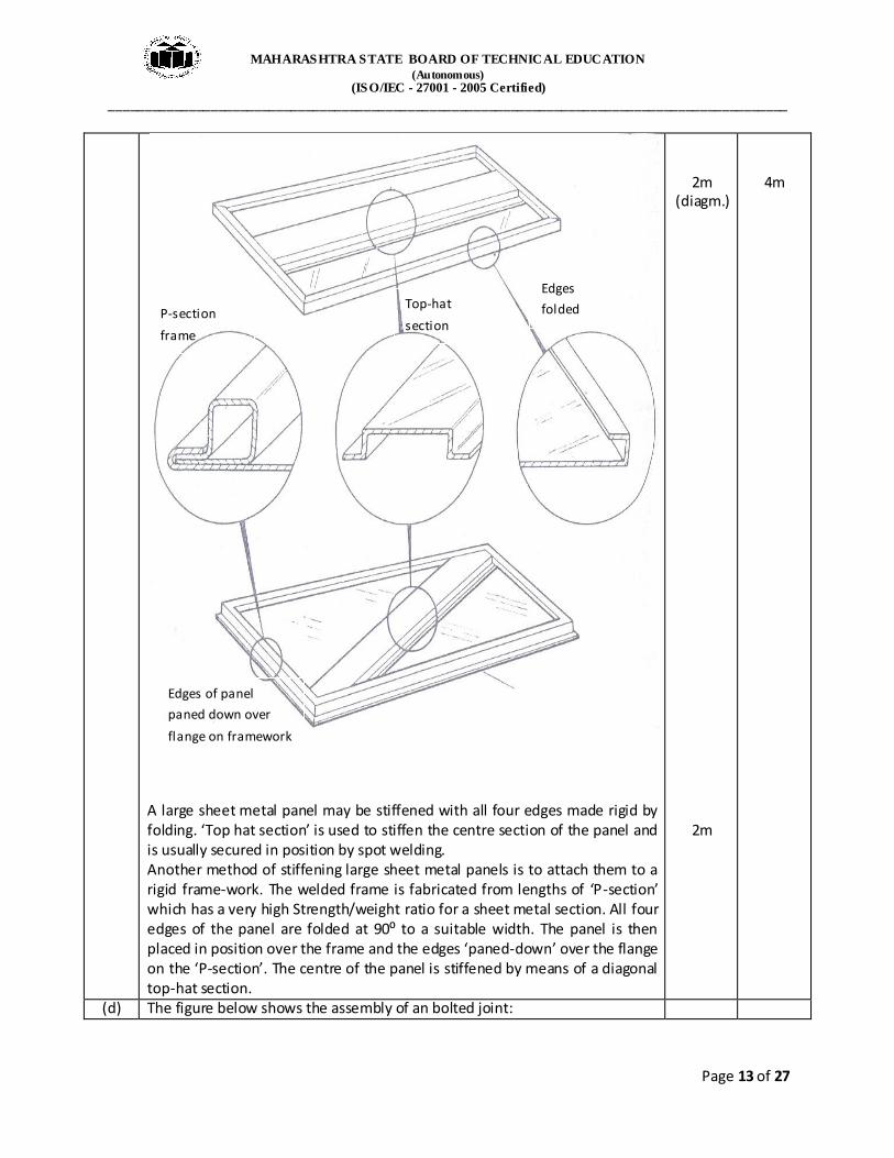
A large sheet metal panel may be stiffened with all four edges made rigid by folding. ‘Top hat section’ is used to stiffen the centre section of the panel and is usually secured in position by spot welding. Another method of stiffening large sheet metal panels is to attach them to a rigid frame-work. The welded frame is fabricated from lengths of ‘P-section’ which has a very high Strength/weight ratio for a sheet metal section. All four edges of the panel are folded at 90⁰ to a suitable width. The panel is then placed in position over the frame and the edges ‘paned-down’ over the flange on the ‘P-section’. The centre of the panel is stiffened by means of a diagonal top-hat section.
2m (diagm.)
2m
4m
(d) The figure below shows the assembly of an bolted joint:
P-section
frame
Top-hat
section
Edges
folded
Edges of panel
paned down over
flange on framework

MAHARASHTRA STATE BOARD OF TECHNICAL EDUCATION
(Autonomous) (ISO/IEC - 27001 - 2005 Certified)
_____________________________________________________________________________________________
Page 14 of 27
(e) • Mechanical drive systems: i) This has a fixed tonnage and delivers more force at the bottom of its
stroke than at the half-way point. ii) Mechanical drives will cycle its ram at more strokes per minute than a
hydraulically driven system of the same size. iii) The electric motor provides power to a flywheel which stores energy and
provides speed and consistancy of motion to the drive shaft on a mechanical system.
iv) The ram starts at high speed from the top of the stroke and automatically changes into low speed for the operating position of the stroke. At the bottom of its stroke, the ram again transfers into high speed for its return. A control mechanism provides short, medium and long periods of time for the ram at slow speeds.
v) Mechanical press brakes are easier to overload. vi) Difficult to bring ram close to material for scribed line work. Difficult to
control bending speeds. vii) Skilled operator needed to slip clutch. Clutches requirs adjusting. viii) Mechanical press brakes do not enable you to adjust the stroke length.
You must complete the revolution and cycle the machine completely, you cannot return the ram at any position of the stroke.
2m (any 4)
4m

MAHARASHTRA STATE BOARD OF TECHNICAL EDUCATION
(Autonomous) (ISO/IEC - 27001 - 2005 Certified)
_____________________________________________________________________________________________
Page 15 of 27
• Hydraulic drive systems: i) These are available with pressing capacities upto 8000 tonnes. ii) A mechanically driven press brake of equal tonnage will not deliver the
same pressure at the bottom of their strokes, it is rated at midstroke. iii) The hydraulic press brakes delivers its rated capacity over the entire
stroke. The hydraulically driven press brake's tonnage and ram speed are variable upto the machine's rated limits.
iv) A hydraulic drive allows a longer ram stroke than mechanical driven equipment.
v) The ram speed control on a hydraulic press allows the best adjustments of the material being worked.
vi) The tonnage of a hydraulic press brake is a function of the size of its cylinders, pump and circuit capacity. The hydraulic press brake's fixed tonnage cannot be surpassed so the brake can be bottomed at full tonnage repeatedly without risk. This is its advantage over the mechanical press brakes.
vii) The hydraulic driven ram will stop when it reaches the selected tonnage. It can be withdrawn from any point on the job.
viii) It is possible for the ram to be positioned within a thousandth of an inch. A job requiring repetition can be set up to produce identical parts in minutes. This capability is not available with mechanical press brakes.
ix) The hydraulic press brakes delivers full rated power throughout its stroke and has a longer stroke than a mechanical brake which is limited in stroke length by its crankshaft design.
2m
(any 4)
(B) Attempt any ONE: 06 (a) A press brake is used for bending metal. These are designed to deliver
accurate vertical blows. It is a versatile type of fabricating equipment, ideal for many metal forming operations with its ability to deliver force in a confined longitudinal area.
Disadvantages of fly press: • Slower manual operation
• Extensive manual intervention
• Difficulty in supervision of variety in jobs
•Disuniformity in job processing where pressure applied may vary from person to person
Advantages:
• Feasible for single/mass production
• Maintenance cost is low • Easily portable
• Low initial cost
2m (any 2)
2m
(any 2)
4m
(b) Composite material is a material composed of two or more distinct phases (matrix phase and dispersed phase) and having bulk properties significantly
2m
6m

MAHARASHTRA STATE BOARD OF TECHNICAL EDUCATION
(Autonomous) (ISO/IEC - 27001 - 2005 Certified)
_____________________________________________________________________________________________
Page 16 of 27
different form those of any of the constituents. Matrix phase: The primary phase, having a continuous character, is called matrix. Matrix is usually more ductile and less hard phase. It holds the dispersed phase and shares a load with it. Dispersed (reinforcing) phase: The second phase (or phases) is embedded in the matrix in a discontinuous form. This secondary phase is called dispersed phase. Dispersed phase is usually stronger than the matrix, therefore it is sometimes called reinforcing phase. There are two classification systems of composite materials. One of them is based on the matrix material (metal, ceramic, polymer) and the second is based on the material structure: Classification of composites: 1) Based on matrix material
• Metal Matrix Composites (MMC) • Ceramic Matrix Composites (CMC) • Polymer Matrix Composites (PMC)
2) Based on reinforcing material structure
• Particulate Composites: a) Composites with random orientation of particles b) Composites with preferred orientation of particles
• Fibrous Composites a) Short-fiber reinforced composites. Composites with random orientation of fibers. Composites with preferred orientation of fibers. b) Long-fiber reinforced composites Unidirectional orientation of fibers. Bidirectional orientation of fibers (woven).
• Laminate Composites: When a fiber reinforced composite consists of
several layers with different fiber orientations, it is called multilayer (angle-ply) composite.
4m
5. Attempt any TWO: 16 (a) (i)Flame lighting:
The procedure used for lighting a welding torch is adopted when lighting a cutting torch, but with some difference. The fuel gas regulator is set to the correct working pressure in the normal way and the oxygen regulator is set to the correct working pressure with the cutting oxygen valve on the torch in the open position. --- The fuel gas is lit and the flame adjusted, until it ceases to smoke. --- The heating oxygen valve is then opened and adjusted (similar to a neutral
3m
8m

MAHARASHTRA STATE BOARD OF TECHNICAL EDUCATION
(Autonomous) (ISO/IEC - 27001 - 2005 Certified)
_____________________________________________________________________________________________
Page 17 of 27
flame setting) until there is a series of nicely defined white inner cones in the flame (in the case of the multi-port type nozzle) or a short white conical ring, if the nozzle is of the annular port type.
--- The cutting oxygen valve is then opened at this stage and the flame readjusted to a neutral condition. The oxygen cutting valve is then closed and the torch is ready for use.
(ii)Flame adjustment: When oxy-propane is used for cutting, the correctly adjusted pre-heating flame will be indicated by a small non-luminous central cone with a pale blue envelope. In the case of oxy-natural gas the flame is adjusted until the luminous inner cone has a clear definite shape, usually up to 8-10mm in length).
(iii)Extinguish the flame: The correct procedure to extinguish the flame is as follows; --- Turn off the cutting oxygen. --- Close the fuel gas control valve. --- Close the heating oxygen control valve.
3m
2m
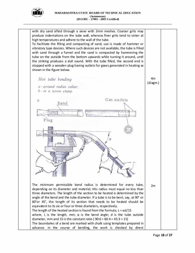
(b) Hot bending is used for tubing over 100mm in diameter. In hot bending with a filler, the tube is annealed, layed out and one end is stopped with a wooden or metal plug. To prevent its crushing, bulging or cracking, the tube is filled
2m
8m
MAHARASHTRA STATE BOARD OF TECHNICAL EDUCATION
(Autonomous) (ISO/IEC - 27001 - 2005 Certified)
_____________________________________________________________________________________________
Page 18 of 27
with dry sand sifted through a sieve with 2mm meshes. Coarser grits may produce indentations on the tube wall, whereas finer grits tend to sinter at high temperatures and adhere to the wall of the tube. To facilitate the filling and compacting of sand, use is made of hammer or vibratory type devices. Where such devices are not available, the tube is filled with sand through a funnel and the sand is compacted by hammering the tube on the outside from the bottom upwards while turning it around, until the striking produces a dull sound. With the tube filled, the second end is stopped with a wooden plug having outlets for gases generated in heating as shown in the figure below.
The minimum permissible bend radius is determined for every tube, depending on its diameter and material; this radius must equal no less than three diameters. The length of the section to be heated is determined by the angle of the bend and the tube diameter. If a tube is to be bent, say, at 90° or 60°or 45°, the length of its section that needs to be heated should be equivalent to its six or four or three diameters, respectively. The length of the heated section is found from the formula, L = αd/15 where, L is the length, mm; α is the bend angle; d is the tube outside diameter, mm and 15 is the constant ratio ( 90:6 = 60:4 = 45:3 = 15) The boundaries of a bend are marked with chalk using templates prepared in advance. In the course of bending, the work is checked by direct
4m (diagm.)
2m

MAHARASHTRA STATE BOARD OF TECHNICAL EDUCATION
(Autonomous) (ISO/IEC - 27001 - 2005 Certified)
_____________________________________________________________________________________________
Page 19 of 27
measurement or by comparison with a wire template. Tubes are heated red hot with blow lamps, in furnaces or with gas burners. If the tube has been overheated prior to bending, it is cooled down to a cherry-red colour. As repeated heating downgrades the metal, it is advisable to bend in a single-heating cycle. Local overheating is impermissible and it must be eliminated by cooling with water. When handling hot tubing, the operator must put on mittens. After bending as shown in the figure above the plugs are extracted or burnt out and the sand is removed. Poor compacting of sand and inadequate or non-uniform heating before the operation may cause the formation of folds or even rupture of the tube.
OR For bending in a screw clamp, the heated pipe is inserted in between the recessed jaws of the clamp as shown in the figure below and secured by rotating its handle. With welded tubing, the weld must be on the outside of the bend, because otherwise the tube may crack at the seam. A length of pipe is put on the end of the work so that its end comes just short of the bend, and it is forced with both hands in the required direction.
4m
4m (diagm.)
(c) The mechanics of bending: When a bending force is gradually applied to a workpiece under free bending conditions, the first stage of bending is elastic in character. This is because the tensile and compressive stresses that are developed on opposite faces of the material are not sufficiently high to
4m
8m

MAHARASHTRA STATE BOARD OF TECHNICAL EDUCATION
(Autonomous) (ISO/IEC - 27001 - 2005 Certified)
_____________________________________________________________________________________________
Page 20 of 27
exceed the yield strength of the material. The movement or strain which takes place as a result of this initial bending force is elastic only, and upon removal of the force the workpiece returns to its original shape. As the bending force is continued and gradually increased, the stress produced in the outermost fibres of the material eventually exceeds the yield strength. Once the yield strength of the material has been exceeded, the movement or strain which occurs is plastic. This permanent strain occurs only in the outermost regions furthest from the neutral plane. Between the outermost fibres and the neutral plane there is a zone where the strain produced is elastic. On release of the bending force, that portion adjacent to the neutral plane loses its elastic stress, whilst the outer portions, which have suffered plastic deformation, remain as a permanent set. Thus the elastic recovery of shape in this zone on removal of the bending force is known as ‘springback’.
1m
1m
1m
1m
6. Attempt any FOUR: 16

MAHARASHTRA STATE BOARD OF TECHNICAL EDUCATION
(Autonomous) (ISO/IEC - 27001 - 2005 Certified)
_____________________________________________________________________________________________
Page 21 of 27
(a) 1. Pre forming: Pre-forming of ends, prior to rolling of plates and sheet metals is important to obtain a true cylinder without flats where the opposite edges touch.Pinch rolls are designed to eliminate these flats at the start of the rolling operation, but other methods have to be employed when pyramid rolls are used. Briefly, some of the common methods used are as given below: i) Using a template to check the curve, hammer the ends over the bottom roller in increments as shown in fig. a. This method is used for thin gauge plate to approximately 6mm. ii) Using a convex bar between the bottom roller and the edge of the plate as shown in fig.b. This method is used for thin gauge plate to approximately 10mm. iii) ‘V’ block and top tool as shown in fig.c is used for thin and thick plates. iv) Pressing between blocks (hot or cold) as shown in fig.d for very thick plates.
2. Partial loading of the plate on the pyramid roll is carried out and allowed to set for some time depending on the pre determined load. 3. Checking the roll obtained with a pre designed template. 4. Increase the load incrementally as designed with set time and check with template for trueness and concentricity.
1m
1m (diagm.)
2m
4m
a b
c
d

MAHARASHTRA STATE BOARD OF TECHNICAL EDUCATION
(Autonomous) (ISO/IEC - 27001 - 2005 Certified)
_____________________________________________________________________________________________
Page 22 of 27
5. Complete the roll and check with template . 6. Tack weld the meeting edges. 7. Perform the longitudinal seam joint. 8. Evaluate the weld efficiency by NDT.
(b)
Parameters Bolting Riveting
Cost Low cost High cost
Reliability Less High
Labor skills Unskilled to semi - skilled Semi – skilled to skilled Joint strength
Low (fluctuating loads) High (fluctuating loads)
4m 4m
(c) Briv (Blind rivet) system: There are many other kinds of rivet used for
joining sheet metal but the pop rivet is one of the most popular. It is fitted into the drilled hole and formed either by using lazy tongs or a
plier type tool. Applications are in assembly of light fabrications, vehicle panels, ductwork and containers, used for all open blind riveting locations for normal materials with no structural or access
problems.
The rivet is a hollow tube of relatively soft material with a formed head on one side. The rivet is pre-assembled on a headed mandrel made
from a stronger material than the rivet, the plain end of the mandrel projecting a relatively high distance through the head of the hollow
rivet. The rivet shank is inserted through the hole in the parts to be joined such that it projects a set distance out of the far end of the hole. The mandrel is pulled through the rivet using a special tool causing the projecting end to be upset. The mandrel is engineered to snap at a set tension resulting in the correct formed head on the far side and the joint being under compression.
2m
2m
4m

MAHARASHTRA STATE BOARD OF TECHNICAL EDUCATION
(Autonomous) (ISO/IEC - 27001 - 2005 Certified)
_____________________________________________________________________________________________
Page 23 of 27
OR The ability to set blind rivets without the need for access at the back of the work makes their use mandatory in many instances. They are ideal for limited access installations. Minimum back-up clearance is needed.
However, their many additional advantages make blind rivets the logical choice in numerous applications where the blind-setting
feature is not of primary importance.
2m
2m
(d) Thermoset resins, are usually liquids or low melting point solids in their initial form. When used to produce finished goods, these thermosetting resins are “cured” by the use of a catalyst, heat or a combination of the two. Once cured, solid thermoset resins cannot be converted back to their original liquid form. Unlike thermoplastic resins, cured thermosets will not melt and flow but will soften when heated (and lose hardness) and once formed they cannot be reshaped. The most common thermosetting resins used in the composite industries are unsaturated polyesters, epoxies, vinyl esters, phenolics and polyurethane. Composites is the fastest growing materials market segment. Sporting goods, air-craft, automobiles, ship-building, are just a few examples. Tennis rackets, golf clubs, bumpers, door panels, dashboards and even engine components of modern automobiles, etc.
2m
2m
4m
(e) Tightening of HSFG bolts: Each bolt is assembled with one washer in cases where plane parallel surfaces are involved. The washer is placed under the bolt head or nut, whichever is to be rotated during the tightening operation (A tapered washer must be used if angle is above 3°). Driving of bolts is not permitted. If, after final tightening, a nut or bolt is slackened off, it must not be used again.
2m (diagm.)
& 2m
(expln.)
4m

MAHARASHTRA STATE BOARD OF TECHNICAL EDUCATION
(Autonomous) (ISO/IEC - 27001 - 2005 Certified)
_____________________________________________________________________________________________
Page 24 of 27
Since it is important that the torque on the nuts is correct for the bolt, a pre-calibrated impact wrench is used, or the part-turn method, or a feeler gauge if load indicating bolts or washers are being used as shown in the figures below. (Bolts must be tightened in a definite sequence).
Turn of Nut (Part Turn Method):
MAHARASHTRA STATE BOARD OF TECHNICAL EDUCATION
(Autonomous) (ISO/IEC - 27001 - 2005 Certified)
_____________________________________________________________________________________________
Page 25 of 27
After snugging the joint, the bolt shank and nut is marked and then a specific amount of rotation is induced between the nut and the bolt. The amount of rotation differs for different bolt lengths and diameters and therefore must be known and understood by the bolt installers in advance. The success of the method is dependent on a correct snugging of the joint, and is dependent on the bolt head being held from turning so the bolt does not spin in the hole. Two persons are therefore mandatory to execute this method correctly: one to hold the bolt from turning or "rolling" and the other person to operate the wrench. Note: Turn-of-nut does not work correctly when the steel surfaces are coated with a compressible coating such as high paint thickness or hot dipped galvanized zinc. Nut rotation requirements for tensioning the Friction type bolts by the part-turn method:
Bolt length (measured from underside of head to end of bolt)
Nut rotation
Upto and including four bolt diameters
One-third to five-twelfths of a turn
Over four but less than eight diameters
One-half to seven-twelfths of a turn
Over eight but less than twelve diameters
Two-thirds to three quarters of turn
OR
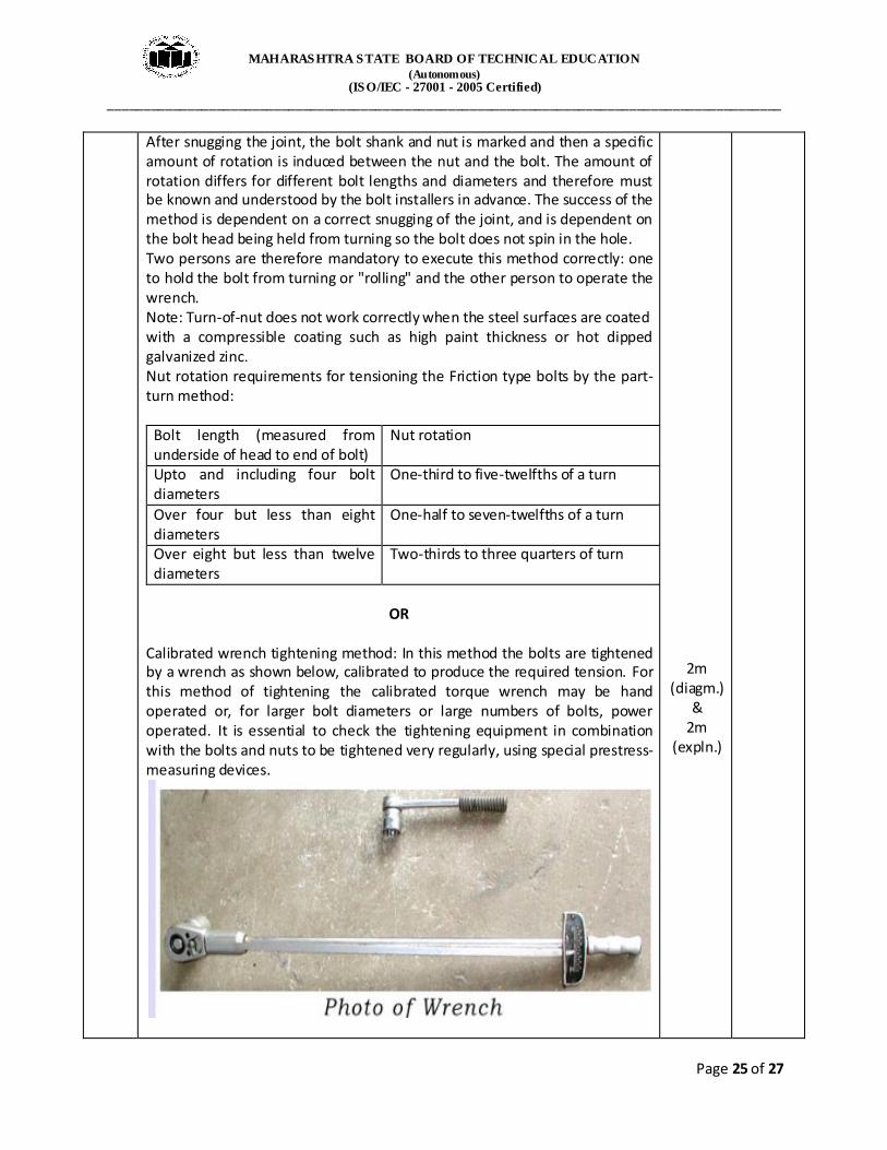
Calibrated wrench tightening method: In this method the bolts are tightened by a wrench as shown below, calibrated to produce the required tension. For this method of tightening the calibrated torque wrench may be hand operated or, for larger bolt diameters or large numbers of bolts, power operated. It is essential to check the tightening equipment in combination with the bolts and nuts to be tightened very regularly, using special prestress-measuring devices.
2m (diagm.)
& 2m
(expln.)

MAHARASHTRA STATE BOARD OF TECHNICAL EDUCATION
(Autonomous) (ISO/IEC - 27001 - 2005 Certified)
_____________________________________________________________________________________________
Page 26 of 27
OR Load indicating bolts:
As shown in the diagram above, the bolt tightening is checked with the gap present by the use of a feeler gauge. Tightening is stopped when the gap is as per the manufacturer’s specification.
OR Load indicating washer:
2m (diagm.)
& 2m
(expln.)
2m
(diagm.) &
2m (expln.)

MAHARASHTRA STATE BOARD OF TECHNICAL EDUCATION
(Autonomous) (ISO/IEC - 27001 - 2005 Certified)
_____________________________________________________________________________________________
Page 27 of 27
The ‘Coronet’ load indicator is a specially hardened washer with protrusions on one face. They bear against the underside of the bolt head leaving a gap. As the bolt is tightened, the protrusions are flattened and the gap is reduced. At a specified average gap, measured by a feeler gauge, the induced shank tension should not be less than the minimum required by standards.
(f) Composites is the fastest growing materials market segment. Sporting goods, air-craft, automobiles, ship-building, are just a few examples. Tennis rackets, golf clubs, bumpers, door panels, dashboards and even engine components of modern automobiles, etc.
4m (any 4)
4m