Embed Size (px)
Citation preview

November 2012 704-0116-415 Revision B
WINMAX MILL
OPTIONS
Dual Screen and Max Consoles
ii - WinMax Mill Options 704-0116-415 WinMax Mill Options
The information in this document is subject to change without notice and does not represent a commitment on the part of Hurco Companies, Inc. (Hurco). The software described in this document is furnished under the License Agreement to customers. It is against the law to copy the software on any medium except as specifically allowed in the license agreement. The purchaser may make copies of the software for backup purposes. No part of this document may be reproduced or transmitted in any form or by any means, electronic or mechanical, including photocopying, for any purpose without the express written permission of the Hurco machine tool owner.
Hurco Manufacturing Company reserves the right to incorporate any modification or improvements in machines and machine specifications which it considers necessary, and does not assume any obligation to make any said changes in machines or equipment previously sold.
Hurco products and services are subject to Hurco’s then current prices, terms, and conditions, which are subject to change without notice.
© 2012 Hurco Companies, Inc. All rights reserved.
Patents: U.S. Patents B14,477,754; 5,453,933; Canadian Patent 1,102,434; Japanese Patents 1,649,006 and 1,375,124; other Patents pending.
Hurco, Max, Ultimax, and WinMax are Registered Trademarks of Hurco Companies, Inc.
AutoCAD, Autodesk, and DXF are registered trademarks of Autodesk, Inc.
MS-DOS, Microsoft, and Windows are registered trademarks of Microsoft Corporation.
Many of the designations used by manufacturers and sellers to distinguish their products are claimed as trademarks. Hurco has listed here all trademarks of which it is aware. For more information about Hurco products and services, contact:
Hurco Companies, Inc. One Technology WayP.O. Box 68180Indianapolis, IN 46268-0180Tel (317) 293-5309 (products)
(317) 298-2635 (service)Fax (317) 328-2812 (service)
For Hurco subsidiary contact information, go to Hurco’s Web site:www.hurco.com
WinMax Mill Options 704-0116-415 Table of Contents -iii
TABLE OF CONTENTS
WinMax Mill Options
Documentation Conventions . . . . . . . . . . . . . . . . . . . . . . . . . . . . . . . . . . . . . xiiiConsole Buttons and Keys . . . . . . . . . . . . . . . . . . . . . . . . . . . . . . . . . . . . xiiiIcons . . . . . . . . . . . . . . . . . . . . . . . . . . . . . . . . . . . . . . . . . . . . . . . . . . xiii
Programming and Operation Information . . . . . . . . . . . . . . . . . . . . . . . . . . . . xvUsing the On-screen Help . . . . . . . . . . . . . . . . . . . . . . . . . . . . . . . . . . . . xvPrinting the Programming Manuals . . . . . . . . . . . . . . . . . . . . . . . . . . . . . . xvi
3D Mold . . . . . . . . . . . . . . . . . . . . . . . . . . . . . . . . . . . . . . . . . . . . . . . . . . .1 - 13D Mold Parameters . . . . . . . . . . . . . . . . . . . . . . . . . . . . . . . . . . . . . . . .1 - 23D Mold Contour . . . . . . . . . . . . . . . . . . . . . . . . . . . . . . . . . . . . . . . . . .1 - 93D Mold Line . . . . . . . . . . . . . . . . . . . . . . . . . . . . . . . . . . . . . . . . . . . . .1 - 103D Mold Arc . . . . . . . . . . . . . . . . . . . . . . . . . . . . . . . . . . . . . . . . . . . . . .1 - 113D Mold Blend Arc . . . . . . . . . . . . . . . . . . . . . . . . . . . . . . . . . . . . . . . . .1 - 12Roughing and Finishing Tools . . . . . . . . . . . . . . . . . . . . . . . . . . . . . . . . . .1 - 13Roughing and Finishing Passes . . . . . . . . . . . . . . . . . . . . . . . . . . . . . . . . .1 - 16
DXF Option . . . . . . . . . . . . . . . . . . . . . . . . . . . . . . . . . . . . . . . . . . . . . . . . .2 - 1DXF Overview . . . . . . . . . . . . . . . . . . . . . . . . . . . . . . . . . . . . . . . . . . . .2 - 2DXF Build Data Block . . . . . . . . . . . . . . . . . . . . . . . . . . . . . . . . . . . . . . .2 - 3DXF Parameters . . . . . . . . . . . . . . . . . . . . . . . . . . . . . . . . . . . . . . . . . . .2 - 5
Zoom Window . . . . . . . . . . . . . . . . . . . . . . . . . . . . . . . . . . . . . . . . .2 - 5Edit Drawing . . . . . . . . . . . . . . . . . . . . . . . . . . . . . . . . . . . . . . . . . . . . .2 - 6
DXF Edit Modify - Arc . . . . . . . . . . . . . . . . . . . . . . . . . . . . . . . . . . . . .2 - 8DXF Edit Modify - Line . . . . . . . . . . . . . . . . . . . . . . . . . . . . . . . . . . . .2 - 8DXF Edit Modify - Point . . . . . . . . . . . . . . . . . . . . . . . . . . . . . . . . . . . .2 - 8
DXF Layers . . . . . . . . . . . . . . . . . . . . . . . . . . . . . . . . . . . . . . . . . . . . . .2 - 9
Helical Plunge Option . . . . . . . . . . . . . . . . . . . . . . . . . . . . . . . . . . . . . . . . . .3 - 1Helical Plunge Milling Parameter Fields . . . . . . . . . . . . . . . . . . . . . . . . . . .3 - 2Helical Plunge (Inside/Outside) for Mill Frames, Mill Circles and Ellipses . . . .3 - 4Helical Plunge with UltiPocket . . . . . . . . . . . . . . . . . . . . . . . . . . . . . . . . . .3 - 4Helical Plunge with Operator Specified Location . . . . . . . . . . . . . . . . . . . . .3 - 4Helical Plunge in the Center of a Pocket . . . . . . . . . . . . . . . . . . . . . . . . . . .3 - 4Helical Plunge with Outward Pocketing . . . . . . . . . . . . . . . . . . . . . . . . . . .3 - 5Helical Plunge of Mill Frame Inside with No Pecking and Blend Offset . . . . . .3 - 5Helical Plunging of Mill Frame Inside with Pecking and Straight Plunge Finish Pass and Blend Offset . . . . . . . . . . . . . . . . . . . . . . . . . . . . . . . . . . . . . . . . . . . . . .3 - 6Helical Plunge with Lines and Arcs . . . . . . . . . . . . . . . . . . . . . . . . . . . . . .3 - 8
Helical Plunge with 3-D Part Programming Option . . . . . . . . . . . . . . . . .3 - 8
Insert Pockets . . . . . . . . . . . . . . . . . . . . . . . . . . . . . . . . . . . . . . . . . . . . . . .4 - 1Mill Triangle Data Block . . . . . . . . . . . . . . . . . . . . . . . . . . . . . . . . . . . . . .4 - 2Mill Diamond Data Block . . . . . . . . . . . . . . . . . . . . . . . . . . . . . . . . . . . . .4 - 4Mill Hexagon Data Block . . . . . . . . . . . . . . . . . . . . . . . . . . . . . . . . . . . . .4 - 7
Rotary . . . . . . . . . . . . . . . . . . . . . . . . . . . . . . . . . . . . . . . . . . . . . . . . . . . .5 - 1Rotary Overview . . . . . . . . . . . . . . . . . . . . . . . . . . . . . . . . . . . . . . . . . . .5 - 2

- iv Table of Contents 704-0116-415 WinMax Mill Options
Rotary Axis . . . . . . . . . . . . . . . . . . . . . . . . . . . . . . . . . . . . . . . . . . . .5 - 3Tilt Axis . . . . . . . . . . . . . . . . . . . . . . . . . . . . . . . . . . . . . . . . . . . . . .5 - 3Configuration of Hurco Machining Centers . . . . . . . . . . . . . . . . . . . . . .5 - 3Transform Plane . . . . . . . . . . . . . . . . . . . . . . . . . . . . . . . . . . . . . . . .5 - 5
Rotary Part Setup . . . . . . . . . . . . . . . . . . . . . . . . . . . . . . . . . . . . . . . . . .5 - 8Rotary Centerline . . . . . . . . . . . . . . . . . . . . . . . . . . . . . . . . . . . . . . .5 - 8
Rotary Part Programming . . . . . . . . . . . . . . . . . . . . . . . . . . . . . . . . . . . .5 - 10Rotary New Block . . . . . . . . . . . . . . . . . . . . . . . . . . . . . . . . . . . . . . .5 - 10Rotary Position Block . . . . . . . . . . . . . . . . . . . . . . . . . . . . . . . . . . . . .5 - 11Rotary Milling New Block . . . . . . . . . . . . . . . . . . . . . . . . . . . . . . . . . .5 - 12Rotary Patterns . . . . . . . . . . . . . . . . . . . . . . . . . . . . . . . . . . . . . . . . .5 - 12Rotary Parameters . . . . . . . . . . . . . . . . . . . . . . . . . . . . . . . . . . . . . . .5 - 13
Rotary A and Rotary A Tilt B Configuration . . . . . . . . . . . . . . . . . . . . . . . .5 - 14Rotary Position . . . . . . . . . . . . . . . . . . . . . . . . . . . . . . . . . . . . . . . . .5 - 14Rotary Lines and Arcs . . . . . . . . . . . . . . . . . . . . . . . . . . . . . . . . . . . .5 - 14Rotary Circle . . . . . . . . . . . . . . . . . . . . . . . . . . . . . . . . . . . . . . . . . . .5 - 16Rotary Frame . . . . . . . . . . . . . . . . . . . . . . . . . . . . . . . . . . . . . . . . . .5 - 16Rotary Patterns . . . . . . . . . . . . . . . . . . . . . . . . . . . . . . . . . . . . . . . . .5 - 17Rotary Parameters . . . . . . . . . . . . . . . . . . . . . . . . . . . . . . . . . . . . . . .5 - 19
Tilt A Rotary C Configuration . . . . . . . . . . . . . . . . . . . . . . . . . . . . . . . . . .5 - 20Rotary Position . . . . . . . . . . . . . . . . . . . . . . . . . . . . . . . . . . . . . . . . .5 - 20Rotary Lines and Arcs . . . . . . . . . . . . . . . . . . . . . . . . . . . . . . . . . . . .5 - 20Rotary Circle . . . . . . . . . . . . . . . . . . . . . . . . . . . . . . . . . . . . . . . . . . .5 - 22Rotary Frame . . . . . . . . . . . . . . . . . . . . . . . . . . . . . . . . . . . . . . . . . .5 - 22Rotary Patterns . . . . . . . . . . . . . . . . . . . . . . . . . . . . . . . . . . . . . . . . .5 - 23Rotary Parameters . . . . . . . . . . . . . . . . . . . . . . . . . . . . . . . . . . . . . . .5 - 25
Rotary B Configuration . . . . . . . . . . . . . . . . . . . . . . . . . . . . . . . . . . . . . .5 - 26Rotary Position . . . . . . . . . . . . . . . . . . . . . . . . . . . . . . . . . . . . . . . . .5 - 26Rotary Milling . . . . . . . . . . . . . . . . . . . . . . . . . . . . . . . . . . . . . . . . . .5 - 26Rotary Patterns . . . . . . . . . . . . . . . . . . . . . . . . . . . . . . . . . . . . . . . . .5 - 26Rotary Parameters . . . . . . . . . . . . . . . . . . . . . . . . . . . . . . . . . . . . . . .5 - 28
Tilt B Rotary C Configuration . . . . . . . . . . . . . . . . . . . . . . . . . . . . . . . . . .5 - 29Rotary Position . . . . . . . . . . . . . . . . . . . . . . . . . . . . . . . . . . . . . . . . .5 - 29Rotary Lines and Arcs . . . . . . . . . . . . . . . . . . . . . . . . . . . . . . . . . . . .5 - 29Rotary Circle . . . . . . . . . . . . . . . . . . . . . . . . . . . . . . . . . . . . . . . . . . .5 - 31Rotary Frame . . . . . . . . . . . . . . . . . . . . . . . . . . . . . . . . . . . . . . . . . .5 - 31Rotary Patterns . . . . . . . . . . . . . . . . . . . . . . . . . . . . . . . . . . . . . . . . .5 - 32Rotary Parameters . . . . . . . . . . . . . . . . . . . . . . . . . . . . . . . . . . . . . . .5 - 34
Universal Rotary Configuration . . . . . . . . . . . . . . . . . . . . . . . . . . . . . . . . .5 - 35Rotary Position Block . . . . . . . . . . . . . . . . . . . . . . . . . . . . . . . . . . . . .5 - 35Rotary Lines and Arcs . . . . . . . . . . . . . . . . . . . . . . . . . . . . . . . . . . . .5 - 36Rotary Circle . . . . . . . . . . . . . . . . . . . . . . . . . . . . . . . . . . . . . . . . . . .5 - 38Rotary Frame . . . . . . . . . . . . . . . . . . . . . . . . . . . . . . . . . . . . . . . . . .5 - 38Rotary True Type Font . . . . . . . . . . . . . . . . . . . . . . . . . . . . . . . . . . . .5 - 40Rotary Slot . . . . . . . . . . . . . . . . . . . . . . . . . . . . . . . . . . . . . . . . . . . .5 - 41Rotary Polygon . . . . . . . . . . . . . . . . . . . . . . . . . . . . . . . . . . . . . . . . .5 - 43Rotary Stick Lettering . . . . . . . . . . . . . . . . . . . . . . . . . . . . . . . . . . . .5 - 45Rotary Patterns . . . . . . . . . . . . . . . . . . . . . . . . . . . . . . . . . . . . . . . . .5 - 46
Calculating X- and Z-Axis Positions After a Tilt-Axis Move . . . . . . . . . . . . . .5 - 49Part Zero Calibrated at Zero Degree Vertical . . . . . . . . . . . . . . . . . . . . .5 - 49Part Zero Calibrated at Zero Degree Horizontal . . . . . . . . . . . . . . . . . . .5 - 50
Example Programs . . . . . . . . . . . . . . . . . . . . . . . . . . . . . . . . . . . . . . . . .5 - 51Rotary Programming Examples . . . . . . . . . . . . . . . . . . . . . . . . . . . . . .5 - 51Tilt-Axis Programming Examples . . . . . . . . . . . . . . . . . . . . . . . . . . . . .5 - 60Transform Plane Example Programs . . . . . . . . . . . . . . . . . . . . . . . . . . .5 - 62

WinMax Mill Options 704-0116-415 Table of Contents -v
Post Processor (Desktop Only) . . . . . . . . . . . . . . . . . . . . . . . . . . . . . . . . . . .6 - 1
Part Probing Option . . . . . . . . . . . . . . . . . . . . . . . . . . . . . . . . . . . . . . . . . . .7 - 1Part Setup—Part Probe Parameters . . . . . . . . . . . . . . . . . . . . . . . . . . . . . .7 - 2Part Probe Calibration and Cycles . . . . . . . . . . . . . . . . . . . . . . . . . . . . . . .7 - 5
Part Probe Deflection Offset Calibration . . . . . . . . . . . . . . . . . . . . . . . .7 - 5Conversational Part Probing Cycles . . . . . . . . . . . . . . . . . . . . . . . . . . .7 - 9
Part Quality Verification . . . . . . . . . . . . . . . . . . . . . . . . . . . . . . . . . . . . . .7 - 46Part Inspection . . . . . . . . . . . . . . . . . . . . . . . . . . . . . . . . . . . . . . . . .7 - 46
Tool Probing Option . . . . . . . . . . . . . . . . . . . . . . . . . . . . . . . . . . . . . . . . . . .8 - 1Tool Probing in Absolute Tool Length Mode . . . . . . . . . . . . . . . . . . . . . . . .8 - 2
Set the Probing Parameters—Absolute Tool Length Mode . . . . . . . . . . . .8 - 2Run the Probe Cycle . . . . . . . . . . . . . . . . . . . . . . . . . . . . . . . . . . . . . .8 - 5
Tool Probing in Zero Calibration Mode . . . . . . . . . . . . . . . . . . . . . . . . . . . .8 - 8Set the Probing Parameters—Zero Calibration mode . . . . . . . . . . . . . . .8 - 8Determine Probe Z . . . . . . . . . . . . . . . . . . . . . . . . . . . . . . . . . . . . . .8 - 9Run the Probe Cycle . . . . . . . . . . . . . . . . . . . . . . . . . . . . . . . . . . . . . .8 - 11
Tool Quality Monitoring . . . . . . . . . . . . . . . . . . . . . . . . . . . . . . . . . . . . . .8 - 14Probe Tool Monitoring Data Block . . . . . . . . . . . . . . . . . . . . . . . . . . . .8 - 14Automatic Tool Monitoring Parameter . . . . . . . . . . . . . . . . . . . . . . . . . .8 - 18
Appendix A: Tool Probe Setup . . . . . . . . . . . . . . . . . . . . . . . . . . . . . . . . .8 - 19Touch Probe Parameters . . . . . . . . . . . . . . . . . . . . . . . . . . . . . . . . . . .8 - 19Laser Probe Parameters . . . . . . . . . . . . . . . . . . . . . . . . . . . . . . . . . . .8 - 21Probe Deflection Offset Calibration . . . . . . . . . . . . . . . . . . . . . . . . . . . .8 - 26
Appendix B: Tool Probe Calibration . . . . . . . . . . . . . . . . . . . . . . . . . . . . . .8 - 29Probe Calibration—Absolute Tool Length mode . . . . . . . . . . . . . . . . . . .8 - 29Probe Calibration—Zero Calibration mode . . . . . . . . . . . . . . . . . . . . . . .8 - 30
Appendix C: Probing Parameter Definitions . . . . . . . . . . . . . . . . . . . . . . . .8 - 33
Tool Change Optimization . . . . . . . . . . . . . . . . . . . . . . . . . . . . . . . . . . . . . . .9 - 1Using Tool Change Optimization . . . . . . . . . . . . . . . . . . . . . . . . . . . . . . . .9 - 1
Tool Change Review . . . . . . . . . . . . . . . . . . . . . . . . . . . . . . . . . . . . . .9 - 5Hole Blocks and Tool Change Optimization . . . . . . . . . . . . . . . . . . . . . . . . .9 - 6
Tool Fixture (TPS) Option . . . . . . . . . . . . . . . . . . . . . . . . . . . . . . . . . . . . . . .10 - 1Tool Fixture Overview . . . . . . . . . . . . . . . . . . . . . . . . . . . . . . . . . . . . . . .10 - 2Automatic Tool Removal Using TPS . . . . . . . . . . . . . . . . . . . . . . . . . . . . . .10 - 3Automatic Tool Change Using TPS . . . . . . . . . . . . . . . . . . . . . . . . . . . . . .10 - 4Bypass TPS in an Automatic Tool Change . . . . . . . . . . . . . . . . . . . . . . . . .10 - 5
UltiMotion . . . . . . . . . . . . . . . . . . . . . . . . . . . . . . . . . . . . . . . . . . . . . . . . . .11 - 1How to Select the Motion System . . . . . . . . . . . . . . . . . . . . . . . . . . . .11 - 2
UltiMonitor . . . . . . . . . . . . . . . . . . . . . . . . . . . . . . . . . . . . . . . . . . . . . . . . .12 - 1LAN Requirements . . . . . . . . . . . . . . . . . . . . . . . . . . . . . . . . . . . . . . . . .12 - 2
Limitations for UltiMonitor . . . . . . . . . . . . . . . . . . . . . . . . . . . . . . . . . .12 - 2Glossary of Networking Terms . . . . . . . . . . . . . . . . . . . . . . . . . . . . . . .12 - 2
Configuring a Network . . . . . . . . . . . . . . . . . . . . . . . . . . . . . . . . . . . . . . .12 - 4Configuring an IP address for your machine . . . . . . . . . . . . . . . . . . . . .12 - 4Configuring the Computer and Workgroup Names . . . . . . . . . . . . . . . . .12 - 6Mapping a Network Drive . . . . . . . . . . . . . . . . . . . . . . . . . . . . . . . . . .12 - 7
Using FTP . . . . . . . . . . . . . . . . . . . . . . . . . . . . . . . . . . . . . . . . . . . . . . .12 - 9FTP Server Settings . . . . . . . . . . . . . . . . . . . . . . . . . . . . . . . . . . . . . .12 - 9FTP Manager . . . . . . . . . . . . . . . . . . . . . . . . . . . . . . . . . . . . . . . . . . .12 - 11
- vi Table of Contents 704-0116-415 WinMax Mill Options
Extended Shop Floor (ESF) . . . . . . . . . . . . . . . . . . . . . . . . . . . . . . . . . . .12 - 13
UltiPockets Option . . . . . . . . . . . . . . . . . . . . . . . . . . . . . . . . . . . . . . . . . . . .13 - 1Pocket Boundary . . . . . . . . . . . . . . . . . . . . . . . . . . . . . . . . . . . . . . . . . .13 - 2
Spiral Outward - No Islands . . . . . . . . . . . . . . . . . . . . . . . . . . . . . . . .13 - 2Spiral Inward . . . . . . . . . . . . . . . . . . . . . . . . . . . . . . . . . . . . . . . . . .13 - 2Programming Islands . . . . . . . . . . . . . . . . . . . . . . . . . . . . . . . . . . . . .13 - 2Mill Contours . . . . . . . . . . . . . . . . . . . . . . . . . . . . . . . . . . . . . . . . . . .13 - 2Mill Frame . . . . . . . . . . . . . . . . . . . . . . . . . . . . . . . . . . . . . . . . . . . .13 - 3Mill Circle . . . . . . . . . . . . . . . . . . . . . . . . . . . . . . . . . . . . . . . . . . . . .13 - 3Pattern . . . . . . . . . . . . . . . . . . . . . . . . . . . . . . . . . . . . . . . . . . . . . . .13 - 3
Helical Plunge with UltiPocket Option . . . . . . . . . . . . . . . . . . . . . . . . . . . .13 - 4Helical Plunge Using Operator Specify Pocket Start . . . . . . . . . . . . . . . . . . .13 - 5
Record of Changes . . . . . . . . . . . . . . . . . . . . . . . . . . . . . . . . . . . . . . . . . . . . 1
Index . . . . . . . . . . . . . . . . . . . . . . . . . . . . . . . . . . . . . . . . . . . . . . . . . . . . .IX - 1
Machine Manual Title 704-0211-211 List of Figures A-27
LIST OF FIGURES
Figure 1–1. Increased Radius . . . . . . . . . . . . . . . . . . . . . . . . . . . . . . . . . . . . 1 - 3Figure 1–2. Zero Radius . . . . . . . . . . . . . . . . . . . . . . . . . . . . . . . . . . . . . . . 1 - 3Figure 1–3. Convex Contour Below the Part Surface . . . . . . . . . . . . . . . . . . . . 1 - 4Figure 1–4. Counterclockwise and Clockwise Motion . . . . . . . . . . . . . . . . . . . . 1 - 4Figure 1–5. Y Start and Y End Fields (XZ Translated in Y) . . . . . . . . . . . . . . . . 1 - 5Figure 1–6. Bidirectional field . . . . . . . . . . . . . . . . . . . . . . . . . . . . . . . . . . . . 1 - 6Figure 1–7. Step Size . . . . . . . . . . . . . . . . . . . . . . . . . . . . . . . . . . . . . . . . . 1 - 7Figure 1–8. Peck Depth . . . . . . . . . . . . . . . . . . . . . . . . . . . . . . . . . . . . . . . . 1 - 7Figure 1–9. Stock Allowance . . . . . . . . . . . . . . . . . . . . . . . . . . . . . . . . . . . . 1 - 8Figure 1–10.Flat End Mill on a Contour . . . . . . . . . . . . . . . . . . . . . . . . . . . . . . 1 - 13Figure 1–11.Ball-Nosed End Mill on a Contour . . . . . . . . . . . . . . . . . . . . . . . . . 1 - 13Figure 1–12.Flat End Mill . . . . . . . . . . . . . . . . . . . . . . . . . . . . . . . . . . . . . . . 1 - 14Figure 1–13. Ball-Nosed End Mill . . . . . . . . . . . . . . . . . . . . . . . . . . . . . . . . . 1 - 15Figure 1–14.Roughing and Finishing Passes . . . . . . . . . . . . . . . . . . . . . . . . . . 1 - 16
Figure 2–1. Extended Lines and Arcs . . . . . . . . . . . . . . . . . . . . . . . . . . . . . . . 2 - 6Figure 2–2. Joined Lines and Arcs . . . . . . . . . . . . . . . . . . . . . . . . . . . . . . . . . 2 - 7
Figure 3–1. Helical Plunge with No Pecking and Blend Offset (Isometric View) . . 3 - 5Figure 3–2. First Peck (Isometric View) . . . . . . . . . . . . . . . . . . . . . . . . . . . . . 3 - 6Figure 3–3. Second Peck (Isometric View) . . . . . . . . . . . . . . . . . . . . . . . . . . . 3 - 7Figure 3–4. Finish Pass (Isometric View) . . . . . . . . . . . . . . . . . . . . . . . . . . . . 3 - 7Figure 3–5. Helical Plunging with Lines/Arcs (Isometric View) . . . . . . . . . . . . . 3 - 8
Figure 4–1. Insert Pockets Softkeys . . . . . . . . . . . . . . . . . . . . . . . . . . . . . . . 4 - 1Figure 4–2. Triangle Programming Diagram . . . . . . . . . . . . . . . . . . . . . . . . . . 4 - 2Figure 4–3. Diamond 1 Face Diagram . . . . . . . . . . . . . . . . . . . . . . . . . . . . . . 4 - 4Figure 4–4. Diamond 2 Faces Diagram . . . . . . . . . . . . . . . . . . . . . . . . . . . . . 4 - 5Figure 4–5. Hexagon Diagram . . . . . . . . . . . . . . . . . . . . . . . . . . . . . . . . . . . 4 - 7
Figure 5–1. Axes Movement . . . . . . . . . . . . . . . . . . . . . . . . . . . . . . . . . . . . . 5 - 2Figure 5–2. Rotary Centerline . . . . . . . . . . . . . . . . . . . . . . . . . . . . . . . . . . . 5 - 9Figure 5–3. Rotary Centerline . . . . . . . . . . . . . . . . . . . . . . . . . . . . . . . . . . . 5 - 9Figure 5–4. Universal Rotary Frame Geometry tab . . . . . . . . . . . . . . . . . . . . . 5 - 38Figure 5–5. Universal Rotary Frame Corners tab . . . . . . . . . . . . . . . . . . . . . . . 5 - 39Figure 5–6. Universal Rotary Frame example . . . . . . . . . . . . . . . . . . . . . . . . . 5 - 39Figure 5–7. Y Mapping . . . . . . . . . . . . . . . . . . . . . . . . . . . . . . . . . . . . . . . . . 5 - 40Figure 5–8. Rotary Stick Lettering screen . . . . . . . . . . . . . . . . . . . . . . . . . . . 5 - 45Figure 5–9. Vertical Tilt-Axis Example . . . . . . . . . . . . . . . . . . . . . . . . . . . . . . 5 - 49Figure 5–10.Horizontal Tilt-Axis Example . . . . . . . . . . . . . . . . . . . . . . . . . . . . 5 - 50Figure 5–11.Rotary Mill Frame Part Drawing (cylinder shown for reference) . . . . 5 - 51Figure 5–12.Threading Part Drawing (cylinder shown for reference) . . . . . . . . . 5 - 52Figure 5–13.Single Hole Part Drawing (cylinder shown for reference) . . . . . . . . 5 - 54Figure 5–14.Rotary Pattern Loop Part Drawing (cylinder shown for reference) . . 5 - 55Figure 5–15.4-axis Part Created Using Transform Plane . . . . . . . . . . . . . . . . . . 5 - 57Figure 5–16.Bolt Holes on Tilted Cylindrical Part . . . . . . . . . . . . . . . . . . . . . . . 5 - 60Figure 5–17.Cylindrical Part Tilted 45° Between Holes . . . . . . . . . . . . . . . . . . . 5 - 61Figure 5–18.Same Part Zero for Transformed Plane, VMX42 SR Machine . . . . . . 5 - 62Figure 5–19.Part Created on VMX42SR Machine, Using Transform Plane . . . . . . 5 - 64

A - 28 List of Figures 704-0211-211 Machine Manual Title
Figure 6–1. Utilities screen with Post Processor softkey . . . . . . . . . . . . . . . . . . 6 - 1Figure 6–2. Post Processor Configuration screen . . . . . . . . . . . . . . . . . . . . . . . 6 - 1
Figure 8–1. Tool Probing screen in Absolute Tool Length mode . . . . . . . . . . . . . 8 - 2Figure 8–2. Tool Probing Cycle Defaults screen in Absolute Tool Length mode . . 8 - 4Figure 8–3. Tool Probing screen in Zero Calibration mode . . . . . . . . . . . . . . . . 8 - 8Figure 8–4. Tool Probing Cycle Defaults screen in Zero Calibration mode . . . . . 8 - 10Figure 8–1. Touch Probe Parameters . . . . . . . . . . . . . . . . . . . . . . . . . . . . . . 8 - 19Figure 8–2. Laser Probe Parameters . . . . . . . . . . . . . . . . . . . . . . . . . . . . . . . 8 - 21Figure 8–3. Typical Laser Probe Calibration Tool . . . . . . . . . . . . . . . . . . . . . . . 8 - 23Figure 8–4. Typical Laser Probe Calibration Tool Motion . . . . . . . . . . . . . . . . . 8 - 25Figure 8–5. Tool Probe Deflection Offsets . . . . . . . . . . . . . . . . . . . . . . . . . . . 8 - 26Figure 8–6. Tool Measurement Screen . . . . . . . . . . . . . . . . . . . . . . . . . . . . . 8 - 30Figure 8–7. Tool Setup Probing Parameters in Zero Calibration mode . . . . . . . . 8 - 30
Figure 9–1. Tool Change Optimization parameter in Program Parameters . . . . . 9 - 1Figure 9–2. Tool Change Optimization On block . . . . . . . . . . . . . . . . . . . . . . . 9 - 2Figure 9–3. Placement of Tool Change Optimization blocks . . . . . . . . . . . . . . . 9 - 4Figure 9–4. Tool Change Review Screen . . . . . . . . . . . . . . . . . . . . . . . . . . . . 9 - 5
Figure 10–1.Tool Fixture . . . . . . . . . . . . . . . . . . . . . . . . . . . . . . . . . . . . . . . 10 - 2
Figure 12–1.Default LAN and Internet Protocol Properties . . . . . . . . . . . . . . . . 12 - 5Figure 12–2.Computer Name Changes in System Properties . . . . . . . . . . . . . . . 12 - 6Figure 12–3.Map Network Drive dialog . . . . . . . . . . . . . . . . . . . . . . . . . . . . . . 12 - 7Figure 12–4.FTP Server Settings screen . . . . . . . . . . . . . . . . . . . . . . . . . . . . . 12 - 9Figure 12–5.FTP Host List screen . . . . . . . . . . . . . . . . . . . . . . . . . . . . . . . . . . 12 - 11Figure 12–6.FTP Host Properties screen . . . . . . . . . . . . . . . . . . . . . . . . . . . . . 12 - 11
Machine Manual Title 704-nnnn-nnn List of Tables A-29
LIST OF TABLES
Table 5–1. Rotary Configurations Available on Hurco Machines . . . . . . . . . . . .5 - 3Table 5–1. Rotary Mill Frame Part Program Summary . . . . . . . . . . . . . . . . . .5 - 52Table 5–2. Threading Part Program Summary . . . . . . . . . . . . . . . . . . . . . . . .5 - 53Table 5–3. Hole Part Program Summary . . . . . . . . . . . . . . . . . . . . . . . . . . . .5 - 54Table 5–4. Rotary Pattern Loop Part Program Summary . . . . . . . . . . . . . . . . .5 - 56Table 5–5. 4-Axis Transform Plane Program Summary . . . . . . . . . . . . . . . . . .5 - 59Table 5–6. Bolt Holes on Tilted Cylindrical Part Program Summary . . . . . . . . .5 - 60Table 5–7. Cylindrical Part Tilted 45° Between Holes Part Program Summary . .5 - 61Table 5–8. Same Part Zero for Transformed Plane Part Program Summary,
VMX42SR Machine . . . . . . . . . . . . . . . . . . . . . . . . . . . . . . . . . . .5 - 63

A - 30 List of Tables 704-nnnn-nnn Machine Manual Title
WinMax Mill Options 704-0116-415 Documentation Conventions — xiii
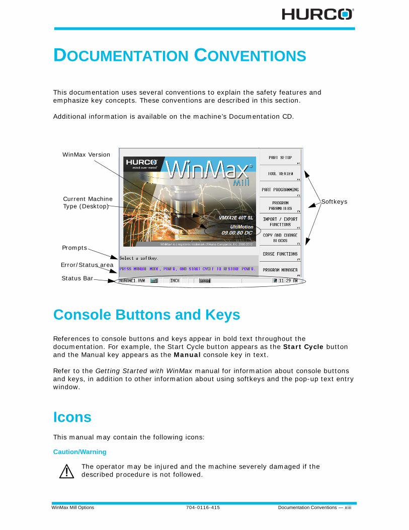
DOCUMENTATION CONVENTIONS
This documentation uses several conventions to explain the safety features and emphasize key concepts. These conventions are described in this section.
Additional information is available on the machine’s Documentation CD.
Console Buttons and Keys
References to console buttons and keys appear in bold text throughout the documentation. For example, the Start Cycle button appears as the Start Cycle button and the Manual key appears as the Manual console key in text.
Refer to the Getting Started with WinMax manual for information about console buttons and keys, in addition to other information about using softkeys and the pop-up text entry window.
IconsThis manual may contain the following icons:
Caution/Warning
The operator may be injured and the machine severely damaged if the described procedure is not followed.
Softkeys
Status Bar
Error/Status area
Prompts
WinMax Version
Current MachineType (Desktop)
xiv - Documentation Conventions 704-0116-415 WinMax Mill Options
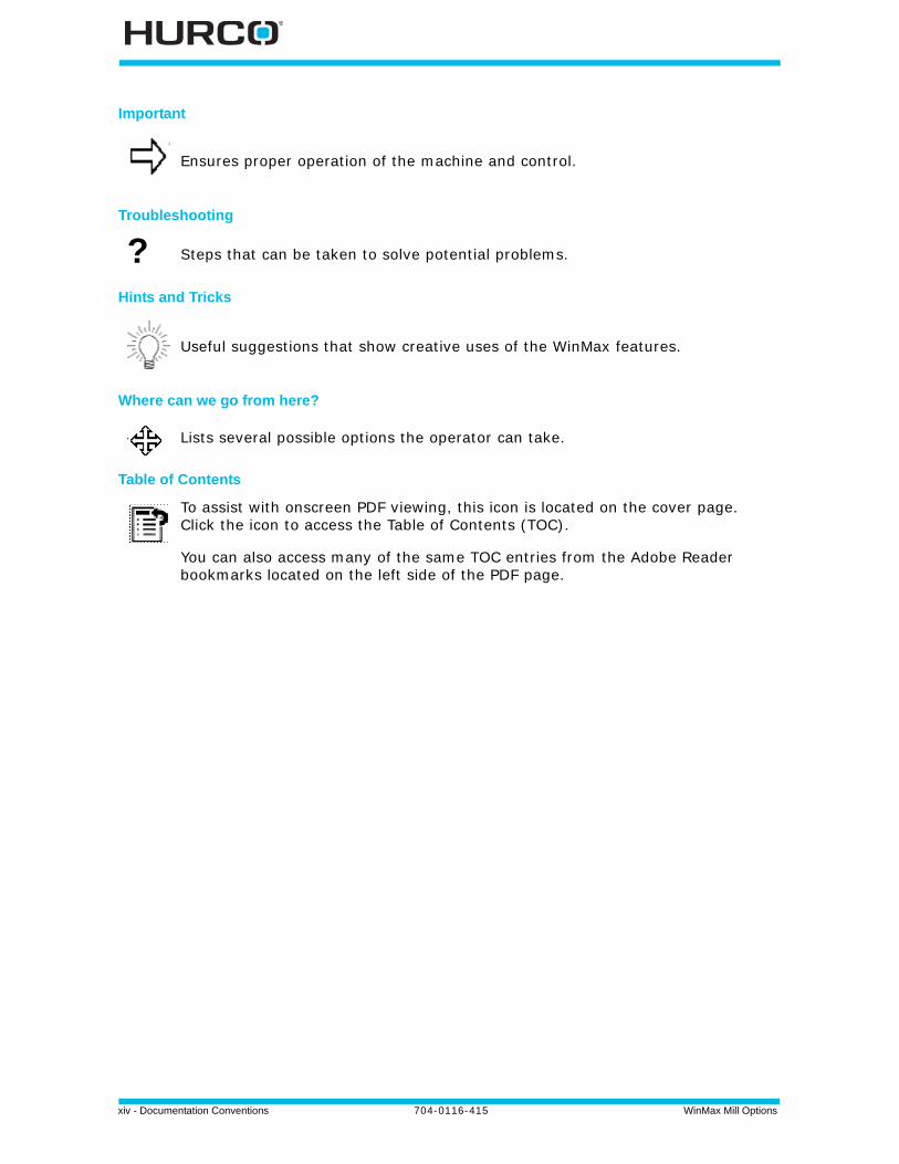
Important
Troubleshooting
Hints and Tricks
Where can we go from here?
Table of Contents
Ensures proper operation of the machine and control.
? Steps that can be taken to solve potential problems.
Useful suggestions that show creative uses of the WinMax features.
Lists several possible options the operator can take.
To assist with onscreen PDF viewing, this icon is located on the cover page. Click the icon to access the Table of Contents (TOC).
You can also access many of the same TOC entries from the Adobe Reader bookmarks located on the left side of the PDF page.
WinMax Mill Options 704-0116-415 Programming and Operation Information — xv
PROGRAMMING AND OPERATION INFORMATION
Hurco provides documentation for using WinMax software on a control or desktop in two formats: on-screen Help and PDF. The information contained in both formats is identical.
On-screen Help contains information about the current screen. If Help is not available for a screen, a Welcome screen appears with access to the Table of Contents, Index, or Search functions.
• To view the on-screen Help directly on a Hurco control, select the Help console key.
• To view the on-screen Help on the desktop software, select the Help icon in the menu bar.
PDF files are available on the hard drive. These files can be copied from the hard drive to a USB memory device and transferred to a PC for viewing and printing.
Using the On-screen Help
On-screen Help provides information about using WinMax. The Help is context-sensitive to the screen level. Press the console Help button to display the Help topic for the current screen. The following list describes Help functions:
• Buttons in the upper left-hand corner of the Help screen are used to move through Help topics and print screens.
• Use the Hide button to hide the navigation pane.
• Use the Back button to return to the previous Help screen.
• Use the Print button to print the current displayed Help topic, if a printer is attached and configured. See Printing the Programming Manuals, on page - xvi for more information about printing.
• Use the arrow buttons to move between pages within a Help topic and to move through topics.
• Use the Contents tab for a list of information sorted by subject:
1. Select the “+” to expand the topic and view sub-topics.
2. Select the topic to display it.
• Use the Index tab to show the Help index:
1. Quickly scroll to an index topic by typing the topic in the box at the top of the index.
2. Select a topic and the Display button to view the topic.
xvi - Programming and Operation Information 704-0116-415 WinMax Mill Options
• Use the Search tab to search the Help for a word or phrase:
1. Type the search word(s) into the text box at the top of the pane.
2. Select the List Topics button. A list of topics that contain the search word(s) is displayed.
3. Select a topic and the Display button to view that topic.
• Use the Favorites tab to save Help topics for quick access:
1. Select the Add button at the bottom of the pane to add the current topic.
2. Select a topic from the Favorites list, and select the Display button to view it.
• Select a topic from the Favorites list, and select the Remove button to remove it from the list.
Printing the Programming ManualsThe WinMax On-screen Help is also provided in PDF format for easy printing. The information contained in the PDF files is identical to the on-screen Help. The PDF files may be copied to a floppy disk or USB memory device to be transferred to a PC for printing. Here are the steps to access the PDF files:
1. From the Input screen, select the PROGRAM MANAGER F8 softkey.
2. Select the DISK OPERATIONS F7 softkey.
3. In the left-hand pane, navigate through the folders:
• For WinMax Mill on a machine, the path is D:\Hurco\Winmax Mill\hlp.
• For WinMax Desktop on a PC, the path is C:\Program Files\Winmax Mill\hlp.
The PDF files will appear in the right-hand pane.
4. Highlight the PDF file(s) in the right-hand pane, and select the COPY F2 softkey.
5. Ensure that your media is loaded (either a floppy disk in the disk drive or a USB memory device in the USB port), and navigate to the proper location in the left-hand pane of the DISK OPERATIONS screen (either the floppy drive A: or the USB port E:). Highlight the desired location.
6. Place the cursor in the right-hand pane and select the PASTE F3 softkey to paste the PDF file(s) to the desired location.
You may now remove your media and load the PDF file(s) onto a PC for printing.
The SHOW ALL FILE TYPES field in User Interface Settings must be set to YES (default is NO) in order to see the PDF files in the directory. Access the SHOW ALL FILE TYPES field in Auxiliary Mode, Utilities/ User Preferences/ User Interface Settings.

WinMax Mill Options 704-0116-415 — xvii

xviii - 704-0116-415 WinMax Mill Options
WinMax Mill Options 704-0116-415 3D Mold 1-1
3D MOLD
These topics are discussed in this section:
3D Mold Parameters . . . . . . . . . . . . . . . . . . . . . . . . . . . . . . . . . . . . . . . . . 1 - 2
3D Mold Contour . . . . . . . . . . . . . . . . . . . . . . . . . . . . . . . . . . . . . . . . . . . 1 - 9
3D Mold Line . . . . . . . . . . . . . . . . . . . . . . . . . . . . . . . . . . . . . . . . . . . . . . 1 - 10
3D Mold Arc . . . . . . . . . . . . . . . . . . . . . . . . . . . . . . . . . . . . . . . . . . . . . . . 1 - 11
3D Mold Blend Arc . . . . . . . . . . . . . . . . . . . . . . . . . . . . . . . . . . . . . . . . . . 1 - 12
Roughing and Finishing Tools . . . . . . . . . . . . . . . . . . . . . . . . . . . . . . . . . . . 1 - 13
Roughing and Finishing Passes . . . . . . . . . . . . . . . . . . . . . . . . . . . . . . . . . . 1 - 16
1 - 2 3D Mold 704-0116-415 WinMax Mill Options
3D Mold Parameters
To create a three-dimensional (3D) part, define a two-dimensional (2D) profile in either the XY or XZ plane. Repeat the 2D profile along a straight line (translate) or repeat it around a centerline (revolve) to produce the final 3D shape. Choose Draw 2D Contour to draw the original 2D contour that will be manipulated using the 3D operations.
To program a 3D Mold data block from the Part Programming screen, select the Insert Block Before softkey then select the Milling Softkey that appears. On the Milling softkeys, select 3D Mold.
Combine of any of the three types into composite contours to machine complex parts:
• Y Revolved about X—Use a 2D contour programmed in the XY plane and revolve it about a centerline on the X axis to produce the finished 3D contour.
• XZ Revolved about Z—Use a 2D contour programmed in the XZ plane and revolve it about a centerline on the Z axis to produce the finished 3D contour.
• XZ Translated in Y—Use a 2D contour programmed in the XZ plane and translate it in the Y axis.
Access the 3D Mold Contour screens by selecting the Edit 3D Mold Contour softkey. This softkey is not available when the cursor is in the Block field. When you select the Edit 3D Mold Contour softkey, it changes to Edit 3D Mold Parameters so you can return to the parameters screen. The Edit 3D Mold Parameters softkey is not available when the cursor is in either the Block or Segment field.
The 3D Mold Parameter fields are defined as follows:
• Block—Identifies the block number for this operation. The system determines the number by the position of this data block in the program.
• Tool—Identifies the tool number for this data block and enters that tool's diameter and type on this screen.
• Finish Tool—Identifies the finish tool number for this data block and enters that tool's diameter and type on this screen.
• Type— Defines the type of 3D operation. There are four drop-down list box and softkey choices when the cursor is on the Type field.
• Draw 2D Contour
• Y Revolved about X—Use a 2D contour programmed in the XY plane and revolve it about a centerline on the X axis to produce the finished 3D contour.
• XZ Revolved about Z—Use a 2D contour programmed in the XZ plane and revolve it about a centerline on the Z axis to produce the finished 3D contour.
• XZ Translated in Y—Use a 2D contour programmed in the XZ plane and translate it in the Y axis.
WinMax Mill Options 704-0116-415 3D Mold 1-3
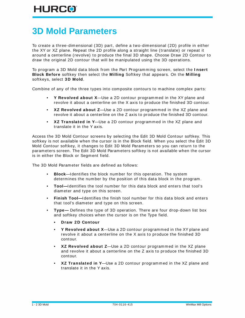
• Centerline Y and Centerline Z—Determine the coordinate points of the center of the part on the Y and Z axes.
Figure 1–1. Increased Radius
Figure 1–2. Zero Radius
1 X Centerline = 0
2 Y Centerline = 5
1 X Centerline = 0
2 Y Centerline = 0
1 - 4 3D Mold 704-0116-415 WinMax Mill Options
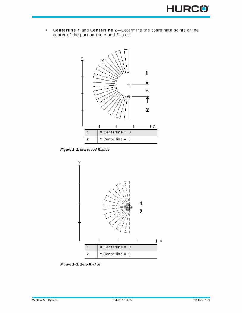
The Centerline Z field determines the Z axis position of the X axis centerline. Changing the Z axis centerline moves the X axis centerline above or below the part surface. This alters the depth of the 3D contour. The Z axis centerline is used only for XY Revolved About X.
To machine the 3D contour below the part surface, enter a negative value in the Centerline Z field. This value is equal to the radius of the part measured from the Y centerline.
Here is a convex contour programmed below the part surface:
Figure 1–3. Convex Contour Below the Part Surface
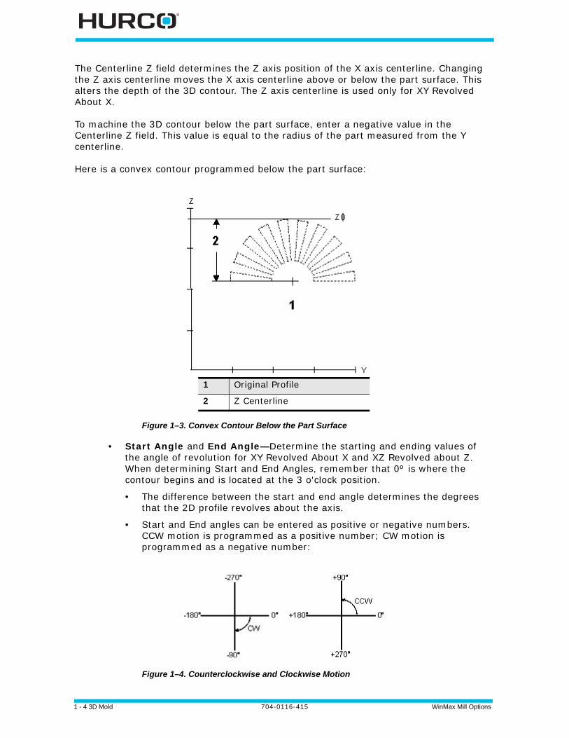
• Start Angle and End Angle—Determine the starting and ending values of the angle of revolution for XY Revolved About X and XZ Revolved about Z. When determining Start and End Angles, remember that 0º is where the contour begins and is located at the 3 o'clock position.
• The difference between the start and end angle determines the degrees that the 2D profile revolves about the axis.
• Start and End angles can be entered as positive or negative numbers. CCW motion is programmed as a positive number; CW motion is programmed as a negative number:
Figure 1–4. Counterclockwise and Clockwise Motion
1 Original Profile
2 Z Centerline

WinMax Mill Options 704-0116-415 3D Mold 1-5
• Y Start and Y End—Determine the length of the 3D contour along the Y axis for XZ Translated in Y, as shown in the example below:
Figure 1–5. Y Start and Y End Fields (XZ Translated in Y)
• Cut Direction—Controls the tool path while the 3D contour is machined. There are two choices for the Cut Direction field:
• With Contour - machines the 3D contour using the tool path originally programmed.
• Normal - tool path follows the part at right angles to the original two-dimensional profile.
1 Part Zero
2 Y Start
3 Y End

1 - 6 3D Mold 704-0116-415 WinMax Mill Options
• Bidirectional—Determines the direction of the tool path while the part is being machined. There are two choices for the Bidirectional field:
• No - causes the tool to machine in one direction, based on the direction of the contour definition.
• Yes - causes the tool to machine in both directions without retracting the tool until the entire contour is complete.
Figure 1–6. Bidirectional field
1 Yes
2 No
WinMax Mill Options 704-0116-415 3D Mold 1-7
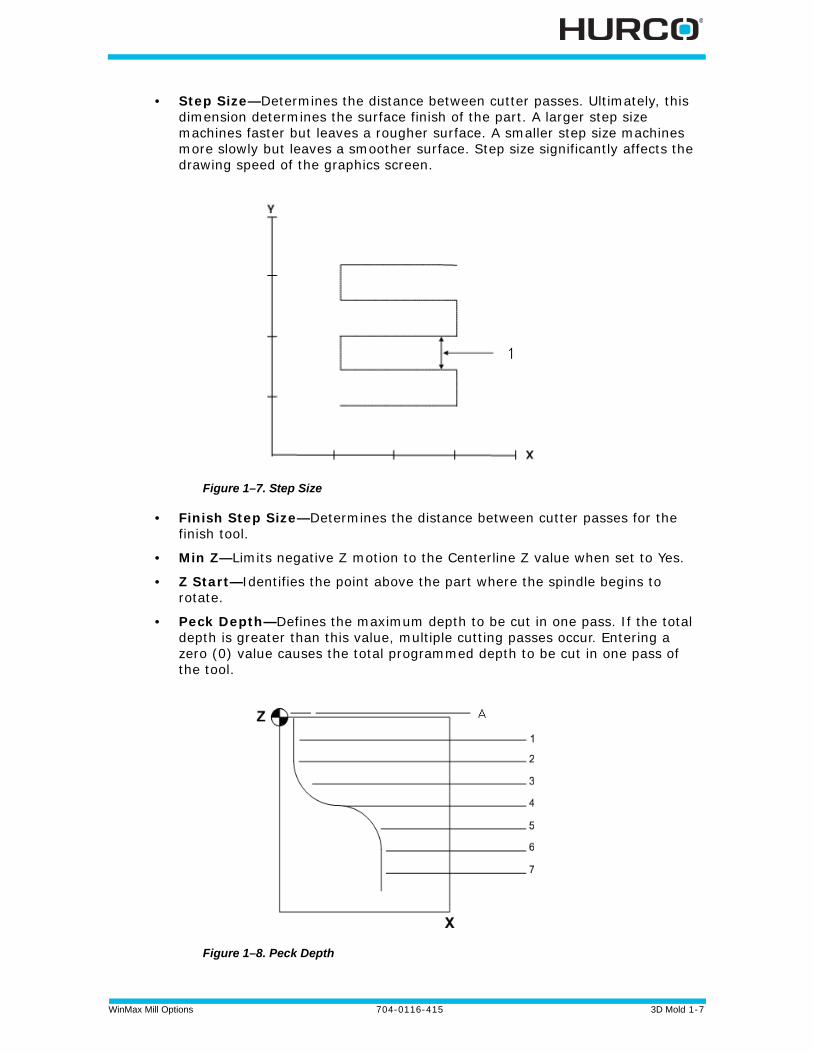
• Step Size—Determines the distance between cutter passes. Ultimately, this dimension determines the surface finish of the part. A larger step size machines faster but leaves a rougher surface. A smaller step size machines more slowly but leaves a smoother surface. Step size significantly affects the drawing speed of the graphics screen.
Figure 1–7. Step Size
• Finish Step Size—Determines the distance between cutter passes for the finish tool.
• Min Z—Limits negative Z motion to the Centerline Z value when set to Yes.
• Z Start—Identifies the point above the part where the spindle begins to rotate.
• Peck Depth—Defines the maximum depth to be cut in one pass. If the total depth is greater than this value, multiple cutting passes occur. Entering a zero (0) value causes the total programmed depth to be cut in one pass of the tool.
Figure 1–8. Peck Depth
1 - 8 3D Mold 704-0116-415 WinMax Mill Options
• Plunge Feed—Identifies the rate at which the tool initially enters the part.
• Mill Feed—Identifies the X-Y feedrate. The value initially displayed has been calculated by the control and can be retained or changed to a different value.
• Speed (RPM)—Identifies the spindle speed for the tool, calculated in Tool Setup. Entering a value here overrides the Tool Setup value for this data block.
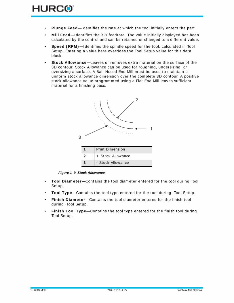
• Stock Allowance—Leaves or removes extra material on the surface of the 3D contour. Stock Allowance can be used for roughing, undersizing, or oversizing a surface. A Ball-Nosed End Mill must be used to maintain a uniform stock allowance dimension over the complete 3D contour. A positive stock allowance value programmed using a Flat End Mill leaves sufficient material for a finishing pass.
Figure 1–9. Stock Allowance
• Tool Diameter—Contains the tool diameter entered for the tool during Tool Setup.
• Tool Type—Contains the tool type entered for the tool during Tool Setup.
• Finish Diameter—Contains the tool diameter entered for the finish tool during Tool Setup.
• Finish Tool Type—Contains the tool type entered for the finish tool during Tool Setup.
1 Print Dimension
2 + Stock Allowance
3 - Stock Allowance
WinMax Mill Options 704-0116-415 3D Mold 1-9
3D Mold Contour
For Swept Surface programming, see Swept Surface in the Milling chapter of the Conversational Part Programming manual.
Used in conjunction with 3D Mold Parameters to mill a 3D Mold, program the part surfaces as a 2D profile in either the XY or XZ plane.
The Start Segment number is always 0. Use segments to program lines and arcs which create a contour. Repeat the 2D profile along a straight line (translate) or repeat it around a centerline (revolve) to produce the final 3D shape. The Contour End block marks the end of the programmed contour.
Select the Edit 3D Mold Parameters softkey to access the parameters screen. The Edit 3D Mold Parameters softkey is not available when the cursor is in either the Block or Segment field. When you select the Edit 3D Mold Parameters softkey, it changes to Edit 3D Mold Contour. This softkey is not available when the cursor is in the Block field.
The 3D Mold Start Segment fields are defined as follows:
• Block—Identifies the block number for the 3D Mold data block. The system determines the number by the position of this data block in the program.
• Segment—Identifies the segment number for this operation.
• X Start and Y Start or X Start and Z Start— Identify the starting location for the X and Y or X and Z coordinates. The X and Y or X and Z coordinates are carried forward to the next Segment.
Continue programming the contour by using the Page Down key or by selecting the Next Segment softkey.
Line, Arc, and Blend Arc softkey choices appear.
WinMax allows you to paste a contour into a 3D Mold Block on the Program Review screen. This allows you to use the same segments for a Mill Contour Block and a 3D Mold Block without entering each segment twice.
• To copy a contour, select the contour that you wish to copy on the Program Review Screen and use the MULTIPLE BLOCK FUNCTIONS softkey to access the COPY softkey.
• To paste a contour, select the 3D Mold Block that you wish to paste the contour into on the Program Review screen and use the MULTIPLE BLOCK FUNCTIONS softkey to access the PASTE softkey.
1 - 10 3D Mold 704-0116-415 WinMax Mill Options
3D Mold Line
For Swept Surface programming, see Swept Surface in the Milling chapter of the Conversational Part Programming manual.
Some 3D Mold Line fields are automatically calculated with the Auto-Calc feature.
The 3D Mold Line fields are defined as follows:
• Block—Identifies the block number for the 3D Mold data block. The system determines the number by the position of this data block in the program.
• Segment—Identifies the segment number for this operation. The system determines the number by the position of this segment in the program.
The following fields change depending on the type of contour selected:
• X End and Y End or X End and Z End—Identify the X End and Y End or X End and Z End coordinates. If two End coordinates are entered (X/Y or X/Z), the control automatically calculates the XY (or XZ) Length and the XY (or XZ) Angle fields. Use the Store Calculated Value softkey to retain the calculated value.
• XY Length or XZ Length—Identify the XY Length or XZ Length. If two End coordinates are entered (X End and Y End or X End and Z End), the control automatically calculates the XY Length and the XY Angle fields. Use the Store Calculated Value softkey to retain the calculated value.
• XY Angle or XZ Angle—Identify the XY Angle or XZ Angle or the angle of the line segment (from the start point to the end point), measured counterclockwise from the 3 o'clock position. If two End coordinates are entered (X End and Y End or X End and Z End), the control automatically calculates the XY Length and the XY Angle fields. Use the Store Calculated Value softkey to retain the calculated value.
• X Start and Y Start or X Start and Z Start—Define the starting points of this segment. The Start fields are carried forward from the previous segment's end points.
Continue programming the contour by using the PAGE DOWN key or by selecting the Next Segment softkey.
Line, Arc, and Blend Arc softkey choices appear.
WinMax Mill Options 704-0116-415 3D Mold 1-11
3D Mold Arc
For Swept Surface programming, see Swept Surface in the Milling chapter of the Conversational Part Programming manual.
Some 3D Mold Arc fields are automatically calculated with the Auto-Calc feature.
The 3D Mold Arc fields are defined as follows:
• Block—Identifies the block number for the 3D Mold data block. The system determines the number by the position of this data block in the program.
• Segment—Identifies the segment number for this operation. The system determines the number by the position of this segment in the program.
• Direction—Determines the direction of the arc from the start point (clockwise or counterclockwise).
The following fields change depending on the type of contour selected:
• X End and Y End or X End and Z End—Identify data coordinates (values for X End and Y End or X End and Z End) used in the automatic calculations. Use the Store Calculated Value softkey to retain the calculated value.
• X Center and Y Center or X Center and Z Center—Identify data coordinates (values for X Center and Y Center or X Center and Z Center) used in the automatic calculations. Use the Store Calculated Value softkey to retain the calculated value.
• Radius—Identifies the value for the Radius. The radius is used in the automatic calculations. Use the Store Calculated Value softkey to retain the calculated value.
• Sweep Angle—identifies the angular distance in degrees from the start point of the arc to the end point. The range is -360° to 360°.
• X Start and Y Start or X Start and Z Start—Define the starting points of this segment. The Start fields are carried forward from the previous segment's end points.
Continue programming the contour by using the PAGE DOWN key or by selecting the Next Segment softkey.
Line, Arc, and Blend Arc softkey choices appear.
1 - 12 3D Mold 704-0116-415 WinMax Mill Options
3D Mold Blend Arc
For Swept Surface programming, see Swept Surface in the Milling chapter of the Conversational Part Programming manual.
A blend arc is an arc that joins two other segments and is tangent to both. Use a blend arc to join two line segments, to join a line segment and an arc segment, or to join two arc segments. The segments to be joined must have a theoretical point of intersection.
If the only information known about an arc is its radius, it is easier to program it as a blend arc if the segments intersect.
The 3D Mold Blend Arc fields are defined as follows:
• Block—Identifies the block number for this operation. The system determines the number by the position of this data block in the program.
• Segment—Identifies the segment number for this operation. The system determines the number by the position of this segment in the contour.
• Radius—Identifies the radius of the arc.
• Direction—Identifies the direction of the arc from the start point (clockwise or counterclockwise).
The following fields change depending on the type of contour selected:
• X Start and Y Start or X Start and Z Start—Define the starting points of this segment. The Start fields are carried forward from the previous segment's end points.
• X End and Y End or X End and Z End—Identify the End coordinates.
• X Center and Y Center or X Center and Z Center—Identify the X Center and Y Center or X Center and Z Center coordinates used to define the circular path of the blend arc.
Continue programming the contour by using the PAGE DOWN key or by selecting the Next Segment softkey.
Line, Arc, and Blend Arc softkey choices appear.
WinMax Mill Options 704-0116-415 3D Mold 1-13
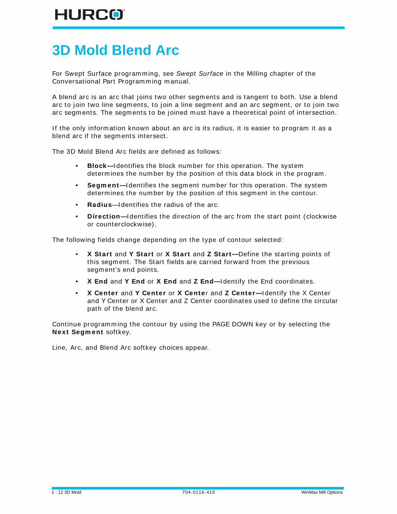
Roughing and Finishing Tools
In many applications, a Flat End Mill can be used for roughing, followed by a Ball-Nosed End Mill, which is required for cutting the finished surface.
Figure 1–10. Flat End Mill on a Contour
Figure 1–11. Ball-Nosed End Mill on a Contour
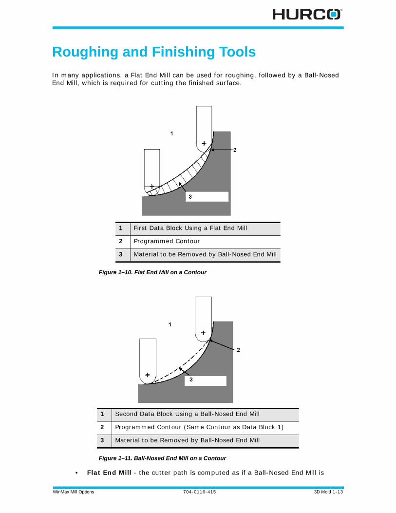
• Flat End Mill - the cutter path is computed as if a Ball-Nosed End Mill is
1 First Data Block Using a Flat End Mill
2 Programmed Contour
3 Material to be Removed by Ball-Nosed End Mill
1 Second Data Block Using a Ball-Nosed End Mill
2 Programmed Contour (Same Contour as Data Block 1)
3 Material to be Removed by Ball-Nosed End Mill
1 - 14 3D Mold 704-0116-415 WinMax Mill Options
used. This computation allows a Flat End Mill to be used for roughing without gouging the part, and in most cases leaves enough material to be removed for the finished surface using a Ball-Nosed End Mill.
Figure 1–12. Flat End Mill
1 Tool Calibrated on Tip
2 Tool Calculated as center of imaginary ball nose
3 Tool Zero
WinMax Mill Options 704-0116-415 3D Mold 1-15
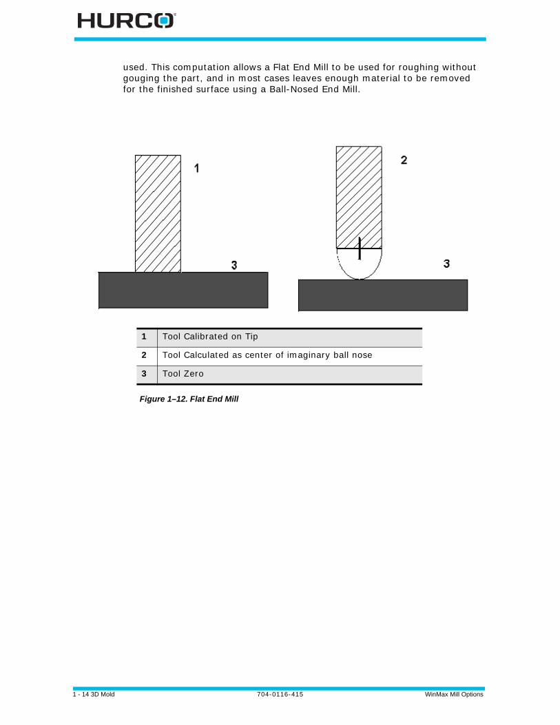
• Ball-Nosed End Mill - the system computes the compensated cutter path of the ball center:
Figure 1–13. Ball-Nosed End Mill
Special consideration must be taken when using a Finish Tool for a Mill Frame, Mill Circle or Mill Contour.
1 Tool Calibrated on Tip
2 Tool Calculated as center of ball nose
3 Tool Zero

1 - 16 3D Mold 704-0116-415 WinMax Mill Options
Roughing and Finishing Passes
The Flat End Mill tool path is calculated as a Ball-Nosed End Mill for the roughing pass.
The maximum additional material remaining on the overall 3D contour will not exceed the tool's radius.
Figure 1–14. Roughing and Finishing Passes
1 Roughing Contour Using Flat End Mill
2 Finishing Contour Using Ball-Nosed End Mill
3 Extra Material

WinMax Mill Options 704-0116-415 DXF Option 2-1
DXF OPTION
These topics are discussed in this section:
DXF Overview . . . . . . . . . . . . . . . . . . . . . . . . . . . . . . . . . . . . . . . . . . . . . 2 - 2
DXF Build Data Block . . . . . . . . . . . . . . . . . . . . . . . . . . . . . . . . . . . . . . . . 2 - 3
DXF Parameters . . . . . . . . . . . . . . . . . . . . . . . . . . . . . . . . . . . . . . . . . . . . 2 - 5
Edit Drawing . . . . . . . . . . . . . . . . . . . . . . . . . . . . . . . . . . . . . . . . . . . . . . 2 - 6
DXF Layers . . . . . . . . . . . . . . . . . . . . . . . . . . . . . . . . . . . . . . . . . . . . . . . 2 - 9
2 - 2 DXF Option 704-0116-415 WinMax Mill Options
DXF Overview
WinMax DXF offers greater flexibility, improved compatibility with AutoCad®, and the ability to save DXF changes directly to file (avoiding the need to send DXF files back to the CAD system for editing). The DXF file translation software is compatible with DXF files generated with Autocad version 12 and earlier.
DXF files are loaded directly into WinMax as follows:
1. Press the AUXILIARY console button.
2. Select the DXF icon on the Auxiliary screen.
3. Find the DXF file on the Load DXF File screen, and select it to highlight.
4. Select the LOAD F1 softkey.
The DXF program blocks are displayed in the Program Review Screen. On single-screen machines, use F+Draw (console key) to display the DXF drawing.
On dual-screen machines, the DXF drawing is displayed on the graphics screen. After building the data blocks, the part can be viewed in Solid or Toolpath graphics using the Draw console key. Switch the screen back to the DXF drawing using F + Draw (console keys). You can switch the screen back to the previously drawn graphic (without causing it to be redrawn) with the Draw console key. To redraw the graphic, select the Draw console key a second time (or access the DRAW OPTIONS F1 softkey).
DXF units of measurement (INCH or MM) match global WinMax units. When a data block is built from a CAD drawing, the data block adopts the unit displayed on the WinMax status bar. In Build DB, changing the WinMax unit will result in a different sized element, for example, a segment that is 3 inches or 3 mm in length.
Here are the softkeys on the DXF screen:
• Parameters—see DXF Parameters, on page 2 - 5.
• Build DB—see DXF Build Data Block, on page 2 - 3.
• Zoom Window—see Zoom Window, on page 2 - 5.
• Edit Drawing—see Edit Drawing, on page 2 - 6.
• Layers—see DXF Layers, on page 2 - 9.
• Save DXF—saves the DXF file.
• Part Programming—goes to the active part program.
• Quit CAD—exits the DXF CAD option.
The Part Programming softkey or icon toggles back to Part Programming without closing the DXF file. You may return to DXF at any time by selecting the DXF icon.
The DXF Editor is functional in Conversational programs only. If the DXF Editor is started when the current active program is NC, a prompt asks if you want to start a new conversational part program. Answer Yes to create a new Conversational part program.
WinMax Mill Options 704-0116-415 DXF Option 2-3
DXF Build Data Block
The Build DB softkey accesses the automatic data block building features. The system creates milling, holes, position, or pattern locations data blocks.
Milling - the Milling operation softkeys perform these functions in Lines/Arcs, Circles, Frame, 3D Mold, or Ellipse data blocks:
• Accept—loads the entity into the data block.
• Zoom Window—refer to Zoom Window, on page 2 - 5.
• Edit Drawing—refer to Edit Drawing, on page 2 - 6.
• Reverse—reverses the contour direction.
• AutoChain—defines contours by autochaining individual segments together.
• Default Radius—inserts the value of the default radius set in the Frame screen’s Corner Radius field.
• Exit/Cancel—cancels the operation and returns to the previous screen.
If you are using AutoCAD 14, set the registers to generate Polylines and Ellipses so they are saved as pline entity types and not splines.
Holes - Holes data blocks are built using the Hole Location Method (F1) or the Hole Pattern Method (F2):
• Use Hole Location Method—builds Holes Locations blocks from selected points on the drawing.
• Use Hole Pattern Method—builds Holes Pattern blocks from selected points on the drawing.
For either softkey, select holes on the drawing with one of three methods:
• Select individual holes on the touchscreen.
• Choose the Window Select softkey and drag across an area of the screen to select a group of holes.
• Use the Intersect softkey to select two intersecting lines. The point of intersection becomes the center of the hole.
Select the Accept softkey to create the data blocks.
These are the softkeys in the Holes menu:
• Accept—loads the entity into the data block.
• Zoom Window— refer to Zoom Window, on page 2 - 5.
• Edit Drawing—refer to Edit Drawing, on page 2 - 6.
• Window Select—selects a group of holes on the drawing.
• Intersect—draws a hole at the intersection of two selected lines and represents the center with a highlighted plus (+).
• Default Order—orders the holes as they were selected in the Auto CAD

2 - 4 DXF Option 704-0116-415 WinMax Mill Options
drawing.
• Exit/Cancel—cancels the operation and returns to the previous screen.
Position - creates a Position data block from the DXF drawing. These are the softkeys on the Position menu:
• Accept—loads the entity into the data block.
• Zoom Window—refer to Zoom Window, on page 2 - 5.
• Edit Drawing—refer to Edit Drawing, on page 2 - 6.
• Window Select—selects a group of holes on the drawing.
• Intersect—draws a hole at the intersection of two selected lines and represents the center with a highlighted plus (+).
• Default Order—orders the holes as they were drawn in the original AutoCAD drawing.
• Exit/Cancel—cancels the operation and returns to the previous screen.
Pattern Locations—builds a Pattern data block. To use, select the softkey and then select points on the drawing to serve as pattern locations, using one of the following methods:
• Select individual holes on the touchscreen.
• Choose the Window Select softkey and drag across an area of the screen to select a group of holes.
• Use the Intersect softkey to select two intersecting lines. The point of intersection becomes the center of the hole.
Select the Accept softkey to create an empty Pattern Locations data block. Additional data can then be added either manually or from the DXF drawing.
These are the softkeys on the Pattern Locations menu:
• Accept—loads the entity into the data block.
• Zoom Window— refer to Zoom Window, on page 2 - 5.
• Edit Drawing—refer to Edit Drawing, on page 2 - 6.
• Window Select—selects a group of holes on the drawing.
• Intersect—specifies a pattern location at the intersection of two selected lines.
• Default Order—orders the holes as they were selected in the Auto CAD drawing.
• Exit/Cancel—cancels the operation and returns to the previous screen.
WinMax Mill Options 704-0116-415 DXF Option 2-5
DXF Parameters
These parameters link contour segments, define part zero within the drawing, and set the radius for frame corners.
Use the Move Zero and Select Value softkeys to change the location of part zero. The Exit softkey returns to the DXF softkeys.
The fields on the DXF Parameters dialog box are defined as follows:
• Endpoint Tolerance—determines when the endpoints of segments are close enough to be considered equal (or coincident).
• Part X Offset and Part Y Offset—define part zero within the drawing. All dimensions are calculated from this point. The part zero symbol is a circle with crosshairs. To change this location manually, move the cursor to the field for Part X or Y Offset and enter the X or Y Offset values. To change this location graphically and automatically, use the Move Zero softkey.
• Frame Radius—sets a default corner radius to be used in Build DB. If the corners of a frame do not have the same radius, the user is prompted to either select a corner radius on the drawing or use the default value entered in this field for the radius.
• Hole Diameter—determines the default diameter for a hole.
Use the touchscreen to turn the remaining DXF Parameter fields on or off:
• Display Geometry—shows selected lines on the graphic display in a color other than black, illustrating which elements have been selected. Colors can be changed with the Choose Colors softkey on the Parameters screen.
• Autochain Contours—allows autochaining to be turned off so that a contour may be created by individually selected segments into a chained contour. By default, segments are automatically chained to create contours.
• Select Holes by Diameter—selects holes with the diameter specified in the Hole Diameter field (defined above) when the WINDOW SELECT softkey is used. This selection allows you to order the hole selection by size, which optimizes tool changes.
Zoom Window
Use the Zoom Window softkey to enlarge an area of the drawing or zoom out to see a full view. Use the pointer to touch an area on the screen and drag across the screen to enlarge an area of the drawing. When an area is enlarged, use the following softkeys:
• Zoom Out—pulls back from the drawing incrementally to the previous magnification level without re-centering the part in the drawing.
• Fit to View—gives a full scale of the drawing with the part in the drawing auto-centered.
• Pan—relocates the center of the drawing on the Graphic display.
• Exit—returns to the previous menu.
2 - 6 DXF Option 704-0116-415 WinMax Mill Options
Edit Drawing
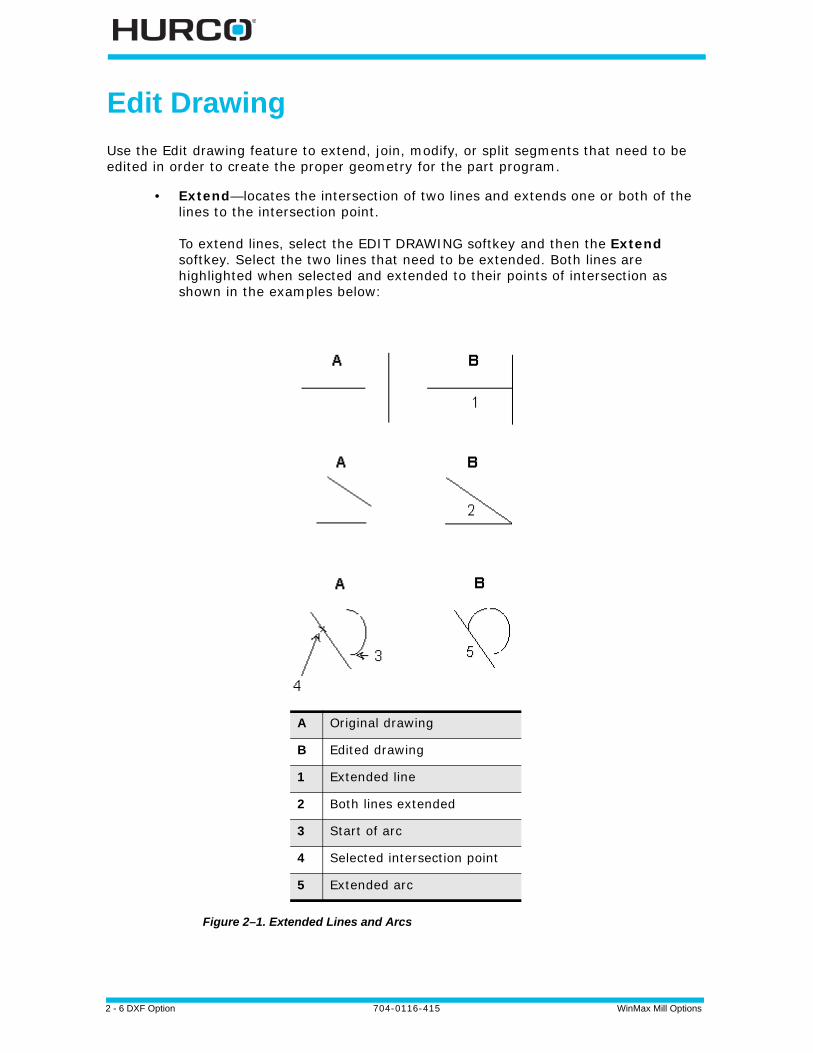
Use the Edit drawing feature to extend, join, modify, or split segments that need to be edited in order to create the proper geometry for the part program.
• Extend—locates the intersection of two lines and extends one or both of the lines to the intersection point.
To extend lines, select the EDIT DRAWING softkey and then the Extend softkey. Select the two lines that need to be extended. Both lines are highlighted when selected and extended to their points of intersection as shown in the examples below:
Figure 2–1. Extended Lines and Arcs
A Original drawing
B Edited drawing
1 Extended line
2 Both lines extended
3 Start of arc
4 Selected intersection point
5 Extended arc
WinMax Mill Options 704-0116-415 DXF Option 2-7
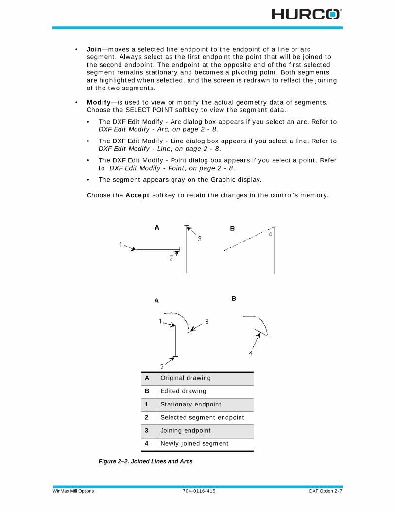
• Join—moves a selected line endpoint to the endpoint of a line or arc segment. Always select as the first endpoint the point that will be joined to the second endpoint. The endpoint at the opposite end of the first selected segment remains stationary and becomes a pivoting point. Both segments are highlighted when selected, and the screen is redrawn to reflect the joining of the two segments.
• Modify—is used to view or modify the actual geometry data of segments. Choose the SELECT POINT softkey to view the segment data.
• The DXF Edit Modify - Arc dialog box appears if you select an arc. Refer to DXF Edit Modify - Arc, on page 2 - 8.
• The DXF Edit Modify - Line dialog box appears if you select a line. Refer to DXF Edit Modify - Line, on page 2 - 8.
• The DXF Edit Modify - Point dialog box appears if you select a point. Refer to DXF Edit Modify - Point, on page 2 - 8.
• The segment appears gray on the Graphic display.
Choose the Accept softkey to retain the changes in the control's memory.
Figure 2–2. Joined Lines and Arcs
A Original drawing
B Edited drawing
1 Stationary endpoint
2 Selected segment endpoint
3 Joining endpoint
4 Newly joined segment
2 - 8 DXF Option 704-0116-415 WinMax Mill Options
• Split—use to divide segments for selection, de-selection, and chaining. Segments may be split at midpoint or any point of intersection with other segments.
To split a segment, first select the segment and then select the point where the segment will be divided. When a segment is selected for splitting, the midpoint and all intersection points with the other segments are indicated with crosshair markers. Follow the directions in the Prompt display.
• Delete—deletes a programmed endpoint.
• Trim—trims a selected segment.
• Explode PCurve—shows an exploded view of a selected PolyCurve. If you are using Auto CAD 14, set the registers to generate Polylines and Ellipses so they are saved as pline entity types and not splines.
• Exit/Cancel—return to the Main DXF menu.
DXF Edit Modify - Arc
The DXF Edit Modify - Arc dialog window contains these fields:
• Start Angle—defines the starting point of the angle.
• Sweep Angle—defines the total number of degrees in the arc to be cut. This number can be greater than 350.
• Direction—identifies the direction of the arc from the start point.
• Radius—identifies the radius of the arc.
• Center X and Center Y—identify the X and Y coordinates for the center point of the arc.
DXF Edit Modify - Line
The DXF Edit Modify - Line dialog window contains these fields:
• Endpoint1 X and Endpoint1 Y—define the first endpoints for the X and Y coordinates.
• Endpoint2 X and Endpoint2 Y—define the second endpoints for the X and Y coordinates.
• Length—identifies the line length.
• XY Angle—identifies the angle of the XY coordinate.
DXF Edit Modify - Point
The DXF Edit Modify - Point dialog window contains these fields:
• X Value—identifies the X location for the selected point.
• Y Value—identifies the Y location for the selected point.

WinMax Mill Options 704-0116-415 DXF Option 2-9
DXF Layers
Many DXF drawings use layers - an electronic method of representing transparent acetate overlays used in hand-drawn drafting work.
• Select Layer—toggles the highlighted layer on and off.
• All On—turns on all of the layers.
• All Off—turns off all of the layers.
• Exit—return to the Main DXF menu.

2 - 10 DXF Option 704-0116-415 WinMax Mill Options
WinMax Mill Options 704-0116-415 Helical Plunge Option 3-1
HELICAL PLUNGE OPTION
The Helical Plunge programming option provides helical plunge as an alternative machining strategy. Helical plunge and straight plunges can be used separately for roughing and finishing phases, or they can be used together for the same operation. For example, you can rough with a helical plunge and finish with a straight plunge.
In the Helical Plunge option, the tool rotates around the cut and moves down the Z-axis. The cutting tool is continuously cutting deeper and enters and exists the machined part only once.
To use Helical Plunge, set the Mill or Finish Plunge Type in Milling Parameters to Helix.
Helical Plunge Milling Parameter Fields . . . . . . . . . . . . . . . . . . . . . . . . . . . . 3 - 2
Helical Plunge (Inside/Outside) for Mill Frames, Mill Circles and Ellipses . . . . . 3 - 4
Helical Plunge with UltiPocket. . . . . . . . . . . . . . . . . . . . . . . . . . . . . . . . . . . 3 - 4
Helical Plunge with Operator Specified Location . . . . . . . . . . . . . . . . . . . . . . 3 - 4
Helical Plunge in the Center of a Pocket. . . . . . . . . . . . . . . . . . . . . . . . . . . . 3 - 4
Helical Plunge with Outward Pocketing . . . . . . . . . . . . . . . . . . . . . . . . . . . . 3 - 5
Helical Plunge of Mill Frame Inside with No Pecking and Blend Offset . . . . . . . 3 - 5
Helical Plunging of Mill Frame Inside with Pecking and Straight Plunge Finish Pass and Blend Offset. . . . . . . . . . . . . . . . . . . . . . . . . . . . . . . . . . . . . . . . . . . . . . . 3 - 6
Helical Plunge with Lines and Arcs . . . . . . . . . . . . . . . . . . . . . . . . . . . . . . . 3 - 8
Helical Plunge with 3-D Part Programming Option. . . . . . . . . . . . . . . . . . . . . 3 - 8
• Helical Plunge uses the feedrate programmed by the operator on the mill circle, mill frame, ellipse, or mill contour start screens.
• Pattern blocks can be used with helical plunging. A scaled-up or scaled-down pattern will not affect the diameter of the helix plunge. When using a mirror image pattern, the helical plunge will be in the negative Z direction.
• Helical Plunge for rotary mill frames, mill circles, and mill contours is similar to helical plunging for non-rotary mill frames, mill circles, and mill contours.

3 - 2 Helical Plunge Option 704-0116-415 WinMax Mill Options
Helical Plunge Milling Parameter Fields
On the Milling Parameters screen, choose the Mill Plunge Type as Helix. If the Helical Plunge option is enabled, the fields specifying the plunging parameters appear. If the fields do not appear, the Helical Plunge option has not been installed on the control. Call Hurco or a Hurco distributor to purchase the option.
• Mill Plunge Type—specifies the plunging strategy to use for the milling pass. Choose Straight or Helix. The default setting is Straight.
• Mill Plunge Ramp Slope—defines the slope of the helical ramp for the milling tool. The range is 1° to 90°. Choosing 90° will result in a Straight Plunge. The default value is 10°.
• Mill Plunge Helix Radius—used for specifying the Helical Plunge radius as a percentage of the tool diameter. The range is from 0% to 100%. Choosing 0% results in a Straight Plunge. If a value of 50% or less is chosen, it will prevent a post (a thin cylinder of material formed after helical plunging) from being formed by the Helical Plunge. The default setting is 25%.
• Finish Plunge Type—specifies the plunging strategy to use for the finish phase. Choose Straight or Helix. The default setting is Straight.
• Finish Plunge Ramp Slope—defines the slope of the Helical Ramp for the finishing tool. Range is 1° to 90°. Choosing 90° will result in a Straight Plunge. The default setting is 25°.
• Finish Plunge Helix Radius—defines the value of the Helical Plunge radius as a percentage of the diameter of the finishing tool. The range is 0% to 100%. If a value of 50% or less is chosen, it will prevent a post from being formed by the Helical Plunge. The default setting is 25%.
• Operator Specify Pocket Start—if Yes, the pocket start location fields will appear on pocket boundary screens, when Pocket Type Inward is selected. The default setting is No. The value of Pocket Plunge Near Center is ignored.
• Pocket Plunge Near Center—if Yes, UltiPocket will attempt to perform a plunge at the approximate center of the pocket and then move to the start point of the pocket. If the software detects an interference with plunging in the center, the plunge will be made at the start of the tool path. The default setting is No.
• Allow Plunge Outside Pocket—if Yes, UltiPocket will plunge outside the pocket, moving through the open side of the pocket boundary. May be used with open contours only; cannot be applied to frames, circles, or ellipses because they cannot be programmed with open contours.
Helical Plunge Milling Parameter fields are available only in Conversational Programming.
The Pocket Plunge Near Center parameter may be used with frames, circles, ellipses, and contours with Pocket Type Inward, and contours with Pocket Type Outward.
Frames, circles, and ellipses with Pocket Type Outward automatically attempt to plunge to the center.
WinMax Mill Options 704-0116-415 Helical Plunge Option 3-3
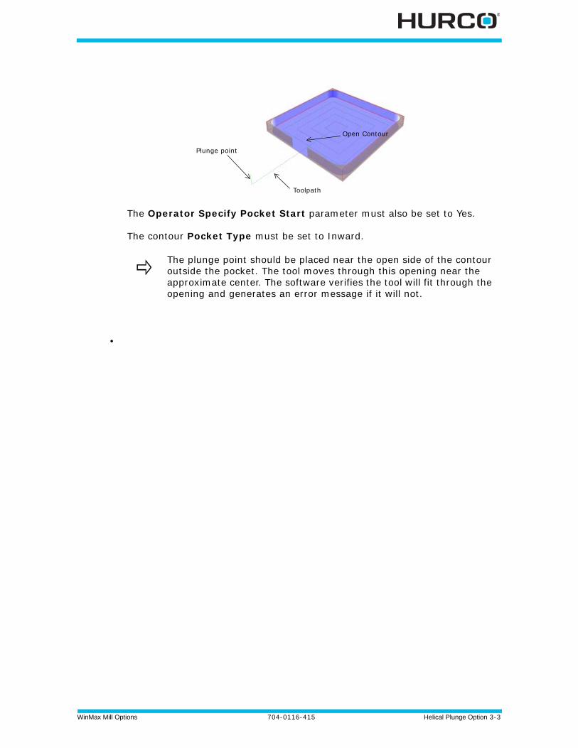
The Operator Specify Pocket Start parameter must also be set to Yes.
The contour Pocket Type must be set to Inward.
•
The plunge point should be placed near the open side of the contour outside the pocket. The tool moves through this opening near the approximate center. The software verifies the tool will fit through the opening and generates an error message if it will not.
Plunge point
Toolpath
Open Contour
3 - 4 Helical Plunge Option 704-0116-415 WinMax Mill Options
Helical Plunge (Inside/Outside) for Mill Frames, Mill Circles and Ellipses
Helical Plunge is similar for milling the inside or outside of mill frames, circles, and ellipses (with or without blend-in moves). The center location of the helical plunge is the same as a straight plunge. The direction of the helical plunge (clockwise, CW, or counter clockwise, CCW) will be determined by the tool spin direction (CW or CCW) and the milling direction (climb or conventional). If Blend Offset is used, the helical plunge will be centered about the plunge point of the Blend Offset.
The helical plunge direction that provides a smooth transition to the tool path will be chosen. Helical plunge is not allowed when Milling Type On is selected.
Helical Plunge with UltiPocket
The Helical Plunge option is used with the UltiPocket option to define the plunging location when inward pocketing. The operator can specify the pocket plunge location using the Operator Specify Pocket Start function, or start the pocket plunge near the center by using the Inward Pocket Plunge Near Center function. See the UltiPocket Option chapter for more information on using the Helical Plunge option with UltiPocket.
When both the Operator Specify Pocket Start and the Inward Pocket Plunge Near Center are set to No, the plunge locations are used that would have been used without the Helical Plunge option.
Helical Plunge with Operator Specified Location
When the operator specifies the plunge point, all of the helix plunge moves will occur at that location, even for the pocket boundary.
Helical Plunge in the Center of a Pocket
When the Inward Pocket Plunge Near Center field value is Yes (Operator Specify Pocket Start value must be No), a plunge point near the center of the pocket will be chosen. Islands near the center will impact upon the plunge point’s location.
An error message appears if the plunge point specified would violate the programmed part surface.
When machining a part with a lot of webbing (many small pockets separated by walls), it may be desirable to disable helical plunging.
WinMax Mill Options 704-0116-415 Helical Plunge Option 3-5
Helical Plunge with Outward Pocketing
Helical plunging occurs near the center of the pocket when used with Outward Pocketing, and only one plunge location is needed. The Operator Specify Pocket Start and the Inward Pocket Plunge Near Center fields have no effect on Helical Plunge with Outward Pocketing.
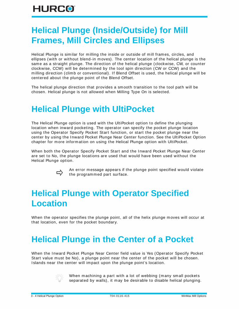
Helical Plunge of Mill Frame Inside with No Pecking and Blend Offset
The tool will helical plunge to the Z Bottom level and then perform the normal blend-in move. The direction of the helical plunge arc will smoothly transition to the blend-in arc. For instance, if the blend-in arc is CCW, the direction of the helical plunge will be CW. The following isometric views are created by setting the Draw Plunge Moves graphics parameter field to Yes.
The graphics show the finish pass only if a finish tool is specified in the frame block, and do not show individual peck levels.
Figure 3–1. Helical Plunge with No Pecking and Blend Offset (Isometric View)
This graphical representation is only for informational purposes and cannot be viewed with WinMax.
3 - 6 Helical Plunge Option 704-0116-415 WinMax Mill Options
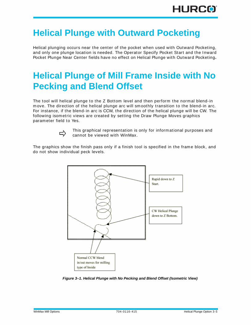
Helical Plunging of Mill Frame Inside with Pecking and Straight Plunge Finish Pass and Blend Offset
The following example is a Mill Frame Block Type with Inside Milling Type. The finish tool specified and the peck depth is set to 0.6 inches.
First Peck - The tool helical plunges down to the -first peck depth, then mills another full circle to ensure that all material down to the first peck is removed. After the full circle is completed, a 180o blend in arc is performed. The direction of the helical plunge will always be in the opposite direction of the blend-in arc.
Figure 3–2. First Peck (Isometric View)
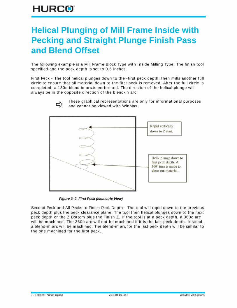
Second Peck and All Pecks to Finish Peck Depth - The tool will rapid down to the previous peck depth plus the peck clearance plane. The tool then helical plunges down to the next peck depth or the Z Bottom plus the Finish Z. If the tool is at a peck depth, a 360o arc will be machined. The 360o arc will not be machined if it is the last peck depth. Instead, a blend-in arc will be machined. The blend-in arc for the last peck depth will be similar to the one machined for the first peck.
These graphical representations are only for informational purposes and cannot be viewed with WinMax.
WinMax Mill Options 704-0116-415 Helical Plunge Option 3-7
Figure 3–3. Second Peck (Isometric View)
Finish Pass - The tool will rapid down to the Z Start and plunge feed down to the Z Bottom. A blend-in move is performed before milling the frame contour.
Figure 3–4. Finish Pass (Isometric View)
When helical plunge is used for roughing passes, a large amount of material is removed around the point of entry. Therefore, using helical plunging for the finish passes is probably not necessary.
If the finish tool is larger than the roughing tool, helical plunges should also be performed for the finish pass. If a post was created by the roughing tool (the Helix plunge radius was greater than 50 percent) the finish tool may be cutting into the post.
3 - 8 Helical Plunge Option 704-0116-415 WinMax Mill Options
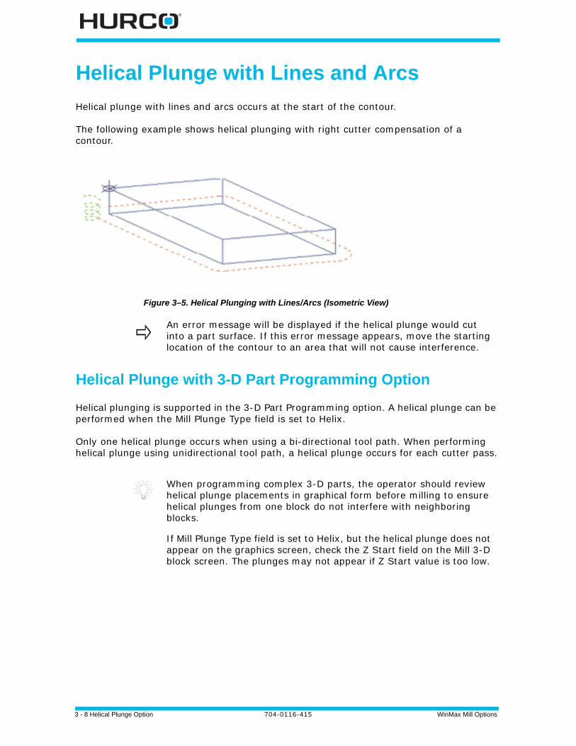
Helical Plunge with Lines and Arcs
Helical plunge with lines and arcs occurs at the start of the contour.
The following example shows helical plunging with right cutter compensation of a contour.
Figure 3–5. Helical Plunging with Lines/Arcs (Isometric View)
Helical Plunge with 3-D Part Programming Option
Helical plunging is supported in the 3-D Part Programming option. A helical plunge can be performed when the Mill Plunge Type field is set to Helix.
Only one helical plunge occurs when using a bi-directional tool path. When performing helical plunge using unidirectional tool path, a helical plunge occurs for each cutter pass.
An error message will be displayed if the helical plunge would cut into a part surface. If this error message appears, move the starting location of the contour to an area that will not cause interference.
When programming complex 3-D parts, the operator should review helical plunge placements in graphical form before milling to ensure helical plunges from one block do not interfere with neighboring blocks.
If Mill Plunge Type field is set to Helix, but the helical plunge does not appear on the graphics screen, check the Z Start field on the Mill 3-D block screen. The plunges may not appear if Z Start value is too low.

WinMax Mill Options 704-0116-415 Insert Pockets 4-1
INSERT POCKETS
Cutter insert manufacturers use the Insert Pockets milling routines to mill pockets in triangular, diamond, and hexagon shapes. These routines are sold as a WinMax option and can be defined in one program data block.
To access the Insert Pockets features, select the Milling softkey in a New Block screen, then Select the More softkey. If the option is installed the next screen will have a Special softkey. Select that softkey to display the following screen:
Figure 4–1. Insert Pockets Softkeys
Choose Triangle, Diamond 1 Face, Diamond 2 Faces, or Hexagon milling. These data blocks are described in the sections that follow:
Mill Triangle Data Block, on page 4 - 2
Mill Diamond Data Block, on page 4 - 4
Mill Hexagon Data Block, on page 4 - 7
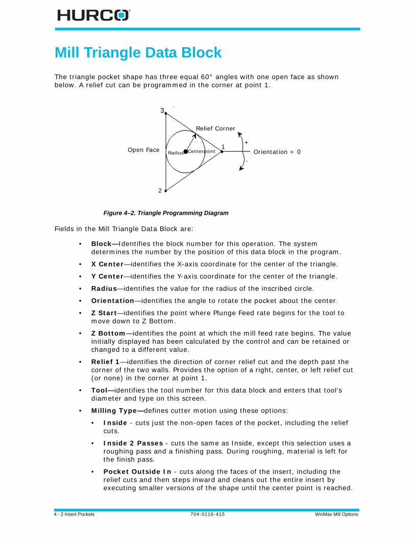
4 - 2 Insert Pockets 704-0116-415 WinMax Mill Options
Mill Triangle Data Block
The triangle pocket shape has three equal 60° angles with one open face as shown below. A relief cut can be programmed in the corner at point 1.
Figure 4–2. Triangle Programming Diagram
Fields in the Mill Triangle Data Block are:
• Block—Identifies the block number for this operation. The system determines the number by the position of this data block in the program.
• X Center—identifies the X-axis coordinate for the center of the triangle.
• Y Center—identifies the Y-axis coordinate for the center of the triangle.
• Radius—identifies the value for the radius of the inscribed circle.
• Orientation—identifies the angle to rotate the pocket about the center.
• Z Start—identifies the point where Plunge Feed rate begins for the tool to move down to Z Bottom.
• Z Bottom—identifies the point at which the mill feed rate begins. The value initially displayed has been calculated by the control and can be retained or changed to a different value.
• Relief 1—identifies the direction of corner relief cut and the depth past the corner of the two walls. Provides the option of a right, center, or left relief cut (or none) in the corner at point 1.
• Tool—identifies the tool number for this data block and enters that tool's diameter and type on this screen.
• Milling Type—defines cutter motion using these options:
• Inside - cuts just the non-open faces of the pocket, including the relief cuts.
• Inside 2 Passes - cuts the same as Inside, except this selection uses a roughing pass and a finishing pass. During roughing, material is left for the finish pass.
• Pocket Outside In - cuts along the faces of the insert, including the relief cuts and then steps inward and cleans out the entire insert by executing smaller versions of the shape until the center point is reached.
Open Face Orientation = 0
Relief Corner
Radius Centerpoint
3
2
1

WinMax Mill Options 704-0116-415 Insert Pockets 4-3
• Pocket 2 Passes Outside In - cuts in the same manner as Pocket Outside In, except this selection uses a roughing and a finishing pass.
• Pocket Inside Out - plunges tool at X-Y center of the insert and cuts outward, executing larger versions of the shape until the faces and relief cuts are milled.
• Pocket 2 Passes Inside Out - cuts the same as Pocket Inside Out, except this selection uses a roughing and a finishing pass.
• Mill Feed—defines the X-Y feedrate.
• Speed (RPM)—identifies the speed at which the spindle rotates to machine the part.
• Peck Depth—Defines the maximum depth to be cut in one pass. If the total depth is greater than this value, multiple cutting passes occur. Entering a zero (0) value causes the total programmed depth to be cut in one pass of the tool.
• Plunge Feed—Defines the feed rate for the tool moving from Z Start to Z Bottom. Also used when plunging down in Z between peck depth passes.
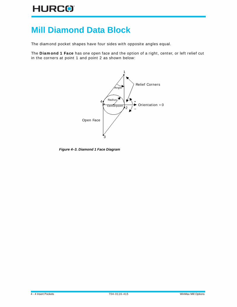
4 - 4 Insert Pockets 704-0116-415 WinMax Mill Options
Mill Diamond Data Block
The diamond pocket shapes have four sides with opposite angles equal.
The Diamond 1 Face has one open face and the option of a right, center, or left relief cut in the corners at point 1 and point 2 as shown below:
Figure 4–3. Diamond 1 Face Diagram
Open Face
Orientation =0
Relief CornersAngle
Radius
1
Centerpoint 2
3
4
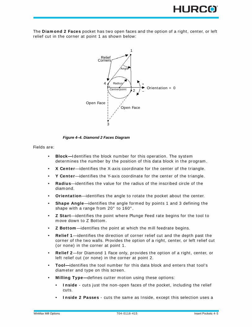
WinMax Mill Options 704-0116-415 Insert Pockets 4-5
The Diamond 2 Faces pocket has two open faces and the option of a right, center, or left relief cut in the corner at point 1 as shown below:
Figure 4–4. Diamond 2 Faces Diagram
Fields are:
• Block—Identifies the block number for this operation. The system determines the number by the position of this data block in the program.
• X Center—identifies the X-axis coordinate for the center of the triangle.
• Y Center—identifies the Y-axis coordinate for the center of the triangle.
• Radius—identifies the value for the radius of the inscribed circle of the diamond.
• Orientation—identifies the angle to rotate the pocket about the center.
• Shape Angle—identifies the angle formed by points 1 and 3 defining the shape with a range from 20° to 160°.
• Z Start—identifies the point where Plunge Feed rate begins for the tool to move down to Z Bottom.
• Z Bottom—identifies the point at which the mill feedrate begins.
• Relief 1—identifies the direction of corner relief cut and the depth past the corner of the two walls. Provides the option of a right, center, or left relief cut (or none) in the corner at point 1.
• Relief 2—for Diamond 1 Face only, provides the option of a right, center, or left relief cut (or none) in the corner at point 2.
• Tool—identifies the tool number for this data block and enters that tool's diameter and type on this screen.
• Milling Type—defines cutter motion using these options:
• Inside - cuts just the non-open faces of the pocket, including the relief cuts.
• Inside 2 Passes - cuts the same as Inside, except this selection uses a
Open FaceOpen Face
Orientation = 0
ReliefCorners
Angle
Radius
Centerpoint
1
2
3
4

4 - 6 Insert Pockets 704-0116-415 WinMax Mill Options
roughing pass and a finishing pass. During roughing, material is left for the finish pass.
• Pocket Outside In - cuts along the faces of the insert, including the relief cuts and then steps inward and cleans out the entire insert by executing smaller versions of the shape until the center point is reached.
• Pocket 2 Passes Outside In - cuts in the same manner as Pocket Outside In, except this selection uses a roughing and a finishing pass.
• Pocket Inside Out - plunges tool at X-Y center of the insert and cuts outward, executing larger versions of the shape until the faces and relief cuts are milled.
• Pocket 2 Passes Inside Out - cuts the same as Pocket Inside Out, except this selection uses a roughing and a finishing pass.
• Mill Feed—defines the X-Y feedrate.
• Speed (RPM)—identifies the speed at which the spindle rotates to machine the part.
• Peck Depth—Defines the maximum depth to be cut in one pass. If the total depth is greater than this value, multiple cutting passes occur. Entering a zero (0) value causes the total programmed depth to be cut in one pass of the tool.
• Plunge Feed—Defines the feed rate for the tool moving from Z Start to Z Bottom. Also used when plunging down in Z between peck depth passes.

WinMax Mill Options 704-0116-415 Insert Pockets 4-7
Mill Hexagon Data Block
This pocket shape has six sides and every other angle equal. In the diagram below, the shape has two open faces and the option of a relief cut in the corners at point 1, point 2, and point 3, and the option of a face relief distance between points 0 and 1 and points 3 and 4.
Figure 4–5. Hexagon Diagram
P-0 Point 0P-1 Point 1P-2 Point 2P-3 Point 3P-4 Point 4P-5 Point 5R-1 Relief 1R-2 Relief 2R-3 Relief 3
Orientation=0
Radius
ShapeAngleX and Y
Centerpoint
Tool path
Relief Distance
4 - 8 Insert Pockets 704-0116-415 WinMax Mill Options
Fields are:
• Block—Identifies the block number for this operation. The system determines the number by the position of this data block in the program.
• X Center—identifies the X-axis coordinate for the center of the triangle.
• Y Center—identifies the Y-axis coordinate for the center of the triangle.
• Radius—identifies the value for the radius of the inscribed circle.
• Orientation—identifies the angle to rotate the pocket about the center.
• Shape Angle—identifies the angle formed by points 1 and 3 defining the shape with a range from 20° to 160°.
• Z Start—identifies the point where Plunge Feed rate begins for the tool to move down to Z Bottom.
• Z Bottom—identifies the point at which the mill feedrate begins.
• Relief 1—identifies the direction of corner relief cut and the depth past the corner of the two walls. Provides the option of a right, center, or left relief cut (or none) in the corner at point 1, or face relief distance between points 0 and 1.
• Relief 2—provides the option of a right, center, or left relief cut (or none) in the corner at point 2.
• Relief 3—provides the option of a right, center, or left relief cut (or none) in the corner at point 3 or the option of a face relief distance between points 3 and 4.
• Tool—identifies the tool number for this data block and enters that tool's diameter and type on this screen.
• Milling Type—defines cutter motion using these options:
• Inside - cuts just the non-open faces of the pocket, including the relief cuts.
• Inside 2 Passes - cuts the same as Inside, except this selection uses a roughing pass and a finishing pass. During roughing, material is left for the finish pass.
• Pocket Outside In - cuts along the faces of the insert, including the relief cuts and then steps inward and cleans out the entire insert by executing smaller versions of the shape until the center point is reached.
• Pocket 2 Passes Outside In - cuts in the same manner as Pocket Outside In, except this selection uses a roughing and a finishing pass.
• Pocket Inside Out - plunges tool at X-Y center of the insert and cuts outward, executing larger versions of the shape until the faces and relief cuts are milled.
• Pocket 2 Passes Inside Out - cuts the same as Pocket Inside Out, except this selection uses a roughing and a finishing pass.
• Mill Feed—defines the X-Y feedrate.
• Speed (RPM)—identifies the speed at which the spindle rotates to machine the part.

WinMax Mill Options 704-0116-415 Insert Pockets 4-9
• Peck Depth—Defines the maximum depth to be cut in one pass. If the total depth is greater than this value, multiple cutting passes occur. Entering a zero (0) value causes the total programmed depth to be cut in one pass of the tool.
• Plunge Feed—Defines the feed rate for the tool moving from Z Start to Z Bottom. Also used when plunging down in Z between peck depth passes.

4 - 10 Insert Pockets 704-0116-415 WinMax Mill Options

WinMax Mill Options 704-0116-415 Rotary 5-1
ROTARY
These topics are discussed in this section:
Rotary Overview. . . . . . . . . . . . . . . . . . . . . . . . . . . . . . . . . . . . . . . . . . . . 5 - 2
Rotary Part Setup . . . . . . . . . . . . . . . . . . . . . . . . . . . . . . . . . . . . . . . . . . . 5 - 8
Rotary Part Programming . . . . . . . . . . . . . . . . . . . . . . . . . . . . . . . . . . . . . 5 - 10
Rotary A and Rotary A Tilt B Configuration . . . . . . . . . . . . . . . . . . . . . . . . . 5 - 14
Tilt A Rotary C Configuration . . . . . . . . . . . . . . . . . . . . . . . . . . . . . . . . . . . 5 - 20
Rotary B Configuration . . . . . . . . . . . . . . . . . . . . . . . . . . . . . . . . . . . . . . . 5 - 26
Tilt B Rotary C Configuration . . . . . . . . . . . . . . . . . . . . . . . . . . . . . . . . . . . 5 - 29
Universal Rotary Configuration . . . . . . . . . . . . . . . . . . . . . . . . . . . . . . . . . . 5 - 35
Calculating X- and Z-Axis Positions After a Tilt-Axis Move . . . . . . . . . . . . . . . 5 - 49
Example Programs . . . . . . . . . . . . . . . . . . . . . . . . . . . . . . . . . . . . . . . . . . 5 - 51
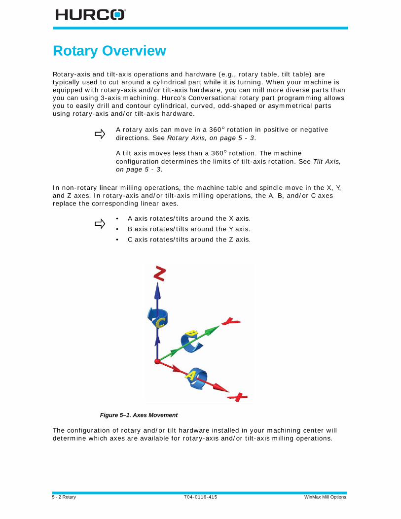
5 - 2 Rotary 704-0116-415 WinMax Mill Options
Rotary Overview
Rotary-axis and tilt-axis operations and hardware (e.g., rotary table, tilt table) are typically used to cut around a cylindrical part while it is turning. When your machine is equipped with rotary-axis and/or tilt-axis hardware, you can mill more diverse parts than you can using 3-axis machining. Hurco’s Conversational rotary part programming allows you to easily drill and contour cylindrical, curved, odd-shaped or asymmetrical parts using rotary-axis and/or tilt-axis hardware.
In non-rotary linear milling operations, the machine table and spindle move in the X, Y, and Z axes. In rotary-axis and/or tilt-axis milling operations, the A, B, and/or C axes replace the corresponding linear axes.
Figure 5–1. Axes Movement
The configuration of rotary and/or tilt hardware installed in your machining center will determine which axes are available for rotary-axis and/or tilt-axis milling operations.
A rotary axis can move in a 360° rotation in positive or negative directions. See Rotary Axis, on page 5 - 3.
A tilt axis moves less than a 360° rotation. The machine configuration determines the limits of tilt-axis rotation. See Tilt Axis, on page 5 - 3.
• A axis rotates/tilts around the X axis.• B axis rotates/tilts around the Y axis.• C axis rotates/tilts around the Z axis.
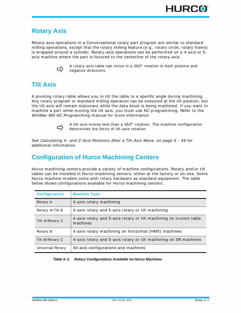
WinMax Mill Options 704-0116-415 Rotary 5-3
Rotary Axis
Rotary-axis operations in a Conversational rotary part program are similar to standard milling operations, except that the rotary milling feature (e.g., rotary circle, rotary frame) is wrapped around a cylinder. Rotary-axis operations can be performed on a 4-axis or 5-axis machine where the part is fixtured to the centerline of the rotary-axis.
Tilt Axis
A pivoting rotary table allows you to tilt the table to a specific angle during machining. Any rotary program or standard milling operation can be executed at the tilt position, but the tilt-axis will remain stationary while the data block is being machined. If you want to machine a part while moving the tilt axis, you must use NC programming. Refer to the WinMax Mill NC Programming manual for more information.
See Calculating X- and Z-Axis Positions After a Tilt-Axis Move, on page 5 - 49 for additional information.
Configuration of Hurco Machining Centers
Hurco machining centers provide a variety of machine configurations. Rotary and/or tilt tables can be installed in Hurco machining centers, either at the factory or on-site. Some Hurco machine models come with rotary hardware as standard equipment. The table below shows configurations available for Hurco machining centers.
Table 5–1. Rotary Configurations Available on Hurco Machines
A rotary-axis table can move in a 360º rotation in both positive and negative directions.
A tilt-axis moves less than a 360º rotation. The machine configuration determines the limits of tilt-axis rotation.
Configuration Machine Type
Rotary A 4-axis rotary machining
Rotary A/Tilt B 4-axis rotary and 5-axis rotary or tilt machining
Tilt A/Rotary C 4-axis rotary and 5-axis rotary or tilt machining on trunion table machines
Rotary B 4-axis rotary machining on horizontal (HMX) machines
Tilt B/Rotary C 4-axis rotary and 5-axis rotary or tilt machining on SR machines
Universal Rotary All axis configurations and machines

5 - 4 Rotary 704-0116-415 WinMax Mill Options
Setting the Axis Configuration
You must set the axis configuration in the Conversational part program before you program rotary or tilt operations. Follow these steps to set the axis configuration:
1. Press the Auxiliary console button to access the Auxiliary screen.
2. Select the Utilities icon from the Auxiliary screen.
3. Select the USER PREFERENCES F2 softkey.
4. Select the CONVERSATIONAL SETTINGS F2 softkey.
5. Select the axis configuration from the Default Conversational Program Type drop-down list or softkeys on the Conversational Settings screen (configurations listed below are not available for all Hurco models):
• Rotary A—Rotary axis
• Rotary A Tilt B—Rotary and/or tilt axis
• Tilt A Rotary C—Rotary and /or tilt axis
• Rotary B—Rotary axis
• Tilt B Rotary C—SR only
• Universal Rotary—all configurations
Select the axis configuration for all of the axes on your machine, even if you don’t think they will be used in the program. Rotary- and/or tilt-axis data blocks can be added to an existing program as long as the rotary-axis and/or tilt-axis configuration was selected when the program was first created.
Once an axis configuration is set for a program, it cannot be changed. However, you can use an existing Conversational program to create a new program that contains rotary-axis and/or tilt-axis programming data blocks. Follow these steps to create the new program:
1. Create a new Conversational program with the rotary-axis or tilt-axis configuration for your machine.
2. Select the IMPORT FUNCTIONS F6 softkey from the Input screen to pull in all data blocks and setups from an existing Conversational part program. Refer to Getting Started with WinMax Mill for more information.
3. Add rotary-axis or tilt-axis operations in the new program.
4. Save the new program under a new name. You now have a rotary-axis and/or tilt-axis version and a standard version of the same Conversational part program.
WinMax Mill Options 704-0116-415 Rotary 5-5
Transform Plane
Hurco’s Transform Plane feature can be used with 4-axis or 5-axis machining centers to machine non-rotary milling or drilling features on multiple sides (i.e., planes) of a workpiece. Part zero is reestablished for each transformed plane in a Transform Plane Reference Points data block; the tool automatically moves so that it is always perpendicular to the transformed plane.
Transform Plane can be used in a WinMax Mill 4-axis or 5-axis part program or as part of a VMX42SR part program. Using Transform Plane has the following benefits:
• Reduces setup time and potential positioning errors because the part doesn’t have to be refixtured each time the plane is transformed.
• Eliminates programming errors because the machine reestablishes part zero for each transformed plane.
• Allows a non-rotary milling or drilling feature to be machined on one or more sides of an irregularly-shaped workpiece.
Rotary Transform Plane Block
Transform Plane is used in a Conversational rotary program to position part zero for a non-rotary data block to any orientation of any plane of your rotary- or tilt-axis machine. For example, use Transform Plane when you want to repeat a non-rotary feature (e.g., mill contour, holes) on multiple sides of a part.
These are the Rotary Transform Plane fields:
• Location—The location number of the transformed plane.
• X—the X offset value.
• Y—the Y offset value.
• Z—the Z offset value.
Follow these steps to use Transform Plane in a rotary part program:
1. Create the non-rotary milling or drilling feature on the X-Y plane (i.e., create the milling or drilling feature as a 3-axis part) in a Conversational rotary part program.
2. Insert a Rotary Position data block to define the orientation of the transformed plane (i.e., position of the part) for the non-rotary data block.
Transform Plane can only be used in a rotary part program.
Rotary Pattern Loop and Rotary Pattern Locations data blocks can not be used within a Transform Plane operation.
Non-rotary patterns cannot be in effect (i.e., must be closed with a Pattern End data block) prior to a Transform Plane operation.
5 - 6 Rotary 704-0116-415 WinMax Mill Options
Select the Rotary Position F1 softkey to access the Rotary Position data block from a rotary data block.
3. On the Rotary Position data block, select Yes for the Transform Part Zero field to activate Transform Plane for non-rotary data blocks in the rotary part
• Use Offset Z (Zero Calibration mode only)—determines whether or not the value in the Offset Z field on the Part Setup screen will be used by the machine in a transformed plane. The default value is No. Refer to Rotary Part Setup, on page 5 - 8 for information about the Offset Z field.
• When set to Yes, the value in the Offset Z field on the Part Setup screen will be used to establish the part zero coordinate system in Transform Plane operations.
• When set to No, the value in the Offset Z field on the Part Setup screen will be added or subtracted from the Z calibration point during Transform Plane operations.
4. Define the X-Y-Z position of part zero for the transformed plane in the Transform Plane Reference Points data block.
• Follow these steps to access the Transform Plane Reference Points data block from a rotary data block:
a. Select the Rotary Patterns F6 softkey.b. Select the Transform Plane F3 softkey.
5. Add a Transform Plane End data block to end the Transform Plane operation. There are no fields in the Transform Plane End data block.
Follow these steps to access the Transform Plane End data block from a rotary data block:
a. Select the Rotary Patterns F6 softkey.b. Select the Transform Plane End F4 softkey.
The Rotary Position data block must be placed immediately prior to the Transform Plane Reference Points data block (see step 4) in the part program.
Although the Transform Plane Reference Points data block resembles a Pattern Locations data block, it behaves differently. The X, Y, and Z fields on a Transform Plane Reference Points data block establishes part zero for the non-rotary feature on the current transformed plane.
If the non-rotary milling or drilling feature will be repeated at multiple locations on a transformed plane but at the same orientation, you can use one Transform Plane Reference Points data block to define all the X-Y-Z locations.
After the Transform Plane End data block has executed, the orientation of the part will remain at the position defined in the most recent Rotary Position data block.
If the part program continues beyond the Transform Plane operation, another Rotary Position data block will be required if the part must be reorientated to a different position.

WinMax Mill Options 704-0116-415 Rotary 5-7
Rotary Transform Plane End Block
The Transform Plane End block ends the Transform Plane operation.
After the Transform Plane End data block has executed, the orientation of the part will remain at the position defined in the most recent Rotary Position data block.
If the part program continues beyond the Transform Plane operation, another Rotary Position data block will be required if the part must be reorientated to a different position.
See Transform Plane Example Programs, on page 5 - 62 for more information.
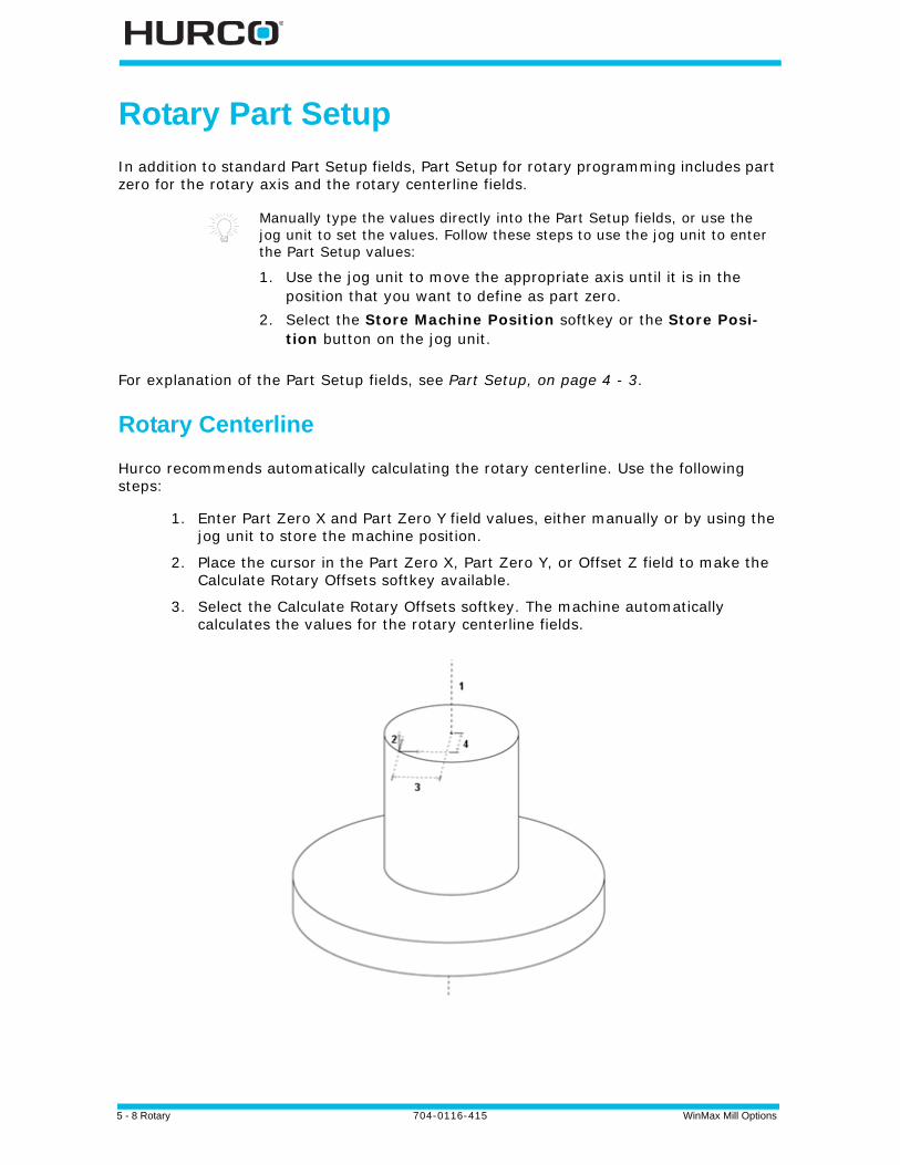
5 - 8 Rotary 704-0116-415 WinMax Mill Options
Rotary Part Setup
In addition to standard Part Setup fields, Part Setup for rotary programming includes part zero for the rotary axis and the rotary centerline fields.
For explanation of the Part Setup fields, see Part Setup, on page 4 - 3.
Rotary Centerline
Hurco recommends automatically calculating the rotary centerline. Use the following steps:
1. Enter Part Zero X and Part Zero Y field values, either manually or by using the jog unit to store the machine position.
2. Place the cursor in the Part Zero X, Part Zero Y, or Offset Z field to make the Calculate Rotary Offsets softkey available.
3. Select the Calculate Rotary Offsets softkey. The machine automatically calculates the values for the rotary centerline fields.
Manually type the values directly into the Part Setup fields, or use the jog unit to set the values. Follow these steps to use the jog unit to enter the Part Setup values:
1. Use the jog unit to move the appropriate axis until it is in the position that you want to define as part zero.
2. Select the Store Machine Position softkey or the Store Posi-tion button on the jog unit.
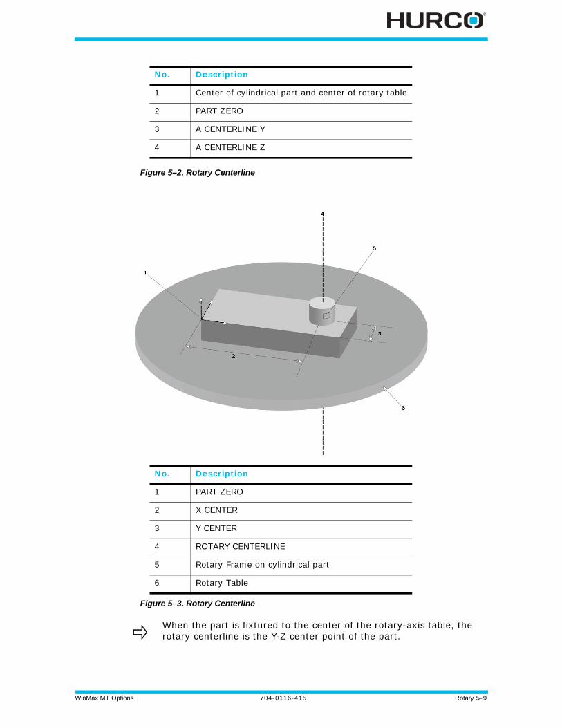
WinMax Mill Options 704-0116-415 Rotary 5-9
Figure 5–2. Rotary Centerline
Figure 5–3. Rotary Centerline
No. Description
1 Center of cylindrical part and center of rotary table
2 PART ZERO
3 A CENTERLINE Y
4 A CENTERLINE Z
No. Description
1 PART ZERO
2 X CENTER
3 Y CENTER
4 ROTARY CENTERLINE
5 Rotary Frame on cylindrical part
6 Rotary Table
When the part is fixtured to the center of the rotary-axis table, the rotary centerline is the Y-Z center point of the part.

5 - 10 Rotary 704-0116-415 WinMax Mill Options
Rotary Part Programming
Part program type is dependent upon machine configuration:
• Rotary A—4-axis rotary machining
• Rotary A Tilt B—4-axis rotary and 5-axis rotary or tilt machining
• Tilt A Rotary C—4-axis rotary and 5-axis rotary or tilt machining on trunion table machines
• Rotary B—4-axis rotary machining on horizontal machines
• Tilt B Rotary C—4-axis rotary and 5-axis rotary or tilt machining on SR machines
• Universal—all axis configurations and machines
See Configuration of Hurco Machining Centers, on page 5 - 3 for information about setting the program type.
The following sections contain details about the program blocks for each configuration:
Rotary A and Rotary A Tilt B Configuration . . . . . . . . . . . . . . . . . . . . . . . . . 5 - 14
Tilt A Rotary C Configuration . . . . . . . . . . . . . . . . . . . . . . . . . . . . . . . . . . . 5 - 20
Rotary B Configuration . . . . . . . . . . . . . . . . . . . . . . . . . . . . . . . . . . . . . . . 5 - 26
Tilt B Rotary C Configuration . . . . . . . . . . . . . . . . . . . . . . . . . . . . . . . . . . . 5 - 29
Universal Rotary Configuration . . . . . . . . . . . . . . . . . . . . . . . . . . . . . . . . . . 5 - 35
Rotary New Block
Rotary New Block is the same for all configurations. When you select the Rotary softkey a new data block will appear with the following softkeys:
• Rotary Position—moves all axes, including the rotary axis. See Rotary Position Block, on page 5 - 11.
• Rotary Milling—access the Rotary Lines and Arcs, Circle, Frame, True-Type Font, Slot, and Polygon data blocks. See Rotary Milling New Block, on page 5 - 12.
• Rotary Patterns—access the Rotary Pattern Loop, Rotary Pattern Locations, Rectangular, Mirror, and Transform Plane data blocks to repeat a rotary feature on a cylinder. See Rotary Patterns, on page 5 - 12.
• Rotary Parameters—define the parameters of the cylinder. See Rotary Parameters, on page 5 - 13.
Tool changes are completed before each rotary data block is executed. The tool change will be automatic or the machine will prompt for manual insertion of the tool specified in the data block.
Refer to Example Programs, on page 5 - 51 for sample part programs.

WinMax Mill Options 704-0116-415 Rotary 5-11
Rotary Position Block
A Rotary Position data block is used to move the machine’s axes to a specific location at Rapid feedrate. A new Rotary Position data block is required each time the rotary-axis must be repositioned in the part program.
The tool will move to the Retract Plane, Safety Plane, or Home Z position before the table rotates into position each time a Rotary Position data block with rotary-axis positioning is executed in a Conversational part program.
Rotary Position Block fields are dependent upon machine axis configuration. Fields for all configurations except Universal are listed below. See Rotary Position Block, on page 5 - 35 for Universal Rotary Position block fields.
• Stop—when set to Yes, pauses program execution after the Rotary Position data block is executed. To restart the program, press the Start Cycle console button.
• X Position—X-axis coordinate relative to Part Zero X.
• Y Position—Y-axis coordinate relative to Part Zero Y.
• A Angle, B Angle, or C Angle—rotary-axis coordinate (angle) relative to Part Zero A, Part Zero B, or Part Zero C, depending on the configuration of your machine.
• Rotary Safety Move—when set to Yes, moves the X and Y axes to the locations defined in X and Y Safety Position fields (described below) before rotary-axis orientation.
• X, Y Safety Position—when the Rotary Safety Move field (described above) is set to Yes, defines the location to which X and Y axes will move before the rotary-axis orients.
• Transform Part Zero—when set to Yes, used to activate Transform Plane for a non-rotary data block machined on multiple sides of a part. Refer to Rotary Transform Plane, on page 5 - 48 for information about using Transform Plane in a Conversational rotary part program.
• Use Offset Z (Zero Calibration mode only)—available when Transform Part Zero is Yes. Determines whether or not the value in the Offset Z field on the Part Setup screen will be used by the machine in a transformed plane. The default value is No. Refer to Rotary Part Setup, on page 5 - 8 for information about the Offset Z field.
• When set to Yes, the value in the Offset Z field on the Part Setup screen will be used to establish the part zero coordinate system in Transform Plane operations.
• When set to No, the value in the Offset Z field on the Part Setup screen will be added or subtracted from the Z calibration point during
A Rotary Position data block should be included as the first data block in a Conversational rotary part program to define the initial orientation of the rotary axis.
Set the Rotary Safety Move field to Yes if there is a potential for collision between the rotary axis and the spindle.

5 - 12 Rotary 704-0116-415 WinMax Mill Options
Transform Plane operations.
• Z Move Type—select the level to which Z-axis retracts at the beginning of the Rotary Position data block.
• Z Home—Z-axis will move at Rapid feedrate to the position defined in Z Machine field.
• Z Safety—Z-axis will move at Rapid feedrate to the position defined in the Part Limit Z (+) field on the Part Setup screen.
• Tool—number of the tool that will cut the part, entered on the Tool Setup screen.
Rotary Milling New Block
Rotary Milling New Block is the same for all configurations. These softkeys appear on the Rotary Milling New Block screen:
• Rotary Lines And Arcs—access the Rotary Mill Contour data block to create lines and arcs on a cylinder.
• Rotary Circle—access the Rotary Mill Circle data block to create a circle on a cylinder.
• Rotary Frame—access the Rotary Mill Frame data block to create a frame on a cylinder.
• Rotary True Type Font (available with Universal Rotary configuration only)—access the Rotary True Type font data block to create text on a cylinder.
• Rotary Slot (available with Universal Rotary configuration only)—access the Rotary Slot data block to create a slot on a cylinder.
• Rotary Polygon (available with Universal Rotary configuration only)—access the Rotary Polygon data block to create a polygon on a cylinder.
• Rotary Stick Lettering (available with Universal Rotary configuration only) — access the Rotary Stick Lettering data block to create text on a cylinder.
Rotary Patterns
Rotary patterns allow you to repeat a mill feature (e.g., rotary circle, rotary frame, holes) on the part. These are the softkeys on the Rotary Patterns data block:
• Rotary Loop—repeats a pattern along the X-A plane on a cylindrical part.
• Rotary Locations—repeats a mill feature anywhere on a cylindrical part.
• Rotary Rectangular (available only with Universal Rotary configuration)—repeats a rectangle on a cylindrical part.
• Rotary Mirror (available only with Universal Rotary configuration)—repeats a pattern as a mirror image.
• Transform Plane—activates Transform Plane feature.
• Transform Plane End—ends a Transform Plane operation.
• Pattern End—ends a rotary pattern loop or rotary locations operation.

WinMax Mill Options 704-0116-415 Rotary 5-13
Rotary Parameters
The Rotary Parameters data block is used to set the radius of the cylindrical part and to define the Y Off of Centerline parameter.
These are the fields on the Rotary Parameters data block:
• Cylinder Radius (all configurations except Tilt B Rotary C)—radius of the cylindrical part. If the radius is a negative number, the tool will cut the rotary mill feature (e.g., rotary circle, rotary frame) from the top to bottom.
• Y Off Of Centerline (Rotary A and Rotary A Tilt B configurations only)—determines where the tool will locate the Y coordinate. The default selection is No.
• If set to No, the tool will position the Y coordinate (specified in the A Centerline Y field on the Part Setup screen) directly over the centerline of the rotary axis when cutting a rotary mill feature (e.g., rotary circle, rotary frame).
• If set to Yes, the tool will stay at the current Y coordinate (specified in the A Centerline Y field on the Part Setup screen) when cutting a rotary mill feature (e.g., rotary circle, rotary frame).
• Rotary Centerline X (Tilt B Rotary C configuration only)—the distance from part zero to the vertical axis around which the part will rotate.
• Rotary Centerline Y (Tilt B Rotary C configuration only)—the distance from part zero to the horizontal axis around which the part will rotate.
If the radius of the cylindrical part is not defined in the Rotary Parameters data block and Cutter Compensation is used in rotary lines and arcs, the machine will define the part’s radius as the distance from Z Start to the rotary centerline.
5 - 14 Rotary 704-0116-415 WinMax Mill Options
Rotary A and Rotary A Tilt B Configuration
Rotary Position
The Rotary Position data block is available with multiple rotary configurations; see Rotary Position Block, on page 5 - 11 for an explanation of the softkeys on this screen.
Rotary Lines and Arcs
Rotary line and arc segments are used to create a rotary mill contour. A rotary mill contour is similar to a standard mill contour, except the rotary contour is wrapped around a cylinder.
Start Segment
These are the fields on the Rotary Mill Contour Start Segment data block:
• X Start—X-axis coordinate for first segment’s starting point.
• A Angle—rotary-axis coordinate (angle) for the first segment’s starting point.
• Z Start—point where the Z-axis plunge feedrate begins.
• Z Bottom—the bottom of the finished segment and the location where the Z-axis plunge feedrate ends.
Line Segment
These are the fields on the Rotary Mill Contour Line segment data block:
• X End—X-axis coordinate for ending point of the line.
• A End—rotary-axis coordinate (angle) for the ending point of the line.
• Z End—Z-axis coordinate for the ending point of the line. The Z End value is the depth of the cut at the line end point and is carried forward from the previous segment. Retain the Z End value or type in a new value.
• X Start—X-axis coordinate start point programmed in the previous segment. The value of X Start can be changed only in the segment in which it was created.
• A Start—rotary-axis start point coordinate programmed in the previous segment. The value of A Start can be changed only in the segment in which it was created.
• Z Start—point where the Z-axis plunge feedrate begins.
Arc Segment
These are the fields on the Rotary Mill Contour Arc segment data block:
• Direction—the direction of the arc from the start point, Clockwise or Counter Clockwise.
• X End—X-axis coordinate of the arc’s end point.
WinMax Mill Options 704-0116-415 Rotary 5-15
• A End—rotary-axis coordinate (angle) of the arc’s end point.
• Z END—point where the Z-axis plunge into the cylinder ends.
• X Center—X-axis coordinate of the arc’s center point.
• A Center—rotary-axis coordinate (angle) of the arc’s center point.
• Radius—the radius of the arc, if known.
• Sweep Angle—identifies the angular distance in degrees from the start point of the arc to the end point. The range is -360° to 360°.
• X Start—X-axis coordinate start point programmed in the previous segment. The value of X Start can be changed only in the segment in which it was created.
• A Start—rotary-axis coordinate start point programmed in the previous segment. The value of A Start can be changed only in the segment in which it was created.
• Z Start—Z-axis coordinate start point programming in the previous segment. The value of Z Start can be changed only in the segment in which it was created.
Blend Arc Segment
These are the fields on the Rotary Mill Contour Blend Arc segment data block:
• Radius—the radius of the arc, if known.
• X End—X-axis coordinate of the arc’s end point.
• A End—rotary-axis coordinate (angle) of the arc’s end point.
• X Center—X-axis coordinate of the arc’s center point.
• A Center—rotary-axis coordinate (angle) of the arc’s center point.
• Direction—the direction of the arc from the start point, Clockwise or Counterclockwise.
• X Start—X-axis coordinate start point programmed in the previous segment. The value of X Start can be changed only in the segment in which it was created.
• A Start—rotary-axis coordinate start point programmed in the previous segment. The value of A Start can be changed only in the segment in which it was created.
Mill Contour End Block
A Contour End data block is required to end rotary Mill Contour operations. There are no fields in the Contour End data block.

5 - 16 Rotary 704-0116-415 WinMax Mill Options
Rotary Circle
A rotary mill circle is similar to a standard mill circle, except the rotary mill circle is wrapped around a cylinder. These are the fields on the Rotary Mill Circle data block:
These are the Rotary Circle fields for Rotary A and Rotary A Tilt B:
• X Center—X-axis coordinate for the center point of the circle.
• A Center—rotary-axis coordinate (angle) for the center point of the circle.
• Radius—radius of the milled circle.
• Z Start—location where the Z-axis plunge feedrate begins.
• Z Bottom—location where the Z-axis plunge feedrate ends.
Rotary Frame
A rotary mill frame is similar to a mill frame, except the rotary mill frame is wrapped around a cylinder.
These are the Rotary Mill Frame fields for Rotary A and Rotary A Tilt B:
• X Corner—X-axis coordinate of any one of the four corners of the frame. This corner becomes the reference corner.
• A Corner—rotary-axis coordinate (angle) of the reference corner of the frame.
• X Length—X-axis coordinate measured from the reference corner.
• X Length is positive if the reference corner is at the left side of the rectangle.
• X Length is negative if the reference corner is at the right side of the rectangle.
• A Length—rotary-axis coordinate (angle) from the reference corner.
• A Length is positive if the location of the frame is clockwise from the reference corner.
• A Length is negative if the location of the frame is counter clockwise from the reference corner.
• Z Start—start point for the Z-axis plunge feedrate.
• Z Bottom—end point for the Z-axis plunge feedrate.
• Corner Radius—radius of the reference corner. This value will be the same for all corners of the rotary frame.
WinMax Mill Options 704-0116-415 Rotary 5-17
Rotary Patterns
The Rotary Patterns data block is available with multiple rotary configurations; see Rotary Patterns, on page 5 - 12 for an explanation of the softkeys on this screen. The specific pattern screens for Rotary A and Rotary A Tilt B are explained below.
Rotary Loop
A rotary loop defines the number and locations a mill feature will be repeated on a cylinder. The initial mill feature is located at part zero and all subsequent copies are at a specific distance along the X-A axis of the cylinder.
These are the Rotary Pattern Loop fields for Rotary A and Rotary A Tilt B:
• Number—total number of times the mill feature will be cut on the cylinder.
• X Distance—the distance on the X-axis between each repetition of the mill feature. The right-hand rule determines if X Distance is positive or negative.
• A Distance—the distance (angle) on the rotary-axis between each repetition of the mill feature.
• B Distance (Rotary A Tilt B configuration only)—the distance (angle) on the tilt axis between each repetition of the mill feature.
A rotary Pattern End data block is required to end the sequence repeated in the Rotary Pattern Loop data block.
Rotary pattern and standard pattern data blocks can be nested (i.e., entirely contained within another pattern). The order of execution for nested rotary pattern and standard pattern data blocks is from the inside to the outside.
This is an example of nested data blocks in a program (the indentations are used illustrate the order of execution; your Conversational part program will not have these indentations).
In the following example, this is the order of execution:
1. Holes and rotary Mill Frame operations contained within the Pattern Loop Rotate data block.
2. Standard Mill Circle operation contained within the Rotary Pattern Loop data block.
Rotary Pattern Loop Standard Mill Circle (or any other rotary or non-rotary data blocks) Pattern Loop Rotate Holes operation Rotary Mill Frame (or other rotary or non-rotary data blocks) Pattern End (ends the Pattern Loop Rotate) Pattern End (ends the Rotary Pattern Loop)
Only one Rotary Position data block is required for nested Rotary Pattern Loop data blocks.
5 - 18 Rotary 704-0116-415 WinMax Mill Options
Rotary Locations
The Rotary Pattern Locations data block is used to create a list of locations of a mill feature repeated on a cylinder. Up to 999 copies can be located anywhere on the part.
Each set of locations listed on the Rotary Patterns Location data block is a specific location on the cylinder, relative to part zero. If you want the mill feature to be cut at part zero, you must define the coordinates of part zero in one of the sets of locations.
These are the Rotary Pattern Locations fields for Rotary A and Rotary A Tilt B:
• X—X-axis coordinate where the mill feature will be located on the part.
• Y—Y-axis coordinate where the mill feature will be located on the part.
• Z—offset for the Z axis. Z is used when a vise or other fixture holds multiple parts at different levels.
• A—rotary-axis coordinate (angle) where the mill feature will be located on the part.
• B—tilt-axis coordinate (angle) where the mill feature will be located on the part.
Rotary Transform Plane
The Rotary Transform Plane data block is available with multiple rotary configurations; see Rotary Transform Plane Block, on page 5 - 5 for an explanation of the fields on this screen.
A rotary Pattern End data block is required to end the sequence in the Rotary Pattern Locations data block.
After the rotary Pattern End data block has executed, the orientation of the machine axes will remain at the position defined in the most recent Rotary Position data block.
If the part program continues beyond the Rotary Pattern operation, another Rotary Position data block will be required if the axes must be reoriented to a different position.
WinMax Mill Options 704-0116-415 Rotary 5-19
Pattern End
A Pattern End data block is required to end rotary Pattern Loop and rotary Pattern Locations operations. There are no fields in the Pattern End data block.
Rotary Parameters
The Rotary Parameters data block is available with multiple rotary configurations; see Rotary Parameters, on page 5 - 13 for an explanation of the fields on this screen.
After the rotary Pattern End data block has executed, the orientation of the machine axes will remain at the position defined in the most recent Rotary Position data block.
If the part program continues beyond the Rotary Pattern operation, another Rotary Position data block will be required if the axes must be reoriented to a different position.
• A Rotary Pattern Loop data block only modifies the rotary operations contained within the pattern.
• The subsequent Rotary Position data block defines the orientation of the machine axes after the pattern is executed, and can provide a reference point if Recovery Restart is used.
• If the Rotary Pattern End data block is the last data block of the part program, a subsequent Rotary Position data block is not necessary.
• If a non-rotary operation data block (e.g., holes operation) is used in a rotary loop, a Rotary Position data block is required before the non-rotary operation data block to position the axes before the operation is executed in the loop.
5 - 20 Rotary 704-0116-415 WinMax Mill Options
Tilt A Rotary C Configuration
Rotary Position
The Rotary Position data block is available with multiple rotary configurations; see Rotary Position Block, on page 5 - 11 for an explanation of the fields on this screen.
Rotary Lines and Arcs
Rotary line and arc segments are used to create a rotary mill contour. A rotary mill contour is similar to a standard mill contour, except the rotary contour is wrapped around a cylinder.
Start Segment
These are the fields on the Rotary AC Mill Contour Start segment data block:
• C Angle—rotary-axis coordinate (angle) for the first segment’s starting point.
• Y Start—Y-axis coordinate for first segment’s starting point.
• Z Start—point where the Z-axis plunge feedrate begins.
• Z Bottom—the bottom of the finished segment and the location where the Z-axis plunge feedrate ends.
Line Segment
These are the fields on the Rotary AC Mill Contour Line segment data block:
• C End—C-axis coordinate for ending point of the line.
• Y End—rotary-axis coordinate (angle) for the ending point of the line.
• Z End—Z-axis coordinate for the ending point of the line. The Z End value is the depth of the cut at the line end point and is carried forward from the previous segment. Retain the Z End value or type in a new value.
• C Start—C-axis coordinate start point programmed in the previous segment. The value of C Start can be changed only in the segment in which it was created.
• Y Start—rotary-axis start point coordinate programmed in the previous segment. The value of Y Start can be changed only in the segment in which it was created.
• Z Start—point where the Z-axis plunge feedrate begins.
Arc Segment
These are the fields on the Rotary AC Mill Contour Arc segment data block:
• Direction—the direction of the arc from the start point, Clockwise or Counter Clockwise.
• C End—rotary-axis coordinate (angle) of the arc’s end point.
WinMax Mill Options 704-0116-415 Rotary 5-21
• Y End—Y-axis coordinate of the arc’s end point.
• Z End—point where the Z-axis plunge into the cylinder ends.
• C Center—rotary-axis coordinate (angle) of the arc’s center point.
• Y Center—Y-axis coordinate of the arc’s center point.
• Radius—the radius of the arc, if known.
• Sweep Angle—identifies the angular distance in degrees from the start point of the arc to the end point. The range is -360° to 360°.
• C Start—rotary-axis coordinate start point programmed in the previous segment. The value of C Start can be changed only in the segment in which it was created.
• Y Start—Y-axis coordinate start point programmed in the previous segment. The value of Y Start can be changed only in the segment in which it was created.
• Z Start—Z-axis coordinate start point programming in the previous segment. The value of Z Start can be changed only in the segment in which it was created.
Blend Arc
These are the fields on the Rotary AC Mill Contour Blend Arc segment data block:
• Radius—the radius of the arc, if known.
• C End—rotary-axis coordinate (angle) of the arc’s end point.
• Y End—Y-axis coordinate of the arc’s end point.
• C Center—rotary-axis coordinate (angle) of the arc’s center point.
• Y Center—Y-axis coordinate of the arc’s center point.
• Direction—the direction of the arc from the start point, Clockwise or Counterclockwise.
• C Start—rotary-axis coordinate start point programmed in the previous segment. The value of C Start can be changed only in the segment in which it was created.
• Y Start—Y-axis coordinate start point programmed in the previous segment. The value of Y Start can be changed only in the segment in which it was created.
Mill Contour End Block
A Contour End data block is required to end rotary Mill Contour operations. There are no fields in the Contour End data block.
5 - 22 Rotary 704-0116-415 WinMax Mill Options
Rotary Circle
A rotary mill circle is similar to a standard mill circle, except the rotary mill circle is wrapped around a cylinder. These are the fields on the Rotary Mill Circle data block:
These are the fields on the Rotary AC Mill Circle data block:
• C Center—rotary-axis coordinate (angle) for the center point of the circle.
• Y Center—Y-axis coordinate for the center point of the circle.
• Radius—radius of the milled circle.
• Z Start—location where the Z-axis plunge feedrate begins.
• Z Bottom—location where the Z-axis plunge feedrate ends.
Rotary Frame
A rotary mill frame is similar to a mill frame, except the rotary mill frame is wrapped around a cylinder.
These are the fields on the Rotary AC Mill Frame data block:
• C Corner—rotary-axis coordinate (angle) of the reference corner of the frame.
• Y Corner—Y-axis coordinate of any one of the four corners of the frame. This corner becomes the reference corner.
• C Length—rotary-axis coordinate (angle) from the reference corner.
• C Length is positive if the location of the frame is clockwise from the reference corner.
• C Length is negative if the location of the frame is counter clockwise from the reference corner.
• Y Length—Y-axis coordinate measured from the reference corner.
• Y Length is positive if the reference corner is at the left side of the rectangle.
• Y Length is negative if the reference corner is at the right side of the rectangle.
• Z Start—start point for the Z-axis plunge feedrate.
• Z Bottom—end point for the Z-axis plunge feedrate.
• Corner Radius—radius of the reference corner. This value will be the same for all corners of the rotary frame.

WinMax Mill Options 704-0116-415 Rotary 5-23
Rotary Patterns
The Rotary Patterns data block is available with multiple rotary configurations; see Rotary Patterns, on page 5 - 12 for an explanation of the softkeys on this screen. The specific pattern data blocks for Tilt A Rotary C are explained below.
Rotary Loop
A rotary loop defines the number and locations a mill feature will be repeated on a cylinder. The initial mill feature is located at part zero and all subsequent copies are at a specific distance along the X-A axis of the cylinder.
These are the fields on the Rotary Pattern Loop data block for Tilt A Rotary C:
• Number—total number of times the mill feature will be cut on the cylinder.
• Z Distance—the distance on the Z-axis between each repetition of the mill feature. The right-hand rule determines if Distance is positive or negative.
• A Distance—the distance (angle) on the rotary-axis between each repetition of the mill feature.
• C Distance—the distance (angle) on the tilt axis between each repetition of the mill feature.
A rotary Pattern End data block is required to end the sequence repeated in the Rotary Pattern Loop data block.
Rotary pattern and standard pattern data blocks can be nested (i.e., entirely contained within another pattern). The order of execution for nested rotary pattern and standard pattern data blocks is from the inside to the outside.
This is an example of nested data blocks in a program (the indentations are used illustrate the order of execution; your Conversational part program will not have these indentations).
In the following example, this is the order of execution:
1. Holes and rotary Mill Frame operations contained within the Pattern Loop Rotate data block.
2. Standard Mill Circle operation contained within the Rotary Pattern Loop data block.
Rotary Pattern Loop Standard Mill Circle (or any other rotary or non-rotary data blocks) Pattern Loop Rotate Holes operation Rotary Mill Frame (or other rotary or non-rotary data blocks) Pattern End (ends the Pattern Loop Rotate) Pattern End (ends the Rotary Pattern Loop)
Only one Rotary Position data block is required for nested Rotary Pattern Loop data blocks.

5 - 24 Rotary 704-0116-415 WinMax Mill Options
Rotary Locations
The Rotary Pattern Locations data block is used to create a list of locations of a mill feature repeated on a cylinder. Up to 999 copies can be located anywhere on the part.
Each set of locations listed on the Rotary Patterns Location data block is a specific location on the cylinder, relative to part zero. If you want the mill feature to be cut at part zero, you must define the coordinates of part zero in one of the sets of locations.
These are the fields on the Rotary Pattern Locations data block for Tilt A Rotary C:
• X—X-axis coordinate where the mill feature will be located on the part.
• Y—Y-axis coordinate where the mill feature will be located on the part.
• Z—offset for the Z axis. Z is used when a vise or other fixture holds multiple parts at different levels.
• A—rotary-axis coordinate (angle) where the mill feature will be located on the part.
• C—rotary-axis coordinate (angle) where the mill feature will be located on the part.
Rotary Transform Plane
The Rotary Transform Plane data block is available with multiple rotary configurations; see Rotary Transform Plane Block, on page 5 - 5 for an explanation of the fields on this screen.
A rotary Pattern End data block is required to end the sequence in the Rotary Pattern Locations data block.
After the rotary Pattern End data block has executed, the orientation of the machine axes will remain at the position defined in the most recent Rotary Position data block.
If the part program continues beyond the Rotary Pattern operation, another Rotary Position data block will be required if the axes must be reoriented to a different position.

WinMax Mill Options 704-0116-415 Rotary 5-25
Pattern End
A Pattern End data block is required to end rotary Pattern Loop and rotary Pattern Locations operations. There are no fields in the Pattern End data block.
Rotary Parameters
The Rotay Parameters data block is available with multiple rotary configurations; see Rotary Parameters, on page 5 - 13 for an explanation of the fields on this screen.
After the rotary Pattern End data block has executed, the orientation of the machine axes will remain at the position defined in the most recent Rotary Position data block.
If the part program continues beyond the Rotary Pattern operation, another Rotary Position data block will be required if the axes must be reoriented to a different position.
• A Rotary Pattern Loop data block only modifies the rotary operations contained within the pattern.
• The subsequent Rotary Position data block defines the orientation of the machine axes after the pattern is executed, and can provide a reference point if Recovery Restart is used.
• If the Rotary Pattern End data block is the last data block of the part program, a subsequent Rotary Position data block is not necessary.
• If a non-rotary operation data block (e.g., holes operation) is used in a rotary loop, a Rotary Position data block is required before the non-rotary operation data block to position the axes before the operation is executed in the loop.
5 - 26 Rotary 704-0116-415 WinMax Mill Options
Rotary B Configuration
Rotary B configuration is used with horizontal (HMX) machines.
Rotary Position
The Rotary Position data block is available with multiple rotary configurations; see Rotary Position Block, on page 5 - 11 for an explanation of the fields on this screen.
Rotary Milling
For rotary milling programs on an HMX machine, Universal Rotary configuration must be used; see Universal Rotary Configuration, on page 5 - 35.
Rotary Patterns
The Rotary Patterns data block is available with multiple rotary configurations; see Rotary Patterns, on page 5 - 12 for an explanation of the softkeys on this screen. The specific pattern data blocks for Rotary B configuration are explained below.
Rotary Loop
A rotary loop defines the number and locations a mill feature will be repeated on a cylinder. The initial mill feature is located at part zero and all subsequent copies are at a specific distance along the X-A axis of the cylinder.
These are the fields on the Rotary Pattern Loop data block for Rotary B:
• Number—total number of times the mill feature will be cut on the cylinder.
• Z Distance—the distance on the Z-axis between each repetition of the mill feature. The right-hand rule determines if Distance is positive or negative.
• B Distance —the distance (angle) on the rotary axis between each repetition of the mill feature.
A rotary Pattern End data block is required to end the sequence repeated in the Rotary Pattern Loop data block.
WinMax Mill Options 704-0116-415 Rotary 5-27
Rotary Locations
The Rotary Pattern Locations data block is used to create a list of locations of a mill feature repeated on a cylinder. Up to 999 copies can be located anywhere on the part.
Each set of locations listed on the Rotary Patterns Location data block is a specific location on the cylinder, relative to part zero. If you want the mill feature to be cut at part zero, you must define the coordinates of part zero in one of the sets of locations.
These are the fields on the Rotary Pattern Locations data block for Rotary B:
• X—X-axis coordinate where the mill feature will be located on the part.
• Y—Y-axis coordinate where the mill feature will be located on the part.
• Z—offset for the Z axis. Z is used when a vise or other fixture holds multiple parts at different levels.
• B—rotary-axis coordinate (angle) where the mill feature will be located on the part.
Rotary pattern and standard pattern data blocks can be nested (i.e., entirely contained within another pattern). The order of execution for nested rotary pattern and standard pattern data blocks is from the inside to the outside.
This is an example of nested data blocks in a program (the indentations are used illustrate the order of execution; your Conversational part program will not have these indentations).
In the following example, this is the order of execution:
1. Holes and rotary Mill Frame operations contained within the Pattern Loop Rotate data block.
2. Standard Mill Circle operation contained within the Rotary Pattern Loop data block.
Rotary Pattern Loop Standard Mill Circle (or any other rotary or non-rotary data blocks) Pattern Loop Rotate Holes operation Rotary Mill Frame (or other rotary or non-rotary data blocks) Pattern End (ends the Pattern Loop Rotate) Pattern End (ends the Rotary Pattern Loop)
Only one Rotary Position data block is required for nested Rotary Pattern Loop data blocks.
A rotary Pattern End data block is required to end the sequence in the Rotary Pattern Locations data block.
5 - 28 Rotary 704-0116-415 WinMax Mill Options
Rotary Transform Plane
The Rotary Transform Plane data block is available with multiple rotary configurations; see Rotary Transform Plane Block, on page 5 - 5 for an explanation of the fields on this screen.
Pattern End
A Pattern End data block is required to end rotary Pattern Loop and rotary Pattern Locations operations. There are no fields in the Pattern End data block.
Rotary Parameters
The Rotary Parameters data block is available with multiple rotary configurations; see Rotary Parameters, on page 5 - 13 for an explanation of the fields on this screen.
After the rotary Pattern End data block has executed, the orientation of the machine axes will remain at the position defined in the most recent Rotary Position data block.
If the part program continues beyond the Rotary Pattern operation, another Rotary Position data block will be required if the axes must be reoriented to a different position.
• A Rotary Pattern Loop data block only modifies the rotary operations contained within the pattern.
• The subsequent Rotary Position data block defines the orientation of the machine axes after the pattern is executed, and can provide a reference point if Recovery Restart is used.
• If the Rotary Pattern End data block is the last data block of the part program, a subsequent Rotary Position data block is not necessary.
• If a non-rotary operation data block (e.g., holes operation) is used in a rotary loop, a Rotary Position data block is required before the non-rotary operation data block to position the axes before the operation is executed in the loop.
WinMax Mill Options 704-0116-415 Rotary 5-29
Tilt B Rotary C Configuration
Rotary Position
The Rotary Position data block is available with multiple rotary configurations; see Rotary Position Block, on page 5 - 11 for an explanation of the fields on this screen.
Rotary Lines and Arcs
Rotary line and arc segments are used to create a rotary mill contour. A rotary mill contour is similar to a standard mill contour, except the rotary contour is wrapped around a cylinder.
Start Segment
These are the fields on the Rotary BC Mill Contour Start segment data block:
• Z Start—Z-axis coordinate for first segment’s starting point.
• C Angle—rotary-axis coordinate (angle) for the first segment’s starting point.
• Radius Start—point where the Z-axis plunge feedrate begins.
• Radius Bottom—the bottom of the finished segment and the location where the Z-axis plunge feedrate ends.
Line Segment
These are the fields on the Rotary BC Mill Contour Line segment data block:
• Z End—Z-axis coordinate for the ending point of the line. The Z End value is the depth of the cut at the line end point and is carried forward from the previous segment. Retain the Z End value or type in a new value.
• C End—C-axis coordinate for ending point of the line.
• Radius End—rotary-axis coordinate (angle) for the ending point of the line.
• Z Start—point where the Z-axis plunge feedrate begins.
• C Start—C-axis coordinate start point programmed in the previous segment. The value of C Start can be changed only in the segment in which it was created.
• Radius Start—rotary-axis start point coordinate programmed in the previous segment. The value of Radius Start can be changed only in the segment in which it was created.
Arc Segment
These are the fields on the Rotary BC Mill Contour Arc segment data block:
• Direction—the direction of the arc from the start point, Clockwise or Counter Clockwise.
• Z End—point where the Z-axis plunge into the cylinder ends.
• C End—rotary-axis coordinate (angle) of the arc’s end point.
5 - 30 Rotary 704-0116-415 WinMax Mill Options
• Radius End—Y-axis coordinate of the arc’s end point.
• Z Center—Z-axis coordinate of the arc’s center point.
• C Center—rotary-axis coordinate (angle) of the arc’s center point.
• Arc Radius—the radius of the arc, if known.
• Sweep Angle—identifies the angular distance in degrees from the start point of the arc to the end point. The range is -360° to 360°.
• Z Start—Z-axis coordinate start point programming in the previous segment. The value of Z Start can be changed only in the segment in which it was created.
• C Start—rotary-axis coordinate start point programmed in the previous segment. The value of C Start can be changed only in the segment in which it was created.
• Radius Start—Y-axis coordinate start point programmed in the previous segment. The value of Radius Start can be changed only in the segment in which it was created.
Blend Arc Segment
These are the fields on the Rotary BC Mill Contour Blend Arc segment data block:
• Arc Radius—the radius of the arc, if known.
• Z End—Z-axis coordinate of the arc’s end point.
• C End—rotary-axis coordinate (angle) of the arc’s end point.
• Z Center—Z-axis coordinate of the arc’s center point.
• C Center—rotary-axis coordinate (angle) of the arc’s center point.
• Direction—the direction of the arc from the start point, Clockwise or Counterclockwise.
• Z Start—Z-axis coordinate start point programmed in the previous segment. The value of Z Start can be changed only in the segment in which it was created.
• C Start—rotary-axis coordinate start point programmed in the previous segment. The value of C Start can be changed only in the segment in which it was created.
Mill Contour End Block
A Contour End data block is required to end rotary Mill Contour operations. There are no fields in the Contour End data block.
WinMax Mill Options 704-0116-415 Rotary 5-31
Rotary Circle
A rotary mill circle is similar to a standard mill circle, except the rotary mill circle is wrapped around a cylinder. These are the fields on the Rotary Mill Circle data block:
These are the fields on the Rotary BC Circle data block:
• Z Center—Z-axis coordinate for the center point of the circle.
• C Center—rotary-axis coordinate (angle) for the center point of the circle.
• Radius—radius of the milled circle.
• Radius Start—location where the Z-axis plunge feedrate begins.
• Radius Bottom—location where the Z-axis plunge feedrate ends.
Rotary Frame
A rotary mill frame is similar to a mill frame, except the rotary mill frame is wrapped around a cylinder.
These are the fields on the Rotary BC Mill Frame data block:
• Z Corner—Z-axis coordinate of any one of the four corners of the frame. This corner becomes the reference corner.
• C Corner—rotary-axis coordinate (angle) of the reference corner of the frame.
• Z Length—Z-axis coordinate measured from the reference corner.
• Z Length is positive if the reference corner is at the left side of the rectangle.
• Z Length is negative if the reference corner is at the right side of the rectangle.
• C Length—rotary-axis coordinate (angle) from the reference corner.
• C Length is positive if the location of the frame is clockwise from the reference corner.
• C Length is negative if the location of the frame is counter clockwise from the reference corner.
• Radius Start—start point for the Z-axis plunge feedrate.
• Radius Bottom—end point for the Z-axis plunge feedrate.
• Corner Radius—radius of the reference corner. This value will be the same for all corners of the rotary frame.
5 - 32 Rotary 704-0116-415 WinMax Mill Options
Rotary Patterns
The Rotary Patterns data block is available with multiple rotary configurations; see Rotary Patterns, on page 5 - 12 for an explanation of the softkeys on this screen. The specific pattern data blocks for Tilt B Rotary C configuration are explained below.
Rotary Loop
A rotary loop defines the number and locations a mill feature will be repeated on a cylinder. The initial mill feature is located at part zero and all subsequent copies are at a specific distance along the X-A axis of the cylinder.
These are the fields on the Rotary Pattern Loop data block for Tilt B Rotary C:
• Number—total number of times the mill feature will be cut on the cylinder.
• Z Distance—the distance on the Z-axis between each repetition of the mill feature. The right-hand rule determines if Distance is positive or negative.
• C Distance —the distance (angle) on the C-axis between each repetition of the mill feature.
A rotary Pattern End data block is required to end the sequence repeated in the Rotary Pattern Loop data block.
Rotary pattern and standard pattern data blocks can be nested (i.e., entirely contained within another pattern). The order of execution for nested rotary pattern and standard pattern data blocks is from the inside to the outside.
This is an example of nested data blocks in a program (the indentations are used illustrate the order of execution; your Conversational part program will not have these indentations).
In the following example, this is the order of execution:
1. Holes and rotary Mill Frame operations contained within the Pattern Loop Rotate data block.
2. Standard Mill Circle operation contained within the Rotary Pattern Loop data block.
Rotary Pattern Loop Standard Mill Circle (or any other rotary or non-rotary data blocks) Pattern Loop Rotate Holes operation Rotary Mill Frame (or other rotary or non-rotary data blocks) Pattern End (ends the Pattern Loop Rotate) Pattern End (ends the Rotary Pattern Loop)
Only one Rotary Position data block is required for nested Rotary Pattern Loop data blocks.
WinMax Mill Options 704-0116-415 Rotary 5-33
Rotary Locations
The Rotary Pattern Locations data block is used to create a list of locations of a mill feature repeated on a cylinder. Up to 999 copies can be located anywhere on the part.
Each set of locations listed on the Rotary Patterns Location data block is a specific location on the cylinder, relative to part zero. If you want the mill feature to be cut at part zero, you must define the coordinates of part zero in one of the sets of locations.
These are the fields on the Rotary Pattern Locations data block for Tilt B Rotary C:
• X—X-axis coordinate where the mill feature will be located on the part.
• Y—Y-axis coordinate where the mill feature will be located on the part.
• Z—offset for the Z axis. Z is used when a vise or other fixture holds multiple parts at different levels.
• B—rotary-axis coordinate (angle) where the mill feature will be located on the part.
• C—rotary-axis coordinate (angle) where the mill feature will be located on the part.
Rotary Transform Plane
The Rotary Transform Plane data block is available with multiple rotary configurations; see Rotary Transform Plane Block, on page 5 - 5 for an explanation of the fields on this screen.
A rotary Pattern End data block is required to end the sequence in the Rotary Pattern Locations data block.
After the rotary Pattern End data block has executed, the orientation of the machine axes will remain at the position defined in the most recent Rotary Position data block.
If the part program continues beyond the Rotary Pattern operation, another Rotary Position data block will be required if the axes must be reoriented to a different position.
5 - 34 Rotary 704-0116-415 WinMax Mill Options
Pattern End
A Pattern End data block is required to end rotary Pattern Loop and rotary Pattern Locations operations. There are no fields in the Pattern End data block.
Rotary Parameters
The Rotary Parameters data block is available with multiple rotary configurations; see Rotary Parameters, on page 5 - 13 for an explanation of the field on this screen.
After the rotary Pattern End data block has executed, the orientation of the machine axes will remain at the position defined in the most recent Rotary Position data block.
If the part program continues beyond the Rotary Pattern operation, another Rotary Position data block will be required if the axes must be reoriented to a different position.
• A Rotary Pattern Loop data block only modifies the rotary operations contained within the pattern.
• The subsequent Rotary Position data block defines the orientation of the machine axes after the pattern is executed, and can provide a reference point if Recovery Restart is used.
• If the Rotary Pattern End data block is the last data block of the part program, a subsequent Rotary Position data block is not necessary.
• If a non-rotary operation data block (e.g., holes operation) is used in a rotary loop, a Rotary Position data block is required before the non-rotary operation data block to position the axes before the operation is executed in the loop.
WinMax Mill Options 704-0116-415 Rotary 5-35
Universal Rotary Configuration
Rotary Position Block
A Rotary Position data block is used to move the machine’s axes to a specific location at Rapid feedrate. A new Rotary Position data block is required each time the rotary-axis must be repositioned in the part program.
The tool will move to the Retract Plane, Safety Plane, or Home Z position before the table rotates into position each time a Rotary Position data block with rotary-axis positioning is executed in a Conversational part program.
These are the fields on the Rotary Position data block:
• Stop—when set to Yes, pauses program execution after the Rotary Position data block is executed. To restart the program, press the Start Cycle console button.
First Move (Z Retract)
• Retract Type—select the Z level to which Z-axis retracts at the beginning of the Rotary Position data block.
• Z Home—Z-axis will move at Rapid feedrate to the position defined in Z Machine field.
• Z Position—Z-axis will move at Rapid feedrate to the position entered in the Z Position field.
• Z Position—the position to which Z-axis retracts when Z Position is selected for the Retract Type.
Second Move
• Enable—specify YES to enable axis movement
• X Position—defines the location to which the X axis will move before the rotary-axis orients.
• Y Position—defines the location to which the Y axis will move before the rotary-axis orients.
Third Move (End Position)
• X Position—X-axis coordinate relative to Part Zero X. Enabled when the Enable field is set to YES.
• Y Position—Y-axis coordinate relative to Part Zero X. Enabled when the Enable field is set to YES.
• IV Angle—rotary-axis coordinate (angle) relative to Part Zero A or Part Zero C, depending on the configuration of your machine. Enabled when the Enable field is set to YES.
A Rotary Position data block should be included as the first data block in a Conversational rotary part program to define the initial orientation of the rotary axis.
5 - 36 Rotary 704-0116-415 WinMax Mill Options
• V Angle—rotary-axis coordinate (angle) relative to Part Zero A or Part Zero C, depending on the configuration of your machine. Enabled when the Enable field is set to YES.
Rotary Lines and Arcs
Rotary line and arc segments are used to create a rotary mill contour. A rotary mill contour is similar to a standard mill contour, except the rotary contour is wrapped around a cylinder.
Start Segment
These are the fields on the Universal Rotary Mill Contour Start segment data block:
• Axis Start—axis coordinate for first segment’s starting point.
• Angle Start—rotary-axis coordinate (angle) for the first segment’s starting point.
• Radius Start—point where the Z-axis plunge feedrate begins.
• Radius Bottom—the bottom of the finished segment and the location where the Z-axis plunge feedrate ends.
Line Segment
These are the fields on the Universal Rotary Mill Contour line segment data block:
• Axis End—axis coordinate for the ending point of the line. The Axis End value is the depth of the cut at the line end point and is carried forward from the previous segment. Retain the Axis End value or type in a new value.
• Angle End—axis coordinate for ending point of the line.
• Radius End—rotary-axis coordinate (angle) for the ending point of the line.
• Axis Start—axis coordinate start point programmed in the previous segment. The value of Axis Start can be changed only in the segment in which it was created.
• Angle Start—point where the Z-axis plunge feedrate begins.
• Radius Start—rotary-axis start point coordinate programmed in the previous segment. The value of Radius Start can be changed only in the segment in which it was created.
Arc Segment
These are the fields on the Universal Rotary Mill Contour Arc segment data block:
• Direction—the direction of the arc from the start point, Clockwise or Counter Clockwise.
• Axis End—rotary-axis coordinate (angle) of the arc’s end point.
• Angle End—Y-axis coordinate of the arc’s end point.
• Radius End—point where the Z-axis plunge into the cylinder ends.
• Axis Center—Z-axis coordinate of the arc’s center point.
• Angle Center—rotary-axis coordinate (angle) of the arc’s center point.
WinMax Mill Options 704-0116-415 Rotary 5-37
• Radius—the radius of the arc, if known.
• Sweep Angle—identifies the angular distance in degrees from the start point of the arc to the end point. The range is -360° to 360°.
• Axis Start—axis coordinate start point programmed in the previous segment. The value of Axis Start can be changed only in the segment in which it was created.
• Angle Start—rotary-axis coordinate start point programmed in the previous segment. The value of Angle Start can be changed only in the segment in which it was created.
• Radius Start—Z-axis coordinate start point programming in the previous segment. The value of Z Start can be changed only in the segment in which it was created.
Blend Arc Segment
These are the fields on the Universal Rotary Mill Contour Blend Arc segment data block:
• Direction—the direction of the arc from the start point, Clockwise or Counter Clockwise.
• Axis End—rotary-axis coordinate (angle) of the arc’s end point.
• Angle End—Y-axis coordinate of the arc’s end point.
• Axis Center—Z-axis coordinate of the arc’s center point.
• Angle Center—rotary-axis coordinate (angle) of the arc’s center point.
• Radius—the radius of the arc, if known.
• Axis Start—axis coordinate start point programmed in the previous segment. The value of Axis Start can be changed only in the segment in which it was created.
• Angle Start—rotary-axis coordinate start point programmed in the previous segment. The value of Angle Start can be changed only in the segment in which it was created.
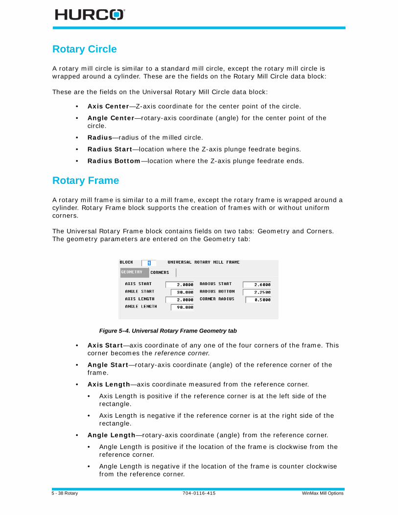
5 - 38 Rotary 704-0116-415 WinMax Mill Options
Rotary Circle
A rotary mill circle is similar to a standard mill circle, except the rotary mill circle is wrapped around a cylinder. These are the fields on the Rotary Mill Circle data block:
These are the fields on the Universal Rotary Mill Circle data block:
• Axis Center—Z-axis coordinate for the center point of the circle.
• Angle Center—rotary-axis coordinate (angle) for the center point of the circle.
• Radius—radius of the milled circle.
• Radius Start—location where the Z-axis plunge feedrate begins.
• Radius Bottom—location where the Z-axis plunge feedrate ends.
Rotary Frame
A rotary mill frame is similar to a mill frame, except the rotary frame is wrapped around a cylinder. Rotary Frame block supports the creation of frames with or without uniform corners.
The Universal Rotary Frame block contains fields on two tabs: Geometry and Corners. The geometry parameters are entered on the Geometry tab:
Figure 5–4. Universal Rotary Frame Geometry tab
• Axis Start—axis coordinate of any one of the four corners of the frame. This corner becomes the reference corner.
• Angle Start—rotary-axis coordinate (angle) of the reference corner of the frame.
• Axis Length—axis coordinate measured from the reference corner.
• Axis Length is positive if the reference corner is at the left side of the rectangle.
• Axis Length is negative if the reference corner is at the right side of the rectangle.
• Angle Length—rotary-axis coordinate (angle) from the reference corner.
• Angle Length is positive if the location of the frame is clockwise from the reference corner.
• Angle Length is negative if the location of the frame is counter clockwise from the reference corner.

WinMax Mill Options 704-0116-415 Rotary 5-39
• Radius Start—start point for the Z-axis plunge feedrate.
• Radius Bottom—end point for the Z-axis plunge feedrate.
• Corner Radius—Identifies the radius of the reference corner. Use this field if all fours corners of the frame will have the same radius. To program unique corners (with different radii), do not set a value here; instead, set the parameters on the Corners tab.
Each corner of a frame can be programmed with a radius or chamfer of a different size, on the Corners tab:
Figure 5–5. Universal Rotary Frame Corners tab
Select Line or Arc for each corner:
• Specify radius for arcs.
• Specify length and angle for lines.
Here is an example of a Rotary Frame:
Figure 5–6. Universal Rotary Frame example
Specifying a value in the Corner Radius field will reset all of the corners set as Arcs in the Corners tab to that radius. If you are creating unique corners, do not use this Corner Radius field.
If the corner should have neither, the geometry should be left as an arc with radius of 0.00, which is the default.
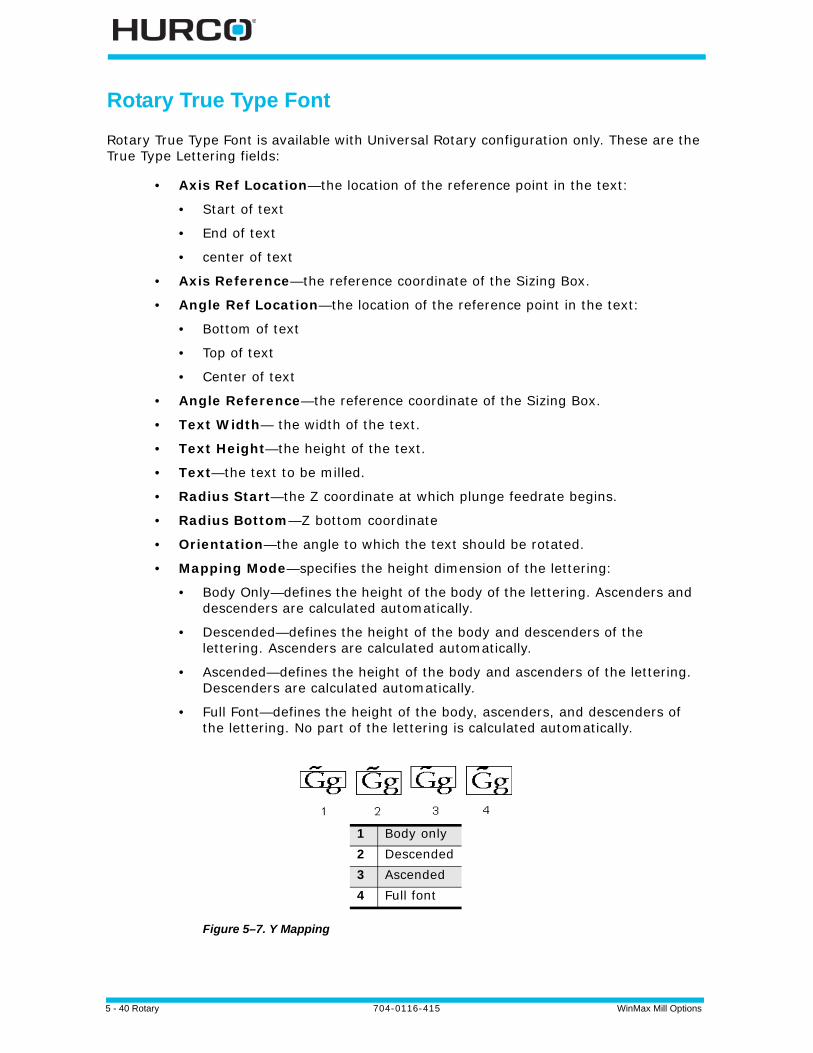
5 - 40 Rotary 704-0116-415 WinMax Mill Options
Rotary True Type Font
Rotary True Type Font is available with Universal Rotary configuration only. These are the True Type Lettering fields:
• Axis Ref Location—the location of the reference point in the text:
• Start of text
• End of text
• center of text
• Axis Reference—the reference coordinate of the Sizing Box.
• Angle Ref Location—the location of the reference point in the text:
• Bottom of text
• Top of text
• Center of text
• Angle Reference—the reference coordinate of the Sizing Box.
• Text Width— the width of the text.
• Text Height—the height of the text.
• Text—the text to be milled.
• Radius Start—the Z coordinate at which plunge feedrate begins.
• Radius Bottom—Z bottom coordinate
• Orientation—the angle to which the text should be rotated.
• Mapping Mode—specifies the height dimension of the lettering:
• Body Only—defines the height of the body of the lettering. Ascenders and descenders are calculated automatically.
• Descended—defines the height of the body and descenders of the lettering. Ascenders are calculated automatically.
• Ascended—defines the height of the body and ascenders of the lettering. Descenders are calculated automatically.
• Full Font—defines the height of the body, ascenders, and descenders of the lettering. No part of the lettering is calculated automatically.
Figure 5–7. Y Mapping
1 Body only2 Descended3 Ascended4 Full font

WinMax Mill Options 704-0116-415 Rotary 5-41
• Font—the lettering font. The font selection dialog box is opened with the Select New Font softkey, when the cursor is in the Text field.
• Outside Cylinder—specifies if text is milled on the inside or outside of a cylinder:
• Yes—text is milled on the outside of a cylinder.
• No—text is milled on the inside of a cylinder.
Rotary Slot
The Rotary Slot block creates a line or arc shape of any width on a cylinder.
See Mill Slot, on page 2 - 41 of the Conversation Part Programming manual for additional information.
Start tab
Fields on the Start tab are:
• Shape—specifies the shape of the slot, either line or arc.
• Width—indicates the width of the slot. The slot width determines how far to expand the centerline or centerarc segment programmed in the Geometry tab. Half of the programmed width is applied to each side of the line or arc.
• Axis Start—indicates the axis coordinate for the starting point of the line or arc segment.
• Angle Start—indicates the rotary-axis coordinate (angle) for the starting point of the line or arc segment.
• Radius Start—indicates the plunge feedrate start point.
• Radius Bottom—indicates the plunge bottom point.
Available Fonts for Mill True-Type Lettering
Arial (default)
Arial Black
Comic Sans MS
Courier New
Franklin Gothic Medium
Georgia
Impact
Lucida Console
Lucida Sans Unicode
Marlett
Microsoft Sans Serif
Palatino Linotype
Sylfaen
Tahoma
Times New Roman
Trebuchet MS
Verdana
Webdings
Wingdings

5 - 42 Rotary 704-0116-415 WinMax Mill Options
Geometry tab
Line geometry fields are:
• Axis End—indicates the axis end point of the line segment.
• Angle End—indicates the angle end point of the line segment.
Arc geometry fields are:
• Axis End—indicates the axis end point of the line segment.
• Angle End—indicates the angle end point of the line segment.
• Axis Center—indicates the axis center point of the arc.
• Angle Center—indicates the angle center point of the arc.
• Sweep Angle—indicates the angular distance from the start point to the end point around the center point. The range is -360° to 360°.
• Radius—indicates the distance from the center point to start and end points.
• Direction—indicates the direction of rotation from the start point to the end point around the center point.
Caps tab
Caps tab fields are:
• Start Cap—specifies the shape that is used to close the slot at the specified start point:
• Line—flat edge connects the top and bottom edges of the slot, passing through the programmed start point.
• Append Arc—rounded edge; center of semi-circle is programmed start point.
• Include Arc—rounded edge; outermost edge of semi-circle is programmed start point.
• End Cap—specifies the shape that is used to close the slot at the specified end point:
• Line—flat edge connects the top and bottom edges of the slot, passing through the programmed endpoint.
• Append Arc—rounded edge; center of semi-circle is programmed endpoint.
• Include Arc—rounded edge; outermost edge of semi-circle is programmed endpoint.
• Corner Radius—indicates the blend radius for the corners of the Start Cap or End Cap when set to Line.
Some fields may be automatically calculated when sufficient data has been entered. The CAL notation appears before the field.
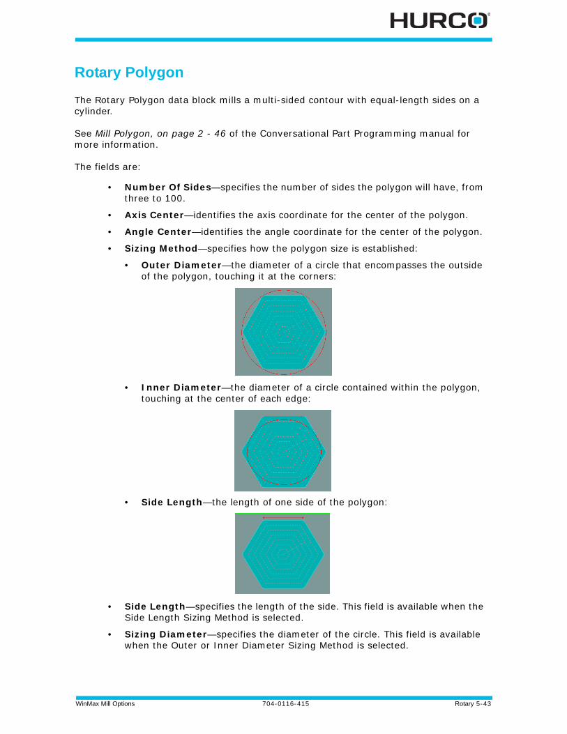
WinMax Mill Options 704-0116-415 Rotary 5-43
Rotary Polygon
The Rotary Polygon data block mills a multi-sided contour with equal-length sides on a cylinder.
See Mill Polygon, on page 2 - 46 of the Conversational Part Programming manual for more information.
The fields are:
• Number Of Sides—specifies the number of sides the polygon will have, from three to 100.
• Axis Center—identifies the axis coordinate for the center of the polygon.
• Angle Center—identifies the angle coordinate for the center of the polygon.
• Sizing Method—specifies how the polygon size is established:
• Outer Diameter—the diameter of a circle that encompasses the outside of the polygon, touching it at the corners:
• Inner Diameter—the diameter of a circle contained within the polygon, touching at the center of each edge:
• Side Length—the length of one side of the polygon:
• Side Length—specifies the length of the side. This field is available when the Side Length Sizing Method is selected.
• Sizing Diameter—specifies the diameter of the circle. This field is available when the Outer or Inner Diameter Sizing Method is selected.

5 - 44 Rotary 704-0116-415 WinMax Mill Options
• Orientation Angle—rotates the part. This field specifies an angle relative to the X axis that determines where the starting side occurs. An orientation of 0° indicates that the starting side is at the bottom of the polygon, parallel to the X axis. For example:
• Radius Start—identifies the point at which the Plunge Feedrate begins.
• Radius Bottom—identifies the point at which the Mill Feedrate begins.
• Corner Radius—identifies the radius of each corner of the polygon.
0° Angle 45° Angle
Starting Side Starting Side
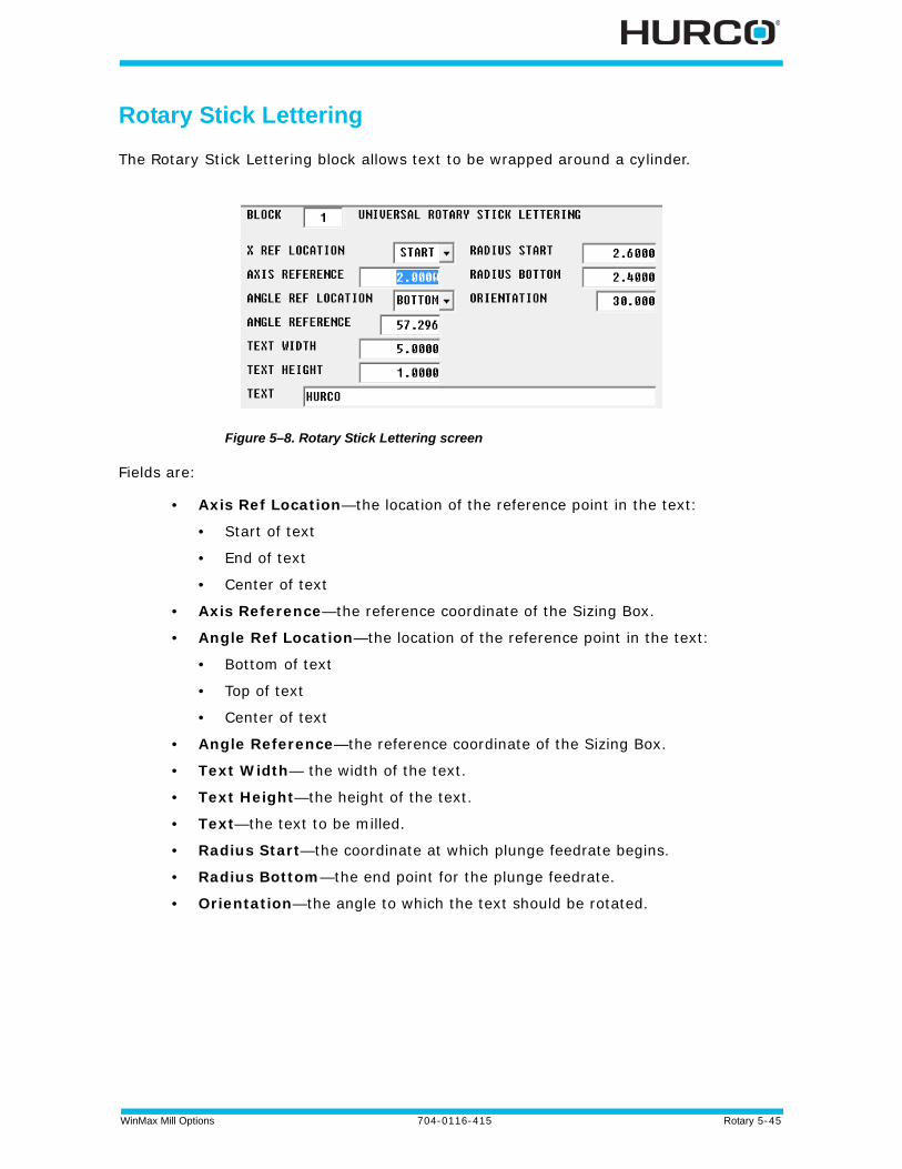
WinMax Mill Options 704-0116-415 Rotary 5-45
Rotary Stick Lettering
The Rotary Stick Lettering block allows text to be wrapped around a cylinder.
Figure 5–8. Rotary Stick Lettering screen
Fields are:
• Axis Ref Location—the location of the reference point in the text:
• Start of text
• End of text
• Center of text
• Axis Reference—the reference coordinate of the Sizing Box.
• Angle Ref Location—the location of the reference point in the text:
• Bottom of text
• Top of text
• Center of text
• Angle Reference—the reference coordinate of the Sizing Box.
• Text Width— the width of the text.
• Text Height—the height of the text.
• Text—the text to be milled.
• Radius Start—the coordinate at which plunge feedrate begins.
• Radius Bottom—the end point for the plunge feedrate.
• Orientation—the angle to which the text should be rotated.

5 - 46 Rotary 704-0116-415 WinMax Mill Options
Rotary Patterns
The Rotary Patterns data block is available with multiple rotary configurations; see Rotary Patterns, on page 5 - 12 for an explanation of the softkeys on this screen. The specific pattern data blocks for Universal Rotary are explained below.
Rotary Loop
A rotary loop defines the number and locations a mill feature will be repeated on a cylinder. The initial mill feature is located at part zero and all subsequent copies are at a specific distance along the X-A axis of the cylinder.
These are the fields on the Universal Rotary Pattern Loop data block:
• Number—total number of times the mill feature will be cut on the cylinder.
• Axis Distance—the distance on the X-axis between each repetition of the mill feature. The right-hand rule determines if Distance is positive or negative.
• Angle Distance—the distance (angle) on the rotary-axis between each repetition of the mill feature.
A rotary Pattern End data block is required to end the sequence repeated in the Rotary Pattern Loop data block.
Rotary pattern and standard pattern data blocks can be nested (i.e., entirely contained within another pattern). The order of execution for nested rotary pattern and standard pattern data blocks is from the inside to the outside.
This is an example of nested data blocks in a program (the indentations are used illustrate the order of execution; your Conversational part program will not have these indentations).
In the following example, this is the order of execution:
1. Holes and rotary Mill Frame operations contained within the Pattern Loop Rotate data block.
2. Standard Mill Circle operation contained within the Rotary Pattern Loop data block.
Rotary Pattern Loop Standard Mill Circle (or any other rotary or non-rotary data blocks) Pattern Loop Rotate Holes operation Rotary Mill Frame (or other rotary or non-rotary data blocks) Pattern End (ends the Pattern Loop Rotate) Pattern End (ends the Rotary Pattern Loop)
Only one Rotary Position data block is required for nested Rotary Pattern Loop data blocks.
WinMax Mill Options 704-0116-415 Rotary 5-47
Rotary Locations
The Rotary Pattern Locations data block is used to create a list of locations of a mill feature repeated on a cylinder. Up to 999 copies can be located anywhere on the part.
Each set of locations listed on the Rotary Patterns Location data block is a specific location on the cylinder, relative to part zero. If you want the mill feature to be cut at part zero, you must define the coordinates of part zero in one of the sets of locations.
These are the fields on the Universal Rotary Pattern Locations data block:
• Axis—Axis coordinate where the mill feature will be located on the part.
• Angle—Angle coordinate where the mill feature will be located on the part.
Rotary Rectangular
Rotary Rectangular Pattern Block is available only with the Universal Rotary configuration. Fields are:
• Axis Number—the number of times the programmed routine will be repeated along a line parallel to the rotary axis.
• Angle Number—the number of times the programmed routine will be repeated along the rotary axis.
• Axis Distance—the distance between the patterns parallel to the rotary axis.
• Angle Distance—the distance between the patterns along the rotary axis.
Rotary Mirror
Rotary Mirror Pattern Block is available only with the Universal Rotary configuration. Fields are:
• Keep Original—indicate if you want to machine the original pattern in addition to the mirrored pattern.
• Yes—machine original pattern
• No—machine only mirrored pattern
• Cylinder Angle—the coordinate of a point on the mirror line.
• Cylinder Axis—the coordinate of a point on the mirror line.
• Angle—the orientation of the mirror line which passes through the point defined above (measured in XY from 3 o’clock).
A rotary Pattern End data block is required to end the sequence in the Rotary Pattern Locations data block.
After the rotary Pattern End data block has executed, the orientation of the machine axes will remain at the position defined in the most recent Rotary Position data block.
If the part program continues beyond the Rotary Pattern operation, another Rotary Position data block will be required if the axes must be reoriented to a different position.

5 - 48 Rotary 704-0116-415 WinMax Mill Options
Rotary Transform Plane
Transform Plane is used in a Conversational rotary program to position part zero for a non-rotary data block to any orientation of any plane of your rotary- or tilt-axis machine. For example, use Transform Plane when you want to repeat a non-rotary feature (e.g., mill contour, holes) on multiple sides of a part.
Rotary Transform Plane End
The Transform Plane End block ends the Transform Plane operation.
After the Transform Plane End data block has executed, the orientation of the part will remain at the position defined in the most recent Rotary Position data block.
If the part program continues beyond the Transform Plane operation, another Rotary Position data block will be required if the part must be reorientated to a different position.
Pattern End
A Pattern End data block is required to end rotary Pattern Loop and rotary Pattern Locations operations. There are no fields in the Pattern End data block.
Rotary Parameters
The Rotary Orientation field defines the axis configuration: Rotary A/AB, Rotary B, Rotary AC, Rotary BC, and User Defined. User Defined orientation requires the Axis of Rotation (Cylinder Axis vector) and Zero Angle vector. The Zero Angle vector describes the zero-degree Cylindrical Point vector direction with respect to the current coordinate system. These vectors must be perpendicular otherwise the control will throw an error. Other Rotary Orientation selections (Rotary A/AB, Rotary B, Rotary AC, Rotary BC) are available to automatically configure the Axis of Rotation and Zero Angle vectors to describe rotary features for Hurco's current program type configurations.
After the rotary Pattern End data block has executed, the orientation of the machine axes will remain at the position defined in the most recent Rotary Position data block.
If the part program continues beyond the Rotary Pattern operation, another Rotary Position data block will be required if the axes must be reoriented to a different position.
• A Rotary Pattern Loop data block only modifies the rotary operations contained within the pattern.
• The subsequent Rotary Position data block defines the orientation of the machine axes after the pattern is executed, and can provide a reference point if Recovery Restart is used.
• If the Rotary Pattern End data block is the last data block of the part program, a subsequent Rotary Position data block is not necessary.
• If a non-rotary operation data block (e.g., holes operation) is used in a rotary loop, a Rotary Position data block is required before the non-rotary operation data block to position the axes before the operation is executed in the loop.

WinMax Mill Options 704-0116-415 Rotary 5-49
Calculating X- and Z-Axis Positions After a Tilt-Axis Move
The initial location of a point on a cylindrical workpiece will be at different X and Z coordinates after the tilt-axis is moved into position. Some tilt-axis tables have part zero calibrated at 0° vertical, and some have part zero calibrated at 0° horizontal. Use the formulas below that correspond to the part zero calibration of your machine.
Part Zero Calibrated at Zero Degree Vertical
Follow these steps to determine the relative location of X and Z when the tilt-axis is positioned at 0° in the vertical plane (as shown in the figure below):
1. Use the formula L = Z1-Z3 to calculate L, the distance between the point’s initial location and the location of the same point after the workpiece is positioned to a known angle on the tilt-axis.
2. Use the formula X2 = L sinB to determine the location of X2, the location of the X coordinate on the workpiece after the tilt-axis has been moved.
3. Use the formula Z2 = L - (L cosB) to determine Z2, the location of the Z coordinate on the workpiece after the tilt-axis has been moved.
Figure 5–9. Vertical Tilt-Axis Example
1 Z1
2 Z2
3 B (tilt-axis) = 0°
4 Z3
5 L
6 X2

5 - 50 Rotary 704-0116-415 WinMax Mill Options
Part Zero Calibrated at Zero Degree Horizontal
Follow these steps to determine the relative location of X and Z when the tilt-axis is positioned at 0º in the horizontal plane (as shown in the figure below).
1. Use the formula L = X1-X3 to calculate L, the distance between the point’s initial location and the location of the same point after the workpiece is positioned to a known angle on the tilt-axis.
2. Use the formula X2 = L- (L cosB) to determine the location of X2, the location of the X coordinate on the workpiece after the tilt-axis has been moved.
3. Use the formula Z2 = L sinB to determine the location of Z2, the location of the Z coordinate on the workpiece after the tilt-axis has been moved.
Figure 5–10. Horizontal Tilt-Axis Example
1 X1
2 X2
3 B (tilt-axis) = 0°
4 X3
5 L
6 Z2
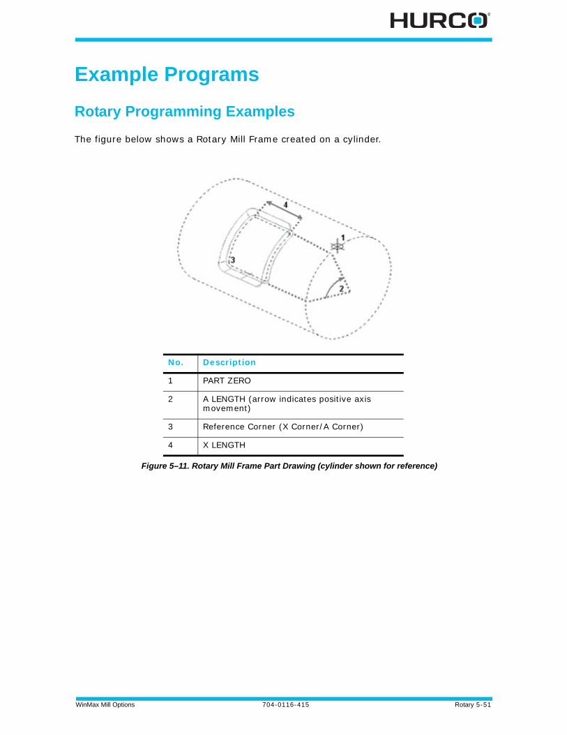
WinMax Mill Options 704-0116-415 Rotary 5-51
Example Programs
Rotary Programming Examples
The figure below shows a Rotary Mill Frame created on a cylinder.
Figure 5–11. Rotary Mill Frame Part Drawing (cylinder shown for reference)
No. Description
1 PART ZERO
2 A LENGTH (arrow indicates positive axis movement)
3 Reference Corner (X Corner/A Corner)
4 X LENGTH
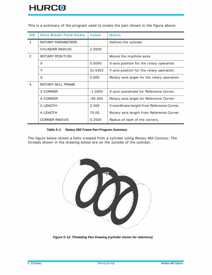
5 - 52 Rotary 704-0116-415 WinMax Mill Options
This is a summary of the program used to create the part shown in the figure above:
Table 5–1. Rotary Mill Frame Part Program Summary
The figure below shows a helix created from a cylinder using Rotary Mill Contour. The threads shown in the drawing below are on the outside of the cylinder.
Figure 5–12. Threading Part Drawing (cylinder shown for reference)
DB Data Block/Field Name Value Notes
1 ROTARY PARAMETERS Defines the cylinder.
CYLINDER RADIUS 2.0000
2 ROTARY POSITION Moves the machine axes.
X 0.0000 X-axis position for the rotary operation.
Y 31.0352 Y-axis position for the rotary operation.
A 0.000 Rotary-axis angle for the rotary operation.
3 ROTARY MILL FRAME
X CORNER -1.0000 X-axis coordinate for Reference Corner.
A CORNER -90.000 Rotary-axis angle for Reference Corner.
X LENGTH 2.000 X coordinate length from Reference Corner.
A LENGTH 75.00 Rotary-axis length from Reference Corner.
CORNER RADIUS 0.2500 Radius of each of the corners.
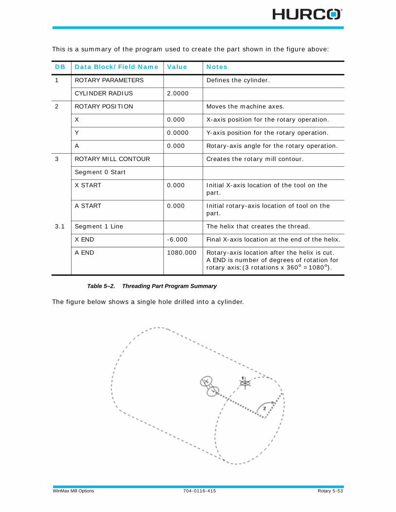
WinMax Mill Options 704-0116-415 Rotary 5-53
This is a summary of the program used to create the part shown in the figure above:
Table 5–2. Threading Part Program Summary
The figure below shows a single hole drilled into a cylinder.
DB Data Block/Field Name Value Notes
1 ROTARY PARAMETERS Defines the cylinder.
CYLINDER RADIUS 2.0000
2 ROTARY POSITION Moves the machine axes.
X 0.000 X-axis position for the rotary operation.
Y 0.0000 Y-axis position for the rotary operation.
A 0.000 Rotary-axis angle for the rotary operation.
3 ROTARY MILL CONTOUR Creates the rotary mill contour.
Segment 0 Start
X START 0.000 Initial X-axis location of the tool on the part.
A START 0.000 Initial rotary-axis location of tool on the part.
3.1 Segment 1 Line The helix that creates the thread.
X END -6.000 Final X-axis location at the end of the helix.
A END 1080.000 Rotary-axis location after the helix is cut. A END is number of degrees of rotation for rotary axis:(3 rotations x 360° =1080°).
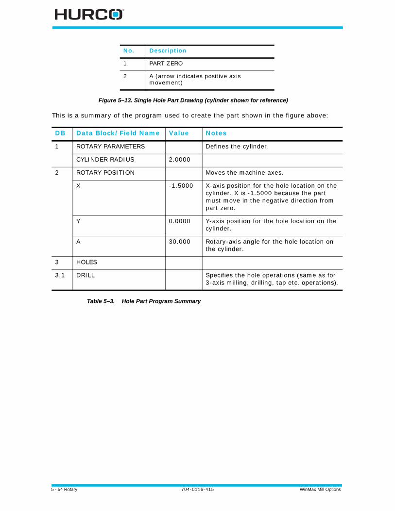
5 - 54 Rotary 704-0116-415 WinMax Mill Options
Figure 5–13. Single Hole Part Drawing (cylinder shown for reference)
This is a summary of the program used to create the part shown in the figure above:
Table 5–3. Hole Part Program Summary
No. Description
1 PART ZERO
2 A (arrow indicates positive axis movement)
DB Data Block/Field Name Value Notes
1 ROTARY PARAMETERS Defines the cylinder.
CYLINDER RADIUS 2.0000
2 ROTARY POSITION Moves the machine axes.
X -1.5000 X-axis position for the hole location on the cylinder. X is -1.5000 because the part must move in the negative direction from part zero.
Y 0.0000 Y-axis position for the hole location on the cylinder.
A 30.000 Rotary-axis angle for the hole location on the cylinder.
3 HOLES
3.1 DRILL Specifies the hole operations (same as for 3-axis milling, drilling, tap etc. operations).

WinMax Mill Options 704-0116-415 Rotary 5-55
The figure below shows a pattern of holes on a cylinder created with a Rotary Pattern Loop.
Figure 5–14. Rotary Pattern Loop Part Drawing (cylinder shown for reference)
No. Description
1 PART ZERO
2 A DISTANCE (arrow indicates positive axis movement)
3 X DISTANCE
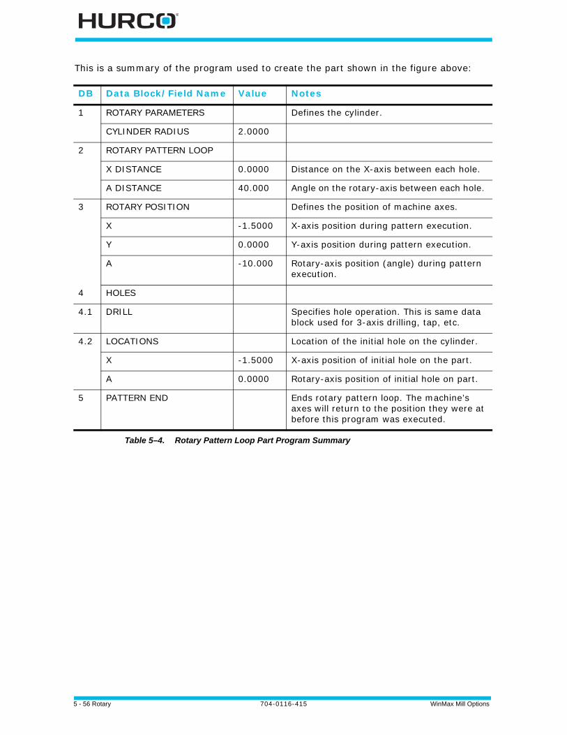
5 - 56 Rotary 704-0116-415 WinMax Mill Options
This is a summary of the program used to create the part shown in the figure above:
Table 5–4. Rotary Pattern Loop Part Program Summary
DB Data Block/Field Name Value Notes
1 ROTARY PARAMETERS Defines the cylinder.
CYLINDER RADIUS 2.0000
2 ROTARY PATTERN LOOP
X DISTANCE 0.0000 Distance on the X-axis between each hole.
A DISTANCE 40.000 Angle on the rotary-axis between each hole.
3 ROTARY POSITION Defines the position of machine axes.
X -1.5000 X-axis position during pattern execution.
Y 0.0000 Y-axis position during pattern execution.
A -10.000 Rotary-axis position (angle) during pattern execution.
4 HOLES
4.1 DRILL Specifies hole operation. This is same data block used for 3-axis drilling, tap, etc.
4.2 LOCATIONS Location of the initial hole on the cylinder.
X -1.5000 X-axis position of initial hole on the part.
A 0.0000 Rotary-axis position of initial hole on part.
5 PATTERN END Ends rotary pattern loop. The machine’s axes will return to the position they were at before this program was executed.
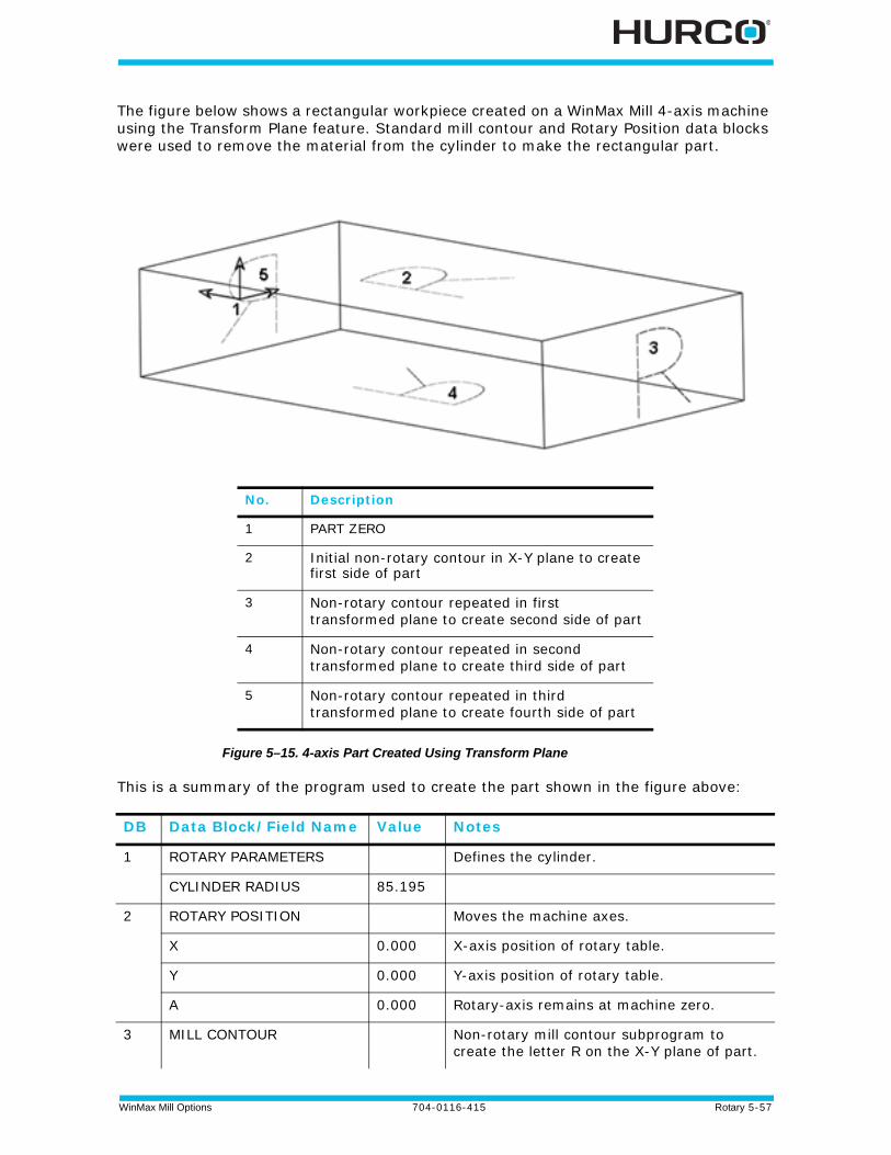
WinMax Mill Options 704-0116-415 Rotary 5-57
The figure below shows a rectangular workpiece created on a WinMax Mill 4-axis machine using the Transform Plane feature. Standard mill contour and Rotary Position data blocks were used to remove the material from the cylinder to make the rectangular part.
Figure 5–15. 4-axis Part Created Using Transform Plane
This is a summary of the program used to create the part shown in the figure above:
No. Description
1 PART ZERO
2 Initial non-rotary contour in X-Y plane to create first side of part
3 Non-rotary contour repeated in first transformed plane to create second side of part
4 Non-rotary contour repeated in second transformed plane to create third side of part
5 Non-rotary contour repeated in third transformed plane to create fourth side of part
DB Data Block/Field Name Value Notes
1 ROTARY PARAMETERS Defines the cylinder.
CYLINDER RADIUS 85.195
2 ROTARY POSITION Moves the machine axes.
X 0.000 X-axis position of rotary table.
Y 0.000 Y-axis position of rotary table.
A 0.000 Rotary-axis remains at machine zero.
3 MILL CONTOUR Non-rotary mill contour subprogram to create the letter R on the X-Y plane of part.
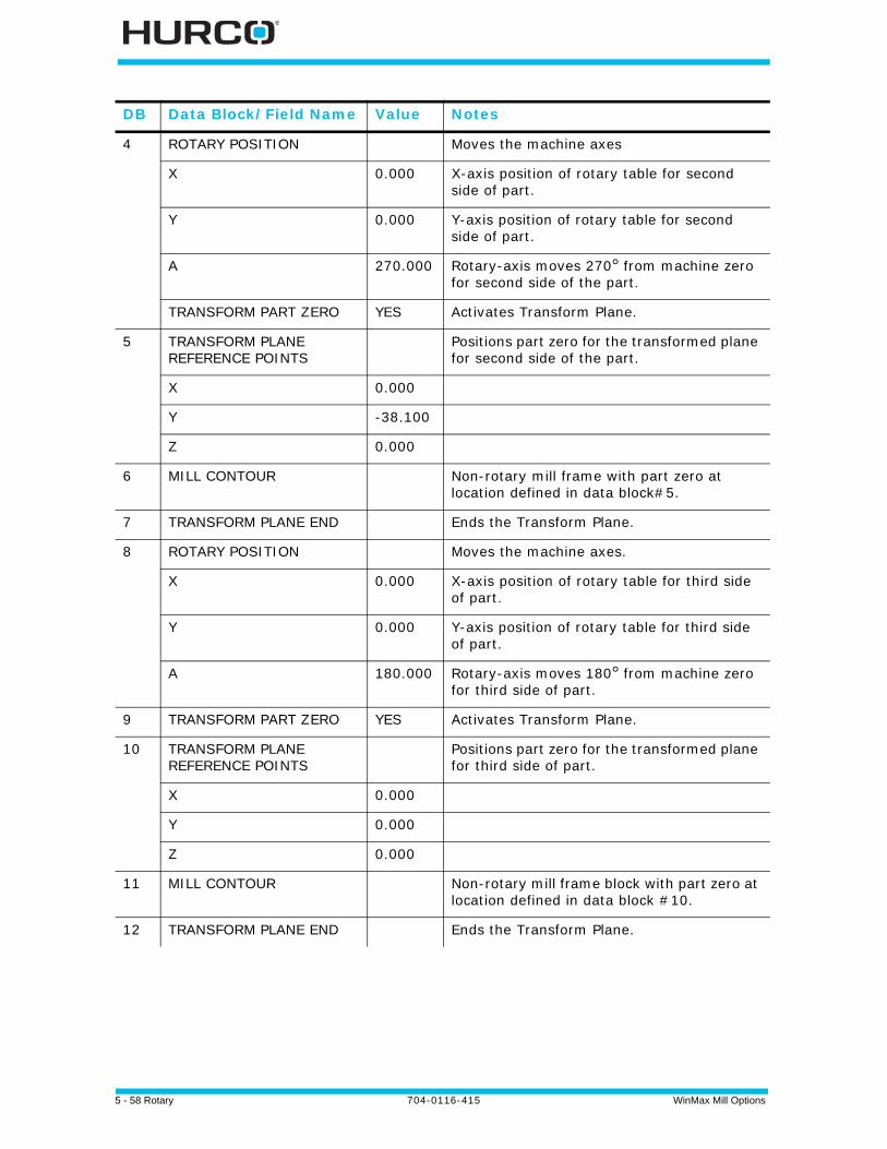
5 - 58 Rotary 704-0116-415 WinMax Mill Options
DB Data Block/Field Name Value Notes
4 ROTARY POSITION Moves the machine axes
X 0.000 X-axis position of rotary table for second side of part.
Y 0.000 Y-axis position of rotary table for second side of part.
A 270.000 Rotary-axis moves 270° from machine zero for second side of the part.
TRANSFORM PART ZERO YES Activates Transform Plane.
5 TRANSFORM PLANE REFERENCE POINTS
Positions part zero for the transformed plane for second side of the part.
X 0.000
Y -38.100
Z 0.000
6 MILL CONTOUR Non-rotary mill frame with part zero at location defined in data block#5.
7 TRANSFORM PLANE END Ends the Transform Plane.
8 ROTARY POSITION Moves the machine axes.
X 0.000 X-axis position of rotary table for third side of part.
Y 0.000 Y-axis position of rotary table for third side of part.
A 180.000 Rotary-axis moves 180° from machine zero for third side of part.
9 TRANSFORM PART ZERO YES Activates Transform Plane.
10 TRANSFORM PLANE REFERENCE POINTS
Positions part zero for the transformed plane for third side of part.
X 0.000
Y 0.000
Z 0.000
11 MILL CONTOUR Non-rotary mill frame block with part zero at location defined in data block #10.
12 TRANSFORM PLANE END Ends the Transform Plane.

WinMax Mill Options 704-0116-415 Rotary 5-59
Table 5–5. 4-Axis Transform Plane Program Summary
DB Data Block/Field Name Value Notes
13 ROTARY POSITION Moves the machine axes.
X 0.000 X-axis position of rotary table for final side of part.
Y 0.000 Y-axis position of rotary table for final side of part.
A 90.000 Rotary-axis position at 90° from machine zero for final side of part.
TRANSFORM PART ZERO YES Activates Transform Plane.
14 TRANSFORM PLANE REFERENCE POINTS
Positions part zero for the transformed plane for final side of part.
X 0.000
Y 38.100
Z 0.000
15 PATTERN LOOP ROTATE
16 MILL CONTOUR Non-rotary mill frame block with part zero at location defined in data block #14.
17 PATTERN END Ends the Pattern Loop Rotate operation.
18 TRANSFORM PLANE END Ends the Transform Plane.
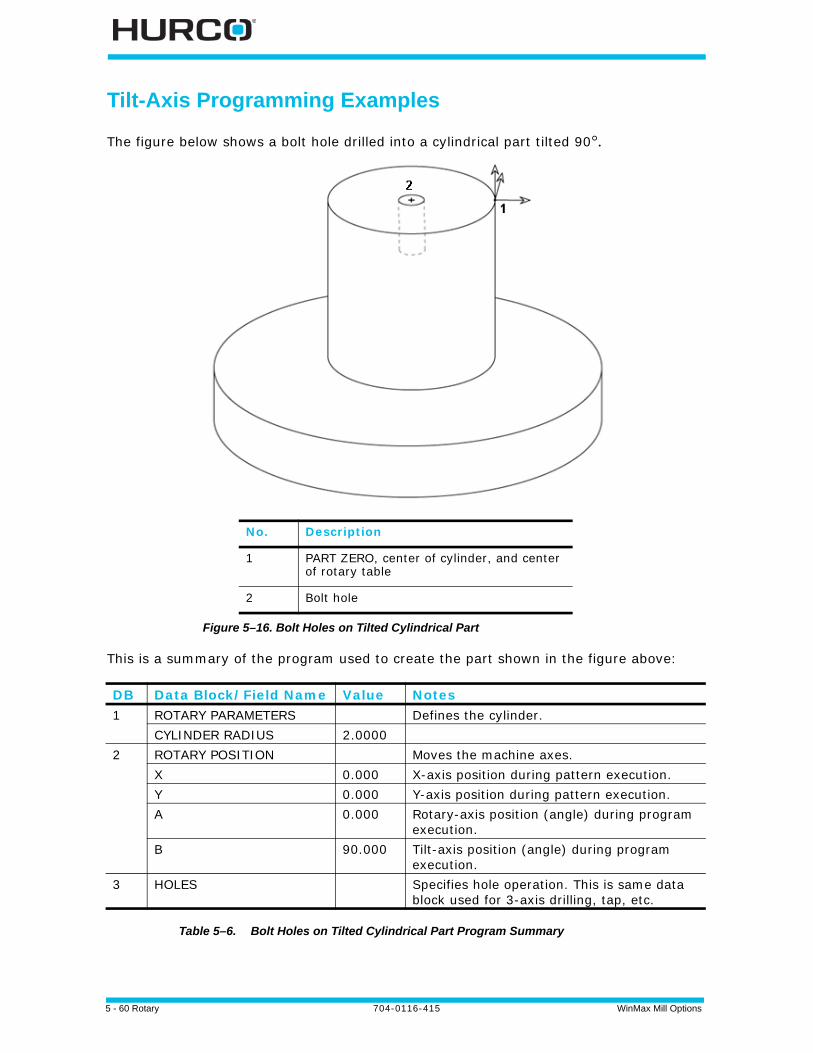
5 - 60 Rotary 704-0116-415 WinMax Mill Options
Tilt-Axis Programming Examples
The figure below shows a bolt hole drilled into a cylindrical part tilted 90°.
Figure 5–16. Bolt Holes on Tilted Cylindrical Part
This is a summary of the program used to create the part shown in the figure above:
Table 5–6. Bolt Holes on Tilted Cylindrical Part Program Summary
No. Description
1 PART ZERO, center of cylinder, and center of rotary table
2 Bolt hole
DB Data Block/Field Name Value Notes1 ROTARY PARAMETERS Defines the cylinder.
CYLINDER RADIUS 2.00002 ROTARY POSITION Moves the machine axes.
X 0.000 X-axis position during pattern execution.Y 0.000 Y-axis position during pattern execution.A 0.000 Rotary-axis position (angle) during program
execution.B 90.000 Tilt-axis position (angle) during program
execution.3 HOLES Specifies hole operation. This is same data
block used for 3-axis drilling, tap, etc.
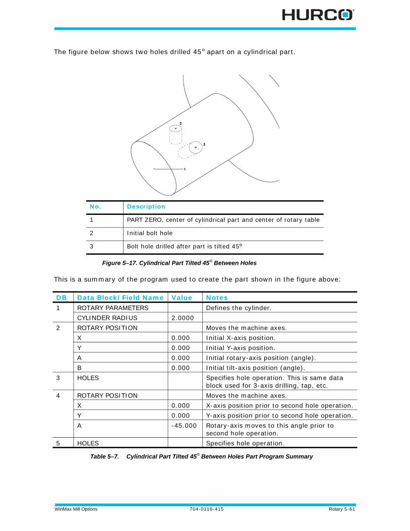
WinMax Mill Options 704-0116-415 Rotary 5-61
The figure below shows two holes drilled 45° apart on a cylindrical part.
Figure 5–17. Cylindrical Part Tilted 45° Between Holes
This is a summary of the program used to create the part shown in the figure above:
Table 5–7. Cylindrical Part Tilted 45° Between Holes Part Program Summary
No. Description
1 PART ZERO, center of cylindrical part and center of rotary table
2 Initial bolt hole
3 Bolt hole drilled after part is tilted 45º
DB Data Block/Field Name Value Notes1 ROTARY PARAMETERS Defines the cylinder.
CYLINDER RADIUS 2.00002 ROTARY POSITION Moves the machine axes.
X 0.000 Initial X-axis position.Y 0.000 Initial Y-axis position.A 0.000 Initial rotary-axis position (angle).B 0.000 Initial tilt-axis position (angle).
3 HOLES Specifies hole operation. This is same data block used for 3-axis drilling, tap, etc.
4 ROTARY POSITION Moves the machine axes.X 0.000 X-axis position prior to second hole operation.Y 0.000 Y-axis position prior to second hole operation.A -45.000 Rotary-axis moves to this angle prior to
second hole operation.5 HOLES Specifies hole operation.
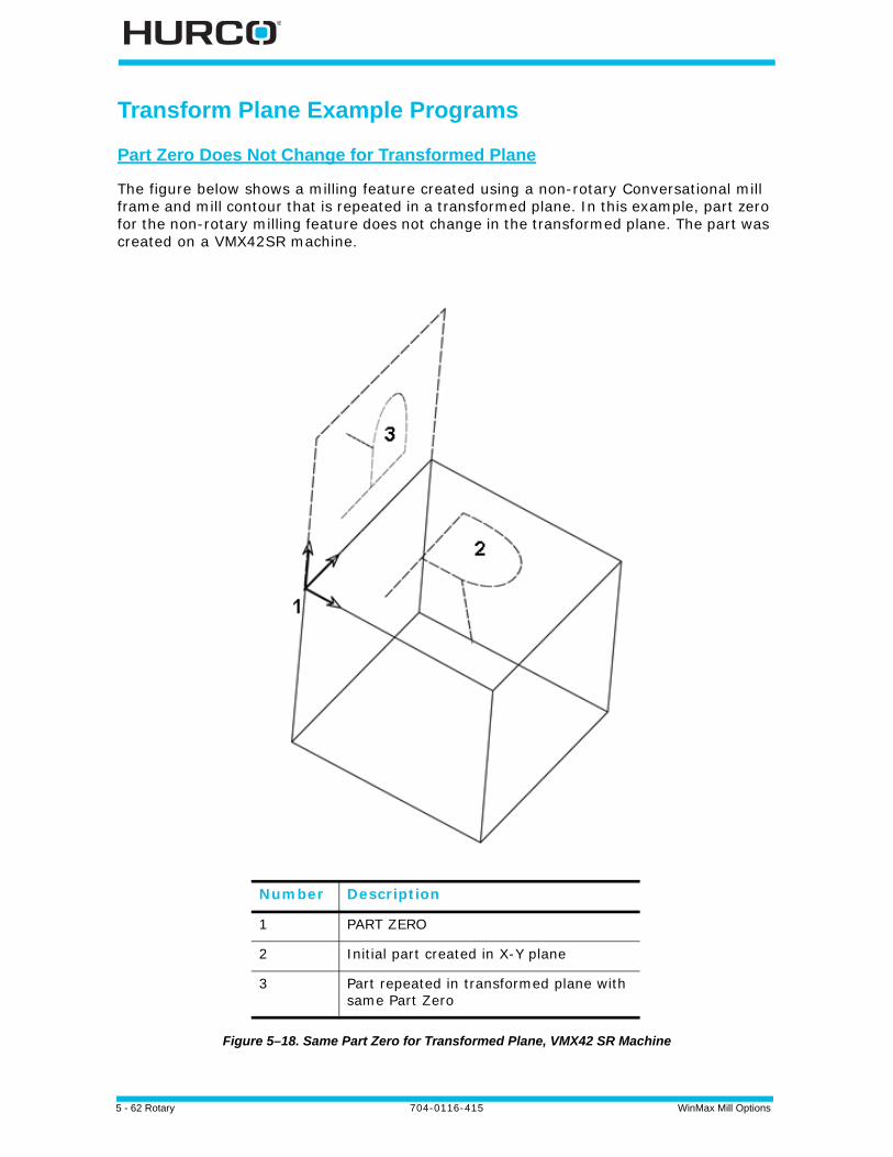
5 - 62 Rotary 704-0116-415 WinMax Mill Options
Transform Plane Example Programs
Part Zero Does Not Change for Transformed Plane
The figure below shows a milling feature created using a non-rotary Conversational mill frame and mill contour that is repeated in a transformed plane. In this example, part zero for the non-rotary milling feature does not change in the transformed plane. The part was created on a VMX42SR machine.
Figure 5–18. Same Part Zero for Transformed Plane, VMX42 SR Machine
Number Description
1 PART ZERO
2 Initial part created in X-Y plane
3 Part repeated in transformed plane with same Part Zero

WinMax Mill Options 704-0116-415 Rotary 5-63
This is a summary of the program used to create the part in the figure above:
Table 5–8. Same Part Zero for Transformed Plane Part Program Summary, VMX42SR Machine
DB Data Block/Field Name Value Notes
1 ROTARY POSITION Defines the position of all machine axes.
X 0.0000 X-axis positioning of rotary-axis table.
Y 0.0000 Y-axis positioning of rotary-axis table.
B 0.0000 B-axis positioning at 0° from machine zero.
C 0.0000 C-axis positioning at 0° from machine zero.
TRANSFORM PART ZERO No Transform Plane not activated.
2 MILL CONTOUR Non-rotary mill contour subprogram to create an R on the X-Y plane of part.
3 ROTARY POSITION Defines the position of all machine axes.
X 0.0000 X-axis move prior to positioning rotary-axis table for Transform Plane operation.
Y 0.0000 Y-axis move prior to positioning rotary-axis table for Transform Plane operation.
B -90.00 B-axis will move -90° from machine zero for transformed plane.
C 0.0000 C-axis will move 0° from machine zero for transformed plane.
TRANSFORM PART ZERO YES Activates Transform Plane.
4 TRANSFORM PLANE REFERENCE POINTS
Positions part zero for the transformed plane. For this program, part zero for the transformed plane is the same as initial part zero.
X 0.000
Y 0.000
Z 0.000
5 MILL CONTOUR Non-rotary mill contour with part zero at location defined in data block#4.
6 TRANSFORM PLANE END Ends the Transform Plane in data block #5.
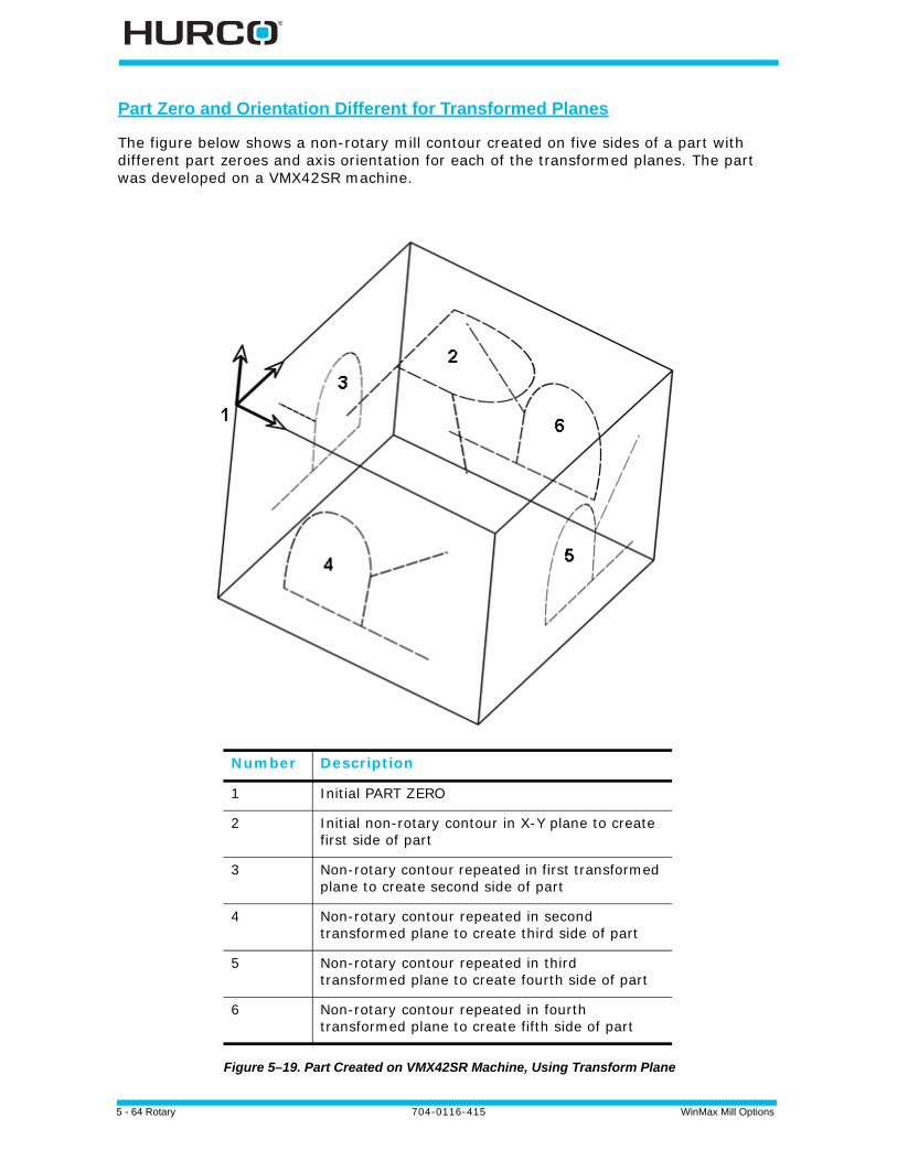
5 - 64 Rotary 704-0116-415 WinMax Mill Options
Part Zero and Orientation Different for Transformed Planes
The figure below shows a non-rotary mill contour created on five sides of a part with different part zeroes and axis orientation for each of the transformed planes. The part was developed on a VMX42SR machine.
Figure 5–19. Part Created on VMX42SR Machine, Using Transform Plane
Number Description
1 Initial PART ZERO
2 Initial non-rotary contour in X-Y plane to create first side of part
3 Non-rotary contour repeated in first transformed plane to create second side of part
4 Non-rotary contour repeated in second transformed plane to create third side of part
5 Non-rotary contour repeated in third transformed plane to create fourth side of part
6 Non-rotary contour repeated in fourth transformed plane to create fifth side of part
WinMax Mill Options 704-0116-415 Rotary 5-65
This is a summary of the program used to create the part shown in the figure above:
DB Data Block/Field Name Value Notes
1 ROTARY POSITION Defines position of machine axes.
X 0.0000
Y 0.0000
B 0.0000 Tilt-axis will move 0° from machine zero.
C 0.0000 Rotary-axis will move 0° from machine zero.
TRANSFORM PART ZERO NO Transform Plane not activated.
2 MILL CONTOUR Non-rotary mill contour to create the letter R on the X-Y plane of the part.
3 ROTARY POSITION Redefines position of machine axes.
X 0.0000 X-axis move prior to positioning rotary table for Transform Plane operation.
Y 0.0000 Y-axis move prior to positioning rotary table for Transform Plane operation.
B -90.000 Tilt-axis will move -90° from machine zero for Transform Plane operation.
C 0.0000 Rotary-axis will move 0° from machine zero for Transform Plane operation.
TRANSFORM PART ZERO YES Activates Transform Plane.
4 TRANSFORM PLANE Repositions part zero on transformed plane (i.e., second side of cube).
X 0.000
Y 0.000
Z -100.000
5 MILL CONTOUR Non-rotary mill contour with part zero repositioned at location in data block #4.
6 TRANSFORM PLANE END Ends Transform Plane.

5 - 66 Rotary 704-0116-415 WinMax Mill Options
DB Data Block/Field Name Value Notes
7 ROTARY POSITION Redefines position of machine axes.
X 0.000 X-axis move prior to positioning rotary table for Transform Plane operation.
Y 0.000 Y-axis move prior to positioning rotary table for Transform Plane operation.
B -90.000 Tilt-axis remains at -90° from machine zero for Transform Plane operation.
C 90.000 Rotary-axis moves 90° from machine zero for Transform Plane operation.
TRANSFORM PART ZERO YES Activates Transform Plane.
8 TRANSFORM PLANE Repositions part zero for transformed plane (i.e., third side of cube).
X 100.000
Y 0.000
Z -100.000
9 MILL CONTOUR Non-rotary mill contour with part zero repositioned at location in data block #8.
10 TRANSFORM PLANE END Ends Transform Plane.
11 ROTARY POSITION Redefines position of machine axes.
X 0.0000 X-axis move prior to positioning rotary table for Transform Plane operation.
Y 0.0000 Y-axis move prior to positioning rotary table for Transform Plane operation.
B -90.000 Tilt-axis will move -90° from machine zero for Transform Plane operation.
C 180.000 Rotary-axis will move 180° from machine zero for Transform Plane operation.
TRANSFORM PART ZERO YES Activates Transform Plane.
12 TRANSFORM PLANE Repositions part zero on transformed plane (i.e., fourth side of cube).
X 100.000
Y 100.000
Z -100.000
13 MILL CONTOUR Non-rotary mill contour with part zero repositioned at location in data block #12.
14 TRANSFORM PLANE END Ends Transform Plane.

WinMax Mill Options 704-0116-415 Post Processor (Desktop Only) 6-1
POST PROCESSOR (DESKTOP ONLY)
The Post Processor option allows Conversational part programs to be converted to NC (M and G code) programs, using third-party Post Processor software.
To convert a program, select the Post Processor icon on the Utilities screen:
Figure 6–1. Utilities screen with Post Processor softkey
The Post Processor Configuration screen appears:
Figure 6–2. Post Processor Configuration screen

6 - 2 Post Processor (Desktop Only) 704-0116-415 WinMax Mill Options
The fields on the Post Processor Configuration screen are:
• Output Arcs As—specify if arcs should be output as arc interpolation commands or a series of lines.
• Output Canned Cycles As—specify if canned cycles should be output as canned cycle commands or as a series of lines.
• Output Tool Path As—specify if tool paths are output as centerline data (no G41 or G42) or as part surfaces with cutter compensation.
• Display APT Fields in Editor—specify Yes or No to display APT fields in the NC Editor.
• APT Output Units—specify the units fort he APT data output: inches, millimeters, or Program Output (units selected in Program Properties).
Select the Post to NC softkey. The Post to file dialog opens:
Specify the location to save the file in the Post to File field. Click on the folder button to browse for the location. Choose the control type using the drop-down menu in the Control Type field. Click OK to post the file.
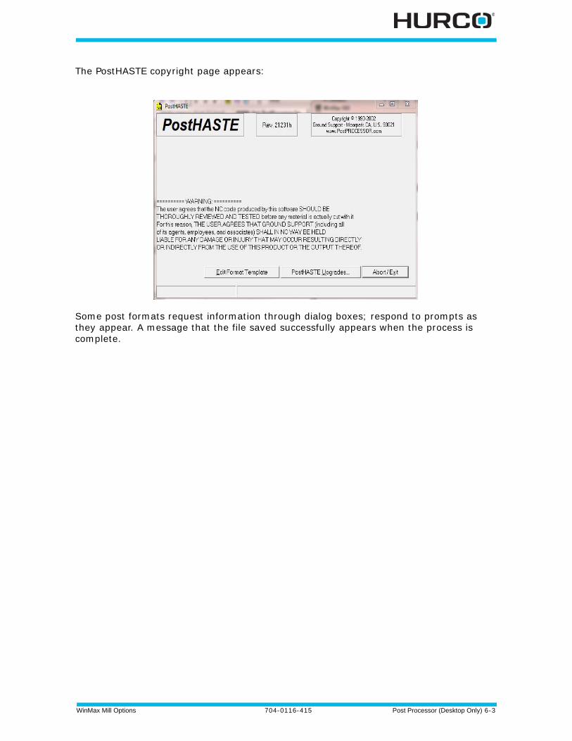
WinMax Mill Options 704-0116-415 Post Processor (Desktop Only) 6-3
The PostHASTE copyright page appears:
Some post formats request information through dialog boxes; respond to prompts as they appear. A message that the file saved successfully appears when the process is complete.

6 - 4 Post Processor (Desktop Only) 704-0116-415 WinMax Mill Options
WinMax Mill Options 704-0116-415 Part Probing Option 7-1
PART PROBING OPTION
Part probing is used during Part Setup to probe the part’s edge, corner, bore, boss, rectangular pocket, or rectangular solid. The probe collects information about the part’s center position and diameter. This information is used to set Part Zero, making part setup faster and more accurate. Part probing can be used in Manual or Auto mode and with either Conversational or NC programming. Part probing can also be used for part quality verification.
Manual Mode
Probing in Manual Mode is used to set part zero and/or determine skew:
1. Enter information about the probe in Part Probe Parameters. See Part Setup—Part Probe Parameters, on page 7 - 2.
2. Calibrate the probe and enter the deflection offsets. See Part Probe Calibration and Cycles, on page 7 - 5.
3. Select the cycle and probe the part. See Manual Mode Part Setup Probing Cycles , on page 7 - 13 and/or Manual Mode Part Skew Probing Cycles , on page 7 - 35.
Auto Mode
Probing in Auto Mode is used to set part zero and/or determine skew within the part program (rather than in Part Setup as in Manual Mode). It can also be used to gather data about part quality.
1. Enter information about the probe in Part Probe Parameters. See Part Setup—Part Probe Parameters, on page 7 - 2.
2. Calibrate the probe and enter the deflection offsets. See Part Probe Calibration and Cycles, on page 7 - 5.
3. Probe the part to set part zero and/or determine skew. This is done within the program; see Automatic Mode, on page 7 - 42.
Additionally, part inspection is performed in Auto Mode. See Part Quality Verification, on page 7 - 46.
It is the operator’s responsibility to set safe travel limits for the part probe as described in this chapter.
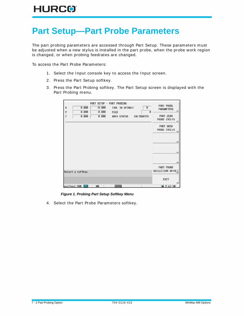
7 - 2 Part Probing Option 704-0116-415 WinMax Mill Options
Part Setup—Part Probe Parameters
The part probing parameters are accessed through Part Setup. These parameters must be adjusted when a new stylus is installed in the part probe, when the probe work region is changed, or when probing feedrates are changed.
To access the Part Probe Parameters:
1. Select the Input console key to access the Input screen.
2. Press the Part Setup softkey.
3. Press the Part Probing softkey. The Part Setup screen is displayed with the Part Probing menu.
Figure 1. Probing Part Setup Softkey Menu
4. Select the Part Probe Parameters softkey.
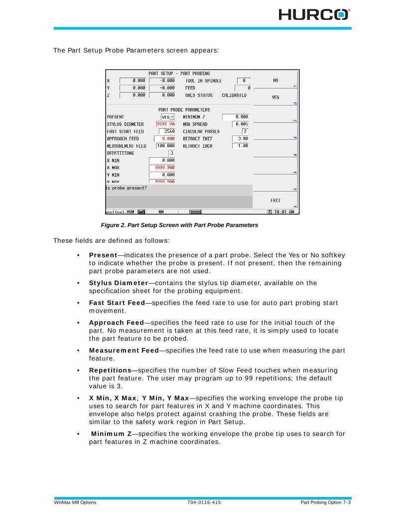
WinMax Mill Options 704-0116-415 Part Probing Option 7-3
The Part Setup Probe Parameters screen appears:
Figure 2. Part Setup Screen with Part Probe Parameters
These fields are defined as follows:
• Present—indicates the presence of a part probe. Select the Yes or No softkey to indicate whether the probe is present. If not present, then the remaining part probe parameters are not used.
• Stylus Diameter—contains the stylus tip diameter, available on the specification sheet for the probing equipment.
• Fast Start Feed—specifies the feed rate to use for auto part probing start movement.
• Approach Feed—specifies the feed rate to use for the initial touch of the part. No measurement is taken at this feed rate, it is simply used to locate the part feature to be probed.
• Measurement Feed—specifies the feed rate to use when measuring the part feature.
• Repetitions—specifies the number of Slow Feed touches when measuring the part feature. The user may program up to 99 repetitions; the default value is 3.
• X Min, X Max; Y Min, Y Max—specifies the working envelope the probe tip uses to search for part features in X and Y machine coordinates. This envelope also helps protect against crashing the probe. These fields are similar to the safety work region in Part Setup.
• Minimum Z—specifies the working envelope the probe tip uses to search for part features in Z machine coordinates.
7 - 4 Part Probing Option 704-0116-415 WinMax Mill Options
• Max Spread—the deviation (difference) between the minimum and maximum probe readings. If the deviation is greater than the Max Spread value, an error message appears.
• Circular Passes—the number of times to automatically repeat the probe cycle of a circular feature. After each pass the probe positions to the new center location and runs the cycle again. Multiple passes will provide better data because each pass starts closer to the true center. A poor starting location yields inaccuracies due to the diameter of the stylus and not being on line with the center. The default value is 2.
• Retract INIT—scales the initial retract move after a deflection. Increase the value if experiencing repeatability problems.
• Retract INCR—scales the incremental moves that may be required if the probe is still deflected after the initial move.
When the cursor is in any of these fields, the RESET PROBE WORK REGION TO MAXIMUM (F4) and STORE MACHINE POSITION (F7) softkeys become active.
• The RESET PROBE WORK REGION TO MAXIMUM (F4) softkey allows you to expand the working envelope for a new part.
• You can jog the axes and use the STORE MACHINE POSITION (F7) softkey to record the positions.
This information is specific to each installation and is stored on the hard drive. If the hard drive is replaced or formatted, the above information must be restored. Refer to the Getting Started with WinMax Mill manual for information about restoring parameters.When the part probe is used, it must be activated by the control. For this to occur, the control needs to know when the probe is in the spindle. WinMax provides a Probe tool type in the Tool Setup screen. Before using the part probe, enter the part probe as a tool in Tool Setup:
1. Determine which tool number to assign to the probe. 2. Switch to the Tool Setup screen. 3. Enter the probe’s tool number in the Tool field.4. Select Probe for the tool type.
The control activates the probe hardware when the number in the Tool In Spindle field matches the probe’s Tool number.
WinMax Mill Options 704-0116-415 Part Probing Option 7-5
Part Probe Calibration and Cycles
This section describes the probe calibration and cycles available with the Probing Option. Once the probing equipment is calibrated, the tool and part can be calibrated using the probing equipment. This information can be stored as appropriate in Tool or Part Setup, or in a data block to be executed with the part program.
Probe calibration is only required on systems that also have a tool probe installed. Calibration methods vary between systems with tool probing only, versus systems with both tool and part probing. See Probe Calibration—Absolute Tool Length mode, on page 7 - 2 or Probe Calibration—Zero Calibration mode, on page 7 - 7 of Tool Probing for details.
Part Probe Deflection Offset Calibration
Part probe deflection offsets are the difference between the contact point of the probe and the actual receipt of a probe deflection signal. The offsets may vary for each direction of deflection.
These offsets need to be adjusted during an initial probe installation, a new stylus installation, or for centering or re-centering a stylus. They do not need to be performed each time the control is reset.
Access the Part Probe Deflection Offset screen from the Part Setup screen. Select the Part Probing softkey followed by the Part Probe Deflection Offsets softkey. This screen appears with softkeys for selecting the method to use for determining offsets.
Figure 3. Part Probe Deflection Offset
The sections that follow describe the procedures to follow for each method: Ring Gauge, on page 5 and Reference Block, on page 7.
Ring Gauge
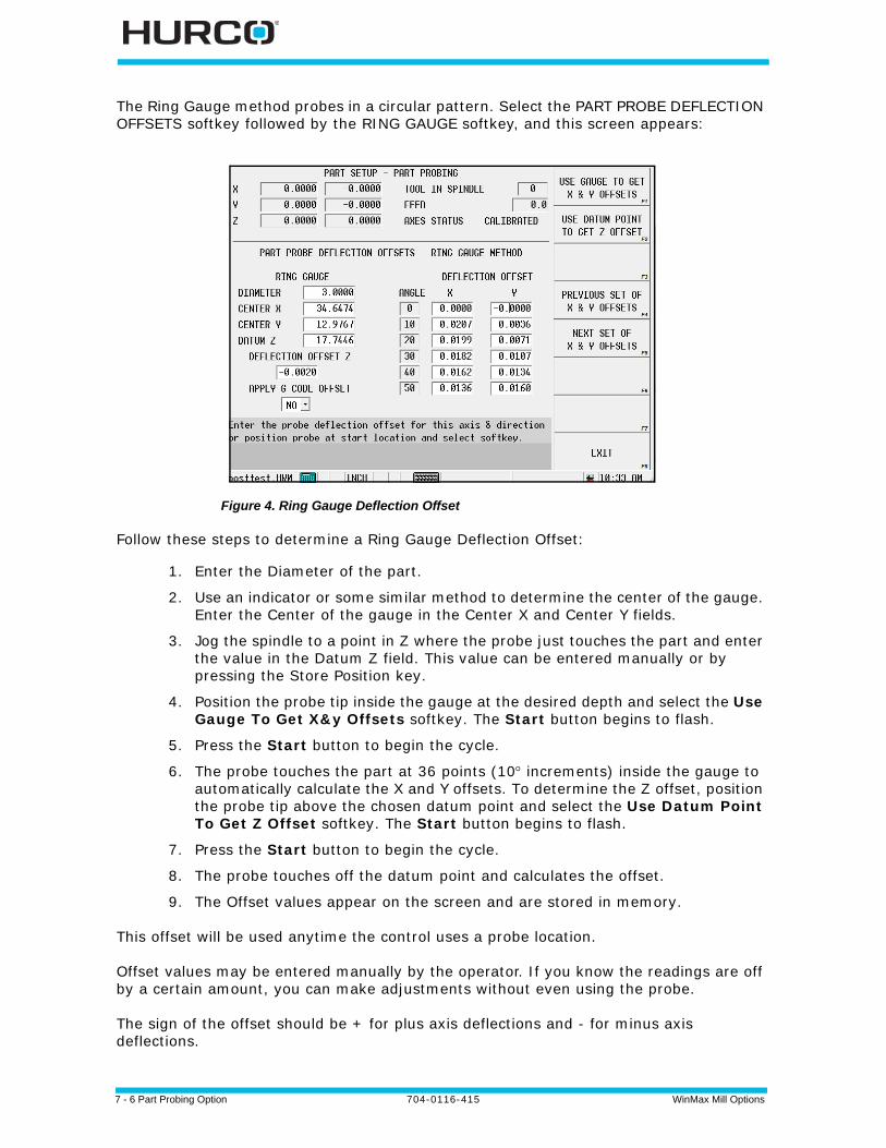
7 - 6 Part Probing Option 704-0116-415 WinMax Mill Options
The Ring Gauge method probes in a circular pattern. Select the PART PROBE DEFLECTION OFFSETS softkey followed by the RING GAUGE softkey, and this screen appears:
Figure 4. Ring Gauge Deflection Offset
Follow these steps to determine a Ring Gauge Deflection Offset:
1. Enter the Diameter of the part.
2. Use an indicator or some similar method to determine the center of the gauge. Enter the Center of the gauge in the Center X and Center Y fields.
3. Jog the spindle to a point in Z where the probe just touches the part and enter the value in the Datum Z field. This value can be entered manually or by pressing the Store Position key.
4. Position the probe tip inside the gauge at the desired depth and select the Use Gauge To Get X&y Offsets softkey. The Start button begins to flash.
5. Press the Start button to begin the cycle.
6. The probe touches the part at 36 points (10 increments) inside the gauge to automatically calculate the X and Y offsets. To determine the Z offset, position the probe tip above the chosen datum point and select the Use Datum Point To Get Z Offset softkey. The Start button begins to flash.
7. Press the Start button to begin the cycle.
8. The probe touches off the datum point and calculates the offset.
9. The Offset values appear on the screen and are stored in memory.
This offset will be used anytime the control uses a probe location.
Offset values may be entered manually by the operator. If you know the readings are off by a certain amount, you can make adjustments without even using the probe.
The sign of the offset should be + for plus axis deflections and - for minus axis deflections.
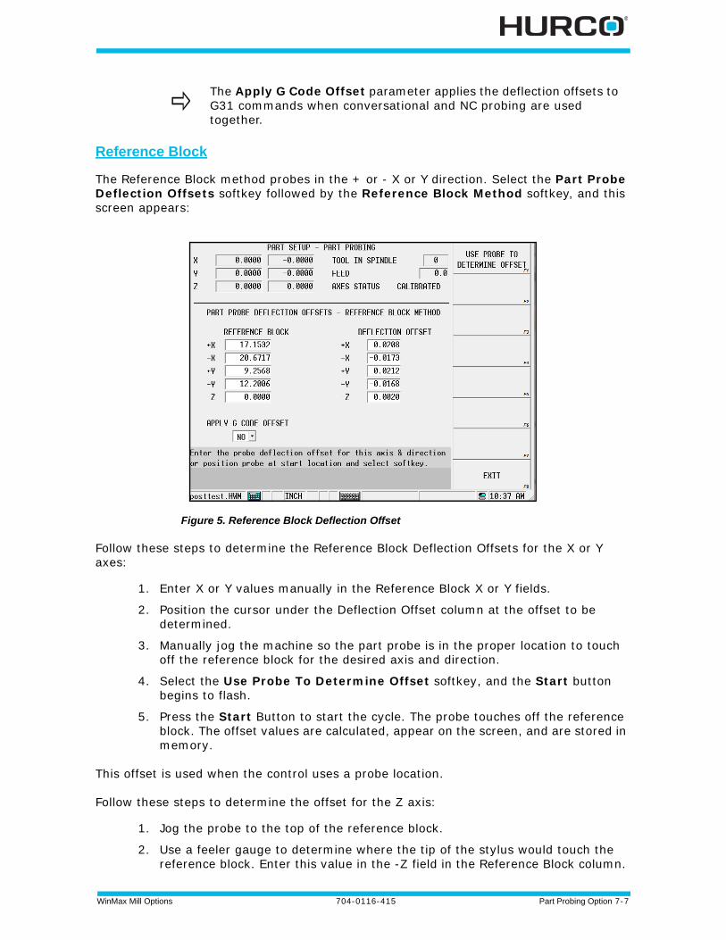
WinMax Mill Options 704-0116-415 Part Probing Option 7-7
Reference Block
The Reference Block method probes in the + or - X or Y direction. Select the Part Probe Deflection Offsets softkey followed by the Reference Block Method softkey, and this screen appears:
Figure 5. Reference Block Deflection Offset
Follow these steps to determine the Reference Block Deflection Offsets for the X or Y axes:
1. Enter X or Y values manually in the Reference Block X or Y fields.
2. Position the cursor under the Deflection Offset column at the offset to be determined.
3. Manually jog the machine so the part probe is in the proper location to touch off the reference block for the desired axis and direction.
4. Select the Use Probe To Determine Offset softkey, and the Start button begins to flash.
5. Press the Start Button to start the cycle. The probe touches off the reference block. The offset values are calculated, appear on the screen, and are stored in memory.
This offset is used when the control uses a probe location.
Follow these steps to determine the offset for the Z axis:
1. Jog the probe to the top of the reference block.
2. Use a feeler gauge to determine where the tip of the stylus would touch the reference block. Enter this value in the -Z field in the Reference Block column.
The Apply G Code Offset parameter applies the deflection offsets to G31 commands when conversational and NC probing are used together.
7 - 8 Part Probing Option 704-0116-415 WinMax Mill Options
3. Select the Use Probe To Determine Offset softkey. The probe touches off the part in the Z axis to determine the offset.
Offset values may be entered manually by the operator. If you know the readings are off by a certain amount, you can make adjustments without using the probe.
The sign of the offset should be + for plus axis deflections and - for minus axis deflections.
• The probe measures the part at 36 points in 10 increments on the ring gauge.
• The 4 points measured on the reference block correspond to the 0, 90, 180, and 270 values on the ring gauge. The remaining 32 values are estimated using the 4 actual measurements to fill in the 10 incremental offsets.
The Ring Gauge method is more accurate than the Reference Block method.
The Apply G Code Offset parameter applies the deflection offsets to G31 commands when conversational and NC probing are used together.
WinMax Mill Options 704-0116-415 Part Probing Option 7-9
Conversational Part Probing Cycles
Part probing is used for locating the position and alignment of the part on the table. Inserting a Probe Part Setup data block to run from the part program allows you to probe multiple parts and locate them at run time. This section describes probing cycles which are used for creating Probe Part Setup data blocks.
The software uses information programmed in the Part Setup screen to perform the Probing Cycles in Manual or Automatic mode.
There are two types of cycles available for probing different types of part features: Part Setup Probing Cycles and Part Skew Probing Cycles.
To select the Part Probe cycle type:
1. Select the Input console key to access the Input screen.
2. Press the Part Setup softkey.
3. Press the Part Probing softkey. The Part Setup screen is displayed with the Part Probing menu.
• Select the Part Zero Probe Cycles softkey for the Part Setup Probing Cycles. Refer to Part Setup Probing Cycles, on page 11 for details about programming these Manual Mode cycles. Refer to Automatic Mode, on page 42 for information about programming these Auto Mode cycles.
• Select the Part Skew Probe Cycles softkey to access the Part Skew Probing Cycles. Refer to Part Skew Probing Cycles, on page 34 for details about programming these Manual Mode cycles.Refer to Automatic Mode, on page 42 for information about programming these Auto Mode cycles.
Select the probing cycle type from the Part Setup screen with the Part Probing softkey.The cycles provide a method for allowing the software to automatically enter the Part Zero X, Part Zero Y, Probe Z, and X/Y Skew (deg) fields in the Part Setup screen.
Part Setup Screen
In addition to the standard Part Setup fields defined in the Getting Started with WinMax Mill manual, the software updates these Part Setup fields with data obtained during the probing cycles:
• Part Zero X; Y—store the part zero values established during the Part Setup Probing Cycles. Refer to Part Zero Storage, on page 33 for details about the Part Zero X and Y fields.
• Probe Z—represents the distance from Z zero to the top of the part (i.e., the height, or Z Plane), with the reference tool or part probe in the spindle.
• Z zero is the Z calibration point of the Z axis (Z = 0.0000).
• The software adjusts tool length values automatically and Tool Zero Calibration is recalculated anytime Probe Z is changed.
Refer to Determine Probe Z, on page 7 - 9 of Tool Probing for more details about these calculations.
• X/Y Skew (deg.)—represents, in degrees, how far the part is from perfect
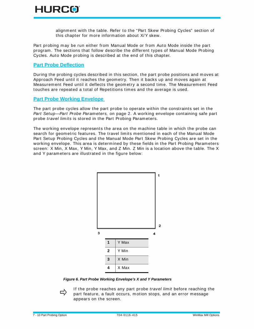
7 - 10 Part Probing Option 704-0116-415 WinMax Mill Options
alignment with the table. Refer to the “Part Skew Probing Cycles” section of this chapter for more information about X/Y skew.
Part probing may be run either from Manual Mode or from Auto Mode inside the part program. The sections that follow describe the different types of Manual Mode Probing Cycles. Auto Mode probing is described at the end of this chapter.
Part Probe Deflection
During the probing cycles described in this section, the part probe positions and moves at Approach Feed until it reaches the geometry. Then it backs up and moves again at Measurement Feed until it deflects the geometry a second time. The Measurement Feed touches are repeated a total of Repetitions times and the average is used.
Part Probe Working Envelope
The part probe cycles allow the part probe to operate within the constraints set in the Part Setup—Part Probe Parameters, on page 2. A working envelope containing safe part probe travel limits is stored in the Part Probing Parameters.
The working envelope represents the area on the machine table in which the probe can search for geometric features. The travel limits mentioned in each of the Manual Mode Part Setup Probing Cycles and the Manual Mode Part Skew Probing Cycles are set in the working envelope. This area is determined by these fields in the Part Probing Parameters screen: X Min, X Max, Y Min, Y Max, and Z Min. Z Min is a location above the table. The X and Y parameters are illustrated in the figure below:
Figure 6. Part Probe Working Envelope’s X and Y Parameters
1 Y Max
2 Y Min
3 X Min
4 X Max
If the probe reaches any part probe travel limit before reaching the part feature, a fault occurs, motion stops, and an error message appears on the screen.

WinMax Mill Options 704-0116-415 Part Probing Option 7-11
Each cycle’s feed rate is determined by the value set in the Part Probing Parameters Approach Feed and Measurement Feed fields.
Part Setup Probing Cycles
The table below describes the process for each Part Setup Probing Cycle:

7 - 12 Part Probing Option 704-0116-415 WinMax Mill Options
Table 1. Part Setup Probing Cycles
Cycle Type Cycle Parameter Input
Automatic Execution
Results Displayed
Optional Storage
Edge AxisProbe DirectionPositive or NegativePreset X or Y
Approach edge.Retract.Return to Start Position.
Deflection Position X, Y, or Z
Deflection Position X, Y, or Z is Part Zero X, Part Zero Y,orProbe Z.
HoleCirclePocket
Start Angle 1, 2, 3Preset XPreset Y
Approach 3 Circle Points from inside.Position Probe into Center.
Center XCenter YDiameter
Center is Part Zero X and Part Zero Y.
Cylinder Probing RadiusStart Angle 1, 2, 3Z DepthPreset XPreset Y
Approach 3 Cylinder points from outside.Position Probe above cylinder Center.
Center XCenter YDiameter
Center is Part Zero X and Part Zero Y.
Rectangular Pocket
Preset XPreset Y
Approach the 4 pocket walls from inside.Position Probe into pocket Center.
Center (X)Center (Y)Length (X)Length (Y)
Center is Part Zero X and Part Zero Y.
Rectangular Solid
Probing Length (X)Probing Length (Y)Z DepthPreset XPreset Y
Cycle StartApproach the 4 Rectangle walls from outside.Position Probe above rectangle Center.
Center (X)Center (Y)Length (X)Length (Y)
Center is Part Zero X and Part Zero Y.
Plane Intersection
X Probe DirectionOffset 1Offset 2Y Probe DirectionOffset 1Offset 2Preset XPreset Y
Cycle StartApproach 2 points on each of the two planes.Return to Start Position.
Intersection point of the two planes in the X/Y coordinate system
Intersection point is Part Zero X and Part Zero Y.
WinMax Mill Options 704-0116-415 Part Probing Option 7-13
Manual Mode Part Setup Probing Cycles
During a Part Setup Probing cycle, the probe moves to specified points on the part, deflects, and stops in the center or at the Start Position, depending on the part feature. From the Part Setup screen, use the PROBING (F5) softkey to access the Probing Cycles.
Each cycle is described in detail in the following sections. When the cycle is finished, the software displays values representing the desired features. The fields for each cycle vary and are defined with each cycle description.
You can accept these values by pressing the ACCEPT POSITION AS PART ZERO softkey when it appears. If you have entered Preset X or Preset Y offsets, these offsets are subtracted from the probed Part Zero values, and the new Part Zero values appear after pressing the ACCEPT POSITION AS PART ZERO softkey.
Follow these steps to access the Part Probe Cycles:
1. From the Part Setup screen, select the Part Probing softkey.
2. Select the Part Zero Probe Cycles softkey. The probe cycle softkeys appear. Select a softkey to select a cycle.
Depending on the Probing Cycle selected, different probing fields appear on the Part Setup screen.
The following sections describe how to program each of the Part Setup Probing Cycles.
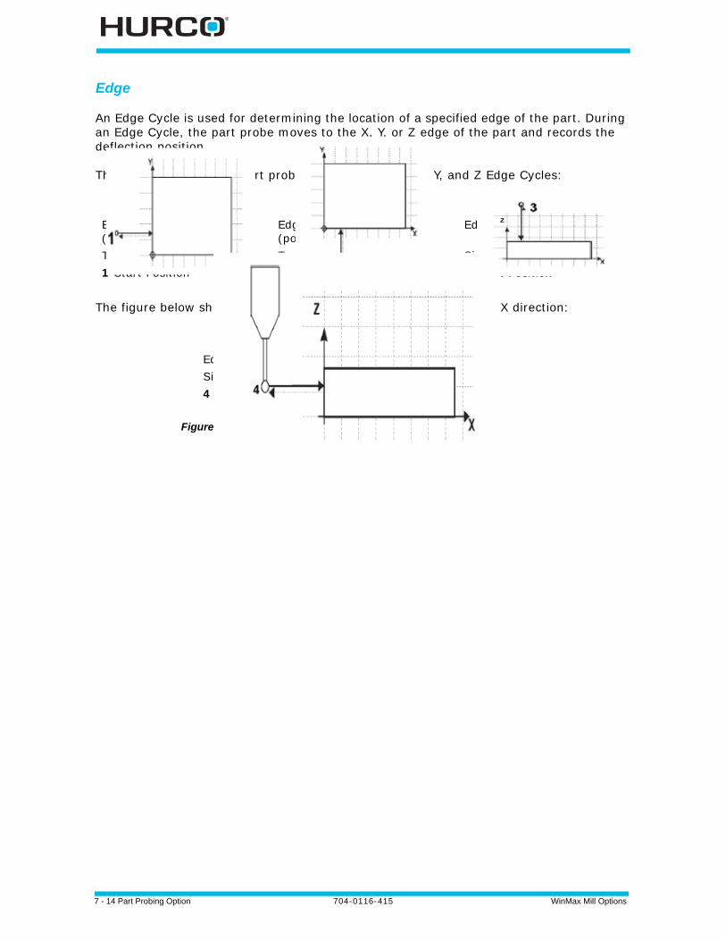
7 - 14 Part Probing Option 704-0116-415 WinMax Mill Options
Edge
An Edge Cycle is used for determining the location of a specified edge of the part. During an Edge Cycle, the part probe moves to the X, Y, or Z edge of the part and records the deflection position.
The figure below shows part probe movement during X, Y, and Z Edge Cycles:
The figure below shows a side view of an Edge cycle probing in the X direction:
Figure 7. Part Probe Movement for Edge Probing Cycles
Edge Probing in X direction (positive) Top View1 Start Position
Edge Probing in Y direction (positive)Top View2 Start Position
Edge Probing in Z direction
Side View3 Start Position
Edge Probing in X direction (positive)Side View4 Start Position
WinMax Mill Options 704-0116-415 Part Probing Option 7-15
In addition to the standard Part Setup fields which are defined in the Getting Started with WinMax Mill manual, these Part Setup fields appear for the Edge Probing Cycle:
• Part Zero X, Y; Probe Z—contains the machine coordinate position of the Edge Cycle. These fields appears upon completion of the Edge Cycle.
• Part Zero Cycle—contains the type of cycle chosen from the Part Zero Probe Cycles softkey menu.
• Probing Axis—identifies the axis to move toward the edge of the part: X Axis, Y Axis, or Z Axis.
• Probing Direction—contains the direction to probe: Positive or Negative. This field appears when the Probing Axis is X or Y. It is not available for Probing Axis Z.
• Preset X or Preset Y—define an offset for Part Zero X and/or Part Zero Y. Entering offsets in either of these fields is optional.
The offset(s) will be subtracted from the center point of the circle and applied to Part Zero X and Y if you select the ACCEPT POSITION AS PART ZERO softkey, which appears after the cycle has been run. This field appears when the Probing Axis is X or Y. It is not available for Probing Axis Z.
Follow these steps to program an Edge Probing Cycle:
1. From the Part Zero Probe Cycles softkey menu, select Edge.
2. In the Probing Axis field, select the axis to move toward the edge of the part: X Axis, Y Axis, or Z Axis.
3. In the Probing Direction field, select the direction to probe: Positive or Negative. This field appears when the Probing Axis is X or Y. It is not available for Z Probing Axis.
4. If you want to program an offset from Part Zero X or Part Zero Y, enter the offset value in the Preset X or Preset Y field. This field appears when the Probing Axis is X or Y. It is not available for Z Probing Axis.
When the Part Setup fields have been entered, start the Edge Probing Cycle:
1. Place the part probe in the spindle and jog the probe to the Start Position, near the edge to be probed.
2. Press the Start Probing Cycle softkey. The Start Cycle button flashes.
3. Press the flashing Start Cycle button.
a. The probing axis moves in the specified direction until the probe is deflected.
• f no deflection occurs before the probe reaches the probe’s travel limit, the cycle is stopped and an error message appears.
• To clear the error message and return to the Part Setup screen, press any key.
• Check the Part Probe Parameters and the part fixturing. Make adjustments as necessary and re-start the cycle.
7 - 16 Part Probing Option 704-0116-415 WinMax Mill Options
b. The deflection position appears in the Edge (X,Y, or Z) field when the cycle is finished.
c. The probing axis returns to the Start Position.
4. The Accept Position As Part Zero and Do Not Accept softkeys appear. Press the appropriate softkey.
• The Accept Position As Part Zero softkey accepts the edge position and subtracts the Preset X or Y value to determine Part Zero.
• The Do Not Accept softkey ignores the edge position value and the Preset X or Y value. Part Zero remains unchanged.
Refer to Part Zero Storage, on page 33 for more information.
5. The initial Part Setup screen appears with Part Zero entries established during the cycle.

WinMax Mill Options 704-0116-415 Part Probing Option 7-17
Hole or Circle Pocket
The Hole or Circle Pocket Cycle is used for determining the center location and the diameter of a hole or pocket. During a Hole or Circle Pocket Cycle, the part probe moves from the inside of the circle out to three points on the edge, touches at each point, and returns to the Start Position within the circle after each touch. The software records each deflection position and calculates the center location. The probe positions in the center of the pocket.
The figure below shows part probe movement during a Hole or Circle Pocket Cycle:
Figure 8. Hole or Circle Pocket Probing Cycle
1 Start Position
2 Start Angle 1
3 Start Angle 2
4 Start Angle 3
5 Start Position
6 Start Angle 1
7 - 18 Part Probing Option 704-0116-415 WinMax Mill Options
In addition to the standard Part Setup fields which are defined in the Getting Started with WinMax Mill manual, these Part Setup fields appear for the Hole or Circle Pocket Probing Cycle:
• Center X—identifies the Center X machine coordinate location. This field appears upon completion of the cycle.
• Center Y—identifies the Center Y machine coordinate location. This field appears upon completion of the cycle.
• Diameter—identifies the diameter of the hole or circle pocket. This field appears upon completion of the cycle.
• Part Probe Cycle—contains the type of cycle chosen from the Part Zero Probe Cycles menu.
• Start Angle 1; Start Angle 2; Start Angle 3—define the three probe deflection points. Relative to the 3:00 position, and increasing counter-clockwise as viewed from above the part, the default angles are 0, 120, and 240, respectively. Change the angles if the part contains geometry that interferes with the defaults.
• Preset X and Preset Y—define an offset for Part Zero X and/or Part Zero Y. Entering offsets in either of these fields is optional.
The offset(s) will be subtracted from the center point of the circle and applied to Part Zero X and Y if you select the ACCEPT POSITION AS PART ZERO (F1) softkey, which appears after the cycle has been run.
Follow these steps to program a Hole or Circle Pocket Probing Cycle:
1. From the Part Zero Probe Cycles softkey menu, select Hole or Circle Pocket.
2. In the Start Angle fields, enter the desired approach angles.
3. If you want to program an offset from Part Zero X or Part Zero Y, enter the offset value in the Preset X or Preset Y field.
When the Part Setup fields have been entered, start the Hole or Circle Pocket Probing Cycle:
1. Place the part probe in the spindle and jog the probe to the Start Position, into the pocket and below the surface.
2. Press the START PROBING CYCLE (F1) softkey. The Start Cycle button flashes.
3. Press the Start Cycle button.
a. The probe moves along Start Angle 1 until it is deflected at the edge of the hole or circle pocket.
• If no deflection occurs before the probe reaches its travel limit, the cycle is stopped and an error message appears.
• To clear the error message and return to the Part Setup screen, press any key.
• Check the Part Probe Parameters and the part fixturing. Make adjustments as necessary and re-start the cycle.
WinMax Mill Options 704-0116-415 Part Probing Option 7-19
b. After the first deflection, the probe returns to the Start Position. c. The probe moves along Start Angle 2 to a second contact point. d. After the deflection, the probe returns to the Start Position. e. The probe moves along Start Angle 3 to a third contact point.f. After the deflection, the probe returns to the Start Position. g. Using the three contact points, the control calculates the diameter and the
center (X and Y) of the hole.
h. The probe moves to the center of the hole or circle pocket. The results appear in the Center X, Center Y, and Diameter fields.
4. The ACCEPT POSITION AS PART ZERO (F1) and DO NOT ACCEPT (F2) softkeys appear. Press the appropriate softkey.
• The ACCEPT POSITION AS PART ZERO (F1) softkey accepts the center position and subtracts the presets to determine Part Zero.
• The DO NOT ACCEPT (F2) softkey ignores the center value and the Preset X or Y value. Part Zero remains unchanged.
Refer to Part Zero Storage, on page 33 for more information.
5. The initial Part Setup screen appears with Part Zero entries established during the cycle.
7 - 20 Part Probing Option 704-0116-415 WinMax Mill Options
Cylinder
The Cylinder Cycle is used for determining the center location and the diameter of a cylinder. During a Cylinder Cycle, the part probe moves from the Start Position above the cylinder, out and down to three points around the diameter. The probe touches at each point and returns up and over to the Start Position above the cylinder after each touch. The software determines the diameter and the center location.
The figure below shows part probe movement during a Cylinder Cycle:
Figure 9. Cylinder Probing Cycle
1 Start Position
2 Start Angle 1
3 Start Angle 2
4 Start Angle 3
5 Start Position
6 Start Angle 1
WinMax Mill Options 704-0116-415 Part Probing Option 7-21
In addition to the standard Part Setup fields which are defined in the Getting Started with WinMax Mill manual, these Part Setup fields appear for the Cylinder Cycle:
• Center X—identifies the Center X machine coordinate location.This field appears upon completion of the cycle.
• Center Y—identifies the Center Y machine coordinate location.This field appears upon completion of the cycle.
• Diameter—identifies the diameter of the cylinder. This field appears upon completion of the cycle.
• Part Probe Cycle—contains the type of cycle chosen from the Part Zero Probe Cycles softkey menu.
• Probing Radius—defines a value for the probe search radius. This value is used for determining the point at which the probe stops horizontal travel and begins to move downward.
• Start Angle 1; Start Angle 2; Start Angle 3—define the three probe deflection points. Relative to the 3:00 position and increasing counterclockwise as viewed from above the part, the default angles are 0, 120, and 240, respectively. Change the angles if the part contains geometry that interferes with the defaults.
• Z Depth—defines the distance, relative to the Start Position, the Z axis moves downward before changing direction and searching horizontally for each contact point on the cylinder’s diameter.
• Preset X and Preset Y—define an offset for Part Zero X and/or Part Zero Y. Entering offsets in either of these fields is optional.
The offset(s) will be subtracted from the center point of the circle and applied to Part Zero X and Y if you select the ACCEPT POSITION AS PART ZERO (F1) softkey, which appears after the cycle has been run.
Follow these steps to program a Cylinder Probing Cycle:
1. From the Part Zero Probe Cycles softkey menu, select Cylinder.
2. In the Probing Radius field, enter the probe search radius.
3. In the Start Angle fields, enter the desired approach angles.
4. In the Z Depth field, enter the distance the Z axis moves down before changing direction and searching horizontally for each contact point.
5. If you want to program an offset from Part Zero X and Part Zero Y, enter the offset value in the Preset X and Preset Y field.
There should be no deflection during the Z move.
7 - 22 Part Probing Option 704-0116-415 WinMax Mill Options
When the Part Setup fields have been entered, start the Cylinder Probing Cycle:
1. Place the part probe in the spindle and jog the probe to the Start Position, above the cylinder.
2. Press the START PROBING CYCLE (F1) softkey. The Start Cycle button flashes.
3. Press the flashing Start Cycle button.
a. The probe moves along Start Angle 1 until it reaches the Probing Radius.
• If no deflection occurs before the probe reaches the probe’s travel limit, the cycle is stopped and an error message appears.
• To clear the error message and return to the Part Setup screen, press any key.
• Check the Part Probe Parameters and the part fixturing. Make adjustments as necessary and re-start the cycle.
b. The probe moves down until it reaches Z Depth.
• If deflection occurs during the Z move, axis motion stops and an error message appears.
• To clear the error message and return to the Part Setup screen, press any key.
• Check the Part Probe Parameters and the part fixturing. Make adjustments as necessary and re-start the cycle.
c. The probe moves backwards in the X/Y plane toward the Start Position in order to find a contact point.
d. After deflection, the probe moves up and over to the Start Position above the cylinder.
e. The probe moves along Start Angle 2 until it reaches the Probing Radius. The same motion occurs as with Start Angle 1.
f. After the deflection, the probe moves up and over to the Start Position above the cylinder.
g. The probe moves along Start Angle 3 until it reaches the Probing Radius. The same motion occurs as with Start Angles 1 and 2.
h. After the third deflection, the control uses the three contact points and calculates the diameter and center (X and Y) of the cylinder.
i. The probe moves up and over to the center above the Z Plane of the cylinder. The results appear in the Center X, Center Y, and Diameter fields.
4. The ACCEPT POSITION AS PART ZERO (F1) and DO NOT ACCEPT (F2) softkeys appear. Press the appropriate softkey.
• The ACCEPT POSITION AS PART ZERO (F1) softkey accepts the center and subtracts the presets to determine part zero.
• The DO NOT ACCEPT (F2) softkey ignores the center values and the Preset X or Y value. Part Zero remains unchanged.
Refer to Part Zero Storage, on page 33 for more information.
5. The initial Part Setup screen appears with Part Zero entries established during

WinMax Mill Options 704-0116-415 Part Probing Option 7-23
the cycle.
Rectangular Pocket Inside
The Rectangular Pocket Inside (or Rectangular Pocket) Cycle is used for determining the center location of the pocket and the X and Y length of the rectangle. During a Rectangular Pocket Cycle, the part probe moves from inside the pocket out to a point on each edge of the rectangle, touches at each point, and returns to the Start Position after each touch. The software records each deflection position and calculates the center location and lengths.
The figure below shows part probe movement during a Rectangular Pocket Cycle.
Figure 10. Rectangular Pocket Probing Cycle
1 Start Position
2 Point 1
3 Point 2
4 Point 3
5 Point 4
6 Start Position
7 Point 1

7 - 24 Part Probing Option 704-0116-415 WinMax Mill Options
In addition to the standard Part Setup fields which are defined in the Programming Basics chapter of the Getting Started with WinMax manual, these Part Setup fields appear for the Rectangular Pocket Cycle:
• Center X—identifies the Center X machine coordinate location.This field appears upon completion of the cycle.
• Center Y—identifies the Center Y machine coordinate location.This field appears upon completion of the cycle.
• Length (X)—identifies the X length of the pocket. This field appears upon completion of the cycle.
• Length (Y)—identifies the Y length of the pocket. This field appears upon completion of the cycle.
• Part Probe Cycle—contains the type of cycle chosen from the Part Zero Probe Cycles softkey menu.
• Preset X or Preset Y—define an offset for Part Zero X and/or Part Zero Y. Entering offsets in either of these fields is optional.
The offset(s) will be subtracted from the center point of the pocket and applied to Part Zero X and Y if you select the ACCEPT POSITION AS PART ZERO (F1) softkey, which appears after the cycle has been run.
Follow these steps to program a Rectangular Pocket Cycle:
1. From the Part Zero Probe Cycles softkey menu, select Rectangular Pocket Inside.
2. If you want to program an offset for Part Zero X or Part Zero Y, enter the offset value in the Preset X or Preset Y field.
When the Part Setup fields have been entered, start the Rectangular Pocket Cycle:
1. Place the part probe in the spindle and jog the probe to the Start Position, into the pocket and below the surface.
2. Press the START PROBING CYCLE (F1) softkey. The Start Cycle button flashes.
3. Press the Start Cycle button.
a. The probe moves in the positive X direction until it is deflected at the edge of the pocket.
• f no deflection occurs before the probe reaches its horizontal travel limit, the cycle is stopped and an error message appears.
• To clear the error message and return to the Part Setup screen, press any key.
• Check the Part Probe Parameters and the part fixturing. Make adjustments as necessary and re-start the cycle.
b. After the first deflection, the probe returns to the Start Position.c. The probe moves in the negative X direction, reaches a second contact
point, and returns to the Start Position.
WinMax Mill Options 704-0116-415 Part Probing Option 7-25
d. The probe moves in the positive Y direction, reaches a third contact point, and returns to the Start Position.
e. The probe moves in the negative Y direction, reaches a fourth contact point, and returns to the Start Position.
f. Using the four contact points, the control calculates the length of the pocket in the X and Y directions and the center (X and Y) of the pocket.
g. The probe moves to the center of the rectangle. The results are displayed on the screen in the Center X, Center Y, Length (X), and Length (Y) fields.
4. The ACCEPT POSITOIN AS PART ZERO (F1) and DO NOT ACCEPT (F2) softkeys appear. Press the appropriate softkey.
• The ACCEPT POSITOIN AS PART ZERO (F1) softkey accepts the center and subtracts the presets to determine part zero.
• The DO NOT ACCEPT (F2) softkey ignores the center and length values and the Preset X or Y value. Part Zero remains unchanged.
Refer to Part Zero Storage, on page 33 for more information.
5. The initial Part Setup screen appears with Part Zero entries established during the cycle.
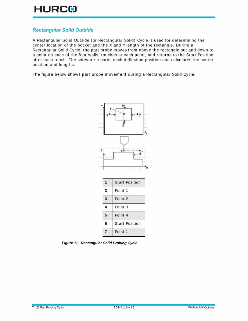
7 - 26 Part Probing Option 704-0116-415 WinMax Mill Options
Rectangular Solid Outside
A Rectangular Solid Outside (or Rectangular Solid) Cycle is used for determining the center location of the pocket and the X and Y length of the rectangle. During a Rectangular Solid Cycle, the part probe moves from above the rectangle out and down to a point on each of the four walls, touches at each point, and returns to the Start Position after each touch. The software records each deflection position and calculates the center position and lengths.
The figure below shows part probe movement during a Rectangular Solid Cycle:
Figure 11. Rectangular Solid Probing Cycle
1 Start Position
2 Point 1
3 Point 2
4 Point 3
5 Point 4
6 Start Position
7 Point 1
WinMax Mill Options 704-0116-415 Part Probing Option 7-27
In addition to the standard Part Setup fields which are defined in the Programming Basics chapter of the Getting Started with WinMax manual, these Part Setup fields appear for the Rectangular Solid Cycle:
• Center X—identifies the Center X machine coordinate location. This field appears upon completion of the cycle.
• Center Y—identifies the Center Y machine coordinate location. This field appears upon completion of the cycle.
• Length (X)—identifies the X length of the rectangle. This field appears upon completion of the cycle.
• Length (Y)—identifies the Y length of the rectangle. This field appears upon completion of the cycle.
• Part Probe Cycle—contains the type of cycle chosen from the Part Zero Probe Cycles softkey menu.
• Probing Length X—identifies a maximum value of the estimated X length. Half of this value is used to determine the point at which the Z axis begins to move downward; i.e., its horizontal travel limit for X.
• Probing Length Y—identifies a maximum value of the estimated Y length. Half of this value is used to determine the point at which the Z axis begins to move downward; i.e., its horizontal travel limit for Y.
• Z Depth—defines the distance, relative to the Start Position, the Z axis moves downward before changing direction and searching horizontally for each contact point on the cylinder’s diameter.
• Preset X and Preset Y—define an offset for Part Zero X and/or Part Zero Y. Entering offsets in either of these fields is optional.
The offset(s) will be subtracted from the center point of the rectangle and applied to Part Zero X and Y if you select the ACCEPT POSITION AS PART ZERO (F1) softkey, which appears after the cycle has been run.
Follow these steps to program a Rectangular Solid Cycle:
1. From the Part Setup Probe Cycles softkey menu, select Rectangular Solid Outside.
2. In the Probing Length X field, enter an estimate for the X length.
3. In the Probing Length Y field, enter an estimate for the Y length.
4. In the Z Depth field, enter the distance the Z axis should move down.
5. If you want to program an offset for Part Zero X and Part Zero Y, enter the offset value in the Preset X and Preset Y field.
There should be no deflection during the Z move.
7 - 28 Part Probing Option 704-0116-415 WinMax Mill Options
When the Part Setup fields have been entered, start the Rectangular Solid Cycle:
1. Place the part probe in the spindle and jog the probe to the Start Position, above the middle of the rectangle.
2. Press the START PROBING CYCLE (F1) softkey. The Start Cycle button flashes.
3. Press the Start Cycle button.
a. The probe moves in the positive X direction, until it reaches its horizontal travel limit determined by the Probing Length X field.
• If no deflection occurs before the probe reaches the probe’s travel limit, the cycle is stopped and an error message appears.
• To clear the error message and return to the Part Setup screen, press any key.
• Check the Part Probe Parameters and the part fixturing. Make adjustments as necessary and re-start the cycle.
b. The probe moves down until it reaches Z Depth.
• If deflection occurs during the Z move, axis motion stops and an error message appears.
• To clear the error message and return to the Part Setup screen, press any key.
• Check the Part Probe Parameters and the part fixturing. Make adjustments as necessary and re-start the cycle.
c. The probe moves backwards in the X/Y plane toward the Start Position and deflects.
d. The probe returns up and over to the Start Position. e. The probe moves in the negative X direction until it reaches its horizontal
travel limit determined by the Probing Length X field.f. The probe moves down until it reaches Z Depth.g. The probe moves backwards in the X/Y plane toward the Start Position and
deflects.h. The probe moves up and over to the Start Position. i. The probe moves in the positive Y direction until it reaches its horizontal
travel limit determined by the Probing Length Y field.j. The probe moves down until it reaches Z Depth.k. The probe moves backwards in the X/Y plane toward the Start Position and
deflects.l. The probe moves up and over to the Start Position. m. The probe moves in the negative Y direction until it reaches its horizontal
travel limit determined by the Probing Length Y field.n. The probe moves down until it reaches Z Depth.o. The probe moves backwards in the X/Y plane toward the Start Position and
deflects.p. The probe moves up and over to the Start Position. q. After the last deflection, the control calculates the X and Y lengths of the
solid and the center (X and Y) of the rectangle.

WinMax Mill Options 704-0116-415 Part Probing Option 7-29
r. The results appear in the Center X, Center Y, Length (X), and Length (Y), fields. The probe moves to the center above the rectangle.
4. The ACCEPT POSITION AS PART ZERO (F1) and DO NOT ACCEPT (F2) softkeys appear. Press the appropriate softkey.
• The ACCEPT POSITION AS PART ZERO (F1) softkey accepts the center and subtracts the presets to determine part zero.
• The DO NOT ACCEPT (F2) softkey ignores the center and length values and the Preset X or Y value. Part Zero remains unchanged.
Refer to Part Zero Storage, on page 33 for more information.
5. The initial Part Setup screen appears with Part Zero entries established during the cycle.
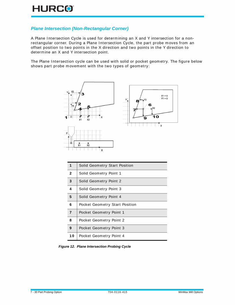
7 - 30 Part Probing Option 704-0116-415 WinMax Mill Options
Plane Intersection (Non-Rectangular Corner)
A Plane Intersection Cycle is used for determining an X and Y intersection for a non-rectangular corner. During a Plane Intersection Cycle, the part probe moves from an offset position to two points in the X direction and two points in the Y direction to determine an X and Y intersection point.
The Plane Intersection cycle can be used with solid or pocket geometry. The figure below shows part probe movement with the two types of geometry:
Figure 12. Plane Intersection Probing Cycle
1 Solid Geometry Start Position
2 Solid Geometry Point 1
3 Solid Geometry Point 2
4 Solid Geometry Point 3
5 Solid Geometry Point 4
6 Pocket Geometry Start Position
7 Pocket Geometry Point 1
8 Pocket Geometry Point 2
9 Pocket Geometry Point 3
10 Pocket Geometry Point 4
WinMax Mill Options 704-0116-415 Part Probing Option 7-31
In addition to the standard Part Setup fields which are defined in the Programming Basics chapter of the Getting Started with WinMax manual, these Part Setup fields appear for the Plane Intersection Cycle:
• Corner X—defines the X position of the intersection. This field appears when the cycle is finished.
• Corner Y—defines the Y position of the intersection. This field appears when the cycle is finished.
• Probing Direction X—select the X direction to probe: Positive or Negative.
• Offset 1—defines the first Y offset position.
• Offset 2—defines the second Y offset position.
• Probing Direction Y—select the Y direction to probe: Positive or Negative.
• Offset 1—defines the first X offset position.
• Offset 2—defines the second X offset position.
• Preset X and Preset Y—define an offset for Part Zero X and/or Part Zero Y. Entering offsets in either of these fields is optional.
The offset(s) will be subtracted from the corner point and applied to Part Zero X and Y if you select the ACCEPT POSITION AS PART ZERO (F1) softkey, which appears after the cycle has been run.
Follow these steps to program a Plane Intersection Cycle:
1. From the Part Zero Probe Cycles softkey menu, select Plane Intersection.
2. In the Probing Direction X field, select Positive or Negative.
3. In the Offset 1 field, enter the position for the first Y Offset, relative to the Start Position.
4. In the Offset 2 field, enter the position for the second Y Offset, relative to the Start Position.
5. In the Probing Direction Y field, select Positive or Negative.
6. In the Offset 1 field, enter the position for the first X Offset, relative to the Start Position.
7. In the Offset 2 field, enter the position for the second X Offset, relative to the Start Position.
8. If you want to program an offset from Part Zero X or Part Zero Y, enter the offset value in the Preset X or Preset Y field.
When the Part Setup fields have been entered, start the Plane Intersection Cycle:
1. Place the part probe in the spindle and jog the probe into the Start Position, near the non-rectangular corner.
2. Press the START PROBING CYCLE (F1) softkey. The Start Cycle button flashes.
7 - 32 Part Probing Option 704-0116-415 WinMax Mill Options
3. Press the flashing Start Cycle button.
a. The probe moves the direction specified in Probing Direction X the distance specified in Offset 1.
• If no deflection occurs before the probe reaches the probe’s travel limit, the cycle is stopped and an error message appears.
• To clear the error message and return to the Part Setup screen, press any key.
• Check the Part Probe Parameters and the part fixturing. Make adjustments as necessary and re-start the cycle.
b. The probe reaches the first contact point with the first edge in the X direction, deflects, and moves to the position specified in Offset 2.
c. The probe reaches the second contact point in the X direction and deflects. d. The probe returns to the starting point.e. The probe moves the direction specified in Probing Direction Y the distance
specified in Offset 1.f. The probe reaches the first contact point with the first edge in the Y
direction, deflects, and moves to the position specified in Offset 2. g. The probe reaches the second contact point in the Y direction and deflects.h. The probe returns to the Start Position.
i. Using the four contact points, the control calculates the X and Y intersection points. The results appear in the Corner X and Corner Y fields.
4. The ACCEPT POSITION AS PART ZERO (F1) and DO NOT ACCEPT (F2) softkeys appear. Press the appropriate softkey.
• The ACCEPT POSITION AS PART ZERO (F1) softkey accepts the corner position and subtracts the Preset X or Y value to determine Part Zero.
• The DO NOT ACCEPT (F2) softkey ignores the corner values and the Preset X or Y value. Part Zero remains unchanged.
Refer to Part Zero Storage, on page 33 for more information.
5. The initial Part Setup screen appears with Part Zero entries established during the cycle.
WinMax Mill Options 704-0116-415 Part Probing Option 7-33
Part Zero Storage
At the end of each Probing Cycle, the results of the cycle are displayed on the screen. These results are displayed in machine coordinates and do not include the Preset values.
Selecting the ACCEPT POSITION AS PART ZERO (F1) softkey accepts the probed values and subtracts the presets to determine part zero. The new Part Zero values appear in the Part Zero X and Part Zero Y fields.
With an Edge probing cycle the probe moves only one axis. Therefore, only one of Part Zero X, Part Zero Y, or Probe Z is set. With all other cycles, both Part Zero X and Part Zero Y are determined at the same time.
Cycle Results
Edge Contact Position (X, Y, or Z)
Hole or Circle Pocket Diameter, Center (X and Y)
Cylinder Diameter, Center (X and Y)
Rectangular Pocket Lengths (X and Y), Center (X and Y)
Rectangular Solid Lengths (X and Y), Center (X and Y)
Plane Intersect Corner (X and Y)
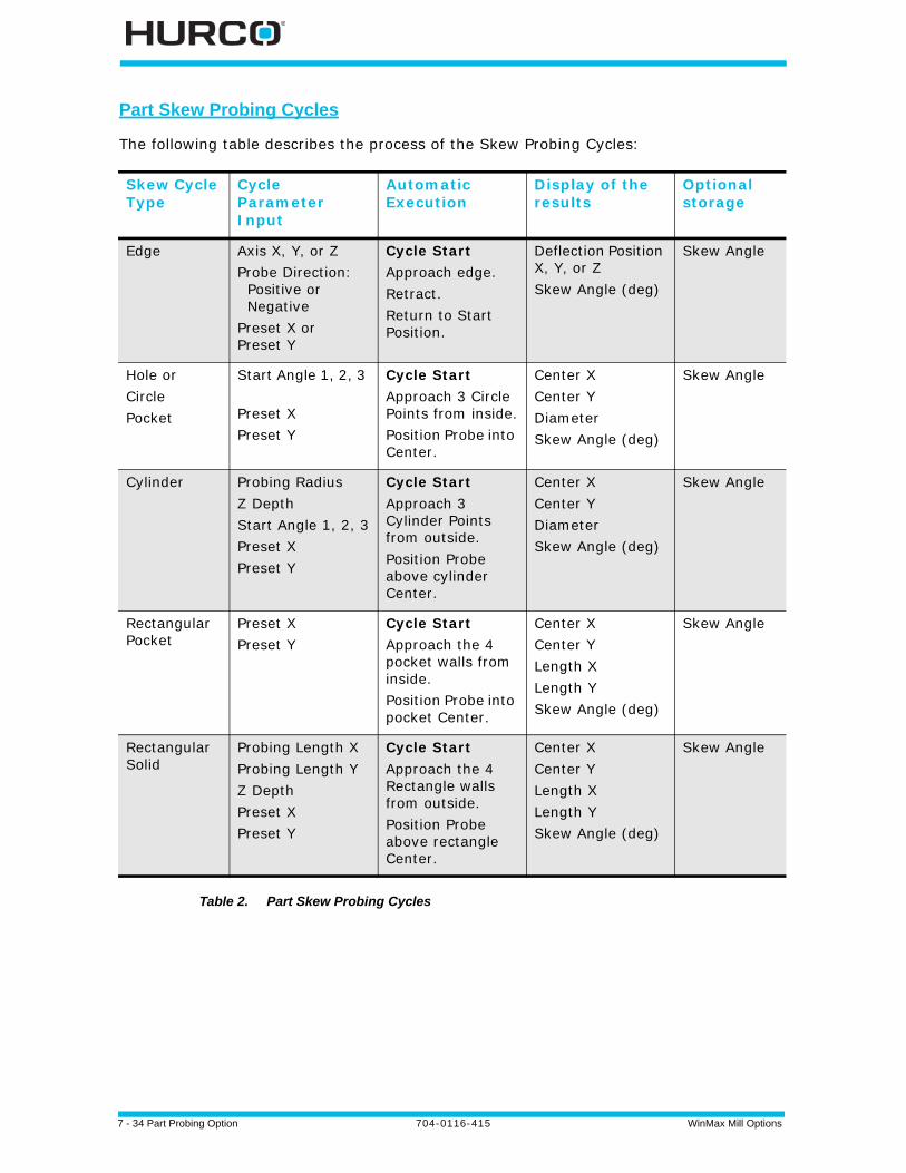
7 - 34 Part Probing Option 704-0116-415 WinMax Mill Options
Part Skew Probing Cycles
The following table describes the process of the Skew Probing Cycles:
Table 2. Part Skew Probing Cycles
Skew Cycle Type
Cycle Parameter Input
Automatic Execution
Display of the results
Optional storage
Edge Axis X, Y, or ZProbe Direction: Positive or Negative Preset X orPreset Y
Cycle Start Approach edge.Retract.Return to Start Position.
Deflection Position X, Y, or ZSkew Angle (deg)
Skew Angle
Hole orCircle Pocket
Start Angle 1, 2, 3
Preset XPreset Y
Cycle Start Approach 3 Circle Points from inside.Position Probe into Center.
Center XCenter YDiameterSkew Angle (deg)
Skew Angle
Cylinder Probing RadiusZ Depth Start Angle 1, 2, 3Preset XPreset Y
Cycle Start Approach 3 Cylinder Points from outside.Position Probe above cylinder Center.
Center XCenter YDiameterSkew Angle (deg)
Skew Angle
Rectangular Pocket
Preset XPreset Y
Cycle Start Approach the 4 pocket walls from inside.Position Probe into pocket Center.
Center XCenter YLength XLength YSkew Angle (deg)
Skew Angle
Rectangular Solid
Probing Length XProbing Length YZ Depth Preset XPreset Y
Cycle Start Approach the 4 Rectangle walls from outside.Position Probe above rectangle Center.
Center XCenter YLength XLength YSkew Angle (deg)
Skew Angle

WinMax Mill Options 704-0116-415 Part Probing Option 7-35
Manual Mode Part Skew Probing Cycles
From the Part Setup screen, use the PROBING (F5) softkey to access the Probing Cycles. During a Part Skew Probing cycle the probe moves to specified points on the part, deflects, and stops in the center of the part feature. These cycles detect and compensate for X/Y skew in the workpiece. X/Y skew represents, in degrees, how far the part is from perfect alignment with the table.
• A positive skew angle means the part is rotated in a counterclockwise direction from the machine axes (as viewed from above the part).
• A negative skew angle indicates a clockwise rotation from the machine axes.
Although this angle, if known, may be manually typed in using the keypad, it is easier and more accurate to let the probe find the skew angle and automatically enter it.
After probing the Part Zero position as a reference, the skew cycles allow you to probe a second feature on the part and adjust all machining operations by the skew angle to exactly match the part.
When the cycle is finished, the software displays values representing the desired features. The fields for each cycle vary and are defined with each cycle description.
You can accept these values by pressing the Accept X/Y Skew Angle softkey when it appears. Preset X or Preset Y offsets are used in the skew calculation. The presets are subtracted from the probed Part Zero values, and the new Part Zero values appear after pressing the ACCEPT POSITION AS PART ZERO (F1) softkey.
For best results, it is recommended that you use the probe for determining Part Zero X, Part Zero Y, and X/Y Skew. Entering values for any of these fields with the keypad reduces the amount of information available for skew calculations. Also, the software must make assumptions that may reduce accuracy.
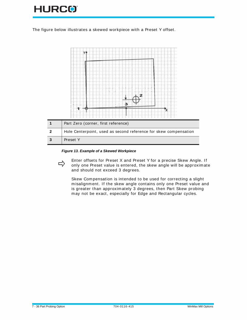
7 - 36 Part Probing Option 704-0116-415 WinMax Mill Options
The figure below illustrates a skewed workpiece with a Preset Y offset.
Figure 13. Example of a Skewed Workpiece
1 Part Zero (corner, first reference)
2 Hole Centerpoint, used as second reference for skew compensation
3 Preset Y
Enter offsets for Preset X and Preset Y for a precise Skew Angle. If only one Preset value is entered, the skew angle will be approximate and should not exceed 3 degrees.
Skew Compensation is intended to be used for correcting a slight misalignment. If the skew angle contains only one Preset value and is greater than approximately 3 degrees, then Part Skew probing may not be exact, especially for Edge and Rectangular cycles.
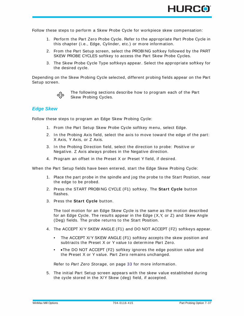
WinMax Mill Options 704-0116-415 Part Probing Option 7-37
Follow these steps to perform a Skew Probe Cycle for workpiece skew compensation:
1. Perform the Part Zero Probe Cycle. Refer to the appropriate Part Probe Cycle in this chapter (i.e., Edge, Cylinder, etc.) or more information.
2. From the Part Setup screen, select the PROBING softkey followed by the PART SKEW PROBE CYCLES softkey to access the Part Skew Probe Cycles.
3. The Skew Probe Cycle Type softkeys appear. Select the appropriate softkey for the desired cycle.
Depending on the Skew Probing Cycle selected, different probing fields appear on the Part Setup screen.
Edge Skew
Follow these steps to program an Edge Skew Probing Cycle:
1. From the Part Setup Skew Probe Cycle softkey menu, select Edge.
2. In the Probing Axis field, select the axis to move toward the edge of the part: X Axis, Y Axis, or Z Axis.
3. In the Probing Direction field, select the direction to probe: Positive or Negative. Z Axis always probes in the Negative direction.
4. Program an offset in the Preset X or Preset Y field, if desired.
When the Part Setup fields have been entered, start the Edge Skew Probing Cycle:
1. Place the part probe in the spindle and jog the probe to the Start Position, near the edge to be probed.
2. Press the START PROBING CYCLE (F1) softkey. The Start Cycle button flashes.
3. Press the Start Cycle button.
The tool motion for an Edge Skew Cycle is the same as the motion described for an Edge Cycle. The results appear in the Edge (X,Y, or Z) and Skew Angle (Deg) fields. The probe returns to the Start Position.
4. The ACCEPT X/Y SKEW ANGLE (F1) and DO NOT ACCEPT (F2) softkeys appear.
• The ACCEPT X/Y SKEW ANGLE (F1) softkey accepts the skew position and subtracts the Preset X or Y value to determine Part Zero.
• The DO NOT ACCEPT (F2) softkey ignores the edge position value and the Preset X or Y value. Part Zero remains unchanged.
Refer to Part Zero Storage, on page 33 for more information.
5. The initial Part Setup screen appears with the skew value established during the cycle stored in the X/Y Skew (deg) field, if accepted.
The following sections describe how to program each of the Part Skew Probing Cycles.

7 - 38 Part Probing Option 704-0116-415 WinMax Mill Options
Hole or Circle Pocket Skew
Follow these steps to program a Hole or Circle Pocket Skew Probing Cycle:
1. From the Part Setup Skew Probe Cycle softkey menu, select the HOLE OR CIRCLE POCKET (F2) softkey.
2. In the Start Angle 1, Start Angle 2, and Start Angle 3 fields, enter the desired approach angles.
3. Program an offset in the Preset X and/or Preset Y field(s), if desired.
When the Part Setup fields have been entered, start the Hole or Circle Skew Probing Cycle:
1. Place the part probe in the spindle and jog the probe to the Start Position, inside the pocket near the center.
2. Press the START PROBING CYCLE (F1) softkey. The Start Cycle button flashes.
3. Press the Start Cycle button.
The tool motion for a Hole or Circle Pocket Skew Probing Cycle is the same as the motion described for a Hole or Circle Pocket Cycle. The results appear in the Center X, Center Y, Diameter, and Skew Angle (deg) fields. The probe stops in the center of the pocket.
4. The ACCEPT X/Y SKEW ANGLE (F1) and DO NOT ACCEPT (F2) softkeys appear.
• The ACCEPT X/Y SKEW ANGLE (F1) softkey accepts the skew position and subtracts the Preset X or Y value to determine Part Zero.
• The DO NOT ACCEPT (F2) softkey ignores the edge position value and the Preset X or Y value. Part Zero remains unchanged.
Refer to Part Zero Storage, on page 33 for more information.
5. The initial Part Setup screen appears with the skew value established during the cycle stored in the X/Y Skew (deg) field, if accepted.
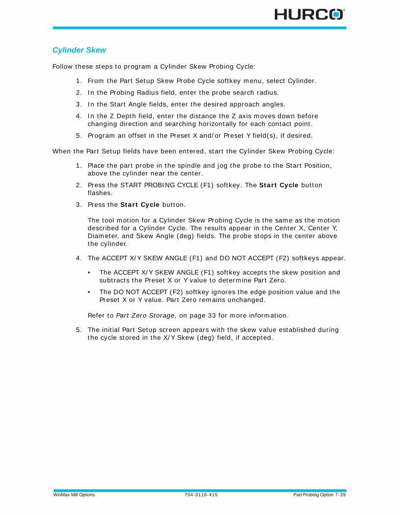
WinMax Mill Options 704-0116-415 Part Probing Option 7-39
Cylinder Skew
Follow these steps to program a Cylinder Skew Probing Cycle:
1. From the Part Setup Skew Probe Cycle softkey menu, select Cylinder.
2. In the Probing Radius field, enter the probe search radius.
3. In the Start Angle fields, enter the desired approach angles.
4. In the Z Depth field, enter the distance the Z axis moves down before changing direction and searching horizontally for each contact point.
5. Program an offset in the Preset X and/or Preset Y field(s), if desired.
When the Part Setup fields have been entered, start the Cylinder Skew Probing Cycle:
1. Place the part probe in the spindle and jog the probe to the Start Position, above the cylinder near the center.
2. Press the START PROBING CYCLE (F1) softkey. The Start Cycle button flashes.
3. Press the Start Cycle button.
The tool motion for a Cylinder Skew Probing Cycle is the same as the motion described for a Cylinder Cycle. The results appear in the Center X, Center Y, Diameter, and Skew Angle (deg) fields. The probe stops in the center above the cylinder.
4. The ACCEPT X/Y SKEW ANGLE (F1) and DO NOT ACCEPT (F2) softkeys appear.
• The ACCEPT X/Y SKEW ANGLE (F1) softkey accepts the skew position and subtracts the Preset X or Y value to determine Part Zero.
• The DO NOT ACCEPT (F2) softkey ignores the edge position value and the Preset X or Y value. Part Zero remains unchanged.
Refer to Part Zero Storage, on page 33 for more information.
5. The initial Part Setup screen appears with the skew value established during the cycle stored in the X/Y Skew (deg) field, if accepted.
7 - 40 Part Probing Option 704-0116-415 WinMax Mill Options
Rectangular Pocket Skew
Follow these steps to program a Rectangular Pocket Skew Cycle:
1. From the Part Setup Skew Probe Cycle softkey menu, select Rectangular Pocket Inside.
2. Program an offset for the Preset X and/or Preset Y field, if desired.
When the Part Setup fields have been entered, start the Rectangular Pocket Skew Probing Cycle:
1. Place the part probe in the spindle and jog the probe to the Start Position, inside the rectangular pocket.
2. Press the START PROBING CYCLE (F1) softkey. The Start Cycle button flashes.
3. Press the Start Cycle button.
The tool motion for a Rectangular Pocket Skew Probing Cycle is the same as the motion described for a Rectangular Pocket Cycle. The results are displayed on the screen in the Center X, Center Y, Length (X), Length (Y) and Skew Angle (deg) fields. The probe stops in the center of the pocket.
4. The ACCEPT X/Y SKEW ANGLE (F1) and DO NOT ACCEPT (F2) softkeys appear.
• The ACCEPT X/Y SKEW ANGLE (F1) softkey accepts the skew position and subtracts the Preset X or Y value to determine Part Zero.
• The DO NOT ACCEPT (F2) softkey ignores the edge position value and the Preset X or Y value. Part Zero remains unchanged.
Refer to Part Zero Storage, on page 33 for more information.
5. The initial Part Setup screen appears with the skew value established during the cycle stored in the X/Y Skew (deg) field, if accepted.
WinMax Mill Options 704-0116-415 Part Probing Option 7-41
Rectangular Solid Skew
Follow these steps to program a Rectangular Solid Skew Cycle:
1. From the Part Setup Skew Probe Cycle softkey menu, select Rectangular Solid Outside.
2. In the Probing Length X field, enter the pocket’s estimated X Length.
3. In the Probing Length Y field, enter the pocket’s estimated Y Length.
4. In the Z Depth field, enter the distance the Z axis moves downward before changing direction and moving to the edges for deflection.
5. Program an offset for the Preset X and/or Preset Y field, if desired.
When the Part Setup fields have been entered, start the Rectangular Solid Skew Probing Cycle:
1. Place the part probe in the spindle and jog the probe to the Start Position, above the rectangle near the center.
2. Press the START PROBING CYCLE (F1) softkey. The Start Cycle button flashes.
3. Press the Start Cycle button.
The tool motion for a Rectangular Solid Skew Probing Cycle is the same as the motion described for a Rectangular Solid Cycle. The results appear in the Center X, Center Y, Length (X), Length (Y), and Skew Angle (deg) fields. The probe moves to the center above the rectangle.
4. The ACCEPT X/Y SKEW ANGLE (F1) and DO NOT ACCEPT (F2) softkeys appear.
• The ACCEPT X/Y SKEW ANGLE (F1) softkey accepts the skew position and subtracts the Preset X or Y value to determine Part Zero.
• The DO NOT ACCEPT (F2) softkey ignores the edge position value and the Preset X or Y value. Part Zero remains unchanged.
Refer to Part Zero Storage, on page 33 for more information.
5. The initial Part Setup screen appears with the skew value established during the cycle stored in the X/Y Skew (deg) field, if accepted.
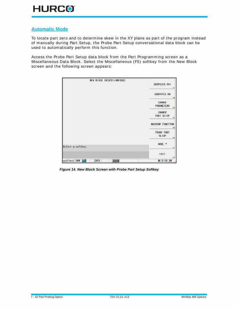
7 - 42 Part Probing Option 704-0116-415 WinMax Mill Options
Automatic Mode
To locate part zero and to determine skew in the XY plane as part of the program instead of manually during Part Setup, the Probe Part Setup conversational data block can be used to automatically perform this function.
Access the Probe Part Setup data block from the Part Programming screen as a Miscellaneous Data Block. Select the Miscellaneous (F5) softkey from the New Block screen and the following screen appears:
Figure 14. New Block Screen with Probe Part Setup Softkey
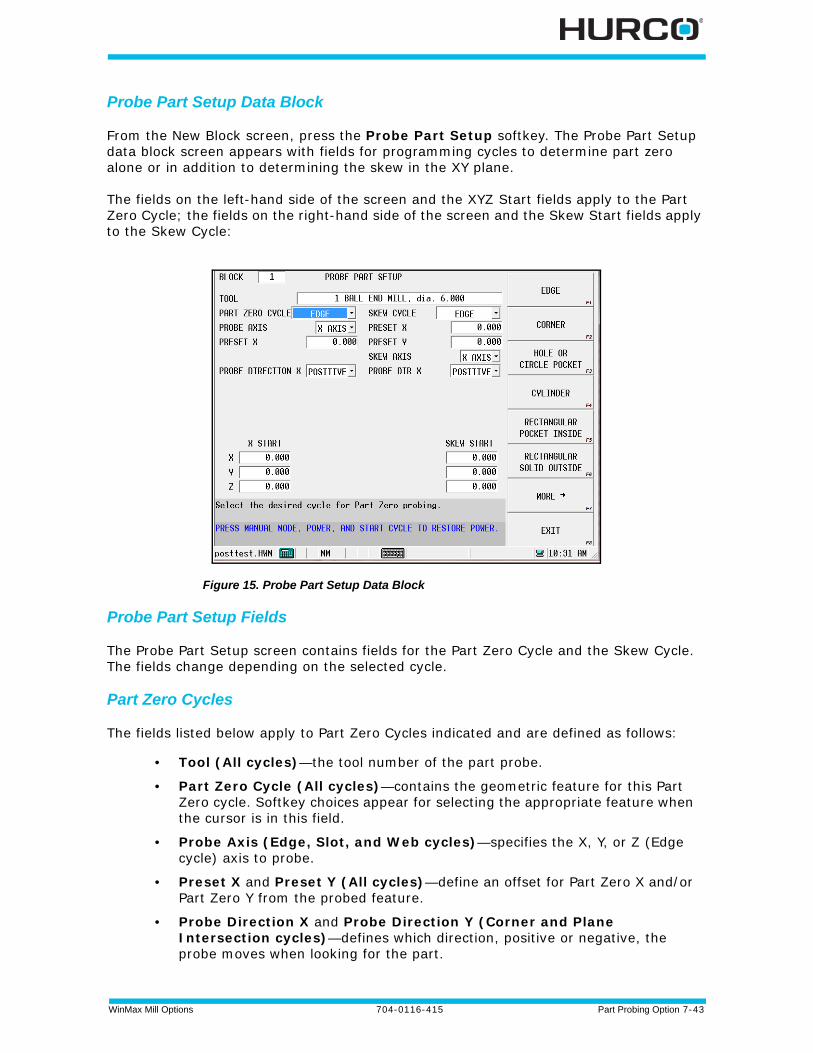
WinMax Mill Options 704-0116-415 Part Probing Option 7-43
Probe Part Setup Data Block
From the New Block screen, press the Probe Part Setup softkey. The Probe Part Setup data block screen appears with fields for programming cycles to determine part zero alone or in addition to determining the skew in the XY plane.
The fields on the left-hand side of the screen and the XYZ Start fields apply to the Part Zero Cycle; the fields on the right-hand side of the screen and the Skew Start fields apply to the Skew Cycle:
Figure 15. Probe Part Setup Data Block
Probe Part Setup Fields
The Probe Part Setup screen contains fields for the Part Zero Cycle and the Skew Cycle. The fields change depending on the selected cycle.
Part Zero Cycles
The fields listed below apply to Part Zero Cycles indicated and are defined as follows:
• Tool (All cycles)—the tool number of the part probe.
• Part Zero Cycle (All cycles)—contains the geometric feature for this Part Zero cycle. Softkey choices appear for selecting the appropriate feature when the cursor is in this field.
• Probe Axis (Edge, Slot, and Web cycles)—specifies the X, Y, or Z (Edge cycle) axis to probe.
• Preset X and Preset Y (All cycles)—define an offset for Part Zero X and/or Part Zero Y from the probed feature.
• Probe Direction X and Probe Direction Y (Corner and Plane Intersection cycles)—defines which direction, positive or negative, the probe moves when looking for the part.
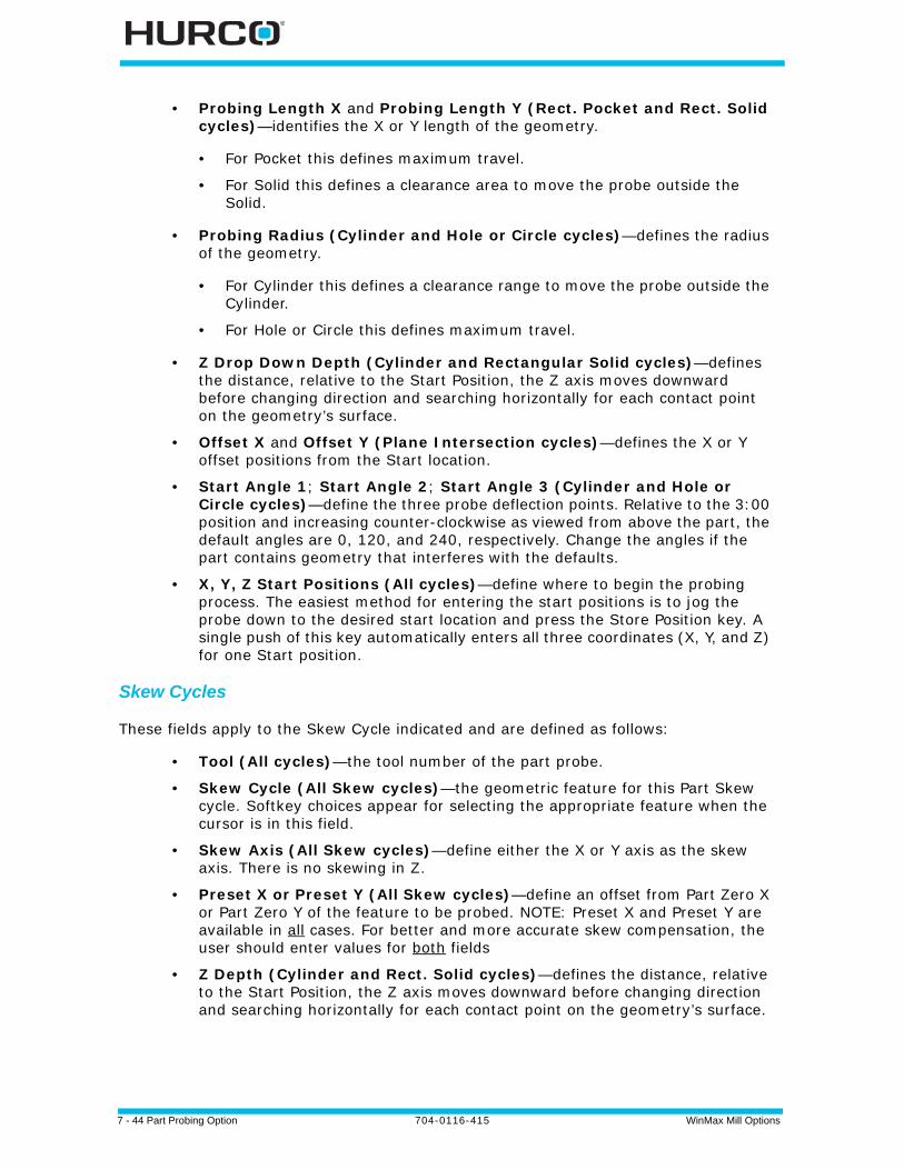
7 - 44 Part Probing Option 704-0116-415 WinMax Mill Options
• Probing Length X and Probing Length Y (Rect. Pocket and Rect. Solid cycles)—identifies the X or Y length of the geometry.
• For Pocket this defines maximum travel.
• For Solid this defines a clearance area to move the probe outside the Solid.
• Probing Radius (Cylinder and Hole or Circle cycles)—defines the radius of the geometry.
• For Cylinder this defines a clearance range to move the probe outside the Cylinder.
• For Hole or Circle this defines maximum travel.
• Z Drop Down Depth (Cylinder and Rectangular Solid cycles)—defines the distance, relative to the Start Position, the Z axis moves downward before changing direction and searching horizontally for each contact point on the geometry’s surface.
• Offset X and Offset Y (Plane Intersection cycles)—defines the X or Y offset positions from the Start location.
• Start Angle 1; Start Angle 2; Start Angle 3 (Cylinder and Hole or Circle cycles)—define the three probe deflection points. Relative to the 3:00 position and increasing counter-clockwise as viewed from above the part, the default angles are 0, 120, and 240, respectively. Change the angles if the part contains geometry that interferes with the defaults.
• X, Y, Z Start Positions (All cycles)—define where to begin the probing process. The easiest method for entering the start positions is to jog the probe down to the desired start location and press the Store Position key. A single push of this key automatically enters all three coordinates (X, Y, and Z) for one Start position.
Skew Cycles
These fields apply to the Skew Cycle indicated and are defined as follows:
• Tool (All cycles)—the tool number of the part probe.
• Skew Cycle (All Skew cycles)—the geometric feature for this Part Skew cycle. Softkey choices appear for selecting the appropriate feature when the cursor is in this field.
• Skew Axis (All Skew cycles)—define either the X or Y axis as the skew axis. There is no skewing in Z.
• Preset X or Preset Y (All Skew cycles)—define an offset from Part Zero X or Part Zero Y of the feature to be probed. NOTE: Preset X and Preset Y are available in all cases. For better and more accurate skew compensation, the user should enter values for both fields
• Z Depth (Cylinder and Rect. Solid cycles)—defines the distance, relative to the Start Position, the Z axis moves downward before changing direction and searching horizontally for each contact point on the geometry’s surface.
WinMax Mill Options 704-0116-415 Part Probing Option 7-45
• Probing Length X and Probing Length Y (Rect. Pocket and Rect. Solid cycles)—identifies the X or Y length of the geometry.
• For Pocket this defines maximum travel.
• For Solid this defines a clearance area to move the probe outside the Solid.
• Probing Radius (Cylinder and Hole or Circle cycles)—defines the radius of the geometry.
• For Cylinder this defines a clearance range to move the probe outside the Cylinder.
• For Hole or Circle this defines maximum travel.
• Probe Direction X or Y (depending on Skew Axis selection) (Edge cycles)—defines which direction, positive or negative, the probe moves when looking for the part.
• Skew Start Positions (All Skew cycles)—define where to begin the probing process. The easiest method for entering the start positions is to jog the probe down to the desired start location and press the Store Position key. A single push of this key automatically enters all three coordinates (X, Y, and Z) for one Start position.
Probe Part Setup Data Block Execution
When the program executes this data block, it will automatically probe the part and update Part Zero X, Part Zero Y, Probe Z and X/Y Skew. The data block may be placed anywhere in the part program except within a Pattern.
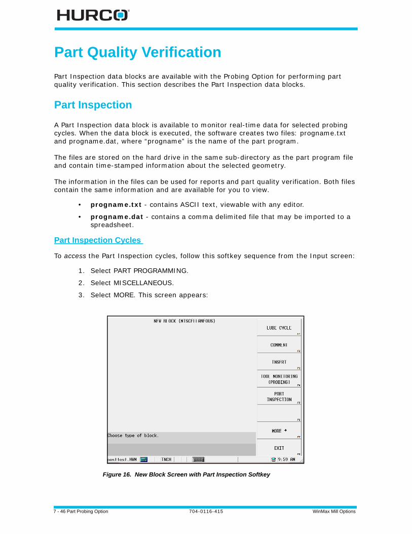
7 - 46 Part Probing Option 704-0116-415 WinMax Mill Options
Part Quality Verification
Part Inspection data blocks are available with the Probing Option for performing part quality verification. This section describes the Part Inspection data blocks.
Part Inspection
A Part Inspection data block is available to monitor real-time data for selected probing cycles. When the data block is executed, the software creates two files: progname.txt and progname.dat, where “progname” is the name of the part program.
The files are stored on the hard drive in the same sub-directory as the part program file and contain time-stamped information about the selected geometry.
The information in the files can be used for reports and part quality verification. Both files contain the same information and are available for you to view.
• progname.txt - contains ASCII text, viewable with any editor.
• progname.dat - contains a comma delimited file that may be imported to a spreadsheet.
Part Inspection Cycles
To access the Part Inspection cycles, follow this softkey sequence from the Input screen:
1. Select PART PROGRAMMING.
2. Select MISCELLANEOUS.
3. Select MORE. This screen appears:
Figure 16. New Block Screen with Part Inspection Softkey
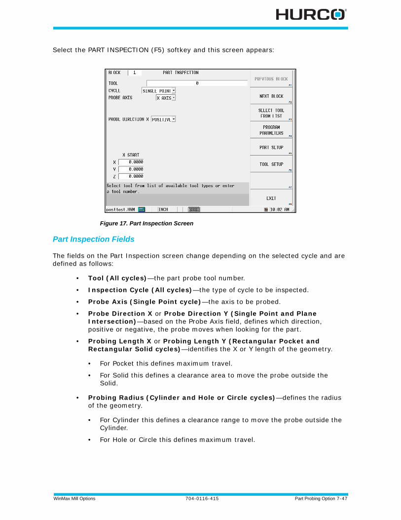
WinMax Mill Options 704-0116-415 Part Probing Option 7-47
Select the PART INSPECTION (F5) softkey and this screen appears:
Figure 17. Part Inspection Screen
Part Inspection Fields
The fields on the Part Inspection screen change depending on the selected cycle and are defined as follows:
• Tool (All cycles)—the part probe tool number.
• Inspection Cycle (All cycles)—the type of cycle to be inspected.
• Probe Axis (Single Point cycle)—the axis to be probed.
• Probe Direction X or Probe Direction Y (Single Point and Plane Intersection)—based on the Probe Axis field, defines which direction, positive or negative, the probe moves when looking for the part.
• Probing Length X or Probing Length Y (Rectangular Pocket and Rectangular Solid cycles)—identifies the X or Y length of the geometry.
• For Pocket this defines maximum travel.
• For Solid this defines a clearance area to move the probe outside the Solid.
• Probing Radius (Cylinder and Hole or Circle cycles)—defines the radius of the geometry.
• For Cylinder this defines a clearance range to move the probe outside the Cylinder.
• For Hole or Circle this defines maximum travel.
7 - 48 Part Probing Option 704-0116-415 WinMax Mill Options
• Z Depth (Cylinder and Rectangular Solid cycles)—defines the distance, relative to the Start Position, the Z axis moves downward before changing direction and searching horizontally for each contact point on the geometry’s surface.
• Offset X or Offset Y (Plane Intersection cycle)—defines the X or Y offset positions from the Start location.
• Start Angle1; Start Angle2; Start Angle3 (Cylinder and Hole or Circle cycles)—define the three probe deflection points. Relative to the 3:00 position and increasing counter-clockwise as viewed from above the part, the default angles are 0, 120, and 240, respectively. Change the angles if the part contains geometry that interferes with the defaults.
• X, Y, Z Start Positions (All cycles)—define where to begin the probing process. The easiest method for entering the start positions is to jog the probe down to the desired start location and press the Store Position key. A single push of this key automatically enters all three coordinates (X, Y, and Z) for one Start position.
Part Inspection Programming
Follow these steps to program a Part Inspection data block:
1. Enter the part probe tool number in the tool field.
2. When the cursor is on the Inspection Cycle field, the softkeys change. Select a cycle type for the Inspection Cycle field.
3. Program the remaining fields as described in the “Part Inspection Fields” section. The data block is stored with the program and executed automatically.
Part Inspection Files
When the Part Inspection data block is executed, the software automatically creates the part inspection files. The position data is presented in part relative coordinates.
• To view the files on your PC, first copy them to a disk in the floppy drive. Follow the steps for saving files to disk in the Programming Basics chapter of the Getting Started with WinMax manual.
It is not possible to view the Part Inspection files on the CNC.

WinMax Mill Options 704-0116-415 Part Probing Option 7-49
Here is a sample Part Inspection Probe.txt file:
****************************************** * PART INSPECTION DATA * ****************************************** Cylinder inspection (block # 3) executed 15:46:58 8/10/2000 Part Count = 4Center Diameter *********************************************************** X 16.7168 inches ( 424.607 mm)1.8878 inches ( 47.951 mm) Y 10.0995 inches ( 256.527 mm)
Single point inspection (block # 3) executed 9:50:31 8/11/2000 Part Count = 5 Point ******************************* X 10.3365 inches ( 262.548 mm) Y 10.3882 inches ( 263.860 mm) Z 14.2154 inches ( 361.070 mm)
Hole/circle inspection (block # 4) executed 9:50:45 8/11/2000 Part Count = 5 Center Diameter *********************************************************** X 9.3299 inches ( 236.978 mm)2.7577 inches ( 70.045 mm) Y 15.4572 inches ( 392.612 mm)
Cylinder inspection (block # 5) executed 9:51:02 8/11/2000 Part Count = 5 Center Diameter *********************************************************** X 16.7171 inches ( 424.613 mm)1.8883 inches ( 47.962 mm) Y 10.0996 inches ( 256.531 mm)
Rectangular pocket inspection (block # 6) executed 9:51:24 8/11/2000 Part Count = 5Center Length ************************************************************** X 14.4527 inches ( 367.099 mm)X 4.7259 inches ( 120.037 mm) Y 14.3001 inches ( 363.223 mm)Y 4.7258 inches ( 120.034 mm)
Rectangular solid inspection (block # 7) executed 9:51:47 8/11/2000 Part Count = 5 Center Length ************************************************************** X 9.4447 inches ( 239.895 mm)X 3.8176 inches ( 96.967 mm) Y 12.1092 inches ( 307.575 mm)Y 1.2629 inches ( 32.079 mm)
Plane intersect inspection (block # 8) executed 9:52:08 8/11/2000 Part Count = 5 Corner ******************************* X 7.7663 inches ( 197.264 mm) Y 13.2841 inches ( 337.417 mm)

7 - 50 Part Probing Option 704-0116-415 WinMax Mill Options
WinMax Mill Options 704-0116-415 Tool Probing Option 8-1
TOOL PROBING OPTION
Tool Probing measures Tool Cal Length (in Absolute Tool Length mode) or Zero Calibration (in Zero Calibration Mode) and Diameter/Diameter Wear using either a touch probe or a laser probe.
To get started, select the calibration mode you use:
Tool Probing in Absolute Tool Length Mode, on page 8 - 2
Tool Probing in Zero Calibration Mode, on page 8 - 8
Included in this chapter:
Tool Probing in Absolute Tool Length Mode, on page 8 - 2
Tool Probing in Zero Calibration Mode, on page 8 - 8
Tool Quality Monitoring, on page 8 - 14
Appendix A: Tool Probe Setup, on page 8 - 19
Appendix B: Tool Probe Calibration, on page 8 - 29
Appendix C: Probing Parameter Definitions, on page 8 - 33
If the probe is newly installed or has been relocated, it must be calibrated and the parameters set before probing. See Appendix A: Tool Probe Setup, on page 8 - 19 and Appendix B: Tool Probe Calibration, on page 8 - 29. These need to be done only when the probe is installed, replaced, or relocated, NOT each time it is used.
Calibration mode is set in Utilities/User Preferences/Tool Utilities and Settings. For more information, see Tool Calibration Modes, on page 4 - 16 in Getting Started with WinMax Mill.
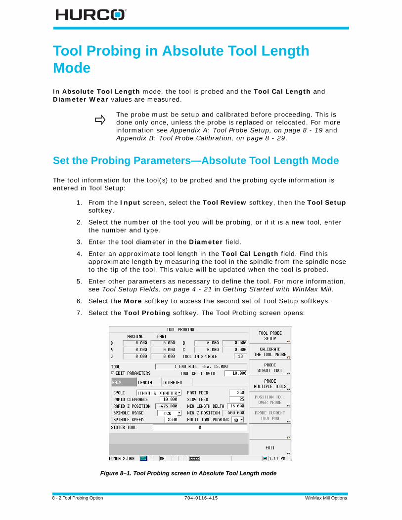
8 - 2 Tool Probing Option 704-0116-415 WinMax Mill Options
Tool Probing in Absolute Tool Length Mode
In Absolute Tool Length mode, the tool is probed and the Tool Cal Length and Diameter Wear values are measured.
Set the Probing Parameters—Absolute Tool Length Mode
The tool information for the tool(s) to be probed and the probing cycle information is entered in Tool Setup:
1. From the Input screen, select the Tool Review softkey, then the Tool Setup softkey.
2. Select the number of the tool you will be probing, or if it is a new tool, enter the number and type.
3. Enter the tool diameter in the Diameter field.
4. Enter an approximate tool length in the Tool Cal Length field. Find this approximate length by measuring the tool in the spindle from the spindle nose to the tip of the tool. This value will be updated when the tool is probed.
5. Enter other parameters as necessary to define the tool. For more information, see Tool Setup Fields, on page 4 - 21 in Getting Started with WinMax Mill.
6. Select the More softkey to access the second set of Tool Setup softkeys.
7. Select the Tool Probing softkey. The Tool Probing screen opens:
Figure 8–1. Tool Probing screen in Absolute Tool Length mode
The probe must be setup and calibrated before proceeding. This is done only once, unless the probe is replaced or relocated. For more information see Appendix A: Tool Probe Setup, on page 8 - 19 and Appendix B: Tool Probe Calibration, on page 8 - 29.

WinMax Mill Options 704-0116-415 Tool Probing Option 8-3
The current tool is displayed in the Tool field. The cycle parameters are displayed on the Main tab, and are read-only. Default values are set in the Tool Probing Cycle Defaults screen, see Tool Probing Cycle Defaults, on page 8 - 4. If you need to change one or more parameters for the current tool, check the Edit Parameters check box. (If you need to change a parameter for all tools, go back to the Tool Probing Cycle Defaults screen and make the change there.) The defaults should be set before proceeding with the probing cycle.
To set the remaining cycle parameters on the Main tab:
1. Select the type of probing cycle from the drop-down list in the Cycle field:
• Length—measures the Tool Cal Length. This value is automatically calculated by subtracting the probed Z location of the tool in spindle from the Z location of the probe stored in the Tool Measurement screen.
• Diameter—measures the actual tool diameter, and uses this value to determine the Diameter Wear and Radius Offset. For more information, see the Diameter Wear definition in Tool Setup Fields, on page 4 - 21 in Getting Started with WinMax Mill.
• Length & Diameter—measures both length and diameter.
2. Indicate Yes or No for Multi Tool Probing. Yes will include the current tool in multi-tool probing cycle.
3. Specify a Sister Tool to be used as a replacement if tool wear is out of tolerance. See Tool Quality Monitoring, on page 8 - 14.
The Length and Diameter tabs specify where these values are stored. These are also set in the Tool Probing Cycle Defaults screen, but can be changed here by selecting the Edit Parameters check box:
• Length—results are stored as either the Tool Length, or as a Tool Length Offset, or both. When stored as an offset, the Offset Number field appears where you can indicate the number in the Tool Offset table where the value is to be stored.
• Diameter—results are stored as either Diameter Wear, Tool Radius Offset, Diameter, Diameter Wear and Radius Offset, or Diameter and Radius Offset. When stored as an offset, the Offset Number field appears where you can indicate the number in the Tool Offset table where the value is to be stored.

8 - 4 Tool Probing Option 704-0116-415 WinMax Mill Options
Tool Probing Cycle Defaults
These are the Tool Probing Cycle defaults in Absolute Tool Length mode. For Zero Calibration Mode, see Tool Probing Cycle Defaults, on page 8 - 10.
Defaults for probing cycle parameters that infrequently need to be changed are set and stored in the Tool Probing Cycle Defaults screen. Once these parameters are set, they are automatically applied to each tool and do not have to be accessed again. However, if it is necessary to change one or more parameters for a specific tool, this is done in the Tool Probing screen. To access the Tool Probing Cycle Defaults screen:
1. From the Tool Probing screen, select the Tool Probe Setup softkey. The Tool Probe Parameters screen opens.
2. Select the Tool Probing Cycle Defaults softkey. The Tool Probing Cycle Defaults screen opens. Set the default values in this screen.
Figure 8–2. Tool Probing Cycle Defaults screen in Absolute Tool Length mode
3. Select the Spindle Usage. This is the direction the spindle turns during the probe cycle.
4. Enter a Spindle Speed, if Spindle Usage is CW or CCW.
5. Specify the Fast Feed and Slow Feed. These are the feedrates of the initial touch (Fast) and measurement touch (Slow).
6. Enter a value in the Rapid Clearance field. This is the distance above probe stylus or beam that determines Rapid Z Position.
7. Specify the Min Length Delta. This is the distance below the probe stylus or beam that the Z-axis is allowed to travel; determines the Min Z Position.
8. Specify the X and Y Length Offsets, if probing for length of a tool with its cutter offset from the center, for example, a face mill. Otherwise, leave at 0.0.
9. Specify Z Drop Down Depth for diameter. This is the distance the tool drops down from the point where the tool tip touches the top of the probe, when probing for diameter. Value is always negative.
10.Specify Spindle Clearance, the distance between the tool and the probe

WinMax Mill Options 704-0116-415 Tool Probing Option 8-5
when the tool drops down for diameter probing.
11.Specify how to store the Length and Diameter results:
• Length can be stored as Length, Offset, or both.
• Diameter can be stored as:
• Diameter Wear
• Radius offset
• Diameter
• Diameter Wear and Radius Offset
• Diameter and Radius Offset
Select the Apply Defaults to Current Tool softkey to apply these defaults to the tool currently being edited. You only need to do this when you first set the defaults or when you change any of the values.
Select the Apply Defaults to All Tools softkey to apply these defaults to all tools in the active program’s tool setup, or to the entire tool library if using the Tool and Material Library option.
Select Exit twice to return to the Tool Probing screen.
Run the Probe Cycle
When the cycle parameters are set, you are ready to run the probe cycle:
1. Select the Probe Single Tool softkey.
2. Enter the Tool Number to probe. The following sequence occurs for length probing:
a. The Start Cycle button flashes and a prompt to press Start appears.b. Press the Start Cycle button to continue.
• f the tool to be probed is not in the spindle, a tool change occurs.
• If the tool to be probed is not in the magazine, the software prompts for the tool.
• The spindle operates as specified in the Spindle Usage field in Tool Setup.
c. The Z axis moves downward at rapid feed until it reaches Rapid Z Position. Axis Feedrate Override is active during this move.
• The Z axis continues moving at Fast Feed until a probe deflection occurs.
• If the probe reaches Min Z Position prior to deflection, an error message appears. The value may need to be adjusted to correct the problem.
If the tool that you wish to probe is already in the spindle, select the Probe Current Tool Now softkey.
To probe multiple tools, see Probe Multiple Tools, on page 8 - 7.
8 - 6 Tool Probing Option 704-0116-415 WinMax Mill Options
d. The tool touches the probe (or breaks the beam for laser).
e. For a touch probe:
• The tool retracts slightly (at Slow Feed) and makes three touches (deflections) at Slow Feed. The average length of these deflections is used to determine the tool length.
For a laser probe:
• The tool retracts up out of the beam (at Slow Feed) until the beam is uninterrupted. The measurement is always taken when the tool moves out of the beam. The average of these readings is used to determine the tool length.
3. The Probe Single Tool cycle is now complete for length. Select the Exit softkey to return to the initial Tool Setup screen. The Tool Cal Length field is updated and the “P” designator appears.
Continue with the next step to probe the tool’s diameter.
4. If you entered an estimate of the tool’s diameter in the Diameter field and selected Diameter or Length & Diameter in the Cycle field on the Tool Probing screen, the probe cycle continues with the tool Diameter sequence:
a. The tool retracts just above the probe and moves to one side at Spindle Clearance.
b. The tool drops down to Z Drop Down Depth, below the top of the tool probe stylus or beam, and moves toward the probe.
c. The tool touches the probe (or breaks the beam for a laser).
d. For a touch probe:
• The tool retracts slightly (at Slow Feed) and makes three touches (deflections) at Slow Feed. The average of these deflections is stored for calculation after the other side of the tool is probed.
For a laser probe:
• The tool retracts out of the beam (at Slow Feed) until the beam is uninterrupted. The measurement is always taken when the tool moves out of the beam. The average of these readings is stored for calculation after the other side of the tool is probed.
e. The tool moves up and over to the other side of the stylus or beam (to Spindle Clearance), and steps a-d are repeated from the other side of the probe.
f. The two readings (one from each side of the probe) are used to determine the actual diameter of the tool.
5. The actual probed diameter is subtracted from the tool diameter entered in Tool Setup, and this value appears in the Diameter Wear field on the Tool Setup screen with the “P” designator.
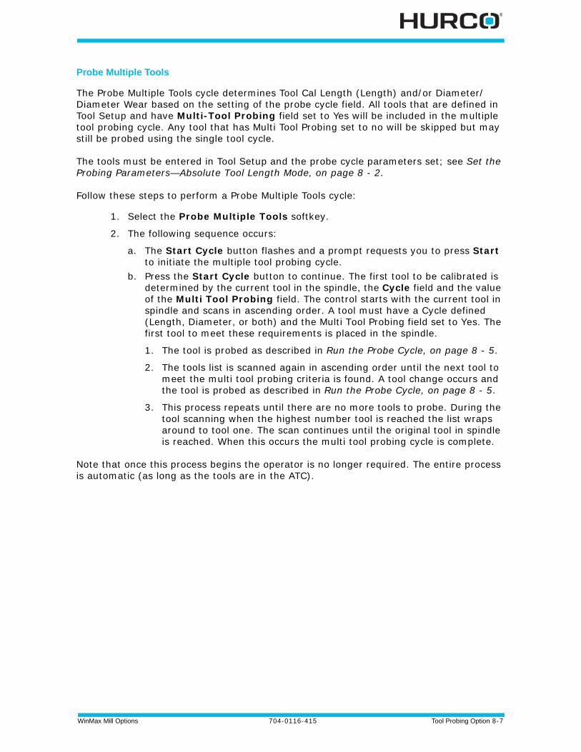
WinMax Mill Options 704-0116-415 Tool Probing Option 8-7
Probe Multiple Tools
The Probe Multiple Tools cycle determines Tool Cal Length (Length) and/or Diameter/Diameter Wear based on the setting of the probe cycle field. All tools that are defined in Tool Setup and have Multi-Tool Probing field set to Yes will be included in the multiple tool probing cycle. Any tool that has Multi Tool Probing set to no will be skipped but may still be probed using the single tool cycle.
The tools must be entered in Tool Setup and the probe cycle parameters set; see Set the Probing Parameters—Absolute Tool Length Mode, on page 8 - 2.
Follow these steps to perform a Probe Multiple Tools cycle:
1. Select the Probe Multiple Tools softkey.
2. The following sequence occurs:
a. The Start Cycle button flashes and a prompt requests you to press Start to initiate the multiple tool probing cycle.
b. Press the Start Cycle button to continue. The first tool to be calibrated is determined by the current tool in the spindle, the Cycle field and the value of the Multi Tool Probing field. The control starts with the current tool in spindle and scans in ascending order. A tool must have a Cycle defined (Length, Diameter, or both) and the Multi Tool Probing field set to Yes. The first tool to meet these requirements is placed in the spindle.
1. The tool is probed as described in Run the Probe Cycle, on page 8 - 5.
2. The tools list is scanned again in ascending order until the next tool to meet the multi tool probing criteria is found. A tool change occurs and the tool is probed as described in Run the Probe Cycle, on page 8 - 5.
3. This process repeats until there are no more tools to probe. During the tool scanning when the highest number tool is reached the list wraps around to tool one. The scan continues until the original tool in spindle is reached. When this occurs the multi tool probing cycle is complete.
Note that once this process begins the operator is no longer required. The entire process is automatic (as long as the tools are in the ATC).
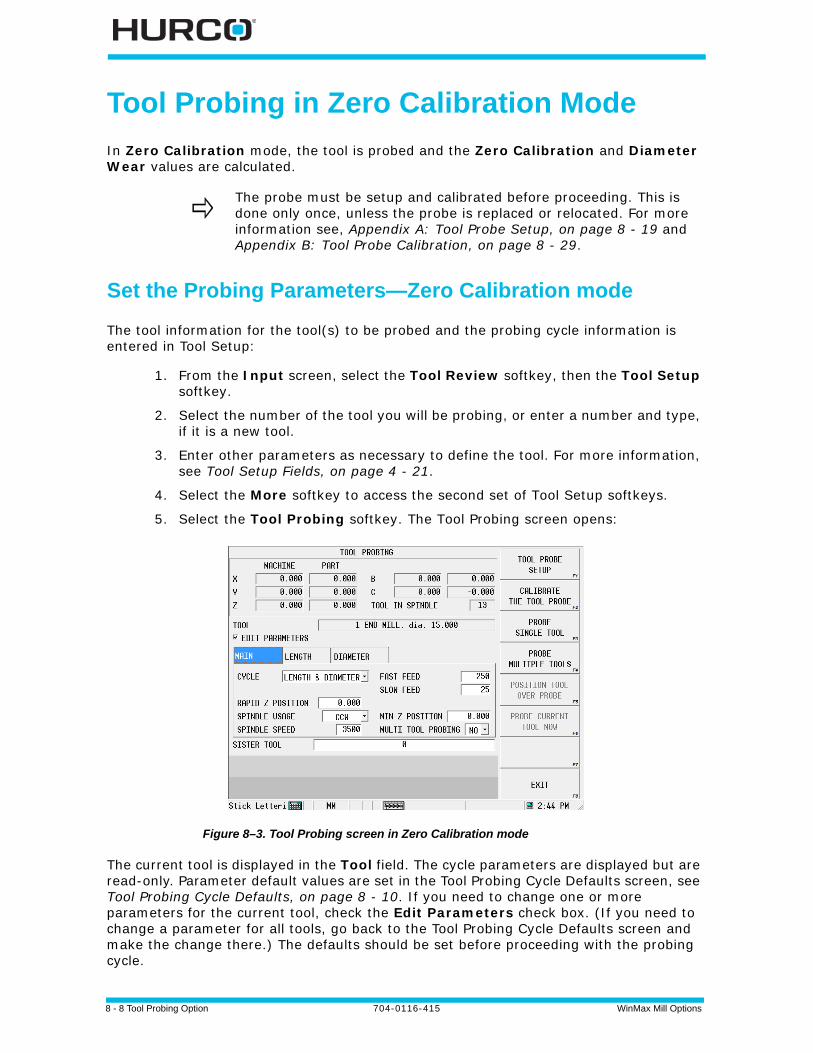
8 - 8 Tool Probing Option 704-0116-415 WinMax Mill Options
Tool Probing in Zero Calibration Mode
In Zero Calibration mode, the tool is probed and the Zero Calibration and Diameter Wear values are calculated.
Set the Probing Parameters—Zero Calibration mode
The tool information for the tool(s) to be probed and the probing cycle information is entered in Tool Setup:
1. From the Input screen, select the Tool Review softkey, then the Tool Setup softkey.
2. Select the number of the tool you will be probing, or enter a number and type, if it is a new tool.
3. Enter other parameters as necessary to define the tool. For more information, see Tool Setup Fields, on page 4 - 21.
4. Select the More softkey to access the second set of Tool Setup softkeys.
5. Select the Tool Probing softkey. The Tool Probing screen opens:
Figure 8–3. Tool Probing screen in Zero Calibration mode
The current tool is displayed in the Tool field. The cycle parameters are displayed but are read-only. Parameter default values are set in the Tool Probing Cycle Defaults screen, see Tool Probing Cycle Defaults, on page 8 - 10. If you need to change one or more parameters for the current tool, check the Edit Parameters check box. (If you need to change a parameter for all tools, go back to the Tool Probing Cycle Defaults screen and make the change there.) The defaults should be set before proceeding with the probing cycle.
The probe must be setup and calibrated before proceeding. This is done only once, unless the probe is replaced or relocated. For more information see, Appendix A: Tool Probe Setup, on page 8 - 19 and Appendix B: Tool Probe Calibration, on page 8 - 29.
WinMax Mill Options 704-0116-415 Tool Probing Option 8-9
To set the remaining cycle parameters for the current tool:
1. Select the type of probing cycle from the drop-down list in the Cycle field:
• Length—measures the tool length (as Zero Calibration). This value is automatically calculated using the stored internal value and the Probe Z value obtained from probe calibration.
• Diameter—measures the actual tool diameter, and uses this value to determine the Diameter Wear. For more information, see the Diameter Wear definition in Tool Setup Fields, on page 4 - 21.
• Length & Diameter—measures both length and diameter.
2. Ensure the correct value has been entered in the Rapid Z Position field. This is the position just above the contact point of the probe that the tool rapids down to before continuing downward at Fast Feed for the initial touch.
To set Rapid Z Position, use the remote jog unit to jog the part probe to a point just above the contact point of the tool probe and select the Set Position softkey, or type in a value for the Rapid Z Position field. (With the cursor in this field, the Position Tool Over Probe softkey can be used to position the part probe over the tool probe before jogging Z to the desired position.)
3. Specify the Min Z Position. This is the lowest position that Z will be allowed to travel during the probe cycle.
4. Indicate Yes or No for Multi Tool Probing. Yes will include the current tool in multi-tool probe cycle.
5. Specify a Sister Tool to be used for as a replacement if tool wear is out of tolerance. See Tool Quality Monitoring, on page 8 - 14.
6. The Length and Diameter tabs contain the values for these parameters set in the Tool Probing Cycle Defaults screen, and may be changed here for the current tool; check the Edit Parameters check box.
Determine Probe Z
The Probe Z value of the part needs to be set whenever a new part is placed on the table. The Zero Calibration value of the tool is calculated using the new Probe Z value, the stored internal value (from tool probe calibration), and the probed tool length.
If you are using a reference tool to calibrate the tool probe:
1. From the Input screen, select the Part Setup softkey to open the Part Setup screen.
2. With the cursor in the Probe Z field, touch off the top of the part with the part probe or reference tool.
3. Select the Store Machine Position softkey. This value is stored in Probe Z.
If you are using a part probe to calibrate the tool probe, use the part probe Z Edge cycle to determine Probe Z. See Edge, on page 7 - 14 in Part Probing.
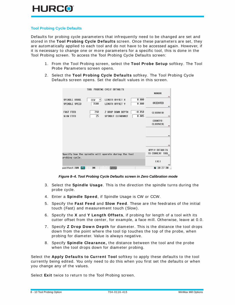
8 - 10 Tool Probing Option 704-0116-415 WinMax Mill Options
Tool Probing Cycle Defaults
Defaults for probing cycle parameters that infrequently need to be changed are set and stored in the Tool Probing Cycle Defaults screen. Once these parameters are set, they are automatically applied to each tool and do not have to be accessed again. However, if it is necessary to change one or more parameters for a specific tool, this is done in the Tool Probing screen. To access the Tool Probing Cycle Defaults screen:
1. From the Tool Probing screen, select the Tool Probe Setup softkey. The Tool Probe Parameters screen opens.
2. Select the Tool Probing Cycle Defaults softkey. The Tool Probing Cycle Defaults screen opens. Set the default values in this screen.
Figure 8–4. Tool Probing Cycle Defaults screen in Zero Calibration mode
3. Select the Spindle Usage. This is the direction the spindle turns during the probe cycle.
4. Enter a Spindle Speed, if Spindle Usage is CW or CCW.
5. Specify the Fast Feed and Slow Feed. These are the feedrates of the initial touch (Fast) and measurement touch (Slow).
6. Specify the X and Y Length Offsets, if probing for length of a tool with its cutter offset from the center, for example, a face mill. Otherwise, leave at 0.0.
7. Specify Z Drop Down Depth for diameter. This is the distance the tool drops down from the point where the tool tip touches the top of the probe, when probing for diameter. Value is always negative.
8. Specify Spindle Clearance, the distance between the tool and the probe when the tool drops down for diameter probing.
Select the Apply Defaults to Current Tool softkey to apply these defaults to the tool currently being edited. You only need to do this when you first set the defaults or when you change any of the values.
Select Exit twice to return to the Tool Probing screen.

WinMax Mill Options 704-0116-415 Tool Probing Option 8-11
Run the Probe Cycle
When the Probe Z value is set, return to the Tool Setup/Tool Probing screen
1. Select the Probe Single Tool softkey.
2. Enter the Tool Number to probe. The following sequence occurs for length probing:
a. The Start Cycle button flashes and a prompt to press Start appears.b. Press the Start Cycle button to continue.
• f the tool to be probed is not in the spindle, a tool change occurs.
• If the tool to be probed is not in the magazine, the software prompts for the tool.
• The spindle operates as specified in the Spindle Usage field in Tool Setup.
c. The Z axis moves downward at rapid feed until it reaches Rapid Z Position. Axis Feedrate Override is active during this move.
• The Z axis continues moving at Fast Feed until a probe deflection occurs.
• If the probe reaches Min Z Position prior to deflection, an error message appears. The value may need to be adjusted to correct the problem.
d. The tool touches the probe (or breaks the beam for laser).
e. For a touch probe:
• The tool retracts slightly (at Slow Feed) and makes three touches (deflections) at Slow Feed. The average length of these deflections is used to determine the tool length.
For a laser probe:
• The tool retracts up out of the beam (at Slow Feed) until the beam is uninterrupted. The measurement is always taken when the tool moves out of the beam. The average of these readings is used to determine the tool length.
3. The Probe Single Tool cycle is now complete for length. Select the Exit softkey to return to the initial Tool Setup screen. The Zero Calibration field is updated and the “P” designator appears.
Continue with the next step to probe the tool’s diameter.
If the tool that you wish to probe is already in the spindle, select the Probe Current Tool softkey.
To probe multiple tools, see Probe Multiple Tools, on page 8 - 7.

8 - 12 Tool Probing Option 704-0116-415 WinMax Mill Options
4. If you entered an estimate of the tool’s diameter in the Diameter field and selected Diameter or Length & Diameter in the Cycle field on the Tool Probing screen, the probe cycle continues with the tool Diameter sequence:
a. The tool retracts just above the probe and moves to one side at Spindle Clearance.
b. The tool drops down to Z Drop Down Depth, below the top of the tool probe stylus or beam, and moves toward the probe.
c. The tool touches the probe (or breaks the beam for a laser).
d. For a touch probe:
• The tool retracts slightly (at Slow Feed) and makes three touches (deflections) at Slow Feed. The average of these deflections is stored for calculation after the other side of the tool is probed.
For a laser probe:
• The tool retracts out of the beam (at Slow Feed) until the beam is uninterrupted. The measurement is always taken when the tool moves out of the beam. The average of these readings is stored for calculation after the other side of the tool is probed.
e. The tool moves up and over to the other side of the stylus or beam (to Spindle Clearance), and steps a-d are repeated from the other side of the probe.
f. The two readings (one from each side of the probe) are used to determine the actual diameter of the tool.
5. The actual probed diameter is subtracted from the tool diameter entered in Tool Setup, and this value appears in the Diameter Wear field on the Tool Setup screen with the “P” designator.
WinMax Mill Options 704-0116-415 Tool Probing Option 8-13
Probe Multiple Tools
The Probe Multiple Tools cycle determines Zero Calibration and/or Diameter Wear (Diameter) based on the setting of the probe cycle field. All tools that are defined in Tool Setup and have Multi-Tool Probing field set to Yes will be included in the multiple tool probing cycle. Any tool that has Multi Tool Probing set to no will be skipped but may still be probed using the single tool cycle.
The tools must be entered in Tool Setup and the probe cycle parameters set; see Set the Probing Parameters—Zero Calibration mode, on page 8 - 8.
Follow these steps to perform a Probe Multiple Tools cycle:
1. Select the Probe Multiple Tools softkey.
2. The following sequence occurs:
a. The Start Cycle button flashes and a prompt requests you to press Start to initiate the multiple tool probing cycle.
b. Press the Start Cycle button to continue. The first tool to be calibrated is determined by the current tool in the spindle, the Cycle field and the value of the Multi Tool Probing field. The control starts with the current tool in spindle and scans in ascending order. A tool must have a Cycle defined (Length, Diameter, or both) and the Multi Tool Probing field set to Yes. The first tool to meet these requirements is placed in the spindle.
1. The tool is probed as described in Run the Probe Cycle, on page 8 - 11.
2. The tools list is scanned again in ascending order until the next tool to meet the multi tool probing criteria is found. A tool change occurs and the tool is probed as described in Run the Probe Cycle, on page 8 - 11.
3. This process repeats until there are no more tools to probe. During the tool scanning when the highest number tool is reached the list wraps around to tool one. The scan continues until the original tool in spindle is reached. When this occurs the multi tool probing cycle is complete.
Note that once this process begins the operator is no longer required. The entire process is automatic (as long as the tools are in the ATC).
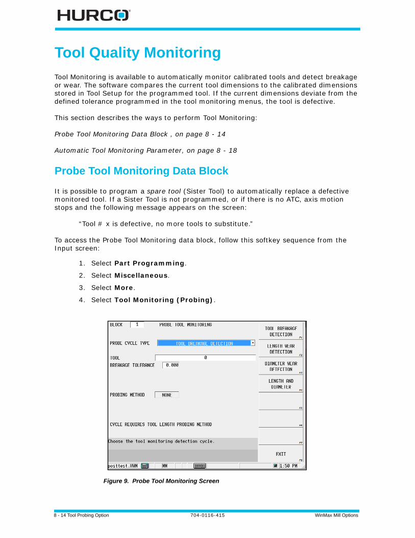
8 - 14 Tool Probing Option 704-0116-415 WinMax Mill Options
Tool Quality Monitoring
Tool Monitoring is available to automatically monitor calibrated tools and detect breakage or wear. The software compares the current tool dimensions to the calibrated dimensions stored in Tool Setup for the programmed tool. If the current dimensions deviate from the defined tolerance programmed in the tool monitoring menus, the tool is defective.
This section describes the ways to perform Tool Monitoring:
Probe Tool Monitoring Data Block , on page 8 - 14
Automatic Tool Monitoring Parameter, on page 8 - 18
Probe Tool Monitoring Data Block
It is possible to program a spare tool (Sister Tool) to automatically replace a defective monitored tool. If a Sister Tool is not programmed, or if there is no ATC, axis motion stops and the following message appears on the screen:
“Tool # x is defective, no more tools to substitute.”
To access the Probe Tool Monitoring data block, follow this softkey sequence from the Input screen:
1. Select Part Programming.
2. Select Miscellaneous.
3. Select More.
4. Select Tool Monitoring (Probing).
Figure 9. Probe Tool Monitoring Screen
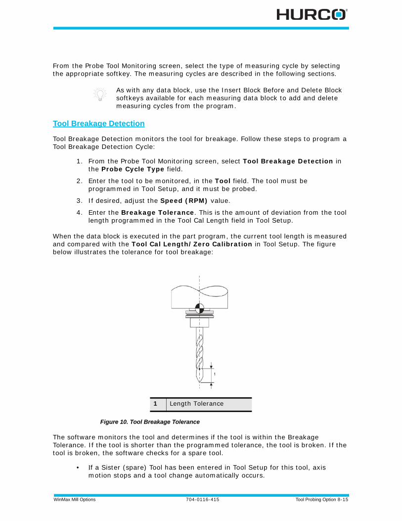
WinMax Mill Options 704-0116-415 Tool Probing Option 8-15
From the Probe Tool Monitoring screen, select the type of measuring cycle by selecting the appropriate softkey. The measuring cycles are described in the following sections.
Tool Breakage Detection
Tool Breakage Detection monitors the tool for breakage. Follow these steps to program a Tool Breakage Detection Cycle:
1. From the Probe Tool Monitoring screen, select Tool Breakage Detection in the Probe Cycle Type field.
2. Enter the tool to be monitored, in the Tool field. The tool must be programmed in Tool Setup, and it must be probed.
3. If desired, adjust the Speed (RPM) value.
4. Enter the Breakage Tolerance. This is the amount of deviation from the tool length programmed in the Tool Cal Length field in Tool Setup.
When the data block is executed in the part program, the current tool length is measured and compared with the Tool Cal Length/Zero Calibration in Tool Setup. The figure below illustrates the tolerance for tool breakage:
Figure 10. Tool Breakage Tolerance
The software monitors the tool and determines if the tool is within the Breakage Tolerance. If the tool is shorter than the programmed tolerance, the tool is broken. If the tool is broken, the software checks for a spare tool.
• f a Sister (spare) Tool has been entered in Tool Setup for this tool, axis motion stops and a tool change automatically occurs.
As with any data block, use the Insert Block Before and Delete Block softkeys available for each measuring data block to add and delete measuring cycles from the program.
1 Length Tolerance

8 - 16 Tool Probing Option 704-0116-415 WinMax Mill Options
• If there is no Sister Tool programmed for this tool, or if there is no ATC, axis motion will stop and a message appears telling you to change tools.
These are the fields when Tool Breakage Detection is selected for Probe Cycle Type:
• Probe Cycle Type—contains the type of cycle selected from the Probe Tool Monitoring menu.
• Tool—the number and description of the tool to be monitored.
• Breakage Tolerance—the amount of deviation from the tool length programmed in the Tool Cal Length field in Tool Setup.
• Speed (RPM)—contains the spindle speed value defined in Tool Setup for this tool. This value can be adjusted in Tool Monitoring.
• Direction—contains the direction the spindle will turn.
• Probing Method—displays the method used: Length, Diameter, Length & Diameter. Field is read-only.
• Spindle Usage—the spindle direction. Field is read-only.
• Sister Tool—contains the number and description of the tool defined in Tool Setup as the Sister (spare) for this tool. This field is read-only.
Tool Wear Detection
To monitor tool length and/or diameter wear, select from the following Probe Cycle Type choices:
• Tool Length Wear Detection
• Tool Diameter Wear Detection
• Tool Length & Diameter Wear Detection
Follow these steps to program a Tool Wear Detection Cycle:
1. From the Probe Tool Monitoring screen, select the Probe Cycle Type.
2. Enter the Tool to be monitored. The tool must be programmed in Tool Setup, and it must be calibrated.
3. Enter Length Tolerance or Diameter Tolerance, or both if monitoring both length and diameter.
When the data block is executed in the part program, the current tool length is measured and compared with the tool length or diameter tolerance, or both if monitoring both length and diameter. The figure below illustrates the tool wear tolerances:
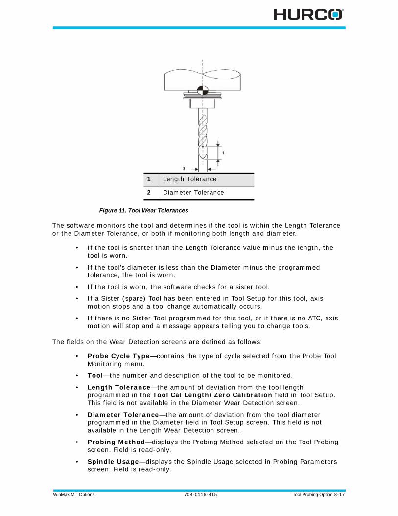
WinMax Mill Options 704-0116-415 Tool Probing Option 8-17
Figure 11. Tool Wear Tolerances
The software monitors the tool and determines if the tool is within the Length Tolerance or the Diameter Tolerance, or both if monitoring both length and diameter.
• If the tool is shorter than the Length Tolerance value minus the length, the tool is worn.
• If the tool’s diameter is less than the Diameter minus the programmed tolerance, the tool is worn.
• If the tool is worn, the software checks for a sister tool.
• If a Sister (spare) Tool has been entered in Tool Setup for this tool, axis motion stops and a tool change automatically occurs.
• If there is no Sister Tool programmed for this tool, or if there is no ATC, axis motion will stop and a message appears telling you to change tools.
The fields on the Wear Detection screens are defined as follows:
• Probe Cycle Type—contains the type of cycle selected from the Probe Tool Monitoring menu.
• Tool—the number and description of the tool to be monitored.
• Length Tolerance—the amount of deviation from the tool length programmed in the Tool Cal Length/Zero Calibration field in Tool Setup. This field is not available in the Diameter Wear Detection screen.
• Diameter Tolerance—the amount of deviation from the tool diameter programmed in the Diameter field in Tool Setup screen. This field is not available in the Length Wear Detection screen.
• Probing Method—displays the Probing Method selected on the Tool Probing screen. Field is read-only.
• Spindle Usage—displays the Spindle Usage selected in Probing Parameters screen. Field is read-only.
1 Length Tolerance
2 Diameter Tolerance
8 - 18 Tool Probing Option 704-0116-415 WinMax Mill Options
• Sister Tool—contains the number and description of the tool defined in Tool Setup as the Sister (spare) for this tool. This field is read-only.
Automatic Tool Monitoring Parameter
Another method of monitoring tool quality is the Probing Parameter’s Automatic Tool Monitoring field. This setup automatically checks every probed tool for wear immediately after the tool change.
To set this parameter to automatically monitor tool quality:
1. From the Input screen, select the Program Parameters softkey.
2. Select the Probing tab.
3. Set the Automatic Tool Monitoring parameter to Yes.
4. Specify the Length Tolerance. This is the amount of deviation from the tool length programmed in Tool Setup screen.
5. Specify the Diameter Tolerance. This is the amount of deviation from the tool diameter programmed in Tool Setup screen.
The software monitors the tool and determines if the tool is within the Length Tolerance or the Diameter Tolerance, or both if monitoring both length and diameter.
• If the tool is shorter than the Length Tolerance value minus the length, the tool is worn.
• If the tool’s diameter is less than the Diameter minus the programmed tolerance, the tool is worn.
• If the tool is worn, the software checks for a sister tool.
• If a Sister (spare) Tool has been entered in Tool Setup for this tool, axis motion stops and a tool change automatically occurs.
• If there is no Sister Tool programmed for this tool, or if there is no ATC, axis motion will stop and a message appears telling you to change tools.

WinMax Mill Options 704-0116-415 Tool Probing Option 8-19
Appendix A: Tool Probe Setup
Tool probe setup parameters provide critical information on how the machine will use the probes. The parameters include fields specific to programming a touch probe or a laser probe.
From Tool Setup, select the Tool Probing softkey, then the Tool Probe Setup softkey. The Tool Probe Parameters screen opens. From here, you can access the parameters for the type of probe you select, either Touch Probe or Laser Probe.
Touch Probe Parameters
Select the Touch Probe Parameters softkey to access the touch tool probe fields. The following screen appears:
Figure 8–1. Touch Probe Parameters
Tool Setup Touch Probe Parameters are defined as follows:
• Type—indicates the type of tool probe. If a tool probe is not present, the remaining tool probe parameters are not used.
• Contact Point X and Contact Point Y (touch tool probe only)—indicates the X and Y location (in machine coordinates) of the tool probe. When the machine is at this location, a tool will touch the center of the tool probe stylus. To enter these values easily, insert a tool in the spindle and jog down to the tip of the probe. When the tool tip is centered over the stylus, press the Store Position key on the jog controls.
Tool probe setup parameters should only be adjusted when a tool probe is newly installed, relocated, or when probing feedrates are changed.
8 - 20 Tool Probing Option 704-0116-415 WinMax Mill Options
• Setup Fast Feed —indicates the feed rate to use for setup moves near the probe. For example, when dropping down next to the probe to measure diameter, the drop down move uses this feed rate. This value is also used for calibrating the probe and the initial touch when determining deflection offsets.
• Retract Feed — indicates the feed rate to use when retracting away from the probe immediately after a deflection. This value is also used for the slow moves when determining deflection offsets.
• Repetitions—specifies the number of Slow Feed touches when touching tools to the probe. You can program up to 99 repetitions to get the average length and diameter of the tool.
• Probing Axis—specifies the axis of deflection in the X/Y plane. Orientation of the probe will determine if it deflects along the X axis or the Y axis. It is assumed the probe will always deflect along the Z axis.
• Stylus Width (touch tool probe only)— specifies the width of the probe’s stylus along the Probing Axis.
• Max Spread—the deviation (difference) between the minimum and maximum probe readings. If the deviation is greater than the Max Spread value, an error message appears.
• INIT Retract—scales the initial retract move after a deflection.
• INCR Retract—scales the incremental moves that may be required if the probe is still deflected after the initial move.
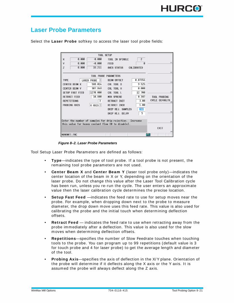
WinMax Mill Options 704-0116-415 Tool Probing Option 8-21
Laser Probe Parameters
Select the Laser Probe softkey to access the laser tool probe fields:
Figure 8–2. Laser Probe Parameters
Tool Setup Laser Probe Parameters are defined as follows:
• Type—indicates the type of tool probe. If a tool probe is not present, the remaining tool probe parameters are not used.
• Center Beam X and Center Beam Y (laser tool probe only)—indicates the center location of the beam in X or Y, depending on the orientation of the laser probe. Do not change this value after the Laser Tool Calibration cycle has been run, unless you re-run the cycle. The user enters an approximate value then the laser calibration cycle determines the precise location.
• Setup Fast Feed —indicates the feed rate to use for setup moves near the probe. For example, when dropping down next to the probe to measure diameter, the drop down move uses this feed rate. This value is also used for calibrating the probe and the initial touch when determining deflection offsets.
• Retract Feed — indicates the feed rate to use when retracting away from the probe immediately after a deflection. This value is also used for the slow moves when determining deflection offsets.
• Repetitions—specifies the number of Slow Feedrate touches when touching tools to the probe. You can program up to 99 repetitions (default value is 3 for touch probe and 4 for laser probe) to get the average length and diameter of the tool.
• Probing Axis—specifies the axis of deflection in the X/Y plane. Orientation of the probe will determine if it deflects along the X axis or the Y axis. It is assumed the probe will always deflect along the Z axis.
8 - 22 Tool Probing Option 704-0116-415 WinMax Mill Options
• Beam Offset (laser tool probe only)—displays the width of the beam based on + and - trigger points. This field is updated after running the Determine Laser Beam Offset cycle. It may be adjusted by the user to optimize performance.
• Cal Tool D (laser tool probe only)—contains the diameter (D) of the Laser Calibration Tool. This value can be obtained by measuring the diameter of a precision dowel or a laser calibration tool.
• Cal Tool H (laser tool probe only)—contains the height (H) of the Laser Calibration Tool. This value can be obtained by measuring the height of a precision dowel or a laser calibration tool.
• Cal Tool L (laser tool probe only)—contains the length (L) of the Laser Calibration Tool. This value can be obtained by measuring the length of a precision dowel or a laser calibration tool.
• Max Spread—The deviation (difference) between the minimum and maximum probe readings. If the deviation is greater than the Max Spread value, an error message appears.
• INIT Retract—scales the initial retract move after a deflection.
• INCR Retract—scales the incremental moves that may be required if the probe is still deflected after the initial move.
• Drip Rej. Samples—enter the number of samples for coolant drip rejection. Coolant drip rejection is the process the control uses to determine if enough coolant has cleared from the laser probe for proper function during tool monitoring. The value entered in the field is the number of probe samples the control takes in a specified period of time to determine if a clean probe state is present. Increase the value for heavy coolant flow.
• Drip Rej. Delay—this value is the time in milliseconds between each sample (specified in the Drip Rej. Samples field). For example, if Drip Rej. Samples is 200 and Drip Rej. Delay is 5 milliseconds (.005 seconds), the control must see the laser in a clean state for 1 second (200 x 5 msec) before continuing with tool monitoring.
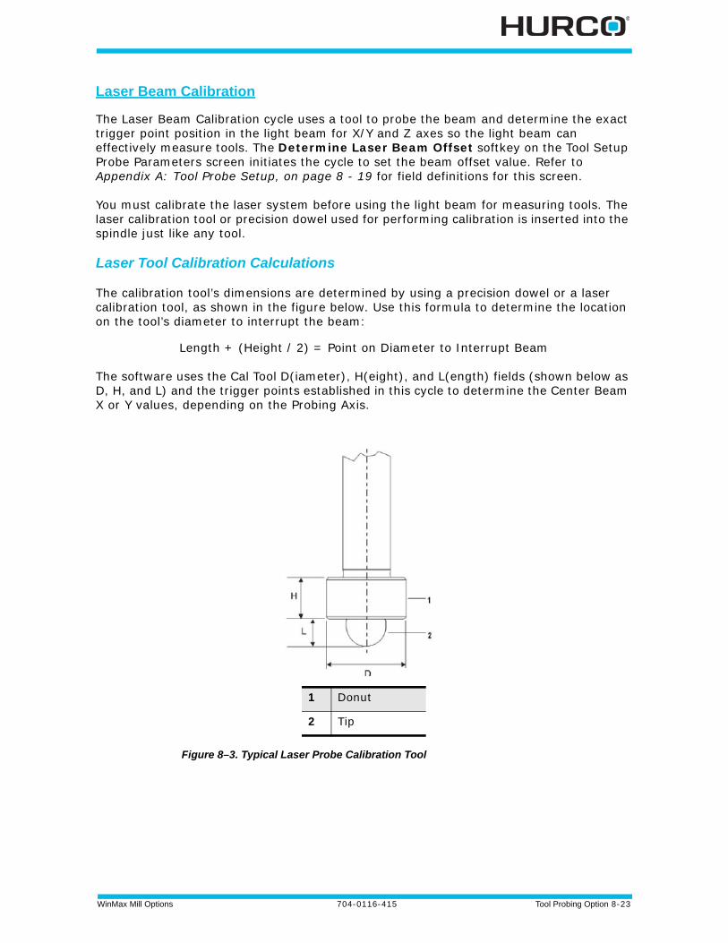
WinMax Mill Options 704-0116-415 Tool Probing Option 8-23
Laser Beam Calibration
The Laser Beam Calibration cycle uses a tool to probe the beam and determine the exact trigger point position in the light beam for X/Y and Z axes so the light beam can effectively measure tools. The Determine Laser Beam Offset softkey on the Tool Setup Probe Parameters screen initiates the cycle to set the beam offset value. Refer to Appendix A: Tool Probe Setup, on page 8 - 19 for field definitions for this screen.
You must calibrate the laser system before using the light beam for measuring tools. The laser calibration tool or precision dowel used for performing calibration is inserted into the spindle just like any tool.
Laser Tool Calibration Calculations
The calibration tool’s dimensions are determined by using a precision dowel or a laser calibration tool, as shown in the figure below. Use this formula to determine the location on the tool’s diameter to interrupt the beam:
Length + (Height / 2) = Point on Diameter to Interrupt Beam
The software uses the Cal Tool D(iameter), H(eight), and L(ength) fields (shown below as D, H, and L) and the trigger points established in this cycle to determine the Center Beam X or Y values, depending on the Probing Axis.
Figure 8–3. Typical Laser Probe Calibration Tool
1 Donut
2 Tip
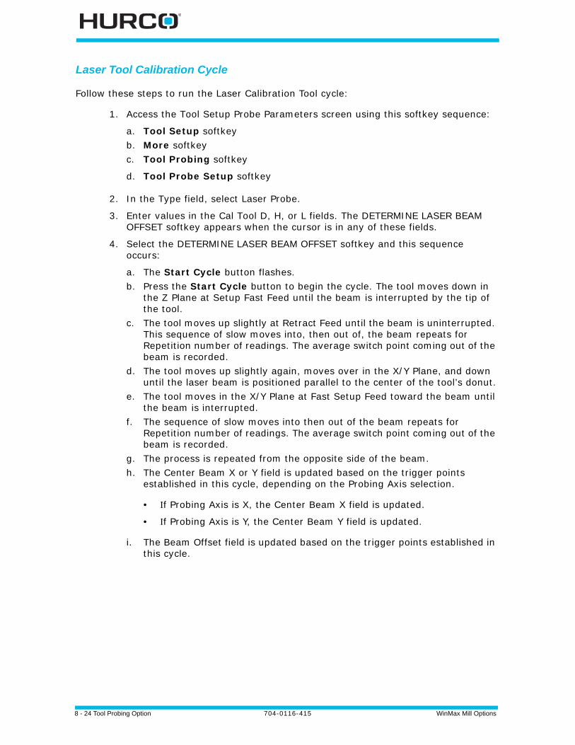
8 - 24 Tool Probing Option 704-0116-415 WinMax Mill Options
Laser Tool Calibration Cycle
Follow these steps to run the Laser Calibration Tool cycle:
1. Access the Tool Setup Probe Parameters screen using this softkey sequence:
a. Tool Setup softkeyb. More softkeyc. Tool Probing softkey
d. Tool Probe Setup softkey
2. In the Type field, select Laser Probe.
3. Enter values in the Cal Tool D, H, or L fields. The DETERMINE LASER BEAM OFFSET softkey appears when the cursor is in any of these fields.
4. Select the DETERMINE LASER BEAM OFFSET softkey and this sequence occurs:
a. The Start Cycle button flashes.b. Press the Start Cycle button to begin the cycle. The tool moves down in
the Z Plane at Setup Fast Feed until the beam is interrupted by the tip of the tool.
c. The tool moves up slightly at Retract Feed until the beam is uninterrupted. This sequence of slow moves into, then out of, the beam repeats for Repetition number of readings. The average switch point coming out of the beam is recorded.
d. The tool moves up slightly again, moves over in the X/Y Plane, and down until the laser beam is positioned parallel to the center of the tool’s donut.
e. The tool moves in the X/Y Plane at Fast Setup Feed toward the beam until the beam is interrupted.
f. The sequence of slow moves into then out of the beam repeats for Repetition number of readings. The average switch point coming out of the beam is recorded.
g. The process is repeated from the opposite side of the beam.h. The Center Beam X or Y field is updated based on the trigger points
established in this cycle, depending on the Probing Axis selection.
• f Probing Axis is X, the Center Beam X field is updated.
• f Probing Axis is Y, the Center Beam Y field is updated.
i. The Beam Offset field is updated based on the trigger points established in this cycle.
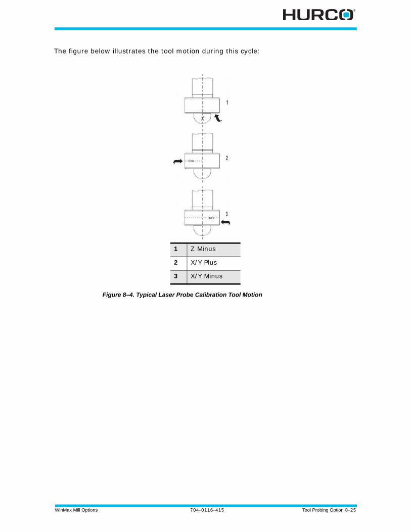
WinMax Mill Options 704-0116-415 Tool Probing Option 8-25
The figure below illustrates the tool motion during this cycle:
Figure 8–4. Typical Laser Probe Calibration Tool Motion
1 Z Minus
2 X/Y Plus
3 X/Y Minus

8 - 26 Tool Probing Option 704-0116-415 WinMax Mill Options
Probe Deflection Offset Calibration
Tool and part probe deflection offsets are the difference between the contact point of the probe and the actual receipt of a probe deflection signal. The offsets may vary for each direction of deflection. The switch points are repeatable to one micron or less.
These offsets need to be adjusted during an initial probe installation, a new stylus installation, or for centering or re-centering a stylus. They do not need to be performed each time the control is reset.
Tool Probe Deflection Offset
Access the Tool Probe Deflection Offset screen from the Tool Setup screen. Select the Tool Probing softkey, the Tool Probe Setup softkey, and the Tool Probe Deflection Offset softkey. This screen appears:
Figure 8–5. Tool Probe Deflection Offsets
The Reference Tool Diameter field holds the diameter of the tool being probed.
The probe orientation determines the offsets used in the Probe Stylus Position fields. The -Z offset is always used along with +/-X or +/-Y, depending from which direction the probe can deflect.
The following sections describe the two methods for determining Tool Probe Deflection Offsets: Absolute Location, on page 8 - 27 or Reference Tool Touch, on page 8 - 27.

WinMax Mill Options 704-0116-415 Tool Probing Option 8-27
Absolute Location
Use an edge finder to determine the absolute location of each edge of the probe stylus.
1. Enter the Reference Tool Diameter.
2. Position the cursor on the desired offset field.
3. Position the reference tool to the correct start position.
4. Press the Use Probe To Determine Offset softkey. The Start Button flashes.
5. Press the flashing Start Button.
a. The cursor position determines which axis is moved and in what direction.b. The deflected position is used to calculate the offsets.c. The offset value appears in the current field.d. The offsets are saved by the system so they are retained after power to the
machine is turned off.e. Unused fields contain a 0 value.f. The sign of the offset is + for plus axis deflections and - for negative axis
deflections.
Reference Tool Touch
Use a feeler gauge to determine the position where the reference tool touches the top and each side of the probe stylus. Follow the prompts on the screen to know which side of the stylus to use. Follow these steps:
1. Enter a 0 for the Reference Tool Diameter.
2. Position the reference tool in the correct start position. Begin with the top of the stylus.
3. Place the cursor in the -Z field of the Probe Stylus column.
4. Press the USE PROBE TO DETERMINE OFFSET (F1) softkey. The Start Button flashes.
5. Press the flashing Start Button.
a. The cursor position determines which axis is moved and in what direction.b. The deflected position is used to calculate the offsets.c. The offset value appears in the -Z field.d. The offsets are saved by the system so they are retained after power to the
machine is turned off.e. Unused fields contain a 0 value.f. The sign of the offset is + for plus axis deflections and - for negative axis
deflections.
6. Repeat these steps for the other two axis positions (+/- X and +/-Y). Position the reference tool appropriately and put the cursor in the appropriate
The Apply G Code Offset parameter applies the deflection offsets to G31 commands when conversational and NC probing are used together.

8 - 28 Tool Probing Option 704-0116-415 WinMax Mill Options
Probe Stylus field.
You can manually adjust the deflection offsets to optimize performance. By running a probe cycle on a reference tool you may make slight adjustments to the deflection offsets until the cycle returns with the exact value(s) desired.
The Apply G Code Offset parameter applies the deflection offsets to G31 commands when conversational and NC probing are used together.

WinMax Mill Options 704-0116-415 Tool Probing Option 8-29
Appendix B: Tool Probe Calibration
The Tool Probe must be calibrated before probing can be performed.
Probe Calibration—Absolute Tool Length mode
To calibrate the Tool Probe:
1. Access the Tool Measurement screen (Tool Setup/More/Tool Measurement Settings softkey):
2. Specify Probe in the Device field.
The Z Reference position must be known to proceed. Z Reference is the distance from the table top to Machine Zero. If already set, skip to step 8.
3. Advance to Z Reference field.
4. Place a gauge of known height on table top.
5. With a reference tool in spindle, jog Z-axis down and carefully touch reference tool to top of gauge block.
6. Select the Store Machine Position softkey or press the store position button on remote jog unit.
7. Subtract the reference tool length and the gauge height from the stored machine position, and manually enter this value in the Z Reference field.
For example, if the stored machine position is -300mm, and the reference tool length = 150mm, and the gauge height = 50mm, the Z Reference value is -500mm.
8. Access the Tool Setup screen. Enter the exact tool length for the Reference Tool in the Tool Cal Length field.
9. Select the More softkey, and then the Tool Probing softkey. The Tool Probing screen opens.
10.Select Length in the Cycle field.
11.Select the Calibrate the Tool Probe softkey. The control asks for the reference tool (number) to use for calibrating the probe; enter the number and select OK to calibrate the probe.
12.When calibration is complete, the Tool Measurement screen opens and the Height and Z Location fields contain the measured and calculated values:
Probe Calibration must be completed before probing can begin, but they only need to be done one time, unless the probe is relocated or replaced, if the Slow Feed value is changed, or if the tool calibration mode is changed.
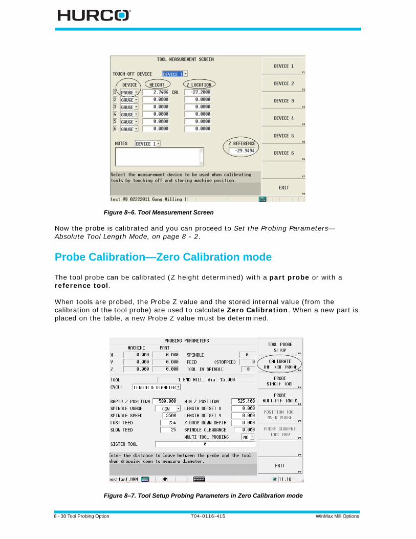
8 - 30 Tool Probing Option 704-0116-415 WinMax Mill Options
Figure 8–6. Tool Measurement Screen
Now the probe is calibrated and you can proceed to Set the Probing Parameters—Absolute Tool Length Mode, on page 8 - 2.
Probe Calibration—Zero Calibration mode
The tool probe can be calibrated (Z height determined) with a part probe or with a reference tool.
When tools are probed, the Probe Z value and the stored internal value (from the calibration of the tool probe) are used to calculate Zero Calibration. When a new part is placed on the table, a new Probe Z value must be determined.
Figure 8–7. Tool Setup Probing Parameters in Zero Calibration mode
WinMax Mill Options 704-0116-415 Tool Probing Option 8-31
Calibrate Tool Probe with Part Probe
The Tool Probe can be calibrated (Z height determined) with a Part Probe.
With the part probe in the spindle:
1. From the Tool Setup screen, select the More softkey.
2. Select the Tool Probing Softkey.
3. Set the Rapid Z Position. Use the remote jog unit to jog the part probe to a point just above the contact point of the tool probe and select the Set Position softkey, or type in a value for the Rapid Z Position field. (With the cursor in this field, the Position Tool Over Probe softkey can be used to position the part probe over the tool probe before jogging Z to the desired position.)
4. Select the Calibrate the Tool Probe softkey.
5. Press the flashing Start Cycle button.
The control activates the part probe and the Z axis moves down at rapid, then at Approach Feed until a probe deflection occurs or Minimum Z is reached. (f the probe reaches Minimum Z prior to deflection, an error message appears. Minimum Z is set in the Part Setup Probe Parameters.)
If the appropriate fields are set correctly, then the two probes will touch (or the part probe breaks the beam on a laser tool probe). The part probe will then retract slightly and touch again at the feed rate specified in the Measurement Feed field. The average deflection position is recorded and saved internally for the Zero Calibration value calculation.
Next you must determine the Probe Z value. See Determine Probe Z, on page 8 - 9.
Calibrate Tool Probe with Reference Tool
The Tool Probe can be calibrated (Z height determined) with a Reference Tool.
1. From the Tool Setup screen, select the More softkey.
2. Select the Tool Probing Softkey.
3. Set the Rapid Z Position. Use the remote jog unit to jog the reference tool to a point just above the contact point of the tool probe and select the Set Position softkey, or type in a value for the Rapid Z Position field. (With the cursor in this field, the Position Tool Over Probe softkey can be used to position the reference tool over the tool probe before jogging Z to the desired position.)
4. Select the Calibrate the Tool Probe softkey.
5. A prompt appears requesting the Reference Tool number. Enter the appropriate tool number and select OK.
When using a part probe, Part Probe Parameters and Deflection Offsets must be set before proceeding with tool probe calibration. Part Setup—Part Probe Parameters, on page 7 - 2 and Part Probe Deflection Offset Calibration, on page 7 - 3.

8 - 32 Tool Probing Option 704-0116-415 WinMax Mill Options
6. Press the flashing Start Cycle button.
The Z axis moves downward at rapid then at Fast Feed until a probe deflection occurs or Minimum Z is reached. (f the probe reaches Minimum Z prior to deflection, an error message appears. Minimum Z is set in the Tool Probing screen.)
The reference tool touches the tool probe, retracts slightly, and touches again at the feedrate specified in the Slow Feed field. The number of slow touches is specified by the Repetitions parameter. The average deflection position is recorded and saved internally for the Zero Calibration calculation.
Next you must determine the Probe Z value. See Determine Probe Z, on page 8 - 9.
If necessary, a tool change occurs, placing the reference tool in the spindle. If the tool is not in the magazine, the software will prompt you for the tool.

WinMax Mill Options 704-0116-415 Tool Probing Option 8-33
Appendix C: Probing Parameter Definitions
Tool Probing Parameter Definitions
Definitions for the fields on the Tool Probing screen are:
• Rapid Clearance (Absolute Tool Length only)—the distance above the probe stylus or beam that determines Rapid Z Position (based on approximate tool length and probe height in Z calibration).
• Rapid Z Position —the tool (in the Z axis) rapids down to this position and then continues downward at the speed specified in the Fast Feed field. For Zero Calibration mode, use the remote jog unit or type in a value for the Rapid Z Position field; For Absolute Tool Length mode the value is determined by Rapid Clearance.
With the cursor in this field, the Position Tool Over Probe softkey can be used to position the tool over the probe before jogging Z to the desired position.
• Spindle Usage—specifies the direction the spindle should turn during the probe cycle. Choices are: manual (free rotating), oriented, clockwise (CW) or counter clockwise (CCW).
• Spindle Speed—specifies spindle speed when the Spindle Usage field is set to either CW or CCW. When the operator sets the diameter setting for the tool probe, the Spindle RPM field will be set to a suggested value – this value may be overwritten by the operator. The suggested value for RPM is only done when the tool is first entered.
• Fast Feed—specifies the feed rate used when making the initial touch of the probe (prior to measurement touches). When the operator sets the diameter setting for the tool only the first time the tool is entered, the Fast Feed field will be updated with a suggested value—you may overwrite this value.
• Slow Feed—specifies the feed rate used when taking measurements after the initial deflection. The default value is 4 mm per minute for a touch probe, 25.4 mm per minute for a laser probe.
• Tool Cal Length (Absolute Tool Length only)—the Tool Cal Length value entered in Tool Setup.
• Min Length Delta (Absolute Tool Length only)—the distance below probe stylus or beam that the Z axis is allowed to travel; determines Min Z Position.
• Min Z Position—specifies that lowest position that Z will be allowed to travel during the probe cycle. This parameter sets up a safety zone for each tool. This value must be low enough to allow proper deflection of the probe. This is especially important when checking diameter as the tool must drop down next to the probe stylus.
• Length Offset X—used to change the X table position when probing – applies only when probing tool length. Required for tools that have a cutter offset from the center.
The default value for a touch tool probe is the reverse of the programmed tool. For example, if the tool is CW, Spindle Usage for a touch tool probe will default to CCW. For a laser tool probe, Spindle Usage value defaults to the programmed tool direction.
8 - 34 Tool Probing Option 704-0116-415 WinMax Mill Options
• Length Offset Y—used to change the Y table position when probing – applies only when probing tool length. Required for tools that have a cutter offset from the center.
• Z Drop Down Depth—used only when measuring tool diameter. This parameter (a negative value) indicates the distance to drop down from the surface of the probe or beam. For example, if you wish to measure the diameter of the tool ¼" from the tip, this parameter would be set to –0.25".
• Spindle Clearance—used only when measuring tool diameter. Specifies an additional distance to leave between the tool and tool probe when determining the tool diameter. This value can be adjusted to optimize probe cycle time.
• Multi-Tool Probing—specifies if multiple tools are to be probed. Yes will include current tool in multi-tool probe cycle.
• Sister Tool—specifies the spare tool for tool quality monitoring. See Tool Quality Monitoring, on page 8 - 14
Definitions for the softkeys on the Tool Probing screen are:
• Tool Probe Setup—opens the Tool Probe Parameters screen for probe setup.
• Calibrate the Tool Probe—determine the Z location of the tool probe. This value is retained on power down.
• Probe Single Tool—determine the length and/or diameter of a single tool.
• Probe Multiple Tools—determine the length and/or diameter of multiple tools.
• Position Tool Over Probe—move the tool into position over the probe.
• Probe Current Tool Now—determine the length and/or diameter of the current tool in spindle.
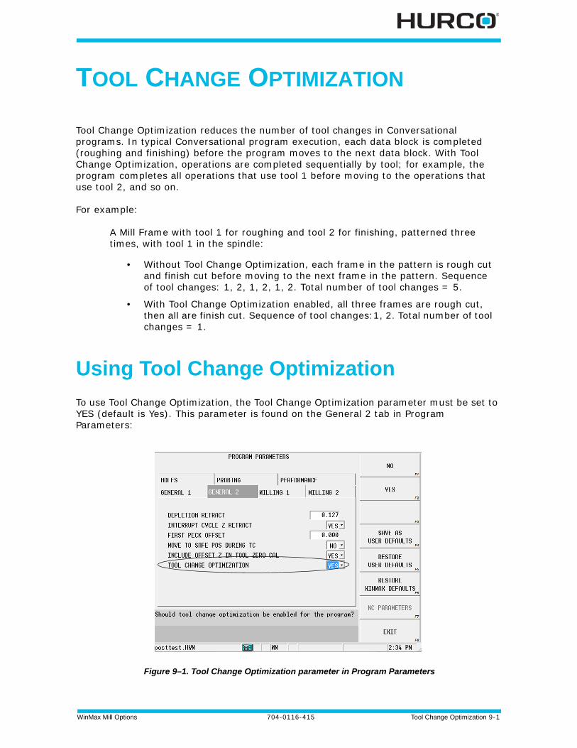
WinMax Mill Options 704-0116-415 Tool Change Optimization 9-1
TOOL CHANGE OPTIMIZATION
Tool Change Optimization reduces the number of tool changes in Conversational programs. In typical Conversational program execution, each data block is completed (roughing and finishing) before the program moves to the next data block. With Tool Change Optimization, operations are completed sequentially by tool; for example, the program completes all operations that use tool 1 before moving to the operations that use tool 2, and so on.
For example:
A Mill Frame with tool 1 for roughing and tool 2 for finishing, patterned three times, with tool 1 in the spindle:
• Without Tool Change Optimization, each frame in the pattern is rough cut and finish cut before moving to the next frame in the pattern. Sequence of tool changes: 1, 2, 1, 2, 1, 2. Total number of tool changes = 5.
• With Tool Change Optimization enabled, all three frames are rough cut, then all are finish cut. Sequence of tool changes:1, 2. Total number of tool changes = 1.
Using Tool Change Optimization
To use Tool Change Optimization, the Tool Change Optimization parameter must be set to YES (default is Yes). This parameter is found on the General 2 tab in Program Parameters:
Figure 9–1. Tool Change Optimization parameter in Program Parameters
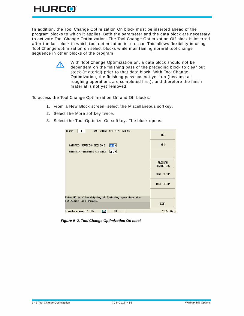
9 - 2 Tool Change Optimization 704-0116-415 WinMax Mill Options
In addition, the Tool Change Optimization On block must be inserted ahead of the program blocks to which it applies. Both the parameter and the data block are necessary to activate Tool Change Optimization. The Tool Change Optimization Off block is inserted after the last block in which tool optimization is to occur. This allows flexibility in using Tool Change optimization on select blocks while maintaining normal tool change sequence in other blocks of the program.
To access the Tool Change Optimization On and Off blocks:
1. From a New Block screen, select the Miscellaneous softkey.
2. Select the More softkey twice.
3. Select the Tool Optimize On softkey. The block opens:
Figure 9–2. Tool Change Optimization On block
With Tool Change Optimization on, a data block should not be dependent on the finishing pass of the preceding block to clear out stock (material) prior to that data block. With Tool Change Optimization, the finishing pass has not yet run (because all roughing operations are completed first), and therefore the finish material is not yet removed.
WinMax Mill Options 704-0116-415 Tool Change Optimization 9-3
The Tool Change Optimization On block contains the following fields:
• Maintain Roughing Sequence—when set to Yes, all roughing operations are performed in block sequence, including any specified tool changes. When set to No, all roughing operations are performed in tool change sequence. Default is No.
• Maintain Finishing Sequence—when set to Yes, all finishing operations are performed in block sequence, including any specified tool changes. When set to No, all finishing operations are performed in tool change sequence. Default is No.
4. Select the Tool Optimize Off softkey. The Tool Change Optimization Off block is used to turn off the Tool Change Optimization feature for a block or group of blocks within a program, after the Tool Change Optimization On block has been used at an earlier point in the program.
For Holes, the first operation is treated as a roughing tool and will be executed when other roughing tools are executed, based on the maintain roughing sequence. The other hole operations will always follow the first hole operation. If the hole operation should not be started until a previous block has been finished, then be sure to disable Tool Change Optimization prior to hole operation.
The Maintain Finishing Sequence parameter does not apply to holes operations.
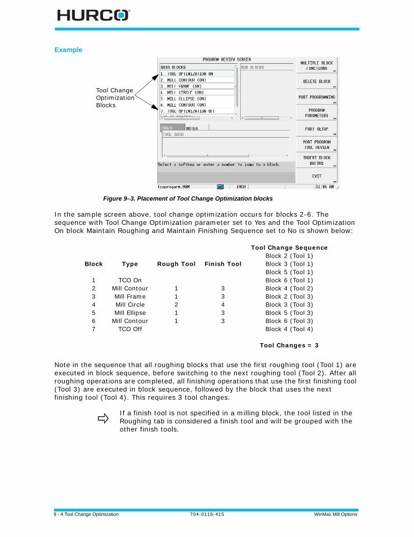
9 - 4 Tool Change Optimization 704-0116-415 WinMax Mill Options
Example
Figure 9–3. Placement of Tool Change Optimization blocks
In the sample screen above, tool change optimization occurs for blocks 2-6. The sequence with Tool Change Optimization parameter set to Yes and the Tool Optimization On block Maintain Roughing and Maintain Finishing Sequence set to No is shown below:
Note in the sequence that all roughing blocks that use the first roughing tool (Tool 1) are executed in block sequence, before switching to the next roughing tool (Tool 2). After all roughing operations are completed, all finishing operations that use the first finishing tool (Tool 3) are executed in block sequence, followed by the block that uses the next finishing tool (Tool 4). This requires 3 tool changes.
Block
1234567
Type
TCO OnMill ContourMill FrameMill CircleMill Ellipse
Mill ContourTCO Off
Rough Tool
11211
Finish Tool
33433
Tool Change SequenceBlock 2 (Tool 1)Block 3 (Tool 1)Block 5 (Tool 1)Block 6 (Tool 1)Block 4 (Tool 2)Block 2 (Tool 3)Block 3 (Tool 3)Block 5 (Tool 3)Block 6 (Tool 3)Block 4 (Tool 4)
Tool Changes = 3
If a finish tool is not specified in a milling block, the tool listed in the Roughing tab is considered a finish tool and will be grouped with the other finish tools.
Tool ChangeOptimizationBlocks
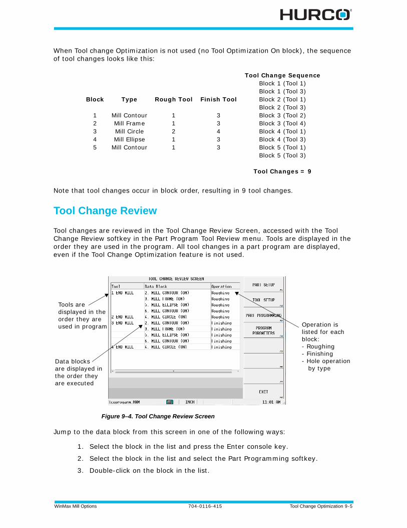
WinMax Mill Options 704-0116-415 Tool Change Optimization 9-5
When Tool change Optimization is not used (no Tool Optimization On block), the sequence of tool changes looks like this:
Note that tool changes occur in block order, resulting in 9 tool changes.
Tool Change Review
Tool changes are reviewed in the Tool Change Review Screen, accessed with the Tool Change Review softkey in the Part Program Tool Review menu. Tools are displayed in the order they are used in the program. All tool changes in a part program are displayed, even if the Tool Change Optimization feature is not used.
Figure 9–4. Tool Change Review Screen
Jump to the data block from this screen in one of the following ways:
1. Select the block in the list and press the Enter console key.
2. Select the block in the list and select the Part Programming softkey.
3. Double-click on the block in the list.
Block
12345
Type
Mill ContourMill FrameMill CircleMill Ellipse
Mill Contour
Rough Tool
11211
Finish Tool
33433
Tool Change SequenceBlock 1 (Tool 1)Block 1 (Tool 3)Block 2 (Tool 1)Block 2 (Tool 3)Block 3 (Tool 2)Block 3 (Tool 4)Block 4 (Tool 1)Block 4 (Tool 3)Block 5 (Tool 1)Block 5 (Tool 3)
Tool Changes = 9
Tools aredisplayed in theorder they areused in program
Data blocksare displayed inthe order they are executed
Operation islisted for eachblock:- Roughing- Finishing- Hole operation by type
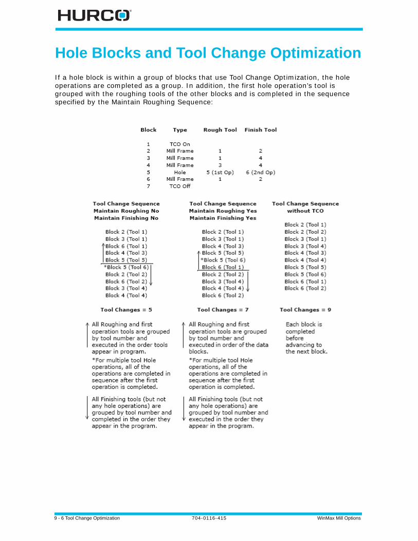
9 - 6 Tool Change Optimization 704-0116-415 WinMax Mill Options
Hole Blocks and Tool Change Optimization
If a hole block is within a group of blocks that use Tool Change Optimization, the hole operations are completed as a group. In addition, the first hole operation’s tool is grouped with the roughing tools of the other blocks and is completed in the sequence specified by the Maintain Roughing Sequence:
WinMax Mill Options 704-0116-415 Tool Fixture (TPS) Option 10-1
TOOL FIXTURE (TPS) OPTION
These topics are discussed in this section:
Tool Fixture Overview . . . . . . . . . . . . . . . . . . . . . . . . . . . . . . . . . . . . . . . 10 - 2
Automatic Tool Removal Using TPS. . . . . . . . . . . . . . . . . . . . . . . . . . . . . . 10 - 3
Automatic Tool Change Using TPS . . . . . . . . . . . . . . . . . . . . . . . . . . . . . . 10 - 4
Bypass TPS in an Automatic Tool Change . . . . . . . . . . . . . . . . . . . . . . . . . 10 - 5
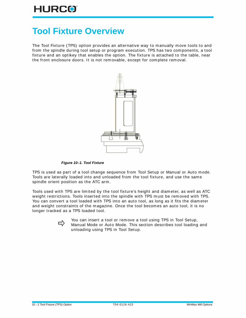
10 - 2 Tool Fixture (TPS) Option 704-0116-415 WinMax Mill Options
Tool Fixture Overview
The Tool Fixture (TPS) option provides an alternative way to manually move tools to and from the spindle during tool setup or program execution. TPS has two components, a tool fixture and an optikey that enables the option. The fixture is attached to the table, near the front enclosure doors. It is not removable, except for complete removal.
Figure 10–1. Tool Fixture
TPS is used as part of a tool change sequence from Tool Setup or Manual or Auto mode. Tools are laterally loaded into and unloaded from the tool fixture, and use the same spindle orient position as the ATC arm.
Tools used with TPS are limited by the tool fixture’s height and diameter, as well as ATC weight restrictions. Tools inserted into the spindle with TPS must be removed with TPS. You can convert a tool loaded with TPS into an auto tool, as long as it fits the diameter and weight constraints of the magazine. Once the tool becomes an auto tool, it is no longer tracked as a TPS loaded tool.
You can insert a tool or remove a tool using TPS in Tool Setup, Manual Mode or Auto Mode. This section describes tool loading and unloading using TPS in Tool Setup.
WinMax Mill Options 704-0116-415 Tool Fixture (TPS) Option 10-3
Automatic Tool Removal Using TPS
Follow the instructions below to use TPS to automatically remove a tool from the spindle:
1. Select the Input console key to access the Input screen.
2. Select the Tool Setup softkey.
3. With the cursor in the Tool field, enter the number of the tool you want to change into the spindle.
4. Select the Auto Tool Change console button. The Start Cycle button begins flashing.
5. Press the Start Cycle console button to initiate the tool removal process. The enclosure doors can now be opened. A "Confirm Empty Fixture. Close Doors and Press Start to Continue" message appears. The Start Cycle button flashes.
6. Make certain the Tool Fixture is empty. Press the Start Cycle button and its stops flashing.
7. A "Remove Tool X from Fixture, Close Doors & Press Start" message appears on the screen.
8. Remove the tool from the fixture, close the enclosure doors and Press the Start Cycle button.
9. The tool entered in step #3 is inserted from the magazine into the spindle.
10. The tool removal is complete. You must use Manual Mode if the tool you are removing was the last tool in the spindle.
10 - 4 Tool Fixture (TPS) Option 704-0116-415 WinMax Mill Options
Automatic Tool Change Using TPS
Follow the instructions below to complete an Auto Tool change using TPS
1. Select the Input console button to access the Input screen.
2. Select the Tool Setup softkey to access the Tool Setup screen.
3. With the cursor in the Tool field, enter the number of the tool that will be inserted into the spindle using TPS.
4. Press the Tool Changer Auto console button. The Start Cycle button begins flashing.
5. Press the Start Cycle button to initiate the tool change.
a. The Z axis rapids to the home position. b. The X and Y axes rapid to the Access position. An "Insert Tool X in Fixture.
Press Start" message appears. The Start Cycle button flashes again.
6. Insert the tool into the fixture.
7. Close the enclosure doors. Press the Start Cycle button.
a. The Start Cycle button stops flashing. b. The X and Y axes rapid to the Fixture position. c. The spindle orients (if it is not already oriented). d. The spindle unclamps. e. The Z axis rapids to the Clear position (its position before the tool change
began) - then moves at a fixed, reduced feedrate to the Fixture position. The spindle clamps the tool.
f. The Z-axis moves to the Fixture position at a reduced feedrate. g. The spindle clamps the tool. h. The X and Y axes move to the Clear position (their positions before the tool
change began) at a reduced feedrate. i. The Z axis rapids to the Tool Change position.
8. The tool change is complete.
If the Tool in Spindle is 0, a message will appear confirming that the spindle is empty. If the Tool in Spindle is a number other than 0, the tool will be removed from the spindle (automatically put into the magazine or you will be prompted to be removed manually)
A message requesting the tool be removed from the spindle using TPS will be displayed for any tool that was inserted into the spindle with TPS. You may use TPS to remove the tool or manually unclamp the tool to remove it from the spindle.
WinMax Mill Options 704-0116-415 Tool Fixture (TPS) Option 10-5
Bypass TPS in an Automatic Tool Change
Follow the instructions below to complete an Auto Tool change and bypass TPS:
1. Select the Input console button to access the Input screen.
2. Select the Tool Setup softkey to access the Tool Setup screen.
3. With the cursor in the Tool field, enter the number of the tool that will be inserted into the spindle.
4. Press the Tool Changer Auto console button; the Start Cycle button begins flashing. Press the Start Cycle button. If there is a tool in the spindle, remove it before proceeding. If the spindle is empty, the machine moves to the Access position.
5. When prompted to insert the tool into the fixture, manually insert the tool into the spindle. To install a tool using TPS, see Automatic Tool Removal Using TPS, on page 10 - 3.
a. Press the spindle unclamp button and insert the tool. The prompt changes to "Insert Tool XX in Spindle & Press Start Cycle."
b. Release the unclamp button. The tool is clamped in the spindle.
6. Close the enclosure doors and press the Start Cycle button.
7. The tool change is complete. Any tool that is inserted into the spindle manually (bypassing TPS) must be removed manually.

10 - 6 Tool Fixture (TPS) Option 704-0116-415 WinMax Mill Options
WinMax Mill Options 704-0116-415 UltiMotion 11-1
ULTIMOTION
Hurco’s UltiMotion system provides the following benefits:
Improved Surface Quality
With Hurco's proprietary smoothing, lookahead and motion control technology, the UltiMotion system provides significantly improved part surface quality. You'll see smoother and shinier surfaces, less vibration, less chatter marks, and higher accuracy.
Higher Throughput
Compared with a standard motion system, the UltiMotion system's advanced motion planning and rapid corner feature can provide decreased cycle time with the same or even better surface finish quality. This is especially true for parts with complex geometries or large amounts of repeated tasks, such as drilling or tapping.
Rapid Corner
For programs with a lot of consecutive rapid moves, the UltiMotion system doesn't stop between two rapids. Instead, it travels through blended corners at very high speed with only negligible deviation. This saves significant amount of time for repeated tasks, such as drilling and tapping.
Broader Performance Range for Surface Finish Quality
The Surface Finish Quality (SFQ) mechanism is Hurco's proprietary technology to allow users to choose better surface finish or higher throughput for their applications via a simple one-parameter control mechanism. Winmax control automatically adjusts internal parameters to achieve either better surface quality (smaller SFQ) or higher throughput (higher SFQ). The UltiMotion system extends the performance range for SFQ to have even better surface quality for your finish pass and even more time savings in the roughing or semi-roughing passes.
Higher Quality Rigid and Regular Tapping
The UltiMotion system deploys a coordinated motion control mechanism for regular and rigid tapping. You no longer need to worry if your tap will pass go/no-go tests; the UltiMotion system monitors the spindle angle at all times and controls the Z-axis to track the spindle position.
Smoother Motion Results in Longer Machine Life
Rough motion, vibration, and bumping increase mechanical system fatigue and shorten machine life. The UltiMotion system's unique acceleration and jerk control, along with its advanced motion planning, have made it possible to achieve faster, yet smoother motion. You will get a faster machine with extended machine life.
11 - 2 UltiMotion 704-0116-415 WinMax Mill Options
Robust and Consistent Performance Over a Wide Range of Working Conditions
Have you ever had trouble maintaining the equivalent performance with work pieces weighing from several ounces to several thousands of pounds? The UltiMotion system's advance and accurate model compensation will help you to maintain the same level of performance over a wide range of working conditions.
Dynamic Variable Lookahead Algorithm
Hurco's proprietary Lookahead doesn't require a fixed number of blocks lookahead like conventional controls; instead the lookahead varies dynamically depending on the geometry and motion profile, but always guarantees there is enough to make optimized maneuvers.
Smooth and Responsive Handwheel Jogging
Compared with standard system, the UltiMotion system's hand wheel jogging is optimized to reduce bumping and vibration while providing more responsiveness.
How to Select the Motion System
The UltiMotion option must be installed. To turn it on or off:
1. Select the Auxiliary console button.
2. Select the Utility Screen softkey.
3. Select the System Configuration softkey.
4. Select the WinMax Configuration softkey.
5. Select the Motion Configuration softkey. The Motion Configuration screen opens and the current motion system is displayed.
6. Select either Standard or UltiMotion in the Motion System field. The system must be restarted for the change to take effect.
WinMax Mill Options 704-0116-415 UltiMonitor 12-1
ULTIMONITOR
The UltiMonitor option adds capability and flexibility to your WinMax Mill operation by providing connection to your Local Area Network (LAN). Using UltiMonitor, you can communicate with other CNCs, and with PCs or file servers connected to your LAN using standard TCP/IP and FTP protocols. UltiMonitor also includes Extended Shop Floor (ESF) for remote machine monitoring and communication.
This section covers the use of the UltiMonitor product. For information about basic system operation, refer to the Getting Started with WinMax Mill manual.
LAN Requirements . . . . . . . . . . . . . . . . . . . . . . . . . . . . . . . . . . . . . . . . . 12 - 2
Configuring a Network. . . . . . . . . . . . . . . . . . . . . . . . . . . . . . . . . . . . . . . 12 - 4
Using FTP . . . . . . . . . . . . . . . . . . . . . . . . . . . . . . . . . . . . . . . . . . . . . . . 12 - 9
Extended Shop Floor (ESF) . . . . . . . . . . . . . . . . . . . . . . . . . . . . . . . . . . . 12 - 13
Customers using UltiNet should refer to this section for product guidance. The UltiNet option provides the same FTP connectivity as UltiMonitor but does not include ESF.
12 - 2 UltiMonitor 704-0116-415 WinMax Mill Options
LAN Requirements
To use UltiMonitor, you must have a Local Area Network (LAN or “network”) that supports the IEEE 802.3 Ethernet hardware standards. Contact your IT provider for guidance about proper LAN design and setup.
Limitations for UltiMonitor
1. Do NOT connect machines to a domain. When connecting a machine to a network, a workgroup must be used. WinMax software runs on an embedded Windows operating system, and any changes to the system could cause unwanted effects.
2. Installing any physical cards, including wireless devices, is NOT supported. WinMax is designed and configured to operate with the existing system hardware.
3. Use of an Ethernet cable connection to a machine is required.
Glossary of Networking Terms
Following are definitions for networking terms used throughout this section.
• Client/Server—This is a term commonly used to describe how computers do work for each other. One computer runs server software; the other computer runs client software. The server software waits for requests from the client in order to perform tasks. Many times the server is a background task that runs all the time. A client is a user application on a PC or some other workstation and usually will not run all the time. A user may begin running client software, do some work, then shut down the client when finished. It is important to note that a single server may handle many clients. It is also possible for a computer to function as both a client and a server simultaneously.
• Ethernet—Ethernet is a particular networking technology specification. Ethernet uses CSMA/CD to gain access to the network media (cable). CSMA/CD stands for Carrier Sense Multiple Access with Collision Detection. Ethernet sends its data on a carrier wave. Since there are multiple Ethernet adapters attached to the same cable, they must take turns sending data. When ready to transmit, an adapter checks for the presence of a carrier wave. If no carrier is detected, the adapter begins transmission. If another adapter begins transmitting data at the same time, a collision will occur. The Ethernet hardware senses when a collision occurs. The two adapters involved in the collision will stop, delay for a random length of time, and then try to retransmit the data. This process repeats until the data is successfully sent. Data is sent in the form of packets, which have a limited size, allowing other hosts an opportunity to use the network media.
• FTP—This is an acronym for File Transfer Protocol. FTP is implemented using the client/server model and uses TCP/IP as its protocols. FTP software contains a standard set of commands that are used to transfer files and manage directory structures.
• Host—Any computer connected to a network can be a host, including a PC running DOS, Windows XP/Vista/7, Windows NT; a UNIX workstation; a

WinMax Mill Options 704-0116-415 UltiMonitor 12-3
mainframe computer; a CNC control; or any machine with networking capability.
• IP Address—An IP (Internet Protocol) address is used to identify a particular host on a network. Each host on a network must have a unique IP address consisting of a 32-bit number usually presented in dotted decimal format; for example, 200.100.150.1. This format divides the address into four single byte values separated by decimal points. On most networks, the first three bytes represent the network and the last byte is the host. Following this practice, the first three bytes are the same for all hosts and the last byte is different for each host. On the Internet, these cryptic addresses usually are not usedmost addresses are represented as plain text, which are converted to IP addresses by DNS, or Domain Name Server. The underlying protocol still uses the unique 32-bit IP addresses.
• TCP/IP—This is an acronym for the two major protocols of the Internet, Transmission Control Protocol and Internet Protocol. IP data normally reaches its intended destination, but there is no failure notification for the sender if it does not. TCP, however, has an acknowledgment that the message was received. The TCP layer of a protocol stack uses IP to send a message in the form of packets, or bundles of data. Each packet must be acknowledged or it will be sent again. This process repeats until the entire message, which contains multiple packets, is received. TCP is defined as a reliable stream-oriented protocol. The use of TCP/IP is not limited to the Internet. It is commonly used for communication between hosts on LANs (local area networks). It may be used for any application that requires reliable data transfer.
12 - 4 UltiMonitor 704-0116-415 WinMax Mill Options
Configuring a Network
UltiMonitor allows machines to be connected on a Local Area Network (LAN or “network”).
Configuring an IP address for your machine
An Internet Protocol (IP) address is a numerical label assigned to each device in a computer network. IP addresses are assigned to a host either at the time of booting, or permanently by fixed configuration of the hardware or software. Persistent configuration is also known as using a static IP address. In contrast, a dynamic IP address occurs when a device’s IP address is assigned with each reboot. All Hurco machines, by default, are configured to use dynamic IP addresses. This is shown in the figure below.
The configuration can be changed to a static IP address, if desired. IP addresses must always be unique to your network; contact your network administrator for the proper IP address values.
To access the LAN and Internet Protocol properties:
1. Select the Windows key (or the Ctrl+Esc keys) on the keyboard to access system settings through the Shell.
2. Expand the left pane of the Shell.
3. Select Control Panel.
4. Select Network Connections.
5. Enter password.
6. Highlight Local Area Connection.
7. Select File/Properties. (See Figure 12-1 a.)
8. Highlight Internet Protocol (TCP/IP).
9. Select Properties. The IP address configuration can be changed in the TCP/IP Properties box that opens. (See Figure 12-1 b.)

WinMax Mill Options 704-0116-415 UltiMonitor 12-5
Figure 12–1. Default LAN and Internet Protocol Properties
a. b.
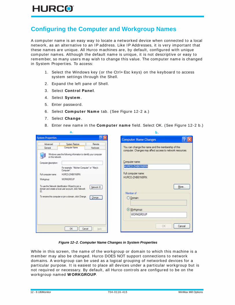
12 - 6 UltiMonitor 704-0116-415 WinMax Mill Options
Configuring the Computer and Workgroup Names
A computer name is an easy way to locate a networked device when connected to a local network, as an alternative to an IP address. Like IP Addresses, it is very important that these names are unique. All Hurco machines are, by default, configured with unique computer names. Although the default name is unique, it is not descriptive or easy to remember, so many users may wish to change this value. The computer name is changed in System Properties. To access:
1. Select the Windows key (or the Ctrl+Esc keys) on the keyboard to access system settings through the Shell.
2. Expand the left pane of Shell.
3. Select Control Panel.
4. Select System.
5. Enter password.
6. Select Computer Name tab. (See Figure 12-2 a.)
7. Select Change.
8. Enter new name in the Computer name field. Select OK. (See Figure 12-2 b.)
Figure 12–2. Computer Name Changes in System Properties
While in this screen, the name of the workgroup or domain to which this machine is a member may also be changed. Hurco DOES NOT support connections to network domains. A workgroup can be used as a logical grouping of networked devices for a particular purpose. It is easiest to place all devices under a particular workgroup but is not required or necessary. By default, all Hurco controls are configured to be on the workgroup named WORKGROUP.
a. b.

WinMax Mill Options 704-0116-415 UltiMonitor 12-7
Mapping a Network Drive
A server share is basically a folder on a different computer that is being shared with everyone else. So when you “map a drive,” you are saying that you want access to that folder on your computer also, which is done by mapping it to a letter, for example, F, G, H, etc. To access the Map Network Drive dialog:
1. Select the Windows key (or the Ctrl+Esc keys) on the keyboard to access system settings through the Shell.
2. Expand right pane of Shell.
3. Select Map Drive.
4. Enter password. The Map Network Drive dialog box opens:
Figure 12–3. Map Network Drive dialog
To map a network drive:
1. Select an unused Drive letter to represent the shared folder and type in the UNC path in the Folder field. UNC path is a special format for pointing to a folder on another computer. The format is \\computer name\folder name.
If you're not sure what the name of the folder is, you can select Browse... to find the computer that way. Select Entire Network, then Microsoft Windows Network and expand the workgroup that your computer is in.
2. Click Reconnect at logon to make the connection permanent, which means the drive will still be mapped even after you restart the computer.
If the drive is password protected, use the “Connect using a different user name” link in the mapping window to configure the mapping with the user name and password.

12 - 8 UltiMonitor 704-0116-415 WinMax Mill Options

WinMax Mill Options 704-0116-415 UltiMonitor 12-9
Using FTP
FTP (File Transfer Protocol) is a method of transferring files from one computer to another, using the Internet. For Hurco machining and turning centers, FTP is required for transferring programs between two or more machines. FTP can also be used to transfer programs between a computer and a machine.
FTP Server Settings
To access the FTP Server Settings screen:
1. Press the Auxiliary console key.
2. Select the Utilities softkey to access the Utilities screen and softkey menu.
3. Select the User Preferences softkey.
4. Select the More softkey.
5. Select the FTP Server Settings softkey. The screen is displayed:
Figure 12–4. FTP Server Settings screen
FTP Server Settings Fields
These fields are available on the FTP Server Settings screen:
• Enable FTP Server—select Yes to enable or No to disable the FTP server.
• FTP Server Port—enter a number for the FTP server port. The default is 21.
• Maximum Idle Time (mins)—enter the number of idle time minutes before the server disconnects. The default is 0 with no time out.
• User 1-4 Name—enter each user’s logon name. Up to 4 users can logon.
• User 1-4 Password—enter each user’s logon password. Up to 4 users can logon.
12 - 10 UltiMonitor 704-0116-415 WinMax Mill Options
• User 1-4 Path—enter each user’s root path. Up to 4 users can logon.
FTP Server Settings Softkeys
These softkeys are available on the FTP Server Settings screen:
• Display WinMax IP Address—displays the IP address list in a pop-up window. Select OK to close the window.
An IP (Internet Protocol) address is used to identify a particular host on a network. Each host on a network must have a unique IP address consisting of a 32-bit number usually presented in dotted decimal format; for example, 200.10.150.1. This format divides the address into four single byte values separated by decimal points.
On most networks, the first three bytes represent the network and the last byte is the host. Following this practice, the first three bytes are the same for all hosts and the last byte is different for each host.
On the Internet, these cryptic addresses usually are not used—most addresses are represented as plain text, which are converted to IP addresses by DNS, or Domain Name Server. The underlying protocol still uses the unique 32-bit IP addresses.
• Change FTP Root Drive—displays a pop-up window to browse for a folder. Select the appropriate root drive and select OK to close the window. Select Cancel to stop browsing without changing the root drive.
• Disconnect All Users—select Yes in the pop-up window to disconnect all current FTP users; select No to cancel the disconnect operation.
If the logon name is “anonymous,” the password is not required.
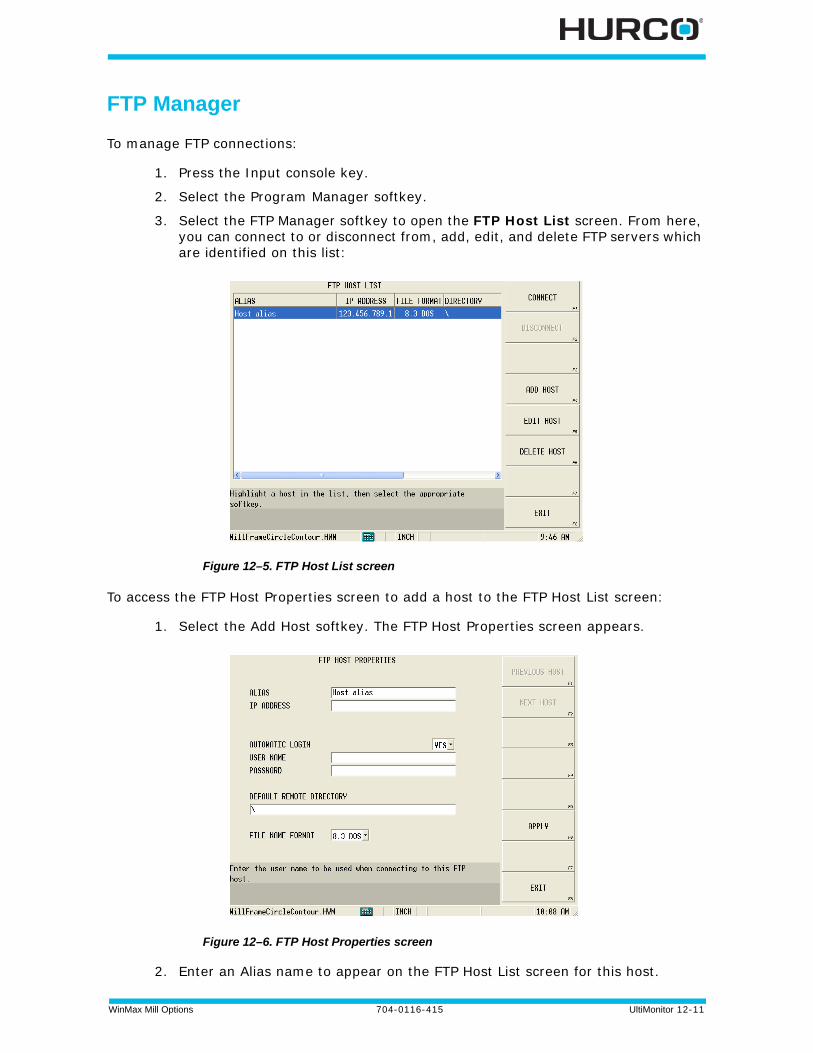
WinMax Mill Options 704-0116-415 UltiMonitor 12-11
FTP Manager
To manage FTP connections:
1. Press the Input console key.
2. Select the Program Manager softkey.
3. Select the FTP Manager softkey to open the FTP Host List screen. From here, you can connect to or disconnect from, add, edit, and delete FTP servers which are identified on this list:
Figure 12–5. FTP Host List screen
To access the FTP Host Properties screen to add a host to the FTP Host List screen:
1. Select the Add Host softkey. The FTP Host Properties screen appears.
Figure 12–6. FTP Host Properties screen
2. Enter an Alias name to appear on the FTP Host List screen for this host.
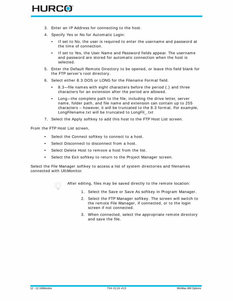
12 - 12 UltiMonitor 704-0116-415 WinMax Mill Options
3. Enter an IP Address for connecting to the host.
4. Specify Yes or No for Automatic Login:
• If set to No, the user is required to enter the username and password at the time of connection.
• If set to Yes, the User Name and Password fields appear. The username and password are stored for automatic connection when the host is selected.
5. Enter the Default Remote Directory to be opened, or leave this field blank for the FTP server’s root directory.
6. Select either 8.3 DOS or LONG for the Filename Format field.
• 8.3—file names with eight characters before the period (.) and three characters for an extension after the period are allowed.
• Long—the complete path to the file, including the drive letter, server name, folder path, and file name and extension can contain up to 255 characters – however, it will be truncated to the 8.3 format. For example, LongFilename.txt will be truncated to LongFil_.txt
7. Select the Apply softkey to add this host to the FTP Host List screen.
From the FTP Host List screen,
• Select the Connect softkey to connect to a host.
• Select Disconnect to disconnect from a host.
• Select Delete Host to remove a host from the list.
• Select the Exit softkey to return to the Project Manager screen.
Select the File Manager softkey to access a list of system directories and filenames connected with UltiMonitor.
After editing, files may be saved directly to the remote location:
1. Select the Save or Save As softkey in Program Manager.
2. Select the FTP Manager softkey. The screen will switch to the remote File Manager, if connected, or to the login screen if not connected.
3. When connected, select the appropriate remote directory and save the file.

WinMax Mill Options 704-0116-415 UltiMonitor 12-13
Extended Shop Floor (ESF)
Hurco’s Extended Shop Floor provides a web-based access point for a machine shop owner to communicate and view machine data using a web browser. Additionally, ESF is a distribution point for information about Hurco’s machine tools and it supports the remote monitoring and diagnosis of the machine. By default, an ESF connection is made to Hurco servers when an internet connection is present.
Here are the ESF connection states:
For more information refer to the ESF User’s Guide found at the ESF website, https://esf.hurco.com; a user account with password is required to access ESF.
ESF State Description
The ESF Machine Service is not running. Clicking this icon will turn the ESF Machine Service on.
Please wait while the ESF Machine Service is starting and attempting to establish a connection with the ESF Server.
The ESF Machine Service is running and communicating with the ESF Server. Clicking this icon will turn the ESF Machine Service off.
The ESF Machine Service is running but is unable to communicate with the ESF Server. There may be a problem with the network connection. Clicking this icon will turn the ESF Machine Service off.

12 - 14 UltiMonitor 704-0116-415 WinMax Mill Options
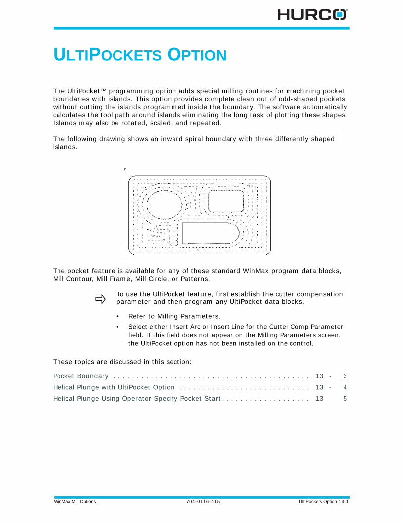
WinMax Mill Options 704-0116-415 UltiPockets Option 13-1
ULTIPOCKETS OPTION
The UltiPocket™ programming option adds special milling routines for machining pocket boundaries with islands. This option provides complete clean out of odd-shaped pockets without cutting the islands programmed inside the boundary. The software automatically calculates the tool path around islands eliminating the long task of plotting these shapes. Islands may also be rotated, scaled, and repeated.
The following drawing shows an inward spiral boundary with three differently shaped islands.
The pocket feature is available for any of these standard WinMax program data blocks, Mill Contour, Mill Frame, Mill Circle, or Patterns.
These topics are discussed in this section:
Pocket Boundary . . . . . . . . . . . . . . . . . . . . . . . . . . . . . . . . . . . . . . . . . . 13 - 2
Helical Plunge with UltiPocket Option . . . . . . . . . . . . . . . . . . . . . . . . . . . . 13 - 4
Helical Plunge Using Operator Specify Pocket Start . . . . . . . . . . . . . . . . . . . 13 - 5
To use the UltiPocket feature, first establish the cutter compensation parameter and then program any UltiPocket data blocks.
• Refer to Milling Parameters. • Select either Insert Arc or Insert Line for the Cutter Comp Parameter
field. If this field does not appear on the Milling Parameters screen, the UltiPocket option has not been installed on the control.

13 - 2 UltiPockets Option 704-0116-415 WinMax Mill Options
Pocket Boundary
The Pocket Boundary is the outside frame of the part. The basic philosophy of the UltiPocket option is to program the boundary and then tell the system which pockets or islands to avoid within that boundary. This approach eliminates complex calculations and shortens the part programming process.
There are two types of Pocket Boundaries: Spiral Outward (no islands) and Spiral Inward.
Spiral Outward - No Islands
This selection is only for Circle and Frame data blocks without islands. When this routine is selected, the tool begins from the center region of the part outward to pocket the entire programmed boundary. This operation is, therefore, the same as the standard WinMax Pocket selection. With this selection the cutter overlap is controlled by the Pocket Overlap value on the Milling Parameters screen, not the Pocket Overlap field on the Mill Circle and Mill Frame screens.
Spiral Inward
This selection cuts in from the outside of the defined boundary avoiding the defined islands. When this routine is selected, the tool enters the part and begins following a path formed by offsetting the boundary one-half the tool radius, plus the pocket overlap.
To control the percentage of overlap during cutting, enter a value in the Pocket Overlap field on the Mill Circle or Mill Frame screen. After the first pass, the tool follows a path produced by offsetting the boundary by the tool radius, plus the pocket overlap for each pass while avoiding islands inside the boundary.
After pocketing the boundary, the tool then cuts around the inside of the boundary and the outside of each island, using the selected blend offset and the programmed tool radius.
Programming Islands
After programming the mill data block for a boundary, an island can be defined by creating a Pocket Island data block. As many islands as desired may be defined (subject to computer memory on the control), but all must fit within the defined boundary and should allow the tool to completely define the island.
The island data block can be a Mill Frame, Circle, or Contour (provided it is a closed contour). The Pocket Island data blocks use the standard milling values from the boundary data block and do not display these parameters on the island programming screen. The pocket overlap percentage was also defined in the boundary data block.
Mill Contours

WinMax Mill Options 704-0116-415 UltiPockets Option 13-3
To create a Mill Contour data block using the UltiPocket option, set up the operation in the start segment (segment zero). As in standard WinMax milling, an UltiPocket Mill Contour block consists of segments beginning with segment zero. With the cursor in the MILLING TYPE field, select one of the Pocket options in the Start segment to indicate whether this block is the boundary of the part or one of the islands within the boundary. The boundary must occur first in the program.
The segments after the Start segment are programmed in the same manner as standard milling lines and arcs. Automatic calculation of unknown points is available for these data blocks.
Mill Frame
The Mill Frame data block is often used to create the part boundary.
This block is programmed in the same manner as the standard WinMax Mill Frame, with the addition of the Pocket Overlap percentage.
Mill Circle
The Mill Circle data block is used for both boundaries and islands. It is similar to the standard Mill Circle data block except that if this block is used to create an island, it uses the tool from the boundary data block.
Pattern
Pattern data blocks can be inserted to rotate, scale, or repeat islands. Only Pattern data blocks can be programmed between a boundary data block and an island. As many islands as desired may be defined (subject to available memory), but all must fit within the defined boundary.

13 - 4 UltiPockets Option 704-0116-415 WinMax Mill Options
Helical Plunge with UltiPocket Option
The Helical Plunge option is used with the UltiPocket option to define the plunging location when inward pocketing. Islands created using inward pocketing can influence plunge locations. A plunge location is determined that will not interfere with pocket islands.
The plunging location in outward pocketing is the same as a straight plunge. Outward pocketing is used only for mill frame, mill circle, and ellipse pocket boundaries that do not have pocket islands. Since islands are not present with outward pocketing, the plunging location is in the middle of the mill frame, mill circle and ellipse.
When the Helical Plunge option is installed, two additional pocketing-related fields appear on the Milling Parameters screen. These fields are Operator Specify Pocket Start and Inward Pocket Plunge Near Center.
The Operator Specify Pocket Start field takes precedence over the Inward Pocket Plunge Near Center field. If the Operator Specify Pocket Start field is set to Yes, the value of the Inward Pocket Plunge Near Center field is ignored.
When the Operator Specify Pocket Start field is set to No, the value of the Inward Pocket Plunge Near Center field is checked. If the Inward Pocket Plunge Near Center field is set to Yes, a starting location will be determined near the center of the pocket. If both fields are set to No, the default starting position will be used for the pocket.

WinMax Mill Options 704-0116-415 UltiPockets Option 13-5
Helical Plunge Using Operator Specify Pocket Start
To use the Operator Specify Pocket Start function:
1. Set the Type field to Pocket Boundary on the Mill Contour, Mill Frame or Mill Circle screen.
2. Set the Pocket Type field to Inward on the Mill Contour, Mill Frame or Mill Circle screen.
3. Set the Operator Specify Pocket Start field to Yes on the Milling Parameters screen.
4. The Pocket X Start and Pocket Y Start fields appear on the Mill Contour, Mill Frame, or Mill Circle screen. The operator identifies the pocket plunge location with the Pocket X Start and Pocket Y Start fields.
The Pocket X Start and Pocket Y Start fields define the centerline of the plunge path. This is the location where the helix will be centered. If a straight plunge is selected, the straight plunge will occur at the location.
The following figure shows the Pocket X Start and Pocket Y Start fields on the Mill Frame screen. See the "Helical Plunge Option" chapter for an example using Pocket Start X and Pocket Start Y fields.
For non-rotary blocks, Pocket X Start and Pocket Y Start define the XY starting location. For rotary blocks, these fields define the XA starting location.
An error message will display if the values for Pocket X Start or Pocket Y Start interfere with the pocket island or pocket boundary.

13 - 6 UltiPockets Option 704-0116-415 WinMax Mill Options

WinMax Mill Options 704-0116-415 Record of Changes — 1
RECORD OF CHANGES
04-0116-415 rB, Nov 2012
Revised by: H.Arle
Approved by: D.Skrzypczak, Nov 2012
04-0116-415 rA, Aug 2012
Revised by: H.Arle
Approved by: D.Skrzypczak, Aug 2012
04-0116-410 rL, July 2012
Revised by: H.Arle
Approved by: D.Skrzypczak, July 2012
04-0116-410 rK, June 2012
Revised by: H.Arle
Approved by: D.Skrzypczak, June 2012
Changes
• Updates to reflect software changes.
Changes
• Updates to reflect software changes, including:
• Tool Diameter or Diameter Wear stored with Tool Probing
Changes
• Updates to reflect software changes, including:
• several updates to Tool Probing, including new Tool Probe Cycle defaults screen.

- 2 Record of Changes 704-0116-415 Machine WinMax Mill Options
Changes
• Updates to reflect software changes.
Machine WinMax Mill Options 704-0116-415 Record of Changes -3
04-0116-410 rJ, December 2011
Revised by: H.Arle
Approved by: D.Skrzypczak, December 2011
04-0116-410 rI, October 2011
Revised by: H.Arle
Approved by: D.Skrzypczak, October 2011
04-0116-410 rH, August 2011
Revised by: H.Arle
Approved by: D.Skrzypczak, August 2011
704-0116-410 rG, June 2011
Revised by: H. Arle
Approved by: D. Skrzypczak, June 2011
Changes
• Updates to reflect software changes.
Changes
• Tool Probing chapter updates.
• Other updates to reflect software changes.
Changes
• Preliminary Tool Probing added.
• Other updates to reflect software changes.
Changes
• Updates to reflect software changes.
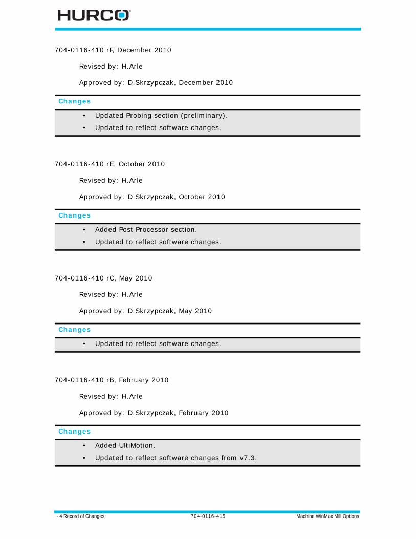
- 4 Record of Changes 704-0116-415 Machine WinMax Mill Options
704-0116-410 rF, December 2010
Revised by: H.Arle
Approved by: D.Skrzypczak, December 2010
704-0116-410 rE, October 2010
Revised by: H.Arle
Approved by: D.Skrzypczak, October 2010
704-0116-410 rC, May 2010
Revised by: H.Arle
Approved by: D.Skrzypczak, May 2010
704-0116-410 rB, February 2010
Revised by: H.Arle
Approved by: D.Skrzypczak, February 2010
Changes
• Updated Probing section (preliminary).
• Updated to reflect software changes.
Changes
• Added Post Processor section.
• Updated to reflect software changes.
Changes
• Updated to reflect software changes.
Changes
• Added UltiMotion.
• Updated to reflect software changes from v7.3.

Machine WinMax Mill Options 704-0116-415 Record of Changes -5
704-0116-410 rA, December 2009
Revised by: H.Arle
Approved by: D.Skrzypczak, Dec 2009
Changes
• Added Custom Drill.
• Added Mill Polygon.
• Added HD3 Serial Numbeing Lettering.
• Added Contour Arc content.
• Added Lettering Reference Locations content.
• Added Mill Slot.
• Added Thread Mill.
• Updated to reflect software changes from v7.3.

- 6 Record of Changes 704-0116-415 Machine WinMax Mill Options
WinMax Mill Options 704-0116-415 Index — 1
INDEX
Numerics3D Mold 1 - 1
Blend Arc 1 - 12Contour 1 - 9Line 1 - 10Parameters 1 - 2
AA Angle field
Rotary Lines and Arcs Start Segment 5 -14
Rotary Position block 5 - 11A Center field
Rotary Circle block 5 - 16Rotary Lines and Arcs Arc Segment 5 -
15Rotary Lines and Arcs Blend Arc
Segment 5 - 15A Corner field
Rotary Frame block 5 - 16A Distance field
Rotary Loop block 5 - 17, 5 - 23A End field
Rotary Lines and Arc Blend Arc Segment 5 - 15
Rotary Lines and Arcs Arc Segment 5 -15
Rotary Lines and Arcs Line Segment 5 -14
A Length fieldRotary Frame block 5 - 16
A Start fieldRotary Lines and Arcs Arc Segment 5 -
15Rotary Lines and Arcs Blend Arc
Segment 5 - 15Rotary Lines and Arcs Line Segment 5 -
14A-axis rotation 5 - 2absolute location, tool probing 8 - 27ACCEPT POSITION AS PART ZERO (F1)
softkeyCylinder cycle 7 - 16Edge cycle 7 - 29, 7 - 33Hole or Circle Pocket cycle 7 - 32Part Zero storage 7 - 15Plane Intersection cycle 7 - 19Rectangular Pocket cycle 7 - 25Rectangular Solid cycle 7 - 22
Accept softkey, DXF 2 - 3, 2 - 7ACCEPT X/Y SKEW ANGLE (F1) softkey
Cylinder Skew cycle 7 - 39Edge Skew cycle 7 - 41Hole Skew cycle 7 - 37Rectangular Pocket Skew cycle 7 - 40Rectangular Solid Skew cycle 7 - 38
All Off, DXF 2 - 9All On, DXF 2 - 9Angle Center field 5 - 38
Arc SegmentUniversal Rotary 5 - 36
Rotary Polygon block 5 - 43Rotary Slot Geometry tab 5 - 42
Angle Distance field 5 - 46Angle End field 5 - 36
Rotary Slot Geometry tab 5 - 42Angle Length field 5 - 38Angle Start field 5 - 36, 5 - 38
Rotary Slot Start tab 5 - 41Approach Feed field, part setup probe pa-
rameters 7 - 3Arc Radius field 5 - 30Autochain
Contours, DXF 2 - 5DXF 2 - 3
Automatic mode 7 - 42automatic part probing cycles 7 - 42automatic part setup data block execution
7 - 45Automatic Tool Change Using TPS 10 - 4Automatic Tool Monitoring field 8 - 18Automatic Tool Monitoring field, Probing Pa-
rameters screen 8 - 18Automatic Tool Removal Using TPS 10 - 3Axis Center field 5 - 38
Rotary Polygon block 5 - 43Rotary Slot Geometry tab 5 - 42
Axis Configuration 5 - 4Axis Distance field 5 - 46Axis End field 5 - 36
RotarySlot Geometry tab 5 - 42Axis Length field 5 - 38Axis of Rotation 5 - 48Axis Start field 5 - 36, 5 - 38
Rotary Slot Start tab 5 - 41axis, touch tool stylus width 8 - 20, 8 - 21
BB Distance field 5 - 17, 5 - 26Ball-Nosed End Mill 1 - 15
on a Contour 1 - 13B-axis rotation 5 - 2Beam Offset, laser probe 8 - 22
2 - Index 704-0116-415 WinMax Mill Options
Bidirectional field3D Mold Paratmeters 1 - 6
Block field3D Mold Arc 1 - 113D Mold Blend Arc 1 - 123D Mold Contour 1 - 93D Mold Line 1 - 103D Mold Paratmeters 1 - 2Diamond data block 4 - 5Hexagon data block 4 - 8Mill triangle data block 4 - 2
Breakage Tolerance field, Tool Monitoring screen 8 - 15
Breakage Tolerance field,Tool Breakage Detection 8 - 16
Build DB softkey 2 - 3Bypass TPS in an Automatic Tool Change
10 - 5
CC Angle field 5 - 20, 5 - 29C Center field 5 - 21
Arc segmentAC Configuration 5 - 21BC configuration 5 - 30
Blend Arc segmentBC Configuration 5 - 30
Circle blockAC Configuration 5 - 22BC Configuration 5 - 31
C Corner field 5 - 22, 5 - 31C Distance field 5 - 23, 5 - 32C End field 5 - 20, 5 - 21, 5 - 29, 5 - 30C End field, Arc Segement, AC configura-
tion 5 - 20C End field, Arc segment, BC configuration
5 - 29C Length field 5 - 22C Length field, Rotary Frame, BC configura-
tion 5 - 31C Start field 5 - 20, 5 - 21, 5 - 29, 5 - 30
Rotary Lines and Arcs Arc Segment 5 -21, 5 - 30
calculate X and Z-axis positions after a tilt-axis move, tilt-axis program, WinMax Mill 5 - 49
CALIBRATE THE TOOL PROBE (F2) softkey, Tool Setup screen 8 - 34
Calibrate the Tool Probe field 8 - 34Calibrate the Tool Probe,Tool Setup
Probing Parameters, Zero Calibration mode 8 - 31
calibrationlaser tool 8 - 23
part probe 7 - 5C-axis rotation 5 - 2Center Beam X, laser tool probe only 8 - 21Center Beam Y, laser tool probe only 8 - 21Center X field
Cylinder cycle 7 - 21Hole or Circle Pocket cycle 7 - 24Rectangular Pocket cycle 7 - 27Rectangular Solid cycle 7 - 18Ring Gauge Deflection Offset 7 - 6
Center X, DXF 2 - 8Center Y field
Cylinder cycle 7 - 18Hole or Circle Pocket cycle 7 - 27Rectangular Pocket cycle 7 - 24Rectangular Solid cycle 7 - 6Ring Gauge Deflection Offset 7 - 21
Center Y, DXF 2 - 8Centerline Y field, 3D Mold Parameters 1 -
3Centerline Z field, 3D Mold Parameters 1 -
3CHANGE FTP ROOT DRIVE F5 softkey
FTP Server Settings screen 12 - 10Circular Passes field, Part Setup screen 7 -
4Client
definition 12 - 2configuration of Hurco machining centers
5 - 3Contact Point X, touch tool probe only 8 -
19Contact Point Y, touch tool probe only 8 -
19Conversational part probing cycles 7 - 9Corner Radius field 5 - 16, 5 - 22, 5 - 31,
5 - 39Mill Polygon block 5 - 44
Corner X field, Plane Intersection cycle 7 -31
Corner Y field, Plane Intersection cycle 7 -31
Crash preventionwhile probing 7 - 3
create a rotary-axis or tilt-axis program from an existing Conversational pro-gram 5 - 4
Cut Direction field3D Mold Paratmeters 1 - 5
cutter inserts 4 - 1Cycle field in Probing 8 - 9Cycle field, Tool Setup
Probing Parameters, Absolute Tool Length mode 8 - 3
WinMax Mill Options 704-0116-415 Index — 3
Cylinderprobing cycle 7 - 20probing part setup fields 7 - 21skew probing cycle 7 - 39
Cylinder cycle 7 - 20Cylinder Radius field 5 - 13Cylinder Skew Probing cycle 7 - 39
DDatum Z field, Ring Gauge Deflection Offset
7 - 6Default Order
softkey 2 - 3, 2 - 4Default Radius
DXF 2 - 3Deflection offset calibration
probing 7 - 5, 8 - 26Deflection Offset column, Reference Block
Deflection Offset 7 - 7Delete softkey
DXF 2 - 8DETERMINE LASER BEAM OFFSET (F1) soft-
key, Tool Setup screen 8 - 23DETERMINE LASER BEAM OFFSET softkey,
Tool Setup screen 8 - 23Diameter
Cal Tool D, laser probe, Tool Setup screen 8 - 22
stylus 7 - 3tool probing sequence, single tool 8 - 6,
8 - 12Diameter field
Cylinder cycle 7 - 21Hole or Circle Pocket cycle 7 - 18
Diameter Tolerance field, Tool Wear Detec-tion screen 8 - 17
Diameter WearTool Probing 8 - 6, 8 - 12
Diamond Data Block 4 - 4Direction field 5 - 14, 5 - 15, 5 - 20, 5 - 21,
5 - 29, 5 - 30, 5 - 36, 5 - 373D Mold Arc 1 - 113D Mold Blend Arc 1 - 12DXF 2 - 8Mill Slot Geometry tab 5 - 42Tool Breakage Detection 8 - 16
DISCONNECT ALL USERS F6 softkeyFTP Server Settings screen 12 - 10
Display Geometry, DXF 2 - 5DISPLAY MACHINE IP ADDRESS F4 softkey,
FTP Server Settings screen 12 - 10DO NOT ACCEPT (F2) softkey
Cylinder cycle 7 - 19Cylinder Skew cycle 7 - 25
Edge cycle 7 - 39Edge Skew cycle 7 - 38Hole or Circle Pocket cycle 7 - 37Plane Intersection cycle 7 - 29Rectangular Pocket cycle 7 - 40Rectangular Pocket Skew cycle 7 - 41Rectangular Solid cycle 7 - 16Rectangular Solid Skew cycle 7 - 22
Draw 2D Contour 1 - 2Draw console key 2 - 2DXF
Editor 2 - 2Layers 2 - 9
DXF Edit ModifyArc 2 - 8Line 2 - 8Point 2 - 8
DXF Option 2 - 1
EEdge (X, Y, or Z) field
Edge Skew cycle 7 - 37Edge cycle 7 - 14Edge Skew cycle 7 - 37Edit 3D Mold Parameters softkey 1 - 9Edit Drawing
DXF 2 - 3, 2 - 6ENABLE FTP SERVER field
FTP Server Settings screen 12 - 9End Angle field, 3D Mold Paratmeters 1 - 4End Cap field
Mill Slot Caps tab 5 - 42Endpoint Tolerance, DXF 2 - 5Endpoint1 X, DXF 2 - 8Endpoint1 Y, DXF 2 - 8Endpoint2 X, DXF 2 - 8Endpoint2 Y, DXF 2 - 8Ethernet
definition 12 - 2Exit/Cancel
DXF 2 - 3Explode PCurve softkey, DXF 2 - 8Extend softkey, DXF 2 - 6
FFast Feed
Tool Probing 8 - 5, 8 - 11Fast Feed, Tool Setup
Probing Parameters, Absolute Tool Length mode 8 - 4, 8 - 10
Fast feed,Tool SetupProbing Parameters, Zero Calibration
mode 8 - 33

4 - Index 704-0116-415 WinMax Mill Options
Fast feedrate, Partl Setup 7 - 3Fast Start Feed, Probing Part Setup screen
7 - 3Feedrate
part probing 7 - 11Part Setup 7 - 3
fieldsPart Setup, rotary-axis program,
WinMax Mill 5 - 8File Transfer Protocol 12 - 9File transfer protocol
definition 12 - 2Finish Diameter field
3D Mold Paratmeters 1 - 8Finish Plunge Helix Radius field, Helical
Plunge Milling Parameters 3 - 2Finish Plunge Ramp Slope field, Helical
Plunge Milling Parameters 3 - 2Finish Plunge Type field, Helical Plunge Mill-
ing Parameters 3 - 2Finish Step Size field, 3D Mold Paratmeters
1 - 7Finish Tool field
3D Mold Paratmeters 1 - 2Finish Tool Type field, 3D Mold Paratmeters
1 - 8Fit to View softkey
DXF 2 - 5Flat End Mill 1 - 13
on a Contour 1 - 13Frame Radius 2 - 5FTP
definition 12 - 2FTP Host 12 - 12FTP Host List screen 12 - 11FTP Host Properties 12 - 11FTP Host Properties screen 12 - 11FTP MANAGER F8 softkey
Project Manager screen 12 - 11FTP SERVER PORT field
FTP Server Settings screen 12 - 9FTP Server Settings 12 - 9
Gglossary 12 - 2
HHeight, Cal Tool H, laser probe 8 - 22Helical Plunge (Inside/Outside) for Mill
Frames, Mill Circles and Ellipses 3 - 4Helical Plunge in the Center of a Pocket 3 -
4
Helical Plunge Milling Parameter Fields 3 -2
Helical Plunge of Mill Frame Inside with No Pecking and Blend Offset 3 - 5
Helical Plunge Option 3 - 1Helical Plunge Using Operator Specify Pock-
et Start 13 - 5Helical Plunge with 3-D Part Programming
Option 3 - 8Helical Plunge with Lines and Arcs 3 - 8Helical Plunge with Operator Specified Lo-
cation 3 - 4Helical Plunge with Outward Pocketing 3 - 5Helical Plunge with UltiPocket 3 - 4, 13 - 4Helical Plunging of Mill Frame Inside with
Pecking and Straight Plunge Finish Pass and Blend Offset 3 - 6
helix thread program example, WinMax Mill 5 - 52
Hexagon Data Block 4 - 7HMX 5 - 26Hole Diameter 2 - 5Hole or Circle Pocke tcycle
probing part setup fields 7 - 18HOLE OR CIRCLE POCKET (F2) softkey 7 -
38Hole or Circle Pocket cycle 7 - 17
skew probing cycle 7 - 38Hole or Circle Pocket Skew Probing cycle 7 -
38Holes softkey
DXF 2 - 3Host
definition 12 - 2HTX 5 - 26
Iicons - xiiiINCR Retract, laser probe tool setup 8 - 22INCR Retract, probe part setup 7 - 4INCR Retract, touch probe tool setup 8 - 20Increased Radius 1 - 3INIT Retract, laser probe tool setup 8 - 22INIT Retract, probe part setup 7 - 4INIT Retract, touch probe tool setup 8 - 20Inner Diameter, Mill Polygon 5 - 43Insert Pockets 4 - 1inspection, part 7 - 46Intersect softkey 2 - 3, 2 - 4IP (Internet Protocol) definition 12 - 10IP address
definition 12 - 3Island, Pocket 13 - 2
WinMax Mill Options 704-0116-415 Index — 5
JJoin softkey, DXF 2 - 7Joined Lines and Arcs 2 - 7
LLAN Requirements 12 - 2laser calibration tool 8 - 23Laser Calibration Tool Probe cycle 8 - 24Laser Probe 8 - 19, 8 - 21laser probe 8 - 6, 8 - 11
Beam Offset 8 - 22diameter, Cal Tool D 8 - 22height, Cal Tool H 8 - 22length, Cal Tool L 8 - 22X & Y center beam location 8 - 21
LASER PROBE (F3) softkey, Tool Setup screen 8 - 21
laser tool calibration 8 - 23laser tool probe parameters 8 - 21length
Cal Tool L, laser probe 8 - 22Length (X) field
Rectangular Pocket cycle 7 - 24Rectangular Solid cycle 7 - 27
Length (Y) fieldRectangular Pocket cycle 7 - 24Rectangular Solid cycle 7 - 27
Length fieldMill Slot Geometry tab 5 - 42
Length Offset X, Tool Setup 8 - 33Length Tolerance field, Tool Wear Detection
8 - 17Length, DXF 2 - 8
Mmachining center configuration 5 - 3Maintain Finishing Sequence field
Tool Change Optimization 9 - 3Maintain Roughing Sequence field
Tool Change Optimization 9 - 3Max Spread field, Part Setup screen 7 - 4,
8 - 20, 8 - 22Max Spread field, Tool Setup screen 7 - 4MAXIMUM IDLE TIME (MINS) field
FTP Server Settings screen 12 - 9Measurement Feed field, Part Setup screen
7 - 3Measurement feedrate, Part Setup screen
7 - 3Mill Circle 13 - 3Mill Contours 13 - 2Mill Feed field
3D Mold Paratmeters 1 - 8
Diamond data block 4 - 6Hexagon data block 4 - 8Mill triangle data block 4 - 3
Mill Frame 13 - 3Mill Hexagon Data Block 4 - 7Mill Plunge Helix Radius field, Helical Plunge
Milling Parameters 3 - 2Mill Plunge Ramp Slope field, Helical Plunge
Milling Parameters 3 - 2Mill Plunge Type field, Helical Plunge Milling
Parameters 3 - 2Mill Triangle Data Block 4 - 2Milling softkey
DXF 2 - 3Milling Type field
Diamond data block 4 - 5Hexagon data block 4 - 8Mill triangle data block 4 - 2
Min Length Delta, Tool SetupProbing Parameters, Absolute Tool
Length mode 8 - 4Min Length Delta,Tool Setup
Probing Parameters, Zero Calibration mode 8 - 33
Min Z field3D Mold Paratmeters 1 - 7
Min Z PositionTool Probing 8 - 5, 8 - 11
Min Z Position,Tool SetupProbing Parameters, Zero Calibration
mode 8 - 9, 8 - 33Minimum Z field, Part Setup screen 7 - 3Modify softkey, DXF 2 - 7Monitor Motion, probe part setup 7 - 5Motion System 11 - 2Multi Tool Probing
Tool Probing 8 - 7, 8 - 13Multi Tool Probing, Tool Setup
Probing Parameters, Absolute Tool Length mode 8 - 3
Multi Tool Probing,Tool SetupProbing Parameters, Zero Calibration
mode 8 - 9Multi-tool probing,Tool Setup
Probing Parameters, Zero Calibration mode 8 - 34
Nnested Pattern Loop data blocks, rotary-
axis program 5 - 17nested Pattern Loop data blocks, rotary-
axis program, WinMax Mill 5 - 23, 5 -27, 5 - 32, 5 - 46
networking terms 12 - 2
6 - Index 704-0116-415 WinMax Mill Options
Number field 5 - 17, 5 - 23, 5 - 26, 5 - 32, 5 - 46
Number Of Sides fieldMill Polygon block 5 - 43
OOffset 1 field, Plane Intersection cycle 7 -
31Offset 2 field, Plane Intersection cycle 7 -
31Operator Specify Pocket Start field, Helical
Plunge Milling Parameters 3 - 2Orientation Angle field
Mill Polygon block 5 - 44Orientation field
Diamond data block 4 - 5Hexagon data block 4 - 8Mill triangle data block 4 - 2
Outer Diameter, Mill Polygon 5 - 43
PPan softkey
DXF 2 - 5Parameters
part setup 7 - 3tool setup 8 - 19, 8 - 21
parameterslaser tool probe 8 - 21part probing 7 - 2probing option 7 - 3, 7 - 10touch tool probe 8 - 19
Part Inspectioncycles 7 - 46fields 7 - 47files 7 - 48programming 7 - 48
Part inspection 7 - 46PART INSPECTION (F5) softkey, New Block
screen 7 - 47Part Inspection cycles 7 - 46Part Inspection Probe.txt, sample file 7 -
49part probe
calibration 7 - 5cycles, accessing 7 - 13deflection 7 - 10deflection offset calibration 7 - 5
reference block 7 - 7ring gauge 7 - 5
Part Probe Cycle fieldCylinder cycle 7 - 21Edge cycle 7 - 18Hole or Circle Pocket cycle 7 - 24
Rectangular Pocket cycle 7 - 27Rectangular Solid cycle 7 - 15
part probe cyclesselecting type 7 - 9
PART PROBE DEFLECTION OFFSETS (F7) softkey, Part Setup screen 7 - 5, 7 -6, 7 - 7
part probe parametersaccessing 7 - 2Part Setup screen Probing menu 7 - 10
PART PROBE PARAMETERS softkey, Part Setup screen Probing menu 7 - 2
Part Probe Probe Deflection Offset screen 7 - 5
part probe, tool setup 7 - 4part probing 7 - 9
automated method 7 - 42deflection offset calibration 7 - 5manual mode part setup cycles 7 - 13manual mode part skew cycles 7 - 35parameters 7 - 2X/Y Skew 7 - 9, 7 - 35
part probing automatic cyclesfields 7 - 43Part Skew 7 - 44Part Zero 7 - 43
part probing cyclesCylinder 7 - 20Cylinder Skew 7 - 39Edge 7 - 14Edge Skew 7 - 37Hole or Circle Pocket 7 - 17Hole or Circle Pocket Skew 7 - 38Part Setup fields 7 - 15Part Zero storage 7 - 33Plane Intersection 7 - 30Rectangular Pocket 7 - 23Rectangular Pocket Skew 7 - 40Rectangular Solid 7 - 26Rectangular Solid Skew 7 - 41
Part Probing softkey, Part Setup screen 7 -2, 7 - 9
Part Quality Verification 7 - 46Part Setup 7 - 9
manual probing cycles 7 - 13parameters 7 - 3probing option 7 - 3working envelope 7 - 10
PART SETUP (F1) softkey, Part Setup screen 7 - 9
Part Setup cycles, manual method 7 - 13Part Setup probing cycles 7 - 11Part Setup probing cycles, processes for
each type 7 - 11Part Setup screen 7 - 9

WinMax Mill Options 704-0116-415 Index — 7
PART SETUP softkey, Part Setup screen 7 -2
Part skewautomatic probing cycles 7 - 42manual probing cycles 7 - 35
Part Skew cycles 7 - 34Part Skew cycles, manual method 7 - 35PART SKEW PROBE CYCLES (F3) softkey,
Part Setup screen 7 - 9, 7 - 37Part Skew Probing cycle 7 - 35Part Skew probing cycles, processes for
each type 7 - 34Part X Offset, DXF 2 - 5Part Y Offset, DXF 2 - 5Part Zero cycle fields 7 - 43part zero different for Transformed Planes
program example 5 - 64part zero does not change for Transformed
Planes program example 5 - 62PART ZERO PROBE CYCLES (F2) softkey,
Part Setup screen Part Probe func-tions 7 - 9
PART ZERO PROBE CYCLES softkey, Part Setup screen Part Probe functions 7 -13
Part Zero storage 7 - 33Part Zero storage, at end of probing cycles
7 - 33Part Zero X and Y 7 - 9Part Zero X field 7 - 33Part Zero X, Y field
Edge cycle 7 - 15Part Zero Y field 7 - 33Pattern 13 - 3Pattern End, Rotary A and Rotary A Tilrt B
configurations 5 - 12Pattern Locations softkey 2 - 4Pattern Loop data blocks, nesting, rotary-
axis program, WinMax Mill 5 - 23, 5 -27, 5 - 32, 5 - 46
Peck Depth field3D Mold Paratmeters 1 - 7Diamond data block 4 - 6Hexagon data block 4 - 9Mill triangle data block 4 - 3
Plane Intersection cycle 7 - 30Plunge Feed field
3D Mold Paratmeters 1 - 8Diamond data block 4 - 6Hexagon data block 4 - 9Mill triangle data block 4 - 3
Pocket Boundary 13 - 2Pocket Island 13 - 2Pocket Plunge Near Center field, Milling 2
Parameters 3 - 2
Position softkeyDXF 2 - 4
POSITION TOOL OVER THE PROBE (F5) softkey 8 - 9, 8 - 31, 8 - 33, 8 - 34
Present field, Part Setup screen 7 - 3preset values
skew angle 7 - 36Preset X field
Cylinder cycle 7 - 18Edge cycle 7 - 15Hole or Circle Pocket cycle 7 - 21Plane Intersection cycle 7 - 24Rectangular Pocket cycle 7 - 27Rectangular Solid cycle 7 - 31
Preset Y fieldCylinder cycle 7 - 18Edge cycle 7 - 24Hole or Circle Pocket cycle 7 - 21Plane Intersection cycle 7 - 31Rectangular Pocket cycle 7 - 27Rectangular Solid cycle 7 - 15
PROBE A SINGLE TOOL (F3) softkey, Tool Setup screen 8 - 34
PROBE A SINGLE TOOL softkey, Tool Setup screen 8 - 34
Probe CalibrationZero Calibration mode 8 - 30
with Part Probe 8 - 31with Reference Tool 8 - 31
PROBE CURRENT TOOL NOW (F7) softkey, Tool Setup screen 8 - 34
Probe Cycle Type field, Tool Breakage De-tectoin 8 - 16
Probe Cycle Type field, Tool Monitoring screen 8 - 15
Probe Cycle Type field, Tool Wear Detection 8 - 17
Probe Cycle Type, Tool Wear Detection 8 -16
PROBE MULTIPLE TOOLS (F4) softkey, Tool Setup screen 8 - 34
Probe Multiple Tools softkey 8 - 7, 8 - 13PROBE PART SETUP (F6) softkey, New
Block screen 7 - 43Probe Part Setup data block 7 - 43
accessing 7 - 42execution 7 - 45
Probe Part Setup fields 7 - 43PROBE PART SETUP softkey, New Block
screen 7 - 43Probe Tool Monitoring data block 8 - 14Probe Z 8 - 9Probe Z field, Edge cycle 7 - 33
8 - Index 704-0116-415 WinMax Mill Options
Probe Z,Tool SetupProbing Parameters, Zero Calibration
mode 8 - 9Probing
Tool 8 - 1PROBING (F2) softkey, Tool Setup screen
8 - 26PROBING (F5) softkey, Part Setup screen
7 - 5, 7 - 13Probing Axis field, Part Setup screen 7 - 15Probing Cycle field 8 - 3, 8 - 9Probing Direction field, Part Setup screen
7 - 15Probing Direction X field, Part Setup screen
7 - 31Probing Direction Y field, Part Setup screen
7 - 31Probing Length X field, Part Setup screen
7 - 27Probing Length Y field, Part Setup screen
7 - 27Probing Method
Tool Breakage Detection 8 - 16Tool Wear Detection 8 - 17
Probing Parametersfeedrate 7 - 11
Probing Radius field, Part Setup screen 7 -21
progname.dat 7 - 46progname.txt 7 - 46
RRadius 5 - 38Radius Bottom field 5 - 29, 5 - 31, 5 - 36,
5 - 38, 5 - 39Rotary Polygon block 5 - 44Rotary Slot Start tab 5 - 41
Radius End field 5 - 29, 5 - 36Radius End field, Arc segment, BC configu-
ration 5 - 30Radius field 5 - 15, 5 - 16, 5 - 21, 5 - 22,
5 - 30, 5 - 31, 5 - 373D Mold Arc 1 - 113D Mold Blend Arc 1 - 12Diamond data block 4 - 5Hexagon data block 4 - 8Mill Slot Geometry tab 5 - 42Mill triangle data block 4 - 2
Radius Start field 5 - 29, 5 - 31, 5 - 36, 5 -38, 5 - 39
Rotary Polygon block 5 - 44Rotary Slot Start tab 5 - 41
Radius Start field, Arc segment, BC config-uration 5 - 30
Radius, DXF 2 - 8Rapid Clearance 8 - 33Rapid Clearance field, Tool Setup
Probing Parameters, Absolute Tool Length mode 8 - 4
Rapid Z Position 8 - 33Tool Probing 8 - 5, 8 - 11
Rapid Z Position,Tool SetupProbing Parameters, Zero Calibration
mode 8 - 9Rectangular Pocket cycle
probing cycle 7 - 23, 7 - 24skew probing cycle 7 - 40
Rectangular Solid cycleprobing cycle 7 - 26, 7 - 27skew probing cycle 7 - 41
Reference Block column, Reference Block Deflection Offsets screen 7 - 7
Reference block deflection offset method 7 - 7
REFERENCE BLOCK METHOD (F2) softkey, Reference Block Deflection Offsets screen 7 - 7
Reference Tool Touch, tool probing 8 - 27Relief 1 field
Diamond data block 4 - 5Hexagon data block 4 - 8Mill triangle data block 4 - 2
Relief 2 fieldDiamond data block 4 - 5Hexagon data block 4 - 8
Relief 3 fieldHexagon data block 4 - 8
Repetitions fieldPart Setup screen 7 - 3Tool Setup screen 8 - 21
RepetitionsfieldTool Setup screen 8 - 20
RESET PROBE WORK REGION TO MAXIMUM (F4) softkey, Part Setup screen 7 - 4
Retract feed field, Tool Setup 8 - 20, 8 - 21Reverse, DXF 2 - 3RING GAUGE (F1) softkey, Part Probe De-
flection Offsets screen 7 - 6ring gauge deflection offset method 7 - 5Rotary Axis machining 5 - 3Rotary Centerline 5 - 8Rotary Circle softkey 5 - 12Rotary Circle, BC configuration 5 - 31Rotary Frame softkey 5 - 12Rotary Lines and Arcs softkey 5 - 12Rotary Locations, AC configuration 5 - 24Rotary Locations, Rotary A and Rotary A Tilt
B configurations 5 - 12

WinMax Mill Options 704-0116-415 Index — 9
Rotary Loop field, Rotary A and Rotary A Tilt B configurations 5 - 12
Rotary Loop, AC configuration 5 - 23Rotary Loop, BC configuration 5 - 26, 5 -
32Rotary Mill Frame program example, Win-
Max Mill 5 - 51Rotary Milling field 5 - 10Rotary Mirror, Rotary A and Rotary A Tilt B
configurations 5 - 12Rotary Orientation field 5 - 48Rotary Parameters field 5 - 10Rotary Parameters, AC configuration 5 - 25Rotary Part Setup 5 - 8Rotary Pattern End, AC configuration 5 - 25Rotary Pattern Loop program example,
WinMax Mill 5 - 55Rotary Patterns field 5 - 10Rotary Patterns, BC configuration 5 - 26,
5 - 32Rotary Polygon softkey 5 - 12Rotary Position
Tool, rotary-axis program, WinMax Mill 5 - 12
Rotary Position field 5 - 10Rotary Rectangular, Rotary A and Rotary A
Tilrt B configurations 5 - 12Rotary Safety Move field 5 - 11Rotary Slot softkey 5 - 12Rotary Stick Lettering 5 - 45Rotary Stick Lettering softkey 5 - 12Rotary Transform Plane, AC configuration
5 - 24Rotary True Type Font 5 - 12Rotary, overview 5 - 2rotary-axis hardware 5 - 2rotary-axis table 5 - 3Roughing and Finishing
Passes 1 - 16Tools 1 - 13
Ssample part inspection probe file 7 - 49screens
FTP Host Properties 12 - 11Part Setup, rotary-axis program,
WinMax Mill 5 - 8Transform Plane End, rotary-axis
program, WinMax Mill 5 - 5Transform Plane, rotary-axis program,
WinMax Mill 5 - 5Segment field
3D Mold Arc 1 - 113D Mold Blend Arc 1 - 12
3D Mold Contour 1 - 93D Mold Line 1 - 10
Select Holes by Diameter, DXF 2 - 5Select Layer 2 - 9Server
definition 12 - 2setting axis configuration 5 - 4Setup Fast Feed field, Tool Setup screen 8 -
20, 8 - 21Shape Angle field
Diamond data block 4 - 5Hexagon data block 4 - 8
Shape fieldRotary Slot Start tab 5 - 41
Side Length fieldMill Polygon block 5 - 43
Side Length, Mill Polygon 5 - 43single hole program example, WinMax Mill
5 - 53Sister Tool field
tool breakage detection 8 - 16tool wear detection 8 - 18
Sister Tool, Tool SetupProbing Parameters, Absolute Tool
Length mode 8 - 3Sister Tool,Tool Setup
Probing Parameters, Zero Calibration mode 8 - 9, 8 - 34
Sizing Diameter fieldMill Polygon block 5 - 43
Sizing Method fieldMill Polygon block 5 - 43
Skew Angle (Deg) field, Part Setup screen 7 - 37
Skew angle, preset values 7 - 36Skew cycle fields 7 - 44Slow Feed
Tool Probing 8 - 6, 8 - 11, 8 - 12Slow Feed, Tool Setup
Probing Parameters, Absolute Tool Length mode 8 - 4, 8 - 10
Slow Feed,Tool SetupProbing Parameters, Zero Calibration
mode 8 - 33Speed (RPM) field
3D Mold Paratmeters 1 - 8Diamond data block 4 - 6Hexagon data block 4 - 8Mill triangle data block 4 - 3
Speed (RPM) field, Tool Breakage Detection 8 - 16
Spindle ClearanceTool Probing 8 - 6, 8 - 12

10 - Index 704-0116-415 WinMax Mill Options
Spindle Clearance, Tool SetupProbing Parameters, Absolute Tool
Length mode 8 - 4, 8 - 10Spindle Clearance,Tool Setup
Probing Parameters, Zero Calibration mode 8 - 34
Spindle Speed, Tool SetupProbing Parameters, Absolute Tool
Length mode 8 - 4, 8 - 10Spindle Speed,Tool Setup
Probing Parameters, Zero Calibration mode 8 - 33
Spindle UsageTool Breakage Detection 8 - 16Tool Probing 8 - 5, 8 - 11Tool Wear Detection 8 - 17
Spindle Usage, Tool SetupProbing Parameters, Absolute Tool
Length mode 8 - 4, 8 - 10Spindle Usage,Tool Setup
Probing Parameters, Zero Calibration mode 8 - 33
Split softkey, DXF 2 - 8Start Angle 1 field
Cylinder cycle 7 - 21Hole or Circle Pocket cycle 7 - 18
Start Angle 2 fieldCylinder cycle 7 - 18Hole or Circle Pocket cycle 7 - 21
Start Angle 3 fieldCylinder cycle 7 - 21Hole or Circle Pocket cycle 7 - 18
Start Angle field3D Mold Paratmeters 1 - 4
Start Angle, DXF 2 - 8Start Cap field
Mill Slot Caps tab 5 - 42START PROBING CYCLE (F1) softkey
Cylinder cycle 7 - 18Cylinder Skew cycle 7 - 31Edge cycle 7 - 39Edge Skew cycle 7 - 40Hole or Circle Pocket cycle 7 - 24Hole or Circle Pocket Skew cycle 7 - 22Plane Intersection cycle 7 - 28Rectangular Pocket cycle 7 - 38Rectangular Pocket Skew cycle 7 - 15Rectangular Solid cycle 7 - 41Rectangular Solid Skew cycle 7 - 37
Step Size field3D Mold Paratmeters 1 - 7
Stock Allowance field3D Mold Paratmeters 1 - 8
Stop field 5 - 11
Store Calculated Value softkey 1 - 10, 1 -11
STORE MACHINE POSITION (F7) softkey, Part Setup screen 7 - 4
stylus diameter 7 - 3Stylus Diameter field, Part Setup screen 7 -
3Stylus Width field, Tool Setup screen 8 - 20Sweep Angle
3D mold Arc block 1 - 11Rotary AC 5 - 21Rotary BC 5 - 30Universal Rotary 5 - 37
Sweep Angle field 5 - 15Mill Slot Geometry tab 5 - 42
Sweep Angle, DXF 2 - 8
TTCP/IP
definition 12 - 3tilt axis at 45 degrees program example,
WinMax Mil 5 - 61Tilt Axis machining 5 - 3tilt-axis at 90 degrees program example,
WinMax Mill 5 - 60tilt-axis hardware 5 - 2tilt-axis table 5 - 3Tool
Rotary Position, rotary-axis program, WinMax Mill 5 - 12
tool breakage detection 8 - 15Tool Breakage Detection cycle 8 - 15TOOL BREAKAGE DETECTION softkey, Tool
Monitoring screen 8 - 15Tool Cal Length
Tool Probing 8 - 6Tool Cal Length field, Tool Probing 8 - 2Tool Change Optimization 9 - 1Tool Change Optimization Off block 9 - 2,
9 - 3Tool Change Optimization On block 9 - 2Tool Change Optimization parameter 9 - 1Tool Diameter field
3D Mold Paratmeters 1 - 8Tool field
3D Mold Paratmeters 1 - 2Diamond data block 4 - 5Hexagon data block 4 - 8Mill triangle data block 4 - 2Tool Breakage Detection 8 - 16Tool Wear Detection 8 - 17
Tool Fixture (TPS) Option 10 - 1Tool In Spindle field for activating probe
hardware, Tool Setup screen 7 - 4
WinMax Mill Options 704-0116-415 Index — 11
Tool Length,Tool SetupProbing Parameters, Zero Calibration
mode 8 - 33Tool Measurement screen, use in Tool Prob-
ing 8 - 29tool monitoring 8 - 14
spare tool 8 - 14tool breakage detection 8 - 15
Tool Monitoring (Probing) softkey 8 - 14Tool Monitoring Enable, General Parame-
ters screen 8 - 18tool probe
deflection offset calibration 8 - 26multiple tool cycle 8 - 7, 8 - 13Retract Feed 8 - 20, 8 - 21Setup fast feed 8 - 20, 8 - 21X & Y location 8 - 19
TOOL PROBE DEFLECTION OFFSET (F7) softkey, Tool Probe Deflection Offsets screen 8 - 26
Tool probe deflection offset calibration 8 -26
absolute location 8 - 27reference tool touch 8 - 27
Tool Probe Deflection Offset screenaccessing 8 - 26
Tool Probe ParametersLaser Probe 8 - 21Touch Probe 8 - 19
Tool Probe Parameters screen 8 - 19Tool Probe Setup fields 8 - 19, 8 - 21Tool Probe Setup Parameters 8 - 19, 8 - 21TOOL PROBE SETUP PARAMETERS (F1)
softkey, Tool Setup screen 8 - 34TOOL PROBE SETUP PARAMETERS softkey,
Tool Setup sreen 8 - 34Tool Probe Setup softkey, laser tool calibra-
tion 8 - 24tool probing
Diameter sequence, single tool 8 - 6, 8 - 12
multiple tool cycle 8 - 7, 8 - 13PROBE MULTIPLE TOOLS (F4) softkey
8 - 7, 8 - 13Zero Calibration sequence, single tool
8 - 5, 8 - 11Tool Probing Cycle Defaults 8 - 4Tool Probing Option 8 - 1Tool Probing Parameter Definitions
Zero Calibration mode 8 - 33Tool Probing softkey 8 - 8Tool Probing softkey, Tool Setup
Probing Parameters, Absolute Tool Length mode 8 - 2
Tool Probing,Tool Setup
Probing Parameters, Zero Calibration mode 8 - 31
Tool Quality Monitoring 8 - 14Tool Removal 10 - 3Tool Setup
parameters 8 - 19, 8 - 21Probing Parameters 8 - 33
Tool Setup Probing ParametersZero calibration mode 8 - 8
Tool Type field3D Mold Paratmeters 1 - 8
Tool Wear Detection cycle 8 - 16touch probe 8 - 6, 8 - 11TOUCH PROBE PARAMETERS softkey, Tool
Setup screen 8 - 19touch tool probe parameters 8 - 19Transform Part Zero field 5 - 11Transform Plane 5 - 5
orientation, rotary-axis program, WinMax Mill 5 - 5
part zero location, rotary-axis program, WinMax Mill 5 - 5
Transform Plane End, Rotary A and Rotary A Tilt B configurations 5 - 12
Transform Plane program example, WinMax Mill 5 - 57
Transform Plane Reference Points 5 - 6Transform Plane, Rotary A and Rotary A
Tilrt B configurations 5 - 12travel limits 7 - 10travel limits, part probe 7 - 10Triangle Data Block 4 - 2Trim softkey, DXF 2 - 8True-Type Fonts 5 - 41Type field
3D Mold Parameters 1 - 2
UUltiMonitor 12 - 1UltiMotion 11 - 1UltiMotion Option 11 - 2UltiNet 12 - 1
glossary 12 - 2UltiPockets Option 13 - 1USE DATUM POINT TO GET Z OFFSET (F2)
softkey, Ring Gauge Deflection Offset 7 - 6
USE GAUGE TO GET X&Y OFFSETS (F1) softkey, Ring Gauge Deflection Offset 7 - 6
Use Hole Location Method softkey 2 - 3Use Hole Pattern Method softkey 2 - 3Use Offset Z field 5 - 6, 5 - 11
12 - Index 704-0116-415 WinMax Mill Options
USE PROBE TO DETERMINE OFFSET (F1) softkey, Reference Block Deflection Offsets 7 - 7, 7 - 8
USE PROBE TO DETERMINE OFFSET soft-key, Reference Tool Touch 8 - 27
USER 1-4 NAME fieldFTP Server Settings screen 12 - 9
USER 1-4 PASSWORD fieldFTP Server Settings screen 12 - 9
USER 1-4 PATH fieldFTP Server Settings screen 12 - 10
Vverification of tool and part quality 7 - 46
WWidth field
Rotary Slot Start tab 5 - 41Window Select softkey 2 - 3, 2 - 4working envelope 7 - 3, 7 - 10Working envelope, part probe 7 - 3, 7 - 10
XX & Y contact point location, tool probe,
Tool Setup screen 8 - 19X and Y offsets, RIng Gauge Deflection Off-
sets 7 - 6X Center field 5 - 15, 5 - 16
3D Mold Arc 1 - 113D Mold Blend Arc 1 - 12Diamond data block 4 - 5Hexagon data block 4 - 8Mill triangle data block 4 - 2
X Corner field 5 - 16X Distance field 5 - 17, 5 - 23X End field 5 - 14, 5 - 15
3D Mold Arc 1 - 113D Mold Blend Arc 1 - 123D Mold Line 1 - 10
X Length field 5 - 16X Length Offset, Tool Setup
Probing Parameters, Absolute Tool Length mode 8 - 4, 8 - 10
X Min, X Max fields, Part Setup screen 7 - 3X Position field 5 - 11X Safety Position field 5 - 11X Start 5 - 14X Start field 5 - 14, 5 - 15
3D Mold Arc 1 - 113D Mold Blend Arc 1 - 123D Mold Contour 1 - 93D Mold Line 1 - 10
X Value, DXF 2 - 8X/Y skew 7 - 45X/Y Skew, part probing 7 - 9XY Angle field
3D Mold Line 1 - 10XY Angle, DXF 2 - 8XY Length field
3D Mold Line 1 - 10XZ Angle field, 3D Mold Line 1 - 10XZ Length field, 3D Mold Line 1 - 10XZ Revolved about Z 1 - 2XZ Translated in Y 1 - 2
YY Center field 5 - 21, 5 - 22
3D Mold Arc 1 - 113D Mold Blend Arc 1 - 12Diamond data block 4 - 5Hexagon data block 4 - 8Mill triangle data block 4 - 2
Y Corner field 5 - 22Y End Field 5 - 20Y End field 5 - 21
3D Mold Arc 1 - 113D Mold Blend Arc 1 - 123D Mold Line 1 - 103D Mold Parameters 1 - 5
Y End, Arc Segment, AC configuration 5 -21
Y Length field 5 - 22Y Length Offset, Tool Setup
Probing Parameters, Absolute Tool Length mode 8 - 4, 8 - 10
Y Length Offset,Tool SetupProbing Parameters, Zero Calibration
mode 8 - 34Y Min, Y Max fields, Part Setup screen 7 - 3Y Off of Centerline field 5 - 13Y Position field 5 - 11Y Revolved about X 1 - 2Y Safety Position field 5 - 11Y Start field 5 - 20, 5 - 21
3D Mold Arc 1 - 113D Mold Blend Arc 1 - 123D Mold Contour 1 - 93D Mold Line 1 - 103D Mold Parameters 1 - 5
Y Value, DXF 2 - 8
ZZ Bottom field 5 - 14, 5 - 16, 5 - 20, 5 - 22
Diamond data block 4 - 5Hexagon data block 4 - 8
WinMax Mill Options 704-0116-415 Index — 13
Mill triangle data block 4 - 2Z Center field 5 - 30, 5 - 31
3D Mold Arc 1 - 113D Mold Blend Arc 1 - 12
Z Center field, Arc segment, BC configura-tion 5 - 30
Z Corner field 5 - 31Z Depth field, Cylinder cycle 7 - 21Z Depth field, Rectangular Solid cycle 7 -
27Z Distance field 5 - 26, 5 - 32Z Drop Down Depth
Tool Probing 8 - 6, 8 - 12Z Drop Down Depth, Tool Setup
Probing Parameters, Absolute Tool Length mode 8 - 4, 8 - 10
Z drop down depth,Tool SetupProbing Parameters, Zero Calibration
mode 8 - 34Z End field 5 - 14, 5 - 15, 5 - 20, 5 - 29, 5 -
303D Mold Arc 1 - 113D Mold Blend Arc 1 - 123D Mold Line 1 - 10
Z End field, Arc segment, BC configuration 5 - 29
Z End, Arc Segment, AC configuration 5 -21
Z Home 5 - 12Z Home field 5 - 35Z Length field 5 - 31Z Move Type field 5 - 12Z offset, Ring Gauge Deflection Offset 7 - 6Z Safety 5 - 12Z Start field 5 - 14, 5 - 15, 5 - 16, 5 - 20,
5 - 21, 5 - 22, 5 - 29, 5 - 303D Mold Arc 1 - 113D Mold Blend Arc 1 - 123D Mold Contour 1 - 93D Mold Line 1 - 103D Mold Parameters 1 - 7Diamond data block 4 - 5Hexagon data block 4 - 8Mill triangle data block 4 - 2
Zero Angle Vector 5 - 48Zero Calibration
Tool Probing 8 - 11zero calibration
tool probing sequence, single tool 8 - 5, 8 - 11
Zero Calibration,Tool SetupProbing Parameters, Zero Calibration
mode 8 - 30Zero Radius 1 - 3
Zoom Out softkeyDXF 2 - 5
Zoom Window softkey, DXF 2 - 5Zoom Window, DXF 2 - 3

IX - 14 Index 704-0116-415 WinMax Mill Options