Embed Size (px)
Citation preview

winLIFE 4.0 2017 FE INTERFACE Interface for ANSYS 1
winLIFE 4.0 2017
FE INTERFACE
STZ-Verkehrstechnik / Germany
2 Interface for ANSYS winLIFE 4.0 2017 FE INTERFACE
Inhalt
1. Interface for ANSYS 4
1.1. Interface winLIFE to ANSYS (V4.0) .......................................................................... 4 1.1.1. Improvements compared to Version V3.2...................................................... 4 1.1.2. Runtime environment for the macros ............................................................. 4 1.1.3. Installation ...................................................................................................... 5 1.1.4. Preprocessing in ANSYS Workbench ............................................................ 6 1.1.5. The winLIFE Toolbar .................................................................................... 8 1.1.6. winLIFE to ANSYS Interface Macros ......................................................... 10 1.1.7. File Summary (V4.0) ................................................................................... 16
2. FEMAP Installation notes and Interface 19
2.1. Standard Interface (recommended)............................................................................ 20 2.2. High-Speed interface (only in special cases) ............................................................. 20 2.3. Using FEMAP ........................................................................................................... 20
2.3.1. Create Surface Group ................................................................................... 21 2.3.2. Create Surface Plate and Group ................................................................... 21 2.3.3. Create Weld Groups ..................................................................................... 23 2.3.4. Export of stresses for the uniaxial case ........................................................ 24 2.3.5. Export of stresses for the multiaxial case ..................................................... 27 2.3.6. Import the fatigue results from winLIFE into FEMAP ................................ 33 2.3.7. Description of the winLIFE import file *.LST ............................................. 36 2.3.8. Export node list ............................................................................................ 36
2.4. Using the original FEMAP commands ...................................................................... 37
3. ADINA Data export to winLIFE 47
3.1. Using CDI.................................................................................................................. 47 3.1.1. Creating an ASCII-file for plates ................................................................. 47 3.1.2. Creating an ASCII-file for solids ................................................................. 49
4. ABAQUS Data export to winLIFE 53
4.1. Using CDI.................................................................................................................. 53 4.1.1. Creating an ASCII-file for solids ................................................................. 53
5. Literature and references 59
5.1. General fatigue .......................................................................................................... 59 5.2. Gearwheel and Bearing ............................................................................................. 63
6. Legal Liability 65
winLIFE 4.0 2017 FE INTERFACE Interface for ANSYS 3
6.1. § 1 Subject of this Agreement ................................................................................... 65 6.2. § 2 Conditions of Use ................................................................................................ 65 6.3. § 3 Sales Price, Terms of Payment ............................................................................ 66 6.4. § 4 Installation, Training, Maintenance ..................................................................... 66 6.5. § 5 Protection of Software and user documentation .................................................. 67 6.6. § 6 Transfer ............................................................................................................... 67 6.7. § 7 User Cooperation and Information Obligations ................................................... 67 6.8. § 8 Time of Delivery and Performance, Acts of God ................................................ 67 6.9. § 9 Material and Warranty Defects, other Performance Failures, Statute of
Limitations ............................................................................................................................... 68 6.10. § 10 Reliability .......................................................................................................... 69 6.11. § 11 Secrecy, Data Protection.................................................................................... 69 6.12. § 12 Final Clause ....................................................................................................... 70
7. Index 71
4 Interface for ANSYS winLIFE 4.0 2017 FE INTERFACE
1. Interface for ANSYS
Note: If you use the V4W then you can perform easily the datatransfer between winLIFE 4.0 2017 and ANSYS to watch
stress and fatigue results. Instead of the V4W you can use ANSYS macros and the use is described following. Using
ANSYS macros is a more flexible solution and it may be in some special cases more convenient.
1.1. Interface winLIFE to ANSYS (V4.0) This special interface has been developed by AWOTEC GmbH and Steinbeis.
The ANSYS interface is a collection of APDL (ANSYS Parametric Design Language) macros making the export of the
FE results and the import of the winLIFE 4.0 2017 results possible. You can also then view these results.
The pre-processing and post-processing can be carried out in the classic ANSYS user surface "Mechanical APDL" and
also in the work platform "ANSYS Workbench".
Below are the individual menus for interactive working followed by the enter sizes of the macros used. The macros can
be integrated in an automatic program carried out by APDL Script.
1.1.1. Improvements compared to Version V3.2
Now includes the export of element stresses for shell elements
Error corrected in export of node stresses for shell elements
1.1.2. Runtime environment for the macros
The interface has been tested under the following conditions:
ANSYS Release V17.0
Supported element types:
Solid: 45, 92, 95, 185, 186, 187, 190
Plane: 42, 182, 183
Shell: 41, 43, 63, 93, 181, 281
Supported calculation types:
Uniaxial and multiaxial; welded seams for solids and shells.
winLIFE 4.0 2017 FE INTERFACE Interface for ANSYS 5
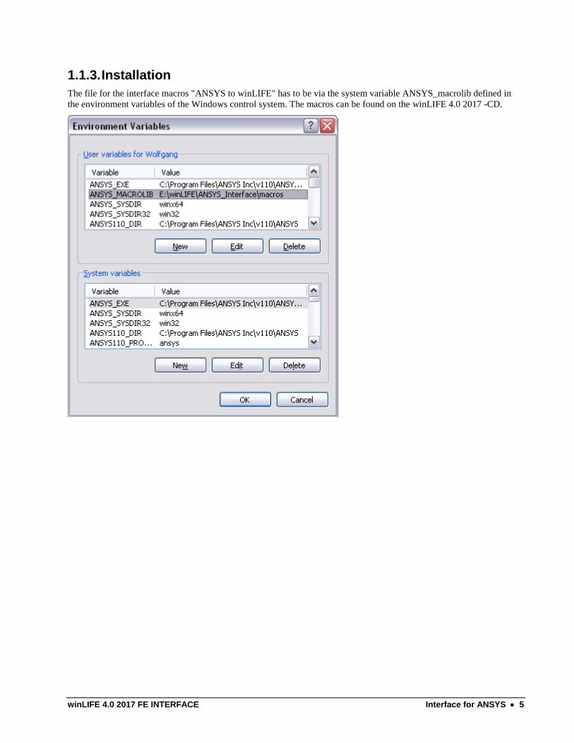
1.1.3. Installation
The file for the interface macros "ANSYS to winLIFE" has to be via the system variable ANSYS_macrolib defined in
the environment variables of the Windows control system. The macros can be found on the winLIFE 4.0 2017 -CD.
6 Interface for ANSYS winLIFE 4.0 2017 FE INTERFACE
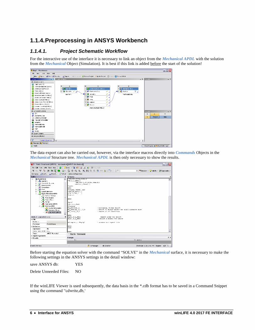
1.1.4. Preprocessing in ANSYS Workbench
1.1.4.1. Project Schematic Workflow
For the interactive use of the interface it is necessary to link an object from the Mechanical APDL with the solution
from the Mechanical Object (Simulation). It is best if this link is added before the start of the solution!
The data export can also be carried out, however, via the interface macros directly into Commands Objects in the
Mechanical Structure tree. Mechanical APDL is then only necessary to show the results.
Before starting the equation solver with the command “SOLVE" in the Mechanical surface, it is necessary to make the
following settings in the ANSYS settings in the detail window:
save ANSYS db: YES
Delete Unneeded Files: NO
If the winLIFE Viewer is used subsequently, the data basis in the *.cdb format has to be saved in a Command Snippet
using the command “cdwrite,db,‘
winLIFE 4.0 2017 FE INTERFACE Interface for ANSYS 7
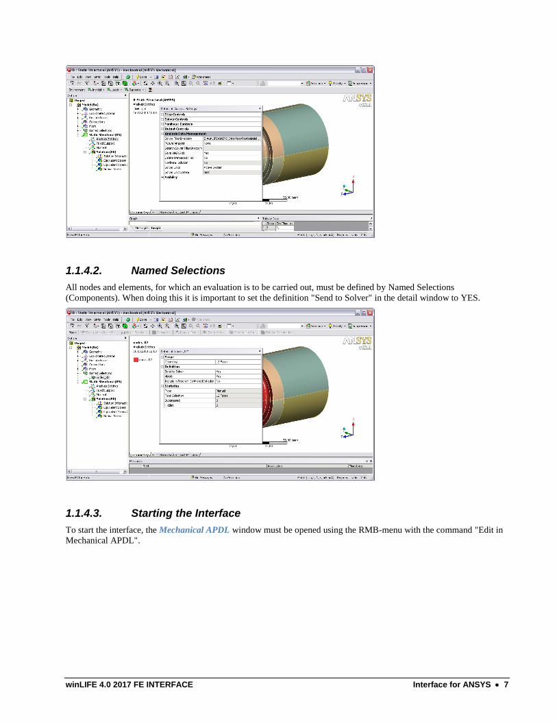
1.1.4.2. Named Selections
All nodes and elements, for which an evaluation is to be carried out, must be defined by Named Selections
(Components). When doing this it is important to set the definition "Send to Solver" in the detail window to YES.
1.1.4.3. Starting the Interface
To start the interface, the Mechanical APDL window must be opened using the RMB-menu with the command "Edit in
Mechanical APDL".
8 Interface for ANSYS winLIFE 4.0 2017 FE INTERFACE
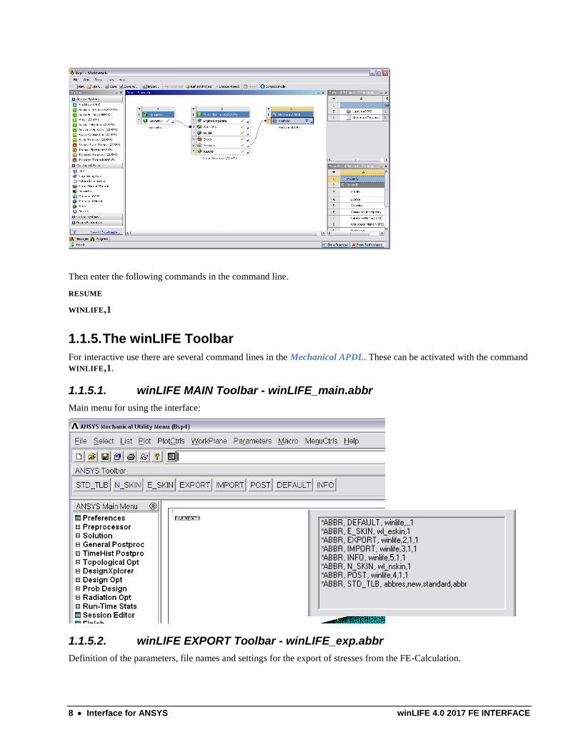
Then enter the following commands in the command line.
RESUME
WINLIFE,1
1.1.5. The winLIFE Toolbar
For interactive use there are several command lines in the Mechanical APDL. These can be activated with the command
WINLIFE,1.
1.1.5.1. winLIFE MAIN Toolbar - winLIFE_main.abbr
Main menu for using the interface:
1.1.5.2. winLIFE EXPORT Toolbar - winLIFE_exp.abbr
Definition of the parameters, file names and settings for the export of stresses from the FE-Calculation.
winLIFE 4.0 2017 FE INTERFACE Interface for ANSYS 9
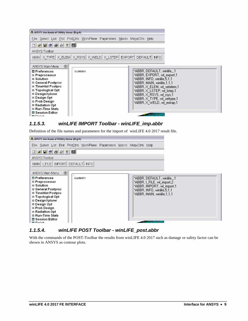
1.1.5.3. winLIFE IMPORT Toolbar - winLIFE_imp.abbr
Definition of the file names and parameters for the import of winLIFE 4.0 2017 result file.
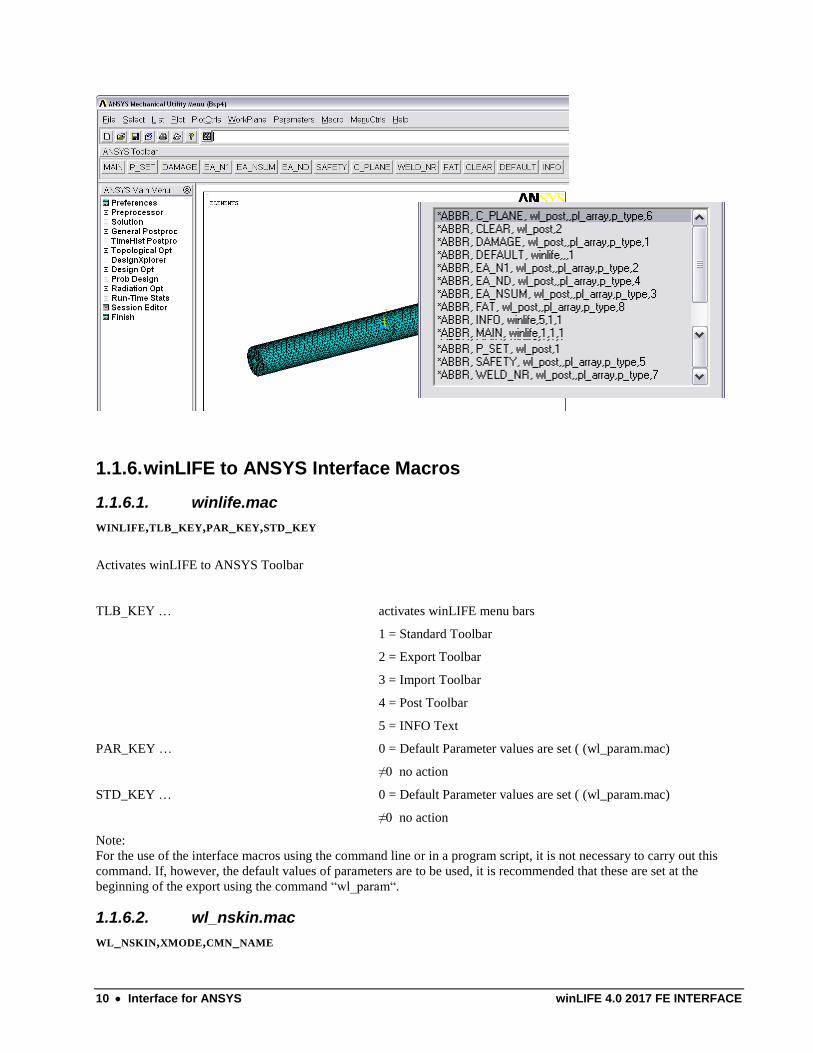
1.1.5.4. winLIFE POST Toolbar - winLIFE_post.abbr
With the commands of the POST-Toolbar the results from winLIFE 4.0 2017 such as damage or safety factor can be
shown in ANSYS as contour plots.
10 Interface for ANSYS winLIFE 4.0 2017 FE INTERFACE
1.1.6. winLIFE to ANSYS Interface Macros
1.1.6.1. winlife.mac
WINLIFE,TLB_KEY,PAR_KEY,STD_KEY
Activates winLIFE to ANSYS Toolbar
TLB_KEY … activates winLIFE menu bars
1 = Standard Toolbar
2 = Export Toolbar
3 = Import Toolbar
4 = Post Toolbar
5 = INFO Text
PAR_KEY … 0 = Default Parameter values are set ( (wl_param.mac)
≠0 no action
STD_KEY … 0 = Default Parameter values are set ( (wl_param.mac)
≠0 no action
Note:
For the use of the interface macros using the command line or in a program script, it is not necessary to carry out this
command. If, however, the default values of parameters are to be used, it is recommended that these are set at the
beginning of the export using the command “wl_param“.
1.1.6.2. wl_nskin.mac
WL_NSKIN,XMODE,CMN_NAME
winLIFE 4.0 2017 FE INTERFACE Interface for ANSYS 11
WL_NSKIN creates a node component 'cmn_name' with the “external” nodes of the
selected elements. ("External" nodes are nodes on free element surfaces.)
XMODE … Selection of the type of interactive mode
0 = Execution by command line or script
1 = activates the display of input menus
CMN_NAME … Name of the node component [Character Parameter]
Note:
When defining the component name with the command, this must be placed between two single inverted commas. (e.g.
wl_nskin,,'notch')
For the interactive definition via the dialogue field, however, you must not use these!
1.1.6.3. wl_eskin.mac
WL_ESKIN,XMODE,CMN_NAME,CME_NAME
WL_ESKIN creates shell elements for evaluating the stresses on the surface of solid
elements. This technique is also called "skinning". The nodes of the components
'cmn_name' describs the "skin" area. The elements created are grouped in the
components 'cme_name'.
XMODE … Selection of the type of interactive mode
0 = Execution by an command line or script
1 = activates the display of input menus
CMN_NAME … Name of the node component [Character Parameter]
CME_NAME … Name of the element component [Character Parameter]
Note:
When defining the component name with the command, this must be placed between two single inverted commas. (e.g.
wl_eskin,,'notch','skin')
For the interactive definition via the dialogue field, however, you must not use these!
1.1.6.4. wl_settype.mac
WL_SETTYPE,XMODE,WET
WL_SETTYPE defines the export type
XMODE … Selection of the type of interactive modus
0 = Execution by a command line or script
1 = activates the display of input menus
WET … Export type
1 = UNIAXIAL

12 Interface for ANSYS winLIFE 4.0 2017 FE INTERFACE
2 = MULTIAXIAL
3 = Weld seam extrapolation
4 = Weld seam Multiplier
5= non-linear / transient export
Note:
The export type WET=3 is currently only supported for solid elements
1.1.6.5. wl_setelem.mac
WL_SETELEM,XMODE,ESOLID,ESHELL,EBEAM,ELINK,SKINKEY
WL_SETELEM defines the element type for export
XMODE … Selection of the type of interactive modus
0 = Execution by an command line or script
1 = activates the display of input menus
ESOLID … 0/1 = No/Yes - solid elements
ESHELL … 0/1 = No/Yes - shell elements
EBEAM … 0/1 = No/Yes - beam elements (at present not yet supported)
ELINK … 0/1 = No/Yes - bar elements (at present not yet supported)
SKINKEY ... 0/1 = No / Yes – use skinning technique for solids
GRDKEY … 0/1=No/Yes – node information for stress gradient
Note:
To use the skinning technique it is necessary to pre-define the required nodes and elements using the macros
wl_nskin.mac and wl_eskin.mac
1.1.6.6. wl_rsys.mac
WL_RSYS,XMODE,CS_EXP
WL_RSYS defines the output coordinate system for the export
XMODE … Selection of the type of interactive modus
0 = Execution by an command line or script
1 = activates the display of input menus
CS_EXP … Output coordinate system
-1 = RSYS SOLU (element coordinate system)
≠-1 = Number of a defined coordinate system
Note:
When exporting unstructured meshed shell elements it is particularly important to check the result coordinate system,
because the averaged node results do not automatically take into account the different orientations of the coordinate
systems. After automatic meshing but before starting the solver it is strongly recommended to orientate the element
coordinate systems correctly!
winLIFE 4.0 2017 FE INTERFACE Interface for ANSYS 13
1.1.6.7. wl_extrap.mac
WL_EXTRAP,XMODE,XTYPE,XF_0,HSTYP,HSTHK,WLFAT,HSTOE,HSPATH,HSPLO
WL_EXTRAP defines the parameter for extrapolation for the export of weldings
Selection of the type of interactive modus
0 = Execution by an command line or script
1 = activates the display of input menus
XTYPE … Method of extrapolation
0 = automatic classification according to IIW
1 = linear extrapolation (2 reference points)
2 = quadratic extrapolation (3 reference points)
3 = rough extrapolation for coarse meshes
XF_0 ... Multiplier for multiplier method
HSTYP ... 1 = „a“ / 2 = „b“ HotSpot
HSTHK ... thickness of sheet at hot spot
WLFAT... FAT class (only for documentation)
HSTOE ... line of the foot point
HSPATH ... path of extrapolation perpendicular to the weld
HSPLO ... 0/1 = No / Yes – create a path-plot of the extrapolation
Note:
The multipliers according to the IIW recommendations are implemented within the macro. Changes of these multipliers
are only possible in the programming code.
1.1.6.8. wl_lstep.mac
WL_LSTEP,XMODE,LSSTART,LSEND
WL_LSTEP defines the area of the load cases to be exported.
XMODE … Selection of the type of interactive modus
0 = execution by a command line or script
1 = activates the display of input menus
LSSTART … first load case
LSEND ... last load case
Note:
With the two parameters LSSTART and LSEND all available load cases between these will be exported. If this is not
required, the load cases must be exported individually one after the other.
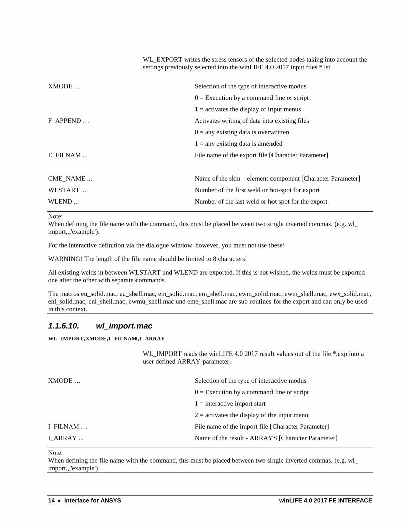
1.1.6.9. wl_export.mac
WL_EXPORT,XMODE,F_APPEND,E_FILNAM,CME_NAME,WLSTART,WLEND
14 Interface for ANSYS winLIFE 4.0 2017 FE INTERFACE
WL_EXPORT writes the stress tensors of the selected nodes taking into account the
settings previously selected into the winLIFE 4.0 2017 input files *.lst
XMODE … Selection of the type of interactive modus
0 = Execution by a command line or script
1 = activates the display of input menus
F_APPEND … Activates writing of data into existing files
0 = any existing data is overwritten
1 = any existing data is amended
E_FILNAM ... File name of the export file [Character Parameter]
CME_NAME ... Name of the skin – element component [Character Parameter]
WLSTART ... Number of the first weld or hot-spot for export
WLEND ... Number of the last weld or hot spot for the export
Note:
When defining the file name with the command, this must be placed between two single inverted commas. (e.g. wl_
import,,,'example').
For the interactive definition via the dialogue window, however, you must not use these!
WARNING! The length of the file name should be limited to 8 characters!
All existing welds in between WLSTART und WLEND are exported. If this is not wished, the welds must be exported
one after the other with separate commands.
The macros eu_solid.mac, eu_shell.mac, em_solid.mac, em_shell.mac, ewm_solid.mac, ewm_shell.mac, ewx_solid.mac,
enl_solid.mac, enl_shell.mac, ewmu_shell.mac und eme_shell.mac are sub-routines for the export and can only be used
in this context.
1.1.6.10. wl_import.mac
WL_IMPORT,XMODE,I_FILNAM,I_ARRAY
WL_IMPORT reads the winLIFE 4.0 2017 result values out of the file *.exp into a
user defined ARRAY-parameter.
XMODE … Selection of the type of interactive modus
0 = Execution by a command line or script
1 = interactive import start
2 = activates the display of the input menu
I_FILNAM … File name of the import file [Character Parameter]
I_ARRAY ... Name of the result - ARRAYS [Character Parameter]
Note:
When defining the file name with the command, this must be placed between two single inverted commas. (e.g. wl_
import,,,'example')
winLIFE 4.0 2017 FE INTERFACE Interface for ANSYS 15
For the interactive definition via the dialogue window, however, you must not use these!
WARNING! The length of the file name should be limited to 8 characters!
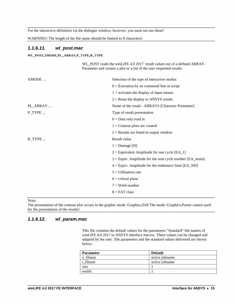
1.1.6.11. wl_post.mac
WL_POST,XMODE,PL_ARRAY,P_TYPE,R_TYPE
WL_POST reads the winLIFE 4.0 2017 result values out of a defined ARRAY-
Parameter and creates a plot or a list of the user requested results.
XMODE … Selection of the type of interactive modus
0 = Execution by an command line or script
1 = activates the display of input menus
2 = Reset the display to ANSYS results
PL_ARRAY ... Name of the result - ARRAYS [Character Parameter]
P_TYPE ... Type of result presentation
0 = Data only read in
1 = Contour plots are created
2 = Results are listed in output window
R_TYPE ... Result value
1 = Damage [D]
2 = Equivalent Amplitude for one cycle [EA_1]
3 = Equiv. Amplitude for the sum cycle number [EA_nsum]
4 = Equiv. Amplitude for the endurance limit [EA_ND]
5 = Utilisation rate
6 = critical plane
7 = Weld number
8 = FAT class
Note:
The presentation of the contour plot occurs in the graphic mode /Graphics,Full The mode /Graphics,Power cannot used
for the presentation of the results!
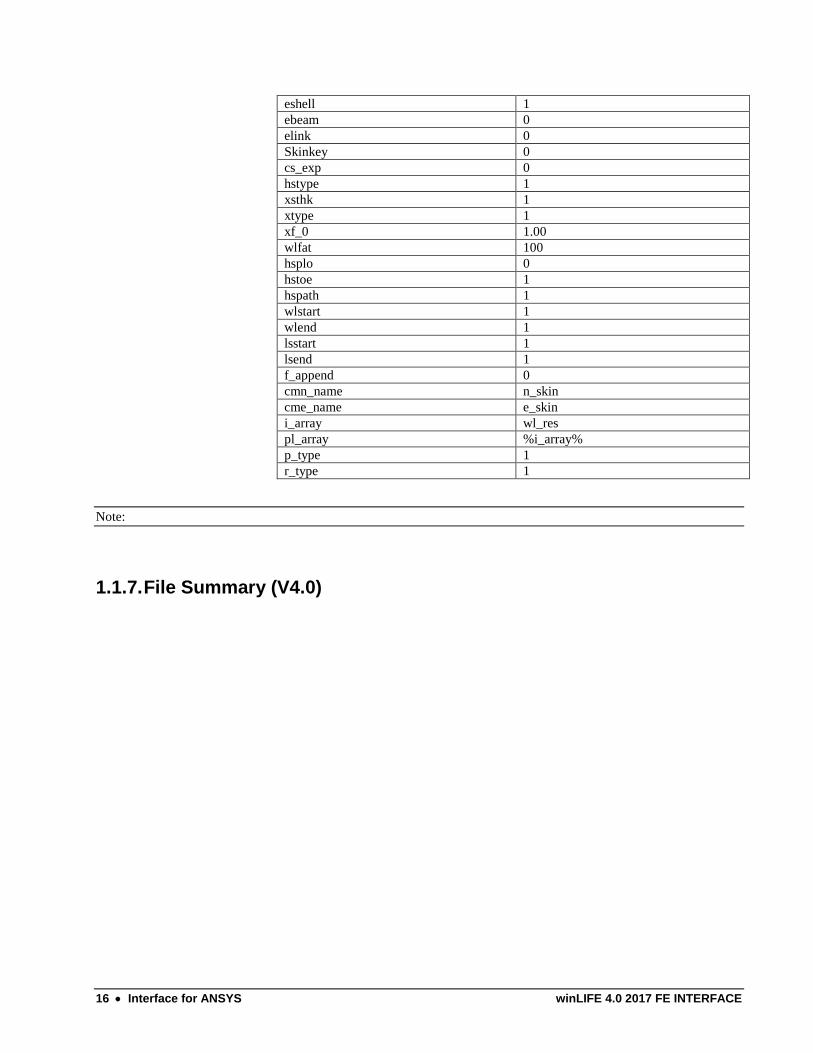
1.1.6.12. wl_param.mac
This file contains the default values for the parameters "Standard" file-names of
winLIFE 4.0 2017 to ANSYS interface macros. These values can be changed and
adapted by the user. The parameters and the standard values delivered are shown
below:
Parameter Default
e_filnam active jobname
i_filnam active jobname
wet 1
esolid 1
16 Interface for ANSYS winLIFE 4.0 2017 FE INTERFACE
eshell 1
ebeam 0
elink 0
Skinkey 0
cs_exp 0
hstype 1
xsthk 1
xtype 1
xf_0 1.00
wlfat 100
hsplo 0
hstoe 1
hspath 1
wlstart 1
wlend 1
lsstart 1
lsend 1
f_append 0
cmn_name n_skin
cme_name e_skin
i_array wl_res
pl_array %i_array%
p_type 1
r_type 1
Note:
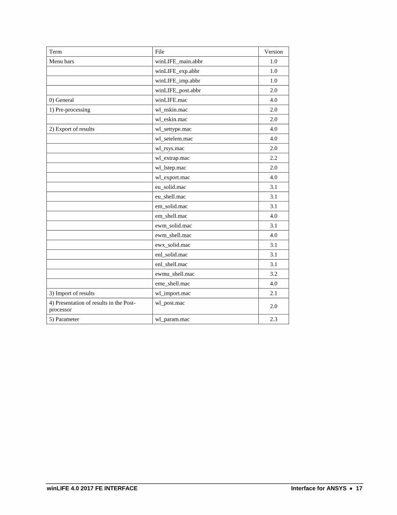
1.1.7. File Summary (V4.0)
winLIFE 4.0 2017 FE INTERFACE Interface for ANSYS 17
Term File Version
Menu bars winLIFE_main.abbr 1.0
winLIFE_exp.abbr 1.0
winLIFE_imp.abbr 1.0
winLIFE_post.abbr 2.0
0) General winLIFE.mac 4.0
1) Pre-processing wl_nskin.mac 2.0
wl_eskin.mac 2.0
2) Export of results wl_settype.mac 4.0
wl_setelem.mac 4.0
wl_rsys.mac 2.0
wl_extrap.mac 2.2
wl_lstep.mac 2.0
wl_export.mac 4.0
eu_solid.mac 3.1
eu_shell.mac 3.1
em_solid.mac 3.1
em_shell.mac 4.0
ewm_solid.mac 3.1
ewm_shell.mac 4.0
ewx_solid.mac 3.1
enl_solid.mac 3.1
enl_shell.mac 3.1
ewmu_shell.mac 3.2
eme_shell.mac 4.0
3) Import of results wl_import.mac 2.1
4) Presentation of results in the Post-
processor
wl_post.mac 2.0
5) Parameter wl_param.mac 2.3


winLIFE 4.0 2017 FE INTERFACE FEMAP Installation notes and Interface 19
2. FEMAP Installation notes and Interface
All existing modules of winLIFE 4.0 2017 :
winLIFE FKM QUICKCHECK
winLIFE 4.0 2017
winLIFE GEARWHEEL&BEARING
winLIFE MULTIAXIAL
winLIFE MULTIAXIAL MULTICORE
VIEWER4WINLIFE
winLIFE CRACKGROWTH
winLIFE RANDOM FATIQUE
are all on the installation-CD and are installed during the installation process. They are inaccessible, however, until you
buy a license and register with winLIFE 4.0 2017 .
winLIFE 4.0 2017 can be used with
NX NASTRAN
NEi NASTRAN
The two programs use FEMAP as a pre and postprocessor. This leads to a totally identical data structure. Other
programs which use FEMAP can be connected to winLIFE 4.0 2017 without problems.
The installation process of winLIFE 4.0 2017 itself has been described before. In this chapter the interface to FEMAP is
described.
20 FEMAP Installation notes and Interface winLIFE 4.0 2017 FE INTERFACE
2.1. Standard Interface (recommended) Execute the file
winLIFE_interface_to_FEMAP.exe
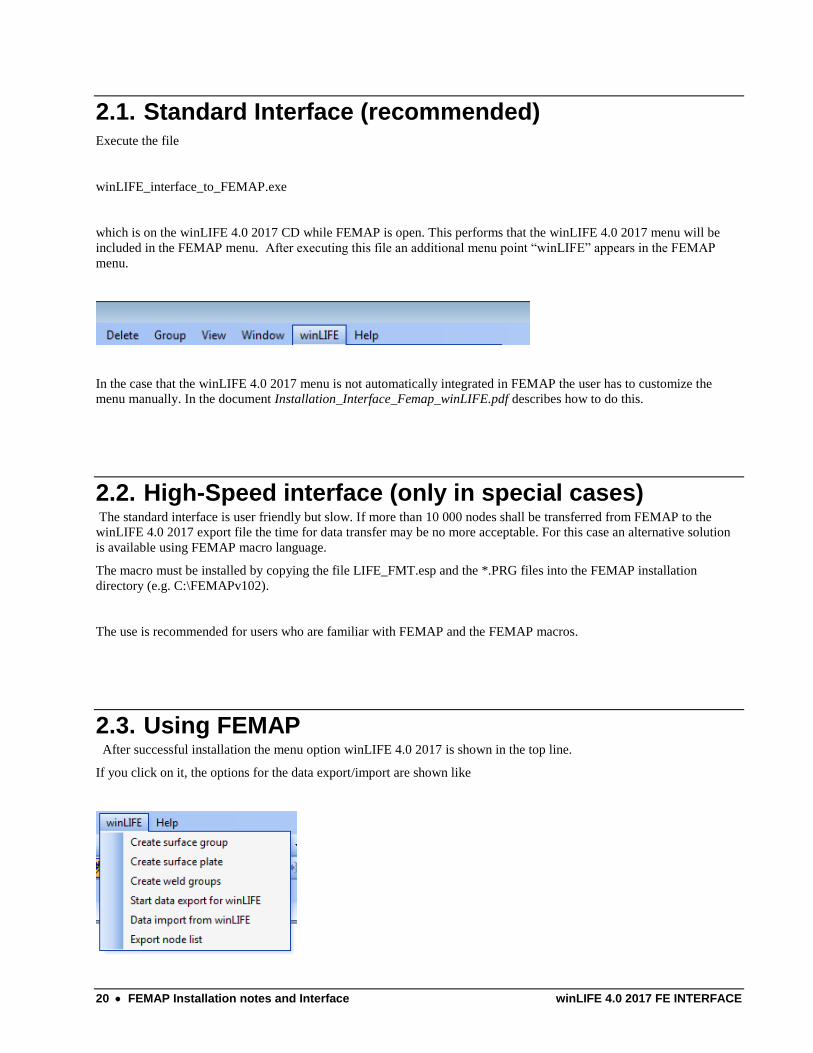
which is on the winLIFE 4.0 2017 CD while FEMAP is open. This performs that the winLIFE 4.0 2017 menu will be
included in the FEMAP menu. After executing this file an additional menu point “winLIFE” appears in the FEMAP
menu.
In the case that the winLIFE 4.0 2017 menu is not automatically integrated in FEMAP the user has to customize the
menu manually. In the document Installation_Interface_Femap_winLIFE.pdf describes how to do this.
2.2. High-Speed interface (only in special cases) The standard interface is user friendly but slow. If more than 10 000 nodes shall be transferred from FEMAP to the
winLIFE 4.0 2017 export file the time for data transfer may be no more acceptable. For this case an alternative solution
is available using FEMAP macro language.
The macro must be installed by copying the file LIFE_FMT.esp and the *.PRG files into the FEMAP installation
directory (e.g. C:\FEMAPv102).
The use is recommended for users who are familiar with FEMAP and the FEMAP macros.
2.3. Using FEMAP After successful installation the menu option winLIFE 4.0 2017 is shown in the top line.
If you click on it, the options for the data export/import are shown like
winLIFE 4.0 2017 FE INTERFACE FEMAP Installation notes and Interface 21
Figure 2-1: winLIFE-Button and sub-menus in the user-interface of FEMAP (is created while the installation process of winLIFE)
2.3.1. Create Surface Group
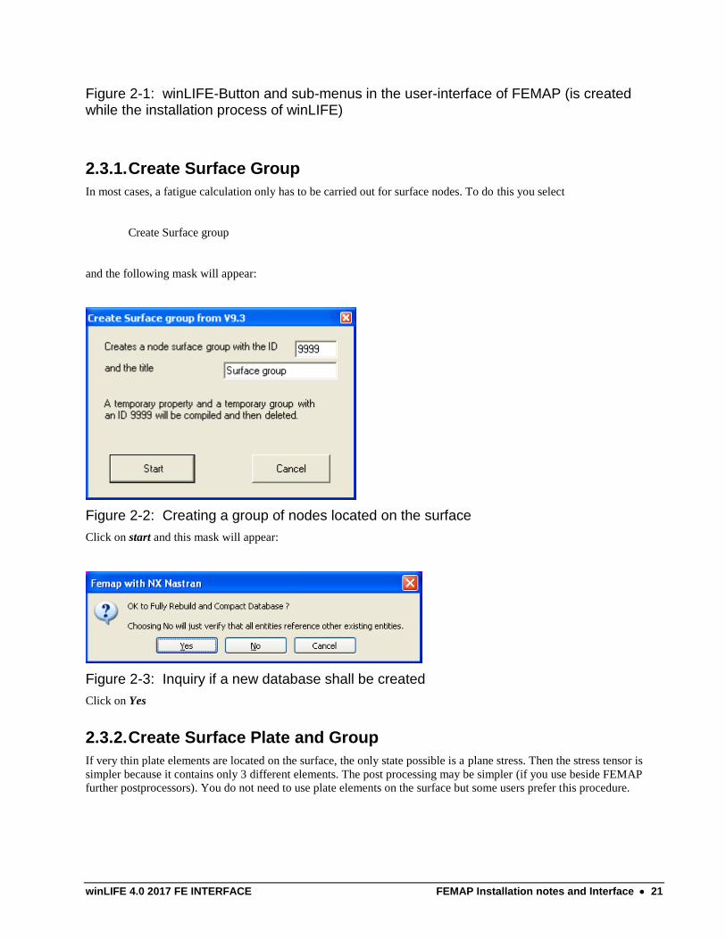
In most cases, a fatigue calculation only has to be carried out for surface nodes. To do this you select
Create Surface group
and the following mask will appear:
Figure 2-2: Creating a group of nodes located on the surface
Click on start and this mask will appear:
Figure 2-3: Inquiry if a new database shall be created
Click on Yes
2.3.2. Create Surface Plate and Group
If very thin plate elements are located on the surface, the only state possible is a plane stress. Then the stress tensor is
simpler because it contains only 3 different elements. The post processing may be simpler (if you use beside FEMAP
further postprocessors). You do not need to use plate elements on the surface but some users prefer this procedure.
22 FEMAP Installation notes and Interface winLIFE 4.0 2017 FE INTERFACE
Figure 2-4: Inquiry to create thin plate elements on the surface
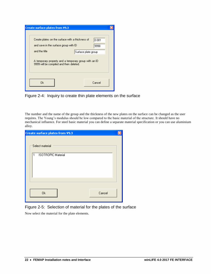
The number and the name of the group and the thickness of the new plates on the surface can be changed as the user
requires. The Young’s modulus should be low compared to the basic material of the structure. It should have no
mechanical influence. For steel basic material you can define a separate material specification or you can use aluminium
alloy.
Figure 2-5: Selection of material for the plates of the surface
Now select the material for the plate elements.
winLIFE 4.0 2017 FE INTERFACE FEMAP Installation notes and Interface 23
Figure 2-6: Selection of the plate elements on the surface
Select the elements you are interested in.
Figure 2-7: Inquiry if a new database shall be created
Click on Yes to continue.
2.3.3. Create Weld Groups
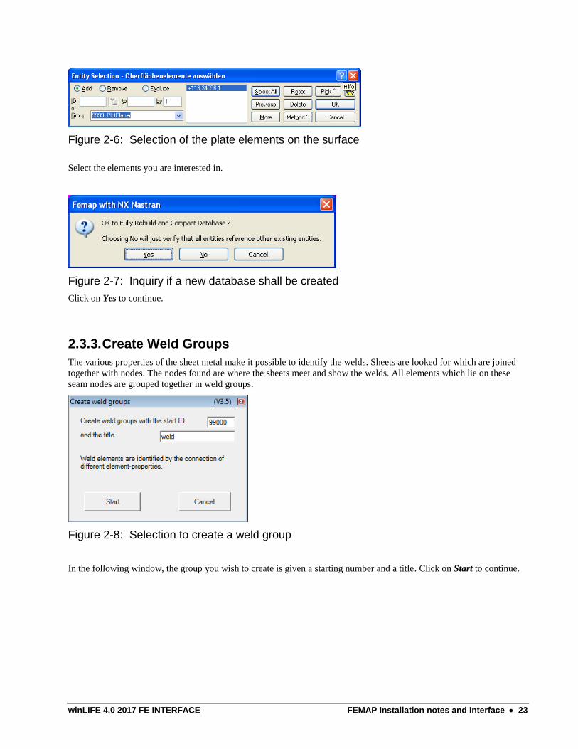
The various properties of the sheet metal make it possible to identify the welds. Sheets are looked for which are joined
together with nodes. The nodes found are where the sheets meet and show the welds. All elements which lie on these
seam nodes are grouped together in weld groups.
Figure 2-8: Selection to create a weld group
In the following window, the group you wish to create is given a starting number and a title. Click on Start to continue.
24 FEMAP Installation notes and Interface winLIFE 4.0 2017 FE INTERFACE
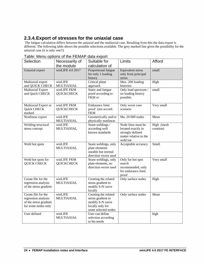
2.3.4. Export of stresses for the uniaxial case The fatigue calculation differs between the uniaxial and the multiaxial case. Resulting from this the data export is
different. The following table shows the possible selections available. The grey marked line gives the possibility for the
uniaxial case (it is only one!!)
Table: Menu options of the FEMAP data export
Selection Necessarity of the module
Suitable for calculation of
Limits Afford
Uniaxial export winLIFE 4.0 2017 Proportional fatigue
for only 1 loading
history
Equivalent stress
only from principal
stress
small
Multiaxial export
and QUICK CHECK
winLIFE
MULTIAXIAL
Critical plane
approach
Max. 200 loading
histories
High
Multiaxial Export
and Quick CHECK winLIFE FKM
QUICKCHECK
Static and fatigue
proof according to
FKM or
Only load spectrum /
no loading history
possible.
small
Multiaxial Export or
Quick CHECK
marked
winLIFE FKM
QUICKCHECK
Endurance limit
proof (not accord.
FKM
Only worst case
scenario
Very small
Nonlinear export winLIFE
MULTIAXIAL
Geometrically and/or
physically nonlinear
Ma. 20 000 nodes Mean
Welding structural
stress concept winLIFE
MULTIAXIAL
Seam weldings /
according well
known standards
Node lines must be
located exactly in
strongly defined
matter relative to the
weld toe
High (mesh
creation)
Weld hot spots winLIFE
MULTIAXIAL
Seam weldings, only
plate elements
useable but normal
direction vector used
Acceptable accuracy Small
Weld hot spots for
QUICK CHECK
winLIFE FKM
QUICKCHECK
Seam weldings, only
plate elements, no
direction vector used
Only for hot spot
search
recommended, only
for endurance limit
proof
Very small
Create file for the
regression analysis
of the stress gradient
winLIFE
MULTIAXIAL
Creating the related
stress gradient to
modify S-N curve
locally
Only surface nodes High
Create file for the
regression analysis
of the stress gradient
for some nodes only
winLIFE
MULTIAXIAL
Creating the related
stress gradient to
modify S-N curve
locally only for
some selected nodes
Only surface nodes Mean
User defined winLIFE
MULTIAXIAL
User can define
selection according
to his needs
high
winLIFE 4.0 2017 FE INTERFACE FEMAP Installation notes and Interface 25
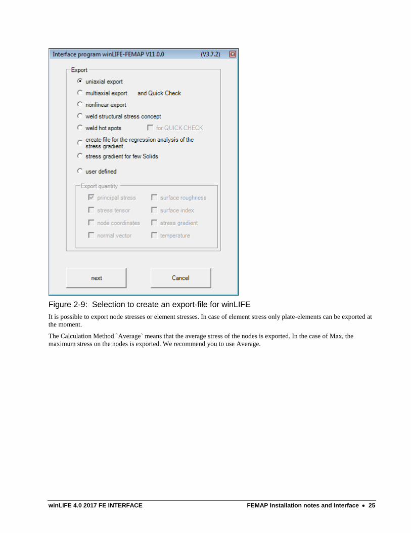
Figure 2-9: Selection to create an export-file for winLIFE
It is possible to export node stresses or element stresses. In case of element stress only plate-elements can be exported at
the moment.
The Calculation Method `Average` means that the average stress of the nodes is exported. In the case of Max, the
maximum stress on the nodes is exported. We recommend you to use Average.
26 FEMAP Installation notes and Interface winLIFE 4.0 2017 FE INTERFACE
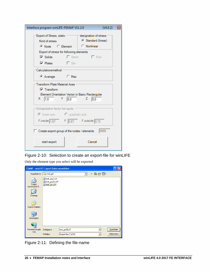
Figure 2-10: Selection to create an export-file for winLIFE
Only the element type you select will be exported
Figure 2-11: Defining the file-name
winLIFE 4.0 2017 FE INTERFACE FEMAP Installation notes and Interface 27
The filename and the directory are chosen by the user. Keep the name in your mind, because you have to select the file
later.
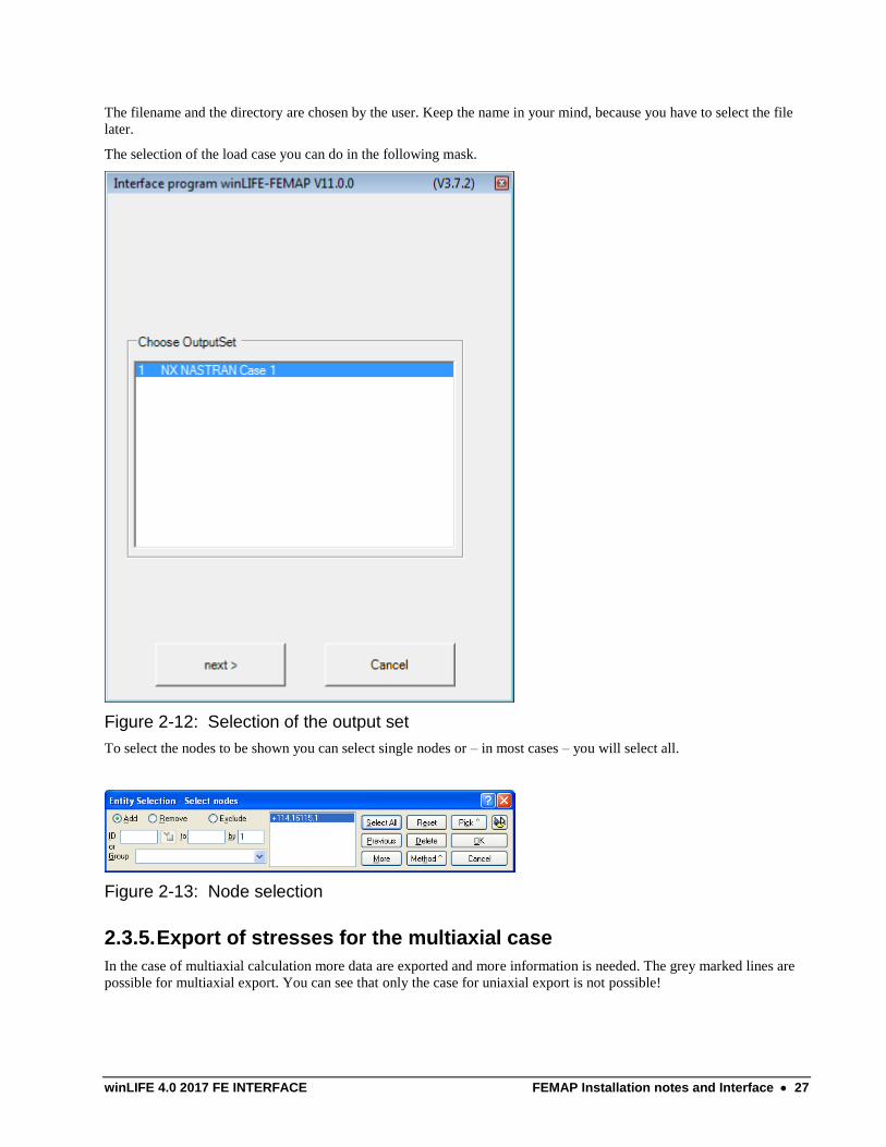
The selection of the load case you can do in the following mask.
Figure 2-12: Selection of the output set
To select the nodes to be shown you can select single nodes or – in most cases – you will select all.
Figure 2-13: Node selection
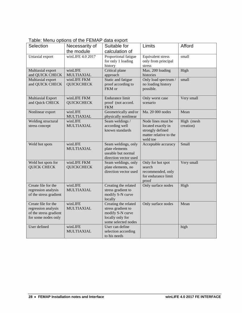
2.3.5. Export of stresses for the multiaxial case
In the case of multiaxial calculation more data are exported and more information is needed. The grey marked lines are
possible for multiaxial export. You can see that only the case for uniaxial export is not possible!
28 FEMAP Installation notes and Interface winLIFE 4.0 2017 FE INTERFACE
Table: Menu options of the FEMAP data export
Selection Necessarity of the module
Suitable for calculation of
Limits Afford
Uniaxial export winLIFE 4.0 2017 Proportional fatigue
for only 1 loading
history
Equivalent stress
only from principal
stress
small
Multiaxial export
and QUICK CHECK
winLIFE
MULTIAXIAL
Critical plane
approach
Max. 200 loading
histories
High
Multiaxial export
and QUICK CHECK
winLIFE FKM
QUICKCHECK
Static and fatigue
proof according to
FKM or
Only load spectrum /
no loading history
possible.
small
Multiaxial Export
and Quick CHECK winLIFE FKM
QUICKCHECK
Endurance limit
proof (not accord.
FKM
Only worst case
scenario
Very small
Nonlinear export winLIFE
MULTIAXIAL
Geometrically and/or
physically nonlinear
Ma. 20 000 nodes Mean
Welding structural
stress concept winLIFE
MULTIAXIAL
Seam weldings /
according well
known standards
Node lines must be
located exactly in
strongly defined
matter relative to the
weld toe
High (mesh
creation)
Weld hot spots winLIFE
MULTIAXIAL
Seam weldings, only
plate elements
useable but normal
direction vector used
Acceptable accuracy Small
Weld hot spots for
QUICK CHECK
winLIFE FKM
QUICKCHECK
Seam weldings, only
plate elements, no
direction vector used
Only for hot spot
search
recommended, only
for endurance limit
proof
Very small
Create file for the
regression analysis
of the stress gradient
winLIFE
MULTIAXIAL
Creating the related
stress gradient to
modify S-N curve
locally
Only surface nodes High
Create file for the
regression analysis
of the stress gradient
for some nodes only
winLIFE
MULTIAXIAL
Creating the related
stress gradient to
modify S-N curve
locally only for
some selected nodes
Only surface nodes Mean
User defined winLIFE
MULTIAXIAL
User can define
selection according
to his needs
high
winLIFE 4.0 2017 FE INTERFACE FEMAP Installation notes and Interface 29
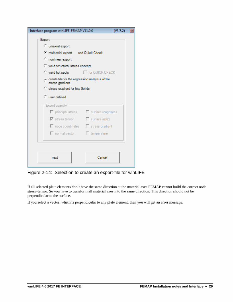
Figure 2-14: Selection to create an export-file for winLIFE
If all selected plate elements don`t have the same direction at the material axes FEMAP cannot build the correct node
stress–tensor. So you have to transform all material axes into the same direction. This direction should not be
perpendicular to the surface.
If you select a vector, which is perpendicular to any plate element, then you will get an error message.
30 FEMAP Installation notes and Interface winLIFE 4.0 2017 FE INTERFACE
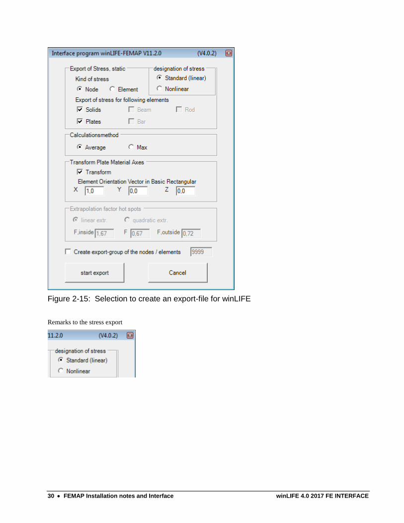
Figure 2-15: Selection to create an export-file for winLIFE
Remarks to the stress export
winLIFE 4.0 2017 FE INTERFACE FEMAP Installation notes and Interface 31
Selecting Standard linear in a multiaxial export the following vectors are exported:
Solid-Elements Shell elements
If the kind of stress is Nonlinear the following vectors are exported::
Solid-Element type Shell elements
In the case of uniaxial export the principal stresses (linear, nonlinear) are exported.
Note: Results from ADINA are listed as nonlinear stresses in Femap
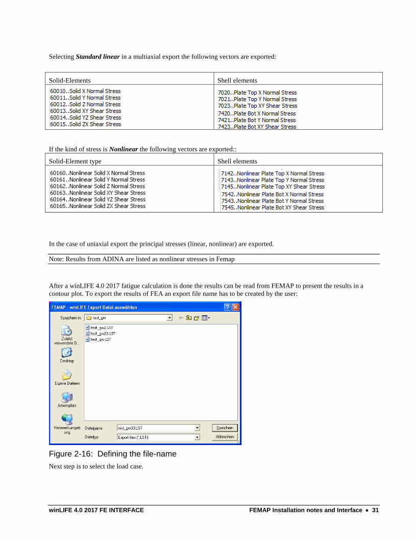
After a winLIFE 4.0 2017 fatigue calculation is done the results can be read from FEMAP to present the results in a
contour plot. To export the results of FEA an export file name has to be created by the user:
Figure 2-16: Defining the file-name
Next step is to select the load case.
32 FEMAP Installation notes and Interface winLIFE 4.0 2017 FE INTERFACE
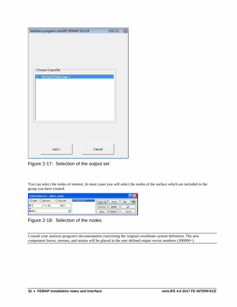
Figure 2-17: Selection of the output set
You can select the nodes of interest. In most cases you will select the nodes of the surface which are included in the
group you have created.
Figure 2-18: Selection of the nodes
Consult your analysis program's documentation concerning the original coordinate system definition. The new
component forces, stresses, and strains will be placed in the user defined output vector numbers (300000+).
winLIFE 4.0 2017 FE INTERFACE FEMAP Installation notes and Interface 33
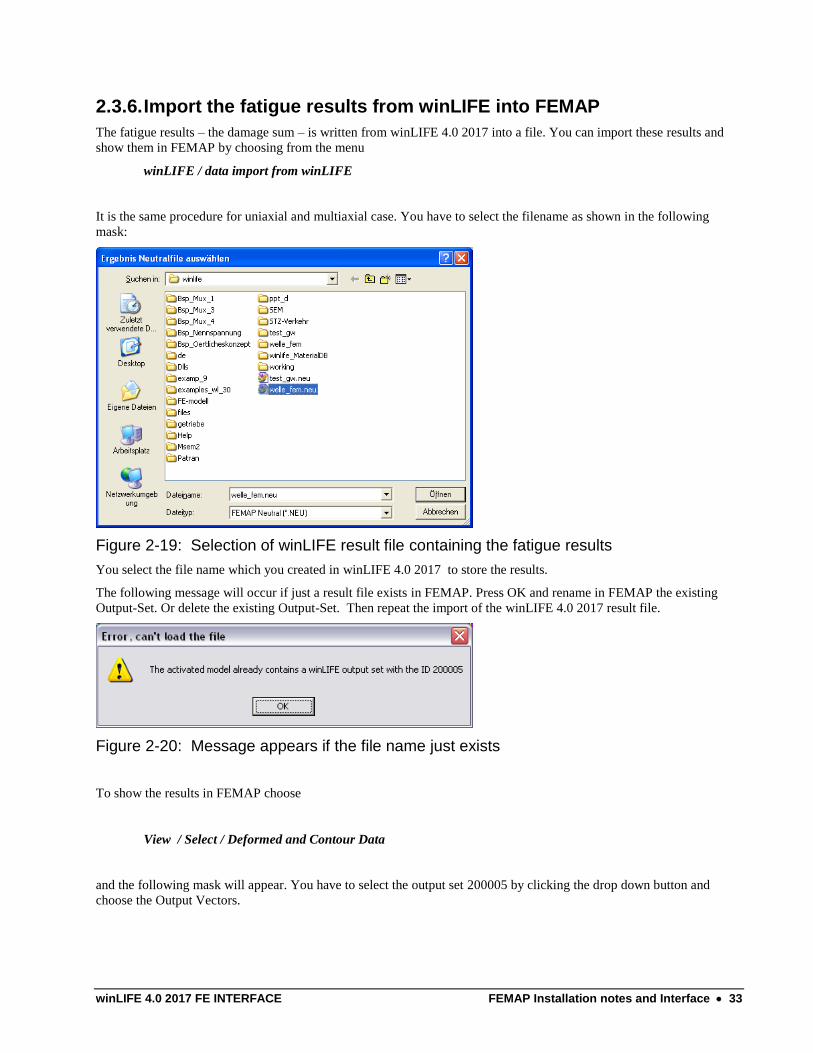
2.3.6. Import the fatigue results from winLIFE into FEMAP
The fatigue results – the damage sum – is written from winLIFE 4.0 2017 into a file. You can import these results and
show them in FEMAP by choosing from the menu
winLIFE / data import from winLIFE
It is the same procedure for uniaxial and multiaxial case. You have to select the filename as shown in the following
mask:
Figure 2-19: Selection of winLIFE result file containing the fatigue results
You select the file name which you created in winLIFE 4.0 2017 to store the results.
The following message will occur if just a result file exists in FEMAP. Press OK and rename in FEMAP the existing
Output-Set. Or delete the existing Output-Set. Then repeat the import of the winLIFE 4.0 2017 result file.
Figure 2-20: Message appears if the file name just exists
To show the results in FEMAP choose
View / Select / Deformed and Contour Data
and the following mask will appear. You have to select the output set 200005 by clicking the drop down button and
choose the Output Vectors.
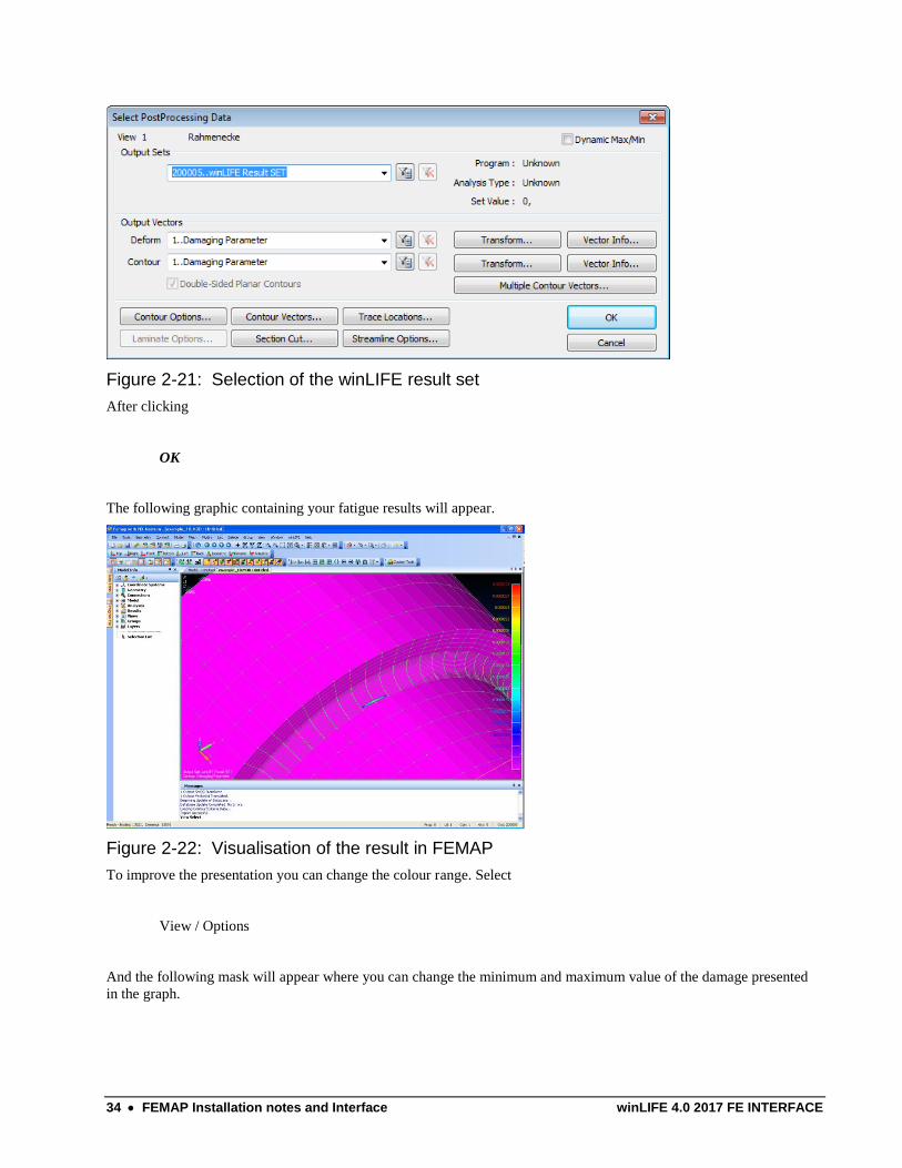
34 FEMAP Installation notes and Interface winLIFE 4.0 2017 FE INTERFACE
Figure 2-21: Selection of the winLIFE result set
After clicking
OK
The following graphic containing your fatigue results will appear.
Figure 2-22: Visualisation of the result in FEMAP
To improve the presentation you can change the colour range. Select
View / Options
And the following mask will appear where you can change the minimum and maximum value of the damage presented
in the graph.
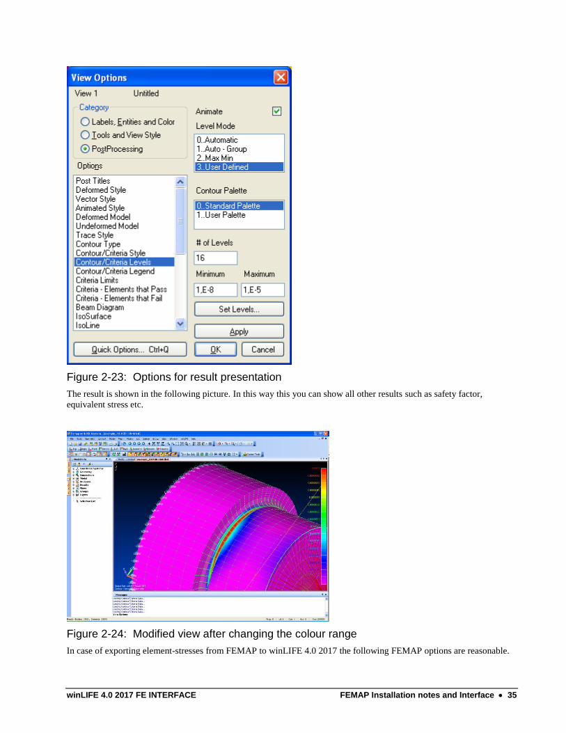
winLIFE 4.0 2017 FE INTERFACE FEMAP Installation notes and Interface 35
Figure 2-23: Options for result presentation
The result is shown in the following picture. In this way this you can show all other results such as safety factor,
equivalent stress etc.
Figure 2-24: Modified view after changing the colour range
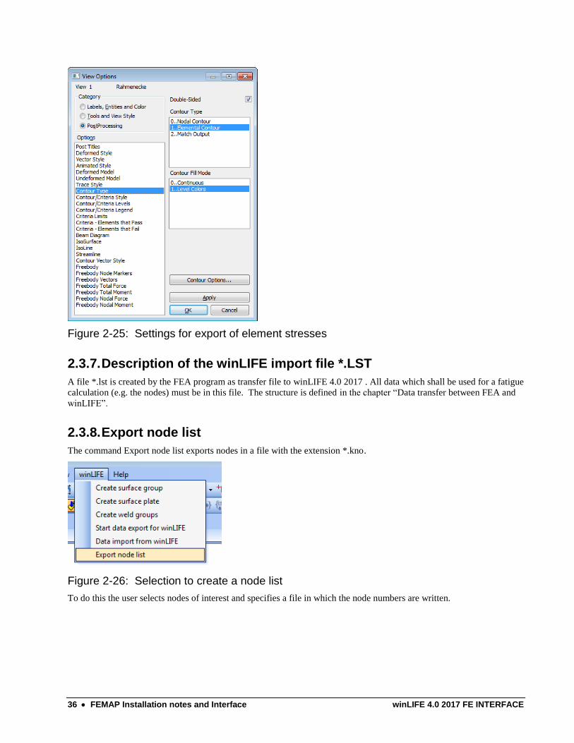
In case of exporting element-stresses from FEMAP to winLIFE 4.0 2017 the following FEMAP options are reasonable.
36 FEMAP Installation notes and Interface winLIFE 4.0 2017 FE INTERFACE
Figure 2-25: Settings for export of element stresses
2.3.7. Description of the winLIFE import file *.LST
A file *.lst is created by the FEA program as transfer file to winLIFE 4.0 2017 . All data which shall be used for a fatigue
calculation (e.g. the nodes) must be in this file. The structure is defined in the chapter “Data transfer between FEA and
winLIFE”.
2.3.8. Export node list
The command Export node list exports nodes in a file with the extension *.kno.
Figure 2-26: Selection to create a node list
To do this the user selects nodes of interest and specifies a file in which the node numbers are written.
winLIFE 4.0 2017 FE INTERFACE FEMAP Installation notes and Interface 37
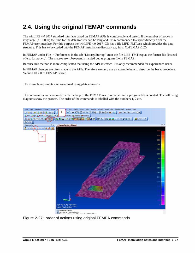
2.4. Using the original FEMAP commands
The winLIFE 4.0 2017 standard interface based on FEMAP APIs is comfortable and tested. If the number of nodes is
very large (> 10 000) the time for the data transfer can be long and it is recommended to export directly from the
FEMAP user interface. For this purpose the winLIFE 4.0 2017 CD has a file LIFE_FMT.esp which provides the data
structure. This has to be copied into the FEMAP installation directory e.g. into: C:\FEMAPv102\.
In FEMAP under File -> Preferences in the tab "Library/Startup" enter the file LIFE_FMT.esp as the format file (instead
of e.g. format.esp). The macros are subsequently carried out as program file in FEMAP.
Because this method is more complicated that using the API-interface, it is only recommended for experienced users.
In FEMAP changes are often made to the APIs. Therefore we only use an example here to describe the basic procedure.
Version 10.2.0 of FEMAP is used.
The example represents a uniaxial load using plate elements.
The commands can be recorded with the help of the FEMAP macro recorder and a program file is created. The following
diagrams show the process. The order of the commands is labelled with the numbers 1, 2 etc.
Figure 2-27: order of actions using original FEMPA commands
38 FEMAP Installation notes and Interface winLIFE 4.0 2017 FE INTERFACE
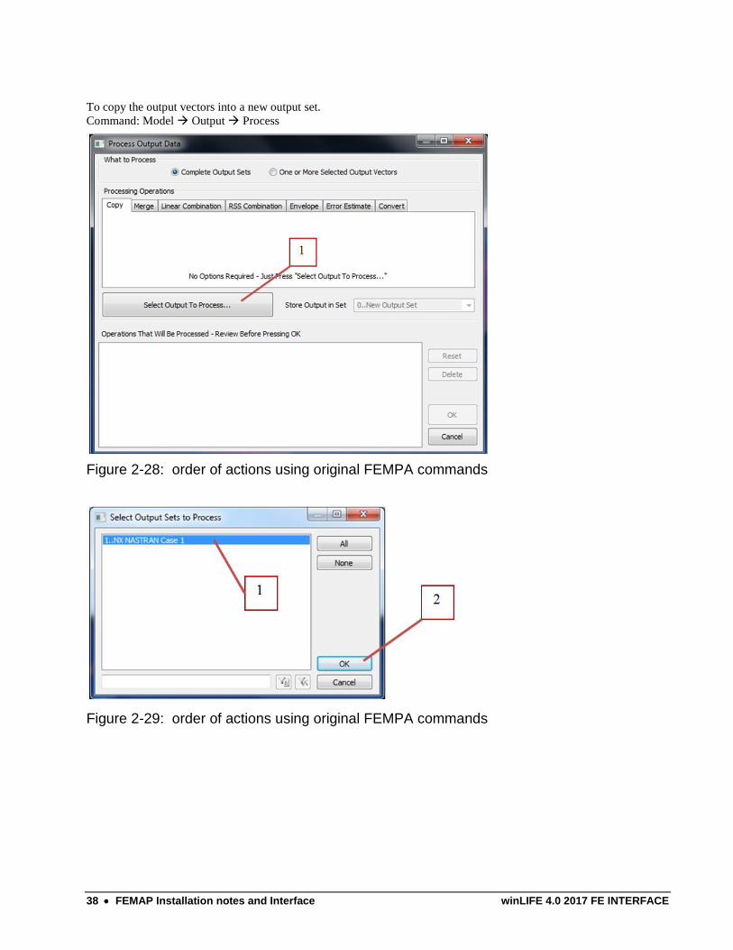
To copy the output vectors into a new output set.
Command: Model Output Process
Figure 2-28: order of actions using original FEMPA commands
Figure 2-29: order of actions using original FEMPA commands
winLIFE 4.0 2017 FE INTERFACE FEMAP Installation notes and Interface 39
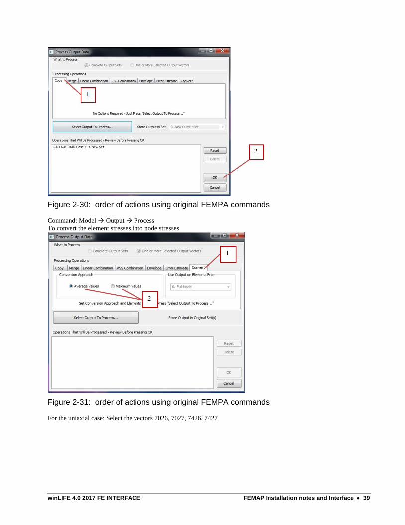
Figure 2-30: order of actions using original FEMPA commands
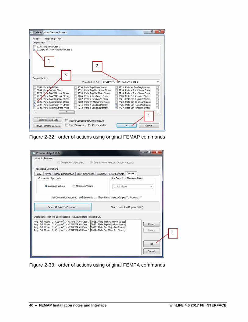
Command: Model Output Process
To convert the element stresses into node stresses
Figure 2-31: order of actions using original FEMPA commands
For the uniaxial case: Select the vectors 7026, 7027, 7426, 7427
40 FEMAP Installation notes and Interface winLIFE 4.0 2017 FE INTERFACE
Figure 2-32: order of actions using original FEMAP commands
Figure 2-33: order of actions using original FEMPA commands

winLIFE 4.0 2017 FE INTERFACE FEMAP Installation notes and Interface 41
42 FEMAP Installation notes and Interface winLIFE 4.0 2017 FE INTERFACE
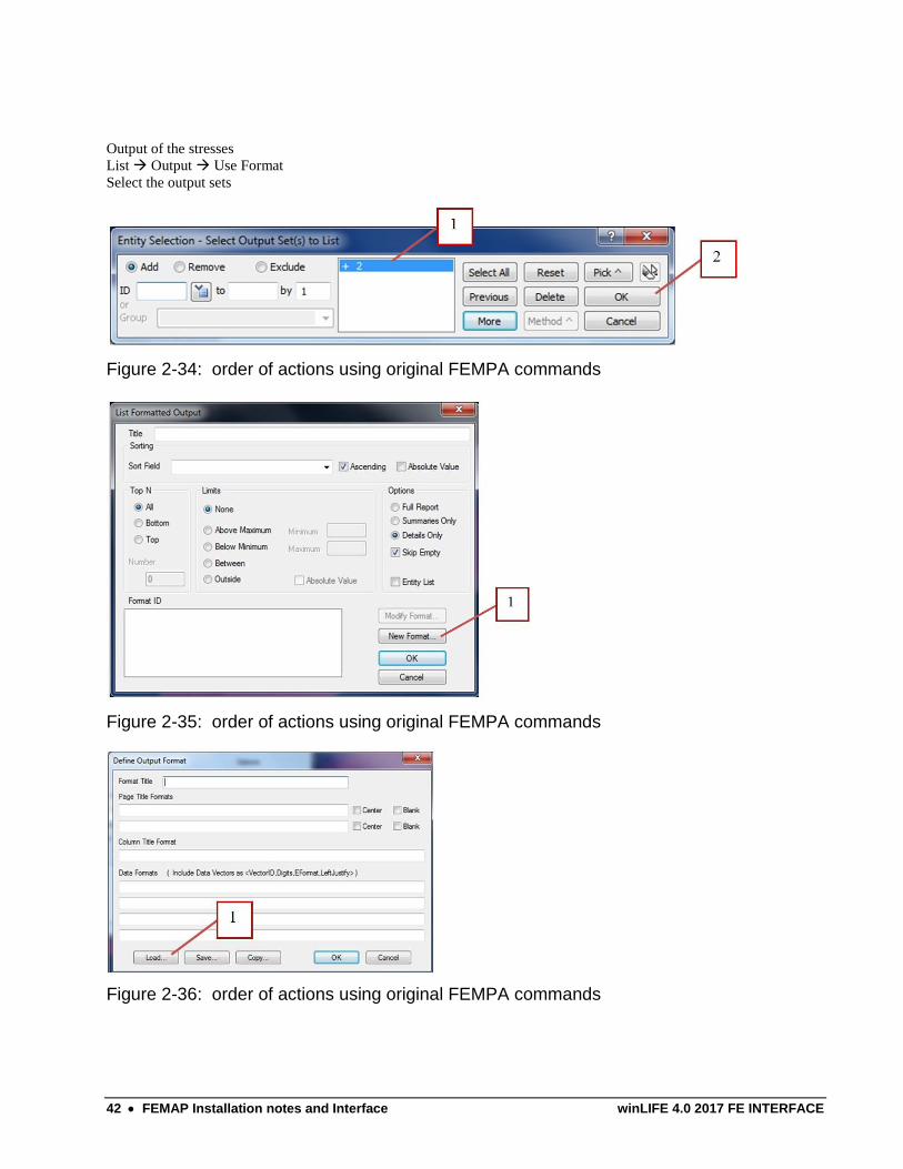
Output of the stresses
List Output Use Format
Select the output sets
Figure 2-34: order of actions using original FEMPA commands
Figure 2-35: order of actions using original FEMPA commands
Figure 2-36: order of actions using original FEMPA commands
winLIFE 4.0 2017 FE INTERFACE FEMAP Installation notes and Interface 43
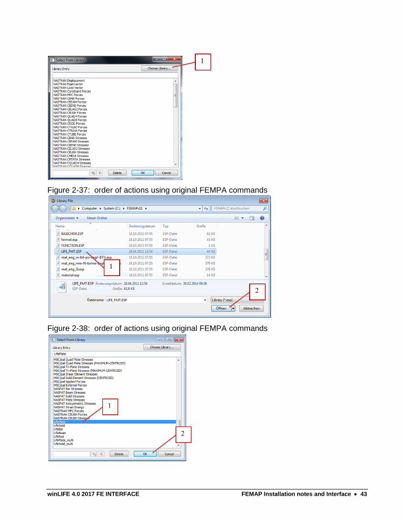
Figure 2-37: order of actions using original FEMPA commands
Figure 2-38: order of actions using original FEMPA commands

44 FEMAP Installation notes and Interface winLIFE 4.0 2017 FE INTERFACE
Figure 2-39: order of actions using original FEMPA commands
winLIFE 4.0 2017 FE INTERFACE FEMAP Installation notes and Interface 45
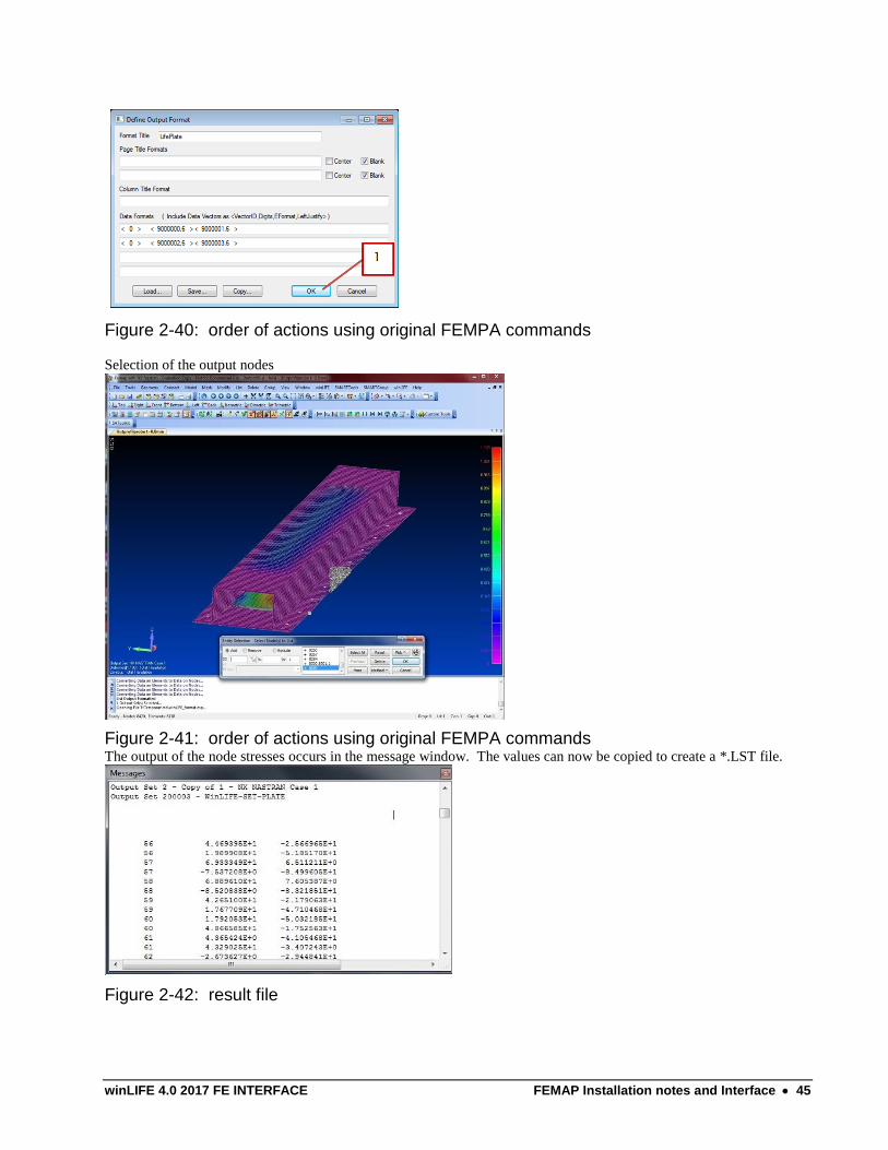
Figure 2-40: order of actions using original FEMPA commands
Selection of the output nodes
Figure 2-41: order of actions using original FEMPA commands The output of the node stresses occurs in the message window. The values can now be copied to create a *.LST file.
Figure 2-42: result file

winLIFE 4.0 2017 FE INTERFACE ADINA Data export to winLIFE 47
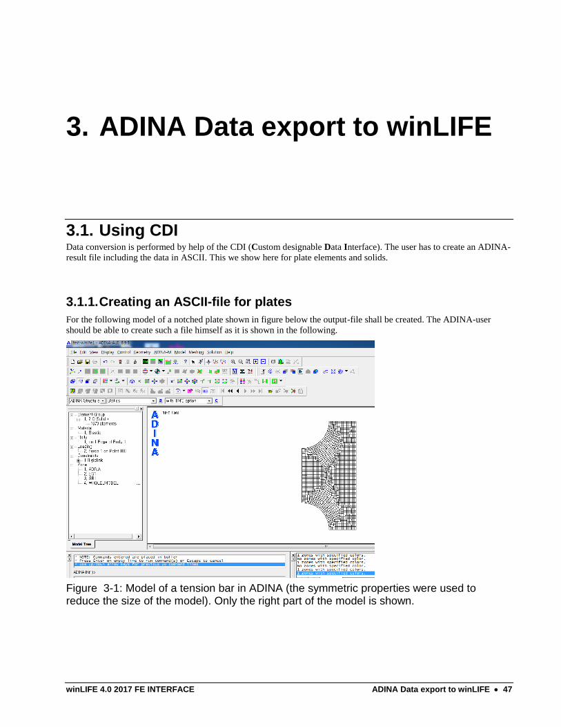
3. ADINA Data export to winLIFE
3.1. Using CDI Data conversion is performed by help of the CDI (Custom designable Data Interface). The user has to create an ADINA-
result file including the data in ASCII. This we show here for plate elements and solids.
3.1.1. Creating an ASCII-file for plates
For the following model of a notched plate shown in figure below the output-file shall be created. The ADINA-user
should be able to create such a file himself as it is shown in the following.
Figure 3-1: Model of a tension bar in ADINA (the symmetric properties were used to reduce the size of the model). Only the right part of the model is shown.
48 ADINA Data export to winLIFE winLIFE 4.0 2017 FE INTERFACE
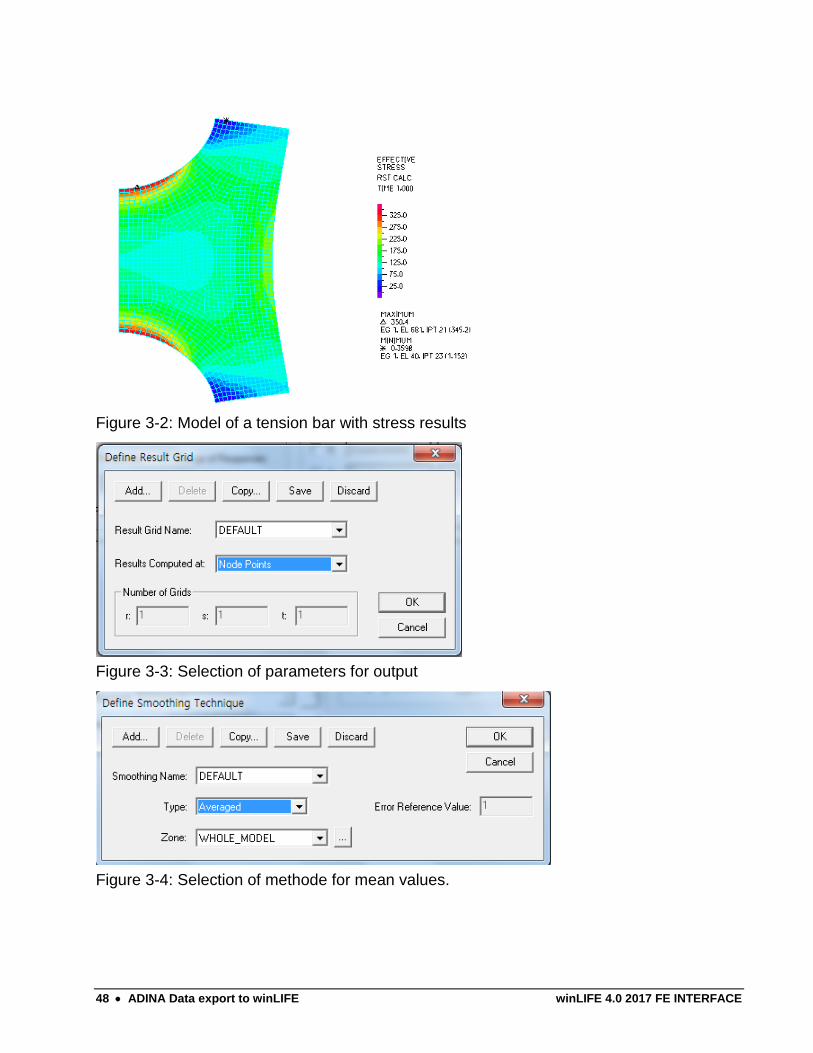
Figure 3-2: Model of a tension bar with stress results
Figure 3-3: Selection of parameters for output
Figure 3-4: Selection of methode for mean values.
winLIFE 4.0 2017 FE INTERFACE ADINA Data export to winLIFE 49
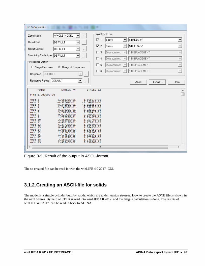
Figure 3-5: Result of the output in ASCII-format
The so created file can be read in with the winLIFE 4.0 2017 CDI.
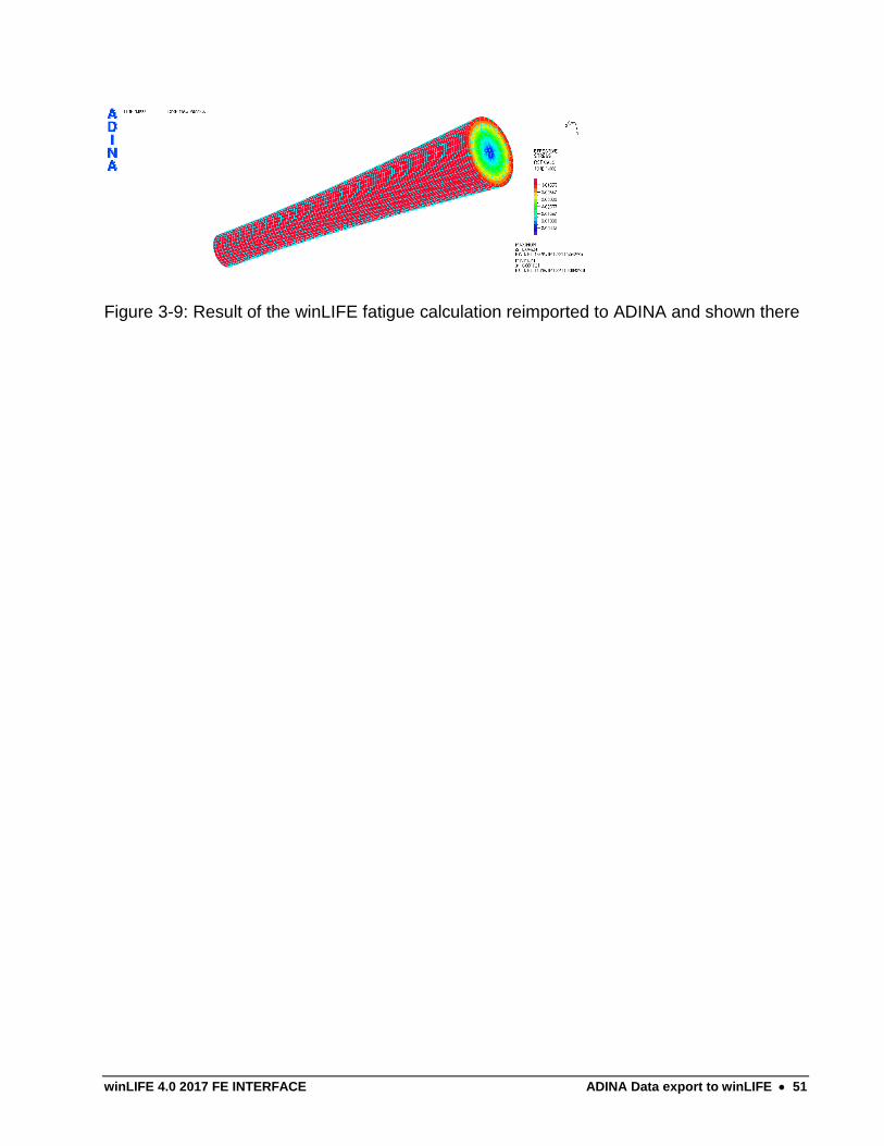
3.1.2. Creating an ASCII-file for solids
The model is a simple cylinder built by solids, which are under tension stresses. How to create the ASCII file is shown in
the next figures. By help of CDI it is read into winLIFE 4.0 2017 and the fatigue calculation is done. The results of
winLIFE 4.0 2017 can be read in back to ADINA.
50 ADINA Data export to winLIFE winLIFE 4.0 2017 FE INTERFACE
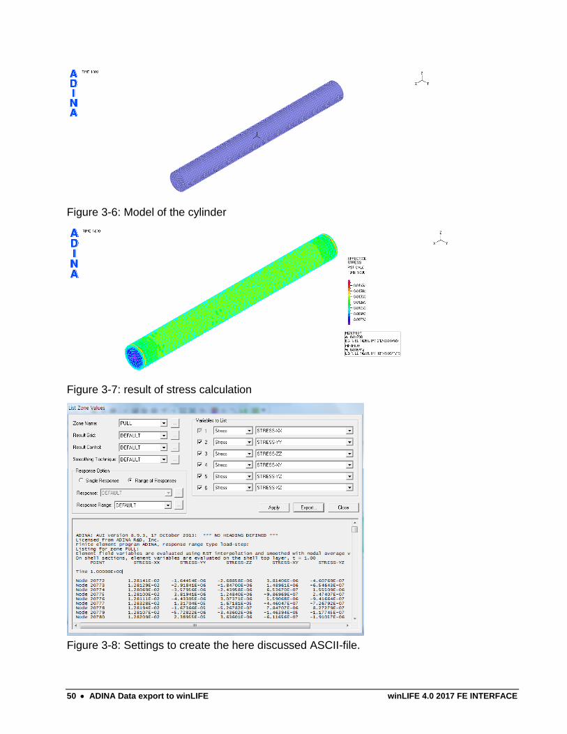
Figure 3-6: Model of the cylinder
Figure 3-7: result of stress calculation
Figure 3-8: Settings to create the here discussed ASCII-file.
winLIFE 4.0 2017 FE INTERFACE ADINA Data export to winLIFE 51
Figure 3-9: Result of the winLIFE fatigue calculation reimported to ADINA and shown there

winLIFE 4.0 2017 FE INTERFACE ABAQUS Data export to winLIFE 53
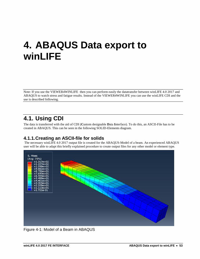
4. ABAQUS Data export to winLIFE
Note: If you use the VIEWER4WINLIFE then you can perform easily the datatransfer between winLIFE 4.0 2017 and
ABAQUS to watch stress and fatigue results. Instead of the VIEWER4WINLIFE you can use the winLIFE CDI and the
use is described following.
4.1. Using CDI The data is transferred with the aid of CDI (Custom designable Data Interface). To do this, an ASCII-File has to be
created in ABAQUS. This can be seen in the following SOLID-Elements diagram.
4.1.1. Creating an ASCII-file for solids The necessary winLIFE 4.0 2017 output file is created for the ABAQUS-Model of a beam. An experienced ABAQUS
user will be able to adapt this briefly explained procedure to create output files for any other model or element type.
Figure 4-1: Model of a Beam in ABAQUS
54 ABAQUS Data export to winLIFE winLIFE 4.0 2017 FE INTERFACE
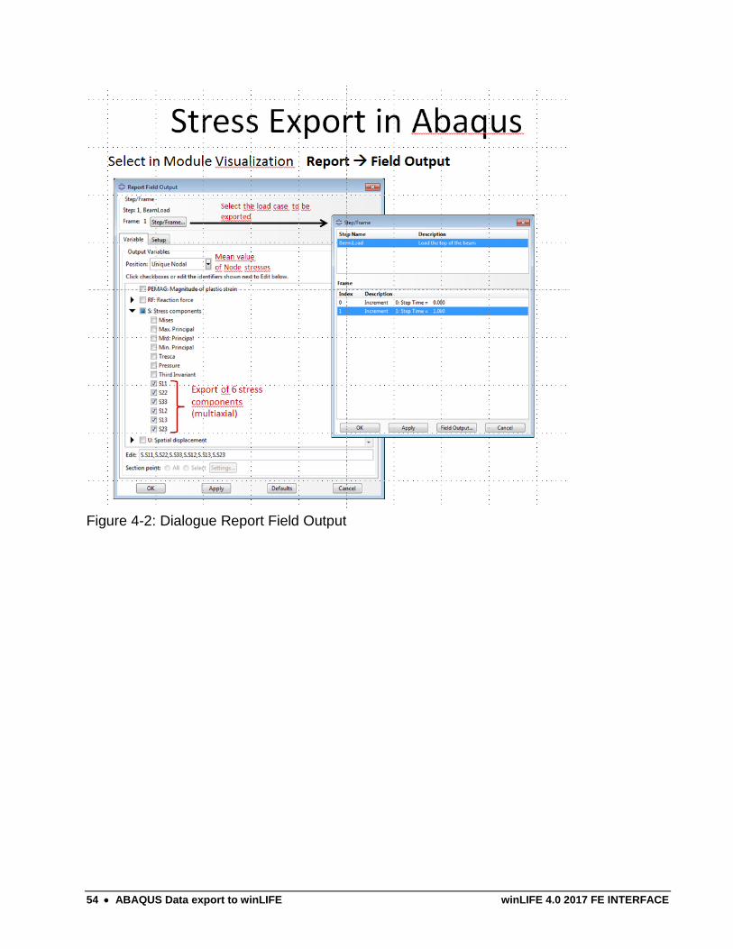
Figure 4-2: Dialogue Report Field Output
winLIFE 4.0 2017 FE INTERFACE ABAQUS Data export to winLIFE 55
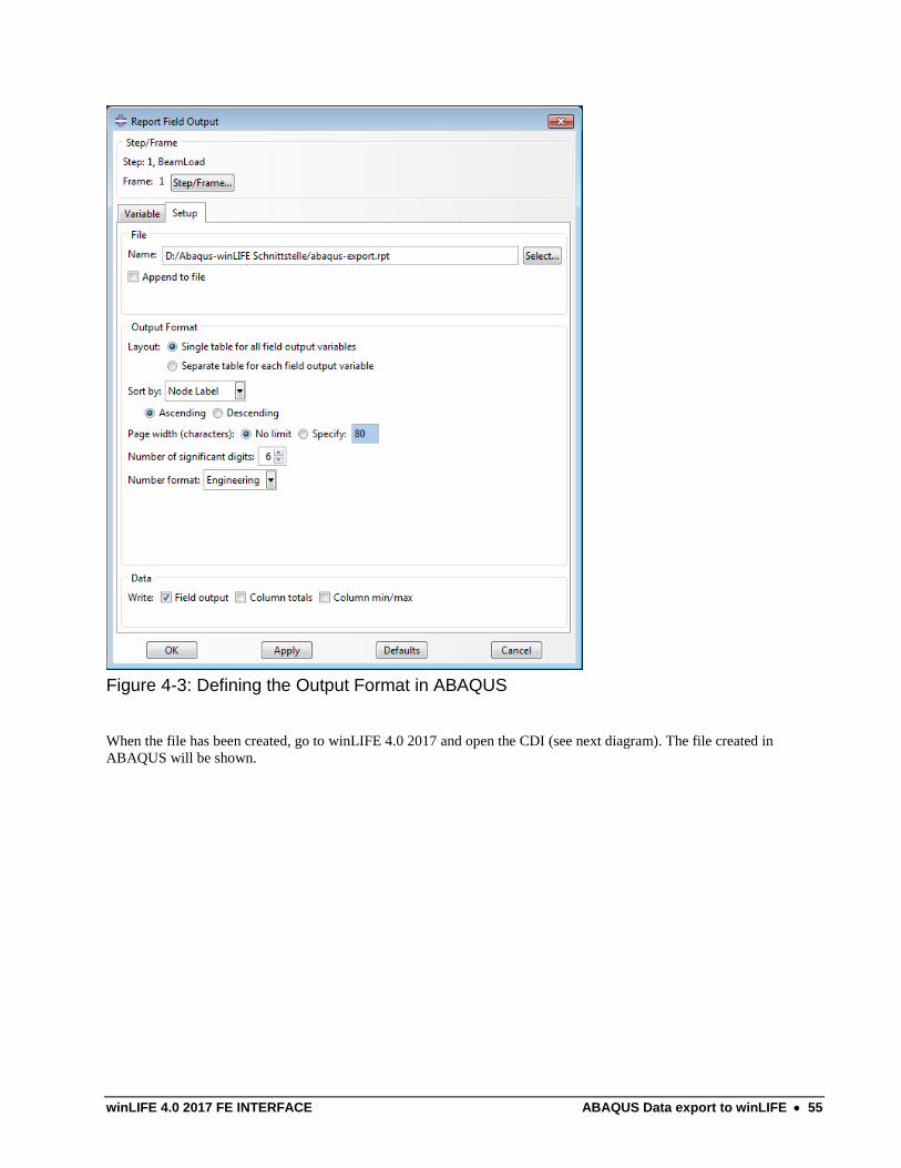
Figure 4-3: Defining the Output Format in ABAQUS
When the file has been created, go to winLIFE 4.0 2017 and open the CDI (see next diagram). The file created in
ABAQUS will be shown.
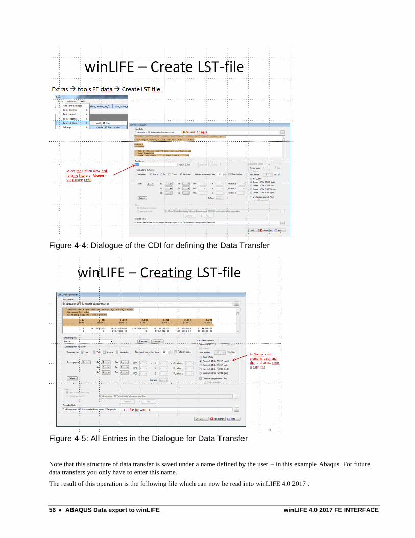
56 ABAQUS Data export to winLIFE winLIFE 4.0 2017 FE INTERFACE
Figure 4-4: Dialogue of the CDI for defining the Data Transfer
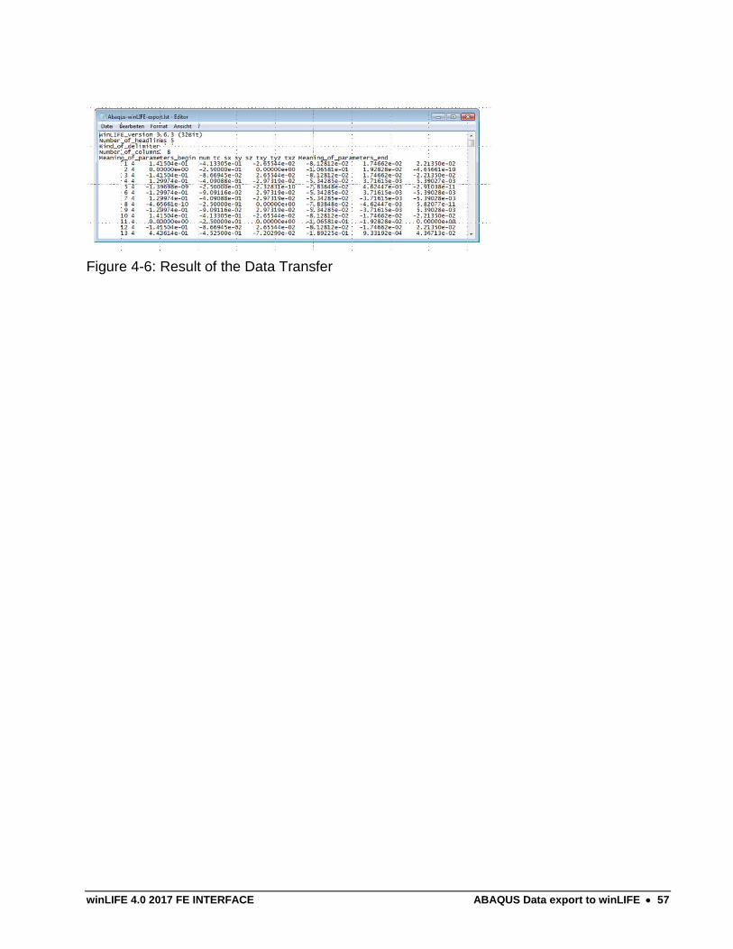
Figure 4-5: All Entries in the Dialogue for Data Transfer
Note that this structure of data transfer is saved under a name defined by the user – in this example Abaqus. For future
data transfers you only have to enter this name.
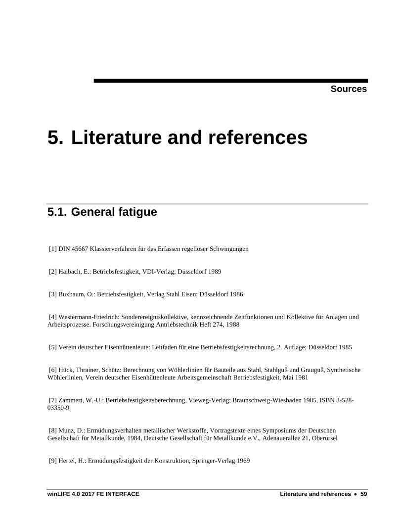
The result of this operation is the following file which can now be read into winLIFE 4.0 2017 .
winLIFE 4.0 2017 FE INTERFACE ABAQUS Data export to winLIFE 57
Figure 4-6: Result of the Data Transfer

winLIFE 4.0 2017 FE INTERFACE Literature and references 59
Sources
5. Literature and references
5.1. General fatigue
[1] DIN 45667 Klassierverfahren für das Erfassen regelloser Schwingungen
[2] Haibach, E.: Betriebsfestigkeit, VDI-Verlag; Düsseldorf 1989
[3] Buxbaum, O.: Betriebsfestigkeit, Verlag Stahl Eisen; Düsseldorf 1986
[4] Westermann-Friedrich: Sonderereigniskollektive, kennzeichnende Zeitfunktionen und Kollektive für Anlagen und
Arbeitsprozesse. Forschungsvereinigung Antriebstechnik Heft 274, 1988
[5] Verein deutscher Eisenhüttenleute: Leitfaden für eine Betriebsfestigkeitsrechnung, 2. Auflage; Düsseldorf 1985
[6] Hück, Thrainer, Schütz: Berechnung von Wöhlerlinien für Bauteile aus Stahl, Stahlguß und Grauguß, Synthetische
Wöhlerlinien, Verein deutscher Eisenhüttenleute Arbeitsgemeinschaft Betriebsfestigkeit, Mai 1981
[7] Zammert, W.-U.: Betriebsfestigkeitsberechnung, Vieweg-Verlag; Braunschweig-Wiesbaden 1985, ISBN 3-528-
03350-9
[8] Munz, D.: Ermüdungsverhalten metallischer Werkstoffe, Vortragstexte eines Symposiums der Deutschen
Gesellschaft für Metallkunde, 1984, Deutsche Gesellschaft für Metallkunde e.V., Adenauerallee 21, Oberursel
[9] Hertel, H.: Ermüdungsfestigkeit der Konstruktion, Springer-Verlag 1969
60 Literature and references winLIFE 4.0 2017 FE INTERFACE
[10] Gumpert, W.: Höhere Festigkeitslehre, Betriebsfestigkeit, 3. Lehrbrief; Lehrbriefe für das Hochschulfernstudium
Nr.: 02 1205 03 0; Herausgeber: Zentralstelle für das Hochschulfernstudium Dresden
[11] Heuler, P.: Anrißlebensdauer bei zufallsartiger Belastung auf der Grundlage örtlicher Beanspruchungen; Institut für
Stahlbau und Werkstoffmechanik der TH Darmstadt, Heft 40, 1983
[12] Bergmann, J.: Zur Betriebsfestigkeit gekerbter Bauteile auf der Grundlage der örtlichen Beanspruchungen;
Dissertation TH-Darmstadt 1983
[13] Krüger, Petersen: Simulation und Extrapolation von Rainflow-Matrizen; Bericht Nr. 8 der Arbeitsgruppe
Technomathematik des Fachbereichs Mathematik der Universität Kaiserslautern, Mai 1988
[14] Chlormann, U. H., Seeger, T: Rainflow-HCM - Ein Zählverfahren für Betriebsfestigkeitsnachweise auf
werkstoffmechanischer Grundlage. Stahlbau, 55[3], S. 65 - 71, 1986
[15] Masing, G.: Eigenspannung und Verfestigung beim Messing. In: Proc. of the 2nd
Int. Congress of Applied
Mechanics, S. 332-335, 1926
[16] Smith, K. N., Watson, P., Topper, T. H.: A Stress-Strain Function for the Fatigue of Metals. Journal of Materials, 5
[4], S. 767 - 768, 1970
[17] Boller, Chr., Seeger, T.: Materials Data for Cyclic Loading, Part A: Unalloyed Steels, Elsevier Science Publishers
B.V.1987, ISBN 0-444-42870-4
[18] Schön, M., Seeger, T.: Lebensdauerberechnung auf der Basic der Rainflow-Matrix, Technische Hochschule
Darmstadt, Fachgebiet Werkstoffmechanik, Vortrag im Haus der Technik 1993
[19] Radaj, D.: Ermüdungsfestigkeit, Springer-Verlag Berlin Heidelberg New York, ISBN 3-540-58348-3
[20] Haibach, E.: Betriebsfeste Bauteile, Konstruktionsbücher Band 38, Springer-Verlag Berlin Heidelberg New York,
ISBN 3-540-54815-7
[21] Boller, Chr., Seeger, T.: Materials Data for Cyclic Loading, Part B: Low Alloy Steels, Elsevier Science Publishers
B.V.1987, ISBN 0-444-42871-2
[22] Boller, Chr., Seeger, T.: Materials Data for Cyclic Loading, Part C: High Alloy Steels, Elsevier Science Publishers
B.V.1987, ISBN 0-444-42871-0
[23] Boller, Chr., Seeger, T.: Materials Data for Cyclic Loading, Part D:\\WINLITEX\\ENGLISCH Aluminium and
Titanium Alloys, Elsevier Science Publishers B.V.1987, ISBN 0-444-42873-9
[24] Boller, Chr., Seeger, T.: Materials Data for Cyclic Loading, Part E: Cast and Welded Metals, Elsevier Science
Publishers B.V.1987, ISBN 0-444-42874-7
winLIFE 4.0 2017 FE INTERFACE Literature and references 61
[25] Boller, Chr., Seeger, T.: Materials Data for Cyclic Loading, Part E: Unalloyed Steels, Elsevier Science Publishers
B.V.1987, ISBN 0-444-42874-7
[26] Issler, L., Ruoß, H., Häfele, P.: Festigkeitslehre Grundlagen, Springer-Verlag Berlin 1995, ISBN 3-540-57995-8
[27] Haibach, E., Berger, C., Hänel, B., Wirthgen, G., Zenner, H., Seeger, T.: Rechnerischer Festigkeitsnachweis für
Maschinenbauteile, Heft Nr. 183-1, 1994, Forschungskuratorium Maschinenbau, Lyonerstr. 18, Frankfurt/M.
[28] Dorn, S.: Rechnerische Lebensdauerermittlung nach verschiedenen Rechenkonzepten im Vergleich mit Meßdaten
und Bestimmung von Formzahlen mit Hilfe von FE-Rechnungen, Diplomarbeit an der FH-Coburg im
Studienschwerpunkt Maschinenbau, April 1996
[29] Zenner H. und Liu J.: Vorschlag zur Verbesserung der Lebensdauerabschätzung nach dem Nennspannungskonzept,
Konstruktion 44 [1992] Seite 9-17
[30] Bäumel A. ; Seeger, T.: Materials Data for Cyclic Loading, supplement 1, Elsevier Science Publishers B.V.1987,
ISBN 0-444-88603 6
[31] Manson S.S.: Fatigue: A Complex Subject - Some Simple Approximations. Experimental Mechanics, 5:193-226,
1965
[32] Muralidharan, U; Manson, S.S.: A Modified Universal Slopes Equation for Estimation of Fatigue Characteristics of
Metals. Journal of Engineering Materials and Technology, 110:55-58, 1988
[33] Gudehus, Zenner: Leitfaden für eine Betriebsfestigkeitsrechnung, Empfehlung zur Lebensdauerabschätzung von
Maschinebauteilen. 3. Auflage, ISBN 3-514-00445-5, Verlag Stahleisen, Düsseldorf.
[34] Störzel, K.; Sonsino C.M.: Verfahren zur Lebensdauerabschätzung auf der Basic von Rainflow-Matrizen
örtlicher Dehnungen; Fraunhofer - Institut für Betriebsfestigkeit [LBF], Darmstadt, LBF-Nr. 7662 [1994],
unveröffentlichter Eigenforschungsbericht.
[35] FKM Richtlinie: Rechnerischer Festigkeitsnachweis für Maschinenbauteile, 4. erweiterte Ausgabe 2002,
Forschungskuratorium Maschinenbau, 1998
[36] Häckh, J; Willmerding, G; Kley, M; Binz, H; Körner, T.: rechnerische Lebensdauerabschätzung von
Getriebegehäusen unter Einbeziehung relaer multiaxialer Belastungen, DVM-Tagung Fulda vom 5. bis 6.6. 2002, VDI-
Berichte N2. 1689, 2002 Seite 303 - 317
[37] Körner, T; Depping, H; Häckh, J; Willmerding, G; Klos, W.: Rechenrische Lebensdauerabschätzung unter
Berücksichtigung realer Belastungskollektive für die Hauptwelle eines Nutzfahrzeuggetriebes, DVM-Tagung Fulda vom
5. bis 6.6. 2002, VDI-Berichte N2. 1689, 2002 Seite 275 - 285
[38] Körner, T; Depping, H; Häckh, J; Willmerding, G.: Fatigue Life Prognosis for Transmissions based on critical
Component Spectrum, World Automotive Congress FISITA 2002, Helsinki, Paper Nr. F02V091
62 Literature and references winLIFE 4.0 2017 FE INTERFACE
[39] Eichsleder W. Unger B.: Lebensdauerberechnung auf der Basis von Finite Element Ergebnissen; 19.
Vortragsveranstaltung des DVM Arbeitskreises Betriebsfestigkeit München 1993
[40] Köttgen V.B.; Anthes R.J.; Seeger T.: Implementation des Werkstoffmodells von Mroz in das Finite Element
Programm Abaqus Teil 1; Bericht aus dem Fachgebiet Werkstoffmechanik der Universität Darmstadt
[41] Köttgen V.B.; Anthes R.J; Seeger T.: Implementation des Werkstoffmodells von Mroz in das Finite Element
Programm Abaqus Teil 2: Quelltext und Beispiele; Bericht aus dem Fachgebiet Werkstoffmechanik der Universität
Darmstadt
[42, ] Chu Chin-Chan; Conle F; Albrecht Bonnen; John J. F.: Multiaxial Stress-Strain Modeling and Fatigue Life
Prediction of SAE Axle Shafts; American Society for Testing and Materials, Philadelphia 1993
[43, ] Mayer, Kötzle: Lebensdauerabschätzung von Fahrwerksteilen unter Berücksichtigung der sich drehenden
Hauptspannungen; VDI-Berichte 1283, 1996 Seite 349
[44] Steinwender, Greald; Gaier, Christian; Unger, Bernhard: Simulationder Betriebsfestigkeit von mehrachsig
belasteten Fahrwerksbauteilen; 7. Aachener Kolloquium vom 5.-7. Oktober 1998, Aachen, Seite 1141
[45] Issler, Ruoß, Häfele: Festigkeitslehre Grundlagen
[46] Yousefi F.; Küppers, M.: Lebensdauerberechnung mehraxial, Vorhaben Nr. 235, Forschungskuratorium
Maschinenbau
[47] Radaj, D.; Sonsiono, C.M.;Fricke, W.: Fatigue assessment of welded joints by local approaches, 2. Auflage,
Woodhead publishing limited, ISBN-13: 978-1-85573-948-2
[48] Fricke, W.: Recommended hot spot analysis procedure for structural details of ships and FPSOs based on round-
robin FE analyses, Int J Offshore Polar Engng, 20020 12 [1], 40-47
[49] Bäckström, M.; Marquis, G.: A review of multiaxial fatigue of weldments: experimental results, design code and
critical plane approaches, Fatigue Fracture Egnng Mater Struct 24, 279-291
[50] Hobbacher, A.: Recommendations for fatigue design of welded joints and components, Inernational Institute of
welding, IIW document IIW-1823-07 december 2008
[51] Germanischer Lloyd: Guideline for the Certification of Offshore Wind Turbines, Edition 2005
[52] Gaier, C; Dannbauer, H.: An efficient critical plane method for ductile, semiductile and brittle materials, Fatigue
2006: 9th
International Fatigue Congress Atlanta, 14.5-19.5.2006, Vortrag Nr. FT 436
winLIFE 4.0 2017 FE INTERFACE Literature and references 63
[53] N.N.:Qualitätsmanagement in der Automobilindustrie; Zuverlässigkeitssicherung bei Automobilherstellern und
Lieferanten; Teil 2;.
ISSN 0943-9412, VDA, Frankfurt am Main, 2000
[54] Richard, H. A.; Sander, M.: Ermüdungsrisse, ISBN 978-3-8348-0292-7
[55] Rennert, R; Kullig, E; Vormwald, M; Esderts, A; Siegele, D: Rechnerischer Festigkeitsnachweis für
Maschinenbauteile; 6. Auflage 2012; ISBN 978-3-8163-0605-4
[56] Berger, C; Blauel. G; Hodulak, L; Pyttel, B; Varfolomeyev, I; Gerdes, C.P.: Bruchmechansciher
Festigkeitsnachweis für Maschinenbauteile; 3. Ausgabe, Stand 2009, ISBN 978-3-8163-0514-9
5.2. Gearwheel and Bearing
[1] DIN 3990 Teil 1: Tragfähigkeitsberechnung von Stirnrädern: Einführung und allgemeine Einflußfaktoren
[2] DIN 3990 Teil 2: Tragfähigkeitsberechnung von Stirnrädern: Berechnung der Grübchentragfähigkeit
[3] DIN 3990 Teil 2: Tragfähigkeitsberechnung von Stirnrädern: Dauerfestigkeit und Werkstoffqualitäten
[4] Forschungsvereinigung Antriebstechnik E.V.: Zahnfuß-Betriebsfestigkeit, Forschungsvorhaben Nr. 188/I und II,
1993 Heft 408 und 1996 Heft 502
[5] Forschungsvereinigung Antriebstechnik E.V.: Zahnflankenlebensdauer, Forschungsvorhaben Nr. 125/III, 1995 Heft
457
[5] Forschungsvereinigung Antriebstechnik E.V.: Zahnflankenlebensdauer, Forschungsvorhaben Nr. 125/III, 1995 Heft
457
[6] Forschungsvereinigung Antriebstechnik E.V.: Zahnrad-Lebensdauerprüfung mit Lastkollektiven,
Forschungsvorhaben Nr. 125/I Heft 290 1989
[7] Forschungsvereinigung Antriebstechnik E.V.: Zahnrad-Lebensdauerprüfung: Betriebsfestigkeitsuntersuchungen zur
Grübchenbildung an einsatzgehärteten Stirnradflanken, Heft 320 1991
[7] Forschungsvereinigung Antriebstechnik E.V.: Zahnrad-Lebensdauerprüfung: Betriebsfestigkeitsuntersuchungen zur
Grübchenbildung an einsatzgehärteten Stirnradflanken, Heft 320 1991
[8] G. Niemann; H. Winter: Maschinenelemente Band II; Getrieb3e allgemein, Zahnradgetriebe-Grundlagen,
Stirnradgetriebe, Zweite Auflage, Springer-Verlag, ISBN 3-540-11149-2
[9] Hexagon, Ein Programm zur Zahnradberechnung
64 Literature and references winLIFE 4.0 2017 FE INTERFACE
Statistics
[1] Gramlich, Günter.:
Skript zur Stochastik, Eine Einführung in die Mathematik der Daten des Zufalls, www.hs-ulm.de/gramlich
[2] Kleppmann, Wilhelm:
Taschenbuch Versuchsplanung, Hanser-Verlag, 2009, ISBN 978-3-446-420335-5
[3] wikipedia:
http://en.wikipedia.org/wiki/Latin_square
[4] M.D. McKay ; R. J. Beckmann ; W.J. Conover:
A comparison of three methods for selecting values of input variables in the analysis of output from a computer code,
Zeitschrift Technometrics, Vol. 21, No, 2, May 1979
[5] Aleksandar Trifkovi:
Multi-objective and Risk-based Modelling Methodology for Planning, Design and Operation of Water Supply Systems,
Dissertation Universität Stuttgart, Institut für Wasserbau, 2007
[6] Haibach: Betriebsfestigkeit, VDI-Verlag
[7] Willmerding, G.:
Opti: ein Programm zur Multiplen, nichtlinearen Regressionsanalyse. Handbuch zur Software. Steinbeis TZ-
Verkehrstechnik 1986
winLIFE 4.0 2017 FE INTERFACE Legal Liability 65
Conditions of use
6. Legal Liability
6.1. § 1 Subject of this Agreement
1.1 The buyer purchases the winLIFE Software from
Steinbeis GmbH & Co. KG for Technology Transfer
Represented by
Steinbeis Transfer Centre
New Technologies in Traffic Engineering
Prittwitzstrasse 10, 89075 Ulm, Germany
- hereinafter referred to as the “seller” -
under the terms of use agreed to in this contract.
1.2 The source code for the software is not part of the subject of this agreement.
1.3 The nature of the software delivered by the seller is subject to the service description valid at the time of the
software being despatched and which was available to the buyer at the time of the contract being finalised. The service
provided by the seller is not expected to exceed this.
1.4 The general business terms & conditions of the buyer are not a subject of this contract, not even when an offer
request, order or declaration of acceptance is attached and/or not contradicted.
6.2. § 2 Conditions of Use 2.1 Once the buyer has paid the total amount, the seller grants him use of the winLIFE software. The conditions of
use are for a single licence, valid for an unlimited length of time, and not sub-licensable.
66 Legal Liability winLIFE 4.0 2017 FE INTERFACE
2.2 The buyer may only use the winLIFE software for internal business purposes or for other companies within the
same concern, according to paragraph 15 of the AktG. Commercial sub-leasing of the software is not permitted.
2.3 The buyer is only permitted to copy the winLIFE software if this is necessary for use according to the contract.
The buyer may make safety backup copies of the winLIFE software as necessary according to technical standards.
Backup copies on mobile data storage media must be labelled as such and endorsed with the copyright of the original
data storage medium.
2.4 The buyer is only permitted to make changes, extensions and other alterations to the winLIFE software as
allowed by law according to paragraph 69c No.2 of the UrhG. The buyer is not permitted to execute his own rights and
conditions of use other than stated in this contract.
2.6 Should the seller permit the buyer to make improvements or carry out maintenance on alterations (eg patches,
alterations in the user instructions) or create a new version of the winLIFE software (eg update, upgrade, new user
instructions) which replace former objects of the contract, then these alterations or new versions will also be subject to
the rules of this contract.
2.7 If the seller produces a new version of the winLIFE Software then the seller’s authorisation regarding the old
winLIFE software in this contract becomes invalid as soon as the buyer uses the new winLIFE software. This is the case
even when the seller does not explicitly demand the return of the old software. However, the seller allows the buyer a
changeover period of three months in which both versions of the software can be used simultaneously.
6.3. § 3 Sales Price, Terms of Payment 3.1 The buyer purchases the rights of use as stated in the offer for the sales price also stated in the offer. The sales
price complies with the offer on which this software sales contract is based. The buyer is only permitted to use the
software according to the rights of use stated in this contract. Any other use requires prior consent in writing from the
seller. In the case of multiple use without consent (in particular when the software is used simultaneously by a more
users than agreed to) the seller has the right to invoice the additional use according to the seller’s price list valid at that
particular time unless the buyer can prove a lower sum of damage. This does not have any effect on other non-
contractual compensation claims.
3.2 The sales price is due and must be paid in full when the software is delivered or provided.
3.3 In addition to the given price, VAT at the current rate must be paid.
3.4 The delivery prices include transport and packing for posted deliveries. For goods which are to be transferred on
the net, the seller bears the costs of making the software accessible; the buyer bears the costs of the retrieval.
3.5 The ownership of surrendered copies remains subject to alteration until the payment has been made in full.
6.4. § 4 Installation, Training, Maintenance 4.1 When installing the winLIFE software, please read the installation notes included in the user documentation, in
particular those regarding the hardware and software environment needed by the buyer. By installing the program onto
his computer, the buyer commits himself to the terms of this contract. If the buyer does not agree to the terms, then the
CDs and all other documentation is to be returned immediately. The purchase price will then be reimbursed from where
it was purchased.
winLIFE 4.0 2017 FE INTERFACE Legal Liability 67
4.2 At the buyer’s request the seller will assume the training and maintenance of the winLIFE software based on a
separate contractual agreement and applicable price list. The seller is prepared to maintain the software based on the
terms of a separate maintenance contract
6.5. § 5 Protection of Software and user documentation 5.1 Unless the buyer is granted specific rights within this contract then all rights regarding the winLIFE software
(and all copies made by the buyer) – in particular the copyright, the patent rights and the technical protection rights –
apply to the seller.
6.6. § 6 Transfer 6.1 The buyer is only permitted to pass the winLIFE software on to a third party provided he transfers the total
product and renounces his own use of the software completely and finally.
6.2 A temporary transfer of the winLIFE software to a third party is not permitted either as a hard copy or
otherwise.
6.3 If the buyer passes on data storage media, memory or other hardware on which objects of the contract (complete
or partial, altered or edited) have been saved,
6.3.1 to third parties without being subject to a transfer according to paragraph 6 or
6.3.2 renounces his direct ownership hereof
then he carries the responsibility that the winLIFE software is completely deleted.
6.7. § 7 User Cooperation and Information Obligations 7.1 The buyer has informed himself of the essential function characteristics of the winLIFE software and carries
the risk whether these are in accordance with his needs and wishes. If there is any doubt he should obtain qualified
information from the seller.
7.2 It is the sole responsibility of the buyer to ensure that he has a working and – bearing in mind the additional
storage requirements of the winLIFE software - sufficiently dimensioned hardware and software environment.
7.3 Before using it, the buyer is to test the winLIFE software extensively for its usage in the existing hardware and
software configuration. This is also the case for software acquired within the framework of the guarantee.
7.4 The buyer is to make sufficient provisions for the case that the winLIFE software does not work properly,
either wholly or partially (for example by making daily backups, error diagnoses, regular controls of the data results).
6.8. § 8 Time of Delivery and Performance, Acts of God 8.1 Unless otherwise agreed upon, the current version of the software will be delivered.
8.2 The seller delivers the goods according to his choice as follows:
8.2.1 He provides the buyer with (1) a copy of the software program on a computer-legible data storage medium,
together with user documentation for each user according to section 2.1.

68 Legal Liability winLIFE 4.0 2017 FE INTERFACE
8.2.2 He makes the software available in a network where it can be retrieved and informs the buyer accordingly and
provides user documentation for each user according to section 2.1.
8.3 The time of delivery and the passing of risk for material despatch are considered to be the time when the seller
hands over the software and user documentation to the transport company. Otherwise it is the time when the software is
made available in a network where it can be retrieved and the buyer is informed accordingly.
8.4 As long as the seller
8.4.1 is still waiting for cooperation or information from the buyer or
8.4.2 is delayed in his performance due to strikes or lock-outs in third-party companies or in the seller’s company (in
the latter case, however, only if the industrial action is legal), intervention through the authorities, legal bans or other
circumstances that are no fault of his own (act of God).
then the times of delivery and performance are considered extended for the length of the hindrance (“time of non-use”)
and no breach of duty is regarded for the time of non-use. The seller is to immediately inform the buyer of such
hindrances and their anticipated length. If an “act of God” continues continually for longer than three months then both
parties are freed of their delivery duties.
6.9. § 9 Material and Warranty Defects, other Performance Failures, Statute of Limitations
9.1 The seller is liable for any material and warranty defects of the subject of agreement as in section 1.3 according
to the terms and conditions of sale and for the fact that the buyer does not conflict the rights of third parties regarding the
use of the subject of agreement to the extent of the contract.
The liability for the freedom of the subject of agreement by rightful third parties is, however, only valid for the country
in which the subject of agreement is to be used, as agreed upon by the parties. Unless otherwise agreed upon, the country
of liability is The Federal Republic of Germany.
9.2 In the case of material defect, the seller firstly provides supplementary performance. As decided by the seller,
the buyer either receives new faultless software or the defect is corrected. A valid method of correction is also if the
seller shows the buyer a reasonable possibility of correcting the failure.
In the case of legal defects the seller firstly provides supplementary performance. As decided by the seller, the buyer
either receives a legally faultless possibility of use for the delivered subject of agreement or replaces it with an
exchanged or altered subject of agreement of the same value.
9.3 The buyer is obliged to accept new software as long as its function remains the same and its acceptance does not
lead to any considerable disadvantage.
9.4 If two attempts to provide supplementary performance fail, then the buyer is entitled to insist on an acceptable
date for removal of defects. In doing so he must clearly and in writing state that he has the right, should the
supplementary performance again be unsuccessful, to withdraw from the contract and/or demand compensation.
If the error cannot be corrected even in the period of grace, the buyer can withdraw from the contract or reduce the
payment unless the failure is a “petit” failure. The seller is liable for compensation or replacement of correction measures
carried out in vain within the limits stated in section 10.
9.5 If there are claims made by third parties which deter the buyer from assuming his rights of use as stated in the
contract then the buyer is to inform the seller immediately and completely in writing. Herewith he authorises the buyer to
dispute the matter with the third party either in court or out of court.
winLIFE 4.0 2017 FE INTERFACE Legal Liability 69
The seller is obliged to defend the claims at his own cost and to release the buyer from all costs and damages relating to
the defence of the claims as long as these are not caused by his lack of duty.
9.6 The limitation period for all guarantee claims is one year beginning with the delivery or moment when the
subject of agreement is made available. The same period is valid for other claims, of whatever manner, against the seller.
9.7 In the case of malice intent or gross negligence on the part of the seller, or in the case of fraudulent concealment
regarding a fault, in cases of personal injury or legal faults as in § 438 Abs. 1 a BGB, and in guarantees (§ 444 BGB) the
legal limitation period is valid. This also applies for claims according to the Product Liability Law.
6.10. § 10 Reliability 10.1 For all cases of contractual and ex-contractual reliability, the seller provides compensation only within the
following limits:
10.1.1 In cases of intent totally, also if there are errors in the configuration guaranteed by the seller.
10.1.2 in cases of negligence only for the amount of the foreseeable damage caused by the negligence.
10.1.3 in other cases only to the extent of the typically foreseeable damage. If the typically foreseeable damage is
higher than the purchase price of the winLIFE software for one damage case, then the buyer is obliged to inform the
seller within 2 weeks of finalising the contract. In this case the seller has the right to withdraw from the contract unless a
liability limit has otherwise been agreed to.
10.2 The liability limitation according to paragraph 10.1 does not apply to the liability for personal damage and for
the liability according to the product liability law.
10.3 The seller is at liberty to raise objection to the contributory negligence (e.g. as in paragraph 7).
10.4 The statute of limitations is according to paragraph 9.6. The legal statutes of limitations apply to claims
according to paragraphs 10.1.1 and 10.2. The statute of limitations for Part 1 begins at the time stated in paragraph 199
No.1 of the BGB. This comes into account at the latest at the event of the statutory period stated in paragraph 199 Nos.3
and 4 of the BGB.
10.5 As long as the liability according to these terms is excluded or limited, then this also applies for the personal
liability of the organisation, the staff, representatives and sub-agents of the seller.
6.11. § 11 Secrecy, Data Protection 11.1 The parties of the contract are obliged to treat all the other party’s confidential information and company trade
secrets which come to knowledge during the initiation and implementation of the contract confidentially for an unlimited
period of time. These are only to be used for the implementation of this contract. The subject(s) of agreement and the
performance agreed to in the contract are also matters which are included in the seller’s company trade secrets.
11.2 The buyer may only allow staff and other third parties access to the subject of agreement as long as this is
necessary for the execution of the authorisation of use agreed to.
11.3 The above mentioned obligations are not valid for company trade secrets which
11.3.1 were already obvious or known to the other party at the time of conveyance.
70 Legal Liability winLIFE 4.0 2017 FE INTERFACE
11.3.2 became obvious after the time of conveyance through the contractual partner through no fault of the other
contractual party.
11.3.3 became known to the other contractual party after conveyance by the contractual partner by a third person in a
manner which is not illegal and without limitation in regard to secrecy or usage.
11.3.4 which have been developed by one of the contractual partners independently without using the trade secrets of
the contractual partner.
11.3.5 which must be made public according to the law, authoritative decision or court order – providing the party
releasing the information informs the contractual partner hereof immediately and supports him in the defence of such
decisions or orders; or
11.3.6 as long as the contractual partner is permitted to use or pass on the trade secret due to urgent legal conditions or
as a result of this contract.
11.4 The seller is to adhere to the rules of data protection, in particular when he is granted access to the buyer’s
company or to his hardware/software
6.12. § 12 Final Clause 12.1 Exclusive Place of Jurisdiction for all disputes relating to or resulting from this contract is the seller’s business
location. If the seller has a claim, he is also entitled to choose the Place of Jurisdiction and the buyer’s business location.
The right for both parties to apply for preliminary injunction legal protection from a court legally responsible remains
untouched.
12.2 Only German law applies excluding UN-purchase laws (CISG).
12.3 The completion of the contract as well as any later alterations and additions must be in writing to be effective.
That is also the case for changing this clause. It does not apply to verbal subsidiary agreements. All declarations by the
parties are to be in writing.
12.4 Should a condition of this contract be or become invalid, or if there is an invalid time period or a gap, then the
legality of the other conditions remains untouched hereby. As long as the invalidity does not violate §§ 305ff. BGB
(Validity of General Business Terms and Conditions) then instead of the invalid condition, a valid condition is agreed to
which is nearest to that intended by the parties in a commercial sense. The same applies in the case of a gap. In the case
of an unacceptable period, the legally acceptable period becomes valid. If there is a violation to §§ 305ff. BGB then the
parties shall find an amicable solution in terms of paragraph 2.
Index 71
7. Index
§
§ 1 Subject of this Agreement 65
§ 10 Reliability 69
§ 11 Secrecy, Data Protection 69
§ 12 Final Clause 70
§ 2 Conditions of Use 65
§ 3 Sales Price, Terms of Payment 66
§ 4 Installation, Training, Maintenance 66
§ 5 Protection of Software and user documentation 67
§ 6 Transfer 67
§ 7 User Cooperation and Information Obligations 67
§ 8 Time of Delivery and Performance, Acts of God 67
§ 9 Material and Warranty Defects, other Performance Failures, Statute of Limitations 68
A
ABAQUS Data export to winLIFE 53
ADINA Data export to winLIFE 47
C
Create Surface Group 21
Create Surface Plate and Group 21
Create Weld Groups 23
Creating an ASCII-file for plates 47
Creating an ASCII-file for solids 49, 53
D
Description of the winLIFE import file *.LST 36
E
Export node list 36
Export of stresses for the multiaxial case 27
Export of stresses for the uniaxial case 24
F
FEMAP Installation notes and Interface 19
File Summary (V4.0) 16
G
Gearwheel and Bearing 63
72 Index winLIFE 4.0 2017 FE INTERFACE
General fatigue 59
H
High-Speed interface (only in special cases) 20
I
Import the fatigue results from winLIFE into FEMAP 33
Improvements compared to Version V3.2 4
Installation 5
Interface for ANSYS 4
Interface winLIFE to ANSYS (V4.0) 4
L
Legal Liability 65
Literature and references 59
N
Named Selections 7
P
Preprocessing in ANSYS Workbench 6
Project Schematic Workflow 6
R
Runtime environment for the macros 4
S
Standard Interface (recommended) 20
Starting the Interface 7
T
The winLIFE Toolbar 8
U
Using CDI 47, 53
Using FEMAP 20
Using the original FEMAP commands 37
W
winLIFE EXPORT Toolbar - winLIFE_exp.abbr 8
winLIFE IMPORT Toolbar - winLIFE_imp.abbr 9
winLIFE MAIN Toolbar - winLIFE_main.abbr 8
winLIFE POST Toolbar - winLIFE_post.abbr 9
winLIFE to ANSYS Interface Macros 10
winlife.mac 10
wl_eskin.mac 11
wl_export.mac 13
wl_extrap.mac 13
wl_import.mac 14
wl_lstep.mac 13
wl_nskin.mac 10
Index 73
wl_param.mac 15
wl_post.mac 15
wl_rsys.mac 12
wl_setelem.mac 12
wl_settype.mac 11