Embed Size (px)
Citation preview
Designing Power-Friendly Devices
Barnes CooperJaya JeyaseelanPaul Diefenbaugh
Intel Corporation
May 8, 2007
AbstractThis paper focuses on a generally-observed industry problem, where the behavior of devices causes a significant increase to system power. Much work has been done in Microsoft® Windows® operating systems such as Windows XP and Windows Vista®, as well as in the hardware on modern processors, chipsets, and supporting logic to enable deep processor and platform power management. Unfortunately, today’s systems are not optimized for situations where devices may generate power-unfriendly traffic patterns or do not support (or do not properly implement) baseline mobile platform features such as link power management or intelligent traffic management.
The first section of this paper covers key concepts of modern-day multicore platform power management works, with real-world data to illustrate the power impact of ill-behaved devices on platforms.
The second section focuses on PCI Express Base Specification 2.0 (PCIe) and some of the key challenges observed. This includes suboptimal usage of low-power link states and how certain traffic patterns may defeat important platform power management techniques. Key recommendations for PCIe devices including link state support, local power management policy, and production of activity patterns that help facilitate good platform energy efficiency.
The third section focuses on USB 2.0. It begins with an overview of the software model, traffic classes, and interface speeds, and then dives into device behavioral issues and recommendations including dynamic asynchronous scheduler management, conveying interrupt information through periodic endpoints, and the proper use of selective suspend.
This information applies for the following operating systems:Windows Server® 2008Windows Vista®Microsoft Windows Server 2003Microsoft Windows XPMicrosoft Windows 2000

Designing Power-Friendly Devices - 2
ContentsIntroduction............................................................................................................................3
Responsiveness vs. Battery Life.........................................................................................4Energy-Efficient Device Recommendations........................................................................4
Understand the Platform Power Impact.........................................................................5Move Fine-Grain Control to the Device..........................................................................5Ensure Adequate Device Buffering................................................................................5Interrupt Response Latency Tolerance..........................................................................6
PCI Express.............................................................................................................................6Bus Traffic Alignment..........................................................................................................7Coalescing Interrupts..........................................................................................................8PCI Express Link Power Management...............................................................................9
Link Power Management Recommendations...............................................................10Link Exit Timings..........................................................................................................14L1 Policy Recommendations........................................................................................15
Universal Serial Bus 2.0 (USB 2.0)........................................................................................16USB 2.0 Full- and Low-Speed Data Patterns....................................................................17USB 2.0 High-Speed Data Patterns..................................................................................17Networking Device Recommendations.............................................................................20Streaming Device Recommendations...............................................................................22Human Interface Device Recommendations.....................................................................24Occasional Use Device Recommendations......................................................................24Implementation Details......................................................................................................25
Function Driver Interrupt Poll Bulk Read Method.........................................................25Submitting Bulk/Interrupt IN.........................................................................................26
Conclusion.............................................................................................................................26Call to Action..........................................................................................................................26
Author's Disclaimer and Copyright:
Copyright © 2007, Intel Corporation. All rights reserved.
Intel Core processor, Intel® Core™2 Duo processor are trademarks of Intel Corporation in the U.S. and other countries.
Actual measurement results may vary depending on the specific hardware and software configuration of the computer system measured, the characteristics of those computer components not under direct measurement, variation in processor manufacturing processes, the benchmark utilized, the specific ambient conditions under which the measurement is taken, and other factors.
LEGAL NOTICE
INFORMATION IN THIS DOCUMENT IS PROVIDED IN CONNECTION WITH INTEL® PRODUCTS. EXCEPT AS PROVIDED IN INTEL'S TERMS AND CONDITIONS OF SALE FOR SUCH PRODUCTS, INTEL ASSUMES NO LIABILITY WHATSOEVER, AND INTEL DISCLAIMS ANY EXPRESS OR IMPLIED WARRANTY RELATING TO SALE AND/OR USE OF INTEL PRODUCTS, INCLUDING LIABILITY OR WARRANTIES RELATING TO FITNESS FOR A PARTICULAR PURPOSE, MERCHANTABILITY, OR INFRINGEMENT OF ANY PATENT, COPYRIGHT, OR OTHER INTELLECTUAL PROPERTY RIGHT.
Windows Hardware Engineering Conference - WinHEC Sponsors’ Disclaimer: The contents of this document have not been authored or confirmed by Microsoft or the WinHEC conference co-sponsors (hereinafter “WinHEC Sponsors”). Accordingly, the information contained in this document does not necessarily represent the views of the WinHEC Sponsors and the WinHEC Sponsors cannot make any repaper concerning its accuracy. THE WinHEC SPONSORS MAKE NO WARRANTIES, EXPRESS OR IMPLIED, WITH RESPECT TO THIS INFORMATION.
Microsoft, Windows, Windows Server, and Windows Vista are either registered trademarks or trademarks of Microsoft Corporation in the United States and/or other countries. The names of actual companies and products mentioned herein may be the trademarks of their respective owners.
WinHEC 2007
Designing Power-Friendly Devices - 3
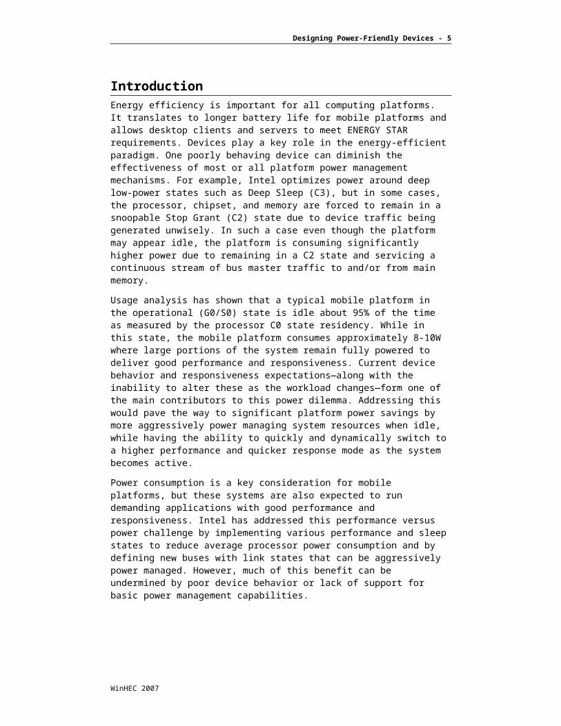
IntroductionEnergy efficiency is important for all computing platforms. It translates to longer battery life for mobile platforms and allows desktop clients and servers to meet ENERGY STAR requirements. Devices play a key role in the energy-efficient paradigm. One poorly behaving device can diminish the effectiveness of most or all platform power management mechanisms. For example, Intel optimizes power around deep low-power states such as Deep Sleep (C3), but in some cases, the processor, chipset, and memory are forced to remain in a snoopable Stop Grant (C2) state due to device traffic being generated unwisely. In such a case even though the platform may appear idle, the platform is consuming significantly higher power due to remaining in a C2 state and servicing a continuous stream of bus master traffic to and/or from main memory.
Usage analysis has shown that a typical mobile platform in the operational (G0/S0) state is idle about 95% of the time as measured by the processor C0 state residency. While in this state, the mobile platform consumes approximately 8-10W where large portions of the system remain fully powered to deliver good performance and responsiveness. Current device behavior and responsiveness expectations—along with the inability to alter these as the workload changes—form one of the main contributors to this power dilemma. Addressing this would pave the way to significant platform power savings by more aggressively power managing system resources when idle, while having the ability to quickly and dynamically switch to a higher performance and quicker response mode as the system becomes active.
Power consumption is a key consideration for mobile platforms, but these systems are also expected to run demanding applications with good performance and responsiveness. Intel has addressed this performance versus power challenge by implementing various performance and sleep states to reduce average processor power consumption and by defining new buses with link states that can be aggressively power managed. However, much of this benefit can be undermined by poor device behavior or lack of support for basic power management capabilities.
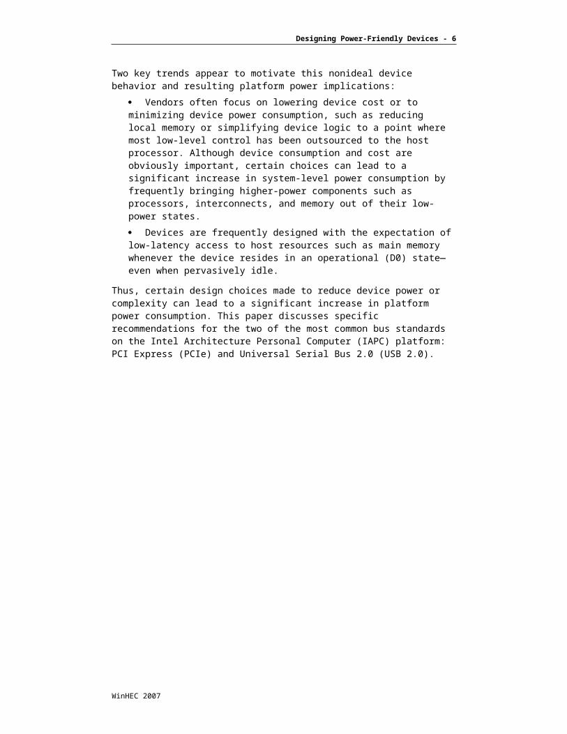
Two key trends appear to motivate this nonideal device behavior and resulting platform power implications:
Vendors often focus on lowering device cost or to minimizing device power consumption, such as reducing local memory or simplifying device logic to a point where most low-level control has been outsourced to the host processor. Although device consumption and cost are obviously important, certain choices can lead to a significant increase in system-level power consumption by frequently bringing higher-power components such as processors, interconnects, and memory out of their low-power states.
Devices are frequently designed with the expectation of low-latency access to host resources such as main memory whenever the device resides in an operational (D0) state—even when pervasively idle.
Thus, certain design choices made to reduce device power or complexity can lead to a significant increase in platform power consumption. This paper discusses specific recommendations for the two of the most common bus standards on the Intel Architecture Personal Computer (IAPC) platform: PCI Express (PCIe) and Universal Serial Bus 2.0 (USB 2.0).
WinHEC 2007

Designing Power-Friendly Devices - 4
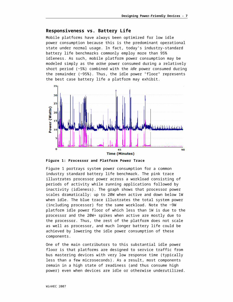
Responsiveness vs. Battery LifeMobile platforms have always been optimized for low idle power consumption because this is the predominant operational state under normal usage. In fact, today’s industry-standard battery life benchmarks commonly employ more than 95% idleness. As such, mobile platform power consumption may be modeled simply as the active power consumed during a relatively short period (~5%) combined with the idle power consumed during the remainder (~95%). Thus, the idle power "floor" represents the best case battery life a platform may exhibit.
Figure 1: Processor and Platform Power Trace
Figure 1 portrays system power consumption for a common industry standard battery life benchmark. The pink trace illustrates processor power across a workload consisting of periods of activity while running applications followed by inactivity (idleness). The graph shows that processor power scales dramatically: up to 20W when active and down below 1W when idle. The blue trace illustrates the total system power (including processor) for the same workload. Note the ~9W platform idle power floor of which less than 1W is due to the processor and the 20W+ spikes when active are mostly due to the processor. Thus, the rest of the platform does not scale as well as processor, and much longer battery life could be achieved by lowering the idle power consumption of these components.
One of the main contributors to this substantial idle power floor is that platforms are designed to service traffic from bus mastering devices with very low response time (typically less than a few microseconds). As a result, most components remain in a high state of readiness (and thus consume high power) even when devices are idle or otherwise underutilized. Instead of always expecting an immediate response from the platform, devices should be designed to tolerate longer response times when idle or when transitioning from an idle to active state.
Energy-Efficient Device RecommendationsThe next two sections present guidelines for improving the behavior of devices, with a focus on the PCI Express (PCIe) and Universal Serial Bus 2.0 (USB 2.0) standards. General considerations for designing energy-efficient devices are also discussed.
WinHEC 2007
Designing Power-Friendly Devices - 5
Understand the Platform Power ImpactThe first fundamental principle is to measure and analyze how specific device design decisions and behavior impact the power consumption of both the device and the rest of the platform. Various test platforms exist and can be used to measure power consumption of the entire platform as well as discrete components (such as processor, chipset, and memory). The device’s effect on platform power consumption should be observed across a variety of workloads, where minimal power should be consumed by the device and platform when idle.
As an example, consider a wireless device searching for wireless connections such as a Bluetooth client or wireless LAN access point. Care should be taken to perform these operations in an energy-efficient manner such as entirely device-based without host intervention or, if the host is required, periodically but infrequently.
Move Fine-Grain Control to the DeviceThe most energy-efficient approach for device design often involves using dedicated processing resources local to the device rather than offloading low-level maintenance and other device-specific operations to the host processor. The power differences between these two approaches can be dramatic.
In an effort to lower cost, many device implementations have eliminated embedded microcontrollers and other local resources and moved significant functionality to software—typically in the form of a device driver running on the host processor. This approach often mandates frequent, low-level intervention by the host that is far from energy efficient. In several cases, the relatively small cost savings achieved on the device are offset by an even higher increase in platform costs (such as larger batteries or more complex cooling).
Generally, all low-level functionality and fine-grain control should be located on the device where the bulk of device-to-host interaction is solely to move data. For instance, a wireless communications device should handle most wireless and network maintenance tasks independently, where host involvement occurs only when meaningful data has been received or must be transmitted. The device should also be capable of handling events with stringent timing requirements (on the order of tens of microseconds or less) whenever possible to relieve the host of hard real-time requirements.
Ensure Adequate Device BufferingMobile platforms with deep power management states have device-observable latencies to main memory that may be much higher than desktop or server platforms because features such as memory self-refresh, clock gating, and low-power link/bus states are employed at the platform level. Because the policies are typically based on heuristics and policy engines, the latencies observed by devices can also be highly variable.
As such, devices should be designed with adequate buffering to not trigger overrun/underrun conditions during various operational modes. As a general guideline, a device should have a minimum of 300 microseconds of data buffering to withstand the longer response time of mobile platform in low-power states and routine occurrences of bus pressure due to contention with other bus mastering devices.
WinHEC 2007
Designing Power-Friendly Devices - 6
Interrupt Response Latency ToleranceIn conjunction with adequate buffering, the device should not require fast response times for bus master or interrupt traffic under all conditions. During light load or semi-idle operation, the device should scale down its quality-of-service requirements and perhaps require tighter response times when the device is busy moving and processing data at relatively high-workload conditions.
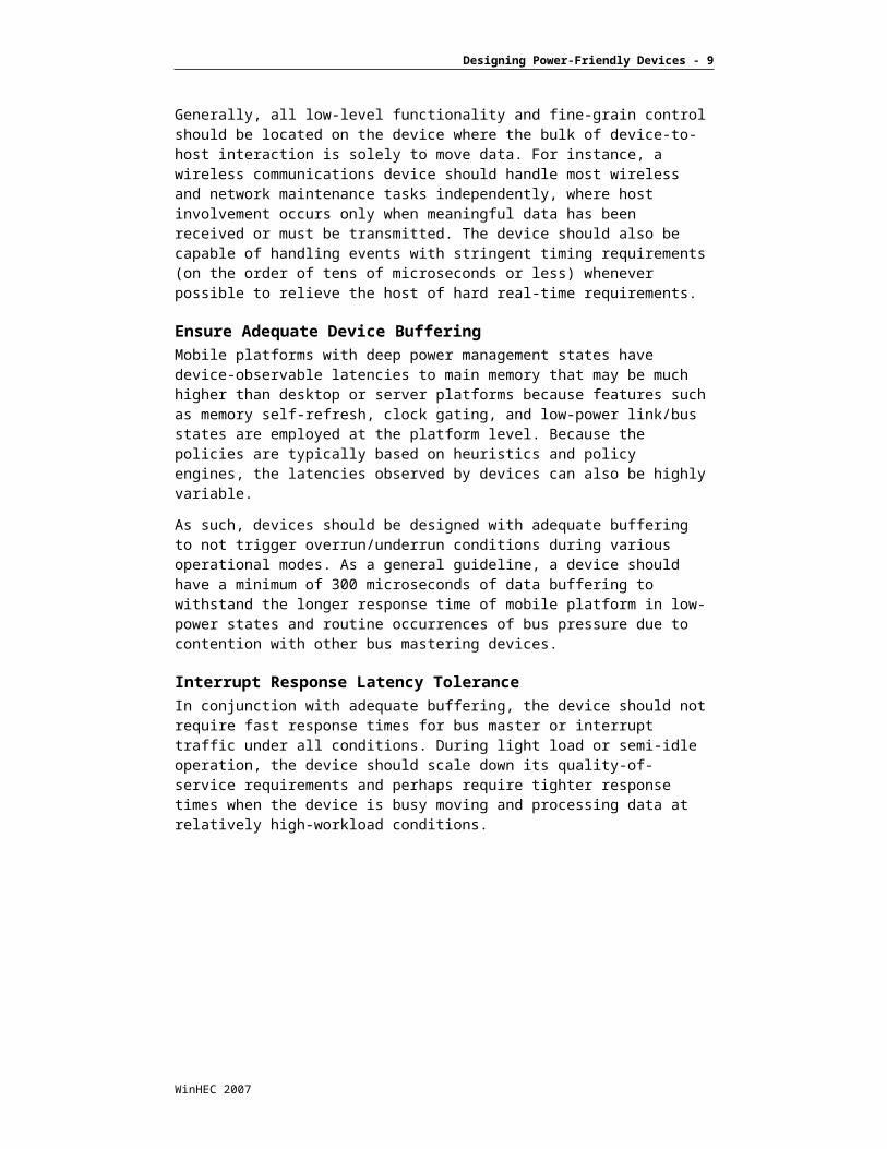
Software latencies for interrupt service routines and deferred procedure calls are unbounded, and although routinely rather small, can in some instances occasionally be deferred for periods of milliseconds due to natural infrequent alignment of random events. Figure 2 is a snapshot of interrupt and deferred procedure calls under Windows XP.
Int Ack To DPC Entry Latency
0
2
4
6
8
10
12
14
16
18
0 10 20 30 40 50 60 70 80 90 100 110 120 130 140 150
Microseconds
Fre
qu
ency
Frequency
Figure 2: Platform Interrupt Latency Histogram
Although typical latencies may be low, occasional excursions may be an order of magnitude. Figure 2 was on a platform running full performance with no power-management capabilities enabled. On mobile platforms, higher latencies may be observed under conditions when platform power management is active. Devices should be designed to account for variable response times that may be seen on power-managed mobile platforms.
PCI ExpressPCIe uses a serial protocol on differential signaling interconnects and was developed by the Peripheral Components Interconnect Special Interest Group (www.pcisig.com). The PCI Express interconnect is widely used on mobile platforms providing the interconnect for graphics (typically in multilane
WinHEC 2007
Designing Power-Friendly Devices - 7
configurations) and other high-bandwidth peripherals such as networking and storage devices connected via motherboard down, Mini-Card devices, and Express Card slots on the mobile IAPC platform. The interface uses differential signal pairs in each direction (known as upstream and downstream lanes), and the bus is electrically AC-coupled to the platform. The bus protocol allows either side of the interface to initiate transactions independently. The bus provides high-bandwidth (2.5Gbps for first generation, 5Gbps for second generation) and supports low-power link states for good scaling of bandwidth relative to power.
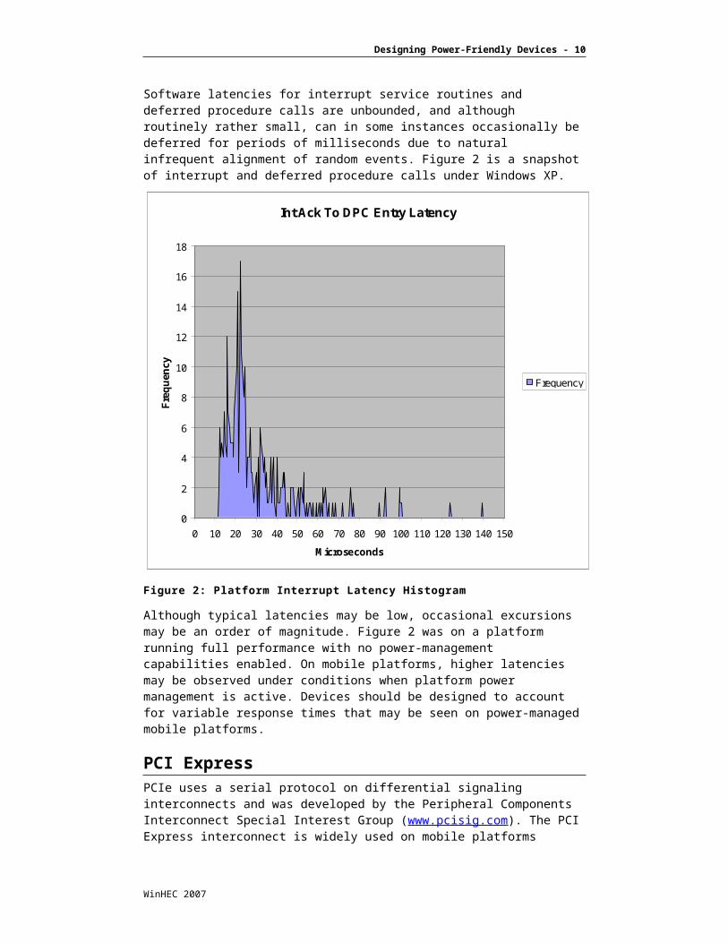
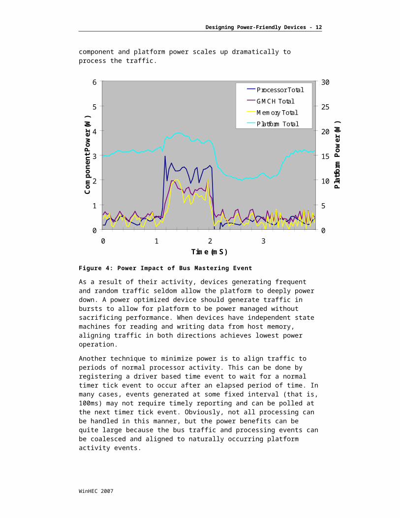
Bus Traffic AlignmentPCIe devices typically use bus-mastering to move data to or from the host. When bus master traffic is generated by a device, the platform immediately begins transitioning out of a low-power state to process the traffic. Figure 3 represents this flow and loosely depicts an Intel Core2 Duo mobile platform.
Figure 3: Platform Impact of Bus Mastering Event
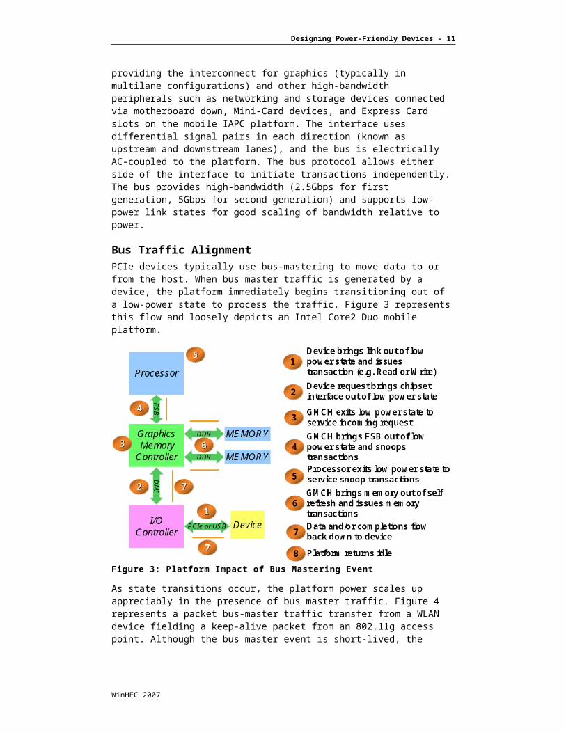
As state transitions occur, the platform power scales up appreciably in the presence of bus master traffic. Figure 4 represents a packet bus-master traffic transfer from a WLAN device fielding a keep-alive packet from an 802.11g access point. Although the bus master event is short-lived, the component and platform power scales up dramatically to process the traffic.
WinHEC 2007

Designing Power-Friendly Devices - 8
0
1
2
3
4
5
6
0 1 2 3
Time (mS)
Co
mp
on
ent
Po
wer
(W
)
0
5
10
15
20
25
30
Pla
tfo
rm P
ow
er (
W)
Processor Total
GMCH Total
Memory Total
Platform Total
Figure 4: Power Impact of Bus Mastering Event
As a result of their activity, devices generating frequent and random traffic seldom allow the platform to deeply power down. A power optimized device should generate traffic in bursts to allow for platform to be power managed without sacrificing performance. When devices have independent state machines for reading and writing data from host memory, aligning traffic in both directions achieves lowest power operation.
Another technique to minimize power is to align traffic to periods of normal processor activity. This can be done by registering a driver based time event to wait for a normal timer tick event to occur after an elapsed period of time. In many cases, events generated at some fixed interval (that is, 100ms) may not require timely reporting and can be polled at the next timer tick event. Obviously, not all processing can be handled in this manner, but the power benefits can be quite large because the bus traffic and processing events can be coalesced and aligned to naturally occurring platform activity events.
Coalescing InterruptsAn interrupt to the platform brings the host processor from Cx state to C0 state. This causes a significant spike in platform power consumption. Devices interrupt the platform for critical events, but generating frequent and random interrupts has a big impact on platform power. To minimize power consumption, devices should (to the extent possible) coalesce interrupts and should be designed not to generate frequent interrupts, especially when idle or under light load.
WinHEC 2007
Designing Power-Friendly Devices - 9
PCI Express Link Power ManagementThe PCI Express 1.0 and subsequent 2.0 Base Specification define the concept of several link states for a device in an active (D0) state. L0 is the active link state wherein transactions may be in flight; L0s is the first stage of idleness and is known as the standby state, which must be entered by a device supporting L0s in under 7s. In this state, some amount of power is saved by quiescing the link, but still maintaining all relevant circuitry to reactivate the link within typically less than 100 symbol times. ASPM L1 is the next level of power savings known as lower power standby, where the link enters a deeper level of power savings and the device can optionally power off its PLL. The PCIe specification also specifies a model for software to programmatically discover the link latency structures from the top of the system hierarchy to the endpoint and then evaluate whether the path for these latencies exceed what a device can tolerate, thereby setting the link active state power management policy accordingly on a link-by-link basis.
Unfortunately, the current specified methodology is insufficient and leads to several key problems for devices to make use of lower power link states. Specifically, it is observed that:
Devices mainly use a timeout-based policy for progression from L0L0sL1.
In Intel mobile platforms with key power management features such as Deeper Sleep (C4), the latency for issuance of a transaction on a given endpoint link, until the transaction completes in memory and potentially also snooped on the FSB, can be much larger than the maximum tolerable exit latency as computed through walking the link structure (this is presently ~55s in Intel Core2 Duo Mobile Platforms).
PCIe standards were enhanced in an ECN to the PCIe base specification 1.0a dated 12 January 2004, and also included in the 1.1 and 2.0 PCIe Base Specification releases, to include the concept of turning REFCLK off (and device PLL power down) via CLKREQ# protocol coupled with L1. In mobile platforms with this capability, devices that have long exit latencies using L1 with no REFCLK (device PLL power down) may result in host processor stalls resulting in I/O starvation or host processor performance issues.
The following sections provide recommendations to deal with the aforementioned problems.
WinHEC 2007
Designing Power-Friendly Devices - 10
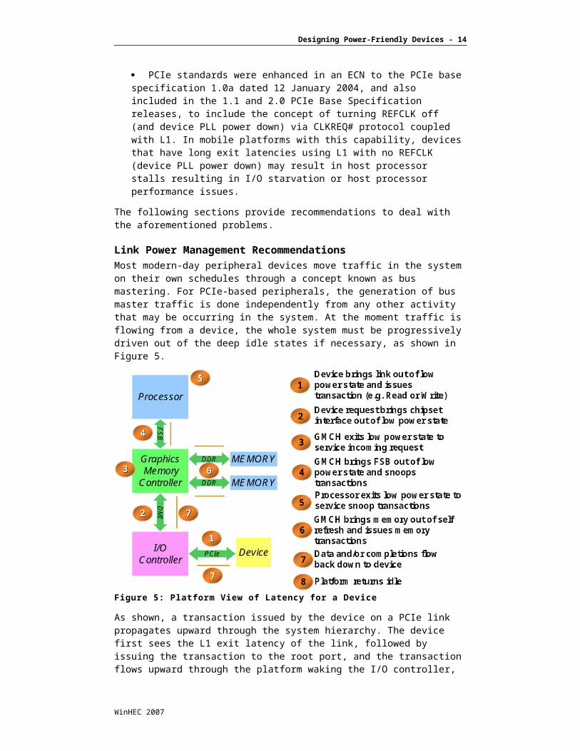
Link Power Management RecommendationsMost modern-day peripheral devices move traffic in the system on their own schedules through a concept known as bus mastering. For PCIe-based peripherals, the generation of bus master traffic is done independently from any other activity that may be occurring in the system. At the moment traffic is flowing from a device, the whole system must be progressively driven out of the deep idle states if necessary, as shown in Figure 5.
Figure 5: Platform View of Latency for a Device
As shown, a transaction issued by the device on a PCIe link propagates upward through the system hierarchy. The device first sees the L1 exit latency of the link, followed by issuing the transaction to the root port, and the transaction flows upward through the platform waking the I/O controller, the DMI link between the two components, followed by the graphics memory controller, DDR memory interfaces, and finally waking the processor to snoop the transaction.
This cascade of latencies may be much larger than the PCIe link exit latency it reports as being tolerable. The tolerable exit latency specified by the device in its configuration registers is only taken into account for the link exit latency, not for the transaction to memory completion. The PCIe specification handles only the link resume latency.
WinHEC 2007
Designing Power-Friendly Devices - 11
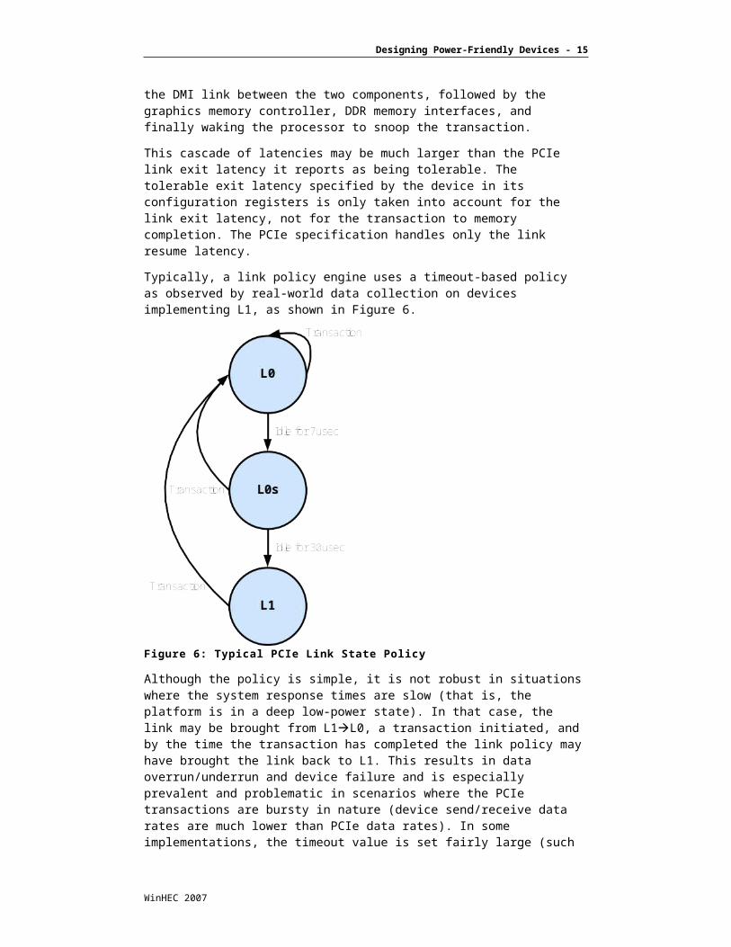
Typically, a link policy engine uses a timeout-based policy as observed by real-world data collection on devices implementing L1, as shown in Figure 6.
Figure 6: Typical PCIe Link State Policy
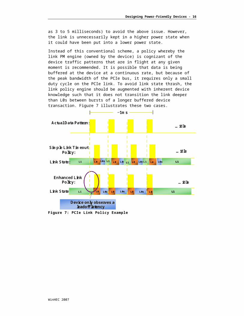
Although the policy is simple, it is not robust in situations where the system response times are slow (that is, the platform is in a deep low-power state). In that case, the link may be brought from L1L0, a transaction initiated, and by the time the transaction has completed the link policy may have brought the link back to L1. This results in data overrun/underrun and device failure and is especially prevalent and problematic in scenarios where the PCIe transactions are bursty in nature (device send/receive data rates are much lower than PCIe data rates). In some implementations, the timeout value is set fairly large (such as 3 to 5 milliseconds) to avoid the above issue. However, the link is unnecessarily kept in a higher power state when it could have been put into a lower power state.
WinHEC 2007
Designing Power-Friendly Devices - 12
Instead of this conventional scheme, a policy whereby the link PM engine (owned by the device) is cognizant of the device traffic patterns that are in flight at any given moment is recommended. It is possible that data is being buffered at the device at a continuous rate, but because of the peak bandwidth of the PCIe bus, it requires only a small duty cycle on the PCIe link. To avoid link state thrash, the link policy engine should be augmented with inherent device knowledge such that it does not transition the link deeper than L0s between bursts of a longer buffered device transaction. Figure 7 illustrates these two cases.
Figure 7: PCIe Link Policy Example
WinHEC 2007
Designing Power-Friendly Devices - 13
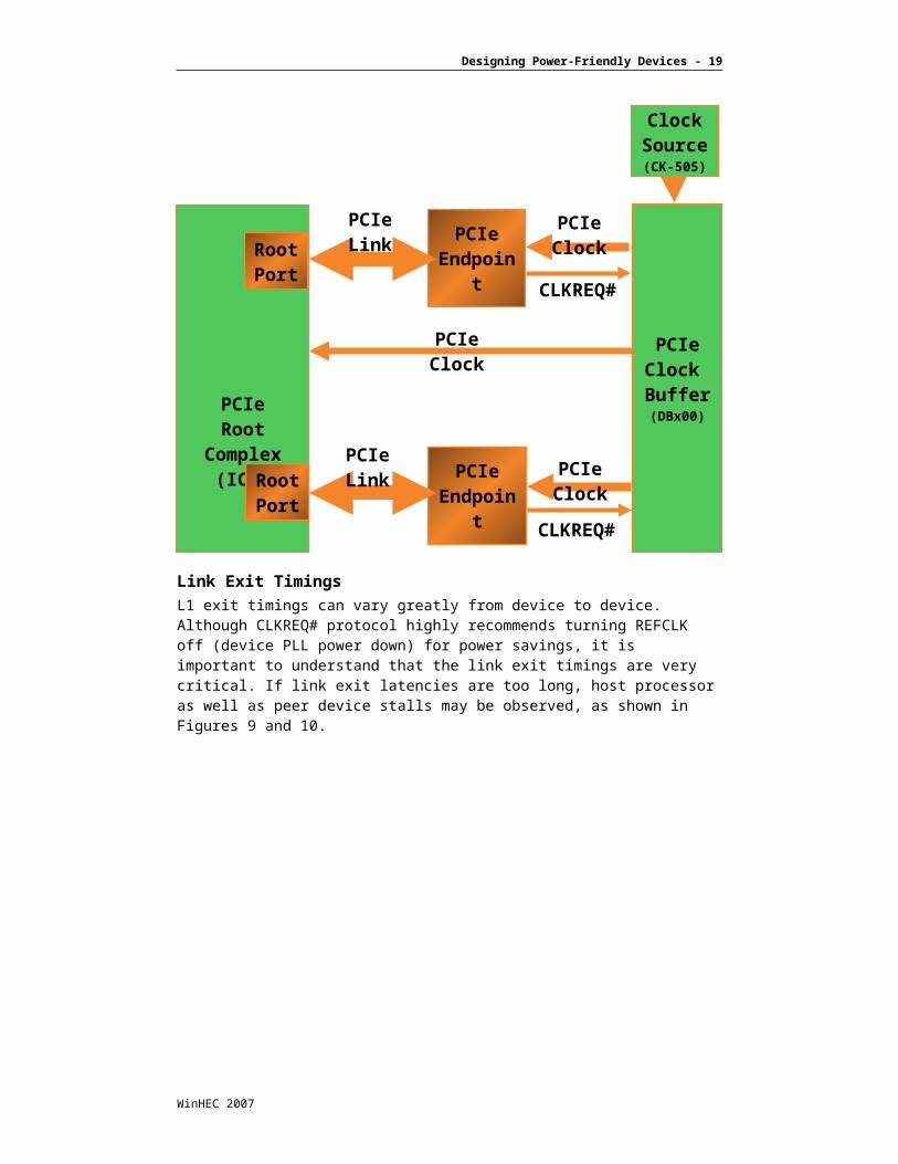
Another consideration is the use of the CLKREQ# protocol for turning REFCLK off (device PLL power down). The CLKREQ# signal is a signal that is routed to each PCI Express clock pair that indicates whether a device must reference the clock source at the present time. The protocol is designed such that the CLKREQ# signal may be shared across more than one device; however, this is typically not the case in IAPC platforms, as represented by Figure 8.
WinHEC 2007
Designing Power-Friendly Devices - 14
Figure 8: CLKREQ# Topology
WinHEC 2007
PCIeClock Buffer(DBx00)
PCIeRoot
Complex(ICH)
PCIeEndpoint
PCIeEndpoint
RootPort
RootPort
ClockSource(CK-505)
CLKREQ#
CLKREQ#
PCIe Clock
PCIe Clock
PCIe Clock
PCIe Link
PCIe Link
Designing Power-Friendly Devices - 15
Link Exit TimingsL1 exit timings can vary greatly from device to device. Although CLKREQ# protocol highly recommends turning REFCLK off (device PLL power down) for power savings, it is important to understand that the link exit timings are very critical. If link exit latencies are too long, host processor as well as peer device stalls may be observed, as shown in Figures 9 and 10.
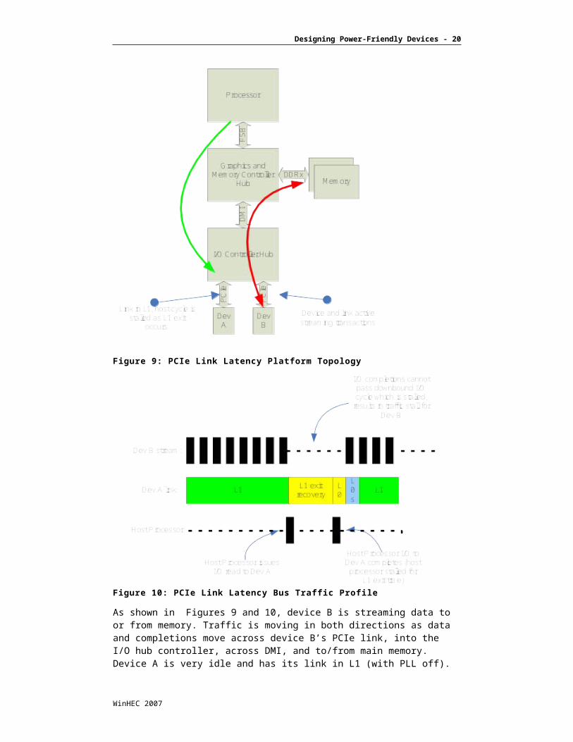
Figure 9: PCIe Link Latency Platform Topology
Figure 10: PCIe Link Latency Bus Traffic Profile
WinHEC 2007
Designing Power-Friendly Devices - 16
As shown in Figures 9 and 10, device B is streaming data to or from memory. Traffic is moving in both directions as data and completions move across device B’s PCIe link, into the I/O hub controller, across DMI, and to/from main memory. Device A is very idle and has its link in L1 (with PLL off). The processor issues an I/O read to device A. The I/O cycle is presented on the FSB and is issued downstream by the Graphics and Memory Controller Hub. Because the I/O operation is a serializing instruction, the host processor and chipsets cannot complete any other transactions until the I/O to device A is completed. As the I/O instruction flows downward, it becomes a serializing event across DMI, and the chipset in an attempt to retire transactions is forced to stall the I/O stream to device B until the I/O read to device A has completed. In this case, both the processor and peer I/O streams are stalled for the duration of the L0 recovery time (L1 exit times) for device A. As such, minimizing L1 exit timings is a critical design parameter for power-friendly PCIe devices. It is recommended that the L1 exit latency (even with device PLL shutdown) not exceed ~30sec.
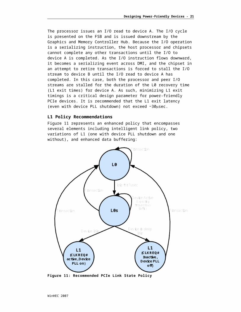
L1 Policy RecommendationsFigure 11 represents an enhanced policy that encompasses several elements including intelligent link policy, two variations of L1 (one with device PLL shutdown and one without), and enhanced data buffering:
Figure 11: Recommended PCIe Link State Policy
Using this methodology, a device can better manage link policies based on traffic. By providing multiple variations of L1 (both with device PLL power down and without), the link latencies can be more progressively managed to achieve both deep power savings when deeply idle, and good power savings when operating between meaningful periods of activity.
WinHEC 2007

Designing Power-Friendly Devices - 17
Universal Serial Bus 2.0 (USB 2.0)The Universal Serial Bus 2.0 specification is defined by the Universal Serial Bus Implementer’s Forum (www.usb.org) and supersedes and is backwards-compatible with the USB 1.1 specification. The USB 2.0 specification encompasses three distinct data rates: low speed at 1.5 Mbps, full speed at 12 Mbps, and high speed at 480 Mbps. USB 2.0 uses a 4-pin bus with two differential signaling lines (D+/D-). Fundamentally, the USB 2.0 bus is a polled bus in that data and control transactions are initiated by the host, not the device. Because polling in this case translates to power consumption, device design techniques are especially important. The USB 2.0 bus standard has a low-power state known as suspend, but today the latencies associated with entry and exit make it problematic to use as a dynamic flow control and link power management mechanism.
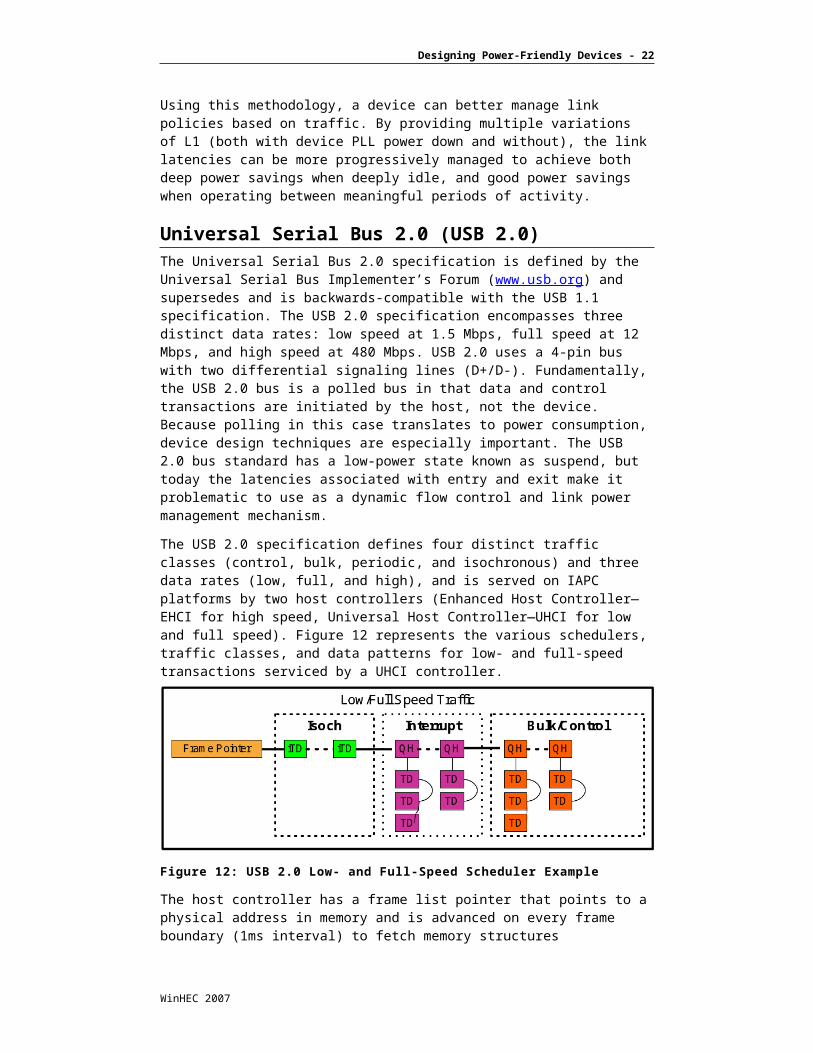
The USB 2.0 specification defines four distinct traffic classes (control, bulk, periodic, and isochronous) and three data rates (low, full, and high), and is served on IAPC platforms by two host controllers (Enhanced Host Controller—EHCI for high speed, Universal Host Controller—UHCI for low and full speed). Figure 12 represents the various schedulers, traffic classes, and data patterns for low- and full-speed transactions serviced by a UHCI controller.
Figure 12: USB 2.0 Low- and Full-Speed Scheduler Example
The host controller has a frame list pointer that points to a physical address in memory and is advanced on every frame boundary (1ms interval) to fetch memory structures (descriptors) that tell the host controller how to poll the device. Operating system software is responsible for laying out descriptors in memory that define for a given 1-ms interval the transactions that should be initiated. In Windows operating systems, periodic transfers are layered first starting with isochronous transfers, which are allocated fixed bandwidth and are thus placed first in the list. After the isochronous transactions are scheduled, the operating system typically places periodic interrupt transactions that represent data polls from devices with some amount of periodicity (typically in binary tree fashion generating polls at 1ms, 2ms, 4ms, 8ms, 16ms, 32ms, and so on). Finally, control and bulk transfers are appended to the end and typically linked end to end. The host controller DMA engine consumes all remaining bandwidth left after periodic transfers for asynchronous transfers until the start of the next frame boundary approaches.
WinHEC 2007

Designing Power-Friendly Devices - 18
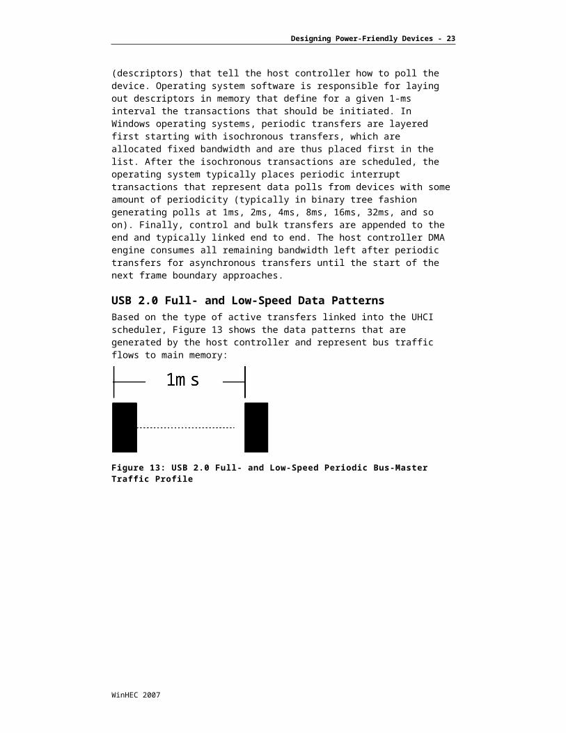
USB 2.0 Full- and Low-Speed Data PatternsBased on the type of active transfers linked into the UHCI scheduler, Figure 13 shows the data patterns that are generated by the host controller and represent bus traffic flows to main memory:
Figure 13: USB 2.0 Full- and Low-Speed Periodic Bus-Master Traffic Profile
In this case, the scheduler is performing only periodic transfers and generates bus traffic every 1ms. The width of the bus-master transfers depends on the amount of data returned by the devices as well as whether the devices ACK the transactions and return data (versus NAK the transactions and return no data).
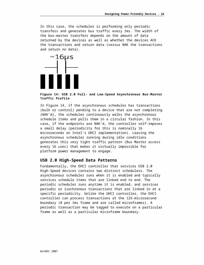
Figure 14: USB 2.0 Full- and Low-Speed Asynchronous Bus-Master Traffic Profile
In Figure 14, if the asynchronous scheduler has transactions (bulk or control) pending to a device that are not completing (NAK’d), the scheduler continuously walks the asynchronous schedule items and polls them in a circular fashion. In this case, if the endpoints are NAK’d, the controller self-imposes a small delay (periodicity for this is nominally 16 microseconds on Intel’s UHCI implementation). Leaving the asynchronous scheduler running during idle conditions generates this very tight traffic pattern (Bus Master access every 16 sec) that makes it virtually impossible for platform power management to engage.
USB 2.0 High-Speed Data PatternsFundamentally, the EHCI controller that services USB 2.0 High-Speed devices contains two distinct schedulers. The asynchronous scheduler runs when it is enabled and typically services schedule items that are linked end to end. The periodic scheduler runs anytime it is enabled, and services periodic or isochronous transactions that are linked in at a specific periodicity. Unlike the UHCI controller, the EHCI controller can process transactions at the 125-microsecond boundary (8 per 1ms frame and are called microframes). A periodic transaction may be tagged to execute on a particular frame as well as a particular microframe boundary.
WinHEC 2007
Designing Power-Friendly Devices - 19
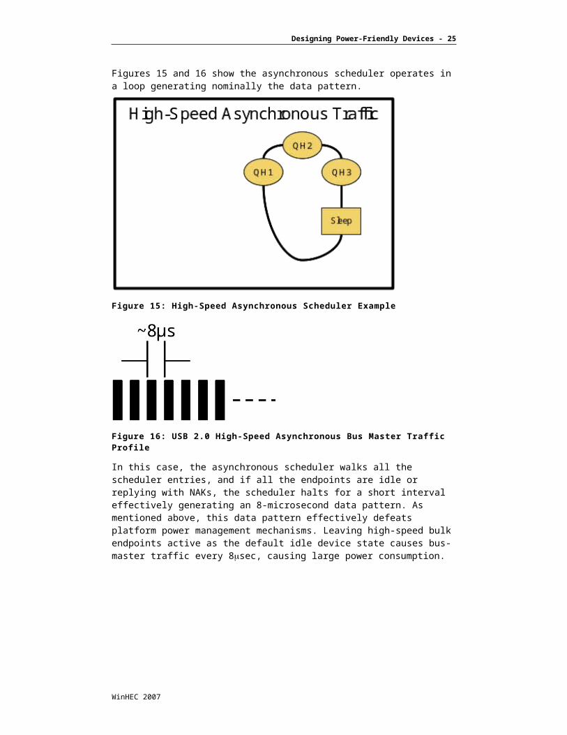
Figures 15 and 16 show the asynchronous scheduler operates in a loop generating nominally the data pattern.
Figure 15: High-Speed Asynchronous Scheduler Example
Figure 16: USB 2.0 High-Speed Asynchronous Bus Master Traffic Profile
In this case, the asynchronous scheduler walks all the scheduler entries, and if all the endpoints are idle or replying with NAKs, the scheduler halts for a short interval effectively generating an 8-microsecond data pattern. As mentioned above, this data pattern effectively defeats platform power management mechanisms. Leaving high-speed bulk endpoints active as the default idle device state causes bus-master traffic every 8sec, causing large power consumption.
WinHEC 2007
Designing Power-Friendly Devices - 20
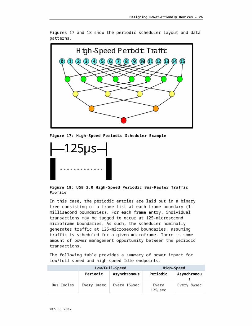
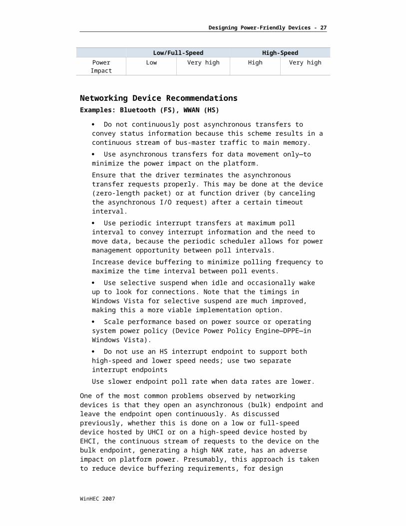
Figures 17 and 18 show the periodic scheduler layout and data patterns.
Figure 17: High-Speed Periodic Scheduler Example
Figure 18: USB 2.0 High-Speed Periodic Bus-Master Traffic Profile
In this case, the periodic entries are laid out in a binary tree consisting of a frame list at each frame boundary (1-millisecond boundaries). For each frame entry, individual transactions may be tagged to occur at 125-microsecond microframe boundaries. As such, the scheduler nominally generates traffic at 125-microsecond boundaries, assuming traffic is scheduled for a given microframe. There is some amount of power management opportunity between the periodic transactions.
The following table provides a summary of power impact for low/full-speed and high-speed Idle endpoints:
Low/Full-Speed High-Speed
Periodic Asynchronous Periodic Asynchronous
Bus Cycles Every 1msec Every 16sec Every 125sec Every 8sec
Power Impact Low Very high High Very high
WinHEC 2007
Designing Power-Friendly Devices - 21
Networking Device RecommendationsExamples: Bluetooth (FS), WWAN (HS)
Do not continuously post asynchronous transfers to convey status information because this scheme results in a continuous stream of bus-master traffic to main memory.
Use asynchronous transfers for data movement only—to minimize the power impact on the platform.
Ensure that the driver terminates the asynchronous transfer requests properly. This may be done at the device (zero-length packet) or at function driver (by canceling the asynchronous I/O request) after a certain timeout interval.
Use periodic interrupt transfers at maximum poll interval to convey interrupt information and the need to move data, because the periodic scheduler allows for power management opportunity between poll intervals.
Increase device buffering to minimize polling frequency to maximize the time interval between poll events.
Use selective suspend when idle and occasionally wake up to look for connections. Note that the timings in Windows Vista for selective suspend are much improved, making this a more viable implementation option.
Scale performance based on power source or operating system power policy (Device Power Policy Engine—DPPE—in Windows Vista).
Do not use an HS interrupt endpoint to support both high-speed and lower speed needs; use two separate interrupt endpoints
Use slower endpoint poll rate when data rates are lower.
One of the most common problems observed by networking devices is that they open an asynchronous (bulk) endpoint and leave the endpoint open continuously. As discussed previously, whether this is done on a low or full-speed device hosted by UHCI or on a high-speed device hosted by EHCI, the continuous stream of requests to the device on the bulk endpoint, generating a high NAK rate, has an adverse impact on platform power. Presumably, this approach is taken to reduce device buffering requirements, for design simplicity, and for low latency. Unfortunately, this approach is a disaster from a power perspective. Test results have shown that in a system whose idle power is measured to be 10W, the power consumption is doubled to 20W when a USB networking device is plugged in, even when there is no network traffic.
WinHEC 2007
Designing Power-Friendly Devices - 22
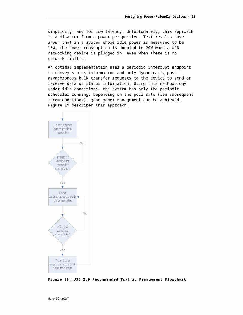
An optimal implementation uses a periodic interrupt endpoint to convey status information and only dynamically post asynchronous bulk transfer requests to the device to send or receive data or status information. Using this methodology under idle conditions, the system has only the periodic scheduler running. Depending on the poll rate (see subsequent recommendations), good power management can be achieved. Figure 19 describes this approach.
Figure 19: USB 2.0 Recommended Traffic Management Flowchart
When this model is employed, asynchronous transfers are used only for data movement. After the periodic endpoint is opened, the driver waits for the periodic endpoint to complete a transaction. After the periodic endpoint transaction completes, the function driver posts an asynchronous transfer to move the data to or from the device depending on what type of indication was provided by the interrupt endpoint. After the data transfers have been completed, it is important that the function driver terminate transfer requests at the device (by having the device ACK the transfer and return a zero-length packet) or at function driver (by canceling the asynchronous transfer request) after a certain timeout interval to ensure that the asynchronous endpoints are removed from the scheduler. This ensures that the
WinHEC 2007
Designing Power-Friendly Devices - 23
scheduler is halted properly, allowing the platform to enter a low-power state and thus reducing the power impact of the device.
Additionally, it is important to maximize device buffering such that the poll rate of the device may be as slow as possible. A power-friendly device should employ poll rates of at least 1ms, and preferably 2-4ms or higher. It may also be possible to support various periodic endpoints at different rates that are used selectively based on the bandwidth needs of the device. In such a case, if the device has a high-speed connection, device buffering may mandate a 1-ms poll rate interval, whereas when the device has a slower connection, the device has sufficient buffering to tolerate a 4-ms poll rate.
Devices should support and use selective suspend whenever the device is idle and only occasionally wake up to look for activity, incoming connections, or device state changes. This is important because a device should not continuously post periodic (and certainly not asynchronous) transfers if it is not actively connected. As in the case where the device is in a mode that it is scanning or looking for network connection, it should take care to do this very infrequently or provide hardware capabilities in the device to do this without requiring continuous USB 2.0 transfer support from the USB 2.0 function driver.
Device vendors should also take advantage of key Windows Vista enhancements. Use of selective suspend on Windows Vista is much improved (shorter latencies) versus older versions of Windows operating systems, and its use should be reevaluated for use on devices where it may not have been usable on previous versions. The other opportunity for Windows Vista is to expose the ability to scale performance based on power source or operating system power policy (DPPE in Windows Vista). For proper implementation of DPPE, refer to documentation on the Microsoft Web site.
Streaming Device RecommendationsExamples: DVB TV (HS), Audio (FS/HS), Cameras (HS)
Use isochronous endpoints to move streaming data. Isochronous data transfers are allocated a fixed amount of bandwidth and scheduled on the periodic scheduler to ensure that they happen on time with highest priority.
Provide as much buffering as possible to maximize spacing between packet movements to maximize platform power management opportunity.
Schedule and maximize the time interval between isochronous packets based on device buffering capabilities and streaming device bandwidth requirements.
Streaming devices are associated with application-level software that sources or consumes data to/from the device. Ensure that the application properly cleans up driver requests on exit or inactivity (pause, mute, and so on) to ensure that schedule entries do not remain on the scheduler.
Support selective suspend and implement aggressively when the device is not in use to ensure that the device is properly powered down when idle.
Properly manage and carefully consider use of the feature that provides instant-on capabilities to continuously poll a device for user input when the device is not in use.
Consider not using this type of feature on battery-powered mobile platforms, or provide ability for the device to buffer the interactive events when not in use. Such an example of an instant on feature is a webcam snapshot button.
WinHEC 2007
Designing Power-Friendly Devices - 24
One common characteristic observed in streaming types of devices is common usage of asynchronous bulk endpoints for movement of streaming data. There are several problems with this approach. Firstly, asynchronous bandwidth supporting very high sustained data rates is shared across ports on a given controller, and thus, achievable bandwidth may vary dramatically as other devices on a given host controller generate transfers concurrently. This can be readily observed with two devices that use asynchronous transfers for streaming content. In many cases, the streams break up or become unstable while two devices are active on the same host controller at the same time. Bandwidth is shared across host controllers, and because USB 2.0 is a broadcast bus, multiple streams are time-sliced versus served concurrently.
On the contrary, the isochronous traffic class is time scheduled and properly allocated by host software. As such, a device can receive a dedicated amount of bandwidth to service its endpoint, and this traffic runs at effectively a higher priority level than asynchronous transactions. Because isochronous transfers are scheduled on the periodic schedule, the power management effectiveness of using isochronous traffic class may also be enhanced over using asynchronous bulk transfers.
When the application stream is shut down, care must be taken in the device function driver to ensure that the application properly cleans up driver requests on exit or inactivity (pause, mute, and so on).To avoid dangling transactions pending on the device, which remain un-serviced or continually retried.
Because streaming devices are typically used on a demand basis (when requested by application software), they are prime candidates for use of selective suspend. Selective suspend should be used aggressively for these types of devices after ensuring that the device has been properly stopped.
Many devices of this category support a so-called "Instant-On" feature, whereby the device has local buttons that are typically serviced by a periodic endpoint. On mobile platforms, the buttons require a continuously running periodic interrupt endpoint to poll the button, and this wastes power. It is recommended that devices purposefully designed for mobile platforms do not support buttons, or if they do support buttons that must be functional, work with the platform designer to provide platform-level notifications mechanisms through sideband signals and ACPI BIOS modifications. By using such a scheme, the notifications may be delivered on demand and the function driver can be the target of these notifications providing the same net effect for Instant-On features without having to continuously run the periodic scheduler.
WinHEC 2007
Designing Power-Friendly Devices - 25
Human Interface Device RecommendationsExamples: Keyboard (LS), Mouse (LS/FS)
Use periodic endpoints and maximize spacing between polls, because this maximizes platform power-management effectiveness.
Use selective suspend as much as possible to completely idle the scheduler; however, because of the human interactive nature of devices in this category, careful attention should be paid to the following points:
Ensure that the device supports full functionality while in selective suspend.
Ensure that the device does not drop user input or feel overly sluggish, where an end user could discern the difference of being active or idle.
Ensure that the device does not lose visible features while in Selective Suspend (such as LEDs) because this could result in end-user support questions.
Human interface devices (HIDs) use periodic endpoints typically at low speed although recently gaming mouse devices that use full-speed endpoints are available. Few optimizations are available for these devices as far as scheduler management other than maximizing the duration between polls on the periodic interrupt scheduler.
A key element to consider is use of Selective Suspend coupled to a robust idle detection policy. To avoid end-user artifacts, it’s important to detect idleness very cautiously, and to not lose functionality while in selective suspend (the device should not appear sluggish or drop keystrokes). It is also important to ensure that the device does not lose visible features while in selective suspend (such as LEDs).
Occasional Use Device RecommendationsExamples: Fingerprint Sensor (FS), GPS (FS)
Use asynchronous transfers when requested by application software to maximize idle opportunity when the device is not needed or in use.
Use asynchronous transfers for data movement only to minimize the power impact on the platform.
Do not continuously post asynchronous transfers to convey status information because doing so results in continuous bus-master traffic requests that defeat platform power management.
Ensure that the driver terminates the asynchronous transfer requests properly. This may be done at the device (zero-length packet) or at function driver (by canceling the asynchronous I/O request) after a certain timeout interval.
Use selective suspend aggressively when the device is not needed, which in this category can be easily determined by:
No app consumer loaded (GPS)
Authentication complete (fingerprint sensor)
Properly manage and carefully consider use of feature that provides instant-on capabilities that continuously poll a device for user input when the device is not in use.
Consider not using this type of feature on battery-powered mobile platforms, or provide ability for the device to buffer the interactive events when not in use.
WinHEC 2007
Designing Power-Friendly Devices - 26
Flash drives with embedded hub, typically used for proprietary security support, should implement security features without the need of an embedded hub, because the presence of a device behind a hub results in continuous periodic polling by the operating system.
This class of devices falls into the category of being occasionally used in the system To provide location information when asked from applications or to export a security interface that is used at times for end-user authentication (boot, wake, and so on). As such, these devices should use a combination of the techniques described in the previous section.
Devices of this category should use asynchronous bulk transfers when requested by the application and should properly terminate (via zero-length packet or canceling the transaction through the device stack) the asynchronous transfers when idle or when the device requests have ended or have been terminated. Devices should not continuously post asynchronous transfers to convey status information, and if a continuous stream of data is needed, it should be done through periodic interrupt endpoints.
Use selective suspend aggressively when device not needed. This is especially important in this case because devices that expose a periodic endpoint and do not have a driver loaded trigger Windows to continuously poll the device. After the function driver is loaded against the device, it should place the device promptly into selective suspend if there are no outstanding I/O requests to the device.
Devices of this category also sometimes support an instant on feature, and the recommendations from the previous section should apply here as well.
As a special case note, flash drives with an embedded hub, typically used for proprietary security support, should implement security features without the need of an embedded hub. Embedded hubs are continuously polled by the operating system unless all devices downstream of the hub are placed into selective suspend.
Implementation DetailsThe following section shows the flow for using an interrupt endpoint for bulk transfers under Windows including code snippets.
Function Driver Interrupt Poll Bulk Read Method1. Create IRP to be used to poll interrupt endpoint.
2. Build URB Interrupt.
3. Submit IRP Interrupt In.
4. Upon IRP Interrupt In Completion.
5. Build URB to read bulk endpoint.
6. Submit IRP Bulk In.
WinHEC 2007
Designing Power-Friendly Devices - 27
Submitting Bulk/Interrupt INThe following code sequence is used to submit either an asynchronous bulk or periodic interrupt transfer (note bold-italics where the transfer type is selected):
UsbBuildInterruptOrBulkTransferRequest(Urb,sizeof(struct _URB_BULK_OR_INTERRUPT_TRANSFER),DevExt->Pipe->PipeInformation.PipeHandle,Data,NULL,sizeof(UCHAR),(USBD_SHORT_TRANSFER_OK | USBD_TRANSFER_DIRECTION_IN),NULL);nextStack = IoGetNextIrpStackLocation(Irp);nextStack->MajorFunction = IRP_MJ_INTERNAL_DEVICE_CONTROL;nextStack->Parameters.Others.Argument1 = (PVOID) urb;nextStack->Parameters.DeviceIoControl.IoControlCode = IOCTL_INTERNAL_USB_SUBMIT_URB;IoSetCompletionRoutine(Irp,CompletionRoutine,Context,TRUE,TRUE,TRUE);IoMarkIrpPending(Irp);ntStatus = IoCallDriver(deviceExtension->TopOfStackDeviceObject, Irp);
Note: The above example is from Usbdlib.h in the Windows Driver Kit, and is copyrighted by Microsoft Corporation. The use of this code is governed by the terms of the Windows Driver Kit license agreement.
ConclusionEnergy efficiency is important for all computing platforms – battery life for mobile platforms and ENERGY STAR compliance for desktops and servers. Much has been done on the platforms to reduce power consumption, but they are not optimized for power in cases when data is moving in the platform. The impact of devices (even low-power ones) on platform power can be appreciable. New bus standards such as PCI Express and USB 2.0 are the Interconnects of choice for everything from walk-up ports, flexible build to order (BTO), and configure to order (CTO) at original equipment manufacturers, through standards such as Express Card and Mini-Card form factors.
Straightforward design techniques such as link state management and latency reduction, and recommendations for design principles such as aligning bus traffic and coalescing interrupts offer significant power reductions at the platform level. For USB 2.0, proper use of traffic classes, improved use of selective suspend, and proper idle detection through applications and end-user visible buttons can reduce power significantly without affecting performance.
WinHEC 2007
Designing Power-Friendly Devices - 28
Call to Action When designing devices, understand the platform power impact of design choices being made.
Ensure that devices have sufficient buffering to accommodate higher platform response time seen due to platform power management during idle and semi-active traffic scenarios.
Align bus traffic and coalesce interrupts to allow platform to have higher low-power state residency.
Implement intelligent link state management based on traffic patterns,
For USB 2.0 devices, follow design guidelines to improve platform energy efficiency.
WinHEC 2007


