Embed Size (px)
Citation preview

A smarter perspective
© CIMAC 2019
WinGD 12X92DF, the Development of the Most Powerful Otto Engine Ever9 - New Engine Developments - Gas & Dual Fuel
Paper 425
Dominik Schneiter, WinGDVice President R&D
Stefan Goranov, WinGDProgram Manager Hybridisation
Marcel Ott, WinGDGeneral Manager Operations
Patrik Printz, WinGDProject Manager DF
ABSTRACT
For years, the public and regulatory pressure continuously forces shipping to adapt new enginetechnologies to ensure a cleaner environmental footprint. Additionally, to guarantee greentransportation to their customers, shippers are challenged by major cargo owners and logisticcompanies to go even further beyond the thresholds set by regulators .
In such business environment, the pressure on WinGD increased to make the most powerful enginesapplied in very large container vessels available also with X-DF technology. The X-DF burns LNG ina lean cycle, which practically omits particulate matter (PM), sulphur oxide (SOx) emissions anddrastically reduces Nitrogen Oxides (NOx) to below IMO Tier III level. Additionally, the carbon oxide(CO2) and CO2 equivalent are also reduced to below diesel combustion levels. Those were strongarguments for the 1st customer to commit into a project with the new engine and propulsiontechnology for container vessel designs with the size of 22’000TEU.
In this paper, WinGD experts will elaborate how the experience and knowledge gained with X-DFengines in the mid bore range (i.e.: X62-DF/ X-72DF) were up-scaled and adapted to the currentbiggest bore size of the X-92DF. In particular, it will address the challenges with achieving ahomogenous gas air mixture, igniting the combustion and the thermal loading of the components. Itwill also address the particulars of the lean burning cycle and the effect it has on the engine structurewith related design upgrades. Additionally, the paper will show the complexity associated withcontrolling such an engine. It also gives some insights on the development of the next generationWinGD control system, which took place in parallel with the base engine development.
Among the different development tasks, the unique X-DF technology and its potential for the shippingindustry will be discussed. The technology is still at the beginning of it’s lifecycle, and majordevelopment steps are still expected. The paper will highlight some of them. Upon the Vancouvercongress, test results from the very 1st 12X92DF will likely be available and can briefly be summarizedin the presentation.
With the 12X92DF, WinGD has now undertaken the task to proof that also largest engines canoperate in a lean burning cycle, and is therefore offering completely new propulsion options to theindustry, which can be adapted and optimized according requirements of cargo owners, shippers andpublic views.
Powered by TCPDF (www.tcpdf.org)

CIMAC Congress 2019, Vancouver Paper No. 425 Page 3
1 INTRODUCTIONWith the 12X92DF, Winterthur Gas & Diesel(WinGD) undertook to develop the most powerfullean burning, pre-mixed Otto cycle reciprocatingcombustion engine ever.
The key technology driver for development of alean burning engine running on liquified naturalgas (LNG) as fuel, were the unprecedentedenvironmental benefit with the clean fuel,combined with a combustion cycle that allows tocontrol the Nitrogen Dioxides (NOx) well belowcurrent emission limit levels.
Key gaseous local pollutions normally present withthe standard diesel cycle engines running onresidual fuels, like Sulphur Dioxides (SOx), NOxand particulate matters (PM) are mostlyeliminated. In addition, and considering allcurrently known and IPCC (IntergovernmentalPanel on Climate Change) declared green housegases, the green house gas emission footprint ofa LNG burning ship with a lean burning cycle mainengine has been reduced up to 20% comparedwith a standard diesel or heavy fuel oil (HFO)application.
Making available a considerable cleaner solutioncompared to todays gaseous emission referencesin merchant shipping has been recognized andawarded by well-known shipping industryorganizations. The WinGD X-DF concept earnedamongst other below recognitions:
· The 2018 Marine Propulsion EmissionReduction Award
· The 2017 Marine engineering of the Yearaward issued by the Japan Institute of Marineengineering
· Shortlisted 2018 Safety4 Sea SustainabilityAward
· Shortlisted 2018 The Motorship emissionreduction Award.
However, it is obvious that an engine powered byfossil fuel like the X-DF with liquified natural gas(LNG) in gas mode will by itself not be enough tomeet the ambitious International MaritimeOrganization (IMO) declared green house gas(GHG) reduction targets of the shipping industry.We at WinGD see the lean burning cycle appliedon a slow speed 2-stroke as one feasible way toaccommodate a higher variety of future CarbonDioxide (CO2) neutral fuel, hence enabling theIndustry to seek and develop indeed sustainablesolutions.
To make a platform available, eventually meetingcurrent and future emission targets, WinGD fromthe beginning was preparing to roll out the leanburning technology to the entire engine portfolio.
Initially, the lean burning 2-stroke slow speedtechnology was developed with inheritingknowledge from medium speed applications,particularly profiting from the experience andexpertise of Wärtsilä developed solutions [1].
In this paper the technical challenges of a bigbore, big volume combustion chamber incombination with a lean burning cycle areaddressed. The experience and observations ofsmaller sized engines are reflected. The papergives insights how WinGD further developed thetechnology with the lessons learned and how weensure a working system without having thepossibility of a prototype test.
Additionally, the specific demands to theadvanced control system, which is not onlycontrolling 2 complete different combustion cycles,but newly also provides for a high data throughputand effective data analysis in spite of“digitalization” and predicted maintenancecapabilities.
A short section in the paper will also address theapplication and fuel logistic challenges the 1st shipoperator had to address with the innovativeapproach.
Despite the technical challenges and theambitious schedule, the project has progressedwell. It is expected that the 1st engine will start inQ1-2019, and some 1st operational results can beshared during the CIMAC 2019 Vancouvercongress.
2 ENGINE DESIGN DETAILS2.1 GeneralThe herein discussed 12X92DF engine will beinstalled on a series of 9 x 22’000TEU containervessel trading between Asia and Europe. Theships and the engines are being produced byWinGD’s partner companies within the ChinaState Shipbuilding Cooperation CSSC.
The FAT of the first engine is planed in early June2019, just at the time of the Vancouver congress.The 1st vessel delivery to the customer will be mid2020.

CIMAC Congress 2019, Vancouver Paper No. 425 Page 4
The engine selected is rated at its maximumpower output and develops 63’840kW at 80 rpmsin both, diesel and gas mode operations.
Table 1: Engine particulars
12X92DFBore 920 mmStroke 3468 mmSpeed 80 rpmPower 63840 kWMass 2140tLengthTotal Height
22.87m15.92m
2.2 Combustion System Development2.2.1 Emission footprintThe NOx emissions in diesel mode comply withIMO Marpol VI Tier ll NOx regulations. In gasmode, the NOx emissions are well below the IMOTier lll NOx limits without exhaust gas aftertreatment.
Fundamentally, based on the gas composition,LNG fueled engines reduce CO2 output byapprox. 20% caused by the reduced C content inthe fuel. For pre-mixed, lean burning engineshowever, a certain fuel slip is a reality and need tobe addressed. This fuel slip with LNG operatedcontains CH4 or methane, which is also a IPCCdefined green house gas. Consequently, themethane slip needs to be reviewed when defininga total emission footprint of this engine. Seefigure 2 showing the effective emissions of an X-DF engines compared to the Industry benchmark.
Figure 1: overview pollutants including CO2e
Due to the larger combustion space in comparisonto the former, smaller DF engines, andconsequent favorable combustion volume to wallsurface ratio, a further reduction of the specificTHC/methane emissions is expected. Please findan extended analysis of green house gas relevantemissions of X-DF engines in CIMAC paper 426/2019.
2.2.2 Gas admission and pilot injectionIn many aspects, the design of the X92DF is ascaled-up version of smaller DF engines [1].
Two gas admission valves (GAVs) are mountedon each cylinder liner. The GAVs are connected totwo gas manifolds that run along the engine onboth sides.
Pneumatic shut-off and vent valves are arrangedat both ends of the gas manifolds for a fastrelease of the gas pressure providing for therequired double block and bleed system.
Figure 2: Overview of gas admission
Two pilot injectors with their pre-chambers arearranged in each cylinder cover.
Additionally, the three main injectors for the dieseloperation are arranged in the same way as withthe standard X92 diesel application in eachcylinder cover.
The scaling-up approach not only reduces the riskof new initial design flaws, but also allows to keepthe effort for the initial manufacturing of the new,larger components lower. The X92DF is more atechnology evaluation, not a revolution.

CIMAC Congress 2019, Vancouver Paper No. 425 Page 5
2.2.3 Higher number of cylindersHowever, the higher number of cylinders requiredadaptations of the design and several designiterations during the development.
For instance, to avoid disturbing pressureoscillations in the long gas manifolds, the systemlayout was investigated and optimized bysimulating the fluid dynamics in detail.
Figure 3 simulation of pressure in gas manifold
Furthermore, and based on the mechanical FEManalysis of the gas pipes, additional elasticbellows are applied in the gas manifolds to reducethe stress triggered by thermal expansion.
The fast release and venting of the gas pressurefrom the manifolds is an important safety function,which could be realized with the same fast shut-offand vent valves as on smaller X-DF engines,despite the higher number of cylinders.
2.2.4 Integrated gas pressure regulationSo far, the DF engines were combined with anexternal gas pressure regulating unit called “gasvalve unit (GVU)”, a separate module that wasinstalled in the engine room. The GVU wasdesigned and delivered from a third-party supplier.
As a replacement for the GVU, WinGD developedan integrated gas pressure regulation (iGPR). Dueto its compact design, the iGPR can be arrangedon the platform of the engine. The function of theiGPR is controlled directly by the engine controlsystem.
The iGPR consists of several elements:
· Control valve for the accurate adjustmentof the gas pressure for the gas admission.
· Gas filter and gas flow meter.
· Automatic valves for the venting andinverting of the gas manifolds.
· Electric control unit with local panel.
All elements are of double wall design, like thegas manifolds and fulfil the requirements ofmarine classification societies and meet IMOSOLAS (International Convention for the Safety ofLife at Sea) standards.
Figure 4: integrated gas pressure regulation iGPR
2.2.5 Pre-chamber and pilot injectionFor ensuring a stable ignition at very low engineloads in gas mode also, the volume of the pre-chamber is scaled up. The nozzle geometry of thepilot injector and the related spray pattern isoptimized based on a CFD analysis. Thetemperature distribution of the pre-chamber and ofthe nozzle tip in particular, is optimised based ona thermal FEM analysis. For simplifying themaintenance, a sleeve between the pre-chamberand the cooling water is added to the design.
Figure 5: pre-chamber and pilot injector

CIMAC Congress 2019, Vancouver Paper No. 425 Page 6
2.2.6 Main injection system and nozzlesThe liquid fuel injection system from the dieselengine was taken over for the DF engine. Itconsists of three mechanical injectors per cylinderthat are controlled by a common injection controlunit ICU. One ICU per cylinder is located on thefuel rail.
So far, nozzles with a similar layout/geometrywere applied for diesel and DF engines. For theX92DF, atomizers with a more specific boregeometry were developed. The new nozzles aimto further improve the temperature distribution inthe combustion space, leading to lower thermalloads for the components and to lower NOxemissions. A new CFD based tool was used todevelop a model of the spray pattern, includingthe distribution of the jets, the evaporation of theliquid and the estimation of the combustionprocess and the related emissions.
Figure 3: ICU based main injection system
2.2.7 Turbo charger characteristics?Based on the experience with the smaller bore X-DF engines, a new turbocharger matchingstrategy for pre-mixed lean burning engines wasestablished together with the major turbochargermanufacturers.
The target is to reach the highest possibleturbocharger overall efficiency at high loads. Thisis considerably changing the characteristics ofturbochargers applied on 2-stroke slow speedengines (see figure 5).
Figure 4: X-DF TC matching strategy
For typical diesel engines, an accurate adjustmentof the scavenge pressure by an accurateturbocharger matching with an evaluated pressurecurve at part load is normal, while with X-DFengines, a larger variation of scavenge pressure istolerated but high efficiency at highest engineloads is desired.
The scavenge pressure on an X-DF engine is fine-tuned by an exhaust waste gate that by-passesexhaust gas around the turbine as part of theperformance control concept. With this system,lambda of the combustion can precisely beadjusted according current operation and ambientconditions.
2.2.8 Electric blowers with variable speedConventional auxiliary blowers on diesel 2-strokeengines are just switched on and off when thescavenge pressure is passing a pre-definedtrigger level. Such blower control is simple, buttowards very low engine loads in gas mode, thecombustion gets slow due to the lean and coolmixture. By reducing the air flow in a variable way,a smoother running of the engine can be achievedtowards very low loads. Consequently, frequencycontrolled auxiliary blowers are introduced asstandard for the X-DF engines.
2.2.9 Temperature dependent scavengepressure.
The speed of the pre-mixed combustion dependsnot only on the air to fuel ratio, but also on thetemperature of the scavenge air. It is possible,within reasonable limits, to compensate theaccelerating effect of a higher temperature withthe decelerating effect of a higher air to fuel ratioand vice versa. The engine control system adjuststhe scavenge pressure based on the measuredtemperature of the scavenge air and keeps the

CIMAC Congress 2019, Vancouver Paper No. 425 Page 7
combustion therefore more stable. The functionsimplifies the tuning of new engines by thelicensees, in particular for cold conditions.
2.2.10 Combustion processThe scaling-up of the gas combustion was carriedout by considering two main criteria:
Air/fuel ratio:
The turbo chargers were carefully selected forachieving a high total efficiency as well as a highair flow. In addition, slightly higher scavenge portswere applied for increasing the duration of thescavenging.
Gas mixing:
A primary mixing of the fuel gas into the air ismade by two gas jets. Despite that primary mixingtakes place in the relative low pressure of thescavenging (before start of compression), the jetsrequire a significant momentum to achieve theanticipated penetration lengths. The requiredmomentum is created by injecting the gas withapproximately sonic speed. The gas jets for theprimary mixing were scaled-up from the smallerreference X-DF engine by applying fluid dynamiccalculations for subsonic and supersonic flow.
Figure 5: gas air mixing in cylinder
A secondary gas mixing takes place during thecompression phase, driven by the air swirl in thecylinder. For a more efficient, but also accurateanalysis of the scavenging and the gas mixing, anew CFD tool was used. The new tool wasvalidated and models calibrated based on theresults from the smaller DF engines. The layout
for the secondary mixing of the X92DF is to alarge extent a scaled-up version of the X72DFengines.
The goal was to get a characteristic distribution ofthe gas. That distribution is not fully homogenous,but shows a certain stratification in the combustionvolume. For example, the zone below the exhaustvalve is only partially flushed with fresh air andcontains a significant amount of hot air from theformer cycle. Therefore, a mixing of gas into thatzone is not desired.
2.2.11 Fuel sharingThe fuel sharing mode allows to burn gas andliquid fuel simultaneously. The operator canchoose a share of up to 50% liquid fuel. So far,the additional flexibility is particularly applied forLNG carriers. It allows such LNG carriers toachieve the desired vessel speed even withlimited amount of natural boil-off gas, eliminatingthe need to apply a forced boil off.
But also for merchant vessel the fuel sharingmode can be utterly attractive. For instance,when experiencing gas aging or when the nextLNG bunker station is too far away to just run ongas. See chapter 3 “engine application” for moredetails.
Because a considerable part of the fuel is burnedin a diffusive regime, the fuel sharing mode istuned to be IMO Tier ll compliant [1].
2.2.12 Cylinder Oils for DF enginesBecause of the zero-sulphur content of LNG andonly low volume of pilot fuel, WinGD recommendsusing a cylinder oil in the range from BN 15 to 40to lubricate the X92DF engines.
The thermal stress of the piston runningcomponents including the cylinder oil on a DFengine can be higher than known from the dieselengine. The premixed flame leads to highertemperatures closer to the cylinder liner runningsurface compared to the diffusion flame knownfrom the Diesel engines. From experience it’sknown that this higher thermal stress on thecylinder oil can increase the risk of depositaccumulation on piston top land, piston ringgrooves and on the backside of the piston rings.These deposits can lead to reduced componentclearances and, engine operation modedependent, to piston running issues. Therefore,WinGD recommends using cylinder oils whichhave a high oxidation stability and a highdetergency level.
CIMAC Congress 2019, Vancouver Paper No. 425 Page 8
WinGD has a comprehensive oil validationprogram which includes an extensive laboratoryanalysis followed by an extended field test. Everyoil which is mentioned on the WinGD list ofvalidated oils has passed this validation program.The list consists of a wide range of cylinder oilsfrom BN 15 to BN 140 to cover LNG, distillatefuels and as well HFO up to 3.5 % sulphur. Theportfolio is ready for every fuel available which aWinGD DF engine can burn.
The DF engines are still new on the market and afurther optimization of the cylinder oil portfolio andthe oil formulations is required to enhance thepiston running performance. Upcoming engineswith further increased efficiency will be even moredemanding for the cylinder oils. WinGD is in closecontact with all relevant oil and additivecompanies to address the challenges and tosupport the development of new generationcylinder oils.
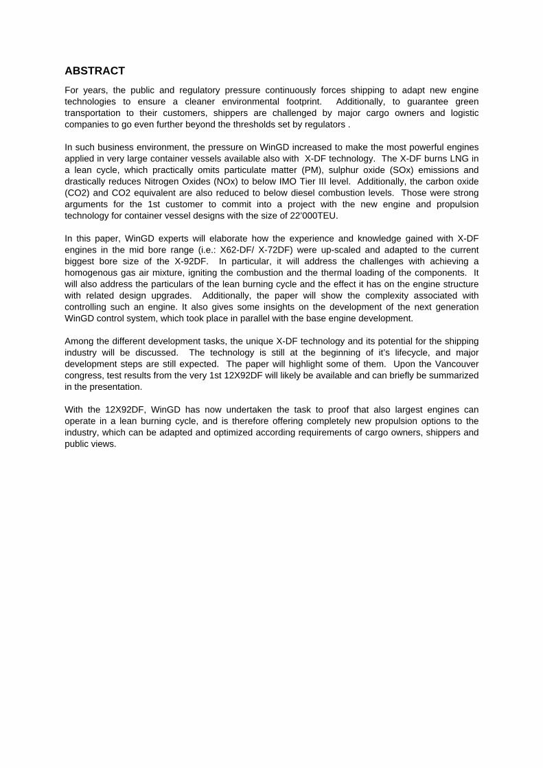
2.2.13 iCATWinGD introduced the iCAT (Integrated CylinderLubricant Auto Transfer system) to have thecorrect cylinder oil always and immediatelyavailable at the cylinder lubricating pump.Typically, a low and a high BN cylinder oil areselected to comply with LNG and a wide range ofliquid fuels.
iCAT eliminates the risk of feeding a wrongcylinder oil for hours into the cylinder, what couldlead to severe piston running issues. In the past,the entire oil amount in the piping system had tobe used up first because the switch-over valvehas been located in the tank area far away fromthe engine.
iCAT allows a very fast switch-over between thecylinder oils. A separate piping system for eachcylinder oil type is supplying the cylinder oil fromthe tank to a switch-over valve. The 3/2-wayswitch-over valve is located very close to thecylinder lubricating pump. See figure 7.
Figure 6: iCAT system for an efficient lubricant switch
Table 2: Colour-code iCAT illustration
Colours System
Blue High BN cylinder oilGreen Low BN cylinder oilRed AirYellow Feed pipe to lubrication pump
Today, iCAT is a standard for DF engines and itsignificantly simplifies and accelerates the cylinderoil switch over procedure. The operator does nothave to calculate anymore the ideal switch overmoment by considering the current cylinder oilconsumption and piping volume. iCAT is designedand programmed to switch over automatically tothe correct cylinder oil based on the current fuelproperties after a fuel switch.
Nevertheless, it is still highly recommended tofrequently analysis the piston underside drain oil.This is essential to monitor the cylinder conditionand to set the optimal feed rate.
2.3 Engine structure and powertrain2.3.1 GeneralTo comply with the increased maximum firingpressure of the X92DF as well as the nextgeneration X92-B (Diesel) engine, the enginestructure and powertrain had to be partly modifiedand reinforced. The design modifications made onsome of the key components are briefly describedbelow.
2.3.2 Main Bearing GirderIn general, due to increased firing pressure, thehydrodynamic pressure on the main bearings isincreased. Accordingly, the main bearings as wellas the main bearing girder design and loading was

CIMAC Congress 2019, Vancouver Paper No. 425 Page 9
analysed in detail. Finally, a new main bearinggirder design was developed, reducing thebearing loading significantly, and at the same timereducing the girder weight and consequentlymanufacturing cost.
Figure 7: new main bearing girder
2.3.3 CrossheadAdditionally, also based on the increasedmaximum cylinder pressure, the loading of thecrosshead is increased. The X92DF as well as theX92-B will incorporate a new crosshead design.The main difference is the increased crossheadpin diameter. The new design was introducedwithout impacting the column design.
Furthermore, crosshead lubrication pumps areintroduced as standard on all X-DF engines.These pumps are installed cascading to thenormal bearing lubrication system and increasethe oil pressure specific for the crosshead bearing.This enhances the hydrodynamic behaviour of thebearing and considerably increases reliability withthe new boundary conditions.
Figure 8: Crosshead VCR ready
The mentioned changes mean that the VCR(Variable Compression Ratio) technology underdevelopment by WinGD (ref. to CIMAC papernumber 424) can be implemented without changeto the main cross head dimensions. The VCR willbring improvements to engine performance mainlyin part load operation in diesel and gas mode, andas an example, allow for higher tolerance to uselower methane number (MN) gas qualities as fuel.
2.3.4 Cylinder Liners, -Covers & CylinderJacket
Generally, the X-DF engines utilize a lowercompression ratio than the X-series (Diesel)engines. Accordingly, the X92DF cylinder linerand cover dimensions were adapted to achievethe desired compression ratio. In addition, due tothe higher maximum firing pressure, the designwas generally reinforced.
Therefore, the X92DF and the derived X92-Bengines will build 82mm higher than the previousX92 pure diesel design.
2.3.5 Cylinder Liner CoolingAs the ideal cylinder liner wall temperature (LWT)in Gas and in Diesel operation are quite different,a new cylinder liner cooling concept wasdeveloped. The new concept features active LWTmonitoring and control, based on an on-enginecooling water recirculation pump and a coolingwater flow control valve.
In Diesel mode, by active cooling waterrecirculation, the LWT can be increased to avoid

CIMAC Congress 2019, Vancouver Paper No. 425 Page 10
Sulphuric acid condensation and cold corrosion,while in Gas mode a lower LWT is applied.
Figure 9: cylinder cooling water pipe arrangements
2.3.6 Rail UnitAs the X92DF rail unit incorporates additionalpiping and systems required for X-DF operation,such as the iCAT, the unit is slightly wider than theone of the previous X92. As on other X-DFengines, the Rail Unit feet are re-arranged to alloweasy access to the Gas Admission Valves,mounted on the Cylinder Liners.
2.3.7 Scavenge Air Receiver & ExhaustManifold
As required by classification societies for all X-DFengines, the Scavenge Air Receiver and ExhaustManifold are designed to withstand a potential gasexplosion. The applied calculated pressure is10bar. The necessary reinforcements were madeto comply with this requirement accordingly.
2.3.8 Harmonized with latest X92-Bgeneration
During the design of X92DF, also therequirements for the next X92-B generationengines were considered and harmonized.Therefore, these engines share the same enginestructure, powertrain and most of thecomponents.
2.4 Engine control systemWith the 12X92DF engine series, WinGDintroduces the next generation engine controlsystem (ECS) - WinGD integrated ControlElectronics (WiCE).
WiCE is a scalable platform for machinery control,consisting of several types of modular devices(units), which can be put together to builddifferently sized arrangements. In case of mainengine control, a distributed system is built andintroduces variety of new concepts and standards,compared to the current systems. Few examples:
· State-of-the-art software and hardwarearchitectures, allowing easy scalability andlifecycle management.
· Ethernet ring for data communication andCrank angle signal distribution; enablingfaster data transmission.
· New bus system topology internally, andto external systems, contributing to efficientand lean installation.
· Hardware hierarchy with redundant maincontrollers, gateway units and one controlunit per cylinder, clustering signals andfunctions.
· A firewall, separating essential enginecontrol functionality from periphericalsystems, minimizing the risk of systembreach
· New HW design with powerful logiccomponents and flexible I/O types; fulfillingthe demands for the years to come.
· New Development environment andmodule interface for software developmentand configuration.
· New commissioning and monitoring tools;making the system intuitive for the operator
2.4.1 MotivationIn a fast-paced world, one must provide modularand scalable solutions to fulfil constantlyincreasing demands for new features andfunctionalities whilst keeping conformity with therules set by the classification societies. These aremostly related to changes in regulations forenvironmental protection. Additionally, in a digitalage, more and more requirements emerge fordigital integration of the main engine to various

CIMAC Congress 2019, Vancouver Paper No. 425 Page 11
systems and platforms on-board and/ or ashore.The connectivity per se is not the main challengebut transmitting securely and efficiently goodquality operational data without jeopardising theintegrity of the essential (core) engine controlfunctionality is demanding.
Figure 12 below displays the ECS in the context ofconventional propulsion system logical integration:
Figure 10: Propulsion system logical integration
An integral part of WiCE is a hardware unit, calleda Gateway Unit (indicated as “firewall”), thatprovides universal secured connectivity.Moreover, it has sufficient computing power andresources to acquire, buffer and pre-process, andpush further fast sampled signals from the controlsystem.
Given the rather long in-service timespan of themain engine, WiCE was developed as a future-proof system with extended lifecycle and capacityto fulfil future requirements. The CPU applied haspower that is believed to be sufficient for the yearsto come. The state-of-the-art hardware andsoftware architectures, and interfaces enablerelatively straight-forward scalability andtestability.
2.4.2 General system architectureWiCE as an ECS is a distributed system formachinery control, built on a platform composedby various modules:
Figure 11: WiCE modules and layers
· Hardware, providing specific(configurable) inputs, outputs andcommunication ports, as well as processingpower by means ofCPU and FPGA. This subsystem is modulespecific. Three hardware types areintroduced: Gateway Unit (GTU), MainControl Unit (MCU) and Cylinder Control Unit(CCU) and each uses a different hardwarevariation.
· The ECS Foundation abstractsand interfaces the underlying hardware andsupports different hardware-and applicationtypes. This subsystem is common to allmodules. It can be reused, itis developed andmaintained centrally, and provides basicsystem services and functions that arerequired for each domain-specific controlapplication to run.
· The ECS Application implementsthe control functionality (application) softwareand provides product specific services andsoftware distribution management. Thissubsystem is module specific. GTUs, MCUsand CCUs run different applications in agiven setup. The same module type can usedifferent software applications for the varioussystem use cases. (ECS, add-on systems,etc.).
· Several software tools are alsoprovided for system support. They fulfill thefollowing tasks: system configuration,monitoring, and troubleshooting, softwaredownload/update and Software parameter

CIMAC Congress 2019, Vancouver Paper No. 425 Page 12
synchronization (from tool to system, andvice-versa).
Figure 12: WiCE commissioning tool
2.4.3 WiCE as an ECSThe figure below displays the interaction system –operator.
Figure 13: WiCE system interaction
Figure 4 below indicates WiCE physical layerwhen applied for an ECS setup:
Figure 14: WiCE topology as an ECS
The system is composed by the following WiCEmodule types, physically installed on the engine:
· The Cylinder Control Unit (CCU)drives the actuators installed on each cylinderof an engine. One CCU is mounted percylinder. The CCU is running the fast-localcylinder control loop to avoid latenciespotentially introduced by a communicationnetwork. It drives all the hardware outputsand processes sensor inputs present on themodule. The CCU is connected to thecommunication network to provide data toother modules and use data which, in turn, isprovided by them.
Figure 15: WiCE cylinder control unit

CIMAC Congress 2019, Vancouver Paper No. 425 Page 13
· The Main Control Unit (MCU) is acentral device in the ECS. It is responsible forcarrying out tasks that are not required locallyon a cylinder but for the engine as a whole.For this reason, it regularly collects data fromCCUs and provides them with data on thestate of the engine.
· The Gateway Unit (GTU) is amodule that allows the ECS to communicatewith external systems. These can be otheronboard systems (e.g. on the bridge) orsystems in a remote location. The GTU is theonly way for the external systems to interactwith the ECS. It also fulfils security tasks(access control, firewall, etc.) and convertsdifferent communication protocols to/from aform that the ECS can process. The GTUalso provides configurable inputs andoutputs, such as analogue current inputmeasurement, analogue current output,digital input and digital output.
· The Manual Control Panel (MCP),is the human-machine-interface (HMI) to theoperator, enabling her to perform basicengine operation (start/stop, normal running).
Figure 16: MCP: Main-, Instruments-, and SW infoscreenshots
All modules (excluding the redundant MCP’s,which are connected to two MCU’s via dedicatedCAN buses) are connected to a singlecommunication network called the System Bus.The System Bus is not necessarily a bus in thestrict sense, but a communication network in awider sense.
The System Bus provides enough bandwidth totransport the arising traffic:
· Periodic traffic used for theexchange of control data
· Occasional traffic for tasks likesoftware updates, monitoring of ECS state ortesting
· Reliable low-jitter / low-latencydistribution of the engine crank angle signal
To fulfill performance and reliability requirementsthe system bus is foreseen with the followingstructure/use:
· The bus is realized in terms of aring topology interconnecting all ECSmodules
· The ring topology is realized withtwo separated physical rings
· One physical ring is exclusivelyused for transmission of all essential controldata that needs to be sent redundantlybetween all modules, including distribution ofthe absolute crank angle signal.
· The other ring transmits non-essential data which has no redundancyrequirements. Examples are: Diagnostic datafrom CCUs and MCUs to monitoring systems(via GTU), system software services(download, parameter synchronization), etc.

CIMAC Congress 2019, Vancouver Paper No. 425 Page 14
· In case Ethernet ring #1completely fails, ring #2 can take over thefunction of transmitting control data (and stopsending non-essential data if necessary).
The system bus is intended to interconnect theelectronic hardware units only. Any periphericalsystem (indicated as “Ad-on System” on Figure 3)must not be connected to the system bus, but tothe GTU.
2.4.4 WiCE application on 12X92DFThe following amount of electronic hardware unitsare installed on the 12X92DF engines
· 12 x CCU for mainly cylinder-related functionality when operating in Gas orDiesel
· 3 x MCU as central devices inredundant form
· 2 x GTU as interface to externalsystems
· 2 x MCP as HMI
3 ENGINE APPLICATIONBeside the task given with developing the mainengine, several vessel operational issues need tobe solved as well.
3.1 On board LNG handlingOne major concern of ship owner is bunkering andhandling LNG on board in general. Discussionscircle around safety standards, required tankvolumes and a well integrated fuel tank andsupply system.
In the first application of the X92DF, this wasrecognized in an early project phase. Operatingon LNG fuel requires close integration betweenthe engines, the fuel tanks, and the fuel supplyand control system [2].
To address this effectively, WinGD teamed upwith major industry equipment supplier Wärtsiläfor the fuel gas supply system and GTT for theLNG fuel tanks in order to provide the mosteffective solution to ship owners.
Eventually the tank selected for the 22000TEUapplication was a membrane type tank, sized at18’600m3 which supplies sufficient fuel for one fullround-trip Europe to Asia and back.
Figure 17: cryogenic membrane tank used for LNG
In early project phases, the slushing of the LNGinside the tanks was a concern. This challengewas addressed using a membrane containmentsystem. Class Bureau Veritas (BV) has beeninstrumental from the beginning ensuring therequirements for safe use of LNG are fulfilled.
3.2 LNG agingDue to the long voyage, another concern of theship owner was the “aging” of the LNG fuel. Agingrefers to the gradual change in the initial LNGcomposition over a period of time. Agingdescribes the process triggered by theevaporation of boil of gas. The consequence is areduction of the methane number while theheating value of the LNG remaining in the tanks isincreased.
With the 22’000TEU application, an oil free boil offcompressor will circulate the light gas fractionsinto the engine supply system. An additionalevaporator unit heating up the LNG will ensuresufficient gas supply for the engine. The processis called forced boil off.
In order to not phase issues with gas supply to theengine, the system is over-sized and supplies gaspressures higher than required.
With the 1st installations coming into service andexperience building up, such margin can likely bereduced and the total system becomes even moreintegrated.
Showing the aging process in a very simplifiedcalculation, starting with a given gas with MN76according to MWM and considering the previousmentioned tank size and boil-off rate, and aconstant gas consumption of accordingspecification. The gas tank would be empty onday 33. In this case the methane number woulddrop from about 76 to 69 within the given 33 days.

CIMAC Congress 2019, Vancouver Paper No. 425 Page 15
On the engine side, aging of LNG can become anissue when methane numbers drop bellow 65. Atfull engine output and in adverse ambientcondition, the engine might tend to developknocking or experience early ignition of the pre-mixture.
To avoid such effects, WinGD has integratedseveral counter measures into the combustionconcept. At one hand, the engine automationsystem will automatically increase the liquid fuelshare a fraction when knocking is detected andthus avoid high temperature and mechanicalloading of the reciprocating components.
On the other hand, the fuel share mode can beapplied manually to counter act deteriorating gasqualities. In that case, HFO is mixed to the LNGgas combustion. Fuel share mode is also anoption in case LNG quantities bunkered would notbe sufficient for an entire round trip. Fuel sharemode is explained briefly in chapter 2.2.11 andhas been reflected in detail at the CIMAC 2016conference [1].
4 CONCLUSIONIn this paper we reviewed the developmentprocess and methodology WinGD applied to makethe largest lean burning pre-mixed Otto cyclecombustion engine ever possible.
With the scaling up approach of components andsimulation models, a conservative approach wasselected. This is mainly due to the nature of theproduct. It is impossible to have prototypeengines of this size and a conversion of anexisting field engine is also not feasible.
Hence, WinGD was forced to build on theexperience it gathered from smaller engines. TheX-DF technology was initially developed on a500mm piston diameter, then scaled to a 720mmdiameter and now to a 920mm piston diameter.
The scale up from 500mm to 720mm with a factor3.12 related to swept volume was successful. TheX72DF is in the meantime an established productwith more than 100 engines in service or on order.
Now to scale further from 720mm to 920mm borediameter, hence applying a factor 1.83 related toswept volume, seems compared to the earlierscaling a rather small step, with considerable lowrisk.
Nonetheless, due to the mere size of the engines,from lessons learned on the smaller bore enginesand as result of improved simulationmethodologies, several new features like e.g.: a
new bearing girder, a new gas pressure regulatingunit (iGPR) or an improved pilot pre-chamberwere introduced.
This mentioned X-DF technology at this enginesize and the related vessel types effectivelyreduce the gaseous emission footprint of globalcontainer trade. With successfully launching thetechnology also at this scale, a major step towardsmore sustainable and environmental friendlyshipping is made.
The technology platform as such, particularly theavailability of a lean burning “Otto” process and adiffusion “Diesel” process at the very sameengine, will enable an unprecedented technicalopportunity for future green house gas friendly fuelmixes applied to 2-stroke slow speed engines,thus the merchant shipping fleet.
The completion of the X92DF development isframing the WinGD DF portfolio at the top powerend. With the X40DF and an upgraded X82DFbeing developed and launched just now, theportfolio is complete and offers solution with thesame before mentioned advantages for mostcommon ship segments.
With the new control system applied first time onthe X92DF, WinGD is not only undertaking to getmore grip in the digitalization of shipping, butfurthermore builds a platform that allows for aconsiderable more intelligent energy managementplatform.
With such a platform in place, in fact controllingengine loads and condition in all situation basedon idealised combustion models running inparallel directly on the control modules, we createa huge opportunity to further optimize integrationof subsystems of any electrical load or producer.
Hence, if for instance Power Take Off (PTO) orPower Take In (PTI) are arranged, the new controlsystem can help to optimize to run the engineconstantly at its sweet spot with the best tradebetween fuel consumption and emission rate,while fluctuations are absorbed by the PTI/ PTOarrangement and an energy storage.
Such functions which development is at full swing,will allow for an effective peak shaving, vesselaccelerating and wave loading once applied on avessel. It will help to further reduce the fuel oilconsumption and therefore improve the vesselstotal economy.
Regarding the availability of LNG as fuel for globalmerchant shipping, some challenges are stillexisting. The owner selecting the 12X92DF for its

CIMAC Congress 2019, Vancouver Paper No. 425 Page 16
Asia to Europe trade had to carefully plan its fuelavailability, size the tank and fuel gas supplysystem for an entire round trip and made a long-term supply agreement with the LNG supplier.
However, this very benchmark order for the 9container vessel triggered investments at severalmajor container ports around the globe to makeLNG locally available. Such investments includestorage capacities and bunker vessel.
It seems a question of time until LNG is widelyavailable for global merchant shipping and againan infrastructure is establishing it self that in futurecan be utilized for even more environmentalfriendly and sustainable fuels, giving the industry afair chance to meet the ambitious IMO declaredgreen house targets.
5 ACKNOWLEDGEMENTSThe authors are grateful for the work anddedication of the various expert teams at WinGDand Wärtsilä who made not only the paper, butfundamentally the project possible.
Additionally, we are greatly respecting andhonoring the decision of the future ship owner toselect such novel technology for their ship withouthaving relevant track records available. It showsthe attitude needed to turn current establishedmarket patterns into the direction of sustainabilityand environmental protection. Without this boldmove of the financing party, such a benchmarkproject would not be possible.
Finally, we would also thank Bureau Veritas fortheir support throughout the project constantlyreviewing proposals and ideas to make sure noissues related to safety on board arise. It was andalways is a pleasure to work on such professionallevels.
6 REFERENCES[1] Ott, Marcel, Ingemar Nylund, Roland
Alder, Takayuki Hirose, YoshiyukiUmemoto, and Takeshi Yamada. 2016."The two-stroke low-pressure DFtechnology; from concept to reality."CIMAC congress. Helsinki. 10.
[2] Stiefel, Rolf, Timo Koponen, and PhilippeBerterottière. 2018. WinGD.com. August24. Accessed January 30, 2019.https://www.wingd.com/en/news-media/media/press-releases/industry-frontrunners-to-collaborate-in-making-%E2%80%98green%E2%80%99-propulsion-a-reality/.
7 CONTACTThis paper was written by:
Visit www.wingd.com
· Dominik Schneiter, Winterthur Gas &Diesel, Switzerland
· Ingemar Nylund, Winterthur Gas & Diesel,Switzerland/Finland
· Roland Alder, Winterthur Gas & Diesel,Switzerland
· Patrik Printz, Winterthur Gas & Diesel,Switzerland
· Stefan Goranov, Winterthur Gas & Diesel,Switzerland
· Marcel Ott, Winterthur Gas & Diesel,China
Powered by TCPDF (www.tcpdf.org)

This paper has been presented and published at the 29th CIMAC World Congress 2019 in Vancouver,Canada. The CIMAC Congress is held every three years, each time in a different member country. The Congress program centres around the presentation of Technical Papers on engine research and development, application engineering on the original equipment side and engine operation and maintenance on the end-user side. The themes of the 2019 event included Digitalization & Connectivity for different applications, System Integration, Electrification & Hybridization, Emission Reduction Technologies, Low Carbon Combustion including Global Sulphur Cap 2020, Case Studies from Operators, Product Development of Gas and Diesel Engines, Components & Tribology, Turbochargers, Controls & Automation, Fuels & Lubricants as well as Basic Research & Advanced Engineering. The copyright of this paper is with CIMAC. For further information please visit https://www.cimac.com.