Embed Size (px)
Citation preview

WiNG 5.X Reference Best Practices & Recommendations
Part No. TME-03-2015-XX Rev. D


©2015 ZIH Corp. All rights reserved.
Zebra and the stylized Zebra head are trademarks of ZIH Corp., registered in many jurisdictions worldwide. All other trademarks are the property of their respective owners.

Table of Contents Table of Contents ....................................................................................................................... 4
1. Best Practices / Recommendations..................................................................................... 5
1.1 Access Point Adoption ................................................................................................. 5
1.2 Profile vs Device Overrides configuration ....................................................................17
1.3 SNMP Polling Recommendations ...............................................................................17
1.4 802.11 Data Rates ......................................................................................................18
1.5 Antenna Diversity ........................................................................................................19
1.6 Broadcast SSID vs. Answer Broadcast Probes ...........................................................19
1.7 Captive Portal .............................................................................................................20
1.8 Clustering ...................................................................................................................25
1.9 Naming Conventions ...................................................................................................26
1.10 Smart-RF ....................................................................................................................27
1.11 Stateful Packet Inspection Firewall .............................................................................30
1.12 Wireless Client Load Balancing...................................................................................32
1.13 Wireless LANs ............................................................................................................33
1.14 Wireless Mesh ............................................................................................................40
1.15 Virtual Controller .........................................................................................................44
1.16 Switched Virtual Interfaces ..........................................................................................44
1.17 Zero Config IPv4 Address ...........................................................................................45
1.18 Firmware Upgrades ....................................................................................................46
1.19 Event System policies and SMTP notification. ............................................................47
1.20 Migrating legacy installations to new 802.11n/802.11ac Access Points. ......................48
1.21 CDP / LLDP ................................................................................................................49
1.22 Virtualized Controller Platform ....................................................................................49
1.23 3G/LTE Adapter for WWAN ........................................................................................50
2. Contacting Technical Support ............................................................................................50

WiNG 5.X – Best Practices & Recommendations
Page 5
1. Best Practices / Recommendations
1.1 Access Point Adoption
1.1.1 DHCP One important thing to remember when using DHCP on Access Points for adoption is to make sure that the ip dhcp client request options all parameter is enabled on the Virtual IP interface (Native VLAN) in each Access Point profile. When this parameter is omitted the Access Points will obtain an IP address and subnet mask but not a default gateway / DHCP option 191 which will cause adoption to fail in layer 3 environments.
Note that in case the Native VLAN on the AP GE1 port is untagged we can safely leave it as VLAN 1, no matter which VLAN will be actually configured as Native on wired switches.
Virtual IP Interface Configuration Example:
!
profile ap6532 stores-ap6532
ip name-server 192.168.10.6
ip domain-name tmelabs.local
no autoinstall configuration
no autoinstall firmware
interface radio1
interface radio2
interface ge1
description Uplink
switchport mode trunk
switchport trunk native vlan 1
no switchport trunk native tagged
switchport trunk allowed vlan 1,21-25
ip dhcp trust
qos trust dscp
qos trust 802.1p
interface vlan1
ip address dhcp
ip dhcp client request options all
use management-policy stores
use firewall-policy default
ntp server 192.168.10.6
service pm sys-restart
!

WiNG 5.X – Best Practices & Recommendations
Page 6
1.1.2 DNS Adoption WING 5 Access Points may be adopted using FQDN of the Wireless Controller. By default every Access Point doing Layer 3 adoption will try DNS adoption in case no Controller IP addresses were received via either DHCP option 191 or statically.
Default controller hostname that AP will try to resolve is motorola-wlc for all firmware versions pre-5.5.6 / pre-5.7.0. Starting 5.5.6 / 5.7.0 the default controller hostname has been changed to wing-wlc.
It is also possible to configure custom FQDNs for adoption in the Access Point profile. However it is not recommended to mix IP and DNS controller host entries into one single pool. If redundant configuration is required split DNS and IP controller host entries into different pools. This will provide failover from DNS to IP adoption for example in a situation when DNS server will become unreachable:
Access Point Profile Example:
!
profile ap81xx 8132-BRANCH
no mint mlcp vlan
ip name-server 192.168.10.5
ip domain-name lab.local
no autoinstall configuration
no autoinstall firmware
!
! Configuration removed for brevity
!
interface ge1
switchport mode trunk
switchport trunk native vlan 50
no switchport trunk native tagged
switchport trunk allowed vlan 10,50,70,999
interface ge2
interface vlan50
ip address dhcp
ip dhcp client request options all
use firewall-policy default
controller host vx9k-1.lab.local pool 1 level 2
controller host vx9k-2.lab.local pool 1 level 2
controller host 192.168.10.215 pool 2 level 2
controller host 192.168.10.216 pool 2 level 2
!
! Configuration removed for brevity
!
!

WiNG 5.X – Best Practices & Recommendations
Page 7
1.1.3 Auto Provisioning Policy It is always recommended to use auto provisioning policies to ensure correct Profile and RF-domain will be assigned to the Access Points upon first adoption attempt. Many different matching criteria can be utilized depending on specific environments. It is a good way to mitigate possible mistakes when configuring each AP manually, not to mention saving huge amount of time when deploying new sites.
By default with no auto provisioning policy assigned the device that will come in for adoption will get default profile and default RF Domain. In case when auto provisioning policy is assigned to a controller, but no matching rules present, incoming adoption request will be denied, unless default-adoption parameter will be configured.in the auto provisioning policy.
Example Auto Provisioning Policy based on different Matching Criteria:
Auto Provisioning Policy Example:
!
auto-provisioning-policy AP-Policy
adopt rfs4000 precedence 10 profile BRANCH-1-RFS4000 rf-domain BRANCH-1 ip 10.34.50.22/24
adopt ap7532 precedence 11 profile BRANCH-$FQDN[4:5]-AP7532 rf-domain BRANCH-$FQDN[4:5] any
adopt ap81xx precedence 21 profile WAREHOUSE-$FQDN[7:8]-AP8132 rf-domain WAREHOUSE-$FQDN[9:12] fqdn ap8132
adopt ap7532 precedence 31 profile EXT-ANTENNA-7532 rf-domain WAREHOSE-$FQDN[9:12] model AP-7532-67040-EU
adopt ap7532 precedence 32 profile INT-ANTENNA-7532 rf-domain WAREHOSE-$FQDN[9:12] model AP-7532-67030-EU
!
Please refer to “WiNG_5.X_Auto-Provisioning&Wildcards” How To Guide for further details.
1.1.4 MINT MTU For certain centrally managed deployments using MPLS or VPN technologies for the wide area network, the default MINT MTU might need to be reduced to accommodate the lower MTU path between the remote Access Points and the Controllers in the Data Center.
By default the MINT policy assigned to all Controllers and Access Points defines an MTU of 1500 bytes which suffices for most local area network and wide area network deployments. However when the wide area network leverages MPLS (usually value of 1460 will cover most of such scenarios) or VPN technologies (MTU should be lowered to 1372), the MTU path between the remote sites and the Data Center is often reduced below 1500 bytes. MINT packets that are larger than the MTU path have to be fragmented by the intermediate layer 3 devices to accommodate the lower MTU between the sites.
While the MINT protocol is designed to accommodate IP fragmentation, not all intermediate layer 3 devices fragment packets the same way which can result in various issues. Symptoms of an MTU path issues include remote Access Points not adopting, configuration not being successfully applied to one or more remote Access Points or statistics from remote sites not being received by the Controller. You may also experience Access Point firmware upgrade failures.
To remediate an MTU path issue it is recommended that the MINT MTU be lowered in the MINT policy so that the IP fragmentation is performed by the Controllers and the Access Points rather than by the intermediate layer 3 devices.

WiNG 5.X – Best Practices & Recommendations
Page 8
The MTU value you define in the global MINT policy will vary depending on the specific network environment. You can quickly determine the MTU path of the intermediate network by issuing a ping from the Controller to a remote Access Point at various sizes with the dont-fragment option set. ICMP packets with sizes that receive replies fall within the MTU path while packets that fail to receive replies require fragmentation to be passed and thus fall outside the minimum MTU path.
nx9000-1# ping <remote-ap-ip-address> size <value> dont-fragment
It is recommended that you start your testing using 1500 byte ICMP packets and reduce the size in increments of 8 (1484, 1476, 1468, 1460 etc.) until you receive a reply. Once you determine the minimum MTU it is recommended to repeat the test using the determined MTU value against Access Points at multiple remote sites to ensure that the MTU path is consistent across all your sites. It is possible that the MTU paths are different between sites especially when multiple service provider networks are utilized.
Example below should be safe enough for most of the deployments:
Global MINT Policy with MINT MTU defined:
!
nx9000-1(config-mint-policy-global-default)#show context
mint-policy global-default
mtu 1372
!
1.1.5 MINT Router Packet Priority In rare cases with multiple remote sites deployments, ISP may not allow certain priority values passing their network (or simply requiring additional service plan to allow them). In case this is identified it is possible to adjust MiNT packet priority value in the global mint policy. Default value of 5 might not be allowed and eventually will be dropped by the Service Provider:
Changing MINT Packet Priority:
!
vx9000-1(config-mint-policy-global-default)#show context
mint-policy global-default
mtu 1372
router packet priority 0
!

WiNG 5.X – Best Practices & Recommendations
Page 9
1.1.6 Pre-Staging In a lot of cases Access Points will fail to adopt due to pre-staged with configuration that contradicts the Profile or Override configuration define on the Wireless Controllers. To address this problem disable the auto-learn-staging-config parameter on the Wireless Controllers profile which will override the pre-staged configuration with the configuration defined on the Wireless Controllers and allow the Access Points to adopt properly.
Wireless Controller Profile Example:
!
profile rfs7000 tmelabs-rfs7000
ip name-server 192.168.10.6
ip domain-name tmelabs.local
!
! Configuration removed for Brevity
!
use management-policy NOC
use firewall-policy default
use auto-provisioning-policy NOC
ntp server 192.168.10.6
no auto-learn-staging-config
service pm sys-restart
!
The Auto Learn Staging configuration allows pre-defined configuration related to Ethernet port, SVIs, hostnames, default route etc. to be merged into the Wireless Controller’s configuration when the Access Points initially adopt (i.e. Access Points are not defined in the Wireless Controllers configuration). The pre-staged configuration is added to the Access Points device configuration.
If the Access Points are using DHCP for network addressing and Wireless Controller discovery, the Access Points pre-staged configuration does not need to be learned thus this parameter can be safely disabled. This feature is primarily intended for adopting Access Points that have been pre-staged with static IP addressing or have pre-existing parameters defined in WiNG 4 which need to be maintained upon upgrading to WiNG 5.
1.1.7 Static Controller Host Entries In a situation where it is required to use static controller host entries instead of DHCP option 191 or DNS adoption it is important to ensure that those entries will be present under the AP profile on the adopting controller, not under the device override. It is a common mistake to pre-stage an AP with the static controller host entries, but not configure them on the AP profile on the controller.
In such cases with auto-learn-staging-config disabled Access Points will unadopt upon initial configuration push, reboot and fallback to previous known working configuration and after will stay in “error” adoption state.

WiNG 5.X – Best Practices & Recommendations
Page 10
1.1.8 MINT Link Levels and RF Domains When MINT links are established between two or more WiNG 5 devices, the WiNG 5 devices exchange link state packets (LSPs). LSP contains each WiNG 5 devices MINT ID, hostname, and number of adjacent MINT neighbors. This information is used by each WiNG 5 device for routing MINT packets when management / control traffic is exchanged or user traffic that is encapsulated and forwarded between two WiNG 5 devices.
The MINT routing level for each link determines the LSP information that is exchanged between the WiNG 5 devices over the established MINT link. Level 2 links provide isolation, so LSP are not forwarded across level 2 boundaries, making mint routing tables short and efficient. VLAN based MINT links only support MINT routing Level 1 where IP based MINT links can support MINT routing Level of 1 or Level 2.
Level 1 MINT links are typically used in the following Wireless LAN deployment scenarios:
1. Small campus environments with one single RF Domain (all or some of the WLANs tunneling traffic to the Wireless Controllers). In this case the Controller will be the elected RF Domain Manager for the site so a level 1 MINT links have to be utilized.
2. Large campus environments with 500 to 1000 Access Points depending on the Controller platform (all WLANs using local bridging). In this case there are several possible scenarios: a) One single RF domain - The Wireless Controller will be the elected RF Domain
Manager for the site. Level 1 MiNT links have to be utilized. Please note that if more than 100 Access Points has to be deployed, it is not recommended to use VLAN links, but rather IP based links. In case IP based links will be used, it is recommended to disable MINT MLCP over VLAN under both AP and Controller Profile.
b) Multiple RF domains representing several buildings inside one campus – The Wireless
Controller may act as a Virtual RF Domain Manager (“controller-managed” setting under rf-domain). Level 1 links will be utilized. This is useful in situations where it is required to have a logical separation between buildings using the concept of the RF-domain.
Single Site Local Deployment: Maximum Access Points / Site: Dependent on the adoption capacity of the deployed RFS Controllers or Network Services Platforms Supported MINT Links: Level 1 (Layer 2 or Layer 3) Maximum Number of RF Domains: 1 Supported RF Domains Types: System default or user defined Elected RF Domain Manager: Standalone – The standalone RFS Controller or Network Services Platform Cluster – The RFS Controller or Network Services Platform with the lowest MINT ID

WiNG 5.X – Best Practices & Recommendations
Page 11
Level 2 MiNT links will be typically used in the following scenarios:
1. Large distributed deployments with centralized Wireless Controllers and remote Access Points. For scaling you need to have remote Access Points at each site to be MINT isolated form Access Points at other sites. In most distributed environments (multiple retail stores, branch offices, distribution centers etc.) with fewer than 24 x Single Radio / 128 x Dual Radio Access Points we must utilize level 2 MINT links. At each AP-only remote site (i.e. RF Domain) Control VLAN must be defined for the Access Points to be able to discover neighbors and elect the RF Domain Manager.
Large Campus Multiple Buildings Deployment: Maximum Access Points / Site: Dependent on the adoption capacity of the deployed Controllers or Network Services Platforms Supported MINT Links: Level 1 (Layer 3) Maximum Number of RF Domains: Dependent on the controller platform capacity of maximum number of controller-managed RF Domains. Supported RF Domains Types: 1 user defined RF Domain per building (Controller Managed) Elected RF Domain Manager: Standalone – The standalone Controller or Network Services Platform Cluster – The Controller or Network Services Platform with the lowest MINT ID
Note: MINT links levels should be maintained across the whole deployment, mixing MiNT level 1 and MiNT level 2 links on the same controller is not recommended and not supported.
WiNG 5.X – Best Practices & Recommendations
Page 12
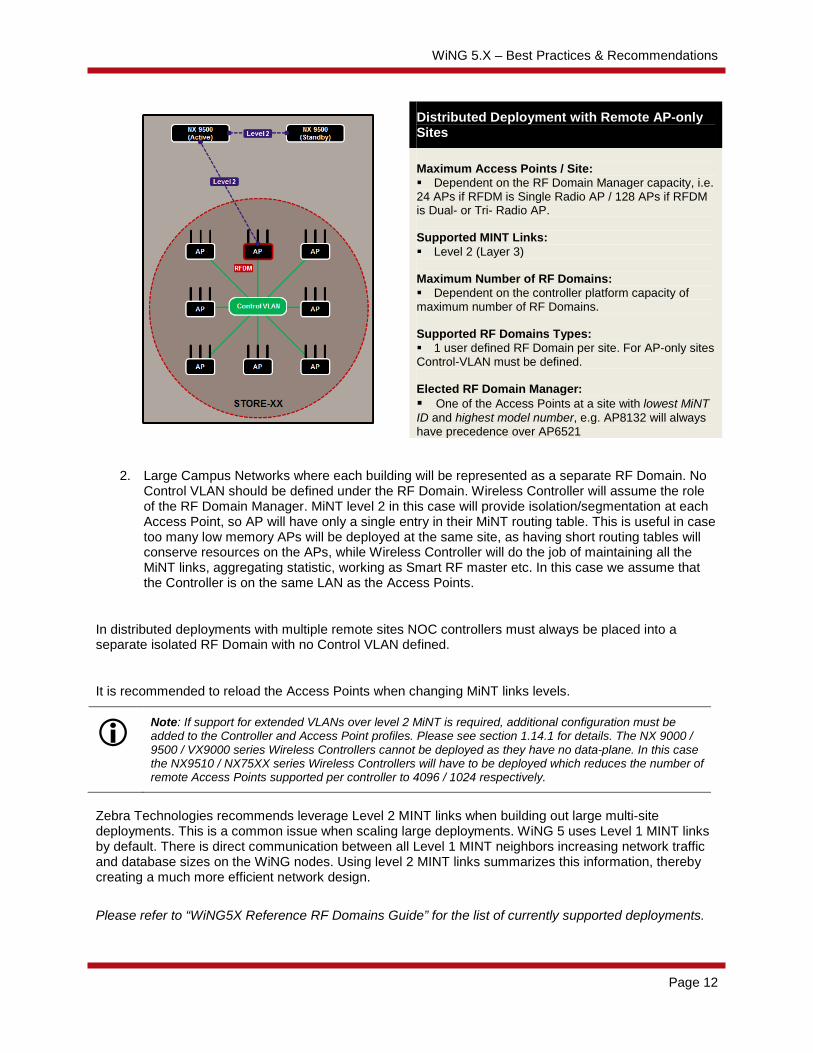
2. Large Campus Networks where each building will be represented as a separate RF Domain. No Control VLAN should be defined under the RF Domain. Wireless Controller will assume the role of the RF Domain Manager. MiNT level 2 in this case will provide isolation/segmentation at each Access Point, so AP will have only a single entry in their MiNT routing table. This is useful in case too many low memory APs will be deployed at the same site, as having short routing tables will conserve resources on the APs, while Wireless Controller will do the job of maintaining all the MiNT links, aggregating statistic, working as Smart RF master etc. In this case we assume that the Controller is on the same LAN as the Access Points.
In distributed deployments with multiple remote sites NOC controllers must always be placed into a separate isolated RF Domain with no Control VLAN defined.
It is recommended to reload the Access Points when changing MiNT links levels.
Note: If support for extended VLANs over level 2 MiNT is required, additional configuration must be added to the Controller and Access Point profiles. Please see section 1.14.1 for details. The NX 9000 / 9500 / VX9000 series Wireless Controllers cannot be deployed as they have no data-plane. In this case the NX9510 / NX75XX series Wireless Controllers will have to be deployed which reduces the number of remote Access Points supported per controller to 4096 / 1024 respectively.
Zebra Technologies recommends leverage Level 2 MINT links when building out large multi-site deployments. This is a common issue when scaling large deployments. WiNG 5 uses Level 1 MINT links by default. There is direct communication between all Level 1 MINT neighbors increasing network traffic and database sizes on the WiNG nodes. Using level 2 MINT links summarizes this information, thereby creating a much more efficient network design.
Please refer to “WiNG5X Reference RF Domains Guide” for the list of currently supported deployments.
Distributed Deployment with Remote AP-only Sites Maximum Access Points / Site: Dependent on the RF Domain Manager capacity, i.e. 24 APs if RFDM is Single Radio AP / 128 APs if RFDM is Dual- or Tri- Radio AP. Supported MINT Links: Level 2 (Layer 3) Maximum Number of RF Domains: Dependent on the controller platform capacity of maximum number of RF Domains. Supported RF Domains Types: 1 user defined RF Domain per site. For AP-only sites Control-VLAN must be defined. Elected RF Domain Manager: One of the Access Points at a site with lowest MiNT ID and highest model number, e.g. AP8132 will always have precedence over AP6521

WiNG 5.X – Best Practices & Recommendations
Page 13
1.4.3.1 Hierarchical Management - ONEVIEW. In Hierarchical Management type of deployment it is possible to have a mix of AP-only sites as well as larger sites with local Site Controllers. This is supported starting from WiNG 5.5 onwards. For those larger sites APs at the remote site will adopt to their respective Site Controllers via MiNT level 1 links, while Site Controllers will be adopted by the NOC controllers via MiNT level 2.
In such scenario local APs must be placed into the same RF Domain as the Site Controller and use VLAN or IP based MiNT level 1 links for adoption. One of the Site Controllers will act as an RF Domain manager for that site and will have a MiNT level 2 link established back to the NOC controller.
Please note that Control-Vlan must not be defined under the RF domain with Site Controllers.
Note: Site Controllers cannot control more than 1 RF domain, as well as APs cannot utilize MiNT level 2 links to be adopted to the Site Controller. Using unique Cluster names for each Site Controllers pair is required in ONEVIEW deployment.
1.1.9 Control VLAN vs. Controller VLAN The Control VLAN defines the VLAN id which is used by Access Points at a site to communicate statistics and other RF Domain related information with the elected RF Domain Manager at the site. The Controller VLAN defines the preferred VLAN id the Access Point uses to communicate with the Wireless Controller for adoption purposes.
The Control VLAN definition under the RF Domain is required only for distributed deployments using level 2 MINT links where the Access Points at a remote site discover each-other, elect an RF Domain Manager and perform functions such as Smart RF locally. Having a Control VLAN requires that all the APs at the site have one common broadcast domain, otherwise they will fail to properly elect the RF Domain manager, causing issues with adoption, roaming, getting statistics etc.
RF Domain Example:
!
rf-domain store100
location JohnsonCityTN
timezone EST5EDT
country-code us
use smart-rf-policy <smart-rf-policy-name>
control-vlan 11

WiNG 5.X – Best Practices & Recommendations
Page 14
!
For campus based deployments the Wireless Controller will be the elected RF Domain Manager and the Access Points will have level 1 MINT links to the Wireless Controller. As such Control VLAN configuration should not be used for this kind of deployments.
The Controller VLAN configuration is required only if Access Points and Controllers share more than one common VLAN (i.e. Access Points can reach the Wireless Controllers over multiple VLANs) and APs are adopted over Layer 2 using VLAN MINT links. In such deployments the Controller VLAN parameter can be defined in the Access Points profile to force the Access Points to form a level 1 MINT link to the Wireless Controllers using a specific VLAN id vs. selecting a random VLAN. Such deployment scenarios are rare hence the usage of Controller VLAN configuration is also rare.
Specified use-case above is the only occasion where controller VLAN is needed. Since Access Points and Controllers by default run MLCP over VLAN, they will establish VLAN based links automatically without any additional configuration. Controller VLAN in the Access Point profile will supersede any IP based adoption by creating a static VLAN MiNT link.
Access Point Profile Example:
!
profile ap6532 tmelabs-ap6532
ip name-server 192.168.10.10
ip domain-name tmelabs.local
ip default-gateway 192.168.11.1
autoinstall configuration
autoinstall firmware
interface radio1
wlan DOT1X bss 1 primary
wlan PSK bss 3 primary
wlan GUEST bss 4 primary
interface radio2
wlan DOT1X bss 1 primary
interface ge1
switchport mode trunk
switchport trunk native vlan 11
no switchport trunk native tagged
switchport trunk allowed vlan 11-14
ip dhcp trust
qos trust dscp
qos trust 802.1p
use firewall-policy default
use captive-portal server default
ntp server 192.168.10.10
logging on
controller vlan 11
service pm sys-restart
!

WiNG 5.X – Best Practices & Recommendations
Page 15
1.1.10 MiNT Level 1 Area-IDs In rare cases when Access Points on different RF Domains share one common broadcast domain might present a problem, since a common Control-VLAN across two sites will enable direct communication between devices over MiNT level 1. Example of such scenario would be a case where each RF Domain will represent one building in a Campus, but the management VLAN for Access Points will be the same across access switches in each building.
Although not a recommended practice to have such a design on the wired network, it is possible to separate Access Points or Controllers on the same Broadcast Domain using different MiNT Level 1 Area IDs. As such WiNG 5 devices with different Area IDs will not be able to communicate to each other and won’t form any MiNT links.
Access Point Profiles with different MiNT Level 1 Area ID Example:
!
profile ap7532 BUILDING-1
mint level 1 area-id 1
no autoinstall configuration
no autoinstall firmware
interface radio1
interface radio2
interface ge1
switchport mode trunk
switchport trunk native vlan 1
no switchport trunk native tagged
switchport trunk allowed vlan 1,10,20,70
interface vlan 1
ip address dhcp
ip dhcp client request options all
interface pppoe1
use firewall-policy default
service pm sys-restart
router ospf
!
profile ap7532 BUILDING-2
mint level 1 area-id 2
no autoinstall configuration
no autoinstall firmware
interface radio1
interface radio2
interface ge1
switchport mode trunk
switchport trunk native vlan 1
no switchport trunk native tagged

WiNG 5.X – Best Practices & Recommendations
Page 16
switchport trunk allowed vlan 1,10,20,70
interface vlan 1
ip address dhcp
ip dhcp client request options all
interface pppoe1
use firewall-policy default
service pm sys-restart
router ospf
!
rf-domain BUILDING-1
timezone CET
country-code de
use smart-rf-policy CAMPUS-SMART-RF
control-vlan 1
!
rf-domain BUILDING-2
timezone CET
country-code de
use smart-rf-policy CAMPUS-SMART-RF
control-vlan 1
!
1.1.11 Low Bandwidth High Latency WAN links In case any low bandwidth WAN links are present between the remote sites with high latency and packet loss, it is recommended to increase the default MiNT Hello Interval and Adjacency Hold Timer on both AP and Controller Profile. Usually hello interval value of 60 with adjacency hold-time of 180 should suffice on high latency links, but in some rare cases it may be extended to 120 hello interval and 360 adjacency hold-time.
Access Point Profile Example:
!
profile ap7532 default-ap7532
autoinstall configuration
autoinstall firmware
crypto ikev1 policy ikev1-default
isakmp-proposal default encryption aes-256 group 2 hash sha
crypto ikev2 policy ikev2-default
isakmp-proposal default encryption aes-256 group 2 hash sha
crypto ipsec transform-set default esp-aes-256 esp-sha-hmac
crypto ikev1 remote-vpn
crypto ikev2 remote-vpn

WiNG 5.X – Best Practices & Recommendations
Page 17
crypto auto-ipsec-secure
crypto load-management
crypto remote-vpn-client
interface radio1
interface radio2
interface ge1
interface vlan1
ip address dhcp
ip address zeroconf secondary
ip dhcp client request options all
interface pppoe1
use firewall-policy default
use client-identity-group default
controller hello-interval 60 adjacency-hold-time 180
service pm sys-restart
router ospf
!
1.2 Profile vs Device Overrides configuration In WiNG 5 device override level configuration always supersedes configuration done at the profile level. As a best practice it is highly recommended to keep most of the configuration as part of the profile, instead of device overrides. Device Overrides should be used only in cases unique configuration must be provisioned to a particular device, for example configuration such as hostname or static IP address, clustering etc. Rest of the objects that are common to a certain group of devices should always be assigned as part of the profile.
1.3 SNMP Polling Recommendations Several things to remember when working with WiNG 5 and any SNMP based management / monitoring tool. This applies for Air Defense Security Platform, as it is using SNMP as a primary protocol to poll network infrastructure devices:
1. SNMP Timeout – By default ADSP is using sub second timeout for SNMP responses. Depending on the size of the wireless network – we recommend increasing that number to 10 seconds.
2. Poll Interval – We recommend setting poll interval to at least 30 minutes as a minimum value. Lower intervals are too short to walk the whole table and will overload the Wireless Controller with too many SNMP requests. If polling a controller with thousands of access points, poll interval should be set down to at least 24 hours.
When using Wireless Controllers we recommend that you configure your SNMP monitoring tool to only poll the Wireless Controllers. It is not recommended that you poll the Access Points directly using WiNG-MIB OIDs. The Wireless Controllers have all the required information and statistics so there is no need to query each Access Point individually.
Additionally it is recommended that you defined separate management policies for the Wireless Controllers and Access Points. SNMP should be enabled in the management policy servicing the Wireless Controllers and disabled in the management policy servicing the Access Points. Remember to assign the management policies to the Wireless Controller and Access Point profiles.
WiNG 5.X – Best Practices & Recommendations
Page 18
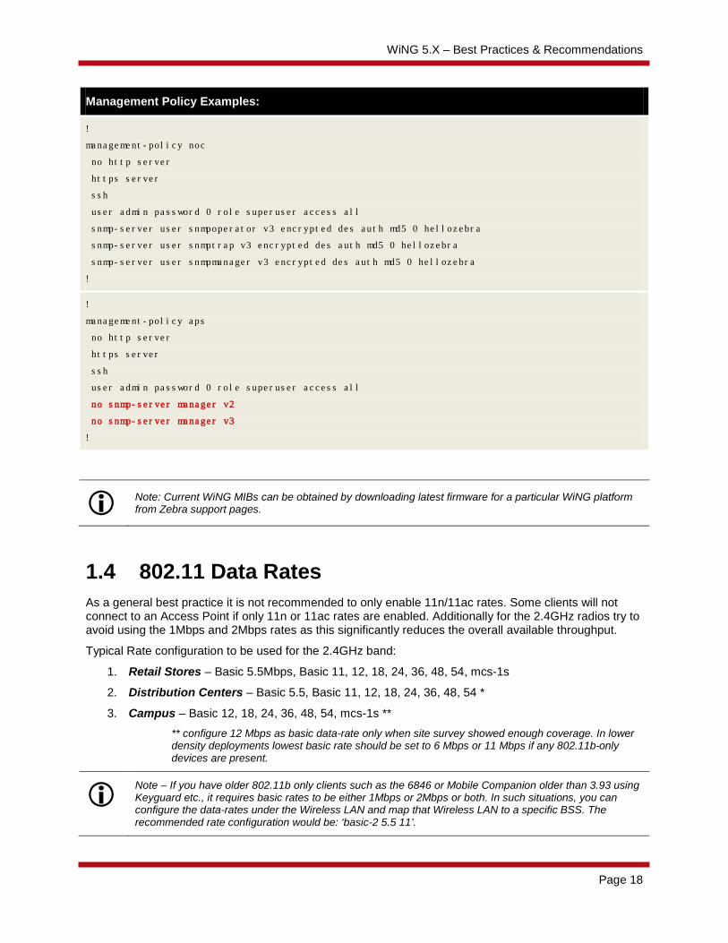
Management Policy Examples:
!
management-policy noc
no http server
https server
ssh
user admin password 0 role superuser access all
snmp-server user snmpoperator v3 encrypted des auth md5 0 hellozebra
snmp-server user snmptrap v3 encrypted des auth md5 0 hellozebra
snmp-server user snmpmanager v3 encrypted des auth md5 0 hellozebra
!
!
management-policy aps
no http server
https server
ssh
user admin password 0 role superuser access all
no snmp-server manager v2
no snmp-server manager v3
!
Note: Current WiNG MIBs can be obtained by downloading latest firmware for a particular WiNG platform from Zebra support pages.
1.4 802.11 Data Rates As a general best practice it is not recommended to only enable 11n/11ac rates. Some clients will not connect to an Access Point if only 11n or 11ac rates are enabled. Additionally for the 2.4GHz radios try to avoid using the 1Mbps and 2Mbps rates as this significantly reduces the overall available throughput.
Typical Rate configuration to be used for the 2.4GHz band:
1. Retail Stores – Basic 5.5Mbps, Basic 11, 12, 18, 24, 36, 48, 54, mcs-1s
2. Distribution Centers – Basic 5.5, Basic 11, 12, 18, 24, 36, 48, 54 *
3. Campus – Basic 12, 18, 24, 36, 48, 54, mcs-1s ** ** configure 12 Mbps as basic data-rate only when site survey showed enough coverage. In lower density deployments lowest basic rate should be set to 6 Mbps or 11 Mbps if any 802.11b-only devices are present.
Note – If you have older 802.11b only clients such as the 6846 or Mobile Companion older than 3.93 using Keyguard etc., it requires basic rates to be either 1Mbps or 2Mbps or both. In such situations, you can configure the data-rates under the Wireless LAN and map that Wireless LAN to a specific BSS. The recommended rate configuration would be: ‘basic-2 5.5 11’.
WiNG 5.X – Best Practices & Recommendations
Page 19
* It has been identified that Zebra ENC devices with Jedi radios can have connectivity issues when 5.5 and 11 Mbps data rates configured on infrastructure. If there are no 802.11b devices on the SSID / band, it is recommended to set data-rates to “gn”, “g-only” or custom rates with 5.5 and 11 Mbps rates excluded from supported rates. If 802.11b devices are present as well, recommendation is to set custom rates with 1 and 2 Mbps set as basic rates and exclude 5.5 and 11 Mbps from supported rates. This is client side issue and it is not specific to WING infrastructure. Devices impacted: MC17, MC5590, MC759X, MC75A, MC9590, MC3190, MC9190, VC609X, MT2090, MK3900, MK4900, MK590.
Typical Rate configuration to be used for 5GHz band:
1. Typical Deployments – The default data-rate configuration is ideal.
2. High-Density Access Point Deployments – Basic 12, 18, Basic 24, 36, 48, 54, mcs-1s, mcs-2s, mcs-3s
3. VoIP Deployments – Basic 12, 18, Basic 24, 36, 48, 54, mcs-1s * * configuring 12 Mbps as lowest basic data-rate should assume that enough coverage is in place. In lower density deployments lowest basic rate should be set to 6 Mbps.
Note – When using lower power devices like tablets and smart phones it is recommended not to set basic rates above 24Mbps.
Another feature in WiNG 5 is to allow probe responses to be sent at a rate different than what the probe request is received. The configuration is under the radio configuration inside an Access Point profile. It is recommended to use the probe-response rate lowest-basic as the configuration as it will dynamically choose the rates depending on the data rate configuration.
1.5 Antenna Diversity When using 802.11n/802.11ac Access Points and clients it is not recommended to configure antenna diversity. 802.11n/11ac already has a provision for diversity so enabling diversity will affect 802.11n transmissions.
1.6 Broadcast SSID vs. Answer Broadcast Probes WING 5 supports the ability to enable / disable broadcast SSID and answer broadcast probes. These parameters are enabled / disabled per Wireless LAN:
1. Broadcast SSID – If enabled the Access Point radios includes the ESSID in the beacon. If disabled the Access Point omits the ESSID from the beacon. When beacon doesn’t include the ESSID mobile clients usually send probes on to the air to find suitable Access Points. Therefore overall broadcast traffic is increased thus reducing total available airtime. When performance is an issue we don’t recommend disabling the ESSID in the beacon.
2. Answer Broadcast Probes – If enabled the Access Point will send a probe-response when a wireless client sends a broadcast probe. A lot of clients even if configured for specific ESSID will still send broadcast probes (i.e. probe requests with no ESSID). This will cause the Access Point to respond on each BSS where Wireless LAN is set to answer broadcast probes. When

WiNG 5.X – Best Practices & Recommendations
Page 20
performance is an issue we recommend disabling the feature and don’t answer broadcast probes. The usual case where answering broadcast probes might needed guest access (i.e. captive portal).
In most cases, if broadcast SSID is enabled (i.e. the ESSID is advertised in the beacon) you can safely disable answer broadcast probes. It is recommended to disable answer broadcast probes as it helps reducing probe responses going out from Access Points at lower data rates for all probes sent out by client devices (including devices that are not part of the customer network).
For Apple and Android devices like tablets, smart-phones and PDAs, it is recommended that broadcast SSID be enabled as the broadcasting of the SSID in the beacon is a requirement on these devices for roaming to be reliable.
1.7 Captive Portal 1.7.1 Captive Portal Service
One common mistake with Captive Portal deployments is to not assign the Captive Portal service to the device(s) that are providing the capture and redirection or assigning the Captive Portal service to the wrong device:
1. When the Captive Portal is operating on one or more Access Points at a site, the Captive Portal service must be assigned to the Access Points Profile or to individual Access Points as Overrides.
2. When the Captive Portal service is operating on one or more centralized Wireless Controllers, the Captive Portal service must be assigned to the Wireless Controllers Profile or to individual Wireless Controllers as Overrides.
When centralized-controller mode is enabled, ensure that both the Wireless Controllers have the Captive Portal service enabled.
Wireless Controller Profile Example:
!
profile rfs6000 tmelabs-rfs7000
ip name-server 192.168.10.6
ip domain-name tmelabs.local
!
!
!
use management-policy tmelabs
use firewall-policy default
use auto-provisioning-policy tmelabs
use captive-portal server <captive-portal-policy-name>
ntp server 192.168.10.6
no auto-learn-staging-config
service pm sys-restart
!

WiNG 5.X – Best Practices & Recommendations
Page 21
1.7.2 Firewall Policy The layer 3 firewall must be enabled on the Access Points for the capture and redirection to function. If the layer 3 firewall is disabled, the captive portal will not work. The layer 2 stateful packet inspection firewall can however be disabled if required.
Firewall Policy Example:
!
firewall-policy default
no stateful-packet-inspection-l2
!
1.7.3 Firewall Rules When firewall rules are assigned to the Captive Portal enabled Wireless LAN, the firewall policies need to permit TCP port 880 or 443 for the Captive Portal to function. By default a Captive Portal operating in HTTP mode will use TCP port 880 while a Captive Portal operating in HTTPS mode will use TCP 443. In addition ensure that DHCP, DNS and other required ports are permitted.
IP Access Control List Example:
!
ip access-list guests
permit tcp any host 192.168.20.22 eq 880 rule-precedence 20
permit tcp any host 192.168.20.23 eq 880 rule-precedence 21
permit tcp any host 1.1.1.1 eq 880 rule-precedence 22
permit udp any any eq dns rule-precedence 30
permit udp any eq 68 any eq dhcps rule-precedence 31
permit tcp any any eq www rule-precedence 32
permit tcp any any eq https rule-precedence 33
deny ip any any log rule-precedence 100
!
Note that in case Captive Portal service is running directly on the Access Point (self mode) redirection happens to a virtual IP address of 1.1.1.1.
If no firewall rules are applied, by default for non-authenticated users the Wireless Controller or Access Points will only permit DHCP, DNS and traffic destined to the Captive Portal service. Once authenticated the Captive Portal users will be provided full access to the network.

WiNG 5.X – Best Practices & Recommendations
Page 22
1.7.4 Captive Portal Server Cluster Failover It’s recommended to use the captive portal centralized-controller mode when using with cluster of Wireless Controllers. This provides failover in the event of a primary Wireless Controller failure. When using the centralized-controller mode you must enter a complete FQDN. The hostname must be a unique value that is unresolvable from DNS.
Captive Portal Policy Example:
!
captive-portal tmelabs-guests
server host portal.tmelabs.local
server mode centralized-controller
use aaa-policy internal-aaa
!
1.7.5 Externally Hosted Pages When configuring external web-pages the complete URL for each externally hosted page must be defined. In addition a DNS whitelist policy will also need to be created and assigned to the Captive Portal policy which includes webserver’s IP address or fully qualified domain name (FQDN). Failure to create and assign a DNS whitelist policy will result in the wireless users not being able to reach the external webserver.
Note – For DNS whitelist to function DNS ALG must be enabled in the firewall configuration.
DNS Whitelist & Captive Portal Policy Examples:
!
dns-whitelist tmelabs-guests
permit www.example.com
!

WiNG 5.X – Best Practices & Recommendations
Page 23
!
captive-portal tmelabs-guests
server host portal.tmelabs.local
server mode centralized-controller
webpage-location external
webpage external login http://www.example.com /<login-page-name>
webpage external welcome http://www.example.com/<welcome-page-name>
webpage external fail http://www.example.com/fail-page-name>
use aaa-policy internal-aaa
use dns-whitelist tmelabs-guests
!
1.7.6 Customizing Pages When customizing the agreement, failed, login and welcome pages it is important to include the necessary java scripting from the default pages. When creating customized pages it is recommended that you use the default pages as a reference:
1. First create a Captive Portal policy using the default parameters. Make sure the operating mode (i.e. HTTP or HTTPS) is set to match how you plan on implementing the Captive Portal.
2. Assign the Captive Portal policy to the Wireless Controller. This will create a copy of the default pages on the Wireless Controller which are located in the flash:/hostspot/<captive-portal-name> directory.
3. Copy the default pages to an external TFTP or FTP server.
4. For each customized page ensure the appropriate java scripts are included. Java scripts will be located at the top and bottom of some pages.
When hosting the customized login pages on a Wireless Controller or Access Point, ensure the web-page location is set to Advanced. Otherwise the customized login pages will be overwritten by the default pages when any changes are made to the Captive Portal policy.
Note: Captive portal query string delimiter has been changed to ‘&’ instead of ‘?’ from WiNG 5.5 onwards. When upgrading to a 5.5.x based firmware or higher, the JavaScript embedded in the external or advanced webpage(s) needs to be updated to parse the new style of query stings. Following line needs to be modified under function getQueryVariable(variable), var vars = query.split("?"); === change it to var vars = query.split(/[?&]/);
Please ensure that this function gets updated in all the captive portal pages that use it.
1.7.7 “No service” page for captive portal By default the failure page is only displayed if the Access Point (or Wireless Client) can reach a DNS server. Starting WING 5.5.5 addresses the issue with DNS reachability and provides option to configure service monitor dns crm <crm-name> vlan <failover-vlan>.
DNS Critical Resource Monitoring for No Service Page:

WiNG 5.X – Best Practices & Recommendations
Page 24
!
profile ap81xx Branch-1
no mint mlcp vlan
ip name-server 192.168.10.5
ip domain-name lab.local
!
! Configruation Removed for Brevity
!
interface radio1
wlan GUEST bss 1 primary
interface radio2
wlan GUEST bss 1 primary
interface radio3
!
! Configuration removed for Brevity
!
critical-resource DNS monitor direct any sync-adoptees 192.168.10.5
!
!
wlan GUEST
ssid GUEST
vlan 10
bridging-mode local
encryption-type none
authentication-type none
use captive-portal CPATH
captive-portal-enforcement fall-back
service monitor dns crm DNS vlan 10
!
This service command will monitor DNS server reachability. When DNS server is not reachable, the clients are moved to failover-vlan. In the failover-vlan every time DNS request comes from captive portal clients, they are redirected to no-service page since DNS server is not reachable. No-service page must always be an internal page either on the Access Point or Wireless Controller. In case of an extended VLAN, CRM for service monitor should be configured on the controller with sync-adoptees option under critical resource configuration. Any CRM state changes would be forwarded to the adopted devices which would redirect the wireless clients on the WLAN to no-service page in case the monitored CRM is down.

WiNG 5.X – Best Practices & Recommendations
Page 25
1.8 Clustering
1.8.1 Access Point Failover & Recovery By default in an Active / Standby cluster environment during an Active Controller failure, the Access Points will stay adopted to the Standby Controller after the Active Controller has recovered. Reverting the Access Points requires the Access Points to be manually un-adopted using the no adoption command on the Standby Controller.
Automatic reversion of the Access Points to the Active Controller can be optionally enabled by defining the cluster force-configured-state and cluster force-configured-state-delay <time-in-mins> parameters in the Controller Profiles or directly on the Controllers device configuration as Overrides. It is recommended however that the cluster force-configured-state-delay value be set to a conservative value to prevent flapping in the event that the Active Controller is repeatedly loosing connectivity or goes offline.
1.8.2 MINT Levels and Cluster Modes When defining a cluster of Wireless Controllers, all members of the cluster MUST be configured to use the same MINT level. Do not define cluster members at different MINT levels! Select level 1 or level 2 depending on your specific deployment:
1. For campus based local deployments the cluster should be formed using level 1 MINT links. Cluster mode may be Active/Active for load-balancing or Active/Stanby for redundancy. Active/Standby is preferred.
2. For distributed deployments over a WAN (locally bridged or tunneled VLANs), the cluster must be formed using level 2 MINT links. Only Active/Standby cluster mode is supported with this kind of deployments.
As a best practice avoid using VLAN based MiNT links to form a cluster and utilize IP based MiNT links instead. Mixing VLAN and IP based links for clustering is not supported and will pollute MiNT routing tables causing adoption, stability and clustering issues.
1.8.3 Cluster Failover When using tunneled VLANs and clustering it is recommended that the cluster communication / Access Point adoption and user VLANs NOT be assigned to different physical ports on the Wireless Controllers (i.e. Access Point adoption, cluster communications and management VLANs on Ge1 and extended VLANs on Ge2).
To prevent network loops only one Wireless Controller can be designated as the EVIS to forward tunneled VLAN traffic onto the wired network at a time. The Wireless Controllers are able to see each other (in most cases) over the tunneled VLANs and the alternative Wireless Controller will not take the EVIS role as long as it can see the first Wireless Controller over the tunneled VLAN(s).
If the cluster communication and tunneled VLANs are split between ports on the Wireless Controller you can run into issues during cluster failure scenarios. For example during normal operation the primary Wireless Controller adopts the Access Points and is the EVIS for the tunneled WLANs. A network failure disables communications on the Ge port on the primary Wireless Controller where the Access Point adoption, cluster and management VLANs reside.

WiNG 5.X – Best Practices & Recommendations
Page 26
The cluster protocol will go down and the Access Points will failover to the alternate Wireless Controller, however as the Wireless Controllers can still see each other over the tunneled VLANs the EVIS will not failover. The wireless user traffic will still be forwarded to the primary Wireless Controller which may not have access to the backbone.
As a best practice for clustering and failover it is recommended that:
1. All VLANs (Access Point adoption, cluster, management and user VLANs) be assigned to a common physical port on each Wireless Controller.
2. If additional capacity or availability is required it is recommended that 802.3ad static Link Aggregation (i.e. Port Channel) be enabled with all the VLANs (Access Point adoption, cluster, management and user VLANs) assigned as members of the Link Aggregation Group (LAG).
1.9 Naming Conventions When creating objects such as RF Domains, Profiles, Policies and ACLs within the Web-UI, it is strongly recommended that no spaces are used to name the objects. Using spaces adds control characters to the object name in the configuration which can be difficult to decipher and can cause errors in the configuration or operation of the system. As an alternative it is recommended that you use hyphens or underscore characters which will result in a cleaner configuration.
Note: When defining Hostnames of any WiNG device (APs or Controllers) in either GUI or CLI, please do not use underscore character, as this is not permitted by RFC and may cause adoption and stability issues, use hyphen as an alternative. Allowed characters are 0-9, a-z and a hyphen ‘-‘.

WiNG 5.X – Best Practices & Recommendations
Page 27
1.10 Smart-RF 1.10.1 Calibration
Running Smart-RF calibration manually is not recommended in WiNG 5. During normal operation it is recommended that you allow Smart-RF to converge on its own. If you need to re-run Smart-RF in an an environment where Smart-RF is already running use the service smart-rf clear-config command. It will take 5 to 10 minutes for Smart-RF to re-converge and assign the new channel and transmit power values.
Clearing Smart-RF Configuration Example:
RFSX000# service smart-rf clear-config
1.10.2 Channels and TX Power Assignments WiNG 5 allows Access Point channel and transmit power values to be assigned to Access Point radios using static configuration or Smart-RF. Zebra Technologies recommends using Smart-RF whenever possible.
The following is a list of recommendations for optimum Channel and Transmit Power assignments:
1. The use of Smart-RF requires that a Smart-RF Policy be assigned to each RF Domain. By default Access Points will use ACS (Automatic Channel Selection) and maximum transmit power which should be avoided.
2. The minimum transmit power range needs to be defined based on a physical site survey. By default the minimum transmit power is 4 and for a lot of sites this will not be an ideal value. For denser deployments minimum/maximum values will usually be configured as 8/11 dBm or 11/14 dBm respectively. For low density environments it may be beneficial to set the power statically to 17dBm and keep channel selection to smart.
3. The Access Point radios should also not be assigned the maximum transmit power. If the Access Point radios are operating at maximum power, Smart-RF will have no room to perform recovery operations.
4. By default Smart-RF will use all the available regulatory channels based on the assigned country code. For 5GHz operation it is recommended that you select a channel-list that does not include DFS channels whenever possible.
5. If Access Points are assigned to different Floors and / or Areas it is recommended to use Smart-RF grouping based on areas or floors. Usually only grouping by floor will be required indoors, while grouping by area will be used outdoors.
Note – For retail distribution center type deployments, the ideal minimum value for Smart-RF power is typically 8dBm. For retail store deployments (especially with high Access Point density), the default minimum power value (4dBm) is not ideal.

WiNG 5.X – Best Practices & Recommendations
Page 28
1.10.3 Coverage Hole Recovery The coverage hole recovery feature is required only for deployments where Access Point density/overlap is not optimal and there could be potential coverage holes in the network. In most cases these situations arise when customers perform a one for one Access Point replacement from a legacy low density 802.11b or 802.11bg deployments.
If the client density is high, it is recommended that you increase the coverage hole recovery client threshold. Using the default values will initiate coverage hole recovery if one client is below the SNR threshold.
For greenfield or new replacements performed using a site survey with -65dBm or -70dBm coverage requirement with 15 to 20% overlap, the coverage hole recovery feature is not required. If enabled it should be configured with a client threshold of 3 to 5 clients.
1.10.4 Smart Off Channel Scanning (OCS) For retail deployments with handheld devices using terminal emulation applications such as wave-link, it is recommended to use the smart-ocs-monitoring <band> power-save-aware strict mode.
Please be aware that setting Power-Save-Aware checks to strict will prevent radio to perform off channel scan when any client with Power Save enabled is associated (which means almost any client today, since most of them have some sort of PS enabled by default). It is possible to configure awareness-override to ignore those checks at either specified time slot/day of the week:
Smart-RF Smart Off Channel Scanning Example:
RFS6000(config-smart-rf-policy-default)# smart-ocs-monitoring power-save-aware 2.4GHz strict
Smart-RF Smart Off Channel Scanning Awareness Override example:
RFS6000(config-smart-rf-policy-default)# smart-ocs-monitoring awareness-override schedule 1 00:00 06:00 sat,sun
1.10.5 Example Smart-RF Policy The following are typical Smart-RF policies:
Typical Smart-RF Policy Example for Retail Store with US country code:
!
smart-rf-policy STORES
sensitivity custom
assignable-power 5GHz min 14
assignable-power 2.4GHz min 8
channel-list 5GHz 36,40,44,48,149,153,157,161,165
channel-width 5GHz 20MHz
smart-ocs-monitoring sample-count 5GHz 10

WiNG 5.X – Best Practices & Recommendations
Page 29
smart-ocs-monitoring sample-count 2.4GHz 15
smart-ocs-monitoring extended-scan-frequency 2.4GHz 0
coverage-hole-recovery snr-threshold 5GHz 10
coverage-hole-recovery snr-threshold 2.4GHz 10
neighbor-recovery dynamic-sampling
!
Typical Smart-RF Policy Example for lower density office and CAMPUS deployments:
!
smart-rf-policy CAMPUS
sensitivity custom
assignable-power 5GHz max 20
assignable-power 5GHz min 14
assignable-power 2.4GHz min 17
assignable-power 2.4GHz max 20
channel-list 5GHz 36,40,44,48,149,153,157,161,165
smart-ocs-monitoring sample-count 5GHz 10
smart-ocs-monitoring sample-count 2.4GHz 15
smart-ocs-monitoring extended-scan-frequency 2.4GHz 0
smart-ocs-monitoring awareness-override schedule 1 23:00 04:00 all
coverage-hole-recovery snr-threshold 5GHz 10
coverage-hole-recovery snr-threshold 2.4GHz 10
coverage-hole-recovery client-threshold 2.4GHz 3
neighbor-recovery dynamic-sampling
!
For additional tweaking of the Smart RF policy it is advised to export the smart rf report for a particular RF-domain, which will provide details on RF environment. CLI syntax to generate the report is:
Generate Smart RF Report example command syntax:
nx9500-1#remote-debug copy-smart-rf-report rf-domain BRANCH-1 write ftp://user:[email protected]/reports-folder/

WiNG 5.X – Best Practices & Recommendations
Page 30
1.11 Stateful Packet Inspection Firewall For a distribution center type environment with a lot of handheld devices and roaming, for application performance we would recommend disabling the layer 2 stateful packet inspection firewall:
Firewall Policy Example:
!
firewall-policy default
no stateful-packet-inspection-l2
!
The stateful packet inspection firewall has different knobs for different types of attacks. Each one can be enabled / disabled depending on customer needs and configuration.
Note that it is not recommended to disable proxy-arp as it helps reducing overall amount of Broadcast traffic on the network. It is enabled by default.
If the ip-mac conflict error is frequently seen and customer has verified that the DHCP servers are configured correctly on the network and same IP address isn’t provided to multiple host devices, it’s possible that ICMP redirects, routers running VRRP / HSRP or proxy devices on the network are causing the error. This can be remedied by applying following to firewall policy in use:
Firewall Policy Example:
!
firewall-policy default
no ip-mac conflict
no ip-mac routing conflict
!
If the service pktcap on drop command is showing packets are being dropped by a Wireless Controller or Access Point due to an IPSPOOF attack, the no ip dos command in the firewall policy servicing the affected devices will disable all DoS detection events:
Firewall Policy Example:
firewall-policy default
no ip dos smurf
no ip dos twinge
no ip dos invalid-protocol
!
! Configuration Removed for Brevity
!
!

WiNG 5.X – Best Practices & Recommendations
Page 31
Note: Disabling Firewall completely in WiNG 5 is not recommended and not supported, as most of the features require firewall to be on.
Recommended Firewall Policy Configuration:
!
firewall-policy default
no ip dos smurf
no ip dos twinge
no ip dos invalid-protocol
no ip dos router-advt
no ip dos router-solicit
no ip dos option-route
no ip dos ascend
no ip dos chargen
no ip dos fraggle
no ip dos snork
no ip dos ftp-bounce
no ip dos tcp-intercept
no ip dos broadcast-multicast-icmp
no ip dos land
no ip dos tcp-xmas-scan
no ip dos tcp-null-scan
no ip dos winnuke
no ip dos tcp-fin-scan
no ip dos udp-short-hdr
no ip dos tcp-post-syn
no ip dos tcphdrfrag
no ip dos ip-ttl-zero
no ip dos ipspoof
no ip dos tcp-bad-sequence
no ip dos tcp-sequence-past-window
no ip-mac conflict
no ip-mac routing conflict
dhcp-offer-convert
no stateful-packet-inspection-l2
!

WiNG 5.X – Best Practices & Recommendations
Page 32
1.12 Wireless Client Load Balancing Wireless client load-balancing is not enabled by default. It needs to be properly configured with full understanding of the exact needs and purpose for doing load-balancing.
There are two main ways to load-balance wireless clients:
1. Between Bands (Band Steering)
2. Between Access Points (Load-Balancing)
1.12.1 Band Steering Band steering allows dual-band capable wireless clients to be steered to a particular band (typically the 5GHz band). Configuring load-balancing to prefer the 2.4GHz band is generally not a requirement as most wireless clients will naturally prefer the 2.4GHz band over the 5GHz band. The primary use of band steering is in campus environments with dual band clients where it is desirable to have dual-band 802.11a/b/g/n/ac devices associate to the 5GHz band to free up the 2.4GHz band for legacy clients.
It is mandatory to have sufficient coverage on 5GHz band to use band steering. It is also recommended to lower transmit power on 2.4GHz band in order to provide better signal metrics for clients in 5GHz band.
To enable band steering to move dual-band capable clients will move to 5GHz band the following configuration needs to be performed on the Wireless LAN and Access Point profile(s):
5Ghz Band Steering Wireless LAN and Access Point Profile Example:
!
wlan LABS-DOT1X
ssid LABS-DOT1X
vlan 23
bridging-mode tunnel
encryption-type ccmp
authentication-type eap
client-load-balancing
use aaa-policy external-aaa
!
!
profile ap6532 tmelabs-ap6532
ip name-server 192.168.10.6
ip domain-name tmelabs.local
no autoinstall configuration
no autoinstall firmware
load-balancing balance-band-loads
interface radio1
wlan LABS-DOT1X bss 1 primary
interface radio2
wlan LABS-DOT1X bss 1 primary
!

WiNG 5.X – Best Practices & Recommendations
Page 33
1.12.2 Access Point Load Balancing The primary use of load-balancing between Access Points is for auditorium and stadium environments with a high concentration of wireless clients. Load balancing is required to distribute the wireless clients between the Access Point radios to reduce overloading a single Access Point. It’s also important to have a high Access Point density in the area where load-balancing is configured so wireless clients will have good signal connecting to any Access Point configured for load-balancing.
If load balancing needs to be configured in an auditorium it is mandatory that the load-balancing group-id parameter and value be defined in the Access Point profile servicing the Access Points in the auditorium. Load-balancing also needs to be enabled in the Wireless LANs to indicate with Wireless LANs support load-balancing.
1.13 Wireless LANs
Important: When mapping VLANs to Wireless LANs make sure that same VLAN is not configured for a tunneled and locally bridged WLAN. This is not a valid configuration. A VLAN’s bridging mode can either be tunnel or locally bridged but not both.
1.13.1 Default IP and MAC Access Lists It is always recommended to limit amount of Broadcast / Multicast traffic in the air. For this purpose default Access Lists can be utilized for each WLAN outbound direction. These ACLs will limit amount of unneeded broadcast/multicast traffic hitting the air. In case some multicast addresses must be allowed in the air (e.g. Video streaming or PTT), these ACLs may be adjusted according to the particular use-case:
Recommended WLAN ACL assignments:
!
ip access-list BROADCAST-MULTICAST-CONTROL
permit tcp any any rule-precedence 10 rule-description "permit all TCP traffic"
permit udp any eq 67 any eq dhcpc rule-precedence 11 rule-description "permit DHCP replies"
permit ip any 239.0.0.0/24 rule-precedence 19
deny udp any range 137 138 any range 137 138 rule-precedence 20 rule-description "deny windows netbios"
deny ip any 224.0.0.0/4 rule-precedence 21 rule-description "deny IP multicast"
deny ip any host 255.255.255.255 rule-precedence 22 rule-description "deny IP local broadcast"
permit ip any any rule-precedence 100 rule-description "permit all IP traffic"
!
mac access-list PERMIT-ARP-AND-IPv4
permit any any type ip rule-precedence 10 rule-description "permit all IPv4 traffic"
permit any any type arp rule-precedence 20 rule-description "permit all ARP traffic"
!
!
wlan DOT1X-CORP
ssid DOT1X-CORP
vlan 10
bridging-mode local

WiNG 5.X – Best Practices & Recommendations
Page 34
encryption-type ccmp
authentication-type eap
no answer-broadcast-probes
use aaa-policy extEAP
use ip-access-list out BROADCAST-MULTICAST-CONTROL
use mac-access-list out PERMIT-ARP-AND-IPv4
!
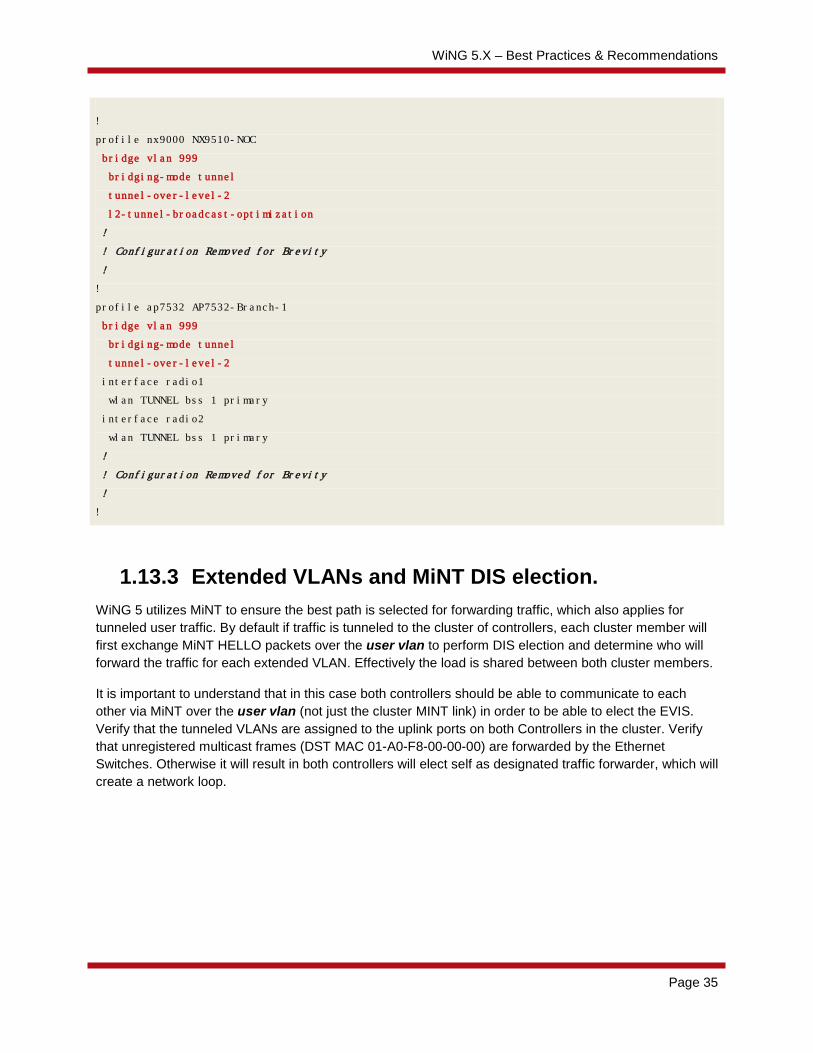
1.13.2 Tunneling over level 2 MINT links If there is a requirement to tunnel user traffic with distributed deployments where level 2 MiNT links are used, additional configuration must be in place on the Controller and Access Point Profile.
1. Wi-Fi user traffic is encapsulated and forwarded to the elected RF Domain Manager (RFDM) within the site using IP or VLAN based Level 1 MINT links.
2. Wi-Fi user traffic is re-encapsulated and forwarded by the RFDM to the Active Centralized Controller in the datacenter using an IP based Level 2 MINT link
Tunneling via MiNT Level 2 Configuration Example:
!
wlan TUNNEL
ssid TUNNEL
vlan 999
bridging-mode tunnel
encryption-type ccmp
authentication-type none
wpa-wpa2 psk 0 hellozebra
!
WiNG 5.X – Best Practices & Recommendations
Page 35
!
profile nx9000 NX9510-NOC
bridge vlan 999
bridging-mode tunnel
tunnel-over-level-2
l2-tunnel-broadcast-optimization
!
! Configuration Removed for Brevity
!
!
profile ap7532 AP7532-Branch-1
bridge vlan 999
bridging-mode tunnel
tunnel-over-level-2
interface radio1
wlan TUNNEL bss 1 primary
interface radio2
wlan TUNNEL bss 1 primary
!
! Configuration Removed for Brevity
!
!
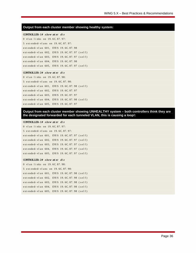
1.13.3 Extended VLANs and MiNT DIS election. WiNG 5 utilizes MiNT to ensure the best path is selected for forwarding traffic, which also applies for tunneled user traffic. By default if traffic is tunneled to the cluster of controllers, each cluster member will first exchange MiNT HELLO packets over the user vlan to perform DIS election and determine who will forward the traffic for each extended VLAN. Effectively the load is shared between both cluster members.
It is important to understand that in this case both controllers should be able to communicate to each other via MiNT over the user vlan (not just the cluster MINT link) in order to be able to elect the EVIS. Verify that the tunneled VLANs are assigned to the uplink ports on both Controllers in the cluster. Verify that unregistered multicast frames (DST MAC 01-A0-F8-00-00-00) are forwarded by the Ethernet Switches. Otherwise it will result in both controllers will elect self as designated traffic forwarder, which will create a network loop.
WiNG 5.X – Best Practices & Recommendations
Page 36
Output from each cluster member showing healthy system:
CONTROLLER-1# show mint dis
0 vlan links on 19.6C.87.97:
5 extended-vlans on 19.6C.87.97:
extended-vlan 601, EVIS 19.6C.87.98
extended-vlan 602, EVIS 19.6C.87.97 (self)
extended-vlan 603, EVIS 19.6C.87.97 (self)
extended-vlan 604, EVIS 19.6C.87.98
extended-vlan 605, EVIS 19.6C.87.97 (self)
CONTROLLER-2# show mint dis
0 vlan links on 19.6C.87.98:
5 extended-vlans on 19.6C.87.98:
extended-vlan 601, EVIS 19.6C.87.98 (self)
extended-vlan 602, EVIS 19.6C.87.97
extended-vlan 603, EVIS 19.6C.87.97
extended-vlan 604, EVIS 19.6C.87.98 (self)
extended-vlan 605, EVIS 19.6C.87.97
Output from each cluster member showing UNHEALTHY system – both controllers think they are the designated forwarded for each tunneled VLAN, this is causing a loop!:
CONTROLLER-1# show mint dis
0 vlan links on 19.6C.87.97:
5 extended-vlans on 19.6C.87.97:
extended-vlan 601, EVIS 19.6C.87.97 (self)
extended-vlan 602, EVIS 19.6C.87.97 (self)
extended-vlan 603, EVIS 19.6C.87.97 (self)
extended-vlan 604, EVIS 19.6C.87.97 (self)
extended-vlan 605, EVIS 19.6C.87.97 (self)
CONTROLLER-2# show mint dis
0 vlan links on 19.6C.87.98:
5 extended-vlans on 19.6C.87.98:
extended-vlan 601, EVIS 19.6C.87.98 (self)
extended-vlan 602, EVIS 19.6C.87.98 (self)
extended-vlan 603, EVIS 19.6C.87.98 (self)
extended-vlan 604, EVIS 19.6C.87.98 (self)
extended-vlan 605, EVIS 19.6C.87.98 (self)

WiNG 5.X – Best Practices & Recommendations
Page 37
1.13.4 L2TPv3 Tunneling Typical scenario when L2TPv3 tunnels are utilized in a distributed deployment is as follows:
1. Wi-Fi user traffic is encapsulated and forwarded to the elected RF Domain Manager (RFDM) within the site using IP or VLAN based Level 1 MINT links.
2. Wi-Fi user traffic is re-encapsulated and forwarded by the RFDM to the L2TPv3 concentrator in the datacenter using an L2TPv3 tunnel. In this case since NOC NX9500 controller does not have a dataplane, we have to tunnel to a dedicated RFS7000 cluster via L2TPv3.
Tunneling via L2TPv3 Configuration Example:
!
wlan L2TPv3-TUNNEL
ssid L2TPv3-TUNNEL
vlan 999
bridging-mode local
encryption-type ccmp
authentication-type none
wpa-wpa2 psk 0 hellozebra
!
!
profile nx9000 NX9500-NOC
!
! Configuration Removed for Brevity
!
!
profile rfs7000 RFS7K-L2TPv3-CONCENTRATOR

WiNG 5.X – Best Practices & Recommendations
Page 38
bridge vlan 999
l2-tunnel-broadcast-optimisation
!
! Configuration Removed for Brevity
!
l2tpv3 tunnel GUEST
peer 1 hostname any router-id any
session GUEST pseudowire-id 999 traffic-source vlan 999
establishment-criteria cluster-master
!
profile ap7532 AP7532-Branch-1
bridge vlan 999
bridging-mode tunnel
interface radio1
wlan TUNNEL bss 1 primary
interface radio2
wlan TUNNEL bss 1 primary
!
! Configuration Removed for Brevity
!
l2tpv3 tunnel GUEST
peer 1 ip-address 89.102.33.201 hostname any router-id any
peer 2 ip-address 89.102.33.202 hostname any router-id any
session GUEST pseudowire-id 999 traffic-source vlan 999
establishment-criteria rf-domain-manager
l2tpv3 inter-tunnel-bridging
!
WiNG 5.X – Best Practices & Recommendations
Page 39
1.13.5 L2TPv3 vs MiNT Level 2 Tunneling Currently there are two major methods of tunneling user traffic in large distributed deployments. There are certain use-cases to use L2TPv3 tunneling over MiNT level 2 tunneling and vice versa.
When to implement tunneling via MiNT level 2:
1. HM / Distributed deployments that use RFS 7000, NX 7500 or NX 9510 / 9610 as Centralized Controllers (i.e. have a data-plane).
2. HM / Distributed deployments that require the tunneled traffic to terminate on the Active Centralized Controller.
When to implement tunneling via L2TPv3:
1. HM / Distributed deployments that use NX 9500 / NX9600 as Centralized Controllers (i.e. no data-plane).
2. HM / Distributed deployments that require the tunneled traffic to be offloaded to an isolated part of the network such as a DMZ or POP (i.e. separate from the data center).
3. HM / Distributed deployments that wish to distribute tunneled traffic between multiple points in the network.

WiNG 5.X – Best Practices & Recommendations
Page 40
1.14 Wireless Mesh
1.14.1 Single Hop Mesh For Single Hop Mesh the Mesh VLAN needs to be extended for the Mesh to work. All Access Point members participating in Mesh network needs to have the following configured either in the Access Point profile or directly on the device as an override:
Mesh and User VLAN Bridging Example:
bridge vlan <vlan-id>
bridging-mode tunnel
Note – If you deploy a dedicate WLAN for Mesh; the bridging-mode in the WLAN does not have to be tunneled for Mesh to work.
If the Mesh network needs to forward all the Wireless user traffic to the Wireless Controller, do not assign the VLANs to the Access Points physical ports. The user VLANs only need to be assigned to a physical port on the Wireless Controller where the traffic is switched onto the wired network. Additionally like the Mesh VLAN, each user VLAN will need to be bridged using the Access Profile or device override.
Mesh WLAN, Access Point Profile and Device Override Example:
! Mesh Wireless LAN
wlan TMELABS-MESH
ssid TMELABS-MESH
vlan 21
bridging-mode local
encryption-type ccmp
authentication-type none
wpa-wpa2 psk 0 hellozebra
!
! User Wireless LAN
wlan TMELABS-DOT1X
ssid TMELABS-DOT1X
vlan 22
bridging-mode tunnel
encryption-type ccmp
authentication-type eap
use aaa-policy external-aaa
!

WiNG 5.X – Best Practices & Recommendations
Page 41
! Access Point Profile
profile ap6532 tmelabs-ap6532
bridge vlan 21
bridging-mode tunnel
ip igmp snooping
ip igmp snooping querier
bridge vlan 22
bridging-mode tunnel
ip igmp snooping
ip igmp snooping querier
ip name-server 192.168.10.6
ip domain-name tmelabs.local
no autoinstall configuration
no autoinstall firmware
interface radio1
wlan TMELABS-DOT1X bss 1 primary
interface radio2
wlan TMELABS-MESH bss 1 primary
interface ge1
description Uplink
switchport mode trunk
switchport trunk native vlan 21
no switchport trunk native tagged
switchport trunk allowed vlan 21-22
ip dhcp trust
qos trust dscp
qos trust 802.1p
interface vlan21
ip address dhcp
ip dhcp client request options all
use management-policy tmelabs
use firewall-policy default
ntp server 192.168.10.6
service pm sys-restart
!
! AP7131N Base Bridge
ap71xx 00-23-68-97-04-DC
use profile tmelabs-ap71xx
use rf-domain tmelabs
hostname ap7131-1-bb
interface radio2
channel 36+
power 1
mesh portal
mesh psk hellozebra

WiNG 5.X – Best Practices & Recommendations
Page 42
!
! AP7131N Client Bridge
ap71xx 00-23-68-99-B9-30
use profile tmelabs-ap71xx
use rf-domain tmelabs
hostname ap7131-2-cb
interface radio2
mesh client
mesh psk hellozebra
!
1.14.2 MeshConnex Configuration for Bridge Links Since Single Hop Mesh feature is considered legacy and will not be supported in our latest AP platforms, MeshConnex can be utilized to create simple bridge links.
Note that in case when MeshConnex is used for creating a bridge link it is recommended to extend the VLANs between the Root and Non-Root APs rather that add them into allowed VLANs list under Mesh Connex policy. This will provide better performance. Each VLAN that you need to pass through the MeshConnex link should be extended at the Root and the Non-Root AP. Extended VLANs must not be in the allowed-vlans list, otherwise it will cause a network loop.
Control-vlan can be any VLAN in case only 1 single Root AP will be present. Control-vlan under MeshConnex policy is only used for communication between Root APs.
Please note that by default Layer 2 MiNT traffic will not be passed through the MeshConnex link. In case adoption of Access Points behind MeshConnex link is required it is recommended to use IP based MiNT links.
Example configuration below is a typical scenario with a bridge link between 2 buildings where VLANs 10 and 20 needs to be passed across with MCX ACS configured for ETSI regulatory domain using outdoor 5GHz channels with lowest CAC:
Mesh WLAN, Access Point Profile and Device Override Example:
!
meshpoint BRIDGE
meshid BRIDGE
beacon-format mesh-point
control-vlan 50
allowed-vlans 50
security-mode psk
wpa2 psk 0 hellozebra
no root
!
! Access Point Profile
profile ap81xx bridge-APs
bridge vlan 10
bridging-mode tunnel

WiNG 5.X – Best Practices & Recommendations
Page 43
ip igmp snooping
ip igmp snooping querier
bridge vlan 20
bridging-mode tunnel
ip igmp snooping
ip igmp snooping querier
no mint mlcp vlan
ip name-server 192.168.10.5
ip domain-name lab.local
no autoinstall configuration
no autoinstall firmware
interface radio1
interface radio2
meshpoint BRIDGE bss 1
no dynamic-chain-selection
no dfs-rehome
rate-selection opportunistic
non-unicast tx-rate lowest-basic
interface radio3
interface ge1
switchport mode trunk
switchport trunk native vlan 50
no switchport trunk native tagged
switchport trunk allowed vlan 10,20,50
interface ge2
interface vlan50
ip address dhcp
ip dhcp client request options all
use firewall-policy default
meshpoint-device BRIDGE
root
path-method uniform
!
! RF Domain Configuration
rf-domain APs
timezone CET
country-code cz
channel-list dynamic
channel-list 5GHz 100,104,108,112,116,132,136,140
!
! AP8132 Base Bridge
ap81xx B4-C7-99-71-FC-F4
use profile bridge-APs
use rf-domain APs
WiNG 5.X – Best Practices & Recommendations
Page 44
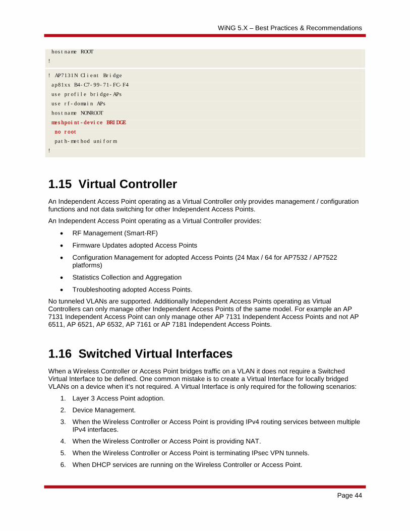
hostname ROOT
!
! AP7131N Client Bridge
ap81xx B4-C7-99-71-FC-F4
use profile bridge-APs
use rf-domain APs
hostname NONROOT
meshpoint-device BRIDGE
no root
path-method uniform
!
1.15 Virtual Controller An Independent Access Point operating as a Virtual Controller only provides management / configuration functions and not data switching for other Independent Access Points.
An Independent Access Point operating as a Virtual Controller provides:
• RF Management (Smart-RF)
• Firmware Updates adopted Access Points
• Configuration Management for adopted Access Points (24 Max / 64 for AP7532 / AP7522 platforms)
• Statistics Collection and Aggregation
• Troubleshooting adopted Access Points.
No tunneled VLANs are supported. Additionally Independent Access Points operating as Virtual Controllers can only manage other Independent Access Points of the same model. For example an AP 7131 Independent Access Point can only manage other AP 7131 Independent Access Points and not AP 6511, AP 6521, AP 6532, AP 7161 or AP 7181 Independent Access Points.
1.16 Switched Virtual Interfaces When a Wireless Controller or Access Point bridges traffic on a VLAN it does not require a Switched Virtual Interface to be defined. One common mistake is to create a Virtual Interface for locally bridged VLANs on a device when it’s not required. A Virtual Interface is only required for the following scenarios:
1. Layer 3 Access Point adoption.
2. Device Management.
3. When the Wireless Controller or Access Point is providing IPv4 routing services between multiple IPv4 interfaces.
4. When the Wireless Controller or Access Point is providing NAT.
5. When the Wireless Controller or Access Point is terminating IPsec VPN tunnels.
6. When DHCP services are running on the Wireless Controller or Access Point.

WiNG 5.X – Best Practices & Recommendations
Page 45
Please note that all routed IPv4 traffic is inspected by the stateful packet inspection firewall. When IPv4 routing doesn’t work as expected with the defined Virtual IP interfaces, issue a service pktcap on drop command to see if any packets are being dropped by the stateful packet inspection firewall. Most firewall checks are enabled by default and can be disabled if needed.
1.17 Zero Config IPv4 Address A Zero Config IPv4 address is assigned by default to new Access Points on VLAN 1 to provide a mechanism to configure the Access Points when no DHCP services are present on the network. It’s important to note that the Zero Config IPv4 address will only apply to VLAN 1 and will not work on any other VLAN.
If no DHCP services are present, each Access Point will be automatically configured with a Zero Config IPv4 Address 169.254.X.Y/16 where:
1. X = the decimal equivalent of the 5th octet of the MAC address
2. Y = the decimal equivalent of the 6th octet of the MAC address
The Zero Config IPv4 address for an Access Point can be determined by converting the 5th and 6th octets of the Access Points MAC address from HEX to Decimal. For example an Access Point with the MAC address 00-23-68-97-04-DC will use the Zero Config IPv4 Address 169.254.4.220.

WiNG 5.X – Best Practices & Recommendations
Page 46
1.18 Firmware Upgrades
1.18.1 Centrally Managed Environments When upgrading Access Points in large centrally managed distributed environments, it is recommended that the device-upgrade command be utilized to perform the upgrade. By default after a Controller is upgraded to a new release, the remote Access Points will individually download their new firmware upon re-adoption. The maximum number of simultaneous upgrades a Controller can support is 20.
To optimize WAN bandwidth and streamline the upgrade process for large centrally managed deployments it is recommended that:
1. Automatic AP upgrades be disabled on the Controller profile prior to reloading the Controllers with the new firmware release with command “no device-upgrade auto”
2. The device-upgrade command can be utilized to initiate the upgrade via the elected RF Domain Managers at each remote site.
3. Optionally device-upgrade command may be used in combination with either option no-reboot to prevent automatic reboot after upgrade or staggered-reboot to reboot APs one by one at the site to minimize the impact. However please note that staggered-reboot may take considerable amount of time as it reboots only one AP at a time and waits till this AP boots up and readopts.
4. Use reload on <RF DOMAIN> exclude-controllers command to reboot all APs at specific rf-domain, in case no-reboot option has been used during the device upgrade.
5. In MeshConnex deployments it is always recommended to upgrade Non-Root APs first, hence using device-upgrade rf-domain <RF DOMAIN> containing <name substring> will ensure that only APs containing specified string in the hostname will be upgraded.
Assuming proper naming is in place to distinguish between Root and Non-Root APs example below shows the syntax for this use-case:
nx9500-1#device-upgrade rf-domain remote-1 containing non-root
Using this methodology allows up to 20 x remote sites to be simultaneously upgraded vs. 20 x individual Access Points.
1.18.2 Clearing manually loaded device images from the Controller
In case network administrator had manually loaded any AP or controller image to the NOC controller via device-upgrade load-image command, those images will not be automatically cleared upon controller upgrade. They will be stored inside the flash:/upgrade/ directory and can be deleted if needed to free up flash storage via command syntax delete flash:/upgrade/<image name>.img, for example:
Deleting Previously Loaded Images on the Controller:
rfs4000-1#delete flash:/upgrade/khepri.img

WiNG 5.X – Best Practices & Recommendations
Page 47
1.18.3 Slow WAN Links When performing manual firmware upgrades over slow WAN links, it is recommended that you increase the idle-sessions-timeout parameter in the management policy to a higher value. By default the idle timeout value is set to 30 minutes and the telnet, SSH or HTTP(s) session may timeout if the manual firmware upgrade exceeds 30 minutes. Increasing this value allows the management session to be maintained for longer periods allowing a manual firmware upgrade to be completed.
Increasing the Idle Session Timeout Interval Example:
RFSX000(config-management-policy-<name># idle-session-timeout <value>
Please note that this parameter will only be applied to new telnet, SSH or HTTP(s) management sessions. Once this value is changed you will need to close your existing management session and restart a new management session.
1.19 Event System policies and SMTP notification. In WiNG5 by default newly created event system policy will have almost every event in each module set to value “default”, which in most cases is the same as “on”. For large deployments it is highly recommended to limit the number of modules and number of events per module to forward to the logging host, otherwise too many events coming from too many devices might overload the controller’s cfgd process, causing adoption and stability issues as a side effect.
Note – Starting from WiNG 5.5.6 onwards some events forwarding will be disabled by default. This will prevent situation when controller adopting many APs will receive too many events. Events for which forwarding to a controller will be disabled by default are: “dot11 client-associated”, “dot11 client-disassociated”, and “dot11 client-info”.
For the NOC controller it is recommended to start with disabling all events for each and every module in the GUI and then enable only those critical events that will be required. It is also advisable to create a separate Event System Policy for the APs and/or Site Controllers at remote sites to control which events are being forwarded back to the NOC controller.
For tracking adoption issues it is highly recommended to limit the events only for device offline events instead of device unadopted. Furthermore it is advised to limit events on the controller to device offline and critical messages from diag module like high CPU / memory usage, otherwise too many events at the NOC controllers with many APs adopted might put a heavy load on the system.

WiNG 5.X – Best Practices & Recommendations
Page 48
1.20 Migrating legacy installations to new 802.11n/802.11ac Access Points.
The following are industry best practices when migrating from any legacy installation to a new generation 802.11n/802.11ac Access Points:
1. Use the 5GHz radio for sensitive voice over WLAN applications.
The 2.4GHz ISM band is heavily used for non 802.11 RF that can prevent the 2.4GHz network from achieving the network latency and jitter requirements for voice applications. The result often is represented as poor voice quality or poor roaming performance. The underlying cause is radio transmission backoff as a result of RF noise on the same or adjacent channel. In any country or regulatory domain, the 5GHz band will provide significantly more non-overlapping channels than the 2.4GHz band. This ensures that non-adjacent and non-overlapping channels can be used to meet the latency and jitter requirements. If the desired voice application only runs on 2.4GHz band, use an AP with a three stream antenna system such as the AP 8132, or AP 7532.
2. Architect the solution for a high AP density.
Customers that are upgrading a network using the AP 300 or AP 5131 may assume that a newer AP will be a one-to-one replacement for the older technology. However, this is not the case. Over the years, regulatory bodies have adjusted the allowed limits for RF transmitters and the technology has undergone dramatic changes. A site survey will determine the actual AP density, but in general a newer 802.11n or 802.11ac. The target RSSI is -65dBm.
Usually in low density deployments we will be looking at 5000sqft / 460sqm coverage areas, while a bit denser deployment for 5GHz and higher data-rates will have roughly 3500-4000sqft / 325-371sqm. For high density deployments with locationing services approximate numbers would be ranging from 2500-3000sqft / 232-278sqm. Please note that these values are only approximate and a site survey is always recommended.
3. Conduct a thorough site survey of the RF environment.
A site survey will encompass three distinct phase:
1. Site scan. The site scan will determine the noise level and utilization across all channels in the band. Pick five locations around the environment and capture packets for at least five minutes on all channels and all bands for that location. Characterize the resulting noise in terms of average and peak utilization on each channel, received noise floor, number of stations and number of clients on each channel. Filter the site scan data so that the current network can be distinguished from the background RF signals. The new APs will need to support the current network and avoid contention from background RF signals.
2. Site Survey. Set the site survey software to only scan the channels that you are using during the site survey. Since the site survey software must dwell on each channel for approximately 200ms, scanning all possible channels will result in a significant reduction in the quality of the data. The output of the site survey is a heat map showing the AP signal levels (RSSI), and SNR.

WiNG 5.X – Best Practices & Recommendations
Page 49
Survey both 2.4GHz and 5GHz bands. Make sure to use more capture points to get reliable results from the Site Survey software.
3. Performance test. Once the site survey is done, locate the areas at the edges of the coverage and conduct performance tests using a device that will be typical in the use case. iPerf running on a wired client and running on a common tablet device may be an effective tool. The tested value will not match the maximum throughput of the AP, but will be accurate for the test environment and devices.
Note: always account for external antenna gain when doing a migration or a new installation. If migrating from legacy Access Points with external antennas to new Access Points with integrated antennas account for antenna gain. APs with Internal Antennas have antenna gain hardcoded in the software, so it will be automatically deducted during the EIRP calculation. Also when migrating from legacy 802.11a/b/g infrastructure note that new generation 802.11n/802.11ac Access Points also subtract MIMO gain (based on the number of transmit chains) when setting up power values.
1.21 CDP / LLDP By default each WiNG device runs CDP and LLDP protocols, which are designed to help mitigate some of the issues with the wired infrastructure. However it has been identified that in rare cases when customers have mixed switching infrastructure, for example mix of managed and unmanaged switches OR switches that understand both CDP and LLDP and switches that understand LLDP only - having CDP enabled might cause increased CPU load on the adopting controller. In such cases it is highly recommended to disable both CDP and LLDP on all AP profiles. You should also disable CDP even if you run managed switches that might not understand CDP protocol, such as for example Extreme or HP switches.
Disable CDP / LLDP on the AP profile:
!
profile ap7532 BRANCH-1
!
! Configuration removed for brevity
!
no cdp run
no lldp run
!
1.22 Virtualized Controller Platform Starting with WiNG 5.6 release new Virtualized Controller Platform – VX9000 – has been introduced. It is important to understand the advantages, as well as its limitations before deploying this kind of solution.
Since VX9000 platform does not have a dedicated dataplane, it is highly recommended not to use VX9000 to forward wireless client user traffic, either through MiNT from local APs to a Site Controller or via alternative methods, like L2TPv3 or L2oGRE tunnels.
Virtualized Platform provides scalability “On Demand”, i.e. CPU and Memory resources can be assigned based on the current requirement to support X number of Access Points.
Note: After the VX controller is licensed you must not change the IP address of the management SVI, since VX Serial Number is a combination of MAC and IP address.

WiNG 5.X – Best Practices & Recommendations
Page 50
1.23 3G/LTE Adapter for WWAN Some Wireless Controller and Access Point platforms support a PCI ExpressCard slot allowing a third-party 3G adapter to be installed. This allows the 3G service to be used for Internet access in addition to providing an alternative path to the corporate network in the event of a primary WAN or internet service provider failure.
Note –WiNG 5.5 included support for Sierra Wireless 313U LTE USB module for AP8132 and RFS40X0 platforms.
It is important to note that some wireless ISPs will terminate the connection if they receive packets whose source IPv4 address doesn’t match the ISP’s assigned client IPv4 address. Specifically Verizon has been found to do this. If the default gateway is pointed to the WWAN, the Wireless Controller or Access Point may route packets from other hosts out of the WWAN interface which will cause the ISP to disconnect the session.
There are two ways to resolve this:
1. If the desired default gateway is the wireless ISPs gateway, NAT must be enabled on the Wireless Controller / Access Point so that the source IPv4 address of the packets is the ISP assigned IPv4 address.
2. If NAT is disabled and IPsec VPN tunneling is enabled, the tunnel ACL defines which traffic is forwarded over the tunnel. Any traffic that misses the tunnel must be blocked by a separate ACL otherwise it will be forwarded to a gateway IPv4 address outside of the tunnel causing the ISP to disconnect.
2. Contacting Technical Support In case you should require technical support assistance, below is the basic list of information you should provide ahead to help technical support engineers address your issue as soon as possible. This list is not finite; it may be required to provide additional data depending on the particular case.
1. Serial Number or Service Contract number that will prove Entitlement to receive Technical Support from Zebra Technologies.
2. Techsupport dump from the affected WiNG devices, usually it is the main controller and/or APs where the issue is observed. Tehsupport dump contains current snapshot of the system at the moment it is taken, for example running and startup configuration, output from most of the “show” command, even history, log messages and crash info.
Syntax: remote-debug copy-techsupport hosts <Controller hostname> <AP hostname> write <URL>:
Example command to collect Techsupport dump from any WiNG device
vx9000-1>
vx9000-1>enable
vx9000-1#remote-debug copy-techsupport hosts vx9000-1 remote-AP-1 write ftp://ftpuser:[email protected]/folderForDumps/
For additional information on collecting relevant troubleshooting information please refer to WING 5.X How To Remote Debugging Guide.