Embed Size (px)
Citation preview
Windspeed – Technical Aspects of Designing with the Superconductor MgB2
Osnabrück, 20.04.2016Dr. Jan Wiezoreck / ECO 5 GmbH
Gefördert durch die Deutsche Bundesstiftung Umwelt (AZ31934).
Motivation and Approach of Windspeed
- Ambitions- Reduce first costs and operating costs of DD wind generators in 2 MW+ class- Reduce weight and size of DD wind generators, plus effects on tower and foundation- Reduce rare earth consumption relative to PM generators- Reduce CO2 foot print by reducing weight
- Technical Approach considered here- Design a superconducting rotor with increased air gap flux density- Design all other components (stator, cryogenics) to match this rotor- Employ MgB2: lower cost and higher production volumes today compared to 2G (YBCO)
- DBU supported a study called “Windspeed”- Windspeed - Wind Turbine using a Superconducting Electrically Excited Drive- Prepare basic MgB2 DD generator design,
- Assess feasibility and viability- Benchmark to commercial drive trains
- Put results into public domain to reduce technology entry hurdle.
DBU Seminar 20.04.2016 2
Content: Technical Aspects of Designing with the Superconductor MgB2
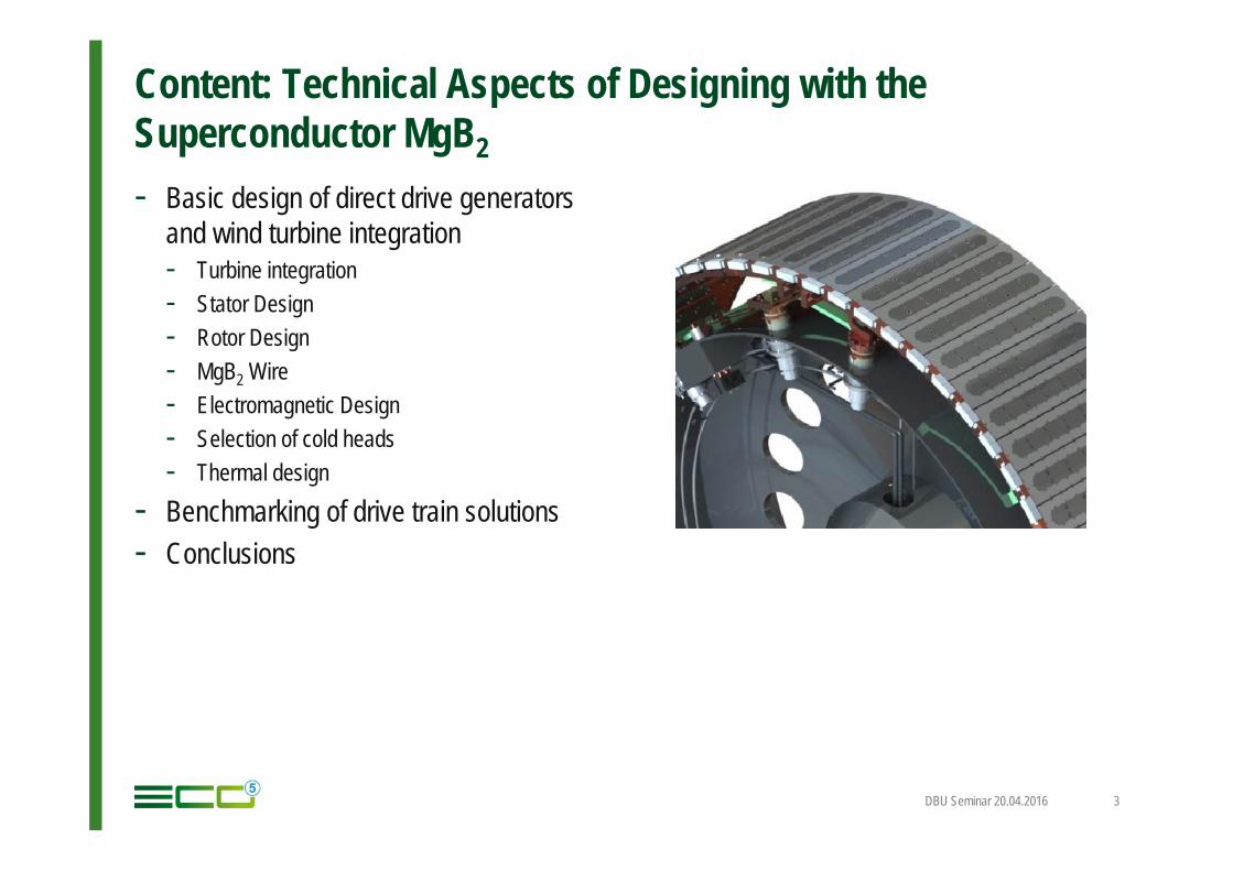
- Basic design of direct drive generatorsand wind turbine integration- Turbine integration- Stator Design- Rotor Design- MgB2 Wire- Electromagnetic Design- Selection of cold heads- Thermal design
- Benchmarking of drive train solutions- Conclusions
DBU Seminar 20.04.2016 3

Windspeed Target Parameters
DBU Seminar 20.04.2016 4
Property Value Comment
Axis of turbine horizontal Standard Turbine speed variable StandardRated speed 13 rpmRotor diameter 120 m example Rated tip speed of blades 81.68 m/s Limited by acoustic emissionsRated power of the turbine 3.6 MW at grid side of the converterPower converter type Full power converter StandardEfficiency of converter 97.5% (at rated)Losses in converter at rated load 92.31 kWGenerator type Direct drive, inner runner gearlessRated generator voltage 690 VNumber of phases 3 / 6 Standard is 3 Phases; 6 Phases
optionally for reduction of torque rippleNumber of stator systems 2…3 Limitation of short circuit torqueRated power out generator 3.69 MW (=input power for converter)Efficiency generator 94.2% Design targetGenerator losses at rated operation 227 kW Design targetRated air gap power of generator 3.92 MWRated torque of generator 2,88 MNmGenerator placement in turbine • „downwind“, or
• „upwind“Both is possible
Bearings None in the generator Only rotor lock for transportOuter generator diameter < 5500 mm For transport logist ics and market
acceptanceStator segmentation nonePol pair number generator Ca. 32Stator cooling a) A: radial air cooling
b) B: Axial through air cooling c) C: combined air/water cooling
Different cooling concepts have been investigated
Rotor cooling With GM coolers
Heat transfer in the cold rotor Heat conduction
Operating temperature rotor coils <= 20 K
Excitation of Synchronous Wind Generators
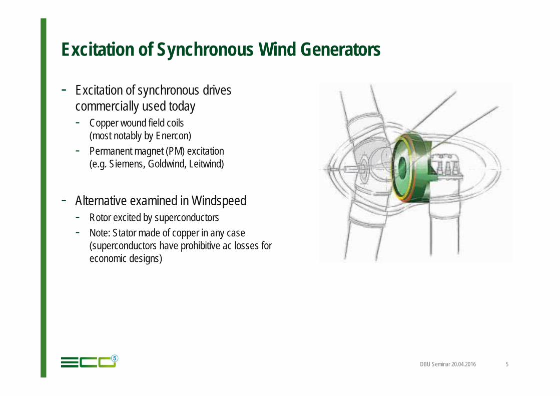
- Excitation of synchronous drivescommercially used today- Copper wound field coils
(most notably by Enercon)- Permanent magnet (PM) excitation
(e.g. Siemens, Goldwind, Leitwind)
- Alternative examined in Windspeed- Rotor excited by superconductors- Note: Stator made of copper in any case
(superconductors have prohibitive ac losses foreconomic designs)
DBU Seminar 20.04.2016 5
Basic Design of DD Wind Generators
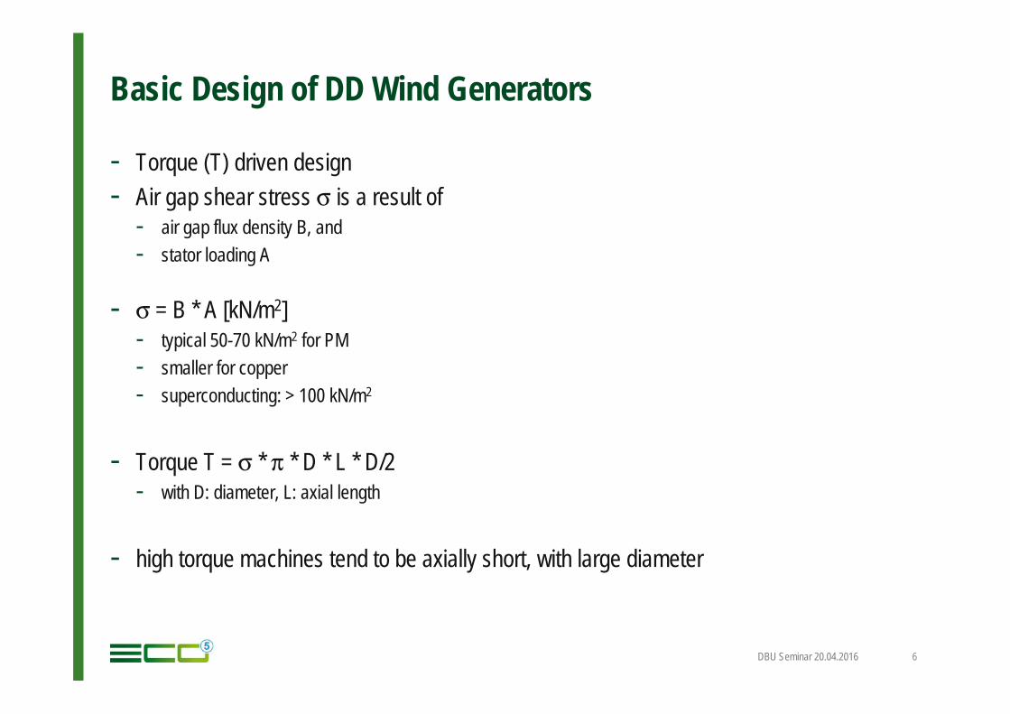
- Torque (T) driven design- Air gap shear stress σ is a result of
- air gap flux density B, and- stator loading A
- σ = B * A [kN/m2]- typical 50-70 kN/m2 for PM- smaller for copper- superconducting: > 100 kN/m2
- Torque T = σ * π * D * L * D/2- with D: diameter, L: axial length
- high torque machines tend to be axially short, with large diameter
DBU Seminar 20.04.2016 6
Basic Design of DD Wind Generators
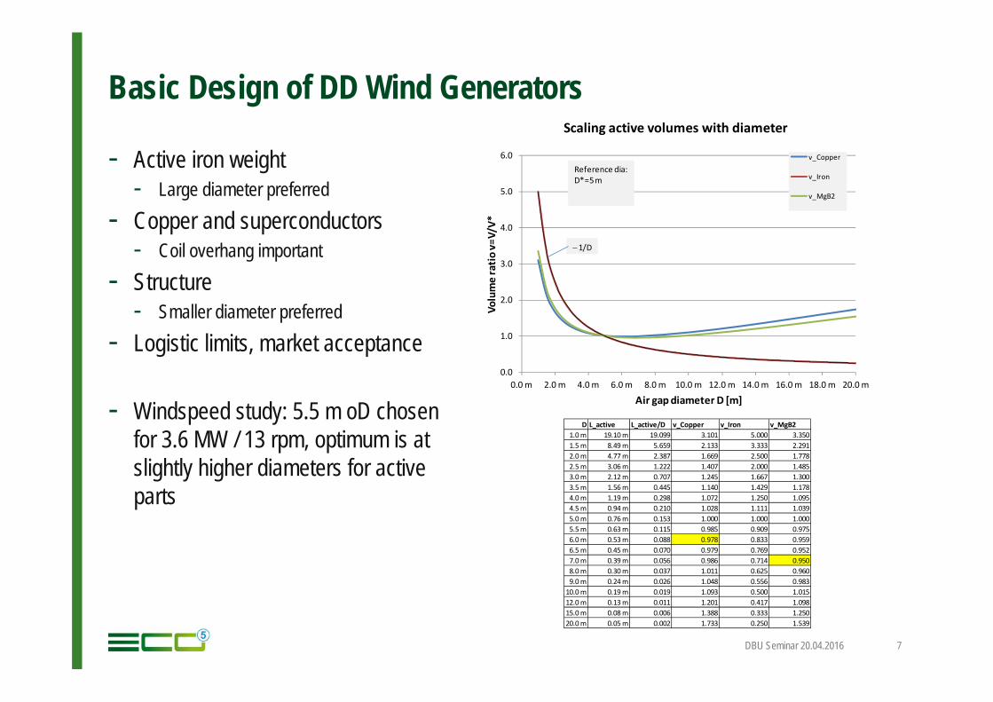
- Active iron weight- Large diameter preferred
- Copper and superconductors- Coil overhang important
- Structure- Smaller diameter preferred
- Logistic limits, market acceptance
- Windspeed study: 5.5 m oD chosenfor 3.6 MW / 13 rpm, optimum is atslightly higher diameters for activeparts
DBU Seminar 20.04.2016 7
0.0
1.0
2.0
3.0
4.0
5.0
6.0
0.0 m 2.0 m 4.0 m 6.0 m 8.0 m 10.0 m 12.0 m 14.0 m 16.0 m 18.0 m 20.0 m
Volu
me
ratio
v=V/
V*
Air gap diameter D [m]
Scaling active volumes with diameter
v_Copper
v_Iron
v_MgB2
Reference dia:D*=5 m
∼1/D
D L_active L_active/D v_Copper v_Iron v_MgB21.0 m 19.10 m 19.099 3.101 5.000 3.3501.5 m 8.49 m 5.659 2.133 3.333 2.2912.0 m 4.77 m 2.387 1.669 2.500 1.7782.5 m 3.06 m 1.222 1.407 2.000 1.4853.0 m 2.12 m 0.707 1.245 1.667 1.3003.5 m 1.56 m 0.445 1.140 1.429 1.1784.0 m 1.19 m 0.298 1.072 1.250 1.0954.5 m 0.94 m 0.210 1.028 1.111 1.0395.0 m 0.76 m 0.153 1.000 1.000 1.0005.5 m 0.63 m 0.115 0.985 0.909 0.9756.0 m 0.53 m 0.088 0.978 0.833 0.9596.5 m 0.45 m 0.070 0.979 0.769 0.9527.0 m 0.39 m 0.056 0.986 0.714 0.9508.0 m 0.30 m 0.037 1.011 0.625 0.9609.0 m 0.24 m 0.026 1.048 0.556 0.983
10.0 m 0.19 m 0.019 1.093 0.500 1.01512.0 m 0.13 m 0.011 1.201 0.417 1.09815.0 m 0.08 m 0.006 1.388 0.333 1.25020.0 m 0.05 m 0.002 1.733 0.250 1.539
Basic Design of DD Wind Generators
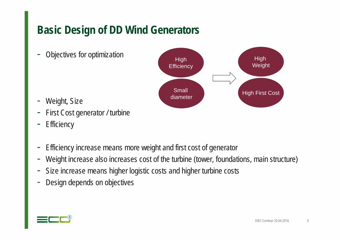
- Objectives for optimization
- Weight, Size- First Cost generator / turbine- Efficiency
- Efficiency increase means more weight and first cost of generator- Weight increase also increases cost of the turbine (tower, foundations, main structure)- Size increase means higher logistic costs and higher turbine costs- Design depends on objectives
DBU Seminar 20.04.2016 8
HighEfficiency
High First Cost
High Weight
Smalldiameter
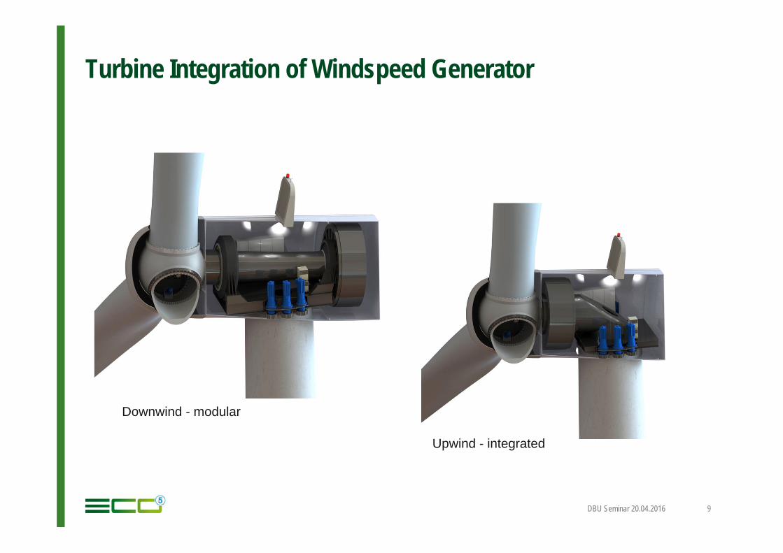
Turbine Integration of Windspeed Generator
DBU Seminar 20.04.2016 9
Downwind - modular
Upwind - integrated
Stator Design
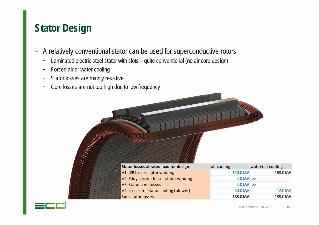
- A relatively conventional stator can be used for superconductive rotors- Laminated electric steel stator with slots – quite conventional (no air core design)- Forced air or water cooling- Stator losses are mainly resistive- Core losses are not too high due to low frequency
DBU Seminar 20.04.2016 10
Stator losses at rated load for design air cooling water+air coolingV1: I2R losses stator winding 150.0 kW 168.0 kWV2: Eddy current losses stator winding 4.0 kW ->>V3: Stator core losses 4.0 kW ->>V4: Losses for stator cooling (blower) 30.0 kW 12.0 kWSum stator losses 188.0 kW 188.0 kW
Rotor Design – Basic Options
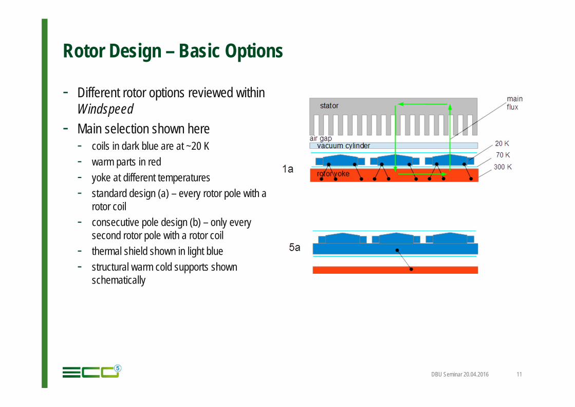
- Different rotor options reviewed withinWindspeed
- Main selection shown here- coils in dark blue are at ~20 K- warm parts in red- yoke at different temperatures- standard design (a) – every rotor pole with a
rotor coil- consecutive pole design (b) – only every
second rotor pole with a rotor coil- thermal shield shown in light blue- structural warm cold supports shown
schematically
DBU Seminar 20.04.2016 11
Basic Design Windspeed - Rotor
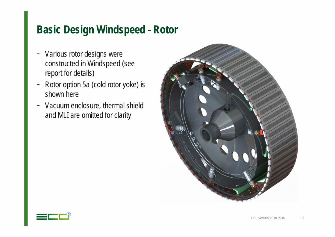
- Various rotor designs wereconstructed in Windspeed (seereport for details)
- Rotor option 5a (cold rotor yoke) isshown here
- Vacuum enclosure, thermal shieldand MLI are omitted for clarity
DBU Seminar 20.04.2016 12
Basic Design Windspeed - Rotor
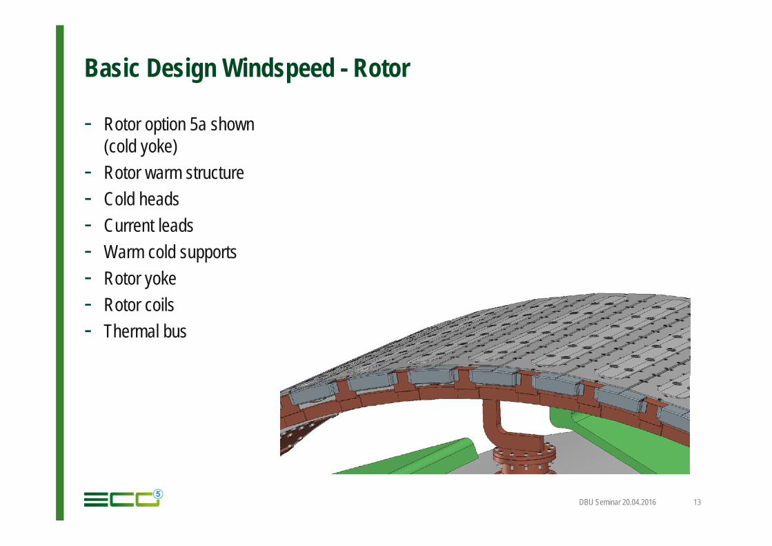
- Rotor option 5a shown(cold yoke)
- Rotor warm structure- Cold heads- Current leads- Warm cold supports- Rotor yoke- Rotor coils- Thermal bus
DBU Seminar 20.04.2016 13
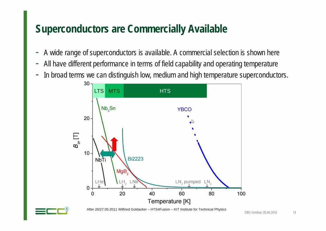
Superconductors are Commercially Available
- A wide range of superconductors is available. A commercial selection is shown here- All have different performance in terms of field capability and operating temperature- In broad terms we can distinguish low, medium and high temperature superconductors.
DBU Seminar 20.04.2016 14After 26/27.05.2011 Wilfried Goldacker – HTS4Fusion – KIT Institute for Technical Physics
LTS MTS HTS
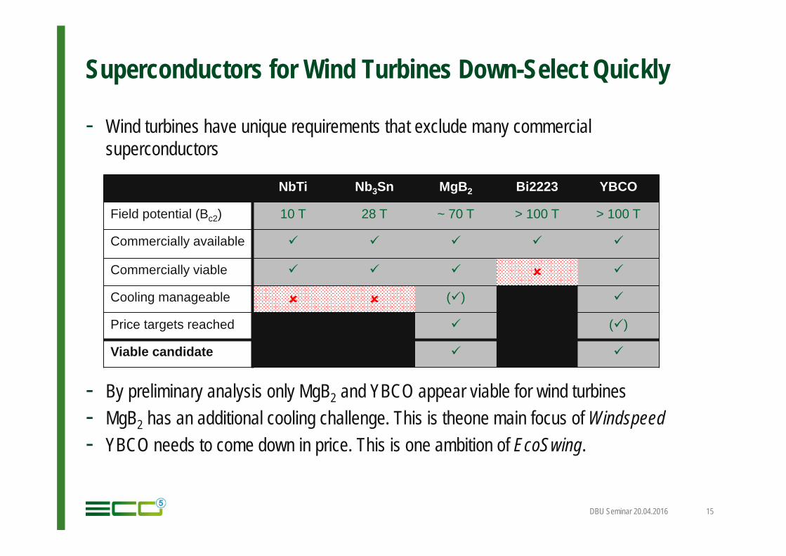
Superconductors for Wind Turbines Down-Select Quickly
- Wind turbines have unique requirements that exclude many commercial superconductors
- By preliminary analysis only MgB2 and YBCO appear viable for wind turbines- MgB2 has an additional cooling challenge. This is theone main focus of Windspeed- YBCO needs to come down in price. This is one ambition of EcoSwing.
DBU Seminar 20.04.2016 15
NbTi Nb3Sn MgB2 Bi2223 YBCO
Field potential (Bc2) 10 T 28 T ~ 70 T > 100 T > 100 T
Commercially available
Commercially viable
Cooling manageable ()
Price targets reached ()
Viable candidate
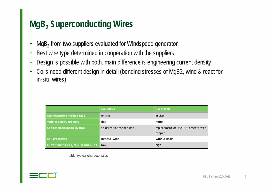
MgB2 Superconducting Wires
- MgB2 from two suppliers evaluated for Windspeed generator- Best wire type determined in cooperation with the suppliers- Design is possible with both, main difference is engineering current density- Coils need different design in detail (bending stresses of MgB2, wind & react for
in-situ wires)
DBU Seminar 20.04.2016 16
Columbus HyperTech
Manufacturing method MgB2 ex-situ in-situ
Wire geometry for coils flat round
Copper stabilization (typical) soldered flat copper strip replacement of MgB2 filaments with
copper
Coil processing React & Wind Wind & React
Current densities Je at 20 K and 1…2 T low high
table: typical characteristics
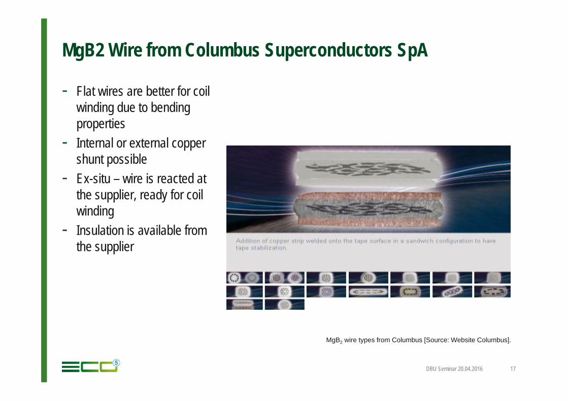
MgB2 Wire from Columbus Superconductors SpA
- Flat wires are better for coil winding due to bending properties
- Internal or external copper shunt possible
- Ex-situ – wire is reacted at the supplier, ready for coil winding
- Insulation is available from the supplier
DBU Seminar 20.04.2016 17
MgB2 wire types from Columbus [Source: Website Columbus].
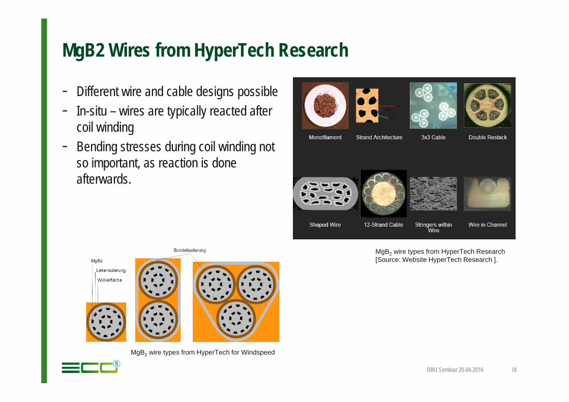
MgB2 Wires from HyperTech Research
- Different wire and cable designs possible- In-situ – wires are typically reacted after
coil winding- Bending stresses during coil winding not
so important, as reaction is doneafterwards.
DBU Seminar 20.04.2016 18
MgB2 wire types from HyperTech Research [Source: Website HyperTech Research ].
MgB2 wire types from HyperTech for Windspeed
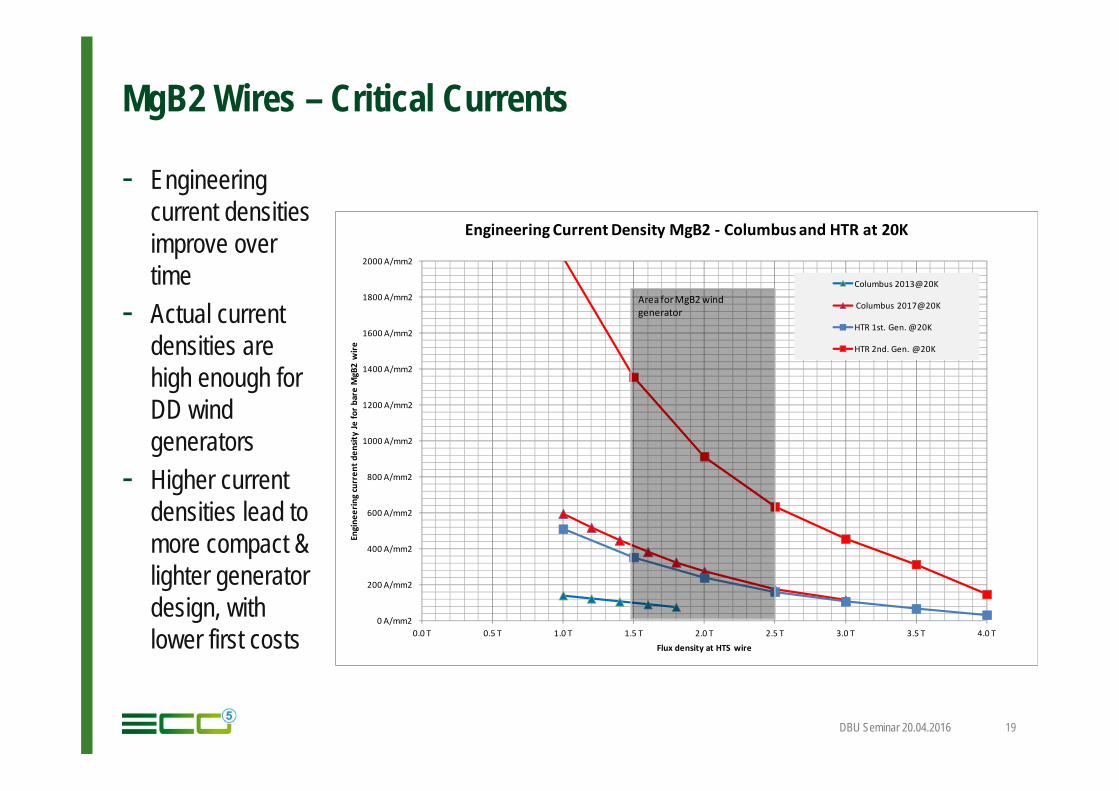
MgB2 Wires – Critical Currents
- Engineering current densitiesimprove overtime
- Actual currentdensities arehigh enough forDD wind generators
- Higher currentdensities lead tomore compact & lighter generatordesign, withlower first costs
DBU Seminar 20.04.2016 19
0 A/mm2
200 A/mm2
400 A/mm2
600 A/mm2
800 A/mm2
1000 A/mm2
1200 A/mm2
1400 A/mm2
1600 A/mm2
1800 A/mm2
2000 A/mm2
0.0 T 0.5 T 1.0 T 1.5 T 2.0 T 2.5 T 3.0 T 3.5 T 4.0 T
Engi
neer
ing
curr
ent d
ensit
y Je
for b
are
MgB
2 w
ire
Flux density at HTS wire
Engineering Current Density MgB2 - Columbus and HTR at 20K
Columbus 2013@20K
Columbus 2017@20K
HTR 1st. Gen. @20K
HTR 2nd. Gen. @20K
Area for MgB2 wind generator
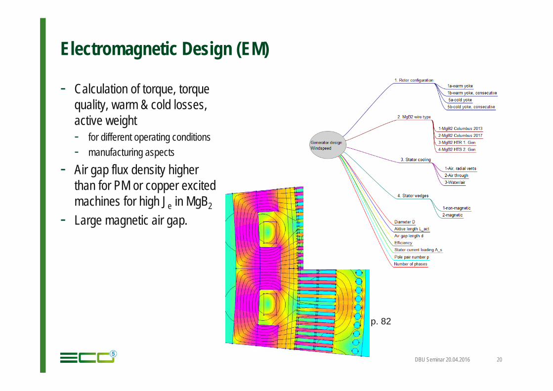
Electromagnetic Design (EM)
- Calculation of torque, torquequality, warm & cold losses, active weight- for different operating conditions- manufacturing aspects
- Air gap flux density higherthan for PM or copper excitedmachines for high Je in MgB2
- Large magnetic air gap.
DBU Seminar 20.04.2016 20
p. 82
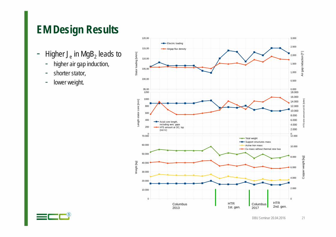
EM Design Results
DBU Seminar 20.04.2016 21
- Higher Je in MgB2 leads to- higher air gap induction,- shorter stator, - lower weight.
95,00
100,00
105,00
110,00
115,00
120,00
0,000
0,500
1,000
1,500
2,000
2,500
3,000
Electric loading
Airgap flux density
Sta
tor l
oadi
ng [k
A/m
]
Air
gap
indu
ctio
n [T
]
0
200
400
600
800
1000
1200
0
2.000
4.000
6.000
8.000
10.000
12.000
14.000
16.000
18.000
Axial core length, including vent. gapsHTS amount at OC, Iop (not Ic)
Leng
th s
tato
r cor
e [m
m]
HTS
wire
am
ount
at O
C [k
Am]
0
10.000
20.000
30.000
40.000
50.000
60.000
70.000
0
2.000
4.000
6.000
8.000
10.000
12.000Total weightSupport structures massActive Iron massCu mass without thermal rotor bus
Wei
ght [
kg]
Cop
per w
eigh
t [kg
]
Columbus2017
HTR1st. gen.
Columbus2013
HTR2nd. gen.
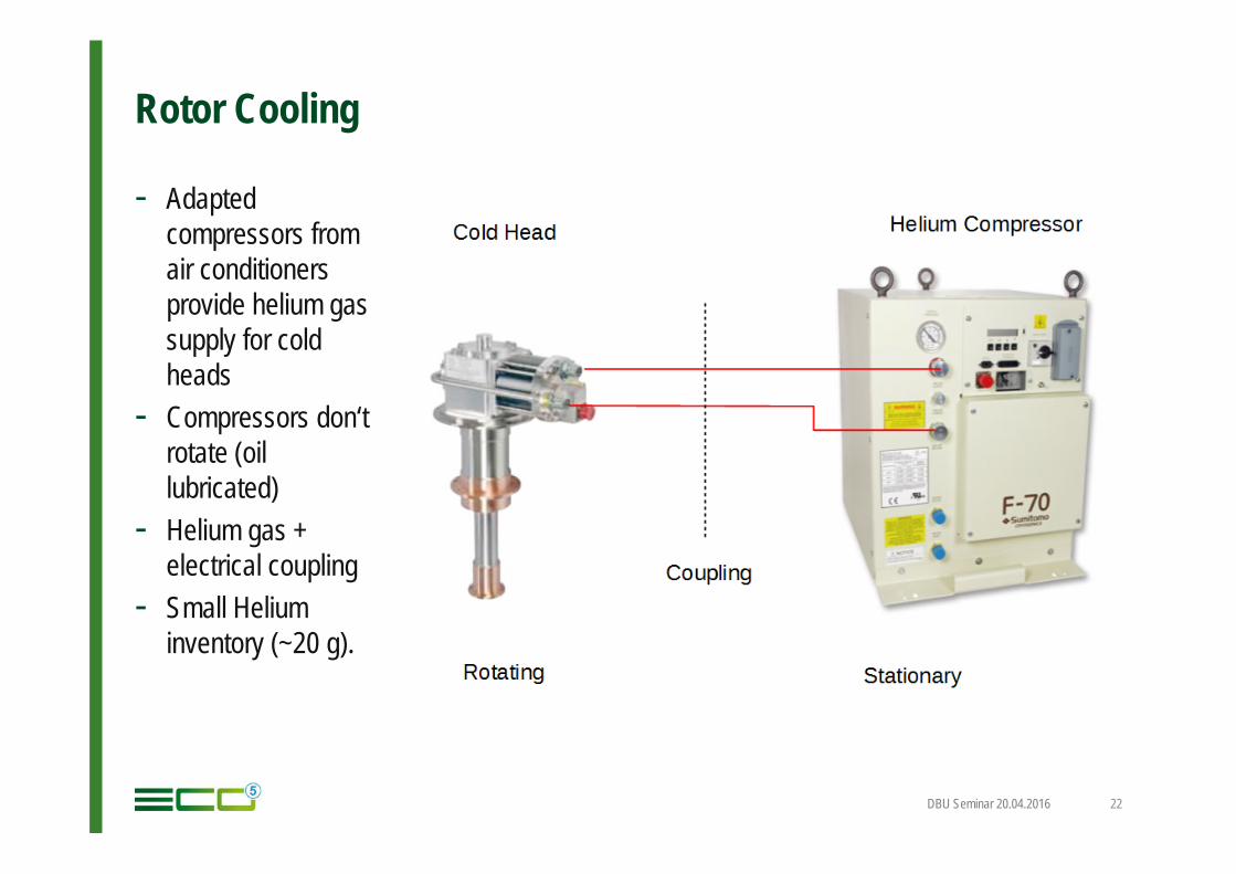
Rotor Cooling
- Adaptedcompressors fromair conditionersprovide helium gas supply for coldheads
- Compressors don‘trotate (oillubricated)
- Helium gas + electrical coupling
- Small Helium inventory (~20 g).
DBU Seminar 20.04.2016 22
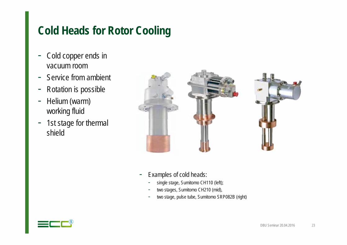
Cold Heads for Rotor Cooling
- Examples of cold heads: - single stage, Sumitomo CH110 (left); - two stages, Sumitomo CH210 (mid), - two stage, pulse tube, Sumitomo SRP082B (right)
DBU Seminar 20.04.2016 23
- Cold copper ends invacuum room
- Service from ambient- Rotation is possible- Helium (warm)
working fluid- 1st stage for thermal
shield
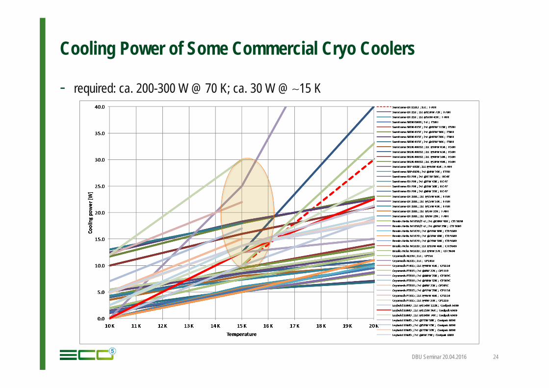
Cooling Power of Some Commercial Cryo Coolers
- required: ca. 200-300 W @ 70 K; ca. 30 W @ ∼15 K
DBU Seminar 20.04.2016 24
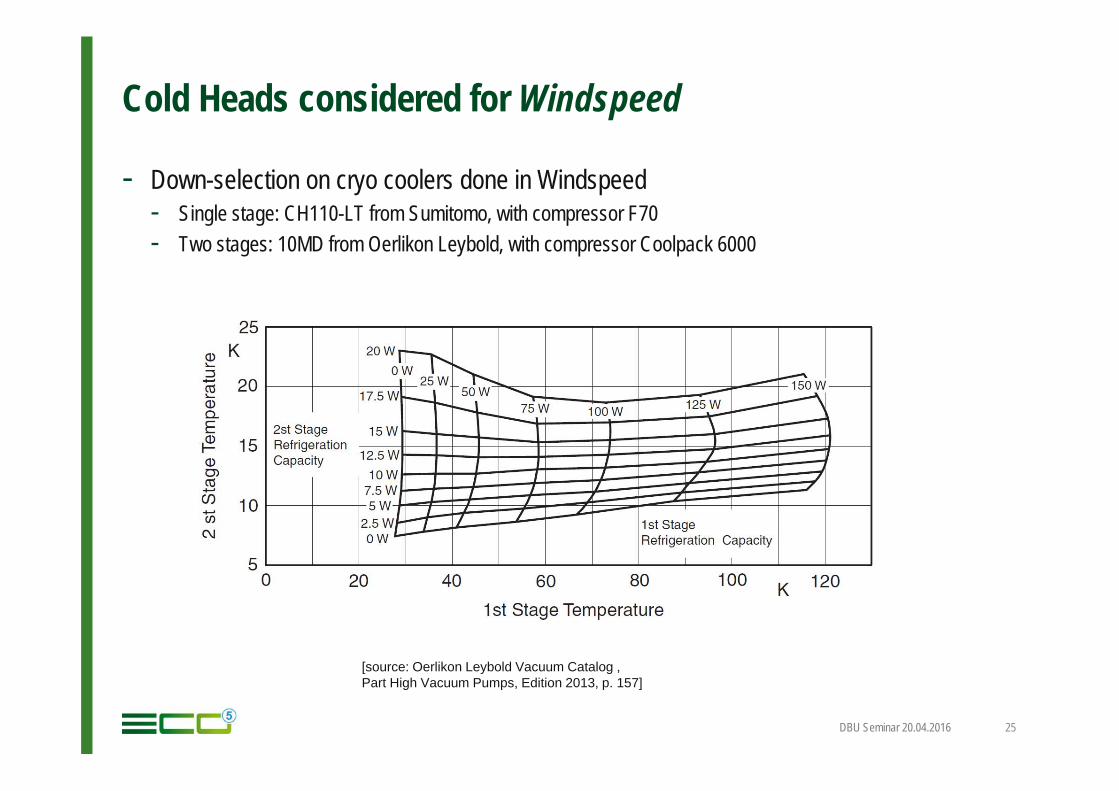
Cold Heads considered for Windspeed
- Down-selection on cryo coolers done in Windspeed- Single stage: CH110-LT from Sumitomo, with compressor F70- Two stages: 10MD from Oerlikon Leybold, with compressor Coolpack 6000
DBU Seminar 20.04.2016 25
[source: Oerlikon Leybold Vacuum Catalog ,Part High Vacuum Pumps, Edition 2013, p. 157]
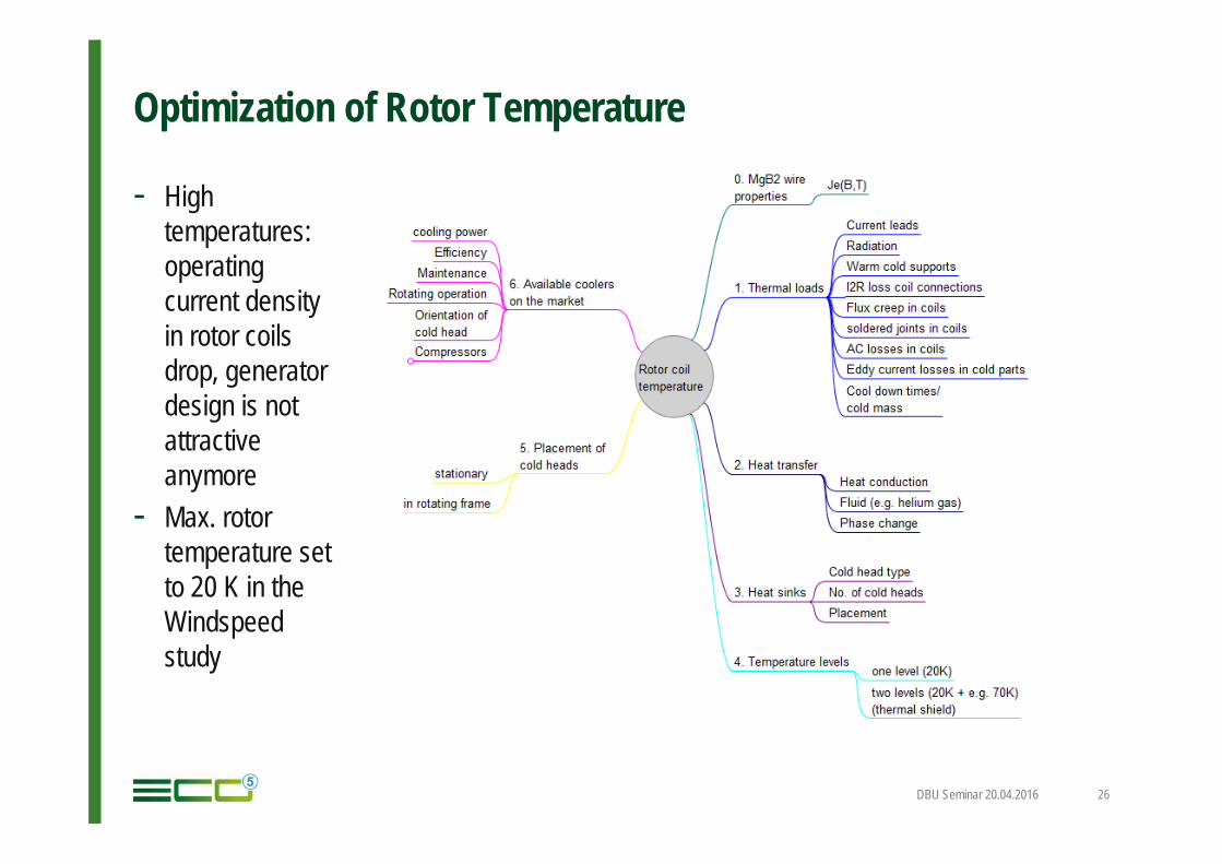
Optimization of Rotor Temperature
- High temperatures: operatingcurrent densityin rotor coilsdrop, generatordesign is not attractiveanymore
- Max. rotortemperature setto 20 K in theWindspeed study
DBU Seminar 20.04.2016 26
Thermal Rotor Design - Loads
- Number of temperature levels – 1 or 2 (2 = with thermal shield)
- Heat loads- Radiation – ca. 2 W/m2 to first cold surface, much less to second cold surface if surrounded by a thermal
shield- Heat conduction (warm cold supports) – 10 W...100 W- Cold losses (eddy current losses, flux creep in MgB2, joule heating in joints) - small- Current leads (combination of heat conduction and joule heating) – ca. 45 W/kA- In total, about (200…300) W in the rotor, when two temperature levels are used, about 10% of the full
losses at the second stage.
DBU Seminar 20.04.2016 27
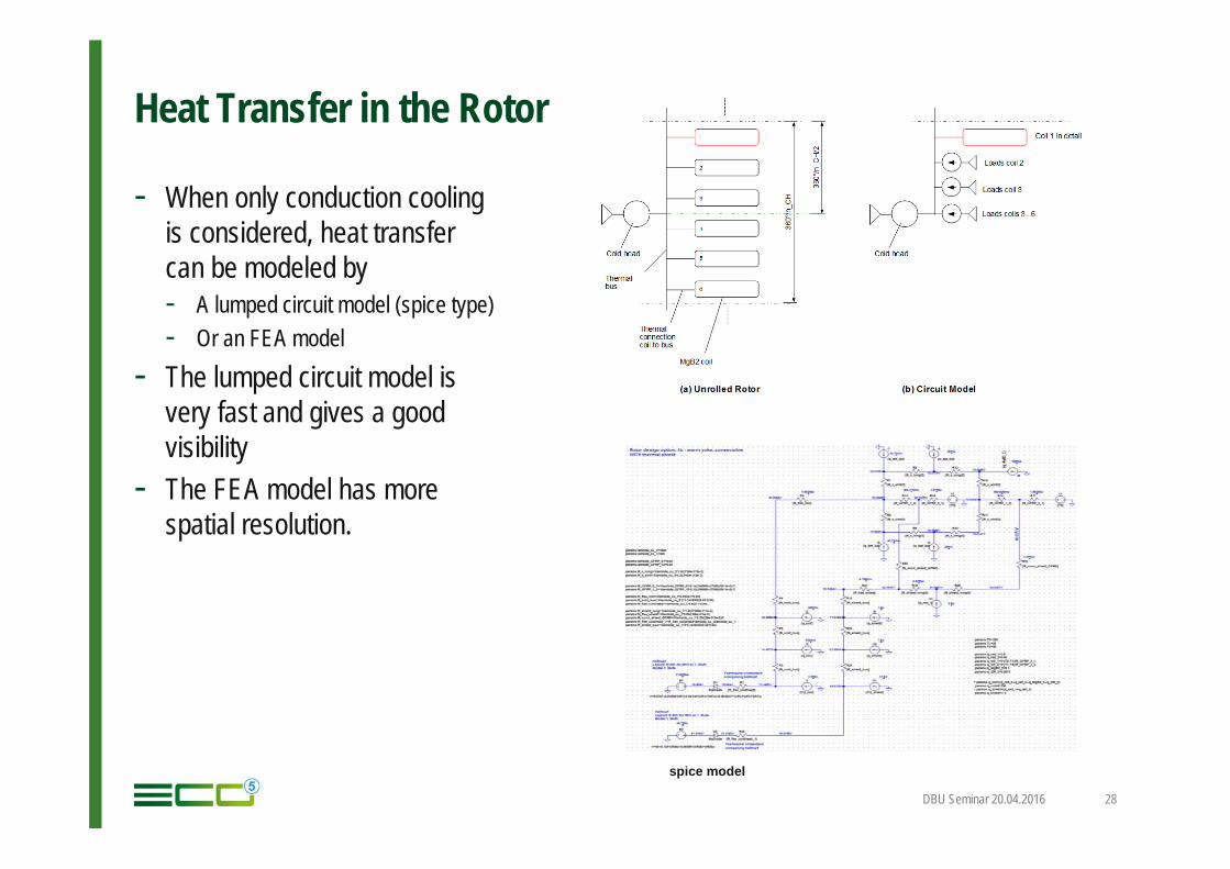
Heat Transfer in the Rotor
- When only conduction coolingis considered, heat transfercan be modeled by- A lumped circuit model (spice type)- Or an FEA model
- The lumped circuit model isvery fast and gives a goodvisibility
- The FEA model has morespatial resolution.
DBU Seminar 20.04.2016 28
spice model
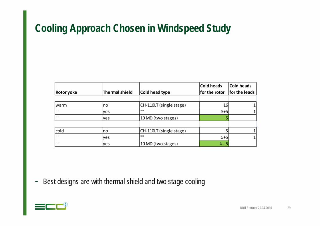
Cooling Approach Chosen in Windspeed Study
- Best designs are with thermal shield and two stage cooling
DBU Seminar 20.04.2016 29
Rotor yoke Thermal shield Cold head typeCold heads for the rotor
Cold heads for the leads
warm no CH-110LT (single stage) 16 1"" yes "" 5+5 1"" yes 10 MD (two stages) 5
cold no CH-110LT (single stage) 5 1"" yes "" 5+5 1"" yes 10 MD (two stages) 4...5
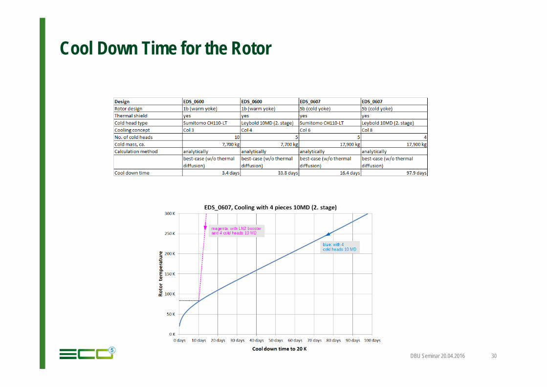
Cool Down Time for the Rotor
DBU Seminar 20.04.2016 30
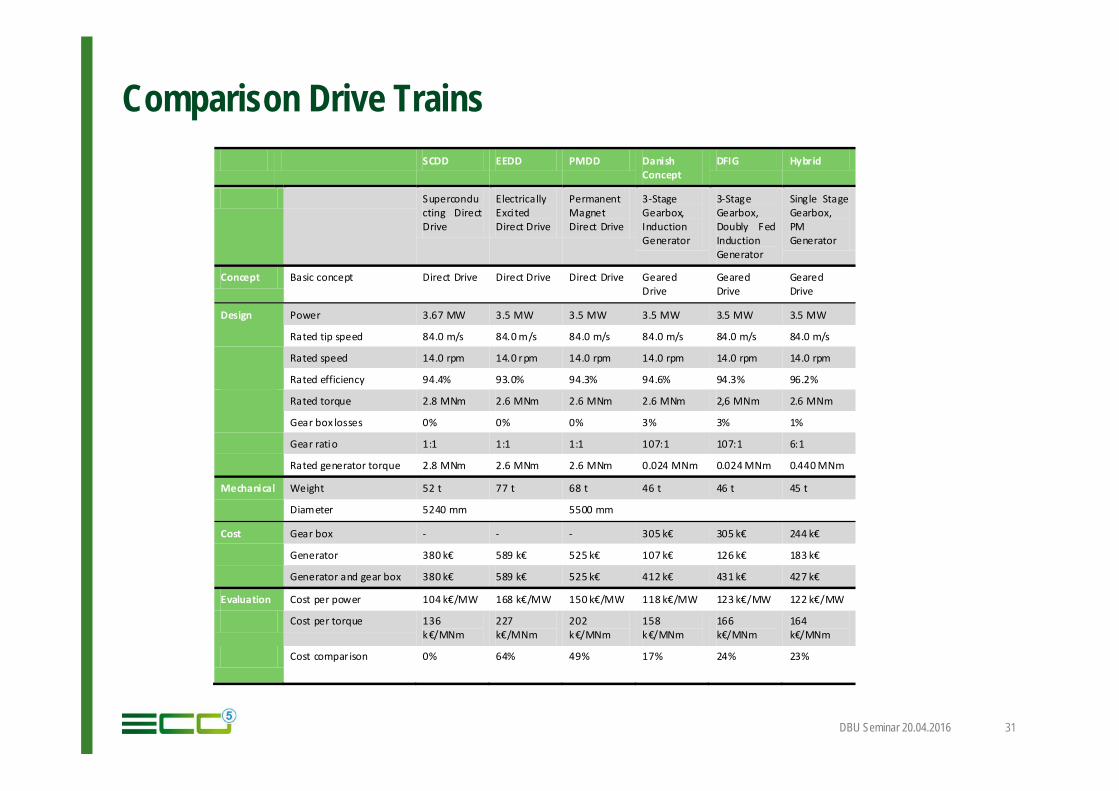
Comparison Drive Trains
DBU Seminar 20.04.2016 31
SCDD EEDD PMDD Danish Concept
DFIG Hybrid
Superconducting Direct Drive
Electrically Exci ted Direct Drive
Permanent Magnet Direct Drive
3-Stage Gearbox, Induction Generator
3-Stage Gearbox, Doubly Fed Induction Generator
Single Stage Gearbox, PM Generator
Concept Basic concept Direct Drive Direct Drive Direct Drive Geared Drive
Geared Drive
Geared Drive
Design Power 3.67 MW 3.5 MW 3.5 MW 3.5 MW 3.5 MW 3.5 MW
Rated tip speed 84.0 m/s 84.0 m/s 84.0 m/s 84.0 m/s 84.0 m/s 84.0 m/s
Rated speed 14.0 rpm 14.0 rpm 14.0 rpm 14.0 rpm 14.0 rpm 14.0 rpm
Rated efficiency 94.4% 93.0% 94.3% 94.6% 94.3% 96.2%
Rated torque 2.8 MNm 2.6 MNm 2.6 MNm 2.6 MNm 2,6 MNm 2.6 MNm
Gear box losses 0% 0% 0% 3% 3% 1%
Gear ratio 1:1 1:1 1:1 107:1 107:1 6:1
Rated generator torque 2.8 MNm 2.6 MNm 2.6 MNm 0.024 MNm 0.024 MNm 0.440 MNm
Mechanical Weight 52 t 77 t 68 t 46 t 46 t 45 t
Diameter 5240 mm 5500 mm
Cost Gear box - - - 305 k€ 305 k€ 244 k€
Generator 380 k€ 589 k€ 525 k€ 107 k€ 126 k€ 183 k€
Generator and gear box 380 k€ 589 k€ 525 k€ 412 k€ 431 k€ 427 k€
Evaluation Cost per power 104 k€/MW 168 k€/MW 150 k€/MW 118 k€/MW 123 k€/MW 122 k€/MW
Cost per torque 136 k€/MNm
227 k€/MNm
202 k€/MNm
158 k€/MNm
166 k€/MNm
164 k€/MNm
Cost comparison 0% 64% 49% 17% 24% 23%
Conclusions of Windspeed
- Critical current of commercial MgB2 wires are sufficient for designing wind turbine generators with high gap shear stresses
- Main challenge is the thermal design of the rotor- Rotor operating temperatures of about 20 K can be reached with state-of-the-art cryocoolers- Thermal shield for the rotor is recommended- Two-stage cold heads preferred for cooling with thermal conduction- Booster for pre-cooling of the rotor is recommended
DBU Seminar 20.04.2016 32
ECO 5: Engineering for High-Efficient Businesses
33DBU Seminar 20.04.2016


![Calibration Center.pptx [Salt Okunur] · CalibrationCenterofTurkishStateMeteorologicalService(TSMS)was modernizedin2009andbegantoserveforthecalibrationsofTemperature, RelativeHumidity,Pressure,WindSpeed](https://img.pdfslide.us/doc/110x75/6017a9d5815da76ba748c21f/calibration-salt-okunur-calibrationcenterofturkishstatemeteorologicalservicetsmswas.jpg)