Embed Size (px)
Citation preview

WinDriver™ USB User'sManual
Version 11.1.0
Jungo Ltd.
© Jungo Ltd. 2005–2012
WinDriver™ USB User's Manual: Version 11.1.0Copyright © Jungo Ltd. 2005–2012 All Rights Reserved.
Information in this document is subject to change without notice. The software described in this document is furnished under a licenseagreement. The software may be used, copied or distributed only in accordance with that agreement. No part of this publicationmay be reproduced, stored in a retrieval system, or transmitted in any form or any means, electronically or mechanically, includingphotocopying and recording for any purpose without the written permission of Jungo Ltd.
Brand and product names mentioned in this document are trademarks of their respective owners and are used here only foridentification purposes.

© Jungo Ltd. 2005–2012 iii
Table of Contents1. WinDriver Overview .................................................................................................................. 1
1.1. Introduction to WinDriver .............................................................................................. 11.2. Background ..................................................................................................................... 2
1.2.1. The Challenge ...................................................................................................... 21.2.2. The WinDriver Solution ...................................................................................... 2
1.3. Conclusion ....................................................................................................................... 31.4. WinDriver Benefits ......................................................................................................... 31.5. WinDriver Architecture .................................................................................................. 41.6. What Platforms Does WinDriver Support? .................................................................... 51.7. Limitations of the Different Evaluation Versions ........................................................... 51.8. How Do I Develop My Driver with WinDriver? ........................................................... 6
1.8.1. On Windows and Linux ....................................................................................... 61.8.2. On Windows CE .................................................................................................. 6
1.9. What Does the WinDriver Toolkit Include? ................................................................... 61.9.1. WinDriver Modules ............................................................................................. 71.9.2. Utilities ................................................................................................................. 81.9.3. WinDriver's Specific Chipset Support ................................................................. 81.9.4. Samples ................................................................................................................ 8
1.10. Can I Distribute the Driver Created with WinDriver? .................................................. 92. Understanding Device Drivers ................................................................................................. 10
2.1. Device Driver Overview ............................................................................................... 102.2. Classification of Drivers According to Functionality ................................................... 10
2.2.1. Monolithic Drivers ............................................................................................. 102.2.2. Layered Drivers .................................................................................................. 112.2.3. Miniport Drivers ................................................................................................ 12
2.3. Classification of Drivers According to Operating Systems .......................................... 132.3.1. WDM Drivers .................................................................................................... 132.3.2. VxD Drivers ....................................................................................................... 142.3.3. Unix Device Drivers .......................................................................................... 142.3.4. Linux Device Drivers ......................................................................................... 14
2.4. The Entry Point of the Driver ...................................................................................... 152.5. Associating the Hardware with the Driver ................................................................... 152.6. Communicating with Drivers ........................................................................................ 15
3. WinDriver USB Overview ....................................................................................................... 163.1. Introduction to USB ...................................................................................................... 163.2. WinDriver USB Benefits .............................................................................................. 173.3. USB Components .......................................................................................................... 173.4. Data Flow in USB Devices .......................................................................................... 183.5. USB Data Exchange ..................................................................................................... 193.6. USB Data Transfer Types ............................................................................................. 20
3.6.1. Control Transfer ................................................................................................. 213.6.2. Isochronous Transfer .......................................................................................... 213.6.3. Interrupt Transfer ............................................................................................... 213.6.4. Bulk Transfer ..................................................................................................... 22
3.7. USB Configuration ....................................................................................................... 223.8. WinDriver USB ............................................................................................................ 24
© Jungo Ltd. 2005–2012 iv
3.9. WinDriver USB Architecture ....................................................................................... 254. Installing WinDriver ................................................................................................................ 27
4.1. System Requirements .................................................................................................... 274.1.1. Windows System Requirements ........................................................................ 274.1.2. Windows CE System Requirements .................................................................. 274.1.3. Linux System Requirements .............................................................................. 28
4.2. WinDriver Installation Process ..................................................................................... 284.2.1. Windows WinDriver Installation Instructions ................................................... 284.2.2. Windows CE WinDriver Installation Instructions ............................................. 29
4.2.2.1. Installing WinDriver CE when Building New CE-Based Platforms ........ 294.2.2.2. Installing WinDriver CE when Developing Applications for WindowsCE Computers ...................................................................................................... 314.2.2.3. Windows CE Installation Note ............................................................... 32
4.2.3. Linux WinDriver Installation Instructions ......................................................... 324.2.3.1. Preparing the System for Installation ...................................................... 324.2.3.2. Installation ............................................................................................... 34
4.2.3.2.1. Installation using a Debian or RPM Installation Package ............. 344.2.3.2.2. Manual Installation ....................................................................... 344.2.3.2.3. Registering Your WinDriver License ........................................... 36
4.2.3.3. Restricting Hardware Access on Linux ................................................... 374.3. Upgrading Your Installation ......................................................................................... 374.4. Checking Your Installation ........................................................................................... 37
4.4.1. Windows and Linux Installation Check ............................................................. 374.4.2. Windows CE Installation Check ........................................................................ 38
4.5. Uninstalling WinDriver ................................................................................................. 384.5.1. Windows WinDriver Uninstall Instructions ....................................................... 384.5.2. Linux WinDriver Uninstall Instructions ............................................................ 40
5. Using DriverWizard ................................................................................................................. 415.1. An Overview ................................................................................................................. 415.2. DriverWizard Walkthrough ........................................................................................... 42
5.2.1. Automatic Code Generation ............................................................................... 515.2.1.1. Generating the Code ............................................................................... 515.2.1.2. The Generated USB C Code ................................................................... 515.2.1.3. The Generated Visual Basic and Delphi Code ........................................ 515.2.1.4. The Generated C# and Visual Basic .NET Code .................................... 52
5.2.2. Compiling the Generated Code .......................................................................... 525.2.2.1. Windows and Windows CE Compilation ............................................... 525.2.2.2. Linux Compilation .................................................................................. 52
5.2.3. Bus Analyzer Integration — Ellisys Visual USB .............................................. 526. Developing a Driver ................................................................................................................ 54
6.1. Using DriverWizard to Build a Device Driver ............................................................. 546.2. Writing the Device Driver Without DriverWizard ....................................................... 55
6.2.1. Include the Required WinDriver Files ............................................................... 556.2.2. Write Your Code ................................................................................................ 566.2.3. Configure and Build Your Code ........................................................................ 56
6.3. Developing Your Driver on Windows CE Platforms ................................................... 576.4. Developing in Visual Basic and Delphi ........................................................................ 58
6.4.1. Using DriverWizard ........................................................................................... 58
© Jungo Ltd. 2005–2012 v
6.4.2. Samples .............................................................................................................. 586.4.3. Creating your Driver .......................................................................................... 58
7. Debugging Drivers ................................................................................................................... 597.1. User-Mode Debugging .................................................................................................. 597.2. Debug Monitor .............................................................................................................. 59
7.2.1. The wddebug_gui Utility .................................................................................. 607.2.1.1. Running wddebug_gui for a Renamed Driver ....................................... 62
7.2.2. The wddebug Utility ......................................................................................... 627.2.2.1. Console-Mode wddebug Execution ........................................................ 627.2.2.2. Windows CE GUI wddebug Execution ................................................. 65
8. Enhanced Support for Specific Chipsets ................................................................................. 678.1. Overview ....................................................................................................................... 678.2. Developing a Driver Using the Enhanced Chipset Support .......................................... 67
9. USB Transfers .......................................................................................................................... 689.1. Overview ....................................................................................................................... 689.2. USB Control Transfers ................................................................................................. 69
9.2.1. USB Control Transfers Overview ...................................................................... 699.2.1.1. Control Data Exchange ........................................................................... 699.2.1.2. More About the Control Transfer ........................................................... 699.2.1.3. The Setup Packet .................................................................................... 709.2.1.4. USB Setup Packet Format ...................................................................... 709.2.1.5. Standard Device Request Codes ............................................................. 719.2.1.6. Setup Packet Example ............................................................................. 71
9.2.2. Performing Control Transfers with WinDriver .................................................. 729.2.2.1. Control Transfers with DriverWizard ..................................................... 729.2.2.2. Control Transfers with WinDriver API ................................................... 74
9.3. Functional USB Data Transfers .................................................................................... 759.3.1. Functional USB Data Transfers Overview ........................................................ 759.3.2. Single-Blocking Transfers .................................................................................. 75
9.3.2.1. Performing Single-Blocking Transfers with WinDriver .......................... 759.3.3. Streaming Data Transfers ................................................................................... 75
9.3.3.1. Performing Streaming with WinDriver ................................................... 7610. Dynamically Loading Your Driver ........................................................................................ 78
10.1. Why Do You Need a Dynamically Loadable Driver? ................................................ 7810.2. Windows Dynamic Driver Loading ............................................................................ 78
10.2.1. Windows Driver Types .................................................................................... 7810.2.2. The wdreg Utility ............................................................................................. 78
10.2.2.1. Overview ............................................................................................... 7910.2.3. Dynamically Loading/Unloading windrvr6.sys INF Files ............................... 80
10.3. Linux Dynamic Driver Loading ................................................................................. 8110.4. Windows CE Dynamic Driver Loading ...................................................................... 81
11. Distributing Your Driver ....................................................................................................... 8211.1. Getting a Valid License for WinDriver ...................................................................... 8211.2. Windows Driver Distribution ...................................................................................... 82
11.2.1. Preparing the Distribution Package .................................................................. 8311.2.2. Installing Your Driver on the Target Computer ............................................... 83
11.3. Windows CE Driver Distribution ............................................................................... 8611.3.1. Distribution to New Windows CE Platforms ................................................... 86
© Jungo Ltd. 2005–2012 vi
11.3.2. Distribution to Windows CE Computers ......................................................... 8811.4. Linux Driver Distribution ........................................................................................... 89
11.4.1. Preparing the Distribution Package .................................................................. 8911.4.1.1. Kernel Module Components ................................................................. 8911.4.1.2. User-Mode Hardware Control Application or Shared Object ................ 91
11.4.2. Building and Installing the WinDriver Driver Modules on the Target ............. 9211.4.3. Intsalling the User-Mode Hardware Control Application or Shared Object........................................................................................................................................ 93
12. Driver Installation — Advanced Issues ................................................................................. 9412.1. Windows INF Files ..................................................................................................... 94
12.1.1. Why Should I Create an INF File? .................................................................. 9412.1.2. How Do I Install an INF File When No Driver Exists? ................................... 9512.1.3. How Do I Replace an Existing Driver Using the INF File? ............................. 95
12.2. Renaming the WinDriver Kernel Driver .................................................................... 9612.2.1. Windows Driver Renaming ............................................................................. 9712.2.2. Linux Driver Renaming ................................................................................... 99
12.3. Windows Digital Driver Signing and Certification .................................................. 10012.3.1. Overview ........................................................................................................ 100
12.3.1.1. Authenticode Driver Signature ............................................................ 10112.3.1.2. WHQL Driver Certification ................................................................ 101
12.3.2. Driver Signing and Certification of WinDriver-Based Drivers ...................... 10212.3.2.1. WHQL DTM Test Notes .................................................................... 104
12.4. Windows XP Embedded WinDriver Component ..................................................... 104A. 64-Bit Operating Systems Support ....................................................................................... 106
A.1. Supported 64-Bit Architectures .................................................................................. 106A.2. Support for 32-Bit Applications on 64-Bit Windows and Linux Platforms ............... 106A.3. 64-Bit and 32-Bit Data Types .................................................................................... 107
B. WinDriver USB Host API Reference ................................................................................... 108B.1. WD_DriverName ........................................................................................................ 108B.2. WinDriver USB (WDU) Library Overview ............................................................... 109
B.2.1. Calling Sequence for WinDriver USB ............................................................ 109B.2.2. Upgrading from the WD_xxx USB API to the WDU_xxx API ...................... 112
B.3. USB User Callback Functions ................................................................................... 113B.3.1. WDU_ATTACH_CALLBACK ...................................................................... 113B.3.2. WDU_DETACH_CALLBACK ...................................................................... 114B.3.3. WDU_POWER_CHANGE_CALLBACK ...................................................... 115
B.4. USB Functions ........................................................................................................... 116B.4.1. WDU_Init ........................................................................................................ 116B.4.2. WDU_SetInterface ........................................................................................... 117B.4.3. WDU_GetDeviceAddr ..................................................................................... 118B.4.4. WDU_GetDeviceRegistryProperty .................................................................. 119B.4.5. WDU_GetDeviceInfo ...................................................................................... 120B.4.6. WDU_PutDeviceInfo ....................................................................................... 121B.4.7. WDU_Uninit .................................................................................................... 122B.4.8. Single-Blocking Transfer Functions ................................................................ 123
B.4.8.1. WDU_Transfer ..................................................................................... 123B.4.8.2. WDU_HaltTransfer ............................................................................... 125B.4.8.3. WDU_TransferDefaultPipe .................................................................. 126
© Jungo Ltd. 2005–2012 vii
B.4.8.4. WDU_TransferBulk .............................................................................. 126B.4.8.5. WDU_TransferIsoch ............................................................................. 127B.4.8.6. WDU_TransferInterrupt ........................................................................ 127
B.4.9. Streaming Data Transfer Functions ................................................................. 128B.4.9.1. WDU_StreamOpen ............................................................................... 128B.4.9.2. WDU_StreamStart ................................................................................ 130B.4.9.3. WDU_StreamRead ............................................................................... 131B.4.9.4. WDU_StreamWrite ............................................................................... 132B.4.9.5. WDU_StreamFlush ............................................................................... 133B.4.9.6. WDU_StreamGetStatus ........................................................................ 134B.4.9.7. WDU_StreamStop ................................................................................ 135B.4.9.8. WDU_StreamClose ............................................................................... 135
B.4.10. WDU_ResetPipe ............................................................................................ 136B.4.11. WDU_ResetDevice ........................................................................................ 137B.4.12. WDU_SelectiveSuspend ................................................................................ 138B.4.13. WDU_Wakeup ............................................................................................... 139B.4.14. WDU_GetLangIDs ........................................................................................ 140B.4.15. WDU_GetStringDesc .................................................................................... 141
B.5. USB Data Types ......................................................................................................... 142B.5.1. WD_DEVICE_REGISTRY_PROPERTY Enumeration ................................. 142B.5.2. USB Structures ................................................................................................ 144
B.5.2.1. WDU_MATCH_TABLE Structure ...................................................... 146B.5.2.2. WDU_EVENT_TABLE Structure ....................................................... 146B.5.2.3. WDU_DEVICE Structure ..................................................................... 147B.5.2.4. WDU_CONFIGURATION Structure ................................................... 148B.5.2.5. WDU_INTERFACE Structure ............................................................. 148B.5.2.6. WDU_ALTERNATE_SETTING Structure ......................................... 149B.5.2.7. WDU_DEVICE_DESCRIPTOR Structure .......................................... 149B.5.2.8. WDU_CONFIGURATION_DESCRIPTOR Structure ......................... 150B.5.2.9. WDU_INTERFACE_DESCRIPTOR Structure ................................... 150B.5.2.10. WDU_ENDPOINT_DESCRIPTOR Structure ................................... 151B.5.2.11. WDU_PIPE_INFO Structure .............................................................. 151
B.6. General WD_xxx Functions ....................................................................................... 152B.6.1. Calling Sequence WinDriver — General Use ................................................. 152B.6.2. WD_Open() ..................................................................................................... 153B.6.3. WD_Version() ................................................................................................. 154B.6.4. WD_Close() ..................................................................................................... 155B.6.5. WD_Debug() ................................................................................................... 156B.6.6. WD_DebugAdd() ............................................................................................. 157B.6.7. WD_DebugDump() ......................................................................................... 159B.6.8. WD_Sleep() ..................................................................................................... 160B.6.9. WD_License() .................................................................................................. 161
B.7. User-Mode Utility Functions ...................................................................................... 163B.7.1. Stat2Str ............................................................................................................ 163B.7.2. get_os_type ...................................................................................................... 164B.7.3. ThreadStart ...................................................................................................... 165B.7.4. ThreadWait ...................................................................................................... 166B.7.5. OsEventCreate ................................................................................................. 167

© Jungo Ltd. 2005–2012 viii
B.7.6. OsEventClose .................................................................................................. 168B.7.7. OsEventWait .................................................................................................... 169B.7.8. OsEventSignal ................................................................................................. 170B.7.9. OsEventReset ................................................................................................... 171B.7.10. OsMutexCreate .............................................................................................. 172B.7.11. OsMutexClose ............................................................................................... 173B.7.12. OsMutexLock ................................................................................................ 174B.7.13. OsMutexUnlock ............................................................................................. 175B.7.14. PrintDbgMessage ........................................................................................... 176B.7.15. WD_LogStart ................................................................................................. 177B.7.16. WD_LogStop ................................................................................................. 178B.7.17. WD_LogAdd ................................................................................................. 178
B.8. WinDriver Status Codes ............................................................................................. 179B.8.1. Introduction ...................................................................................................... 179B.8.2. Status Codes Returned by WinDriver ............................................................. 179B.8.3. Status Codes Returned by USBD .................................................................... 180
C. Troubleshooting and Support ................................................................................................ 184D. Evaluation Version Limitations ............................................................................................ 185
D.1. Windows WinDriver Evaluation Limitations ............................................................. 185D.2. Windows CE WinDriver Evaluation Limitations ...................................................... 185D.3. Linux WinDriver Evaluation Limitations .................................................................. 186
E. Purchasing WinDriver ........................................................................................................... 187F. Distributing Your Driver — Legal Issues ............................................................................. 188G. Additional Documentation .................................................................................................... 189

© Jungo Ltd. 2005–2012 ix
List of Figures1.1. WinDriver Architecture .......................................................................................................... 42.1. Monolithic Drivers ................................................................................................................ 112.2. Layered Drivers .................................................................................................................... 122.3. Miniport Drivers ................................................................................................................... 133.1. USB Endpoints ...................................................................................................................... 193.2. USB Pipes ............................................................................................................................. 203.3. Device Descriptors ................................................................................................................ 233.4. WinDriver USB Architecture ............................................................................................... 265.1. Create or Open a WinDriver Project .................................................................................... 425.2. Select Your Device ............................................................................................................... 435.3. DriverWizard INF File Information ..................................................................................... 445.4. DriverWizard Multi-Interface INF File Information — Specific Interface ........................... 455.5. DriverWizard Multi-Interface INF File Information — Composite Device ......................... 465.6. Select Device Interface ......................................................................................................... 485.7. USB Control Transfers ......................................................................................................... 485.8. Listen to Pipe ........................................................................................................................ 495.9. Write to Pipe ......................................................................................................................... 505.10. Code Generation Options .................................................................................................... 505.11. Ellisys Visual USB Integration ........................................................................................... 537.1. Start Debug Monitor ............................................................................................................. 607.2. Debug Options ...................................................................................................................... 617.3. wddebug Windows CE Start Log Message .......................................................................... 657.4. wddebug Windows CE Stop Log Message .......................................................................... 669.1. USB Data Exchange ............................................................................................................. 689.2. USB Read and Write ............................................................................................................ 709.3. Custom Request .................................................................................................................... 739.4. Request List .......................................................................................................................... 739.5. USB Request Log ................................................................................................................. 74B.1. WinDriver USB Calling Sequence ..................................................................................... 111B.2. WinDriver USB Structures ................................................................................................. 145B.3. WinDriver API Calling Sequence ...................................................................................... 152

© Jungo Ltd. 2005–2012 1
Chapter 1WinDriver OverviewIn this chapter you will explore the uses of WinDriver, and learn the basic steps of creating yourdriver.
This manual outlines WinDriver's support for USB devices.WinDriver also supports development for PCI / PCMCIA / CardBus / ISA / EISA /CompactPCI / PCI Express devices. For detailed information regarding WinDriver'ssupport for these buses, please refer to the WinDriver product page on our web site(http://www.jungo.com/st/windriver.html) and to the WinDriver PCI Manual, which isavailable online at http://www.jungo.com/st/support/support_windriver.html.
1.1. Introduction to WinDriverWinDriver is a development toolkit that dramatically simplifies the difficult task of creatingdevice drivers and hardware access applications. WinDriver includes a wizard and codegeneration features that automatically detect your hardware and generate the driver to access itfrom your application. The driver and application you develop using WinDriver is source codecompatible across all supported operating systems [1.6]. The driver is binary compatible acrossWindows 8/7/Vista/Server 2008/Server 2003/XP.
WinDriver provides a complete solution for creating high-performance drivers.
Don't let the size of this manual fool you. WinDriver makes developing device drivers aneasy task that takes hours instead of months. Most of this manual deals with the features thatWinDriver offers to the advanced user. However, most developers will find that reading thischapter and glancing through the DriverWizard and function reference chapters is all they need tosuccessfully write their driver.
WinDriver supports development for all USB chipsets, and offers enhanced support for specificchipsets, as outlined in Chapter 8.
Visit Jungo's web site at http://www.jungo.com for the latest news about WinDriver and otherdriver development tools that Jungo offers.
WinDriver Overview
© Jungo Ltd. 2005–2012 2
1.2. Background
1.2.1. The Challenge
In protected operating systems such as Windows and Linux, a programmer cannot accesshardware directly from the application level (user mode), where development work is usuallydone. Hardware can only be accessed from within the operating system itself (kernel mode orRing-0), utilizing software modules called device drivers. In order to access a custom hardwaredevice from the application level, a programmer must do the following:
• Learn the internals of the operating system he is working on.
• Learn how to write a device driver.
• Learn new tools for developing/debugging in kernel mode (WDK, ETK, DDI/DKI).
• Write the kernel-mode device driver that does the basic hardware input/output.
• Write the application in user mode that accesses the hardware through the device driver writtenin kernel mode.
• Repeat the first four steps for each new operating system on which the code should run.
1.2.2. The WinDriver Solution
• Easy Development: WinDriver enables Windows, Windows CE, and Linux programmers tocreate USB based device drivers in an extremely short time. WinDriver allows you to createyour driver in the familiar user-mode environment, using MS Visual Studio, Borland C++Builder, Borland Delphi, Visual Basic 6.0, MS eMbedded Visual C++, MS Platform BuilderC++, GCC, Windows GCC, or any other appropriate compiler or development environment.You do not need to have any device driver knowledge, nor do you have to be familiar withoperating system internals, kernel programming, the WDK, ETK or DDI/DKI.
• Cross Platform: The driver created with WinDriver will run on Windows 8 / 7 / Vista /Server 2008 / Server 2003 / XP, Windows CE (a.k.a. Windows Embedded Compact) 4.x–7.x(including Windows Mobile), and Linux. In other words — write it once, run it on manyplatforms.
• Friendly Wizards: DriverWizard (included) is a graphical diagnostics tool that lets you viewthe device's resources and test the communication with the hardware with just a few mouseclicks, before writing a single line of code. Once the device is operating to your satisfaction,DriverWizard creates the skeletal driver source code, giving access functions to all theresources on the hardware.
• Kernel-Mode Performance: WinDriver's API is optimized for performance.
WinDriver Overview
© Jungo Ltd. 2005–2012 3
1.3. ConclusionUsing WinDriver, a developer need only do the following to create an application that accessesthe custom hardware:
• Start DriverWizard and detect the hardware and its resources.
• Automatically generate the device driver code from within DriverWizard, or use one ofthe WinDriver samples as the basis for the application (see Chapter 8 for an overview ofWinDriver's enhanced support for specific chipsets).
• Modify the user-mode application, as needed, using the generated/sample functions toimplement the desired functionality for your application.
Your hardware access application will run on all the supported platforms [1.6] — just recompilethe code for the target platform. The code is binary compatible across Windows 8 / 7 / Vista /Server 2008 / Server 2003 / XP platforms; there is no need to rebuild the code when porting itacross binary-compatible platforms.
1.4. WinDriver Benefits• Easy user-mode driver development.
• Friendly DriverWizard allows hardware diagnostics without writing a single line of code.
• Automatically generates the driver code for the project in C, C#, Visual Basic .NET, Delphi(Pascal), or Visual Basic 6.0.
• Supports any USB device, regardless of manufacturer.
• Enhanced support for specific chipsets [8] frees the developer of the need to study thehardware's specification.
• Applications are binary compatible across Windows 8/7/Vista/Server 2008/Server 2003/XP.
• Applications are source code compatible across all supported operating systems —Windows 8/7/Vista/Server 2008/Server 2003/XP, Windows CE (a.k.a. Windows EmbeddedCompact) 4.x–7.x (including Windows Mobile), and Linux.
• Can be used with common development environments, including MS Visual Studio,Borland C++ Builder, Borland Delphi, Visual Basic 6.0, MS eMbedded Visual C++, MSPlatform Builder C++, GCC, Windows GCC, or any other appropriate compiler/environment.
• No WDK, ETK, DDI or any system-level programming knowledge required.
• Supports multiple CPUs.
• Includes dynamic driver loader.
WinDriver Overview
© Jungo Ltd. 2005–2012 4
• Comprehensive documentation and help files.
• Detailed examples in C, C#, Visual Basic .NET, Delphi (Pascal), or Visual Basic 6.0.
• WHQL certifiable driver (Windows).
• Two months of free technical support.
• No run-time fees or royalties.
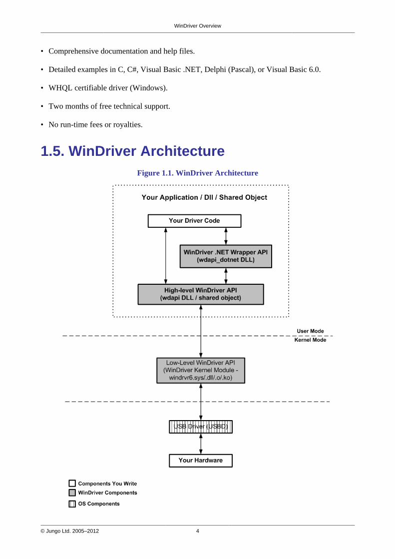
1.5. WinDriver ArchitectureFigure 1.1. WinDriver Architecture
WinDriver Overview
© Jungo Ltd. 2005–2012 5
For hardware access, your application calls one of the WinDriver user-mode functions. The user-mode function calls the WinDriver kernel, which accesses the hardware for you through thenative calls of the operating system.
1.6. What Platforms Does WinDriver Support?WinDriver supports the following operating systems:
• Windows 8/7/Vista/Server 2008/Server 2003/XP — henceforth collectively: Windows
• Windows CE (a.k.a. Windows Embedded Compact) 4.x–7.x (including Windows Mobile) —henceforth collectively: Windows CE
• Linux
The same source code will run on all supported platforms — simply recompile it for the targetplatform. The source code is binary compatible across Windows 8 / 7 / Vista / Server 2008 /Server 2003 / XP; WinDriver executables can be ported among the binary-compatible platformswithout recompilation.
Even if your code is meant only for one of the supported operating systems, using WinDriverwill give you the flexibility to move your driver to another operating system in the future withoutneeding to change your code.
1.7. Limitations of the Different EvaluationVersionsAll the evaluation versions of the WinDriver USB Host toolkit are full featured. No functions arelimited or crippled in any way. The evaluation version of WinDriver varies from the registeredversion in the following ways:
• Each time WinDriver is activated, an Unregistered message appears.
• When using DriverWizard, a dialogue box with a message stating that an evaluation version isbeing run appears on every interaction with the hardware.
• In the Linux and Windows CE versions, the driver will remain operational for 60 minutes, afterwhich time it must be restarted.
• The Windows evaluation version expires 30 days from the date of installation.
For more details please refer to Appendix D.

WinDriver Overview
© Jungo Ltd. 2005–2012 6
1.8. How Do I Develop My Driver withWinDriver?
1.8.1. On Windows and Linux
1. Start DriverWizard and use it to diagnose your hardware — see details in Chapter 5.
2. Let DriverWizard generate skeletal code for your driver, or use one of the WinDriver samplesas the basis for your driver application (see Chapter 8 for details regarding WinDriver'senhanced support for specific chipsets).
3. Modify the generated/sample code to suit your application's needs.
4. Run and debug your driver.
The code generated by DriverWizard is a diagnostics program that contains functions thatperform data transfers on the device's pipes, send requests to the control pipe, change theactive alternate setting, reset pipes, and more.
1.8.2. On Windows CE
1. Plug your hardware into a Windows host machine.
2. Diagnose your hardware using DriverWizard.
3. Let DriverWizard generate your driver's skeletal code.
4. Modify this code, using MS eMbedded Visual C++, to meet your specific needs. If you areusing MS Platform Builder, activate it and insert the generated *.pbp into your workspace.
5. Test your driver on the target embedded Windows CE platorm.
1.9. What Does the WinDriver Toolkit Include?• A printed version of this manual
• Two months of free technical support (Phone/Fax/Email)
• WinDriver modules
WinDriver Overview
© Jungo Ltd. 2005–2012 7
• The WinDriver CD
• Utilities
• Chipset support APIs
• Sample files
1.9.1. WinDriver Modules
• WinDriver (WinDriver/include) — the general purpose hardware access toolkit. The mainfiles here are:
• windrvr.h: Declarations and definitions of WinDriver's basic API.
• wdu_lib.h: Declarations and definitions of the WinDriver USB (WDU) library, whichprovides convenient wrapper USB APIs.
• windrvr_int_thread.h: Declarations of convenient wrapper functions to simplify interrupthandling.
• windrvr_events.h: Declarations of APIs for handling and Plug-and-Play and powermanagement events.
• utils.h: Declarations of general utility functions.
• status_strings.h: Declarations of API for converting WinDriver status codes to descriptiveerror strings.
• DriverWizard (WinDriver/wizard/wdwizard) — a graphical application that diagnosesyour hardware and enables you to easily generate code for your driver (refer to Chapter 5 fordetails).
• Debug Monitor — a debugging tool that collects information about your driver as it runs. Thistool is available both as a fully graphical application — WinDriver/util/wddebug_gui — andas a console-mode application — WinDriver/util/wddebug. The console-mode version alsosupports GUI execution on Windows CE platforms that don't have a command-line prompt.For details regarding the Debug Monitor, refer to Section 7.2.
• WinDriver distribution package (WinDriver/redist) — the files you include in the driverdistribution to customers.
• This manual — the full WinDriver manual (this document), in different formats, can be foundunder the WinDriver/docs directory.

WinDriver Overview
© Jungo Ltd. 2005–2012 8
1.9.2. Utilities
• usb_diag.exe (WinDriver/util/usb_diag.exe) — enables the user to view the resources ofconnected USB devices and communicate with the devices — transfer data to/from the device,set the active alternate setting, reset pipes, etc.On Windows the program identifies all devices that have been registered to work withWinDriver using an INF file. On the other supported operating systems the program identifiesall USB devices connected to the target platform.
• pci_dump.exe (WinDriver/util/pci_dump.exe) — used to obtain a dump of the PCIconfiguration registers of the installed PCI cards.
• pci_scan.exe (WinDriver/util/pci_scan.exe) — used to obtain a list of the PCI cards installedand the resources allocated for each card.
• pcmcia_diag.exe (WinDriver/util/pcmcia_diag.exe) — used for reading/writing PCMCIAattribute space, accessing PCMCIA I/O and memory ranges and handling PCMCIA interrupts.
• pcmcia_scan.exe (WinDriver/util/pcmcia_scan.exe) — used to obtain a list of the PCMCIAcards installed and the resources allocated for each card.
1.9.3. WinDriver's Specific Chipset Support
WinDriver provides custom wrapper APIs and sample code for major USB chipsets (seeChapter 8), including for the Cypress EZ-USB chipset — WinDriver/cypress.
1.9.4. Samples
In addition to the samples provided for specific chipsets [1.9.3], WinDriver includes a varietyof samples that demonstrate how to use WinDriver's API to communicate with your device andperform various driver tasks.
• C samples: found under the WinDriver/samples directory.These samples also include the source code for the utilities listed above [1.9.2].
• .NET C# and Visual Basic .NET samples (Windows): found under the WinDriver\csharp.netand WinDriver\vb.net directories (respectively).
• Delphi (Pascal) samples (Windows) WinDriver\delphi\samples directory.
• Visual Basic samples (Windows): found under the WinDriver\vb\samples directory.
WinDriver Overview
© Jungo Ltd. 2005–2012 9
1.10. Can I Distribute the Driver Created withWinDriver?Yes. WinDriver is purchased as a development toolkit, and any device driver created usingWinDriver may be distributed, royalties free, in as many copies as you wish. See the licenseagreement at (WinDriver/docs/license.pdf) for more details.

© Jungo Ltd. 2005–2012 10
Chapter 2Understanding Device DriversThis chapter provides you with a general introduction to device drivers and takes you through thestructural elements of a device driver.
Using WinDriver, you do not need to familiarize yourself with the internal workings ofdriver development. As explained in Chapter 1 of the manual, WinDriver enables you tocommunicate with your hardware and develop a driver for your device from the user mode,using only WinDriver's simple APIs, without any need for driver or kernel developmentknowledge.
2.1. Device Driver OverviewDevice drivers are the software segments that provides an interface between the operating systemand the specific hardware devices such as terminals, disks, tape drives, video cards and networkmedia. The device driver brings the device into and out of service, sets hardware parameters in thedevice, transmits data from the kernel to the device, receives data from the device and passes itback to the kernel, and handles device errors.
A driver acts like a translator between the device and programs that use the device. Each devicehas its own set of specialized commands that only its driver knows. In contrast, most programsaccess devices by using generic commands. The driver, therefore, accepts generic commandsfrom a program and then translates them into specialized commands for the device.
2.2. Classification of Drivers According toFunctionalityThere are numerous driver types, differing in their functionality. This subsection briefly describesthree of the most common driver types.
2.2.1. Monolithic Drivers
Monolithic drivers are device drivers that embody all the functionality needed to support ahardware device. A monolithic driver is accessed by one or more user applications, and directlydrives a hardware device. The driver communicates with the application through I/O controlcommands (IOCTLs) and drives the hardware using calls to the different WDK, ETK, DDI/DKIfunctions.

Understanding Device Drivers
© Jungo Ltd. 2005–2012 11
Figure 2.1. Monolithic Drivers
Monolithic drivers are supported in all operating systems including all Windows platforms and allUnix platforms.
2.2.2. Layered Drivers
Layered drivers are device drivers that are part of a stack of device drivers that together processan I/O request. An example of a layered driver is a driver that intercepts calls to the disk andencrypts/decrypts all data being transferred to/from the disk. In this example, a driver would behooked on to the top of the existing driver and would only do the encryption/decryption.
Layered drivers are sometimes also known as filter drivers, and are supported in all operatingsystems including all Windows platforms and all Unix platforms.

Understanding Device Drivers
© Jungo Ltd. 2005–2012 12
Figure 2.2. Layered Drivers
2.2.3. Miniport Drivers
A Miniport driver is an add-on to a class driver that supports miniport drivers. It is used so theminiport driver does not have to implement all of the functions required of a driver for that class.The class driver provides the basic class functionality for the miniport driver.A class driver is a driver that supports a group of devices of common functionality, such as allHID devices or all network devices.
Miniport drivers are also called miniclass drivers or minidrivers, and are supported in theWindows NT (2000) family, namely Windows 8 / 7 / Vista / Server 2008 / Server 2003 / XP /2000 / NT 4.0.
Understanding Device Drivers
© Jungo Ltd. 2005–2012 13
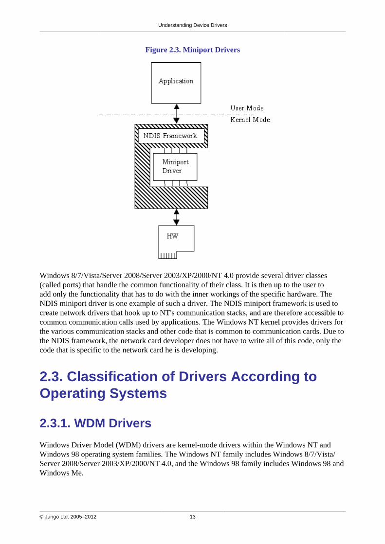
Figure 2.3. Miniport Drivers
Windows 8/7/Vista/Server 2008/Server 2003/XP/2000/NT 4.0 provide several driver classes(called ports) that handle the common functionality of their class. It is then up to the user toadd only the functionality that has to do with the inner workings of the specific hardware. TheNDIS miniport driver is one example of such a driver. The NDIS miniport framework is used tocreate network drivers that hook up to NT's communication stacks, and are therefore accessible tocommon communication calls used by applications. The Windows NT kernel provides drivers forthe various communication stacks and other code that is common to communication cards. Due tothe NDIS framework, the network card developer does not have to write all of this code, only thecode that is specific to the network card he is developing.
2.3. Classification of Drivers According toOperating Systems
2.3.1. WDM Drivers
Windows Driver Model (WDM) drivers are kernel-mode drivers within the Windows NT andWindows 98 operating system families. The Windows NT family includes Windows 8/7/Vista/Server 2008/Server 2003/XP/2000/NT 4.0, and the Windows 98 family includes Windows 98 andWindows Me.
Understanding Device Drivers
© Jungo Ltd. 2005–2012 14
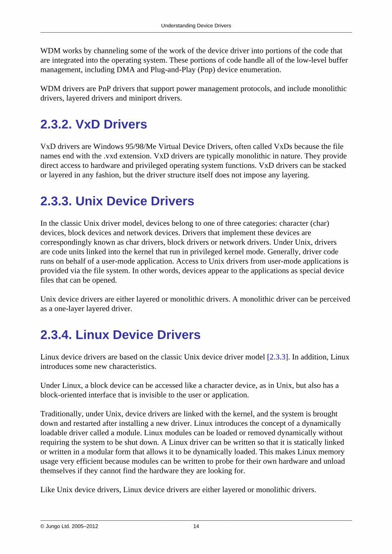
WDM works by channeling some of the work of the device driver into portions of the code thatare integrated into the operating system. These portions of code handle all of the low-level buffermanagement, including DMA and Plug-and-Play (Pnp) device enumeration.
WDM drivers are PnP drivers that support power management protocols, and include monolithicdrivers, layered drivers and miniport drivers.
2.3.2. VxD Drivers
VxD drivers are Windows 95/98/Me Virtual Device Drivers, often called VxDs because the filenames end with the .vxd extension. VxD drivers are typically monolithic in nature. They providedirect access to hardware and privileged operating system functions. VxD drivers can be stackedor layered in any fashion, but the driver structure itself does not impose any layering.
2.3.3. Unix Device Drivers
In the classic Unix driver model, devices belong to one of three categories: character (char)devices, block devices and network devices. Drivers that implement these devices arecorrespondingly known as char drivers, block drivers or network drivers. Under Unix, driversare code units linked into the kernel that run in privileged kernel mode. Generally, driver coderuns on behalf of a user-mode application. Access to Unix drivers from user-mode applications isprovided via the file system. In other words, devices appear to the applications as special devicefiles that can be opened.
Unix device drivers are either layered or monolithic drivers. A monolithic driver can be perceivedas a one-layer layered driver.
2.3.4. Linux Device Drivers
Linux device drivers are based on the classic Unix device driver model [2.3.3]. In addition, Linuxintroduces some new characteristics.
Under Linux, a block device can be accessed like a character device, as in Unix, but also has ablock-oriented interface that is invisible to the user or application.
Traditionally, under Unix, device drivers are linked with the kernel, and the system is broughtdown and restarted after installing a new driver. Linux introduces the concept of a dynamicallyloadable driver called a module. Linux modules can be loaded or removed dynamically withoutrequiring the system to be shut down. A Linux driver can be written so that it is statically linkedor written in a modular form that allows it to be dynamically loaded. This makes Linux memoryusage very efficient because modules can be written to probe for their own hardware and unloadthemselves if they cannot find the hardware they are looking for.
Like Unix device drivers, Linux device drivers are either layered or monolithic drivers.
Understanding Device Drivers
© Jungo Ltd. 2005–2012 15
2.4. The Entry Point of the DriverEvery device driver must have one main entry point, like the main() function in a C consoleapplication. This entry point is called DriverEntry() in Windows and init_module() inLinux. When the operating system loads the device driver, this driver entry procedure is called.
There is some global initialization that every driver needs to perform only once whenit is loaded for the first time. This global initialization is the responsibility of theDriverEntry()/init_module() routine. The entry function also registers which drivercallbacks will be called by the operating system. These driver callbacks are operating systemrequests for services from the driver. In Windows, these callbacks are called dispatch routines,and in Linux they are called file operations. Each registered callback is called by the operatingsystem as a result of some criteria, such as disconnection of hardware, for example.
2.5. Associating the Hardware with the DriverOperating systems differ in the ways they associate a device with a specific driver.
In Windows, the hardware-driver association is performed via an INF file, which registers thedevice to work with the driver. This association is performed before the DriverEntry() routineis called. The operating system recognizes the device, checks its database to identify which INFfile is associated with the device, and according to the INF file, calls the driver's entry point.
In Linux, the hardware-driver association is defined in the driver's init_module() routine. Thisroutine includes a callback that indicates which hardware the driver is designated to handle. Theoperating system calls the driver's entry point, based on the definition in the code.
2.6. Communicating with DriversCommunication between a user-mode application and the driver that drives the hardware,is implemented differently for each operating system, using the custom OS ApplicationProgramming Interfaces (APIs).
On Windows, Windows CE, and Linux, the application can use the OS file-access API to opena handle to the driver (e.g., using the Windows CreateFile() function or using the Linuxopen() function), and then read and write from/to the device by passing the handle to the relevantOS file-access functions (e.g., the Windows ReadFile() and WriteFile() functions, or theLinux read() and write() functions).
The application sends requests to the driver via I/O control (IOCTL) calls, using the custom OSAPIs provided for this purpose (e.g., the Windows DeviceIoControl() function, or the Linuxioctl() function).The data passed between the driver and the application via the IOCTL calls is encapsulated usingcustom OS mechanisms. For example, on Windows the data is passed via an I/O Request Packet(IRP) structure, and is encapsulated by the I/O Manager.
© Jungo Ltd. 2005–2012 16
Chapter 3WinDriver USB OverviewThis chapter explores the basic characteristics of the Universal Serial Bus (USB) and introducesWinDriver USB's features and architecture.
The references to the WinDriver USB toolkit in this chapter relate to the standardWinDriver USB toolkit for development of USB host drivers.
3.1. Introduction to USBUSB (Universal Serial Bus) is an industry standard extension to the PC architecture forattaching peripherals to the computer. It was originally developed in 1995 by leading PC andtelecommunication industry companies, such as Intel, Compaq, Microsoft and NEC. USB wasdeveloped to meet several needs, among them the needs for an inexpensive and widespreadconnectivity solution for peripherals in general and for computer telephony integration inparticular, an easy-to-use and flexible method of reconfiguring the PC, and a solution for adding alarge number of external peripherals. The USB standard meets these needs.
The USB specification allows for the connection of a maximum of 127 peripheral devices(including hubs) to the system, either on the same port or on different ports.
USB also supports Plug-and-Play installation and hot swapping. The USB 1.1 standard supportsboth isochronous and asynchronous data transfers and has dual speed data transfer: 1.5 Mb/s(megabits per second) for low-speed USB devices and 12 Mb/s for full-speed USB devices(much faster than the original serial port). Cables connecting the device to the PC can be up tofive meters (16.4 feet) long. USB includes built-in power distribution for low power devices andcan provide limited power (up to 500 mA of current) to devices attached on the bus.
The USB 2.0 standard supports a signalling rate of 480 Mb/s, known as 'high-speed', which is 40times faster than the USB 1.1 full-speed transfer rate.USB 2.0 is fully forward- and backward-compatible with USB 1.1 and uses existing cables andconnectors.USB 2.0 supports connections with PC peripherals that provide expanded functionality andrequire wider bandwidth. In addition, it can handle a larger number of peripherals simultaneously.USB 2.0 enhances the user's experience of many applications, including interactive gaming,broadband Internet access, desktop and Web publishing, Internet services and conferencing.
Because of its benefits (described also in Section 3.2 below), USB is currently enjoying broadmarket acceptance.

WinDriver USB Overview
© Jungo Ltd. 2005–2012 17
3.2. WinDriver USB BenefitsThis section describes the main benefits of the USB standard and the WinDriver USB toolkit,which supports this standard:
• External connection, maximizing ease of use
• Self identifying peripherals supporting automatic mapping of function to driver andconfiguration
• Dynamically attachable and re-configurable peripherals
• Suitable for device bandwidths ranging from a few Kb/s to hundreds of Mb/s
• Supports isochronous as well as asynchronous transfer types over the same set of wires
• Supports simultaneous operation of many devices (multiple connections)
• Supports a data transfer rate of up to 480 Mb/s (high-speed) for USB 2.0 (for the operatingsystems that officially support this standard) and up to 12 Mb/s (full-speed) for USB 1.1
• Guaranteed bandwidth and low latencies; appropriate for telephony, audio, etc. (isochronoustransfer may use almost the entire bus bandwidth)
• Flexibility: supports a wide range of packet sizes and a wide range of data transfer rates
• Robustness: built-in error handling mechanism and dynamic insertion and removal of deviceswith no delay observed by the user
• Synergy with PC industry; Uses commodity technologies
• Optimized for integration in peripheral and host hardware
• Low-cost implementation, therefore suitable for development of low-cost peripherals
• Low-cost cables and connectors
• Built-in power management and distribution
• Specific library support for custom USB HID devices
3.3. USB ComponentsThe Universal Serial Bus (USB) consists of the following primary components:
• USB Host: The USB host platform is where the USB host controller is installed and where theclient software/device driver runs. The USB Host Controller is the interface between the hostand the USB peripherals. The host is responsible for detecting the insertion and removal of

WinDriver USB Overview
© Jungo Ltd. 2005–2012 18
USB devices, managing the control and data flow between the host and the devices, providingpower to attached devices and more.
• USB Hub: A USB device that allows multiple USB devices to attach to a single USB port ona USB host. Hubs on the back plane of the hosts are called root hubs. Other hubs are calledexternal hubs.
• USB Function: A USB device that can transmit or receive data or control information over thebus and that provides a function. A function is typically implemented as a separate peripheraldevice that plugs into a port on a hub using a cable. However, it is also possible to create acompound device, which is a physical package that implements multiple functions and anembedded hub with a single USB cable. A compound device appears to the host as a hub withone or more non-removable USB devices, which may have ports to support the connection ofexternal devices.
3.4. Data Flow in USB DevicesDuring the operation of a USB device, the host can initiate a flow of data between the clientsoftware and the device.
Data can be transferred between the host and only one device at a time (peer to peercommunication). However, two hosts cannot communicate directly, nor can two USB devices(with the exception of On-The-Go (OTG) devices, where one device acts as the master (host) andthe other as the slave.)
The data on the USB bus is transferred via pipes that run between software memory buffers on thehost and endpoints on the device.
Data flow on the USB bus is half-duplex, i.e., data can be transmitted only in one direction at agiven time.
An endpoint is a uniquely identifiable entity on a USB device, which is the source or terminus ofthe data that flows from or to the device. Each USB device, logical or physical, has a collection ofindependent endpoints. The three USB speeds (low, full and high) all support one bi-directionalcontrol endpoint (endpoint zero) and 15 unidirectional endpoints. Each unidirectional endpointcan be used for either inbound or outbound transfers, so theoretically there are 30 supportedendpoints.Each endpoint has the following attributes: bus access frequency, bandwidth requirement,endpoint number, error handling mechanism, maximum packet size that can be transmitted orreceived, transfer type and direction (into or out of the device).
WinDriver USB Overview
© Jungo Ltd. 2005–2012 19
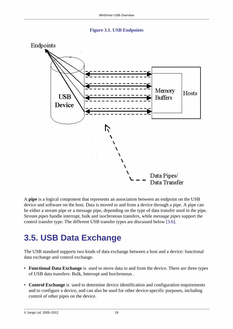
Figure 3.1. USB Endpoints
A pipe is a logical component that represents an association between an endpoint on the USBdevice and software on the host. Data is moved to and from a device through a pipe. A pipe canbe either a stream pipe or a message pipe, depending on the type of data transfer used in the pipe.Stream pipes handle interrupt, bulk and isochronous transfers, while message pipes support thecontrol transfer type. The different USB transfer types are discussed below [3.6].
3.5. USB Data ExchangeThe USB standard supports two kinds of data exchange between a host and a device: functionaldata exchange and control exchange.
• Functional Data Exchange is used to move data to and from the device. There are three typesof USB data transfers: Bulk, Interrupt and Isochronous .
• Control Exchange is used to determine device identification and configuration requirementsand to configure a device, and can also be used for other device-specific purposes, includingcontrol of other pipes on the device.

WinDriver USB Overview
© Jungo Ltd. 2005–2012 20
Control exchange takes place via a control pipe — the default pipe 0, which always exists. Thecontrol transfer consists of a setup stage (in which a setup packet is sent from the host to thedevice), an optional data stage and a status stage.
Figure 3.2 below depicts a USB device with one bi-directional control pipe (endpoint) and twofunctional data transfer pipes (endpoints), as identified by WinDriver's DriverWizard utility(discussed in Chapter 5).
Figure 3.2. USB Pipes
More information on how to implement the control transfer by sending setup packets can befound in Section 9.2.
3.6. USB Data Transfer TypesThe USB device (function) communicates with the host by transferring data through a pipebetween a memory buffer on the host and an endpoint on the device. USB supports four differenttransfer types. A type is selected for a specific endpoint according to the requirements of thedevice and the software. The transfer type of a specific endpoint is determined in the endpointdescriptor.
The USB specification provides for the following data transfer types:
WinDriver USB Overview
© Jungo Ltd. 2005–2012 21
3.6.1. Control TransferControl Transfer is mainly intended to support configuration, command and status operationsbetween the software on the host and the device.
This transfer type is used for low-, full- and high-speed devices.
Each USB device has at least one control pipe (default pipe), which provides access to theconfiguration, status and control information.
Control transfer is bursty, non-periodic communication.
The control pipe is bi-directional — i.e., data can flow in both directions.
Control transfer has a robust error detection, recovery and retransmission mechanism and retriesare made without the involvement of the driver.
The maximum packet size for control endpoints can be only 8 bytes for low-speed devices; 8, 16,32, or 64 bytes for full-speed devices; and only 64 bytes for high-speed devices.
For more in-depth information regarding USB control transfers and their implementation, refer toSection 9.2 of the manual.
3.6.2. Isochronous TransferIsochronous Transfer is most commonly used for time-dependent information, such as multimediastreams and telephony.
This transfer type can be used by full-speed and high-speed devices, but not by low-speeddevices.
Isochronous transfer is periodic and continuous.
The isochronous pipe is unidirectional, i.e., a certain endpoint can either transmit or receiveinformation. Bi-directional isochronous communication requires two isochronous pipes, one ineach direction.
USB guarantees the isochronous transfer access to the USB bandwidth (i.e., it reserves therequired amount of bytes of the USB frame) with bounded latency, and guarantees the datatransfer rate through the pipe, unless there is less data transmitted.
Since timeliness is more important than correctness in this type of transfer, no retries are made incase of error in the data transfer. However, the data receiver can determine that an error occurredon the bus.
3.6.3. Interrupt TransferInterrupt Transfer is intended for devices that send and receive small amounts of data infrequentlyor in an asynchronous time frame.
WinDriver USB Overview
© Jungo Ltd. 2005–2012 22
This transfer type can be used for low-, full- and high-speed devices.
Interrupt transfer type guarantees a maximum service period and that delivery will be re-attempted in the next period if there is an error on the bus.
The interrupt pipe, like the isochronous pipe, is unidirectional and periodical.
The maximum packet size for interrupt endpoints can be 8 bytes or less for low-speed devices; 64bytes or less for full-speed devices; and 1,024 bytes or less for high-speed devices.
3.6.4. Bulk Transfer
Bulk Transfer is typically used for devices that transfer large amounts of non-time sensitive data,and that can use any available bandwidth, such as printers and scanners.
This transfer type can be used by full-speed and high-speed devices, but not by low-speeddevices.
Bulk transfer is non-periodic, large packet, bursty communication.
Bulk transfer allows access to the bus on an "as-available" basis, guarantees the data transfer butnot the latency, and provides an error check mechanism with retries attempts. If part of the USBbandwidth is not being used for other transfers, the system will use it for bulk transfer.
Like the other stream pipes (isochronous and interrupt), the bulk pipe is also unidirectional, so bi-directional transfers require two endpoints.
The maximum packet size for bulk endpoints can be 8, 16, 32, or 64 bytes for full-speed devices,and 512 bytes for high-speed devices.
3.7. USB ConfigurationBefore the USB function (or functions, in a compound device) can be operated, the devicemust be configured. The host does the configuring by acquiring the configuration informationfrom the USB device. USB devices report their attributes by descriptors. A descriptor is thedefined structure and format in which the data is transferred. A complete description of the USBdescriptors can be found in Chapter 9 of the USB Specification (see http://www.usb.org for thefull specification).
It is best to view the USB descriptors as a hierarchical structure with four levels:
• The Device level
• The Configuration level
• The Interface level (this level may include an optionalsub-level called Alternate Setting)
WinDriver USB Overview
© Jungo Ltd. 2005–2012 23
• The Endpoint level
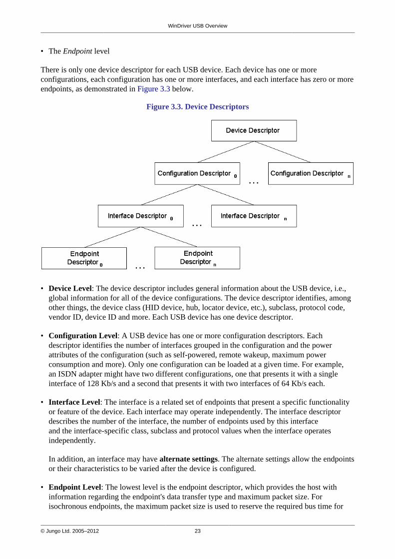
There is only one device descriptor for each USB device. Each device has one or moreconfigurations, each configuration has one or more interfaces, and each interface has zero or moreendpoints, as demonstrated in Figure 3.3 below.
Figure 3.3. Device Descriptors
• Device Level: The device descriptor includes general information about the USB device, i.e.,global information for all of the device configurations. The device descriptor identifies, amongother things, the device class (HID device, hub, locator device, etc.), subclass, protocol code,vendor ID, device ID and more. Each USB device has one device descriptor.
• Configuration Level: A USB device has one or more configuration descriptors. Eachdescriptor identifies the number of interfaces grouped in the configuration and the powerattributes of the configuration (such as self-powered, remote wakeup, maximum powerconsumption and more). Only one configuration can be loaded at a given time. For example,an ISDN adapter might have two different configurations, one that presents it with a singleinterface of 128 Kb/s and a second that presents it with two interfaces of 64 Kb/s each.
• Interface Level: The interface is a related set of endpoints that present a specific functionalityor feature of the device. Each interface may operate independently. The interface descriptordescribes the number of the interface, the number of endpoints used by this interfaceand the interface-specific class, subclass and protocol values when the interface operatesindependently.
In addition, an interface may have alternate settings. The alternate settings allow the endpointsor their characteristics to be varied after the device is configured.
• Endpoint Level: The lowest level is the endpoint descriptor, which provides the host withinformation regarding the endpoint's data transfer type and maximum packet size. Forisochronous endpoints, the maximum packet size is used to reserve the required bus time for
WinDriver USB Overview
© Jungo Ltd. 2005–2012 24
the data transfer — i.e., the bandwidth. Other endpoint attributes are its bus access frequency,endpoint number, error handling mechanism and direction. The same endpoint can havedifferent properties (and consequently different uses) in different alternate settings.
Seems complicated? Not at all! WinDriver automates the USB configuration process. Theincluded DriverWizard utility [5] and USB diagnostics application scan the USB bus, detect allUSB devices and their configurations, interfaces, alternate settings and endpoints, and enable youto pick the desired configuration before starting driver development.
WinDriver identifies the endpoint transfer type as determined in the endpoint descriptor. Thedriver created with WinDriver contains all configuration information acquired at this early stage.
3.8. WinDriver USBWinDriver USB enables developers to quickly develop high-performance drivers for USB-baseddevices without having to learn the USB specifications and operating system internals, or usethe operating system development kits. For example, Windows drivers can be developed withoutusing the Windows Driver Kit (WDK) or learning the Windows Driver Model (WDM).
The driver code developed with WinDriver USB is binary compatible across the supportedWindows platforms — Windows 8/7/Vista/Server 2008/Server 2003/XP — and source codecompatible across all supported operating systems — Windows 8 / 7 / Vista / Server 2008 /Server 2003 / XP, Windows CE (a.k.a. Windows Embedded Compact) 4.x–7.x (includingWindows Mobile), and Linux. For an up-to-date list of supported operating systems, visit Jungo'sweb site — http://www.jungo.com.
WinDriver USB is a generic tool kit that supports all USB devices from all vendors and with alltypes of configurations.
WinDriver USB encapsulates the USB specification and architecture, letting you focus on yourapplication logic. WinDriver USB features the graphical DriverWizard utility [5], which enablesyou to easily detect your hardware, view its configuration information, and test it, before writinga single line of code: DriverWizard first lets you choose the desired configuration, interfaceand alternate setting combination, using a friendly graphical user interface. After detecting andconfiguring your USB device, you can proceed to test the communication with the device —perform data transfers on the pipes, send control requests, reset the pipes, etc. — in order toensure that all your hardware resources function as expected.
After your hardware is diagnosed, you can use DriverWizard to automatically generate yourdevice driver source code in C, C#, Visual Basic .NET, Delphi (Pascal), or Visual Basic 6.0.WinDriver USB provides user-mode APIs, which you can call from within your application inorder to implement the communication with your device. The WinDriver USB API includesUSB-unique operations such as reset of a pipe or a device. The generated DriverWizard codeimplements a diagnostics application, which demonstrates how to use WinDriver's USB API todrive your specific device. In order to use the application you just need to compile and run it. Youcan jump-start your development cycle by using this application as your skeletal driver and thenmodifying the code, as needed, to implement the desired driver functionality for your specificdevice.

WinDriver USB Overview
© Jungo Ltd. 2005–2012 25
DriverWizard also automates the creation of an INF file that registers your device to work withWinDriver, which is an essential step in order to correctly identify and handle USB devicesusing WinDriver. For an explanation on why you need to create an INF file for your USB device,refer to Section 12.1.1 of the manual. For detailed information on creation of INF files withDriverWizard, refer to Section 5.2 (see specifically Step 3).
With WinDriver USB, all development is done in the user mode, using familiar development anddebugging tools and your favorite compiler or development environment (such as MS VisualStudio, Borland C++ Builder, Borland Delphi, Visual Basic 6.0, MS eMbedded Visual C++, MSPlatform Builder C++, GCC, Windows GCC).
For more information regarding implementation of USB transfers with WinDriver, refer toChapter 9 of the manual.
3.9. WinDriver USB ArchitectureTo access your hardware, your application calls the WinDriver kernel module using functionsfrom the WinDriver USB API. The high-level functions utilize the low-level functions, whichuse IOCTLs to enable communication between the WinDriver kernel module and your user-mode application. The WinDriver kernel module accesses your USB device resources through thenative operating system calls.
There are two layers responsible for abstracting the USB device to the USB device driver. Theupper layer is the USB Driver (USBD) layer, which includes the USB Hub Driver and the USBCore Driver. The lower level is the Host Controller Driver (HCD) layer. The division of dutiesbetween the HCD and USBD layers is not defined and is operating system dependent. Both theHCD and USBD are software interfaces and components of the operating system, where the HCDlayer represents a lower level of abstraction.
The HCD is the software layer that provides an abstraction of the host controller hardware, whilethe USBD provides an abstraction of the USB device and the data transfer between the hostsoftware and the function of the USB device.
The USBD communicates with its clients (the specific device driver, for example) throughthe USB Driver Interface (USBDI). At the lower level, the Core Driver and USB Hub Driverimplement the hardware access and data transfer by communicating with the HCD using the HostController Driver Interface (HCDI).
The USB Hub Driver is responsible for identifying the addition and removal of devices from aparticular hub. When the Hub Driver receives a signal that a device was attached or detached, ituses additional host software and the USB Core Driver to recognize and configure the device. Thesoftware implementing the configuration can include the hub driver, the device driver, and othersoftware.
WinDriver USB abstracts the configuration procedure and hardware access described abovefor the developer. With WinDriver's USB API, developers can perform all the hardware-related operations without having to master the lower-level implementation for supporting theseoperations.
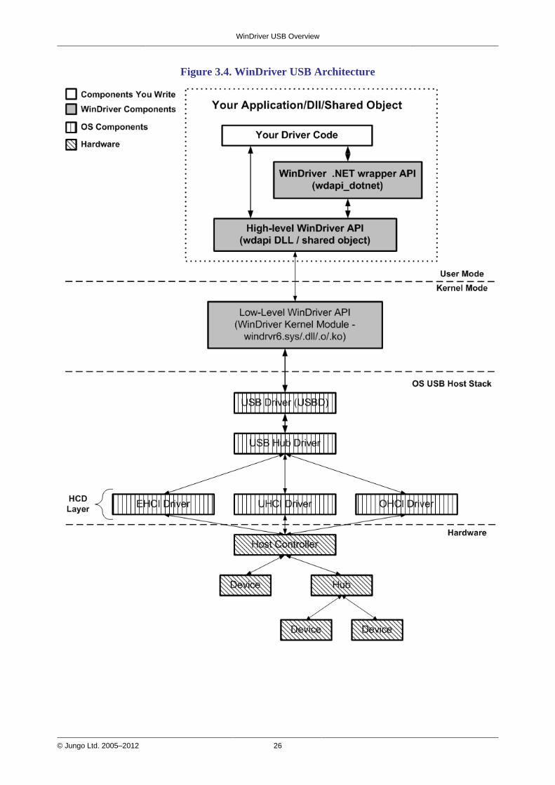
WinDriver USB Overview
© Jungo Ltd. 2005–2012 26
Figure 3.4. WinDriver USB Architecture
© Jungo Ltd. 2005–2012 27
Chapter 4Installing WinDriverThis chapter takes you through the process of installing WinDriver on your developmentplatform, and shows you how to verify that your WinDriver is properly installed. The last sectiondiscusses the uninstall procedure. To find out how to install the driver you create on targetplatforms, refer to Chapter 11.
4.1. System Requirements
4.1.1. Windows System Requirements
• Any x86 32-bit or 64-bit (x64: AMD64 or Intel EM64T) processor
• Any compiler or development environment supporting C, .NET, VB, or Delphi
• Windows XP requires at least SP2
4.1.2. Windows CE System Requirements
• An x86, MIPS, or ARM target platform running Windows CE (a.k.a. Windows EmbeddedCompact) 4.x–7.x (including Windows Mobile)
• Windows 8/7/Vista/Server 2008/Server 2003/XP host development platform
• IDE:
For Windows CE 4.x–5.x (including Windows Mobile):
Microsoft eMbedded Visual C++ or Microsoft Visual Studio 2005/2008, with acorresponding target SDK
ORMicrosoft Platform Builder with a corresponding Board Support Package (BSP) for thetarget platform
For Windows CE 6.x: Microsoft Visual Studio 2005/2008 with a corresponding target SDKor with the Windows CE 6.0 plugin
For Windows CE 7.x: Microsoft Visual Studio 2008 with the Windows CE 7 plugin

Installing WinDriver
© Jungo Ltd. 2005–2012 28
4.1.3. Linux System Requirements
• Any of the following processor architectures, with a 2.6.x or higher Linux kernel:
32-bit x86
64-bit x86 AMD64 or Intel EM64T (x86_64)
Jungo strives to support new Linux kernel versions as close as possible to their release.To find out the latest supported kernel version, refer to the WinDriver release notes(found online at http://www.jungo.com/st/wdver.html).
• A GCC compiler
The version of the GCC compiler should match the compiler version used for buildingthe running Linux kernel.
• Any 32-bit or 64-bit development environment (depending on your target configuration)supporting C for user mode
• On your development PC: glibc2.3.x
• libstdc++.so.5 — required for running GUI WinDriver applications (e.g., DriverWizard [5];Debug Monitor [7.2])
4.2. WinDriver Installation ProcessThe WinDriver CD contains all versions of WinDriver for the supported operating systems. TheCD's root directory contains the Windows version. The installation of this version will beginautomatically when you insert the CD into the CD drive on your Windows development machine.The other versions of WinDriver are located in <OS> subdirectories (for example: Linux;Wince).
4.2.1. Windows WinDriver Installation Instructions
Driver installation on Windows requires administrator privileges.
1. Insert the WinDriver CD into your CD-ROM drive, or double-click the downloadedinstallation file — WD1110.EXE — and follow the installation instructions.
When using the installation CD, wait a few seconds for the installation to beginautomatically. If this does not happen, double-click the file WD1110.EXE in the CD,and click the Install WinDriver button.
2. At the end of the installation, you may be prompted to reboot your computer.
Installing WinDriver
© Jungo Ltd. 2005–2012 29
• The WinDriver installation defines a WD_BASEDIR environment variable, which is set topoint to the location of your WinDriver directory, as selected during the installation. Thisvariable is used during the DriverWizard [5] code generation — it determines the defaultdirectory for saving your generated code and is used in the include paths of the generatedproject/make files.
• If the installation fails with an ERROR_FILE_NOT_FOUND error, inspect the Windowsregistry to see if the RunOnce key exists in HKEY_LOCAL_MACHINE\SOFTWARE\Microsoft\Windows\CurrentVersion. This registry key is required byWindows Plug-and-Play in order to properly install drivers using INF files. If theRunOnce key is missing, create it; then try installing the INF file again.
The following steps are for registered users only:
To register your copy of WinDriver with the license you received from Jungo, follow these steps:
3. Start DriverWizard: Start | Programs | WinDriver | DriverWizard.
4. Select the Register WinDriver option from the File menu, and insert the license string youreceived from Jungo.
5. Click the Activate License button.
6. To register source code that you developed during the evaluation period, refer to thedocumentation of WDU_Init() [B.4.1].
4.2.2. Windows CE WinDriver InstallationInstructions
4.2.2.1. Installing WinDriver CE when Building NewCE-Based Platforms
• The following instructions apply to platform developers who build Windows CE kernelimages using Windows CE Platform Builder or using MS Visual Studio 2005/2008 withthe appropriate Windows CE plugin. The instructions use the notation 'Windows CEIDE' to refer to either of these platforms.
• We recommend that you read Microsoft's documentation and understand the WindowsCE and device driver integration procedure before you perform the installation.
1. Modify the project registry file to add an entry for your target device:
• If you select to use the WinDriver component (refer to Step 2), modifyWinDriver\samples\wince_install\<TARGET_CPU>\WinDriver.reg (e.g.,WinDriver\samples\wince_install\ARMV4I\WinDriver.reg).
• Otherwise, modify WinDriver\samples\wince_install\project_wd.reg.
Installing WinDriver
© Jungo Ltd. 2005–2012 30
2. For Windows CE 4.x–5.x only, you can simplify the driver integration into your WindowsCE platform by following the procedure described in this step, before the Sysgen platformcompilation stage.
Note:
• Developers who use Windows CE 6.x and higher should skip to the next step (Step 3).
• This procedure provides a convenient method for integrating WinDriver into yourWindows CE platform. If you select not to use this method, you will need to perform themanual integration steps described in Step 4 below, after the Sysgen stage.
• The procedure described in this step also adds the WinDriver kernel module(windrvr6.dll) to your OS image. This is a necessary step if you want the WinDriver CEkernel file (windrvr6.dll) to be a permanent part of the Windows CE image (NK.BIN),which is the case if you select to transfer the file to your target platform using a boot disk.However, if you prefer to have the file windrvr6.dll loaded on demand via the CESH/PPSH services, you need to perform the manual integration method described in Step 4instead of performing the procedure described in the present step.
a. Run the Windows CE IDE and open your platform.
b. From the File menu select Manage Catalog Items...., click theImport... button, and select the WinDriver.cec file from the relevantWinDriver\samples\wince_install\<TARGET_CPU> directory (e.g.,WinDriver\samples\wince_install\ARMV4I). This will add a WinDriver component tothe Platform Builder Catalog.
c. In the Catalog view, right-click the mouse on the WinDriver Component node in theThird Party tree, and select Add to OS design.
3. Compile your Windows CE platform (Sysgen stage).
4. If you did not perform the procedure described in Step 2 above, perform the following stepsafter the Sysgen stage in order to manually integrate the driver into your platform.Note: If you followed the procedure described in Step 2, skip this step and go directly toStep 5.
a. Run the Windows CE IDE and open your platform.
b. Select Open Release Directory from the Build menu.
c. Copy the WinDriver CE kernel file —WinDriver\redist\<TARGET_CPU>\windrvr6.dll — to the%_FLATRELEASEDIR% subdirectory on the target development platform (should bethe current directory in the new command window).
d. Append the contents of WinDriver\samples\wince_install\project_wd.reg to the%_FLATRELEASEDIR%\project.reg registry file.
Installing WinDriver
© Jungo Ltd. 2005–2012 31
e. Copy the contents of the WinDriver\samples\wince_install\project_wd.bibfile to the FILES section of the binary image builder file —%_FLATRELEASEDIR%\project.bib. Then uncomment the line that matches thetarget platform (see the "TODO" comments in the copied text).
This step is only necessary if you want the WinDriver CE kernel file(windrvr6.dll) to be a permanent part of the Windows CE image (NK.BIN),which is the case if you select to transfer the file to your target platform usinga boot disk. If you prefer to have the file windrvr6.dll loaded on demand viathe CESH/PPSH services, you do not need to perform this step until you build apermanent kernel.
5. Select Make Run-Time Image from the Build menu, and name the new image NK.BIN.
6. Download your new kernel to the target platform and initialize it either by selectingAttach Device from the Target menu, or by using a boot disk. For Windows CE 4.x, themenu is called Download/Initialize rather than Attach Device.
7. Restart your target CE platform. The WinDriver CE kernel will automatically load.
8. Compile and run the sample programs to make sure that WinDriver CE is loaded and isfunctioning correctly (see Section 4.4.2, which describes how to check your installation).
4.2.2.2. Installing WinDriver CE when DevelopingApplications for Windows CE Computers
Unless otherwise specified, 'Windows CE' references in this section include all supportedWindows CE platforms, including Windows Mobile.
The following instructions apply to driver developers who do not build the Windows CE kernel,but only download their drivers, built using MS eMbedded Visual C++ or MS Visual Studio2005/2008 to a ready-made Windows CE platform.
1. Insert the WinDriver CD into your Windows host CD drive.
2. Exit the automatic installation.
3. Copy WinDriver's kernel module — windrvr6.dll — from theWinDriver\redist\WINCE\<TARGET_CPU> directory on the Windows host developmentPC to the Windows directory on your target Windows CE platform.

Installing WinDriver
© Jungo Ltd. 2005–2012 32
4. Add WinDriver to the list of device drivers Windows CE loads on boot:
• Modify the registry according to the entries documented in the fileWinDriver\samples\wince_install\project_wd.reg. This can be done using the WindowsCE Pocket Registry Editor on the hand-held CE computer, or by using the Remote CERegistry Editor Tool supplied with MS eMbedded Visual C++ or MS Visual Studio2005/2008. Note that in order to use the Remote CE Registry Editor tool you will need tohave Windows CE Services installed on your Windows host platform.
• On many versions of Windows CE, the operating system's security scheme prevents theloading of unsigned drivers at boot time, therefore the WinDriver kernel module has tobe reloaded after boot. To load WinDriver on the target Windows CE platform every timethe OS is started, copy the WinDriver\redist\Windows_Mobile_5_ARMV4I\wdreg.exeutility to the Windows\StartUp directory on the target PC.
5. Restart your target CE computer. The WinDriver CE kernel will automatically load. You willhave to do a warm reset rather than just suspend/resume (use the reset or power button onyour target CE computer).
6. Compile and run the sample programs to make sure that WinDriver CE is loaded and isfunctioning correctly (see Section 4.4, which describes how to check your installation).
4.2.2.3. Windows CE Installation Note
The WinDriver installation on the host Windows 8 / 7 / Vista / Server 2008 / Server 2003 /XP PC defines a WD_BASEDIR environment variable, which is set to point to the location ofyour WinDriver directory, as selected during the installation. This variable is used during theDriverWizard [5] code generation — it determines the default directory for saving your generatedcode, and is used in the include paths of the generated project/make files.
Note that if you install the WinDriver Windows toolkit on the same host PC, the installation willoverride the value of the WD_BASEDIR variable from the Windows CE installation.
4.2.3. Linux WinDriver Installation Instructions
4.2.3.1. Preparing the System for Installation
In Linux, kernel modules must be compiled with the same header files that the kernel itself wascompiled with. Since WinDriver installs kernel modules, it must compile with the header files ofthe Linux kernel during the installation process.
Therefore, before you install WinDriver for Linux, verify that the Linux source code and the fileversions.h are installed on your machine:
Installing WinDriver
© Jungo Ltd. 2005–2012 33
Install the Linux kernel source code:
• If you have yet to install Linux, install it, including the kernel source code, by following theinstructions for your Linux distribution.
• If Linux is already installed on your machine, check whether the Linux source code wasinstalled. You can do this by looking for 'linux' in the /usr/src directory. If the source codeis not installed, either install it, or reinstall Linux with the source code, by following theinstructions for your Linux distribution.
Install version.h:
• The file version.h is created when you first compile the Linux kernel source code.Some distributions provide a compiled kernel without the file version.h. Look under/usr/src/linux/include/linux to see whether you have this file. If you do not, follow these steps:
1. Become super user:$ su
2. Change directory to the Linux source directory:# cd /usr/src/linux
3. Type:# make xconfig
4. Save the configuration by choosing Save and Exit.
5. Type:# make dep
6. Exit super user mode:# exit
To run GUI WinDriver applications (e.g., DriverWizard [5]; Debug Monitor [7.2]) you must alsohave version 5.0 of the libstdc++ library — libstdc++.so.5. If you do not have this file, install itfrom the relevant RPM in your Linux distribution (e.g., compat-libstdc++).
Before proceeding with the installation, you must also make sure that you have a linux symboliclink. If you do not, create one by typing/usr/src$ ln -s <target kernel>/linuxFor example, for the Linux 2.4 kernel type/usr/src$ ln -s linux-2.4/ linux
Installing WinDriver
© Jungo Ltd. 2005–2012 34
4.2.3.2. Installation
If your development machine is running a Debian distribution (e.g., Ubuntu) or has the Red HatPackage Manager (RPM) utility (used, e.g., in Red Hat distributions such as Fedora), you canuse the provided Debian or RPM WinDriver installation package (respectively) to automate theWinDriver installation, as outlined in Section 4.2.3.2.1. Otherwise, follow the manual installationprocess in Section 4.2.3.2.2, which is supported for all Linux distributions.
4.2.3.2.1. Installation using a Debian or RPM Installation Package
To install WinDriver using one of the Debian or RPM WinDriver installation packages, followthese steps:
1. Insert the WinDriver CD into your Linux machine's CD drive, or copy the downloaded file toyour preferred directory.
2. Extract the relevant distribution package for your development machine from the WinDriverinstallation file — WD1110LN.tgz or WD1110LNx86_64.tgz:
• Debian 32-bit — windriver-11.1.0-1.i386.deb
• Debian 64-bit — windriver-11.1.0-1.x86_64.deb
• RPM 32-bit — windriver-11.1.0-2.i386.rpm
• RPM 64-bit — windriver-11.1.0-2.x86_64.rpm
3. Use your selected package installer software to install the extracted package.
• On most machines, *.deb files (Debian) and *.rpm files (RPM) are alreadyassociated with the relevant installation software, so you can simply double-click thepackage file and follow the installation instructions.
• You may also install the package from the command-line, using root privileges —for example:
To install the 32-bit Debian package —# sudo dpkg -i windriver-11.1.0-1.i386.deb
To install the 64-bit RPM package —# sudo rpm -i --scripts windriver-11.1.0-2.x86_64.rpm
The package installation will create a /usr/local/WinDriver product directory.
4.2.3.2.2. Manual Installation
1. Insert the WinDriver CD into your Linux machine's CD drive, or copy the downloaded file toyour preferred directory.

Installing WinDriver
© Jungo Ltd. 2005–2012 35
2. Change directory to your preferred installation directory, for example to your home directory:$ cd ~
The path to the installation directory must not contain any spaces.
3. Extract the WinDriver distribution file — WD1110LN.tgz or WD1110LNx86_64.tgz —$ tar xvzf <file location>/WD1110LN[x86_64].tgz
For example, to extract WD1110LN.tgz
• From a CD —$ tar xvzf /mnt/cdrom/LINUX/WD1110LN.tgz
• From a downloaded file —$ tar xvzf ~/WD1110LN.tgz
4. Change directory to your WinDriver redist directory (the tar automatically creates aWinDriver directory):$ cd <WinDriver directory path>/redist
5. Install WinDriver:
a. <WinDriver directory>/redist$ ./configure
• The configuration script creates a makefile based on the running kernel. Youmay select to use another installed kernel source, by executing the script withthe --with-kernel-source=<path> option, where <path> is the fullpath to the kernel source directory — e.g., /usr/src/linux.
• If the Linux kernel version is 2.6.26 or higher, the configuration script generatesmakefiles that use kbuild to compile the kernel modules. You can force the useof kbuild on earlier versions of Linux, by executing the configuration scriptwith the --enable-kbuild flag.
For a full list of the configuration script options, use the --help option:./configure --help
b. <WinDriver directory>/redist$ make
c. Become super user:<WinDriver directory>/redist$ su
d. Install the driver:<WinDriver directory>/redist# make install
6. Create a symbolic link so that you can easily launch the DriverWizard GUI:$ ln -s <path to WinDriver>/wizard/wdwizard /usr/bin/wdwizard

Installing WinDriver
© Jungo Ltd. 2005–2012 36
7. Change the read and execute permissions on the file wdwizard so that ordinary users canaccess this program.
8. Change the user and group IDs and give read/write permissions to the device file/dev/windrvr6, depending on how you wish to allow users to access hardwarethrough the device. Due to security reasons, by default the device file is createdwith permissions only for the root user. Change the permissions by modifying your/etc/udev/permissions.d/50-udev.permissions file. For example, add the following line toprovide read and write permissions:windrvr6:root:root:0666
9. Define a new WD_BASEDIR environment variable and set it to point to the location of yourWinDriver directory, as selected during the installation. This variable is used in the make andsource files of the WinDriver samples and generated DriverWizard [5] code, and is also usedto determine the default directory for saving your generated DriverWizard projects. If you donot define this variable you will be instructed to do so when attempting to build the sample/generated code using the WinDriver makefiles.
10. Exit super user mode:# exit
11. You can now start using WinDriver to access your hardware and generate your driver code!
Use the WinDriver/util/wdreg script to load the WinDriver kernel module [10.3].
4.2.3.2.3. Registering Your WinDriver License
This section applies only to registered WinDriver users.
To register your copy of WinDriver with the license you received from Jungo, follow these steps:
1. Start DriverWizard:$ <path to WinDriver>/wizard/wdwizard
2. Select the Register WinDriver option from the File menu, and insert the license string youreceived from Jungo.
3. Click the Activate License button.
4. To register source code that you developed during the evaluation period, refer to thedocumentation of WDU_Init() [B.4.1].
Installing WinDriver
© Jungo Ltd. 2005–2012 37
4.2.3.3. Restricting Hardware Access on Linux
Since /dev/windrvr6 gives direct hardware access to user programs, it may compromisekernel stability on multi-user Linux systems. Please restrict access to DriverWizard and thedevice file /dev/windrvr6 to trusted users.
For security reasons the WinDriver installation script does not automatically perform thesteps of changing the permissions on /dev/windrvr6 and the DriverWizard application(wdwizard).
4.3. Upgrading Your InstallationTo upgrade to a new version of WinDriver on Windows, follow the steps outlined inSection 4.2.1, which illustrate the process of installing WinDriver for Windows. You can eitherchoose to overwrite the existing installation or install to a separate directory.
After installation, start DriverWizard and enter the new license string, if you have received one.This completes the upgrade of WinDriver.
To upgrade your source code, pass the new license string as a parameter to WDU_Init() [B.4.1](or to WD_License(), when using the old WD_UsbXXX() APIs).
The procedure for upgrading your installation on other operating systems is the same as the onedescribed above. Please check the respective installation sections for installation details.
4.4. Checking Your Installation
4.4.1. Windows and Linux Installation Check
1. Start DriverWizard — <path to WinDriver>/wizard/wdwizard. On Windows you can alsorun DriverWizard from the Start menu: Start | Programs | WinDriver | DriverWizard.
2. If you are a registered user, make sure that your WinDriver license is registered (refer toSection 4.2, which explains how to install WinDriver and register your license).If you are an evaluation version user, you do not need to register a license.
Installing WinDriver
© Jungo Ltd. 2005–2012 38
4.4.2. Windows CE Installation Check
1. Copy the console-mode Debug Monitor utility —WinDriver\util\wddebug\<TARGET_CPU>\wddebug.exe — from the host Windowsmachine to a directory on your target Windows CE device.
2. Run the Debug Monitor with the status command on the target device:wddebug.exe statusIf the WinDriver installation was successful, the application will display informationregarding the Debug Monitor version and current status, the running WinDriver kernelmodule, and general system information.
4.5. Uninstalling WinDriverThis section will help you to uninstall either the evaluation or registered version of WinDriver.
4.5.1. Windows WinDriver Uninstall Instructions
• You can select to use the graphical wdreg_gui.exe utility instead of wdreg.exe.
• wdreg.exe and wdreg_gui.exe are found in the WinDriver\util directory (see Chapter 10for details regarding these utilities).
1. Close any open WinDriver applications, including DriverWizard, the Debug Monitor, anduser-specific applications.
2. Uninstall all Plug-and-Play devices (USB/PCI/PCMCIA) that have been registered withWinDriver via an INF file:
• Uninstall the device using the wdreg utility:wdreg -inf <path to the INF file> uninstall
• Verify that no INF files that register your device(s) with WinDriver's kernel module(windrvr6.sys) are found in the %windir%\inf directory.
Installing WinDriver
© Jungo Ltd. 2005–2012 39
3. Uninstall WinDriver:
• On the development PC, on which you installed the WinDriver toolkit:Run Start | WinDriver | Uninstall , OR run the uninstall.exe utility from the WinDriverinstallation directory.
The uninstall will stop and unload the WinDriver kernel module (windrvr6.sys); delete thecopy of the windrvr6.inf file from the %windir%\inf directory; delete WinDriver fromWindows' Start menu; delete the WinDriver installation directory (except for files thatyou added to this directory); and delete the shortcut icons to the DriverWizard and DebugMonitor utilities from the Desktop.
• On a target PC, on which you installed the WinDriver kernel module (windrvr6.sys), butnot the entire WinDriver toolkit:Use the wdreg utility to stop and unload the driver:wdreg -inf <path to windrvr6.inf> uninstall
When running this command, windrvr6.sys should reside in the same directory aswindrvr6.inf.
(On the development PC, the relevant wdreg uninstall command is executed for you by theuninstall utility).
• If you attempt to uninstall WinDriver while there are open handles to the WinDriverservice (windrvr6.sys or your renamed driver [12.2], or there are connected andenabled Plug-and-Play devices that are registered to work with this service, wdregwill fail to uninstall the driver. This ensures that you do not uninstall the driver whileit is being used.
• You can check if the WinDriver kernel module is loaded by running the DebugMonitor utility (WinDriver\util\wddebug_gui.exe) [7.2]. When the driver is loaded,the Debug Monitor log displays driver and OS information; otherwise, it displays arelevant error message. On the development PC, the uninstall command will deletethe Debug Monitor executables; to use this utility after the uninstallation, create acopy of wddebug_gui.exe before performing the uninstall procedure.
4. If windrvr6.sys was successfully unloaded, erase the following files (if they exist):
• %windir%\system32\drivers\windrvr6.sys
• %windir%\inf\windrvr6.inf
• %windir%\system32\wdapi1110.dll
• %windir%\sysWOW64\wdapi1110.dll (Windows x64)
5. Reboot the computer.

Installing WinDriver
© Jungo Ltd. 2005–2012 40
4.5.2. Linux WinDriver Uninstall Instructions
The following commands must be executed with root privileges.
1. Verify that the WinDriver driver modules are not being used by another program:
• View the list of modules and the programs using each of them:# /sbin/lsmod
• Identify any applications and modules that are using the WinDriver driver modules. (Bydefault, WinDriver module names begin with windrvr6).
• Close any applications that are using the WinDriver driver modules.
2. Uninstall WinDriver —
• If you installed WinDriver using one of the WinDriver Debian or RPM installationpackages [4.2.3.2.1], you can uninstall (remove) it using the Linux Software Center, orfrom the command line, using root privileges — for example:
To uninstall the 32-bit Debian package —# sudo dpkg -r windriver-11.1.0-1.i386To uninstall the 64-bit RPM package —# sudo rpm -e --scripts windriver-11.1.0-2.x86_64
• If you installed WinDriver manually [4.2.3.2.2], run the following command to unload theWinDriver driver modules:# /sbin/modprobe -r windrvr6
3. Remove the file .windriver.rc from the /etc directory:# rm -f /etc/.windriver.rc
4. Remove the file .windriver.rc from $HOME:# rm -f $HOME/.windriver.rc
5. If you created a symbolic link to DriverWizard, remove the link using the command# rm -f /usr/bin/wdwizard
6. Remove the WinDriver installation directory using the command# rm -rf <path to the WinDriver directory>(for example: # rm -rf /usr/local/WinDriver).
7. Remove the WinDriver shared object file, if it exists:/usr/lib/libwdapi1110.so (32-bit x86) //usr/lib64/libwdapi1110.so (64-bit x86).

© Jungo Ltd. 2005–2012 41
Chapter 5Using DriverWizardThis chapter describes WinDriver DriverWizard's hardware diagnostics and driver codegeneration capabilities.
5.1. An OverviewDriverWizard (included in the WinDriver toolkit) is a GUI-based diagnostics and drivergeneration tool that allows you to write to and read from the hardware, before writing a singleline of code. The hardware is diagnosed through a Graphical User Interface — the device'sconfiguration and pipes information is displayed, data can be transferred on the pipes, the pipescan be reset, etc.
Once the device is operating to your satisfaction, DriverWizard creates the skeletal driver sourcecode, with functions to access your hardware's resources.
If you are developing a driver for a device that is based on one of the enhanced-support USBchipsets (the Cypress EZ-USB family), we recommend that you read Chapter 8, which explainsWinDriver's enhanced support for specific chipsets, before starting your driver development.
DriverWizard can be used to diagnose your hardware; on Windows it can also be used to generatean INF file for your hardware.
Avoid using DriverWizard to generate code for a device based on one of the supported USBchipsets [8], as DriverWizard generates generic code which will have to be modified accordingto the specific functionality of the device in question. Preferably, use the complete source codelibraries and sample applications (supplied in the package) tailored to the various USB chipsets.
DriverWizard is an excellent tool for two major phases in your HW/Driver development:
• Hardware diagnostics: After the hardware has been built, attach your device to a USB port onyour machine, and use DriverWizard to verify that the hardware is performing as expected.
• Code generation: Once you are ready to build your code, let DriverWizard generate yourdriver code for you.
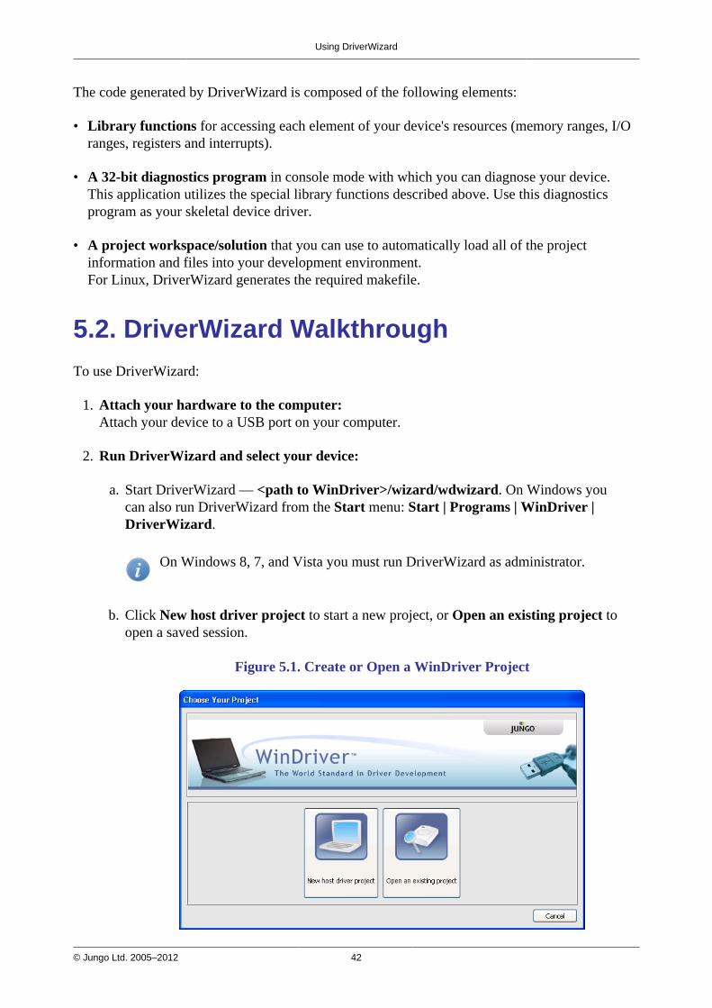
Using DriverWizard
© Jungo Ltd. 2005–2012 42
The code generated by DriverWizard is composed of the following elements:
• Library functions for accessing each element of your device's resources (memory ranges, I/Oranges, registers and interrupts).
• A 32-bit diagnostics program in console mode with which you can diagnose your device.This application utilizes the special library functions described above. Use this diagnosticsprogram as your skeletal device driver.
• A project workspace/solution that you can use to automatically load all of the projectinformation and files into your development environment.For Linux, DriverWizard generates the required makefile.
5.2. DriverWizard WalkthroughTo use DriverWizard:
1. Attach your hardware to the computer:Attach your device to a USB port on your computer.
2. Run DriverWizard and select your device:
a. Start DriverWizard — <path to WinDriver>/wizard/wdwizard. On Windows youcan also run DriverWizard from the Start menu: Start | Programs | WinDriver |DriverWizard.
On Windows 8, 7, and Vista you must run DriverWizard as administrator.
b. Click New host driver project to start a new project, or Open an existing project toopen a saved session.
Figure 5.1. Create or Open a WinDriver Project

Using DriverWizard
© Jungo Ltd. 2005–2012 43
c. Select your Device from the list of devices detected by DriverWizard.
Figure 5.2. Select Your Device
3. Generate an INF file for DriverWizard:On Windows 8/7/Vista/Server 2008/Server 2003/XP, the driver for Plug-and-Play devices(such as USB) is installed by installing an INF file for the device. DriverWizard enablesyou to generate an INF file that registers your device to work with WinDriver (i.e., with thewindrvr6.sys driver). The INF file generated by DriverWizard should later be distributed toyour customers who are using Windows 8 / 7 / Vista / Server 2008 / Server 2003 / XP, andinstalled on their PCs.
The INF file that you generate in this step is also designed to enable DriverWizard todiagnose Plug-and-Play devices on Windows 8 / 7 / Vista / Server 2008 / Server 2003 / XP.Additional information concerning the need for an INF file is provided in Section 12.1.1.
If you do not need to generate an INF file, skip this step and proceed to the next one.
To generate the INF file with DriverWizard, follow the steps below:
a. In the Select Your Device screen, click the Generate .INF file button or click Next .
b. DriverWizard will display information detected for your device — Vendor ID, ProductID, Device Class, manufacturer name and device name — and allow you to modify thisinformation.

Using DriverWizard
© Jungo Ltd. 2005–2012 44
Figure 5.3. DriverWizard INF File Information
c. For multiple-interface USB devices, you can select to generate an INF file either for thecomposite device or for a specific interface.
• When selecting to generate an INF file for a specific interface of a multi-interfaceUSB device the INF information dialogue will indicate for which interface the INF fileis generated.
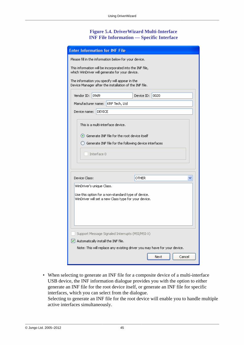
Using DriverWizard
© Jungo Ltd. 2005–2012 45
Figure 5.4. DriverWizard Multi-InterfaceINF File Information — Specific Interface
• When selecting to generate an INF file for a composite device of a multi-interfaceUSB device, the INF information dialogue provides you with the option to eithergenerate an INF file for the root device itself, or generate an INF file for specificinterfaces, which you can select from the dialogue.Selecting to generate an INF file for the root device will enable you to handle multipleactive interfaces simultaneously.
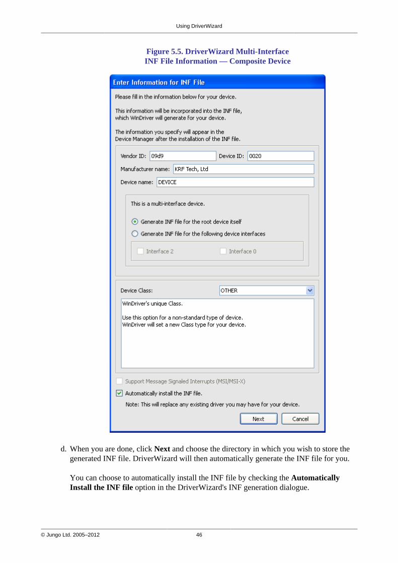
Using DriverWizard
© Jungo Ltd. 2005–2012 46
Figure 5.5. DriverWizard Multi-InterfaceINF File Information — Composite Device
d. When you are done, click Next and choose the directory in which you wish to store thegenerated INF file. DriverWizard will then automatically generate the INF file for you.
You can choose to automatically install the INF file by checking the AutomaticallyInstall the INF file option in the DriverWizard's INF generation dialogue.
Using DriverWizard
© Jungo Ltd. 2005–2012 47
If the automatic INF file installation fails, DriverWizard will notify you and providemanual installation instructions (refer also the manual INF file installation instructions inSection 12.1).
e. When the INF file installation completes, select and open your device from the list in theSelect Your Device screen.
4. Uninstall the INF file of your device:You can use the Uninstall option to uninstall the INF file of your device. Once you uninstallthe INF file, the device will no longer be registered to work with the windrvr6.sys, and theINF file will be deleted from the Windows root directory. If you do not need to uninstall anINF file, skip this step and proceed to the next one.
a. In the Select Your Device screen, click the Uninstall .INF file button.
b. Select the INF file to be removed.
5. Select the desired alternate setting:
DriverWizard detects all the device's supported alternate settings and displays them, asdemonstrated in Figure 5.6 below.Select the desired alternate setting from the displayed list.
DriverWizard will display the pipes information for the selected alternate setting.
For USB devices with only one alternate setting configured, DriverWizardautomatically selects the detected alternate setting and therefore the Select DeviceInterface dialogue will not be displayed.
6. Diagnose your device:Before writing your device driver, it is important to make sure your hardware is working asexpected. Use DriverWizard to diagnose your hardware. All of your activity will be logged inthe DriverWizard log so that you may later analyze your tests:
a. Test your USB device's pipes: DriverWizard shows the pipes detected for the selectedalternate setting. To perform USB data transfers on the pipes, follow these steps:

Using DriverWizard
© Jungo Ltd. 2005–2012 48
Figure 5.6. Select Device Interface
i. Select the desired pipe.
ii. For a control pipe (a bidirectional pipe), click Read / Write. A new dialogue willappear, allowing you to select a standard USB request or define a custom request, asdemonstrated in Figure 5.7.
Figure 5.7. USB Control Transfers
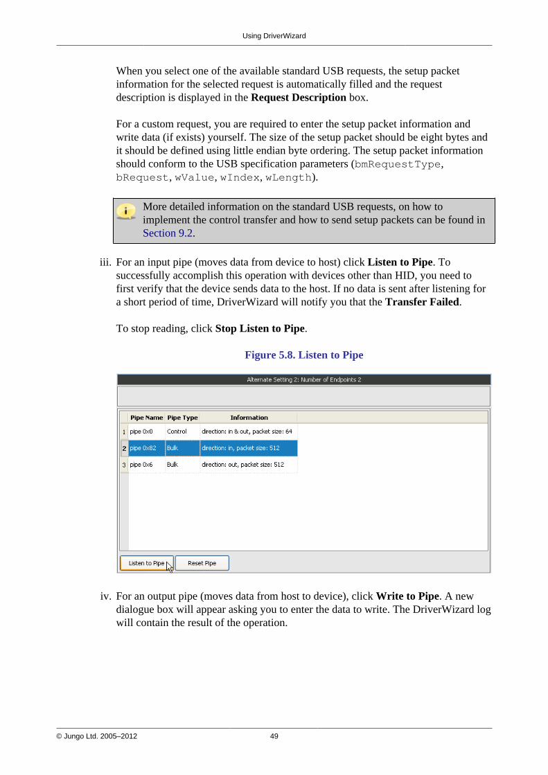
Using DriverWizard
© Jungo Ltd. 2005–2012 49
When you select one of the available standard USB requests, the setup packetinformation for the selected request is automatically filled and the requestdescription is displayed in the Request Description box.
For a custom request, you are required to enter the setup packet information andwrite data (if exists) yourself. The size of the setup packet should be eight bytes andit should be defined using little endian byte ordering. The setup packet informationshould conform to the USB specification parameters (bmRequestType,bRequest, wValue, wIndex, wLength).
More detailed information on the standard USB requests, on how toimplement the control transfer and how to send setup packets can be found inSection 9.2.
iii. For an input pipe (moves data from device to host) click Listen to Pipe. Tosuccessfully accomplish this operation with devices other than HID, you need tofirst verify that the device sends data to the host. If no data is sent after listening fora short period of time, DriverWizard will notify you that the Transfer Failed.
To stop reading, click Stop Listen to Pipe.
Figure 5.8. Listen to Pipe
iv. For an output pipe (moves data from host to device), click Write to Pipe. A newdialogue box will appear asking you to enter the data to write. The DriverWizard logwill contain the result of the operation.

Using DriverWizard
© Jungo Ltd. 2005–2012 50
Figure 5.9. Write to Pipe
v. You can reset input and output pipes by pressing the Reset Pipe button for theselected pipe.
7. Generate the skeletal driver code:
a. Select to generate code either via the Generate Code toolbar icon or from the Project |Generate Code menu.
b. In the Select Code Generation Options dialogue box that will appear, choose the codelanguage and development environment(s) for the generated code and select Next togenerate the code.
Figure 5.10. Code Generation Options
Using DriverWizard
© Jungo Ltd. 2005–2012 51
c. Save your project (if required) and click OK to open your development environmentwith the generated driver.
d. Close DriverWizard.
8. Compile and run the generated code:
• Use this code as a starting point for your device driver. Modify where needed to performyour driver's specific functionality.
• The source code DriverWizard creates can be compiled with any 32-bit compiler, and willrun on all supported platforms without modification.
For detailed compilation instructions, refer to Section 5.2.2.
5.2.1. Automatic Code Generation
After you have finished diagnosing your device and have ensured that it runs according to yourspecifications, you are ready to write your driver.
5.2.1.1. Generating the Code
Generate code by selecting this option either via DriverWizard's Generate Code toolbar iconor from the wizard's Project | Generate Code menu. DriverWizard will generate the sourcecode for your driver, and place it along with the project file (xxx.wdp, where "xxx" is theproject name). The files are saved in a directory DriverWizard creates for every developmentenvironment and operating system selected in the code generation dialogue box.
5.2.1.2. The Generated USB C Code
In the source code directory you now have a new xxx_diag.c source file (where xxx is the nameyou selected for your DriverWizard project). This file implements a diagnostic USB application,which demonstrates how to use WinDriver's USB API to locate and communicate with yourUSB device(s), including detection of Plug-and-Play events (device insertion/removal, etc.),performing read/write transfers on the pipes, resetting the pipes and changing the device's activealternate setting.The generated application supports handling of multiple identical USB devices.
5.2.1.3. The Generated Visual Basic and Delphi Code
The generated DriverWizard Visual Basic and Delphi code includes similar functions andprovides similar functionality as the generated C code described in Section 5.2.1.2.
The generated Delphi code implements a console application (like the C code), while theVisual Basic code implements a GUI application.

Using DriverWizard
© Jungo Ltd. 2005–2012 52
5.2.1.4. The Generated C# and Visual Basic .NET Code
The generated DriverWizard C# and Visual Basic .NET code provides similar functionality as thegenerated C code [5.2.1.2], but from a GUI .NET program.
5.2.2. Compiling the Generated Code
5.2.2.1. Windows and Windows CE Compilation
As explained above, on Windows you can select to generate project, workspace/solution, andmake files for the supported compilers and development environments — MS Visual Studio5.0/6.0/2003/2005/2008/2010, Borland C++ Builder, Visual Basic 6.0, Borland Delphi, WindowsGCC (MinGW/Cygwin), MS eMbedded Visual C++, or MS Platform Builder.For integrated development environments (IDEs), such as MS Visual Studio, you can also selectto automatically invoke your selected IDE from the wizard. You can then proceed to immediatelybuild and run the code from your selected IDE.
You can also build the generated code using any other compiler or development environment thatsupports the selected code language and target OS. Simply create a new project or make file foryour selected compiler/environment, include the generated source files, and run the code.
• For Windows, the generated compiler/environment files are located under an x86directory — for 32-bit projects — or an amd64 directory — for 64-bit projects.
• For Windows CE, note that the generated Windows Mobile code is targeted at theWindows Mobile 5.0/6.0 ARMV4I SDK.
5.2.2.2. Linux Compilation
Use the makefile that was created for you by DriverWizard in order to build the generated codeusing your favorite compiler, preferably GCC.
5.2.3. Bus Analyzer Integration — Ellisys VisualUSB
DriverWizard provides native support for the Ellisys Explorer 200 USB analyzer on Windows XPand higher (32-bit only). This support enables you to:
• Initiate USB traffic capture directly from DriverWizard.
• Capture discrete control transfers.

Using DriverWizard
© Jungo Ltd. 2005–2012 53
To capture USB traffic:
1. Select Tools | Start USB Analyzer Capture to start capturing USB data.
2. To finish the data capture, select Tools | Stop USB Analyzer Capture.A dialogue box will appear notifying you where DriverWizard stored the analyzer trace.Click Yes to run Ellisys's Visual Analyzer with the captured data.
To capture a discrete control trasfer check the Trace USB transaction in Ellisys Visual USBcheck box in the control transfers dialogue box.
Figure 5.11. Ellisys Visual USB Integration
© Jungo Ltd. 2005–2012 54
Chapter 6Developing a DriverThis chapter takes you through the WinDriver driver development cycle.
If your device is based on one of the chipsets for which WinDriver provides enhancedsupport (the Cypress EZ-USB family), read the following overview and then skip straight toChapter 8.
6.1. Using DriverWizard to Build a DeviceDriver• Use DriverWizard to diagnose your device: View the device's configuration information,
transfer data on the device's pipes, send standard requests to the control pipe and reset thepipes. Verify that your device operates as expected.
• Use DriverWizard to generate skeletal code for your device in C, C#, Visual Basic .NET,Delphi (Pascal), or Visual Basic 6.0. For more information about DriverWizard, refer toChapter 5.
• If you are using one of the specific chipsets for which WinDriver offers enhanced support(the Cypress EZ-USB family), we recommend that you use the specific sample code providedfor your chip as your skeletal driver code. For more details regarding WinDriver's enhancedsupport for specific chipsets, refer to Chapter 8.
• Use any C / .NET / Delphi / Visual Basic compiler or development environment (depending onthe code you created) to build the skeletal driver you need.WinDriver provides specific support for the following environments and compilers: MS VisualStudio, Borland C++ Builder, Borland Delphi, Visual Basic 6.0, MS eMbedded Visual C++,MS Platform Builder C++, GCC, Windows GCC
• That is all you need to do in order to create your user-mode driver.
Please see Appendix B for a detailed description of WinDriver's USB API.For more information regarding implementation of USB transfers with WinDriver, refer toChapter 9 of the manual.

Developing a Driver
© Jungo Ltd. 2005–2012 55
6.2. Writing the Device Driver WithoutDriverWizardThere may be times when you choose to write your driver directly, without using DriverWizard.In such cases, either follow the steps outlined in this section to create a new driver project, or useone of the WinDriver samples, which most closely resembles your target driver, and modify thesample to suit your specific requirements.
6.2.1. Include the Required WinDriver Files
1. Include the relevant WinDriver header files in your driver project.All header files are found under the WinDriver/include directory.
All WinDriver projects require the windrvr.h header file.When using the WDU_xxx WinDriver USB API [B.2], include the wdu_lib.h header file;(this file already includes windrvr.h).
Include any other header file that provides APIs that you wish to use from your code (e.g.,files from the WinDriver/samples/shared directory, which provide convenient diagnosticsfunctions.)
2. Include the relevant header files from your source code: For example, to use the USB APIfrom the wdu_lib.h header file, add the following line to the code:
#include "wdu_lib.h"
3. Link your code with the WDAPI library (Windows) / shared object (Linux):
• For Windows: WinDriver\lib\<CPU>\wdapi1110.lib or wdapi1110_borland.lib (forBorland C++ Builder), where the <CPU> directory is either x86 (32-bit binaries for x86platforms), amd64 (64-bit binaries for x64 platforms) or amd64\x86 (32-bit binaries forx64 platforms [A.2]
• For Windows CE: WinDriver\lib\WINCE\<CPU>\wdapi1110.lib
• For Linux: From the WinDriver/lib directory — libwdapi1110.so or libwdapi1110_32.so(for 32-bit applications targeted at 64-bit platforms)Note: When using libwdapi1110_32.so, first create a copy of this file in a differentdirectory and rename it to libwdapi1110.so, then link your code with the renamedfile [A.2].
You can also include the library's source files in your project instead of linking the projectwith the library. The C source files are located under the WinDriver/src/wdapi directory.

Developing a Driver
© Jungo Ltd. 2005–2012 56
When linking your project with the WDAPI library/shared object, you will need todistribute this binary with your driver.For Windows, get wdapi1110.dll / wdapi1110_32.dll (for 32-bit applications targetedat 64-bit platforms) from the WinDriver\redist directory.For Linux, get libwdapi1110.so / libwdapi1110_32.so (for 32-bit applications targetedat 64-bit platforms) from the WinDriver/lib directory.
Note: On Windows and Linux, when using the DLL/shared object file for 32-bit applicationson 64-bit platforms (wdapi1110_32.dll / libwdapi1110_32.so), rename the copy of the file inthe distribution package, by removing the _32 portion [A.2].For detailed distribution instructions, refer to Chapter 11.
4. Add any other WinDriver source files that implement API that you which to use in your code(e.g., files from the WinDriver/samples/shared directory.)
6.2.2. Write Your Code
1. Call WDU_Init() [B.4.1] at the beginning of your program to initialize WinDriver for yourUSB device, and wait for the device-attach callback. The relevant device information will beprovided in the attach callback.
2. Once the attach callback is received, you can start using one of theWDU_Transfer() [B.4.8.1] functions family to send and receive data.
3. To finish, call WDU_Uninit() [B.4.7] to unregister from the device.
6.2.3. Configure and Build Your Code
After including the required files and writing your code, make sure that the required build flagsand environment variables are set, then build your code.
Before building your code, verify that the WD_BASEDIR environment variable is set to thelocation of the of the WinDriver installation directory.On Windows, Windows CE, and Linux you can define the WD_BASEDIR environmentvariable globally — as explained in Chapter 4: For Windows — refer to the WindowsWD_BASEDIR note in Section 4.2.1; for Windows CE — refer to Section 4.2.2.3; forLinux: refer to Section 4.2.3.2, Step 9.

Developing a Driver
© Jungo Ltd. 2005–2012 57
6.3. Developing Your Driver on Windows CEPlatformsTo use WinDriver to handle a Plug-and-Play device, you must first register the device with theWinDriver kernel module (windrvr6.dll).
To register the device with WinDriver, use either of the following methods:
• Modify the registry to identify your device and link it to windrvr6.dll. The registry can bemodified by adding the relevant information to your project.reg file.
To identify the device by its vendor ID (<VID>) and product ID (<PID>) — as decimalvalues — add the following:[HKEY_LOCAL_MACHINE\Drivers\USB\LoadClients\<VID>_<PID>\Default\Default\WDR] "DLL"="windrvr6.dll"
To identify the device by its USB class (<CLASS>), subclass (<SUBCLASS>), and protocol(<PROT>) — as decimal values — add the following:[HKEY_LOCAL_MACHINE\Drivers\USB\LoadClients\Default\Default\<CLASS>_<SUBCLASS>_<PROT>\WDR] "DLL"="windrvr6.dll"
• Call WDU_Init() to identify the device by its vendor and product IDs and register it withWinDriver, before connecting the device to the computer .
For more information about the relevant registry settings, refer to USB Driver RegistrySettings in the MSDN Library.

Developing a Driver
© Jungo Ltd. 2005–2012 58
6.4. Developing in Visual Basic and DelphiThe entire WinDriver API can be used when developing drivers in Visual Basic and Delphi.
6.4.1. Using DriverWizard
DriverWizard can be used to diagnose your hardware and verify that it is working properly beforeyou start coding. You can then proceed to automatically generate source code with the wizard in avariety of languages, including Delphi and Visual Basic. For more information, refer to Chapter 5and Section 6.4.3 below.
6.4.2. Samples
Samples for drivers written using the WinDriver API in Delphi or Visual Basic can be found in:
1. WinDriver\delphi\samples
2. WinDriver\vb\samples
Use these samples as a starting point for your own driver.
6.4.3. Creating your Driver
The method of development in Visual Basic is the same as the method in C using the automaticcode generation feature of DriverWizard.
Your work process should be as follows:
• Use DriverWizard to easily diagnose your hardware.
• Verify that it is working properly.
• Generate your driver code.
• Integrate the driver into your application.
• You may find it useful to use the WinDriver samples to get to know the WinDriver API and asyour skeletal driver code.

© Jungo Ltd. 2005–2012 59
Chapter 7Debugging DriversThe following sections describe how to debug your hardware-access application code.
7.1. User-Mode Debugging• Since WinDriver is accessed from the user mode, we recommend that you first debug your
code using your standard debugging software.
• The Debug Monitor utility [7.2] logs debug messages from WinDriver's kernel-mode and user-mode APIs. You can also use WinDriver APIs to send your own debug messages to the DebugMonitor log.
• Use DriverWizard to validate your device's USB configuration and test the communicationwith the device.
7.2. Debug MonitorDebug Monitor is a powerful graphical- and console-mode tool for monitoring all activitieshandled by the WinDriver kernel.You can use this tool to monitor how each command sent to the kernel is executed.
In addition, WinDriver enables you to print your own debug messages to the Debug Monitor,using the WD_DebugAdd() function [B.6.6] or the high-level PrintDbgMessage()function [B.7.14].
The Debug Monitor comes in two versions:
• wddebug_gui [7.2.1] — a GUI version for Windows and Linux.
• wddebug [7.2.2] — a console-mode version for Windows, Windows CE, and Linux; onWindows CE, wddebug also supports GUI execution.
Both Debug Monitor versions are provided in the WinDriver/util directory.
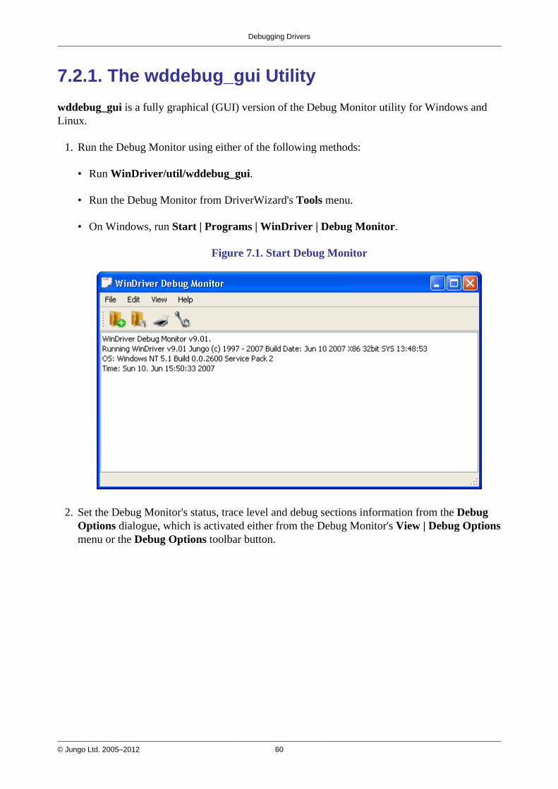
Debugging Drivers
© Jungo Ltd. 2005–2012 60
7.2.1. The wddebug_gui Utility
wddebug_gui is a fully graphical (GUI) version of the Debug Monitor utility for Windows andLinux.
1. Run the Debug Monitor using either of the following methods:
• Run WinDriver/util/wddebug_gui.
• Run the Debug Monitor from DriverWizard's Tools menu.
• On Windows, run Start | Programs | WinDriver | Debug Monitor.
Figure 7.1. Start Debug Monitor
2. Set the Debug Monitor's status, trace level and debug sections information from the DebugOptions dialogue, which is activated either from the Debug Monitor's View | Debug Optionsmenu or the Debug Options toolbar button.
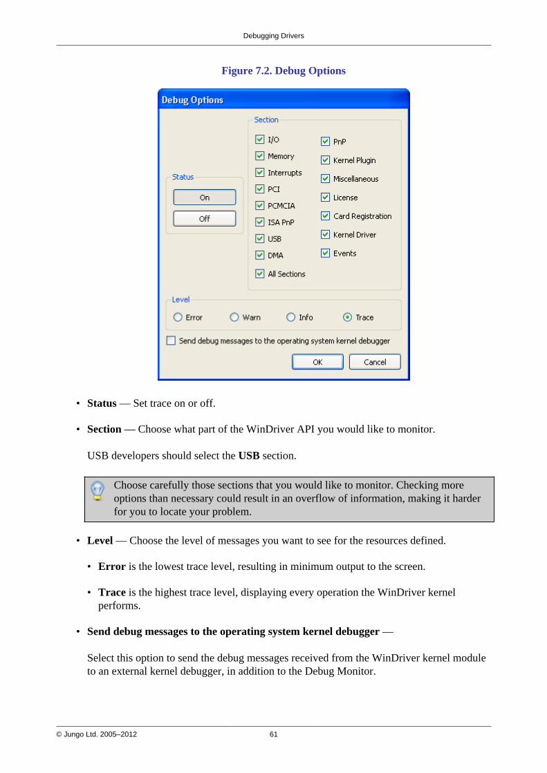
Debugging Drivers
© Jungo Ltd. 2005–2012 61
Figure 7.2. Debug Options
• Status — Set trace on or off.
• Section — Choose what part of the WinDriver API you would like to monitor.
USB developers should select the USB section.
Choose carefully those sections that you would like to monitor. Checking moreoptions than necessary could result in an overflow of information, making it harderfor you to locate your problem.
• Level — Choose the level of messages you want to see for the resources defined.
• Error is the lowest trace level, resulting in minimum output to the screen.
• Trace is the highest trace level, displaying every operation the WinDriver kernelperforms.
• Send debug messages to the operating system kernel debugger —
Select this option to send the debug messages received from the WinDriver kernel moduleto an external kernel debugger, in addition to the Debug Monitor.
Debugging Drivers
© Jungo Ltd. 2005–2012 62
On Windows 8, 7, and Vista, the first time that you enable this option you will needto restart the PC.
A free Windows kernel debugger, WinDbg, is distributed with the Windows DriverKit (WDK) and is part of the Debugging Tools for Windows package, distributed viathe Microsoft web site.
3. Once you have defined what you want to trace and on what level, click OK to close theDebug Options window.
4. Activate your application (step-by-step or in one run).
5. Watch the Debug Monitor log (or the kernel debugger log, if enabled) for errors or anyunexpected messages.
7.2.1.1. Running wddebug_gui for a Renamed Driver
By default, wddebug_gui logs messages from the default WinDriver kernel module —windrvr6.sys/.o/.ko. However, you can also use wddebug_gui to log debug messages from arenamed version of this driver [12.2], by running wddebug_gui from the command line with thedriver_name option: wddebug_gui <driver_name>.
The driver name should be set to the name of the driver file without the file's extension;e.g., windrvr6, not windrvr6.sys (on Windows) or windrvr6.o (on Linux).
For example, if you have renamed the default windrvr6.sys driver on Windows tomy_driver.sys, you can log messages from your driver by running the Debug Monitor using thefollowing command: wddebug_gui my_driver
7.2.2. The wddebug Utility
7.2.2.1. Console-Mode wddebug Execution
The wddebug version of the Debug Monitor utility can be executed as a console-modeapplication on all supported operating systems: Windows, Windows CE, and Linux. To use theconsole-mode Debug Monitor version, run WinDriver/util/wddebug in the manner explainedbelow.
For console-mode execution on Windows CE, start a command window (CMD.EXE) onthe Windows CE target, and then run the program WDDEBUG.EXE inside this shell.You can also execute wddebug via the Windows CE GUI, as explained in Section 7.2.2.2.
Debugging Drivers
© Jungo Ltd. 2005–2012 63
wddebug console-mode usage
wddebug [<driver_name>] [<command>] [<level>][<sections>]
The wddebug arguments must be provided in the order in which they appear in the usagestatement above.
• <driver_name>: The name of the driver to which to apply the command.
The driver name should be set to the name of the WinDriver kernel module — windrvr6, or arenamed version of this driver (refer to the explanation in Section 12.2).
The driver name should be set to the name of the driver file without the file's extension;for example, windrvr6, not windrvr6.sys (on Windows) or windrvr6.o (on Linux).
• <command>: The Debug Monitor command to execute:
• Activation commands:
• on: Turn the Debug Monitor on.
• off: Turn the Debug Monitor off.
• dbg_on : Redirect the debug messages from the Debug Monitor to a kernel debugger andturn the Debug Monitor on (if it was not already turned on).
On Windows 8, 7, and Vista, the first time that you enable this option you willneed to restart the PC.
• dbg_off : Stop redirecting debug messages from the Debug Monitor to a kerneldebugger.
The on and dbg_on commands can be run together with the <level> and<sections> options, described below.
• dump: Continuously display ('dump') debug information, until the user selects to stop.
• status: Display information regarding the running <driver_name> driver, the currentDebug Monitor status — including the active debug level and sections (when the DebugMonitor is on) — and the size of the debug messages buffer.
• help : Display usage instructions.
• None: You can run wddebug with no arguments, including no command. On platforms otherthan Windows CE, this is equivalent to running wddebug help. On Windows CE, runningwddebug with no arguments activates the utility's Windows CE GUI version, as explainedin Section 7.2.2.2.
Debugging Drivers
© Jungo Ltd. 2005–2012 64
The following options are applicable only to the on and dbg_on commands:
• <level>: The debug trace level to set. The level can be set to either of the following flags:ERROR, WARN, INFO or TRACE, where ERROR is the lowest trace level and TRACE is thehighest level (displays all messages).The default debug trace level is TRACE.
• <sections>: The debug sections to set. The debug sections determine what part of theWinDriver API you would like to monitor.
For a full list of all supported debug sections, run wddebug help to view the utility's usageinstructions.The default debug sections flag is ALL — sets all the supported debug sections.
Usage Sequence
To log messages using wddebug, use the following sequence:
• Turn on the Debug Monitor by running wddebug with either the on command, or the dbg_oncommand — which redirects the debug messages to a kernel debugger before turning on theDebug Monitor.
You can use the level and/or sections flags to set the debug level and/or sections for thelog. If these options are not explicitly set, the default values will be used.
You can also log messages from a renamed WinDriver driver by preceding the command withthe name of the driver (see the <driver_name> option above). The default driver name iswindrvr6.
• Run wddebug with the dump command to begin dumping debug messages to the commandprompt. You can turn off the display of the debug messages, at any time, by following theinstructions displayed in the command prompt.
• Run applications that use the driver, and view the debug messages as they are being logged tothe command prompt/the kernel debugger.
• You can run wddebug with the status command, at any time while the Debug Monitor ison, to view the current debug level and sections, as well as information regarding the running<driver_name> kernel module.
• You can use dbg_on and dbg_off to toggle the redirection of debug messages to a kerneldebugger at any time while the Debug Monitor is on.
• When you are ready, turn off the Debug Monitor by running wddebug with the off command.
You can also run wddebug with the status command while the Debug Monitor is turnedoff, to view information regarding the running <driver_name> driver.
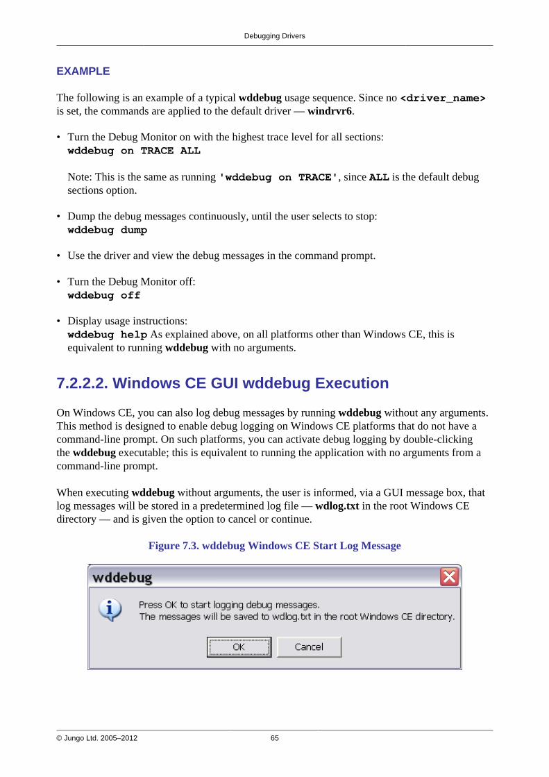
Debugging Drivers
© Jungo Ltd. 2005–2012 65
EXAMPLE
The following is an example of a typical wddebug usage sequence. Since no <driver_name>is set, the commands are applied to the default driver — windrvr6.
• Turn the Debug Monitor on with the highest trace level for all sections:wddebug on TRACE ALL
Note: This is the same as running 'wddebug on TRACE', since ALL is the default debugsections option.
• Dump the debug messages continuously, until the user selects to stop:wddebug dump
• Use the driver and view the debug messages in the command prompt.
• Turn the Debug Monitor off:wddebug off
• Display usage instructions:wddebug help As explained above, on all platforms other than Windows CE, this isequivalent to running wddebug with no arguments.
7.2.2.2. Windows CE GUI wddebug Execution
On Windows CE, you can also log debug messages by running wddebug without any arguments.This method is designed to enable debug logging on Windows CE platforms that do not have acommand-line prompt. On such platforms, you can activate debug logging by double-clickingthe wddebug executable; this is equivalent to running the application with no arguments from acommand-line prompt.
When executing wddebug without arguments, the user is informed, via a GUI message box, thatlog messages will be stored in a predetermined log file — wdlog.txt in the root Windows CEdirectory — and is given the option to cancel or continue.
Figure 7.3. wddebug Windows CE Start Log Message
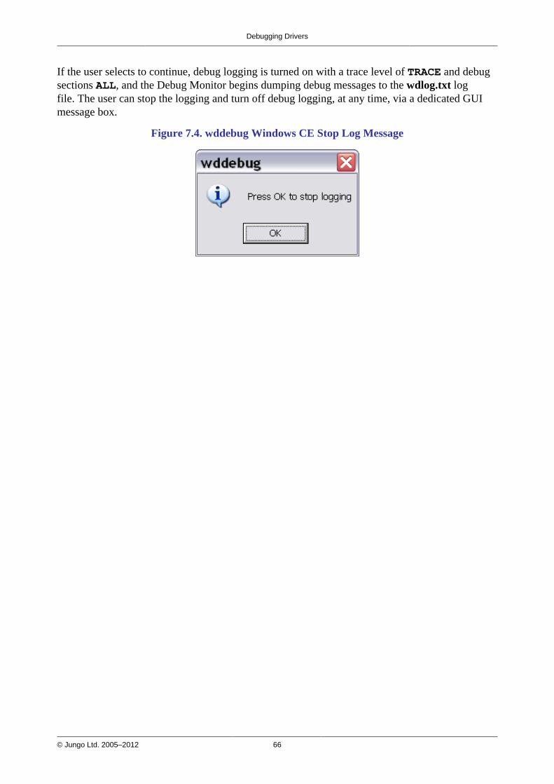
Debugging Drivers
© Jungo Ltd. 2005–2012 66
If the user selects to continue, debug logging is turned on with a trace level of TRACE and debugsections ALL, and the Debug Monitor begins dumping debug messages to the wdlog.txt logfile. The user can stop the logging and turn off debug logging, at any time, via a dedicated GUImessage box.
Figure 7.4. wddebug Windows CE Stop Log Message

© Jungo Ltd. 2005–2012 67
Chapter 8Enhanced Support for SpecificChipsets
8.1. OverviewIn addition to the standard WinDriver API and the DriverWizard code generation capabilitiesdescribed in this manual, which support development of drivers for any USB device, WinDriveroffers enhanced support for specific USB chipsets. The enhanced support includes custom APIand sample diagnostics code, which are designed specifically for these chipsets.
WinDriver's enhanced support is currently available for the Cypress EZ-USB family.
8.2. Developing a Driver Using the EnhancedChipset SupportWhen developing a driver for a device based on one of the enhanced-support chipsets [8.1], youcan use WinDriver's chipset-set specific support by following these steps:
1. Locate the sample diagnostics program for your device under the WinDriver/chip_vendor/chip_name directory.
Most of the sample diagnostics program names are derived from the sample's main purpose(e.g., download_sample for a firmware download sample) and their source code can befound directly under the specific chip_name directory.
2. Run the custom diagnostics program to diagnose your device and familiarize yourself withthe options provided by the sample program.
3. Use the source code of the diagnostics program as your skeletal device driver and modify thecode, as needed, to suit your specific development needs. When modifying the code, you canutilize the custom WinDriver API for your specific chip. The custom API is typically foundunder the WinDriver/chip_vendor/lib directory.

© Jungo Ltd. 2005–2012 68
Chapter 9USB Transfers
9.1. OverviewThis chapter provides detailed information regarding implementation of USB transfers usingWinDriver.
As explained in Section 3.5, the USB standard supports two kinds of data exchange between thehost and the device — control exchange and functional data exchange.The WinDriver APIs enable you to implement both control and functional data transfers.
Figure 9.1 demonstrates how a device's pipes are displayed in the DriverWizard utility, whichenables you to perform transfers from a GUI environment.
Figure 9.1. USB Data Exchange
Section 9.2 below provides detailed information regarding USB control transfers and how theycan be implemented using WinDriver.
Section 9.3 describes the functional data transfer implementation options provided by WinDriver.
USB Transfers
© Jungo Ltd. 2005–2012 69
9.2. USB Control Transfers
9.2.1. USB Control Transfers Overview
9.2.1.1. Control Data Exchange
USB control exchange is used to determine device identification and configuration requirementsand to configure a device, and can also be used for other device-specific purposes, includingcontrol of other pipes on the device.Control exchange takes place via a control pipe — the default pipe 0, which always exists. Thecontrol transfer consists of a setup stage (in which a setup packet is sent from the host to thedevice), an optional data stage and a status stage.
9.2.1.2. More About the Control Transfer
The control transaction always begins with a setup stage. The setup stage is followed by zero ormore control data transactions (data stage) that carry the specific information for the requestedoperation, and finally a status transaction completes the control transfer by returning the status tothe host.
During the setup stage, an 8-byte setup packet is used to transmit information to the controlendpoint of the device (endpoint 0). The setup packet's format is defined by the USBspecification.
A control transfer can be a read transaction or a write transaction. In a read transaction the setuppacket indicates the characteristics and amount of data to be read from the device. In a writetransaction the setup packet contains the command sent (written) to the device and the number ofcontrol data bytes that will be sent to the device in the data stage.
Refer to Figure 9.2 (taken from the USB specification) for a sequence of read and writetransactions.'(in)' indicates data flow from the device to the host.'(out)' indicates data flow from the host to the device.

USB Transfers
© Jungo Ltd. 2005–2012 70
Figure 9.2. USB Read and Write
9.2.1.3. The Setup Packet
The setup packets (combined with the control data stage and the status stage) are used toconfigure and send commands to the device. Chapter 9 of the USB specification defines standarddevice requests. USB requests such as these are sent from the host to the device, using setuppackets. The USB device is required to respond properly to these requests. In addition, eachvendor may define device-specific setup packets to perform device-specific operations. Thestandard setup packets (standard USB device requests) are detailed below. The vendor's device-specific setup packets are detailed in the vendor's data book for each USB device.
9.2.1.4. USB Setup Packet Format
The table below shows the format of the USB setup packet. For more information, please refer tothe USB specification at http://www.usb.org.
Byte Field Description
0 bmRequest Type Bit 7: Request direction (0=Host to device — Out, 1=Device to host— In).Bits 5-6: Request type (0=standard, 1=class, 2=vendor, 3=reserved).Bits 0-4: Recipient (0=device, 1=interface, 2=endpoint,3=other).
1 bRequest The actual request (see the Standard Device Request Codestable [9.2.1.5].
2 wValueL A word-size value that varies according to the request. For example,in the CLEAR_FEATURE request the value is used to select thefeature, in the GET_DESCRIPTOR request the value indicatesthe descriptor type and in the SET_ADDRESS request the valuecontains the device address.
3 wValueH The upper byte of the Value word.
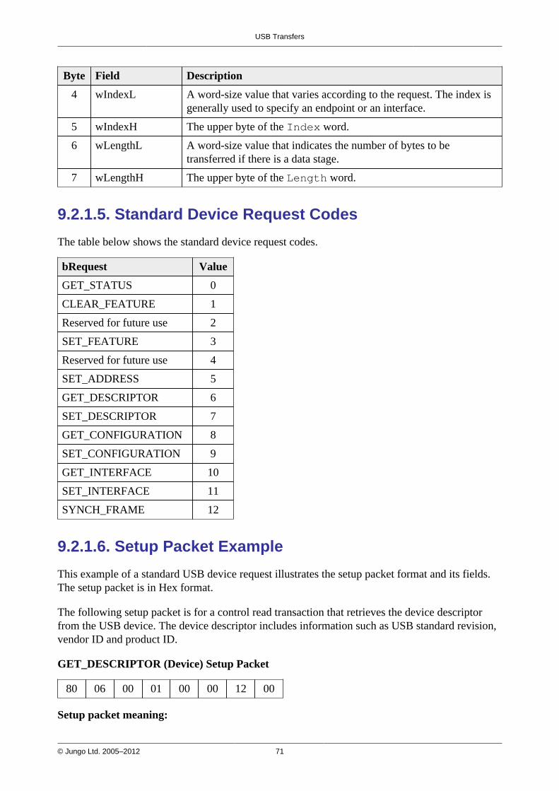
USB Transfers
© Jungo Ltd. 2005–2012 71
Byte Field Description
4 wIndexL A word-size value that varies according to the request. The index isgenerally used to specify an endpoint or an interface.
5 wIndexH The upper byte of the Index word.
6 wLengthL A word-size value that indicates the number of bytes to betransferred if there is a data stage.
7 wLengthH The upper byte of the Length word.
9.2.1.5. Standard Device Request Codes
The table below shows the standard device request codes.
bRequest Value
GET_STATUS 0
CLEAR_FEATURE 1
Reserved for future use 2
SET_FEATURE 3
Reserved for future use 4
SET_ADDRESS 5
GET_DESCRIPTOR 6
SET_DESCRIPTOR 7
GET_CONFIGURATION 8
SET_CONFIGURATION 9
GET_INTERFACE 10
SET_INTERFACE 11
SYNCH_FRAME 12
9.2.1.6. Setup Packet Example
This example of a standard USB device request illustrates the setup packet format and its fields.The setup packet is in Hex format.
The following setup packet is for a control read transaction that retrieves the device descriptorfrom the USB device. The device descriptor includes information such as USB standard revision,vendor ID and product ID.
GET_DESCRIPTOR (Device) Setup Packet
80 06 00 01 00 00 12 00
Setup packet meaning:
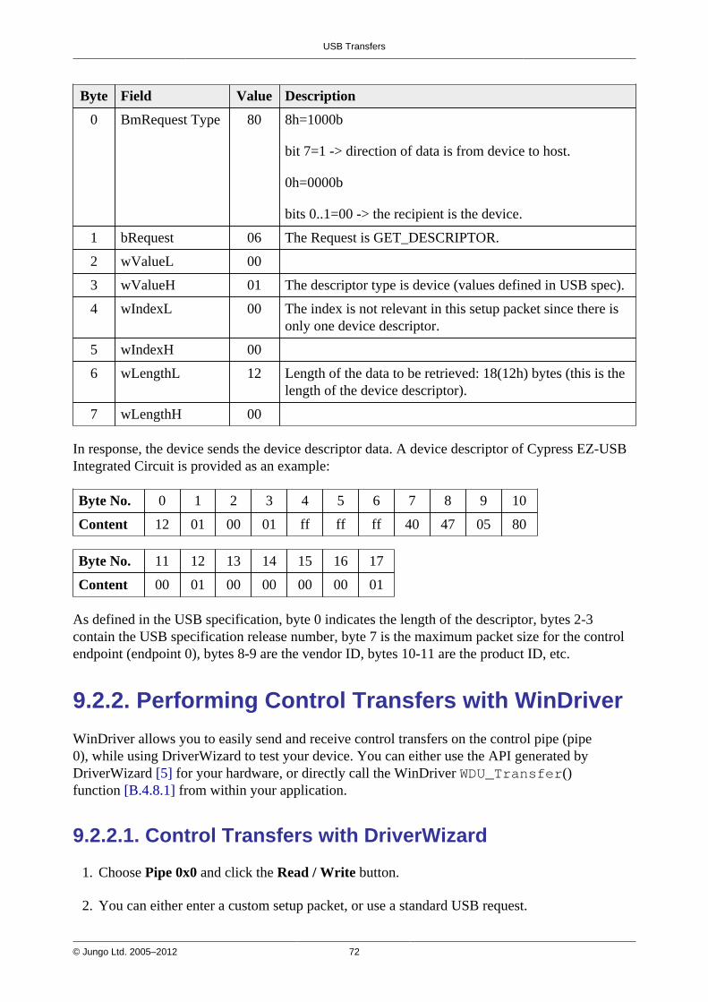
USB Transfers
© Jungo Ltd. 2005–2012 72
Byte Field Value Description
0 BmRequest Type 80 8h=1000b
bit 7=1 -> direction of data is from device to host.
0h=0000b
bits 0..1=00 -> the recipient is the device.
1 bRequest 06 The Request is GET_DESCRIPTOR.
2 wValueL 00
3 wValueH 01 The descriptor type is device (values defined in USB spec).
4 wIndexL 00 The index is not relevant in this setup packet since there isonly one device descriptor.
5 wIndexH 00
6 wLengthL 12 Length of the data to be retrieved: 18(12h) bytes (this is thelength of the device descriptor).
7 wLengthH 00
In response, the device sends the device descriptor data. A device descriptor of Cypress EZ-USBIntegrated Circuit is provided as an example:
Byte No. 0 1 2 3 4 5 6 7 8 9 10
Content 12 01 00 01 ff ff ff 40 47 05 80
Byte No. 11 12 13 14 15 16 17
Content 00 01 00 00 00 00 01
As defined in the USB specification, byte 0 indicates the length of the descriptor, bytes 2-3contain the USB specification release number, byte 7 is the maximum packet size for the controlendpoint (endpoint 0), bytes 8-9 are the vendor ID, bytes 10-11 are the product ID, etc.
9.2.2. Performing Control Transfers with WinDriver
WinDriver allows you to easily send and receive control transfers on the control pipe (pipe0), while using DriverWizard to test your device. You can either use the API generated byDriverWizard [5] for your hardware, or directly call the WinDriver WDU_Transfer()function [B.4.8.1] from within your application.
9.2.2.1. Control Transfers with DriverWizard
1. Choose Pipe 0x0 and click the Read / Write button.
2. You can either enter a custom setup packet, or use a standard USB request.

USB Transfers
© Jungo Ltd. 2005–2012 73
• For a custom request: enter the required setup packet fields. For a write transaction thatincludes a data stage, enter the data in the Write to pipe data (Hex) field. Click ReadFrom Pipe or Write To Pipe according to the required transaction (see Figure 9.3).
Figure 9.3. Custom Request
• For a standard USB request: select a USB request from the requests list, which includesrequests such as GET_DESCRIPTOR CONFIGURATION, GET_DESCRIPTORDEVICE, GET_STATUS DEVICE, etc. (see Figure 9.4). The description of the selectedrequest will be displayed in the Request Description box on the right hand of the dialoguewindow.
Figure 9.4. Request List

USB Transfers
© Jungo Ltd. 2005–2012 74
3. The results of the transfer, such as the data that was read or a relevant error, are displayed inDriver Wizard's Log window.Figure 9.5, below, shows the contents of the Log window after a successfulGET_DESCRIPTOR DEVICE request.
Figure 9.5. USB Request Log
9.2.2.2. Control Transfers with WinDriver API
To perform a read or write transaction on the control pipe, you can either use the API generatedby DriverWizard for your hardware, or directly call the WinDriver WDU_Transfer()function [B.4.8.1] from within your application.
Fill the setup packet in the BYTE SetupPacket[8] array and call these functions to sendsetup packets on the control pipe (pipe 0) and to retrieve control and status data from the device.
• The following sample demonstrates how to fill the SetupPacket[8] variable with aGET_DESCRIPTOR setup packet:
setupPacket[0] = 0x80; /* BmRequstType */ setupPacket[1] = 0x6; /* bRequest [0x6 == GET_DESCRIPTOR] */ setupPacket[2] = 0; /* wValue */ setupPacket[3] = 0x1; /* wValue [Descriptor Type: 0x1 == DEVICE] */ setupPacket[4] = 0; /* wIndex */ setupPacket[5] = 0; /* wIndex */ setupPacket[6] = 0x12; /* wLength [Size for the returned buffer] */ setupPacket[7] = 0; /* wLength */
• The following sample demonstrates how to send a setup packet to the control pipe (a GETinstruction; the device will return the information requested in the pBuffer variable):
WDU_TransferDefaultPipe(hDev, TRUE, 0, pBuffer, dwSize, bytes_transferred, &setupPacket[0], 10000);
• The following sample demonstrates how to send a setup packet to the control pipe (a SETinstruction):
WDU_TransferDefaultPipe(hDev, FALSE, 0, NULL, 0, bytes_transferred, &setupPacket[0], 10000);
For further information regarding WDU_TransferDefaultPipe(), refer to Section B.4.8.3.For further information regarding WDU_Transfer(), refer to Section B.4.8.1.
USB Transfers
© Jungo Ltd. 2005–2012 75
9.3. Functional USB Data Transfers
9.3.1. Functional USB Data Transfers Overview
Functional USB data exchange is used to move data to and from the device. There are threetypes of USB data transfers: Bulk, Interrupt and Isochronous , which are described in detail inSections 3.6.2–3.6.4 of the manual.
Functional USB data transfers can be implemented using two alternative methods: single-blocking transfers and streaming transfers, both supported by WinDriver, as explained in thefollowing sections. The generated DriverWizard USB code [5.2.1] and the generic WinDriver/util/usb_diag.exe utility [1.9.2] (source code located under the WinDriver/samples/usb_diagdirectory) enable the user to select which type of transfer to perform.
9.3.2. Single-Blocking Transfers
In the single-blocking USB data transfer scheme, blocks of data are synchronously transferred(hence — "blocking") between the host and the device, per request from the host (hence —"single" transfers).
9.3.2.1. Performing Single-Blocking Transfers withWinDriver
WinDriver's WDU_Transfer() function, and the WDU_TransferBulk(),WDU_TransferIsoch(), and WDU_TransferInterrupt() convenience functions — alldescribed in Section B.4.8 of the manual — enable you to easily impelment single-blocking USBdata transfers.
You can also perform single-blocking transfers using the DriverWizard utility (which uses theWDU_Transfer() function), as demonstrated in Section 5.2 of the manual.
9.3.3. Streaming Data Transfers
In the streaming USB data transfer scheme, data is continuously streamed between the host andthe device, using internal buffers allocated by the host driver — "streams".
Stream transfers allow for a sequential data flow between the host and the device, and can be usedto reduce single-blocking transfer overhead, which may occur as a result of multiple function callsand context switches between user and kernel modes. This is especially relevant for devices withsmall data buffers, which might, for example, overwrite data before the host is able to read it, dueto a gap in the data flow between the host and device.
USB Transfers
© Jungo Ltd. 2005–2012 76
9.3.3.1. Performing Streaming with WinDriver
WinDriver's WDU_StreamXXX() functions, described in Section B.4.9 of the manual, enableyou to impelment USB streaming data transfers. Note: These functions are currently supported onWindows and Windows CE.
To begin performing stream transfers, call the WDU_StreamOpen() function [B.4.9.1]. Whenthis function is called, WinDriver creates a new stream object for the specified data pipe. You canopen a stream for any pipe except for the control pipe (pipe 0). The stream's data transfer direction— read/write — is derived from the direction of its pipe.WinDriver supports both blocking and non-blocking stream transfers. The open function'sfBlocking parameter indicates which type of transfer to perform (see explanation below).Streams that perform blocking transfers will henceforth be referred to as "blocking streams", andstreams that perform non-blocking transfers will be referred to as "non-blocking streams".The function's dwRxTxTimeout parameter indicates the desired timeout period for transfersbetween the stream and the device.
After opening a stream, call WDU_StreamStart() [B.4.9.2] to begin data transfers between thestream's data buffer and the device.In the case of a read stream, the driver will constantly read data from the device into thestream's buffer, in blocks of a pre-defined size (as set in the dwRxSize parameter of theWDU_StreamOpen() function [B.4.9.1]. In the case of a write stream, the driver will constantlycheck for data in the stream's data buffer and write any data that is found to the device.
To read data from a read stream to the user-mode host application, callWDU_StreamRead() [B.4.9.3].In case of a blocking stream, the read function blocks until the entire amount of data requested bythe application is transferred from the stream to the application, or until the stream's attempt toread data from the device times out.In the case of a non-blocking stream, the function transfers to the application as much of therequested data as possible, subject to the amount of data currently available in the stream's databuffer, and returns immediately.
To write data from the user-mode host application to a write the stream, callWDU_StreamWrite() [B.4.9.4].In case of a blocking stream, the function blocks until the entire data is written to the stream, oruntil the stream's attempt to write data to the device times out.In the case of a non-blocking stream, the function writes as much of the write data as currentlypossible to the stream, and returns immediately.
For both blocking and non-blocking transfers, the read/write function returns the amount of bytesactually transferred between the stream and the calling application within an output parameter —*pdwBytesRead [B.4.9.3] / *pdwBytesWritten [B.4.9.4].
You can flush an active stream at any time by calling the WDU_StreamFlush()function [B.4.9.5], which writes the entire contents of the stream's data buffer to the device (for awrite stream), and blocks until all pending I/O for the stream is handled.You can flush both blocking and non-blocking streams.

USB Transfers
© Jungo Ltd. 2005–2012 77
You can call WDU_StreamGetStatus() [B.4.9.6] for any open stream in order to get thestream's current status information.
To stop the data streaming between an active stream and the device, callWDU_StreamStop() [B.4.9.7]. In the case of a write stream, the function flushes the stream —i.e., writes its contents to the device — before stopping it.An open stream can be stopped and restarted at any time until it is closed.
To close an open stream, call WDU_StreamClose() [B.4.9.8].The function stops the stream, including flushing its data to the device (in the case of a writestream), before closing it.Note: Each call to WDU_StreamOpen() must have a matching call to WDU_StreamClose()later on in the code in order to perform the necessary cleanup.

© Jungo Ltd. 2005–2012 78
Chapter 10Dynamically Loading Your Driver
10.1. Why Do You Need a DynamicallyLoadable Driver?When adding a new driver, you may be required to reboot the system in order for it to load yournew driver into the system. WinDriver is a dynamically loadable driver, which enables yourcustomers to start your application immediately after installing it, without the need for reboot.
To successfully unload your driver, make sure that there are no open handles to theWinDriver service (windrvr6.sys or your renamed driver (refer to Section 12.2), and thatthere are no connected and enabled Plug-and-Play devices that are registered with thisservice.
10.2. Windows Dynamic Driver Loading
10.2.1. Windows Driver TypesWindows drivers can be implemented as either of the following types:
• Windows Driver Model (WDM) drivers: Files with the extension *.sys on Windows 8/7/Vista/Server 2008/Server 2003/XP/2000/Me/98 (e.g., windrvr6.sys).WDM drivers are installed via the installation of an INF file (see below).
• Non-WDM / Legacy drivers: These include drivers for non-Plug-and-Play Windows operatingsystems (Windows NT 4.0) and files with the extension *.vxd on Windows 98/Me.
The WinDriver Windows kernel module — windrvr6.sys — is a fully WDM driver, which canbe installed using the wdreg utility, as explained in the following sections.
10.2.2. The wdreg UtilityWinDriver provides a utility for dynamically loading and unloading your driver, which replacesthe slower manual process using Windows' Device Manager (which can still be used for thedevice INF). This utility is provided in two forms: wdreg and wdreg_gui. Both versions can befound in the WinDriver\util directory, can be run from the command line, and provide the samefunctionality. The difference is that wdreg_gui displays installation messages graphically, whilewdreg displays them in console mode.
Dynamically Loading Your Driver
© Jungo Ltd. 2005–2012 79
This section describes the use of wdreg/ wdreg_gui on Windows operating systems.
1. wdreg is dependent on the Driver Install Frameworks API (DIFxAPI) DLL —difxapi.dll, unless when run with the -compat option (described below). difxapi.dllis provided under the WinDriver\util directory.
2. The explanations and examples below refer to wdreg, but any references to wdreg canbe replaced with wdreg_gui.
10.2.2.1. Overview
This section explains how to use the wdreg utility to install the WDM windrvr6.sys driver, or toinstall INF files that register USB devices to work with this driver, on Windows.
You can rename the windrvr6.sys kernel module and modify your device INF file toregister with your renamed driver, as explained in Section 12.2.1. To install your modifiedINF files using wdreg, simply replace any references to windrvr6 below with the name ofyour new driver.
Usage: The wdreg utility can be used in two ways as demonstrated below:
1. wdreg -inf <filename> [-silent] [-log <logfile>][install | preinstall | uninstall | enable | disable]
2. wdreg -rescan <enumerator> [-silent] [-log <logfile>]
• OPTIONSwdreg supports several basic OPTIONS from which you can choose one, some, or none:
• -inf — The path of the INF file to be dynamically installed.
• -rescan <enumerator> — Rescan enumerator (ROOT, USB, etc.) for hardware changes.Only one enumerator can be specified.
• -silent — Suppress display of all messages (optional).
• -log <logfile> — Log all messages to the specified file (optional).
• -compat — Use the traditional SetupDi API instead of the newer Driver Install FrameworksAPI (DIFxAPI).
• ACTIONSwdreg supports several basic ACTIONS:
• install — Installs the INF file, copies the relevant files to their target locations, anddynamically loads the driver specified in the INF file name by replacing the older version (ifneeded).
• preinstall Pre-installs the INF file for a non-present device.
Dynamically Loading Your Driver
© Jungo Ltd. 2005–2012 80
• uninstall — Removes your driver from the registry so that it will not load on next boot (seenote below).
• enable — Enables your driver.
• disable — Disables your driver, i.e., dynamically unloads it, but the driver will reload aftersystem boot (see note below).
To successfully disable/uninstall your driver, make sure that there are no open handles tothe WinDriver service (windrvr6.sys or your renamed driver (refer to Section 12.2), andthat there are no connected and enabled Plug-and-Play devices that are registered with thisservice.
10.2.3. Dynamically Loading/Unloadingwindrvr6.sys INF Files
When using WinDriver, you develop a user-mode application that controls and accesses yourhardware by using the generic windrvr6.sys driver (WinDriver's kernel module). Therefore, youmight want to dynamically load and unload the driver windrvr6.sys — which you can do usingwdreg.In addition, in WDM-compatible operating systems, you also need to dynamically load INF filesfor your Plug-and-Play devices. wdreg enables you to do so automatically on Windows.This section includes wdreg usage examples, which are based on the detailed description ofwdreg contained in the previous section.
• To load windrvr6.inf and start the windrvr6.sys service —wdreg -inf <path to windrvr6.inf> install
• To load an INF file named device.inf, located in the c:\tmp directory —wdreg -inf c:\tmp\device.inf install
You can replace the install option in the example above with preinstall to pre-installthe device INF file for a device that is not currently connected to the PC.
If the installation fails with an ERROR_FILE_NOT_FOUND error, inspect the Windowsregistry to see if the RunOnce key exists in HKEY_LOCAL_MACHINE\SOFTWARE\Microsoft\Windows\CurrentVersion. This registry key is required by WindowsPlug-and-Play in order to properly install drivers using INF files. If the RunOnce key ismissing, create it; then try installing the INF file again.
To unload the driver/INF file, use the same commands, but simply replace install in theexamples above with uninstall.

Dynamically Loading Your Driver
© Jungo Ltd. 2005–2012 81
10.3. Linux Dynamic Driver Loading
The following commands must be executed with root privileges.
• To dynamically load WinDriver, run the following command:# <path to wdreg> windrvr6
• To dynamically unload WinDriver, run the following command:# /sbin/modprobe -r windrvr6.
wdreg is provided in the WinDriver/util directory.
To automatically load WinDriver on each boot, add the following line to the target's Linuxboot file (for example, /etc/rc.local):<path to wdreg> windrvr6
10.4. Windows CE Dynamic Driver LoadingThe WinDriver\redist\Windows_Mobile_5_ARMV4I\wdreg.exe utility can be used for loadingthe WinDriver kernel module (windrvr6.dll) on a Windows CE platform.
On many versions of Windows CE, the operating system's security scheme prevents theloading of unsigned drivers at boot time, therefore the WinDriver kernel module has to bereloaded after boot. To load WinDriver on the target Windows CE platform every time theOS is started, copy the wdreg.exe utility to the Windows\StartUp directory on the targetPC.
The source code of the Windows CE wdreg.exe utility is available under theWinDriver\samples\wince_install\wdreg directory on the development PC.
© Jungo Ltd. 2005–2012 82
Chapter 11Distributing Your Driver
Read this chapter in the final stages of driver development. It will guide you in preparingyour driver for distribution.
11.1. Getting a Valid License for WinDriverTo purchase a WinDriver license, complete the WinDriver/docs/order.pdf order form and fax oremail it to Jungo. Complete details are included on the order form. Alternatively, you can orderWinDriver online. For more details, visit our web site: http://www.jungo.com.
In order to install the registered version of WinDriver and to activate driver code that youhave developed during the evaluation period on the development machine, please follow theinstallation instructions found in Section 4.2 above.
11.2. Windows Driver Distribution• All references to wdreg in this section can be replaced with wdreg_gui, which offers
the same functionality as wdreg but displays GUI messages instead of console-modemessages.
• If you have renamed the WinDriver kernel module (windrvr6.sys), as explained inSection 12.2, replace the relevant windrvr6 references with the name of your driver,and replace references to the WinDriver\redist directory with the path to the directorythat contains your modified installation files. For example, when using the generatedDriverWizard renamed driver files for your driver project, as explained in Section 12.2.1,you can replace references to the WinDriver\redist directory with references to thegenerated xxx_installation\redist directory (where xxx is the name of your generateddriver project). Note also the option to simplify the installation using the generatedDriverWizard xxx_install.bat script and the copies of the WinDriver\util installationfiles in the generated xxx_installation\redist directory, as explained in Section 12.2.1.
• If you have created new INF and/or catalog files for your driver, replace the references tothe original WinDriver INF files and/or to the wd1110.cat catalog file with the names ofyour new files (see the file renaming information in Sections 12.2.1 and 12.3.2).
Distributing the driver you created is a multi-step process. First, create a distribution package thatincludes all the files required for the installation of the driver on the target computer. Second,install the driver on the target machine. This involves installing windrvr6.sys and windrvr6.inf,and installing the specific INF file for your device.
Distributing Your Driver
© Jungo Ltd. 2005–2012 83
Finally, you need to install and execute the hardware control application that you developed withWinDriver. These steps can be performed using wdreg utility.
11.2.1. Preparing the Distribution Package
Prepare a distribution package that includes the following files.
If you wish to distribute drivers for both 32-bit and 64-bit target platforms, you mustprepare separate distribution packages for each platform. The required files for eachpackage are provided in the WinDriver installation directory for the respective platform.
• Your hardware control application/DLL.
• windrvr6.sys.Get this file from the WinDriver\redist directory of the WinDriver package.
• windrvr6.inf.Get this file from the WinDriver\redist directory of the WinDriver package.
• wd1110.cat.Get this file from the WinDriver\redist directory of the WinDriver package.
• wdapi1110.dll (for distribution of 32-bit binaries to 32-bit target platforms or for distributionof 64-bit binaries to 64-bit platforms) or wdapi1110_32.dll (for distribution of 32-bit binariesto 64-bit platforms [A.2].Get this file from the WinDriver\redist directory of the WinDriver package.
• difxapi.dll (required by the wdreg.exe utility [10.2.2]).Get this file from the WinDriver\util directory of the WinDriver package.
• An INF file for your device.You can generate this file with DriverWizard, as explained in Section 5.2.
11.2.2. Installing Your Driver on the TargetComputer
Driver installation on Windows requires administrator privileges.
Follow the instructions below in the order specified to properly install your driver on the targetcomputer:
Distributing Your Driver
© Jungo Ltd. 2005–2012 84
• Preliminary Steps:To successfully install your driver, make sure that there are no open handles to the WinDriverservice (windrvr6.sys or your renamed driver (refer to Section 12.2), and that there are noconnected and enabled Plug-and-Play devices that are registered with this service. This isrelevant, for example, when upgrading the version of the driver (for WinDriver v6.0.0 andabove; earlier versions used a different module name). If the service is being used, attemptsto install the new driver using wdreg will fail. You can disable or uninstall connected devicesfrom the Device Manager (Properties | Disable/Uninstall) or using wdreg, or otherwisephysically disconnect the device(s) from the PC.
• Install WinDriver's kernel module:
1. Copy windrvr6.sys, windrvr6.inf, and wd1110.cat to the same directory.
wd1110.cat contains the driver's Authenticode digital signature. To maintain thesignature's validity this file must be found in the same installation directory as thewindrvr6.inf file. If you select to distribute the catalog and INF files in differentdirectories, or make any changes to these files or to any other files referred to by thecatalog file (such as windrvr6.sys), you will need to do either of the following:
• Create a new catalog file and re-sign the driver using this file.
• Comment-out or remove the following line in the windrvr6.inf file:CatalogFile=wd1110.catand do not include the catalog file in your driver distribution. However, note thatthis option invalidates the driver's digital signature.
For more information regarding driver digital signing and certification and thesigning of your WinDriver-based driver, refer to Section 12.3 of the manual.
2. Use the utility wdreg to install WinDriver's kernel module on the target computer:wdreg -inf <path to windrvr6.inf> install
For example, if windrvr6.inf and windrvr6.sys are in the d:\MyDevice directory on thetarget computer, the command should be:wdreg -inf d:\MyDevice\windrvr6.inf install
You can find the executable of wdreg in the WinDriver package under the WinDriver\utildirectory. For a general description of this utility and its usage, please refer to Chapter 10.
• wdreg is dependent on the difxapi.dll DLL.
• wdreg is an interactive utility. If it fails, it will display a message instructing theuser how to overcome the problem. In some cases the user may be asked to rebootthe computer.

Distributing Your Driver
© Jungo Ltd. 2005–2012 85
When distributing your driver, you should attempt to ensure that the installationdoes not overwrite a newer version of windrvr6.sys with an older version ofthe file in Windows drivers directory (%windir%\system32\drivers) — forexample, by configuring your installation program (if you are using one) oryour INF file so that the installer automatically compares the time stamp onthese two files and does not overwrite a newer version with an older one. Theprovided windrvr6.inf file uses the COPYFLG_NO_VERSION_DIALOG directive,which is designed to avoid overwriting a file in the destination directory with thesource file if the existing file is newer than the source file. There is also a similarCOPYFLG_OVERWRITE_OLDER_ONLY INF directive that is designed to ensurethat the source file is copied to the destination directory only if the destinationfile is superseded by a newer version. Note, however, that both of these INFdirectives are irrelevant to digitally signed drivers. As explained in the MicrosoftINF CopyFiles Directive documentation — http://msdn.microsoft.com/en-us/library/ff546346%28v=vs.85%29.aspx — if a driver package is digitally signed, Windowsinstalls the package as a whole and does not selectively omit files in the packagebased on other versions already present on the computer. The windrvr6.sys driverprovided by Jungo is digitally signed (refer to Section 12.3 for more information).
• Install the INF file for your device (registering your Plug-and-Play device withwindrvr6.sys):
Run the utility wdreg with the install command to automatically install the INF file andupdate Windows Device Manager:wdreg -inf <path to your INF file> install
You can also use the wdreg utility's preinstall command to pre-install an INF file for adevice that is not currently connected to the PC:wdreg -inf <path to your INF file> preinstall
If the installation fails with an ERROR_FILE_NOT_FOUND error, inspect the Windowsregistry to see if the RunOnce key exists in HKEY_LOCAL_MACHINE\SOFTWARE\Microsoft\Windows\CurrentVersion. This registry key is required byWindows Plug-and-Play in order to properly install drivers using INF files. If theRunOnce key is missing, create it; then try installing the INF file again.
• Install wdapi1110.dll:If your hardware control application/DLL uses wdapi1110.dll (as is the case for thesample and generated DriverWizard WinDriver projects), copy this DLL to the target's%windir%\system32 directory.If you are distributing a 32-bit application/DLL to a target 64-bit platform [A.2], renamewdapi1110_32.dll in your distribution package to wdapi1110.dll, and copy the renamed file tothe target's %windir%\sysWOW64 directory.

Distributing Your Driver
© Jungo Ltd. 2005–2012 86
If you attempt to write a 32-bit installation program that installs a 64-bit program, andtherefore copies the 64-bit wdapi1110.dll DLL to the %windir%\system32 directory,you may find that the file is actually copied to the 32-bit %windir%\sysWOW64directory. The reason for this is that Windows x64 platforms translate references to64-bit directories from 32-bit commands into references to 32-bit directories. You canavoid the problem by using 64-bit commands to perform the necessary installation stepsfrom your 32-bit installation program. The system64.exe program, provided in theWinDriver\redist directory of the Windows x64 WinDriver distributions, enables you todo this.
• Install your hardware control application/DLL: Copy your hardware control application/DLL to the target and run it!
11.3. Windows CE Driver Distribution
11.3.1. Distribution to New Windows CE Platforms
The following instructions apply to platform developers who build Windows CE kernelimages using Windows CE Platform Builder or using MS Visual Studio 2005/2008 with theappropriate Windows CE plugin. The instructions use the notation 'Windows CE IDE' torefer to either of these platforms.
To distribute the driver you developed with WinDriver to a new target Windows CE platform,follow these steps:
1. Modify the project registry file to add an entry for your target device:
• If you select to use the WinDriver component (refer to Step 2), modifyWinDriver\samples\wince_install\<TARGET_CPU>\WinDriver.reg (e.g.,WinDriver\samples\wince_install\ARMV4I\WinDriver.reg).
• Otherwise, modify WinDriver\samples\wince_install\project_wd.reg.
2. For Windows CE 4.x–5.x only, you can simplify the driver integration into your WindowsCE platform by following the procedure described in this step, before the Sysgen platformcompilation stage.
Note:
• Developers who use Windows CE 6.x and higher should skip to the next step (Step 3).
• This procedure provides a convenient method for integrating WinDriver into yourWindows CE platform. If you select not to use this method, you will need to perform themanual integration steps described in Step 4 below, after the Sysgen stage.

Distributing Your Driver
© Jungo Ltd. 2005–2012 87
• The procedure described in this step also adds the WinDriver kernel module(windrvr6.dll) to your OS image. This is a necessary step if you want the WinDriver CEkernel file (windrvr6.dll) to be a permanent part of the Windows CE image (NK.BIN),which is the case if you select to transfer the file to your target platform using a boot disk.However, if you prefer to have the file windrvr6.dll loaded on demand via the CESH/PPSH services, you need to perform the manual integration method described in Step 4instead of performing the procedure described in the present step.
a. Run the Windows CE IDE and open your platform.
b. From the File menu select Manage Catalog Items...., click theImport... button, and select the WinDriver.cec file from the relevantWinDriver\samples\wince_install\<TARGET_CPU> directory (e.g.,WinDriver\samples\wince_install\ARMV4I). This will add a WinDriver component tothe Platform Builder Catalog.
c. In the Catalog view, right-click the mouse on the WinDriver Component node in theThird Party tree, and select Add to OS design.
3. Compile your Windows CE platform (Sysgen stage).
4. If you did not perform the procedure described in Step 2 above, perform the following stepsafter the Sysgen stage in order to manually integrate the driver into your platform.Note: If you followed the procedure described in Step 2, skip this step and go directly toStep 5.
a. Run the Windows CE IDE and open your platform.
b. Select Open Release Directory from the Build menu.
c. Copy the WinDriver CE kernel file —WinDriver\redist\<TARGET_CPU>\windrvr6.dll — to the%_FLATRELEASEDIR% subdirectory on the target development platform (should bethe current directory in the new command window).
d. Append the contents of WinDriver\samples\wince_install\project_wd.reg to the%_FLATRELEASEDIR%\project.reg registry file.
e. Copy the contents of the WinDriver\samples\wince_install\project_wd.bibfile to the FILES section of the binary image builder file —%_FLATRELEASEDIR%\project.bib. Then uncomment the line that matches thetarget platform (see the "TODO" comments in the copied text).

Distributing Your Driver
© Jungo Ltd. 2005–2012 88
This step is only necessary if you want the WinDriver CE kernel file(windrvr6.dll) to be a permanent part of the Windows CE image (NK.BIN),which is the case if you select to transfer the file to your target platform usinga boot disk. If you prefer to have the file windrvr6.dll loaded on demand viathe CESH/PPSH services, you do not need to perform this step until you build apermanent kernel.
5. Select Make Run-Time Image from the Build menu, and name the new image NK.BIN.
6. Download your new kernel to the target platform and initialize it either by selectingAttach Device from the Target menu, or by using a boot disk. For Windows CE 4.x, themenu is called Download/Initialize rather than Attach Device.
7. Restart your target CE platform. The WinDriver CE kernel will automatically load.
8. Install your hardware control application/DLL on the target.If your hardware control application/DLL uses wdapi1110.dll (as is the case for thesample and generated DriverWizard WinDriver projects), also copy this DLL from theWinDriver\redist\WINCE\<TARGET_CPU> directory on the Windows host developmentPC to the target's Windows directory.
11.3.2. Distribution to Windows CE Computers
Unless otherwise specified, 'Windows CE' references in this section include all supportedWindows CE platforms, including Windows Mobile.
1. Copy WinDriver's kernel module — windrvr6.dll — from theWinDriver\redist\WINCE\<TARGET_CPU> directory on the Windows host developmentPC to the Windows directory on your target Windows CE platform.
2. Add WinDriver to the list of device drivers Windows CE loads on boot:
• Modify the registry according to the entries documented in the fileWinDriver\samples\wince_install\project_wd.reg. This can be done using the WindowsCE Pocket Registry Editor on the hand-held CE computer, or by using the Remote CERegistry Editor Tool supplied with MS eMbedded Visual C++ or MS Visual Studio2005/2008. Note that in order to use the Remote CE Registry Editor tool you will need tohave Windows CE Services installed on your Windows host platform.
• On many versions of Windows CE, the operating system's security scheme prevents theloading of unsigned drivers at boot time, therefore the WinDriver kernel module has tobe reloaded after boot. To load WinDriver on the target Windows CE platform every timethe OS is started, copy the WinDriver\redist\Windows_Mobile_5_ARMV4I\wdreg.exeutility to the Windows\StartUp directory on the target PC.
Distributing Your Driver
© Jungo Ltd. 2005–2012 89
3. Restart your target CE computer. The WinDriver CE kernel will automatically load. You willhave to do a warm reset rather than just suspend/resume (use the reset or power button onyour target CE computer).
4. Install your hardware control application/DLL on the target.If your hardware control application/DLL uses wdapi1110.dll (as is the case for thesample and generated DriverWizard WinDriver projects), also copy this DLL from theWinDriver\redist\WINCE\<TARGET_CPU> directory on the development PC to thetarget's Windows directory.
11.4. Linux Driver DistributionTo distribute your driver, prepare a distribution package containing the required files — asoutlined in Section 11.4.1 — and then build and install the required driver components on thetarget — as outlined in Sections 11.4.2–11.4.3.
• If you have renamed the WinDriver driver modules [12.2], replace references towindrvr6 in the following instructions with the name of your renamed driver module.
• It is recommended that you supply an installation shell script to automate the build andinstallation processes on the target.
11.4.1. Preparing the Distribution Package
Prepare a distribution package containing the required files, as described in this section.
• If you wish to distribute drivers for both 32-bit and 64-bit target platforms, you mustprepare separate distribution packages for each platform. The required files for eachpackage are provided in the WinDriver installation directory for the respective platform.
• In the following instructions, <source_dir> represents the source directory from whichto copy the distribution files. The default source directory is your WinDriver installationdirectory. However, if you have renamed the WinDriver driver modules [12.2], thesource directory is a directory containing modified files for compiling and installingthe renamed drivers; when using DriverWizard to generate the driver code, the sourcedirectory for the renamed driver is the generated xxx_installation directory, where xxx isthe name of your generated driver project (see Section 12.2.2, Step 1).
11.4.1.1. Kernel Module Components
WinDriver uses two kernel modules: the main WinDriver driver module, which implements theWinDriver API — windrvr6.o/.ko — and a driver module that implements the USB functionality— windrvr6_usb.o/.ko.
Distributing Your Driver
© Jungo Ltd. 2005–2012 90
Your kernel driver modules cannot be distributed as-is; they must be recompiled on eachtarget machine, to match the kernel version on the target. This is due to the followingreason: The Linux kernel is continuously under development, and kernel data structuresare subject to frequent changes. To support such a dynamic development environment,and still have kernel stability, the Linux kernel developers decided that kernel modulesmust be compiled with header files identical to those with which the kernel itself wascompiled. They enforce this by including a version number in the kernel header files, whichis checked against the version number encoded into the kernel. This forces Linux driverdevelopers to support recompilation of their driver with the target system's kernel version.
Following is a list of the components you need to distribute to enable compilation of your kerneldriver modules on the target machine.
It is recommended that you copy the files to subdirectories in the distribution directorythat match the source subdirectories, such as redist and include, except where otherwisespecified. If you select not do so, you will need to modify the file paths in the configurationscripts and related makefile templates, to match the location of the files in your distributiondirectory.
• From the <source_dir>/include directory, copy windrvr.h, wd_ver.h, and windrvr_usb.h —header files required for building the kernel modules on the target.
• From the <WinDriver installation directory>/util directory (or from the generatedDriverWizard xxx_installation/redist directory), copy wdreg — a script for loading theWinDriver kernel driver modules (see Section 10.3) — to the redist distribution directory.
• From the <source_dir>/redist directory, unless where otherwise specified, copy the followingfiles:
setup_inst_dir — a script for installing the WinDriver driver modules, using wdreg (seeabove).
linux_wrappers.c/.h — wrapper library source code files that bind the kernel module to theLinux kernel.
linux_common.h and wdusb_interface.h — header files required for building the kernelmodules on the target.
wdusb_linux.c — source file used by WinDriver to utilize the USB stack.
The compiled object code for building the WinDriver kernel driver modules —
windrvr_gcc_v3.a — for GCC v3.x.x compilation
windrvr_gcc_v3_regparm.a — for GCC v3.x.x compilation with the regparm flag
windrvr_gcc_v2.a — for GCC v2.x.x compilation; note that this file is not found in the64-bit WinDriver installations, because 64-bit Linux architectures don't use GCC v2.
Distributing Your Driver
© Jungo Ltd. 2005–2012 91
Configuration scripts and makefile templates for creating makefiles for building andinstalling the WinDriver kernel driver modules.
Files that include .kbuild in their names use kbuild for the driver compilation.
configure — a configuration script that uses the makefile.in template to create a makefilefor building and installing the WinDriver driver modules, and executes the configure.wdand configure.usb scripts (see below).
configure.wd — a configuration script that uses the makefile.wd[.kbuild].in template tocreate a makefile.wd[.kbuild] makefile for building the windrvr6.o/.ko driver module.
configure.usb — a configuration script that uses the makefile.usb[.kbuild].in templateto create a makefile.usb[.kbuild] makefile for building the windrvr6_usb.o/.ko drivermodule.
makefile.in — a template for the main makefile for building and installing the WinDriverkernel driver modules, using makefile.wd[.kbuild] and makefile.usb[.kbuild].
makefile.wd.in and makefile.wd.kdbuild.in — templates for creatingmakefile.wd[.kbuild] makefiles for building and installing the windrvr6.o/.ko drivermodule.
makefile.usb.in and makefile.usb.kdbuild.in — templates for creatingmakefile.usb[.kbuild] makefiles for building and installing the windrvr6_usb.o/.kodriver module.
11.4.1.2. User-Mode Hardware Control Application orShared Object
Copy the user-mode hardware control application or shared object that you created withWinDriver, to the distribution package.
If your hardware control application/shared object uses libwdapi1110.so — as is the casefor the WinDriver samples and generated DriverWizard projects — copy this file from the<source_dir>/lib directory to your distribution package.If you are distributing a 32-bit application/shared object to a target 64-bit platform [A.2] — copylibwdapi1110_32.so from the WinDriver/lib directory to your distribution package, and renamethe copy to libwdapi1110.so.
Since your hardware control application/shared object does not have to be matched against theLinux kernel version number, you may distribute it as a binary object (to protect your code fromunauthorized copying). If you select to distribute your driver's source code, note that under thelicense agreement with Jungo you may not distribute the source code of the libwdapi1110.soshared object, or the WinDriver license string used in your code.
Distributing Your Driver
© Jungo Ltd. 2005–2012 92
11.4.2. Building and Installing the WinDriver DriverModules on the Target
From the distribution package subdirectory containing the configure script and related build andinstallation files — normally the redist subdirectory [11.4.2] — perform the following steps tobuild and install the driver modules on the target:
1. Generate the required makefiles:$ ./configure
• The configuration script creates a makefile based on the running kernel. Youmay select to use another installed kernel source, by executing the script with the--with-kernel-source=<path> option, where <path> is the full path tothe kernel source directory — e.g., /usr/src/linux.
• If the Linux kernel version is 2.6.26 or higher, the configuration script generatesmakefiles that use kbuild to compile the kernel modules. You can force the use ofkbuild on earlier versions of Linux, by executing the configuration script with the--enable-kbuild flag.
For a full list of the configuration script options, use the --help option:./configure --help
2. Build the WinDriver driver modules:$ make
This will create a LINUX.<kernel version>.<CPU> directory, containing the newlycompiled driver modules — windrvr6.o/.ko and windrvr6_usb.o/.ko.
3. Install the windrvr6.o/.ko and windrvr6_usb.o/.ko driver modules.
The following command must be executed with root privileges.
# make install
The installation is performed using the setup_inst_dir script, which copies the drivermodules to the target's loadable kernel modules directory, and uses the wdreg script [10.3] toload the driver modules.
4. Change the user and group IDs and give read/write permissions to the device file/dev/windrvr6, depending on how you wish to allow users to access hardwarethrough the device. Due to security reasons, by default the device file is createdwith permissions only for the root user. Change the permissions by modifying your/etc/udev/permissions.d/50-udev.permissions file. For example, add the following line toprovide read and write permissions:windrvr6:root:root:0666
Distributing Your Driver
© Jungo Ltd. 2005–2012 93
Use the wdreg script to dynamically load the WinDriver driver modules on the targetafter each boot [10.3]. To automate this, copy wdreg to the target machine, and add thefollowing line to the target's Linux boot file (for example, /etc/rc.local):<path to wdreg> windrvr6
11.4.3. Intsalling the User-Mode Hardware ControlApplication or Shared Object
If your user-mode hardware control application or shared object uses libwdapi1110.so [11.4.1.2],copy libwdapi1110.so from the distribution package to the target's library directory:
• /usr/lib — when distributing a 32-bit application/shared object to a 32-bit or 64-bit target
• /usr/lib64 — when distributing a 64-bit application/shared object to a 64-bit target
If you decided to distribute the source code of the application/shared object [11.4.1.2], copy thesource code to the target as well.
Remember that you may not distribute the source code of the libwdapi1110.so sharedobject or your WinDriver license string as part of the source code distribution [11.4.1.2].
© Jungo Ltd. 2005–2012 94
Chapter 12Driver Installation — AdvancedIssues
12.1. Windows INF FilesDevice information (INF) files are text files that provide information used by the Plug-and-Playmechanism on Windows 8 / 7 / Vista / Server 2008 / Server 2003 / XP / 2000 / Me / 98 to installsoftware that supports a given hardware device. INF files are required for hardware that identifiesitself, such as USB and PCI. An INF file includes all necessary information about a device andthe files to be installed. When hardware manufacturers introduce new products, they must createINF files to explicitly define the resources and files required for each class of device.
In some cases, the INF file for your specific device is supplied by the operating system. Inother cases, you will need to create an INF file for your device. WinDriver's DriverWizard cangenerate a specific INF file for your device. The INF file is used to notify the operating systemthat WinDriver now handles the selected device.
For USB devices, you will not be able to access the device with WinDriver (either fromDriverWizard or from the code) without first registering the device to work with windrvr6.sys.This is done by installing an INF file for the device. DriverWizard will offer to automaticallygenerate the INF file for your device.
You can use DriverWizard to generate the INF file on the development machine — as explainedin Section 5.2 of the manual — and then install the INF file on any machine to which youdistribute the driver, as explained in the following sections.
12.1.1. Why Should I Create an INF File?
• To bind the WinDriver kernel module to a specific USB device.
• To override the existing driver (if any).
• To enable WinDriver applications and DriverWizard to access a USB device.
Driver Installation — Advanced Issues
© Jungo Ltd. 2005–2012 95
12.1.2. How Do I Install an INF File When No DriverExists?
You must have administrative privileges in order to install an INF file.
You can use the wdreg utility with the install command to automatically install the INF file:wdreg -inf <path to the INF file> install(For more information, refer to Section 10.2.2 of the manual.)
On the development PC, you can have the INF file automatically installed when selecting togenerate the INF file with DriverWizard, by checking the Automatically Install the INF fileoption in the DriverWizard's INF generation window (refer to Section 5.2).
It is also possible to install the INF file manually, using either of the following methods:
• Windows Found New Hardware Wizard: This wizard is activated when the device is pluggedin or, if the device was already connected, when scanning for hardware changes from theDevice Manager.
• Windows Add/Remove Hardware Wizard: Right-click the mouse on My Computer, selectProperties, choose the Hardware tab and click on Hardware Wizard....
• Windows Upgrade Device Driver Wizard: Locate the device in the Device Manager deviceslist and select the Update Driver... option from the right-click mouse menu or from the DeviceManager's Action menu.
In all the manual installation methods above you will need to point Windows to the location of therelevant INF file during the installation.We recommend using the wdreg utility to install the INF file automatically, instead of installing itmanually.
If the installation fails with an ERROR_FILE_NOT_FOUND error, inspect the Windowsregistry to see if the RunOnce key exists in HKEY_LOCAL_MACHINE\SOFTWARE\Microsoft\Windows\CurrentVersion. This registry key is required by WindowsPlug-and-Play in order to properly install drivers using INF files. If the RunOnce key ismissing, create it; then try installing the INF file again.
12.1.3. How Do I Replace an Existing Driver Usingthe INF File?
You must have administrative privileges in order to replace a driver.
1. Install your INF file.
Driver Installation — Advanced Issues
© Jungo Ltd. 2005–2012 96
You can use the wdreg utility with the install command to automatically install the INFfile:wdreg -inf <path to INF file> install(For more information, refer to Section 10.2.2 of the manual.)
On the development PC, you can have the INF file automatically installed when selecting togenerate the INF file with DriverWizard, by checking the Automatically Install the INF fileoption in the DriverWizard's INF generation window (refer to Section 5.2).
It is also possible to install the INF file manually, using either of the following methods:
• Windows Found New Hardware Wizard: This wizard is activated when the device isplugged in or, if the device was already connected, when scanning for hardware changesfrom the Device Manager.
• Windows Add/Remove Hardware Wizard: Right-click on My Computer, selectProperties, choose the Hardware tab and click on Hardware Wizard....
• Windows Upgrade Device Driver Wizard: Locate the device in the Device Managerdevices list and select the Update Driver... option from the right-click mouse menu orfrom the Device Manager's Action menu.
In the manual installation methods above you will need to point Windows to the location ofthe relevant INF file during the installation. If the installation wizard offers to install an INFfile other than the one you have generated, select Install one of the other drivers and chooseyour specific INF file from the list.
We recommend using the wdreg utility to install the INF file automatically, instead ofinstalling it manually.
If the installation fails with an ERROR_FILE_NOT_FOUND error, inspect the Windowsregistry to see if the RunOnce key exists in HKEY_LOCAL_MACHINE\SOFTWARE\Microsoft\Windows\CurrentVersion. This registry key is required by WindowsPlug-and-Play in order to properly install drivers using INF files. If the RunOnce key ismissing, create it; then try installing the INF file again.
12.2. Renaming the WinDriver Kernel DriverThe WinDriver APIs are implemented within the WinDriver kernel driver module(windrvr6.sys/.dll/.o/.ko — depending on the OS), which provides the main driver functionalityand enables you to code your specific driver logic from the user mode [1.5].
On Windows and Linux you can change the name of the WinDriver kernel module to yourpreferred driver name, and then distribute the renamed driver instead of default kernel module— windrvr6.sys/.o/.ko. The following sections explain how to rename the driver for each of thesupported operating systems.

Driver Installation — Advanced Issues
© Jungo Ltd. 2005–2012 97
A renamed WinDriver kernel driver can be installed on the same machine as the originalkernel module.You can also install multiple renamed WinDriver drivers on the same machine,simultaneously.
Try to give your driver a unique name in order to avoid a potenial conflict with other driverson the target machine on which your driver will be installed.
12.2.1. Windows Driver RenamingDriverWizard automates most of the work of renaming the Windows WinDriver kernel driver —windrvr6.sys.
• When renaming the driver, the CPU architecture (32-/64-bit) of the developmentplatform and its WinDriver installation, should match the target platform.
• Renaming the signed windrvr6.sys driver nullifies its signature. In such cases youcan select either to sign your new driver, or to distribute an unsigned driver. For moreinformation on driver signing and certification, refer to Section 12.3. For guidelines forsigning and certifying your renamed driver, refer to Section 12.3.2.
References to xxx in this section should be replaced with the name of your generatedDriverWizard driver project.
To rename your Windows WinDriver kernel driver, follow these steps:
1. Use the DriverWizard utility to generate driver code for your hardware on Windows (referto Section 5.2, Step 7), using your preferred driver name (xxx) as the name of the generateddriver project. The generated project directory (xxx) will include an xxx_installationdirectory with the following files and directories:
• redist directory:
• xxx.sys — Your new driver, which is actually a renamed copy of the windrvr6.sysdriver. Note: The properties of the generated driver file (such as the file's version,company name, etc.) are identical to the properties of the original windrvr6.sys driver.You can rebuild the driver with new properties using the files from the generatedxxx_installation sys directory, as explained below.
• xxx_driver.inf — A modified version of the windrvr6.inf file, which will be used toinstall your new xxx.sys driver.You can make additional modifications to this file, if you wish — namely, changing thestring definitions and/or comments in the file.
• xxx_device.inf — A modified version of the standard generated DriverWizard INF filefor your device, which registers your device with your driver (xxx.sys).You can make additional modifications to this file, if you wish, such as changing themanufacturer or driver provider strings.

Driver Installation — Advanced Issues
© Jungo Ltd. 2005–2012 98
• wdapi1110.dll — A copy of the WinDriver API DLL. The DLL is copied here inorder to simplify the driver distribution, allowing you to use the generated xxx\redistdirectory as the main installation directory for your driver, instead of the originalWinDriver\redist directory.
• wdreg.exe, wdreg_gui.exe, and difxapi.dll — Copies of the CUI and GUI versions ofthe wdreg WinDriver driver installation utility, and the Driver Install Frameworks API(DIFxAPI) DLL required by this utility [10.2.2], (respectively). These files are copiedfrom the WinDriver\util directory, to simplify the installation of the renamed driver.
• xxx_install.bat — An installation script that executes the wdreg commands forinstalling the xxx_driver.inf and xxx_device.inf files. This script is designed tosimplify the installation of the renamed xxx_driver.sys driver, and the registration ofyour device with this driver.
• sys directory: This directory contains files for advanced users, who wish to change theproperties of their driver file. Note: Changing the file's properties requires rebuilding of thedriver module using the Windows Driver Kit (WDK).To modify the properties of your xxx.sys driver file:
1. Verify that the WDK is installed on your development PC, or elsewhere on itsnetwork, and set the BASEDIR environment variable to point to the WDK installationdirectory.
2. Modify the xxx.rc resources file in the generated sys directory in order to set differentdriver file properties.
3. Rebuild the driver by running the following command:ddk_make <OS> <build mode (free/checked)>For example, to build a release version of the driver for Windows XP:ddk_make winxp free
• The ddk_make.bat utility is provided under the WinDriver\util directory,and should be automatically identified by Windows when running the buildcommand. Run ddk_make.bat with no parameters to view the availableoptions for this utility.
• The selected build OS must match the CPU architecture of your WinDriverinstallation. For example, you cannot select the 64-bit win7_x64 OS flagwhen using a 32-bit WinDriver installation.
After rebuilding the xxx.sys driver, copy the new driver file to the generatedxxx_installation\redist directory.
Driver Installation — Advanced Issues
© Jungo Ltd. 2005–2012 99
2. Verify that your user-mode application calls the WD_DriverName() function [B.1] withyour new driver name before calling any other WinDriver function.Note that the sample and generated DriverWizard WinDriver applications already includea call to this function, but with the default driver name (windrvr6), so all you need to do isreplace the driver name that is passed to the function in the code with your new driver name.
3. Verify that your user-mode driver project is built with the WD_DRIVER_NAME_CHANGEpreprocessor flag (e.g., -DWD_DRIVER_NAME_CHANGE).Note: The sample and generated DriverWizard WinDriver kernel projects/makefiles alreadyset this preprocessor flag by default.
4. Install your new driver by following the instructions in Section 11.2 of the manual, using themodified files from the generated xxx_installation directory instead of the installation filesfrom the original WinDriver distribution. Note that you can use the generated xxx_install.batinstallation script (see Step 1) to simplify the installation.
12.2.2. Linux Driver RenamingDriverWizard automates most of the work of renaming the Linux WinDriver kernel driver —windrvr6.o/.ko.
When renaming windrvr6.o/.ko, the windrvr6_usb.o/.ko WinDriver USB Linux GPLdriver is automatically renamed to <new driver name>_usb.o/.ko.
References to xxx in this section should be replaced with the name of your generatedDriverWizard driver project.
To rename your Linux WinDriver kernel driver, follow these steps:
1. Use the DriverWizard utility to generate driver code for your hardware on Linux (refer toSection 5.2, Step 7), using your preferred driver name (xxx) as the name of the generateddriver project. The generated project directory (xxx) will include an xxx_installationdirectory with the following files and directories:
• redist directory: This directory contains copies of the files from the originalWinDriver/redist installation directory, but with the required modifications for buildingyour xxx.o/.ko driver instead of windrvr6.o/.ko.
• lib and include directories: Copies of the library and include directories from the originalWinDriver distribution. These copies are created since the supported Linux WinDriverkernel driver build method relies on the existence of these directories directly under thesame parent directory as the redist directory.
2. Verify that your user-mode application calls the WD_DriverName() function [B.1] withyour new driver name before calling any other WinDriver function.Note that the sample and generated DriverWizard WinDriver applications already includea call to this function, but with the default driver name (windrvr6), so all you need to do isreplace the driver name that is passed to the function in the code with your new driver name.
Driver Installation — Advanced Issues
© Jungo Ltd. 2005–2012 100
3. Verify that your user-mode driver project is built with the WD_DRIVER_NAME_CHANGEpreprocessor flag (-DWD_DRIVER_NAME_CHANGE).Note: The sample and generated DriverWizard WinDriver kernel projects/makefiles alreadyset this preprocessor flag by default.
4. Install your new driver by following the instructions in Section 11.4 of the manual, using themodified files from the generated xxx_installation directory instead of the installation filesfrom the original WinDriver distribution.As part of the installation, build your new kernel driver module(s) by following theinstructions in Section 11.4, using the files from your new installation directory.
12.3. Windows Digital Driver Signing andCertification
12.3.1. Overview
Before distributing your driver, you can digitally sign and/or certify it, either by submitting it tothe Microsoft Windows Logo Program, for certification and signature, or by having the driverAuthenticode signed.
Some Windows operating systems, such as Windows XP and below, do not require installeddrivers to be digitally signed or certified. There are, however, advantages to getting your driverdigitally signed or fully certified, including the following:
• Driver installation on systems where installing unsigned drivers has been blocked
• Avoiding warnings during driver installation
• Full pre-installation of INF files [12.1] on Windows XP and higher
64-bit versions of Windows Vista and higher require Kernel-Mode Code Signing (KMCS) ofsoftware that loads in kernel mode. This has the following implications for WinDriver-baseddrivers:
• Drivers that are installed via an INF file must be distributed together with a signed catalog file(see details in Section 12.3.2).
• Drivers that are not installed using an INF file must contain an embedded driver signature.
During driver development, you can configure Windows to temporarily allow theinstallation of unsigned drivers.

Driver Installation — Advanced Issues
© Jungo Ltd. 2005–2012 101
For more information about digital driver signing and certification, see
• Driver Signing Requirements for Windows:http://www.microsoft.com/whdc/winlogo/drvsign/drvsign.mspx.
• The Introduction to Code Signing topic in the Microsoft Development Network (MSDN)documentation.
• Digital Signatures for Kernel Modules on Systems Running Windows Vista and higher:http://www.microsoft.com/whdc/winlogo/drvsign/kmsigning.mspx.This white paper contains information about kernel-mode code signing, test signing, anddisabling signature enforcement during development.
12.3.1.1. Authenticode Driver Signature
The Microsoft Authenticode mechanism verifies the authenticity of driver's provider. It allowsdriver developers to include information about themselves and their code with their programsthrough the use of digital signatures, and informs users of the driver that the driver's publisher isparticipating in an infrastructure of trusted entities.The Authenticode signature does not, however, guarantee the code's safety or functionality.
The WinDriver\redist\windrvr6.sys driver has an Authenticode digital signature.
12.3.1.2. WHQL Driver Certification
Microsoft's Windows Logo Program — http://www.microsoft.com/whdc/winlogo/default.mspx— lays out procedures for submitting hardware and software modules, including drivers, forMicrosoft quality assurance tests. Passing the tests qualifies the hardware/software for Microsoftcertification, which verifies both the driver provider's authenticity and the driver's safety andfunctionality.
Device drivers should be submitted for certification together with the hardware that they drive.The driver and hardware are submitted to Microsoft's Windows Hardware Quality Labs (WHQL)testing in order to receive digital signature and certification. This procedure verifies both thedriver's provider and its behavior.
Jungo's professional services unit provides a complete WHQL pre-certification service forJungo-based drivers. Professional engineers efficiently perform all the required tests in theJungo WHQL test lab, relieving customers of the expense and stress of in-house testing.Jungo prepares a WHQL submission package containing the test results, and delivers thepackage to the customer, ready for submission to Microsoft.For more information, refer to http://www.jungo.com/st/whql_certification.html.
Driver Installation — Advanced Issues
© Jungo Ltd. 2005–2012 102
For detailed information regarding the WHQL certification process, refer to the followingMicrosoft web pages:
• WHQL home page:http://www.microsoft.com/whdc/whql/default.mspx
• WHQL Policies page:http://www.microsoft.com/whdc/whql/policies/default.mspx
• Windows Quality Online Services (Winqual) home page:https://winqual.microsoft.com/
• Winqual help:https://winqual.microsoft.com/Help/
• WHQL tests, procedures and forms download page:http://www.microsoft.com/whdc/whql/WHQLdwn.mspx
• Windows Driver Kit (WDK):http://www.microsoft.com/whdc/devtools/wdk/default.mspx
• Driver Test Manager (DTM):http://www.microsoft.com/whdc/DevTools/WDK/DTM.mspx
Note: Some of the links require Windows Internet Explorer.
12.3.2. Driver Signing and Certification ofWinDriver-Based Drivers
As indicated above [12.3.1.1], The WinDriver\redist\windrvr6.sys driver has an Authenticodesignature. Since WinDriver's kernel module (windrvr6.sys) is a generic driver, which can be usedas a driver for different types of hardware devices, it cannot be submitted as a standalone driverfor WHQL certification. However, once you have used WinDriver to develop a Windows driverfor your selected hardware, you can submit both the hardware and driver for Microsoft WHQLcertification, as explained below.
The driver certification and signature procedures — either via Authenticode or WHQL —require the creation of a catalog file for the driver. This file is a sort of hash, which describesother files. The signed windrvr6.sys driver is provided with a matching catalog file —WinDriver\redist\wd1110.cat. This file is assigned to the CatalogFile entry in thewindrvr6.inf file (provided as well in the redist directory). This entry is used to inform Windowsof the driver's signature and the relevant catalog file during the driver's installation.

Driver Installation — Advanced Issues
© Jungo Ltd. 2005–2012 103
When the name, contents, or even the date of the files described in a driver's catalog file ismodified, the catalog file, and consequently the driver signature associated with it, becomeinvalid. Therefore, if you select to rename the windrvr6.sys driver [12.2] and/or the relatedwindrvr6.inf file, the wd1110.cat catalog file and the related driver signature will becomeinvalid.
In addition, when using WinDriver to develop a driver for your Plug-and-Play device, younormally also create a device-specific INF file that registers your device to work with thewindrvr6.sys driver module (or a renamed version of this driver). Since this INF file is createdat your site, for your specific hardware, it is not referenced from the wd1110.cat catalog file andcannot be signed by Jungo a priori.
When renaming windrvr6.sys and/or creating a device-specific INF file for your device, youhave two alternative options regarding your driver's digital signing:
• Do not digitally sign your driver. If you select this option, remove or comment-out thereference to the wd1110.cat file from the windrvr6.inf file (or your renamed version of thisfile).
• Submit your driver for WHQL certification or have it Authenticode signed.Note that while renaming WinDriver\redist\windrvr6.sys nullifies the driver's digitalsignature, the driver is still WHQL-compliant and can therefore be submitted for WHQLtesting.
To digitally sign/certify your driver, follow these steps:
• Create a new catalog file for your driver, as explained in Microsoft's WHQL documentation.The new file should reference both windrvr6.sys (or your renamed driver) and any INF filesused in your driver's installation.
• Assign the name of your new catalog file to the CatalogFile entry in your driver'sINF file(s). (You can either change the CatalogFile entry in the windrvr6.inf file torefer to your new catalog file, and add a similar entry in your device-specific INF file; orincorporate both windrvr6.inf and your device INF file into a single INF file that containssuch a CatalogFile entry).
• If you wish to submit your driver for WHQL certification, refer to the additional guidelinesin Section 12.3.2.1.
• Submit your driver for WHQL certification or for an Authenticode signature.
Note that many WinDriver customers have already successfully digitally signed and certifiedtheir WinDriver-based drivers.
Driver Installation — Advanced Issues
© Jungo Ltd. 2005–2012 104
12.3.2.1. WHQL DTM Test Notes
As indicated in the WHQL documentation, before submitting the driver for testing you need todownload Microsoft's Driver Test Manager (DTM) (http://www.microsoft.com/whdc/DevTools/WDK/DTM.mspx) and run the relevant tests for your hardware/software. After you have verifiedthat you can successfully pass the DTM tests, create the required logs package and proceedaccording to Microsoft's documentation.
When running the DTM tests, note the following:
• The DTM test class for WinDriver-based drivers should be Unclassified — Universal Device.
• The Driver Verifier test is applied to all unsigned drivers found on the test machine. It istherefore important to try and minimize the number of unsigned drivers installed on the test PC(apart from the test driver — windrvr6.sys).
• The USB Selective Suspend test requires that the depth of the under-test USB device in theUSB devices tree is at least one external hub and no more than two external hubs deep.
• The ACPI Stress test requires that the ACPI settings in the BIOS support the S3 power state.
• Before submitting the file for certification you need to create a new catalog file, which listsyour driver and specific INF file(s), and refer to this catalog file from your INF file(s), asexplained above [12.3.2].
12.4. Windows XP Embedded WinDriverComponentWhen creating a Windows XP Embedded image using the Target Designer tool from Microsoft'sWindows Embedded Studio, you can select the components that you wish to add to your image.The added components will be installed automatically during the first boot on the Windows XPEmbedded target on which the image is loaded.
To automatically install the required WinDriver files — such as the windrvr6.inf file and theWinDriver kernel driver that it installs (windrvr6.sys), your device INF file , and the WinDriverAPI DLL (wdapi1110.dll) — on Windows XP Embedded platforms, you can create a relevantWinDriver component and add it to your Windows XP Embedded image.WinDriver simplifies this task for you by providing you with a ready-made component:WinDriver\redist\xp_embedded\wd_component\windriver.sld.To use the provided component, follow the steps below.
The provided windriver.sld component relies on the existence of a wd_files directoryin the same directory that holds the component. Therefore, do not rename the providedWinDriver\redist\xp_embedded\wd_component\wd_files directory or modify itscontents, unless instructed to so in the following guidelines.
Driver Installation — Advanced Issues
© Jungo Ltd. 2005–2012 105
1. Modify the dev.inf file:The windriver.sld component depends on the existence of a dev.inf file in the wd_filesdirectory. The WinDriver installation on your development Windows platform contains ageneric WinDriver\redist\xp_embedded\wd_component\wd_files\dev.inf file. Use eitherof the following methods to modify this file to suit your device:
• Modify the generic dev.inf file to describe your device. At the very least, you must modifythe template [DeviceList] entry and insert your device's hardware type and vendorand product IDs. For example, for a device with vendor ID 0x1234 and product ID0x5678:"my_dev_usb"=Install, USB\VID_1234\&PID_5678
OR:
• Create an INF file for your device using DriverWizard (refer to Section 5.2, Step 3) andname it dev.inf, or use an INF file from one of WinDriver's enhanced-support chipsets [8]that suits your card and rename it to dev.inf. Then copy your dev.inf device INF file to theWinDriver\redist\xp_embedded\wd_component\wd_files directory.
2. Add the WinDriver component to the Windows Embedded Component Database:
1. Open the Windows Embedded Component Database Manager (DBMgr).
2. Click Import.
3. Select the WinDriver component —WinDriver\redist\xp_embedded\wd_component\windriver.sld — as the SLD file andclick Import.
3. Add the WinDriver component to your Windows XP Embedded image:
1. Open your project in the Target Designer.
2. Double-click the WinDriver component to add it to your project.Note: If you already have an earlier version of the WinDriver component in yourproject's components list, right-click this component and select Upgrade.
3. Run a dependency check and build your image.
After following these steps, WinDriver will automatically be installed during the first boot on thetarget Windows XP Embedded platform on which your image is loaded.
If you have selected to rename the WinDriver kernel module [12.2], you will not be ableto use the provided windriver.sld component. You can build your own component for therenamed driver, or use the wdreg utility to install the driver on the target Windows XPEmbedded platform, as explained in the manual.

© Jungo Ltd. 2005–2012 106
Appendix A64-Bit Operating SystemsSupport
A.1. Supported 64-Bit ArchitecturesWinDriver supports the following 64-bit platforms:
• Linux AMD64 or Intel EM64T (x86_64)For a full list of the Linux platforms supported by WinDriver, refer to Section 4.1.3.
• Windows AMD64 or Intel EM64T (x64).For a full list of the Windows platforms supported by WinDriver, refer to Section 4.1.1.
A.2. Support for 32-Bit Applications on 64-BitWindows and Linux PlatformsBy default, applications created using the 64-bit versions of WinDriver are 64-bit applications.Such applications are more efficient than 32-bit applications. However, you can also use the64-bit WinDriver versions to create 32-bit applications that will run on the supported Windowsand Linux 64-bit platforms [A.1].
In the following documentation, <WD64> signifies the path to a 64-bit WinDriverinstallation directory for your target operating system, and <WD32> signifies the path to a32-bit WinDriver installation directory for the same operating system.
To create a 32-bit application for 64-bit Windows or Linux platforms, using the 64-bit version ofWinDriver, do the following:
1. Create a WinDriver application, as outlined in this manual (e.g., by generating code withDriverWizard, or using one of the WinDriver samples).
2. Build the application with an appropriate 32-bit compiler for your target OS, using thefollowing configuration:
• Add a KERNEL_64BIT preprocessor definition to your project or makefile.
In the makefiles, the definition is added using the -D flag: -DKERNEL_64BIT.
The sample and wizard-generated Linux and Windows GCC makefiles and the WindowsMS Visual Studio projects, in the 64-bit WinDriver toolkit, already add this definition.
© Jungo Ltd. 2005–2012 107
• Link the application with the specific version of the WinDriver API library/shared object for 32-bit applications executed on 64-bit platforms —<WD64>\lib\amd64\x86\wdapi1110.lib on Windows / <WD64>/lib/libwdapi1110_32.soon Linux.
The sample and wizard-generated project and make files for 32-bit applications in the64-bit WinDriver toolkit already link to the correct library:On Windows, the MS Visual Studio project files and Windows GCC makefiles are definedto link with <WD64>\lib\amd64\x86\wdapi1110.lib.On Linux, the installation of the 64-bit WinDriver toolkit on the development machinecreates a libwdapi1110.so symbolic link in the /usr/lib directory — which links to<WD64>/lib/libwdapi1110_32.so — and in the /usr/lib64 directory — which links to<WD64>/lib/libwdapi1110.so (the 64-bit version of this shared object).The sample and wizard-generated WinDriver makefiles rely on these symbolic links tolink with the appropriate shared object, depending on whether the code is compiled using a32-bit or 64-bit compiler.
• When distributing your application to target 64-bit platforms, you need to providewith it the WinDriver API DLL/shared object for 32-bit applications executedon 64-bit platforms — <WD64>\redist\wdapi1110_32.dll on Windows /<WD64>/lib/libwdapi1110_32.so on Linux. Before distributing this file, renamethe copy of the file in your distribution package by removing the _32 portion. Theinstallation on the target should copy the renamed DLL/shared object to the relevantOS directory — \%windir%\sysWOW64 on Windows or /usr/lib on Linux. All otherdistribution files are the same as for any other 64-bit WinDriver driver distribution, asdetailed in Chapter 11.
• An application created using the method described in this section will not work on 32-bitplatforms. A WinDriver application for 32-bit platforms needs to be compiled withoutthe KERNEL_64BIT definition; it needs to be linked with the standard 32-bit versionof the WinDriver API library/shared object from the 32-bit WinDriver installation(<WD32>\lib\x86\wdapi1110.lib on Windows / <WD32>/lib/libwdapi1110.so onLinux); and it should be distributed with the standard 32-bit WinDriver API DLL/sharedobject (<WD32>\redist\wdapi1110.dll on Windows / <WD32>/lib/libwdapi1110.so onLinux) and any other required 32-bit distribution file, as outlined in Chapter 11.
A.3. 64-Bit and 32-Bit Data TypesIn general, DWORD is unsigned long. While any 32-bit compiler treats this type as 32 bits wide,64-bit compilers treat this type differently. With Windows 64-bit compilers the size of this typeis still 32 bits. However, with UNIX 64-bit compilers (e.g., GCC) the size of this type is 64 bits.In order to avoid compiler dependency issues, use the UINT32 and UINT64 cross-platform typeswhen you want to refer to a 32-bit or 64-bit address, respectively.
© Jungo Ltd. 2005–2012 108
Appendix BWinDriver USB Host APIReference
This function reference is C oriented. The WinDriver .NET, Visual Basic and Delphi APIshave been implemented as closely as possible to the C APIs, therefore .NET, VB andDelphi programmers can also use this reference to better understand the WinDriver APIs fortheir selected development language. For the exact API implementation and usage examplesfor your selected language, refer to the WinDriver .NET/VB/Delphi source code.
B.1. WD_DriverName
Purpose
Sets the name of the WinDriver kernel module, which will be used by the calling application.
• The default driver name, which is used if the function is not called, is windrvr6.
• This function must be called once, and only once, from the beginning of your application,before calling any other WinDriver function (including WD_Open() / WDU_Init()), asdemonstrated in the sample and generated DriverWizard WinDriver applications, whichinclude a call to this function with the default driver name — windrvr6.
• On Windows and Linux, if you select to modify the name of the WinDriver kernel module(windrvr6.sys/.o/.ko), as explained in Section 12.2, you must ensure that your application callsWD_DriverName() with your new driver name.
• In order to use the WD_DriverName() function, your user-mode driver project must be builtwith WD_DRIVER_NAME_CHANGE preprocessor flag (e.g.: -DWD_DRIVER_NAME_CHANGE— for MS Visual Studio, Windows GCC, and GCC).The sample and generated DriverWizard Windows and Linux WinDriver projects/makefilesalready set this preprocessor flag.
Prototype
const char* DLLCALLCONV WD_DriverName(const char* sName);
Parameters
Name Type Input/Output
sName const char* Input

© Jungo Ltd. 2005–2012 109
Description
Name Description
sName The name of the WinDriver kernel module to be used by theapplication.NOTE: The driver name should be indicated without the driverfile's extension. For example, use windrvr6, not windrvr6.sys orwindrvr6.o.
Return Value
Returns the selected driver name on success; returns NULL on failure (e.g., if the function iscalled twice from the same application)long.
Remarks
The ability to rename the WinDriver kernel module is supported on Windows and Linux, asexplained in Section 12.2.On Windows CE, always call the WD_DriverName() function with the default WinDriverkernel module name — windrvr6 — or refrain from calling the function altogether.
B.2. WinDriver USB (WDU) Library OverviewThis section provides a general overview of WinDriver's USB Library (WDU), including
• An outline of the WDU_xxx API calling sequence — see Section B.2.1.
• Instructions for upgrading code developed with the previous WinDriver USB API, used inversion 5.22 and earlier, to use the improved WDU_xxx API — see Section B.2.2.If you do not need to upgrade USB driver code developed with an older version of WinDriver,simply skip this section.
The WDU library's interface is found in the WinDriver/include/wdu_lib.h and WinDriver/include/windrvr.h header files, which should be included from any source file that calls theWDU API. (wdu_lib.h already includes windrvr.h).
B.2.1. Calling Sequence for WinDriver USB
The WinDriver WDU_xxx USB API is designed to support event-driven transfers between youruser-mode USB application and USB devices. This is in contrast to earlier versions, in whichUSB devices were initialized and controlled using a specific sequence of function calls.
You can implement the three user callback functions specified in the next section:WDU_ATTACH_CALLBACK [B.3.1], WDU_DETACH_CALLBACK [B.3.2] andWDU_POWER_CHANGE_CALLBACK [B.3.3] (at the very least WDU_ATTACH_CALLBACK).

© Jungo Ltd. 2005–2012 110
These functions are used to notify your application when a relevant system event occurs, such asthe attaching or detaching of a USB device. For best performance, minimal processing should bedone in these functions.
Your application calls WDU_Init() [B.4.1] and provides the criteria according to which thesystem identifies a device as relevant or irrelevant. The WDU_Init() function must also passpointers to the user callback functions.
Your application then simply waits to receive a notification of an event. Upon receipt of such anotification, processing continues. Your application may make use of any functions defined in thehigh- or low-level APIs below. The high-level functions, provided for your convenience, makeuse of the low-level functions, which in turn use IOCTLs to enable communication between theWinDriver kernel module and your user-mode application.
When exiting, your application calls WDU_Uninit() [B.4.7] to stop listening to devicesmatching the given criteria and to unregister the notification callbacks for these devices.
The following figure depicts the calling sequence described above. Each vertical line represents afunction or process. Each horizontal arrow represents a signal or request, drawn from the initiatorto the recipient. Time progresses from top to bottom.
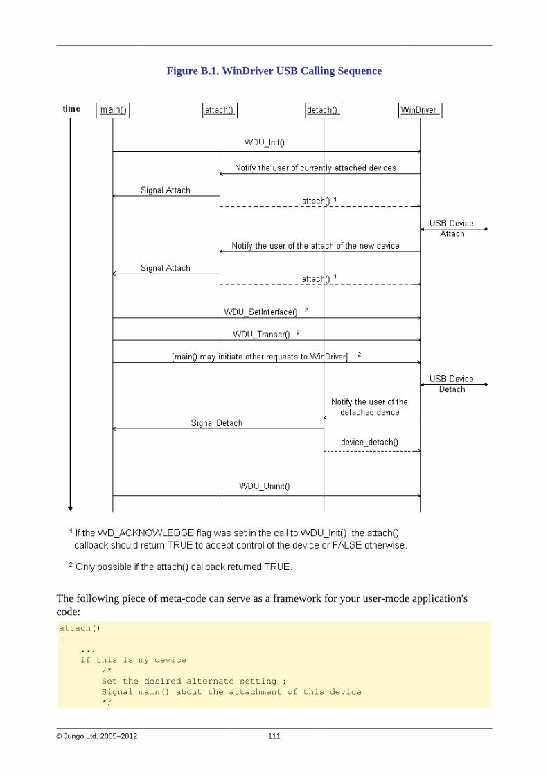
© Jungo Ltd. 2005–2012 111
Figure B.1. WinDriver USB Calling Sequence
The following piece of meta-code can serve as a framework for your user-mode application'scode:attach(){ ... if this is my device /* Set the desired alternate setting ; Signal main() about the attachment of this device */
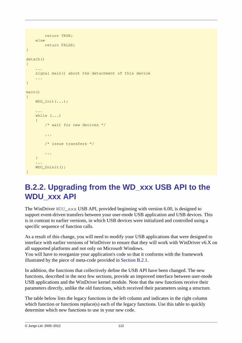
© Jungo Ltd. 2005–2012 112
return TRUE; else return FALSE;}
detach(){ ... signal main() about the detachment of this device ...}
main(){ WDU_Init(...);
... while (...) { /* wait for new devices */
...
/* issue transfers */
... } ... WDU_Uninit();}
B.2.2. Upgrading from the WD_xxx USB API to theWDU_xxx APIThe WinDriver WDU_xxx USB API, provided beginning with version 6.00, is designed tosupport event-driven transfers between your user-mode USB application and USB devices. Thisis in contrast to earlier versions, in which USB devices were initialized and controlled using aspecific sequence of function calls.
As a result of this change, you will need to modify your USB applications that were designed tointerface with earlier versions of WinDriver to ensure that they will work with WinDriver v6.X onall supported platforms and not only on Microsoft Windows.You will have to reorganize your application's code so that it conforms with the frameworkillustrated by the piece of meta-code provided in Section B.2.1.
In addition, the functions that collectively define the USB API have been changed. The newfunctions, described in the next few sections, provide an improved interface between user-modeUSB applications and the WinDriver kernel module. Note that the new functions receive theirparameters directly, unlike the old functions, which received their parameters using a structure.
The table below lists the legacy functions in the left column and indicates in the right columnwhich function or functions replace(s) each of the legacy functions. Use this table to quicklydetermine which new functions to use in your new code.
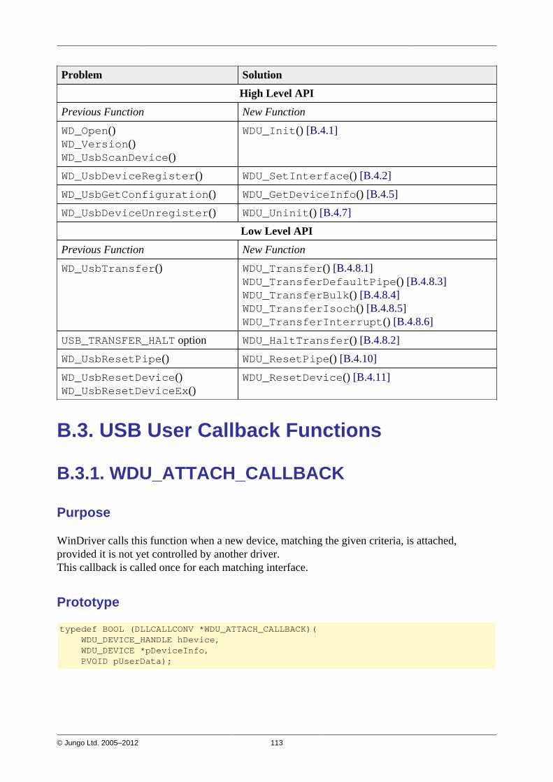
© Jungo Ltd. 2005–2012 113
Problem Solution
High Level API
Previous Function New Function
WD_Open()WD_Version()WD_UsbScanDevice()
WDU_Init() [B.4.1]
WD_UsbDeviceRegister() WDU_SetInterface() [B.4.2]
WD_UsbGetConfiguration() WDU_GetDeviceInfo() [B.4.5]
WD_UsbDeviceUnregister() WDU_Uninit() [B.4.7]
Low Level API
Previous Function New Function
WD_UsbTransfer() WDU_Transfer() [B.4.8.1]WDU_TransferDefaultPipe() [B.4.8.3]WDU_TransferBulk() [B.4.8.4]WDU_TransferIsoch() [B.4.8.5]WDU_TransferInterrupt() [B.4.8.6]
USB_TRANSFER_HALT option WDU_HaltTransfer() [B.4.8.2]
WD_UsbResetPipe() WDU_ResetPipe() [B.4.10]
WD_UsbResetDevice()WD_UsbResetDeviceEx()
WDU_ResetDevice() [B.4.11]
B.3. USB User Callback Functions
B.3.1. WDU_ATTACH_CALLBACK
Purpose
WinDriver calls this function when a new device, matching the given criteria, is attached,provided it is not yet controlled by another driver.This callback is called once for each matching interface.
Prototype
typedef BOOL (DLLCALLCONV *WDU_ATTACH_CALLBACK)( WDU_DEVICE_HANDLE hDevice, WDU_DEVICE *pDeviceInfo, PVOID pUserData);

© Jungo Ltd. 2005–2012 114
Parameters
Name Type Input/Output
hDevice WDU_DEVICE_HANDLE Input
pDeviceInfo WDU_DEVICE* Input
pUserData PVOID Input
Description
Name Description
hDevice A unique identifier for the device/interface
pDeviceInfo Pointer to a USB device information structure [B.5.2.3]; Valid until theend of the function
pUserData Pointer to user-mode data for the callback, as passed toWDU_Init() [B.4.1] within the event table parameter(pEventTable->pUserData)
Return Value
If the WD_ACKNOWLEDGE flag was set in the call to WDU_Init() [B.4.1] (within thedwOptions parameter), the callback function should check if it wants to control the device, andif so return TRUE (otherwise — return FALSE).If the WD_ACKNOWLEDGE flag was not set in the call to WDU_Init(), then the return value ofthe callback function is insignificant.
B.3.2. WDU_DETACH_CALLBACK
Purpose
WinDriver calls this function when a controlled device has been detached from the system.
Prototype
typedef void (DLLCALLCONV *WDU_DETACH_CALLBACK)( WDU_DEVICE_HANDLE hDevice, PVOID pUserData);
Parameters
Name Type Input/Output
hDevice WDU_DEVICE_HANDLE Input
pUserData PVOID Input

© Jungo Ltd. 2005–2012 115
Description
Name Description
hDevice A unique identifier for the device/interface
pUserData Pointer to user-mode data for the callback, as passed toWDU_Init() [B.4.1] within the event table parameter(pEventTable->pUserData)
Return Value
None
B.3.3. WDU_POWER_CHANGE_CALLBACK
Purpose
WinDriver calls this function when a controlled device has changed its power settings.
Prototype
typedef BOOL (DLLCALLCONV *WDU_POWER_CHANGE_CALLBACK)( WDU_DEVICE_HANDLE hDevice, DWORD dwPowerState, PVOID pUserData);
Parameters
Name Type Input/Output
dwPowerState DWORD Input
pUserData PVOID Input
Description
Name Description
hDevice A unique identifier for the device/interface
dwPowerState Number of the power state selected
pUserData Pointer to user-mode data for the callback, as passed toWDU_Init() [B.4.1] within the event table parameter(pEventTable->pUserData)
Return Value
TRUE/FALSE. Currently there is no significance to the return value.
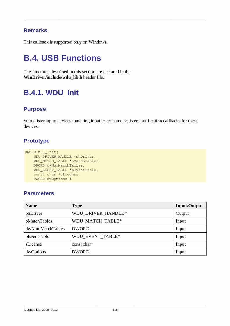
© Jungo Ltd. 2005–2012 116
Remarks
This callback is supported only on Windows.
B.4. USB FunctionsThe functions described in this section are declared in theWinDriver/include/wdu_lib.h header file.
B.4.1. WDU_Init
Purpose
Starts listening to devices matching input criteria and registers notification callbacks for thesedevices.
Prototype
DWORD WDU_Init( WDU_DRIVER_HANDLE *phDriver, WDU_MATCH_TABLE *pMatchTables, DWORD dwNumMatchTables, WDU_EVENT_TABLE *pEventTable, const char *sLicense, DWORD dwOptions);
Parameters
Name Type Input/Output
phDriver WDU_DRIVER_HANDLE * Output
pMatchTables WDU_MATCH_TABLE* Input
dwNumMatchTables DWORD Input
pEventTable WDU_EVENT_TABLE* Input
sLicense const char* Input
dwOptions DWORD Input
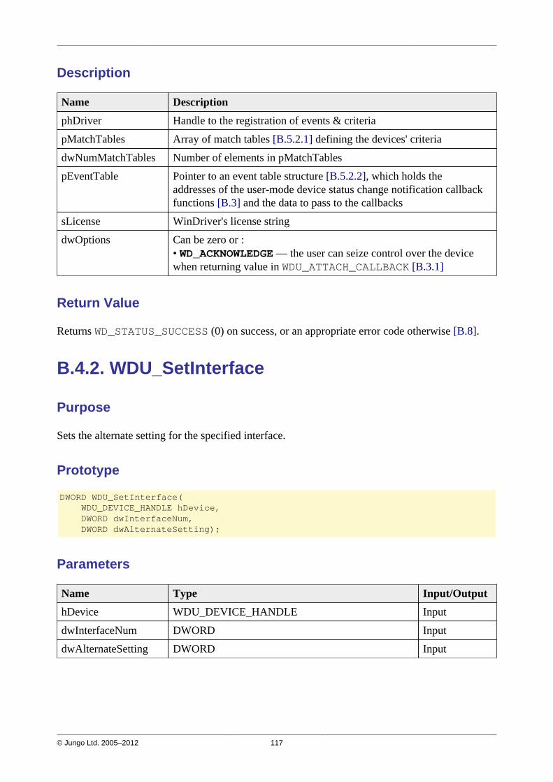
© Jungo Ltd. 2005–2012 117
Description
Name Description
phDriver Handle to the registration of events & criteria
pMatchTables Array of match tables [B.5.2.1] defining the devices' criteria
dwNumMatchTables Number of elements in pMatchTables
pEventTable Pointer to an event table structure [B.5.2.2], which holds theaddresses of the user-mode device status change notification callbackfunctions [B.3] and the data to pass to the callbacks
sLicense WinDriver's license string
dwOptions Can be zero or :• WD_ACKNOWLEDGE — the user can seize control over the devicewhen returning value in WDU_ATTACH_CALLBACK [B.3.1]
Return Value
Returns WD_STATUS_SUCCESS (0) on success, or an appropriate error code otherwise [B.8].
B.4.2. WDU_SetInterface
Purpose
Sets the alternate setting for the specified interface.
Prototype
DWORD WDU_SetInterface( WDU_DEVICE_HANDLE hDevice, DWORD dwInterfaceNum, DWORD dwAlternateSetting);
Parameters
Name Type Input/Output
hDevice WDU_DEVICE_HANDLE Input
dwInterfaceNum DWORD Input
dwAlternateSetting DWORD Input
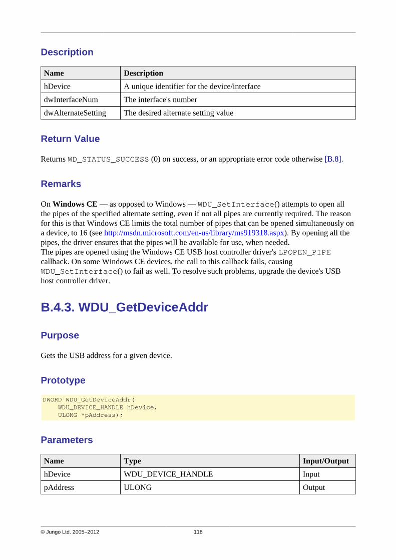
© Jungo Ltd. 2005–2012 118
Description
Name Description
hDevice A unique identifier for the device/interface
dwInterfaceNum The interface's number
dwAlternateSetting The desired alternate setting value
Return Value
Returns WD_STATUS_SUCCESS (0) on success, or an appropriate error code otherwise [B.8].
Remarks
On Windows CE — as opposed to Windows — WDU_SetInterface() attempts to open allthe pipes of the specified alternate setting, even if not all pipes are currently required. The reasonfor this is that Windows CE limits the total number of pipes that can be opened simultaneously ona device, to 16 (see http://msdn.microsoft.com/en-us/library/ms919318.aspx). By opening all thepipes, the driver ensures that the pipes will be available for use, when needed.The pipes are opened using the Windows CE USB host controller driver's LPOPEN_PIPEcallback. On some Windows CE devices, the call to this callback fails, causingWDU_SetInterface() to fail as well. To resolve such problems, upgrade the device's USBhost controller driver.
B.4.3. WDU_GetDeviceAddr
Purpose
Gets the USB address for a given device.
Prototype
DWORD WDU_GetDeviceAddr( WDU_DEVICE_HANDLE hDevice, ULONG *pAddress);
Parameters
Name Type Input/Output
hDevice WDU_DEVICE_HANDLE Input
pAddress ULONG Output
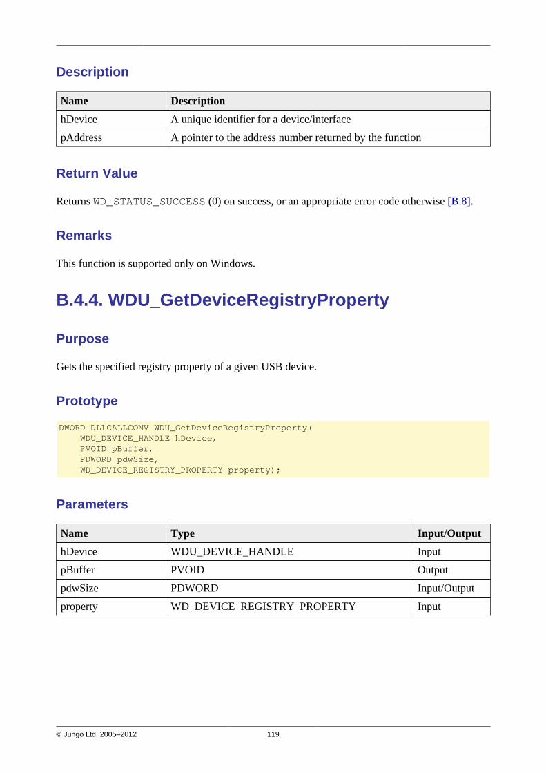
© Jungo Ltd. 2005–2012 119
Description
Name Description
hDevice A unique identifier for a device/interface
pAddress A pointer to the address number returned by the function
Return Value
Returns WD_STATUS_SUCCESS (0) on success, or an appropriate error code otherwise [B.8].
Remarks
This function is supported only on Windows.
B.4.4. WDU_GetDeviceRegistryProperty
Purpose
Gets the specified registry property of a given USB device.
Prototype
DWORD DLLCALLCONV WDU_GetDeviceRegistryProperty( WDU_DEVICE_HANDLE hDevice, PVOID pBuffer, PDWORD pdwSize, WD_DEVICE_REGISTRY_PROPERTY property);
Parameters
Name Type Input/Output
hDevice WDU_DEVICE_HANDLE Input
pBuffer PVOID Output
pdwSize PDWORD Input/Output
property WD_DEVICE_REGISTRY_PROPERTY Input

© Jungo Ltd. 2005–2012 120
Description
Name Description
hDevice A unique identifier of the device/interface
pBuffer Pointer to a user allocated buffer to be filled with the requested registryproperty. The function will fill the buffer only if the buffer size, asindicated in the input value of the pdwSize parameter, is sufficient —i.e., >= the property's size, as returned via pdwSize.pBuffer can be set to NULL when using the function only to retrievethe size of the registry property (see pdwSize).
pdwSize As input, points to a value indicating the size of the user-suppliedbuffer (pBuffer); if pBuffer is set to NULL, the input value of thisparameter is ignored.As output, points to a value indicating the required buffer size forstoring the registry property.
property The ID of the registry property to be retrieved — see the description ofthe WD_DEVICE_REGISTRY_PROPERTY enumeration [B.5.1].Note: String registry properties are in WCHAR format.
Return Value
Returns WD_STATUS_SUCCESS (0) on success, or an appropriate error code otherwise [B.8].
Remarks
• When the size of the provided user buffer (pBuffer ) — *pdwSize (input)— is not sufficient to hold the requested registry property, the function returnsWD_INVALID_PARAMETER.
• This function is supported only on Windows.
B.4.5. WDU_GetDeviceInfo
Purpose
Gets configuration information from a device, including all the device descriptors.
NOTE: The caller to this function is responsible for calling WDU_PutDeviceInfo() [B.4.6] inorder to free the *ppDeviceInfo pointer returned by the function.
Prototype
DWORD WDU_GetDeviceInfo( WDU_DEVICE_HANDLE hDevice, WDU_DEVICE **ppDeviceInfo);

© Jungo Ltd. 2005–2012 121
Parameters
Name Type Input/Output
hDevice WDU_DEVICE_HANDLE Input
ppDeviceInfo WDU_DEVICE** Output
Description
Name Description
hDevice A unique identifier for a device/interface
ppDeviceInfo Pointer to pointer to a USB device information structure [B.5.2.3]
Return Value
Returns WD_STATUS_SUCCESS (0) on success, or an appropriate error code otherwise [B.8].
B.4.6. WDU_PutDeviceInfo
Purpose
Receives a device information pointer, allocated with a previousWDU_GetDeviceInfo() [B.4.5] call, in order to perform the necessary cleanup.
Prototype
void WDU_PutDeviceInfo(WDU_DEVICE *pDeviceInfo);
Parameters
Name Type Input/Output
pDeviceInfo WDU_DEVICE* Input
Description
Name Description
pDeviceInfo Pointer to a USB device information structure [B.5.2.3], as returned bya previous call to WDU_GetDeviceInfo() [B.4.5]
Return Value
None
© Jungo Ltd. 2005–2012 122
B.4.7. WDU_Uninit
Purpose
Stops listening to devices matching a given criteria and unregisters the notification callbacks forthese devices.
Prototype
void WDU_Uninit(WDU_DRIVER_HANDLE hDriver);
Parameters
Name Type Input/Output
hDriver WDU_DRIVER_HANDLE Input
Description
Name Description
hDriver Handle to the registration received from WDU_Init() [B.4.1]
Return Value
None

© Jungo Ltd. 2005–2012 123
B.4.8. Single-Blocking Transfer Functions
This section describes WinDriver's single-blocking data transfer functions.For more information, refer to Section 9.3.2 of the manual.
B.4.8.1. WDU_Transfer
Purpose
Transfers data to or from a device.
Prototype
DWORD WDU_Transfer( WDU_DEVICE_HANDLE hDevice, DWORD dwPipeNum, DWORD fRead, DWORD dwOptions, PVOID pBuffer, DWORD dwBufferSize, PDWORD pdwBytesTransferred, PBYTE pSetupPacket, DWORD dwTimeout);
Parameters
Name Type Input/Output
hDevice WDU_DEVICE_HANDLE Input
dwPipeNum DWORD Input
fRead DWORD Input
dwOptions DWORD Input
pBuffer PVOID Input
dwBufferSize DWORD Input
pdwBytesTransferred PDWORD Output
pSetupPacket PBYTE Input
dwTimeout DWORD Input
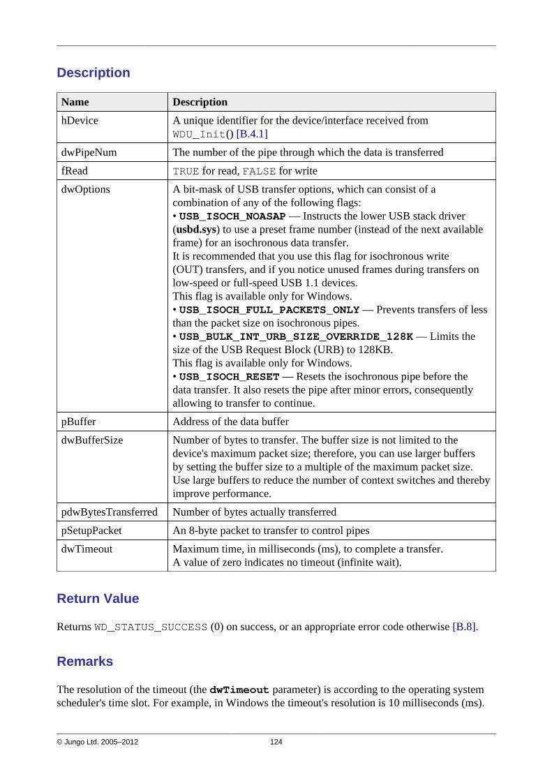
© Jungo Ltd. 2005–2012 124
Description
Name Description
hDevice A unique identifier for the device/interface received fromWDU_Init() [B.4.1]
dwPipeNum The number of the pipe through which the data is transferred
fRead TRUE for read, FALSE for write
dwOptions A bit-mask of USB transfer options, which can consist of acombination of any of the following flags:• USB_ISOCH_NOASAP — Instructs the lower USB stack driver(usbd.sys) to use a preset frame number (instead of the next availableframe) for an isochronous data transfer.It is recommended that you use this flag for isochronous write(OUT) transfers, and if you notice unused frames during transfers onlow-speed or full-speed USB 1.1 devices.This flag is available only for Windows.• USB_ISOCH_FULL_PACKETS_ONLY — Prevents transfers of lessthan the packet size on isochronous pipes.• USB_BULK_INT_URB_SIZE_OVERRIDE_128K — Limits thesize of the USB Request Block (URB) to 128KB.This flag is available only for Windows.• USB_ISOCH_RESET — Resets the isochronous pipe before thedata transfer. It also resets the pipe after minor errors, consequentlyallowing to transfer to continue.
pBuffer Address of the data buffer
dwBufferSize Number of bytes to transfer. The buffer size is not limited to thedevice's maximum packet size; therefore, you can use larger buffersby setting the buffer size to a multiple of the maximum packet size.Use large buffers to reduce the number of context switches and therebyimprove performance.
pdwBytesTransferred Number of bytes actually transferred
pSetupPacket An 8-byte packet to transfer to control pipes
dwTimeout Maximum time, in milliseconds (ms), to complete a transfer.A value of zero indicates no timeout (infinite wait).
Return Value
Returns WD_STATUS_SUCCESS (0) on success, or an appropriate error code otherwise [B.8].
Remarks
The resolution of the timeout (the dwTimeout parameter) is according to the operating systemscheduler's time slot. For example, in Windows the timeout's resolution is 10 milliseconds (ms).

© Jungo Ltd. 2005–2012 125
B.4.8.2. WDU_HaltTransfer
Purpose
Halts the transfer on the specified pipe (only one simultaneous transfer per pipe is allowed byWinDriver).
Prototype
DWORD WDU_HaltTransfer( WDU_DEVICE_HANDLE hDevice, DWORD dwPipeNum);
Parameters
Name Type Input/Output
hDevice WDU_DEVICE_HANDLE Input
dwPipeNum DWORD Input
Description
Name Description
hDevice A unique identifier for the device/interface
dwPipeNum The number of the pipe
Return Value
Returns WD_STATUS_SUCCESS (0) on success, or an appropriate error code otherwise [B.8].

© Jungo Ltd. 2005–2012 126
B.4.8.3. WDU_TransferDefaultPipe
Purpose
Transfers data to or from a device through the default control pipe (pipe 0).
Prototype
DWORD WDU_TransferDefaultPipe( WDU_DEVICE_HANDLE hDevice, DWORD fRead, DWORD dwOptions, PVOID pBuffer, DWORD dwBufferSize, PDWORD pdwBytesTransferred, PBYTE pSetupPacket, DWORD dwTimeout);
Refer to the WDU_Transfer() parameters documentation [B.4.8.1], except fordwPipeNum (N/A).
Return Value
Returns WD_STATUS_SUCCESS (0) on success, or an appropriate error code otherwise [B.8].
B.4.8.4. WDU_TransferBulk
Purpose
Performs bulk data transfer to or from a device.
Prototype
DWORD WDU_TransferBulk( WDU_DEVICE_HANDLE hDevice, DWORD dwPipeNum, DWORD fRead, DWORD dwOptions, PVOID pBuffer, DWORD dwBufferSize, PDWORD pdwBytesTransferred, DWORD dwTimeout);
Refer to the WDU_Transfer() parameters documentation [B.4.8.1], except forpSetupPacket (N/A).
Return Value
Returns WD_STATUS_SUCCESS (0) on success, or an appropriate error code otherwise [B.8].

© Jungo Ltd. 2005–2012 127
B.4.8.5. WDU_TransferIsoch
Purpose
Performs isochronous data transfer to or from a device.
Prototype
DWORD WDU_TransferIsoch( WDU_DEVICE_HANDLE hDevice, DWORD dwPipeNum, DWORD fRead, DWORD dwOptions, PVOID pBuffer, DWORD dwBufferSize, PDWORD pdwBytesTransferred, DWORD dwTimeout);
Refer to the WDU_Transfer() parameters documentation [B.4.8.1], except forpSetupPacket (N/A).
Return Value
Returns WD_STATUS_SUCCESS (0) on success, or an appropriate error code otherwise [B.8].
B.4.8.6. WDU_TransferInterrupt
Purpose
Performs interrupt data transfer to or from a device.
Prototype
DWORD WDU_TransferInterrupt( WDU_DEVICE_HANDLE hDevice, DWORD dwPipeNum, DWORD fRead, DWORD dwOptions, PVOID pBuffer, DWORD dwBufferSize, PDWORD pdwBytesTransferred, DWORD dwTimeout);
Refer to the WDU_Transfer() parameters documentation [B.4.8.1], except forpSetupPacket (N/A).
Return Value
Returns WD_STATUS_SUCCESS (0) on success, or an appropriate error code otherwise [B.8].

© Jungo Ltd. 2005–2012 128
B.4.9. Streaming Data Transfer Functions
This section describes WinDriver's streaming data transfer functions.For a detailed explanation regarding stream transfers and their implementation with Windriver,refer to Section 9.3.3 of the manual.
The streaming APIs are currently supported on Windows and Windows CE.
B.4.9.1. WDU_StreamOpen
Purpose
Opens a new stream for the specified pipe.A stream can be associated with any pipe except for the control pipe (pipe 0). The stream's datatransfer direction — read/write — is derived from the direction of its pipe.
Prototype
DWORD DLLCALLCONV WDU_StreamOpen( WDU_DEVICE_HANDLE hDevice, DWORD dwPipeNum, DWORD dwBufferSize, DWORD dwRxSize, BOOL fBlocking, DWORD dwOptions, DWORD dwRxTxTimeout, WDU_STREAM_HANDLE *phStream);
Parameters
Name Type Input/Output
hDevice WDU_DEVICE_HANDLE Input
dwPipeNum DWORD Input
dwBufferSize DWORD Input
dwRxSize DWORD Input
fBlocking BOOL Input
dwOptions DWORD Input
dwRxTxTimeout DWORD Input
phStream WDU_STREAM_HANDLE* Output

© Jungo Ltd. 2005–2012 129
Description
Name Description
hDevice A unique identifier for the device/interface
dwPipeNum The number of the pipe for which to open the stream
dwBufferSize The size, in bytes, of the stream's data buffer
dwRxSize The size, in bytes, of the data blocks that the stream reads from thedevice. This parameter is relevant only for read streams, and mustnot exceed the value of the dwBufferSize parameter. Note: Whensetting the USB_STREAM_MAX_TRANSFER_SIZE_OVERWRITEdwOptions flag, this is also the maximum transfer size.
fBlocking • TRUE for a blocking stream, which performs blocked I/O;• FALSE for a non-blocking stream, which performs non-blocking I/O.For additional information, refer to Section 9.3.3.1.
dwOptions A bit-mask of USB transfer options, which can consist of acombination of any of the following flags:• USB_ISOCH_NOASAP — Instructs the lower USB stack driver(usbd.sys) to use a preset frame number (instead of the next availableframe) for an isochronous data transfer.It is recommended that you use this flag for isochronous write(OUT) transfers, and if you notice unused frames during transfers onlow-speed or full-speed USB 1.1 devices.This flag is available only for Windows.• USB_ISOCH_FULL_PACKETS_ONLY — Prevents transfers of lessthan the packet size on isochronous pipes.• USB_BULK_INT_URB_SIZE_OVERRIDE_128K — Limits thesize of the USB Request Block (URB) to 128KB.This flag is available only for Windows.• USB_STREAM_OVERWRITE_BUFFER_WHEN_FULL — Whenthere is not enough free space in a read stream's data buffer tocomplete the transfer, overwrite old data in the buffer. This flag isapplicable only to read streams.• USB_STREAM_MAX_TRANSFER_SIZE_OVERRIDE — Overridesthe default maximum transfer size with the dwRxSize transfer size,on Windows CE. Note that setting a large dwRxSize value whenusing this flag, may cause the transfers to fail due to host controllerlimitations.This flag is applicable only to read streams on Windows CE.
dwRxTxTimeout Maximum time, in milliseconds (ms), for the completion of a datatransfer between the stream and the device.A value of zero indicates no timeout (infinite wait).
phStream Pointer to a unique identifier for the stream, to be returned by thefunction and passed to the other WDU_StreamXXX() functions
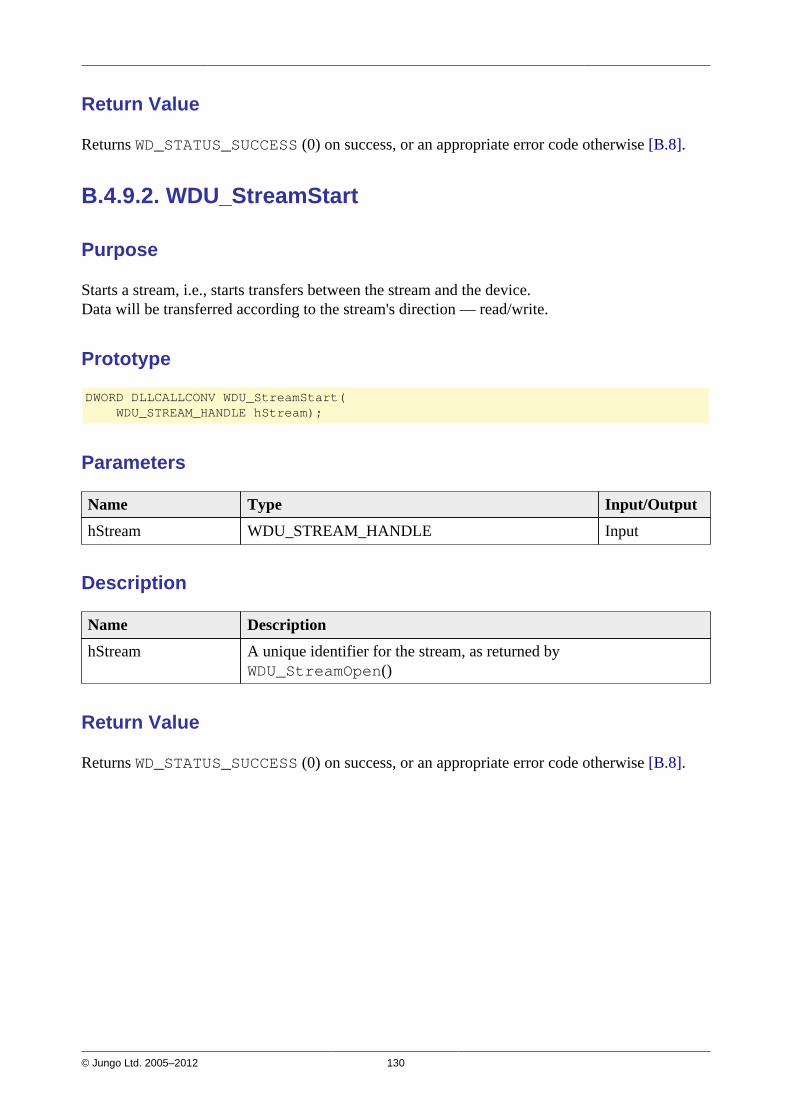
© Jungo Ltd. 2005–2012 130
Return Value
Returns WD_STATUS_SUCCESS (0) on success, or an appropriate error code otherwise [B.8].
B.4.9.2. WDU_StreamStart
Purpose
Starts a stream, i.e., starts transfers between the stream and the device.Data will be transferred according to the stream's direction — read/write.
Prototype
DWORD DLLCALLCONV WDU_StreamStart( WDU_STREAM_HANDLE hStream);
Parameters
Name Type Input/Output
hStream WDU_STREAM_HANDLE Input
Description
Name Description
hStream A unique identifier for the stream, as returned byWDU_StreamOpen()
Return Value
Returns WD_STATUS_SUCCESS (0) on success, or an appropriate error code otherwise [B.8].
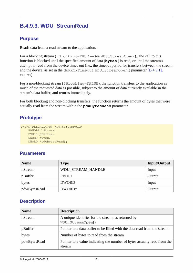
© Jungo Ltd. 2005–2012 131
B.4.9.3. WDU_StreamRead
Purpose
Reads data from a read stream to the application.
For a blocking stream (fBlocking=TRUE — see WDU_StreamOpen()), the call to thisfunction is blocked until the specified amount of data (bytes ) is read, or until the stream'sattempt to read from the device times out (i.e., the timeout period for transfers between the streamand the device, as set in the dwRxTxTimeout WDU_StreamOpen() parameter [B.4.9.1],expires).
For a non-blocking stream (fBlocking=FALSE), the function transfers to the application asmuch of the requested data as possible, subject to the amount of data currently available in thestream's data buffer, and returns immediately.
For both blocking and non-blocking transfers, the function returns the amount of bytes that wereactually read from the stream within the pdwBytesRead parameter.
Prototype
DWORD DLLCALLCONV WDU_StreamRead( HANDLE hStream, PVOID pBuffer, DWORD bytes, DWORD *pdwBytesRead);
Parameters
Name Type Input/Output
hStream WDU_STREAM_HANDLE Input
pBuffer PVOID Output
bytes DWORD Input
pdwBytesRead DWORD* Output
Description
Name Description
hStream A unique identifier for the stream, as returned byWDU_StreamOpen()
pBuffer Pointer to a data buffer to be filled with the data read from the stream
bytes Number of bytes to read from the stream
pdwBytesRead Pointer to a value indicating the number of bytes actually read from thestream

© Jungo Ltd. 2005–2012 132
Return Value
Returns WD_STATUS_SUCCESS (0) on success, or WD_OPERATION_FAILED on failure.In case of failure, call WDU_StreamGetStatus() [B.4.9.6] to get the current stream status.
B.4.9.4. WDU_StreamWrite
Purpose
Writes data from the applciation to a write stream.
For a blocking stream (fBlocking=TRUE — see WDU_StreamOpen()), the call to thisfunction is blocked until the entire data is written to the stream, or until the stream's attempt towrite to the device times out (i.e., the timeout period for transfers between the stream and thedevice, as set in the dwRxTxTimeout WDU_StreamOpen() parameter [B.4.9.1], expires).
For a non-blocking stream (fBlocking=FALSE), the function writes as much data as currentlypossible to the stream's data buffer, and returns immediately.
For both blocking and non-blocking transfers, the function returns the amount of bytes that wereactually written to the stream within the pdwBytesWritten parameter.
Prototype
DWORD DLLCALLCONV WDU_StreamWrite( HANDLE hStream, const PVOID pBuffer, DWORD bytes, DWORD *pdwBytesWritten);
Parameters
Name Type Input/Output
hStream WDU_STREAM_HANDLE Input
pBuffer const PVOID Input
bytes DWORD Input
pdwBytesWritten DWORD* Output
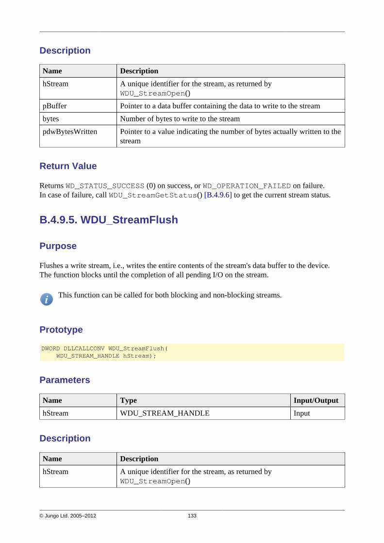
© Jungo Ltd. 2005–2012 133
Description
Name Description
hStream A unique identifier for the stream, as returned byWDU_StreamOpen()
pBuffer Pointer to a data buffer containing the data to write to the stream
bytes Number of bytes to write to the stream
pdwBytesWritten Pointer to a value indicating the number of bytes actually written to thestream
Return Value
Returns WD_STATUS_SUCCESS (0) on success, or WD_OPERATION_FAILED on failure.In case of failure, call WDU_StreamGetStatus() [B.4.9.6] to get the current stream status.
B.4.9.5. WDU_StreamFlush
Purpose
Flushes a write stream, i.e., writes the entire contents of the stream's data buffer to the device.The function blocks until the completion of all pending I/O on the stream.
This function can be called for both blocking and non-blocking streams.
Prototype
DWORD DLLCALLCONV WDU_StreamFlush( WDU_STREAM_HANDLE hStream);
Parameters
Name Type Input/Output
hStream WDU_STREAM_HANDLE Input
Description
Name Description
hStream A unique identifier for the stream, as returned byWDU_StreamOpen()
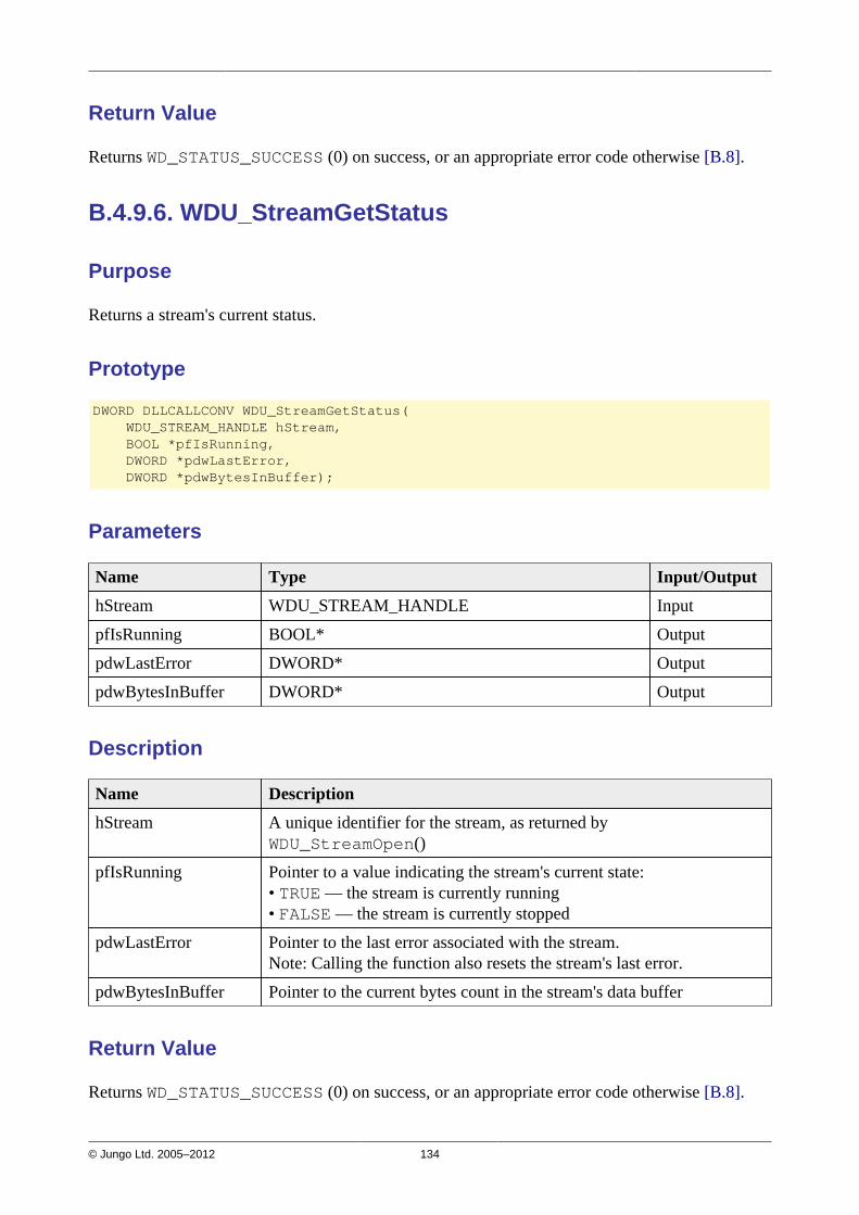
© Jungo Ltd. 2005–2012 134
Return Value
Returns WD_STATUS_SUCCESS (0) on success, or an appropriate error code otherwise [B.8].
B.4.9.6. WDU_StreamGetStatus
Purpose
Returns a stream's current status.
Prototype
DWORD DLLCALLCONV WDU_StreamGetStatus( WDU_STREAM_HANDLE hStream, BOOL *pfIsRunning, DWORD *pdwLastError, DWORD *pdwBytesInBuffer);
Parameters
Name Type Input/Output
hStream WDU_STREAM_HANDLE Input
pfIsRunning BOOL* Output
pdwLastError DWORD* Output
pdwBytesInBuffer DWORD* Output
Description
Name Description
hStream A unique identifier for the stream, as returned byWDU_StreamOpen()
pfIsRunning Pointer to a value indicating the stream's current state:• TRUE — the stream is currently running• FALSE — the stream is currently stopped
pdwLastError Pointer to the last error associated with the stream.Note: Calling the function also resets the stream's last error.
pdwBytesInBuffer Pointer to the current bytes count in the stream's data buffer
Return Value
Returns WD_STATUS_SUCCESS (0) on success, or an appropriate error code otherwise [B.8].

© Jungo Ltd. 2005–2012 135
B.4.9.7. WDU_StreamStop
Purpose
Stops an active stream, i.e., stops transfers between the stream and the device.In the case of a write stream, the function flushes the stream — i.e., writes its contents to thedevice — before stopping it.
Prototype
DWORD DLLCALLCONV WDU_StreamStop(WDU_STREAM_HANDLE hStream);
Parameters
Name Type Input/Output
hStream WDU_STREAM_HANDLE Input
Description
Name Description
hStream A unique identifier for the stream, as returned byWDU_StreamOpen()
Return Value
Returns WD_STATUS_SUCCESS (0) on success, or an appropriate error code otherwise [B.8].
B.4.9.8. WDU_StreamClose
Purpose
Closes an open stream.The function stops the stream, including flushing its data to the device (in the case of a writestream), before closing it.
Prototype
DWORD DLLCALLCONV WDU_StreamClose(WDU_STREAM_HANDLE hStream);
Parameters
Name Type Input/Output
hStream WDU_STREAM_HANDLE Input
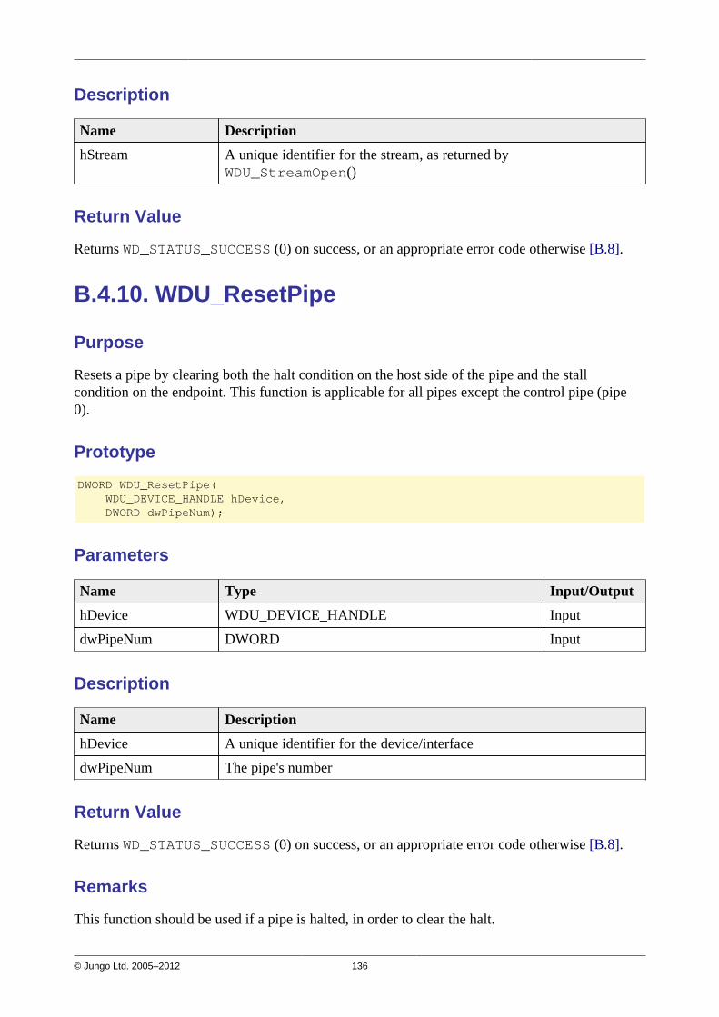
© Jungo Ltd. 2005–2012 136
Description
Name Description
hStream A unique identifier for the stream, as returned byWDU_StreamOpen()
Return Value
Returns WD_STATUS_SUCCESS (0) on success, or an appropriate error code otherwise [B.8].
B.4.10. WDU_ResetPipe
Purpose
Resets a pipe by clearing both the halt condition on the host side of the pipe and the stallcondition on the endpoint. This function is applicable for all pipes except the control pipe (pipe0).
Prototype
DWORD WDU_ResetPipe( WDU_DEVICE_HANDLE hDevice, DWORD dwPipeNum);
Parameters
Name Type Input/Output
hDevice WDU_DEVICE_HANDLE Input
dwPipeNum DWORD Input
Description
Name Description
hDevice A unique identifier for the device/interface
dwPipeNum The pipe's number
Return Value
Returns WD_STATUS_SUCCESS (0) on success, or an appropriate error code otherwise [B.8].
Remarks
This function should be used if a pipe is halted, in order to clear the halt.

© Jungo Ltd. 2005–2012 137
B.4.11. WDU_ResetDevice
Purpose
Resets a device.
Prototype
DWORD WDU_ResetDevice( WDU_DEVICE_HANDLE hDevice, DWORD dwOptions);
Parameters
Name Type Input/Output
hDevice WDU_DEVICE_HANDLE Input
dwOptions DWORD Input
Description
Name Description
hDevice A unique identifier for the device/interface.
dwOptions Can be either zero or:• WD_USB_HARD_RESET — reset the device even if it is not disabled.After using this option it is advised to set the interface device usingWDU_SetInterface() [B.4.2].• WD_USB_CYCLE_PORT — simulate unplugging and replugging ofthe device, prompting the operating system to re-enumerate the devicewithout resetting it.This option is supported only on Windows XP and higher.
Return Value
Returns WD_STATUS_SUCCESS (0) on success, or an appropriate error code otherwise [B.8].
Remarks
• WDU_ResetDevice() is supported only on Windows and Windows CE, beginning withWindows CE 5.0.The WD_USB_CYCLE_PORT option is supported on Windows XP and higher.
• The function issues a request from the Windows USB driver to reset a hub port, provided theWindows USB driver supports this feature.
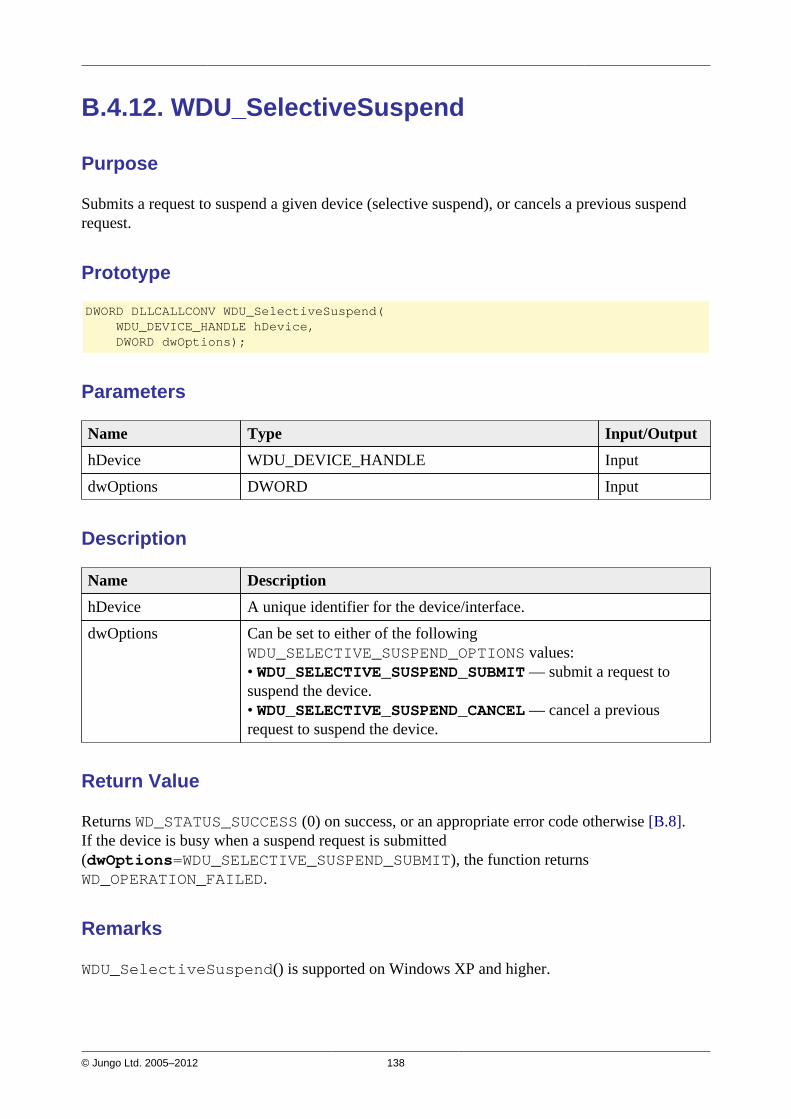
© Jungo Ltd. 2005–2012 138
B.4.12. WDU_SelectiveSuspend
Purpose
Submits a request to suspend a given device (selective suspend), or cancels a previous suspendrequest.
Prototype
DWORD DLLCALLCONV WDU_SelectiveSuspend( WDU_DEVICE_HANDLE hDevice, DWORD dwOptions);
Parameters
Name Type Input/Output
hDevice WDU_DEVICE_HANDLE Input
dwOptions DWORD Input
Description
Name Description
hDevice A unique identifier for the device/interface.
dwOptions Can be set to either of the followingWDU_SELECTIVE_SUSPEND_OPTIONS values:• WDU_SELECTIVE_SUSPEND_SUBMIT — submit a request tosuspend the device.• WDU_SELECTIVE_SUSPEND_CANCEL — cancel a previousrequest to suspend the device.
Return Value
Returns WD_STATUS_SUCCESS (0) on success, or an appropriate error code otherwise [B.8].If the device is busy when a suspend request is submitted(dwOptions=WDU_SELECTIVE_SUSPEND_SUBMIT), the function returnsWD_OPERATION_FAILED.
Remarks
WDU_SelectiveSuspend() is supported on Windows XP and higher.
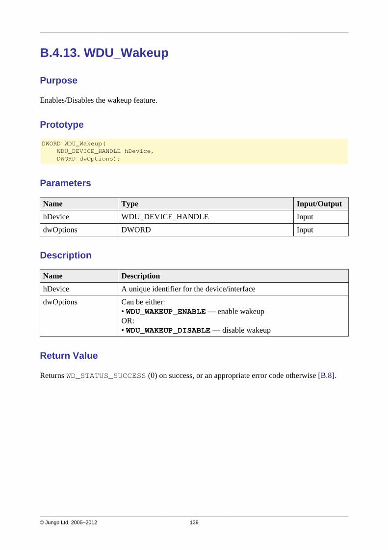
© Jungo Ltd. 2005–2012 139
B.4.13. WDU_Wakeup
Purpose
Enables/Disables the wakeup feature.
Prototype
DWORD WDU_Wakeup( WDU_DEVICE_HANDLE hDevice, DWORD dwOptions);
Parameters
Name Type Input/Output
hDevice WDU_DEVICE_HANDLE Input
dwOptions DWORD Input
Description
Name Description
hDevice A unique identifier for the device/interface
dwOptions Can be either:• WDU_WAKEUP_ENABLE — enable wakeupOR:• WDU_WAKEUP_DISABLE — disable wakeup
Return Value
Returns WD_STATUS_SUCCESS (0) on success, or an appropriate error code otherwise [B.8].

© Jungo Ltd. 2005–2012 140
B.4.14. WDU_GetLangIDs
Purpose
Reads a list of supported language IDs and/or the number of supported language IDs from adevice.
Prototype
DWORD DLLCALLCONV WDU_GetLangIDs( WDU_DEVICE_HANDLE hDevice, PBYTE pbNumSupportedLangIDs, WDU_LANGID *pLangIDs, BYTE bNumLangIDs);
Parameters
Name Type Input/Output
hDevice WDU_DEVICE_HANDLE Input
pbNumSupportedLangIDs PBYTE Output
pLangIDs WDU_LANGID* Output
bNumLangIDs BYTE Input
Description
Name Description
hDevice A unique identifier for the device/interface
pbNumSupportedLangIDs Parameter to receive number of supported language IDs
pLangIDs Array of language IDs. If bNumLangIDs is not zero the functionwill fill this array with the supported language IDs for the device.
bNumLangIDs Number of IDs in the pLangIDs array
Return Value
Returns WD_STATUS_SUCCESS (0) on success, or an appropriate error code otherwise [B.8].
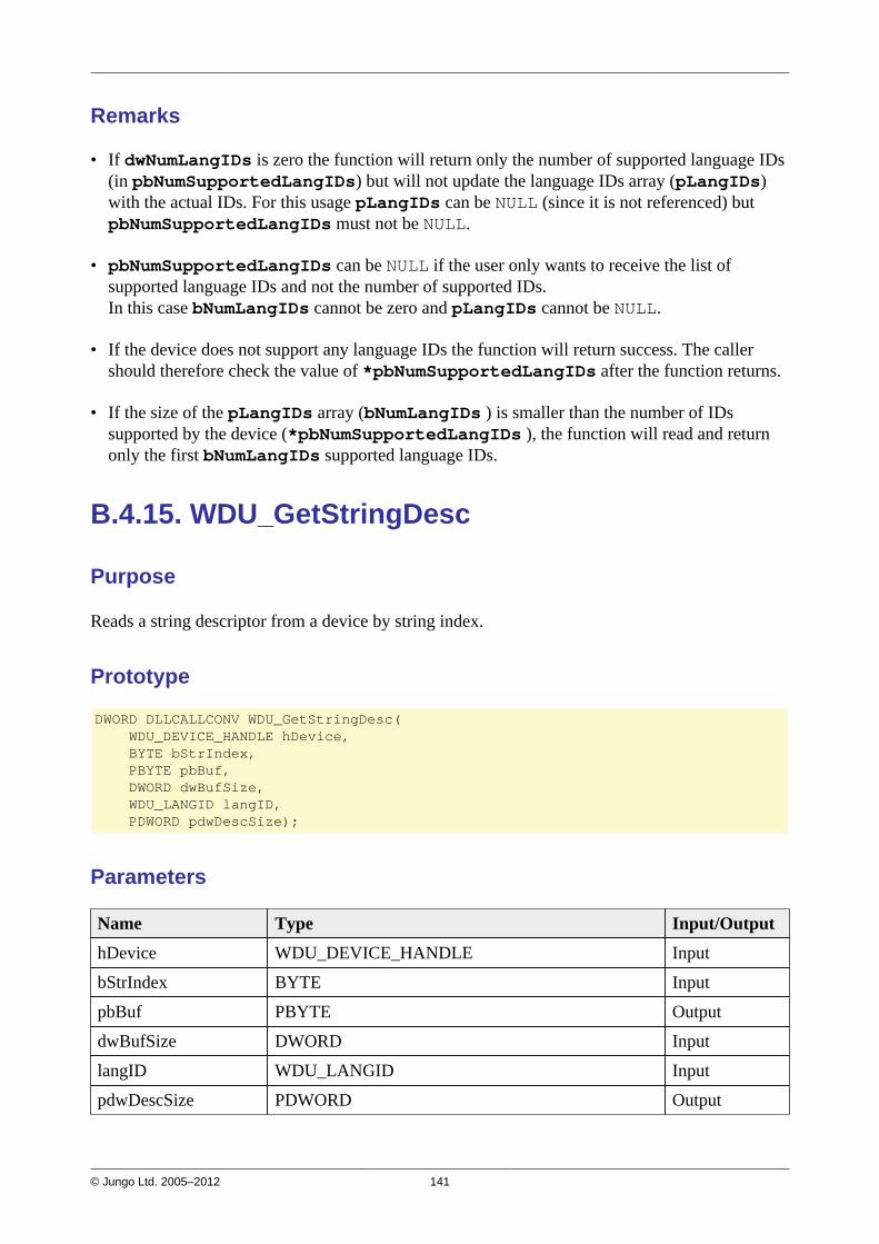
© Jungo Ltd. 2005–2012 141
Remarks
• If dwNumLangIDs is zero the function will return only the number of supported language IDs(in pbNumSupportedLangIDs) but will not update the language IDs array (pLangIDs)with the actual IDs. For this usage pLangIDs can be NULL (since it is not referenced) butpbNumSupportedLangIDs must not be NULL.
• pbNumSupportedLangIDs can be NULL if the user only wants to receive the list ofsupported language IDs and not the number of supported IDs.In this case bNumLangIDs cannot be zero and pLangIDs cannot be NULL.
• If the device does not support any language IDs the function will return success. The callershould therefore check the value of *pbNumSupportedLangIDs after the function returns.
• If the size of the pLangIDs array (bNumLangIDs ) is smaller than the number of IDssupported by the device (*pbNumSupportedLangIDs ), the function will read and returnonly the first bNumLangIDs supported language IDs.
B.4.15. WDU_GetStringDesc
Purpose
Reads a string descriptor from a device by string index.
Prototype
DWORD DLLCALLCONV WDU_GetStringDesc( WDU_DEVICE_HANDLE hDevice, BYTE bStrIndex, PBYTE pbBuf, DWORD dwBufSize, WDU_LANGID langID, PDWORD pdwDescSize);
Parameters
Name Type Input/Output
hDevice WDU_DEVICE_HANDLE Input
bStrIndex BYTE Input
pbBuf PBYTE Output
dwBufSize DWORD Input
langID WDU_LANGID Input
pdwDescSize PDWORD Output
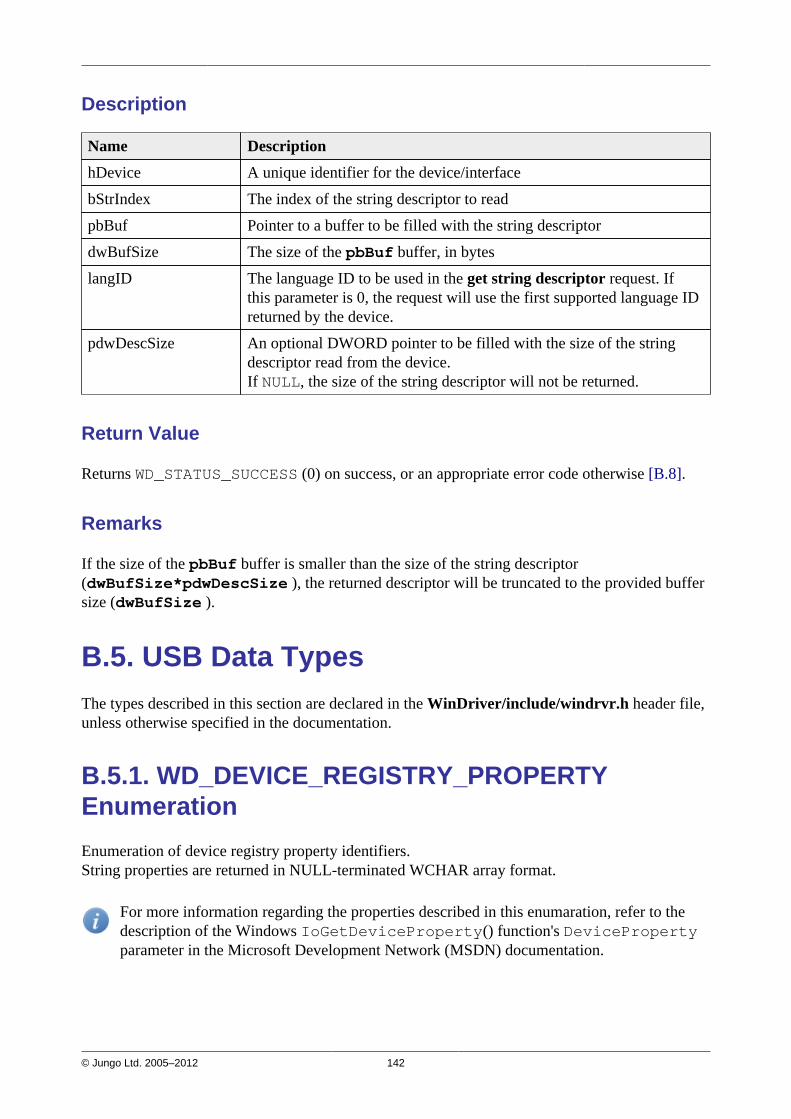
© Jungo Ltd. 2005–2012 142
Description
Name Description
hDevice A unique identifier for the device/interface
bStrIndex The index of the string descriptor to read
pbBuf Pointer to a buffer to be filled with the string descriptor
dwBufSize The size of the pbBuf buffer, in bytes
langID The language ID to be used in the get string descriptor request. Ifthis parameter is 0, the request will use the first supported language IDreturned by the device.
pdwDescSize An optional DWORD pointer to be filled with the size of the stringdescriptor read from the device.If NULL, the size of the string descriptor will not be returned.
Return Value
Returns WD_STATUS_SUCCESS (0) on success, or an appropriate error code otherwise [B.8].
Remarks
If the size of the pbBuf buffer is smaller than the size of the string descriptor(dwBufSize*pdwDescSize ), the returned descriptor will be truncated to the provided buffersize (dwBufSize ).
B.5. USB Data TypesThe types described in this section are declared in the WinDriver/include/windrvr.h header file,unless otherwise specified in the documentation.
B.5.1. WD_DEVICE_REGISTRY_PROPERTYEnumeration
Enumeration of device registry property identifiers.String properties are returned in NULL-terminated WCHAR array format.
For more information regarding the properties described in this enumaration, refer to thedescription of the Windows IoGetDeviceProperty() function's DevicePropertyparameter in the Microsoft Development Network (MSDN) documentation.

© Jungo Ltd. 2005–2012 143
Enum Value Description
WdDevicePropertyDeviceDescription Device description
WdDevicePropertyHardwareID The device's hardware IDs
WdDevicePropertyCompatibleIDs The device's compatible IDs
WdDevicePropertyBootConfiguration The hardware resources assigned to thedevice by the firmware, in raw data form
WdDevicePropertyBootConfigurationTranslated The hardware resources assigned to thedevice by the firmware, in translated form
WdDevicePropertyClassName The name of the device's setup class, in textformat
WdDevicePropertyClassGuid The GUID for the device's setup class (stringformat)
WdDevicePropertyDriverKeyName The name of the driver-specific registry key
WdDevicePropertyManufacturer Device manufacturer string
WdDevicePropertyFriendlyName Friendly device name (typically defined bythe class installer), which can be used todistinguish between two similar devices
WdDevicePropertyLocationInformation Information about the device's Location onthe bus (string format).The interpertation of this information is bus-specific.
WdDevicePropertyPhysicalDeviceObjectName The name of the Physical Device Object(PDO) for the device
WdDevicePropertyBusTypeGuid The GUID for the bus to which the device isconnected
WdDevicePropertyLegacyBusType The bus type (e.g., PCIBus or PCMCIABus)
WdDevicePropertyBusNumber The legacy bus number of the bus to whichthe device is connected
WdDevicePropertyEnumeratorName The name of the device's enumerator (e.g.,"PCI" or "root")
WdDevicePropertyAddress The device's bus address.The interpertation of this address is bus-specific.
WdDevicePropertyUINumber A number associated with the device thatcan be displayed in the user interface
WdDevicePropertyInstallState The device's installation state
WdDevicePropertyRemovalPolicy The device's current removal policy(Windows XP and later)

© Jungo Ltd. 2005–2012 144
B.5.2. USB Structures
The following figure depicts the structure hierarchy used by WinDriver's USB API. The arrayssituated in each level of the hierarchy may contain more elements than are depicted in thediagram. Arrows are used to represent pointers. In the interest of clarity, only one structure ateach level of the hierarchy is depicted in full detail (with all of its elements listed and pointersfrom it pictured).
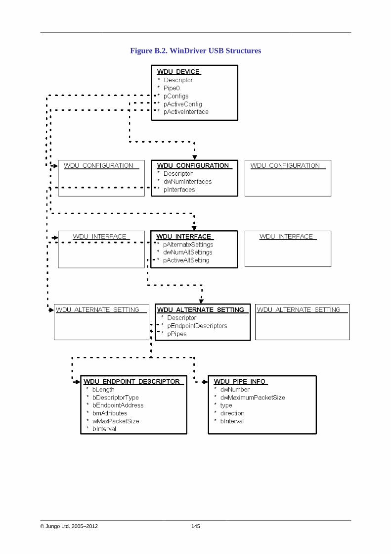
© Jungo Ltd. 2005–2012 145
Figure B.2. WinDriver USB Structures
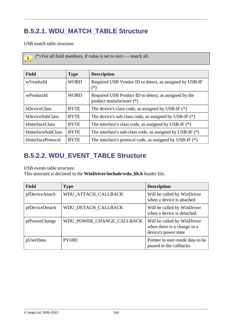
© Jungo Ltd. 2005–2012 146
B.5.2.1. WDU_MATCH_TABLE Structure
USB match table structure.
(*) For all field members, if value is set to zero — match all.
Field Type Description
wVendorId WORD Required USB Vendor ID to detect, as assigned by USB-IF(*)
wProductId WORD Required USB Product ID to detect, as assigned by theproduct manufacturer (*)
bDeviceClass BYTE The device's class code, as assigned by USB-IF (*)
bDeviceSubClass BYTE The device's sub-class code, as assigned by USB-IF (*)
bInterfaceClass BYTE The interface's class code, as assigned by USB-IF (*)
bInterfaceSubClass BYTE The interface's sub-class code, as assigned by USB-IF (*)
bInterfaceProtocol BYTE The interface's protocol code, as assigned by USB-IF (*)
B.5.2.2. WDU_EVENT_TABLE Structure
USB events table structure.This structure is declared in the WinDriver/include/wdu_lib.h header file.
Field Type Description
pfDeviceAttach WDU_ATTACH_CALLBACK Will be called by WinDriverwhen a device is attached
pfDeviceDetach WDU_DETACH_CALLBACK Will be called by WinDriverwhen a device is detached
pfPowerChange WDU_POWER_CHANGE_CALLBACK Will be called by WinDriverwhen there is a change in adevice's power state
pUserData PVOID Pointer to user-mode data to bepassed to the callbacks
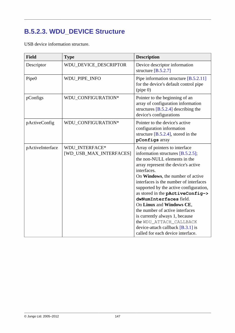
© Jungo Ltd. 2005–2012 147
B.5.2.3. WDU_DEVICE Structure
USB device information structure.
Field Type Description
Descriptor WDU_DEVICE_DESCRIPTOR Device descriptor informationstructure [B.5.2.7]
Pipe0 WDU_PIPE_INFO Pipe information structure [B.5.2.11]for the device's default control pipe(pipe 0)
pConfigs WDU_CONFIGURATION* Pointer to the beginning of anarray of configuration informationstructures [B.5.2.4] describing thedevice's configurations
pActiveConfig WDU_CONFIGURATION* Pointer to the device's activeconfiguration informationstructure [B.5.2.4], stored in thepConfigs array
pActiveInterface WDU_INTERFACE*[WD_USB_MAX_INTERFACES]
Array of pointers to interfaceinformation structures [B.5.2.5];the non-NULL elements in thearray represent the device's activeinterfaces.On Windows, the number of activeinterfaces is the number of interfacessupported by the active configuration,as stored in the pActiveConfig->dwNumInterfaces field.On Linux and Windows CE,the number of active interfacesis currently always 1, becausethe WDU_ATTACH_CALLBACKdevice-attach callback [B.3.1] iscalled for each device interface.
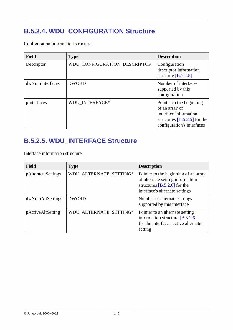
© Jungo Ltd. 2005–2012 148
B.5.2.4. WDU_CONFIGURATION Structure
Configuration information structure.
Field Type Description
Descriptor WDU_CONFIGURATION_DESCRIPTOR Configurationdescriptor informationstructure [B.5.2.8]
dwNumInterfaces DWORD Number of interfacessupported by thisconfiguration
pInterfaces WDU_INTERFACE* Pointer to the beginningof an array ofinterface informationstructures [B.5.2.5] for theconfiguration's interfaces
B.5.2.5. WDU_INTERFACE Structure
Interface information structure.
Field Type Description
pAlternateSettings WDU_ALTERNATE_SETTING* Pointer to the beginning of an arrayof alternate setting informationstructures [B.5.2.6] for theinterface's alternate settings
dwNumAltSettings DWORD Number of alternate settingssupported by this interface
pActiveAltSetting WDU_ALTERNATE_SETTING* Pointer to an alternate settinginformation structure [B.5.2.6]for the interface's active alternatesetting

© Jungo Ltd. 2005–2012 149
B.5.2.6. WDU_ALTERNATE_SETTING Structure
Alternate setting information structure.
Field Type Description
Descriptor WDU_INTERFACE_DESCRIPTOR Interface descriptorinformationstructure [B.5.2.9]
pEndpointDescriptors WDU_ENDPOINT_DESCRIPTOR* Pointer to the beginningof an array of endpointdescriptor informationstructures [B.5.2.10] for thealternate setting's endpoints
pPipes WDU_PIPE_INFO* Pointer to the beginning ofan array of pipe informationstructures [B.5.2.11] for thealternate setting's pipes
B.5.2.7. WDU_DEVICE_DESCRIPTOR Structure
USB device descriptor information structure.
Field Type Description
bLength UCHAR Size, in bytes, of the descriptor (18 bytes)
bDescriptorType UCHAR Device descriptor (0x01)
bcdUSB USHORT Number of the USB specification with which the devicecomplies
bDeviceClass UCHAR The device's class
bDeviceSubClass UCHAR The device's sub-class
bDeviceProtocol UCHAR The device's protocol
bMaxPacketSize0 UCHAR Maximum size of transferred packets
idVendor USHORT Vendor ID, as assigned by USB-IF
idProduct USHORT Product ID, as assigned by the product manufacturer
bcdDevice USHORT Device release number
iManufacturer UCHAR Index of manufacturer string descriptor
iProduct UCHAR Index of product string descriptor
iSerialNumber UCHAR Index of serial number string descriptor
bNumConfigurations UCHAR Number of possible configurations

© Jungo Ltd. 2005–2012 150
B.5.2.8. WDU_CONFIGURATION_DESCRIPTOR Structure
USB configuration descriptor information structure.
Field Type Description
bLength UCHAR Size, in bytes, of the descriptor
bDescriptorType UCHAR Configuration descriptor (0x02)
wTotalLength USHORT Total length, in bytes, of data returned
bNumInterfaces UCHAR Number of interfaces
bConfigurationValue UCHAR Configuration number
iConfiguration UCHAR Index of string descriptor that describes this configuration
bmAttributes UCHAR Power settings for this configuration:• D6 — self-powered• D5 — remote wakeup (allows device to wake up thehost)
MaxPower UCHAR Maximum power consumption for this configuration, in2mA units
B.5.2.9. WDU_INTERFACE_DESCRIPTOR Structure
USB interface descriptor information structure.
Field Type Description
bLength UCHAR Size, in bytes, of the descriptor (9 bytes)
bDescriptorType UCHAR Interface descriptor (0x04)
bInterfaceNumber UCHAR Interface number
bAlternateSetting UCHAR Alternate setting number
bNumEndpoints UCHAR Number of endpoints used by this interface
bInterfaceClass UCHAR The interface's class code, as assigned by USB-IF
bInterfaceSubClass UCHAR The interface's sub-class code, as assigned by USB-IF
bInterfaceProtocol UCHAR The interface's protocol code, as assigned by USB-IF
iInterface UCHAR Index of string descriptor that describes this interface
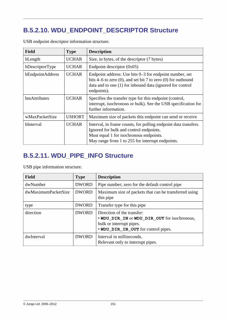
© Jungo Ltd. 2005–2012 151
B.5.2.10. WDU_ENDPOINT_DESCRIPTOR Structure
USB endpoint descriptor information structure.
Field Type Description
bLength UCHAR Size, in bytes, of the descriptor (7 bytes)
bDescriptorType UCHAR Endpoint descriptor (0x05)
bEndpointAddress UCHAR Endpoint address: Use bits 0–3 for endpoint number, setbits 4–6 to zero (0), and set bit 7 to zero (0) for outbounddata and to one (1) for inbound data (ignored for controlendpoints).
bmAttributes UCHAR Specifies the transfer type for this endpoint (control,interrupt, isochronous or bulk). See the USB specification forfurther information.
wMaxPacketSize USHORT Maximum size of packets this endpoint can send or receive
bInterval UCHAR Interval, in frame counts, for polling endpoint data transfers.Ignored for bulk and control endpoints.Must equal 1 for isochronous endpoints.May range from 1 to 255 for interrupt endpoints.
B.5.2.11. WDU_PIPE_INFO Structure
USB pipe information structure.
Field Type Description
dwNumber DWORD Pipe number; zero for the default control pipe
dwMaximumPacketSize DWORD Maximum size of packets that can be transferred usingthis pipe
type DWORD Transfer type for this pipe
direction DWORD Direction of the transfer:• WDU_DIR_IN or WDU_DIR_OUT for isochronous,bulk or interrupt pipes.• WDU_DIR_IN_OUT for control pipes.
dwInterval DWORD Interval in milliseconds.Relevant only to interrupt pipes.
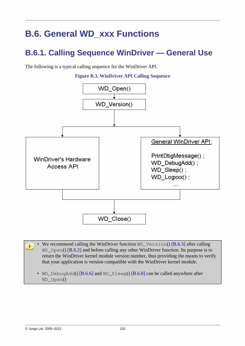
© Jungo Ltd. 2005–2012 152
B.6. General WD_xxx Functions
B.6.1. Calling Sequence WinDriver — General Use
The following is a typical calling sequence for the WinDriver API.
Figure B.3. WinDriver API Calling Sequence
• We recommend calling the WinDriver function WD_Version() [B.6.3] after callingWD_Open() [B.6.2] and before calling any other WinDriver function. Its purpose is toreturn the WinDriver kernel module version number, thus providing the means to verifythat your application is version compatible with the WinDriver kernel module.
• WD_DebugAdd() [B.6.6] and WD_Sleep() [B.6.8] can be called anywhere afterWD_Open()
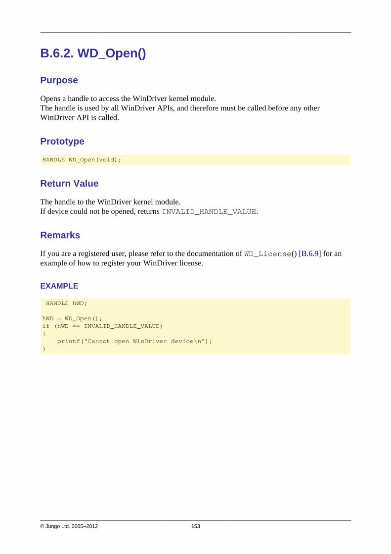
© Jungo Ltd. 2005–2012 153
B.6.2. WD_Open()
Purpose
Opens a handle to access the WinDriver kernel module.The handle is used by all WinDriver APIs, and therefore must be called before any otherWinDriver API is called.
Prototype
HANDLE WD_Open(void);
Return Value
The handle to the WinDriver kernel module.If device could not be opened, returns INVALID_HANDLE_VALUE.
Remarks
If you are a registered user, please refer to the documentation of WD_License() [B.6.9] for anexample of how to register your WinDriver license.
EXAMPLE
HANDLE hWD;
hWD = WD_Open();if (hWD == INVALID_HANDLE_VALUE){ printf("Cannot open WinDriver device\n");}
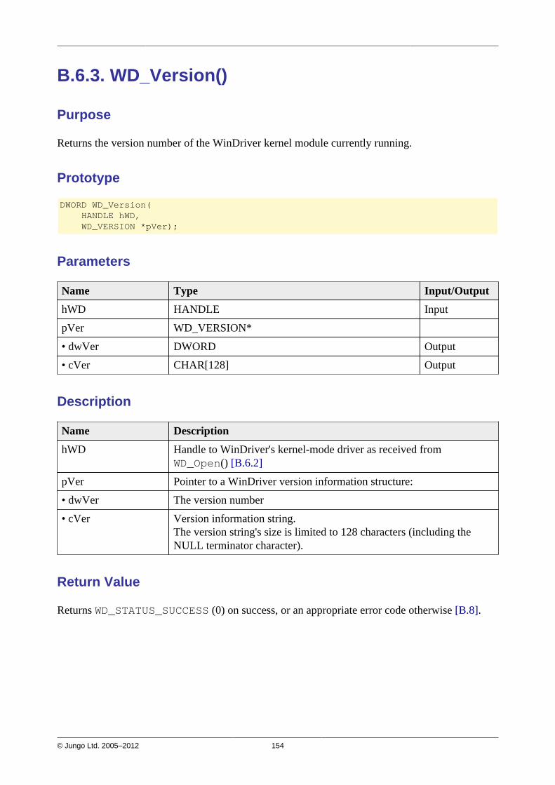
© Jungo Ltd. 2005–2012 154
B.6.3. WD_Version()
Purpose
Returns the version number of the WinDriver kernel module currently running.
Prototype
DWORD WD_Version( HANDLE hWD, WD_VERSION *pVer);
Parameters
Name Type Input/Output
hWD HANDLE Input
pVer WD_VERSION*
• dwVer DWORD Output
• cVer CHAR[128] Output
Description
Name Description
hWD Handle to WinDriver's kernel-mode driver as received fromWD_Open() [B.6.2]
pVer Pointer to a WinDriver version information structure:
• dwVer The version number
• cVer Version information string.The version string's size is limited to 128 characters (including theNULL terminator character).
Return Value
Returns WD_STATUS_SUCCESS (0) on success, or an appropriate error code otherwise [B.8].

© Jungo Ltd. 2005–2012 155
EXAMPLE
WD_VERSION ver;
BZERO(ver);WD_Version(hWD, &ver);printf("%s\n", ver.cVer);if (ver.dwVer < WD_VER){ printf("Error - incorrect WinDriver version\n");}
B.6.4. WD_Close()
Purpose
Closes the access to the WinDriver kernel module.
Prototype
void WD_Close(HANDLE hWD);
Parameters
Name Type Input/Output
hWD HANDLE Input
Description
Name Description
hWD Handle to WinDriver's kernel-mode driver as received fromWD_Open() [B.6.2]
Return Value
None
Remarks
This function must be called when you finish using WinDriver kernel module.
EXAMPLE
WD_Close(hWD);

© Jungo Ltd. 2005–2012 156
B.6.5. WD_Debug()
Purpose
Sets debugging level for collecting debug messages.
Prototype
DWORD WD_Debug( HANDLE hWD, WD_DEBUG *pDebug);
Parameters
Name Type Input/Output
hWD HANDLE Input
pDebug WD_DEBUG* Input
• dwCmd DWORD Input
• dwLevel DWORD Input
• dwSection DWORD Input
• dwLevelMessageBox DWORD Input
• dwBufferSize DWORD Input

© Jungo Ltd. 2005–2012 157
Description
Name Description
hWD Handle to WinDriver's kernel-mode driver as received fromWD_Open() [B.6.2]
pDebug Pointer to a debug information structure:
• dwCmd Debug command: Set filter, Clear buffer, etc.For more details please refer to DEBUG_COMMAND in windrvr.h.
• dwLevel Used for dwCmd=DEBUG_SET_FILTER. Sets the debugging levelto collect: Error, Warning, Info, Trace.For more details please refer to DEBUG_LEVEL in windrvr.h.
• dwSection Used for dwCmd=DEBUG_SET_FILTER. Sets the sections tocollect: I/O, Memory, Interrupt, etc. Use S_ALL for all.For more details please refer to DEBUG_SECTION in windrvr.h.
• dwLevelMessageBox Used for dwCmd=DEBUG_SET_FILTER. Sets the debugging levelto print in a message box.For more details please refer to DEBUG_LEVEL in windrvr.h.
• dwBufferSize Used for dwCmd=DEBUG_SET_BUFFER. The size of buffer in thekernel.
Return Value
Returns WD_STATUS_SUCCESS (0) on success, or an appropriate error code otherwise [B.8].
EXAMPLE
WD_DEBUG dbg;
BZERO(dbg);dbg.dwCmd = DEBUG_SET_FILTER;dbg.dwLevel = D_ERROR;dbg.dwSection = S_ALL;dbg.dwLevelMessageBox = D_ERROR;
WD_Debug(hWD, &dbg);
B.6.6. WD_DebugAdd()
Purpose
Sends debug messages to the debug log. Used by the driver code.
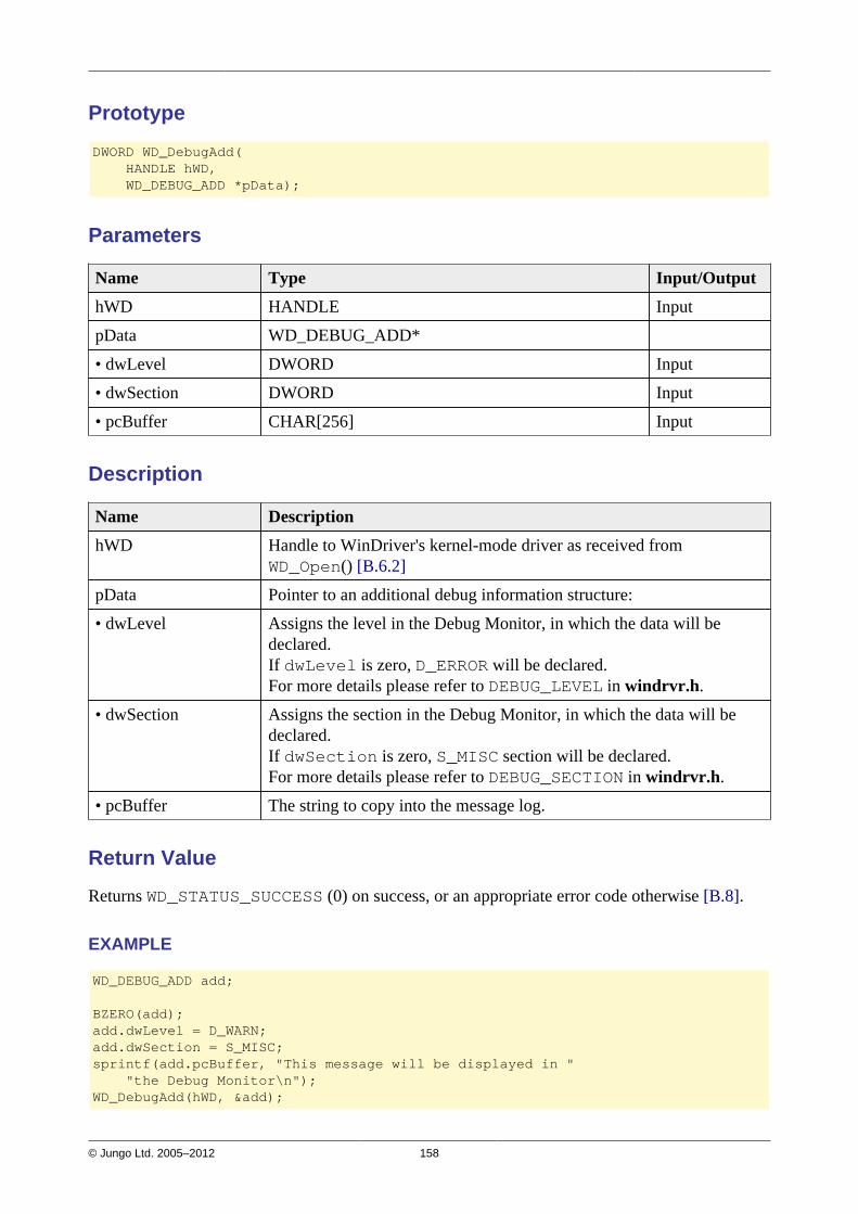
© Jungo Ltd. 2005–2012 158
Prototype
DWORD WD_DebugAdd( HANDLE hWD, WD_DEBUG_ADD *pData);
Parameters
Name Type Input/Output
hWD HANDLE Input
pData WD_DEBUG_ADD*
• dwLevel DWORD Input
• dwSection DWORD Input
• pcBuffer CHAR[256] Input
Description
Name Description
hWD Handle to WinDriver's kernel-mode driver as received fromWD_Open() [B.6.2]
pData Pointer to an additional debug information structure:
• dwLevel Assigns the level in the Debug Monitor, in which the data will bedeclared.If dwLevel is zero, D_ERROR will be declared.For more details please refer to DEBUG_LEVEL in windrvr.h.
• dwSection Assigns the section in the Debug Monitor, in which the data will bedeclared.If dwSection is zero, S_MISC section will be declared.For more details please refer to DEBUG_SECTION in windrvr.h.
• pcBuffer The string to copy into the message log.
Return Value
Returns WD_STATUS_SUCCESS (0) on success, or an appropriate error code otherwise [B.8].
EXAMPLE
WD_DEBUG_ADD add;
BZERO(add);add.dwLevel = D_WARN;add.dwSection = S_MISC;sprintf(add.pcBuffer, "This message will be displayed in " "the Debug Monitor\n");WD_DebugAdd(hWD, &add);
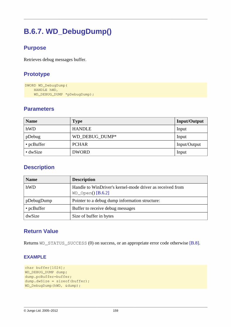
© Jungo Ltd. 2005–2012 159
B.6.7. WD_DebugDump()
Purpose
Retrieves debug messages buffer.
Prototype
DWORD WD_DebugDump( HANDLE hWD, WD_DEBUG_DUMP *pDebugDump);
Parameters
Name Type Input/Output
hWD HANDLE Input
pDebug WD_DEBUG_DUMP* Input
• pcBuffer PCHAR Input/Output
• dwSize DWORD Input
Description
Name Description
hWD Handle to WinDriver's kernel-mode driver as received fromWD_Open() [B.6.2]
pDebugDump Pointer to a debug dump information structure:
• pcBuffer Buffer to receive debug messages
dwSize Size of buffer in bytes
Return Value
Returns WD_STATUS_SUCCESS (0) on success, or an appropriate error code otherwise [B.8].
EXAMPLE
char buffer[1024];WD_DEBUG_DUMP dump;dump.pcBuffer=buffer;dump.dwSize = sizeof(buffer);WD_DebugDump(hWD, &dump);
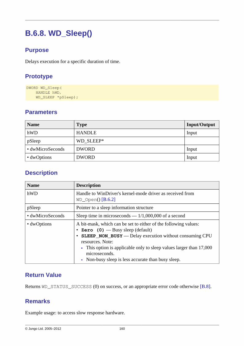
© Jungo Ltd. 2005–2012 160
B.6.8. WD_Sleep()
Purpose
Delays execution for a specific duration of time.
Prototype
DWORD WD_Sleep( HANDLE hWD, WD_SLEEP *pSleep);
Parameters
Name Type Input/Output
hWD HANDLE Input
pSleep WD_SLEEP*
• dwMicroSeconds DWORD Input
• dwOptions DWORD Input
Description
Name Description
hWD Handle to WinDriver's kernel-mode driver as received fromWD_Open() [B.6.2]
pSleep Pointer to a sleep information structure
• dwMicroSeconds Sleep time in microseconds — 1/1,000,000 of a second
• dwOptions A bit-mask, which can be set to either of the following values:• Zero (0) — Busy sleep (default)• SLEEP_NON_BUSY — Delay execution without consuming CPU
resources. Note:This option is applicable only to sleep values larger than 17,000microseconds.Non-busy sleep is less accurate than busy sleep.
Return Value
Returns WD_STATUS_SUCCESS (0) on success, or an appropriate error code otherwise [B.8].
Remarks
Example usage: to access slow response hardware.

© Jungo Ltd. 2005–2012 161
EXAMPLE
WD_Sleep slp;
BZERO(slp);slp.dwMicroSeconds = 200;WD_Sleep(hWD, &slp);
B.6.9. WD_License()
Purpose
Transfers the license string to the WinDriver kernel module and returns information regarding thelicense type of the specified license string.
When using the WDU USB APIs [B.2] your WinDriver license registration is done via thecall to WDU_Init() [B.4.1], so you do not need to call WD_License() directly from yourcode.
Prototype
DWORD WD_License( HANDLE hWD, WD_LICENSE *pLicense);
Parameters
Name Type Input/Output
hWD HANDLE Input
pLicense WD_LICENSE*
• cLicense CHAR[] Input
• dwLicense DWORD Output
• dwLicense2 DWORD Output
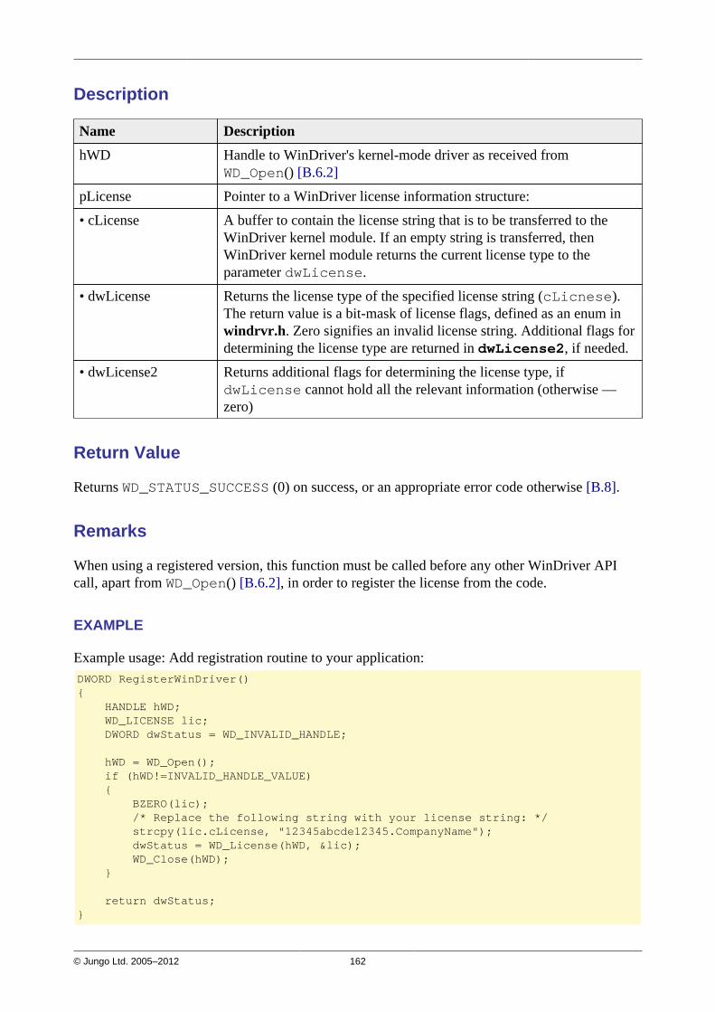
© Jungo Ltd. 2005–2012 162
Description
Name Description
hWD Handle to WinDriver's kernel-mode driver as received fromWD_Open() [B.6.2]
pLicense Pointer to a WinDriver license information structure:
• cLicense A buffer to contain the license string that is to be transferred to theWinDriver kernel module. If an empty string is transferred, thenWinDriver kernel module returns the current license type to theparameter dwLicense.
• dwLicense Returns the license type of the specified license string (cLicnese).The return value is a bit-mask of license flags, defined as an enum inwindrvr.h. Zero signifies an invalid license string. Additional flags fordetermining the license type are returned in dwLicense2, if needed.
• dwLicense2 Returns additional flags for determining the license type, ifdwLicense cannot hold all the relevant information (otherwise —zero)
Return Value
Returns WD_STATUS_SUCCESS (0) on success, or an appropriate error code otherwise [B.8].
Remarks
When using a registered version, this function must be called before any other WinDriver APIcall, apart from WD_Open() [B.6.2], in order to register the license from the code.
EXAMPLE
Example usage: Add registration routine to your application:DWORD RegisterWinDriver(){ HANDLE hWD; WD_LICENSE lic; DWORD dwStatus = WD_INVALID_HANDLE;
hWD = WD_Open(); if (hWD!=INVALID_HANDLE_VALUE) { BZERO(lic); /* Replace the following string with your license string: */ strcpy(lic.cLicense, "12345abcde12345.CompanyName"); dwStatus = WD_License(hWD, &lic); WD_Close(hWD); }
return dwStatus;}

© Jungo Ltd. 2005–2012 163
B.7. User-Mode Utility FunctionsThis section describes a number of user-mode utility functions you will find useful forimplementing various tasks. These utility functions are multi-platform, implemented on alloperating systems supported by WinDriver.
B.7.1. Stat2Str
Purpose
Retrieves the status string that corresponds to a status code.
Prototype
const char *Stat2Str(DWORD dwStatus);
Parameters
Name Type Input/Output
dwStatus DWORD Input
Description
Name Description
• dwStatus A numeric status code
Return Value
Returns the verbal status description (string) that corresponds to the specified numeric status code.
Remarks
See Section B.8 for a complete list of status codes and strings.

© Jungo Ltd. 2005–2012 164
B.7.2. get_os_type
Purpose
Retrieves the type of the operating system.
Prototype
OS_TYPE get_os_type(void);
Return Value
Returns the type of the operating system.If the operating system type is not detected, returns OS_CAN_NOT_DETECT.
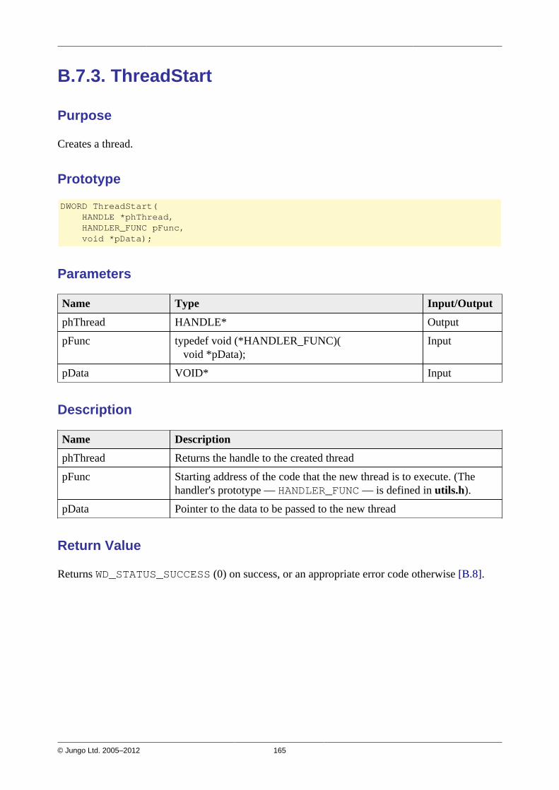
© Jungo Ltd. 2005–2012 165
B.7.3. ThreadStart
Purpose
Creates a thread.
Prototype
DWORD ThreadStart( HANDLE *phThread, HANDLER_FUNC pFunc, void *pData);
Parameters
Name Type Input/Output
phThread HANDLE* Output
pFunc typedef void (*HANDLER_FUNC)( void *pData);
Input
pData VOID* Input
Description
Name Description
phThread Returns the handle to the created thread
pFunc Starting address of the code that the new thread is to execute. (Thehandler's prototype — HANDLER_FUNC — is defined in utils.h).
pData Pointer to the data to be passed to the new thread
Return Value
Returns WD_STATUS_SUCCESS (0) on success, or an appropriate error code otherwise [B.8].

© Jungo Ltd. 2005–2012 166
B.7.4. ThreadWait
Purpose
Waits for a thread to exit.
Prototype
void ThreadWait(HANDLE hThread);
Parameters
Name Type Input/Output
hThread HANDLE Input
Description
Name Description
hThread The handle to the thread whose completion is awaited
Return Value
None

© Jungo Ltd. 2005–2012 167
B.7.5. OsEventCreate
Purpose
Creates an event object.
Prototype
DWORD OsEventCreate(HANDLE *phOsEvent);
Parameters
Name Type Input/Output
phOsEvent HANDLE* Output
Description
Name Description
phOsEvent The pointer to a variable that receives a handle to the newly createdevent object
Return Value
Returns WD_STATUS_SUCCESS (0) on success, or an appropriate error code otherwise [B.8].
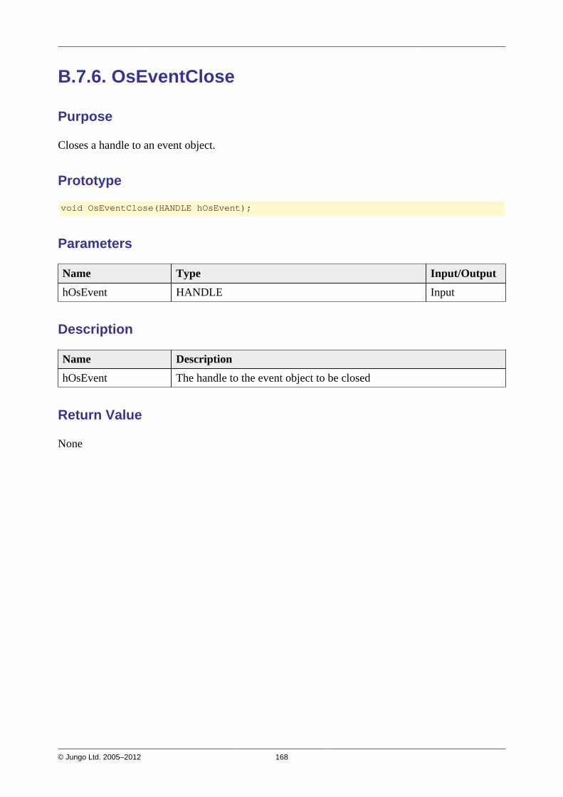
© Jungo Ltd. 2005–2012 168
B.7.6. OsEventClose
Purpose
Closes a handle to an event object.
Prototype
void OsEventClose(HANDLE hOsEvent);
Parameters
Name Type Input/Output
hOsEvent HANDLE Input
Description
Name Description
hOsEvent The handle to the event object to be closed
Return Value
None

© Jungo Ltd. 2005–2012 169
B.7.7. OsEventWait
Purpose
Waits until a specified event object is in the signaled state or the time-out interval elapses.
Prototype
DWORD OsEventWait( HANDLE hOsEvent, DWORD dwSecTimeout);
Parameters
Name Type Input/Output
hOsEvent HANDLE Input
dwSecTimeout DWORD Input
Description
Name Description
hOsEvent The handle to the event object
dwSecTimeout Time-out interval of the event, in seconds.For an infinite wait, set the timeout to INFINITE.
Return Value
Returns WD_STATUS_SUCCESS (0) on success, or an appropriate error code otherwise [B.8].
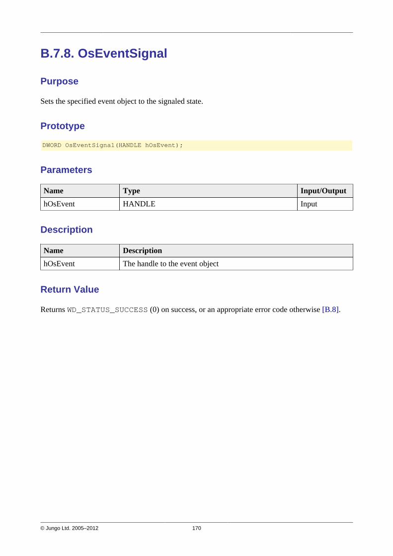
© Jungo Ltd. 2005–2012 170
B.7.8. OsEventSignal
Purpose
Sets the specified event object to the signaled state.
Prototype
DWORD OsEventSignal(HANDLE hOsEvent);
Parameters
Name Type Input/Output
hOsEvent HANDLE Input
Description
Name Description
hOsEvent The handle to the event object
Return Value
Returns WD_STATUS_SUCCESS (0) on success, or an appropriate error code otherwise [B.8].

© Jungo Ltd. 2005–2012 171
B.7.9. OsEventReset
Purpose
Resets the specified event object to the non-signaled state.
Prototype
DWORD OsEventReset(HANDLE hOsEvent);
Parameters
Name Type Input/Output
hOsEvent HANDLE Input
Description
Name Description
hOsEvent The handle to the event object
Return Value
Returns WD_STATUS_SUCCESS (0) on success, or an appropriate error code otherwise [B.8].

© Jungo Ltd. 2005–2012 172
B.7.10. OsMutexCreate
Purpose
Creates a mutex object.
Prototype
DWORD OsMutexCreate(HANDLE *phOsMutex);
Parameters
Name Type Input/Output
phOsMutex HANDLE* Output
Description
Name Description
phOsMutex The pointer to a variable that receives a handle to the newly createdmutex object
Return Value
Returns WD_STATUS_SUCCESS (0) on success, or an appropriate error code otherwise [B.8].

© Jungo Ltd. 2005–2012 173
B.7.11. OsMutexClose
Purpose
Closes a handle to a mutex object.
Prototype
void OsMutexClose(HANDLE hOsMutex);
Parameters
Name Type Input/Output
hOsMutex HANDLE Input
Description
Name Description
hOsMutex The handle to the mutex object to be closed
Return Value
None

© Jungo Ltd. 2005–2012 174
B.7.12. OsMutexLock
Purpose
Locks the specified mutex object.
Prototype
DWORD OsMutexLock(HANDLE hOsMutex);
Parameters
Name Type Input/Output
hOsMutex HANDLE Input
Description
Name Description
hOsMutex The handle to the mutex object to be locked
Return Value
Returns WD_STATUS_SUCCESS (0) on success, or an appropriate error code otherwise [B.8].

© Jungo Ltd. 2005–2012 175
B.7.13. OsMutexUnlock
Purpose
Releases (unlocks) a locked mutex object.
Prototype
DWORD OsMutexUnlock(HANDLE hOsMutex);
Parameters
Name Type Input/Output
hOsMutex HANDLE Input
Description
Name Description
hOsMutex The handle to the mutex object to be unlocked
Return Value
Returns WD_STATUS_SUCCESS (0) on success, or an appropriate error code otherwise [B.8].
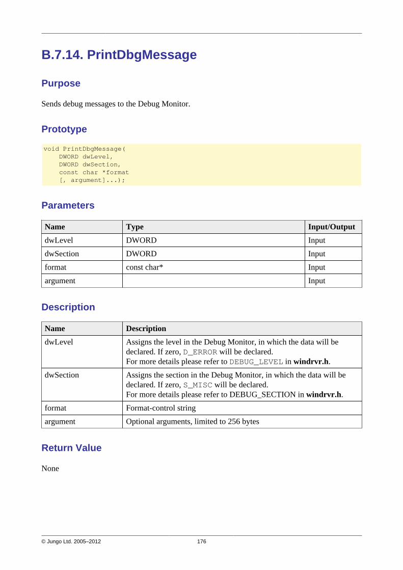
© Jungo Ltd. 2005–2012 176
B.7.14. PrintDbgMessage
Purpose
Sends debug messages to the Debug Monitor.
Prototype
void PrintDbgMessage( DWORD dwLevel, DWORD dwSection, const char *format [, argument]...);
Parameters
Name Type Input/Output
dwLevel DWORD Input
dwSection DWORD Input
format const char* Input
argument Input
Description
Name Description
dwLevel Assigns the level in the Debug Monitor, in which the data will bedeclared. If zero, D_ERROR will be declared.For more details please refer to DEBUG_LEVEL in windrvr.h.
dwSection Assigns the section in the Debug Monitor, in which the data will bedeclared. If zero, S_MISC will be declared.For more details please refer to DEBUG_SECTION in windrvr.h.
format Format-control string
argument Optional arguments, limited to 256 bytes
Return Value
None

© Jungo Ltd. 2005–2012 177
B.7.15. WD_LogStart
Purpose
Opens a log file.
Prototype
DWORD WD_LogStart( const char *sFileName, const char *sMode);
Parameters
Name Type Input/Output
sFileName const char* Input
sMode const char* Input
Description
Name Description
sFileName Name of log file to be opened
sMode Type of access permitted.For example, NULL or w opens an empty file for writing, and if thegiven file exists, its contents are destroyed;a opens a file for writing at the end of the file (i.e., append).
Return Value
Returns WD_STATUS_SUCCESS (0) on success, or an appropriate error code otherwise [B.8].
Remarks
Once a log file is opened, all API calls are logged in this file.You may add your own printouts to the log file by calling WD_LogAdd() [B.7.17].
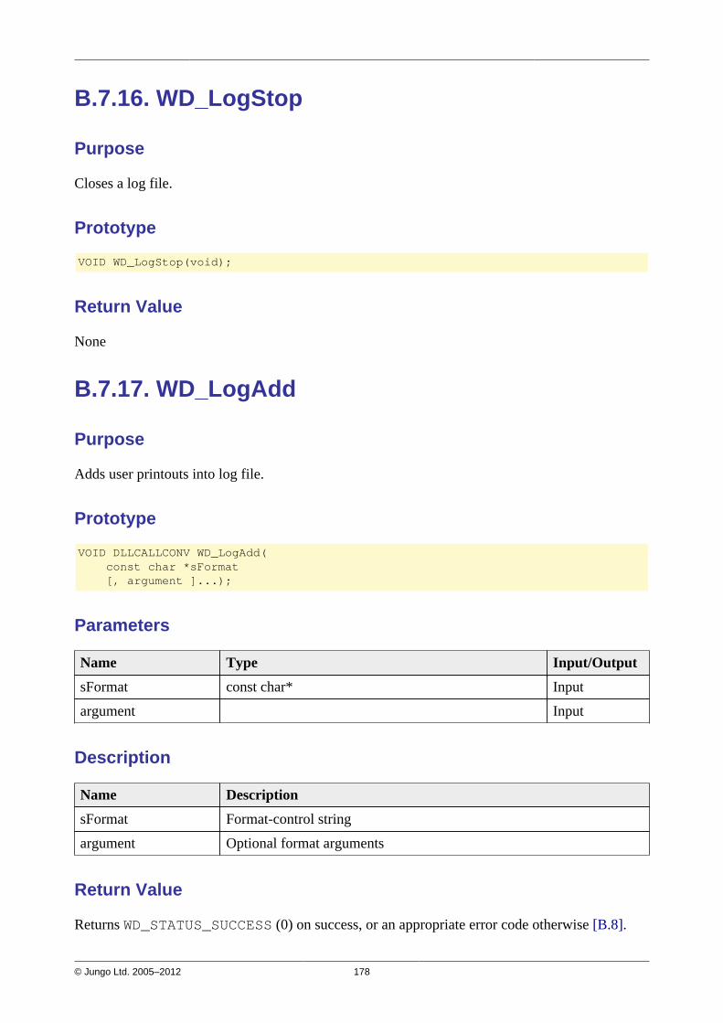
© Jungo Ltd. 2005–2012 178
B.7.16. WD_LogStop
Purpose
Closes a log file.
Prototype
VOID WD_LogStop(void);
Return Value
None
B.7.17. WD_LogAdd
Purpose
Adds user printouts into log file.
Prototype
VOID DLLCALLCONV WD_LogAdd( const char *sFormat [, argument ]...);
Parameters
Name Type Input/Output
sFormat const char* Input
argument Input
Description
Name Description
sFormat Format-control string
argument Optional format arguments
Return Value
Returns WD_STATUS_SUCCESS (0) on success, or an appropriate error code otherwise [B.8].
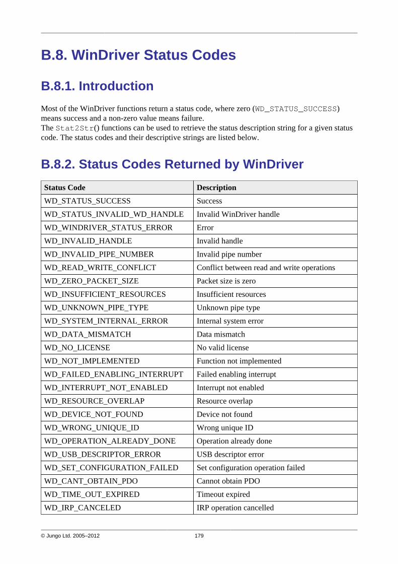
© Jungo Ltd. 2005–2012 179
B.8. WinDriver Status Codes
B.8.1. Introduction
Most of the WinDriver functions return a status code, where zero (WD_STATUS_SUCCESS)means success and a non-zero value means failure.The Stat2Str() functions can be used to retrieve the status description string for a given statuscode. The status codes and their descriptive strings are listed below.
B.8.2. Status Codes Returned by WinDriver
Status Code Description
WD_STATUS_SUCCESS Success
WD_STATUS_INVALID_WD_HANDLE Invalid WinDriver handle
WD_WINDRIVER_STATUS_ERROR Error
WD_INVALID_HANDLE Invalid handle
WD_INVALID_PIPE_NUMBER Invalid pipe number
WD_READ_WRITE_CONFLICT Conflict between read and write operations
WD_ZERO_PACKET_SIZE Packet size is zero
WD_INSUFFICIENT_RESOURCES Insufficient resources
WD_UNKNOWN_PIPE_TYPE Unknown pipe type
WD_SYSTEM_INTERNAL_ERROR Internal system error
WD_DATA_MISMATCH Data mismatch
WD_NO_LICENSE No valid license
WD_NOT_IMPLEMENTED Function not implemented
WD_FAILED_ENABLING_INTERRUPT Failed enabling interrupt
WD_INTERRUPT_NOT_ENABLED Interrupt not enabled
WD_RESOURCE_OVERLAP Resource overlap
WD_DEVICE_NOT_FOUND Device not found
WD_WRONG_UNIQUE_ID Wrong unique ID
WD_OPERATION_ALREADY_DONE Operation already done
WD_USB_DESCRIPTOR_ERROR USB descriptor error
WD_SET_CONFIGURATION_FAILED Set configuration operation failed
WD_CANT_OBTAIN_PDO Cannot obtain PDO
WD_TIME_OUT_EXPIRED Timeout expired
WD_IRP_CANCELED IRP operation cancelled

© Jungo Ltd. 2005–2012 180
Status Code Description
WD_FAILED_USER_MAPPING Failed to map in user space
WD_FAILED_KERNEL_MAPPING Failed to map in kernel space
WD_NO_RESOURCES_ON_DEVICE No resources on the device
WD_NO_EVENTS No events
WD_INVALID_PARAMETER Invalid parameter
WD_INCORRECT_VERSION Incorrect WinDriver version installed
WD_TRY_AGAIN Try again
WD_INVALID_IOCTL Received an invalid IOCTL
WD_OPERATION_FAILED Operation failed
WD_INVALID_32BIT_APP Received an invalid 32-bit IOCTL
WD_TOO_MANY_HANDLES No room to add handle
WD_NO_DEVICE_OBJECT Driver not installed
B.8.3. Status Codes Returned by USBD
The following WinDriver status codes comply with USBD_XXX status codes returned by theUSB stack drivers.
Status Code Description
USBD Status Types
WD_USBD_STATUS_SUCCESS USBD: Success
WD_USBD_STATUS_PENDING USBD: Operation pending
WD_USBD_STATUS_ERROR USBD: Error
WD_USBD_STATUS_HALTED USBD: Halted
USBD Status Codes(NOTE: The status codes consist of one of the status types above and an error code, i.e.,0xXYYYYYYYL, where X=status type and YYYYYYY=error code. The same error codesmay also appear with one of the other status types as well.)
HC (Host Controller) Status Codes(NOTE: These use the WD_USBD_STATUS_HALTED status type.)
WD_USBD_STATUS_CRC HC status: CRC
WD_USBD_STATUS_BTSTUFF HC status: Bit stuffing
WD_USBD_STATUS_DATA_TOGGLE_MISMATCH HC status: Data toggle mismatch
WD_USBD_STATUS_STALL_PID HC status: PID stall
WD_USBD_STATUS_DEV_NOT_RESPONDING HC status: Device not responding
WD_USBD_STATUS_PID_CHECK_FAILURE HC status: PID check failed
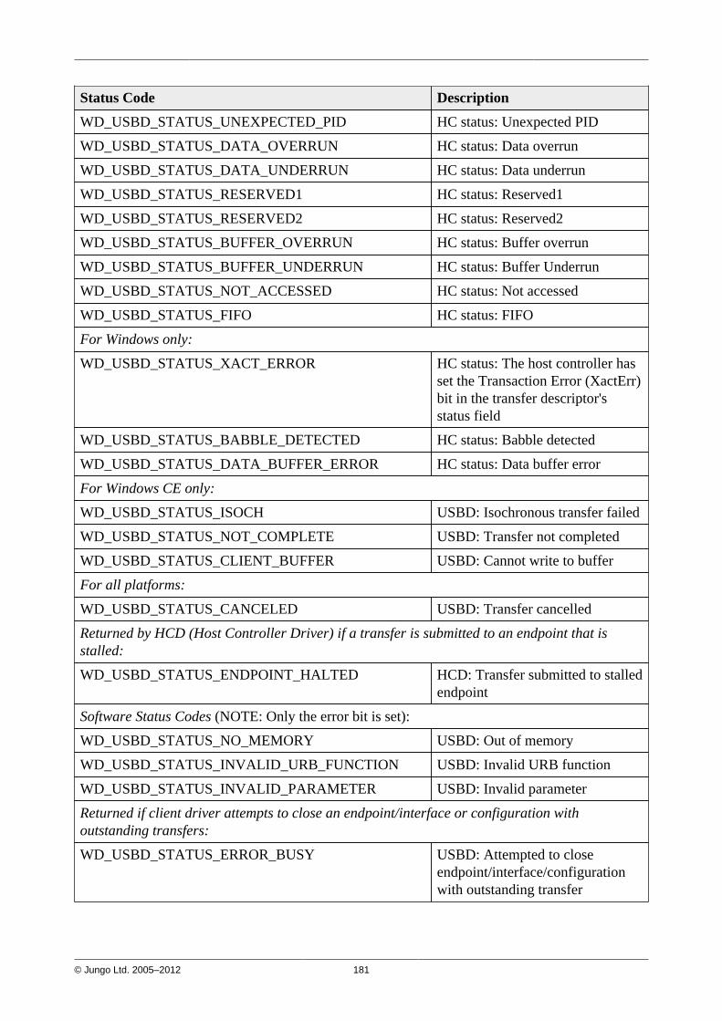
© Jungo Ltd. 2005–2012 181
Status Code Description
WD_USBD_STATUS_UNEXPECTED_PID HC status: Unexpected PID
WD_USBD_STATUS_DATA_OVERRUN HC status: Data overrun
WD_USBD_STATUS_DATA_UNDERRUN HC status: Data underrun
WD_USBD_STATUS_RESERVED1 HC status: Reserved1
WD_USBD_STATUS_RESERVED2 HC status: Reserved2
WD_USBD_STATUS_BUFFER_OVERRUN HC status: Buffer overrun
WD_USBD_STATUS_BUFFER_UNDERRUN HC status: Buffer Underrun
WD_USBD_STATUS_NOT_ACCESSED HC status: Not accessed
WD_USBD_STATUS_FIFO HC status: FIFO
For Windows only:
WD_USBD_STATUS_XACT_ERROR HC status: The host controller hasset the Transaction Error (XactErr)bit in the transfer descriptor'sstatus field
WD_USBD_STATUS_BABBLE_DETECTED HC status: Babble detected
WD_USBD_STATUS_DATA_BUFFER_ERROR HC status: Data buffer error
For Windows CE only:
WD_USBD_STATUS_ISOCH USBD: Isochronous transfer failed
WD_USBD_STATUS_NOT_COMPLETE USBD: Transfer not completed
WD_USBD_STATUS_CLIENT_BUFFER USBD: Cannot write to buffer
For all platforms:
WD_USBD_STATUS_CANCELED USBD: Transfer cancelled
Returned by HCD (Host Controller Driver) if a transfer is submitted to an endpoint that isstalled:
WD_USBD_STATUS_ENDPOINT_HALTED HCD: Transfer submitted to stalledendpoint
Software Status Codes (NOTE: Only the error bit is set):
WD_USBD_STATUS_NO_MEMORY USBD: Out of memory
WD_USBD_STATUS_INVALID_URB_FUNCTION USBD: Invalid URB function
WD_USBD_STATUS_INVALID_PARAMETER USBD: Invalid parameter
Returned if client driver attempts to close an endpoint/interface or configuration withoutstanding transfers:
WD_USBD_STATUS_ERROR_BUSY USBD: Attempted to closeendpoint/interface/configurationwith outstanding transfer
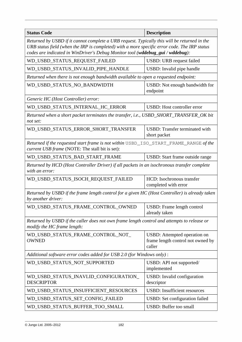
© Jungo Ltd. 2005–2012 182
Status Code Description
Returned by USBD if it cannot complete a URB request. Typically this will be returned in theURB status field (when the IRP is completed) with a more specific error code. The IRP statuscodes are indicated in WinDriver's Debug Monitor tool (wddebug_gui / wddebug):
WD_USBD_STATUS_REQUEST_FAILED USBD: URB request failed
WD_USBD_STATUS_INVALID_PIPE_HANDLE USBD: Invalid pipe handle
Returned when there is not enough bandwidth available to open a requested endpoint:
WD_USBD_STATUS_NO_BANDWIDTH USBD: Not enough bandwidth forendpoint
Generic HC (Host Controller) error:
WD_USBD_STATUS_INTERNAL_HC_ERROR USBD: Host controller error
Returned when a short packet terminates the transfer, i.e., USBD_SHORT_TRANSFER_OK bitnot set:
WD_USBD_STATUS_ERROR_SHORT_TRANSFER USBD: Transfer terminated withshort packet
Returned if the requested start frame is not within USBD_ISO_START_FRAME_RANGE of thecurrent USB frame (NOTE: The stall bit is set):
WD_USBD_STATUS_BAD_START_FRAME USBD: Start frame outside range
Returned by HCD (Host Controller Driver) if all packets in an isochronous transfer completewith an error:
WD_USBD_STATUS_ISOCH_REQUEST_FAILED HCD: Isochronous transfercompleted with error
Returned by USBD if the frame length control for a given HC (Host Controller) is already takenby another driver:
WD_USBD_STATUS_FRAME_CONTROL_OWNED USBD: Frame length controlalready taken
Returned by USBD if the caller does not own frame length control and attempts to release ormodify the HC frame length:
WD_USBD_STATUS_FRAME_CONTROL_NOT_OWNED
USBD: Attempted operation onframe length control not owned bycaller
Additional software error codes added for USB 2.0 (for Windows only) :
WD_USBD_STATUS_NOT_SUPPORTED USBD: API not supported/implemented
WD_USBD_STATUS_INAVLID_CONFIGURATION_DESCRIPTOR
USBD: Invalid configurationdescriptor
WD_USBD_STATUS_INSUFFICIENT_RESOURCES USBD: Insufficient resources
WD_USBD_STATUS_SET_CONFIG_FAILED USBD: Set configuration failed
WD_USBD_STATUS_BUFFER_TOO_SMALL USBD: Buffer too small
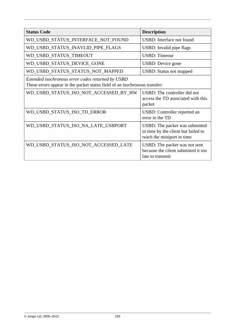
© Jungo Ltd. 2005–2012 183
Status Code Description
WD_USBD_STATUS_INTERFACE_NOT_FOUND USBD: Interface not found
WD_USBD_STATUS_INAVLID_PIPE_FLAGS USBD: Invalid pipe flags
WD_USBD_STATUS_TIMEOUT USBD: Timeout
WD_USBD_STATUS_DEVICE_GONE USBD: Device gone
WD_USBD_STATUS_STATUS_NOT_MAPPED USBD: Status not mapped
Extended isochronous error codes returned by USBDThese errors appear in the packet status field of an isochronous transfer:
WD_USBD_STATUS_ISO_NOT_ACCESSED_BY_HW USBD: The controller did notaccess the TD associated with thispacket
WD_USBD_STATUS_ISO_TD_ERROR USBD: Controller reported anerror in the TD
WD_USBD_STATUS_ISO_NA_LATE_USBPORT USBD: The packet was submittedin time by the client but failed toreach the miniport in time
WD_USBD_STATUS_ISO_NOT_ACCESSED_LATE USBD: The packet was not sentbecause the client submitted it toolate to transmit

© Jungo Ltd. 2005–2012 184
Appendix CTroubleshooting and SupportPlease refer to http://www.jungo.com/st/support/support_windriver.html for additional resourcesfor developers, including:
• Technical documents
• FAQs
• Samples
• Quick start guides
© Jungo Ltd. 2005–2012 185
Appendix DEvaluation Version Limitations
D.1. Windows WinDriver EvaluationLimitations• Each time WinDriver is activated, an Unregistered message appears.
• When using DriverWizard, a dialogue box with a message stating that an evaluation version isbeing run appears on every interaction with the hardware.
• DriverWizard [5]:
• Each time DriverWizard is activated, an Unregistered message appears.
• An evaluation message is displayed on every interaction with the hardware usingDriverWizard.
• WinDriver will function for only 30 days after the original installation.
D.2. Windows CE WinDriver EvaluationLimitations• Each time WinDriver is activated, an Unregistered message appears.
• The WinDriver CE Kernel (windrvr6.dll) will operate for no more than 60 minutes at a time.
• DriverWizard [5] (used on a host Windows PC) —
• Each time DriverWizard is activated, an Unregistered message appears.
• An evaluation message is displayed on every interaction with the hardware usingDriverWizard.
© Jungo Ltd. 2005–2012 186
D.3. Linux WinDriver Evaluation Limitations• Each time WinDriver is activated, an Unregistered message appears.
• DriverWizard [5]:
• Each time DriverWizard is activated, an Unregistered message appears.
• An evaluation message is displayed on every interaction with the hardware usingDriverWizard.
• WinDriver's kernel module will work for no more than 60 minutes at a time. To continueworking, the WinDriver kernel module must be reloaded (unload and load the module) usingthe following commands:
The following commands must be executed with root privileges.
To unload —# /sbin/modprobe -r windrvr6
To load —# <path to wdreg> windrvr6
wdreg is provided in the WinDriver/util directory.

© Jungo Ltd. 2005–2012 187
Appendix EPurchasing WinDriverFill in the order form found in Start | WinDriver | Order Form on your Windows start menu,and send it to Jungo via email, fax or mail (see details below).
Your WinDriver package will be sent to you via courier or registered mail. The WinDriver licensestring will be emailed to you immediately.
Email Web Site
Sales / Information: [email protected] http://www.jungo.com
License Registration: [email protected]
Phone Fax
Worldwide: +972 74 721 2121 Worldwide: +972 74 721 2122
USA (toll free): +1 877 514 0537 USA (toll free): +1 877 514 0538
Mailing Address
Jungo Ltd.1 Hamachshev St.P.O. Box 8493Netanya 42504Israel

© Jungo Ltd. 2005–2012 188
Appendix FDistributing Your Driver — LegalIssuesWinDriver is licensed per-seat. The WinDriver license allows one developer on a single computerto develop an unlimited number of device drivers, and to freely distribute the created driverswithout royalties, as outlined in the license agreement in the WinDriver/docs/license.pdf file.

© Jungo Ltd. 2005–2012 189
Appendix GAdditional DocumentationUpdated Manuals
The most updated WinDriver user manuals can be found on Jungo's site at:http://www.jungo.com/st/support/support_windriver.html.
Version History
If you wish to view WinDriver version history, refer to the WinDriver Release Notes: http://www.jungo.com/st/wdver.html. The release notes include a list of the new features, enhancementsand fixes that have been added in each WinDriver version.
Technical Documents
For additional information, refer to the WinDriver Technical Documents database:http://www.jungo.com/st/support/tech_docs_indexes/main_index.html.This database includes detailed descriptions of WinDriver's features, utilities and APIs and theircorrect usage, troubleshooting of common problems, useful tips and answers to frequently askedquestions.


![WinDriver v10.10 USB リファレンス - XLsoft.comjp.xlsoft.com/documents/windriver/WD1010J_USB_Ref.pdfWDU_DETACH_CALLBACK [A.2.2]、および WDU_POWER_CHANGE_CALLBACK [A.2.3])](https://img.pdfslide.us/doc/110x75/611c9441c33ba048057c4f1e/windriver-v1010-usb-ffff-wdudetachcallback-a22.jpg)