Embed Size (px)
Citation preview
CI/SfB Xt6
March 2018
BS EN 845-3 BS EN 1090-1
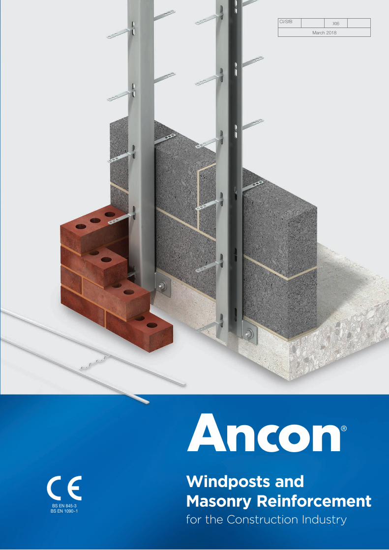
Windposts and Masonry Reinforcementfor the Construction Industry
Masonry Reinforcement Strengthening Masonry Panels
AMR Masonry Reinforcement 4
AMR-X Masonry Reinforcement 5
Reinforcing Stack-Bonded Masonry 6
Reinforcement for Collar-Jointed Walls 6
Windposts 7
Parapet Posts 7
Windpost Types 8
Windpost Ties 8
Fixings & Connections 9
Properties & Recommended Loads 10-11
Contents
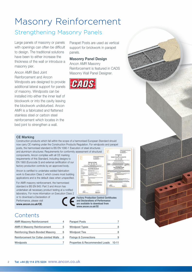
Parapet Posts are used as vertical support for brickwork in parapet panels.
Masonry Panel DesignAncon AMR Masonry Reinforcement is featured in CADS Masonry Wall Panel Designer.
2 Tel: +44 (0) 114 275 5224 www.ancon.co.uk
CE MarkingConstruction products which fall within the scope of a harmonised European Standard should now carry CE marking under the Construction Products Regulation. For windposts and parapet posts, the harmonised standard is BS EN 1090-1 Execution of steel structures and aluminium structures: Requirements for conformity assessment of structural components. Ancon complies with all CE marking requirements of this Standard, including designs to EN 1993 (Eurocode 3) and external certification of our factory production controls by an approved body.
Ancon is certified to undertake welded fabrication work to Execution Class 2 which covers most building applications and is the default class when unspecified.
For AMR masonry reinforcement, the harmonised standard is BS EN 845: Part 3 and Ancon has undertaken all necessary product testing at a notified laboratory. For more information on Execution Class 2 or to download a Declaration of Performance, please visit www.ancon.co.uk/CE.
and aluminium structures: Requirements for conformity assessment of structural
Factory Production Control Certificates and Declarations of Performance are available to download from www.ancon.co.uk/CE
Large panels of masonry or panels with openings can often be difficult to design. The traditional solutions have been to either increase the thickness of the wall or introduce a masonry pier.
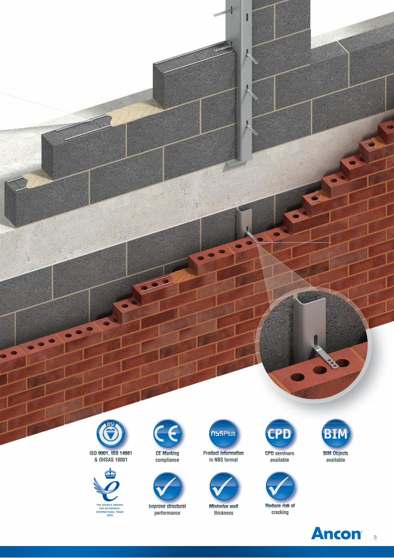
Ancon AMR Bed Joint Reinforcement and Ancon Windposts are designed to provide additional lateral support for panels of masonry. Windposts can be installed into either the inner leaf of blockwork or into the cavity leaving the blockwork undisturbed. Ancon AMR is a fabricated and flattened stainless steel or carbon steel reinforcement which locates in the bed joint to strengthen a wall.
CPD seminars available
CPD seminars
Reduce risk ofcracking
Reduce risk of
3
Minimise wall thickness
Minimise wall Improve structural performance
Improve structural
BIM Objects available
BIM ObjectsProduct information in NBS format
Product information CE Marking complianceCE Marking ISO 9001, ISO 14001
& OHSAS 18001ISO 9001, ISO 14001
175mm
150mm
100mm
60mm
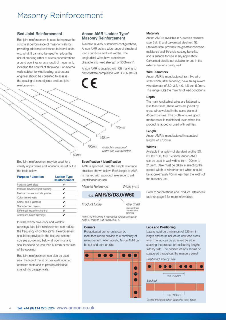
Available in a range of widths and wire diameters
Ancon AMR ‘Ladder Type’ Masonry ReinforcementAvailable in various standard configurations, Ancon AMR suits a wide range of structural load conditions and wall widths. The longitudinal wires have a minimum characteristic yield strength of 500N/mm2.
Ancon AMR is supplied with CE marking to demonstrate compliance with BS EN 845-3.
4 Tel: +44 (0) 114 275 5224 www.ancon.co.uk
Masonry Reinforcement
In walls which have door and window openings, bed joint reinforcement can reduce the frequency of control joints. Reinforcement should be provided in the first and second courses above and below all openings and should extend no less than 600mm either side of the opening.
Bed joint reinforcement can also be used near the top of the structural walls abutting concrete roofs and to provide additional strength to parapet walls.
Bed joint reinforcement may be used for a variety of purposes and locations, as set out in the table below.
Specification / Identification AMR is specified using the simple reference structure shown below. Each length of AMR is marked with a product reference to aid identification on site.
Material Reference Width (mm)
e.g. AMR/S/D3.0/W60
Product Code Wire (mm)Equivalent wire diameter after flattening
CornersPrefabricated corner units can be manufactured to provide true continuity of reinforcement. Alternatively, Ancon AMR can be cut and bent on site.
Laps and PositioningLaps should be a minimum of 225mm in length and must include at least one cross wire. The lap can be achieved by either stacking the product or positioning lengths side by side. The position of laps should be staggered throughout the masonry panel.
min. 225mm
min. 225mm
Positioned side by side
Stacked
Overall thickness when lapped is max. 6mm
Materials Ancon AMR is available in Austenitic stainless steel (ref. S) and galvanised steel (ref. G). Stainless steel provides the greatest corrosion resistance and life-cycle costing benefits, and is suitable for use in any application. Galvanised steel is not suitable for use in the external leaf of a cavity wall.
Wire Diameters Ancon AMR is manufactured from five wire sizes which, after flattening, have an equivalent wire diameter of 3.0, 3.5, 4.0, 4.5 and 5.0mm. This range suits the majority of load conditions.
Depth The main longitudinal wires are flattened to less than 3mm. These wires are joined by cross wires welded in the same plane at 450mm centres. This profile ensures good mortar cover is maintained, even when the product is lapped or used with wall ties.
Length Ancon AMR is manufactured in standard lengths of 2700mm.
Widths Available in a variety of standard widths (50, 60, 80, 100, 150, 175mm), Ancon AMR can be used in wall widths from 100mm to 215mm. Care must be taken in selecting the correct width of reinforcement which should be approximately 40mm less than the width of the masonry unit.
Refer to ‘Applications and Product References’ table on page 5 for more information.
Purpose / Location Ladder Type ReinforcementIncrease panel sizes ✔
Increase movement joint spacing ✔
Feature courses, corbels, plinths ✔
Collar-jointed walls ✔
Corner and T junctions ✔
Stack-bonded panels ✔
Differential movement control ✔
Above and below openings ✔Note: For the AMR-X enhanced system shown on page 5, replace AMR with AMR-X.
Bed Joint ReinforcementBed joint reinforcement is used to improve the structural performance of masonry walls by providing additional resistance to lateral loads e.g. wind. It can also be used to reduce the risk of cracking either at stress concentrations around openings or as a result of movement, including the control of shrinkage. For external walls subject to wind loading, a structural engineer should be consulted to assess the spacing of control joints and bed joint reinforcement.
5
AMR and AMR-X Typical Applications
Wall Product Thickness Reference AMR/S/D3.0/W60 *AMR-X/S/D3.0/W60
102mm Brick/ AMR/S/D3.5/W60 100mm or 125mm Block AMR/S/D4.0/W60 AMR/S/D4.5/W60 AMR/S/D5.0/W60 *AMR-X/S/D5.0/W60
AMR/S/D3.0/W100 *AMR-X/S/D3.0/W100 AMR/S/D3.5/W100 140mm or 150mm Block AMR/S/D4.0/W100 AMR/S/D4.5/W100 AMR/S/D5.0/W100 *AMR-X/S/D5.0/W100
AMR/S/D3.0/W150 AMR/S/D3.5/W150 190mm or 200mm Block AMR/S/D4.0/W150 AMR/S/D4.5/W150 AMR/S/D5.0/W150
AMR/S/D3.0/W175 AMR/S/D3.5/W175 215mm Block AMR/S/D4.0/W175 AMR/S/D4.5/W175 AMR/S/D5.0/W175
Note: Product references shown are for stainless steel reinforcement. For galvanised steel ‘S’ should be replaced with ‘G’. 50 and 80mm widths are also available. Wire diameters of 3.5 and 4.5mm are only available in stainless steel. *AMR-X only available in stainless steel and 60mm / 100mm widths.
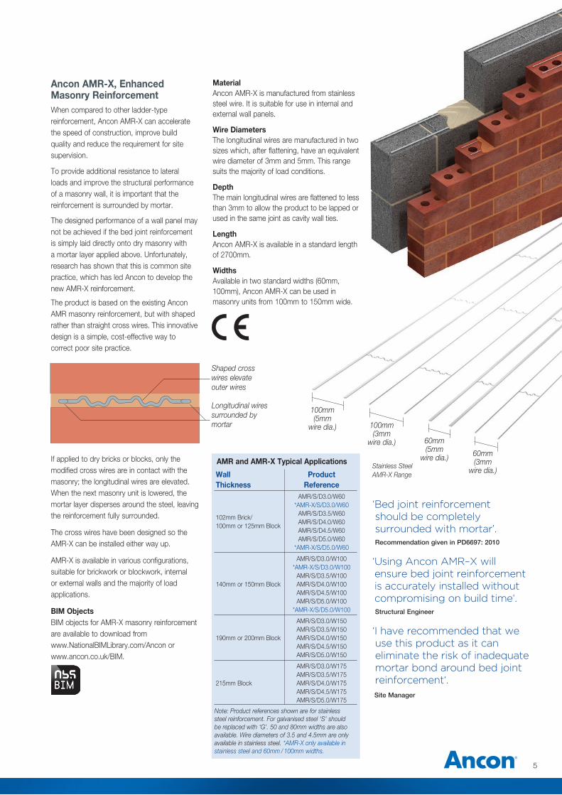
100mm (3mm
wire dia.) 60mm (5mm
wire dia.) 60mm (3mm
wire dia.)
MaterialAncon AMR-X is manufactured from stainless steel wire. It is suitable for use in internal and external wall panels.
Wire DiametersThe longitudinal wires are manufactured in two sizes which, after flattening, have an equivalent wire diameter of 3mm and 5mm. This range suits the majority of load conditions.
DepthThe main longitudinal wires are flattened to less than 3mm to allow the product to be lapped or used in the same joint as cavity wall ties.
LengthAncon AMR-X is available in a standard length of 2700mm.
WidthsAvailable in two standard widths (60mm, 100mm), Ancon AMR-X can be used in masonry units from 100mm to 150mm wide.
To provide additional resistance to lateral loads and improve the structural performance of a masonry wall, it is important that the reinforcement is surrounded by mortar.
The designed performance of a wall panel may not be achieved if the bed joint reinforcement is simply laid directly onto dry masonry with a mortar layer applied above. Unfortunately, research has shown that this is common site practice, which has led Ancon to develop the new AMR-X reinforcement.
The product is based on the existing Ancon AMR masonry reinforcement, but with shaped rather than straight cross wires. This innovative design is a simple, cost-effective way to correct poor site practice.
Shaped cross wires elevate outer wires
Longitudinal wires surrounded by mortar
Ancon AMR-X, Enhanced Masonry ReinforcementWhen compared to other ladder-type reinforcement, Ancon AMR-X can accelerate the speed of construction, improve build quality and reduce the requirement for site supervision.
‘Bed joint reinforcement should be completely surrounded with mortar’. Recommendation given in PD6697: 2010
‘ Using Ancon AMR–X will ensure bed joint reinforcement is accurately installed without compromising on build time‘. Structural Engineer
‘I have recommended that we use this product as it can eliminate the risk of inadequate mortar bond around bed joint reinforcement‘.
Site Manager
If applied to dry bricks or blocks, only the modified cross wires are in contact with the masonry; the longitudinal wires are elevated. When the next masonry unit is lowered, the mortar layer disperses around the steel, leaving the reinforcement fully surrounded.
The cross wires have been designed so the AMR-X can be installed either way up.
AMR-X is available in various configurations, suitable for brickwork or blockwork, internal or external walls and the majority of load applications.
BIM ObjectsBIM objects for AMR-X masonry reinforcement are available to download from www.NationalBIMLibrary.com/Ancon or www.ancon.co.uk/BIM.
100mm (5mm
wire dia.)
Stainless Steel AMR-X Range

Reinforcing Stack-Bonded MasonryStack bonding has a distinctive uniform bond pattern and is often detailed for its aesthetic appearance without consideration for its design limitations.
Where large format masonry units are stacked one above the other, the lack of bonding between them will greatly reduce the overall flexural strength of the panel and the ability of the wall to spread vertical loads. In stack bonded masonry, concentrated loads will be carried down to the support by the particular vertical ‘column’ of masonry under load, with little distribution to adjacent masonry.
Ancon AMR Masonry Reinforcement, located in the bed joints, will increase the panel’s flexural strength and improve the capacity to resist lateral loads and spread vertical loads.
The use of Ancon reinforcement referenced AMR/S/D3.5/W60 is normally recommended at vertical centres no greater than 300mm, usually every course or every other course depending on the height of the masonry unit.
The adjacent illustration uses a 215mm unit height. This is typical advice for stack-bonded masonry up to 125mm wide. Thicker blocks require wider reinforcement. The addition of masonry reinforcement will also help with crack control.
Stainless Steel Galvanised Steel AMR-CJ / S / D3.0 / W175 AMR-CJ / G / D3.0 / W175
AMR-CJ / S / D3.5 / W175 –
AMR-CJ / S / D4.0 / W175 AMR-CJ / G / D4.0 / W175
AMR-CJ / S / D4.5 / W175 –
AMR-CJ / S / D5.0 / W175 AMR-CJ / G / D5.0 / W175
Product Codes
Ancon AMR-CJ for Collar Jointed WallsAncon AMR-CJ masonry reinforcement allows the construction of collar-jointed walls i.e. two leaves of thin masonry used in place of a single leaf of wider, heavier blockwork. Ancon AMR-CJ is used to tie the two leaves together, so it acts as a single unit.
The product consists of 19 x 2.5mm flat ties welded to flattened longitudinal wires at 450mm centres. The longitudinal wires have a minimum characteristic yield strength of 500N/mm².
AMR-CJ is supplied in a standard width of 175mm to suit wall widths of 215mm comprising two leaves of either standard bricks or 100mm blocks.
It is manufactured in a standard length of 2700mm from five wire diameters which, after flattening, is the equivalent wire diameter of 3.0, 3.5, 4.0, 4.5 and 5.0mm. Selection is based on calculation.
Masonry Reinforcement
450 mm
Wall Tie Masonry Reinforcement
450 mm
450 mm
225 mm
225 mm
6 Tel: +44 (0) 114 275 5224 www.ancon.co.uk
Corner Units and T-SectionsPre-fabricated corner units and T-sections can be manufactured to provide true continuity of reinforcement.
BIM ObjectsBIM objects are available to download from www.NationalBIMLibrary.com/Ancon or www.ancon.co.uk/BIM.
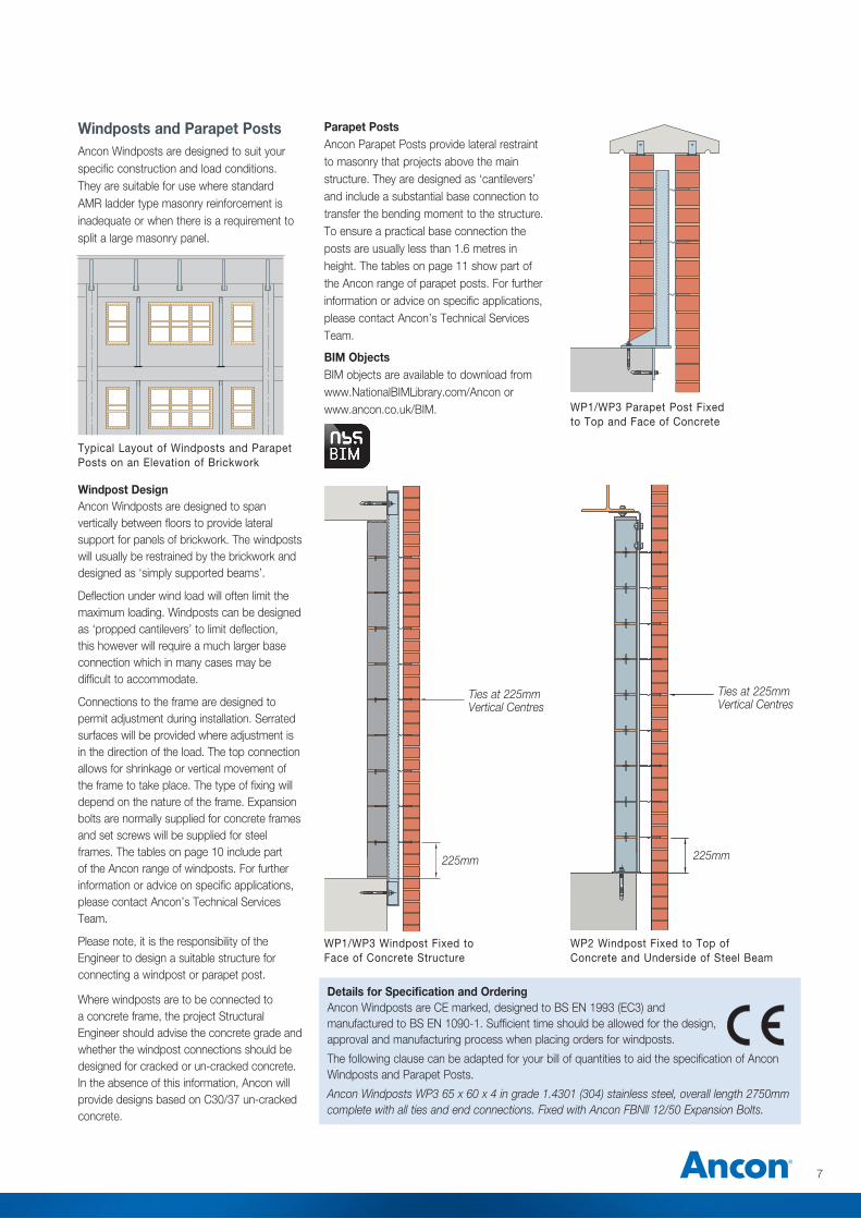
Windposts and Parapet PostsAncon Windposts are designed to suit your specific construction and load conditions. They are suitable for use where standard AMR ladder type masonry reinforcement is inadequate or when there is a requirement to split a large masonry panel.
7
Windpost DesignAncon Windposts are designed to span vertically between floors to provide lateral support for panels of brickwork. The windposts will usually be restrained by the brickwork and designed as ‘simply supported beams’.
Deflection under wind load will often limit the maximum loading. Windposts can be designed as ‘propped cantilevers’ to limit deflection, this however will require a much larger base connection which in many cases may be difficult to accommodate.
Connections to the frame are designed to permit adjustment during installation. Serrated surfaces will be provided where adjustment is in the direction of the load. The top connection allows for shrinkage or vertical movement of the frame to take place. The type of fixing will depend on the nature of the frame. Expansion bolts are normally supplied for concrete frames and set screws will be supplied for steel frames. The tables on page 10 include part of the Ancon range of windposts. For further information or advice on specific applications, please contact Ancon’s Technical Services Team.
Please note, it is the responsibility of the Engineer to design a suitable structure for connecting a windpost or parapet post.
Where windposts are to be connected to a concrete frame, the project Structural Engineer should advise the concrete grade and whether the windpost connections should be designed for cracked or un-cracked concrete. In the absence of this information, Ancon will provide designs based on C30/37 un-cracked concrete.
WP1/WP3 Windpost Fixed to Face of Concrete Structure
WP2 Windpost Fixed to Top of Concrete and Underside of Steel Beam
225mm 225mm
Ties at 225mm Vertical Centres
Ties at 225mm Vertical Centres
Details for Specification and OrderingAncon Windposts are CE marked, designed to BS EN 1993 (EC3) and manufactured to BS EN 1090-1. Sufficient time should be allowed for the design, approval and manufacturing process when placing orders for windposts.
The following clause can be adapted for your bill of quantities to aid the specification of Ancon Windposts and Parapet Posts.
Ancon Windposts WP3 65 x 60 x 4 in grade 1.4301 (304) stainless steel, overall length 2750mm complete with all ties and end connections. Fixed with Ancon FBNll 12/50 Expansion Bolts.
Parapet PostsAncon Parapet Posts provide lateral restraint to masonry that projects above the main structure. They are designed as ‘cantilevers’ and include a substantial base connection to transfer the bending moment to the structure. To ensure a practical base connection the posts are usually less than 1.6 metres in height. The tables on page 11 show part of the Ancon range of parapet posts. For further information or advice on specific applications, please contact Ancon’s Technical Services Team.
Typical Layout of Windposts and Parapet Posts on an Elevation of Brickwork
WP1/WP3 Parapet Post Fixed to Top and Face of Concrete
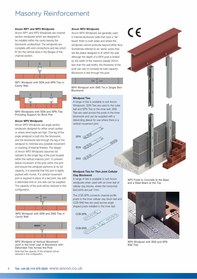
WP1 Windpost with SDN and SPN Ties in Cavity Wall
WP3 Windposts with SDN and SPN Ties Providing Support for Brick Pier
WP2 Windpost with SDN and SNS Ties in Cavity Wall
WP2 Windpost at Vertical Movement Joint in the Inner Leaf of Blockwork with Debonded Ties Across the PostNote that the capacity of the windpost will be reduced in this configuration.
WP4 Windpost with SNS Tie in Single Skin Blockwork
Ancon WP4 WindpostsAncon WP4 Windposts are generally used in internal blockwork walls that have a ‘fair faced’ finish to both sides and where the windposts cannot protrude beyond either face. Sometimes referred to as ‘spine’ posts they are flat plates designed to fit within the wall. Although the depth of a WP4 post is limited by the width of the masonry (ideally 20mm less than the wall width), the thickness of the post can vary to increase its load capacity. Blockwork is tied through the post.
Ancon WP2 WindpostsAncon WP2 Windposts are angle section windposts designed for either small cavities or where wind loads are high. One leg of the angle windpost is built into the blockwork, and the blockwork tied through the leg of the windpost to minimise any possible movement or cracking of internal finishes. The design of Ancon WP2 Windposts assumes full restraint to the longer leg of the post located within the vertical masonry joint. To prevent lateral movement of the post within this joint and ensure the windpost performs to its full capacity, it is essential that this joint is tightly packed with mortar. If a vertical movement joint is required in place of a tied joint, ties with a debonded end on one side can be supplied. The capacity of the post will be reduced in this configuration.
Ancon WP1 and WP3 WindpostsAncon WP1 and WP3 Windposts are channel section windposts which are designed to be installed within the cavity leaving the blockwork undisturbed. The windposts are complete with end connections and ties which fit into the vertical slots in the flanges of the channel section.
Masonry Reinforcement
WP3 Fixed to Concrete at the Base and a Steel Beam at the Top
WP2 Windpost with SNS and SPN Wall Ties
8 Tel: +44 (0) 114 275 5224 www.ancon.co.uk
Windpost TiesA range of ties is available to suit Ancon Windposts. SDN Ties are used to the outer leaf and SPN Ties to the inner leaf. SNS Ties are used across the posts in the inner blockwork and can be supplied with a debonding sleeve for use where there is a vertical movement joint.
SPN
SDN
SNS
CCB-SPN
CCB-SNS
Windpost Ties for Thin-Joint Cellular Clay BlockworkA range of ties is available to suit Ancon windposts when used with an inner leaf of cellular clay blocks, where the horizontal bed joints are just 1mm.
The CCB-SPN connects channel profile posts to the inner cellular clay block leaf and CCB-SNS ties are used across angle shaped posts installed in the inner leaf.
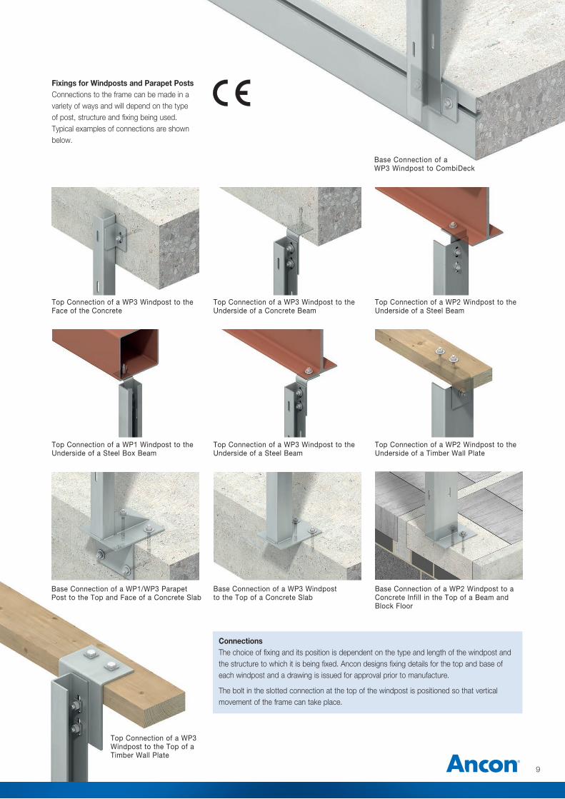
Base Connection of a WP3 Windpost to CombiDeck
Fixings for Windposts and Parapet PostsConnections to the frame can be made in a variety of ways and will depend on the type of post, structure and fixing being used. Typical examples of connections are shown below.
Top Connection of a WP2 Windpost to the Underside of a Timber Wall Plate
Top Connection of a WP3 Windpost to the Underside of a Steel Beam
Top Connection of a WP1 Windpost to the Underside of a Steel Box Beam
Top Connection of a WP3 Windpost to the Top of a Timber Wall Plate
Base Connection of a WP1/WP3 Parapet Post to the Top and Face of a Concrete Slab
Top Connection of a WP3 Windpost to the Face of the Concrete
Top Connection of a WP3 Windpost to the Underside of a Concrete Beam
Top Connection of a WP2 Windpost to the Underside of a Steel Beam
Base Connection of a WP2 Windpost to a Concrete Infill in the Top of a Beam and Block Floor
Base Connection of a WP3 Windpost to the Top of a Concrete Slab
9
ConnectionsThe choice of fixing and its position is dependent on the type and length of the windpost and the structure to which it is being fixed. Ancon designs fixing details for the top and base of each windpost and a drawing is issued for approval prior to manufacture.
The bolt in the slotted connection at the top of the windpost is positioned so that vertical movement of the frame can take place.
Masonry Reinforcement
10 Tel: +44 (0) 114 275 5224 www.ancon.co.uk
Size Design Resistance (kN) per Post (uniformly distributed) for Various Windpost Spans a x b x t 2.5m 3.0m 3.5m 4.0m 4.5m 5.0m 5.5m 6.0m
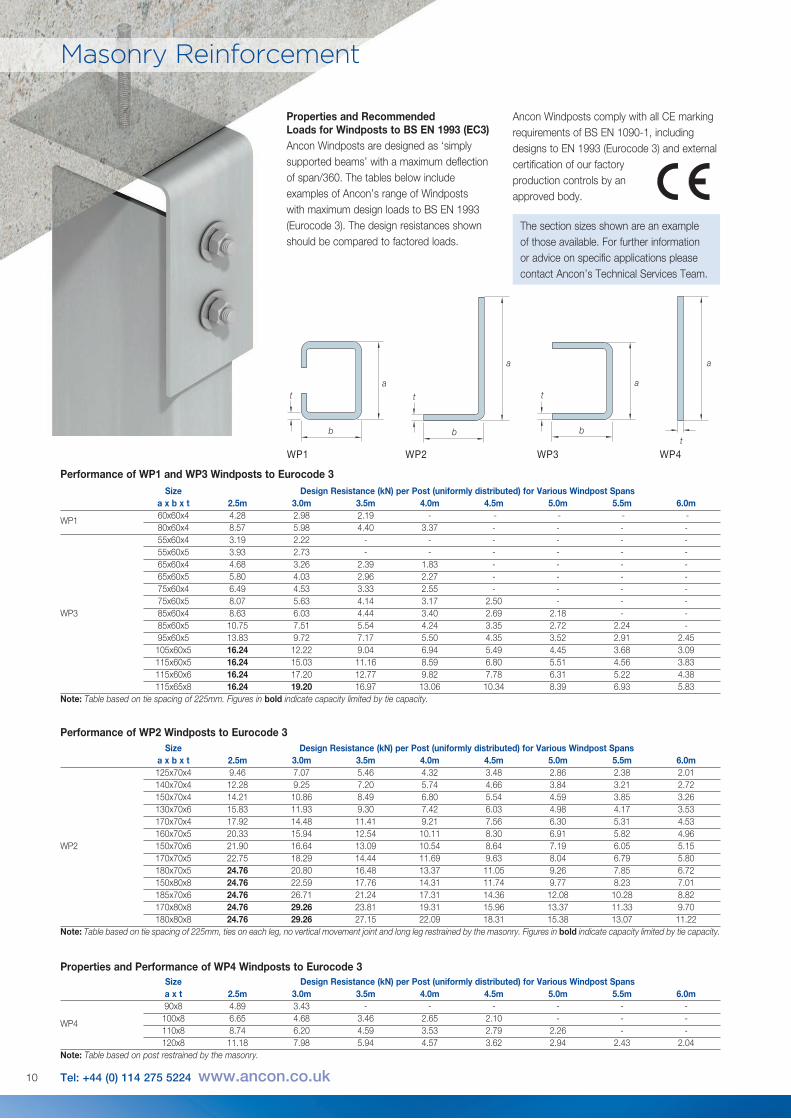
WP1 60x60x4 4.28 2.98 2.19 - - - - - 80x60x4 8.57 5.98 4.40 3.37 - - - - 55x60x4 3.19 2.22 - - - - - - 55x60x5 3.93 2.73 - - - - - - 65x60x4 4.68 3.26 2.39 1.83 - - - - 65x60x5 5.80 4.03 2.96 2.27 - - - - 75x60x4 6.49 4.53 3.33 2.55 - - - - 75x60x5 8.07 5.63 4.14 3.17 2.50 - - -WP3 85x60x4 8.63 6.03 4.44 3.40 2.69 2.18 - - 85x60x5 10.75 7.51 5.54 4.24 3.35 2.72 2.24 - 95x60x5 13.83 9.72 7.17 5.50 4.35 3.52 2.91 2.45 105x60x5 16.24 12.22 9.04 6.94 5.49 4.45 3.68 3.09 115x60x5 16.24 15.03 11.16 8.59 6.80 5.51 4.56 3.83 115x60x6 16.24 17.20 12.77 9.82 7.78 6.31 5.22 4.38 115x65x8 16.24 19.20 16.97 13.06 10.34 8.39 6.93 5.83Note: Table based on tie spacing of 225mm. Figures in bold indicate capacity limited by tie capacity.
a
b
t
Properties and Recommended Loads for Windposts to BS EN 1993 (EC3)Ancon Windposts are designed as ‘simply supported beams’ with a maximum deflection of span/360. The tables below include examples of Ancon’s range of Windposts with maximum design loads to BS EN 1993 (Eurocode 3). The design resistances shown should be compared to factored loads.
WP2
a
t
a
b
t
WP3 WP4WP1
a
b
t
Performance of WP1 and WP3 Windposts to Eurocode 3
Size Design Resistance (kN) per Post (uniformly distributed) for Various Windpost Spans a x b x t 2.5m 3.0m 3.5m 4.0m 4.5m 5.0m 5.5m 6.0m 125x70x4 9.46 7.07 5.46 4.32 3.48 2.86 2.38 2.01 140x70x4 12.28 9.25 7.20 5.74 4.66 3.84 3.21 2.72 150x70x4 14.21 10.86 8.49 6.80 5.54 4.59 3.85 3.26 130x70x6 15.83 11.93 9.30 7.42 6.03 4.98 4.17 3.53 170x70x4 17.92 14.48 11.41 9.21 7.56 6.30 5.31 4.53 160x70x5 20.33 15.94 12.54 10.11 8.30 6.91 5.82 4.96WP2 150x70x6 21.90 16.64 13.09 10.54 8.64 7.19 6.05 5.15 170x70x5 22.75 18.29 14.44 11.69 9.63 8.04 6.79 5.80 180x70x5 24.76 20.80 16.48 13.37 11.05 9.26 7.85 6.72 150x80x8 24.76 22.59 17.76 14.31 11.74 9.77 8.23 7.01 185x70x6 24.76 26.71 21.24 17.31 14.36 12.08 10.28 8.82 170x80x8 24.76 29.26 23.81 19.31 15.96 13.37 11.33 9.70 180x80x8 24.76 29.26 27.15 22.09 18.31 15.38 13.07 11.22Note: Table based on tie spacing of 225mm, ties on each leg, no vertical movement joint and long leg restrained by the masonry. Figures in bold indicate capacity limited by tie capacity.
Performance of WP2 Windposts to Eurocode 3
Size Design Resistance (kN) per Post (uniformly distributed) for Various Windpost Spans a x t 2.5m 3.0m 3.5m 4.0m 4.5m 5.0m 5.5m 6.0m 90x8 4.89 3.43 - - - - - -
WP4 100x8 6.65 4.68 3.46 2.65 2.10 - - - 110x8 8.74 6.20 4.59 3.53 2.79 2.26 - - 120x8 11.18 7.98 5.94 4.57 3.62 2.94 2.43 2.04Note: Table based on post restrained by the masonry.
Properties and Performance of WP4 Windposts to Eurocode 3
The section sizes shown are an example of those available. For further information or advice on specific applications please contact Ancon’s Technical Services Team.
Ancon Windposts comply with all CE marking requirements of BS EN 1090-1, including designs to EN 1993 (Eurocode 3) and external certification of our factory production controls by an approved body.
11
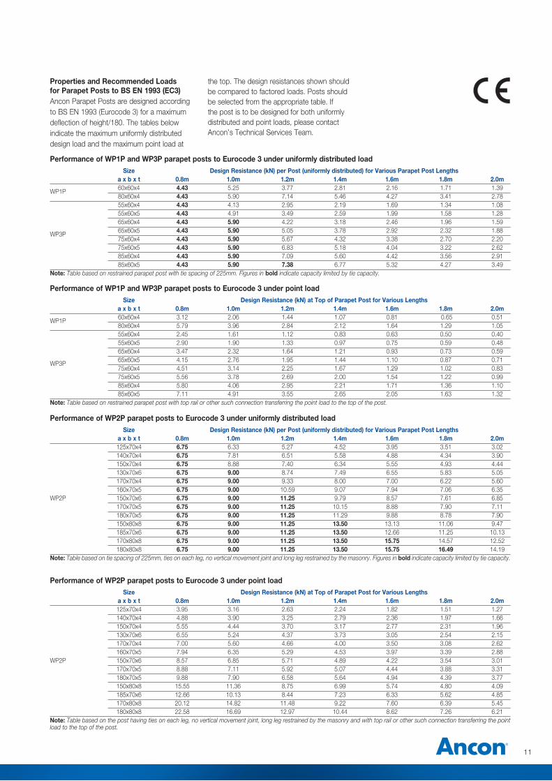
Properties and Recommended Loads for Parapet Posts to BS EN 1993 (EC3)Ancon Parapet Posts are designed according to BS EN 1993 (Eurocode 3) for a maximum deflection of height/180. The tables below indicate the maximum uniformly distributed design load and the maximum point load at
the top. The design resistances shown should be compared to factored loads. Posts should be selected from the appropriate table. If the post is to be designed for both uniformly distributed and point loads, please contact Ancon’s Technical Services Team.
Size Design Resistance (kN) per Post (uniformly distributed) for Various Parapet Post Lengths a x b x t 0.8m 1.0m 1.2m 1.4m 1.6m 1.8m 2.0m
WP1P 60x60x4 4.43 5.25 3.77 2.81 2.16 1.71 1.39 80x60x4 4.43 5.90 7.14 5.46 4.27 3.41 2.78 55x60x4 4.43 4.13 2.95 2.19 1.69 1.34 1.08 55x60x5 4.43 4.91 3.49 2.59 1.99 1.58 1.28 65x60x4 4.43 5.90 4.22 3.18 2.46 1.96 1.59
WP3P 65x60x5 4.43 5.90 5.05 3.78 2.92 2.32 1.88 75x60x4 4.43 5.90 5.67 4.32 3.38 2.70 2.20 75x60x5 4.43 5.90 6.83 5.18 4.04 3.22 2.62 85x60x4 4.43 5.90 7.09 5.60 4.42 3.56 2.91 85x60x5 4.43 5.90 7.38 6.77 5.32 4.27 3.49Note: Table based on restrained parapet post with tie spacing of 225mm. Figures in bold indicate capacity limited by tie capacity.
Performance of WP1P and WP3P parapet posts to Eurocode 3 under uniformly distributed load
Size Design Resistance (kN) at Top of Parapet Post for Various Lengths a x b x t 0.8m 1.0m 1.2m 1.4m 1.6m 1.8m 2.0m
WP1P 60x60x4 3.12 2.06 1.44 1.07 0.81 0.65 0.51 80x60x4 5.79 3.96 2.84 2.12 1.64 1.29 1.05 55x60x4 2.45 1.61 1.12 0.83 0.63 0.50 0.40 55x60x5 2.90 1.90 1.33 0.97 0.75 0.59 0.48 65x60x4 3.47 2.32 1.64 1.21 0.93 0.73 0.59
WP3P 65x60x5 4.15 2.76 1.95 1.44 1.10 0.87 0.71 75x60x4 4.51 3.14 2.25 1.67 1.29 1.02 0.83 75x60x5 5.56 3.78 2.69 2.00 1.54 1.22 0.99 85x60x4 5.80 4.06 2.95 2.21 1.71 1.36 1.10 85x60x5 7.11 4.91 3.55 2.65 2.05 1.63 1.32Note: Table based on restrained parapet post with top rail or other such connection transferring the point load to the top of the post.
Performance of WP1P and WP3P parapet posts to Eurocode 3 under point load
Size Design Resistance (kN) per Post (uniformly distributed) for Various Parapet Post Lengths a x b x t 0.8m 1.0m 1.2m 1.4m 1.6m 1.8m 2.0m 125x70x4 6.75 6.33 5.27 4.52 3.95 3.51 3.02 140x70x4 6.75 7.81 6.51 5.58 4.88 4.34 3.90 150x70x4 6.75 8.88 7.40 6.34 5.55 4.93 4.44 130x70x6 6.75 9.00 8.74 7.49 6.55 5.83 5.05 170x70x4 6.75 9.00 9.33 8.00 7.00 6.22 5.60 160x70x5 6.75 9.00 10.59 9.07 7.94 7.06 6.35WP2P 150x70x6 6.75 9.00 11.25 9.79 8.57 7.61 6.85 170x70x5 6.75 9.00 11.25 10.15 8.88 7.90 7.11 180x70x5 6.75 9.00 11.25 11.29 9.88 8.78 7.90 150x80x8 6.75 9.00 11.25 13.50 13.13 11.06 9.47 185x70x6 6.75 9.00 11.25 13.50 12.66 11.25 10.13 170x80x8 6.75 9.00 11.25 13.50 15.75 14.57 12.52 180x80x8 6.75 9.00 11.25 13.50 15.75 16.49 14.19Note: Table based on tie spacing of 225mm, ties on each leg, no vertical movement joint and long leg restrained by the masonry. Figures in bold indicate capacity limited by tie capacity.
Performance of WP2P parapet posts to Eurocode 3 under uniformly distributed load
Size Design Resistance (kN) at Top of Parapet Post for Various Lengths a x b x t 0.8m 1.0m 1.2m 1.4m 1.6m 1.8m 2.0m 125x70x4 3.95 3.16 2.63 2.24 1.82 1.51 1.27 140x70x4 4.88 3.90 3.25 2.79 2.36 1.97 1.66 150x70x4 5.55 4.44 3.70 3.17 2.77 2.31 1.96 130x70x6 6.55 5.24 4.37 3.73 3.05 2.54 2.15 170x70x4 7.00 5.60 4.66 4.00 3.50 3.08 2.62 160x70x5 7.94 6.35 5.29 4.53 3.97 3.39 2.88WP2P 150x70x6 8.57 6.85 5.71 4.89 4.22 3.54 3.01 170x70x5 8.88 7.11 5.92 5.07 4.44 3.88 3.31 180x70x5 9.88 7.90 6.58 5.64 4.94 4.39 3.77 150x80x8 15.55 11.36 8.75 6.99 5.74 4.80 4.09 185x70x6 12.66 10.13 8.44 7.23 6.33 5.62 4.85 170x80x8 20.12 14.82 11.48 9.22 7.60 6.39 5.45 180x80x8 22.58 16.69 12.97 10.44 8.62 7.26 6.21Note: Table based on the post having ties on each leg, no vertical movement joint, long leg restrained by the masonry and with top rail or other such connection transferring the point load to the top of the post.
Performance of WP2P parapet posts to Eurocode 3 under point load
The construction applications and details provided in this literature are indicative only. In every case, project working details should be entrusted to appropriately qualified and experienced persons.
Whilst every care has been exercised in the preparation of this document to ensure that any advice, recommendations or information is accurate, no liability or responsibility of any kind is accepted in respect of Ancon.
With a policy of continuous product development Ancon reserves the right to modify product design and specification without due notice.
© Ancon
These products are available from:
Ancon Building Products 98 Kurrajong Avenue Mount Druitt Sydney NSW 2770 Australia Tel: +61 (0) 2 8808 3100 Fax: +61 (0) 2 9675 3390 Email: [email protected] Visit: www.ancon.com.au
Ancon Building Products 2/19 Nuttall DriveHillsboroughChristchurch 8022New ZealandTel: +64 (0) 3 376 5205Fax: +64 (0) 3 376 5206Email: [email protected] Visit: www.ancon.co.nz
Ancon (Schweiz) AG Gewerbezone Widalmi 10 3216 Ried bei Kerzers Switzerland Tel: +41 (0) 31 750 3030 Fax: +41 (0) 31 750 3033 Email: [email protected] Visit: www.ancon.ch
Ancon Building Products GesmbH Puchgasse 1A-1220 ViennaAustria Tel: +43 (0) 1 259 58 62-0 Fax: +43 (0) 1 259 58 62-40 Email: [email protected] Visit: www.ancon.at
Ancon GmbH Bartholomäusstrasse 26 90489 Nuremberg Germany Tel: +49 (0) 911 955 1234 0 Fax: +49 (0) 911 955 1234 9 Email: [email protected] Visit: www.anconbp.de
Ancon Ltd President Way, President Park Sheffield S4 7UR United Kingdom Tel: +44 (0) 114 275 5224 Fax: +44 (0) 114 276 8543 Email: [email protected] Visit: www.ancon.co.uk Follow on Twitter: @AnconUK
Ancon (Middle East) FZE PO Box 17225 Jebel Ali Dubai United Arab Emirates Tel: +971 (0) 4 883 4346 Fax: +971 (0) 4 883 4347 Email: [email protected] Visit: www.ancon.ae
Masonry Support Systems
Lintels
Windposts and Masonry Reinforcement
Wall Ties and Restraint Fixings
Channel and Bolt Fixings
Tension and Compression Systems
Insulated Balcony Connectors
Shear Load Connectors
Punching Shear Reinforcement
Reinforcing Bar Couplers
Reinforcement Continuity Systems
Stainless Steel Fabrications
Flooring and Formed Sections
Refractory Fixings