Embed Size (px)
Citation preview
Vibration control of wind turbine tower-nacelle model
with magnetorheological tuned vibration absorber Paweł Martynowicz
AGH University of Science and Technology Department of Process Control
Abstract
Wind turbine tower dynamic load is related to the fatigue and reliability of the structure This paper
deals with the problem of tower vibration control using specially designed and built numerical and
laboratory model The regarded wind turbine tower-nacelle model consists of vertically arranged stiff
rod (representing the tower) and a stiff body fixed at its top representing nacelle assembly that is
equipped with horizontally aligned tuned vibration absorber (TVA) with magnetorheological (MR)
damper To model tower-nacelle dynamics Comsol Multiphysics finite element method environment
was used For time and frequency domain numerical analyses (including first and second bending
modes of vibration) of system with TVA and MR damper models MATLABSimulink environment
was used with Comsol Multiphysics tower-nacelle model embedded Force excitation sources applied
horizontally to the nacelle and to the tower itself were both considered The MR damper real-time
control algorithms including ground hook control and its modification sliding mode control linear
and nonlinear (cubic and square root) damping and adaptive solutions are compared to the open-loop
case with various constant MR damper input current values and system without MRTVA (ie
MRTVA in lsquolockedrsquo state) Comprehensive numerical analyses results are presented along with
Vensys 82 full-scale tower-nacelle model validation Finally preliminary results of laboratory tests are
included
Keywords
Wind turbine tower vibration tuned vibration absorber MR damper vibration control tower-nacelle model
Introduction
Wind turbines are emerging renewable energy extraction solutions nowadays The wind load (and also
sea waves load for the offshore structures) that is varying in time as well as rotation of turbine
elements are the major contributors to the structural vibration of tower and blades Cyclic stress that
tower is subjected to may lead to the decrease in reliable operation time due to structure fatigue wear
(Enevoldsen and Mork 1996) or even failure accident Tower vibration arises due to various
excitation sources as variable wind conditions including wind shear Karman vortices blade passing
effect rotating elements unbalance sea waves ice etc (Jain 2011) This vibration is generally lightly
damped Damping ratio for the first two tower bending modes is usually less than or equal to 05
excluding aerodynamic damping (Butt and Ishihara 2011 Hansen et al 2012 Matachowski and
Martynowicz 2012) The aeroelastic damping for the first tower longitudinal mode is usually of the
order of ten times greater than for the first tower lateral mode (Bak et al 2012 Hansen et al 2012)
The lateral modes of the tower are excited due to Karman vortices generator operation sea waves
variable load and rotating machinery unbalance rather than due to direct wind load variation and blade
passing effect as for longitudinal modes In current project tower vibration is analysed on the basis of
specially developed and built tower-nacelle simulation and laboratory models in which all turbine
components (nacelle blades hub shaft generator and possibly gearbox) are represented by nacelle
concentrated mass and mass moments of inertia
The main solutions utilised to reduce wind turbines towersrsquo vibration are collective pitch angle
control of the blades (cancellation of 3p excitation arising due to differences in inflow conditions for
each of the blades and blade passing effect (p is rotor frequency)) and generator electromagnetic
torque control (Jelavić et al 2007 Namik and Stol 2011 Shan and Shan 2012) Passive semiactive
Corresponding author
Paweł Martynowicz AGH University of Science and Technology Department of Process Control
al Mickiewicza 30 30-059 Krakoacutew Poland
Email pmartynaghedupl
active tuned vibration absorbers (TVAs) (Den Hartog 1985) are gaining more and more interest in
wind turbines applications (Enevoldsen and Mork 1996 Rotea et al 2010 Tsouroukdissian et al
2011 Oh and Ishihara 2013) TVAs are widely spread structural vibration reduction solutions for
slender structures including towers high buildings chimneys etc In the standard (passive) approach
TVA is being installed atclose to the top of the structure and it consists of the additional moving
mass spring and viscous damper which parameters are tuned to the selected (most often first) mode
of structure vibration (Den Hartog 1985 Łatas and Martynowicz 2012) Passive TVAs work well at
the load conditions characterised with a single frequency to which they are tuned but can not adapt to
wide excitation spectrum (comprising eg 3p frequency) (Kirkegaard et al 2002) Moreover in real
world conditions frequency response of such low-damped structures as wind turbinesrsquo towers may
exhibit some fluctuations in time (Butt and Ishihara 2011) thus more advanced TVA approaches
consider adaptive stiffness and damping solutions to changetune TVA operating frequency Among
these solutions magnetorheological (MR) TVAs are placed (Kirkegaard et al 2002) MRTVAs are
TVAs equipped with MR dampers instead of passive viscous dampers (Koo and Ahmadian 2007)
MR dampers are semiactive actuators characterised with simplicity of construction and minor energy
requirements as compared with active systems They utilise specific properties of MR fluid which
changes its apparent viscosity in the presence of magnetic field MR dampers are filled with such a
fluid and equipped with electrical windings to generate magnetic field thus they provide a wide range
of resistance force fast response times low sensitivity to temperature and contamination and high
operational robustness When MR damper deteriorates it usually still behaves as a passive shock-
absorber (Lord Rheonetic 2002 Sapiński B and Rosoacuteł M 2008 Sapiński B 2011 Kciuk and
Martynowicz 2011) As simulations and experiments show implementation of MR damper in TVA
system may lead to further vibration reduction in relation with passive TVA
Several approaches to the problem of wind turbine tower vibration control with MRTVA are
presented Throughout them ground hook control and its modification sliding mode control linear
and nonlinear damping adaptive control and open-loop solutions with various MR damper input
current values are regarded in comparison with system without TVA (ie TVA lsquolockedrsquo by
appropriately high input current fed to MR damper coil) First and second bending mode of vibration
are both analysed Two independent horizontal concentrated force excitation sources are considered
the first one (designated by P(t)) applied to the nacelle the second one (designated by F(t)) applied to
the tower midpoint
The paper is organised as follows In the forthcoming section wind turbine tower-nacelle theoretical
and Comsol-Simulink models are introduced Than vibration control algorithms are presented and
followed by simulations results Laboratory test rig along with preliminary tests results are presented
next Paper is finished with several conclusions
Wind turbine tower-nacelle model
Theoretical model
The model to be analysed consists of stiff rod arranged vertically representing wind-turbine tower
and a stiff body connected rigidly to the top of the rod representing both nacelle and turbine
assemblies The bottom end of the rod (tower) is fixed to the ground via additional foundation As the
first tower bending mode has dominant modal mass participation (ca fivefold greater than the next
mode) vibration reduction system that comprises spring and MR damper (built in parallel) with an
additional stiff body operating all together as TVA is located at the top of the tower (at nacelle) The
horizontal disturbance load provided in the laboratory conditions by the dedicated modal shaker may
either be concentrated at the nacelle or applied to the arbitrary tower section both locations enable to
force tower bending modes of vibration The MRTVA direction of operation is the same as direction
of applied excitation (assuming small bending angles)
Regarded model has to fulfil various constraints among other adequate dimensions adequate yield
strength and modal masses of the structure mass of the absorber all corresponding to the
commercially available MR damper characteristics to enable reduction of tower deflection amplitude
for the allowable MR damper stroke and force ranges as well as at least partial dynamic similarity
(similarity of motions of tower tips) between real-world wind turbine tower-nacelle system and its
scaled model fulfilled while respecting limited laboratory space and foundation permissible load
(Martynowicz 2014a Martynowicz and Szydło 2014 Snamina et al 2014) Based on all the
assumptions and thorough analyses results Ti Gr 5 rod was selected to model wind turbine tower
while Lord Co RD 1097-1 (Lord Rheonetic 2002) was utilised as TVA MR damper The parameters
of TVA were tuned for the first bending mode of vibration (Den Hartog 1985 Łatas and
Martynowicz 2012) The absorber mass m2 was selected to be 10 of the modal mass of the first
bending mode of tower-nacelle model m1 (ie mass ratio was micro= m2m1=01) Schematic diagram of
the system idea is presented in Figure 1 while detailed parameters of the model are collected in the
Table 1 below (Scaled simulation model column) TVA optimal damping is 1296 Nsm The detailed
theoretical calculation analyses comprising Euler Bernoulli beam mathematical model finite element
method (FEM) Comsol Multiphysics model and dynamic similarity with Vensys 82 baseline case
including similarity of lengths (deflections) time (natural frequencies) system damping and forces
are not citied here as are covered thoroughly by previous papers (Łatas and Martynowicz 2012
Matachowski and Martynowicz 2012 Snamina and Martynowicz 2014 Snamina et al 2014)
Figure 1 Sketch of the tower-nacelle model with MRTVA
Comsol-Simulink model
As the idea of current research project was to investigate dynamics of wind turbine tower-nacelle
model only together with specially developed vibration reduction system (comprising MRTVA) all
turbine components were reduced to mass and mass moments of inertia while all the aerodynamic
loads turbine or tower are subjected to were represented by concentrated forces applied to the nacelle
(tower tip) or to the tower section itself The fundamental emphasis was put on control algorithms
design synthesis and testing as well as laboratory test rig development thus MATLABSimulink
software as one of the most appropriate server tools with Comsol Multiphysics environment as FEM
client were selected instead of Bladed FAST SAMCEF SIMPACK or other solutions
Regarding these assumptions Comsol Multiphysics FEM model of tower-nacelle system was
developed and embedded in Simulink environment The tower-nacelle model was build as a vertical
beam fixed at the bottom and free at the top with an additional mass and mass moments of inertia
defined at its top The model element type of lsquo3D Euler Beamrsquo (smeul3D) with three nodes (points)
and lsquotransientrsquo analysis type were selected (see Figure 2 (a)) Conducted comparative analysis of lsquo3D
Euler Beamrsquo with three and seven nodes proved minor influence of additional nodes introduction on
analyses results while very significant influence on computation time The two edges were configured
by applying material properties (Young modulus Poisson ratio density internal friction (Rayleigh
damping model) etc) cross-section dimensions and areas area moments of inertia and torsional
constant corresponding to the TiGr5 rod The bottom node represents tower-ground (tower-
foundation) restrain (constraint condition lsquoFixedrsquo) while two other nodes are lsquoFreersquo
Direct or indirect external (aerodynamic sea waves ice etc) tower loads may be reduced to the
resultant concentrated force applied at half of tower height Thus the node in the tower midpoint
(where deflection of the 2nd
mode is close to its maximum ndash see also Figure 2 (c)) is a lsquoload pointrsquo
where a horizontal x-axis force F (F(t)) may be applied The node at the top of the tower corresponds
to the nacelle location thus mass and mass moments of inertia as well as concentrated load P (P(t))
are all assigned here The load P acting along x-axis represents mainly wind thrust on the tower top
nacelle through the rotor The node at the top of the tower exhibits maximum deflection of the 1st
bending mode (Figure 2 (b))
(a)
(b) (c)
Figure 2 Comsol Multiphysics tower-nacelle FEM model
(a) 3D Euler Beam with three nodes (b) 1st mode shape (c) 2
nd mode shape
Such a FEM Comsol Multiphysics model was than exported to MATLAB Simulink During
exporting of Simulink model lsquoSimulink block typersquo General Dynamic was selected forces F P were
specified as inputs while tower tip nacelle horizontal displacement x1 and velocity v1 and tower
midpoint displacement x0 along x-axis were defined as three output signals After exporting FEM
tower-nacelle model was available as MATLAB structure and Comsol Multiphysics model was
embedded in Simulink diagram using COMSOL Multiphysics Subsystem block with Sine Wave
generators P and F as its input signals with amplitudes P0 and F0 (respectively) and To Workspace
blocks as outputs TVA model acting along x-axis was built-in the Simulink diagram Signals x1 and v1
were fed to the dynamics of TVA that was modelled by mass damping and stiffness parameters m2 c2
and k2 (Den Hartog 1985 Łatas and Martynowicz 2012) for the passive case respectively By x2
absorber (TVA mass) horizontal displacement was designated (while v2 will denote absorber
horizontal velocity) If MR damper was used instead of the passive viscous damper MR damper
hyperbolic tangent model (RD-1097-1 model) in the form of (Maślanka et al 2007)
212102121 pptanh xxxxcxxxxPP cMR (1)
was embedded in Simulink (Figure 3) instead of Gain block modelling c2 In (1) MRP is the force
produced by the MR damper cP and 0c are current-dependent friction force and viscous damping
coefficients and p are scaling parameters while 1x and 2x are derivatives of x1 and x2 with respect
to time (respectively) Forces generated by (MR) TVA acting along x-axis at the nacelle (tower tip)
were added with appropriate signs to the force P Figure 3 presents Simulink model of such a system
with MRTVA
k2
x0
v1
FFx
PPx
x2
PMR
x1
displacement
v elocity
i
Force
RD-1097-1 model
P
1
s
Integrator2
1
s
Integrator1
F
ii
Current
P
F
x1
v 1
x0
COMSOL Multiphysics
Subsystem
1m2
Figure 3 Tower-nacelle FEM model embedded in Simulink
Control background
Considering nonzero MR damper response time and value of 2nd
bending mode frequency (ca 35 Hz)
(Figure 2 (c)) the main purpose of vibration reduction system and TVA implementation was to reduce
vibration (namely amplitudes of x0 and x1 ie A(x0) and A(x1)) corresponding to 1st tower-nacelle
bending mode only (Figure 2 (b)) thus TVA location was selected to be at the nacelle where naturally
appropriate necessary space may be available in real world conditions Such a location was also
dictated by implementation possibilities of MRTVA at the limited laboratory scale as dimensions of
the appropriate MR device are relatively significant
Equation-set (2) presents model of structure-MRTVA system reduced to 1st bending mode only
1 1 1 1 1 1 2 1 2
2 2 2 1 2
MR
MR
m x k x c x k x x P P
m x k x x P
(2)
where k1 and c1 represent modal stiffness and damping (respectively) corresponding to 1st bending
mode of regarded tower-nacelle model while excitation is applied horizontally to the tower tip
(nacelle) thus Pne0 and F=0 Using frequency-domain analysis assuming that P=P(t)=P0cos(ωt) (ω is
angular frequency) and solution is of the form x1=x1(t)=A(x1)cos(ωt+φ)=acos(ωt)+bsin(ωt)
x2=x2(t)=A(x2)cos(ωt+ψ)=ccos(ωt)+dsin(ωt) (a b c d are real constants) solving for a b c d one
may derive values of A(x1)=radic(a2+b
2) and A(x2)=radic(c
2+d
2) amplitudes as a function of excitation
frequency
Analogically assuming also that 2 21 21 1( ) ( ) ( ) ( )x x x x A xt x cot t st t one can obtain
φ=arctg(ndashba) ψ=arctg(ndashdc) θ=arctg[(radic(a2+b
2)
ωcosφndashradic(c
2+d
2)ωcosψ)([(ndashradic(a
2+b
2)ωsinφ+radic(c
2+d
2)ωsinψ)]
with necessary corrections by ndashπ due to periodic nature of tangent function and expected phase characteristics
of two degree-of-freedom vibration system elements
Figure 4(a) presents tower tip displacement amplitude A(x1) output frequency response functions
calculated for excitation amplitude P0=305 N assuming various PMR functions (see legend c2 is
damping coefficient of passive TVA tuned according to (Den Hartog 1985)) Of course in real-world
case MR damper force comprises not only viscous but also friction and stiffness component As can
be observed reference characteristics (MR damper producing standardndashpassive TVA damper force
thick solid black line) exhibits lowest (two) maxima values equal to 096middot10ndash3
m However there is a
field of further reduction of tower deflection amplitudes by adequate changing of (controlling) MR
damper force namely by increasing damper force in the vicinities of mentioned (two) maxima
frequencies (as for thin solid black line) and decreasing damper force in between the frequencies of
the two maxima (see dotted line while grey line characteristics is not practically achievable with the
use of MR damper) Figure 4(b) presents phase shift (φndashθ) frequency characteristic for
PMR=c2(v1ndashv2)= 2 1 2 )(c x x Phase shift between x1 and 21 )(x x is one of the most frequently utilised
and most efficient concepts of TVA control in this paper GND and indirectly ModGND algorithms
(described in the next section) outputs are based on signs of x1 and 21 )(x x functions When signs of
x1 and 21 )(x x are the same MR damper force should be maximal while when signs are opposite
MR damper force should be minimal according to well known ground-hook principle as such a
control leads to vibration minimisation of the protected structure
25 3 35 4 45 5 550
05
1
15
2
x 10-3
To
we
r tip
dis
pla
ce
me
nt
am
plitu
de
[m
]
Frequency [Hz]
PMR
= 0
PMR
= 03c
2(v
1-v
2)
PMR
= 1c
2(v
1-v
2)
PMR
= 3c
2(v
1-v
2)
25 3 35 4 45 5 55
157
314
471
Frequency [Hz]
Ph
ase
sh
ift b
etw
ee
n x
1 a
nd
(v 1
-v2)
[rd
]
PMR
= 1c
2(v
1-v
2)
Figure 4 (a) Tower tip displacement amplitude A(x1) output frequency response functions
(b) Phase shift (φndashθ) frequency characteristic
As can be observed (Figure 4(b)) phase shift (φndashθ) is π at 363 Hz (at which A(x1)=0 for zero damping
configuration see Figure 4(a)) Thus x1 and 21 )(x x patterns are exactly out-of-phase at 363 Hz
(where zero damper force is preferable) so equation (4) (and indirectly (5)) yields zero output ie
minimum MR damper force This is also to a large extent the case for all the frequencies between
333 Hz and 439 Hz at which two invariant points of amplitude responses appear (Figure 4(a))
resulting small MR damper forces within (333 439) Hz range Outside this range MR damper forces
are maximal in wider intervals as time intervals in which x1 and 21 )(x x patterns have the same
signs are wider due to the fact that phase shift (φndashθ) noticeably differs from value of π (out-of-phase
state)
(a)
(b)
05π
π
15π
Details of MR damper control algorithms and their implementation along with simulation analyses and
laboratory tests results (validating current section analysis) are presented in the following sections
Control algorithms
Overview of several approaches to the problem of wind turbine tower-nacelle model vibration control
with MRTVA is presented here With the use of MR damper standard TVA linear damping algorithm
(designated by C) (Den Hartog 1985) may be realised as well as other dedicated solutions
Throughout them ground hook control (GND) and its modification (ModGND) sliding mode control
(SMC) nonlinear damping including cubic damping (C3) and square root damping (SQRT) adaptive
MRTVA control (ADPT) and open-loop (passive) solutions with 00A 01A 02A and 03A input
MR damper current are regarded in comparison with system without TVA (ie TVA lsquolockedrsquo by MR
damper current of 10 A) 1st and 2
nd bending mode of vibration are both analysed As stated above
two independent force excitation sources are considered one applied horizontally to the nacelle P
(P(t)) the other applied to the tower itself at half of its height F (F(t)) As P(t) is mostly considered to
activate the 1st bending mode of vibration F(t) is devoted to efficiently stimulate the 2
nd mode
however obviously both modes may be activated by either of the excitation sources
The aim of MRTVA implementation was to reduce tower vibration to even further extend than
standard (passive) TVA does The control strategies that have been employed to determine MR
damper current during real-time operation are listed below
Ground-Hook control (GND)
This strategy was initially developed for vehicle suspension systems (Sapiński 2008) to minimise tire-
road dynamic forces However implementation of this simple principle for slender structure semi-
active TVA MRTVA is also possible and provides reduction of structure vibration (with relation to
the ground) at the point of its application (Shen et al 2013) The described principle implemented on
the MR damper (displacement ground-hook version) is represented by the formula
0 0
0
211
211max
xxx
xxxPP MRdesired
MR
thus (3)
max
1 1 2
1 1 2
0
0 0
MR
MR
i x x xi
x x x
(4)
where MRi is MR damper input current On the basis of thorough simulation analysis max
MRi = 10 A was
selected (Martynowicz 2014b)
Modified Ground-Hook control (ModGND)
The original ground-hook modification idea excerpted in this paper arises from the MR damper
hysteresis phenomenon During the sine excitation test for some part of the period ndash just after MR
damper velocity 21 xx sign change ndash MR damper behaves as an lsquoactiversquo device Although velocity
21 xx sign has already changed MR damper force sign is maintained for a short part of sine period
thus it may be used for vibration control This is not the case in TVA system with viscous damper
Basic idea underlying the modified ground-hook algorithm implemented on MR damper takes the
form
0 0
0
1
1max
MR
MRMRMR
Px
Pxii (5)
where max
MRi = 10 A was selected on the basis of simulation series Details of ModGND implementation
are to be presented in a separate publication
Sliding mode control (SMC)
Sliding mode control strategy is a nonlinear technique that is widely used due to its robustness and
ability to decouple high-dimension systems into a set of independent lower-dimension subsystems
(Neelakantan and Washington 2008) that is why it was selected for the present system vibration
control via MRTVA Nacelle-TVA dynamics only was regarded here The sliding surface was selected
to be 1 1s x x According to (Neelakantan and Washington 2008) sliding mode control law may be
expressed by equation
1ign 0
1ign
21
21max
xxss
xxssPP MRdesired
MR
(6)
thus
max
1 2
1 2
sign 1
0 sign 1
MR
MR
i s x xi
s x x
(7)
where max 10MRi A was selected on the basis of simulation series
Linear damping (C)
In this approach linear (viscous) damping force is being calculated by simple formula
2 1 2MR
desiredP c x x while internal feedback loop with MR damper real-time force measurement and PI
controller is implemented in such a force follow-up control algorithm PI controller settings are
proportional gain 215∙10ndash4
integral gain 02∙10ndash4
Details of implementation of damping force follow-
up control algorithm are presented in Figure 5(a) (Laalej et al 2012) with (0 1) A saturation limits
An alpha is measurement signal scaling factor
Nonlinear damping (C3 and SQRT)
Previous studies presented eg in (Laalej et al 2012) confirm beneficial effects of MR damper based
implementation of nonlinear damping for vibration control purposes Two approaches were considered
here
3
3 2 1 2MR
desiredP K c x x ie cubic damping with 503 K 3 150K and 3 250K selected on
the basis of simulation analyses (shortages in graphs C3 50 C3 150 and C3 250
respectively)
12 2 1 2 1 2sgnMR
desiredP K c x x x x ie square-root damping where 12 025K and
12 030K were selected on the basis of simulation series (shortages in graphs SQRT 025 and
SQRT 03 respectively)
Both approaches comprise damping force follow-up control algorithm mentioned above (see Figure
5(a))
Adaptive control (ADAPT)
An adaptive solution implemented here is based on using MR damper to emulate controllable (positive
and negative) stiffness and controllable viscous damping in such a way that TVA stiffness desiredk2
and
damping desiredc2
is tuned to the excitation frequency rather than to tower-nacelle system 1st bending
frequency Based on this assumption real-time determination of excitation frequency is followed by
real-time calculation of TVA required stiffness Pstif and damping Pdamp forces according to
212xxkP desired
stiff
212xxcP desired
damp
(8)
Thus MR damper required force is
21212 22xxcxxkkP desireddesireddesired
MR (9)
where (Den Hartog 1985 Łatas and Martynowicz 2012)
22
2
12
mk excdesired
1
2 22
2
excdesired mc
32
18
3
(10)
and exc is excitation angular frequency As MR damper is a semi-active actuator (with a slight
exception mentioned in subsection Modified Ground-Hook control (ModGND)) it cannot deliver
energy to the system thus force (9) cannot be exactly mapped To cope with this task force follow-up
PI-based control algorithm was specially developed (Figure 5(b)) with (0 1) A saturation range PI
controller settings were proportional gain 2∙215∙10ndash4
integral gain 02∙10ndash4
1
MR damper
input current [A]
05
alpha
000002
00215
Sign
Saturation1
s
Integrator
2
PMR_desired [N]
1
PMR_measured [N]
1
MR damper
input current [A]signs2
signs1
075
alpha
000002
002152
Saturation
1
s
Integrator
0
0
|u|
|u|
gt 0
gt 0
2
PMR_desired [N]
1
PMR_measured [N]
Figure 5 Damper force follow-up control algorithms (Simulink implementations)
Simulation analyses
To determine amplitude of x0 and x1 output frequency response functions (A(x0) A(x1) respectively)
series of simulation analyses were conducted at selected discrete sine excitation frequency points
within the range of (3 40) Hz comprising 1st and 2
nd bending natural frequencies of the system
without MRTVA These natural frequencies given by Comsol Multiphysics Postprocessor (Figures 2
(b)(c)) are respectively fI = 404 Hz and fII = 3501 Hz Two excitation configurations were
investigated during simulations the first P0=305 N and F0=0 N and the second P0=0 N and
F0=305N (information on forces with zero values will be omitted in further descriptions)
Figures 6 (a)(b) show comparison of A(x0) and A(x1) output frequency response functions for the
system without MRTVA (MRTVA in lsquolockedrsquo state) and P0=305 N (first excitation configuration) or
F0=305 N (second excitation configuration) sine excitation amplitudes respectively For the second
excitation configuration A(x0) reaches 6∙10ndash3
m at fII (while only 1∙10ndash4
m for the first configuration)
(a)
(b)
101
0
001
002
003
A(x0) and A(x
1) for P
x = 305 [N]
Frequency [Hz]
Dis
pla
cem
ent a
mplit
ud
e [m
]
A(x0)
A(x1)
101
0
002
004
006
008
A(x0) and A(x
1) for F
x = 305 [N]
Frequency [Hz]
Dis
pla
cem
ent a
mplit
ud
e [m
]
A(x0)
A(x1)
Figure 6 Tower midpoint displacement amplitude A(x0) and tower tip displacement amplitude A(x1)
output frequency response functions for the system without MRTVA
Characteristics shown in the Figures 7ndash10 were obtained for the system with MRTVA Figures 7
(a)(b)(c) present A(x0) output frequency response functions determined for open-loop system with
constant MR damper input currents (Figure 7(a)) and for feedback system with linear damping
sliding mode control standard and modified displacement ground-hook and adaptive control
algorithms (Figure 7(b)) as well as nonlinear damping feedback solutions (Figure 7(c)) for the first
excitation configuration Analogically Figures 8 (a)(b)(c) present A(x1) output frequency response
functions for the first excitation configuration Figures 9 (a)(b)(c) and Figures 10 (a)(b)(c) show
respective frequency response functions determined for the second excitation configuration A(x0)
(Figures 9) and A(x1) (Figures 10)
101
0
05
1
15x 10
-3A(x
0) for P
x = 305 [N]
Frequency [Hz]
Dis
pla
cem
ent a
mplit
ud
e [m
]
00 A
01 A
02 A
03 A
101
0
2
4
6
8x 10
-4A(x
0) for P
0 = 305 [N]
Frequency [Hz]
Dis
pla
cem
ent
am
plit
ude [
m]
SMC
ADAPT
C
GND
ModGND
30 400
05
1x 10
-4
0
0
0
(a)
(b)
(b)
(a)
101
0
1
2
3
4
5x 10
-4A(x
0) for P
x = 305 [N]
Frequency [Hz]D
isp
lacem
ent a
mplit
ud
e [m
]
C3 150
C3 250
SQRT 025
SQRT 03
Figure 7 Tower midpoint displacement amplitude A(x0) output frequency response functions for the
system with MRTVA P0 = 305 N
101
0
1
2
3
4
5x 10
-3A(x
1) for P
x = 305 [N]
Frequency [Hz]
Dis
pla
cem
ent a
mplit
ud
e [m
]
00 A
01A
02A
03 A
10
10
05
1
15
2
25x 10
-3A(x
1) for P
0 = 305 [N]
Frequency [Hz]
Dis
pla
cem
ent
am
plit
ude [
m]
SMC
ADAPT
C
GND
ModGND
101
0
05
1
15x 10
-3A(x
1) for P
x = 305 [N]
Frequency [Hz]
Dis
pla
cem
ent a
mplit
ud
e [m
]
C3 150
C3 250
SQRT 025
SQRT 03
Figure 8 Tower tip displacement amplitude A(x1) output frequency response functions for the system
with MRTVA P0 = 305 N
0
0
0
(c)
(a)
(b)
(c)
101
0
2
4
6x 10
-3A(x
0) for F
x = 305 [N]
Frequency [Hz]D
isp
lacem
ent a
mplit
ud
e [m
]
00A
01A
02A
03A
10
10
2
4
6x 10
-3 A(x0) for F
0 = 305 [N]
Frequency [Hz]
Dis
pla
cem
ent
am
plit
ude [
m]
SMC
C
ADAPT
GND
ModGND
101
0
2
4
6x 10
-3A(x
0) for F
x = 305 [N]
Frequency [Hz]
Dis
pla
cem
ent a
mplit
ud
e [m
]
SQRT 025
C3 50
C3 250
Figure 9 Tower midpoint displacement amplitude A(x0) output frequency response functions for the
system with MRTVA F0 = 305 N
101
0
0005
001
0015
002
A(x1) for F
x = 305 [N]
Frequency [Hz]
Dis
pla
cem
ent a
mplit
ud
e [m
]
00 A
01 A
02 A
03 A
10
10
0005
001
0015
002A(x
1) for F
0 = 305 [N]
Frequency [Hz]
Dis
pla
cem
ent
am
plit
ude [
m]
C
SMC
ADAPTr
GND
ModGND
0
0
0
(a)
(c)
(b)
(b)
(c)
(a)
101
0
2
4
6
8x 10
-3A(x
1) for Fx = 305 [N]
Frequency [Hz]D
isp
lacem
ent a
mplit
ud
e [m
]
SQRT 025
C3 50
C3 250
Figure 10 Tower tip displacement amplitude A(x1) output frequency response functions for the
system with MRTVA F0 = 305 N
The presented results prove the potential of MRTVA in tower-nacelle system vibration reduction at
frequency of the 1st bending mode without deterioration at other frequencies Substitution of passive
TVA with MRTVA enables further vibration reduction by application of dedicated control solutions
Maximum amplitudes obtained with GND and ModGDN control algorithms were in the majority of
simulation scenarios lesser than half of the maximum amplitudes of the system emulating linear
damping as in standard TVA with passive viscous damper (designated by C) The accuracy of passive
damper force follow-up is limited by the actuator nature The advantage of ModGDN algorithm over
GND may be observed eg at frequency of 50 Hz (Figure 7 and Figure 8) MR damper current control
operation is demonstrated by PMR force values switches reflecting control current impulses between
0 and max
MRi Time plots presented in Figures 11 and 12 prove that equation (5) produces more favourable
MR damper control pattern (observed as x1 amplitude reduction) than equation (4) due to hysteresis
phenomenon of MR damper force-velocity characteristics ModGDN algorithm implemented on the
experimental ground in comparison with GND algorithm is presented as a separate publication
(Martynowicz 2015)
1975 198 1985 199 1995
-6
-4
-2
0
2
4
6
Time [s]
Dis
pla
ce
me
nt C
urr
en
t F
orc
e
F0=305 N
x110
4 [m]
(x1-x
2)10
3 [m]
iMR
[A]
PMR
10-1
[N]
Figure 11 Tower tip displacement x1 MR damper travel x1ndashx2 current iMR and force PMR for the
feedback system with GND algorithm F0 = 305 N
1975 198 1985 199 1995
-6
-4
-2
0
2
4
6
Time [s]
Dis
pla
ce
me
nt C
urr
en
t F
orc
e
F0=305 N
x110
4 [m]
(x1-x
2)10
3 [m]
iMR
[A]
PMR
10-1
[N]
Figure 12 Tower tip displacement x1 MR damper travel x1ndashx2 current iMR and force PMR for the
feedback system with ModGND algorithm F0 = 305 N
As depicted above effectiveness of the adaptive control was limited by MR damper semi-active type
of actuation and its force variation range precluding MRTVA possibility to adapt to 2nd
bending mode
(even neglecting MR damper response time) while benefits of ADAPT over standard TVA (ie linear
0
(c)
damping C) are noticeable The ADAPT results are quite on par with most favourable open-loop
system (01 A) results for P0 (tower tip) excitation (Figures 7ndash8) However for F0 (tower midpoint)
excitation of the 1st mode (Figures 9ndash10) ADAPT copes better than 01 A open-loop system and
comparable to 03 A open-loop (which in turn delivers less favourable characteristics than ADAPT for
P0 excitation) Consequently ADAPT algorithm presents better performance than 02 A and 00 A
open-loop systems in all conditions considered Further analyses of ADAPT for system parameters
uncertainty may be planned in the future The sliding mode and nonlinear damping control solutions
deliver no apparent advantage over MRTVA emulating viscous damping C Further analyses are
considered It was also determined that for laboratory model 2nd
bending mode amplitude A(x1) is
relatively small (A(x1) ltlt A(x0)) (see Figure 2 (c) Figures 6 ndash 10) as mass of the nacelle is much
higher than tower mass Moreover regarding MR damper response time and value of 2nd
bending
mode frequency vibration reduction possibilities of MRTVA is very much limited to the 1st bending
mode However in real-world applications nacelle displacement amplitude is meaningful for 2nd
bending mode while its frequency is below 5 Hz thus vibration reduction possibilities of MRTVA
located at the nacelle are there
It is worth to point out that ComsolSimulink co-simulation analyses give the possibilities of testing
various MR damper control algorithms for the continuous-discrete system modelled in FEM
environment however computational load is very significant and time consuming
Validation analyses
The results obtained in the previous section serve as a basis for validation analyses of the regarded
model vs full-scale Vensys 82 wind turbine tower-nacelle baseline structure assuming nacelle and
turbine to be a one solid body (excluding blades aerodynamics) It was previously proven (Snamina and
Martynowicz 2014 Snamina et al 2014) that conditions of partial dynamic similarity (similarity of
motion of tower tips) between regarded model and full-scale structure are fulfilled Now these former
results are verified using FEM model of Vensys 82 tower-nacelle structure embedded (similarly as
presented above) in Simulink environment with MRTVA model and dedicated control algorithm For
these analyses ModGND algorithm was chosen and compared with reference structure without
MRTVA Vensys 82 tower-nacelle structure FEM model was built as 9-segment non-prismatic beam (a
tower) with a solid body mass and mass moments of inertia as a nacelleturbine Additionally modified
configuration is proposed with tower massstiffness reduced by the factor of two thanks to the load
mitigation by utilisation of MRTVA along with proper vibration control algorithm The proposed
modified tower structure is of the same height and external diameter vertical profile as original
structure however wall thickness is ca half of the original one Table 1 presents assumed parameters of
the full-scale structure vs its scaled model and proposed modified structure as well as maximum
bending stress maximum deflection and maximum acceleration values corresponding to 1st bending
mode of vibration neighbourhood Comparison of the configuration with and without MRTVA is
presented for sine horizontal excitation applied to the nacelle (P) for each structure model (for modified
Vensys 82 model variant without MRTVA cannot be considered due to large bending stress values)
For both original and modified Vensys 82 models with MRTVA MR damper force is assumed
according to the conclusion of dynamic similarity analysis (see Snamina and Martynowicz 2014)
Regarding real-world turbine aerodynamic damping preferable TVA operation direction should lie
within the plane parallel to the rotor plane Figures 13 and 14 present tower tip (nacelle) displacement
and acceleration amplitude output frequency response functions for baseline and modified Vensys 82
models with MRTVA and ModGND algorithm assuming P0 = 25103 N
As can be observed in Figures 14 implementation of 65103 kg absorber with appropriate spring and
MR damper selection along with real-time measurement and control system may lead to both structure
overall mass decrease by 78103 kg (or more up to 84510
3 kg assuming that some nacelle
equipmentframe mass may operate in motion ndash as absorber mass) and significant bending loads
deflections and accelerations decrease in comparison with baseline Vensys 82 structure without
MRTVA In case of measurement control MR damper failure internal system watchdog should
execute a switch to a passive regime with zero MR damper current that still provides satisfactory
properties ndash in fact some further MR damper force amplitude ModGND control system tuning
possibilities (leading to further deflections decrease for ModGND system) may be inferred from
ModGND and 00 A curves observation To eliminate (marginally small) risk of MR damper TVA
lock-up failure it may be considered the implementation of both multi-MR-damper TVA system (MR
damper redundancy) and additional passive TVA system with significantly lower absorber mass m2
that is normally-locked (TVA redundancy) ultimate solution would be particular turbine switch off
cut-out within ca 500 seconds (depending on tower steel properties) of resonant vibration when
bending stress value for modified Vensys 82 structure is expected to be similar as maximum bending
stress for baseline Vensys 82 with no TVA according to ComsolSimulink analysis with P0 = 25103 N
Table 1 Assumed models parameters and numerical results validation (1st bending mode neighbourhood)
Model TVA
Parameter
Scaled simulation
model
Baseline Vensys 82
model
Modified Vensys 82
model
no TVA MRTVA no TVA MRTVA no TVA MRTVA
Tower type Prismatic rod Non-prismatic tube Non-prismatic tube
Tower mass [kg] 256 1690103 84510
3
Tower external diameter [m] 007 452 to 330 452 to 330
Tower height [m] 15 850 850
Mass of the assembly located at the
top (nacelle wo absorber) [kg]
1662 1506 904103 77410
3 90410
3 83910
3
Absorber mass [kg] ndash 156 ndash 130103 ndash 6510
3
Mass ratio μ [] ndash 100 ndash 126 ndash 67
TVA spring stiffness [Nm] ndash 952103 ndash 559710
3 ndash 163310
3
Amplitude of horizontal load (P0) [N] 305 25103 2510
3
Results
Maximum displacement [m]
(top end of the tower nacelle)
0079 05510ndash3
306 0048 798 0134
Maximum acceleration [ms2]
(top end of the tower nacelle)
509 0490 150 0263 228 0331
Maximum bending stress [Pa]
(bottom end of the tower)
406106 28210
6 39710
6 68810
6 113010
6 19010
6
10-06
10-05
10-04
10-03
001
002
003
004
005
A(x1) for P
0 = 25
10
3 [N]
Frequency [Hz]
Dis
pla
cem
ent
am
plit
ude [
m]
ModGND
10
-0610
-0510
-0410
-030
01
02
03
Frequency [Hz]Accele
ration a
mplit
ude [
ms
2]
A(x1) for P
0 = 25
10
3 [N]
ModGND
Figure 13 Tower tip displacement amplitude (left) and acceleration amplitude (right) output
frequency response functions for baseline Vensys 82 model with MRTVA (see Table 1)
10-07
10-06
10-05
10-04
0
005
01
015
02
A(x1) for P
0 = 25
10
3 [N]
Frequency [Hz]
Dis
pla
cem
ent
am
plit
ude [
m]
00 A
ModGND
10-07
10-06
10-05
10-04
0
01
02
03
04
05
A(x1) for P
0 = 25
10
3 [N]
Frequency [Hz]Accele
ration a
mplit
ude [
ms
2]
00 A
ModGND
Figure 14 Tower tip displacement amplitude (left) and acceleration amplitude (right) output
frequency response functions for modified Vensys 82 model with MRTVA (see Table 1)
Laboratory test rig
Laboratory test rig of wind turbine tower-nacelle system (Figure 15) was build according to the details specified in the Wind turbine tower-nacelle model section It consists of vertically oriented titanium (Ti Gr5) rod 1 (representing wind-turbine tower) and a set of steel plates 2 (representing nacelle and turbine assemblies) fixed to the top of the rod 1 with MRTVA embedded Titanium rod is rigidly mounted to the steel foundation frame 3 MRTVA 4 is an additional mass moving horizontally along linear bearing guides connected with the assembly representing nacelle via spring and Lord RD 1097-1 MR damper (Lord Rheonetic 2002) in parallel RD 1097-1 damper (which force depends on the current fed to its coil) is an actuator of such a vibration reduction system MRTVA operates along the same direction as vibration excitation applied to the system Force generated by vibration excitation system ie The Modal Shop lightweight electrodynamic force exciter of 2060E series (TMS 2060E) (TMS 2010) 5 with drive train assembly 6 of changeable leverage (enabling changeable force displacement and velocity ranges) may be applied either to the rod 1 (modelling the tower as in the picture) or to the set of steel plates 2 modelling nacelleturbine Excitation signal is generated by LDS Dactron 7 and amplified by TMS 2100E21-400 8
Measurement and control system consists of laser vibrometer (x1) with its controller 9 laser
displacement transducer (x0) 10 LVDT transducer (x1ndash x2) 11 tensometric stress transducers 12 force
(PMR among others) and acceleration transducers (not apparent in the picture) as well as transducers
supplyconditioning system including MR damper signal amplifier 13 and measuring-control PC 14
with MATLABSimulinkRT-CON applications (measured signals designations listed in brackets)
Selected test rig identification results are presented in the Table 2 while full identification problem is
covered by authorrsquos separate publication
Table 2 Selected parameters of laboratory test rig
Length of the rod [10ndash3
m] 1507
Diameter of the rod [10ndash3
m] 705
Mass of the rod [kg] 2606
Mass of the assembly located at the top (nacelle with TVA) [kg] 15535
Figure 15 Laboratory test rig
1
2
4
3
5
6
7
8
9 13
14 10 12
12
11
Laboratory test rig gives the possibility to model wind turbine tower vibration under various excitation sources Moreover the rig may be laid down on the horizontally excited platform to model vibration of buoy-floating wind turbine structures or vibration due to seismic excitation The above mentioned problems are described in detail in separate publications (Martynowicz 2014a Martynowicz and Szydło 2014 Snamina et al 2014)
Laboratory tests
Preliminary laboratory tests results are presented here Initial analyses were conducted with relatively
low excitation amplitudes to assure test facility safe operation The first was excitation test with sine
force of changing frequency (chirp) The force had horizontal direction constant amplitude of 346 N
and was applied to the rod (tower) midpoint (thus F0 = 346 N) Figures 16 (a)(b) present time section
of x0 and x1 displacement response within ca (360 430) Hz range for feedback system with modified
ground-hook (ModGND) control algorithm in comparison with open-loop system (with 00A MR
damper input current) exhibiting lowest x0 and x1 displacement amplitudes The range of (360 430)
Hz comprises 1st tower bending mode of vibration occurring for the system with MRTVA lsquolockedrsquo
(by input current of 06 A) at frequency of 382 Hz that is ca 02 Hz lower than frequency predicted
by Comsol Multiphysics analyses Such a relation between frequencies was predictable as FEM
method imposes the additional stiffness on the model while mass of test rig nacelle with MRTVA is
slightly higher than nacelle mass assumed for FEM model (see Tables 2 and 3) Some differences in
tower theoretical and laboratory model parameters are present too The maximum displacements
amplitudes max(A(x1)) max(A(x0)) and their ratio max(A(x1))max(A(x0)) as well as maximum MR
damper force values for MRTVA system operating in open-loop and feedback modes are all collected
in the Table 3
It is worth to note that MRTVA operating in feedback mode is by a small margin the most effective in
tower deflection x0 and x1 reduction (Table 3 Figures 16) and simultaneously (thanks to displacements
amplitudes minimisation) generates lowest value of maximum MR damper force Maximum
displacements amplitudes ratio values (resulting from the vibration mode shape) variation is
insignificant for selected MR damper input current values however it displays some system
nonlinearities
0 20 40 60-5
0
5x 10
-4
Time [s]
Tow
er
mid
poin
t dis
pla
cem
ent x 0
[m
]
00 A
ModGND
0 20 40 60-2
-1
0
1
2x 10
-3
Time [s]
Tow
er
tip d
ispla
cem
ent x 1
[m
]
00 A
ModGND
Figure 16 Responses of tower-nacelle system under chirp-type excitation
(a)
(b)
Table 3 Results of chirp-type excitation laboratory tests
Configuration Details Open-loop mode Feedback mode
ModGND (Figures 16) 000 A 005 A 010 A 020 A
Max displ ampl
max(A(w0)) [10ndash3
m]
045 047 059 083 039
Max displ ampl
max(A(w1)) [10ndash3
m]
154 167 199 289 138
max(A(w1)) max(A(w0)) 346 353 340 350 351
Max MR Damper Force [N] 300 319 478 887 278
On a ground of these results frequency characteristics were evaluated Figures 17 (a)(b) present A(x0)
and A(x1) output frequency response functions determined at F0 = 305 N excitation within
(3 40) Hz frequency range for the open-loop system with 00 A and 01 A input currents 06 A input
current (ie MRTVA in lsquolockedrsquo state) and feedback system with ModGND algorithm These
characteristics as well as x0 and x1 displacement amplitude values from the Table 3 indicate system is
more damped than simulation model (details in authorrsquos separate paper on test rig identification) The
typical for TVA two maxima cannot be observed in Figures 17 for 00 A as for simulation model All
of that causes control results to be compromised as lowest control signal value of 00 A is
simultaneously the input current providing the best vibration reduction results from among all open-
loop solutions with constant input current (Table 3 Figures 17) in relatively low force excitation
conditions
Following the above results and conclusions the next test was undergone with significantly higher
excitation amplitude within the most interesting 1st bending resonance neighbourhood range Figures
18 (a)(b) present A(x0) and A(x1) output frequency response functions determined at F0 = 150 N
(325 500) Hz excitation conditions for the open-loop system with 00 A input current and feedback
system with ModGND algorithm As can be inferred from Figures 18 (in comparison with Figures
17) MR damper pre-yield force is less dominant at relatively high excitation amplitudes thus some
control possibilities are there in comparison with 00 A open-loop system for which also the two local
maxima are apparent as for the system with standard passive TVA
10
1
2
4
6
8
10
12
x 10-4
Frequency [Hz]
Dis
pla
cem
ent
am
plit
ude [
m]
A(x0) for F
0 = 305 N
00 A
01 A
06 A
ModGND
10
10
05
1
15
2
25x 10
-3
Frequency [Hz]
Dis
pla
cem
ent
am
plit
ude [
m]
A(x1) for F
0 = 305 N
00 A
01 A
06 A
ModGND
Figure 17 Tower midpoint displacement amplitude A(x0) and tower tip displacement amplitude A(x1)
output frequency response functions
(a)
(b)
10
05210
05510
05810
06110
06410
0670
2
4
6
8x 10
-4
Frequency [Hz]
Dis
pla
cem
ent
am
plit
ude [
m] A(x
0) for F
0 = 150 N
00 A
ModGND
10
05210
05510
05810
06110
06410
06705
1
15
2
25x 10
-3
Frequency [Hz]
Dis
pla
cem
ent
am
plit
ude [
m] A(x
1) for F
0 = 150 N
00 A
ModGND
Figure 18 Tower midpoint displacement amplitude A(x0) and tower tip displacement amplitude A(x1)
output frequency response functions
To more completely cope with the problem of too much MRTVA damping test rig was reconfigured
by increasing nacelle and absorber masses as well as stiffness of TVA spring thus increasing damping
ratio (and so MR damper input current) required for optimum (Den Hartog 1985) TVA operation
while maintaining x1 and x2 displacements ranges (the laboratory test rig was designed in such a way
that masses of the nacelle absorber as well as spring stiffness may be changed while MR damper
type change is not considered due to limited market availability) The preliminary results obtained for
the reconfigured system are presented in Figures 19 (a)(b) As can be observed ModGND system
delivers the most favourable response over the regarded (272 472) Hz frequency range as compared
with the passive system with 00 A and 01 A control currents
1005
1006
0
05
1
15x 10
-3
Frequency [Hz]
Dis
pla
cem
ent
am
plit
ude [
m]
A(x0) for F
0 = 150 N
00 A
01 A
ModGND
1005
1006
0
1
2
3
4
5x 10
-3
Frequency [Hz]
Dis
pla
cem
ent
am
plit
ude [
m]
A(x1) for F
0 = 150 N
00 A
01 A
ModGND
Figure 19 Tower midpoint displacement amplitude A(x0) and tower tip displacement amplitude A(x1)
output frequency response functions (after reconfiguration)
(a)
(b)
(a)
(b)
Conclusion
The conducted comprehensive simulation study delivers a lot of valuable data concerning vibration reduction of tower-nacelle model with MRTVA Vibration control results for the system equipped with MRTVA are improved in relation with the system that emulates standard TVA with linear (viscous) damper ComsolSimulink co-simulation tool is a good solution for control algorithms analysis prototyping and implementation for continuous and continuous-discrete systems however computational time is quite a problem
The results of simulation analyses along with calculations concerning dynamic similarity of the proposed model with Vensys 82 real-world wind turbine (Snamina and Martynowicz 2014 Snamina et al 2014) served for estimation of the benefits of implementation of MRTVA for a full-scale structure These include possible reduction of structure overall mass significant reduction of tower deflection (thus bending fatigue) and nacelle acceleration amplitudes as well as possible operation at higher RPM to increase power production and decrease cost of energy factor while reducing risk of structure failure due to wind waves or earthquake induced vibration The cost analysis however is nor subject of current research project
Previous section results proved the laboratory test rig was more damped than simulation model and that compromised control possibilities as minimum control signal for feedback system (00 A) was providing the best vibration reduction results in open-loop case for low excitation amplitudes (F0 = 305 N and F0 = 346 N) To cope with that problem excitation amplitude was increased (F0 = 150 N) and test rig was reconfigured Some preliminary laboratory-based validation results of new laboratory validation tests are presented here while their full scope is covered by the separate papers (Martynowicz 2015 Rosoacuteł and Martynowicz 2015)
Further work program includes wide cooperation on implementation of such designed MRTVA system in the full scale structure within the scope of EU project
Acknowledgment
This work was financed by the Polish National Science Centre project no 2286BT02201140
References
Bak C Bitsche R Yde A Kim T Hansen MH Zahle F Gaunaa M Blasques J Dossing M Wedel-
Heinen JJ and Behrens T (2012) Light Rotor The 10-MW reference wind turbine In European Wind
Energy Association Annual Event 16ndash19042012 Copenhagen Denmark
Butt UA and Ishihara T (2012) Seismic Load Evaluation of Wind Turbine Support Structures
Considering Low Structural Damping and Soil Structure Interaction In European Wind Energy
Association Annual Event 16ndash19042012 Copenhagen Denmark
Den Hartog JP (1985) Mechanical Vibrations Mineola Dover Publications
Enevoldsen I and Mork KJ (1996) Effects of Vibration Mass Damper in a Wind Turbine Tower Mech
Struct amp Mach 24(2) 155ndash187
Hansen MH Fuglsang P Thomsen K and Knudsen T (2012) Two Methods for Estimating Aeroelastic
Damping of Operational Wind Turbine Modes from Experiments In European Wind Energy
Association Annual Event 16ndash19042012 Copenhagen Denmark
Jain P (2011) Wind Energy Engineering McGRAW-HILL
Jelavić M Perić N and Petrović I (2007) Damping of Wind Turbine Tower Oscillations through Rotor
Speed Control In International Conference on Ecologic Vehicles amp Renewable Energies March 29ndash
April 1 2007 Monaco
Kciuk S and Martynowicz P (2011) Special application magnetorheological valve numerical and
experimental analysis Control engineering in materials processing Diffusion and Defect Data ndash Solid
State Data Pt B Solid State Phenomena Vol 177 102ndash115
Kirkegaard PH Nielsen SRK Poulsen BL Andersen J Pedersen LH and Pedersen BJ (2002)
Semiactive vibration control of a wind turbine tower using an MR damper In Grundmann H and
Schueller GI (eds) Struct Dynamics EURODYN Lisse Swets amp Zeitlinger
Koo JH and Ahmadian M (2007) Qualitative Analysis of Magneto-Rheological Tuned Vibration
Absorbers Experimental Approach Journal of Intelligent Material Systems and Structures Vol 18
December 2007
Laalej H Lang ZQ Sapinski B and Martynowicz P (2012) MR damper based implementation of
nonlinear damping for a pitch plane suspension system Smart Materials and Structures Vol 21
Lord Rheonetic (2002) MR Controllable Friction Damper RD-1097-01 Product Bulletin
Łatas W and Martynowicz P (2012) Modelowanie drgań układu maszt-gondola elektrowni wiatrowej
z tłumikiem dynamicznym Modelowanie Inżynierskie nr 44 t 13 187ndash198
Martynowicz P (2014a) Development of Laboratory Model of Wind Turbines Tower-Nacelle System
with Magnetorheological Tuned Vibration Absorber Solid State Phenomena Vol 208 40ndash51
Martynowicz P (2014b) Wind turbines tower-nacelle model with magnetorheological tuned vibration
absorber ndash numerical and experimental analysis In 6WCSCM Sixth World Conference on Structural
Control and Monitoring ndash proceedings of the 6th edition of the World conference of the International
Association for Structural Control and Monitoring (IACSM) Barcelona Spain 15ndash17 July 2014
Martynowicz P (2015) Study of vibration control using laboratory test rig of wind turbinersquos tower-
nacelle system with MR damper based tuned vibration absorber Bulletin of the Polish Academy of
Sciences Technical Sciences (in review)
Martynowicz P and Szydło Z (2013) Wind turbines tower-nacelle model with magnetorheological
tuned vibration absorber the laboratory test rig In Proceedings of the 14th International Carpathian
Control Conference (ICCC) Rytro Poland May 26ndash29 2013
Maślanka M Sapiński B and Snamina J (2007) Experimental Study of Vibration Control of a Cable
With an Attached MR Damper Journal of Theoretical and Applied Mechanics 45 4 893ndash917
Warsaw
Matachowski F and Martynowicz P (2012) Analiza dynamiki konstrukcji elektrowni wiatrowej z
wykorzystaniem środowiska Comsol Multiphysics Modelowanie Inżynierskie nr 44 t 13 209ndash216
Namik H and Stol K (2011) Performance analysis of individual blade pitch control of offshore wind
turbines on two floating platforms Mechatronics 21 691ndash703
Neelakantan VA and Washington GN (2008) Vibration Control of Structural Systems using MR
dampers and a lsquoModifiedrsquo Sliding Mode Control Technique Journal of Intelligent Material Systems
and Structures Vol 19
Oh S and Ishihara T (2013) A Study on Structure Parameters of an Offshore Wind Turbine by
Excitation test Using Active Mass Damper In EWEA Offshore 19-21112013 Frankfurt
Rosoacuteł M and Martynowicz P (2015) Identification of Laboratory Model of Wind Turbinersquos Tower-
Nacelle System with MR Damper Based Tuned Vibration Absorber Mechanical Systems and Signal
Processing (in review)
Rotea MA Lackner MA and Saheba R (2010) Active Structural Control of Offshore Wind turbines
In 48th AIAA Aerospace Sciences Meeting Including the New Horizons Forum and Aerospace
Exposition 4ndash7 January 2010 Orlando Florida
Sapiński B (2008) Real-time control of magnetorheological dampers in mechanical systems Cracow
AGH University of Science and Technology Press
Sapiński B and Rosoacuteł M (2008) Autonomous control system for a 3 DOF pitch-plane suspension
system with MR shock absorbers Computers and Structures 86 379ndash385
Sapiński B (2011) Experimental study of a self-powered and sensing MR damper-based vibration
control system Smart Materials and Structures 20 105007
Shan W and Shan M (2012) Gain Scheduling Pitch Control Design for Active Tower Damping and 3p
Harmonic Reduction In European Wind Energy Association Annual Event 16ndash19042012
Copenhagen Denmark
Shen YJ Wang L Yang SP and Gao GS (2013) Nonlinear dynamical analysis and parameters
optimization of four semi-active on-off dynamic vibration absorbers Journal of Vibration and
Control January 2013 vol 19 no 1 143ndash160
Snamina J Martynowicz P and Łatas W (2014) Dynamic similarity of wind turbinersquos tower-nacelle
system and its scaled model Solid State Phenomena Vol 208 29ndash39
Snamina J and Martynowicz P (2014) Prediction of characteristics of wind turbines tower-nacelle
system from investigation of its scaled model In 6WCSCM Sixth World Conference on Structural
Control and Monitoring ndash proceedings of the 6th edition of the World conference of the International
Association for Structural Control and Monitoring (IACSM) Barcelona Spain 15ndash17 July 2014
TMS (2010) 60 Lbf Modal Shaker The Modal Shop Inc
Tsouroukdissian A Carcangiu CE Pineda Amo I Martin M Fischer T Kuhnle B and Scheu M
(2011) Wind Turbine Tower Load Reduction using Passive and Semiactive Dampers European Wind
Energy Association Annual Event Brussels
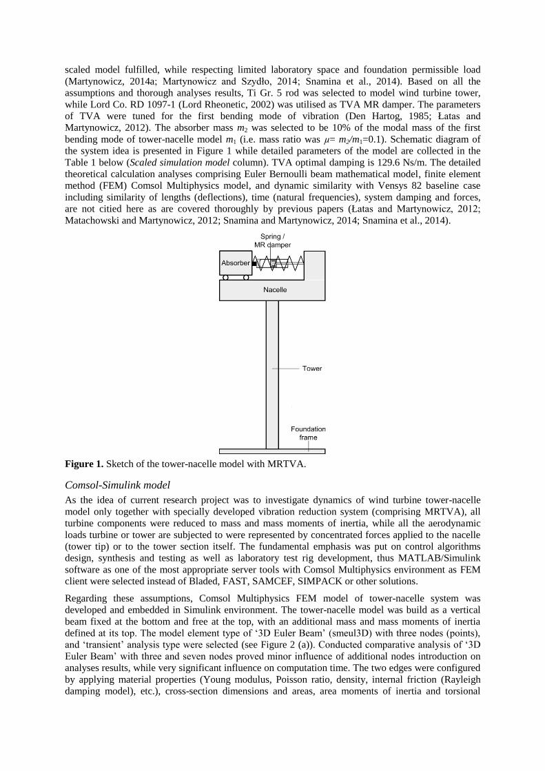
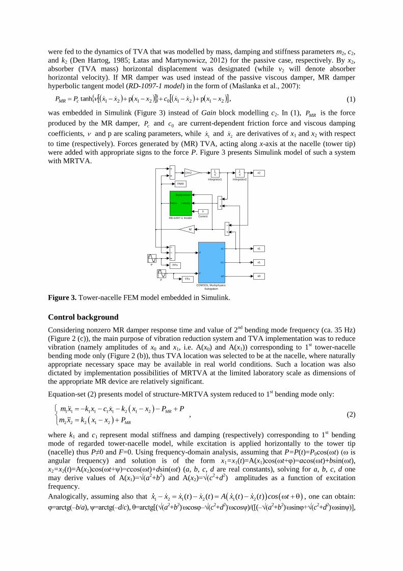
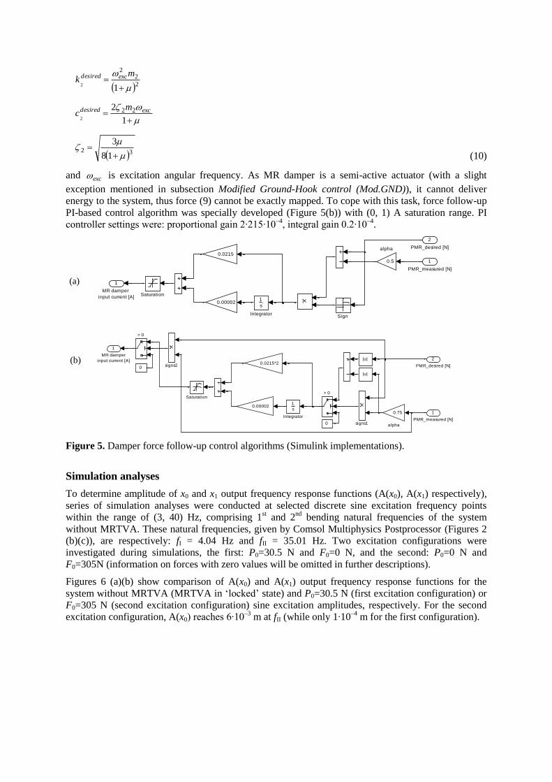
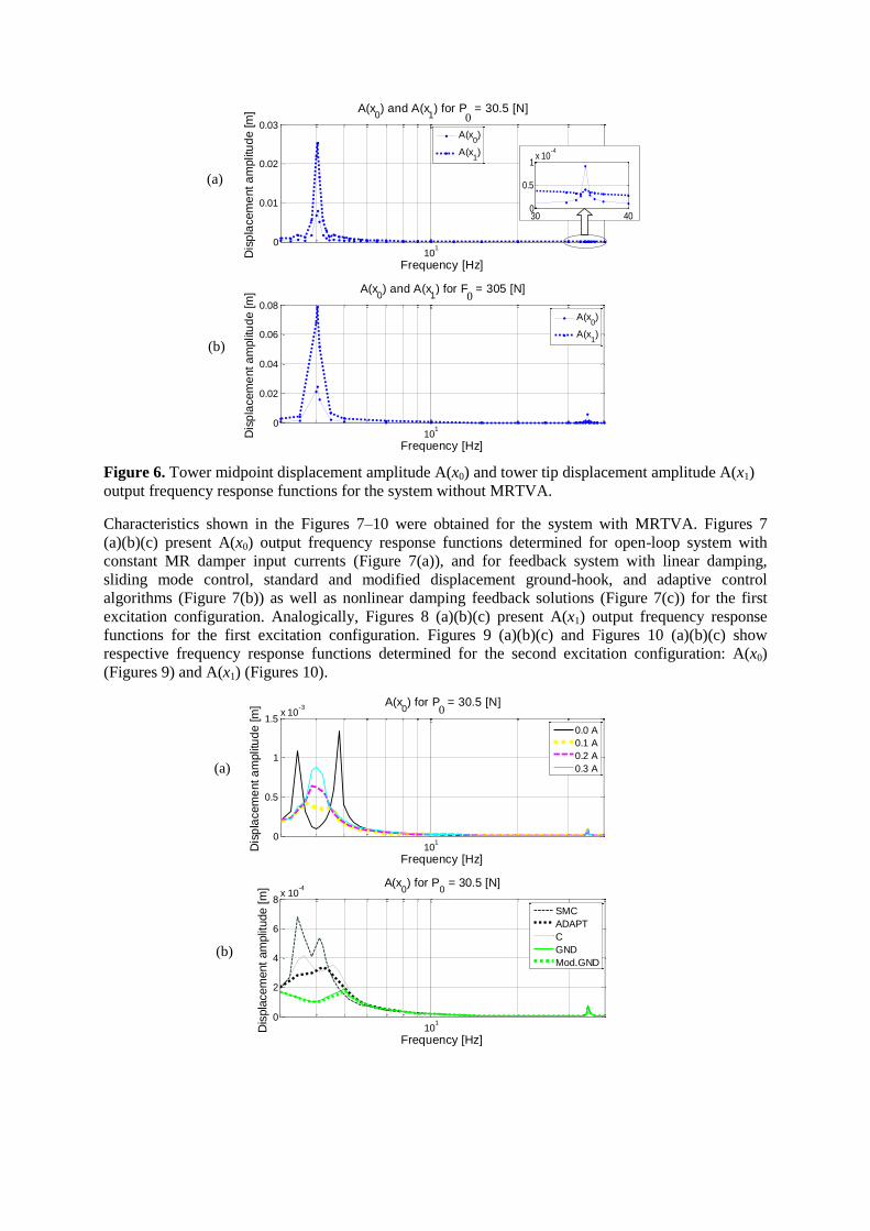
101
0
001
002
003
A(x0) and A(x
1) for P
x = 305 [N]
Frequency [Hz]
Dis
pla
cem
ent a
mplit
ud
e [m
]
A(x0)
A(x1)
101
0
002
004
006
008
A(x0) and A(x
1) for F
x = 305 [N]
Frequency [Hz]
Dis
pla
cem
ent a
mplit
ud
e [m
]
A(x0)
A(x1)
Figure 6 Tower midpoint displacement amplitude A(x0) and tower tip displacement amplitude A(x1)
output frequency response functions for the system without MRTVA
Characteristics shown in the Figures 7ndash10 were obtained for the system with MRTVA Figures 7
(a)(b)(c) present A(x0) output frequency response functions determined for open-loop system with
constant MR damper input currents (Figure 7(a)) and for feedback system with linear damping
sliding mode control standard and modified displacement ground-hook and adaptive control
algorithms (Figure 7(b)) as well as nonlinear damping feedback solutions (Figure 7(c)) for the first
excitation configuration Analogically Figures 8 (a)(b)(c) present A(x1) output frequency response
functions for the first excitation configuration Figures 9 (a)(b)(c) and Figures 10 (a)(b)(c) show
respective frequency response functions determined for the second excitation configuration A(x0)
(Figures 9) and A(x1) (Figures 10)
101
0
05
1
15x 10
-3A(x
0) for P
x = 305 [N]
Frequency [Hz]
Dis
pla
cem
ent a
mplit
ud
e [m
]
00 A
01 A
02 A
03 A
101
0
2
4
6
8x 10
-4A(x
0) for P
0 = 305 [N]
Frequency [Hz]
Dis
pla
cem
ent
am
plit
ude [
m]
SMC
ADAPT
C
GND
ModGND
30 400
05
1x 10
-4
0
0
0
(a)
(b)
(b)
(a)
101
0
1
2
3
4
5x 10
-4A(x
0) for P
x = 305 [N]
Frequency [Hz]D
isp
lacem
ent a
mplit
ud
e [m
]
C3 150
C3 250
SQRT 025
SQRT 03
Figure 7 Tower midpoint displacement amplitude A(x0) output frequency response functions for the
system with MRTVA P0 = 305 N
101
0
1
2
3
4
5x 10
-3A(x
1) for P
x = 305 [N]
Frequency [Hz]
Dis
pla
cem
ent a
mplit
ud
e [m
]
00 A
01A
02A
03 A
10
10
05
1
15
2
25x 10
-3A(x
1) for P
0 = 305 [N]
Frequency [Hz]
Dis
pla
cem
ent
am
plit
ude [
m]
SMC
ADAPT
C
GND
ModGND
101
0
05
1
15x 10
-3A(x
1) for P
x = 305 [N]
Frequency [Hz]
Dis
pla
cem
ent a
mplit
ud
e [m
]
C3 150
C3 250
SQRT 025
SQRT 03
Figure 8 Tower tip displacement amplitude A(x1) output frequency response functions for the system
with MRTVA P0 = 305 N
0
0
0
(c)
(a)
(b)
(c)
101
0
2
4
6x 10
-3A(x
0) for F
x = 305 [N]
Frequency [Hz]D
isp
lacem
ent a
mplit
ud
e [m
]
00A
01A
02A
03A
10
10
2
4
6x 10
-3 A(x0) for F
0 = 305 [N]
Frequency [Hz]
Dis
pla
cem
ent
am
plit
ude [
m]
SMC
C
ADAPT
GND
ModGND
101
0
2
4
6x 10
-3A(x
0) for F
x = 305 [N]
Frequency [Hz]
Dis
pla
cem
ent a
mplit
ud
e [m
]
SQRT 025
C3 50
C3 250
Figure 9 Tower midpoint displacement amplitude A(x0) output frequency response functions for the
system with MRTVA F0 = 305 N
101
0
0005
001
0015
002
A(x1) for F
x = 305 [N]
Frequency [Hz]
Dis
pla
cem
ent a
mplit
ud
e [m
]
00 A
01 A
02 A
03 A
10
10
0005
001
0015
002A(x
1) for F
0 = 305 [N]
Frequency [Hz]
Dis
pla
cem
ent
am
plit
ude [
m]
C
SMC
ADAPTr
GND
ModGND
0
0
0
(a)
(c)
(b)
(b)
(c)
(a)
101
0
2
4
6
8x 10
-3A(x
1) for Fx = 305 [N]
Frequency [Hz]D
isp
lacem
ent a
mplit
ud
e [m
]
SQRT 025
C3 50
C3 250
Figure 10 Tower tip displacement amplitude A(x1) output frequency response functions for the
system with MRTVA F0 = 305 N
The presented results prove the potential of MRTVA in tower-nacelle system vibration reduction at
frequency of the 1st bending mode without deterioration at other frequencies Substitution of passive
TVA with MRTVA enables further vibration reduction by application of dedicated control solutions
Maximum amplitudes obtained with GND and ModGDN control algorithms were in the majority of
simulation scenarios lesser than half of the maximum amplitudes of the system emulating linear
damping as in standard TVA with passive viscous damper (designated by C) The accuracy of passive
damper force follow-up is limited by the actuator nature The advantage of ModGDN algorithm over
GND may be observed eg at frequency of 50 Hz (Figure 7 and Figure 8) MR damper current control
operation is demonstrated by PMR force values switches reflecting control current impulses between
0 and max
MRi Time plots presented in Figures 11 and 12 prove that equation (5) produces more favourable
MR damper control pattern (observed as x1 amplitude reduction) than equation (4) due to hysteresis
phenomenon of MR damper force-velocity characteristics ModGDN algorithm implemented on the
experimental ground in comparison with GND algorithm is presented as a separate publication
(Martynowicz 2015)
1975 198 1985 199 1995
-6
-4
-2
0
2
4
6
Time [s]
Dis
pla
ce
me
nt C
urr
en
t F
orc
e
F0=305 N
x110
4 [m]
(x1-x
2)10
3 [m]
iMR
[A]
PMR
10-1
[N]
Figure 11 Tower tip displacement x1 MR damper travel x1ndashx2 current iMR and force PMR for the
feedback system with GND algorithm F0 = 305 N
1975 198 1985 199 1995
-6
-4
-2
0
2
4
6
Time [s]
Dis
pla
ce
me
nt C
urr
en
t F
orc
e
F0=305 N
x110
4 [m]
(x1-x
2)10
3 [m]
iMR
[A]
PMR
10-1
[N]
Figure 12 Tower tip displacement x1 MR damper travel x1ndashx2 current iMR and force PMR for the
feedback system with ModGND algorithm F0 = 305 N
As depicted above effectiveness of the adaptive control was limited by MR damper semi-active type
of actuation and its force variation range precluding MRTVA possibility to adapt to 2nd
bending mode
(even neglecting MR damper response time) while benefits of ADAPT over standard TVA (ie linear
0
(c)
damping C) are noticeable The ADAPT results are quite on par with most favourable open-loop
system (01 A) results for P0 (tower tip) excitation (Figures 7ndash8) However for F0 (tower midpoint)
excitation of the 1st mode (Figures 9ndash10) ADAPT copes better than 01 A open-loop system and
comparable to 03 A open-loop (which in turn delivers less favourable characteristics than ADAPT for
P0 excitation) Consequently ADAPT algorithm presents better performance than 02 A and 00 A
open-loop systems in all conditions considered Further analyses of ADAPT for system parameters
uncertainty may be planned in the future The sliding mode and nonlinear damping control solutions
deliver no apparent advantage over MRTVA emulating viscous damping C Further analyses are
considered It was also determined that for laboratory model 2nd
bending mode amplitude A(x1) is
relatively small (A(x1) ltlt A(x0)) (see Figure 2 (c) Figures 6 ndash 10) as mass of the nacelle is much
higher than tower mass Moreover regarding MR damper response time and value of 2nd
bending
mode frequency vibration reduction possibilities of MRTVA is very much limited to the 1st bending
mode However in real-world applications nacelle displacement amplitude is meaningful for 2nd
bending mode while its frequency is below 5 Hz thus vibration reduction possibilities of MRTVA
located at the nacelle are there
It is worth to point out that ComsolSimulink co-simulation analyses give the possibilities of testing
various MR damper control algorithms for the continuous-discrete system modelled in FEM
environment however computational load is very significant and time consuming
Validation analyses
The results obtained in the previous section serve as a basis for validation analyses of the regarded
model vs full-scale Vensys 82 wind turbine tower-nacelle baseline structure assuming nacelle and
turbine to be a one solid body (excluding blades aerodynamics) It was previously proven (Snamina and
Martynowicz 2014 Snamina et al 2014) that conditions of partial dynamic similarity (similarity of
motion of tower tips) between regarded model and full-scale structure are fulfilled Now these former
results are verified using FEM model of Vensys 82 tower-nacelle structure embedded (similarly as
presented above) in Simulink environment with MRTVA model and dedicated control algorithm For
these analyses ModGND algorithm was chosen and compared with reference structure without
MRTVA Vensys 82 tower-nacelle structure FEM model was built as 9-segment non-prismatic beam (a
tower) with a solid body mass and mass moments of inertia as a nacelleturbine Additionally modified
configuration is proposed with tower massstiffness reduced by the factor of two thanks to the load
mitigation by utilisation of MRTVA along with proper vibration control algorithm The proposed
modified tower structure is of the same height and external diameter vertical profile as original
structure however wall thickness is ca half of the original one Table 1 presents assumed parameters of
the full-scale structure vs its scaled model and proposed modified structure as well as maximum
bending stress maximum deflection and maximum acceleration values corresponding to 1st bending
mode of vibration neighbourhood Comparison of the configuration with and without MRTVA is
presented for sine horizontal excitation applied to the nacelle (P) for each structure model (for modified
Vensys 82 model variant without MRTVA cannot be considered due to large bending stress values)
For both original and modified Vensys 82 models with MRTVA MR damper force is assumed
according to the conclusion of dynamic similarity analysis (see Snamina and Martynowicz 2014)
Regarding real-world turbine aerodynamic damping preferable TVA operation direction should lie
within the plane parallel to the rotor plane Figures 13 and 14 present tower tip (nacelle) displacement
and acceleration amplitude output frequency response functions for baseline and modified Vensys 82
models with MRTVA and ModGND algorithm assuming P0 = 25103 N
As can be observed in Figures 14 implementation of 65103 kg absorber with appropriate spring and
MR damper selection along with real-time measurement and control system may lead to both structure
overall mass decrease by 78103 kg (or more up to 84510
3 kg assuming that some nacelle
equipmentframe mass may operate in motion ndash as absorber mass) and significant bending loads
deflections and accelerations decrease in comparison with baseline Vensys 82 structure without
MRTVA In case of measurement control MR damper failure internal system watchdog should
execute a switch to a passive regime with zero MR damper current that still provides satisfactory
properties ndash in fact some further MR damper force amplitude ModGND control system tuning
possibilities (leading to further deflections decrease for ModGND system) may be inferred from
ModGND and 00 A curves observation To eliminate (marginally small) risk of MR damper TVA
lock-up failure it may be considered the implementation of both multi-MR-damper TVA system (MR
damper redundancy) and additional passive TVA system with significantly lower absorber mass m2
that is normally-locked (TVA redundancy) ultimate solution would be particular turbine switch off
cut-out within ca 500 seconds (depending on tower steel properties) of resonant vibration when
bending stress value for modified Vensys 82 structure is expected to be similar as maximum bending
stress for baseline Vensys 82 with no TVA according to ComsolSimulink analysis with P0 = 25103 N
Table 1 Assumed models parameters and numerical results validation (1st bending mode neighbourhood)
Model TVA
Parameter
Scaled simulation
model
Baseline Vensys 82
model
Modified Vensys 82
model
no TVA MRTVA no TVA MRTVA no TVA MRTVA
Tower type Prismatic rod Non-prismatic tube Non-prismatic tube
Tower mass [kg] 256 1690103 84510
3
Tower external diameter [m] 007 452 to 330 452 to 330
Tower height [m] 15 850 850
Mass of the assembly located at the
top (nacelle wo absorber) [kg]
1662 1506 904103 77410
3 90410
3 83910
3
Absorber mass [kg] ndash 156 ndash 130103 ndash 6510
3
Mass ratio μ [] ndash 100 ndash 126 ndash 67
TVA spring stiffness [Nm] ndash 952103 ndash 559710
3 ndash 163310
3
Amplitude of horizontal load (P0) [N] 305 25103 2510
3
Results
Maximum displacement [m]
(top end of the tower nacelle)
0079 05510ndash3
306 0048 798 0134
Maximum acceleration [ms2]
(top end of the tower nacelle)
509 0490 150 0263 228 0331
Maximum bending stress [Pa]
(bottom end of the tower)
406106 28210
6 39710
6 68810
6 113010
6 19010
6
10-06
10-05
10-04
10-03
001
002
003
004
005
A(x1) for P
0 = 25
10
3 [N]
Frequency [Hz]
Dis
pla
cem
ent
am
plit
ude [
m]
ModGND
10
-0610
-0510
-0410
-030
01
02
03
Frequency [Hz]Accele
ration a
mplit
ude [
ms
2]
A(x1) for P
0 = 25
10
3 [N]
ModGND
Figure 13 Tower tip displacement amplitude (left) and acceleration amplitude (right) output
frequency response functions for baseline Vensys 82 model with MRTVA (see Table 1)
10-07
10-06
10-05
10-04
0
005
01
015
02
A(x1) for P
0 = 25
10
3 [N]
Frequency [Hz]
Dis
pla
cem
ent
am
plit
ude [
m]
00 A
ModGND
10-07
10-06
10-05
10-04
0
01
02
03
04
05
A(x1) for P
0 = 25
10
3 [N]
Frequency [Hz]Accele
ration a
mplit
ude [
ms
2]
00 A
ModGND
Figure 14 Tower tip displacement amplitude (left) and acceleration amplitude (right) output
frequency response functions for modified Vensys 82 model with MRTVA (see Table 1)
Laboratory test rig
Laboratory test rig of wind turbine tower-nacelle system (Figure 15) was build according to the details specified in the Wind turbine tower-nacelle model section It consists of vertically oriented titanium (Ti Gr5) rod 1 (representing wind-turbine tower) and a set of steel plates 2 (representing nacelle and turbine assemblies) fixed to the top of the rod 1 with MRTVA embedded Titanium rod is rigidly mounted to the steel foundation frame 3 MRTVA 4 is an additional mass moving horizontally along linear bearing guides connected with the assembly representing nacelle via spring and Lord RD 1097-1 MR damper (Lord Rheonetic 2002) in parallel RD 1097-1 damper (which force depends on the current fed to its coil) is an actuator of such a vibration reduction system MRTVA operates along the same direction as vibration excitation applied to the system Force generated by vibration excitation system ie The Modal Shop lightweight electrodynamic force exciter of 2060E series (TMS 2060E) (TMS 2010) 5 with drive train assembly 6 of changeable leverage (enabling changeable force displacement and velocity ranges) may be applied either to the rod 1 (modelling the tower as in the picture) or to the set of steel plates 2 modelling nacelleturbine Excitation signal is generated by LDS Dactron 7 and amplified by TMS 2100E21-400 8
Measurement and control system consists of laser vibrometer (x1) with its controller 9 laser
displacement transducer (x0) 10 LVDT transducer (x1ndash x2) 11 tensometric stress transducers 12 force
(PMR among others) and acceleration transducers (not apparent in the picture) as well as transducers
supplyconditioning system including MR damper signal amplifier 13 and measuring-control PC 14
with MATLABSimulinkRT-CON applications (measured signals designations listed in brackets)
Selected test rig identification results are presented in the Table 2 while full identification problem is
covered by authorrsquos separate publication
Table 2 Selected parameters of laboratory test rig
Length of the rod [10ndash3
m] 1507
Diameter of the rod [10ndash3
m] 705
Mass of the rod [kg] 2606
Mass of the assembly located at the top (nacelle with TVA) [kg] 15535
Figure 15 Laboratory test rig
1
2
4
3
5
6
7
8
9 13
14 10 12
12
11
Laboratory test rig gives the possibility to model wind turbine tower vibration under various excitation sources Moreover the rig may be laid down on the horizontally excited platform to model vibration of buoy-floating wind turbine structures or vibration due to seismic excitation The above mentioned problems are described in detail in separate publications (Martynowicz 2014a Martynowicz and Szydło 2014 Snamina et al 2014)
Laboratory tests
Preliminary laboratory tests results are presented here Initial analyses were conducted with relatively
low excitation amplitudes to assure test facility safe operation The first was excitation test with sine
force of changing frequency (chirp) The force had horizontal direction constant amplitude of 346 N
and was applied to the rod (tower) midpoint (thus F0 = 346 N) Figures 16 (a)(b) present time section
of x0 and x1 displacement response within ca (360 430) Hz range for feedback system with modified
ground-hook (ModGND) control algorithm in comparison with open-loop system (with 00A MR
damper input current) exhibiting lowest x0 and x1 displacement amplitudes The range of (360 430)
Hz comprises 1st tower bending mode of vibration occurring for the system with MRTVA lsquolockedrsquo
(by input current of 06 A) at frequency of 382 Hz that is ca 02 Hz lower than frequency predicted
by Comsol Multiphysics analyses Such a relation between frequencies was predictable as FEM
method imposes the additional stiffness on the model while mass of test rig nacelle with MRTVA is
slightly higher than nacelle mass assumed for FEM model (see Tables 2 and 3) Some differences in
tower theoretical and laboratory model parameters are present too The maximum displacements
amplitudes max(A(x1)) max(A(x0)) and their ratio max(A(x1))max(A(x0)) as well as maximum MR
damper force values for MRTVA system operating in open-loop and feedback modes are all collected
in the Table 3
It is worth to note that MRTVA operating in feedback mode is by a small margin the most effective in
tower deflection x0 and x1 reduction (Table 3 Figures 16) and simultaneously (thanks to displacements
amplitudes minimisation) generates lowest value of maximum MR damper force Maximum
displacements amplitudes ratio values (resulting from the vibration mode shape) variation is
insignificant for selected MR damper input current values however it displays some system
nonlinearities
0 20 40 60-5
0
5x 10
-4
Time [s]
Tow
er
mid
poin
t dis
pla
cem
ent x 0
[m
]
00 A
ModGND
0 20 40 60-2
-1
0
1
2x 10
-3
Time [s]
Tow
er
tip d
ispla
cem
ent x 1
[m
]
00 A
ModGND
Figure 16 Responses of tower-nacelle system under chirp-type excitation
(a)
(b)
Table 3 Results of chirp-type excitation laboratory tests
Configuration Details Open-loop mode Feedback mode
ModGND (Figures 16) 000 A 005 A 010 A 020 A
Max displ ampl
max(A(w0)) [10ndash3
m]
045 047 059 083 039
Max displ ampl
max(A(w1)) [10ndash3
m]
154 167 199 289 138
max(A(w1)) max(A(w0)) 346 353 340 350 351
Max MR Damper Force [N] 300 319 478 887 278
On a ground of these results frequency characteristics were evaluated Figures 17 (a)(b) present A(x0)
and A(x1) output frequency response functions determined at F0 = 305 N excitation within
(3 40) Hz frequency range for the open-loop system with 00 A and 01 A input currents 06 A input
current (ie MRTVA in lsquolockedrsquo state) and feedback system with ModGND algorithm These
characteristics as well as x0 and x1 displacement amplitude values from the Table 3 indicate system is
more damped than simulation model (details in authorrsquos separate paper on test rig identification) The
typical for TVA two maxima cannot be observed in Figures 17 for 00 A as for simulation model All
of that causes control results to be compromised as lowest control signal value of 00 A is
simultaneously the input current providing the best vibration reduction results from among all open-
loop solutions with constant input current (Table 3 Figures 17) in relatively low force excitation
conditions
Following the above results and conclusions the next test was undergone with significantly higher
excitation amplitude within the most interesting 1st bending resonance neighbourhood range Figures
18 (a)(b) present A(x0) and A(x1) output frequency response functions determined at F0 = 150 N
(325 500) Hz excitation conditions for the open-loop system with 00 A input current and feedback
system with ModGND algorithm As can be inferred from Figures 18 (in comparison with Figures
17) MR damper pre-yield force is less dominant at relatively high excitation amplitudes thus some
control possibilities are there in comparison with 00 A open-loop system for which also the two local
maxima are apparent as for the system with standard passive TVA
10
1
2
4
6
8
10
12
x 10-4
Frequency [Hz]
Dis
pla
cem
ent
am
plit
ude [
m]
A(x0) for F
0 = 305 N
00 A
01 A
06 A
ModGND
10
10
05
1
15
2
25x 10
-3
Frequency [Hz]
Dis
pla
cem
ent
am
plit
ude [
m]
A(x1) for F
0 = 305 N
00 A
01 A
06 A
ModGND
Figure 17 Tower midpoint displacement amplitude A(x0) and tower tip displacement amplitude A(x1)
output frequency response functions
(a)
(b)
10
05210
05510
05810
06110
06410
0670
2
4
6
8x 10
-4
Frequency [Hz]
Dis
pla
cem
ent
am
plit
ude [
m] A(x
0) for F
0 = 150 N
00 A
ModGND
10
05210
05510
05810
06110
06410
06705
1
15
2
25x 10
-3
Frequency [Hz]
Dis
pla
cem
ent
am
plit
ude [
m] A(x
1) for F
0 = 150 N
00 A
ModGND
Figure 18 Tower midpoint displacement amplitude A(x0) and tower tip displacement amplitude A(x1)
output frequency response functions
To more completely cope with the problem of too much MRTVA damping test rig was reconfigured
by increasing nacelle and absorber masses as well as stiffness of TVA spring thus increasing damping
ratio (and so MR damper input current) required for optimum (Den Hartog 1985) TVA operation
while maintaining x1 and x2 displacements ranges (the laboratory test rig was designed in such a way
that masses of the nacelle absorber as well as spring stiffness may be changed while MR damper
type change is not considered due to limited market availability) The preliminary results obtained for
the reconfigured system are presented in Figures 19 (a)(b) As can be observed ModGND system
delivers the most favourable response over the regarded (272 472) Hz frequency range as compared
with the passive system with 00 A and 01 A control currents
1005
1006
0
05
1
15x 10
-3
Frequency [Hz]
Dis
pla
cem
ent
am
plit
ude [
m]
A(x0) for F
0 = 150 N
00 A
01 A
ModGND
1005
1006
0
1
2
3
4
5x 10
-3
Frequency [Hz]
Dis
pla
cem
ent
am
plit
ude [
m]
A(x1) for F
0 = 150 N
00 A
01 A
ModGND
Figure 19 Tower midpoint displacement amplitude A(x0) and tower tip displacement amplitude A(x1)
output frequency response functions (after reconfiguration)
(a)
(b)
(a)
(b)
Conclusion
The conducted comprehensive simulation study delivers a lot of valuable data concerning vibration reduction of tower-nacelle model with MRTVA Vibration control results for the system equipped with MRTVA are improved in relation with the system that emulates standard TVA with linear (viscous) damper ComsolSimulink co-simulation tool is a good solution for control algorithms analysis prototyping and implementation for continuous and continuous-discrete systems however computational time is quite a problem
The results of simulation analyses along with calculations concerning dynamic similarity of the proposed model with Vensys 82 real-world wind turbine (Snamina and Martynowicz 2014 Snamina et al 2014) served for estimation of the benefits of implementation of MRTVA for a full-scale structure These include possible reduction of structure overall mass significant reduction of tower deflection (thus bending fatigue) and nacelle acceleration amplitudes as well as possible operation at higher RPM to increase power production and decrease cost of energy factor while reducing risk of structure failure due to wind waves or earthquake induced vibration The cost analysis however is nor subject of current research project
Previous section results proved the laboratory test rig was more damped than simulation model and that compromised control possibilities as minimum control signal for feedback system (00 A) was providing the best vibration reduction results in open-loop case for low excitation amplitudes (F0 = 305 N and F0 = 346 N) To cope with that problem excitation amplitude was increased (F0 = 150 N) and test rig was reconfigured Some preliminary laboratory-based validation results of new laboratory validation tests are presented here while their full scope is covered by the separate papers (Martynowicz 2015 Rosoacuteł and Martynowicz 2015)
Further work program includes wide cooperation on implementation of such designed MRTVA system in the full scale structure within the scope of EU project
Acknowledgment
This work was financed by the Polish National Science Centre project no 2286BT02201140
References
Bak C Bitsche R Yde A Kim T Hansen MH Zahle F Gaunaa M Blasques J Dossing M Wedel-
Heinen JJ and Behrens T (2012) Light Rotor The 10-MW reference wind turbine In European Wind
Energy Association Annual Event 16ndash19042012 Copenhagen Denmark
Butt UA and Ishihara T (2012) Seismic Load Evaluation of Wind Turbine Support Structures
Considering Low Structural Damping and Soil Structure Interaction In European Wind Energy
Association Annual Event 16ndash19042012 Copenhagen Denmark
Den Hartog JP (1985) Mechanical Vibrations Mineola Dover Publications
Enevoldsen I and Mork KJ (1996) Effects of Vibration Mass Damper in a Wind Turbine Tower Mech
Struct amp Mach 24(2) 155ndash187
Hansen MH Fuglsang P Thomsen K and Knudsen T (2012) Two Methods for Estimating Aeroelastic
Damping of Operational Wind Turbine Modes from Experiments In European Wind Energy
Association Annual Event 16ndash19042012 Copenhagen Denmark
Jain P (2011) Wind Energy Engineering McGRAW-HILL
Jelavić M Perić N and Petrović I (2007) Damping of Wind Turbine Tower Oscillations through Rotor
Speed Control In International Conference on Ecologic Vehicles amp Renewable Energies March 29ndash
April 1 2007 Monaco
Kciuk S and Martynowicz P (2011) Special application magnetorheological valve numerical and
experimental analysis Control engineering in materials processing Diffusion and Defect Data ndash Solid
State Data Pt B Solid State Phenomena Vol 177 102ndash115
Kirkegaard PH Nielsen SRK Poulsen BL Andersen J Pedersen LH and Pedersen BJ (2002)
Semiactive vibration control of a wind turbine tower using an MR damper In Grundmann H and
Schueller GI (eds) Struct Dynamics EURODYN Lisse Swets amp Zeitlinger
Koo JH and Ahmadian M (2007) Qualitative Analysis of Magneto-Rheological Tuned Vibration
Absorbers Experimental Approach Journal of Intelligent Material Systems and Structures Vol 18
December 2007
Laalej H Lang ZQ Sapinski B and Martynowicz P (2012) MR damper based implementation of
nonlinear damping for a pitch plane suspension system Smart Materials and Structures Vol 21
Lord Rheonetic (2002) MR Controllable Friction Damper RD-1097-01 Product Bulletin
Łatas W and Martynowicz P (2012) Modelowanie drgań układu maszt-gondola elektrowni wiatrowej
z tłumikiem dynamicznym Modelowanie Inżynierskie nr 44 t 13 187ndash198
Martynowicz P (2014a) Development of Laboratory Model of Wind Turbines Tower-Nacelle System
with Magnetorheological Tuned Vibration Absorber Solid State Phenomena Vol 208 40ndash51
Martynowicz P (2014b) Wind turbines tower-nacelle model with magnetorheological tuned vibration
absorber ndash numerical and experimental analysis In 6WCSCM Sixth World Conference on Structural
Control and Monitoring ndash proceedings of the 6th edition of the World conference of the International
Association for Structural Control and Monitoring (IACSM) Barcelona Spain 15ndash17 July 2014
Martynowicz P (2015) Study of vibration control using laboratory test rig of wind turbinersquos tower-
nacelle system with MR damper based tuned vibration absorber Bulletin of the Polish Academy of
Sciences Technical Sciences (in review)
Martynowicz P and Szydło Z (2013) Wind turbines tower-nacelle model with magnetorheological
tuned vibration absorber the laboratory test rig In Proceedings of the 14th International Carpathian
Control Conference (ICCC) Rytro Poland May 26ndash29 2013
Maślanka M Sapiński B and Snamina J (2007) Experimental Study of Vibration Control of a Cable
With an Attached MR Damper Journal of Theoretical and Applied Mechanics 45 4 893ndash917
Warsaw
Matachowski F and Martynowicz P (2012) Analiza dynamiki konstrukcji elektrowni wiatrowej z
wykorzystaniem środowiska Comsol Multiphysics Modelowanie Inżynierskie nr 44 t 13 209ndash216
Namik H and Stol K (2011) Performance analysis of individual blade pitch control of offshore wind
turbines on two floating platforms Mechatronics 21 691ndash703
Neelakantan VA and Washington GN (2008) Vibration Control of Structural Systems using MR
dampers and a lsquoModifiedrsquo Sliding Mode Control Technique Journal of Intelligent Material Systems
and Structures Vol 19
Oh S and Ishihara T (2013) A Study on Structure Parameters of an Offshore Wind Turbine by
Excitation test Using Active Mass Damper In EWEA Offshore 19-21112013 Frankfurt
Rosoacuteł M and Martynowicz P (2015) Identification of Laboratory Model of Wind Turbinersquos Tower-
Nacelle System with MR Damper Based Tuned Vibration Absorber Mechanical Systems and Signal
Processing (in review)
Rotea MA Lackner MA and Saheba R (2010) Active Structural Control of Offshore Wind turbines
In 48th AIAA Aerospace Sciences Meeting Including the New Horizons Forum and Aerospace
Exposition 4ndash7 January 2010 Orlando Florida
Sapiński B (2008) Real-time control of magnetorheological dampers in mechanical systems Cracow
AGH University of Science and Technology Press
Sapiński B and Rosoacuteł M (2008) Autonomous control system for a 3 DOF pitch-plane suspension
system with MR shock absorbers Computers and Structures 86 379ndash385
Sapiński B (2011) Experimental study of a self-powered and sensing MR damper-based vibration
control system Smart Materials and Structures 20 105007
Shan W and Shan M (2012) Gain Scheduling Pitch Control Design for Active Tower Damping and 3p
Harmonic Reduction In European Wind Energy Association Annual Event 16ndash19042012
Copenhagen Denmark
Shen YJ Wang L Yang SP and Gao GS (2013) Nonlinear dynamical analysis and parameters
optimization of four semi-active on-off dynamic vibration absorbers Journal of Vibration and
Control January 2013 vol 19 no 1 143ndash160
Snamina J Martynowicz P and Łatas W (2014) Dynamic similarity of wind turbinersquos tower-nacelle
system and its scaled model Solid State Phenomena Vol 208 29ndash39
Snamina J and Martynowicz P (2014) Prediction of characteristics of wind turbines tower-nacelle
system from investigation of its scaled model In 6WCSCM Sixth World Conference on Structural
Control and Monitoring ndash proceedings of the 6th edition of the World conference of the International
Association for Structural Control and Monitoring (IACSM) Barcelona Spain 15ndash17 July 2014
TMS (2010) 60 Lbf Modal Shaker The Modal Shop Inc
Tsouroukdissian A Carcangiu CE Pineda Amo I Martin M Fischer T Kuhnle B and Scheu M
(2011) Wind Turbine Tower Load Reduction using Passive and Semiactive Dampers European Wind
Energy Association Annual Event Brussels
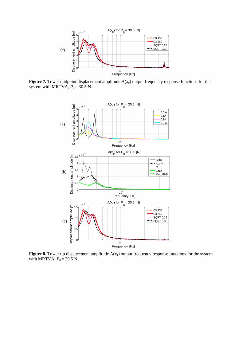
101
0
1
2
3
4
5x 10
-4A(x
0) for P
x = 305 [N]
Frequency [Hz]D
isp
lacem
ent a
mplit
ud
e [m
]
C3 150
C3 250
SQRT 025
SQRT 03
Figure 7 Tower midpoint displacement amplitude A(x0) output frequency response functions for the
system with MRTVA P0 = 305 N
101
0
1
2
3
4
5x 10
-3A(x
1) for P
x = 305 [N]
Frequency [Hz]
Dis
pla
cem
ent a
mplit
ud
e [m
]
00 A
01A
02A
03 A
10
10
05
1
15
2
25x 10
-3A(x
1) for P
0 = 305 [N]
Frequency [Hz]
Dis
pla
cem
ent
am
plit
ude [
m]
SMC
ADAPT
C
GND
ModGND
101
0
05
1
15x 10
-3A(x
1) for P
x = 305 [N]
Frequency [Hz]
Dis
pla
cem
ent a
mplit
ud
e [m
]
C3 150
C3 250
SQRT 025
SQRT 03
Figure 8 Tower tip displacement amplitude A(x1) output frequency response functions for the system
with MRTVA P0 = 305 N
0
0
0
(c)
(a)
(b)
(c)
101
0
2
4
6x 10
-3A(x
0) for F
x = 305 [N]
Frequency [Hz]D
isp
lacem
ent a
mplit
ud
e [m
]
00A
01A
02A
03A
10
10
2
4
6x 10
-3 A(x0) for F
0 = 305 [N]
Frequency [Hz]
Dis
pla
cem
ent
am
plit
ude [
m]
SMC
C
ADAPT
GND
ModGND
101
0
2
4
6x 10
-3A(x
0) for F
x = 305 [N]
Frequency [Hz]
Dis
pla
cem
ent a
mplit
ud
e [m
]
SQRT 025
C3 50
C3 250
Figure 9 Tower midpoint displacement amplitude A(x0) output frequency response functions for the
system with MRTVA F0 = 305 N
101
0
0005
001
0015
002
A(x1) for F
x = 305 [N]
Frequency [Hz]
Dis
pla
cem
ent a
mplit
ud
e [m
]
00 A
01 A
02 A
03 A
10
10
0005
001
0015
002A(x
1) for F
0 = 305 [N]
Frequency [Hz]
Dis
pla
cem
ent
am
plit
ude [
m]
C
SMC
ADAPTr
GND
ModGND
0
0
0
(a)
(c)
(b)
(b)
(c)
(a)
101
0
2
4
6
8x 10
-3A(x
1) for Fx = 305 [N]
Frequency [Hz]D
isp
lacem
ent a
mplit
ud
e [m
]
SQRT 025
C3 50
C3 250
Figure 10 Tower tip displacement amplitude A(x1) output frequency response functions for the
system with MRTVA F0 = 305 N
The presented results prove the potential of MRTVA in tower-nacelle system vibration reduction at
frequency of the 1st bending mode without deterioration at other frequencies Substitution of passive
TVA with MRTVA enables further vibration reduction by application of dedicated control solutions
Maximum amplitudes obtained with GND and ModGDN control algorithms were in the majority of
simulation scenarios lesser than half of the maximum amplitudes of the system emulating linear
damping as in standard TVA with passive viscous damper (designated by C) The accuracy of passive
damper force follow-up is limited by the actuator nature The advantage of ModGDN algorithm over
GND may be observed eg at frequency of 50 Hz (Figure 7 and Figure 8) MR damper current control
operation is demonstrated by PMR force values switches reflecting control current impulses between
0 and max
MRi Time plots presented in Figures 11 and 12 prove that equation (5) produces more favourable
MR damper control pattern (observed as x1 amplitude reduction) than equation (4) due to hysteresis
phenomenon of MR damper force-velocity characteristics ModGDN algorithm implemented on the
experimental ground in comparison with GND algorithm is presented as a separate publication
(Martynowicz 2015)
1975 198 1985 199 1995
-6
-4
-2
0
2
4
6
Time [s]
Dis
pla
ce
me
nt C
urr
en
t F
orc
e
F0=305 N
x110
4 [m]
(x1-x
2)10
3 [m]
iMR
[A]
PMR
10-1
[N]
Figure 11 Tower tip displacement x1 MR damper travel x1ndashx2 current iMR and force PMR for the
feedback system with GND algorithm F0 = 305 N
1975 198 1985 199 1995
-6
-4
-2
0
2
4
6
Time [s]
Dis
pla
ce
me
nt C
urr
en
t F
orc
e
F0=305 N
x110
4 [m]
(x1-x
2)10
3 [m]
iMR
[A]
PMR
10-1
[N]
Figure 12 Tower tip displacement x1 MR damper travel x1ndashx2 current iMR and force PMR for the
feedback system with ModGND algorithm F0 = 305 N
As depicted above effectiveness of the adaptive control was limited by MR damper semi-active type
of actuation and its force variation range precluding MRTVA possibility to adapt to 2nd
bending mode
(even neglecting MR damper response time) while benefits of ADAPT over standard TVA (ie linear
0
(c)
damping C) are noticeable The ADAPT results are quite on par with most favourable open-loop
system (01 A) results for P0 (tower tip) excitation (Figures 7ndash8) However for F0 (tower midpoint)
excitation of the 1st mode (Figures 9ndash10) ADAPT copes better than 01 A open-loop system and
comparable to 03 A open-loop (which in turn delivers less favourable characteristics than ADAPT for
P0 excitation) Consequently ADAPT algorithm presents better performance than 02 A and 00 A
open-loop systems in all conditions considered Further analyses of ADAPT for system parameters
uncertainty may be planned in the future The sliding mode and nonlinear damping control solutions
deliver no apparent advantage over MRTVA emulating viscous damping C Further analyses are
considered It was also determined that for laboratory model 2nd
bending mode amplitude A(x1) is
relatively small (A(x1) ltlt A(x0)) (see Figure 2 (c) Figures 6 ndash 10) as mass of the nacelle is much
higher than tower mass Moreover regarding MR damper response time and value of 2nd
bending
mode frequency vibration reduction possibilities of MRTVA is very much limited to the 1st bending
mode However in real-world applications nacelle displacement amplitude is meaningful for 2nd
bending mode while its frequency is below 5 Hz thus vibration reduction possibilities of MRTVA
located at the nacelle are there
It is worth to point out that ComsolSimulink co-simulation analyses give the possibilities of testing
various MR damper control algorithms for the continuous-discrete system modelled in FEM
environment however computational load is very significant and time consuming
Validation analyses
The results obtained in the previous section serve as a basis for validation analyses of the regarded
model vs full-scale Vensys 82 wind turbine tower-nacelle baseline structure assuming nacelle and
turbine to be a one solid body (excluding blades aerodynamics) It was previously proven (Snamina and
Martynowicz 2014 Snamina et al 2014) that conditions of partial dynamic similarity (similarity of
motion of tower tips) between regarded model and full-scale structure are fulfilled Now these former
results are verified using FEM model of Vensys 82 tower-nacelle structure embedded (similarly as
presented above) in Simulink environment with MRTVA model and dedicated control algorithm For
these analyses ModGND algorithm was chosen and compared with reference structure without
MRTVA Vensys 82 tower-nacelle structure FEM model was built as 9-segment non-prismatic beam (a
tower) with a solid body mass and mass moments of inertia as a nacelleturbine Additionally modified
configuration is proposed with tower massstiffness reduced by the factor of two thanks to the load
mitigation by utilisation of MRTVA along with proper vibration control algorithm The proposed
modified tower structure is of the same height and external diameter vertical profile as original
structure however wall thickness is ca half of the original one Table 1 presents assumed parameters of
the full-scale structure vs its scaled model and proposed modified structure as well as maximum
bending stress maximum deflection and maximum acceleration values corresponding to 1st bending
mode of vibration neighbourhood Comparison of the configuration with and without MRTVA is
presented for sine horizontal excitation applied to the nacelle (P) for each structure model (for modified
Vensys 82 model variant without MRTVA cannot be considered due to large bending stress values)
For both original and modified Vensys 82 models with MRTVA MR damper force is assumed
according to the conclusion of dynamic similarity analysis (see Snamina and Martynowicz 2014)
Regarding real-world turbine aerodynamic damping preferable TVA operation direction should lie
within the plane parallel to the rotor plane Figures 13 and 14 present tower tip (nacelle) displacement
and acceleration amplitude output frequency response functions for baseline and modified Vensys 82
models with MRTVA and ModGND algorithm assuming P0 = 25103 N
As can be observed in Figures 14 implementation of 65103 kg absorber with appropriate spring and
MR damper selection along with real-time measurement and control system may lead to both structure
overall mass decrease by 78103 kg (or more up to 84510
3 kg assuming that some nacelle
equipmentframe mass may operate in motion ndash as absorber mass) and significant bending loads
deflections and accelerations decrease in comparison with baseline Vensys 82 structure without
MRTVA In case of measurement control MR damper failure internal system watchdog should
execute a switch to a passive regime with zero MR damper current that still provides satisfactory
properties ndash in fact some further MR damper force amplitude ModGND control system tuning
possibilities (leading to further deflections decrease for ModGND system) may be inferred from
ModGND and 00 A curves observation To eliminate (marginally small) risk of MR damper TVA
lock-up failure it may be considered the implementation of both multi-MR-damper TVA system (MR
damper redundancy) and additional passive TVA system with significantly lower absorber mass m2
that is normally-locked (TVA redundancy) ultimate solution would be particular turbine switch off
cut-out within ca 500 seconds (depending on tower steel properties) of resonant vibration when
bending stress value for modified Vensys 82 structure is expected to be similar as maximum bending
stress for baseline Vensys 82 with no TVA according to ComsolSimulink analysis with P0 = 25103 N
Table 1 Assumed models parameters and numerical results validation (1st bending mode neighbourhood)
Model TVA
Parameter
Scaled simulation
model
Baseline Vensys 82
model
Modified Vensys 82
model
no TVA MRTVA no TVA MRTVA no TVA MRTVA
Tower type Prismatic rod Non-prismatic tube Non-prismatic tube
Tower mass [kg] 256 1690103 84510
3
Tower external diameter [m] 007 452 to 330 452 to 330
Tower height [m] 15 850 850
Mass of the assembly located at the
top (nacelle wo absorber) [kg]
1662 1506 904103 77410
3 90410
3 83910
3
Absorber mass [kg] ndash 156 ndash 130103 ndash 6510
3
Mass ratio μ [] ndash 100 ndash 126 ndash 67
TVA spring stiffness [Nm] ndash 952103 ndash 559710
3 ndash 163310
3
Amplitude of horizontal load (P0) [N] 305 25103 2510
3
Results
Maximum displacement [m]
(top end of the tower nacelle)
0079 05510ndash3
306 0048 798 0134
Maximum acceleration [ms2]
(top end of the tower nacelle)
509 0490 150 0263 228 0331
Maximum bending stress [Pa]
(bottom end of the tower)
406106 28210
6 39710
6 68810
6 113010
6 19010
6
10-06
10-05
10-04
10-03
001
002
003
004
005
A(x1) for P
0 = 25
10
3 [N]
Frequency [Hz]
Dis
pla
cem
ent
am
plit
ude [
m]
ModGND
10
-0610
-0510
-0410
-030
01
02
03
Frequency [Hz]Accele
ration a
mplit
ude [
ms
2]
A(x1) for P
0 = 25
10
3 [N]
ModGND
Figure 13 Tower tip displacement amplitude (left) and acceleration amplitude (right) output
frequency response functions for baseline Vensys 82 model with MRTVA (see Table 1)
10-07
10-06
10-05
10-04
0
005
01
015
02
A(x1) for P
0 = 25
10
3 [N]
Frequency [Hz]
Dis
pla
cem
ent
am
plit
ude [
m]
00 A
ModGND
10-07
10-06
10-05
10-04
0
01
02
03
04
05
A(x1) for P
0 = 25
10
3 [N]
Frequency [Hz]Accele
ration a
mplit
ude [
ms
2]
00 A
ModGND
Figure 14 Tower tip displacement amplitude (left) and acceleration amplitude (right) output
frequency response functions for modified Vensys 82 model with MRTVA (see Table 1)
Laboratory test rig
Laboratory test rig of wind turbine tower-nacelle system (Figure 15) was build according to the details specified in the Wind turbine tower-nacelle model section It consists of vertically oriented titanium (Ti Gr5) rod 1 (representing wind-turbine tower) and a set of steel plates 2 (representing nacelle and turbine assemblies) fixed to the top of the rod 1 with MRTVA embedded Titanium rod is rigidly mounted to the steel foundation frame 3 MRTVA 4 is an additional mass moving horizontally along linear bearing guides connected with the assembly representing nacelle via spring and Lord RD 1097-1 MR damper (Lord Rheonetic 2002) in parallel RD 1097-1 damper (which force depends on the current fed to its coil) is an actuator of such a vibration reduction system MRTVA operates along the same direction as vibration excitation applied to the system Force generated by vibration excitation system ie The Modal Shop lightweight electrodynamic force exciter of 2060E series (TMS 2060E) (TMS 2010) 5 with drive train assembly 6 of changeable leverage (enabling changeable force displacement and velocity ranges) may be applied either to the rod 1 (modelling the tower as in the picture) or to the set of steel plates 2 modelling nacelleturbine Excitation signal is generated by LDS Dactron 7 and amplified by TMS 2100E21-400 8
Measurement and control system consists of laser vibrometer (x1) with its controller 9 laser
displacement transducer (x0) 10 LVDT transducer (x1ndash x2) 11 tensometric stress transducers 12 force
(PMR among others) and acceleration transducers (not apparent in the picture) as well as transducers
supplyconditioning system including MR damper signal amplifier 13 and measuring-control PC 14
with MATLABSimulinkRT-CON applications (measured signals designations listed in brackets)
Selected test rig identification results are presented in the Table 2 while full identification problem is
covered by authorrsquos separate publication
Table 2 Selected parameters of laboratory test rig
Length of the rod [10ndash3
m] 1507
Diameter of the rod [10ndash3
m] 705
Mass of the rod [kg] 2606
Mass of the assembly located at the top (nacelle with TVA) [kg] 15535
Figure 15 Laboratory test rig
1
2
4
3
5
6
7
8
9 13
14 10 12
12
11
Laboratory test rig gives the possibility to model wind turbine tower vibration under various excitation sources Moreover the rig may be laid down on the horizontally excited platform to model vibration of buoy-floating wind turbine structures or vibration due to seismic excitation The above mentioned problems are described in detail in separate publications (Martynowicz 2014a Martynowicz and Szydło 2014 Snamina et al 2014)
Laboratory tests
Preliminary laboratory tests results are presented here Initial analyses were conducted with relatively
low excitation amplitudes to assure test facility safe operation The first was excitation test with sine
force of changing frequency (chirp) The force had horizontal direction constant amplitude of 346 N
and was applied to the rod (tower) midpoint (thus F0 = 346 N) Figures 16 (a)(b) present time section
of x0 and x1 displacement response within ca (360 430) Hz range for feedback system with modified
ground-hook (ModGND) control algorithm in comparison with open-loop system (with 00A MR
damper input current) exhibiting lowest x0 and x1 displacement amplitudes The range of (360 430)
Hz comprises 1st tower bending mode of vibration occurring for the system with MRTVA lsquolockedrsquo
(by input current of 06 A) at frequency of 382 Hz that is ca 02 Hz lower than frequency predicted
by Comsol Multiphysics analyses Such a relation between frequencies was predictable as FEM
method imposes the additional stiffness on the model while mass of test rig nacelle with MRTVA is
slightly higher than nacelle mass assumed for FEM model (see Tables 2 and 3) Some differences in
tower theoretical and laboratory model parameters are present too The maximum displacements
amplitudes max(A(x1)) max(A(x0)) and their ratio max(A(x1))max(A(x0)) as well as maximum MR
damper force values for MRTVA system operating in open-loop and feedback modes are all collected
in the Table 3
It is worth to note that MRTVA operating in feedback mode is by a small margin the most effective in
tower deflection x0 and x1 reduction (Table 3 Figures 16) and simultaneously (thanks to displacements
amplitudes minimisation) generates lowest value of maximum MR damper force Maximum
displacements amplitudes ratio values (resulting from the vibration mode shape) variation is
insignificant for selected MR damper input current values however it displays some system
nonlinearities
0 20 40 60-5
0
5x 10
-4
Time [s]
Tow
er
mid
poin
t dis
pla
cem
ent x 0
[m
]
00 A
ModGND
0 20 40 60-2
-1
0
1
2x 10
-3
Time [s]
Tow
er
tip d
ispla
cem
ent x 1
[m
]
00 A
ModGND
Figure 16 Responses of tower-nacelle system under chirp-type excitation
(a)
(b)
Table 3 Results of chirp-type excitation laboratory tests
Configuration Details Open-loop mode Feedback mode
ModGND (Figures 16) 000 A 005 A 010 A 020 A
Max displ ampl
max(A(w0)) [10ndash3
m]
045 047 059 083 039
Max displ ampl
max(A(w1)) [10ndash3
m]
154 167 199 289 138
max(A(w1)) max(A(w0)) 346 353 340 350 351
Max MR Damper Force [N] 300 319 478 887 278
On a ground of these results frequency characteristics were evaluated Figures 17 (a)(b) present A(x0)
and A(x1) output frequency response functions determined at F0 = 305 N excitation within
(3 40) Hz frequency range for the open-loop system with 00 A and 01 A input currents 06 A input
current (ie MRTVA in lsquolockedrsquo state) and feedback system with ModGND algorithm These
characteristics as well as x0 and x1 displacement amplitude values from the Table 3 indicate system is
more damped than simulation model (details in authorrsquos separate paper on test rig identification) The
typical for TVA two maxima cannot be observed in Figures 17 for 00 A as for simulation model All
of that causes control results to be compromised as lowest control signal value of 00 A is
simultaneously the input current providing the best vibration reduction results from among all open-
loop solutions with constant input current (Table 3 Figures 17) in relatively low force excitation
conditions
Following the above results and conclusions the next test was undergone with significantly higher
excitation amplitude within the most interesting 1st bending resonance neighbourhood range Figures
18 (a)(b) present A(x0) and A(x1) output frequency response functions determined at F0 = 150 N
(325 500) Hz excitation conditions for the open-loop system with 00 A input current and feedback
system with ModGND algorithm As can be inferred from Figures 18 (in comparison with Figures
17) MR damper pre-yield force is less dominant at relatively high excitation amplitudes thus some
control possibilities are there in comparison with 00 A open-loop system for which also the two local
maxima are apparent as for the system with standard passive TVA
10
1
2
4
6
8
10
12
x 10-4
Frequency [Hz]
Dis
pla
cem
ent
am
plit
ude [
m]
A(x0) for F
0 = 305 N
00 A
01 A
06 A
ModGND
10
10
05
1
15
2
25x 10
-3
Frequency [Hz]
Dis
pla
cem
ent
am
plit
ude [
m]
A(x1) for F
0 = 305 N
00 A
01 A
06 A
ModGND
Figure 17 Tower midpoint displacement amplitude A(x0) and tower tip displacement amplitude A(x1)
output frequency response functions
(a)
(b)
10
05210
05510
05810
06110
06410
0670
2
4
6
8x 10
-4
Frequency [Hz]
Dis
pla
cem
ent
am
plit
ude [
m] A(x
0) for F
0 = 150 N
00 A
ModGND
10
05210
05510
05810
06110
06410
06705
1
15
2
25x 10
-3
Frequency [Hz]
Dis
pla
cem
ent
am
plit
ude [
m] A(x
1) for F
0 = 150 N
00 A
ModGND
Figure 18 Tower midpoint displacement amplitude A(x0) and tower tip displacement amplitude A(x1)
output frequency response functions
To more completely cope with the problem of too much MRTVA damping test rig was reconfigured
by increasing nacelle and absorber masses as well as stiffness of TVA spring thus increasing damping
ratio (and so MR damper input current) required for optimum (Den Hartog 1985) TVA operation
while maintaining x1 and x2 displacements ranges (the laboratory test rig was designed in such a way
that masses of the nacelle absorber as well as spring stiffness may be changed while MR damper
type change is not considered due to limited market availability) The preliminary results obtained for
the reconfigured system are presented in Figures 19 (a)(b) As can be observed ModGND system
delivers the most favourable response over the regarded (272 472) Hz frequency range as compared
with the passive system with 00 A and 01 A control currents
1005
1006
0
05
1
15x 10
-3
Frequency [Hz]
Dis
pla
cem
ent
am
plit
ude [
m]
A(x0) for F
0 = 150 N
00 A
01 A
ModGND
1005
1006
0
1
2
3
4
5x 10
-3
Frequency [Hz]
Dis
pla
cem
ent
am
plit
ude [
m]
A(x1) for F
0 = 150 N
00 A
01 A
ModGND
Figure 19 Tower midpoint displacement amplitude A(x0) and tower tip displacement amplitude A(x1)
output frequency response functions (after reconfiguration)
(a)
(b)
(a)
(b)
Conclusion
The conducted comprehensive simulation study delivers a lot of valuable data concerning vibration reduction of tower-nacelle model with MRTVA Vibration control results for the system equipped with MRTVA are improved in relation with the system that emulates standard TVA with linear (viscous) damper ComsolSimulink co-simulation tool is a good solution for control algorithms analysis prototyping and implementation for continuous and continuous-discrete systems however computational time is quite a problem
The results of simulation analyses along with calculations concerning dynamic similarity of the proposed model with Vensys 82 real-world wind turbine (Snamina and Martynowicz 2014 Snamina et al 2014) served for estimation of the benefits of implementation of MRTVA for a full-scale structure These include possible reduction of structure overall mass significant reduction of tower deflection (thus bending fatigue) and nacelle acceleration amplitudes as well as possible operation at higher RPM to increase power production and decrease cost of energy factor while reducing risk of structure failure due to wind waves or earthquake induced vibration The cost analysis however is nor subject of current research project
Previous section results proved the laboratory test rig was more damped than simulation model and that compromised control possibilities as minimum control signal for feedback system (00 A) was providing the best vibration reduction results in open-loop case for low excitation amplitudes (F0 = 305 N and F0 = 346 N) To cope with that problem excitation amplitude was increased (F0 = 150 N) and test rig was reconfigured Some preliminary laboratory-based validation results of new laboratory validation tests are presented here while their full scope is covered by the separate papers (Martynowicz 2015 Rosoacuteł and Martynowicz 2015)
Further work program includes wide cooperation on implementation of such designed MRTVA system in the full scale structure within the scope of EU project
Acknowledgment
This work was financed by the Polish National Science Centre project no 2286BT02201140
References
Bak C Bitsche R Yde A Kim T Hansen MH Zahle F Gaunaa M Blasques J Dossing M Wedel-
Heinen JJ and Behrens T (2012) Light Rotor The 10-MW reference wind turbine In European Wind
Energy Association Annual Event 16ndash19042012 Copenhagen Denmark
Butt UA and Ishihara T (2012) Seismic Load Evaluation of Wind Turbine Support Structures
Considering Low Structural Damping and Soil Structure Interaction In European Wind Energy
Association Annual Event 16ndash19042012 Copenhagen Denmark
Den Hartog JP (1985) Mechanical Vibrations Mineola Dover Publications
Enevoldsen I and Mork KJ (1996) Effects of Vibration Mass Damper in a Wind Turbine Tower Mech
Struct amp Mach 24(2) 155ndash187
Hansen MH Fuglsang P Thomsen K and Knudsen T (2012) Two Methods for Estimating Aeroelastic
Damping of Operational Wind Turbine Modes from Experiments In European Wind Energy
Association Annual Event 16ndash19042012 Copenhagen Denmark
Jain P (2011) Wind Energy Engineering McGRAW-HILL
Jelavić M Perić N and Petrović I (2007) Damping of Wind Turbine Tower Oscillations through Rotor
Speed Control In International Conference on Ecologic Vehicles amp Renewable Energies March 29ndash
April 1 2007 Monaco
Kciuk S and Martynowicz P (2011) Special application magnetorheological valve numerical and
experimental analysis Control engineering in materials processing Diffusion and Defect Data ndash Solid
State Data Pt B Solid State Phenomena Vol 177 102ndash115
Kirkegaard PH Nielsen SRK Poulsen BL Andersen J Pedersen LH and Pedersen BJ (2002)
Semiactive vibration control of a wind turbine tower using an MR damper In Grundmann H and
Schueller GI (eds) Struct Dynamics EURODYN Lisse Swets amp Zeitlinger
Koo JH and Ahmadian M (2007) Qualitative Analysis of Magneto-Rheological Tuned Vibration
Absorbers Experimental Approach Journal of Intelligent Material Systems and Structures Vol 18
December 2007
Laalej H Lang ZQ Sapinski B and Martynowicz P (2012) MR damper based implementation of
nonlinear damping for a pitch plane suspension system Smart Materials and Structures Vol 21
Lord Rheonetic (2002) MR Controllable Friction Damper RD-1097-01 Product Bulletin
Łatas W and Martynowicz P (2012) Modelowanie drgań układu maszt-gondola elektrowni wiatrowej
z tłumikiem dynamicznym Modelowanie Inżynierskie nr 44 t 13 187ndash198
Martynowicz P (2014a) Development of Laboratory Model of Wind Turbines Tower-Nacelle System
with Magnetorheological Tuned Vibration Absorber Solid State Phenomena Vol 208 40ndash51
Martynowicz P (2014b) Wind turbines tower-nacelle model with magnetorheological tuned vibration
absorber ndash numerical and experimental analysis In 6WCSCM Sixth World Conference on Structural
Control and Monitoring ndash proceedings of the 6th edition of the World conference of the International
Association for Structural Control and Monitoring (IACSM) Barcelona Spain 15ndash17 July 2014
Martynowicz P (2015) Study of vibration control using laboratory test rig of wind turbinersquos tower-
nacelle system with MR damper based tuned vibration absorber Bulletin of the Polish Academy of
Sciences Technical Sciences (in review)
Martynowicz P and Szydło Z (2013) Wind turbines tower-nacelle model with magnetorheological
tuned vibration absorber the laboratory test rig In Proceedings of the 14th International Carpathian
Control Conference (ICCC) Rytro Poland May 26ndash29 2013
Maślanka M Sapiński B and Snamina J (2007) Experimental Study of Vibration Control of a Cable
With an Attached MR Damper Journal of Theoretical and Applied Mechanics 45 4 893ndash917
Warsaw
Matachowski F and Martynowicz P (2012) Analiza dynamiki konstrukcji elektrowni wiatrowej z
wykorzystaniem środowiska Comsol Multiphysics Modelowanie Inżynierskie nr 44 t 13 209ndash216
Namik H and Stol K (2011) Performance analysis of individual blade pitch control of offshore wind
turbines on two floating platforms Mechatronics 21 691ndash703
Neelakantan VA and Washington GN (2008) Vibration Control of Structural Systems using MR
dampers and a lsquoModifiedrsquo Sliding Mode Control Technique Journal of Intelligent Material Systems
and Structures Vol 19
Oh S and Ishihara T (2013) A Study on Structure Parameters of an Offshore Wind Turbine by
Excitation test Using Active Mass Damper In EWEA Offshore 19-21112013 Frankfurt
Rosoacuteł M and Martynowicz P (2015) Identification of Laboratory Model of Wind Turbinersquos Tower-
Nacelle System with MR Damper Based Tuned Vibration Absorber Mechanical Systems and Signal
Processing (in review)
Rotea MA Lackner MA and Saheba R (2010) Active Structural Control of Offshore Wind turbines
In 48th AIAA Aerospace Sciences Meeting Including the New Horizons Forum and Aerospace
Exposition 4ndash7 January 2010 Orlando Florida
Sapiński B (2008) Real-time control of magnetorheological dampers in mechanical systems Cracow
AGH University of Science and Technology Press
Sapiński B and Rosoacuteł M (2008) Autonomous control system for a 3 DOF pitch-plane suspension
system with MR shock absorbers Computers and Structures 86 379ndash385
Sapiński B (2011) Experimental study of a self-powered and sensing MR damper-based vibration
control system Smart Materials and Structures 20 105007
Shan W and Shan M (2012) Gain Scheduling Pitch Control Design for Active Tower Damping and 3p
Harmonic Reduction In European Wind Energy Association Annual Event 16ndash19042012
Copenhagen Denmark
Shen YJ Wang L Yang SP and Gao GS (2013) Nonlinear dynamical analysis and parameters
optimization of four semi-active on-off dynamic vibration absorbers Journal of Vibration and
Control January 2013 vol 19 no 1 143ndash160
Snamina J Martynowicz P and Łatas W (2014) Dynamic similarity of wind turbinersquos tower-nacelle
system and its scaled model Solid State Phenomena Vol 208 29ndash39
Snamina J and Martynowicz P (2014) Prediction of characteristics of wind turbines tower-nacelle
system from investigation of its scaled model In 6WCSCM Sixth World Conference on Structural
Control and Monitoring ndash proceedings of the 6th edition of the World conference of the International
Association for Structural Control and Monitoring (IACSM) Barcelona Spain 15ndash17 July 2014
TMS (2010) 60 Lbf Modal Shaker The Modal Shop Inc
Tsouroukdissian A Carcangiu CE Pineda Amo I Martin M Fischer T Kuhnle B and Scheu M
(2011) Wind Turbine Tower Load Reduction using Passive and Semiactive Dampers European Wind
Energy Association Annual Event Brussels
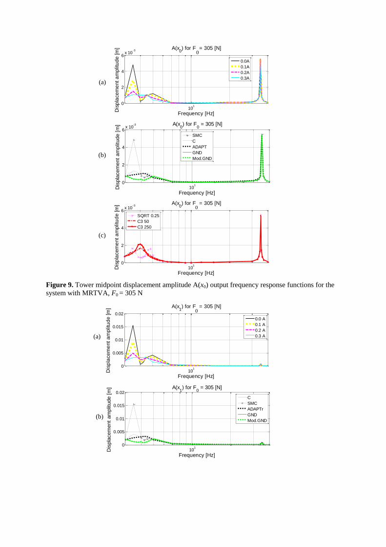
101
0
2
4
6x 10
-3A(x
0) for F
x = 305 [N]
Frequency [Hz]D
isp
lacem
ent a
mplit
ud
e [m
]
00A
01A
02A
03A
10
10
2
4
6x 10
-3 A(x0) for F
0 = 305 [N]
Frequency [Hz]
Dis
pla
cem
ent
am
plit
ude [
m]
SMC
C
ADAPT
GND
ModGND
101
0
2
4
6x 10
-3A(x
0) for F
x = 305 [N]
Frequency [Hz]
Dis
pla
cem
ent a
mplit
ud
e [m
]
SQRT 025
C3 50
C3 250
Figure 9 Tower midpoint displacement amplitude A(x0) output frequency response functions for the
system with MRTVA F0 = 305 N
101
0
0005
001
0015
002
A(x1) for F
x = 305 [N]
Frequency [Hz]
Dis
pla
cem
ent a
mplit
ud
e [m
]
00 A
01 A
02 A
03 A
10
10
0005
001
0015
002A(x
1) for F
0 = 305 [N]
Frequency [Hz]
Dis
pla
cem
ent
am
plit
ude [
m]
C
SMC
ADAPTr
GND
ModGND
0
0
0
(a)
(c)
(b)
(b)
(c)
(a)
101
0
2
4
6
8x 10
-3A(x
1) for Fx = 305 [N]
Frequency [Hz]D
isp
lacem
ent a
mplit
ud
e [m
]
SQRT 025
C3 50
C3 250
Figure 10 Tower tip displacement amplitude A(x1) output frequency response functions for the
system with MRTVA F0 = 305 N
The presented results prove the potential of MRTVA in tower-nacelle system vibration reduction at
frequency of the 1st bending mode without deterioration at other frequencies Substitution of passive
TVA with MRTVA enables further vibration reduction by application of dedicated control solutions
Maximum amplitudes obtained with GND and ModGDN control algorithms were in the majority of
simulation scenarios lesser than half of the maximum amplitudes of the system emulating linear
damping as in standard TVA with passive viscous damper (designated by C) The accuracy of passive
damper force follow-up is limited by the actuator nature The advantage of ModGDN algorithm over
GND may be observed eg at frequency of 50 Hz (Figure 7 and Figure 8) MR damper current control
operation is demonstrated by PMR force values switches reflecting control current impulses between
0 and max
MRi Time plots presented in Figures 11 and 12 prove that equation (5) produces more favourable
MR damper control pattern (observed as x1 amplitude reduction) than equation (4) due to hysteresis
phenomenon of MR damper force-velocity characteristics ModGDN algorithm implemented on the
experimental ground in comparison with GND algorithm is presented as a separate publication
(Martynowicz 2015)
1975 198 1985 199 1995
-6
-4
-2
0
2
4
6
Time [s]
Dis
pla
ce
me
nt C
urr
en
t F
orc
e
F0=305 N
x110
4 [m]
(x1-x
2)10
3 [m]
iMR
[A]
PMR
10-1
[N]
Figure 11 Tower tip displacement x1 MR damper travel x1ndashx2 current iMR and force PMR for the
feedback system with GND algorithm F0 = 305 N
1975 198 1985 199 1995
-6
-4
-2
0
2
4
6
Time [s]
Dis
pla
ce
me
nt C
urr
en
t F
orc
e
F0=305 N
x110
4 [m]
(x1-x
2)10
3 [m]
iMR
[A]
PMR
10-1
[N]
Figure 12 Tower tip displacement x1 MR damper travel x1ndashx2 current iMR and force PMR for the
feedback system with ModGND algorithm F0 = 305 N
As depicted above effectiveness of the adaptive control was limited by MR damper semi-active type
of actuation and its force variation range precluding MRTVA possibility to adapt to 2nd
bending mode
(even neglecting MR damper response time) while benefits of ADAPT over standard TVA (ie linear
0
(c)
damping C) are noticeable The ADAPT results are quite on par with most favourable open-loop
system (01 A) results for P0 (tower tip) excitation (Figures 7ndash8) However for F0 (tower midpoint)
excitation of the 1st mode (Figures 9ndash10) ADAPT copes better than 01 A open-loop system and
comparable to 03 A open-loop (which in turn delivers less favourable characteristics than ADAPT for
P0 excitation) Consequently ADAPT algorithm presents better performance than 02 A and 00 A
open-loop systems in all conditions considered Further analyses of ADAPT for system parameters
uncertainty may be planned in the future The sliding mode and nonlinear damping control solutions
deliver no apparent advantage over MRTVA emulating viscous damping C Further analyses are
considered It was also determined that for laboratory model 2nd
bending mode amplitude A(x1) is
relatively small (A(x1) ltlt A(x0)) (see Figure 2 (c) Figures 6 ndash 10) as mass of the nacelle is much
higher than tower mass Moreover regarding MR damper response time and value of 2nd
bending
mode frequency vibration reduction possibilities of MRTVA is very much limited to the 1st bending
mode However in real-world applications nacelle displacement amplitude is meaningful for 2nd
bending mode while its frequency is below 5 Hz thus vibration reduction possibilities of MRTVA
located at the nacelle are there
It is worth to point out that ComsolSimulink co-simulation analyses give the possibilities of testing
various MR damper control algorithms for the continuous-discrete system modelled in FEM
environment however computational load is very significant and time consuming
Validation analyses
The results obtained in the previous section serve as a basis for validation analyses of the regarded
model vs full-scale Vensys 82 wind turbine tower-nacelle baseline structure assuming nacelle and
turbine to be a one solid body (excluding blades aerodynamics) It was previously proven (Snamina and
Martynowicz 2014 Snamina et al 2014) that conditions of partial dynamic similarity (similarity of
motion of tower tips) between regarded model and full-scale structure are fulfilled Now these former
results are verified using FEM model of Vensys 82 tower-nacelle structure embedded (similarly as
presented above) in Simulink environment with MRTVA model and dedicated control algorithm For
these analyses ModGND algorithm was chosen and compared with reference structure without
MRTVA Vensys 82 tower-nacelle structure FEM model was built as 9-segment non-prismatic beam (a
tower) with a solid body mass and mass moments of inertia as a nacelleturbine Additionally modified
configuration is proposed with tower massstiffness reduced by the factor of two thanks to the load
mitigation by utilisation of MRTVA along with proper vibration control algorithm The proposed
modified tower structure is of the same height and external diameter vertical profile as original
structure however wall thickness is ca half of the original one Table 1 presents assumed parameters of
the full-scale structure vs its scaled model and proposed modified structure as well as maximum
bending stress maximum deflection and maximum acceleration values corresponding to 1st bending
mode of vibration neighbourhood Comparison of the configuration with and without MRTVA is
presented for sine horizontal excitation applied to the nacelle (P) for each structure model (for modified
Vensys 82 model variant without MRTVA cannot be considered due to large bending stress values)
For both original and modified Vensys 82 models with MRTVA MR damper force is assumed
according to the conclusion of dynamic similarity analysis (see Snamina and Martynowicz 2014)
Regarding real-world turbine aerodynamic damping preferable TVA operation direction should lie
within the plane parallel to the rotor plane Figures 13 and 14 present tower tip (nacelle) displacement
and acceleration amplitude output frequency response functions for baseline and modified Vensys 82
models with MRTVA and ModGND algorithm assuming P0 = 25103 N
As can be observed in Figures 14 implementation of 65103 kg absorber with appropriate spring and
MR damper selection along with real-time measurement and control system may lead to both structure
overall mass decrease by 78103 kg (or more up to 84510
3 kg assuming that some nacelle
equipmentframe mass may operate in motion ndash as absorber mass) and significant bending loads
deflections and accelerations decrease in comparison with baseline Vensys 82 structure without
MRTVA In case of measurement control MR damper failure internal system watchdog should
execute a switch to a passive regime with zero MR damper current that still provides satisfactory
properties ndash in fact some further MR damper force amplitude ModGND control system tuning
possibilities (leading to further deflections decrease for ModGND system) may be inferred from
ModGND and 00 A curves observation To eliminate (marginally small) risk of MR damper TVA
lock-up failure it may be considered the implementation of both multi-MR-damper TVA system (MR
damper redundancy) and additional passive TVA system with significantly lower absorber mass m2
that is normally-locked (TVA redundancy) ultimate solution would be particular turbine switch off
cut-out within ca 500 seconds (depending on tower steel properties) of resonant vibration when
bending stress value for modified Vensys 82 structure is expected to be similar as maximum bending
stress for baseline Vensys 82 with no TVA according to ComsolSimulink analysis with P0 = 25103 N
Table 1 Assumed models parameters and numerical results validation (1st bending mode neighbourhood)
Model TVA
Parameter
Scaled simulation
model
Baseline Vensys 82
model
Modified Vensys 82
model
no TVA MRTVA no TVA MRTVA no TVA MRTVA
Tower type Prismatic rod Non-prismatic tube Non-prismatic tube
Tower mass [kg] 256 1690103 84510
3
Tower external diameter [m] 007 452 to 330 452 to 330
Tower height [m] 15 850 850
Mass of the assembly located at the
top (nacelle wo absorber) [kg]
1662 1506 904103 77410
3 90410
3 83910
3
Absorber mass [kg] ndash 156 ndash 130103 ndash 6510
3
Mass ratio μ [] ndash 100 ndash 126 ndash 67
TVA spring stiffness [Nm] ndash 952103 ndash 559710
3 ndash 163310
3
Amplitude of horizontal load (P0) [N] 305 25103 2510
3
Results
Maximum displacement [m]
(top end of the tower nacelle)
0079 05510ndash3
306 0048 798 0134
Maximum acceleration [ms2]
(top end of the tower nacelle)
509 0490 150 0263 228 0331
Maximum bending stress [Pa]
(bottom end of the tower)
406106 28210
6 39710
6 68810
6 113010
6 19010
6
10-06
10-05
10-04
10-03
001
002
003
004
005
A(x1) for P
0 = 25
10
3 [N]
Frequency [Hz]
Dis
pla
cem
ent
am
plit
ude [
m]
ModGND
10
-0610
-0510
-0410
-030
01
02
03
Frequency [Hz]Accele
ration a
mplit
ude [
ms
2]
A(x1) for P
0 = 25
10
3 [N]
ModGND
Figure 13 Tower tip displacement amplitude (left) and acceleration amplitude (right) output
frequency response functions for baseline Vensys 82 model with MRTVA (see Table 1)
10-07
10-06
10-05
10-04
0
005
01
015
02
A(x1) for P
0 = 25
10
3 [N]
Frequency [Hz]
Dis
pla
cem
ent
am
plit
ude [
m]
00 A
ModGND
10-07
10-06
10-05
10-04
0
01
02
03
04
05
A(x1) for P
0 = 25
10
3 [N]
Frequency [Hz]Accele
ration a
mplit
ude [
ms
2]
00 A
ModGND
Figure 14 Tower tip displacement amplitude (left) and acceleration amplitude (right) output
frequency response functions for modified Vensys 82 model with MRTVA (see Table 1)
Laboratory test rig
Laboratory test rig of wind turbine tower-nacelle system (Figure 15) was build according to the details specified in the Wind turbine tower-nacelle model section It consists of vertically oriented titanium (Ti Gr5) rod 1 (representing wind-turbine tower) and a set of steel plates 2 (representing nacelle and turbine assemblies) fixed to the top of the rod 1 with MRTVA embedded Titanium rod is rigidly mounted to the steel foundation frame 3 MRTVA 4 is an additional mass moving horizontally along linear bearing guides connected with the assembly representing nacelle via spring and Lord RD 1097-1 MR damper (Lord Rheonetic 2002) in parallel RD 1097-1 damper (which force depends on the current fed to its coil) is an actuator of such a vibration reduction system MRTVA operates along the same direction as vibration excitation applied to the system Force generated by vibration excitation system ie The Modal Shop lightweight electrodynamic force exciter of 2060E series (TMS 2060E) (TMS 2010) 5 with drive train assembly 6 of changeable leverage (enabling changeable force displacement and velocity ranges) may be applied either to the rod 1 (modelling the tower as in the picture) or to the set of steel plates 2 modelling nacelleturbine Excitation signal is generated by LDS Dactron 7 and amplified by TMS 2100E21-400 8
Measurement and control system consists of laser vibrometer (x1) with its controller 9 laser
displacement transducer (x0) 10 LVDT transducer (x1ndash x2) 11 tensometric stress transducers 12 force
(PMR among others) and acceleration transducers (not apparent in the picture) as well as transducers
supplyconditioning system including MR damper signal amplifier 13 and measuring-control PC 14
with MATLABSimulinkRT-CON applications (measured signals designations listed in brackets)
Selected test rig identification results are presented in the Table 2 while full identification problem is
covered by authorrsquos separate publication
Table 2 Selected parameters of laboratory test rig
Length of the rod [10ndash3
m] 1507
Diameter of the rod [10ndash3
m] 705
Mass of the rod [kg] 2606
Mass of the assembly located at the top (nacelle with TVA) [kg] 15535
Figure 15 Laboratory test rig
1
2
4
3
5
6
7
8
9 13
14 10 12
12
11
Laboratory test rig gives the possibility to model wind turbine tower vibration under various excitation sources Moreover the rig may be laid down on the horizontally excited platform to model vibration of buoy-floating wind turbine structures or vibration due to seismic excitation The above mentioned problems are described in detail in separate publications (Martynowicz 2014a Martynowicz and Szydło 2014 Snamina et al 2014)
Laboratory tests
Preliminary laboratory tests results are presented here Initial analyses were conducted with relatively
low excitation amplitudes to assure test facility safe operation The first was excitation test with sine
force of changing frequency (chirp) The force had horizontal direction constant amplitude of 346 N
and was applied to the rod (tower) midpoint (thus F0 = 346 N) Figures 16 (a)(b) present time section
of x0 and x1 displacement response within ca (360 430) Hz range for feedback system with modified
ground-hook (ModGND) control algorithm in comparison with open-loop system (with 00A MR
damper input current) exhibiting lowest x0 and x1 displacement amplitudes The range of (360 430)
Hz comprises 1st tower bending mode of vibration occurring for the system with MRTVA lsquolockedrsquo
(by input current of 06 A) at frequency of 382 Hz that is ca 02 Hz lower than frequency predicted
by Comsol Multiphysics analyses Such a relation between frequencies was predictable as FEM
method imposes the additional stiffness on the model while mass of test rig nacelle with MRTVA is
slightly higher than nacelle mass assumed for FEM model (see Tables 2 and 3) Some differences in
tower theoretical and laboratory model parameters are present too The maximum displacements
amplitudes max(A(x1)) max(A(x0)) and their ratio max(A(x1))max(A(x0)) as well as maximum MR
damper force values for MRTVA system operating in open-loop and feedback modes are all collected
in the Table 3
It is worth to note that MRTVA operating in feedback mode is by a small margin the most effective in
tower deflection x0 and x1 reduction (Table 3 Figures 16) and simultaneously (thanks to displacements
amplitudes minimisation) generates lowest value of maximum MR damper force Maximum
displacements amplitudes ratio values (resulting from the vibration mode shape) variation is
insignificant for selected MR damper input current values however it displays some system
nonlinearities
0 20 40 60-5
0
5x 10
-4
Time [s]
Tow
er
mid
poin
t dis
pla
cem
ent x 0
[m
]
00 A
ModGND
0 20 40 60-2
-1
0
1
2x 10
-3
Time [s]
Tow
er
tip d
ispla
cem
ent x 1
[m
]
00 A
ModGND
Figure 16 Responses of tower-nacelle system under chirp-type excitation
(a)
(b)
Table 3 Results of chirp-type excitation laboratory tests
Configuration Details Open-loop mode Feedback mode
ModGND (Figures 16) 000 A 005 A 010 A 020 A
Max displ ampl
max(A(w0)) [10ndash3
m]
045 047 059 083 039
Max displ ampl
max(A(w1)) [10ndash3
m]
154 167 199 289 138
max(A(w1)) max(A(w0)) 346 353 340 350 351
Max MR Damper Force [N] 300 319 478 887 278
On a ground of these results frequency characteristics were evaluated Figures 17 (a)(b) present A(x0)
and A(x1) output frequency response functions determined at F0 = 305 N excitation within
(3 40) Hz frequency range for the open-loop system with 00 A and 01 A input currents 06 A input
current (ie MRTVA in lsquolockedrsquo state) and feedback system with ModGND algorithm These
characteristics as well as x0 and x1 displacement amplitude values from the Table 3 indicate system is
more damped than simulation model (details in authorrsquos separate paper on test rig identification) The
typical for TVA two maxima cannot be observed in Figures 17 for 00 A as for simulation model All
of that causes control results to be compromised as lowest control signal value of 00 A is
simultaneously the input current providing the best vibration reduction results from among all open-
loop solutions with constant input current (Table 3 Figures 17) in relatively low force excitation
conditions
Following the above results and conclusions the next test was undergone with significantly higher
excitation amplitude within the most interesting 1st bending resonance neighbourhood range Figures
18 (a)(b) present A(x0) and A(x1) output frequency response functions determined at F0 = 150 N
(325 500) Hz excitation conditions for the open-loop system with 00 A input current and feedback
system with ModGND algorithm As can be inferred from Figures 18 (in comparison with Figures
17) MR damper pre-yield force is less dominant at relatively high excitation amplitudes thus some
control possibilities are there in comparison with 00 A open-loop system for which also the two local
maxima are apparent as for the system with standard passive TVA
10
1
2
4
6
8
10
12
x 10-4
Frequency [Hz]
Dis
pla
cem
ent
am
plit
ude [
m]
A(x0) for F
0 = 305 N
00 A
01 A
06 A
ModGND
10
10
05
1
15
2
25x 10
-3
Frequency [Hz]
Dis
pla
cem
ent
am
plit
ude [
m]
A(x1) for F
0 = 305 N
00 A
01 A
06 A
ModGND
Figure 17 Tower midpoint displacement amplitude A(x0) and tower tip displacement amplitude A(x1)
output frequency response functions
(a)
(b)
10
05210
05510
05810
06110
06410
0670
2
4
6
8x 10
-4
Frequency [Hz]
Dis
pla
cem
ent
am
plit
ude [
m] A(x
0) for F
0 = 150 N
00 A
ModGND
10
05210
05510
05810
06110
06410
06705
1
15
2
25x 10
-3
Frequency [Hz]
Dis
pla
cem
ent
am
plit
ude [
m] A(x
1) for F
0 = 150 N
00 A
ModGND
Figure 18 Tower midpoint displacement amplitude A(x0) and tower tip displacement amplitude A(x1)
output frequency response functions
To more completely cope with the problem of too much MRTVA damping test rig was reconfigured
by increasing nacelle and absorber masses as well as stiffness of TVA spring thus increasing damping
ratio (and so MR damper input current) required for optimum (Den Hartog 1985) TVA operation
while maintaining x1 and x2 displacements ranges (the laboratory test rig was designed in such a way
that masses of the nacelle absorber as well as spring stiffness may be changed while MR damper
type change is not considered due to limited market availability) The preliminary results obtained for
the reconfigured system are presented in Figures 19 (a)(b) As can be observed ModGND system
delivers the most favourable response over the regarded (272 472) Hz frequency range as compared
with the passive system with 00 A and 01 A control currents
1005
1006
0
05
1
15x 10
-3
Frequency [Hz]
Dis
pla
cem
ent
am
plit
ude [
m]
A(x0) for F
0 = 150 N
00 A
01 A
ModGND
1005
1006
0
1
2
3
4
5x 10
-3
Frequency [Hz]
Dis
pla
cem
ent
am
plit
ude [
m]
A(x1) for F
0 = 150 N
00 A
01 A
ModGND
Figure 19 Tower midpoint displacement amplitude A(x0) and tower tip displacement amplitude A(x1)
output frequency response functions (after reconfiguration)
(a)
(b)
(a)
(b)
Conclusion
The conducted comprehensive simulation study delivers a lot of valuable data concerning vibration reduction of tower-nacelle model with MRTVA Vibration control results for the system equipped with MRTVA are improved in relation with the system that emulates standard TVA with linear (viscous) damper ComsolSimulink co-simulation tool is a good solution for control algorithms analysis prototyping and implementation for continuous and continuous-discrete systems however computational time is quite a problem
The results of simulation analyses along with calculations concerning dynamic similarity of the proposed model with Vensys 82 real-world wind turbine (Snamina and Martynowicz 2014 Snamina et al 2014) served for estimation of the benefits of implementation of MRTVA for a full-scale structure These include possible reduction of structure overall mass significant reduction of tower deflection (thus bending fatigue) and nacelle acceleration amplitudes as well as possible operation at higher RPM to increase power production and decrease cost of energy factor while reducing risk of structure failure due to wind waves or earthquake induced vibration The cost analysis however is nor subject of current research project
Previous section results proved the laboratory test rig was more damped than simulation model and that compromised control possibilities as minimum control signal for feedback system (00 A) was providing the best vibration reduction results in open-loop case for low excitation amplitudes (F0 = 305 N and F0 = 346 N) To cope with that problem excitation amplitude was increased (F0 = 150 N) and test rig was reconfigured Some preliminary laboratory-based validation results of new laboratory validation tests are presented here while their full scope is covered by the separate papers (Martynowicz 2015 Rosoacuteł and Martynowicz 2015)
Further work program includes wide cooperation on implementation of such designed MRTVA system in the full scale structure within the scope of EU project
Acknowledgment
This work was financed by the Polish National Science Centre project no 2286BT02201140
References
Bak C Bitsche R Yde A Kim T Hansen MH Zahle F Gaunaa M Blasques J Dossing M Wedel-
Heinen JJ and Behrens T (2012) Light Rotor The 10-MW reference wind turbine In European Wind
Energy Association Annual Event 16ndash19042012 Copenhagen Denmark
Butt UA and Ishihara T (2012) Seismic Load Evaluation of Wind Turbine Support Structures
Considering Low Structural Damping and Soil Structure Interaction In European Wind Energy
Association Annual Event 16ndash19042012 Copenhagen Denmark
Den Hartog JP (1985) Mechanical Vibrations Mineola Dover Publications
Enevoldsen I and Mork KJ (1996) Effects of Vibration Mass Damper in a Wind Turbine Tower Mech
Struct amp Mach 24(2) 155ndash187
Hansen MH Fuglsang P Thomsen K and Knudsen T (2012) Two Methods for Estimating Aeroelastic
Damping of Operational Wind Turbine Modes from Experiments In European Wind Energy
Association Annual Event 16ndash19042012 Copenhagen Denmark
Jain P (2011) Wind Energy Engineering McGRAW-HILL
Jelavić M Perić N and Petrović I (2007) Damping of Wind Turbine Tower Oscillations through Rotor
Speed Control In International Conference on Ecologic Vehicles amp Renewable Energies March 29ndash
April 1 2007 Monaco
Kciuk S and Martynowicz P (2011) Special application magnetorheological valve numerical and
experimental analysis Control engineering in materials processing Diffusion and Defect Data ndash Solid
State Data Pt B Solid State Phenomena Vol 177 102ndash115
Kirkegaard PH Nielsen SRK Poulsen BL Andersen J Pedersen LH and Pedersen BJ (2002)
Semiactive vibration control of a wind turbine tower using an MR damper In Grundmann H and
Schueller GI (eds) Struct Dynamics EURODYN Lisse Swets amp Zeitlinger
Koo JH and Ahmadian M (2007) Qualitative Analysis of Magneto-Rheological Tuned Vibration
Absorbers Experimental Approach Journal of Intelligent Material Systems and Structures Vol 18
December 2007
Laalej H Lang ZQ Sapinski B and Martynowicz P (2012) MR damper based implementation of
nonlinear damping for a pitch plane suspension system Smart Materials and Structures Vol 21
Lord Rheonetic (2002) MR Controllable Friction Damper RD-1097-01 Product Bulletin
Łatas W and Martynowicz P (2012) Modelowanie drgań układu maszt-gondola elektrowni wiatrowej
z tłumikiem dynamicznym Modelowanie Inżynierskie nr 44 t 13 187ndash198
Martynowicz P (2014a) Development of Laboratory Model of Wind Turbines Tower-Nacelle System
with Magnetorheological Tuned Vibration Absorber Solid State Phenomena Vol 208 40ndash51
Martynowicz P (2014b) Wind turbines tower-nacelle model with magnetorheological tuned vibration
absorber ndash numerical and experimental analysis In 6WCSCM Sixth World Conference on Structural
Control and Monitoring ndash proceedings of the 6th edition of the World conference of the International
Association for Structural Control and Monitoring (IACSM) Barcelona Spain 15ndash17 July 2014
Martynowicz P (2015) Study of vibration control using laboratory test rig of wind turbinersquos tower-
nacelle system with MR damper based tuned vibration absorber Bulletin of the Polish Academy of
Sciences Technical Sciences (in review)
Martynowicz P and Szydło Z (2013) Wind turbines tower-nacelle model with magnetorheological
tuned vibration absorber the laboratory test rig In Proceedings of the 14th International Carpathian
Control Conference (ICCC) Rytro Poland May 26ndash29 2013
Maślanka M Sapiński B and Snamina J (2007) Experimental Study of Vibration Control of a Cable
With an Attached MR Damper Journal of Theoretical and Applied Mechanics 45 4 893ndash917
Warsaw
Matachowski F and Martynowicz P (2012) Analiza dynamiki konstrukcji elektrowni wiatrowej z
wykorzystaniem środowiska Comsol Multiphysics Modelowanie Inżynierskie nr 44 t 13 209ndash216
Namik H and Stol K (2011) Performance analysis of individual blade pitch control of offshore wind
turbines on two floating platforms Mechatronics 21 691ndash703
Neelakantan VA and Washington GN (2008) Vibration Control of Structural Systems using MR
dampers and a lsquoModifiedrsquo Sliding Mode Control Technique Journal of Intelligent Material Systems
and Structures Vol 19
Oh S and Ishihara T (2013) A Study on Structure Parameters of an Offshore Wind Turbine by
Excitation test Using Active Mass Damper In EWEA Offshore 19-21112013 Frankfurt
Rosoacuteł M and Martynowicz P (2015) Identification of Laboratory Model of Wind Turbinersquos Tower-
Nacelle System with MR Damper Based Tuned Vibration Absorber Mechanical Systems and Signal
Processing (in review)
Rotea MA Lackner MA and Saheba R (2010) Active Structural Control of Offshore Wind turbines
In 48th AIAA Aerospace Sciences Meeting Including the New Horizons Forum and Aerospace
Exposition 4ndash7 January 2010 Orlando Florida
Sapiński B (2008) Real-time control of magnetorheological dampers in mechanical systems Cracow
AGH University of Science and Technology Press
Sapiński B and Rosoacuteł M (2008) Autonomous control system for a 3 DOF pitch-plane suspension
system with MR shock absorbers Computers and Structures 86 379ndash385
Sapiński B (2011) Experimental study of a self-powered and sensing MR damper-based vibration
control system Smart Materials and Structures 20 105007
Shan W and Shan M (2012) Gain Scheduling Pitch Control Design for Active Tower Damping and 3p
Harmonic Reduction In European Wind Energy Association Annual Event 16ndash19042012
Copenhagen Denmark
Shen YJ Wang L Yang SP and Gao GS (2013) Nonlinear dynamical analysis and parameters
optimization of four semi-active on-off dynamic vibration absorbers Journal of Vibration and
Control January 2013 vol 19 no 1 143ndash160
Snamina J Martynowicz P and Łatas W (2014) Dynamic similarity of wind turbinersquos tower-nacelle
system and its scaled model Solid State Phenomena Vol 208 29ndash39
Snamina J and Martynowicz P (2014) Prediction of characteristics of wind turbines tower-nacelle
system from investigation of its scaled model In 6WCSCM Sixth World Conference on Structural
Control and Monitoring ndash proceedings of the 6th edition of the World conference of the International
Association for Structural Control and Monitoring (IACSM) Barcelona Spain 15ndash17 July 2014
TMS (2010) 60 Lbf Modal Shaker The Modal Shop Inc
Tsouroukdissian A Carcangiu CE Pineda Amo I Martin M Fischer T Kuhnle B and Scheu M
(2011) Wind Turbine Tower Load Reduction using Passive and Semiactive Dampers European Wind
Energy Association Annual Event Brussels
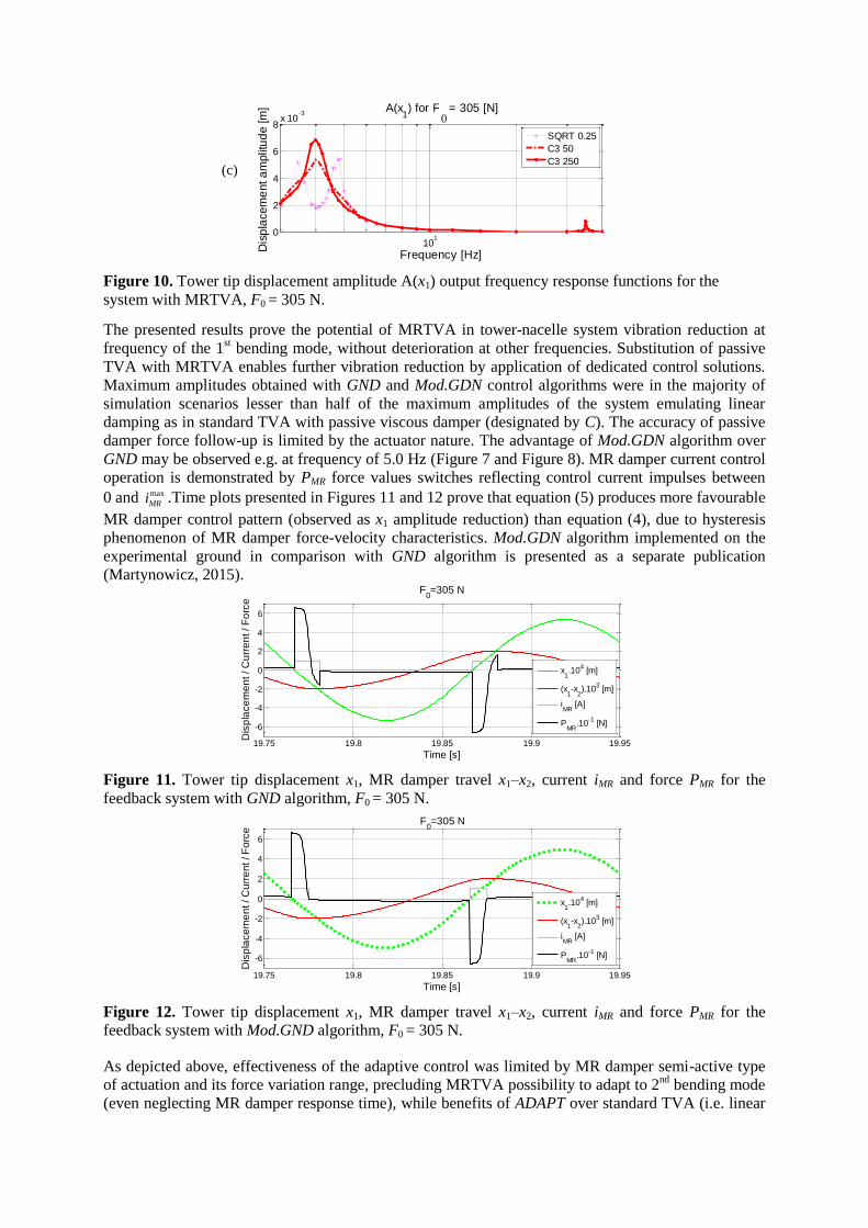
101
0
2
4
6
8x 10
-3A(x
1) for Fx = 305 [N]
Frequency [Hz]D
isp
lacem
ent a
mplit
ud
e [m
]
SQRT 025
C3 50
C3 250
Figure 10 Tower tip displacement amplitude A(x1) output frequency response functions for the
system with MRTVA F0 = 305 N
The presented results prove the potential of MRTVA in tower-nacelle system vibration reduction at
frequency of the 1st bending mode without deterioration at other frequencies Substitution of passive
TVA with MRTVA enables further vibration reduction by application of dedicated control solutions
Maximum amplitudes obtained with GND and ModGDN control algorithms were in the majority of
simulation scenarios lesser than half of the maximum amplitudes of the system emulating linear
damping as in standard TVA with passive viscous damper (designated by C) The accuracy of passive
damper force follow-up is limited by the actuator nature The advantage of ModGDN algorithm over
GND may be observed eg at frequency of 50 Hz (Figure 7 and Figure 8) MR damper current control
operation is demonstrated by PMR force values switches reflecting control current impulses between
0 and max
MRi Time plots presented in Figures 11 and 12 prove that equation (5) produces more favourable
MR damper control pattern (observed as x1 amplitude reduction) than equation (4) due to hysteresis
phenomenon of MR damper force-velocity characteristics ModGDN algorithm implemented on the
experimental ground in comparison with GND algorithm is presented as a separate publication
(Martynowicz 2015)
1975 198 1985 199 1995
-6
-4
-2
0
2
4
6
Time [s]
Dis
pla
ce
me
nt C
urr
en
t F
orc
e
F0=305 N
x110
4 [m]
(x1-x
2)10
3 [m]
iMR
[A]
PMR
10-1
[N]
Figure 11 Tower tip displacement x1 MR damper travel x1ndashx2 current iMR and force PMR for the
feedback system with GND algorithm F0 = 305 N
1975 198 1985 199 1995
-6
-4
-2
0
2
4
6
Time [s]
Dis
pla
ce
me
nt C
urr
en
t F
orc
e
F0=305 N
x110
4 [m]
(x1-x
2)10
3 [m]
iMR
[A]
PMR
10-1
[N]
Figure 12 Tower tip displacement x1 MR damper travel x1ndashx2 current iMR and force PMR for the
feedback system with ModGND algorithm F0 = 305 N
As depicted above effectiveness of the adaptive control was limited by MR damper semi-active type
of actuation and its force variation range precluding MRTVA possibility to adapt to 2nd
bending mode
(even neglecting MR damper response time) while benefits of ADAPT over standard TVA (ie linear
0
(c)
damping C) are noticeable The ADAPT results are quite on par with most favourable open-loop
system (01 A) results for P0 (tower tip) excitation (Figures 7ndash8) However for F0 (tower midpoint)
excitation of the 1st mode (Figures 9ndash10) ADAPT copes better than 01 A open-loop system and
comparable to 03 A open-loop (which in turn delivers less favourable characteristics than ADAPT for
P0 excitation) Consequently ADAPT algorithm presents better performance than 02 A and 00 A
open-loop systems in all conditions considered Further analyses of ADAPT for system parameters
uncertainty may be planned in the future The sliding mode and nonlinear damping control solutions
deliver no apparent advantage over MRTVA emulating viscous damping C Further analyses are
considered It was also determined that for laboratory model 2nd
bending mode amplitude A(x1) is
relatively small (A(x1) ltlt A(x0)) (see Figure 2 (c) Figures 6 ndash 10) as mass of the nacelle is much
higher than tower mass Moreover regarding MR damper response time and value of 2nd
bending
mode frequency vibration reduction possibilities of MRTVA is very much limited to the 1st bending
mode However in real-world applications nacelle displacement amplitude is meaningful for 2nd
bending mode while its frequency is below 5 Hz thus vibration reduction possibilities of MRTVA
located at the nacelle are there
It is worth to point out that ComsolSimulink co-simulation analyses give the possibilities of testing
various MR damper control algorithms for the continuous-discrete system modelled in FEM
environment however computational load is very significant and time consuming
Validation analyses
The results obtained in the previous section serve as a basis for validation analyses of the regarded
model vs full-scale Vensys 82 wind turbine tower-nacelle baseline structure assuming nacelle and
turbine to be a one solid body (excluding blades aerodynamics) It was previously proven (Snamina and
Martynowicz 2014 Snamina et al 2014) that conditions of partial dynamic similarity (similarity of
motion of tower tips) between regarded model and full-scale structure are fulfilled Now these former
results are verified using FEM model of Vensys 82 tower-nacelle structure embedded (similarly as
presented above) in Simulink environment with MRTVA model and dedicated control algorithm For
these analyses ModGND algorithm was chosen and compared with reference structure without
MRTVA Vensys 82 tower-nacelle structure FEM model was built as 9-segment non-prismatic beam (a
tower) with a solid body mass and mass moments of inertia as a nacelleturbine Additionally modified
configuration is proposed with tower massstiffness reduced by the factor of two thanks to the load
mitigation by utilisation of MRTVA along with proper vibration control algorithm The proposed
modified tower structure is of the same height and external diameter vertical profile as original
structure however wall thickness is ca half of the original one Table 1 presents assumed parameters of
the full-scale structure vs its scaled model and proposed modified structure as well as maximum
bending stress maximum deflection and maximum acceleration values corresponding to 1st bending
mode of vibration neighbourhood Comparison of the configuration with and without MRTVA is
presented for sine horizontal excitation applied to the nacelle (P) for each structure model (for modified
Vensys 82 model variant without MRTVA cannot be considered due to large bending stress values)
For both original and modified Vensys 82 models with MRTVA MR damper force is assumed
according to the conclusion of dynamic similarity analysis (see Snamina and Martynowicz 2014)
Regarding real-world turbine aerodynamic damping preferable TVA operation direction should lie
within the plane parallel to the rotor plane Figures 13 and 14 present tower tip (nacelle) displacement
and acceleration amplitude output frequency response functions for baseline and modified Vensys 82
models with MRTVA and ModGND algorithm assuming P0 = 25103 N
As can be observed in Figures 14 implementation of 65103 kg absorber with appropriate spring and
MR damper selection along with real-time measurement and control system may lead to both structure
overall mass decrease by 78103 kg (or more up to 84510
3 kg assuming that some nacelle
equipmentframe mass may operate in motion ndash as absorber mass) and significant bending loads
deflections and accelerations decrease in comparison with baseline Vensys 82 structure without
MRTVA In case of measurement control MR damper failure internal system watchdog should
execute a switch to a passive regime with zero MR damper current that still provides satisfactory
properties ndash in fact some further MR damper force amplitude ModGND control system tuning
possibilities (leading to further deflections decrease for ModGND system) may be inferred from
ModGND and 00 A curves observation To eliminate (marginally small) risk of MR damper TVA
lock-up failure it may be considered the implementation of both multi-MR-damper TVA system (MR
damper redundancy) and additional passive TVA system with significantly lower absorber mass m2
that is normally-locked (TVA redundancy) ultimate solution would be particular turbine switch off
cut-out within ca 500 seconds (depending on tower steel properties) of resonant vibration when
bending stress value for modified Vensys 82 structure is expected to be similar as maximum bending
stress for baseline Vensys 82 with no TVA according to ComsolSimulink analysis with P0 = 25103 N
Table 1 Assumed models parameters and numerical results validation (1st bending mode neighbourhood)
Model TVA
Parameter
Scaled simulation
model
Baseline Vensys 82
model
Modified Vensys 82
model
no TVA MRTVA no TVA MRTVA no TVA MRTVA
Tower type Prismatic rod Non-prismatic tube Non-prismatic tube
Tower mass [kg] 256 1690103 84510
3
Tower external diameter [m] 007 452 to 330 452 to 330
Tower height [m] 15 850 850
Mass of the assembly located at the
top (nacelle wo absorber) [kg]
1662 1506 904103 77410
3 90410
3 83910
3
Absorber mass [kg] ndash 156 ndash 130103 ndash 6510
3
Mass ratio μ [] ndash 100 ndash 126 ndash 67
TVA spring stiffness [Nm] ndash 952103 ndash 559710
3 ndash 163310
3
Amplitude of horizontal load (P0) [N] 305 25103 2510
3
Results
Maximum displacement [m]
(top end of the tower nacelle)
0079 05510ndash3
306 0048 798 0134
Maximum acceleration [ms2]
(top end of the tower nacelle)
509 0490 150 0263 228 0331
Maximum bending stress [Pa]
(bottom end of the tower)
406106 28210
6 39710
6 68810
6 113010
6 19010
6
10-06
10-05
10-04
10-03
001
002
003
004
005
A(x1) for P
0 = 25
10
3 [N]
Frequency [Hz]
Dis
pla
cem
ent
am
plit
ude [
m]
ModGND
10
-0610
-0510
-0410
-030
01
02
03
Frequency [Hz]Accele
ration a
mplit
ude [
ms
2]
A(x1) for P
0 = 25
10
3 [N]
ModGND
Figure 13 Tower tip displacement amplitude (left) and acceleration amplitude (right) output
frequency response functions for baseline Vensys 82 model with MRTVA (see Table 1)
10-07
10-06
10-05
10-04
0
005
01
015
02
A(x1) for P
0 = 25
10
3 [N]
Frequency [Hz]
Dis
pla
cem
ent
am
plit
ude [
m]
00 A
ModGND
10-07
10-06
10-05
10-04
0
01
02
03
04
05
A(x1) for P
0 = 25
10
3 [N]
Frequency [Hz]Accele
ration a
mplit
ude [
ms
2]
00 A
ModGND
Figure 14 Tower tip displacement amplitude (left) and acceleration amplitude (right) output
frequency response functions for modified Vensys 82 model with MRTVA (see Table 1)
Laboratory test rig
Laboratory test rig of wind turbine tower-nacelle system (Figure 15) was build according to the details specified in the Wind turbine tower-nacelle model section It consists of vertically oriented titanium (Ti Gr5) rod 1 (representing wind-turbine tower) and a set of steel plates 2 (representing nacelle and turbine assemblies) fixed to the top of the rod 1 with MRTVA embedded Titanium rod is rigidly mounted to the steel foundation frame 3 MRTVA 4 is an additional mass moving horizontally along linear bearing guides connected with the assembly representing nacelle via spring and Lord RD 1097-1 MR damper (Lord Rheonetic 2002) in parallel RD 1097-1 damper (which force depends on the current fed to its coil) is an actuator of such a vibration reduction system MRTVA operates along the same direction as vibration excitation applied to the system Force generated by vibration excitation system ie The Modal Shop lightweight electrodynamic force exciter of 2060E series (TMS 2060E) (TMS 2010) 5 with drive train assembly 6 of changeable leverage (enabling changeable force displacement and velocity ranges) may be applied either to the rod 1 (modelling the tower as in the picture) or to the set of steel plates 2 modelling nacelleturbine Excitation signal is generated by LDS Dactron 7 and amplified by TMS 2100E21-400 8
Measurement and control system consists of laser vibrometer (x1) with its controller 9 laser
displacement transducer (x0) 10 LVDT transducer (x1ndash x2) 11 tensometric stress transducers 12 force
(PMR among others) and acceleration transducers (not apparent in the picture) as well as transducers
supplyconditioning system including MR damper signal amplifier 13 and measuring-control PC 14
with MATLABSimulinkRT-CON applications (measured signals designations listed in brackets)
Selected test rig identification results are presented in the Table 2 while full identification problem is
covered by authorrsquos separate publication
Table 2 Selected parameters of laboratory test rig
Length of the rod [10ndash3
m] 1507
Diameter of the rod [10ndash3
m] 705
Mass of the rod [kg] 2606
Mass of the assembly located at the top (nacelle with TVA) [kg] 15535
Figure 15 Laboratory test rig
1
2
4
3
5
6
7
8
9 13
14 10 12
12
11
Laboratory test rig gives the possibility to model wind turbine tower vibration under various excitation sources Moreover the rig may be laid down on the horizontally excited platform to model vibration of buoy-floating wind turbine structures or vibration due to seismic excitation The above mentioned problems are described in detail in separate publications (Martynowicz 2014a Martynowicz and Szydło 2014 Snamina et al 2014)
Laboratory tests
Preliminary laboratory tests results are presented here Initial analyses were conducted with relatively
low excitation amplitudes to assure test facility safe operation The first was excitation test with sine
force of changing frequency (chirp) The force had horizontal direction constant amplitude of 346 N
and was applied to the rod (tower) midpoint (thus F0 = 346 N) Figures 16 (a)(b) present time section
of x0 and x1 displacement response within ca (360 430) Hz range for feedback system with modified
ground-hook (ModGND) control algorithm in comparison with open-loop system (with 00A MR
damper input current) exhibiting lowest x0 and x1 displacement amplitudes The range of (360 430)
Hz comprises 1st tower bending mode of vibration occurring for the system with MRTVA lsquolockedrsquo
(by input current of 06 A) at frequency of 382 Hz that is ca 02 Hz lower than frequency predicted
by Comsol Multiphysics analyses Such a relation between frequencies was predictable as FEM
method imposes the additional stiffness on the model while mass of test rig nacelle with MRTVA is
slightly higher than nacelle mass assumed for FEM model (see Tables 2 and 3) Some differences in
tower theoretical and laboratory model parameters are present too The maximum displacements
amplitudes max(A(x1)) max(A(x0)) and their ratio max(A(x1))max(A(x0)) as well as maximum MR
damper force values for MRTVA system operating in open-loop and feedback modes are all collected
in the Table 3
It is worth to note that MRTVA operating in feedback mode is by a small margin the most effective in
tower deflection x0 and x1 reduction (Table 3 Figures 16) and simultaneously (thanks to displacements
amplitudes minimisation) generates lowest value of maximum MR damper force Maximum
displacements amplitudes ratio values (resulting from the vibration mode shape) variation is
insignificant for selected MR damper input current values however it displays some system
nonlinearities
0 20 40 60-5
0
5x 10
-4
Time [s]
Tow
er
mid
poin
t dis
pla
cem
ent x 0
[m
]
00 A
ModGND
0 20 40 60-2
-1
0
1
2x 10
-3
Time [s]
Tow
er
tip d
ispla
cem
ent x 1
[m
]
00 A
ModGND
Figure 16 Responses of tower-nacelle system under chirp-type excitation
(a)
(b)
Table 3 Results of chirp-type excitation laboratory tests
Configuration Details Open-loop mode Feedback mode
ModGND (Figures 16) 000 A 005 A 010 A 020 A
Max displ ampl
max(A(w0)) [10ndash3
m]
045 047 059 083 039
Max displ ampl
max(A(w1)) [10ndash3
m]
154 167 199 289 138
max(A(w1)) max(A(w0)) 346 353 340 350 351
Max MR Damper Force [N] 300 319 478 887 278
On a ground of these results frequency characteristics were evaluated Figures 17 (a)(b) present A(x0)
and A(x1) output frequency response functions determined at F0 = 305 N excitation within
(3 40) Hz frequency range for the open-loop system with 00 A and 01 A input currents 06 A input
current (ie MRTVA in lsquolockedrsquo state) and feedback system with ModGND algorithm These
characteristics as well as x0 and x1 displacement amplitude values from the Table 3 indicate system is
more damped than simulation model (details in authorrsquos separate paper on test rig identification) The
typical for TVA two maxima cannot be observed in Figures 17 for 00 A as for simulation model All
of that causes control results to be compromised as lowest control signal value of 00 A is
simultaneously the input current providing the best vibration reduction results from among all open-
loop solutions with constant input current (Table 3 Figures 17) in relatively low force excitation
conditions
Following the above results and conclusions the next test was undergone with significantly higher
excitation amplitude within the most interesting 1st bending resonance neighbourhood range Figures
18 (a)(b) present A(x0) and A(x1) output frequency response functions determined at F0 = 150 N
(325 500) Hz excitation conditions for the open-loop system with 00 A input current and feedback
system with ModGND algorithm As can be inferred from Figures 18 (in comparison with Figures
17) MR damper pre-yield force is less dominant at relatively high excitation amplitudes thus some
control possibilities are there in comparison with 00 A open-loop system for which also the two local
maxima are apparent as for the system with standard passive TVA
10
1
2
4
6
8
10
12
x 10-4
Frequency [Hz]
Dis
pla
cem
ent
am
plit
ude [
m]
A(x0) for F
0 = 305 N
00 A
01 A
06 A
ModGND
10
10
05
1
15
2
25x 10
-3
Frequency [Hz]
Dis
pla
cem
ent
am
plit
ude [
m]
A(x1) for F
0 = 305 N
00 A
01 A
06 A
ModGND
Figure 17 Tower midpoint displacement amplitude A(x0) and tower tip displacement amplitude A(x1)
output frequency response functions
(a)
(b)
10
05210
05510
05810
06110
06410
0670
2
4
6
8x 10
-4
Frequency [Hz]
Dis
pla
cem
ent
am
plit
ude [
m] A(x
0) for F
0 = 150 N
00 A
ModGND
10
05210
05510
05810
06110
06410
06705
1
15
2
25x 10
-3
Frequency [Hz]
Dis
pla
cem
ent
am
plit
ude [
m] A(x
1) for F
0 = 150 N
00 A
ModGND
Figure 18 Tower midpoint displacement amplitude A(x0) and tower tip displacement amplitude A(x1)
output frequency response functions
To more completely cope with the problem of too much MRTVA damping test rig was reconfigured
by increasing nacelle and absorber masses as well as stiffness of TVA spring thus increasing damping
ratio (and so MR damper input current) required for optimum (Den Hartog 1985) TVA operation
while maintaining x1 and x2 displacements ranges (the laboratory test rig was designed in such a way
that masses of the nacelle absorber as well as spring stiffness may be changed while MR damper
type change is not considered due to limited market availability) The preliminary results obtained for
the reconfigured system are presented in Figures 19 (a)(b) As can be observed ModGND system
delivers the most favourable response over the regarded (272 472) Hz frequency range as compared
with the passive system with 00 A and 01 A control currents
1005
1006
0
05
1
15x 10
-3
Frequency [Hz]
Dis
pla
cem
ent
am
plit
ude [
m]
A(x0) for F
0 = 150 N
00 A
01 A
ModGND
1005
1006
0
1
2
3
4
5x 10
-3
Frequency [Hz]
Dis
pla
cem
ent
am
plit
ude [
m]
A(x1) for F
0 = 150 N
00 A
01 A
ModGND
Figure 19 Tower midpoint displacement amplitude A(x0) and tower tip displacement amplitude A(x1)
output frequency response functions (after reconfiguration)
(a)
(b)
(a)
(b)
Conclusion
The conducted comprehensive simulation study delivers a lot of valuable data concerning vibration reduction of tower-nacelle model with MRTVA Vibration control results for the system equipped with MRTVA are improved in relation with the system that emulates standard TVA with linear (viscous) damper ComsolSimulink co-simulation tool is a good solution for control algorithms analysis prototyping and implementation for continuous and continuous-discrete systems however computational time is quite a problem
The results of simulation analyses along with calculations concerning dynamic similarity of the proposed model with Vensys 82 real-world wind turbine (Snamina and Martynowicz 2014 Snamina et al 2014) served for estimation of the benefits of implementation of MRTVA for a full-scale structure These include possible reduction of structure overall mass significant reduction of tower deflection (thus bending fatigue) and nacelle acceleration amplitudes as well as possible operation at higher RPM to increase power production and decrease cost of energy factor while reducing risk of structure failure due to wind waves or earthquake induced vibration The cost analysis however is nor subject of current research project
Previous section results proved the laboratory test rig was more damped than simulation model and that compromised control possibilities as minimum control signal for feedback system (00 A) was providing the best vibration reduction results in open-loop case for low excitation amplitudes (F0 = 305 N and F0 = 346 N) To cope with that problem excitation amplitude was increased (F0 = 150 N) and test rig was reconfigured Some preliminary laboratory-based validation results of new laboratory validation tests are presented here while their full scope is covered by the separate papers (Martynowicz 2015 Rosoacuteł and Martynowicz 2015)
Further work program includes wide cooperation on implementation of such designed MRTVA system in the full scale structure within the scope of EU project
Acknowledgment
This work was financed by the Polish National Science Centre project no 2286BT02201140
References
Bak C Bitsche R Yde A Kim T Hansen MH Zahle F Gaunaa M Blasques J Dossing M Wedel-
Heinen JJ and Behrens T (2012) Light Rotor The 10-MW reference wind turbine In European Wind
Energy Association Annual Event 16ndash19042012 Copenhagen Denmark
Butt UA and Ishihara T (2012) Seismic Load Evaluation of Wind Turbine Support Structures
Considering Low Structural Damping and Soil Structure Interaction In European Wind Energy
Association Annual Event 16ndash19042012 Copenhagen Denmark
Den Hartog JP (1985) Mechanical Vibrations Mineola Dover Publications
Enevoldsen I and Mork KJ (1996) Effects of Vibration Mass Damper in a Wind Turbine Tower Mech
Struct amp Mach 24(2) 155ndash187
Hansen MH Fuglsang P Thomsen K and Knudsen T (2012) Two Methods for Estimating Aeroelastic
Damping of Operational Wind Turbine Modes from Experiments In European Wind Energy
Association Annual Event 16ndash19042012 Copenhagen Denmark
Jain P (2011) Wind Energy Engineering McGRAW-HILL
Jelavić M Perić N and Petrović I (2007) Damping of Wind Turbine Tower Oscillations through Rotor
Speed Control In International Conference on Ecologic Vehicles amp Renewable Energies March 29ndash
April 1 2007 Monaco
Kciuk S and Martynowicz P (2011) Special application magnetorheological valve numerical and
experimental analysis Control engineering in materials processing Diffusion and Defect Data ndash Solid
State Data Pt B Solid State Phenomena Vol 177 102ndash115
Kirkegaard PH Nielsen SRK Poulsen BL Andersen J Pedersen LH and Pedersen BJ (2002)
Semiactive vibration control of a wind turbine tower using an MR damper In Grundmann H and
Schueller GI (eds) Struct Dynamics EURODYN Lisse Swets amp Zeitlinger
Koo JH and Ahmadian M (2007) Qualitative Analysis of Magneto-Rheological Tuned Vibration
Absorbers Experimental Approach Journal of Intelligent Material Systems and Structures Vol 18
December 2007
Laalej H Lang ZQ Sapinski B and Martynowicz P (2012) MR damper based implementation of
nonlinear damping for a pitch plane suspension system Smart Materials and Structures Vol 21
Lord Rheonetic (2002) MR Controllable Friction Damper RD-1097-01 Product Bulletin
Łatas W and Martynowicz P (2012) Modelowanie drgań układu maszt-gondola elektrowni wiatrowej
z tłumikiem dynamicznym Modelowanie Inżynierskie nr 44 t 13 187ndash198
Martynowicz P (2014a) Development of Laboratory Model of Wind Turbines Tower-Nacelle System
with Magnetorheological Tuned Vibration Absorber Solid State Phenomena Vol 208 40ndash51
Martynowicz P (2014b) Wind turbines tower-nacelle model with magnetorheological tuned vibration
absorber ndash numerical and experimental analysis In 6WCSCM Sixth World Conference on Structural
Control and Monitoring ndash proceedings of the 6th edition of the World conference of the International
Association for Structural Control and Monitoring (IACSM) Barcelona Spain 15ndash17 July 2014
Martynowicz P (2015) Study of vibration control using laboratory test rig of wind turbinersquos tower-
nacelle system with MR damper based tuned vibration absorber Bulletin of the Polish Academy of
Sciences Technical Sciences (in review)
Martynowicz P and Szydło Z (2013) Wind turbines tower-nacelle model with magnetorheological
tuned vibration absorber the laboratory test rig In Proceedings of the 14th International Carpathian
Control Conference (ICCC) Rytro Poland May 26ndash29 2013
Maślanka M Sapiński B and Snamina J (2007) Experimental Study of Vibration Control of a Cable
With an Attached MR Damper Journal of Theoretical and Applied Mechanics 45 4 893ndash917
Warsaw
Matachowski F and Martynowicz P (2012) Analiza dynamiki konstrukcji elektrowni wiatrowej z
wykorzystaniem środowiska Comsol Multiphysics Modelowanie Inżynierskie nr 44 t 13 209ndash216
Namik H and Stol K (2011) Performance analysis of individual blade pitch control of offshore wind
turbines on two floating platforms Mechatronics 21 691ndash703
Neelakantan VA and Washington GN (2008) Vibration Control of Structural Systems using MR
dampers and a lsquoModifiedrsquo Sliding Mode Control Technique Journal of Intelligent Material Systems
and Structures Vol 19
Oh S and Ishihara T (2013) A Study on Structure Parameters of an Offshore Wind Turbine by
Excitation test Using Active Mass Damper In EWEA Offshore 19-21112013 Frankfurt
Rosoacuteł M and Martynowicz P (2015) Identification of Laboratory Model of Wind Turbinersquos Tower-
Nacelle System with MR Damper Based Tuned Vibration Absorber Mechanical Systems and Signal
Processing (in review)
Rotea MA Lackner MA and Saheba R (2010) Active Structural Control of Offshore Wind turbines
In 48th AIAA Aerospace Sciences Meeting Including the New Horizons Forum and Aerospace
Exposition 4ndash7 January 2010 Orlando Florida
Sapiński B (2008) Real-time control of magnetorheological dampers in mechanical systems Cracow
AGH University of Science and Technology Press
Sapiński B and Rosoacuteł M (2008) Autonomous control system for a 3 DOF pitch-plane suspension
system with MR shock absorbers Computers and Structures 86 379ndash385
Sapiński B (2011) Experimental study of a self-powered and sensing MR damper-based vibration
control system Smart Materials and Structures 20 105007
Shan W and Shan M (2012) Gain Scheduling Pitch Control Design for Active Tower Damping and 3p
Harmonic Reduction In European Wind Energy Association Annual Event 16ndash19042012
Copenhagen Denmark
Shen YJ Wang L Yang SP and Gao GS (2013) Nonlinear dynamical analysis and parameters
optimization of four semi-active on-off dynamic vibration absorbers Journal of Vibration and
Control January 2013 vol 19 no 1 143ndash160
Snamina J Martynowicz P and Łatas W (2014) Dynamic similarity of wind turbinersquos tower-nacelle
system and its scaled model Solid State Phenomena Vol 208 29ndash39
Snamina J and Martynowicz P (2014) Prediction of characteristics of wind turbines tower-nacelle
system from investigation of its scaled model In 6WCSCM Sixth World Conference on Structural
Control and Monitoring ndash proceedings of the 6th edition of the World conference of the International
Association for Structural Control and Monitoring (IACSM) Barcelona Spain 15ndash17 July 2014
TMS (2010) 60 Lbf Modal Shaker The Modal Shop Inc
Tsouroukdissian A Carcangiu CE Pineda Amo I Martin M Fischer T Kuhnle B and Scheu M
(2011) Wind Turbine Tower Load Reduction using Passive and Semiactive Dampers European Wind
Energy Association Annual Event Brussels
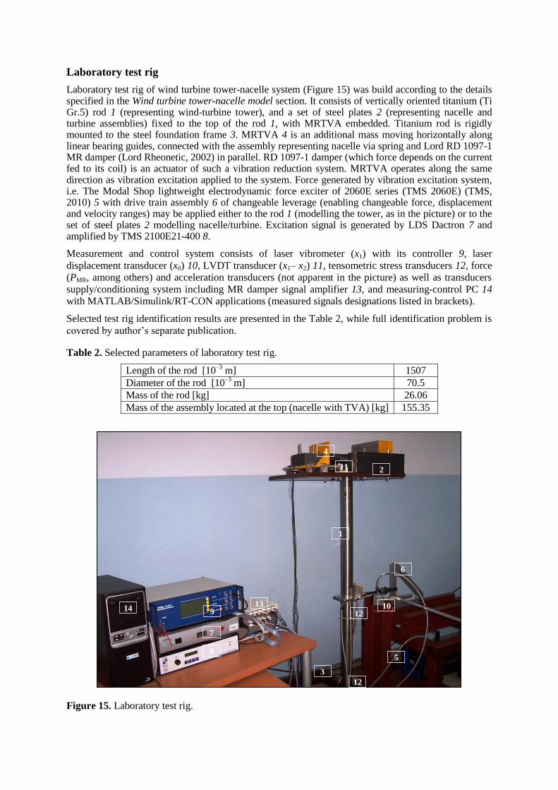
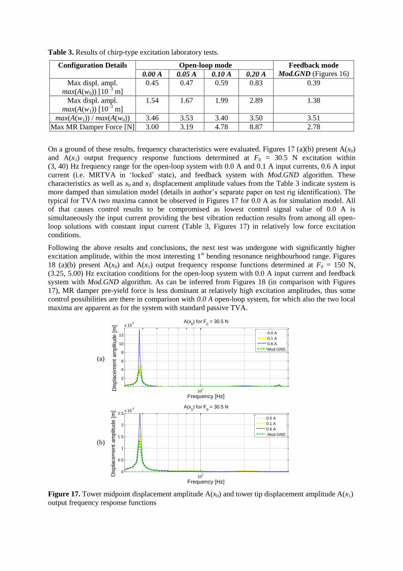
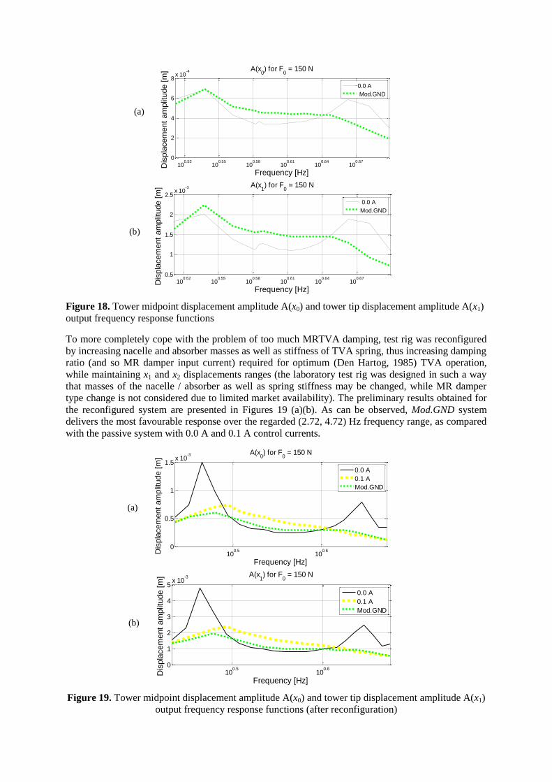
10
05210
05510
05810
06110
06410
0670
2
4
6
8x 10
-4
Frequency [Hz]
Dis
pla
cem
ent
am
plit
ude [
m] A(x
0) for F
0 = 150 N
00 A
ModGND
10
05210
05510
05810
06110
06410
06705
1
15
2
25x 10
-3
Frequency [Hz]
Dis
pla
cem
ent
am
plit
ude [
m] A(x
1) for F
0 = 150 N
00 A
ModGND
Figure 18 Tower midpoint displacement amplitude A(x0) and tower tip displacement amplitude A(x1)
output frequency response functions
To more completely cope with the problem of too much MRTVA damping test rig was reconfigured
by increasing nacelle and absorber masses as well as stiffness of TVA spring thus increasing damping
ratio (and so MR damper input current) required for optimum (Den Hartog 1985) TVA operation
while maintaining x1 and x2 displacements ranges (the laboratory test rig was designed in such a way
that masses of the nacelle absorber as well as spring stiffness may be changed while MR damper
type change is not considered due to limited market availability) The preliminary results obtained for
the reconfigured system are presented in Figures 19 (a)(b) As can be observed ModGND system
delivers the most favourable response over the regarded (272 472) Hz frequency range as compared
with the passive system with 00 A and 01 A control currents
1005
1006
0
05
1
15x 10
-3
Frequency [Hz]
Dis
pla
cem
ent
am
plit
ude [
m]
A(x0) for F
0 = 150 N
00 A
01 A
ModGND
1005
1006
0
1
2
3
4
5x 10
-3
Frequency [Hz]
Dis
pla
cem
ent
am
plit
ude [
m]
A(x1) for F
0 = 150 N
00 A
01 A
ModGND
Figure 19 Tower midpoint displacement amplitude A(x0) and tower tip displacement amplitude A(x1)
output frequency response functions (after reconfiguration)
(a)
(b)
(a)
(b)
Conclusion
The conducted comprehensive simulation study delivers a lot of valuable data concerning vibration reduction of tower-nacelle model with MRTVA Vibration control results for the system equipped with MRTVA are improved in relation with the system that emulates standard TVA with linear (viscous) damper ComsolSimulink co-simulation tool is a good solution for control algorithms analysis prototyping and implementation for continuous and continuous-discrete systems however computational time is quite a problem
The results of simulation analyses along with calculations concerning dynamic similarity of the proposed model with Vensys 82 real-world wind turbine (Snamina and Martynowicz 2014 Snamina et al 2014) served for estimation of the benefits of implementation of MRTVA for a full-scale structure These include possible reduction of structure overall mass significant reduction of tower deflection (thus bending fatigue) and nacelle acceleration amplitudes as well as possible operation at higher RPM to increase power production and decrease cost of energy factor while reducing risk of structure failure due to wind waves or earthquake induced vibration The cost analysis however is nor subject of current research project
Previous section results proved the laboratory test rig was more damped than simulation model and that compromised control possibilities as minimum control signal for feedback system (00 A) was providing the best vibration reduction results in open-loop case for low excitation amplitudes (F0 = 305 N and F0 = 346 N) To cope with that problem excitation amplitude was increased (F0 = 150 N) and test rig was reconfigured Some preliminary laboratory-based validation results of new laboratory validation tests are presented here while their full scope is covered by the separate papers (Martynowicz 2015 Rosoacuteł and Martynowicz 2015)
Further work program includes wide cooperation on implementation of such designed MRTVA system in the full scale structure within the scope of EU project
Acknowledgment
This work was financed by the Polish National Science Centre project no 2286BT02201140
References
Bak C Bitsche R Yde A Kim T Hansen MH Zahle F Gaunaa M Blasques J Dossing M Wedel-
Heinen JJ and Behrens T (2012) Light Rotor The 10-MW reference wind turbine In European Wind
Energy Association Annual Event 16ndash19042012 Copenhagen Denmark
Butt UA and Ishihara T (2012) Seismic Load Evaluation of Wind Turbine Support Structures
Considering Low Structural Damping and Soil Structure Interaction In European Wind Energy
Association Annual Event 16ndash19042012 Copenhagen Denmark
Den Hartog JP (1985) Mechanical Vibrations Mineola Dover Publications
Enevoldsen I and Mork KJ (1996) Effects of Vibration Mass Damper in a Wind Turbine Tower Mech
Struct amp Mach 24(2) 155ndash187
Hansen MH Fuglsang P Thomsen K and Knudsen T (2012) Two Methods for Estimating Aeroelastic
Damping of Operational Wind Turbine Modes from Experiments In European Wind Energy
Association Annual Event 16ndash19042012 Copenhagen Denmark
Jain P (2011) Wind Energy Engineering McGRAW-HILL
Jelavić M Perić N and Petrović I (2007) Damping of Wind Turbine Tower Oscillations through Rotor
Speed Control In International Conference on Ecologic Vehicles amp Renewable Energies March 29ndash
April 1 2007 Monaco
Kciuk S and Martynowicz P (2011) Special application magnetorheological valve numerical and
experimental analysis Control engineering in materials processing Diffusion and Defect Data ndash Solid
State Data Pt B Solid State Phenomena Vol 177 102ndash115
Kirkegaard PH Nielsen SRK Poulsen BL Andersen J Pedersen LH and Pedersen BJ (2002)
Semiactive vibration control of a wind turbine tower using an MR damper In Grundmann H and
Schueller GI (eds) Struct Dynamics EURODYN Lisse Swets amp Zeitlinger
Koo JH and Ahmadian M (2007) Qualitative Analysis of Magneto-Rheological Tuned Vibration
Absorbers Experimental Approach Journal of Intelligent Material Systems and Structures Vol 18
December 2007
Laalej H Lang ZQ Sapinski B and Martynowicz P (2012) MR damper based implementation of
nonlinear damping for a pitch plane suspension system Smart Materials and Structures Vol 21
Lord Rheonetic (2002) MR Controllable Friction Damper RD-1097-01 Product Bulletin
Łatas W and Martynowicz P (2012) Modelowanie drgań układu maszt-gondola elektrowni wiatrowej
z tłumikiem dynamicznym Modelowanie Inżynierskie nr 44 t 13 187ndash198
Martynowicz P (2014a) Development of Laboratory Model of Wind Turbines Tower-Nacelle System
with Magnetorheological Tuned Vibration Absorber Solid State Phenomena Vol 208 40ndash51
Martynowicz P (2014b) Wind turbines tower-nacelle model with magnetorheological tuned vibration
absorber ndash numerical and experimental analysis In 6WCSCM Sixth World Conference on Structural
Control and Monitoring ndash proceedings of the 6th edition of the World conference of the International
Association for Structural Control and Monitoring (IACSM) Barcelona Spain 15ndash17 July 2014
Martynowicz P (2015) Study of vibration control using laboratory test rig of wind turbinersquos tower-
nacelle system with MR damper based tuned vibration absorber Bulletin of the Polish Academy of
Sciences Technical Sciences (in review)
Martynowicz P and Szydło Z (2013) Wind turbines tower-nacelle model with magnetorheological
tuned vibration absorber the laboratory test rig In Proceedings of the 14th International Carpathian
Control Conference (ICCC) Rytro Poland May 26ndash29 2013
Maślanka M Sapiński B and Snamina J (2007) Experimental Study of Vibration Control of a Cable
With an Attached MR Damper Journal of Theoretical and Applied Mechanics 45 4 893ndash917
Warsaw
Matachowski F and Martynowicz P (2012) Analiza dynamiki konstrukcji elektrowni wiatrowej z
wykorzystaniem środowiska Comsol Multiphysics Modelowanie Inżynierskie nr 44 t 13 209ndash216
Namik H and Stol K (2011) Performance analysis of individual blade pitch control of offshore wind
turbines on two floating platforms Mechatronics 21 691ndash703
Neelakantan VA and Washington GN (2008) Vibration Control of Structural Systems using MR
dampers and a lsquoModifiedrsquo Sliding Mode Control Technique Journal of Intelligent Material Systems
and Structures Vol 19
Oh S and Ishihara T (2013) A Study on Structure Parameters of an Offshore Wind Turbine by
Excitation test Using Active Mass Damper In EWEA Offshore 19-21112013 Frankfurt
Rosoacuteł M and Martynowicz P (2015) Identification of Laboratory Model of Wind Turbinersquos Tower-
Nacelle System with MR Damper Based Tuned Vibration Absorber Mechanical Systems and Signal
Processing (in review)
Rotea MA Lackner MA and Saheba R (2010) Active Structural Control of Offshore Wind turbines
In 48th AIAA Aerospace Sciences Meeting Including the New Horizons Forum and Aerospace
Exposition 4ndash7 January 2010 Orlando Florida
Sapiński B (2008) Real-time control of magnetorheological dampers in mechanical systems Cracow
AGH University of Science and Technology Press
Sapiński B and Rosoacuteł M (2008) Autonomous control system for a 3 DOF pitch-plane suspension
system with MR shock absorbers Computers and Structures 86 379ndash385
Sapiński B (2011) Experimental study of a self-powered and sensing MR damper-based vibration
control system Smart Materials and Structures 20 105007
Shan W and Shan M (2012) Gain Scheduling Pitch Control Design for Active Tower Damping and 3p
Harmonic Reduction In European Wind Energy Association Annual Event 16ndash19042012
Copenhagen Denmark
Shen YJ Wang L Yang SP and Gao GS (2013) Nonlinear dynamical analysis and parameters
optimization of four semi-active on-off dynamic vibration absorbers Journal of Vibration and
Control January 2013 vol 19 no 1 143ndash160
Snamina J Martynowicz P and Łatas W (2014) Dynamic similarity of wind turbinersquos tower-nacelle
system and its scaled model Solid State Phenomena Vol 208 29ndash39
Snamina J and Martynowicz P (2014) Prediction of characteristics of wind turbines tower-nacelle
system from investigation of its scaled model In 6WCSCM Sixth World Conference on Structural
Control and Monitoring ndash proceedings of the 6th edition of the World conference of the International
Association for Structural Control and Monitoring (IACSM) Barcelona Spain 15ndash17 July 2014
TMS (2010) 60 Lbf Modal Shaker The Modal Shop Inc
Tsouroukdissian A Carcangiu CE Pineda Amo I Martin M Fischer T Kuhnle B and Scheu M
(2011) Wind Turbine Tower Load Reduction using Passive and Semiactive Dampers European Wind
Energy Association Annual Event Brussels