Embed Size (px)
Citation preview
Wind Turbine Generators
Synchronous and Doubly-Fed Induction Generators Installation and maintenance - Generic
Electric Power Generation Installation and maintenance - Generic 4736en-2018.01 / d
Wind Turbine Generators Synchronous and Doubly-Fed Induction Generators
2
COMPANY CONFIDENTIAL - DO NOT COPY without written consent.
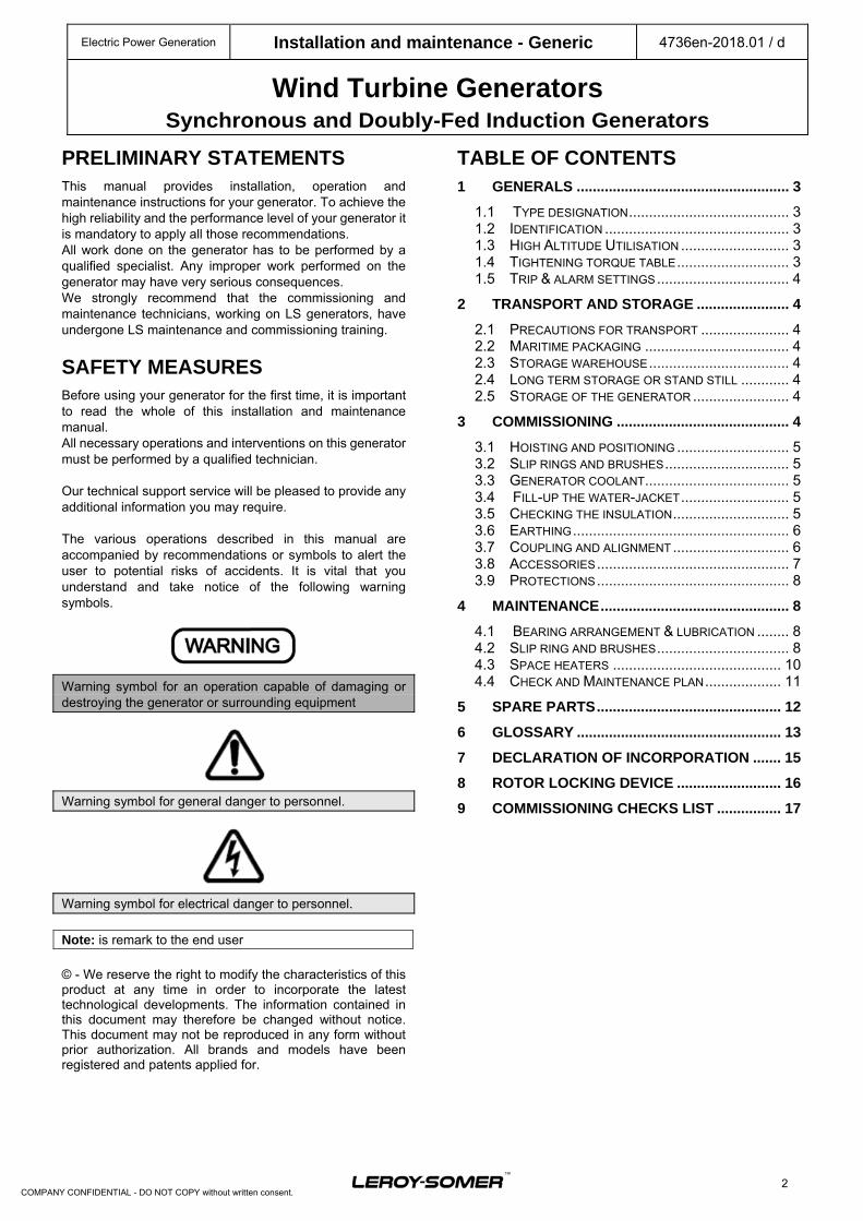
PRELIMINARY STATEMENTS This manual provides installation, operation and maintenance instructions for your generator. To achieve the high reliability and the performance level of your generator it is mandatory to apply all those recommendations. All work done on the generator has to be performed by a qualified specialist. Any improper work performed on the generator may have very serious consequences. We strongly recommend that the commissioning and maintenance technicians, working on LS generators, have undergone LS maintenance and commissioning training.
SAFETY MEASURES
Before using your generator for the first time, it is important to read the whole of this installation and maintenance manual. All necessary operations and interventions on this generator must be performed by a qualified technician. Our technical support service will be pleased to provide any additional information you may require. The various operations described in this manual are accompanied by recommendations or symbols to alert the user to potential risks of accidents. It is vital that you understand and take notice of the following warning symbols.
Warning symbol for an operation capable of damaging or destroying the generator or surrounding equipment
Warning symbol for general danger to personnel.
Warning symbol for electrical danger to personnel.
Note: is remark to the end user
© - We reserve the right to modify the characteristics of this product at any time in order to incorporate the latest technological developments. The information contained in this document may therefore be changed without notice. This document may not be reproduced in any form without prior authorization. All brands and models have been registered and patents applied for.
TABLE OF CONTENTS 1 GENERALS ..................................................... 3
1.1 TYPE DESIGNATION ........................................ 3 1.2 IDENTIFICATION .............................................. 3 1.3 HIGH ALTITUDE UTILISATION ........................... 3 1.4 TIGHTENING TORQUE TABLE ............................ 3 1.5 TRIP & ALARM SETTINGS ................................. 4
2 TRANSPORT AND STORAGE ....................... 4
2.1 PRECAUTIONS FOR TRANSPORT ...................... 4 2.2 MARITIME PACKAGING .................................... 4 2.3 STORAGE WAREHOUSE ................................... 4 2.4 LONG TERM STORAGE OR STAND STILL ............ 4 2.5 STORAGE OF THE GENERATOR ........................ 4
3 COMMISSIONING ........................................... 4
3.1 HOISTING AND POSITIONING ............................ 5 3.2 SLIP RINGS AND BRUSHES ............................... 5 3.3 GENERATOR COOLANT .................................... 5 3.4 FILL-UP THE WATER-JACKET ........................... 5 3.5 CHECKING THE INSULATION ............................. 5 3.6 EARTHING ...................................................... 6 3.7 COUPLING AND ALIGNMENT ............................. 6 3.8 ACCESSORIES ................................................ 7 3.9 PROTECTIONS ................................................ 8
4 MAINTENANCE ............................................... 8
4.1 BEARING ARRANGEMENT & LUBRICATION ........ 8 4.2 SLIP RING AND BRUSHES ................................. 8 4.3 SPACE HEATERS .......................................... 10 4.4 CHECK AND MAINTENANCE PLAN ................... 11
5 SPARE PARTS .............................................. 12
6 GLOSSARY ................................................... 13
7 DECLARATION OF INCORPORATION ....... 15
8 ROTOR LOCKING DEVICE .......................... 16
9 COMMISSIONING CHECKS LIST ................ 17
Electric Power Generation Installation and maintenance - Generic 4736en-2018.01 / d
Wind Turbine Generators Synchronous and Doubly-Fed Induction Generators
3
COMPANY CONFIDENTIAL - DO NOT COPY without written consent.
1 GENERALS
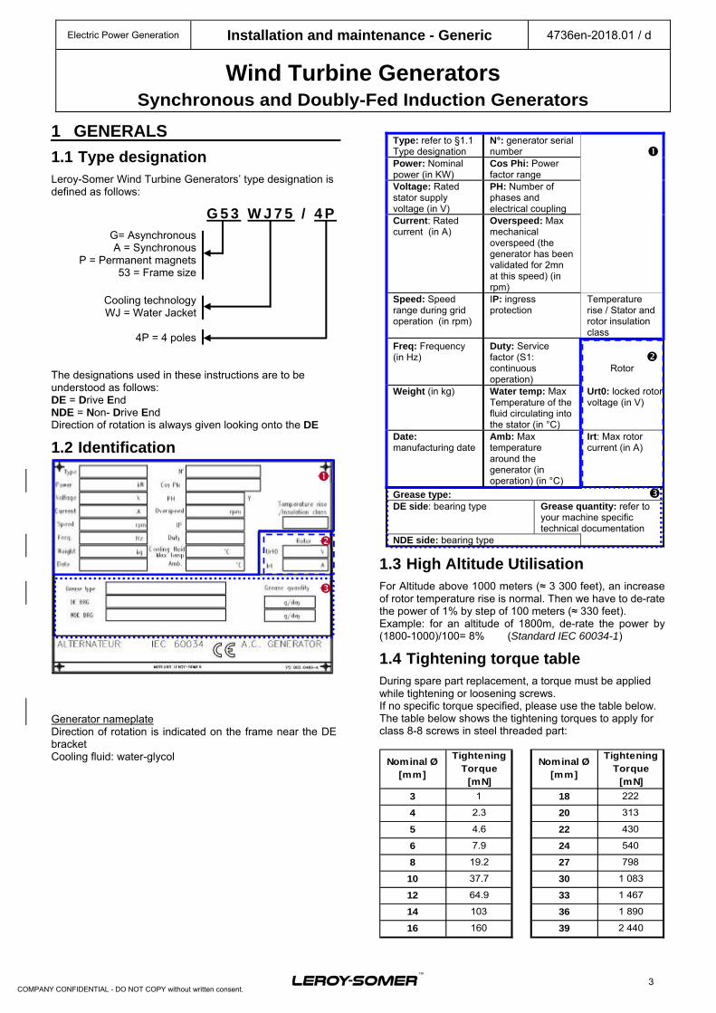
1.1 Type designation Leroy-Somer Wind Turbine Generators’ type designation is defined as follows:
G 5 3 W J 7 5 / 4 P
G= Asynchronous A = Synchronous
P = Permanent magnets 53 = Frame size
Cooling technology WJ = Water Jacket
4P = 4 poles
The designations used in these instructions are to be understood as follows: DE = Drive End NDE = Non- Drive End Direction of rotation is always given looking onto the DE
1.2 Identification
Generator nameplate Direction of rotation is indicated on the frame near the DE bracket Cooling fluid: water-glycol
Type: refer to §1.1 Type designation
N°: generator serial number
Power: Nominal power (in KW)
Cos Phi: Power factor range
Voltage: Rated stator supply voltage (in V)
PH: Number of phases and electrical coupling
Current: Rated current (in A)
Overspeed: Max mechanical overspeed (the generator has been validated for 2mn at this speed) (in rpm)
Speed: Speed range during grid operation (in rpm)
IP: ingress protection
Temperature rise / Stator and rotor insulation class
Freq: Frequency (in Hz)
Duty: Service factor (S1: continuous operation)
Rotor
Weight (in kg) Water temp: Max Temperature of the fluid circulating into the stator (in °C)
Urt0: locked rotor voltage (in V)
Date: manufacturing date
Amb: Max temperature around the generator (in operation) (in °C)
Irt: Max rotor current (in A)
Grease type: DE side: bearing type Grease quantity: refer to
your machine specific technical documentation
NDE side: bearing type
1.3 High Altitude Utilisation For Altitude above 1000 meters (≈ 3 300 feet), an increase of rotor temperature rise is normal. Then we have to de-rate the power of 1% by step of 100 meters (≈ 330 feet). Example: for an altitude of 1800m, de-rate the power by (1800-1000)/100= 8% (Standard IEC 60034-1)
1.4 Tightening torque table During spare part replacement, a torque must be applied while tightening or loosening screws. If no specific torque specified, please use the table below. The table below shows the tightening torques to apply for class 8-8 screws in steel threaded part:
Nominal Ø[mm]
Tightening Torque
[mN]
Nominal Ø[mm]
Tightening Torque
[mN]
3 1 18 222
4 2.3 20 313
5 4.6 22 430
6 7.9 24 540
8 19.2 27 798
10 37.7 30 1 083
12 64.9 33 1 467
14 103 36 1 890
16 160 39 2 440
Electric Power Generation Installation and maintenance - Generic 4736en-2018.01 / d
Wind Turbine Generators Synchronous and Doubly-Fed Induction Generators
4
COMPANY CONFIDENTIAL - DO NOT COPY without written consent.
1.5 Trip & alarm settings Recommended values for F temperature rise are as follow:
Alarm TripStator PT100 140°C 145°C
Bearings PT100 90°C 95°C
Slip ring housing 80°C 100°C
2 TRANSPORT AND STORAGE We advise you to proceed to a general inspection when receiving your generator at its final destination for any potential transport damage. If there is any damage, send a registered letter to the Transport Company with a copy of the receipt signed by incoming department and truck driver. The receipt shall mention the damages to the generator. Send a copy of the record of damage to Leroy-Somer within 3 days after reception.
2.1 Precautions for transport During transport, shocks level applied to the machine must remain below 30 m/s². The shaft locking system must be installed when the machine is transported (See appendix: Dismantling and assembly of the rotor locking device) Machine temperature must remain within the range -20°C to +50°C. The machine must be protected against bad weather conditions and condensation. The machine must not be handled at temperature below -20°C, for lifting the machine, please refer to section 3.1.
2.2 Maritime packaging In case generators are shipped by sea, a seaworthy packing hermetically sealed (Crate 4C SEI NIMP 15 Standard) will be used. Breaking the hermetic protective film discharges Leroy-Somer of its warranty.
2.3 Storage warehouse The machine must be stored in a clean and dry premise and must not be subject to abrupt temperature changes or to high humidity. Storage at an ambient temperature of +5 to +45° C is recommended. The machine must not be subject to vibrations during storage. In any case, generator must be stored empty of cooling water.
2.4 Long term storage or stand still Before stopping or storing the machine for a long period (several months), it is essential to take several precautionary measures: - The space heaters must be switched on at all times (do not forget to ground the machine). - For water-coolers, the water flow must be shut off. If the water is not treated and if there is likelihood of freezing, the exchanger must be drained. - Power brushes for DFIG and ground brushes for DFIG and SEG must be in upper position (not in contact with the ring) to avoid any marking on the slip rings.
2.5 Storage of the generator If the generator is new there is no need to refill the bearing cage with new grease. If the machine already ran for several hundreds of hours, then the used grease must be removed and replaced by new grease. To be sure that all the used grease has been totally removed, 2 volumes (refer to your specific installation and maintenance manual) of new grease must be injected via the distributor inlet.
Once it is done, store the machine for 6 months. Then every 6 months, turn the machine shaft line of few turns.
It is mandatory to place a protective foil between slip rings and brushes (earthing brushes and main brushes) or remove brushes as described in paragraph 2.4.
The grease used for re-greasing must absolutely be the one specified on the machine nameplate
Before starting the machine up again, it will be necessary to carry out a start-up inspection:
- Check the insulation – paragraph 3.3,
- Check the alignment – paragraph 3.5.2.3,
- Check the filters – paragraph 3.6.3,
- Check the protections – paragraph 3.7,
- Test that the centralized lubrication system is working properly. If generator storage period has been more than 5 months, inject slowly one grease volume per bearing (refer to your “specific installation and maintenance manual”) while the generator is rotating (at a minimum speed of 100rpm).
Note: a commissioning check list available at the end of the document
3 COMMISSIONING
Generators are industrial products. Therefore, they must be installed by qualified experienced personnel. Leroy-Somer will not assume any legal responsibility in case of non-observation of this installation and maintenance manual.
Note: a commissioning check list available at the end of the document
Electric Power Generation Installation and maintenance - Generic 4736en-2018.01 / d
Wind Turbine Generators Synchronous and Doubly-Fed Induction Generators
5
COMPANY CONFIDENTIAL - DO NOT COPY without written consent.
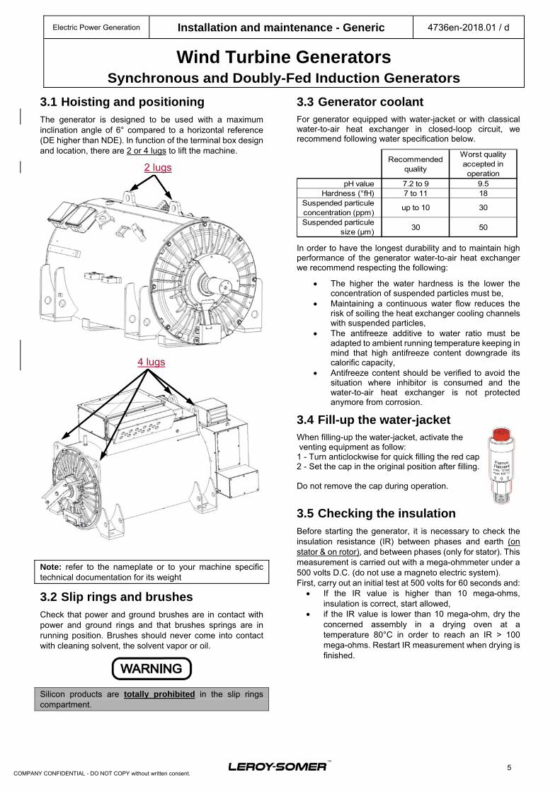
3.1 Hoisting and positioning The generator is designed to be used with a maximum inclination angle of 6° compared to a horizontal reference (DE higher than NDE). In function of the terminal box design and location, there are 2 or 4 lugs to lift the machine.
Note: refer to the nameplate or to your machine specific technical documentation for its weight
3.2 Slip rings and brushes Check that power and ground brushes are in contact with power and ground rings and that brushes springs are in running position. Brushes should never come into contact with cleaning solvent, the solvent vapor or oil.
Silicon products are totally prohibited in the slip rings compartment.
3.3 Generator coolant For generator equipped with water-jacket or with classical water-to-air heat exchanger in closed-loop circuit, we recommend following water specification below.
Recommended quality
Worst quality accepted in operation
pH value 7.2 to 9 9.5Hardness (°fH) 7 to 11 18
Suspended particule concentration (ppm)
up to 10 30
Suspended particule size (µm)
30 50
In order to have the longest durability and to maintain high performance of the generator water-to-air heat exchanger we recommend respecting the following:
The higher the water hardness is the lower the concentration of suspended particles must be,
Maintaining a continuous water flow reduces the risk of soiling the heat exchanger cooling channels with suspended particles,
The antifreeze additive to water ratio must be adapted to ambient running temperature keeping in mind that high antifreeze content downgrade its calorific capacity,
Antifreeze content should be verified to avoid the situation where inhibitor is consumed and the water-to-air heat exchanger is not protected anymore from corrosion.
3.4 Fill-up the water-jacket When filling-up the water-jacket, activate the venting equipment as follow: 1 - Turn anticlockwise for quick filling the red cap 2 - Set the cap in the original position after filling. Do not remove the cap during operation.
3.5 Checking the insulation Before starting the generator, it is necessary to check the insulation resistance (IR) between phases and earth (on stator & on rotor), and between phases (only for stator). This measurement is carried out with a mega-ohmmeter under a 500 volts D.C. (do not use a magneto electric system). First, carry out an initial test at 500 volts for 60 seconds and:
If the IR value is higher than 10 mega-ohms, insulation is correct, start allowed,
if the IR value is lower than 10 mega-ohm, dry the concerned assembly in a drying oven at a temperature 80°C in order to reach an IR > 100 mega-ohms. Restart IR measurement when drying is finished.
2 lugs
4 lugs
Electric Power Generation Installation and maintenance - Generic 4736en-2018.01 / d
Wind Turbine Generators Synchronous and Doubly-Fed Induction Generators
6
COMPANY CONFIDENTIAL - DO NOT COPY without written consent.
If the generator cannot be placed in a drying oven: Connect the generator to a 3-phases A.C voltage
source reduced to approximately 10% of the rated voltage (Un x 0.1) for 12 hours (use an induction regulator or a reduction transformer with adjustable outlets).
Nota: Check that the stator PT100 sensors temperature remains below 100°C
The A.C current will be monitored via a clamp-on ammeter.
While drying, all generator orifices must be opened (terminal box, drain holes).
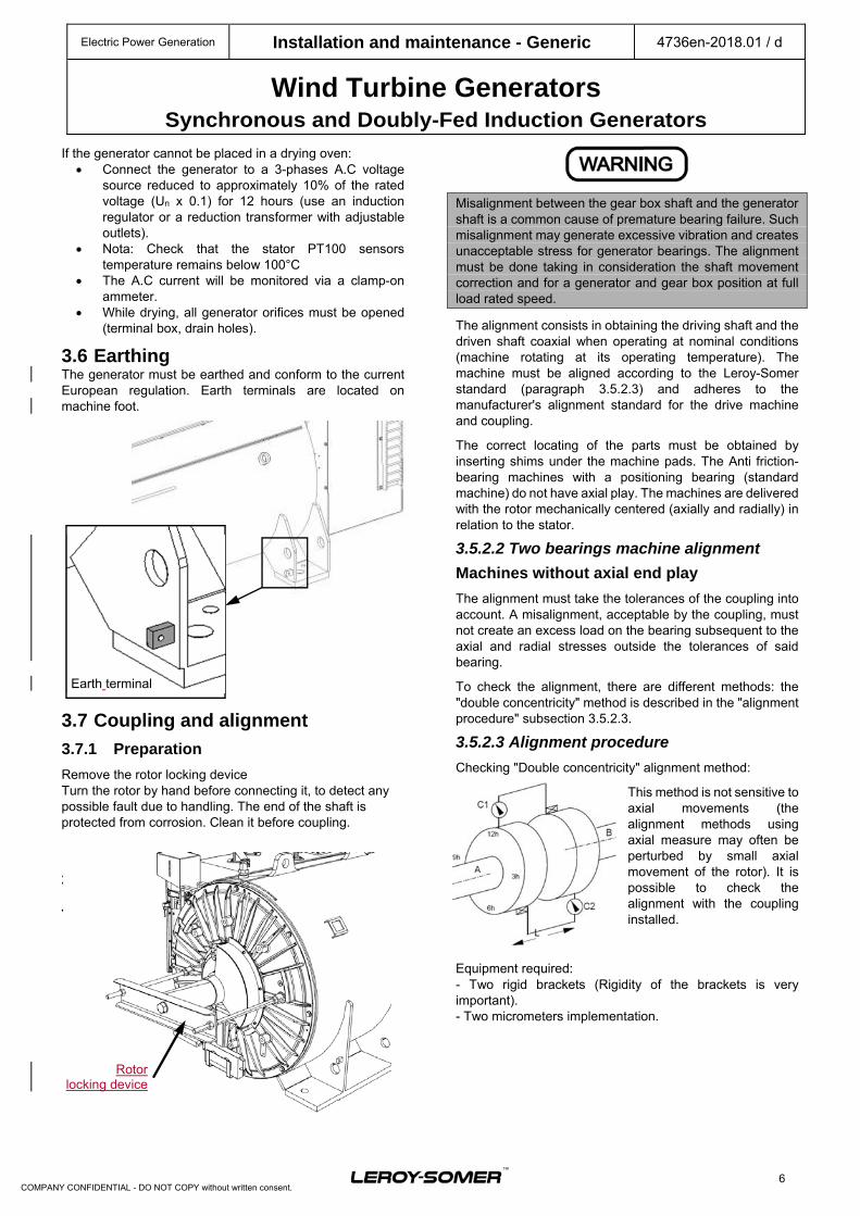
3.6 Earthing The generator must be earthed and conform to the current European regulation. Earth terminals are located on machine foot.
3.7 Coupling and alignment
3.7.1 Preparation
Remove the rotor locking device Turn the rotor by hand before connecting it, to detect any possible fault due to handling. The end of the shaft is protected from corrosion. Clean it before coupling.
3.7.2 Machine alignment
3.5.2.1 Alignment general points
Misalignment between the gear box shaft and the generator shaft is a common cause of premature bearing failure. Such misalignment may generate excessive vibration and creates unacceptable stress for generator bearings. The alignment must be done taking in consideration the shaft movement correction and for a generator and gear box position at full load rated speed.
The alignment consists in obtaining the driving shaft and the driven shaft coaxial when operating at nominal conditions (machine rotating at its operating temperature). The machine must be aligned according to the Leroy-Somer standard (paragraph 3.5.2.3) and adheres to the manufacturer's alignment standard for the drive machine and coupling.
The correct locating of the parts must be obtained by inserting shims under the machine pads. The Anti friction-bearing machines with a positioning bearing (standard machine) do not have axial play. The machines are delivered with the rotor mechanically centered (axially and radially) in relation to the stator.
3.5.2.2 Two bearings machine alignment
Machines without axial end play
The alignment must take the tolerances of the coupling into account. A misalignment, acceptable by the coupling, must not create an excess load on the bearing subsequent to the axial and radial stresses outside the tolerances of said bearing.
To check the alignment, there are different methods: the "double concentricity" method is described in the "alignment procedure" subsection 3.5.2.3.
3.5.2.3 Alignment procedure
Checking "Double concentricity" alignment method:
This method is not sensitive to axial movements (the alignment methods using axial measure may often be perturbed by small axial movement of the rotor). It is possible to check the alignment with the coupling installed.
Equipment required: - Two rigid brackets (Rigidity of the brackets is very important). - Two micrometers implementation.
Earth terminal
Rotor locking device
Electric Power Generation Installation and maintenance - Generic 4736en-2018.01 / d
Wind Turbine Generators Synchronous and Doubly-Fed Induction Generators
7
COMPANY CONFIDENTIAL - DO NOT COPY without written consent.
During the measures, both shafts must turn simultaneously in the same direction. (For example: the coupling installed with its screws loosened). By turning both shafts simultaneously, the measurement isn’t affected by the error resulting from the two shaft ends run out.
Note: below interpretation of measurements are for example
Measurements:
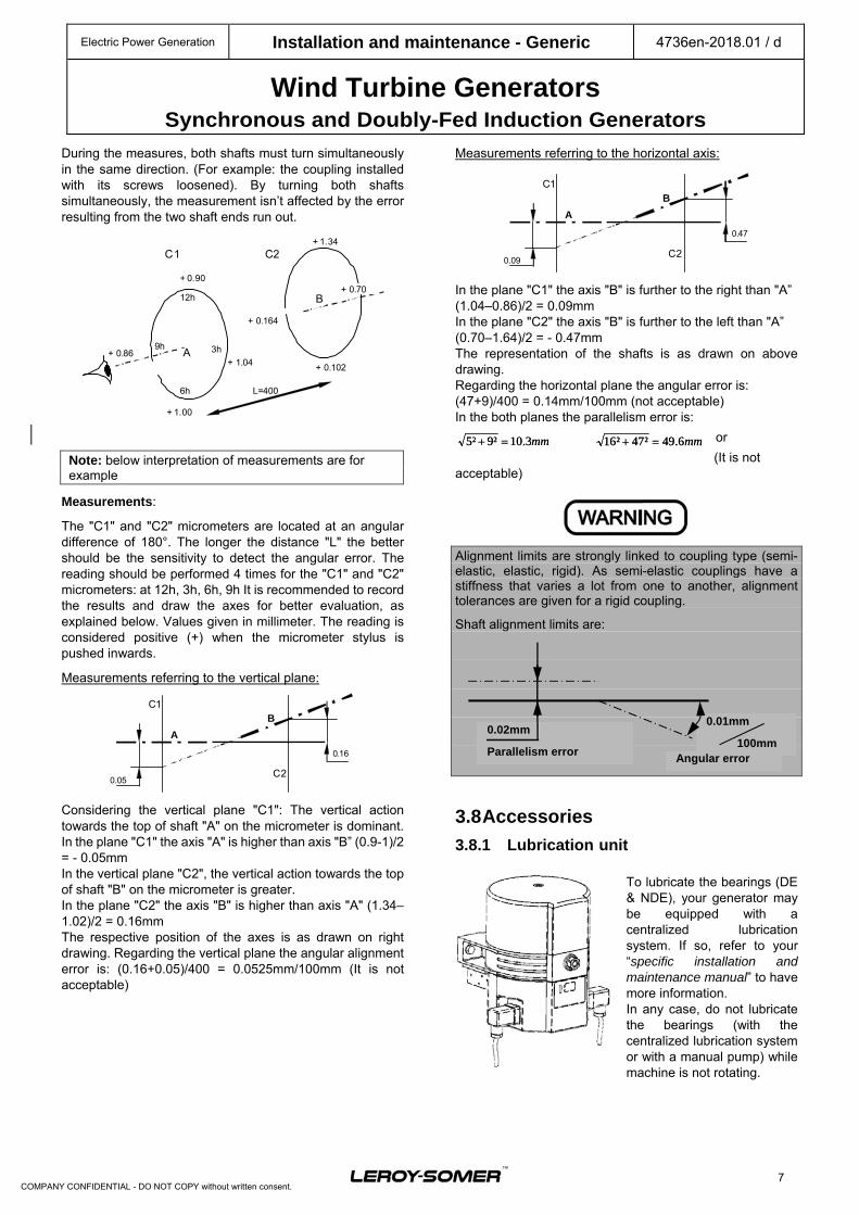
The "C1" and "C2" micrometers are located at an angular difference of 180°. The longer the distance "L" the better should be the sensitivity to detect the angular error. The reading should be performed 4 times for the "C1" and "C2" micrometers: at 12h, 3h, 6h, 9h It is recommended to record the results and draw the axes for better evaluation, as explained below. Values given in millimeter. The reading is considered positive (+) when the micrometer stylus is pushed inwards.
Measurements referring to the vertical plane:
Considering the vertical plane "C1": The vertical action towards the top of shaft "A" on the micrometer is dominant. In the plane "C1" the axis "A" is higher than axis "B” (0.9-1)/2 = - 0.05mm In the vertical plane "C2", the vertical action towards the top of shaft "B" on the micrometer is greater. In the plane "C2" the axis "B" is higher than axis "A" (1.34–1.02)/2 = 0.16mm The respective position of the axes is as drawn on right drawing. Regarding the vertical plane the angular alignment error is: (0.16+0.05)/400 = 0.0525mm/100mm (It is not acceptable)
Measurements referring to the horizontal axis:
In the plane "C1" the axis "B" is further to the right than "A” (1.04–0.86)/2 = 0.09mm In the plane "C2" the axis "B" is further to the left than "A” (0.70–1.64)/2 = - 0.47mm The representation of the shafts is as drawn on above drawing. Regarding the horizontal plane the angular error is: (47+9)/400 = 0.14mm/100mm (not acceptable) In the both planes the parallelism error is:
or
(It is not acceptable)
Alignment limits are strongly linked to coupling type (semi-elastic, elastic, rigid). As semi-elastic couplings have a stiffness that varies a lot from one to another, alignment tolerances are given for a rigid coupling.
Shaft alignment limits are:
3.8 Accessories
3.8.1 Lubrication unit
To lubricate the bearings (DE & NDE), your generator may be equipped with a centralized lubrication system. If so, refer to your “specific installation and maintenance manual” to have more information. In any case, do not lubricate the bearings (with the centralized lubrication system or with a manual pump) while machine is not rotating.
mm3.10²9²5 mm6.49²47²16
0.01mm
100mm Angular error
0.02mm
Parallelism error
A
B C1
C2 0.09
0.47
A
B C1
C2 0.05
0.16
mm3.10²9²5 mm6.49²47²16
C1 C2
A
B
3h 9h
12h
6h
+ 0.90
+ 1.04
+ 1.34
+ 1.00
+ 0.86
+ 0.164
+ 0.102
+ 0.70
L=400
Electric Power Generation Installation and maintenance - Generic 4736en-2018.01 / d
Wind Turbine Generators Synchronous and Doubly-Fed Induction Generators
8
COMPANY CONFIDENTIAL - DO NOT COPY without written consent.
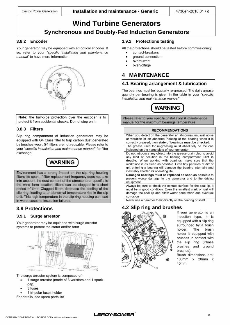
3.8.2 Encoder
Your generator may be equipped with an optical encoder. If so, refer to your “specific installation and maintenance manual” to have more information.
Note: the half-pipe protection over the encoder is to protect it from accidental shocks. Do not step on it.
3.8.3 Filters Slip ring compartment of induction generators may be equipped with G4 Class filter to trap carbon dust generated by brushes wear. G4 filters are not reusable. Please refer to your “specific installation and maintenance manual” for filter exchange.
Environment has a strong impact on the slip ring housing filters life span. If filter replacement frequency does not take into account the dust content of the atmosphere, specific to the wind farm location, filters can be clogged in a short period of time. Clogged filters decrease the cooling of the slip ring, leading to an abnormal temperature rise in the slip unit. This high temperature in the slip ring housing can lead in worst cases to insulation failures.
3.9 Protections 3.9.1 Surge arrestor
Your generator may be equipped with surge arrestor systems to protect the stator and/or rotor.
The surge arrestor system is composed of: 1 surge arrestor (made of 3 varistors and 1 spark
gap) 3 fuses 1 tri-polar fuses holder
For details, see spare parts list
3.9.2 Protections testing
All the protections should be tested before commissioning: contact-breakers ground connection overcurrent overvoltage
4 MAINTENANCE
4.1 Bearing arrangement & lubrication
The bearings must be regularly re-greased. The daily grease quantity per bearing is given in the table in your “specific installation and maintenance manual”.
Please refer to your specific installation & maintenance manual for the maximum bearings temperature
RECOMMENDATIONS When you detect on the generator an abnormal/ unusual noise or vibration or an abnormal heating of the bearing when it is correctly greased, then state of bearings must be checked.The grease used for re-greasing must absolutely be the one indicated on the name plate of your generator. Do not introduce any object into the grease drain plug to avoid any kind of pollution in the bearing compartment. Dirt is deadly. When working with bearings, make sure that the workplace is as clean as possible. Even tiny particles of dirt or grit entering a bearing will damage the bearing internally and inevitably shorten its operating life. Damaged bearings must be replaced as soon as possible to prevent worse damage to the generator and to the driving equipment.Always be sure to check the contact surface for the seal lip. It must be in good condition. Even the smallest mark or rust will damage the seal lip and allow water penetration and eventual corrosionNever use a hammer to hit directly on the bearing or shaft
4.2 Slip ring and brushes If your generator is an induction type, it is equipped with a slip ring surrounded by a brush holder. The brush holder is equipped with brushes in contact with the slip ring (Phase brushes and ground brushes). Brush dimensions are: 100mm x 20mm x 40mm
Electric Power Generation Installation and maintenance - Generic 4736en-2018.01 / d
Wind Turbine Generators Synchronous and Doubly-Fed Induction Generators
9
COMPANY CONFIDENTIAL - DO NOT COPY without written consent.
4.2.1 Slip rings, brushes and brush holder cleaning method
Changing the brushes while the generator is running is extremely dangerous for both personnel and generator. Therefore, brushes must only be changed when the generator is switched off and at rest.
Remove all brushes before beginning with the cleaning work. Brushes, brush-holder and slip ring are best cleaned of carbon dust with a vacuum cleaner. Mechanical dry cleaning should always be the preferred cleaning method. Only vacuum cleaners with soft suction nozzles made of rubber or plastic should be used. Use a brush to wipe clean and push the carbon dust towards the vacuum cleaner nozzle. On the slip rings, the developed patina (refer to definition below) must not be destroyed by unnecessary grinding or hand stoning, not even when replacing the brushes, it should stay completely untouched.
Brushes should never come into contact with cleaning solvent, solvent vapor or oil. Silicon products are totally prohibited in the slip rings compartment.
What is patina? Patina, or skin, which plays such an important part in brush behaviour, must not be regarded as static: it is something alive and constantly changing under effects of opposing factors, some building it up and others destroying it. Under the majority of given operating conditions a dynamic equilibrium is reached when the skin thinning and the skin recovery process balance. The colour of the patina is largely an effect of thickness. The patina appearance depends mostly upon the brush grade in use and upon the brush electrical load. Irregularities in the skin formation arise from electrical or mechanical faults and can therefore be used in diagnosing troubles. If the slip ring temperature, brush temperature and air humidity are correct, a patina will be built up automatically.
4.2.2 Brush wear
Brush wear shall be around 2mm to 5mm per 1000 hours with a 65% of relative humidity. In case of a hygrometry below 30% of relative humidity, be aware that the brushes could wear faster. Brushes must be changed as soon as one brush length reaches 30mm (i.e. when 70% of total length is worn). Please note that ground brushes wear a little bit faster than power brushes. Brush wear detectors will detect when one brush has reached its signal length. It is mandatory to change all the brushes when one is worn. The brush gear should be blown out occasionally and the brushes must always slide freely in their brush gear.
The minimum remaining length must always exceed 20mm. It is mandatory to change all brushes when one is worn to its limit.
4.2.3 Brush change
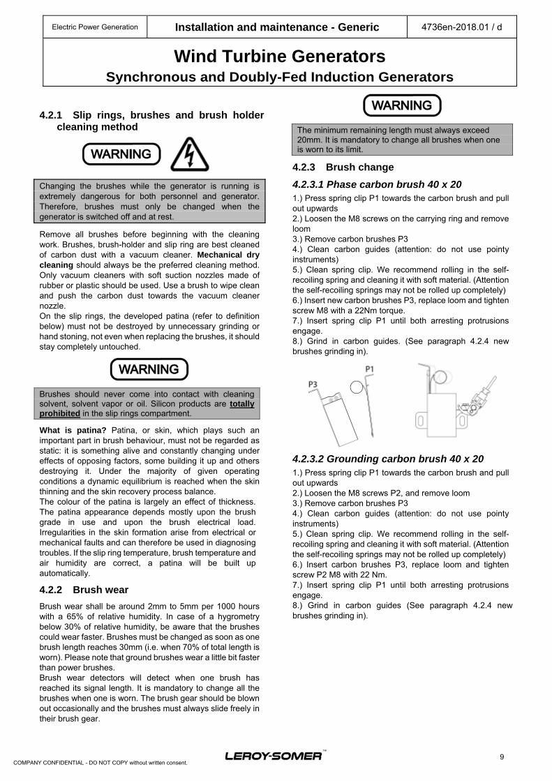
4.2.3.1 Phase carbon brush 40 x 20 1.) Press spring clip P1 towards the carbon brush and pull out upwards 2.) Loosen the M8 screws on the carrying ring and remove loom 3.) Remove carbon brushes P3 4.) Clean carbon guides (attention: do not use pointy instruments) 5.) Clean spring clip. We recommend rolling in the self-recoiling spring and cleaning it with soft material. (Attention the self-recoiling springs may not be rolled up completely) 6.) Insert new carbon brushes P3, replace loom and tighten screw M8 with a 22Nm torque. 7.) Insert spring clip P1 until both arresting protrusions engage. 8.) Grind in carbon guides. (See paragraph 4.2.4 new brushes grinding in).
4.2.3.2 Grounding carbon brush 40 x 20 1.) Press spring clip P1 towards the carbon brush and pull out upwards 2.) Loosen the M8 screws P2, and remove loom 3.) Remove carbon brushes P3 4.) Clean carbon guides (attention: do not use pointy instruments) 5.) Clean spring clip. We recommend rolling in the self-recoiling spring and cleaning it with soft material. (Attention the self-recoiling springs may not be rolled up completely) 6.) Insert carbon brushes P3, replace loom and tighten screw P2 M8 with 22 Nm. 7.) Insert spring clip P1 until both arresting protrusions engage. 8.) Grind in carbon guides (See paragraph 4.2.4 new brushes grinding in).
Electric Power Generation Installation and maintenance - Generic 4736en-2018.01 / d
Wind Turbine Generators Synchronous and Doubly-Fed Induction Generators
10
COMPANY CONFIDENTIAL - DO NOT COPY without written consent.
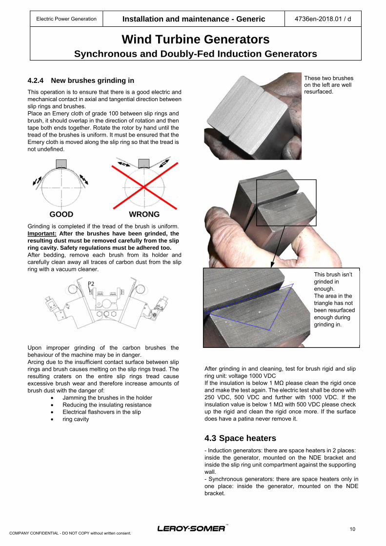
4.2.4 New brushes grinding in
This operation is to ensure that there is a good electric and mechanical contact in axial and tangential direction between slip rings and brushes. Place an Emery cloth of grade 100 between slip rings and brush, it should overlap in the direction of rotation and then tape both ends together. Rotate the rotor by hand until the tread of the brushes is uniform. It must be ensured that the Emery cloth is moved along the slip ring so that the tread is not undefined.
Grinding is completed if the tread of the brush is uniform. Important: After the brushes have been grinded, the resulting dust must be removed carefully from the slip ring cavity. Safety regulations must be adhered too. After bedding, remove each brush from its holder and carefully clean away all traces of carbon dust from the slip ring with a vacuum cleaner.
Upon improper grinding of the carbon brushes the behaviour of the machine may be in danger. Arcing due to the insufficient contact surface between slip rings and brush causes melting on the slip rings tread. The resulting craters on the entire slip rings tread cause excessive brush wear and therefore increase amounts of brush dust with the danger of:
Jamming the brushes in the holder Reducing the insulating resistance Electrical flashovers in the slip ring cavity
After grinding in and cleaning, test for brush rigid and slip ring unit: voltage 1000 VDC If the insulation is below 1 MΩ please clean the rigid once and make the test again. The electric test shall be done with 250 VDC, 500 VDC and further with 1000 VDC. If the insulation value is below 1 MΩ with 500 VDC please check up the rigid and clean the rigid once more. If the surface does have a patina never remove it.
4.3 Space heaters - Induction generators: there are space heaters in 2 places: inside the generator, mounted on the NDE bracket and inside the slip ring unit compartment against the supporting wall. - Synchronous generators: there are space heaters only in one place: inside the generator, mounted on the NDE bracket.
These two brushes on the left are well resurfaced.
WRONG GOOD
Electric Power Generation Installation and maintenance - Generic 4736en-2018.01 / d
Wind Turbine Generators Synchronous and Doubly-Fed Induction Generators
11
COMPANY CONFIDENTIAL - DO NOT COPY without written consent.
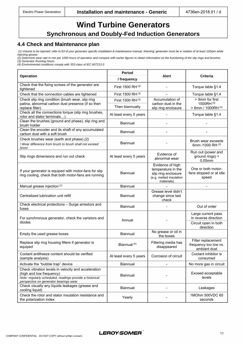
4.4 Check and Maintenance plan (1) Volume to be injected: refer to §3 of your generator specific installation & maintenance manual. Warning: generator must be in rotation of at least 100rpm while injecting grease (2) Determine wear rate in mm per 1000 hours of operation and compare with earlier figures to obtain information on the functioning of the slip rings and brushes. (3) Generator Running Hours (4) Environmental conditions comply with 3S3 class of IEC 607213-3
Operation Period
Alert Criteria / frequency
Check that the fixing screws of the generator are tightened
First 1500 RH (3) - Torque table §1.4
Check that the connection cables are tightened First 1500 RH (3) - Torque table §1.4
Check slip ring condition (brush wear, slip ring patina, abnormal carbon dust presence (if so then replace filter)
First 1500 RH (3) Accumulation of carbon dust in the slip ring enclosure
> 9mm for first 1500RH (3)
> 6mm / 1000RH (3)Then biannually
Check all the connections torque (slip ring brushes, rotor and stator terminals…)
At least every 5 years - Torque table §1.4
Clean the brushes (ground and phase), slip ring and brush holder
Biannual - -
Clean the encoder and its shaft of any accumulated carbon dust with a soft brush
Biannual - -
Check brushes wear (earth and phase) (2) Biannual -
Brush wear exceeds 6mm /1000 RH (3) ! Wear difference from brush to brush shall not exceed
5mm!
Slip rings dimensions and run out check At least every 5 years Evidence of
abnormal wear
Run out (power and ground rings) <
0.05mm
If your generator is equiped with motor-fans for slip ring cooling, check that both motor-fans are running
Biannual
Evidence of high temperature in the slip ring enclosure
(e.g. melted insulation materials)
One or both motor-fans stopped or at idle
speed
Manual grease injection (1) Biannual - -
Centralized lubrication unit refill Biannual Grease level didn’t change since last
check
Check electrical protections – Surge arrestors and fuses
Biannual - Out of order
For synchronous generator, check the varistors and diodes
Annual -
Large current pass in reverse direction Circuit open in both
direction
Empty the used grease boxes Biannual No grease or oil in
the boxes
Replace slip ring housing filters if generator is equiped
Biannual (4) Filtering media has
disappeared
Filter replacement frequency too low vs.
ambiant dustCoolant antifreeze content should be verified (sample analysis)
At least every 5 years Corrosion of circuit Coolant inhibitor is
consumed
Activate the “bubble trap” device Biannual - No more gas in circuit
Check vibration levels in velocity and acceleration (high and low frequency) Biannual -
Exceed acceptable levels Note: regularly scheduled, readings provide a historical
perspective on generator bearings wear Check visually any liquids leakages (grease and cooling liquid)
Biannual - Leakages
Check the rotor and stator insulation resistance and the polarization index
Yearly - 1MOhm 500VDC 60
seconds
Electric Power Generation Installation and maintenance - Generic 4736en-2018.01 / d
Wind Turbine Generators Synchronous and Doubly-Fed Induction Generators
12
COMPANY CONFIDENTIAL - DO NOT COPY without written consent.
5 SPARE PARTS Spare parts can be ordered by contacting the following department:
Leroy-Somer - EMEA Spare parts department
1, rue de la Burelle 45800 Saint Jean de Braye
FRANCE [email protected]
Tel.: +33 2 38 60 42 80
The following will VOID warranty: - Damage due to improper transportation, - Failure to respect storage procedure, to perform the proper commissioning procedure, to service the generator as recommended in the installation and maintenance manuals (generic and specific to the generator), - Repairs and/or adjustments by anyone other than an authorized service person trained by Leroy-Somer, - Use of parts not sold or approved by Leroy-Somer, - Negligence and abuse of the generator.
Leroy-Somer - INDIA #45, Nagarur, Huskur Road,
Off Tumkur Road, Bangalore – 562 162
INDIA [email protected]
Tel.: +91 806 726 4867
Leroy-Somer - ASIA 1 Emerson Road, Gaishan town,
Cangshan District, 350026 Fuzhou
CHINA [email protected]
Tel.: +86 591 883 730 36
Electric Power Generation Installation and maintenance - Generic 4736en-2018.01 / d
Wind Turbine Generators Synchronous and Doubly-Fed Induction Generators
13
COMPANY CONFIDENTIAL - DO NOT COPY without written consent.
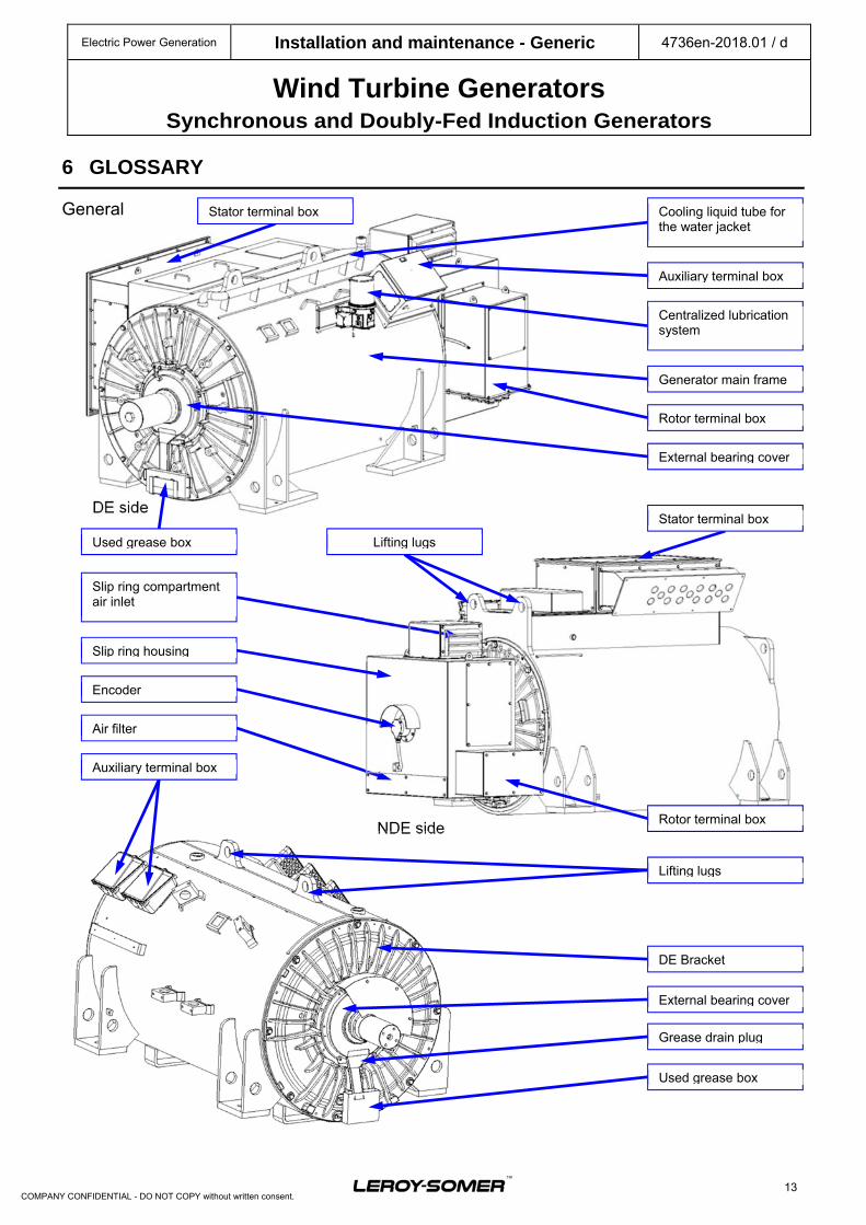
DE side
NDE side
Used grease box
Slip ring housing
Air filter
Encoder
Slip ring compartment air inlet
Lifting lugs
Auxiliary terminal box
Stator terminal box
Centralized lubrication system
Generator main frame
Auxiliary terminal box
Cooling liquid tube for the water jacket
Rotor terminal box
Stator terminal box
DE Bracket
Grease drain plug
Used grease box
External bearing cover
Lifting lugs
External bearing cover
Rotor terminal box
6 GLOSSARY
General
Electric Power Generation Installation and maintenance - Generic 4736en-2018.01 / d
Wind Turbine Generators Synchronous and Doubly-Fed Induction Generators
14
COMPANY CONFIDENTIAL - DO NOT COPY without written consent.
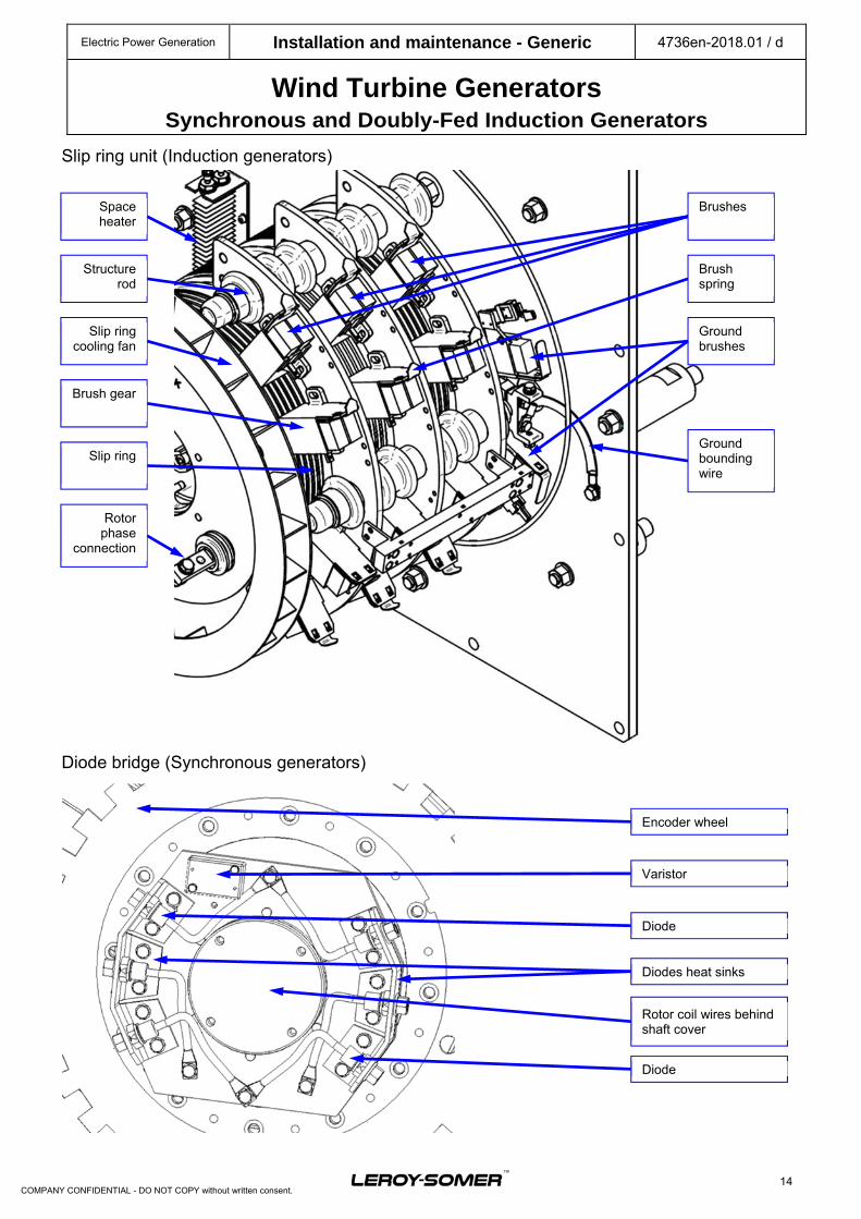
Slip ring unit (Induction generators)
Diode bridge (Synchronous generators)
Space heater
Structure rod
Slip ring cooling fan
Brush gear
Slip ring
Rotor phase
connection
Brushes
Brush spring
Ground brushes
Ground bounding wire
Diode
Diodes heat sinks
Encoder wheel
Rotor coil wires behind shaft cover
Varistor
Diode
Electric Power Generation Installation and maintenance - Generic 4736en-2018.01 / d
Wind Turbine Generators Synchronous and Doubly-Fed Induction Generators
15
COMPANY CONFIDENTIAL - DO NOT COPY without written consent.
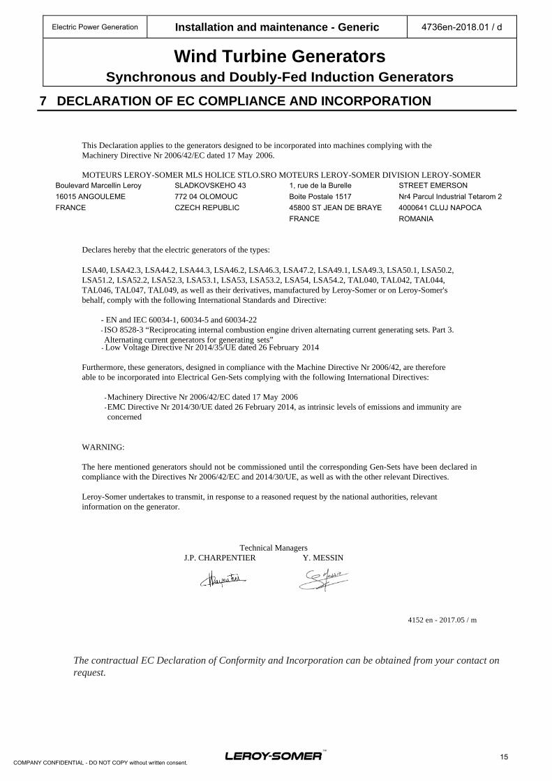
7 DECLARATION OF EC COMPLIANCE AND INCORPORATION
This Declaration applies to the generators designed to be incorporated into machines complying with the Machinery Directive Nr 2006/42/EC dated 17 May 2006.
MOTEURS LEROY-SOMER MLS HOLICE STLO.SRO MOTEURS LEROY-SOMER DIVISION LEROY-SOMER
Boulevard Marcellin Leroy SLADKOVSKEHO 43 1, rue de la Burelle STREET EMERSON
16015 ANGOULEME 772 04 OLOMOUC Boite Postale 1517 Nr4 Parcul Industrial Tetarom 2
FRANCE CZECH REPUBLIC 45800 ST JEAN DE BRAYE 4000641 CLUJ NAPOCA
FRANCE ROMANIA
Declares hereby that the electric generators of the types:
LSA40, LSA42.3, LSA44.2, LSA44.3, LSA46.2, LSA46.3, LSA47.2, LSA49.1, LSA49.3, LSA50.1, LSA50.2, LSA51.2, LSA52.2, LSA52.3, LSA53.1, LSA53, LSA53.2, LSA54, LSA54.2, TAL040, TAL042, TAL044, TAL046, TAL047, TAL049, as well as their derivatives, manufactured by Leroy-Somer or on Leroy-Somer's behalf, comply with the following International Standards and Directive:
- EN and IEC 60034-1, 60034-5 and 60034-22 - ISO 8528-3 “Reciprocating internal combustion engine driven alternating current generating sets. Part 3. Alternating current generators for generating sets”
- Low Voltage Directive Nr 2014/35/UE dated 26 February 2014
Furthermore, these generators, designed in compliance with the Machine Directive Nr 2006/42, are therefore able to be incorporated into Electrical Gen-Sets complying with the following International Directives:
- Machinery Directive Nr 2006/42/EC dated 17 May 2006 - EMC Directive Nr 2014/30/UE dated 26 February 2014, as intrinsic levels of emissions and immunity are concerned
WARNING:
The here mentioned generators should not be commissioned until the corresponding Gen-Sets have been declared in compliance with the Directives Nr 2006/42/EC and 2014/30/UE, as well as with the other relevant Directives.
Leroy-Somer undertakes to transmit, in response to a reasoned request by the national authorities, relevant information on the generator.
Technical Managers J.P. CHARPENTIER Y. MESSIN
4152 en - 2017.05 / m
The contractual EC Declaration of Conformity and Incorporation can be obtained from your contact on request.
Electric Power Generation Installation and maintenance - Generic 4736en-2018.01 / d
Wind Turbine Generators Synchronous and Doubly-Fed Induction Generators
16
COMPANY CONFIDENTIAL - DO NOT COPY without written consent.
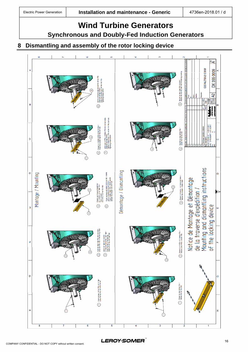
8 Dismantling and assembly of the rotor locking device
Electric Power Generation Installation and maintenance - Generic 4736en-2018.01 / d
Wind Turbine Generators Synchronous and Doubly-Fed Induction Generators
17
COMPANY CONFIDENTIAL - DO NOT COPY without written consent.
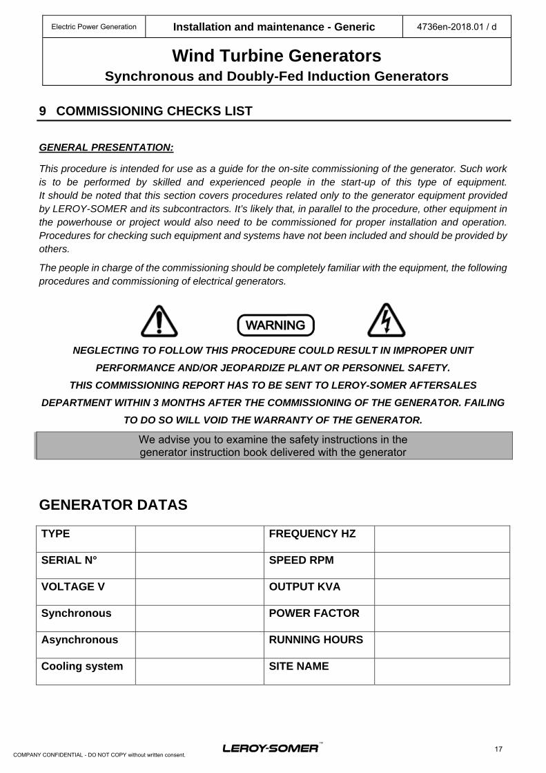
9 COMMISSIONING CHECKS LIST GENERAL PRESENTATION:
This procedure is intended for use as a guide for the on-site commissioning of the generator. Such work is to be performed by skilled and experienced people in the start-up of this type of equipment. It should be noted that this section covers procedures related only to the generator equipment provided by LEROY-SOMER and its subcontractors. It’s likely that, in parallel to the procedure, other equipment in the powerhouse or project would also need to be commissioned for proper installation and operation. Procedures for checking such equipment and systems have not been included and should be provided by others.
The people in charge of the commissioning should be completely familiar with the equipment, the following procedures and commissioning of electrical generators.
NEGLECTING TO FOLLOW THIS PROCEDURE COULD RESULT IN IMPROPER UNIT
PERFORMANCE AND/OR JEOPARDIZE PLANT OR PERSONNEL SAFETY.
THIS COMMISSIONING REPORT HAS TO BE SENT TO LEROY-SOMER AFTERSALES
DEPARTMENT WITHIN 3 MONTHS AFTER THE COMMISSIONING OF THE GENERATOR. FAILING
TO DO SO WILL VOID THE WARRANTY OF THE GENERATOR.
We advise you to examine the safety instructions in the generator instruction book delivered with the generator
GENERATOR DATAS
TYPE FREQUENCY HZ
SERIAL N° SPEED RPM
VOLTAGE V OUTPUT KVA
Synchronous POWER FACTOR
Asynchronous RUNNING HOURS
Cooling system SITE NAME
Electric Power Generation Installation and maintenance - Generic 4736en-2018.01 / d
Wind Turbine Generators Synchronous and Doubly-Fed Induction Generators
18
COMPANY CONFIDENTIAL - DO NOT COPY without written consent.
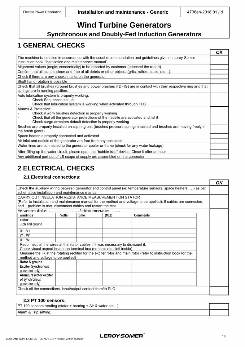
1 GENERAL CHECKS OKThe machine is installed in accordance with the usual recommendation and guidelines given in Leroy-Somer instruction book “installation and maintenance manual”
Alignment values (angle; concentricity) to be reported by customer (attached the report)Confirm that all plant is clean and free of all debris or other objects (grits, rafters, tools, etc…).Check if there are any shocks marks on the generatorShaft hand rotation is possible Check that all brushes (ground brushes and power brushes if DFIG) are in contact with their respective ring and that springs are in running position.
Auto lubrication system is properly working: - Check Sequences set up - Check that lubrication system is working when activated through PLC
Alarms & Protection: - Check if worn brushes detection is properly working - Check that all the generator protections of the nacelle are activated and list it - Check surge arrestors default detection is properly working
Brushes are properly installed on slip ring unit (brushes pressure springs inserted and brushes are moving freely in the brush gears)
Space heater is properly connected and activated Air inlet and outlets of the generator are free from any obstaclesWater lines are connected to the generator cooler or frame (check for any water leakage)
After filling-up the water circuit, please open the “bubble trap” device. Close it after an hourAny additional part out of LS scope of supply are assembled on the generator
2 ELECTRICAL CHECKS 2.1 Electrical connections:
OKCheck the auxiliary wiring between generator and control panel (ie: temperature sensors, space heaters, …) as per schematics installation and maintenance manual
CARRY OUT INSULATION RESISTANCE MEASUREMENT ON STATOR (Refer to installation and maintenance manual for the method and voltage to be applied). If cables are connected, and 1 problem is met, disconnect cables and restart the test.
Measurement device: …………………………..Ambient temperature:………… windings Volts time (MΩ) Comments stator 3 ph and ground
U1 ; V1 V1 ; W1 U1 ; W1 Reconnect all the wires at the stator cables if it was necessary to dismount it. Check visual aspect inside the terminal box (no tools etc.. left inside) Measure the IR at the rotating rectifier for the exciter rotor and main rotor (refer to instruction book for the method and voltage to be applied) Rotor & ground Exciter (synchronous generator only)
Armature (rotor exciter of synchronous generator only)
Check all the connections, input/output contact from/to PLC
2.2 PT 100 sensors: PT 100 sensors reading (stator + bearing + Air & water etc…)
Alarm & Trip setting.
Electric Power Generation Installation and maintenance - Generic 4736en-2018.01 / d
Wind Turbine Generators Synchronous and Doubly-Fed Induction Generators
19
COMPANY CONFIDENTIAL - DO NOT COPY without written consent.
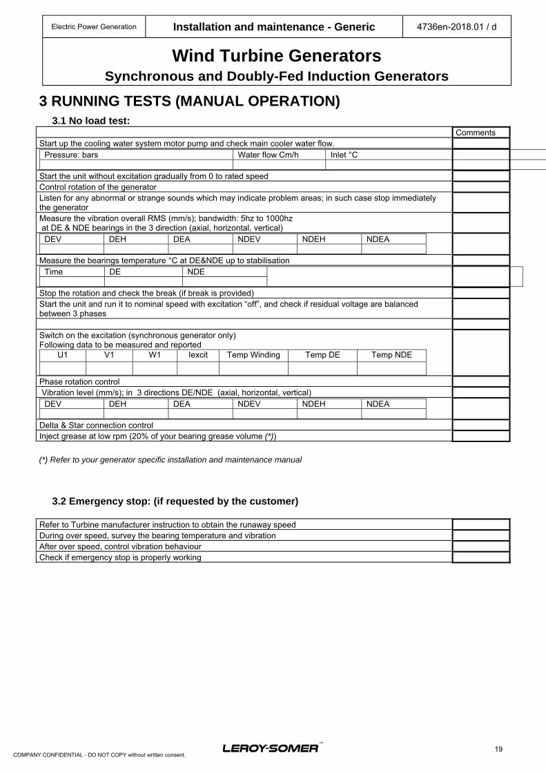
3 RUNNING TESTS (MANUAL OPERATION)
3.1 No load test: CommentsStart up the cooling water system motor pump and check main cooler water flow.
Pressure: bars Water flow Cm/h Inlet °C
Start the unit without excitation gradually from 0 to rated speed Control rotation of the generator Listen for any abnormal or strange sounds which may indicate problem areas; in such case stop immediately the generator
Measure the vibration overall RMS (mm/s); bandwidth: 5hz to 1000hz at DE & NDE bearings in the 3 direction (axial, horizontal, vertical)
DEV DEH DEA NDEV NDEH NDEA
Measure the bearings temperature °C at DE&NDE up to stabilisationTime DE NDE
Stop the rotation and check the break (if break is provided)Start the unit and run it to nominal speed with excitation “off”, and check if residual voltage are balanced between 3 phases
Switch on the excitation (synchronous generator only) Following data to be measured and reported
U1 V1 W1 Iexcit Temp Winding Temp DE Temp NDE
Phase rotation control Vibration level (mm/s); in 3 directions DE/NDE (axial, horizontal, vertical)
DEV DEH DEA NDEV NDEH NDEA
Delta & Star connection control Inject grease at low rpm (20% of your bearing grease volume (*))
(*) Refer to your generator specific installation and maintenance manual
3.2 Emergency stop: (if requested by the customer)
Refer to Turbine manufacturer instruction to obtain the runaway speedDuring over speed, survey the bearing temperature and vibrationAfter over speed, control vibration behaviour Check if emergency stop is properly working
Electric Power Generation Installation and maintenance - Generic 4736en-2018.01 / d
Wind Turbine Generators Synchronous and Doubly-Fed Induction Generators
20
COMPANY CONFIDENTIAL - DO NOT COPY without written consent.
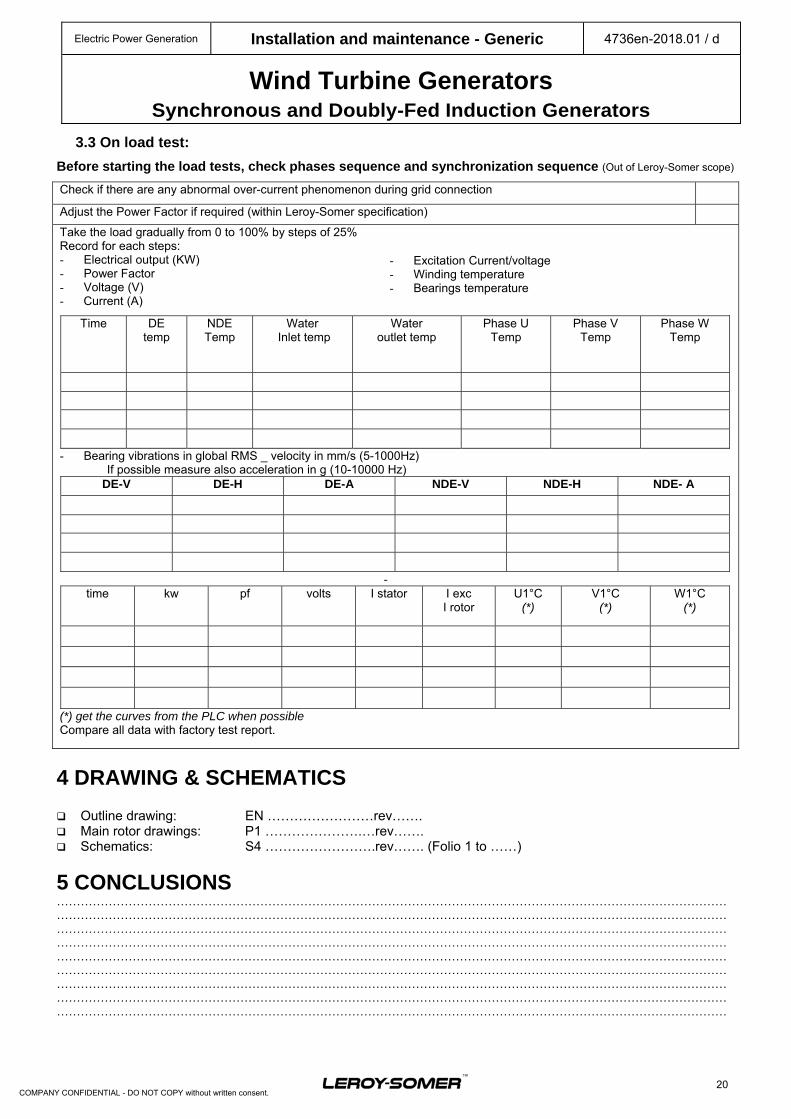
3.3 On load test:
Before starting the load tests, check phases sequence and synchronization sequence (Out of Leroy-Somer scope)
Check if there are any abnormal over-current phenomenon during grid connection
Adjust the Power Factor if required (within Leroy-Somer specification)
Take the load gradually from 0 to 100% by steps of 25% Record for each steps: - Electrical output (KW) - Power Factor - Voltage (V) - Current (A)
Time DE temp
NDE Temp
Water Inlet temp
Water outlet temp
Phase U Temp
Phase V Temp
Phase W Temp
- Bearing vibrations in global RMS _ velocity in mm/s (5-1000Hz) If possible measure also acceleration in g (10-10000 Hz)
DE-V DE-H DE-A NDE-V NDE-H NDE- A
- time kw pf volts I stator I exc
I rotor U1°C
(*) V1°C
(*) W1°C
(*)
(*) get the curves from the PLC when possible Compare all data with factory test report.
4 DRAWING & SCHEMATICS Outline drawing: EN ……………………rev……. Main rotor drawings: P1 ………………….…rev……. Schematics: S4 …………………….rev……. (Folio 1 to ……)
5 CONCLUSIONS …………………………………………………………………………………………………………………………………………………………………………………………………………………………………………………………………………………………………………………………………………………………………………………………………………………………………………………………………………………………………………………………………………………………………………………………………………………………………………………………………………………………………………………………………………………………………………………………………………………………………………………………………………………………………………………………………………………………………………………………………………………………………………………………………………………… …………………………………………………………………………………………………………………………………………………… ……………………………………………………………………………………………………………………………………………………
- Excitation Current/voltage - Winding temperature - Bearings temperature
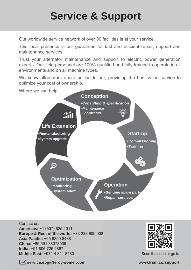
Our worldwide service network of over 80 facilities is at your service.
This local presence is our guarantee for fast and efficient repair, support and maintenance services.
Trust your alternator maintenance and support to electric power generation experts. Our field personnel are 100% qualified and fully trained to operate in all environments and on all machine types.
We know alternators operation inside out, providing the best value service to optimize your cost of ownership.
Where we can help: Conception •Consulting & specification
•Maintenance contracts
Life Extension
•Remanufacturing
•System upgrade
Start-up
•Commissioning
•Training
Optimization •Monitoring
•System audit
Operation
•Genuine spare parts
•Repair services
Contact us: Americas: +1 (507) 625 4011 Europe & Rest of the world: +33 238 609 908Asia Pacific: +65 6250 8488 China: +86 591 88373036 India: +91 806 726 4867 Middle East: +971 4 811 8483 Scan the code or go to:
[email protected] www.lrsm.co/support
Service & Support

Linkedin.com/company/Leroy-Somer
Twitter.com/Leroy_Somer_en
Facebook.com/LeroySomer.Nidec.en
YouTube.com/LeroySomerOfficiel
4736en-2018.01 / d
www.leroy-somer.com/epg