Embed Size (px)
Citation preview
WIND TURBINE GEARBOX TECHNOLOGIES © A. Ragheb and M. Ragheb
5/2/2019
INTRODUCTION
The reliability problems associated with transmission or gearbox equipped wind
turbines and the existing solutions of using direct drive gearless turbines and torque-
splitting are reviewed. As alternative solutions we propose the consideration of
Continuously Variable Transmissions (CVT) and Geared Turbofan Engine (GTF)
technology from the aerospace industry and discuss its promise in addressing the gearbox
problems currently encountered by existing wind turbine technology.
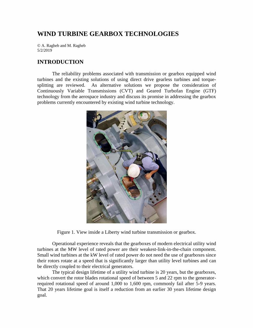
Figure 1. View inside a Liberty wind turbine transmission or gearbox.
Operational experience reveals that the gearboxes of modern electrical utility wind
turbines at the MW level of rated power are their weakest-link-in-the-chain component.
Small wind turbines at the kW level of rated power do not need the use of gearboxes since
their rotors rotate at a speed that is significantly larger than utility level turbines and can
be directly coupled to their electrical generators.
The typical design lifetime of a utility wind turbine is 20 years, but the gearboxes,
which convert the rotor blades rotational speed of between 5 and 22 rpm to the generator-
required rotational speed of around 1,000 to 1,600 rpm, commonly fail after 5-9 years.
That 20 years lifetime goal is itself a reduction from an earlier 30 years lifetime design
goal.
OPERATIONAL EXPERIENCE
Among insurers, who raced into the market in the 1990s, wind power is currently
considered a risky sector. German industry giant Allianz was faced with around 1,000
damage claims in the year 2006 alone. Gearboxes had to be replaced in large numbers
according to the German Insurance Association.
On average, an operator has to expect damage to his facility every four years,
excluding malfunctions and uninsured breakdowns.
Many insurance companies now are writing maintenance requirements requiring
wind producers to replace vulnerable components such as gearboxes every five years
directly into their contracts. A gearbox replacement can cost up to 10 percent of the
original construction cost, enough to cut deep into the projected profits.
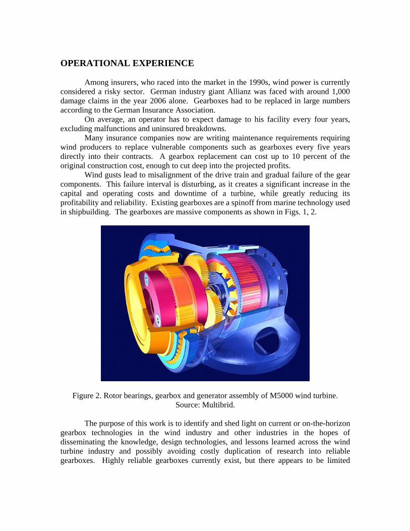
Wind gusts lead to misalignment of the drive train and gradual failure of the gear
components. This failure interval is disturbing, as it creates a significant increase in the
capital and operating costs and downtime of a turbine, while greatly reducing its
profitability and reliability. Existing gearboxes are a spinoff from marine technology used
in shipbuilding. The gearboxes are massive components as shown in Figs. 1, 2.
Figure 2. Rotor bearings, gearbox and generator assembly of M5000 wind turbine.
Source: Multibrid.
The purpose of this work is to identify and shed light on current or on-the-horizon
gearbox technologies in the wind industry and other industries in the hopes of
disseminating the knowledge, design technologies, and lessons learned across the wind
turbine industry and possibly avoiding costly duplication of research into reliable
gearboxes. Highly reliable gearboxes currently exist, but there appears to be limited
exchange of information between the aerospace propulsion industry and the wind turbine
industry.
This work will review the current solutions to the gearbox problem through the
direct drive approach, provide a background on turbofans from the aerospace industry and
their technologies as a possible solution, and examine the benefits and disadvantages of
using a Continuously Variable Transmission (CVT).
GEARLESS OR DIRECT DRIVE WIND TURBINES
Currently, Enercon GmbH of Aurich, Germany has presented a mass-produced
solution to the low gearbox reliability. It has licensed the technology to Japan Steel Works,
JSW in Japan.
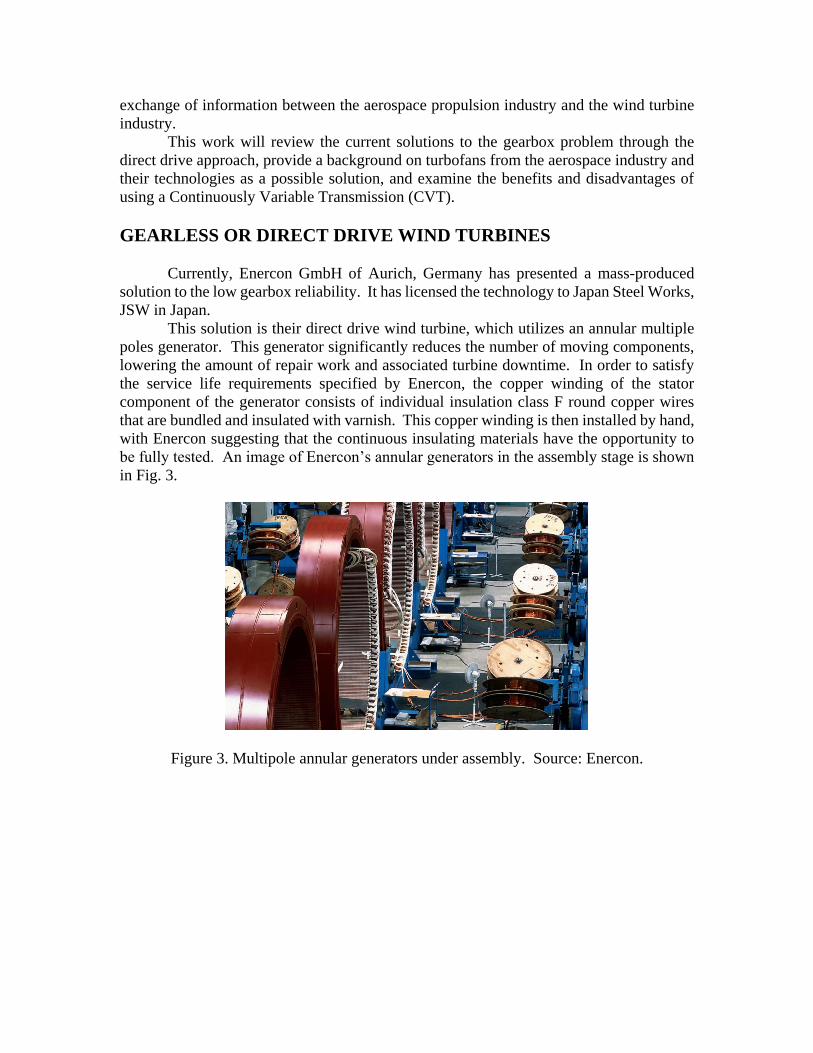
This solution is their direct drive wind turbine, which utilizes an annular multiple
poles generator. This generator significantly reduces the number of moving components,
lowering the amount of repair work and associated turbine downtime. In order to satisfy
the service life requirements specified by Enercon, the copper winding of the stator
component of the generator consists of individual insulation class F round copper wires
that are bundled and insulated with varnish. This copper winding is then installed by hand,
with Enercon suggesting that the continuous insulating materials have the opportunity to
be fully tested. An image of Enercon’s annular generators in the assembly stage is shown
in Fig. 3.
Figure 3. Multipole annular generators under assembly. Source: Enercon.
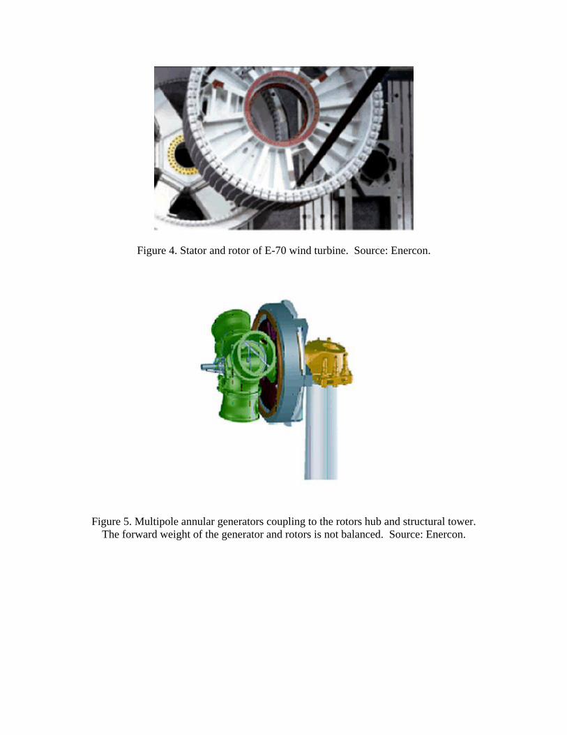
Figure 4. Stator and rotor of E-70 wind turbine. Source: Enercon.
Figure 5. Multipole annular generators coupling to the rotors hub and structural tower.
The forward weight of the generator and rotors is not balanced. Source: Enercon.
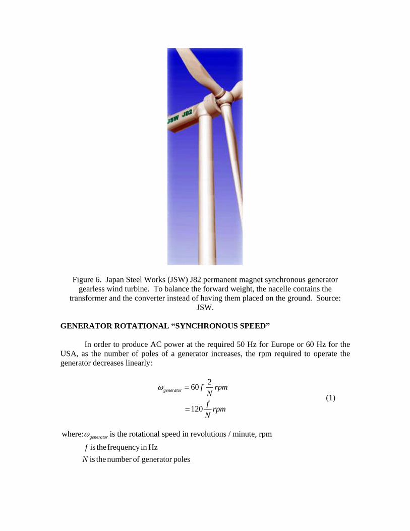
Figure 6. Japan Steel Works (JSW) J82 permanent magnet synchronous generator
gearless wind turbine. To balance the forward weight, the nacelle contains the
transformer and the converter instead of having them placed on the ground. Source:
JSW.
GENERATOR ROTATIONAL “SYNCHRONOUS SPEED”
In order to produce AC power at the required 50 Hz for Europe or 60 Hz for the
USA, as the number of poles of a generator increases, the rpm required to operate the
generator decreases linearly:
260
120
generator f rpmN
frpm
N
(1)
where: is the rotational speed in revolutions / minute, rpm
is thefrequency in Hz
is the number of generator poles
generator
f
N
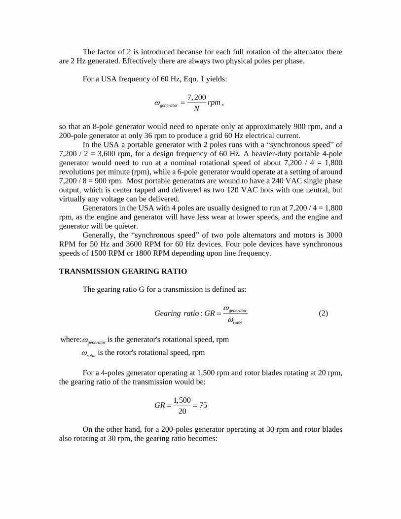
The factor of 2 is introduced because for each full rotation of the alternator there
are 2 Hz generated. Effectively there are always two physical poles per phase.
For a USA frequency of 60 Hz, Eqn. 1 yields:
7,200
generator rpmN
,
so that an 8-pole generator would need to operate only at approximately 900 rpm, and a
200-pole generator at only 36 rpm to produce a grid 60 Hz electrical current.
In the USA a portable generator with 2 poles runs with a “synchronous speed” of
7,200 / 2 = 3,600 rpm, for a design frequency of 60 Hz. A heavier-duty portable 4-pole
generator would need to run at a nominal rotational speed of about 7,200 / 4 = 1,800
revolutions per minute (rpm), while a 6-pole generator would operate at a setting of around
7,200 / 8 = 900 rpm. Most portable generators are wound to have a 240 VAC single phase
output, which is center tapped and delivered as two 120 VAC hots with one neutral, but
virtually any voltage can be delivered.
Generators in the USA with 4 poles are usually designed to run at 7,200 / 4 = 1,800
rpm, as the engine and generator will have less wear at lower speeds, and the engine and
generator will be quieter.
Generally, the “synchronous speed” of two pole alternators and motors is 3000
RPM for 50 Hz and 3600 RPM for 60 Hz devices. Four pole devices have synchronous
speeds of 1500 RPM or 1800 RPM depending upon line frequency.
TRANSMISSION GEARING RATIO
The gearing ratio G for a transmission is defined as:
:generator
rotor
Gearing ratio GR
(2)
where: is the generator's rotational speed, rpm
is the rotor's rotational speed, rpm
generator
rotor
For a 4-poles generator operating at 1,500 rpm and rotor blades rotating at 20 rpm,
the gearing ratio of the transmission would be:
1,500
7520
GR
On the other hand, for a 200-poles generator operating at 30 rpm and rotor blades
also rotating at 30 rpm, the gearing ratio becomes:
30
130
GR
thus requiring no gearbox component.
ANNULAR GENERATOR
The annular generator is of primary importance in the gearless system design of the
E-70 wind turbine. It offers the advantages of totally avoiding the gearbox components, a
lower wear caused by a slow machine rotation, low stress due to the high level of speed
variability, the incorporation of yield optimized control and the high level of grid
compatibility.
Combined with the rotor hub, it provides an almost frictionless flow of energy,
while the gentle running of fewer moving components guarantees minimal material wear.
Unlike conventional asynchronous generators, the annular generator is subjected to
minimal mechanical wear, which makes it ideal for particularly heavy demands and a long
service life.
The annular generator is a low speed synchronous generator with no direct grid
coupling. The output voltage and frequency vary with the speed and are converted for
output to the grid by a DC link and inverter. This achieves a high degree of speed
variability.
STATOR AND ROTOR
The copper winding in the stator, the stationary part of the annular generator, uses
a single layer basket winding that is produced using the insulation class F to 155 °C. It
consists of individual round wires that are gathered in bundles and insulated with varnish.
The copper winding is done manually. In spite of increasing automation in other
manufacturing areas, preference has been given to manual labor in this case since it ensures
that the materials used are fully tested. A special processing method allows continuous
windings to be produced. Each wire strand is continuous from start to finish.
The advantages of continuous winding are:
1. Prevents processing faults in the production of electrical connections.
2. Maintains the high quality copper wire insulating system.
3. Eliminates the contact resistance.
4. Eliminates weak points that are susceptible to corrosion or material fatigue.
The magnetic field of the stator winding is excited by pole shoes. These are located
on the disk rotor, the mobile part of the annular generator. Since the shape and position of
the pole shoes have a decisive influence on the noise emission of the annular generator,
Research and Development (RD) has dedicated particular attention to this aspect. The
result is an improved adaptation of the pole shoes to the slow rotation of the annular
generator with no significant noise being generated.
GEARBOX DESIGN OPTIONS
The weakest link of a wind turbine has been its gearbox. As turbine sizes increased,
the design gearboxes able to handle the torque generated by longer and heavier blades has
become a major problem. In addition, turbine loading is variable and hard to predict. Some
gearboxes have failed in less than two years of operation.
Most of these failures have been attributed to the movement of the machine chassis,
which causes misalignment of the gearbox with the generator shafts and leads to failure.
Such failure occurs in the high speed rear gearing portion of the gearbox when the bearings
become faulty.
The frequency of failures can be reduced by regular turbine realignments.
Manufacturers have made their turbines more reliable by improving the oil
lubrication and filtration system in the gearbox so it can remove all particles larger than
seven microns in size. If a particle of that size breaks free of the meshing gears, it can
damage other gears and bearings.
Manufacturers in Germany and under license in Japan have increased the number
of generator poles in their machines, eliminating the gearbox. Most electrical generators
have 4 or 6 magnetic pole pairs in their windings and must use a gearbox. With the
generator built with 50-100 pole pairs, the use of electronic control can eliminate the need
for a gearbox.
The coupling of the blades directly to the generator in machines without a gearbox
also eliminates the mechanical or tonal noise produced by conventional turbines.
TORQUE SPLITTING, DISTRIBUTED GEARING
A California based wind turbine manufacturer in the USA, improved reliability by
using distributed gearing using multiple paths and 4 generators to ensure continued turbine
operation even if one of the generators fails.
It encountered a problem with its 2.5 MW turbine design, which experienced
quality control and an apparent design problem, affecting the company’s financial
performance.
The 20 MW Steel Winds wind farm in upstate New York, using eight of the
turbines, has been shut down because of a gearbox problem in the turbines. All eight
turbines suffered from a manufacturing problem and repairing the problem required several
months.
The Steel Winds project, on a former Bethlehem Steel site that is also a listed
Superfund toxic waste site, was the first to use the 2.5 MW machines. The eight wind
turbines rolled off the company’s assembly line in Cedar Rapids, Iowa, in late 2006, and
went into service at the site on Lake Erie in April 2007.
The operators of the project, UPC Wind and BQ Energy, first noticed the problems
with the wind machines in August 2007. Upon inspection, engineers discovered that a
tooth on one of the four gears in the box had broken. Inspections found the problem on all
of the turbines on the site.
Similar turbines at projects in Iowa and Minnesota had the same problem and
required repairs. SNL Financial, a trade news service, reported that 50 turbines required
repair. The Steel Wind turbines were all under warranty, according to a UPC Wind official,
so the manufacturer covered the costs of repair.
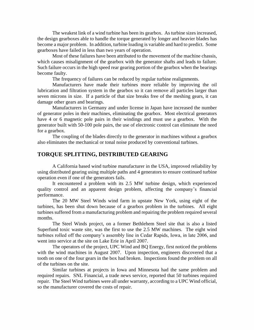
The turbines use a unique approach in their gearboxes to cope with the large torque
generated by the turbine blades; that are longer than the wing of a Boeing 747 airplane, on
the gear box. The drive train of the wind turbine uses torque splitting and feed it into four
turbo generators operating in parallel. An advantage is that the turbine can continue
operation with one generator out of service and awaiting repair.
Figure 7. Torque splitting between four electrical generators operated in parallel. The
turbine can continue operation with one generator out of service. Source: Clipper Wind
Power Inc.
MANUAL LABOR VERSUS AUTOMATION
The general trend in the manufacturing industry is to move away from manual labor
and automate as much production as possible or outsource it. Outsourcing solves the
problems associated with increasing labor costs and lengthy work stoppages, both of which
may at least in part be attributed to unions. The Boeing Company of Chicago, Illinois was
dealt a significant blow by an eight-week machinist strike at the end of 2008, which delayed
the deliveries of around 50 aircraft, further delayed the already-late 787 test program, and
caused further damage to the reputation of the company.
It should be noted that outsourcing has two inherent problems: by outsourcing,
proprietary technologies and/or processes are transferred to the receiving country, and it is
only a temporary solution. As the wealth of the outsourcee country grows, its workers will
demand ever-increasing wages and benefits. In addition to this, money is exiting the
outsourcing country to the outsourcee, and through the aforementioned technology
transfer, outsourcing may inadvertently be creating a new competitor through the
technology transfers.
Technology transfer is a significant disadvantage to outsourcing of manual labor,
which is becoming ever-increasingly unaffordable in industrialized First World nations.
For these reasons, it can be inferred that hand-built electrical generators for wind turbines
are not viable in the far-term.
WIND TURBINE INDUSTRY STRATEGIES
In July 2008, Siemens Energy embarked upon a 2-year testing program for a 3.6
MW experimental direct drive turbine. This concept machine was installed near the coast
of Ringkøbing, Denmark, with a second slightly-different generator design to be installed
by December 2008. Henrik Stiesdal commented that Siemens realizes that direct drive
wind turbines may become competitive with their geared counterparts at the upper end of
turbine sizes, and through these two test rigs hopes to determine if and at what level direct
drive systems can be made competitive.
HISTORY OF DIRECT DRIVE
During the past few years, the market share for direct drive wind turbines accounted
for 13-15 percent of the total turbine market, with the number standing at 14 percent in
2007. Enercon of Germany has dominated the direct drive wind turbine market since they
introduced their first direct drive system in 1993, with their current product range offering
turbines of power 100 kW to 6 MW and about 12,600 systems produced by 2009.
Enercon’s flagship model is the E-126, which features a 12 meter diameter annular
generator and a 127 meter blade diameter.
Japan Steel Works (JSW) became involved in Wind Power Systems using its long
experience in industrial machinery and energy technology. Initially, it delivered 30 sets of
General Electric (GE) 1.5s wind turbines in Japan. Using the acquired operational
experience, JSW adopted the technology of permanent magnet gearless synchronous
generator wind turbines from Enercon in Germany and manufactures its own wind turbine
including the rotor blades and the tower.
Enercon has been effective in meeting its competition, as companies such as
Jeumont Industrie, Seewind, and Heidelberg have all offered direct drive turbine concepts,
but have yet to result in any sort of commercial impact.
Lagerwey of the Netherlands offered a 750 kW family of turbines, but filed for
bankruptcy in 2003 after fabricating only 200 units. Emergya Wind Technology purchased
the Lagerwey technology and since 2004 has offered a 900 kW DirectWing 900*54 wind
turbine, effectively having scaled up the Lagerway technology. The former leaders of
Lagerwey produced one 2 MW direct drive prototype under the auspices of the Zephyros
consortium, but sold it to Harokasan in Japan.
Despite the prior failings of competitors to Enercon in the direct drive market
sector, there exists a high level of optimism and a growing level of interest. In addition to
the efforts of Siemens Energy, a number of companies are currently attempting to gain a
foothold in the direct drive sector, and they are summarized below in Table 1.
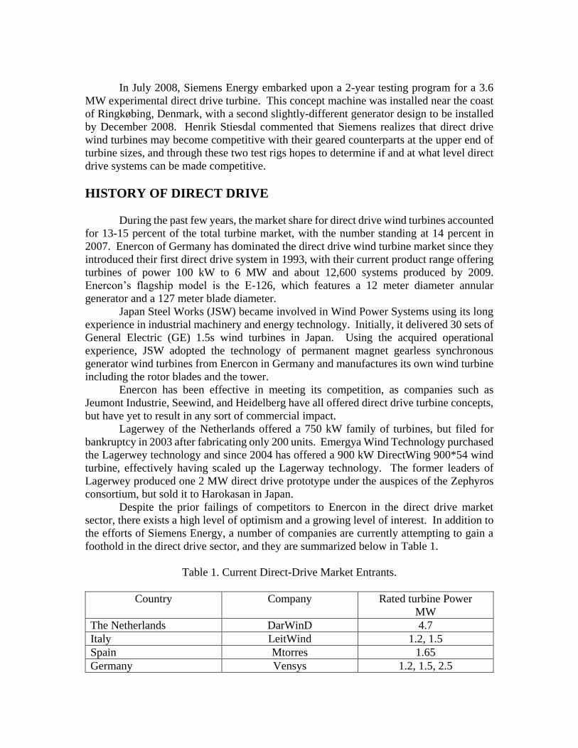
Table 1. Current Direct-Drive Market Entrants.
Country Company Rated turbine Power
MW
The Netherlands DarWinD 4.7
Italy LeitWind 1.2, 1.5
Spain Mtorres 1.65
Germany Vensys 1.2, 1.5, 2.5
Norway ScanWind 3.5
South Korea Unison 0.75
It should be noted that interest from coal-rich China indeed does exist, as Goldwind
currently licenses production of Vensys wind turbines, and as of recently, owns 70 percent
of the Vensys shares.
Currently, the direct drive generator design of choice is the Permanent Magnet
(PM) type of generator. Benefits of PM generators include their compactness relative to
external field excitation generators as well as the fact that it is widely held that this
generator design exhibits a very high efficiency even when subjected to a partial load.
Disadvantages of PM generators however include the inability to control the field strength
and significantly more stringent manufacturing and tolerance requirements.
GEARED TURBOFAN, GTF TECHNOLOGY
Pratt and Whitney, the maker of jet engines powering aircraft such as the F-15 Eagle
, 747 Jumbo Jet, and C-17 Globemaster, spent over 10 years of research and over $350
million in development costs to develop a Geared Turbo Fan Engine (GTF). In order to
understand why this jet engine technology development has potential positive implications
for the wind turbine industry, one must first understand how and within what environment
a turbofan engine operates.
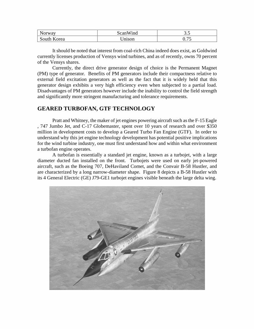
A turbofan is essentially a standard jet engine, known as a turbojet, with a large
diameter ducted fan installed on the front. Turbojets were used on early jet-powered
aircraft, such as the Boeing 707, DeHaviland Comet, and the Convair B-58 Hustler, and
are characterized by a long narrow-diameter shape. Figure 8 depicts a B-58 Hustler with
its 4 General Electric (GE) J79-GE1 turbojet engines visible beneath the large delta wing.
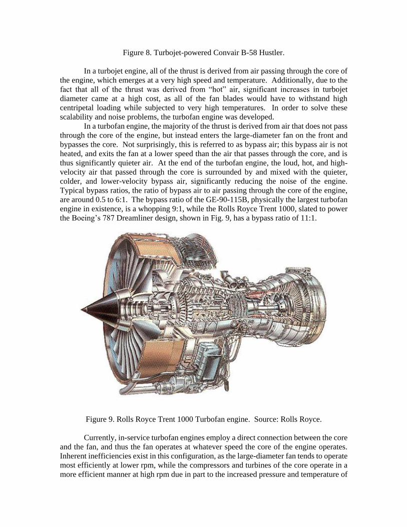
Figure 8. Turbojet-powered Convair B-58 Hustler.
In a turbojet engine, all of the thrust is derived from air passing through the core of
the engine, which emerges at a very high speed and temperature. Additionally, due to the
fact that all of the thrust was derived from “hot” air, significant increases in turbojet
diameter came at a high cost, as all of the fan blades would have to withstand high
centripetal loading while subjected to very high temperatures. In order to solve these
scalability and noise problems, the turbofan engine was developed.
In a turbofan engine, the majority of the thrust is derived from air that does not pass
through the core of the engine, but instead enters the large-diameter fan on the front and
bypasses the core. Not surprisingly, this is referred to as bypass air; this bypass air is not
heated, and exits the fan at a lower speed than the air that passes through the core, and is
thus significantly quieter air. At the end of the turbofan engine, the loud, hot, and high-
velocity air that passed through the core is surrounded by and mixed with the quieter,
colder, and lower-velocity bypass air, significantly reducing the noise of the engine.
Typical bypass ratios, the ratio of bypass air to air passing through the core of the engine,
are around 0.5 to 6:1. The bypass ratio of the GE-90-115B, physically the largest turbofan
engine in existence, is a whopping 9:1, while the Rolls Royce Trent 1000, slated to power
the Boeing’s 787 Dreamliner design, shown in Fig. 9, has a bypass ratio of 11:1.
Figure 9. Rolls Royce Trent 1000 Turbofan engine. Source: Rolls Royce.
Currently, in-service turbofan engines employ a direct connection between the core
and the fan, and thus the fan operates at whatever speed the core of the engine operates.
Inherent inefficiencies exist in this configuration, as the large-diameter fan tends to operate
most efficiently at lower rpm, while the compressors and turbines of the core operate in a
more efficient manner at high rpm due in part to the increased pressure and temperature of
the core, and the fact that smaller-diameter fans can operate at higher rpm before the tip
speeds reach supersonic speeds. Once tip speeds reach a supersonic speed, shockwaves
and other instabilities significantly reduce the aerodynamic efficiency of the blades, and
introduce unwanted stresses.
Pratt and Whitney’s insertion of a gearbox between the core and the fan of a jet
engine allows independent adjustment of the fan and core rpm, and is projected to offer an
efficiency increase of approximately 9 percent.
GEARED TURBOFAN, GTF DEVELOPMENT
The geared turbofan engine is not a new concept, as Pratt and Whitney understood
the theoretical justification behind the concept by the early 1980s. The reason for this
concept only now, nearly 30 years later, appearing on actual jet engines is the level of
technology and materials development required to satisfy the stringent safety, reliability,
and ruggedness requirements of modern jet turbines. Pratt and Whitney suggests that
through thousands of hours of development, advances in bearing, gear system, and
lubrication design have been made and incorporated into their new family of GTFs.
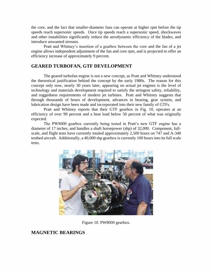
Pratt and Whitney reports that their GTF gearbox in Fig. 10, operates at an
efficiency of over 99 percent and a heat load below 50 percent of what was originally
expected.
The PW8000 gearbox currently being tested in Pratt’s new GTF engine has a
diameter of 17 inches, and handles a shaft horsepower (shp) of 32,000. Component, full-
scale, and flight tests have currently totaled approximately 2,500 hours on 747 and A-340
testbed aircraft. Additionally, a 40,000 shp gearbox is currently 100 hours into its full scale
tests.
Figure 10. PW8000 gearbox.
MAGNETIC BEARINGS
Pratt and Whitney goes on to claim the existence of a proprietary “self-centering”
technology to nearly eliminate all instances of stress and gear misalignment, problems
discussed by Ragheb [1] on wind turbine gearboxes that cause severe reliability problems.
We surmise that magnetic levitation with permanent or electromagnets is used in lieu of
ball bearings to self-align the transmission shafts (Figs. 11, 12).
Magnetic bearings offer a host of advantages, including high speed capabilities and
the ability to operate lubrication-free and in vacuum environments. They generate no
friction, experience minimal wear, and operate contamination free with extremely low
vibration.
Magnetic bearings can precisely control shaft position, measure external forces
acting on the shaft, and monitor a machine's operating condition. Magnetic-bearing
systems electromagnetically suspend shafts by applying electric current to a bearing's
ferromagnetic materials. The systems have three main elements: bearing actuators, position
sensors, and controller and control algorithms.
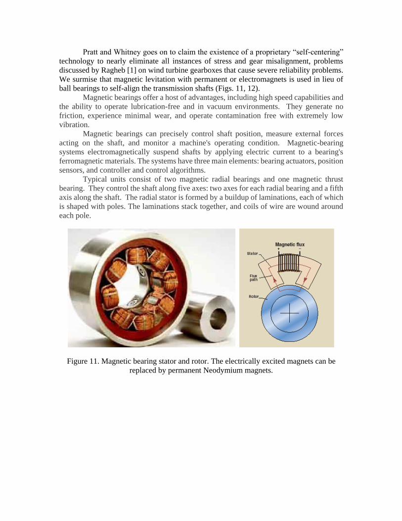
Typical units consist of two magnetic radial bearings and one magnetic thrust
bearing. They control the shaft along five axes: two axes for each radial bearing and a fifth
axis along the shaft. The radial stator is formed by a buildup of laminations, each of which
is shaped with poles. The laminations stack together, and coils of wire are wound around
each pole.
Figure 11. Magnetic bearing stator and rotor. The electrically excited magnets can be
replaced by permanent Neodymium magnets.
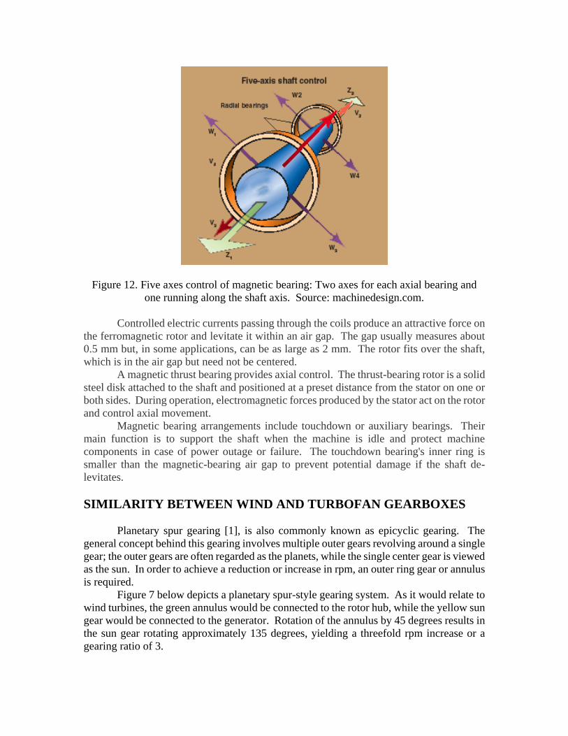
Figure 12. Five axes control of magnetic bearing: Two axes for each axial bearing and
one running along the shaft axis. Source: machinedesign.com.
Controlled electric currents passing through the coils produce an attractive force on
the ferromagnetic rotor and levitate it within an air gap. The gap usually measures about
0.5 mm but, in some applications, can be as large as 2 mm. The rotor fits over the shaft,
which is in the air gap but need not be centered.
A magnetic thrust bearing provides axial control. The thrust-bearing rotor is a solid
steel disk attached to the shaft and positioned at a preset distance from the stator on one or
both sides. During operation, electromagnetic forces produced by the stator act on the rotor
and control axial movement.
Magnetic bearing arrangements include touchdown or auxiliary bearings. Their
main function is to support the shaft when the machine is idle and protect machine
components in case of power outage or failure. The touchdown bearing's inner ring is
smaller than the magnetic-bearing air gap to prevent potential damage if the shaft de-
levitates.
SIMILARITY BETWEEN WIND AND TURBOFAN GEARBOXES
Planetary spur gearing [1], is also commonly known as epicyclic gearing. The
general concept behind this gearing involves multiple outer gears revolving around a single
gear; the outer gears are often regarded as the planets, while the single center gear is viewed
as the sun. In order to achieve a reduction or increase in rpm, an outer ring gear or annulus
is required.
Figure 7 below depicts a planetary spur-style gearing system. As it would relate to
wind turbines, the green annulus would be connected to the rotor hub, while the yellow sun
gear would be connected to the generator. Rotation of the annulus by 45 degrees results in
the sun gear rotating approximately 135 degrees, yielding a threefold rpm increase or a
gearing ratio of 3.
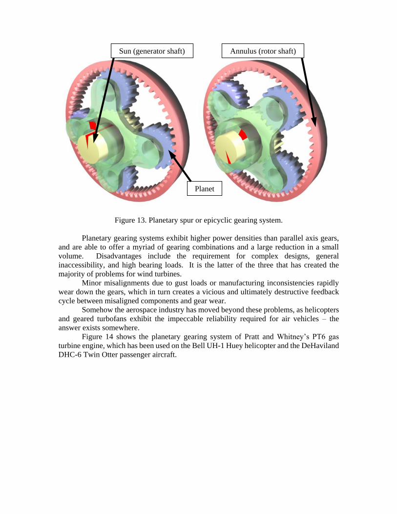
Figure 13. Planetary spur or epicyclic gearing system.
Planetary gearing systems exhibit higher power densities than parallel axis gears,
and are able to offer a myriad of gearing combinations and a large reduction in a small
volume. Disadvantages include the requirement for complex designs, general
inaccessibility, and high bearing loads. It is the latter of the three that has created the
majority of problems for wind turbines.
Minor misalignments due to gust loads or manufacturing inconsistencies rapidly
wear down the gears, which in turn creates a vicious and ultimately destructive feedback
cycle between misaligned components and gear wear.
Somehow the aerospace industry has moved beyond these problems, as helicopters
and geared turbofans exhibit the impeccable reliability required for air vehicles – the
answer exists somewhere.
Figure 14 shows the planetary gearing system of Pratt and Whitney’s PT6 gas
turbine engine, which has been used on the Bell UH-1 Huey helicopter and the DeHaviland
DHC-6 Twin Otter passenger aircraft.
Sun (generator shaft) Annulus (rotor shaft)
Planet
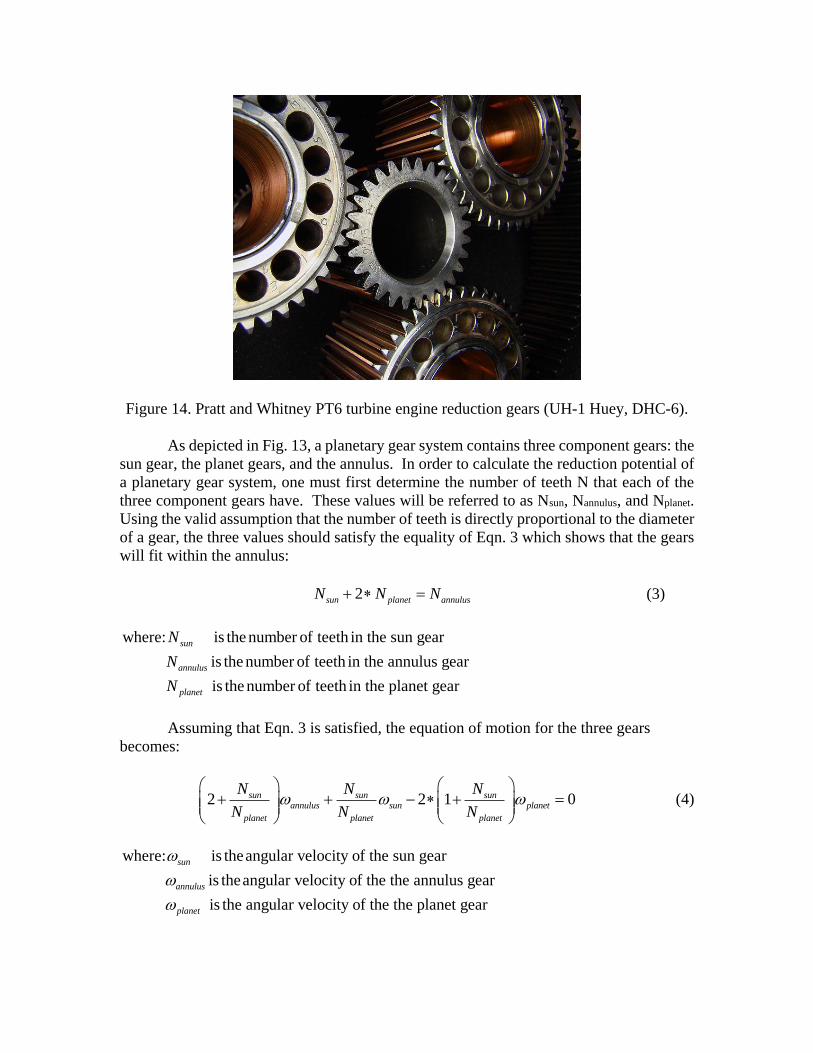
Figure 14. Pratt and Whitney PT6 turbine engine reduction gears (UH-1 Huey, DHC-6).
As depicted in Fig. 13, a planetary gear system contains three component gears: the
sun gear, the planet gears, and the annulus. In order to calculate the reduction potential of
a planetary gear system, one must first determine the number of teeth N that each of the
three component gears have. These values will be referred to as Nsun, Nannulus, and Nplanet.
Using the valid assumption that the number of teeth is directly proportional to the diameter
of a gear, the three values should satisfy the equality of Eqn. 3 which shows that the gears
will fit within the annulus:
2sun planet annulusN N N (3)
where: is the number of teeth in the sun gear
is the number of teeth in the annulus gear
is the number of teeth in the planet gear
sun
annulus
planet
N
N
N
Assuming that Eqn. 3 is satisfied, the equation of motion for the three gears
becomes:
2 2 1 0sun sun sunannulus sun planet
planet planet planet
N N N
N N N
(4)
where: is theangular velocity of the sun gear
is theangular velocity of the the annulus gear
is the angular velocity of the the planet gear
sun
annulus
planet
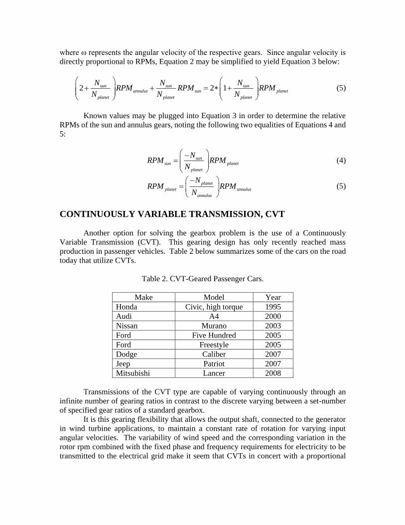
where ω represents the angular velocity of the respective gears. Since angular velocity is
directly proportional to RPMs, Equation 2 may be simplified to yield Equation 3 below:
2 2 1sun sun sunannulus sun planet
planet planet planet
N N NRPM RPM RPM
N N N
(5)
Known values may be plugged into Equation 3 in order to determine the relative
RPMs of the sun and annulus gears, noting the following two equalities of Equations 4 and
5:
sunsun planet
planet
NRPM RPM
N
(4)
planet
planet annulus
annulus
NRPM RPM
N
(5)
CONTINUOUSLY VARIABLE TRANSMISSION, CVT
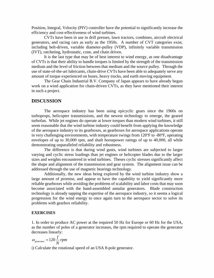
Another option for solving the gearbox problem is the use of a Continuously
Variable Transmission (CVT). This gearing design has only recently reached mass
production in passenger vehicles. Table 2 below summarizes some of the cars on the road
today that utilize CVTs.
Table 2. CVT-Geared Passenger Cars.
Make Model Year
Honda Civic, high torque 1995
Audi A4 2000
Nissan Murano 2003
Ford Five Hundred 2005
Ford Freestyle 2005
Dodge Caliber 2007
Jeep Patriot 2007
Mitsubishi Lancer 2008
Transmissions of the CVT type are capable of varying continuously through an
infinite number of gearing ratios in contrast to the discrete varying between a set-number
of specified gear ratios of a standard gearbox.
It is this gearing flexibility that allows the output shaft, connected to the generator
in wind turbine applications, to maintain a constant rate of rotation for varying input
angular velocities. The variability of wind speed and the corresponding variation in the
rotor rpm combined with the fixed phase and frequency requirements for electricity to be
transmitted to the electrical grid make it seem that CVTs in concert with a proportional
Position, Integral, Velocity (PIV) controller have the potential to significantly increase the
efficiency and cost-effectiveness of wind turbines.
CVTs have been in use in drill presses, lawn tractors, combines, aircraft electrical
generators, and racing cars as early as the 1950s. A number of CVT categories exist,
including belt-driven, variable diameter-pulley (VDP), infinitely variable transmission
(IVT), ratcheting, hydrostatic, cone, and chain driven.
It is the last type that may be of best interest to wind energy, as one disadvantage
of CVTs is that their ability to handle torques is limited by the strength of the transmission
medium and the level of friction between that medium and the source pulley. Through the
use of state-of-the-art lubricants, chain-drive CVTs have been able to adequately serve any
amount of torque experienced on buses, heavy trucks, and earth moving equipment.
The Gear Chain Industrial B.V. Company of Japan appears to have already begun
work on a wind application for chain-driven CVTs, as they have mentioned their interest
in such a project.
DISCUSSION
The aerospace industry has been using epicyclic gears since the 1960s on
turboprops, helicopter transmissions, and the newest technology to emerge, the geared
turbofan. While jet engines do operate at lower torques than modern wind turbines, it still
seem reasonable that the wind turbine industry could benefit from applying the knowledge
of the aerospace industry to its gearboxes, as gearboxes for aerospace applications operate
in very challenging environments, with temperature swings from 120ºF to -80ºF, operating
envelopes of up to 30,000 rpm, and shaft horsepower ratings of up to 40,000, all while
demonstrating unparalleled reliability and robustness.
The difference is that during wind gusts, wind turbines are subjected to larger
varying and cyclic stress loadings than jet engines or helicopter blades due to the larger
sizes and weights encountered in wind turbines. Theses cyclic stresses significantly affect
the shape and alignment of the transmission and gear system. The alignment issue can be
addressed through the use of magnetic bearings technology.
Additionally, the new ideas being explored by the wind turbine industry show a
large amount of promise, and appear to have the capability to yield significantly more
reliable gearboxes while avoiding the problems of scalability and labor costs that may soon
become associated with the hand-assembled annular generators. Blade construction
technology is already tapping the expertise of the aerospace industry, so it seems a logical
progression for the wind energy to once again turn to the aerospace sector to solve its
problems with gearbox reliability.
EXERCISES
1. In order to produce AC power at the required 50 Hz for Europe or 60 Hz for the USA,
as the number of poles of a generator increases, the rpm required to operate the generator
decreases linearly:
120generator
frpm
N
i) Calculate the rotational speed of an USA 8-pole generator.
ii) Calculate the rotational speed of an USA 200 pole generator.
iii) Calculate the rotational speed of an EU 8-pole generator.
iv) Calculate the rotational speed of an US 200 pole generator.
2. For a 4-poles generator operating at 1,500 rpm and rotor blades rotating at 20 rpm,
calculate the gearing ratio of a wind turbine transmission.
On the other hand, for a 200-poles wind turbine generator operating at 30 rpm and rotor
blades also rotating at 30 rpm, calculate the gearing ratio.
Discuss the implication of these results.
REFERENCES
1. M. Ragheb, “Wind Power Systems. Harvesting the Wind.”
https://mragheb.com/NPRE%20475%20Wind%20Power%20Systems/index.htm, 2019.
2. Thomas Ackerman, Ed. “Wind Power in Power Systems,” John Wiley and Sons, Ltd.,
2005.
3. American Institute of Aeronautics and Astronautics (AIAA) and American Society of
Mechanical Engineers (ASME), “A Collection of the 2004 ASME Wind Energy
Symposium Technical Papers,” 42nd AIAA Aerospace Sciences Meeting and Exhibit, Reno
Nevada, %-8 January, 2004.
4. Désiré Le Gouriérès, “Wind Power Plants, Theory and Design,” Pergamon Press, 1982.
5. Joseph E. Brown and Anne Ensign Brown, “Harness the Wind, The Story of Windmills,”
Dodd, Mead and Company, New York, 1977.
6. Frank R. Eldridge, “Wind machines,” 2nd Ed., The MITRE Energy Resources and
Environmental Series, Van Nostrand Reinhold Company, 1980
7. N. G. Calvert, “Windpower Principles: Their Application on the Small Scale,” John
Wiley and Sons, 1979.
8. Volta Torrey, “Wind-Catchers, American Windmills of Yesterday and Tomorrow,” The
Stephen Greene Press, Brattleboro, Vermont, 1976.
9. John F. Walker, and Nicholas Jenkins, “Wind Energy technology,” John Wiley and Sons,
1997.
10. J. Schmid and W. Palz, “European Wind Energy Technology, State of the Art Wind
Energy Converters in the European Community,” D. Reidel Publishing Company, 1986.
11. Energy Research and Development Administration (ERDA), Division of Solar Energy,
“Solar Program Assessment: Environmental Factors, Wind Energy Conversion,” ERDA
77-47/6, UC-11, 59, 62, 63A, March 1977.
12. http://www.flug-revue.rotor.com/FRHeft/FRH9810/FR9810h.htm.
13. http://en.wikipedia.org/wiki/Epicyclic_gearing#Advantages_.2F_Disadvantages
14. http://en.wikipedia.org/wiki/Turbofan#High-bypass_turbofan_engines
15. http://www.sae.org/aeromag/techinnovations/1298t10.htm
16. http://en.wikipedia.org/wiki/Continuously_variable_transmission
17.http://www.airbus.com/en/presscentre/pressreleases/pressreleases_items/08_10_14_ge
ared_turbofan_concept.html
18. http://www.wpdelfzijlzuid.nl/enercon.pdf
19. http://www.renewableenergyworld.com/rea/magazine/story?id=53850
20. http://www.multibrid.com/index.php?id=23&L=1

21.http://www.alliedfsgroup.com/?RhZbkYiCnAlN5wUqbekXqChlg3w2Ukhfhdl7nlfCI6
VjbfkaqAl
22. http://www.aerospace-technology.com/projects/arj21/
23. http://www.flightglobal.com/articles/2007/08/24/216287/building-a-future-the-avic-i-
arj21-700-programme.html