Embed Size (px)
Citation preview
2
3
4
1
5
6
7
8
7
8
6
5
4
3
2
1
B
A
C
D
B
A
C
D
POWER SYSTEMS INTEGRATION LAB
PROJECT:
DRAFTER:
DATE:
VERSION:
350mcm
250mcm
2x 500mcm
350mcm
2/0 AWG
4/0 AWG
SWITCH BOARD
480V/ 277V
600A
COPPER BUS
3 Ø 4W
GEN 1320 KW
482A
LOAD BANK
313 KVA
250 KW208 VAC
834A
LOAD BANK
313 KVA
250 KW480 VAC
376A
GEN105 KW
165A
MOTOR200HP230A
VFD
WIND SIMULATOR
PANELNH002
ETF
480V/ 277V
600ASERVICE
ENTRANCE
Service connection. Open when
micro-grid is in operation
208 Y/ 120V
STEP DOWN
480V Δ
12
3 4
5
6
CT's Located on 600A BUS.
7
8
9
8
10
11
12
ROUTER
NTP
DAQ PC
CONTROLPC
NAS
SHARK100
WATTSON
ESEGENESENET
SHARK100
WATTSON
SHARK100T
ELSPEC
SHARK100
*NOT IN USE
AC800M
CONTROLLER
TO OTHER CONTROLS
PANELNH005
ETF
INVERTER BATTERY
BANK540V
1000AH
SHARK100T
SHARK100T
FUELFLOWMETER
1
2
3
4
5
6
7
9
1. Gen
2. Gen easygen
3. WTG
4. Load 2 WO
5. Load 2
6. InvCtrl
7. Inverter
8. Load 1 elspec
9. Load 1
3 Ø 480VAC
MBGATEWAY
WATTSON
WINDTURBINE
PLC
8
Network IDCommunication Protocol
RED- Modbus TCP
ORANGE- CAN
GREEN- RS485
DASHED RED- ETHERNET/ MIXEDPSI NETWORK LAYOUT
NICK KONEFAL2-23-2015 1.0
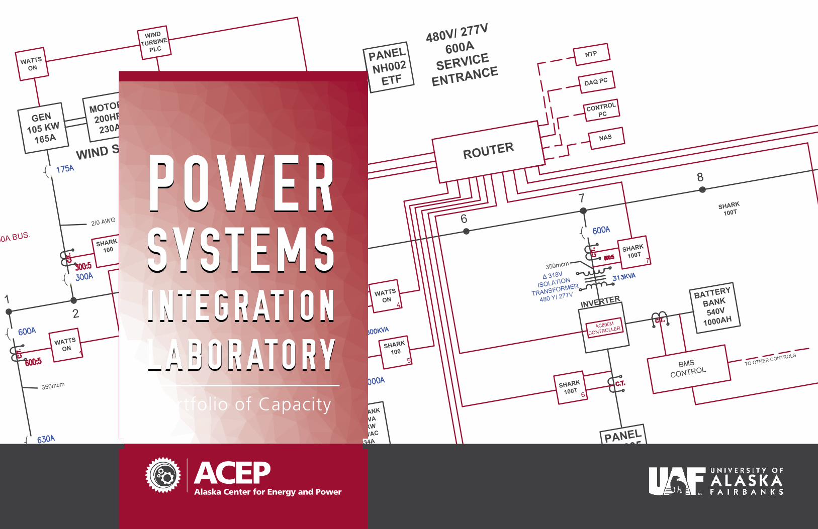
POWER SYSTEMS INTEGRATION LABORATORY
Alaska Center for Energy and Power
Portfolio of Capacity
ii
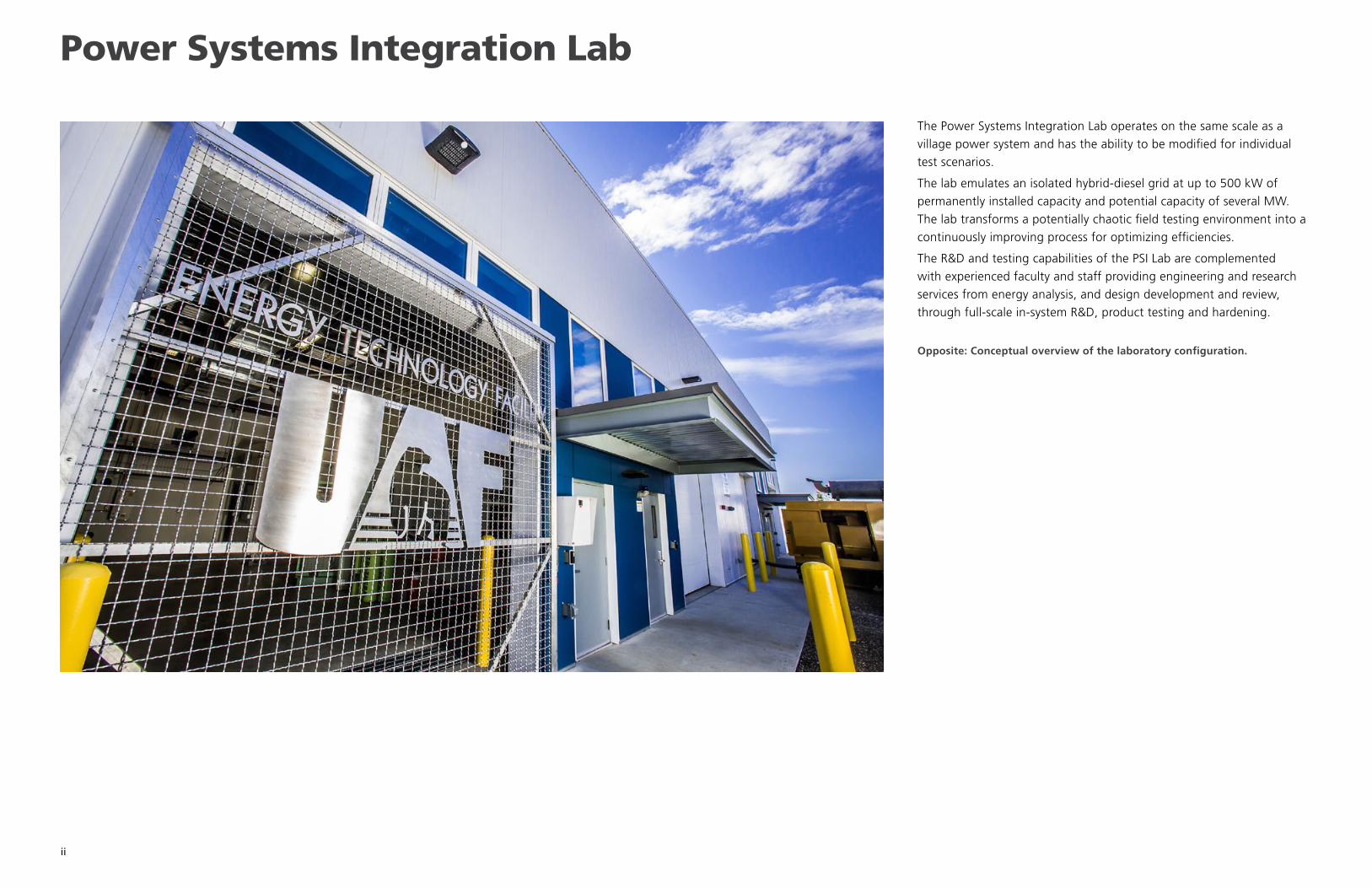
The Power Systems Integration Lab operates on the same scale as a
village power system and has the ability to be modified for individual
test scenarios.
The lab emulates an isolated hybrid-diesel grid at up to 500 kW of
permanently installed capacity and potential capacity of several MW.
The lab transforms a potentially chaotic field testing environment into a
continuously improving process for optimizing efficiencies.
The R&D and testing capabilities of the PSI Lab are complemented
with experienced faculty and staff providing engineering and research
services from energy analysis, and design development and review,
through full-scale in-system R&D, product testing and hardening.
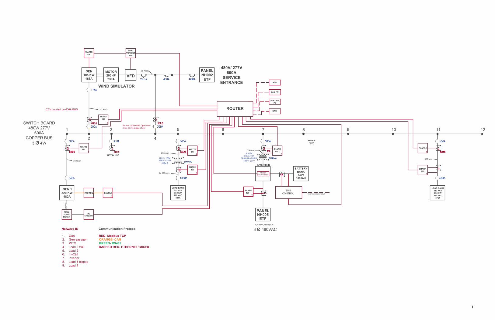
Opposite: Conceptual overview of the laboratory configuration.
Power Systems Integration Lab
1234 15678
78 6 5 4 3 2 1
BA
CD
BA
CD
POWER SYSTEMS INTEGRATION LABPROJECT:
DRAFTER: DATE: VERSION:
350mcm
250mcm
2x 500mcm
350mcm
2/0 AWG
4/0 AWG
SWITCH BOARD480V/ 277V
600ACOPPER BUS
3 Ø 4W
GEN 1320 KW
482A
LOAD BANK313 KVA250 KW208 VAC
834A
LOAD BANK313 KVA250 KW480 VAC
376A
GEN105 KW
165A
MOTOR200HP230A
VFD
WIND SIMULATOR
PANELNH002
ETF
480V/ 277V600A
SERVICEENTRANCE
Service connection. Open whenmicro-grid is in operation
208 Y/ 120VSTEP DOWN
480V Δ
1
2
3
4
5 6
CT's Located on 600A BUS.
7 8 98 10 11 12
ROUTER
NTP
DAQ PC
CONTROLPC
NAS
SHARK100
WATTSON
ESEGEN ESENET
SHARK100
WATTSON
SHARK100T
ELSPEC
SHARK100
*NOT IN USE
AC800MCONTROLLER
TO OTHER CONTROLS
PANELNH005
ETF
INVERTERBATTERY
BANK540V
1000AH
SHARK100T
SHARK100T
FUELFLOW
METER
1
2
3
4
5
6
7
9
1. Gen2. Gen easygen3. WTG4. Load 2 WO5. Load 26. InvCtrl7. Inverter8. Load 1 elspec9. Load 1
3 Ø 480VAC
MBGATEWAY
WATTSON
WINDTURBINE
PLC
8
Network ID Communication Protocol
RED- Modbus TCPORANGE- CANGREEN- RS485DASHED RED- ETHERNET/ MIXED
PSI NETWORK LAYOUT
NICK KONEFAL 2-23-2015 1.0
2
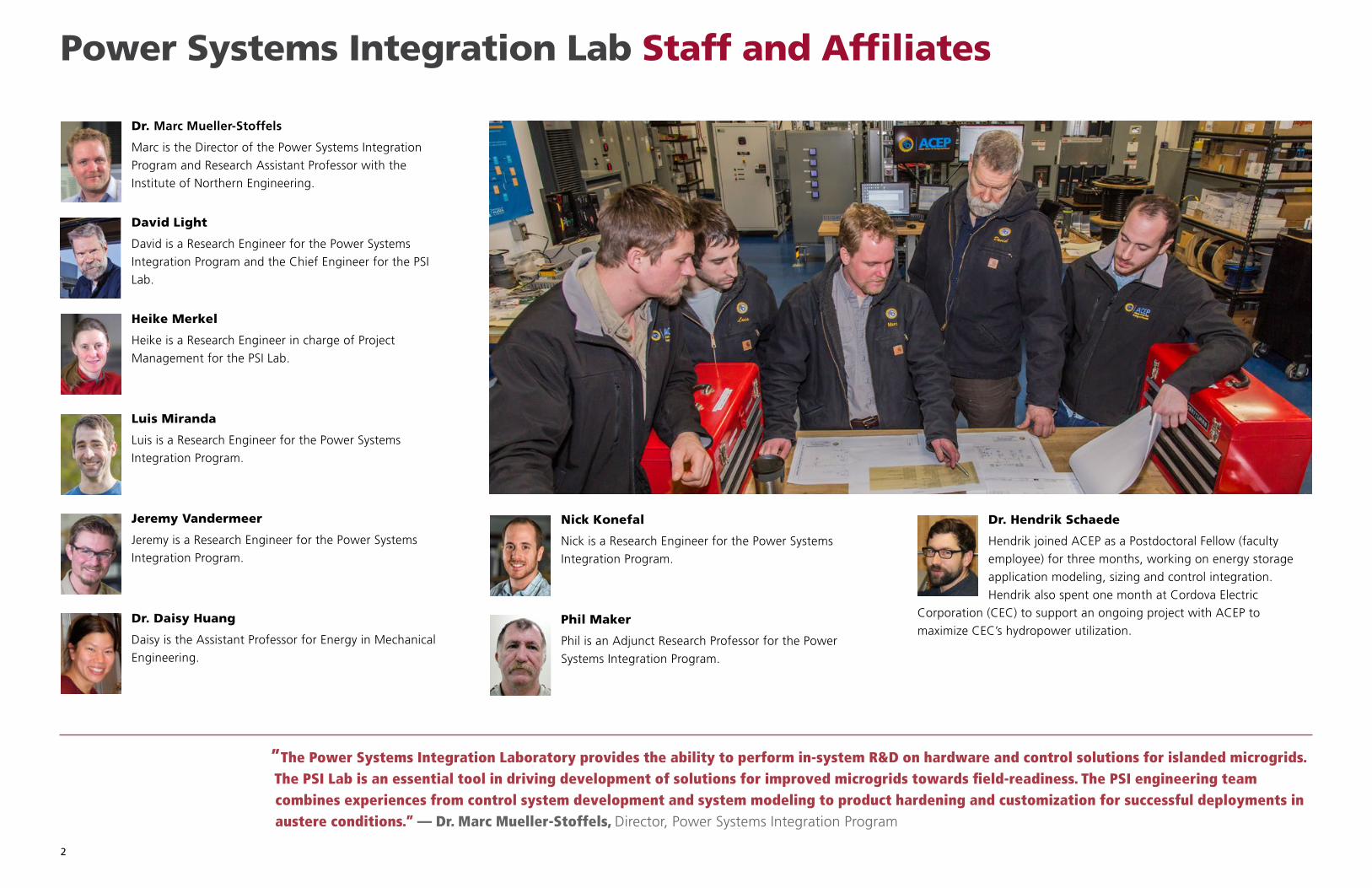
Dr. Marc Mueller-Stoffels
Marc is the Director of the Power Systems Integration
Program and Research Assistant Professor with the
Institute of Northern Engineering.
David Light
David is a Research Engineer for the Power Systems
Integration Program and the Chief Engineer for the PSI
Lab.
Heike Merkel
Heike is a Research Engineer in charge of Project
Management for the PSI Lab.
Luis Miranda
Luis is a Research Engineer for the Power Systems
Integration Program.
Jeremy Vandermeer
Jeremy is a Research Engineer for the Power Systems
Integration Program.
Dr. Daisy Huang
Daisy is the Assistant Professor for Energy in Mechanical
Engineering.
Nick Konefal
Nick is a Research Engineer for the Power Systems
Integration Program.
Phil Maker
Phil is an Adjunct Research Professor for the Power
Systems Integration Program.
Power Systems Integration Lab Staff and Affiliates
Dr. Hendrik Schaede
Hendrik joined ACEP as a Postdoctoral Fellow (faculty
employee) for three months, working on energy storage
application modeling, sizing and control integration.
Hendrik also spent one month at Cordova Electric
Corporation (CEC) to support an ongoing project with ACEP to
maximize CEC’s hydropower utilization.
”The Power Systems Integration Laboratory provides the ability to perform in-system R&D on hardware and control solutions for islanded microgrids. The PSI Lab is an essential tool in driving development of solutions for improved microgrids towards field-readiness. The PSI engineering team combines experiences from control system development and system modeling to product hardening and customization for successful deployments in austere conditions.” — Dr. Marc Mueller-Stoffels, Director, Power Systems Integration Program
3
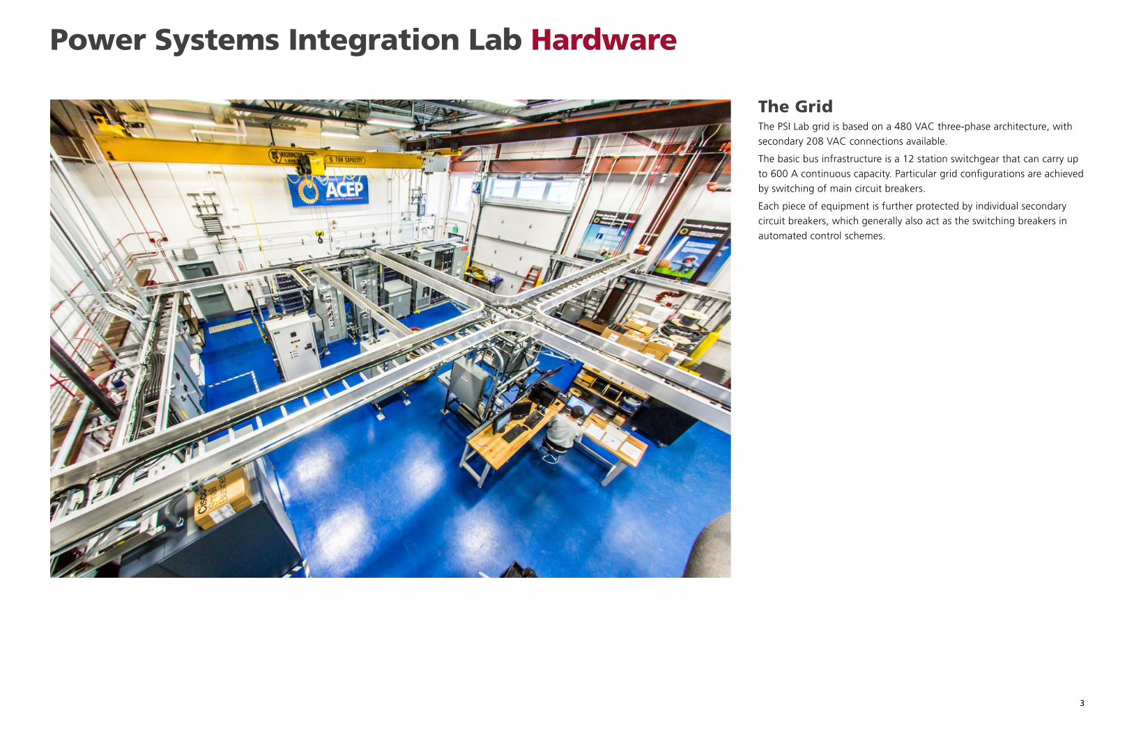
Power Systems Integration Lab Hardware
The GridThe PSI Lab grid is based on a 480 VAC three-phase architecture, with
secondary 208 VAC connections available.
The basic bus infrastructure is a 12 station switchgear that can carry up
to 600 A continuous capacity. Particular grid configurations are achieved
by switching of main circuit breakers.
Each piece of equipment is further protected by individual secondary
circuit breakers, which generally also act as the switching breakers in
automated control schemes.
4
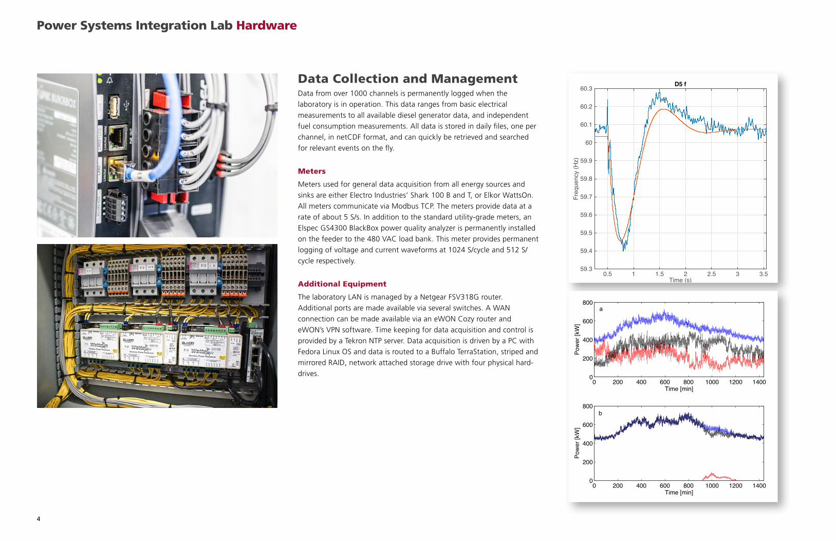
Data Collection and ManagementData from over 1000 channels is permanently logged when the
laboratory is in operation. This data ranges from basic electrical
measurements to all available diesel generator data, and independent
fuel consumption measurements. All data is stored in daily files, one per
channel, in netCDF format, and can quickly be retrieved and searched
for relevant events on the fly.
Meters
Meters used for general data acquisition from all energy sources and
sinks are either Electro Industries’ Shark 100 B and T, or Elkor WattsOn.
All meters communicate via Modbus TCP. The meters provide data at a
rate of about 5 S/s. In addition to the standard utility-grade meters, an
Elspec GS4300 BlackBox power quality analyzer is permanently installed
on the feeder to the 480 VAC load bank. This meter provides permanent
logging of voltage and current waveforms at 1024 S/cycle and 512 S/
cycle respectively.
Additional Equipment
The laboratory LAN is managed by a Netgear FSV318G router.
Additional ports are made available via several switches. A WAN
connection can be made available via an eWON Cozy router and
eWON’s VPN software. Time keeping for data acquisition and control is
provided by a Tekron NTP server. Data acquisition is driven by a PC with
Fedora Linux OS and data is routed to a Buffalo TerraStation, striped and
mirrored RAID, network attached storage drive with four physical hard-
drives.
Power Systems Integration Lab Hardware
Time (s)0.5 1 1.5 2 2.5 3 3.5
Freq
uenc
y (H
z)
59.3
59.4
59.5
59.6
59.7
59.8
59.9
60
60.1
60.2
60.3 D5 f
0 200 400 600 800 1000 1200 14000
200
400
600
800
Time [min]
Pow
er [k
W]
0 200 400 600 800 1000 1200 14000
200
400
600
800
Time [min]
Pow
er [k
W]
a
b
5
Custom Control Architecture
The ETF SCADA is a Supervisory Control and Data Acquisition (SCADA)
system, developed by ACEP to control the Energy Technology Facility
(ETF) power generation and permanently monitor all available data
channels.
It is a modular software composed of two separate programs:
• Data Acquisition (DA) module, responsible for requesting data from
each individual device and broadcasting the data throughout the
network;
• Supervisor Control (SC) module, receives the data from a DA module,
which afterwards processes, catalogues and analyses the data in order
to check if the values are within compliance or if an operator should
be notified.
The ETF SCADA was designed to be fully customizable, adapting to any
device that uses the Modbus TCP protocol. It is intended to enable users
to automate the data collection, visualization and also automatically
check if any variables are outside the acceptable range. It does not
require a facility to have all their Modbus TCP devices from the same
brand.
Data Acquisition Module
The DA module is able to handle the devices independently, in order
to maximize the sampling frequency and minimize any maintenance
or eventual malfunction downtime. In practice, this allows for plug
and play connectivity from the devices, as soon as they appear in the
network, the data collection is seamlessly resumed, without requiring
any further input. The most typical limitation on the sampling speed is
due to the device response time.
Experimentally we were able to collect data as fast as 400Hz, with
better device hardware. Note that since this was not tested on a Real
Time Operative System (RTOS) the resulting jitter was very significant,
resulting in an average sampling frequency of 250Hz.
The typical hardware response times and Modbus maps limit the data
collection from 3 to 5Hz, but this always depends on the specific device.
The Data is stored in netCDF files, intrinsically coupling the metadata
to the collected data, so that the datasets always retain their original
information.
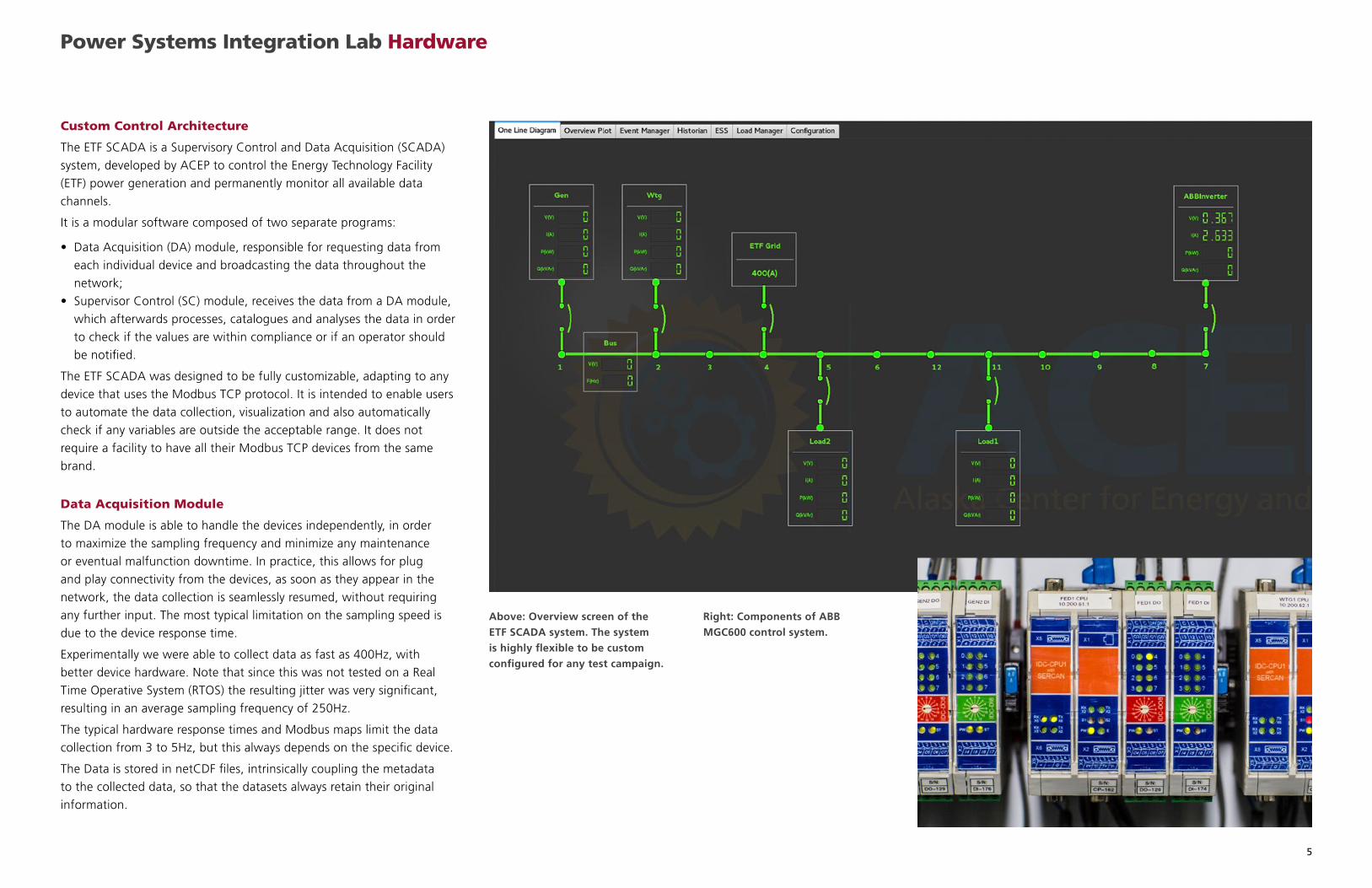
Above: Overview screen of the ETF SCADA system. The system is highly flexible to be custom configured for any test campaign.
Right: Components of ABB MGC600 control system.
Power Systems Integration Lab Hardware
6
Supervisory Control Module
This module can act as a passive terminal, collecting the data sent from
a DA module. In this configuration the DA module can send data to an
unlimited number of terminals.
The SC module can be configured, e.g., by adding limits to certain
variables. The limits can be set as mathematical expression (including
a potential time difference between 2 values), as level indication the
severity of an event or to differentiate between reports and alarms, or as
a tag for human readability.
If limits are set, the event manager is able to list past events along with
all relevant information. The user can double click on a past event,
which opens a dataset in that period with an actual tag from when the
event was raised. Data can be cross-referenced from several devices and
plotted in one single graph. Any variables from any device can be added
to the plot.
Furthermore, in the SC module the sample frequency that is received
from the DA module can be limited, the temporal display can be scaled,
and the declared network devices can be viewed.
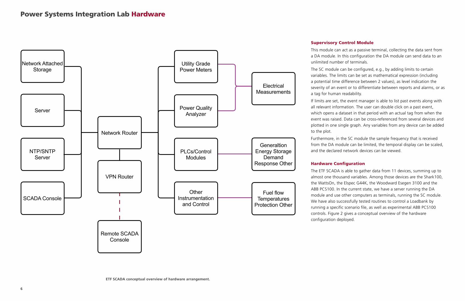
Hardware Configuration
The ETF SCADA is able to gather data from 11 devices, summing up to
almost one thousand variables. Among those devices are the Shark100,
the WattsOn, the Elspec G44K, the Woodward Esegen 3100 and the
ABB PCS100. In the current state, we have a server running the DA
module and use other computers as terminals, running the SC module.
We have also successfully tested routines to control a Loadbank by
running a specific scenario file, as well as experimental ABB PCS100
controls. Figure 2 gives a conceptual overview of the hardware
configuration deployed.
ETF SCADA conceptual overview of hardware arrangement.
Power Systems Integration Lab Hardware
Network Attached Storage
Server
Network Router
Utility Grade Power Meters
Electrical Measurements
Generaltion Energy Storage
Demand Response Other
Fuel flow Temperatures
Protection Other
Power Quality Analyzer
PLCs/Control Modules
Other Instrumentation
and Control
VPN Router
Remote SCADA Console
NTP/SNTP Server
SCADA Console
7
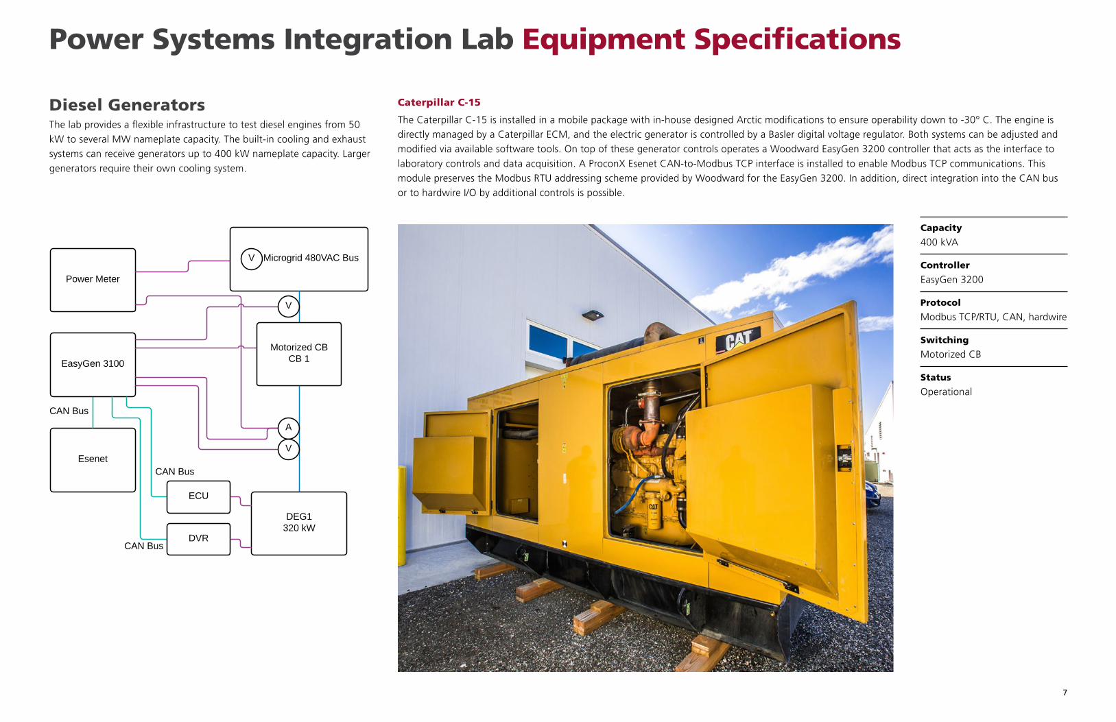
Diesel GeneratorsThe lab provides a flexible infrastructure to test diesel engines from 50
kW to several MW nameplate capacity. The built-in cooling and exhaust
systems can receive generators up to 400 kW nameplate capacity. Larger
generators require their own cooling system.
Caterpillar C-15
The Caterpillar C-15 is installed in a mobile package with in-house designed Arctic modifications to ensure operability down to -30° C. The engine is
directly managed by a Caterpillar ECM, and the electric generator is controlled by a Basler digital voltage regulator. Both systems can be adjusted and
modified via available software tools. On top of these generator controls operates a Woodward EasyGen 3200 controller that acts as the interface to
laboratory controls and data acquisition. A ProconX Esenet CAN-to-Modbus TCP interface is installed to enable Modbus TCP communications. This
module preserves the Modbus RTU addressing scheme provided by Woodward for the EasyGen 3200. In addition, direct integration into the CAN bus
or to hardwire I/O by additional controls is possible.
Capacity
400 kVA
Controller
EasyGen 3200
Protocol
Modbus TCP/RTU, CAN, hardwire
Switching
Motorized CB
Status
Operational
Power Systems Integration Lab Equipment Specifications
8
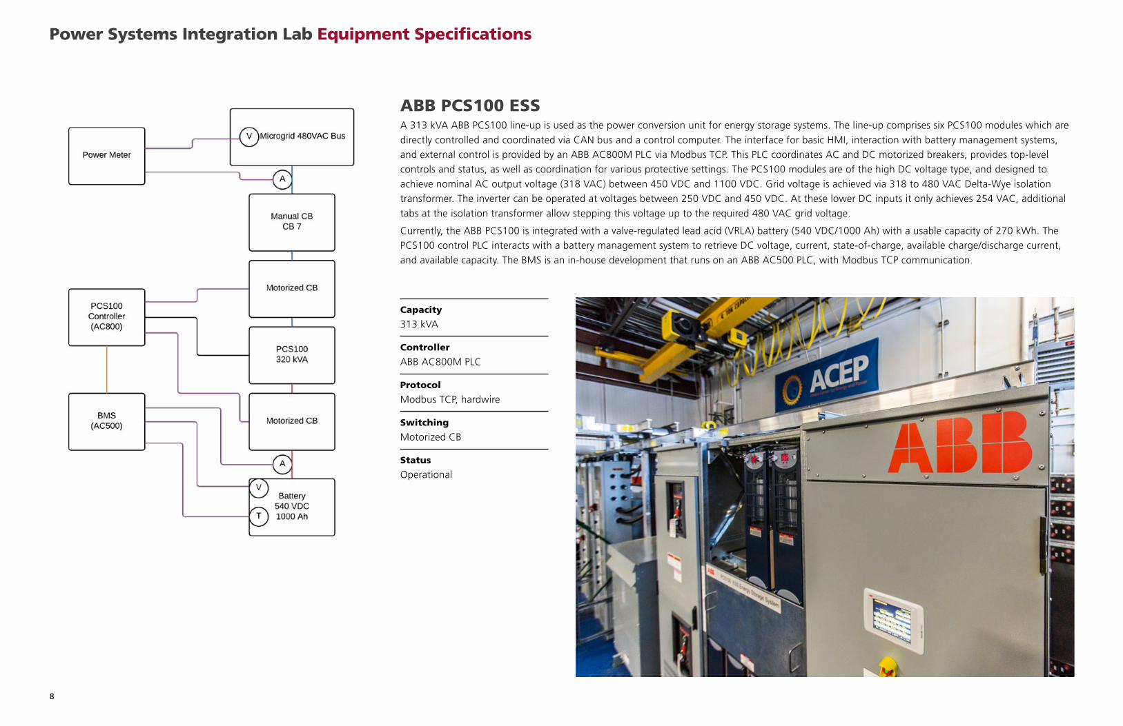
ABB PCS100 ESSA 313 kVA ABB PCS100 line-up is used as the power conversion unit for energy storage systems. The line-up comprises six PCS100 modules which are
directly controlled and coordinated via CAN bus and a control computer. The interface for basic HMI, interaction with battery management systems,
and external control is provided by an ABB AC800M PLC via Modbus TCP. This PLC coordinates AC and DC motorized breakers, provides top-level
controls and status, as well as coordination for various protective settings. The PCS100 modules are of the high DC voltage type, and designed to
achieve nominal AC output voltage (318 VAC) between 450 VDC and 1100 VDC. Grid voltage is achieved via 318 to 480 VAC Delta-Wye isolation
transformer. The inverter can be operated at voltages between 250 VDC and 450 VDC. At these lower DC inputs it only achieves 254 VAC, additional
tabs at the isolation transformer allow stepping this voltage up to the required 480 VAC grid voltage.
Currently, the ABB PCS100 is integrated with a valve-regulated lead acid (VRLA) battery (540 VDC/1000 Ah) with a usable capacity of 270 kWh. The
PCS100 control PLC interacts with a battery management system to retrieve DC voltage, current, state-of-charge, available charge/discharge current,
and available capacity. The BMS is an in-house development that runs on an ABB AC500 PLC, with Modbus TCP communication.
Capacity
313 kVA
Controller
ABB AC800M PLC
Protocol
Modbus TCP, hardwire
Switching
Motorized CB
Status
Operational
Power Systems Integration Lab Equipment Specifications
9
Power Systems Integration Lab Equipment Specifications
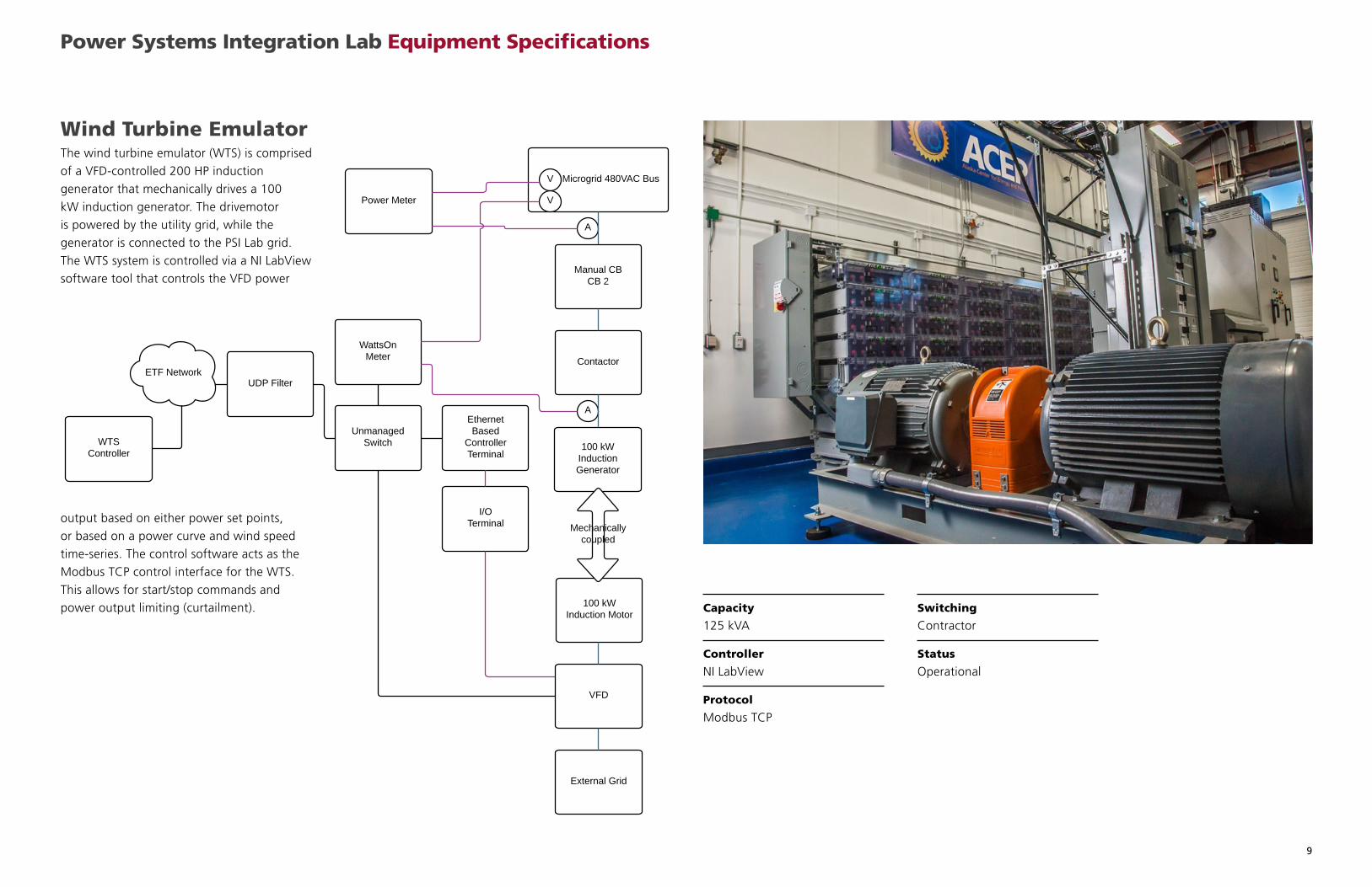
Capacity
125 kVA
Controller
NI LabView
Protocol
Modbus TCP
Switching
Contractor
Status
Operational
Wind Turbine EmulatorThe wind turbine emulator (WTS) is comprised
of a VFD-controlled 200 HP induction
generator that mechanically drives a 100
kW induction generator. The drivemotor
is powered by the utility grid, while the
generator is connected to the PSI Lab grid.
The WTS system is controlled via a NI LabView
software tool that controls the VFD power
output based on either power set points,
or based on a power curve and wind speed
time-series. The control software acts as the
Modbus TCP control interface for the WTS.
This allows for start/stop commands and
power output limiting (curtailment).
10
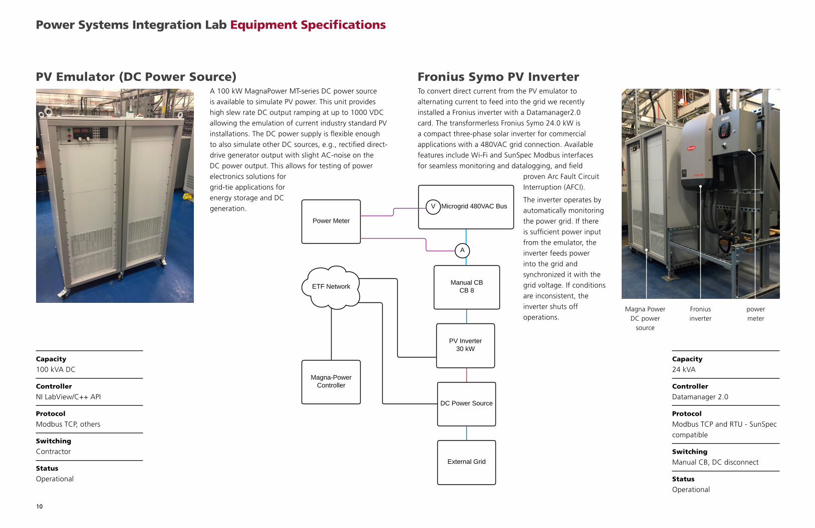
Capacity
100 kVA DC
Controller
NI LabView/C++ API
Protocol
Modbus TCP, others
Switching
Contractor
Status
Operational
PV Emulator (DC Power Source)A 100 kW MagnaPower MT-series DC power source
is available to simulate PV power. This unit provides
high slew rate DC output ramping at up to 1000 VDC
allowing the emulation of current industry standard PV
installations. The DC power supply is flexible enough
to also simulate other DC sources, e.g., rectified direct-
drive generator output with slight AC-noise on the
DC power output. This allows for testing of power
electronics solutions for
grid-tie applications for
energy storage and DC
generation.
Power Systems Integration Lab Equipment Specifications
Fronius Symo PV InverterTo convert direct current from the PV emulator to
alternating current to feed into the grid we recently
installed a Fronius inverter with a Datamanager2.0
card. The transformerless Fronius Symo 24.0 kW is
a compact three-phase solar inverter for commercial
applications with a 480VAC grid connection. Available
features include Wi-Fi and SunSpec Modbus interfaces
for seamless monitoring and datalogging, and field
proven Arc Fault Circuit
Interruption (AFCI).
The inverter operates by
automatically monitoring
the power grid. If there
is sufficient power input
from the emulator, the
inverter feeds power
into the grid and
synchronized it with the
grid voltage. If conditions
are inconsistent, the
inverter shuts off
operations.
Capacity
24 kVA
Controller
Datamanager 2.0
Protocol
Modbus TCP and RTU - SunSpec
compatible
Switching
Manual CB, DC disconnect
Status
Operational
Magna Power DC power
source
Fronius inverter
power meter
11
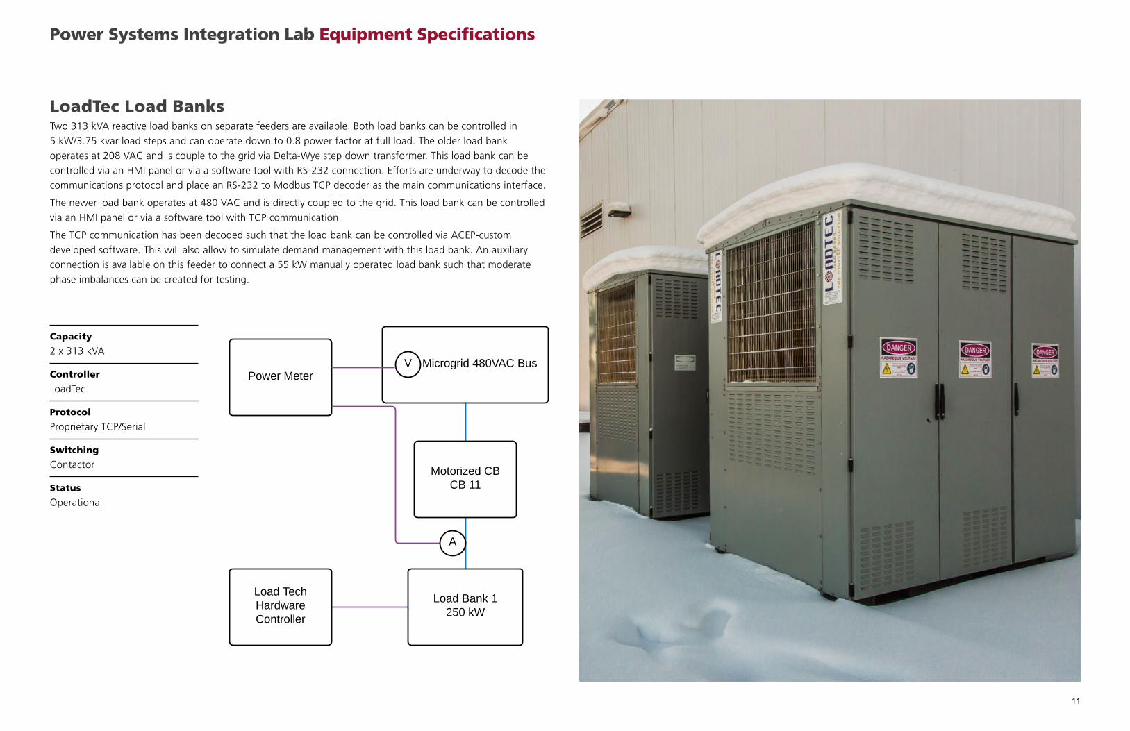
Capacity
2 x 313 kVA
Controller
LoadTec
Protocol
Proprietary TCP/Serial
Switching
Contactor
Status
Operational
LoadTec Load BanksTwo 313 kVA reactive load banks on separate feeders are available. Both load banks can be controlled in
5 kW/3.75 kvar load steps and can operate down to 0.8 power factor at full load. The older load bank
operates at 208 VAC and is couple to the grid via Delta-Wye step down transformer. This load bank can be
controlled via an HMI panel or via a software tool with RS-232 connection. Efforts are underway to decode the
communications protocol and place an RS-232 to Modbus TCP decoder as the main communications interface.
The newer load bank operates at 480 VAC and is directly coupled to the grid. This load bank can be controlled
via an HMI panel or via a software tool with TCP communication.
The TCP communication has been decoded such that the load bank can be controlled via ACEP-custom
developed software. This will also allow to simulate demand management with this load bank. An auxiliary
connection is available on this feeder to connect a 55 kW manually operated load bank such that moderate
phase imbalances can be created for testing.
Power Systems Integration Lab Equipment Specifications
12
Power Systems Integration Lab Expansion Plans
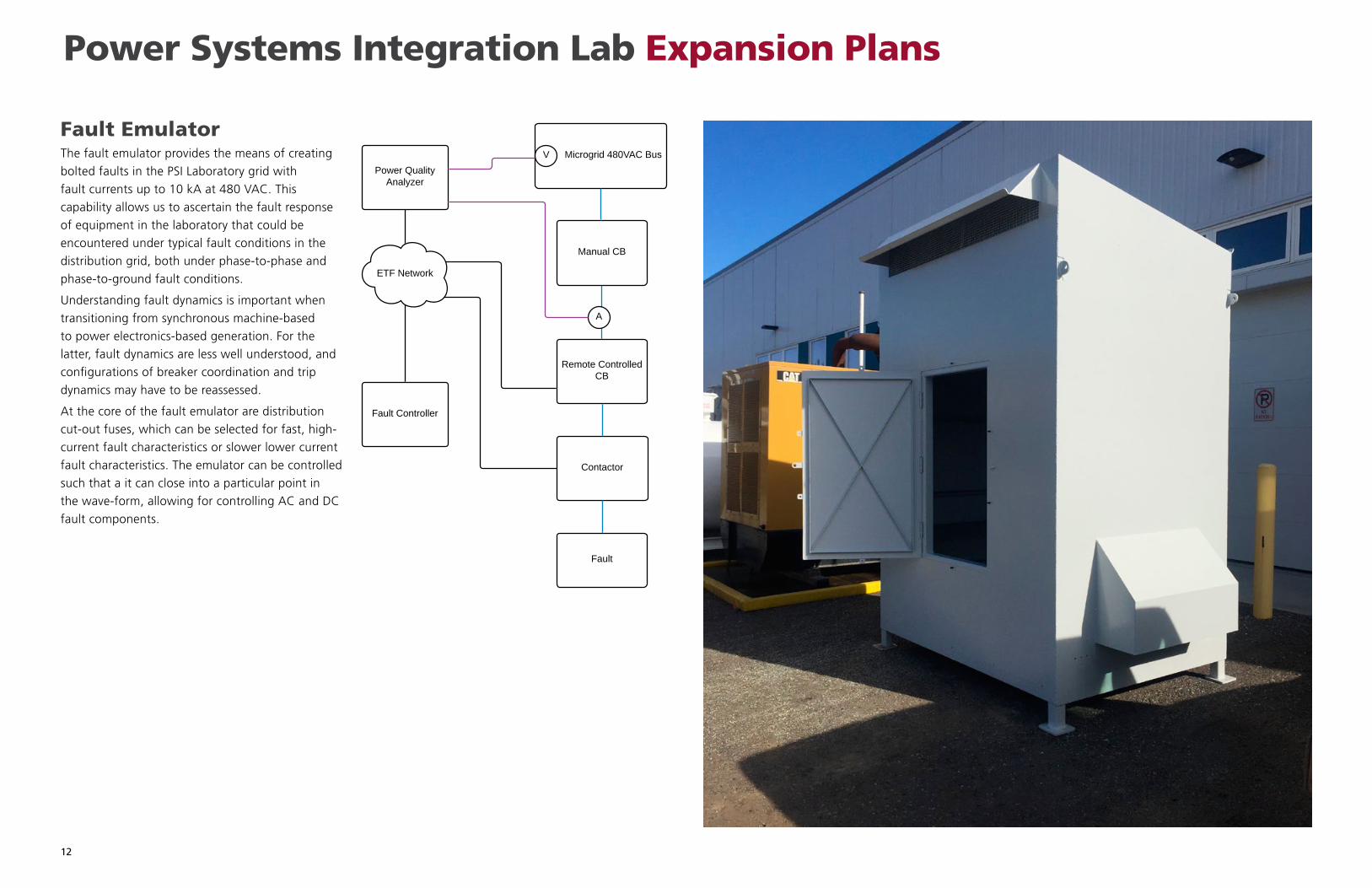
Fault EmulatorThe fault emulator provides the means of creating
bolted faults in the PSI Laboratory grid with
fault currents up to 10 kA at 480 VAC. This
capability allows us to ascertain the fault response
of equipment in the laboratory that could be
encountered under typical fault conditions in the
distribution grid, both under phase-to-phase and
phase-to-ground fault conditions.
Understanding fault dynamics is important when
transitioning from synchronous machine-based
to power electronics-based generation. For the
latter, fault dynamics are less well understood, and
configurations of breaker coordination and trip
dynamics may have to be reassessed.
At the core of the fault emulator are distribution
cut-out fuses, which can be selected for fast, high-
current fault characteristics or slower lower current
fault characteristics. The emulator can be controlled
such that a it can close into a particular point in
the wave-form, allowing for controlling AC and DC
fault components.
13
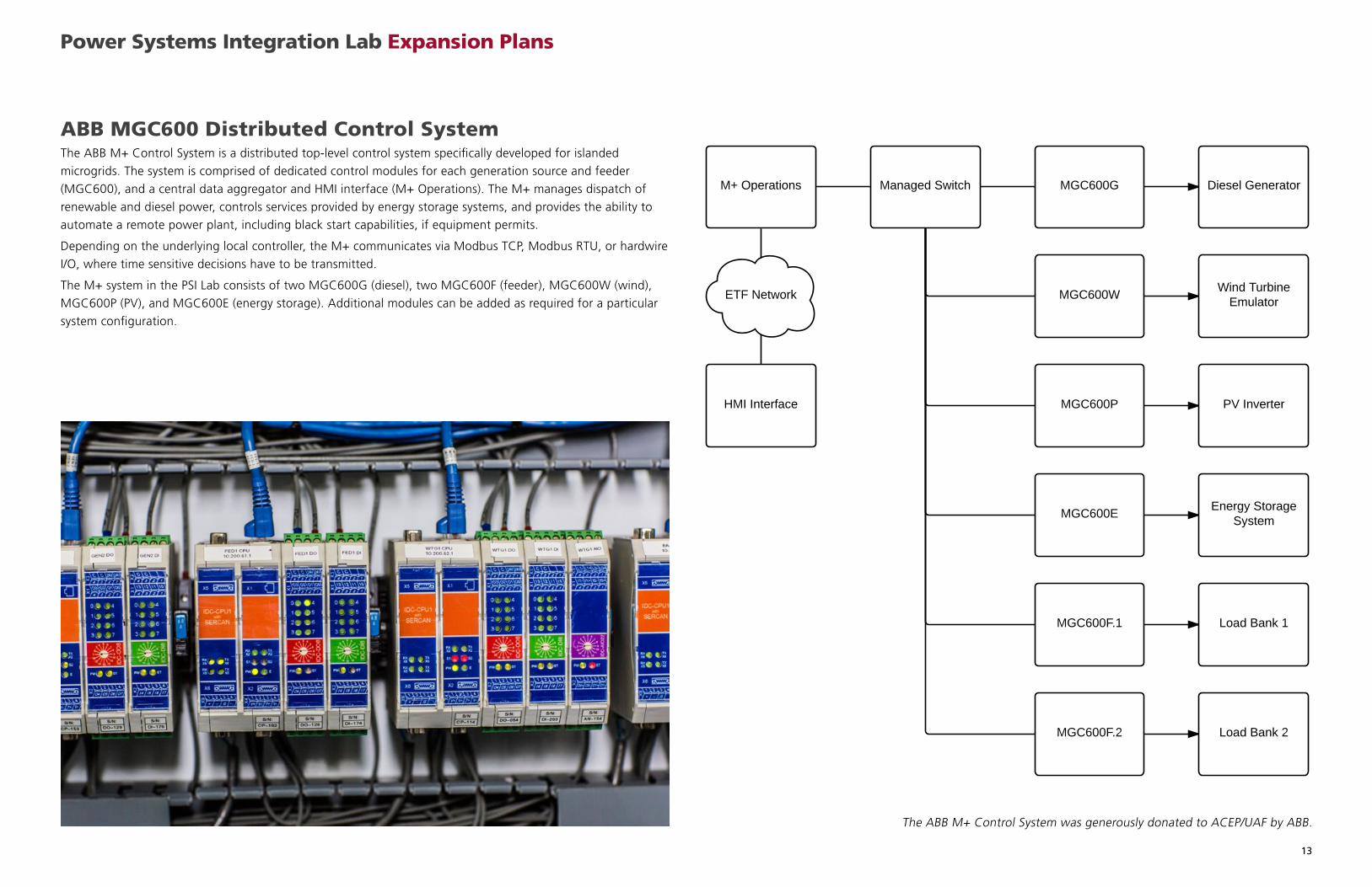
ABB MGC600 Distributed Control SystemThe ABB M+ Control System is a distributed top-level control system specifically developed for islanded
microgrids. The system is comprised of dedicated control modules for each generation source and feeder
(MGC600), and a central data aggregator and HMI interface (M+ Operations). The M+ manages dispatch of
renewable and diesel power, controls services provided by energy storage systems, and provides the ability to
automate a remote power plant, including black start capabilities, if equipment permits.
Depending on the underlying local controller, the M+ communicates via Modbus TCP, Modbus RTU, or hardwire
I/O, where time sensitive decisions have to be transmitted.
The M+ system in the PSI Lab consists of two MGC600G (diesel), two MGC600F (feeder), MGC600W (wind),
MGC600P (PV), and MGC600E (energy storage). Additional modules can be added as required for a particular
system configuration.
Power Systems Integration Lab Expansion Plans
The ABB M+ Control System was generously donated to ACEP/UAF by ABB.
14
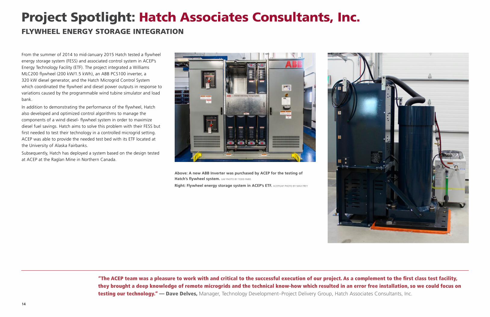
From the summer of 2014 to mid-January 2015 Hatch tested a flywheel
energy storage system (FESS) and associated control system in ACEP’s
Energy Technology Facility (ETF). The project integrated a Williams
MLC200 flywheel (200 kW/1.5 kWh), an ABB PCS100 inverter, a
320 kW diesel generator, and the Hatch Microgrid Control System
which coordinated the flywheel and diesel power outputs in response to
variations caused by the programmable wind tubine simulator and load
bank.
In addition to demonstrating the performance of the flywheel, Hatch
also developed and optimized control algorithms to manage the
components of a wind diesel- flywheel system in order to maximize
diesel fuel savings. Hatch aims to solve this problem with their FESS but
first needed to test their technology in a controlled microgrid setting.
ACEP was able to provide the needed test bed with its ETF located at
the University of Alaska Fairbanks.
Subsequently, Hatch has deployed a system based on the design tested
at ACEP at the Raglan Mine in Northern Canada.
Above: A new ABB Inverter was purchased by ACEP for the testing of Hatch’s flywheel system. UAF PHOTO BY TODD PARIS
Right: Flywheel energy storage system in ACEP’s ETF. ACEP/UAF PHOTO BY MAX FREY
“The ACEP team was a pleasure to work with and critical to the successful execution of our project. As a complement to the first class test facility, they brought a deep knowledge of remote microgrids and the technical know-how which resulted in an error free installation, so we could focus on testing our technology.” — Dave Delves, Manager, Technology Development–Project Delivery Group, Hatch Associates Consultants, Inc.
Project Spotlight: Hatch Associates Consultants, Inc.FLYWHEEL ENERGY STORAGE INTEGRATION

15
Project Need
Historically, Cordova's hydropower has been sufficient to meet nearly all demand
during the summer months. However, recent increases in energy demand from
the fish processing industry has exceeded the capacity of the hydropower plants,
forcing CEC to supplement with diesel generation.
Currently, when hydropower is the sole generation source, one 3 MW
hydropower turbine is used for frequency regulation, which results in a reduction
of 500 kW of available capacity. While hydropower capacity is not sufficient to
meet daytime demand, the hydropower plants do not operate at full capacity
during off-peak hours. Since these hydropower systems do not include dams that
provide water storage, the water that is normally diverted for power generation
is simply spilled down the creeks. The result is significant loss of potential power
production and, thus, power sales from a very cheap generation resource. The
need for alternative frequency regulation services, along with the desire to
maximize the use of hydropower, is the impetus for this study, which assesses
the technical and economic feasibility of achieving maximal hydropower use via
energy storage and demand response technologies.
Initial assessments show that in 2012/2013, over 2,000 MWh of potential
hydropower production were not realized due to demand being below
hydropower capacity. While it is not certain that the full amount of lost
production is recoverable, this gives a tangible initial economic case to further
explore possible solutions.
Project Description
Research partners are analyzing data provided by CEC to better understand
the economic potential of an energy storage and demand response solution to
utilize this spilled energy. An energy balance model (EBM) has been employed to
model the generation and demand mix and to develop a range of scenarios that
optimally incorporate energy storage and demand response solutions. Maximum
value of an energy storage and demand response system can be achieved only
if it precludes diesel generation during peak demand periods, so load growth
scenarios will be added to the model to understand the future value of a
solution.
The goal of the EBM is to understand the value of making the additional 500
kW of hydropower generation available to meet energy demand and creating an
energy storage solution to shift generation from peak to off-peak periods and
assessing how off-peak demand can be increased while reducing peak demand
through demand response solutions. Based on model results, possible energy
storage and demand response solutions for both applications will be identified
and incorporated into the EBM, facilitating recommendations for optimal sizing
and scheduling.
Furthermore, ACEP researchers have studied the potential and options for
installing controlled electro-thermal loads at the Orca Diesel Power Plant and the
Bob Korn Memorial swimming pool in Cordova. The Orca plant currently utilizes
diesel-fueled boilers to keep engines in hot standby when the grid is running
on 100% hydropower, which results in fuel costs for heat of over $80,000/year
(2014 numbers). Similarly, the swimming pool requires over 16,000 gal/year of
diesel fuel for heat. Utility-dispatched electric heaters that would supplement
heating loops when excess hydropower is available, may significantly reduce
diesel fuel use. Conceptual designs developed by ACEP incorporating efficiency
upgrades and thermal storage systems may reduce fuel use by over 20,000 gal/
year for both systems.
“ACEP is more than a capable team…more like a high-functioning unit; the Seal Team 6 of Energy and Power. Half of the energy industry claims to have smartgrid and energy storage solutions, but for our community’s remote micro grid system in our rugged environment, we turn to ACEP with our complex technical challenges, because promises and theories don’t keep the lights on.” Clay Koplin, CEO, Cordova Electric Cooperative
Project Spotlight: Cordova Electric CooperativeHYDROPOWER ENERGY STORAGE AND DEMAND RESPONSE SOLUTIONS

16
Project Description
The project goal was to provide Nome Joint Utility Services (NJUS)
with data analysis, models, and additional information to support
technical and economic decision-making processes. The Power Systems
Integration Program directly provides technical information to NJUS, and
informs the Economic Analysis Group at ACEP of technical information
relevant for economic modeling. The first phase was concerned with
the interaction of energy resources (wind, geothermal, and diesel), to
understand the impact of several generation scenarios on the overall
amount of wind power that can be added to the grid, with risk of
under-loading diesel generators. Since NJUS recently added additional
wind resources and new diesel gensets, existing historic data could
not be directly employed to drive model development. Statistical
methods were employed to extrapolate wind power output from the
extended wind farm. This data was fed into a time-series energy balance
model (TSEBM). The TSEBM matched energy generation with demand
while considering the operational envelope of the diesel generators
(scheduling and minimum and maximum optimal loading) and general
grid stability. Information gained from TSEBM outputs showed the
amount of wind power that cannot be admitted to the grid (spilled
wind) and the optimal diesel-scheduling scheme based on current
generation assets. The second phase explored how energy storage
solutions may be used to:
• ensure greater grid stability and power quality, should that be
required, and
• determine if an energy storage solution can economically reduce the
use of diesel fuel by replacing the spinning reserve generally provided
by a diesel generator.
Project Results
Different capacities of geothermal plants were simulated. Adding
geothermal generation to the grid reduced the amount of wind power
that could be admitted into the grid (increased spilled wind), thus there
was a diminishing return for increasing geothermal generation. Above
2.75 MW of geothermal capacity the incremental reduction in diesel
generation dropped off sharply, as significant amounts of renewable
energy went unused. Scenarios where smaller diesel generators were
added to the grid resulted in a greater reduction in diesel generation.
Scenarios where energy storage was added to the grid to supply
spinning reserve resulted in a greater reduction in diesel generation and
reduced some of the stress on the diesel generators induced by adding
geothermal generation.
“ACEP’s breadth of technical expertise has been extremely helpful on a range of issues from alternative energy integration to resource evaluation and economic analysis of our energy options. It has been vital to have the ability to partner with ACEP on our energy projects, and I look forward to continuing to work together closely in the future.” — John Handeland, General Manager/COO, Nome Joint Utility System
Project Spotlight: Nome Joint Utility ServicesGEOTHERMAL RESOURCE INTEGRATION WITH A COMMUNITY POWER GRID
17
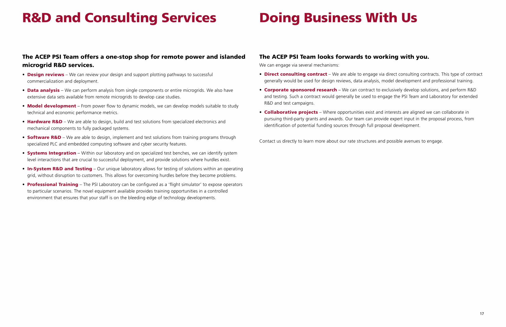
R&D and Consulting Services
The ACEP PSI Team offers a one-stop shop for remote power and islanded microgrid R&D services.
• Design reviews – We can review your design and support plotting pathways to successful
commercialization and deployment.
• Data analysis – We can perform analysis from single components or entire microgrids. We also have
extensive data sets available from remote microgrids to develop case studies.
• Model development – From power flow to dynamic models, we can develop models suitable to study
technical and economic performance metrics.
• Hardware R&D – We are able to design, build and test solutions from specialized electronics and
mechanical components to fully packaged systems.
• Software R&D – We are able to design, implement and test solutions from training programs through
specialized PLC and embedded computing software and cyber security features.
• Systems Integration – Within our laboratory and on specialized test benches, we can identify system
level interactions that are crucial to successful deployment, and provide solutions where hurdles exist.
• In-System R&D and Testing – Our unique laboratory allows for testing of solutions within an operating
grid, without disruption to customers. This allows for overcoming hurdles before they become problems.
• Professional Training – The PSI Laboratory can be configured as a ‘flight simulator’ to expose operators
to particular scenarios. The novel equipment available provides training opportunities in a controlled
environment that ensures that your staff is on the bleeding edge of technology developments.
The ACEP PSI Team looks forwards to working with you. We can engage via several mechanisms:
• Direct consulting contract – We are able to engage via direct consulting contracts. This type of contract
generally would be used for design reviews, data analysis, model development and professional training.
• Corporate sponsored research – We can contract to exclusively develop solutions, and perform R&D
and testing. Such a contract would generally be used to engage the PSI Team and Laboratory for extended
R&D and test campaigns.
• Collaborative projects – Where opportunities exist and interests are aligned we can collaborate in
pursuing third-party grants and awards. Our team can provide expert input in the proposal process, from
identification of potential funding sources through full proposal development.
Contact us directly to learn more about our rate structures and possible avenues to engage.
Doing Business With Us
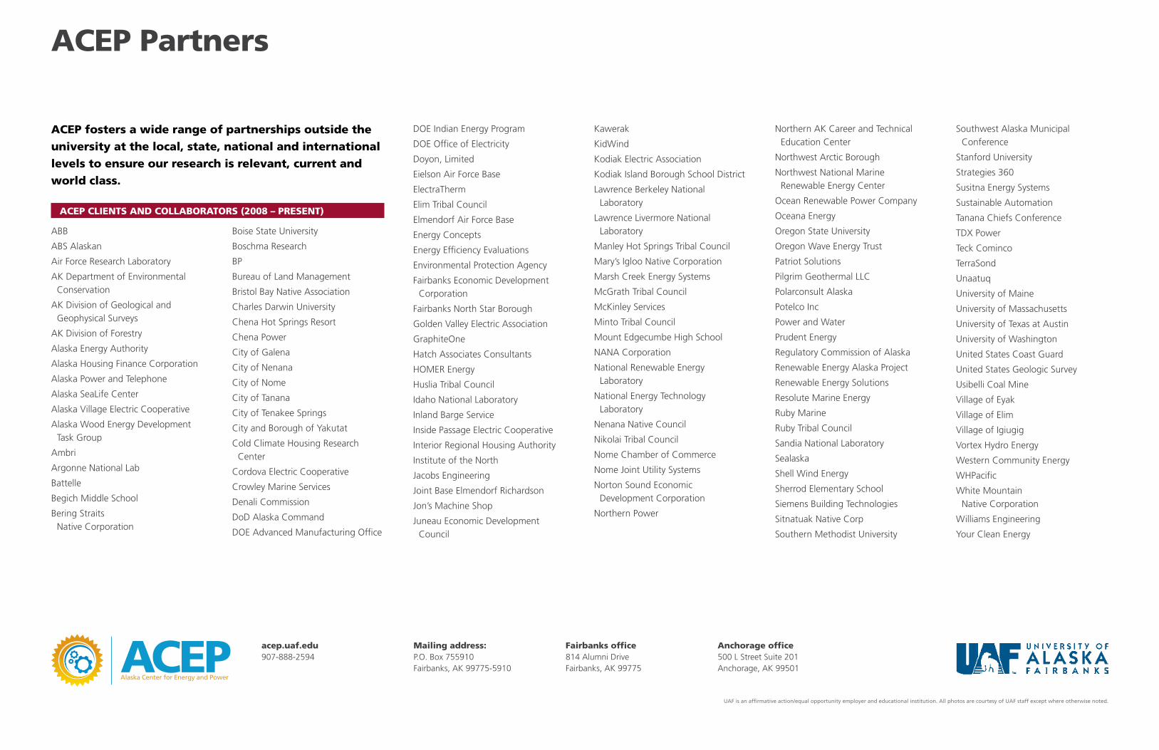
ACEP CLIENTS AND COLLABORATORS (2008 – PRESENT)
ABB
ABS Alaskan
Air Force Research Laboratory
AK Department of Environmental Conservation
AK Division of Geological and Geophysical Surveys
AK Division of Forestry
Alaska Energy Authority
Alaska Housing Finance Corporation
Alaska Power and Telephone
Alaska SeaLife Center
Alaska Village Electric Cooperative
Alaska Wood Energy Development Task Group
Ambri
Argonne National Lab
Battelle
Begich Middle School
Bering Straits Native Corporation
Boise State University
Boschma Research
BP
Bureau of Land Management
Bristol Bay Native Association
Charles Darwin University
Chena Hot Springs Resort
Chena Power
City of Galena
City of Nenana
City of Nome
City of Tanana
City of Tenakee Springs
City and Borough of Yakutat
Cold Climate Housing Research Center
Cordova Electric Cooperative
Crowley Marine Services
Denali Commission
DoD Alaska Command
DOE Advanced Manufacturing Office
DOE Indian Energy Program
DOE Office of Electricity
Doyon, Limited
Eielson Air Force Base
ElectraTherm
Elim Tribal Council
Elmendorf Air Force Base
Energy Concepts
Energy Efficiency Evaluations
Environmental Protection Agency
Fairbanks Economic Development Corporation
Fairbanks North Star Borough
Golden Valley Electric Association
GraphiteOne
Hatch Associates Consultants
HOMER Energy
Huslia Tribal Council
Idaho National Laboratory
Inland Barge Service
Inside Passage Electric Cooperative
Interior Regional Housing Authority
Institute of the North
Jacobs Engineering
Joint Base Elmendorf Richardson
Jon’s Machine Shop
Juneau Economic Development Council
Kawerak
KidWind
Kodiak Electric Association
Kodiak Island Borough School District
Lawrence Berkeley National Laboratory
Lawrence Livermore National Laboratory
Manley Hot Springs Tribal Council
Mary’s Igloo Native Corporation
Marsh Creek Energy Systems
McGrath Tribal Council
McKinley Services
Minto Tribal Council
Mount Edgecumbe High School
NANA Corporation
National Renewable Energy Laboratory
National Energy Technology Laboratory
Nenana Native Council
Nikolai Tribal Council
Nome Chamber of Commerce
Nome Joint Utility Systems
Norton Sound Economic Development Corporation
Northern Power
Northern AK Career and Technical Education Center
Northwest Arctic Borough
Northwest National Marine Renewable Energy Center
Ocean Renewable Power Company
Oceana Energy
Oregon State University
Oregon Wave Energy Trust
Patriot Solutions
Pilgrim Geothermal LLC
Polarconsult Alaska
Potelco Inc
Power and Water
Prudent Energy
Regulatory Commission of Alaska
Renewable Energy Alaska Project
Renewable Energy Solutions
Resolute Marine Energy
Ruby Marine
Ruby Tribal Council
Sandia National Laboratory
Sealaska
Shell Wind Energy
Sherrod Elementary School
Siemens Building Technologies
Sitnatuak Native Corp
Southern Methodist University
Southwest Alaska Municipal Conference
Stanford University
Strategies 360
Susitna Energy Systems
Sustainable Automation
Tanana Chiefs Conference
TDX Power
Teck Cominco
TerraSond
Unaatuq
University of Maine
University of Massachusetts
University of Texas at Austin
University of Washington
United States Coast Guard
United States Geologic Survey
Usibelli Coal Mine
Village of Eyak
Village of Elim
Village of Igiugig
Vortex Hydro Energy
Western Community Energy
WHPacific
White Mountain Native Corporation
Williams Engineering
Your Clean Energy
ACEP fosters a wide range of partnerships outside the university at the local, state, national and international levels to ensure our research is relevant, current and world class.
ACEP Partners
UAF is an affirmative action/equal opportunity employer and educational institution. All photos are courtesy of UAF staff except where otherwise noted.
acep.uaf.edu907-888-2594
Mailing address:P.O. Box 755910Fairbanks, AK 99775-5910
Fairbanks office814 Alumni DriveFairbanks, AK 99775
Anchorage office500 L Street Suite 201Anchorage, AK 99501