Embed Size (px)
Citation preview
Wind River Workbench
USER’S GUIDE
VxWorks Version
®
2.4
Wind River Workbench User's Guide

Copyright © 2005 Wind River Systems, Inc.
All rights reserved. No part of this publication may be reproduced or transmitted in any form or by any means without the prior written permission of Wind River Systems, Inc.
Wind River, the Wind River logo, Tornado, and VxWorks are registered trademarks of Wind River Systems, Inc. Any third-party trademarks referenced are the property of their respective owners. For further information regarding Wind River trademarks, please see:
http://www.windriver.com/company/terms/trademark.html
This product may include software licensed to Wind River by third parties. Relevant notices (if any) are provided in your product installation at the following location: installDir/product_name/3rd_party_licensor_notice.pdf.
Wind River may refer to third-party documentation by listing publications or providing links to third-party Web sites for informational purposes. Wind River accepts no responsibility for the information provided in such third-party documentation.
Corporate HeadquartersWind River Systems, Inc.500 Wind River WayAlameda, CA 94501-1153U.S.A.
toll free (U.S.): (800) 545-WINDtelephone: (510) 748-4100facsimile: (510) 749-2010
For additional contact information, please visit the Wind River URL:
http://www.windriver.com
For information on how to contact Customer Support, please visit the following URL:
http://www.windriver.com/support
Wind River Workbench User’s Guide, 2.4 (VxWorks Version) 11 Oct 05 Part #: DOC-15623-ZD-00

iii
Contents
PART I: INTRODUCTION
1 Overview .............................................................................................. 3
1.1 Introduction ............................................................................................................. 3
1.2 Wind River Documentation ................................................................................. 4
1.3 Road Map to the Wind River Workbench User’s Guide ................................. 4
1.4 Understanding Cross-Development Concepts ................................................. 5
1.4.1 Hardware in a Cross-Development Environment ............................... 5
1.5 Basic Eclipse Concepts .......................................................................................... 7
1.5.1 Window ..................................................................................................... 7
1.5.2 Workspace ................................................................................................. 7
1.5.3 Perspectives ............................................................................................... 8
1.5.4 Views .......................................................................................................... 10
1.5.5 Editors ........................................................................................................ 11
1.5.6 Projects ....................................................................................................... 11
1.6 Accessing Additional Interface Information .................................................... 12

Wind River WorkbenchUser’s Guide, 2.4 (VxWorks Version)
iv
2 Wind River Workbench Tutorials ....................................................... 13
2.1 Introduction ............................................................................................................. 13
2.2 Starting Wind River Workbench ......................................................................... 14
2.3 Tutorial: Creating a Project and Running a Program ...................................... 15
2.3.1 Before You Begin ....................................................................................... 15
2.3.2 Creating a Project ..................................................................................... 15
2.3.3 Importing Source Files Into Your Project .............................................. 16
2.3.4 Building Your Project ............................................................................... 17
2.3.5 Creating a Connection Definition to the VxWorks simulator ............ 17
2.3.6 Downloading the Program and Attaching the Debugger .................. 18
2.3.7 Setting Up the Device Debug Perspective ............................................ 18
2.3.8 Setting and Running to a Breakpoint. ................................................... 20
2.3.9 Modifying the Breakpoint ....................................................................... 21
2.4 Tutorial: Editing and Debugging Source Files ................................................. 21
2.4.1 Before You Begin ....................................................................................... 22
2.4.2 Introducing an Error into the Source Code .......................................... 22
2.4.3 Tracking Down a Build Failure .............................................................. 22
2.4.4 Rebuilding the Project ............................................................................. 23
2.5 Tutorial: Using the Editor’s Code Development Features .............................. 23
2.5.1 Using Code Completion to Add Symbols to Your File ....................... 23
2.5.2 Using Parameter Hints ........................................................................... 24
2.5.3 Using Bracket Matching to Clarify Syntax ........................................... 25
2.6 Tutorial: Tracking Items of Interest in Your Files ............................................. 25
2.6.1 Creating a Bookmark on a Source Line in a File .................................. 26
2.6.2 Creating a Bookmark for an Entire File ................................................. 26
2.6.3 Locating and Viewing Your Bookmarks ............................................... 26

Contents
v
3 Setting Up Your Hardware .................................................................. 29
3.1 Introduction ............................................................................................................. 29
3.1.1 Overview of Host and Target Configuration Tasks ............................. 30
3.1.2 Understanding Target Servers and Target Agents .............................. 30
3.2 Configuring Your Cross-Development System ................................................ 33
3.2.1 Configuring Host Software ..................................................................... 33
3.2.2 Verifying Serial Setup and Power .......................................................... 37
3.3 Setting Up a Boot Mechanism ............................................................................. 41
3.4 Booting VxWorks .................................................................................................... 43
3.4.1 Default Boot Process ................................................................................ 43
3.4.2 Entering New Boot Parameters .............................................................. 44
3.4.3 Boot Program Commands ....................................................................... 46
3.4.4 Description of Boot Parameters ............................................................. 47
3.4.5 Booting With New Parameters ............................................................... 50
3.4.6 Alternate Boot Methods .......................................................................... 52
3.4.7 Rebooting VxWorks ................................................................................. 53
3.5 Configuring Host-Target Communication for Workbench ............................ 54
3.5.1 Ethernet Connections ............................................................................... 54
3.5.2 Serial-Line Connections ........................................................................... 57
3.6 Troubleshooting VxWorks Problems ................................................................. 60
PART II: PROJECTS
4 Projects Overview ................................................................................ 63
4.1 Introduction ............................................................................................................. 63
4.2 Workspace/Project Location ................................................................................. 64

Wind River WorkbenchUser’s Guide, 2.4 (VxWorks Version)
vi
4.3 Creating New Projects ........................................................................................... 64
4.3.1 Subsequent Modification of Project Creation Wizard Settings .......... 65
4.3.2 Projects and Application Code ............................................................... 65
4.4 Overview of Preconfigured Project Types ......................................................... 66
4.4.1 Workbench Sample Projects .................................................................... 66
4.4.2 VxWorks Image Project ........................................................................... 66
4.4.3 VxWorks Board Support Package Project ............................................. 67
4.4.4 VxWorks Downloadable Kernel Module Projects ............................... 67
4.4.5 Real-time Process Projects ....................................................................... 68
4.4.6 VxWorks Shared Library Projects .......................................................... 69
4.4.7 VxWorks File System Projects ................................................................. 69
4.4.8 Native Application Projects .................................................................... 70
4.5 Projects and Project Structures ............................................................................ 70
4.5.1 Adding Subprojects to a Project ............................................................. 71
4.5.2 Project Structures and Host File System Directory Structure ............ 72
4.5.3 Project Structures and the Build System ............................................... 73
4.5.4 Project Structures and Sharing Subprojects .......................................... 74
4.5.5 Customizing Build Settings for Shared Subprojects ........................... 74
5 VxWorks Image Projects ...................................................................... 75
5.1 Introduction ............................................................................................................. 75
5.2 Importing a VxWorks Image Project .................................................................. 76
5.2.1 Migrating a VxWorks Image Project ...................................................... 76
5.3 Creating a VxWorks Image Project ..................................................................... 77
5.4 VxWorks Image Projects in the Project Navigator ........................................... 80
5.4.1 Global Project Nodes ............................................................................... 80
5.4.2 Project Build Specs and Target Nodes ................................................... 80

Contents
vii
5.4.3 Build Output Folders ............................................................................... 82
5.4.4 Makefile Nodes ......................................................................................... 82
5.4.5 Project File Nodes ..................................................................................... 83
5.5 Configuring Kernel Components ....................................................................... 84
5.5.1 The Kernel Editor ..................................................................................... 85
5.6 Adding Application Projects to the VxWorks Image Project ........................ 85
5.7 Notes on Board Support Packages (BSPs) ......................................................... 86
5.7.1 Using the Simulator BSP ......................................................................... 86
5.7.2 Using a Wind River or Third-Party BSP ............................................... 87
5.7.3 Using a Custom BSP for Custom Hardware ........................................ 87
6 Boot Loader Project ............................................................................. 89
6.1 Introduction ............................................................................................................. 89
6.2 Creating a Boot Loader Project ............................................................................ 90
6.3 Boot Loader Projects in the Project Navigator .................................................. 91
6.3.1 Global Project Nodes ............................................................................... 91
6.3.2 Project Build Specs and Target Nodes ................................................... 91
6.3.3 Makefile Nodes ......................................................................................... 92
6.3.4 Other Project Files .................................................................................... 92
7 ROMFS File System Projects .............................................................. 93
7.1 Introduction ............................................................................................................. 93
7.2 Creating a ROMFS File System Project ............................................................. 94
7.3 ROMFS File System Projects in the Project Navigator ................................... 95
7.3.1 Global Project Nodes ............................................................................... 95
7.3.2 Project File Nodes ..................................................................................... 95

Wind River WorkbenchUser’s Guide, 2.4 (VxWorks Version)
viii
7.3.3 Configuring the ROMFS File System .................................................... 96
8 VxWorks Real-time Process Projects ................................................. 97
8.1 Introduction ............................................................................................................. 97
8.2 Creating a VxWorks Real-time Process Project ................................................ 98
8.3 VxWorks Real-time Processes in the Project Navigator .................................. 100
8.3.1 Global Project Nodes ............................................................................... 101
8.3.2 Project Build Specs and Target Nodes ................................................... 101
8.3.3 Makefile Nodes ......................................................................................... 101
8.3.4 Project File Nodes ..................................................................................... 102
8.4 Application Code for a VxWorks Real-time Process Project ......................... 103
8.5 Linking to VxWorks and Using Shared Libraries ............................................ 103
9 VxWorks Shared Library Projects ...................................................... 105
9.1 Introduction ............................................................................................................. 105
9.2 Creating a VxWorks Shared Library Project ..................................................... 106
9.3 Shared Libraries in the Project Navigator ......................................................... 108
9.3.1 Global Project Nodes ............................................................................... 108
9.3.2 Target Node ............................................................................................... 108
9.3.3 Makefile Nodes ......................................................................................... 109
9.3.4 Project File Nodes ..................................................................................... 109
9.4 Source Code for the Shared Library ................................................................... 109
9.5 Making Shared Libraries Available to Applications ....................................... 110
9.5.1 Configuring the Shared Library Project ................................................ 110
9.5.2 Configuring the Application Projects .................................................... 110

Contents
ix
10 VxWorks Downloadable Kernel Module Projects .............................. 113
10.1 Introduction ............................................................................................................. 113
10.2 Creating a VxWorks Downloadable Kernel Module Project ......................... 114
10.3 Downloadable Kernel Modules in the Project Navigator .............................. 116
10.3.1 Global Project Nodes ............................................................................... 117
10.3.2 Project Build Specs and Target Nodes ................................................... 117
10.3.3 Makefile Nodes ......................................................................................... 118
10.3.4 Project File Nodes ..................................................................................... 118
10.4 Application Code for a VxWorks DKM Project ............................................... 118
11 VxWorks User-Defined Projects .......................................................... 121
11.1 Introduction ............................................................................................................. 121
11.2 Creating a User-Defined Project .......................................................................... 122
11.2.1 Linking to External Files ......................................................................... 122
11.3 Creating an Application for VxWorks ................................................................ 124
12 Native Application Projects ................................................................. 125
12.1 Introduction ............................................................................................................. 125
12.2 Creating a Native Application Project ............................................................... 126
12.3 Native Applications in the Project Navigator ................................................... 128
12.3.1 Global Project Nodes ............................................................................... 128
12.3.2 Project Build Specs and Target Nodes ................................................... 128
12.3.3 Makefile Nodes ......................................................................................... 129
12.3.4 Project File Nodes ..................................................................................... 130
12.4 Application Code for a Native Application Project ......................................... 130

Wind River WorkbenchUser’s Guide, 2.4 (VxWorks Version)
x
13 Working in the Project Navigator ........................................................ 131
13.1 Introduction ............................................................................................................. 131
13.2 Creating Projects ..................................................................................................... 132
13.3 Adding Application Code to Projects ................................................................. 132
13.3.1 Importing Resources ................................................................................ 132
13.3.2 Adding New Files to Projects ................................................................. 133
13.4 Opening and Closing Projects ............................................................................. 134
13.4.1 Closing a Project ....................................................................................... 134
13.5 Scoping and Navigation ........................................................................................ 135
13.6 Moving, Copying, and Deleting Resources and Nodes .................................. 136
13.6.1 Resources and Logical Nodes ................................................................. 136
13.6.2 Manipulating Files ................................................................................... 137
13.6.3 Manipulating Project Nodes ................................................................... 138
13.6.4 Manipulating Target Nodes .................................................................... 139
13.7 Project Navigator Quick Reference ..................................................................... 140
14 Advanced Project Scenarios ............................................................... 143
14.1 Introduction ............................................................................................................. 143
14.2 Resource Locations ................................................................................................. 144
14.3 Multiple, Unrelated Software Systems .............................................................. 145
14.3.1 Using Different Workspaces for Different Systems ............................. 145
14.3.2 Using the Same Workspace for Different Software Systems .............. 146
14.4 Complex Project Structures .................................................................................. 146
14.4.1 Project Assumptions ................................................................................ 147
14.4.2 Infrastructure Design ............................................................................... 148
Contents
xi
14.4.3 Development ............................................................................................. 153
14.4.4 Finalization ................................................................................................ 158
PART III: DEVELOPMENT
15 Navigating and Editing ....................................................................... 167
15.1 Introduction ............................................................................................................. 167
15.2 Wind River Workbench Context Navigation .................................................... 168
15.2.1 The Symbol Browser ................................................................................ 168
15.2.2 The Outline View ..................................................................................... 169
15.2.3 The File Navigator ................................................................................... 169
15.2.4 Type Hierarchy View ............................................................................... 170
15.2.5 Include Browser ........................................................................................ 170
15.3 The Editor ................................................................................................................ 171
15.4 Search and Replace: The Retriever ..................................................................... 171
15.4.1 Intiating Text Retrieval ............................................................................ 171
15.5 Static Analysis ......................................................................................................... 172
16 Build Properties and the Build Console ........................................... 173
16.1 Introduction ............................................................................................................. 174
16.2 Accessing Build Properties ................................................................................... 175
16.2.1 Project Build Properties and Preferences Build Properties ................ 175
16.3 Build Support .......................................................................................................... 177
16.4 Build Targets ............................................................................................................ 178
16.5 Build Specs .............................................................................................................. 181

Wind River WorkbenchUser’s Guide, 2.4 (VxWorks Version)
xii
16.6 Build Tools ............................................................................................................... 184
16.7 Build Macros ........................................................................................................... 188
16.8 Build Paths ............................................................................................................... 190
16.8.1 The Generate Include Search-Paths Wizard ......................................... 192
16.9 Build Properties for VxWorks Image Projects .................................................. 193
16.9.1 Build Specs for VIPs ................................................................................. 193
16.9.2 Build Tools for VIPs ................................................................................. 193
16.9.3 Build Macros for VIPs .............................................................................. 193
16.9.4 Build Paths for VIPs ................................................................................. 194
16.9.5 Link Order for VIPs .................................................................................. 194
16.10 Folder, File, and Build-Target Properties ........................................................... 194
16.11 Makefiles .................................................................................................................. 194
16.11.1 Derived File Build Support ..................................................................... 195
16.12 Build Console View ............................................................................................... 197
16.12.1 Saving Build Output ................................................................................ 197
16.12.2 Build Console Preference Settings ......................................................... 197
17 Building: Use Cases ........................................................................... 199
17.1 Introduction ............................................................................................................. 199
17.2 Adding Compiler Flags ......................................................................................... 200
17.2.1 Add a Compiler Flag by Hand ............................................................... 200
17.2.2 Add a Compiler Flag with GUI Assistance .......................................... 201
17.3 Building Applications for Different Boards ..................................................... 202
17.4 Creating Library Build-Targets for Testing and Release ................................ 203
17.5 Architecture-Specific Implementation of Functions ....................................... 206

Contents
xiii
17.6 Executables that Dynamically Link to Shared Libraries ................................ 207
17.7 User-Defined Build-Targets in the Project Navigator ..................................... 210
17.7.1 Custom Build-Targets in User-Defined Projects .................................. 210
17.7.2 Custom Build-Targets in Workbench Managed Projects .................... 210
17.7.3 User Build Arguments ............................................................................. 211
17.8 A Build Spec for New Compilers and Other Tools ......................................... 211
17.9 Developing on Remote Hosts .............................................................................. 213
17.9.1 General Requirements ............................................................................. 214
17.9.2 Remote Build Scenarios ........................................................................... 214
17.9.3 Setting Up a Remote Environment ........................................................ 215
17.9.4 Building Projects Remotely ..................................................................... 215
17.9.5 Running Applications Remotely ............................................................ 216
17.9.6 Rlogin Connection Description .............................................................. 217
18 RTPs and Shared Libraries from Host to Target ............................... 219
18.1 Introduction ............................................................................................................. 219
18.2 A VxWorks Real-time Process from Host to Target ......................................... 220
18.2.1 Set Up the Project Structure for Real-time Processes .......................... 220
18.2.2 Add Code to the Real-time Process Project .......................................... 221
18.2.3 Add the Real-time Process to the Target File System .......................... 223
18.2.4 Build the System ....................................................................................... 224
18.2.5 Set up the Target Connection .................................................................. 224
18.2.6 Run the Real-time Process on the Simulator ........................................ 225
18.3 A VxWorks Shared Library from Real-time Process to Target ...................... 225
18.3.1 Set Up the VxWorks Shared Library Project ........................................ 225
18.3.2 Add Code to the Shared Library Project ............................................... 226
18.3.3 Add the Shared Library to the Run-Time Process ............................... 227

Wind River WorkbenchUser’s Guide, 2.4 (VxWorks Version)
xiv
18.3.4 Modify the Code in the Real-time Process Project .............................. 230
18.3.5 Generate Include Search Paths ............................................................... 231
18.3.6 Add the Shared Library to the Target File System .............................. 231
18.3.7 Build the System Again ........................................................................... 232
18.3.8 Run the RTP with the Shared Library on the Simulator ..................... 233
PART IV: TARGET MANAGEMENT
19 Connecting to Targets ........................................................................ 237
19.1 Introduction ............................................................................................................. 237
19.2 The Target Manager View ..................................................................................... 238
19.3 Defining a New Connection ................................................................................. 238
19.4 The Registry ............................................................................................................. 239
19.4.1 Remote Registries ..................................................................................... 240
19.4.2 Registry Data Storage .............................................................................. 241
19.4.3 The Registry and Product Updates ........................................................ 241
19.4.4 Changing the Default Registry ............................................................... 241
19.5 Establishing a Connection .................................................................................... 242
19.5.1 Assumptions ............................................................................................. 242
19.6 Connect to the Target ............................................................................................. 242
19.6.1 The Kernel Shell ........................................................................................ 243
20 New Target Server Connections ......................................................... 245
20.1 Introduction ............................................................................................................. 245
20.2 Defining a New Target Server Connection ....................................................... 245
20.2.1 Wind River Target Server ........................................................................ 246
20.2.2 Target Server Connection Page .............................................................. 246

Contents
xv
20.2.3 Object Path Mappings Page .................................................................... 250
20.2.4 Target State Refresh Page ........................................................................ 253
20.2.5 Connection Summary Page .................................................................... 254
20.3 Kernel Configuration ............................................................................................ 255
21 New VxWorks Simulator Connections ............................................... 257
21.1 Introduction ............................................................................................................. 257
21.2 Defining a New Wind River VxWorks Simulator Connection ..................... 257
21.2.1 VxWorks Boot Parameters Page ............................................................. 258
21.2.2 VxSim Memory Options Page ................................................................ 258
21.2.3 VxWorks Simulator Miscellaneous Options Page ............................... 258
21.2.4 Target Server Options Page ..................................................................... 259
22 New On-Chip Debugging Connections ............................................. 261
22.1 Defining a New Wind River ICE SX Connection ............................................ 261
22.2 Defining a New Wind River ISS Connection ................................................... 271
22.3 Defining a New Wind River Probe Connection ............................................... 275
PART V: DEBUGGING
23 Launching Programs .......................................................................... 285
23.1 Introduction ............................................................................................................. 285
23.2 Launching a Kernel Task or a Process ................................................................ 286
23.2.1 Defining the Target Connection ............................................................. 287
23.2.2 Defining the Kernel Task or Process to Run ......................................... 287
23.2.3 Specifying a Build Target to Download ................................................ 288
23.2.4 Specifying The Projects to Build ............................................................ 288

Wind River WorkbenchUser’s Guide, 2.4 (VxWorks Version)
xvi
23.2.5 Defining Debug Behavior ....................................................................... 289
23.2.6 Specifying Where Workbench Should Look for Source Files ............ 290
23.2.7 Configuring Access Methods ................................................................. 290
23.2.8 Using Your Launch Configuration ........................................................ 291
23.3 Reset & Download: Hardware Debugging Launches ..................................... 291
23.4 Launching a Native Application ......................................................................... 292
23.4.1 Specifying the Location and Arguments for Your Application ......... 292
23.4.2 Specifying Remote Settings ..................................................................... 292
23.4.3 Setting Environment Variables ............................................................... 293
23.4.4 Configuring Access Methods ................................................................. 293
23.4.5 Running Your Native Application ......................................................... 294
23.5 Relaunching Recently Run Programs ................................................................. 294
23.5.1 Increasing the Size of the Launch History List .................................... 295
23.6 Using Attach-to-Target Launches ........................................................................ 295
23.6.1 Attaching the Debugger to a Running Task or Process ...................... 296
23.6.2 Attaching the Debugger to the Kernel .................................................. 297
23.6.3 Attaching the Kernel in Task Mode ....................................................... 297
23.6.4 Attaching the Kernel in System Mode .................................................. 297
23.7 Suggested Workflow .............................................................................................. 298
24 Managing Breakpoints ........................................................................ 299
24.1 Introduction ............................................................................................................. 299
24.2 Types of Breakpoints ............................................................................................. 299
24.2.1 Line Breakpoints ....................................................................................... 300
24.2.2 Expression Breakpoints ........................................................................... 301
24.2.3 Hardware Breakpoints ............................................................................. 301
Contents
xvii
24.3 Manipulating Breakpoints ................................................................................... 303
24.3.1 Importing Breakpoints ............................................................................ 303
24.3.2 Exporting Breakpoints ............................................................................. 304
24.3.3 Refreshing Breakpoints ........................................................................... 304
24.3.4 Disabling Breakpoints ............................................................................. 304
24.3.5 Removing Breakpoints ............................................................................ 304
25 Debugging Projects ............................................................................ 307
25.1 Introduction ............................................................................................................. 307
25.2 Using the Debug View .......................................................................................... 308
25.2.1 Understanding the Debug View Display .............................................. 309
25.3 Coloring Views ....................................................................................................... 312
25.4 Stepping Through a Program ............................................................................... 313
25.5 Using Debug Modes .............................................................................................. 313
25.5.1 Setting and Recognizing the Debug Mode of a Connection .............. 316
25.5.2 Debugging Multiple Target Connections ............................................. 317
25.5.3 Disconnecting and Terminating Processes ........................................... 317
25.6 Understanding Source Lookup Path Settings ................................................... 317
25.7 Using the Disassembly View ............................................................................... 318
25.7.1 Opening the Disassembly View ............................................................. 318
25.7.2 Understanding the Disassembly View Display ................................... 318
25.8 Using the Kernel Objects View ........................................................................... 319
25.8.1 Understanding the Kernel Objects View Display ................................ 321
25.9 Run/Debug Preferences ........................................................................................ 322

Wind River WorkbenchUser’s Guide, 2.4 (VxWorks Version)
xviii
26 Troubleshooting .................................................................................. 323
26.1 Introduction ............................................................................................................. 323
26.2 Startup Problems .................................................................................................... 324
26.2.1 Pango Error on Linux .............................................................................. 327
26.3 General Problems ................................................................................................... 327
26.3.1 Java Development Tools (JDT) Dependency ........................................ 327
26.3.2 Help System Does Not Display on Solaris or Linux ........................... 328
26.3.3 Help System Does Not Display on Windows ...................................... 328
26.3.4 Removing Unwanted Target Connections ............................................ 328
26.4 Error Messages ........................................................................................................ 329
26.4.1 Project System Errors ............................................................................... 329
26.4.2 Build System Errors ................................................................................. 331
26.4.3 Target Manager Errors ............................................................................. 334
26.4.4 Launch Configuration Errors ................................................................. 339
26.4.5 Debugger Errors ....................................................................................... 340
26.4.6 Static Analysis Errors ............................................................................... 340
26.5 Troubleshooting VxWorks Configuration Problems ....................................... 341
26.5.1 What to Check ........................................................................................... 341
26.6 Error Log View ........................................................................................................ 344
26.7 Error Logs Generated by Workbench ................................................................. 344
26.7.1 Creating a ZIP file of Logs ...................................................................... 345
26.7.2 Eclipse Log ................................................................................................ 345
26.7.3 DFW GDB/MI and Debug Tracing Logs .............................................. 346
26.7.4 Debugger Views GDB/MI Log .............................................................. 347
26.7.5 Debugger Views Internal Errors Log ..................................................... 347
26.7.6 Debugger Views Broadcast Message Debug Tracing Log .................. 347

Contents
xix
26.7.7 Target Server Output Log ....................................................................... 348
26.7.8 Target Server Back End Log .................................................................... 349
26.7.9 Target Server WTX Log ........................................................................... 349
26.7.10 Target Manager Debug Tracing Log ...................................................... 350
26.7.11 Static Analysis Parser Logs ..................................................................... 351
26.8 Technical Support ................................................................................................... 351
PART VI: UPDATING
27 Integrating Plug-ins ............................................................................ 355
27.1 Introduction ............................................................................................................. 355
27.2 Finding New Plug-ins ........................................................................................... 356
27.3 Incorporating New Plug-ins into Workbench .................................................. 356
27.3.1 Creating a Plug-in Directory Structure ................................................. 356
27.3.2 Installing a ClearCase Plug-in ................................................................ 357
27.4 Using Workbench with ClearCase Views .......................................................... 360
27.4.1 Adding Workbench Project Files to Version Control .......................... 360
27.5 Downloading and Installing Java Development Tools (JDT) ....................... 361
27.5.1 Creating a JDT Directory Structure ....................................................... 361
27.5.2 Downloading the JDT SDK ..................................................................... 361
27.5.3 Making JDT Available to Workbench .................................................... 361
27.6 Managing Multiple Plug-in Configurations ..................................................... 362
27.7 Using Workbench in an Eclipse Environment .................................................. 363
27.7.1 Recommended Software Versions and Limitations ............................ 363
27.7.2 Setting Up Workbench ............................................................................. 363

Wind River WorkbenchUser’s Guide, 2.4 (VxWorks Version)
xx
PART VII: REFERENCE
A Updating Workspaces on the Command-line .................................... 369
A.1 Overview .................................................................................................................. 369
A.2 wrws_update Reference ........................................................................................ 370
B Glossary ............................................................................................... 373
Index .............................................................................................................. 379

1
PAR T I
Introduction
1 Overview ............................................................. 3
2 Wind River Workbench Tutorials ...................... 13
3 Setting Up Your Hardware ................................. 29

Wind River WorkbenchUser’s Guide, 2.4 (VxWorks Version)
2

3
1Overview
1.1 Introduction 3
1.2 Wind River Documentation 4
1.3 Road Map to the Wind River Workbench User’s Guide 4
1.4 Understanding Cross-Development Concepts 5
1.5 Basic Eclipse Concepts 7
1.6 Accessing Additional Interface Information 12
1.1 Introduction
Welcome to the Wind River Workbench User’s Guide. Wind River Workbench 2.4 is an Eclipse1-based development suite that provides an efficient way to develop real-time and embedded applications with minimal intrusion on the target system.
Wind River Workbench is available on Windows, Linux, and Solaris hosts, but in this guide, screenshots and paths will be shown as on Windows.
1. Eclipse is an industry-standard framework for building development suites.
Wind River WorkbenchUser’s Guide, 2.4 (VxWorks Version)
4
1.2 Wind River Documentation
A wide variety of documentation in many different formats is available to Workbench customers. See the getting started for your platform for a description of the full document set.
1.3 Road Map to the Wind River Workbench User’s Guide
■ This chapter provides an overview of cross-development concepts, and an introduction to basic Eclipse terminology and functionality.
■ 2. Wind River Workbench Tutorials provides a tutorial that walks you through all the major features of Workbench: creating projects, building and debugging code, connecting to the VxWorks simulator, and running your program.
■ 3. Setting Up Your Hardware explains how to set up your host and target in order to run your programs on real target hardware.
■ Part II. Projects explains the Project System, including creating new projects, importing and exporting existing projects, and creating VxWorks images and user applications.
■ Part III. Development describes the Editor, Static Analysis, and Build System features of Workbench.
■ Part IV. Target Management provides details about using the Target Manager, including how to configure a target server, and how to create and manage your target connections.
■ Part V. Debugging explains Debugger functionality, including launch configurations, attaching the debugger to processes, working with breakpoints, displaying processes in the Debug and Disassembly views, and examining registers and memory. This section also provides Troubleshooting information, explaining how to respond to error messages you may see while using Workbench.
■ Part VI. Updating describes how to incorporate Plug-ins, such as ClearCase, into Workbench.

1 Overview1.4 Understanding Cross-Development Concepts
5
1■ Part VII. Reference provides information about updating your workspace with
the command-line, as well as a Glossary of Workbench and Eclipse terms for which you may want more information.
1.4 Understanding Cross-Development Concepts
Cross-development is the process of writing code on one system, known as a host, that will run on another system, known as a target.
Cross-development allows you to write code on a system that you have available to you (such as a PC running Linux, Windows, or Solaris) and produce applications that run on hardware that you would have no other convenient way of programming, such as a chip destined for a mobile phone.
1.4.1 Hardware in a Cross-Development Environment
A typical host is equipped with large amounts of RAM and disk space, backup media, printers, and other peripherals. In contrast, a typical target has only the resources required by the real-time application with perhaps some small amount of additional resources for testing and debugging.
Working on the Host
You use the host just as you would if you were writing code to run on the host itself—to manage project files; edit, compile, link, store multiple versions of your real-time code, and configure the operating system destined to run on the target.
Connecting the Target to the Host
A number of alternatives exist for connecting the target system to the host, such as Ethernet, serial, and JTAG. See 3. Setting Up Your Hardware for more information about setting up your hardware.

Wind River WorkbenchUser’s Guide, 2.4 (VxWorks Version)
6
Running Your Application Code
Run-time code is the code that is intended for the final application. The run-time includes the kernel, your application-specific code, and some selected library code. The term run-time does not usually refer to the target agent, although you will typically include it during development and debugging. See 3.1.2 Understanding Target Servers and Target Agents, p.30 for more information about the target agent.
Workbench allows you to avoid the cumbersome process of downloading your complete run-time code each time you make a change by allowing you to download and run individual application modules as they are developed. You can even run application modules on the host in the integrated target simulator, Wind River VxWorks Simulator, if target hardware is not available.
Advantages of Using Wind River Workbench
Wind River Workbench ensures the smallest possible difference between the performance of the target you use during development, and the performance of the target after deployment, by keeping most development tools on the host.
A fundamental advantage of using Wind River Workbench is that your application does not need to be fully linked. Code that is only partially completed can be downloaded for incremental testing and debugging; application modules do not need to be linked with the run-time system libraries, or even with each other. The host-resident shell and debugger can be used interactively to invoke and test either individual application routines or complete tasks.
Workbench loads the relocatable object modules directly, and maintains a complete host-resident symbol table for the target. This symbol table is incremental: the target server incorporates symbols as it downloads each object module. You can examine variables, call subroutines, spawn tasks, disassemble code in memory, set breakpoints, trace subroutine calls, and so forth, all using the original symbol names.
Wind River Workbench shortens the cycle between developing an idea and implementing it by allowing you to quickly download your incremental run-time code and dynamically link it with the operating system. Your application is available for symbolic interaction and testing with minimal delay.
The Workbench debugger allows you to view and debug applications in the original source code. Setting breakpoints, single-stepping, examining structures, and so on are all done at the source level, using a convenient graphical interface.

1 Overview1.5 Basic Eclipse Concepts
7
11.5 Basic Eclipse Concepts
Wind River Workbench is based on the Eclipse Platform, an industry-standard framework for building development suites.
This section provides a very brief overview of some of the Workbench components inherited from Eclipse.
1.5.1 Window
The term window refers to the desktop development environment. You can open more than one window at a time by selecting Window > New Window (each window will see the same projects and workspace.) A Workbench window can contain one or more perspectives.
1.5.2 Workspace
Workbench uses a workspace to store your current working environment. Some of the items that are saved with the workspace include the set of open projects, and the size and location of views.
The workspace also contains information about the current session, including the types and positions of your views when you last exited Workbench, current projects, and installed breakpoints.
The default location of your workspace is installDir\workspace, but it can be located elsewhere if necessary. If you want to run two or more copies of Workbench, each must have its own workspace.
Maintaining More Than One Workspace
If you want to run two independent copies of Workbench (to keep some projects and files completely separate from others) you must establish a second workspace. This is not a required step for the tutorial in 2. Wind River Workbench Tutorials.
1. Launch Workbench as described in 2.2 Starting Wind River Workbench, p.14.
2. Select File > Switch Workspace to open the Select a workspace dialog.
3. Select the directory where you want your workspace to be located, then select Make New Folder. Type the name of your new workspace, then click OK.

Wind River WorkbenchUser’s Guide, 2.4 (VxWorks Version)
8
1.5.3 Perspectives
A perspective groups together an editor area and one or more views that are convenient to have available while working on a particular task.
For example, Figure 1-1 shows the Application Development perspective, which is designed to help you create projects, browse files, and edit and build source code.
NOTE: The path to each of your workspaces must be unique. If you want a new workspace to be located in the installation directory alongside your original workspace, it must have a unique name (for example, workspace2 or newWorkspace). If it is located in a different directory, it can have the same name as the original: workspace.
Figure 1-1 Application Development Perspective

1 Overview1.5 Basic Eclipse Concepts
9
1It includes the Project Navigator on the top-left side of the screen, the Outline view on the top-right, the Target Manager on the bottom-left, and the Stacked view (also known as a tabbed notebook) on the bottom-right with the Tasks view visible.
To open a new perspective, select Window > Open Perspective > Other and choose a perspective you want to explore, or click the Open a perspective icon in the upper right corner of the Workbench window, select Other, and choose a perspective.
Figure 1-2 shows the Device Debug perspective, which contains views that are useful when you are running and debugging programs, including the Debug and Breakpoints views, and a tabbed notebook containing the Local Variables, Watch, and Register views. These views replace the Outline view of the Application Development perspective.
The Application Development perspective opens by default, but you can switch between perspectives by selecting an icon in the shortcut bar along the top right edge of the Workbench window. When you start Workbench for the first time, the
Figure 1-2 Device Debug Perspective
Wind River WorkbenchUser’s Guide, 2.4 (VxWorks Version)
10
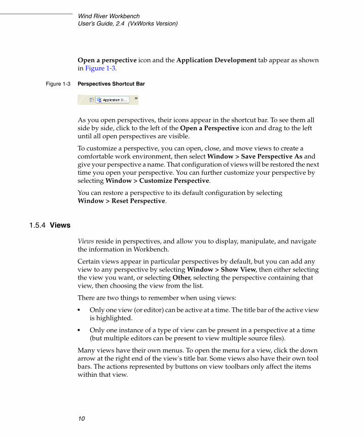
Open a perspective icon and the Application Development tab appear as shown in Figure 1-3.
As you open perspectives, their icons appear in the shortcut bar. To see them all side by side, click to the left of the Open a Perspective icon and drag to the left until all open perspectives are visible.
To customize a perspective, you can open, close, and move views to create a comfortable work environment, then select Window > Save Perspective As and give your perspective a name. That configuration of views will be restored the next time you open your perspective. You can further customize your perspective by selecting Window > Customize Perspective.
You can restore a perspective to its default configuration by selecting Window > Reset Perspective.
1.5.4 Views
Views reside in perspectives, and allow you to display, manipulate, and navigate the information in Workbench.
Certain views appear in particular perspectives by default, but you can add any view to any perspective by selecting Window > Show View, then either selecting the view you want, or selecting Other, selecting the perspective containing that view, then choosing the view from the list.
There are two things to remember when using views:
■ Only one view (or editor) can be active at a time. The title bar of the active view is highlighted.
■ Only one instance of a type of view can be present in a perspective at a time (but multiple editors can be present to view multiple source files).
Many views have their own menus. To open the menu for a view, click the down arrow at the right end of the view's title bar. Some views also have their own tool bars. The actions represented by buttons on view toolbars only affect the items within that view.
Figure 1-3 Perspectives Shortcut Bar

1 Overview1.5 Basic Eclipse Concepts
11
1Moving and Maximizing Views
Move a view by clicking either its title bar or its tab in a stacked notebook, and dragging it to a new location.
There are several ways to relocate a view:
■ Drag the view to the edge of another view and drop it. The area is then split, and both views are tiled in the same area. The cursor changes to an appropriate directional arrow as you approach the edge of a view.
■ Drag the view to the title bar of an existing view and drop it. The view will be added to a stacked notebook with tabs. When you drag the view to stack it, the cursor changes to an icon of a set of stacked folders.
■ If you drag a view over a tab in an existing view, the view will be stacked in that notebook with its tab at the left of the existing view. You can also drag an existing tab to the right of another tab to arrange tabs to your liking.
To quickly maximize a view to fill the entire perspective area, double-click its title bar. Double-click the title bar again to restore it.
1.5.5 Editors
An editor is a special type of view used to edit files. You can associate different editors with different types of files such as C, C++, Ada, Assembler, and Makefiles. When you open a file, the associated editor opens in the perspective’s editor area.
Any number of editors can be open at once, but only one can be active at a time. By default, editors are stacked in the editor area, but you can tile them in order to view source files simultaneously (see 15. Navigating and Editing for more information about Editors).
Tabs in the editor area indicate the names of files that are currently open for editing. An asterisk (*) indicates that an editor contains unsaved changes.
1.5.6 Projects
Workbench uses projects as logical containers and as building blocks that can be linked together to create a software system. The Project Navigator lets you visually organize projects into structures that reflect their inner dependencies, and therefore the order in which they are compiled and linked.

Wind River WorkbenchUser’s Guide, 2.4 (VxWorks Version)
12
1.6 Accessing Additional Interface Information
For more information about the Workbench interface, press F1 (or CTRL+F1 on Linux, or the Help button on Solaris) to open a dialog (called an infopop) containing a brief description of the current view. At the bottom of many infopops, you will see links to sections of Workbench documentation with more information on the same topic. You can also access the help system by selecting Help > Help Contents > Wind River Documentation.
For more information on Eclipse functionality, see the Eclipse Workbench User Guide under Help > Help Contents > Wind River Partner Documentation > Eclipse Platform Documentation, as well as the Eclipse web site at www.eclipse.org.

13
2Wind River Workbench
Tutorials
2.1 Introduction 13
2.2 Starting Wind River Workbench 14
2.3 Tutorial: Creating a Project and Running a Program 15
2.4 Tutorial: Editing and Debugging Source Files 21
2.5 Tutorial: Using the Editor’s Code Development Features 23
2.6 Tutorial: Tracking Items of Interest in Your Files 25
2.1 Introduction
This chapter provides tutorials designed to introduce you to Wind River Workbench and to familiarize you with its views and development concepts. The VxWorks Simulator is used to execute the sample programs, and no special hardware or system setup is required.
In the course of these tutorials, you will:
■ Create a project.■ Import source files.■ Build a project.■ Connect to a simulator.■ Set breakpoints.■ Step through code.

Wind River WorkbenchUser’s Guide, 2.4
14
■ Set a Watch variable.■ Run code.■ Edit source files.■ Track build errors. ■ Compare file history.■ Debug a project.■ Rebuild and rerun your code.
These tutorials assume a basic understanding of embedded projects and debugging concepts. They also assume that you have the Workbench software (with VxWorks support) installed correctly on your host, and that the software is installed in the default location and with the default settings.
For definitions of unfamiliar terminology, see B. Glossary.
2.2 Starting Wind River Workbench
1. Before you can run the tutorials, you must start Workbench.
On Windows:
Start > Programs > Wind River > Wind River Workbench 2.4 > Wind River Workbench 2.4
On Linux and Solaris:
Open a terminal window, then navigate to your Workbench installation directory. From the command line, type:
./startWorkbench.sh
2. When you start Workbench for the first time, Workbench creates a new registry database1. A dialog appears telling you how to migrate your registry settings from a previous registry to the new one2.
3. Click OK. The Wind River Workbench welcome screen appears.
4. Select the Start arrow to open a second welcome screen containing links to useful destinations, including the Workbench window itself.
1. A new database will also be created in /tmp if the default database is not accessible. 2. If you did not have a previous version of Workbench installed and therefore do not
have registry settings to migrate over, you can safely ignore this dialog.

2 Wind River Workbench Tutorials2.3 Tutorial: Creating a Project and Running a Program
15
2
5. To follow these tutorials, select the Workbench arrow. Workbench opens and displays the Application Development perspective.
2.3 Tutorial: Creating a Project and Running a Program
This tutorial uses the ball sample program, written in C. This program implements a set of balls bouncing in a two-dimensional grid. As the balls bounce, they collide with each other and with the walls. You see the balls move by setting a breakpoint with the property Continue on break at the outer move loop, and watching a global grid array variable in the Memory window.
First, you will create a new project in your workspace, then you will import the ball source files into it from their directory in the Workbench installation.
2.3.1 Before You Begin
Workbench preserves its configuration when you close it, so that at next launch you can resume where you left off in your development.
If you experimented with opening perspectives and moving views before starting this tutorial, switch back to the Application Development perspective by clicking its icon in the upper right corner of the Workbench window. If its icon is not visible, drag the shortcut bar to the left (your cursor will turn to a double-headed arrow) or click the double-right arrows (a dropdown list will open).
To reset the perspective and its views to their default settings, select Window > Reset Perspective.
2.3.2 Creating a Project
1. Select File > New > VxWorks Downloadable Kernel Module Project. The Project dialog appears.

Wind River WorkbenchUser’s Guide, 2.4
16
2. Enter ball in the Project Name field, then click Next. If this is your first Workbench project, skip to step 5.
3. If you have previously created any projects before starting this tutorial, the Project Structure dialog appears. Here you can choose to make your new project a subproject of an existing one, or to make an existing project a subproject of your new one. Click Next.
4. If you have any existing projects, the Build Defaults dialog appears. Here you can choose whether your project should use the build defaults from an existing project of the same type, or from the default Workbench template. Click Next.
5. The Build Support dialog appears. Click Next to accept the default settings.
6. The Build Specs screen appears. Click Deselect All, then select the check box next to the VxWorks simulator build spec for your platform and compiler (you can select more than one if you want). Click Next.
■ On Windows, select SIMNTdiab or SIMNTgnu■ On Linux, select SIMLINUXdiab or SIMLINUXgnu■ On Solaris, select SIMSPARCSOLARISdiab or
SIMSPARCSOLARISgnu
7. The Build Target screen appears. By default the build target name is the same as the project name, but you can customize it if you prefer. Click Next.
8. The Static Analysis screen appears. Leave these options checked for now. Click Finish to create the project files. The new ball project appears in the Project Navigator.
2.3.3 Importing Source Files Into Your Project
Next, import the ball sample project files.
1. Right-click the ball project folder, then select Import. The Import wizard appears.
2. Select File System and click Next. The File System page of the Import wizard appears.
3. Click the Browse button next to the From directory field. The Import from directory page appears.
4. Navigate to the installDir\workbench-2.4\samples directory. Select ball, then click OK. The File system page reappears, with the ball folder in the left pane and the files in that folder in the right pane.

2 Wind River Workbench Tutorials2.3 Tutorial: Creating a Project and Running a Program
17
2
5. Select the check box next to ball. This automatically selects all the files in the right pane. Because you are importing into the ball project, ball appears in the Into folder field. Click Finish.
6. To see the contents of the ball project folder, click the plus next to it in the Project Navigator. You will see the project files in black, and the build targets in blue. Any files that appear in gray are read-only.
2.3.4 Building Your Project
1. Build the ball project by right-clicking the ball folder in the Project Navigator and selecting Build Project from the context menu.
2. The first time you build a project, a dialog appears asking if you want Workbench to generate include paths (for more information about include paths, see 16.8.1 The Generate Include Search-Paths Wizard, p.192). You do not need to do this for the tutorial, so click Continue.
3. Build output displays in the Build Console tab at the bottom of the screen, and the output file ball.out appears in a subdirectory of ball called ball.out (SIMNTdiab_DEBUG).
2.3.5 Creating a Connection Definition to the VxWorks simulator
You create and manage connections to a target, including the VxWorks simulator, using the Target Manager.
1. To create a new target connection definition, click the Create a New Target Connection icon on the Target Manager toolbar, or right-click in the Target Manager and select New > Connection.
NOTE: The string SIMNTdiab_DEBUG reflects the active build spec, and the fact that debug mode flags are turned on by default. If you selected a different build spec, or turned off debug mode flags, the string will be different.
NOTE: If you installed VxWorks support when you installed Workbench, a VxWorks simulator connection definition named vxsim0 automatically appears below default(localhost).
This is a valid connection definition, but to understand how to manually create new target connections, continue with this tutorial.

Wind River WorkbenchUser’s Guide, 2.4
18
2. In the New Connection wizard, select Wind River VxWorks Simulator Connection, then click Next.
3. Continue clicking Next to accept all of the default configuration settings, then click Finish to create your connection definition. Because the Immediately connect to target if possible box is selected by default, Workbench attempts to connect to the simulator.
Workbench displays [connecting......], then [connected] once the connection is made. A VxWorks simulator window opens3, and the connection appears under default(localhost), with the type of target displayed under the connection.
You are now ready to run the sample program.
2.3.6 Downloading the Program and Attaching the Debugger
1. In the Project Navigator, right-click the build target ball.out, then select Debug Kernel Task. The Debug launch configuration dialog appears, with ball.out already filled in as part of the Name of the launch.
2. Type main in the Entry Point field (or select it from the drop-down list), then click Debug.
3. Several events now occur: Workbench automatically switches to the Device Debug perspective, runs the ball program on the simulator, attaches the debugger, executes the program up to main( ), and then breaks.
For more information about using the other tabs and fields in the launch configuration dialog, see 23. Launching Programs and Wind River Workbench User Interface Reference: Launch Configuration Dialog.
2.3.7 Setting Up the Device Debug Perspective
As with the Application Development perspective, the views in the Device Debug perspective can be repositioned to suit your needs.
To set up the Device Debug perspective to match this tutorial:
1. The action of the ball program is viewed in the Memory view, so select Window > Show View > Memory.
3. You do not need the VxWorks simulator window for this tutorial, so minimize it if you wish, but do not close it. For more information, see Wind River VxWorks Simulator User’s Guide.

2 Wind River Workbench Tutorials2.3 Tutorial: Creating a Project and Running a Program
19
2
The Memory view appears in the lower-right corner of the Workbench window, in the tabbed notebook with the Local Variables and Watch views.
2. Click on the title bar of the Memory view and drag it to the left, over the tabbed notebook containing the Tasks view and the Build Console. Wait for an icon of a set of stacked folders to appear at the cursor, then drop the view.
3. Right-click in the Memory view and select Display > Items size - 8 bytes.
4. Resize the Memory view so you see at least 10 rows (place the cursor over the top border of the view, and when it becomes a double-headed arrow, click and drag upwards).
5. Resize the view horizontally so you see one column in the Address pane, two columns in the Binary pane (the central section of the Memory view) and one column in the Text pane (the right-hand section of the view). The view should look similar to Figure 2-1.
6. In the Watch view, click the Name column, then type grid and press ENTER. The memory address of the grid global variable appears in the value column.
Figure 2-1 Resizing the Memory View

Wind River WorkbenchUser’s Guide, 2.4
20
7. Type the memory address of the grid global variable into the Memory view address bar and press ENTER.
8. To initialize the program, click the Step Over icon in the Debug view twice so the Memory view displays an empty box. If necessary, resize the Memory view horizontally or vertically to frame the box correctly, as shown in Figure 2-2.
As the program runs, characters representing different types of balls (two zeros, two @ signs, and two asterisks) appear in this empty box, bounce around, and collide with each other and with the walls.
2.3.8 Setting and Running to a Breakpoint.
1. In the Project Navigator, double-click main.c to open it in the Editor. Scroll past the three initialization for loops and set a breakpoint at the while statement by double-clicking in the vertical ruler to the left of it.
A blue dot appears in the vertical ruler, and the Breakpoints view displays the module and line number of the breakpoint.
2. With the breakpoint set, run to it by clicking the Resume button in the Debug view. Workbench stops when it hits the breakpoint.
3. Examine the Memory view. You should see the six characters of the sample program (representing balls) in the box. Click Resume again; colored
NOTE: If the box does not appear, make sure the address you entered in the Memory window is that of the grid global variable.
Figure 2-2 Initializing the ball Program

2 Wind River Workbench Tutorials2.4 Tutorial: Editing and Debugging Source Files
21
2
highlights indicate changes in ball position since the Memory view was last refreshed.
2.3.9 Modifying the Breakpoint
Next, change the behavior of the breakpoint so that at each break, the display will refresh (to show the bouncing balls) without stopping execution.
1. Right-click the breakpoint in the vertical ruler and select Breakpoint Properties from the context menu (or right-click the breakpoint in the Breakpoints view and select Properties). The Line Breakpoint Properties dialog appears.
2. Select the checkbox next to Continue on Break, change the Continue Delay to 50, then click OK.
3. Now click the Resume button and watch the balls bounce in the Memory window.
4. To stop the program, open the Breakpoint Properties dialog again, clear Continue on Break, then click OK. The balls may bounce once more after you click OK, but they will stop.
2.4 Tutorial: Editing and Debugging Source Files
This tutorial demonstrates how Workbench can help you with some of the most basic activities in development: editing code, building your project and noting where the build fails, and tracking and fixing errors.
Wind River WorkbenchUser’s Guide, 2.4
22
2.4.1 Before You Begin
To set up Workbench for this tutorial, switch back to the default Application Development perspective as described in 2.3.1 Before You Begin, p.15.
2.4.2 Introducing an Error into the Source Code
Because the ball sample program is shipped without errors, you must introduce one into the sources in order to view a failed build.
1. In the Project Navigator, double-click main.c to open it in the Editor.
2. Select main( ) in the Outline view. The Editor switches focus to display it.
3. Delete the semicolon (;) after the call to gridInit( ) so that it reads as follows:
gridInit()
4. Right-click in the Editor and select Save to save the file.
5. Click the X on the tab (at the top of the view) to close the main.c file.
2.4.3 Tracking Down a Build Failure
1. Build the ball project by right-clicking the ball folder in the Project Navigator and selecting Build Project from the context menu. Build output appears in the Build Console tab at the bottom of the screen.
2. When the build encounters the error you created in the main.c file, the build fails. Workbench displays a red icon containing a white X in several places:
■ In the Build Console, which comes to the foreground and displays information about the error, including the general location where the problem is suspected to be.
■ In the Project Navigator, which displays red error markers to alert you that the build failure was in the ball project, and that main.c is the file containing the error.
■ In the Problems view, which displays a description of the error, including the filename, folder, and line number.
NOTE: The status bar at the bottom of the Workbench window displays the line number and column (61:16) where your cursor is located in the Editor.

2 Wind River Workbench Tutorials2.5 Tutorial: Using the Editor’s Code Development Features
23
2
3. Double-clicking the red icon in any of these locations opens the main.c file in the Editor, with the focus at (or near) the line suspected of containing the error.
4. Replace the semicolon after gridInit.
5. Save and close the file.
2.4.4 Rebuilding the Project
This time, right-click the ball folder at the top of the project tree and select Rebuild Project. The project compiles with no errors.
2.5 Tutorial: Using the Editor’s Code Development Features
The Wind River Workbench editor provides code completion, parameter hints, and bracket matching that can help you develop your code.
2.5.1 Using Code Completion to Add Symbols to Your File
Code completion automatically suggests methods, properties and events as you enter code.
To use code completion, begin typing in the Editor. Right-click in the Editor and select Source > Content Assist. You can also use CTRL+SPACE to display a pop-up list containing valid choices based on the letters you have typed so far.
For example, in ball’s main.c:
1. Position your cursor inside the function main( ) to the right of the first { character and press ENTER. Note that the cursor automatically indents beneath the brace.
2. Begin typing grid and invoke code completion: g, r, CTRL+SPACE.
NOTE: You can change indentation, brace style, and other code formatting options by selecting Window > Preferences > Workbench > Editors > Wind River > Workbench Editor > C/C++ Code Formatter.

Wind River WorkbenchUser’s Guide, 2.4
24
A dialog appears with suggestions, and as you continue to type the i and the d, your choices narrow:
Select gridAddBall( ) and press ENTER to add the function to the file.
2.5.2 Using Parameter Hints
Parameter hints describe what data types a function accepts. When you add a function using code completion, or when you enter a function name and an open parenthesis, the Workbench Editor automatically displays any available parameter hints.

2 Wind River Workbench Tutorials2.6 Tutorial: Tracking Items of Interest in Your Files
25
2
You can also request parameter hints as you enter your code by right-clicking in the Editor and selecting Source > Parameter Hints, or by using the CTRL+SHIFT+SPACE keyboard shortcut.
2.5.3 Using Bracket Matching to Clarify Syntax
Bracket matching helps you read and troubleshoot complex syntax by highlighting related parentheses, square brackets, and braces.
If you position your cursor before an open bracket or after a closing bracket, a rectangle will enclose the corresponding bracket to make it easier to find. You can jump between the opening and closing brackets by pressing CTRL+SHIFT+P. Bracket matching operates on the following characters:
( ), [ ], { }, " ", /* */, < > (C/C++ only)
2.6 Tutorial: Tracking Items of Interest in Your Files
Adding a bookmark to a source file is similar to placing a bookmark in a book: it allows you to find an item you are interested in at a later time by looking in the Bookmarks view. Open the Bookmarks view by selecting Window > Show View > Bookmarks.

Wind River WorkbenchUser’s Guide, 2.4
26
You can create a bookmark on a particular line of code within a file, or you can bookmark the file itself.
2.6.1 Creating a Bookmark on a Source Line in a File
1. To create a bookmark on a line of code in your file, right-click in the Editor gutter to the left of the item you want to keep track of, then select Add Bookmark.
2. In the Add Bookmark dialog, enter a meaningful comment to help you identify it later, then click OK. A small bookmark icon appears in the Editor gutter, and a marker, or annotation, appears in the overview ruler at the right edge of the Editor showing your bookmark relative to its position in the file. An entry also appears in the Bookmarks view.
Hovering over the bookmark icon shows you the text you entered, and clicking the annotation on the right will return the Editor’s focus to this position if you scroll to a different line in the file.
2.6.2 Creating a Bookmark for an Entire File
1. To create a bookmark for a file, right-click it in the Project Navigator and select Add Bookmark.
2. In the Add Bookmark dialog, enter a meaningful comment to help you identify it later, then click OK.
3. The file will not look any different in the Project Navigator, but the comment you typed, the filename, and the folder appear in the Bookmarks view.
2.6.3 Locating and Viewing Your Bookmarks
1. To see the bookmarks in all your projects, open the Bookmarks view by selecting Window > Show View > Bookmarks.
2. To open the file that contains a particular bookmark, double-click the bookmark (or right-click it and select Go To). The file opens in the Editor with the bookmark location highlighted.
This chapter has been a brief introduction to basic operations with perspectives, views, and editors, and simple debugging capabilities. The rest of this guide

2 Wind River Workbench Tutorials2.6 Tutorial: Tracking Items of Interest in Your Files
27
2
provides more in depth information about these and other features of Wind River Workbench.

Wind River WorkbenchUser’s Guide, 2.4
28

29
3Setting Up Your Hardware
3.1 Introduction 29
3.2 Configuring Your Cross-Development System 33
3.3 Setting Up a Boot Mechanism 41
3.4 Booting VxWorks 43
3.5 Configuring Host-Target Communication for Workbench 54
3.6 Troubleshooting VxWorks Problems 60
3.1 Introduction
This chapter explains how to configure your host and target, including how to download a VxWorks image and boot your target.
For a discussion of common configuration and setup problems and tips for how to solve them, see 26.5 Troubleshooting VxWorks Configuration Problems, p.341. For definitions of terminology that may be unfamiliar to you, see B. Glossary.
You do not need much of this chapter if all you want to do is connect to a target that is already set up on your network. If this is the case, read 3.2 Configuring Your Cross-Development System, p.33 and then proceed with 3.4 Booting VxWorks, p.43.

Wind River WorkbenchUser’s Guide, 2.4 (VxWorks Version)
30
3.1.1 Overview of Host and Target Configuration Tasks
Host Configuration Tasks
You will need to complete these configuration tasks once per host:
■ Install Wind River Workbench.
■ Configure TCP/IP for your host.
■ Configure a method for transferring a VxWorks image to your target, such as FTP on Windows and Linux or rsh on Solaris.
Target Configuration Tasks
You will need to complete these configuration tasks once for each new target:
■ Install the VxWorks boot loader for your target (see the Wind River Workbench On-Chip Debugging Guide for details).
■ Set up one or more physical connections between your target and host.
■ Define a Workbench target server to connect to the new target.
Normal Operation
You will need to repeat these tasks each time you want to re-initialize your target during development:
■ Boot VxWorks on the target. VxWorks includes a target agent, the interface between VxWorks and all other Wind River Workbench tools, by default.
■ Launch or restart a Workbench target server on the host.
3.1.2 Understanding Target Servers and Target Agents
Wind River Workbench host tools such as shells and debuggers communicate with the target system through a target server. A target server can be configured with a
NOTE: Paths to Workbench directories and files are prefixed by installDir in this guide. Substitute the actual path to your Workbench installation directory.

3 Setting Up Your Hardware3.1 Introduction
31
3
variety of back ends, which provide for various modes of communication with the target agent. On the target side, VxWorks can be configured and built with a variety of target agent communication interfaces.
Your choice of target server back end and target agent communication interface is based on the mode of communication that you establish between the host and target (network, serial, JTAG, and so on). The target server must be configured with a back end that matches the target agent interface with which VxWorks has been configured and built. See Figure 3-1 for a detailed diagram of host-target communications.
Figure 3-1 Wind River Workbench Host-Target Communication
Shell DebuggerOther
Browser Tools
Non-WDBAgent
VxWorks
WTX PROTOCOL
AGENTS
WDB TARGET AGENTCOMMUNICATIONINTERFACES
TARGET SERVERBACK ENDS
HOST
TARGET (board or simulator)
Target Server
SerialComm
Interface
NetworkComm
Interface
WDBSerial
Non-WDBBack End
WDBTargetAgent
PipeComm
Interface
WDBPipe
WDBRPC

Wind River WorkbenchUser’s Guide, 2.4 (VxWorks Version)
32
Target Agent Modes
All of the standard target server back ends included with Workbench connect to the target through the target agent. Thus, in order to understand the features of each back end, you must understand the modes in which the target agent can execute. These modes are called user mode, system mode, and dual mode.
■ In user mode, the agent runs as a VxWorks task. Debugging is performed on a per-task basis: you can isolate the task or tasks of interest without affecting the rest of the target system.
■ In system mode, the agent runs externally from VxWorks, almost like a ROM monitor. This allows you to debug an application as if it and VxWorks were a single thread of execution. In this mode, when the target run-time encounters a breakpoint, VxWorks and the application are stopped and interrupts are locked. One of the biggest advantages of this mode is that you can single-step through ISRs; on the other hand, it is more difficult to manipulate individual tasks. Another drawback is that this mode is more intrusive; it adds significant interrupt latency to the system, because the agent runs with interrupts locked when it takes control (for example, after a breakpoint).
■ In dual mode, two agents are configured into the run-time simultaneously: a user-mode agent, and a system-mode agent. Only one of these agents is active at a time; switching between the two can be controlled from either the Workbench debugger (see 25.5 Using Debug Modes, p.313) or the host shell (see Wind River Workbench Command Line User’s Guide: Using the Host Shell).
In order to support a system-mode or dual-mode agent, the target communication path must work in polled mode (because the external agent needs to communicate to the host even when the system is suspended). Thus, the choice of communication path can affect what debugging modes are available.
Communication Paths
The most common VxWorks communication path—both for server-agent communications during development, and for applications—is TCP/IP networking over Ethernet. That connection method provides a very high bandwidth, as well as all the advantages of a network connection.
Nevertheless, there are situations where you may wish to use a non-network connection, such as a serial line or a ROM-emulator connection. For example, if you have a memory-constrained application that does not require networking, you may wish to remove the VxWorks network code from the target system during
3 Setting Up Your Hardware3.2 Configuring Your Cross-Development System
33
3
development. Also, if you wish to perform system-mode debugging, you need a communication path that can work in polled mode.
Note that the target server back end connection is not always the same as the connection used to load the VxWorks image into target memory. For example, you can boot VxWorks over Ethernet, but use a serial line connection to exploit a polled-mode serial driver for system-mode debugging.
You can also use a non-default method of getting the run-time system itself into your target board. For example, you might burn your VxWorks run-time system directly into target ROM, as described in the VxWorks Programmer’s Guide: Configuration and Build. Alternatively, you can use a ROM emulator to quickly download new VxWorks images to the target’s ROM sockets. Another possibility is to boot from a disk locally attached to the target; see the VxWorks Programmer’s Guide: Local File Systems. Individual Board Support Packages (BSPs) may provide other alternatives, such as flash memory; see the reference information for your BSP.
For a tutorial that explains how to use Wind River ICE or Wind River Probe to load the run-time system onto your target, see Wind River ICE for Wind River Workbench Hardware Reference or Wind River Probe for Wind River Workbench Hardware Reference.
3.2 Configuring Your Cross-Development System
Before VxWorks can boot an executable image obtained from the host, the network software on the host must be correctly configured (see Configuring Host Software, p.33), your target must be connected and powered up (see Verifying Serial Setup and Power, p.37), and the boot loader must be loaded onto your target.
3.2.1 Configuring Host Software
For your target to communicate with the Workbench host tools, you need to have a Wind River registry, TCP/IP, and FTP running on your host.
The following sections describe these procedures in more detail.

Wind River WorkbenchUser’s Guide, 2.4 (VxWorks Version)
34
Establishing the VxWorks Target Name and IP Address
You can configure the server that provides Domain Name Service (DNS) so that your computer uses that server to translate system names to network IP addresses. Consult your operating system documentation on how to configure your system to take advantage of DNS.
If you do not have a domain name server at your site, you can specify how to map machine names to IP addresses in a file called hosts (C:\Windows\system32\drivers\etc\hosts on Windows, /etc/hosts on Linux and Solaris) which records the names and IP network addresses of systems accessible on the network from the local system (otherwise, you would have to identify targets by IP address).
Each line consists of an IP address and the name (or names) of the system at that address.
For example, suppose your host system is called mars and has Internet address 90.0.0.1, and you want to name your VxWorks target phobos and assign it address 90.0.0.50. The hosts file must then contain the following lines:
90.0.0.1 mars90.0.0.50 phobos
This configuration is represented in Figure 3-7.
Configuring FTP on Windows
To use the default VxWorks configuration and boot VxWorks over the network, you must have an FTP server running on the host where the VxWorks system image is stored, and the FTP server must have a user ID and password defined that your VxWorks target can use to identify itself.
Workbench includes an FTP server application, WFTPD. Start this FTP server from the Windows Start menu by selecting Programs > Wind River > VxWorks 6.0 > FTP Server.
Before an FTP client can connect to WFTPD, you must complete the following steps:
1. Open the WFTPD window and select Security > Users/rights (Figure 3-2).
! CAUTION: If you are in a networked environment, do not pick arbitrary IP addresses for your host and target as they could be assigned to someone else. Contact with your system administrator for available IP addresses.

3 Setting Up Your Hardware3.2 Configuring Your Cross-Development System
35
3
2. WFTPD displays the User / Rights Security Dialog box shown in Figure 3-3. Click the New User button; another dialog box (also shown in Figure 3-3) appears where you can enter whatever arbitrary name you wish as the user ID for the VxWorks boot ROM. Be sure to use this same name when you assign the user (u) VxWorks boot parameter described in 3.4.4 Description of Boot Parameters, p.47.
3. After you specify the user name and click OK, WFTPD displays a third dialog box where you can specify a password (Figure 3-4). Use any memorable arbitrary string, and be sure to use this same string when you assign the ftp password (pw) VxWorks boot parameter described in 3.4.4 Description of Boot Parameters, p.47.
Because the password does not display as you type it, you must type it twice to be sure the correct password is recorded.
Figure 3-2 WFTPD Security Menu
Figure 3-3 Adding a New User for WFTPD

Wind River WorkbenchUser’s Guide, 2.4 (VxWorks Version)
36
4. After defining the new user ID and password, be sure to fill in the Home Directory text box (Figure 3-5). The VxWorks boot loader does not require this information, but WFTPD refuses to connect to a client unless you specify a home directory. Any directory will be fine, as long as you permit sufficient disk access for the VxWorks boot loader to read the boot image on your Windows disk.
5. Close the User / Rights Security Dialog box by clicking Done.
6. To enable logging of FTP activities, select Logging > Log Options and select the types of activities you want to log. The log file will be saved in the home directory you specified above.
When you have finished configuring your FTP settings, leave the FTP server running. It must be running on your host when your target tries to access the vxWorks image.
Figure 3-4 WFTPD Password Dialog Box
NOTE: Your password must not be an empty string.
Figure 3-5 WFTPD Home Directory
NOTE: You can run the FTP server as a restricted user, but you cannot add new users and passwords if you are a restricted user. A non-restricted user must add the new users and passwords for you.

3 Setting Up Your Hardware3.2 Configuring Your Cross-Development System
37
3
Becoming Familiar with the Wind River Registry
The Wind River target server registry is a service that keeps track of running target servers. The registry must be running for Workbench tools to communicate with VxWorks targets. Workbench development tools communicate with the target server using TCP/IP, which in turn communicates with the VxWorks target over the selected communication method (such as serial, Ethernet, or TMD). The registry is always required, independent of the link between the target server and the VxWorks target.
Workbench starts the default registry automatically, though if required you can connect to a registry running on a networked host instead (see 19.6 Connect to the Target, p.242 for details about connecting to other registries).
You can tell that the Wind River registry is running on your host system if:
■ The registry icon is displayed in the Windows system tray.
■ Running the ps command on Linux or Solaris shows wtxregd.ex in the jobs list.
To shut down the registry:
■ Right-click the registry icon in the Windows system tray and select Shutdown.
■ Type killall wtxregd.ex in a Solaris terminal window.
■ Type wrenv.linux -p workbench-2.3 wtxregd stop in a Linux terminal window.
For detailed information about the operation of the Workbench registry, and its command options, see the online reference entry for wtxregd (Help > Help Contents > Wind River Documentation > References > Wind River Workbench Host Tools API Reference).
3.2.2 Verifying Serial Setup and Power
Hardware settings are specific to your target and host. This section describes in general terms the types of hardware connections you must make to follow the instructions in this book, but be aware that you may need to make adjustments to accommodate your specific cross-development system.
Configuring your target hardware may involve the following tasks:
■ Protecting your equipment against electrostatic discharge.
■ Setting switches and jumpers on the target CPU board.

Wind River WorkbenchUser’s Guide, 2.4 (VxWorks Version)
38
■ Connecting a serial cable and/or an Ethernet cable, if the target supports networking.
■ Connecting a power supply.
Perform the following general procedures as appropriate for your particular target hardware. For details, see the target reference for your BSP (such as installDir/vxworks-6.1/target/config/bspname/target.ref) and the documentation provided by your target system’s manufacturer.
Protecting Equipment from Electrostatic Discharge (ESD)
You should always discharge the static electricity that may have collected on your body before you touch integrated circuit boards, including targets and network interface cards (NICs).
Electrostatic discharge precautions include:
■ touching the metal enclosure of a plugged-in piece of electrical equipment (such as a PC or a power supply in a metal case)
■ placing your equipment on, or standing on, an anti-static mat
■ wearing an ESD wrist strap
Setting Board Switches and Jumpers
Many CPU and Ethernet controller boards still have configuration options that are selected by hardware jumpers, although this is less common than in the past. These jumpers must be set correctly before VxWorks can boot successfully.
You can determine the correct jumper configuration for your target CPU from the information provided in the target information reference for your BSP, and in the target system’s documentation.
NOTE: If you are using a Wind River ICE or Wind River Probe emulator to connect to your target, see the Wind River ICE for Wind River Workbench Hardware Reference or Wind River Probe for Wind River Workbench Hardware Reference for information about how to connect to your target.
! CAUTION: Failure to take proper ESD precautions can degrade target hardware over time, leading to intermittent errors or hardware failure.
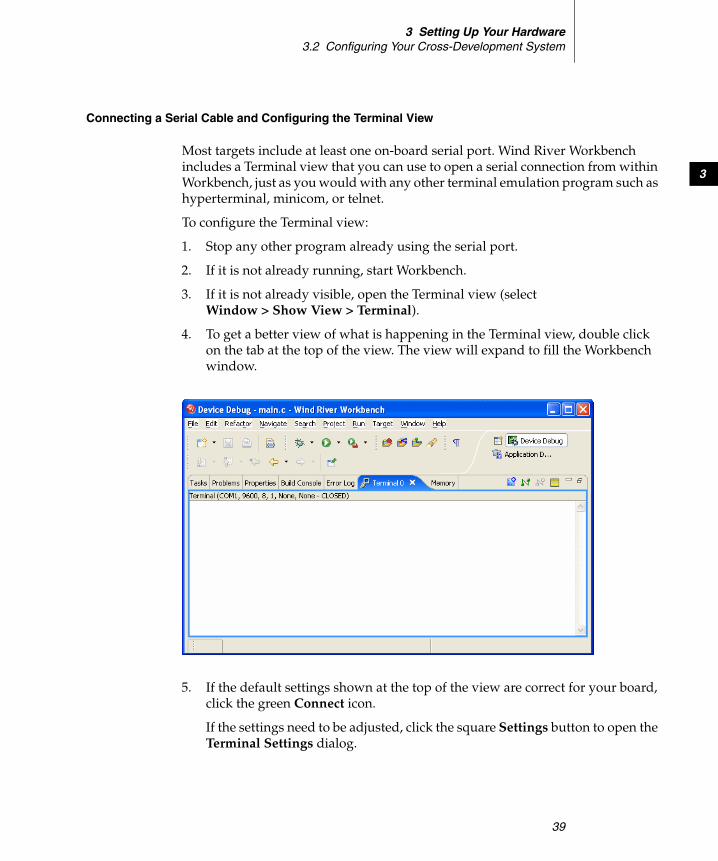
3 Setting Up Your Hardware3.2 Configuring Your Cross-Development System
39
3
Connecting a Serial Cable and Configuring the Terminal View
Most targets include at least one on-board serial port. Wind River Workbench includes a Terminal view that you can use to open a serial connection from within Workbench, just as you would with any other terminal emulation program such as hyperterminal, minicom, or telnet.
To configure the Terminal view:
1. Stop any other program already using the serial port.
2. If it is not already running, start Workbench.
3. If it is not already visible, open the Terminal view (select Window > Show View > Terminal).
4. To get a better view of what is happening in the Terminal view, double click on the tab at the top of the view. The view will expand to fill the Workbench window.
5. If the default settings shown at the top of the view are correct for your board, click the green Connect icon.
If the settings need to be adjusted, click the square Settings button to open the Terminal Settings dialog.

Wind River WorkbenchUser’s Guide, 2.4 (VxWorks Version)
40
6. Configure the terminal settings as appropriate for your system:
Connection TypeSelect Serial.
On Linux, if you are not running your Linux host as a root user, make sure the permissions are set correctly for you to access the serial port (if you do not have permissions set correctly, only the NET option is available under Connection Type).
To set them, issue one of the following commands (depending on which port you plan to use):
$ chmod 666 /dev/ttyS0$ chmod 666 /dev/ttyS1
PortSet the port to the port you are using. Defaults are COM1 on Windows, ttyS0 on Linux, and /dev/cua/a on Solaris.
Baud RateConfigure the baud rate to match the speed of your connection.
Data BitsDefault on all platforms is 8.
Stop BitsDefault on all platforms is 1.
ParityDefault on all platforms is None.

3 Setting Up Your Hardware3.3 Setting Up a Boot Mechanism
41
3
Flow InDefault on all platforms is None.
Flow OutDefault on all platforms is None.
7. Click OK to open a serial connection to your target.
8. To disconnect from your target, click Disconnect. To reopen the connection with the existing settings, click Connect.
After initially configuring the boot parameters and getting started with VxWorks, you may wish to configure VxWorks to boot automatically without a terminal. Refer to the target system hardware documentation for proper connection of the RS-232 signals.
Connecting a Cable for the Ethernet Connection
Always make sure you use the correct cable:
■ when connecting your board directly to your host, use a crossover cable
■ when connecting your board to a LAN, use a non-crossover cable
Connecting A Power Supply
For standalone targets, use the power supply recommended by the board manufacturer.
3.3 Setting Up a Boot Mechanism
Workbench is shipped with the following VxWorks images, compiled both with the Wind River Compiler and with the GNU compiler:
vxWorks
! CAUTION: Be sure to follow ESD precautions (see Protecting Equipment from Electrostatic Discharge (ESD), p.38) whenever working with integrated circuit boards, including targets and NICs.

Wind River WorkbenchUser’s Guide, 2.4 (VxWorks Version)
42
vxWorks_romvxWorks_romCompressvxWorks_romResident
In every case, you will need to create your own boot medium.Your board will require one of the following media:
ROM
Most boards boot from ROMs.
For cases where boot ROMs are used to boot VxWorks, install the appropriate set of boot ROMs on your target board(s). When installing boot ROMs, be careful to:
■ Install each device only in the socket indicated on the label.
■ Note the correct orientation of pin 1 for each device.
■ Use anti-static precautions whenever working with integrated circuit devices. For more information, see Protecting Equipment from Electrostatic Discharge (ESD), p.38.
Floppy Disk
Some BSPs for systems that include floppy drives use boot diskettes instead of a boot ROM. For example, Pentium systems usually boot from diskette.
Flash Memory
For boards that support flash memory, the BSP may be designed to write the boot program there. In such cases, an auxiliary program to write the boot program into flash memory is supplied by the board vendor.
For specific information on a particular booting method, see Help > Help Contents > Wind River Documentation > Guides > Operating System > VxWorks BSP Developer's Guide. Instructions for making a floppy disk for booting a Pentium target are in the target.ref file for the BSP.
You may also wish to replace a boot ROM, even if it is available, with a ROM emulator. This is particularly desirable if your target has no Ethernet capability, because the ROM emulator can be used to provide connectivity at near-Ethernet speeds. Contact Wind River for information about support for ROM emulators.

3 Setting Up Your Hardware3.4 Booting VxWorks
43
3
3.4 Booting VxWorks
Once you have configured your host software and target hardware, you are ready to boot VxWorks.
With your target connected to your host and a serial connection open in the Terminal view, click Connect (see Connecting a Serial Cable and Configuring the Terminal View, p.39).
3.4.1 Default Boot Process
When you boot VxWorks with the default boot program (from a ROM, a diskette, or another medium), you must use the VxWorks command line to provide the boot program with information that allows it to find the VxWorks image on the host and load it onto the target. The default boot program is designed for a networked target, and needs to have the correct host and target network addresses, the full path and name of the file to be booted, the user name, and so on.
Unless your target CPU has non-volatile RAM (NV-RAM), you will eventually find it useful to build a new version of the boot loader that includes all parameters required for booting a VxWorks image. In the course of developing an application, you will also build bootable applications
When you power on the target hardware (and each time you reset it), the target system executes the boot program from ROM; during the boot process, the target uses its serial port to communicate with your terminal or workstation. The boot program first displays a banner page, and then starts a seven-second countdown, visible on the screen as shown in Figure 3-6.
NOTE: If you are using a VxWorks image configured for a network connection (the default), you must have an FTP server running on the Windows host where the VxWorks system image is stored. See Configuring FTP on Windows, p.34 for more information.

Wind River WorkbenchUser’s Guide, 2.4 (VxWorks Version)
44
Unless you press any key on the keyboard within that seven-second period, the boot loader will attempt to proceed with a default configuration, and will not be able to boot the target with VxWorks.
3.4.2 Entering New Boot Parameters
To interrupt the boot process and provide the correct boot parameters, first power on (or reset) the target; then stop the boot sequence by pressing any key during the seven-second countdown.
The boot program displays the VxWorks boot prompt:
[VxWorks Boot]:
To display the current (default) boot parameters, type p at the boot prompt:
[VxWorks Boot]: p
A display similar to the following appears; the meaning of each of these parameters is described in 3.4.4 Description of Boot Parameters, p.47.
Figure 3-6 Boot Program Banner Display

3 Setting Up Your Hardware3.4 Booting VxWorks
45
3
boot device : lnunit number : 0processor number : 0host name : marsfile name : c:\temp\vxWorks1
inet on ethernet (e) : 90.0.0.50:ffffff00inet on backplane (b) :host inet (h) : 90.0.0.1gateway inet (g) :user (u) : fredftp password (pw)(blank=use rsh) :secretflags (f) : 0x0target name (tn) : phobosstartup script (s) :other (o) :
This example corresponds to the configuration shown in Figure 3-7. The p command does not actually display the lines with blank fields, although this example shows them for completeness.
To change the boot parameters, type c at the boot prompt:
[VxWorks Boot]: c
In response, the boot program prompts you for each parameter. If a particular field has the correct value already, press ENTER. To clear a field, enter a period ( . ),
1. Pre-built VxWorks images are available in installDir\vxworks-6.2\target\proj\bsp-compiler\default, but in this example the vxWorks file has been copied to c:\temp.
Figure 3-7 Boot Configuration Example
TARGET
phobos
HOST
mars
90.0.0.50:ffffff0090.0.0.1
c:\temp\vxWorks
user: fred
Ethernet
90.0.0.x subnet

Wind River WorkbenchUser’s Guide, 2.4 (VxWorks Version)
46
then press ENTER. To go back to change the previous parameter, enter a dash (-), then press ENTER. If you want to quit before completing all parameters, type CTRL+D.
Network information must be entered to match your particular cross-development system configuration. The Internet addresses must match those in the hosts file on your system (or those known to your Domain Name Server), as described in Establishing the VxWorks Target Name and IP Address, p.34.
If your target has non-volatile RAM (NV-RAM), the boot parameters are stored there and retained even if power is turned off. For each subsequent power-on or system reset, the boot program uses these stored parameters for the automatic boot configuration.
3.4.3 Boot Program Commands
The VxWorks boot program provides a limited set of commands. To see a list of available commands, type either h or ? at the boot prompt, followed by ENTER:
[VxWorks Boot]: ?
Table 3-1 describes each of the VxWorks boot commands and their arguments.
Table 3-1 VxWorks Boot Commands
Command Description
h Help command—print a list of available boot commands.
? Same as h.
@ Boot (load and execute file) using the current boot parameters.
p Print the current boot parameter values.
c Change the boot parameter values.
l Load the file using current boot parameters, but without executing.
g adrs Go to (execute at) hex address adrs.
d adrs[, n] Display n words of memory starting at hex address adrs. If n is omitted, the default is 64.

3 Setting Up Your Hardware3.4 Booting VxWorks
47
3
3.4.4 Description of Boot Parameters
Each of the boot parameters is described below, with reference to the example in 3.4.2 Entering New Boot Parameters, p.44. The letters in parentheses after some parameters indicate how to specify the parameters in the command line boot procedure described in 3.4.6 Alternate Boot Methods, p.52.
boot device The type of device to boot from. This must be one of the drivers included in the boot ROMs (for example, enp for a CMC controller). Due to limited space in the boot ROMs, only a few drivers can be included. A list of included drivers is displayed at the console (type ? or h).
m adrs Modify memory at location adrs (hex). The system prompts for modifications to memory, starting at the specified address. It prints each address, and the current 16-bit value at that address, in turn. You can respond in one of several ways:
ENTER: Do not change that address, but continue prompting at the next address.
number: Set the 16-bit contents to number.
. (dot): Do not change that address, and quit.
f adrs, nbytes, value Fill nbytes of memory, starting at adrs with value.
t adrs1, adrs2, nbytes Copy nbytes of memory, starting at adrs1, to adrs2.
s [ 0 | 1 ] Turn the CPU system controller ON (1) or OFF (0) (only on boards where the system controller can be enabled by software).
e Display a synopsis of the last occurring VxWorks exception.
v Display BSP and boot ROM version.
N Set Ethernet address.
Table 3-1 VxWorks Boot Commands (cont’d)
Command Description

Wind River WorkbenchUser’s Guide, 2.4 (VxWorks Version)
48
unit numberThe unit number of the boot device, starting at zero.
processor number A unique numerical target identifier for systems with multiple targets on a backplane. The backplane master must have its processor number set to zero. For boards not connected to a backplane, a value of zero is typically used but is not required.
host name The name of the host machine to boot from. This is the name by which the host is known to VxWorks; it need not be the name used by the host itself. (The host name is mars in the example of 3.4.2 Entering New Boot Parameters, p.44.)
file name The full pathname of the VxWorks image to be booted (c:\temp\vxWorks in the example). This pathname is also reported to the host when you start a target server, so that it can locate the host-resident image of VxWorks. The pathname is limited to a 160 byte string, including the null terminator.2
inet on ethernet (e) The Internet Protocol (IP) address of a target system Ethernet interface, as well as the subnet mask used for that interface. The address consists of the IP address, in dot decimal format, followed by a colon, followed by the mask in hex format (here, 90.0.0.50:ffffff00). For more information about working with IP addresses, see Establishing the VxWorks Target Name and IP Address, p.34.
inet on backplane (b) The Internet address of a target system with a backplane interface (blank in the example).
host inet (h) The Internet address of the host to boot from (90.0.0.1 in the example).
gateway inet (g) The Internet address of a gateway node if the host is not on the same network as the target (blank in the example).
user (u) The user ID that VxWorks uses to access the host for the purpose of boot loading the file specified by the filename boot parameter (fred in the
2. If the same pathname is not suitable for both host and target—for example, if you boot from a disk attached only to the target—you can specify the host path separately to the target server, using the -c filename option in the Advanced Target Server Options field of the New Target Server Connection dialog.

3 Setting Up Your Hardware3.4 Booting VxWorks
49
3
example); use the user name you created in Configuring FTP on Windows, p.34. That user must have permission to read the VxWorks boot-image file.
On a Windows host, the user must have FTP access to that host. On a UNIX host, the user must have FTP or rsh access. The ftp password boot parameter described below controls how the boot loader accesses the host. For rsh, the user must be granted access by adding the user ID to the host's /etc/host.equiv file, or more typically to the user's .rhosts file (~userName/.rhosts).
ftp password (pw) The user password used by the boot loader to access the host using FTP for the purpose of boot loading the file specified by the filename boot parameter. Use the password you created in Configuring FTP on Windows, p.34.
flags (f) Configuration options specified as a numeric value that is the sum of the values of selected option bits defined below. (This field is zero in the example because no special boot options were selected.)
target name (tn) The name of the target system to be added to the host table (here, phobos).
NOTE: This field is not required by the boot program, but you must supply it to boot over the network from a Windows host. Without it, the boot ROM attempts to load the run-time system image using a protocol based on the UNIX rsh utility, which is not available for Windows hosts. So an FTP password is required, but only for host access during boot loading.
0x01 = Do not enable the system controller, even if the processor number is 0. (This option is board specific; refer to your target documentation.)
0x02 = Load all VxWorks symbols, instead of just globals.0x04 = Do not auto-boot.0x08 = Auto-boot fast (short countdown).0x20 = Disable login security.0x40 = Use BOOTP to get boot parameters.0x80 = Use TFTP to get boot image.0x100 = Use proxy ARP.0x200 = Use WDB agent.0x400 = Set system to debug mode for the error detection and reporting facility
(depending on whether you are working on kernel modules or user applications, for more information see the VxWorks Kernel Programmer’s Guide: Error Detection and Reporting or the VxWorks Application Programmer’s Guide: Error Detection and Reporting).
Wind River WorkbenchUser’s Guide, 2.4 (VxWorks Version)
50
startup script (s) If the kernel shell is included in the downloaded image, this parameter allows you to pass to it the path and filename of a startup script to execute after the system boots. A startup script file can contain only the shell’s C interpreter commands. This parameter can also be used to specify process-based applications to run automatically at boot time, if VxWorks has been configured with the appropriate components. See VxWorks Application Programmer’s Guide: Applications and Processes and Target Tools.
other (o) This parameter is generally unused and available for applications (blank in the example). It can be used when booting from a local SCSI disk to specify a network interface to be included.
3.4.5 Booting With New Parameters
After entering the boot parameters, initiate booting by typing the @ command:
[VxWorks Boot]: @

3 Setting Up Your Hardware3.4 Booting VxWorks
51
3
Figure 3-8 shows a typical VxWorks boot display. The VxWorks boot program prints the boot parameters, and the downloading process begins.
The following information is displayed during the boot process:
■ The boot program first initializes its network interfaces.
■ After the system is completely loaded, the boot program displays the entry address and transfers control to the loaded VxWorks system.
■ When VxWorks starts up, it begins just as the boot ROM did, by initializing its network interfaces; the network-initialization messages appear again, sometimes accompanied by other messages about optional VxWorks facilities.
■ After this point, VxWorks is up and ready to attach to the Wind River Workbench tools.
Figure 3-8 VxWorks Booting Display

Wind River WorkbenchUser’s Guide, 2.4 (VxWorks Version)
52
■ The boot display may be useful for troubleshooting. The following hints refer to Figure 3-8. For more troubleshooting ideas, see 26.5 Troubleshooting VxWorks Configuration Problems, p.341.
– If Attaching network interface is displayed without the corresponding done, verify that the system controller is configured properly and the network interface card is properly jumpered. This error may also indicate a problem with the network driver in the newly loaded VxWorks image.
– If Loading... is displayed for more than 30-45 seconds without the size of the VxWorks image appearing, this may indicate problems with the Ethernet cable or connection, or an error in the network configuration (for example, a bad host or gateway Internet address).
– If the line Starting at is printed and there is no further indication of activity from VxWorks, this generally indicates there is a problem with the boot image.
3.4.6 Alternate Boot Methods
To boot VxWorks, you can also use the command line, take advantage of non-volatile RAM, or create new boot programs for your target.
Command Line Parameters
Instead of being prompted for each of the boot parameters, you can supply the boot program with all the parameters on a single line at the boot prompt ([VxWorks Boot]:) beginning with a dollar sign character (“$”). For example:
$ln(0,0)mars:c:\temp\vxWorks e=90.0.0.50 h=90.0.0.1 u=fred pw=…
The order of the assigned fields (those containing equal signs) is not important. Omit any assigned fields that are irrelevant. The codes for the assigned fields correspond to the letter codes shown in parentheses by the p command. For a full description of the format, see the reference entry for bootParseLib.
This method can be useful if your workstation has programmable function keys. You can program a function key with a command line appropriate to your configuration.
Non-volatile RAM (NV-RAM)
As noted previously, if your target CPU has non-volatile RAM (NV-RAM), all the values you enter in the boot parameters are retained in the NV-RAM. In this case,
3 Setting Up Your Hardware3.4 Booting VxWorks
53
3
you can let the boot program auto-boot without having a terminal program connected to the target system.
Customized Boot Programs
See the VxWorks Kernel Programmer’s Guide for instructions on creating a new boot program for your boot media, with parameters customized for your site. With this method, you no longer need to alter boot parameters before booting.
BSPs Requiring TFTP on the Host
Some Motorola boards that use Bug ROMs and place boot code in flash require the TFTP protocol on the host in order to burn a new VxWorks image into flash. Workbench ships with a version of TFTP. See your target system documentation on how to burn flash for these boards.
3.4.7 Rebooting VxWorks
When VxWorks is running, there are several ways you can reboot it. Rebooting by any of these means restarts the attached target server on the host as well:
■ Entering CTRL+X in the Terminal view (other Windows terminal emulators do not pass CTRL+X to the target, because of its standard Windows meaning.)
■ Invoking reboot( ) from the host shell.
■ Pressing the reset button on the target system.
■ Turning the target’s power off and on.
When you reboot VxWorks in any of these ways, the auto-boot sequence begins again from the countdown.
! CAUTION: Be sure to follow ESD precautions (see Protecting Equipment from Electrostatic Discharge (ESD), p.38) whenever working with integrated circuit boards, including targets and NICs.

Wind River WorkbenchUser’s Guide, 2.4 (VxWorks Version)
54
3.5 Configuring Host-Target Communication for Workbench
If you are developing applications, an Ethernet connection is the easiest to set up and use, since most VxWorks targets already use the network (for example, to boot), so no additional target set-up is required. Furthermore, a network interface is typically a board’s fastest physical communication channel.
If you need a JTAG or other emulator connection, see the Wind River ICE for Wind River Workbench Hardware Reference or the Wind River Probe for Wind River Workbench Hardware Reference for information about making emulator connections to your target.
The next few sections describe the setup of Ethernet, serial line, and TMD connections within Workbench.
3.5.1 Ethernet Connections
When VxWorks is configured and built with a network interface for the target agent (the default configuration), the target server can connect to the target agent using the default wdbrpc back end.
The target agent can receive requests over any device for which a VxWorks network interface driver is installed. The typical case is to use the device from which the target was booted; however, any device can be used by specifying its IP address to the target server.
Connecting to the Target Server
You can connect the target server to the agent by following these steps:
1. Click the Create a new target connection icon in the Target Manager toolbar.
NOTE: If you experience problems when using Workbench tools with a hardware platform with a new Ethernet driver/chipset, it is highly recommended that you use the WDB agent over a different communications link (such as serial or the JTAG Transparent Mode Driver) isolate if the driver is the source of the problem.

3 Setting Up Your Hardware3.5 Configuring Host-Target Communication for Workbench
55
3
The Connection Type dialog appears.
2. Select Wind River Target Server Connection for VxWorks then click Next. The Target Server Connection dialog appears.
NOTE: You will see both VxWorks and Linux connection types only if you have licensed both products.

Wind River WorkbenchUser’s Guide, 2.4 (VxWorks Version)
56
3. Select the wdbrpc back end, and type in the name or IP address of the target (you may specify a name only if you added it to your hosts file in Establishing the VxWorks Target Name and IP Address, p.34).
4. In the Advanced Target Server Options section, select the Verbose targetserver output.
Your command line should look like this:
tgtsvr -V -R C:/installDir/workspace -RW ipaddress
5. Click Next through the next two screens, then click Finish. Your new target server connection definition will appear in the Target Manager connection list, along with the simulator connection definition you created in 2.3.5 Creating a Connection Definition to the VxWorks simulator, p.17.

3 Setting Up Your Hardware3.5 Configuring Host-Target Communication for Workbench
57
3
The Immediately connect to target if possible box is selected by default, so if your target booted successfully in Booting With New Parameters, p.50, the Target Manager will attempt to connect to your target.
6. If everything is set up properly, you will see [connected] after the target server connection. If you have problems connecting, see Troubleshooting VxWorks Configuration Problems, p.341.
3.5.2 Serial-Line Connections
A minimal cross-development configuration is one in which the standalone target is connected to the host development system by a single serial line. For a configuration of this sort, use a combination of a boot mechanism that does not require a network and an alternative Workbench communications back end.
Workbench can operate over a raw serial connection between the host and target systems, and can operate on non-networked systems, but this type of connection is very slow and may not be practical for real-world debugging.
When you connect the host and target exclusively over serial lines, you must:
■ Configure and build a boot program to download over the serial connection, or build an image that boots directly from on-board Flash/ROM memory.
■ Reconfigure and rebuild VxWorks with a target agent configuration for a serial connection.
■ Configure and start a target server for a serial connection.
A raw serial connection has some advantages over an IP connection. The raw serial connection allows you to scale down the VxWorks system (even during development) for memory-constrained applications that do not require networking: you can remove the VxWorks network code from the target system.

Wind River WorkbenchUser’s Guide, 2.4 (VxWorks Version)
58
When working over a serial link, use the fastest possible line speed. The Workbench tools—especially the debugger—make it easy to set up system snapshots that are periodically refreshed. Refreshing such snapshots requires continuing traffic between host and target. On a serial connection, the line speed can be a bottleneck in this situation. If your Workbench tools seem unresponsive over a serial connection, try turning off periodic updates in the browser, or else closing any debugger displays you can spare.
Configuring the Target Agent For Serial Connection
To configure the target agent for a raw serial communication connection, reconfigure and rebuild VxWorks with a serial communication interface for the target agent (see the VxWorks Programmer’s Guide for details).
Configuring the Boot Program for Serial Connection
When you connect the host and target exclusively over serial lines, you must configure and build a boot program for the serial connection because the default boot configuration uses an FTP download from the host.
Testing the Connection
Be sure to use the right kind of cable to connect your host and target. Use a simple Tx/Rx/GND serial cable because the host serial port is configured not to use handshaking. Many targets require a null-modem cable; consult the target system’s documentation. Configure your host system serial port for a full-duplex (no local echo), 8-bit connection with one stop bit and no parity bit. The line speed must match whatever is configured into your target agent.
Before trying to attach the target server for the first time, test that the serial connection to the target is good. To help verify the connection, the target agent sends the following message over the serial line when it boots (with WDB_COMM_SERIAL):
WDB READY
To test the connection, attach a terminal emulator to the target-agent serial port, then reset the target (see Connecting a Serial Cable and Configuring the Terminal View, p.39). If the WDB READY message does not appear, or if it is garbled, check the configuration of the serial port you are using on your host.

3 Setting Up Your Hardware3.5 Configuring Host-Target Communication for Workbench
59
3
As a further debugging aid, you can also configure the serial-mode target agent to echo all characters it receives over the serial line. This is not the default configuration, because as a side effect it stops the boot process until a target server is attached. If you need this configuration in order to set up your host serial port, edit installDir\vxworks-6.1\target\config\comps\src\wdbSerial.c.
Look for the following lines:
#ifdef INCLUDE_WDB_TTY_TEST{int waitChar = 0;
if (WDB_TTY_ECHO)waitChar = 0333;
#ifdef INCLUDE_KERNEL/* test in polled mode if the kernel hasn't started */
if (taskIdCurrent == 0)wdbSioTest (pSioChan, SIO_MODE_POLL, waitChar);elsewdbSioTest (pSioChan, SIO_MODE_INT, waitChar);
#else /* INCLUDE_KERNEL */wdbSioTest (pSioChan, SIO_MODE_POLL, waitChar);
#endif /* INCLUDE_KERNEL */}
#endif /* INCLUDE_WDB_TTY_TEST */
In each call to wdbSioTest( ), change waitChar to 0300.
With this configuration, attach any terminal emulator on the host to the COM port connected to the target to verify the serial connection. When the serial-line settings are correct, whatever you type to the target is echoed as you type it.
Connecting to the Target Server
After successfully testing the serial connection, you can connect the target server to the agent by following steps similar to those in Connecting to the Target Server, p.54:
1. Close the serial port that you opened for testing (if you do not close the port, it will be busy when the target server tries to use it).
NOTE: This configuration change also prevents the target from completing its boot process until a target server attaches to it. Thus, it is best to change the wdbSioTest( ) calls back to the default as soon as you verify that the serial line is set up correctly.

Wind River WorkbenchUser’s Guide, 2.4 (VxWorks Version)
60
2. Click the Create a new target connection icon in the Target Manager toolbar. The Connection Type dialog appears.
3. Select Wind River Target Server Connection then click Next. The TargetServer Connection dialog appears.
4. Select the wdbserial back end, and type in the name or IP address of the target (you may specify a name only if you added it to your hosts file in Establishing the VxWorks Target Name and IP Address, p.34).
5. In the Advanced Target Server Options section, select Verbose targetserver output, then specify the communications port with -d, and also specify the line speed to match the speed configured into your target. Your command line should look like this:
tgtsvr -V -d comport -bps speed -B wdbserial ipaddress
6. Click Next through the next two screens, then click Finish. Your new target server connection definition will appear in the Target Manager connection list.
7. Select the target server definition you just created, then click the Connect icon. If everything is set up properly, you will see [connected] after the target server connection. If you have problems connecting, see Troubleshooting VxWorks Configuration Problems, p.341.
3.6 Troubleshooting VxWorks Problems
If you encountered problems booting or exercising VxWorks, there are many possible causes. Read 26.5 Troubleshooting VxWorks Configuration Problems, p.341 before contacting Wind River customer support. Often, you can locate the problem just by rechecking the installation steps and your hardware configuration.

61
PAR T II
Projects
4 Projects Overview .............................................. 63
5 VxWorks Image Projects .................................... 75
6 Boot Loader Project ........................................... 89
7 ROMFS File System Projects ............................ 93
8 VxWorks Real-time Process Projects ............... 97
9 VxWorks Shared Library Projects ..................... 105
10 VxWorks Downloadable Kernel Module Projects 113
11 VxWorks User-Defined Projects ........................ 121
12 Native Application Projects ............................... 125
13 Working in the Project Navigator ...................... 131
14 Advanced Project Scenarios ............................. 143

Wind River WorkbenchUser’s Guide, 2.4 (VxWorks Version)
62

63
4Projects Overview
4.1 Introduction 63
4.2 Workspace/Project Location 64
4.3 Creating New Projects 64
4.4 Overview of Preconfigured Project Types 66
4.5 Projects and Project Structures 70
4.1 Introduction
Workbench uses projects as logical containers and as building blocks that can be linked together to create a software system. The Project Navigator lets you, among other things, visually organize projects into structures that reflect their inner dependencies, and therefore the order in which they are compiled and linked.
Pre-configured templates for various project types allow you to create or import projects using simple wizards that need only minimal input.

Wind River WorkbenchUser’s Guide, 2.4 (VxWorks Version)
64
4.2 Workspace/Project Location
The Wind River Workbench cannot know where your source files are located, so it initially suggests a default workspace directory within the installation directory. However, this is not a requirement, or even necessarily desirable. If you use a workspace directory outside of the Workbench installation tree this ensures that the integrity of your projects is preserved after product upgrades or installation modifications.
Normally, you would set your workspace directory at the root of your existing source code tree and create your Workbench projects there. For multiple, unrelated source code trees, you can use multiple workspaces.
4.3 Creating New Projects
Although you can create projects anywhere, you would generally create them in your workspace directory (see 4.2 Workspace/Project Location, p.64, above). If you follow this recommendation, there will generally be no need to navigate out of the workspace when you create projects. Note that if you do create projects outside the workspace, you must have write permission at the external location because Workbench project administration files are written to this location.
To create a new project, select File > New > Project to open the New Project wizard. It will help you create one of the pre-configured project types. You can also select the specific type of project you want to create from File > New > ProjectType. For more information about these projects, see Overview of Preconfigured Project Types, p.66.
To create one of the demonstration sample projects, select File > New > Example to open the New Example wizard. Each comes with instructions explaining the behavior of the program.
Whichever menu command you choose, a wizard will guide you through the process of creating the specific type of project you select. Note that most settings in the New Project wizard can be inspected and modified at any time after project creation in the Project Properties, see 16.2 Accessing Build Properties, p.175

4 Projects Overview4.3 Creating New Projects
65
4
For step-by-step descriptions of how to create projects of each type, see the chapters:
■ 5. VxWorks Image Projects■ 6. Boot Loader Project■ 7. ROMFS File System Projects■ 8. VxWorks Real-time Process Projects■ 9. VxWorks Shared Library Projects■ 10. VxWorks Downloadable Kernel Module Projects■ 11. VxWorks User-Defined Projects■ 12. Native Application Projects
4.3.1 Subsequent Modification of Project Creation Wizard Settings
All project creation wizard settings can be modified in the Project Properties once the project exists. To access the Project Properties from the Project Navigator, right-click the icon of the project you want to modify and select Properties.
Project structural settings (sub- and superproject context of the project you are creating) can be most easily modified in the Project Navigator by dragging-and-dropping project folders into or outside other folders.
4.3.2 Projects and Application Code
All application code is managed by projects of one type or another. You can import an existing Workbench-compatible project as a whole (see Importing Projects, p.132) or you can add new or existing source code files to your projects (see Importing Application Code, p.133).

Wind River WorkbenchUser’s Guide, 2.4 (VxWorks Version)
66
4.4 Overview of Preconfigured Project Types
Different types of projects are used for different purposes. Workbench supports a number of such project types, each of which will be discussed in more detail in later chapters. This section contains a brief overview of the available project types.
In the Project Navigator, you can identify the project type by its icon.
4.4.1 Workbench Sample Projects
A good place to start exploring the sample projects is 2. Wind River Workbench Tutorials. The Guide uses sample projects to walk you through many aspects of Workbench and shows you some of the project types introduced below.
4.4.2 VxWorks Image Project
Use a VxWorks Image project to configure (customize/scale) and build a VxWorks kernel image to boot your target. By adding a VxWorks File System project and
Table 4-1 Project Type Icons
Icon Project Type
VxWorks Image
Board Support Package
Downloadable Kernel Module
Real-time Process
Shared Library
User-Defined
VxWorks File System
Native Application
NOTE: This manual does not discuss Middleware Component projects, as they are only functional if you have licensed the Wind River Platforms product.

4 Projects Overview4.4 Overview of Preconfigured Project Types
67
4
kernel modules, applications, libraries and data files, you can link a complete system into a single image.
A new VxWorks Image project can be based either on an existing project of the same type, or on a Board Support Package. For more information, please see 5.7 Notes on Board Support Packages (BSPs), p.86.
Please refer to 5. VxWorks Image Projects for more information on working with this type of project.
4.4.3 VxWorks Board Support Package Project
Use a VxWorks Board Support Package project to create a VxWorks boot loader (also referred to as the VxWorks boot ROM) to boot load a target with the VxWorks kernel.
Boot loaders are used in a development environment to load a VxWorks image that is stored on a host system, where VxWorks can be quickly modified and rebuilt. Boot loaders are also used in production systems where both the boot loader and operating system image are stored on a disk.
Boot loaders are not required for standalone VxWorks systems that are stored in ROM.
4.4.4 VxWorks Downloadable Kernel Module Projects
Use Downloadable Kernel Module projects to manage and build modules that will exist in the kernel space. You can separately build the modules, run, and debug them on a target running VxWorks, loading, unloading, and reloading on the fly. Once your development work is complete, the modules can be statically linked into the kernel, or they can use a file system if one is present (see 4.4.7 VxWorks File System Projects, p.69). Figure 4-1 illustrates a situation without a file system on the target.
Kernel-mode development is the traditional VxWorks method of development; all the tasks you spawn run in an unprotected environment, and all have full access to the hardware in the system.
A Downloadable Kernel Module that is linked into the kernel is a bootable application that starts when the target is booted.
Please refer to 10. VxWorks Downloadable Kernel Module Projects for more information on working with this type of project.

Wind River WorkbenchUser’s Guide, 2.4 (VxWorks Version)
68
4.4.5 Real-time Process Projects
Use Real-time Process projects to manage and build executables that will exist outside the kernel space. You can separately build, run, and debug the executable.
At run-time, the executable file is downloaded to a separate process address space to run as an independent process. A Real-time Process binary can be stored on a target-side file system such as ROMFS, see 7. ROMFS File System Projects.
Please refer to 8. VxWorks Real-time Process Projects, 17.6 Executables that Dynamically Link to Shared Libraries, p.207, and 18. RTPs and Shared Libraries from Host to Target for more information on working with this type of project.
Figure 4-2 shows how executables, when loaded into a Real-time Process, run as a separate entity from the kernel.
Figure 4-1 Downloadable Kernel Modules: Overview
.wrproject
*.c, *.cpp
*.h
*.o. *.out
Makefile Kernel
HOST TARGET
modules Kernel including statically linked modules
TARGET
Cross-development Final Product
Target Server

4 Projects Overview4.4 Overview of Preconfigured Project Types
69
4
4.4.6 VxWorks Shared Library Projects
Use VxWorks Shared Library projects for libraries that are dynamically linked to VxWorks Real-time Process projects at run-time. Such a shared library will need to be stored, like the Real-time Process project, on a target-side file system, which can be created using 4.4.7 VxWorks File System Projects, p.69. You can also use VxWorks Shared Library projects to create subprojects that are statically linked into other project types at build time.
Please refer to 9. VxWorks Shared Library Projects, 17.6 Executables that Dynamically Link to Shared Libraries, p.207, and 18. RTPs and Shared Libraries from Host to Target for more information on working with this type of project.
4.4.7 VxWorks File System Projects
Use a VxWorks File System project as a subproject of any other project type that requires target-side file system functionality.
So, for example, you may not need a file system project for Downloadable Kernel Module projects (which can be linked to the VxWorks kernel directly, see 10. VxWorks Downloadable Kernel Module Projects for details), but you will need to create one for other project types.
This project type is designed for bundling applications and other files, of any type, with a VxWorks system image in a ROMFS file system. No storage media is required beyond that used for the VxWorks boot image. Therefore, no other file
Figure 4-2 Real-time Processes: Overview
.wrproject
*.c, *.cpp
*.h
*.o. *.vxeMakefile Kernel
HOST TARGET
RTP
Cross-development Final Product
Target Server
Kernel[+modules]
TARGET
RTP
File System

Wind River WorkbenchUser’s Guide, 2.4 (VxWorks Version)
70
system is required to store files; systems can be fully functional without recourse to local or NFS drives, RSH or FTP protocols, and so on. Note that the name ROMFS has nothing to do with ROM media. It stands for Read Only Memory File System.
Please refer to 7. ROMFS File System Projects for more information on working with this type of project.
4.4.8 Native Application Projects
Use a Native Application project for C/C++ applications developed for your host environment. Wind River Workbench provides build and static analysis support for native GNU 2.9x, GNU 3.x, and Microsoft development utilities (assembler, compiler, linker, archiver). There is no debugger integration for such projects in Workbench, so you have to use the appropriate native tools for debugging.
4.5 Projects and Project Structures
All individual projects of whatever type are self-contained units that have no inherent relationship with any other projects. The system as such is initially completely flat and unstructured. You can, however, construct hierarchies of
Figure 4-3 VxWorks File System: Overview
.wrproject
*.c, *.cpp
*.h
*.o. *.vxeMakefile Kernel
HOST TARGET
RTP
Cross-development Final Product
Target Server
TARGET
File System
RTP + Shared Libs(*.so) *.*
Kernel[+modules]

4 Projects Overview4.5 Projects and Project Structures
71
4
project references within Workbench. These hierarchies will reflect inter-project dependencies and therefore also the build order.
When you attempt to create such hierarchies of references, this is validated by Workbench; that is, if a certain project type does not make sense as a subproject of some other, or even the same, project type, such a reference will not be permitted.
4.5.1 Adding Subprojects to a Project
There are several ways to create a subproject/superproject structure in Workbench:
■ In the New Project wizard, use the Project Structure dialog to specify a superproject and subprojects. This method works only when a project is first created and only if a valid existing superproject is selected in the Project Navigator when the New Project wizard is invoked.
■ Drag-and-drop nodes in the Project Navigator. This is the easiest way to set up a structure among existing projects. Select the project that you want to make into a subproject and drag it onto its new parent (superproject).
■ Use the Add as Project Reference dialog. In the Project Navigator, select the project that you want to make into a subproject and choose Project > Add as Project Reference (or right-click the project node and choose Add as Project Reference). In the dialog, you will see a list of valid superprojects; you can select more than one.
■ Use the Project References page in the Properties dialog. In the Project Navigator, select the project that you want to make into a superproject and choose Project > Properties (or right-click the project node and choose Properties). Then select Project References. In the dialog, you will see a list of projects; select the ones that you want to make into subprojects.
Subproject nodes appear as a subnodes of their parents (superprojects); see Figure 4-4 and Figure 4-5.
Workbench validates subproject/superproject relationships based on project type and target operating system. It does not allow you to create certain combinations. For example, a Real-time Process project cannot be a direct subproject of a VxWorks Image project (but it can be added to a File System project). In general, a user-defined project can be a subproject or superproject of any other project with a compatible target operating system.
For additional information about project structure, see 14.4 Complex Project Structures, p.146.

Wind River WorkbenchUser’s Guide, 2.4 (VxWorks Version)
72
Removing Subprojects
To undo a subproject/superproject relationship, use one of these methods:
■ In the Project Navigator, select the subproject and choose Project > Remove Project Reference (or right-click the subproject and choose Remove Project Reference).
■ In the Project Navigator, select the superproject and choose Project > Properties (or right-click the superproject and choose Properties). Then select Project References and uncheck the subprojects that you want to disassociate from their current parent.
4.5.2 Project Structures and Host File System Directory Structure
A tree of directories has only one Workbench project at the top, all subdirectories will automatically be included in this project. Do not attempt to create project hierarchies by creating projects for subdirectories in a tree. This will result in overlapping projects, which is not permissible.
Figure 4-4 illustrates an ideal host file system directory structure. This flat system, on the left, maps to the project structure displayed on the right, which also represents the ideal (recommended) basic project structure (assuming you need all the project types displayed).
The illustrated project structure is achieved as follows:
1. Create a project for each of the directories on the left.
2. In the Project Navigator, drag and drop the individual projects into place.
Figure 4-4 Workspace/Directory Structure and Project Structure
Physical Logical

4 Projects Overview4.5 Projects and Project Structures
73
4
4.5.3 Project Structures and the Build System
As you can see in Figure 4-4 above, project structures are logical, not physical, hierarchies. These hierarchies define and reflect the inner dependencies between projects, and therefore also the order in which they have to be built.
Figure 4-5 illustrates the build order in this project structure. The build starts at the top of the structure, recursively checks dependencies in each branch, and builds all out of date objects and targets at each leaf, until it finishes at the top of the tree.
Assuming that everything in Figure 4-5 needs to be built, the build order will be:
1. DKM _1
2. SL
3. RTP_1
4. (SL already built in 2 above.)
5. RTP_2
6. FS
7. VIP_1
NOTE: All references in this section to build and the build system assume that your projects use Workbench build support. That is, your user-defined projects are not automatically included in these descriptions, though it is possible to integrate custom projects into such a system.
Figure 4-5 Build Order in Project Structures
Wind River WorkbenchUser’s Guide, 2.4 (VxWorks Version)
74
4.5.4 Project Structures and Sharing Subprojects
Project structures can share subprojects. That is, a single physical project can be referenced by (dragged and dropped into) any number of logical project structures.
The products of any update or build of a subproject, or element thereof, will be available to project structures that reference that subproject.
4.5.5 Customizing Build Settings for Shared Subprojects
A single file system folder can be imported into multiple logical project structures, appearing as a subproject of each one. In each case, you can assign a different build specification (known as a build spec) depending on what is required by each project.
A folder can also be assigned several different build specs within the same project.
Later, when you set a particular active build spec for the project as a whole, the sub folder that is assigned the same build spec will be included in the build, while others assigned different build specs will be excluded. See 17.5 Architecture-Specific Implementation of Functions, p.206 for an example.

75
5VxWorks Image Projects
5.1 Introduction 75
5.2 Importing a VxWorks Image Project 76
5.3 Creating a VxWorks Image Project 77
5.4 VxWorks Image Projects in the Project Navigator 80
5.5 Configuring Kernel Components 84
5.6 Adding Application Projects to the VxWorks Image Project 85
5.7 Notes on Board Support Packages (BSPs) 86
5.1 Introduction
Use a VxWorks Image project (VIP) to configure, customize, scale, and build a VxWorks kernel image to boot your target. A VIP can be a complete application and can also contain projects of other types. For example, you can add Downloadable Kernel Modules or, through an intermediary ROMFS File System, Shared Libraries and Real-time Processes to your VIP.
A new VxWorks Image project can be based on an existing VIP (which can be imported into your workspace; see Importing a VxWorks Image Project, p.76) or on a Board Support Package (see 5.7 Notes on Board Support Packages (BSPs), p.86).

Wind River WorkbenchUser’s Guide, 2.4 (VxWorks Version)
76
5.2 Importing a VxWorks Image Project
One situation where you would want to import a VxWorks Image project is if you are using the vxprj command-line project facility to build a custom board support package (see the VxWorks Command-Line User’s Guide: Working with Projects and Components and the vxprj API reference entry for more information).
You can then import the custom-built BSP into Workbench as follows:
1. Right-click the Project Navigator and choose Import.
2. Select Existing VxWorks Image Project into Workspace, then click Next.
3. Browse to the location of the custom-built BSP (a *.wpj file), click Finish.
5.2.1 Migrating a VxWorks Image Project
In Workbench 2.2 and 2.3, the .wrmakefile template used to generate the Makefiles for the VIP project contained all functionality on how to build VIP projects.
In Workbench 2.4, the VIP-specific instructions moved to a dedicated vxWorks.makefile, which now contains the necessary functionality to build the VIP. The .wrmakefile now only covers generic managed build process instructions like recursion, etc.
So when migrating existing VIP projects to Workbench 2.4, you must update the makefile template manually.
■ If you updated your Workbench installation to version 2.4 and want to continue using VxWorks 6.1, copy over the newly installed (version 2.4) .wrmakefile and vxWorks.makefile to your existing VIP project to cause the project to work properly with the new build system. The simplest way to get these files is to create a new VIP (using the defaults), copy over the two files, and delete the VIP again.
■ If you also updated your VxWorks installation to version 6.2, then you must not only copy over the above two files but also run tcMigrate to migrate your VIP project from VxWorks 6.1 to 6.2.
For more information about migrating to a new version of VxWorks, see the tcMigrate help entry (by typing tcMigrate into the help system Search field) and the Wind River Workbench Migration Guide: Workbench Projects.
NOTE: If you made any manual modifications to your previous .wrmakefile file, you must manually migrate those to the new version of the file.
5 VxWorks Image Projects5.3 Creating a VxWorks Image Project
77
5
5.3 Creating a VxWorks Image Project
Before creating the project, please take a look at the general comments on projects and project creation in 4. Projects Overview.
To create a VxWorks Image project, proceed as follows.
1. Choose File > New > VxWorks Image Project.
The New VxWorks Image Project wizard appears. If applicable, you are asked to select a target operating system. Select a VxWorks version from the drop-down list and click Next.
2. You are asked to enter a Project name and Location.
If Create project in workspace is selected, the project is created in the current workspace. If Create project at external location is selected, you can navigate to a directory outside the workspace. See also 4.2 Workspace/Project Location, p.64.
When you are ready, click Next.
3. The next page of the wizard asks what the project is based on.
– You are asked whether you would like to base your project on An existing VxWorks Image project, or on A board support package (BSP).
If you have already configured a VxWorks Image project that closely matches your current needs, you can base your project on that. Otherwise you can either select a supplied BSP from the list, or navigate to a third party or other custom BSP (see also 5.7 Notes on Board Support Packages (BSPs), p.86).
The list of known BSPs will depend on the BSPs you have installed (including the simulator).
Project creation will be faster using an existing VxWorks Image project since the project facility does not have to regenerate configuration information from BSP configuration files. The files are simply copied.
– If you select A board support package, you are asked to select a Tool chain. A tool chain is the suite of tools (compiler, linker, and so on) that will be used to build projects. This is part of the build spec that configures how things are built. The available list of tool chains depends on what you have installed.

Wind River WorkbenchUser’s Guide, 2.4 (VxWorks Version)
78
When you are ready, click Next.
4. You are asked to select networking options for the kernel.
■ Select Use IPv6 enabled kernel libraries to include IPv6 support.
■ Select Use System Viewer free kernel libraries to exclude Wind River System Viewer support. This option builds the project without System Viewer instrumentation, provided the kernel has previously been compiled with OPT=-fr or OPT=-inet6_fr specified. (Instrumentation-free kernel libraries are not supplied with the product.) For information on building the VxWorks kernel, see the source-code installation and build instructions in your getting started guide. For information about the System Viewer, see the Wind River System Viewer User’s Guide.
■ Select Use source mode build to build from source, rather than from libraries, whenever possible. This compiles only those parts of the system that are needed by that specific project configuration, greatly increasing its ability to scale VxWorks down to smaller sizes. Source builds also enable the system to perform better, because only the needed source is compiled.
If the component configuration does not allow a build from source, then the project facility will build from libraries as usual.
When you are ready, click Next.
5. You are asked if you want to select a kernel configuration Profile. A Profile is a preconfigured collection of kernel components that attempts to match given needs. Selecting a profile can save you quite a bit of manual configuration, but it is not required.
PROFILE_MINIMAL_KERNEL—Minimal VxWorks Kernel ProfileThis profile provides the lowest level at which a VxWorks system can operate. It consists of the micro-kernel, and basic CPU and BSP support. This profile is meant to provide a very small VxWorks systems that can support multitasking and interrupt management at a very minimum, but semaphores and watchdogs are also supported by default. (See the
NOTE: If you intend to select one of the VxWorks scalability profiles, your toolchain must be based on the Wind River Compiler (diab).
NOTE: In this release, only the following BSPs allow configurations that are buildable from source: Integrator1136jfs, wrSbcPowerQuiccII, wrPpmc74xx, Bcm1250_cpu0_mips64, Bcm1250_cpu1_mips64, Bcm1250eCpu0_mips64, Bcm1250eCpu1_mips64.

5 VxWorks Image Projects5.3 Creating a VxWorks Image Project
79
5
VxWorks Profiles for a Scaling the Operating System section in VxWorks Kernel Programmer’s Guide: Kernel.)
PROFILE_BASIC_KERNEL—Basic VxWorks Kernel ProfileThis profile builds on the minimal kernel profile, adding support for message queues, task hooks, and memory allocation and deallocation. Applications based on this profile can be more dynamic and feature rich than the minimal kernel. (See the VxWorks Profiles for a Scaling the Operating System section in VxWorks Kernel Programmer’s Guide: Kernel.)
PROFILE_BASIC_OS—Basic VxWorks OS ProfileThis profile provides a small operating system on which higher level constructs and facilities can be built. It supports an I/O system, file descriptors, and related ANSI routines. It also supports task and environment variables, signals, pipes, coprocessor management, and a ROMFS file system. (See the VxWorks Profiles for a Scaling the Operating System section in VxWorks Kernel Programmer’s Guide: Kernel)
PROFILE_COMPATIBLE—VxWorks 5.5 Compatible ProfileThis profile provides the minimal configuration that is compatible with VxWorks 5.5.
PROFILE_DEVELOPMENT—VxWorks Kernel Development ProfileThis profile provides a VxWorks kernel that includes development and debugging components.
PROFILE_ENHANCED_NET—Enhanced Network ProfileThis profile adds to the default profile certain components appropriate for typical managed network client host devices. The primary components added are the DHCP client and DNS resolver, the Telnet server (shell not included), and several command-line-style configuration utilities.
When you are ready, click Finish. The new VxWorks Image project will appear at the root level in the Project Navigator.
Please refer to the VxWorks Kernel Programmer’s Guide: Kernel and the help page for vxprj::profile for more information about profiles.
! CAUTION: The OS scale profiles (PROFILE_MINIMAL_KERNEL, PROFILE_BASIC_KERNEL, and PROFILE_BASIC_OS) are built from source code, so you must install VxWorks source to use them. For this release, the profiles can only be built with the Wind River Compiler. In addition, the profiles are only available for the BSPs listed in the Note on page 78.

Wind River WorkbenchUser’s Guide, 2.4 (VxWorks Version)
80
5.4 VxWorks Image Projects in the Project Navigator
After a VxWorks Image project has been created (see 5.3 Creating a VxWorks Image Project, p.77), a number of nodes appear in the Project Navigator. This section describes these nodes as they appear immediately after project creation, as well as some that only appear after the projects are built using a specific build specification (referred to here, and in the user interface as build spec).
For general notes about manipulating nodes, for example, moving, copying, filtering, and so forth, please see 13. Working in the Project Navigator.
5.4.1 Global Project Nodes
5.4.2 Project Build Specs and Target Nodes
Each target node is associated with a predefined build spec.
The default VIP target is a RAM-based image. If you want to create an image of another type, select a different target node when you build the project. See Creating New Build Targets, p.81 for more information.
ProjectNameThe icon at the root of the project tree identifies the type of project; the icon’s label is the name you gave the project when you created it.
Kernel ConfigurationImmediately below the project node of a VxWorks Image project, there is the Kernel Configuration node. Double-click the Kernel Configuration node to open the Kernel Editor. Please refer to 5.5 Configuring Kernel Components, p.84, for information on using this editor.
NOTE: What follows is a typical list of build specs. The build specs initially available for a project are determined by the board support package. The VxWorks simulator BSP (see 5.7.1 Using the Simulator BSP, p.86) does not supply ROM build specs.

5 VxWorks Image Projects5.4 VxWorks Image Projects in the Project Navigator
81
5
Creating New Build Targets
To add a build target to a project, select the project and choose File > New > Build Target (or right-click on the project and choose New > Build Target). Type a name for the new build target and click Finish.
For VxWorks Image projects, build-target names should have the form vxWorks[type][format], where type can be empty (the default RAM-based image), _rom, _romCompress, or _romResident, and format can be empty (the default ELF image), .bin, or .hex. Examples:
vxWorks vxWorks.hex
defaultThis represents the target built using the default build spec and appears immediately after the project is created. It is a RAM-based image, usually loaded into memory by a VxWorks boot loader. This is the default development image and the only one that is available if you specify a simulator as your target “board”. It is also available in formats such as vxWorks.bin and vxWorks.hex. The .hex options are variants of the main options with Motorola S-Record output. The .bin options are variants of the main options with binary output.
default_romThis is a ROM-based image that copies itself to RAM before executing. This image generally has a slower startup time, but a faster execution time than default_romResident. It is also available in .bin and .hex formats.
default_romCompressA compressed ROM image that copies itself to RAM and decompresses before executing. It takes longer to boot than default_rom but takes up less space than other ROM-based images (nearly half). The run-time execution is the same speed as default_rom. It is also available in .bin and .hex formats.
default_romResidentA ROM-resident image. Only the data segment is copied to RAM on startup. It has the fastest startup time and uses the smallest amount of RAM. Typically, however, it runs slower than the other ROM images because ROM access is slower. It is also available in .bin and .hex formats.

Wind River WorkbenchUser’s Guide, 2.4 (VxWorks Version)
82
vxWorks_rom vxWorks_romResident.hex vxWorks_romCompress.bin
Each target name corresponds to one of the build specs described above. Target names are case-sensitive and must be spelled correctly to invoke the intended predefined build specs.
5.4.3 Build Output Folders
When you create the project, a node called vxWorks (default) is added to the project tree. It will hold the build output of the default target (created by setting the active build spec to default). Nodes are created for each target as you build them. The names of the nodes match those of the targets and will, once built, hold the corresponding target’s build output.
Other build output folders will be created if you use other build specs. These will have the same names as the build spec used (see 5.4.2 Project Build Specs and Target Nodes, p.80).
5.4.4 Makefile Nodes
Three Makefiles are created in the project folder. One is a template that can also be used for entering custom make rules. The others are dynamically regenerated from build spec data at each build.
.wrmakefileA template used by Wind River Workbench to generate the project’s Makefile. Add user-specific build-targets and make rules in this file. These will then be automatically dumped into the Makefile.
Makefile.mkCalled from Makefile. Connects the Workbench project to the VxWorks build system. Includes a list of components and build parameters. Do not edit.
MakefileDo not add custom code to this file. This Makefile is regenerated every time the project is built. The information used to generate the file is taken from the build specification on which the target node is based.

5 VxWorks Image Projects5.4 VxWorks Image Projects in the Project Navigator
83
5
5.4.5 Project File Nodes
The project creation facility generates, or includes copies of, a variety of files when a VxWorks Image project is created.
Application Initialization Stubs
Two of the files that are copied to the project at creation time are stubs for entering calls to your application code:
Other Project Files
Normally, you need not be concerned with the remaining project files. However, here a brief summary of the remaining VxWorks Image project files displayed in the Project Navigator:
usrAppInit.c A stub for adding DKM application initialization routines.
usrRtpAppInit.c A stub for adding RTP application initialization routines.
projectName.wpj Contains information about the project used for generating the project makefile, as well as project source files such as prjConfig.c.
.project Eclipse platform project file containing builder information and project nature.
.wrproject Workbench project file containing common project properties such as project type, etc.
linkSyms.c A dynamically generated configuration file (therefore not to be checked in to your version control system) that includes code from the VxWorks archive by creating references to the appropriate symbols. It contains symbols for components that do not have initialization routines.

Wind River WorkbenchUser’s Guide, 2.4 (VxWorks Version)
84
5.5 Configuring Kernel Components
The Wind River Workbench distribution includes VxWorks kernel images located in installDir/vxworks-version/target/config. A kernel image is a binary module that can be booted and run on a target system. The kernel image consists of system object modules linked into a single non-locatable object module with no unresolved external references. In most cases, you will find the supplied kernel image adequate for initial development. However, later in the cycle you may want to create a custom VxWorks kernel image.
The VxWorks kernel is a flexible, scalable operating system with numerous facilities that can be tuned, and included or excluded, depending on the requirements of your application and the stage of the development cycle. For example, various networking and file system components may be required for one application and not another; the Kernel Editor provides a simple means for including or excluding such components. In addition, it may be useful to build VxWorks with various target tools (such as the target-resident shell) during development, and then exclude them from the production application.
For more information about kernel components, please refer to the VxWorks Kernel Programmer’s Guide: Kernel.
prjConfig.c A dynamically generated configuration file (therefore not to be checked in to your version control system) that contains initialization code for components included in the current configuration of VxWorks.
prjComps.h A dynamically generated configuration file (therefore not to be checked in) that contains the preprocessor definitions (macros) used to include VxWorks components.
prjParams.h A dynamically generated configuration file (therefore not to be checked in) that contains component parameters.

5 VxWorks Image Projects5.6 Adding Application Projects to the VxWorks Image Project
85
5
5.5.1 The Kernel Editor
To configure the kernel of a VxWorks Image project, in the Project Navigator, double-click the Kernel Configuration node immediately under the VxWorks Image project root node. This opens the Kernel Editor.
The Kernel Editor consists of three tabs (select at the bottom edge of the view).
■ The Overview tab provides a read-only summary of the configuration that is updated by changes you make on the other two tabs.
■ The Bundles tab allows you to add or remove entire bundles of components that you can fine-tune to your needs in the Components tab.
■ The Components tab displays a tree of bundles and, at the leaf nodes of expanded bundles, individual components and their parameters.
For more information about the Kernel Editor, see Wind River Workbench User Interface Reference: Kernel Editor View.
5.6 Adding Application Projects to the VxWorks Image Project
Once you have created application projects, populated these with code, and successfully built them, you will want to add these to the VxWorks Image project. You may also want to add a ROMFS file system (see 7. ROMFS File System Projects).
Step 1: Link the application projects to the VxWorks Image project.
Some projects, including downloadable kernel modules and user-defined projects, can be managed as subprojects of a VxWorks Image project. If your application projects are not already set up as subprojects of a VIP, see 4.5.1 Adding Subprojects to a Project, p.71 for information on how to do this. Building VIPs with application subprojects helps assure correct linking and dependency-checking.
RTP and shared-library projects cannot be direct subprojects of a VIP, but they can be subprojects of a File System project that is in turn a subproject of a VIP.
Step 2: Add the application initialization routines to the VxWorks Image project.
When VxWorks boots, it initializes all operating system components (as needed), and then passes control to the user’s application for initialization. To add application initialization calls to VxWorks do the following:
Wind River WorkbenchUser’s Guide, 2.4 (VxWorks Version)
86
■ For DKM projects, double-click userAppInit.c to open the file for editing, and add the necessary calls to the usrAppInit( ) function.
■ For RTP projects, double-click userRtpAppInit.c to open the file for editing, and add the necessary calls to the usrRtpAppInit( ) function.
Step 3: Configure the VxWorks Image project VxWorks kernel.
VxWorks must be configured to support the calls your application makes to it, or you will not be able to link your image. If your BSP provides a “bare-bones” VxWorks configuration, you may wish to use the Kernel Editor’s Auto Scale facility to detect and add most of the VxWorks functionality you require. Auto Scale will compile your code, analyze the symbols in your object modules, map them to components, and offer to include those components. There may be some components that Auto Scale does not detect. If you Auto Scale, build, and still get link errors, you will need to add the additional components from the Kernel Editor (for more information about auto scale and the kernel editor, see the Wind River Workbench User Interface Reference: Kernel Editor View).
5.7 Notes on Board Support Packages (BSPs)
A Board Support Package (BSP) consists primarily of the hardware-specific VxWorks code for a particular target board. A BSP includes facilities for hardware initialization, interrupt handling and generation, hardware clock and timer management, mapping of local and bus memory space, and so on.
You can base a VxWorks Image project on the VxWorks simulator BSP, a Wind River BSP supplied with Workbench, or a third-party BSP; or you can create your own custom BSP.
5.7.1 Using the Simulator BSP
You can base your VxWorks Image project on the VxWorks simulator BSP if you want to develop a custom BSP and application code for your product in parallel, or if your target hardware is not yet ready. The simulator BSP contains default VxWorks functionality sufficient for supporting most applications.

5 VxWorks Image Projects5.7 Notes on Board Support Packages (BSPs)
87
5
5.7.2 Using a Wind River or Third-Party BSP
Wind River Workbench BSP
If your BSP was installed with Workbench 2.3, you can create a VxWorks Image project from it directly (see 5.3 Creating a VxWorks Image Project, p.77).
Tornado 2.x BSP or SNiFF+ 4.1 and Newer BSP
For information on migrating a Tornado 2.x-compliant BSP or a SNiFF+ 4.1 (or newer) BSP to Workbench, see the Wind River Workbench Migration Guide.
5.7.3 Using a Custom BSP for Custom Hardware
Creating a BSP
If you need to create your own BSP, please refer to the VxWorks BSP Developer’s Guide. If you wish to develop the BSP and the application code in parallel, you may want to begin application development on the VxWorks Simulator. See 5.7.1 Using the Simulator BSP, p.86.
Using a Pre-Existing BSP with the Wind River Workbench Project Facility
If you already have a custom BSP that is Tornado 2.x compliant, please see the VxWorks Migration Guide for information on migrating to Workbench.
If you already have a custom, non-compliant BSP, you will need to modify it to conform to the guidelines outlined in the VxWorks BSP Developer’s Guide in order to use it with the Workbench project facility. Once you have modified it, verify that it builds properly before creating a project for it.
NOTE: If you do not make your BSP Workbench compliant, Workbench will not be able to provide project-based support for customizing, configuring, or building it.

Wind River WorkbenchUser’s Guide, 2.4 (VxWorks Version)
88
Using a BSP Outside the Wind River Workbench
You may still use a non-compliant BSP by managing its configuration manually. For information on using manual methods, see the Wind River Workbench Command Line User’s Guide. You can still create downloadable projects to hold your application code and download them to a target booted with a non-compliant BSP.

89
6Boot Loader Project
6.1 Introduction 89
6.2 Creating a Boot Loader Project 90
6.3 Boot Loader Projects in the Project Navigator 91
6.1 Introduction
Use a VxWorks Boot Loader project to create a VxWorks boot loader (also referred to as the VxWorks boot ROM) to boot-load a target with the VxWorks kernel.
Boot loaders are used in a development environment to load a VxWorks image that is stored on a host system, where VxWorks can be quickly modified and rebuilt. Boot loaders are also used in production systems where both the boot loader and operating system image are stored on a disk.
Because Boot Loader projects provide rudimentary board support (boot loading), they can also be used for loading standalone Downloadable Kernel Module Applications without a full-blown VxWorks kernel.
Boot loaders are not required for standalone VxWorks systems that are stored in ROM, nor is it possible to create a boot loader for an image meant to be run on the VxWorks simulator.
Please refer to the VxWorks Kernel Programmer’s Guide: Kernel for more information on boot loaders.
Wind River WorkbenchUser’s Guide, 2.4 (VxWorks Version)
90
6.2 Creating a Boot Loader Project
Before creating the project, please take a look at the general comments on projects and project creation in 4. Projects Overview.
To create a Boot Loader project, proceed as follows.
1. Choose File > New > VxWorks Boot Loader Project.
The New VxWorks Boot Loader Project wizard appears. If applicable, you are asked to select a target operating system. Select a VxWorks version from the drop-down list and click Next.
2. You are asked to enter a Project name and Location.
If Create project in workspace is selected, the project is created in the current workspace. If Create project at external location is selected, you can navigate to a directory outside the workspace. See also 4.2 Workspace/Project Location, p.64.
When you are ready, click Next.
3. The next page of the wizard asks you to set:
– The Board support package for which you want to create a boot loader.
– The Boot loader image Style and Format.
Boot loader images come in the following styles: Compressed, Uncompressed, ROM-Resident, and ROM-Resident At High Address. These are functionally the same but have different memory requirements and execution times. After the project has been created, you can change the Style by right-clicking the project and selecting Set Active Build Spec.
The VxWorks Kernel Programmer’s Guide: Kernel chapter provides detailed information on Style and Format. BSP documentation specifies which types are available for a specific target.
When you are ready, click Finish. The new Boot Loader project will appear at the root level in the Project Navigator.

6 Boot Loader Project6.3 Boot Loader Projects in the Project Navigator
91
6
6.3 Boot Loader Projects in the Project Navigator
After a Boot Loader has been created, a number of nodes appear in the Project Navigator. This section describes these nodes as they appear immediately after project creation.
For general notes about manipulating nodes, for example, moving, copying, filtering, etc., please see 13. Working in the Project Navigator.
6.3.1 Global Project Nodes
6.3.2 Project Build Specs and Target Nodes
Each Boot Loader project has a single IDE-managed build target whose name has the form bsp (buildSpec)—for example, simpc (bootloader_res). To switch build specs, right-click and choose Set Active Build Spec.
Build-spec names have the form bootloader[style][format], where style can be empty (the default compressed image), _uncmp (uncompressed), _res (ROM-resident), or _res_high (ROM-resident at high address), and format can be empty (the default ELF image), .bin (binary output), or .hex (Motorola S-Record). Examples:
bootloader bootloader.bin bootloader_res_high bootloader_uncmp.hex
You can create new build targets with user-defined make rules by choosing File > New > Build Target or right-clicking on the project and choosing New > Build Target.
ProjectNameThe icon at the root of the project tree identifies the type of project; the icon’s label is the name you gave the project when you created it.

Wind River WorkbenchUser’s Guide, 2.4 (VxWorks Version)
92
6.3.3 Makefile Nodes
6.3.4 Other Project Files
Normally, you need not be concerned with the remaining project files. However, here a brief summary of the remaining VxWorks Boot Loader project files displayed in the Project Navigator:
MakefileDo not add custom code to this file. This Makefile is regenerated every time the project is built. The information used to generate the file is taken from the build specification on which the target node is based.
.project Eclipse platform project file containing builder information and project nature.
.wrproject Workbench project file containing common project properties such as project type, etc.
93
7ROMFS File System Projects
7.1 Introduction 93
7.2 Creating a ROMFS File System Project 94
7.3 ROMFS File System Projects in the Project Navigator 95
7.1 Introduction
Use a ROMFS File System project as a subproject of a VxWorks Image project that requires ROMFS. The ROMFS file system provides a means for bundling RTP applications and shared libraries with the VxWorks system image. At runtime, these files can be accessed in the VxWorks /romfs directory (and any subdirectories you create).
To use other file systems—such as dosFs—in your applications, configure VxWorks with the appropriate components.
For more information about ROMFS and other file systems, see the VxWorks Kernel Programmer’s Guide: Local File Systems or the VxWorks Application Programmer’s Guide: Local File Systems; and the VxWorks Application Programmer’s Guide: Applications and Processes.

Wind River WorkbenchUser’s Guide, 2.4 (VxWorks Version)
94
7.2 Creating a ROMFS File System Project
Before creating the project, please take a look at the general comments on projects and project creation in 4. Projects Overview.
To create a VxWorks File System project, proceed as follows.
1. Choose File > New > VxWorks FileSystem Project.
The New VxWorks Downloadable Kernel Module Project wizard appears. If applicable, you are asked to select a target operating system. Select a VxWorks version from the drop-down list and click Next.
2. You are asked to enter a Project name and Location.
If Create project in workspace is selected, the project is created in the current workspace. If Create project at external location is selected, you can navigate to a directory outside the workspace. See also 4.2 Workspace/Project Location, p.64.
When you are ready, click Next.
3. You are asked to define the project structure (the superproject and subproject context) for the project you are creating. This is an optional step; it is not necessary to select a superproject or subprojects.
The Superproject check box refers to VxWorks Image project (VIP) that is currently highlighted in the Project Navigator. If you do not see this check box, or if the check box is grayed, no valid project is highlighted in the Project Navigator. If you select the check box, the project you are creating will be a subproject of the indicated VIP.
The check boxes below list the remaining projects in the workspace that can be added to the current project as subprojects.
When you are ready, click Finish. The VxWorks File System is created and appears in the Project Navigator, either at the root level or linked under a VxWorks Image project, depending on your selection above.

7 ROMFS File System Projects7.3 ROMFS File System Projects in the Project Navigator
95
7
7.3 ROMFS File System Projects in the Project Navigator
After a ROMFS file system project has been created (see 7.2 Creating a ROMFS File System Project, p.94) a number of nodes appear in the Project Navigator. This section describes these nodes as they appear immediately after project creation. For general notes about manipulating nodes, for example, moving, copying, filtering, etc., please see 13. Working in the Project Navigator.
7.3.1 Global Project Nodes
7.3.2 Project File Nodes
The project creation facility generates, or includes copies of, a variety of files when a VxWorks File System project is created. Normally, you need not be concerned with these files. However, here is a brief summary of the VxWorks File System project files displayed in the Project Navigator:
ProjectNameThe icon at the root of the VxWorks File System project tree identifies the type of project; the icon’s label is the name you gave the project when you created it.
VxWorks File System ContentsImmediately below the project node, there is the VxWorks File System Contents node. Double-click the VxWorks File System Contents to open the File System Contents Editor. Please refer to 7.3.3 Configuring the ROMFS File System, p.96, for information on using this editor.
.project Eclipse platform project file containing builder information and project nature.
.wrproject Workbench project file containing common project properties such as project type, etc.

Wind River WorkbenchUser’s Guide, 2.4 (VxWorks Version)
96
7.3.3 Configuring the ROMFS File System
To add files or create subdirectories, in the Project Navigator, double-click the VxWorks File System Contents node immediately under the VxWorks File System root node of the project. This opens the File System Contents Editor.
Two panels, one for the host and one for the target, allow you to add and remove files. You can also create or delete subdirectories in the Target Contents panel.
The panel at the bottom of the view displays a summary of properties for the selected element in the Target Contents (right) panel.
Make sure that you add the correct binary or data files. Click the file names in the Target Contents pane and verify the path in the Host path field in the bottom panel. This can be useful, for example, to check that:
■ You have used the correct version of a versioned shared library.
■ You have taken files from the correct build-spec output folder.

97
8VxWorks Real-time Process
Projects
8.1 Introduction 97
8.2 Creating a VxWorks Real-time Process Project 98
8.3 VxWorks Real-time Processes in the Project Navigator 100
8.4 Application Code for a VxWorks Real-time Process Project 103
8.5 Linking to VxWorks and Using Shared Libraries 103
8.1 Introduction
Using VxWorks Real-time Process (RTP) projects to manage and build modules that will exist outside of the kernel space, you can separately build, run, and debug the VxWorks Real-time Process executable.
At run-time, the executable file is downloaded to a separate address space to run as an independent process. The binary produced from a VxWorks Real-time Process project will need to be stored on a target-side file system, see 7. ROMFS File System Projects.
VxWorks Real-time Process projects provide a protected, process-based, user-mode environment for developing applications. In this mode, applications are developed as VxWorks executables. An application has a well-defined start address. When the executable is loaded, memory is allocated by the system for the executable, execution begins at the known start address, and all tasks in the
Wind River WorkbenchUser’s Guide, 2.4 (VxWorks Version)
98
process run within the same memory-protected address space. When the application terminates, all the resources associated with it are freed back to the system.
8.2 Creating a VxWorks Real-time Process Project
Before creating the project, please take a look at the general comments on projects and project creation in 4. Projects Overview.
To create a VxWorks Real-time Process project proceed as follows.
1. Choose File > New > VxWorks Real Time Process Project.
The New VxWorks Real Time Process Project wizard appears. If you have multiple versions of VxWorks installed, you are asked to select a target operating system. If applicable; that is, if you see this wizard page at all, select a VxWorks version from the drop-down list and click Next.
2. You are asked to enter a Project name and Location.
If you choose Create project in workspace (default) the project will be created under the current workspace directory. If you choose to Create project at external location, you can navigate to a location outside the workspace (see also 4.2 Workspace/Project Location, p.64 and 4.3 Creating New Projects, p.64).
After project creation, the project name will appear in the Project Navigator (see 8.3 VxWorks Real-time Processes in the Project Navigator, p.100). To see the project location, right-click on the project and select Properties, then select the Info node of the Properties dialog.
When you are ready, click Next.
3. You are asked to define the project structure (the super- and subproject context) for the project you are creating.
The text beside the Link to superproject check box refers to whatever project is currently highlighted in the Project Navigator (if you do not see this check box, no valid project is highlighted). If you select the check box, this will be the superproject of the project you are currently creating.
8 VxWorks Real-time Process Projects8.2 Creating a VxWorks Real-time Process Project
99
8
The check boxes in the Referenced subprojects list represent the remaining projects in the workspace that can be validly referenced as subprojects by the project you are currently creating.
After project creation, you can change the project structure in the Project Navigator using drag-and-drop.
When you are ready, click Next.
4. You are asked to specify the Build Defaults source either from an existing template or an existing project. If you select Use Default, preconfigured default templates are used.
You can inspect and, if necessary modify, the default settings for new projects of each project type from Window > Preferences > Build Properties (see 16.2.1 Project Build Properties and Preferences Build Properties, p.175).
When you are ready, click Next.
5. A VxWorks Real-time Process project is a predefined project type that uses Workbench Build support, so you can only select either this, or no build support at all. If you are creating a project because you want to browse symbol information only and you are not interested in building it, you could also disable build support.
The Build command specifies the make tool command line.
Build output passing: If the project is a subproject in a tree, its own objects (implicit targets) as well as the explicit targets of its subprojects, can be passed on to be linked into the build targets of projects that are further up in the hierarchy.
When you are ready, click Next.
6. Build Specs: The list of available build specs will always be available. By checkmarking individual specs, you enable them for the current project, which means that you will, in normal day to day work, only see relevant (enabled) specs in the user interface, rather than the whole list. Additional specs can be enabled/disabled at any time after the project has been created.
The Debug Mode checkbox specifies wether or not the build output includes debug information or not.
NOTE: All settings in the following wizard pages are build related. You can therefore verify/modify them after project creation in the Build Properties node of the project’s Properties, see 16. Build Properties and the Build Console.

Wind River WorkbenchUser’s Guide, 2.4 (VxWorks Version)
100
7. Build Target: The Build target name is the same as the project name by default. If you delete the contents of the field no target will be created.
Build tool: For a VxWorks Real-time Process project you can select:
■ Linker: This is the default selection. The linker produces a a BuildTargetName.vxe file. This single, partially linked and munched (integrated with code to call C++ static constructors and destructors) object is intended for downloading.
The Linker output product cannot be passed up to superprojects, although the current project’s own, unlinked object files can, as can any output products received from projects further down in the hierarchy (see step 5. above).
■ Librarian: This is the default selection if you specified that the project is to be linked into a project structure as a subproject. The Librarian produces an archive TargetName.a file.
The Librarian output product can be passed up to superprojects, as can the current project’s own, unlinked object files, as well as any output products received from projects further down in the hierarchy (see step 5. above).
8. When you are ready, you can review your settings using the Back button or click Finish.
The VxWorks Real-time Process project is created and appears in the Project Navigator, either at the root level, or linked into a project tree, depending on your selection in step 3. above.
8.3 VxWorks Real-time Processes in the Project Navigator
After a VxWorks Real-time Process has been created, a number of nodes appear in the Project Navigator. This section describes these nodes as they appear immediately after project creation. For general notes about manipulating nodes, for example, moving, copying, filtering, etc., please see 13. Working in the Project Navigator.

8 VxWorks Real-time Process Projects8.3 VxWorks Real-time Processes in the Project Navigator
101
8
8.3.1 Global Project Nodes
8.3.2 Project Build Specs and Target Nodes
Each target node is associated with a predefined build specification.
The RTP build targets depend on the options you selected during project creation. Specifically, you will not have both an archive (TargetName.a) target and a TargetName.out target immediately after project creation. Which of these will be visible depends on the build tool you selected. Also, the presence or absence of the green upward arrow on the target icon (to indicate whether the target is passed up the hierarchy) will be determined by your project settings.
8.3.3 Makefile Nodes
At project generation time two Makefiles are copied to the project. One is a template that can also be used for entering custom make rules. The other is dynamically regenerated from build spec data at each build.
ProjectName The icon at the root of the project tree identifies the type of project; the icon’s label is the name you gave the project when you created it.
TargetName.vxe (BuildSpecName[_DEBUG]) This single, partially linked and munched (integrated with code to call C++ static constructors and destructors) object, produced by the Linker build tool is intended for downloading.
TargetName.a (BuildSpecName[_DEBUG]) An archive produced by the Librarian build tool that has to be statically linked into an executable.
.wrmakefileA template used by Workbench to generate the project’s Makefile. Add user-specific build-targets and make-rules in this file. These will then be automatically dumped into the Makefile.

Wind River WorkbenchUser’s Guide, 2.4 (VxWorks Version)
102
8.3.4 Project File Nodes
The project creation facility generates, or includes copies of, a variety of files when a project is created. Normally, you need not be concerned with these files. However, here a brief summary of the DKM project files displayed in the Project Navigator:
MakefileDo not add custom code to this file. This Makefile is regenerated every time the project is built. The information used to generate the file is taken from the build specification that on which the target node is based.
.project Eclipse platform project file containing builder information and project nature.
.wrproject Workbench project file containing common project properties such as project type, etc.

8 VxWorks Real-time Process Projects8.4 Application Code for a VxWorks Real-time Process Project
103
8
8.4 Application Code for a VxWorks Real-time Process Project
After project creation you have the infrastructure for a VxWorks Real-time Process project, but often no actual application code. If you are writing code from the beginning, you can add new files to a project. If you already have source code files, you will want to import these to the project. For more information please refer to 13.3.1 Importing Resources, p.132, and 13.3.2 Adding New Files to Projects, p.133.
8.5 Linking to VxWorks and Using Shared Libraries
In order to have your VxWorks Real-time Process project binary initialized once the kernel has booted, you will need to:
■ Create a VxWorks Image project, see 5.3 Creating a VxWorks Image Project, p.77.
■ Configure the VxWorks Image project as described under 5.6 Adding Application Projects to the VxWorks Image Project, p.85 and 5.5 Configuring Kernel Components, p.84.
■ Create a target file system before the target is disconnected from the host system, see 7.2 Creating a ROMFS File System Project, p.94.
■ If you want to dynamically link to shared libraries, the VxWorks Real-time Process project needs to be appropriately configured, see 17.6 Executables that Dynamically Link to Shared Libraries, p.207, and 18. RTPs and Shared Libraries from Host to Target.

Wind River WorkbenchUser’s Guide, 2.4 (VxWorks Version)
104
105
9VxWorks Shared Library
Projects
9.1 Introduction 105
9.2 Creating a VxWorks Shared Library Project 106
9.3 Shared Libraries in the Project Navigator 108
9.4 Source Code for the Shared Library 109
9.5 Making Shared Libraries Available to Applications 110
9.1 Introduction
Use VxWorks Shared Library projects for libraries that are dynamically linked to VxWorks Real-time Process projects at run-time. Such a shared library will need to be stored, like the Real-time Process project, on a target-side file system (see 7. ROMFS File System Projects). You can also use VxWorks Shared Library projects to create subprojects that are statically linked into other project types at build time.
Please refer to 9. VxWorks Shared Library Projects, 17.6 Executables that Dynamically Link to Shared Libraries, p.207, and 18. RTPs and Shared Libraries from Host to Target for more information on working with this type of project.

Wind River WorkbenchUser’s Guide, 2.4 (VxWorks Version)
106
9.2 Creating a VxWorks Shared Library Project
Before creating the project, please take a look at the general comments on projects and project creation in 4. Projects Overview.
To create a VxWorks Shared Library project, proceed as follows.
1. Choose File > New > VxWorks Shared Library Project.
The New VxWorks Shared Library Project wizard appears. If you have multiple versions of VxWorks installed, you are asked to select a target operating system. If applicable; that is, if you see this wizard page at all, select a VxWorks version from the drop-down list and click Next.
2. You are asked to enter a Project name and Location.
If you choose Create project in workspace (default) the project will be created under the current workspace directory. If you choose to Create project at external location, you can navigate to a location outside the workspace (see also 4.2 Workspace/Project Location, p.64 and 4.3 Creating New Projects, p.64).
After project creation, the project name will appear in the Project Navigator (see 9.3 Shared Libraries in the Project Navigator, p.108). To see the project location, right-click on the project and select Properties, then select the Info node of the Properties dialog.
When you are ready, click Next.
3. You are asked to define the project structure (the super- and subproject context) for the project you are creating.
The text beside the Superproject check box refers to whatever project is currently highlighted in the Project Navigator (if you do not see this check box, no valid project is highlighted). If you select the check box, the new VxWorks Shared Library project will be created as a subproject of the highlighted project, and will be built as part of it.
The check boxes in the Referenced subprojects list represent the remaining projects in the workspace that can be validly referenced as subprojects by the project you are currently creating.
After project creation, you can change the project structure in the Project Navigator using drag-and-drop.
When you are ready, click Next.

9 VxWorks Shared Library Projects9.2 Creating a VxWorks Shared Library Project
107
9
4. You are asked to specify the Build Defaults source either from an existing template or an existing project. If you select Use Default, preconfigured default templates are used.
You can inspect and, if necessary modify, the default settings for new projects of each project type from Window > Preferences > Build Properties (see 16.2.1 Project Build Properties and Preferences Build Properties, p.175).
When you are ready, click Next.
5. A VxWorks Shared Library project is a predefined project type that uses Workbench Build support, so you can only select either this, or no build support at all. If you are creating a project because you want to browse symbol information only and you are not interested in building it, you could also disable build support.
Build command: specifies the make tool command line.
Build output passing: if the project is a subproject in a tree, its own unlinked objects, as well as the explicit targets of its subprojects, can be passed on to be linked into the build targets of projects that are further up in the hierarchy.
When you are ready, click Next.
6. Build Specs: the list of available build specs is always accessible in the Project Properties. By selecting individual specs, you enable them for the current project, which means that you will only see relevant specs rather than a whole long list. Additional specs can be enabled/disabled at any time after the project has been created.
The Debug Mode checkbox specifies wether or not the build output includes debug information or not.
7. Build Target: Build target name is the same as the project name by default. If you delete the contents of the field no target will be created.
The Build tool can be the Shared Library Linker or a custom user-defined tool.
The Shared Library Linker produces a BuildTargetName.so target that is dynamically linked to at run-time.
NOTE: All settings in the following wizard pages are build related. You can therefore verify/modify them after project creation in the Build Properties node of the project’s Properties, see 16. Build Properties and the Build Console.

Wind River WorkbenchUser’s Guide, 2.4 (VxWorks Version)
108
The output product of the Shared Library Linker will normally be passed up to superprojects. If you do not pass the library target up to its superprojects, references in the superprojects’ application code cannot be resolved at compile time. If you specified that the VxWorks Shared Library project you are currently creating links to a superproject (see step 3 above), the check box will be selected by default.
8. When you are ready, you can review your settings using the Back button or click Finish.
The VxWorks Shared Library project is created and appears in the Project Navigator, either at the root level, or linked into a project tree, depending on your selection in step 3. above.
9.3 Shared Libraries in the Project Navigator
After a VxWorks Shared Library project has been created, a number of nodes appear in the Project Navigator. This section describes these nodes as they appear immediately after project creation. For general notes about manipulating nodes, for example, moving, copying, filtering, and so on, please see 13. Working in the Project Navigator.
9.3.1 Global Project Nodes
9.3.2 Target Node
ProjectName The icon at the root of the project tree identifies the type of project; the icon’s label is the name you gave the project when you created it.
TargetName.so (BuildSpecName[_DEBUG]) A VxWorks Shared Library produced by the Shared Library Linker that is dynamically linked at run-time.

9 VxWorks Shared Library Projects9.4 Source Code for the Shared Library
109
9
9.3.3 Makefile Nodes
At project generation time a template that can also be used for entering custom make rules is copied to the project.
9.3.4 Project File Nodes
The project creation facility generates, or includes copies of, a variety of files when a project is created. Normally, you need not be concerned with these files. However, here a brief summary of the Shared Library project files displayed in the Project Navigator:
9.4 Source Code for the Shared Library
After project creation you have the infrastructure for a Shared Library project, but often no actual library source code. If you are writing code from the beginning, you can add new files to a project. If you already have source code files, you will want to import these to the project. For more information refer to 13.3.1 Importing Resources, p.132, and 13.3.2 Adding New Files to Projects, p.133.
.wrmakefileA template used by Workbench to generate the project’s Makefile. Add user-specific build-targets and make-rules in this file.
.project Eclipse platform project file containing builder information and project nature.
.wrproject Workbench project file containing common project properties such as project type, etc.

Wind River WorkbenchUser’s Guide, 2.4 (VxWorks Version)
110
9.5 Making Shared Libraries Available to Applications
To make shared libraries accessible to your applications at run-time, you have to make sure of a few configuration details, both on the library side and on the application side. You also need a file system project to store the library on the target (see 7. ROMFS File System Projects).
9.5.1 Configuring the Shared Library Project
■ Make sure the shared library is a subproject of all applications that need to access it. If the library is used by many applications, create projects for each application and make the library a subproject of each (see 13. Working in the Project Navigator for information on how to do this).
■ Make sure the library target is passed to superprojects. You can do this during project creation (see step 7 under 9.2 Creating a VxWorks Shared Library Project, p.106), or subsequently in the Project Properties as follows:
– In the Project Navigator, highlight the shared library project folder you are interested in and right-click Project Properties.
(If the project folder is a subnode under several different superprojects, it does not matter which you choose because these nodes are only logical representations of one and the same project.)
– In Project Properties, select Build Properties node, then the Build Tools tab. On the Build Tools tab, be sure the Generated build target can be passed check box is selected.
If the output of the library build is not passed up to superprojects, references from the superproject to the library subproject cannot be resolved at build-time.
Click OK to close the Project Properties.
9.5.2 Configuring the Application Projects
Most shared library projects are created as subprojects of one or more application projects. Although a superproject knows the location of its subprojects, it does not know that a particular subproject is a shared library, so the application project’s linker has to be configured to accommodate dynamic access to shared libraries. For

9 VxWorks Shared Library Projects9.5 Making Shared Libraries Available to Applications
111
9
more information, please see 17.6 Executables that Dynamically Link to Shared Libraries, p.207, and 18. RTPs and Shared Libraries from Host to Target.

Wind River WorkbenchUser’s Guide, 2.4 (VxWorks Version)
112

113
10VxWorks Downloadable Kernel
Module Projects
10.1 Introduction 113
10.2 Creating a VxWorks Downloadable Kernel Module Project 114
10.3 Downloadable Kernel Modules in the Project Navigator 116
10.4 Application Code for a VxWorks DKM Project 118
10.1 Introduction
Use VxWorks Downloadable Kernel Module (DKM) projects to manage and build modules that will exist in the kernel space. You can separately build the modules, then run and debug them on a target running VxWorks, loading, unloading, and reloading on the fly.
Once your development work is complete, the modules can be statically linked into the kernel or use a file system if one is present.
Kernel-mode development is the traditional VxWorks method of development. All the tasks you spawn run in an unprotected environment and all have full access to the hardware in the system.

Wind River WorkbenchUser’s Guide, 2.4 (VxWorks Version)
114
10.2 Creating a VxWorks Downloadable Kernel Module Project
To create a VxWorks Downloadable Kernel Module project, proceed as follows.
1. Choose File > New > VxWorks Downloadable Kernel Module Project.
The New VxWorks Downloadable Kernel Module Project wizard appears. If applicable, you are asked to select a target operating system. Select a VxWorks version from the drop-down list and click Next.
2. You are asked to enter a Project name and Location.
If you choose Create project in workspace (default) the project will be created under the current workspace root directory. If you choose to Create project at external location, you can navigate to a location outside the workspace (see also 4.2 Workspace/Project Location, p.64 and 4.3 Creating New Projects, p.64).
After project creation, the project name will appear in the Project Navigator (see 10.3 Downloadable Kernel Modules in the Project Navigator, p.116). To see the project location, right-click on the project and select Properties, then select the Info node of the Properties dialog.
When you are ready, click Next.
3. You are asked to define the project structure (the superproject and subproject context) for the project you are creating.
The text beside the Link to superproject check box refers to whatever project is currently highlighted in the Project Navigator (if you do not see this check box, no valid project is highlighted). If you select the check box, this will be the superproject of the project you are currently creating.
The check boxes in the Referenced subprojects list represent the remaining projects in the workspace that can be validly referenced as subprojects by the project you are currently creating.
After project creation, you can change the project structure in the Project Navigator using drag-and-drop.
When you are ready, click Next.
4. You are asked to specify the Build Defaults source either from an existing template or an existing project. If you select Use Default, preconfigured default templates are used.

10 VxWorks Downloadable Kernel Module Projects10.2 Creating a VxWorks Downloadable Kernel Module Project
115
10
You can inspect and, if necessary modify, the default settings for new projects of each project type from Window > Preferences > Build Properties (see 16.2.1 Project Build Properties and Preferences Build Properties, p.175).
When you are ready, click Next.
5. Build Support options: A VxWorks Downloadable Kernel Module project is a predefined project type that uses Workbench build support, so in most cases you will want to select Managed build to use makefiles generated by the IDE. If you are creating a project because you want to browse symbol information only and you are not interested in building it, you could also disable build support by selecting Disabled (and enable it later, if needed). The User-defined build option is not available for VxWorks Downloadable Kernel Module projects.
The Build command specifies the make tool command line.
Build output passing: If the project is a subproject in a tree, its own objects (implicit targets) as well as well as the explicit targets of its subprojects can be passed on to be linked into the build targets of projects that are further up in the hierarchy.
When you are ready, click Next.
6. Build Specs: The list of available build specs will always be available. By checkmarking individual specs, you enable them for the current project, which means that you will, in normal day to day work, only see relevant (enabled) specs in the user interface, rather than the whole list. Additional specs can be enabled/disabled at any time after the project has been created.
When you are ready, click Next.
7. Build Target: The Build target name is the same as the project name by default. If you delete the contents of the field no target will be created. However, a default target named PartialImage.pl will always be built and passed to the superproject.
Build tool: For a VxWorks Downloadable Kernel Module project you can select:
– Linker: This is the default selection if you did not specify that the project is to be linked into a project structure as a subproject. The linker produces
NOTE: All settings in the following wizard pages are build related. These can therefore all be verified or modified after project creation in the Build Properties node of the project’s Properties, see 16. Build Properties and the Build Console.
Wind River WorkbenchUser’s Guide, 2.4 (VxWorks Version)
116
a BuildTargetName.out file. This single, partially linked and munched (integrated with code to call C++ static constructors and destructors) object is intended for downloading.
The Linker output product cannot be passed up to superprojects, although the current project’s own, unlinked object files can, as can any output products received from projects further down in the hierarchy (see step 5. above).
– Librarian: This is the default selection if you specified that the project is to be linked into a project structure as a subproject. The Librarian produces an archive TargetName.a file.
The Librarian output product can be passed up to superprojects, as can the current project’s own, unlinked object files, as well as any output products received from projects further down in the hierarchy (see step 5. above).
– Partial Image Linker: The Partial Image Linker produces a TargetName.pl file. This single, partially linked, but not munched (not integrated with code to call C++ static constructors and destructors) object is for subproject support only; it is not intended for download.
The Partial Image Linker output product can be passed up to superprojects, as can current project’s own, unlinked object files, as well as any output products received from projects further down in the hierarchy (see step 5. above).
8. When you are ready, you can review your settings using the Back button, or click Finish.
The VxWorks Downloadable Kernel Module is created and appears in the Project Navigator, either at the root level or linked into a project tree, depending on you selection in step 3. above.
10.3 Downloadable Kernel Modules in the Project Navigator
After a VxWorks Downloadable Kernel Module has been created, a number of nodes appear in the Project Navigator. This section describes these nodes as they appear immediately after project creation. For general notes about manipulating

10 VxWorks Downloadable Kernel Module Projects10.3 Downloadable Kernel Modules in the Project Navigator
117
10
nodes, for example, moving, copying, filtering, and so forth. Please see 13. Working in the Project Navigator.
10.3.1 Global Project Nodes
10.3.2 Project Build Specs and Target Nodes
Each target node is associated with a predefined build specification.
The VxWorks Downloadable Kernel Module project software targets depend on the options you selected during project creation. Specifically, you will not have both an archive (TargetName.a) target and a TargetName.out target immediately after project creating. Which, if any, of these will be visible depends on the build tool you selected. Also, the presence or absence of the green upward arrow on the target icon (to indicate whether the target is passed up the hierarchy) will be determined by your creation settings.
ProjectName The icon at the root of the project tree identifies the type of project; the icon’s label is the name you gave the project when you created it.
PartialImage.plThis default target is always built for VxWorks Downloadable Kernel Module project. This single, partially linked, but not munched object is for subproject support only; it is not intended for download. By default, the build target is passed to the next level (hence the green upward arrow on the icon).
TargetName.out (BuildSpecName[_DEBUG]) This single, partially linked and munched object, produced by the Linker build tool is intended for downloading.
TargetName.a (BuildSpecName[_DEBUG]) An archive produced by the Librarian build tool that has to be statically linked into an executable.

Wind River WorkbenchUser’s Guide, 2.4 (VxWorks Version)
118
10.3.3 Makefile Nodes
At project generation time two Makefiles are copied to the project. One is a template that can also be used for entering custom make rules. The other is dynamically regenerated from build spec data at each build.
10.3.4 Project File Nodes
The project creation facility generates, or includes copies of, a variety of files when a project is created. Normally, you need not be concerned with these files. However, here a brief summary of the VxWorks Downloadable Kernel Module project files displayed in the Project Navigator:
10.4 Application Code for a VxWorks DKM Project
After project creation, you have the infrastructure for a VxWorks Downloadable Kernel Module project, but often no actual application code. If you are writing code from the beginning, you can add new files to a project. If you already have source code files, you will want to import these to the project. For more
.wrmakefileA template used by Workbench to generate the project’s Makefile. Add user-specific build-targets and make-rules in this file. These will then be automatically dumped into the Makefile.
MakefileDo not add custom code to this file. This Makefile is regenerated every time the project is built. The information used to generate the file is taken from the build specification on which the target node is based.
.project Eclipse platform project file containing builder information and project nature.
.wrproject Workbench project file containing common project properties such as project type, and so on.

10 VxWorks Downloadable Kernel Module Projects10.4 Application Code for a VxWorks DKM Project
119
10
information please refer to 13.3.1 Importing Resources, p.132, and 13.3.2 Adding New Files to Projects, p.133.
You can link your VxWorks Downloadable Kernel Module with the operating system and have it start automatically at boot time. To do this:
1. Create a VxWorks Image project. See 5.3 Creating a VxWorks Image Project, p.77.
2. Configure the VxWorks Image project as described under 5.6 Adding Application Projects to the VxWorks Image Project, p.85 and 5.5 Configuring Kernel Components, p.84.

Wind River WorkbenchUser’s Guide, 2.4 (VxWorks Version)
120

121
11VxWorks User-Defined
Projects
11.1 Introduction 121
11.2 Creating a User-Defined Project 122
11.3 Creating an Application for VxWorks 124
11.1 Introduction
VxWorks User-Defined Projects assume that you are responsible for setting up and maintaining your own build system, file system population, and so on. The user interface provides support for the following:
■ You can configure the build command used to launch your build utility; this allows you to start builds from the Workbench GUI. You can also configure different rules for building, rebuilding and cleaning the project.
■ You can create build targets in the Project Navigator that reflect rules in your makefiles; this allows you to select and build any of your make rules directly from the Project Navigator.
■ Build output is captured to the Build Console.
Wind River WorkbenchUser’s Guide, 2.4 (VxWorks Version)
122
11.2 Creating a User-Defined Project
Before creating the project, please take a look at the general comments on projects and project creation in 4. Projects Overview.
When you create a User-Defined project, Workbench checks the root location of the project’s resources for the existence of a file named Makefile (or, if you specified a different filename in the New Project wizard’s Build Command field using the -f make option, which can include a relative or absolute path to a subdirectory, Workbench checks for the file you specified). If it does not exist, Workbench creates a skeleton Makefile with a default all rule and a clean. This allows you to use the Build Project, Rebuild Project, and Clean Project menu commands, as well as preventing the generation of build errors. You are responsible for maintaining this Makefile, and you can write any other rules into this file at any time.
If you base your User-Defined project on an existing project, the Makefile (or whatever filename specified in the build command) of that project will be taken and copied to the new project. If you change the name of the makefile used by the build command in the New Project wizard’s Build Command field using the -f make option, the file will be renamed accordingly. In this case the file, if it already exists in the new project’s location, will be overwritten.
11.2.1 Linking to External Files
If you have a large source tree of existing files that you do not want to copy into your workspace, a User-Defined project allows you to link to the directory where the sources are located.
1. Create a User-Defined project by selecting File > New > VxWorks User-Defined Project. The New User-Defined Project wizard appears.
2. Select your target operating system, then click Next.
3. Type a name for your project.
4. Decide where to create your project, then click Next.
■ Leave Create project in workspace selected if you want the project to be created under the current workspace directory (typical for projects created
NOTE: If you specify an absolute path for a makefile in the New Project wizard’s Build Command field using the -f make option, no Makefile will be generated at any time.

11 VxWorks User-Defined Projects11.2 Creating a User-Defined Project
123
11
from scratch with no existing sources, or for projects where existing sources will be imported into them later on—see Adding Application Code to Projects, p.132—or for projects where you do not have write permission to the location of your source files1).
■ Select Create project at external location, click Browse, then navigate to a different location if you want the project to be created outside the workspace (typical for projects being set up for already existing sources—removing the need to import or link to them later on—or for projects being version-controlled, where sources are located outside the workspace).
5. On the next few screens, adjust the settings if necessary, then click Finish. Your project appears in the Project Navigator.
If you created your project in the directory where your source files are located, you can use your project immediately.
If you created your project in your workspace, then you need to create a link to your source files.
1. Right-click on the project, then select New > Folder. The New Folder dialog appears.
2. Choose the parent folder (your project) then type a name for the new folder.
3. Click the Advanced button at the bottom of the dialog, then click Link to folder in the file system. Browse to the directory containing your sources, then click OK.
Your project now contains a folder that links to your source files in their original location. You may repeat this process to create links to as many source directories as you need.
1. If you do not have write permission to the file system location where you want to create any project of any type, you either need to get it temporarily to be able to add the project files to that directory, or you have to import the sources into your project if you want a managed build, or you could create a folder in a User-Defined project and link it to your sources.
NOTE: This process is different from importing sources into your project. When you import files, they are copied into the project’s directory in your workspace. When you link to files, you see them in the Project Navigator but they remain in their original location.
Wind River WorkbenchUser’s Guide, 2.4 (VxWorks Version)
124
11.3 Creating an Application for VxWorks
In order to have your application initialized once the kernel has booted, you will need to:
■ Create a VxWorks Image project, see 5.3 Creating a VxWorks Image Project, p.77.
■ Configure the VxWorks Image project as described under 5.6 Adding Application Projects to the VxWorks Image Project, p.85 and 5.5 Configuring Kernel Components, p.84.
■ Before the target is disconnected from the host system, create a target-side file system, see 7.2 Creating a ROMFS File System Project, p.94.

125
12Native Application Projects
12.1 Introduction 125
12.2 Creating a Native Application Project 126
12.3 Native Applications in the Project Navigator 128
12.4 Application Code for a Native Application Project 130
12.1 Introduction
Use a Native Application project for C/C++ applications developed for your host environment. Workbench provides build and static analysis support for native GNU 2.9x, GNU 3.x, and Microsoft development utilities (assembler, compiler, linker, archiver) though these utilities are not distributed with Workbench. There is no debugger integration for native application projects in Workbench, so you have to use the appropriate native tools for debugging as well.

Wind River WorkbenchUser’s Guide, 2.4 (VxWorks Version)
126
12.2 Creating a Native Application Project
Before creating the project, please take a look at the general comments on projects and project creation in 4. Projects Overview.
To create a Native Application project, proceed as follows.
1. Choose File > New > Native Application Project.
The New Native Application Project wizard appears. If you have multiple versions of VxWorks installed, you are asked to select a target operating system. If you see this field, select a VxWorks version from the drop-down list and click Next.
2. Enter a Project name and Location.
If you choose Create project in workspace (default) the project will be created under the current workspace directory. If you choose to Create project at external location, you can navigate to a location outside the workspace (see also 4.2 Workspace/Project Location, p.64 and 4.3 Creating New Projects, p.64).
The project appears in the Project Navigator (see 12.3 Native Applications in the Project Navigator, p.128). To see the project location, right-click on the project and select Properties, then select the Info node of the Properties dialog.
When you are ready, click Next.
3. If you have created other projects, you are asked to define the project structure (the super- and subproject context) for the project you are creating.
The text beside the Link to superproject check box refers to whatever project is currently highlighted in the Project Navigator (if you do not see this check box, no valid project is highlighted). If you select the check box, this will be the superproject of the project you are currently creating.
The check boxes in the Referenced subprojects list represent the remaining projects in the workspace that can be validly referenced as subprojects by the project you are currently creating.
After project creation, you can change the project structure in the Project Navigator using drag-and-drop.
When you are ready, click Next.

12 Native Application Projects12.2 Creating a Native Application Project
127
12
4. A Native Application project is a predefined project type that uses Workbench Build support, so you can only select either this, or no build support at all. If you are creating a project because you want to browse symbol information only and you are not interested in building it, you could also disable build support.
The Build command specifies the make tool command line.
Build output passing: If the project is a subproject in a tree, its own objects (implicit targets) as well as the explicit targets of its subprojects, can be passed on to be linked into the build targets of projects that are further up in the hierarchy.
When you are ready, click Next.
5. Build Specs: The list of available build specs will always be available. By checkmarking individual specs, you enable them for the current project, which means that you will, in normal day to day work, only see relevant (enabled) specs in the user interface, rather than the whole list.
If you are working on a Windows application, you would normally enable the msvc_native build spec, and disable the gnu-native build specs. If you are working on a Linux or Solaris native application, you would normally enable the GNU tool version you are using, and disable all others.
The Debug Mode checkbox specifies wether or not the build output includes debug information.
When you are ready, click Next.
6. Build Target: The Build target name is the same as the project name by default. You can change the name if necessary, but if you delete the contents of the field, no target will be created.
Build tool: For a Native Application project you can select:
■ Linker: This is the default selection. The linker produces a a BuildTargetName(.exe for Windows native projects) executable file.
The Linker output product cannot be passed up to superprojects, although the current project’s own, unlinked object files can, as can any output products received from projects further down in the hierarchy (see step 4. above).
NOTE: All settings in the following wizard pages are build related. You can therefore verify/modify them after project creation in the Build Properties node of the project’s Properties, see 16. Build Properties and the Build Console.

Wind River WorkbenchUser’s Guide, 2.4 (VxWorks Version)
128
■ Librarian: This is the default selection if you specified that the project is to be linked into a project structure as a subproject. The Librarian produces a TargetName.a (or .lib for Windows native projects) archive file.
The Librarian output product can be passed up to superprojects, as can the current project’s own, unlinked object files, as well as any output products received from projects further down in the hierarchy (see step 4. above).
7. When you are ready, you can review your settings using the Back button or click Finish.
The Native Application project is created and appears in the Project Navigator, either at the root level, or linked into a project tree, depending on your selection in step 3. above.
12.3 Native Applications in the Project Navigator
After a Native Application project has been created, a number of nodes appear in the Project Navigator. This section describes these nodes as they appear immediately after project creation. For general notes about manipulating nodes, for example, moving, copying, filtering, etc., please see 13. Working in the Project Navigator.
12.3.1 Global Project Nodes
12.3.2 Project Build Specs and Target Nodes
Each target node is associated with a predefined build specification.
The build target depends on the options you selected during project creation. Specifically, you will not have both an archive (TargetName.a for a gnu build spec, or TargetName.lib for a msvc build spec) target and a TargetName(.exe for a msvc
ProjectName The icon at the root of the project tree identifies the type of project; the icon’s label is the name you gave the project when you created it.

12 Native Application Projects12.3 Native Applications in the Project Navigator
129
12
build spec) target immediately after project creation. Which of these will be visible depends on the build tool you selected. Also, the presence or absence of the green upward arrow on the target icon (to indicate whether the target is passed up the hierarchy) will be determined by your project settings.
12.3.3 Makefile Nodes
At project generation time two Makefiles are copied to the project. One is a template that can also be used for entering custom make rules. The other is dynamically regenerated from build spec data at each build.
TargetName[.exe] (BuildSpecName[_DEBUG]) An executable.
TargetName.a|.lib (BuildSpecName[_DEBUG]) An archive produced by the Librarian build tool.
.wrmakefileA template used by Workbench to generate the project’s Makefile. Add user-specific build-targets and make-rules in this file. These will then be automatically dumped into the Makefile.
MakefileDo not add custom code to this file. This Makefile is regenerated every time the project is built. The information used to generate the file is taken from the build specification that on which the target node is based.

Wind River WorkbenchUser’s Guide, 2.4 (VxWorks Version)
130
12.3.4 Project File Nodes
The project creation facility generates, or includes copies of, a variety of files when a project is created. Normally, you need not be concerned with these files. However, here a brief summary of the DKM project files displayed in the Project Navigator:
12.4 Application Code for a Native Application Project
After project creation you have the infrastructure for a Native Application project, but often no actual application code. If you are writing code from the beginning, you can add new files to a project. If you already have source code files, you will want to import these to the project. For more information please refer to 13.3.1 Importing Resources, p.132, and 13.3.2 Adding New Files to Projects, p.133.
.project Eclipse platform project file containing builder information and project nature.
.wrproject Workbench project file containing common project properties such as project type, etc.

131
13Working in the Project
Navigator
13.1 Introduction 131
13.2 Creating Projects 132
13.3 Adding Application Code to Projects 132
13.4 Opening and Closing Projects 134
13.5 Scoping and Navigation 135
13.6 Moving, Copying, and Deleting Resources and Nodes 136
13.7 Project Navigator Quick Reference 140
13.1 Introduction
The Project Navigator is your main graphical interface for working with projects. You use the Project Navigator to create, open, close, modify, and build projects. You also use it to add or import application code, to import, or customize build specifications, and to access your version control system.
Various filters, sorting mechanisms, and viewing options help to make project management and navigation more efficient. Use the arrow at the top-right of the Project Navigator to open a drop-down menu of these options.

Wind River WorkbenchUser’s Guide, 2.4 (VxWorks Version)
132
13.2 Creating Projects
Creating projects is discussed in general under 4.3 Creating New Projects, p.64. Specific descriptions for creating individual project types are provided in the other chapters in Part II. Projects.
13.3 Adding Application Code to Projects
After creating a project, you have the infrastructure for a given project type, but no actual application code. If you already have source code files, you will want to import these to the project.
13.3.1 Importing Resources
You can import various types of existing resources to (newly created) projects by choosing File > Import.
Importing Projects
To import entire projects, choose File > Import. In the Import dialog, you can, among other things:
■ Import an Existing VxWorks 6.0 Image Project into Workspace.
You would use this to import a VxWorks image (a *.wpj file) created using the vxprj command line utility (see the VxWorks Command-Line User’s Guide and the VxWorks Kernel Programmer’s Guide for more information.)
This creates references to the selected *.wpj file in the current workspace. No files are copied.
■ Import Existing Project from another Workbench Workspace.
This creates references to the selected project in the current workspace. No files are copied.
■ Checkout Projects from CVS.
This copies the selected project files from a CVS repository to your Workspace.

13 Working in the Project Navigator13.3 Adding Application Code to Projects
133
13
■ Import an Existing SNiFF+ Project (as of 4.1) to the current Workspace. Files are optionally copied (recommended) or referenced. The SNiFF+ project has to be mapped to a Workbench project type. For more information, please refer to the Workbench Migration Guide.
■ Import an Existing Tornado 2.x Project to the current Workspace. Files are copied to the current workspace. The Tornado project has to be mapped to a Workbench project type. For more information, please refer to the Workbench Migration Guide.
■ Import an Existing Wind Power IDE 1.0 Project to the current workspace. Files are copied to the current workspace. The Wind Power IDE 1.0 project has to be mapped to a Workbench project type. For more information, please refer to the Workbench Migration Guide.
■ Import a Team Project Set that was previously defined and exported.
A team project set is a list of project names and locations that have been exported (choose File > Export) to a project set file (*.psf). Projects are recreated in the current workspace according to this list and project content is copied to the current workspace.
Importing Application Code
To import application code (or any other type of file) into a project, highlight it and select File > Import > File system.
In the Import dialog, you can import files or directories from anywhere on your file system, filtering by subdirectory and file type.
Importing Build Settings
To import build settings, choose File > Import > Build Settings.
Import build settings either from an existing project or from the default for the selected type of project.
13.3.2 Adding New Files to Projects
To add a new file to a project, choose File > New > File.
You are asked to Enter or select the parent folder, and to supply Filename.

Wind River WorkbenchUser’s Guide, 2.4 (VxWorks Version)
134
For a description of the Advanced button, and what it reveals, press F1 and select New file wizard.
13.4 Opening and Closing Projects
You can open or close a project by selecting it in the tree and choosing Project > Open (if it is currently closed), or Project > Close (if it is currently open). You can also use the corresponding commands on the Project Navigator’s right-click context menu.
13.4.1 Closing a Project
■ The icon changes to its closed state (by default grayed) and the tree collapses.
■ All project member files that are open in the editor are closed.
■ All subprojects that are linked exclusively to the closed project are closed as well. However, subprojects that are shared among multiple projects remain open as long as a parent project is still open, but can be closed explicitly at any time.
■ In general, closed projects are excluded from all actions such as symbol information queries, and from workspace or project structure builds (that is, if a parent project of a closed subproject gets built).
■ It is not possible to manipulate closed projects. You cannot add, delete, move, or rename resources, nor can you modify properties. The only possible modification is to delete the project itself.
■ Closed projects require less memory.

13 Working in the Project Navigator13.5 Scoping and Navigation
135
13
13.5 Scoping and Navigation
There are a number of strategies and Workbench features that can help you manage the projects in your workspace, whether you are working with multiple projects related to a single software system, or multiple unrelated software systems.
■ Close projects
If you expect to be working in a different context (under a different root project) for a while, you can select the root project you are leaving, and right-click Close Project.
If you close your root projects when you stop working on them, you will see just the symbols and resources for the project on which you are currently working (see also 13.4.1 Closing a Project, p.134).
■ Go into a project
If you want to see, for example, the contents of only one software system in the Project Navigator, select its root project node and right-click Go Into. You can then use the navigation arrows at the top of the Project Navigator to go back out of the project you are in, or to navigate history views.
■ Open a project in a new window
If you expect to be switching back and forth between software systems (or other contexts) at short intervals, and you do not want to change your current configuration of open editors and layout of other views, you can open the other software system’s root project in a new window (right-click Open in New Window). This essentially does the same as Go Into (see Go Into a Project), except that a new window is opened, thereby leaving your current Workbench layout intact.
■ Open a new window
You can open a new window by choosing Window > New Window. This opens a new window to the same workspace, leaving your current Workbench window layout intact while you work on some other context in the new window.
■ Use Working Sets
Using working sets lets you set the scope for all sorts of queries. You can, for example, create working sets for each of your different software systems, or any constellation of projects, and then scope the displayed Project Navigator
Wind River WorkbenchUser’s Guide, 2.4 (VxWorks Version)
136
content (and other query requests) using the pull-down at the top-right of the Project Navigator.
To create a Working Set, from the drop-down menu, choose Select Working Set. In the dialog that appears, click New, then, in the next dialog, specify the Resource type.
In the next dialog select, for example, a software-system root project and give the working set a name. When you click Finish, your new working set will appear in the Select Working Set dialog’s list of available working sets.
After the first time you select a working set in the Select Working Set dialog, the working set is inserted into the Project Navigator’s drop-down menu, so that you can directly access it from there.
■ Use the Navigate Menu
For day-to-day work, there is generally no absolute need to see the contents of your software systems as presented in the Project Navigator.
Using the Navigate > Open Resource (to navigate files) and Navigate > Open Symbol (to jump straight to a symbol definition) may often prove to be the most convenient and efficient way to navigate within, or among, systems.
13.6 Moving, Copying, and Deleting Resources and Nodes
The resources you see in the Project Navigator are normally displayed in their logical, as opposed to physical, configuration (see 4.5 Projects and Project Structures, p.70). Depending on the type of resource (file, project folder) or purely logical element (target node) you are manipulating, different things will happen. The following section briefly summarizes what is meant by resource types and logical nodes.
13.6.1 Resources and Logical Nodes
Resources is a collective term for the projects, folders, and files that exist in Workbench.
There are three basic types of resources:

13 Working in the Project Navigator13.6 Moving, Copying, and Deleting Resources and Nodes
137
13
■ Files
Equivalent to files as you see them in the file system.
■ Folders
Equivalent to directories on a file system. In Workbench, folders are contained in projects or other folders. Folders can contain files and other folders.
■ Projects
Contain folders and files. Projects are used for builds, version management, sharing, and resource organization. Like folders, projects map to directories in the file system. When you create a project, you specify a location for it in the file system.
When a project is open, the structure of the project can be changed and you will see the contents. A discussion of closed projects is provided under 13.4.1 Closing a Project, p.134.
Logical nodes is a collective term for nodes in the Project Navigator that provide structural information or access points for project-specific tools.
■ Subprojects
A project is a resource in the root position. A project that references a superproject is, however, a logical entity; it is a reference only, not necessarily (or even normally) a physical subdirectory of the superproject’s directory in the file system.
■ Build Target Nodes
These are purely logical nodes to associate the project’s build output with the project.
■ Tool Access Nodes
These allow access to project-specific configuration tools. VxWorks File System Projects have a node that opens a tool for mapping host-side project contents to target file system contents. VxWorks Image Projects have a node that opens the Kernel Editor for configuring the VxWorks kernel.
13.6.2 Manipulating Files
Individual files, for example source code files, can be copied, moved, or deleted. These are physical manipulations. For example, if you hold down CTRL while you

Wind River WorkbenchUser’s Guide, 2.4 (VxWorks Version)
138
drag-and-drop a source file from one project to another, you will create a physical copy, and editing one copy will have no effect on the other.
13.6.3 Manipulating Project Nodes
Although copying, moving, or deleting project nodes are undertaken with the same commands you would use for normal files, the results are somewhat different because a project folder is a semi-logical entity. That is, a project is a normal resource in the root position. A project that is referenced as a subnode is, however, a logical entity; it is a reference only, not a physical instance.
If you copy/paste (or hold down CTRL while you drag-and-drop) a project folder node to a new location in the project editor (for example, under some other project node to be used as a subproject there) all that happens is that a reference to one and the same project is inserted. This means that if you modify the properties of one instance of the subproject node, all other instances (which are really only references) are also modified. One such property would be, for example, the project name. If you rename the project node in one context, it will also be renamed in all other contexts.
Moving and (Un-)Referencing Project Nodes
If you drag-and-drop a project folder, you are making a logical, structural change. However, if you select a project folder node and right-click Move, you will be asked to enter (browse for) a new file system location. All the files associated with the current project will then be physically moved to the location you select, without any visible change in the Project Navigator (you can verify the new location in the Project Properties).
When you drag-and-drop a project node, you are actually performing the equivalent of right-click Add as Reference or, if you have selected a subproject, also right-click Remove Reference. These commands open a dialog allowing you to either have the currently selected project reference other projects as a subproject, or, in the Remove Reference dialog, to remove the currently selected project from its structural (logical) context as a subproject, in which case it will be moved to the root level as a standalone project in the Project Navigator.

13 Working in the Project Navigator13.6 Moving, Copying, and Deleting Resources and Nodes
139
13
Deleting Project Nodes
Note that you cannot delete subprojects. To delete a subproject, which might potentially be linked into any number of other project structures, you first have to either unlink (right-click Unlink) all instances of the subproject, or get a flat view of your workspace. To do this, open the drop-down list at the top-right of the Project Navigator’s toolbar and choose Hide > Project Structure. This hides the logical project organization and provides a flat view with a single instance of the (sub)project that you can then delete.
When you delete a project you are asked whether or not you want to delete the contents. If you choose not to delete the contents, the only thing that happens is that the project (and all its files) are no longer visible in the workspace; there are no file system changes.
13.6.4 Manipulating Target Nodes
Target nodes cannot be copied or moved. These are purely logical nodes that make no sense anywhere except in the projects for which they were created. If you copy or move entire projects, however, the target nodes and generated build-targets beneath them are also copied.
Deleting Target Nodes
Deleting a target node also removes the convenience node that represents the generated, physically existing build-target. However, the physically existing build-target (if built) is not deleted from the disk.
The convenience node referred to above, lets you see at a glance whether the target has been built or not, even if you have uncluttered your view in the Project Navigator by hiding build resources (in the drop-down menu at the top-right choose Hide > Build Resources) and/or collapsing the actual target node. If you have collapsed the node, the + sign will indicate that the build-target exists).

Wind River WorkbenchUser’s Guide, 2.4 (VxWorks Version)
140
13.7 Project Navigator Quick Reference
Icons In the Project Navigator
Icon Description
VxWorks Image project
VxWorks Board Support Package project
Downloadable Kernel Module project
Real-time Process project
Shared Library project
User-Defined project
(User-Defined) subproject. Arrow indicates that this is a reference in a logical tree, not a physical subdirectory.
Open Kernel Configuration Editor
Open File System Editor
Build target (logical)
Passed build target (logical)
ADA file
Assembly language file
C or C++ file
Makefile
Makefile rule (build-target) for a user-defined build
wpj project file (VxWorks image)

13 Working in the Project Navigator13.7 Project Navigator Quick Reference
141
13
Icons in the Project Build Properties View
This view, accessible from the Project Navigator’s local drop-down menu, shows a summary of the build properties of the selected project.
Build support enabled
Build support disabled
Build target is passed
Build target is not passed

Wind River WorkbenchUser’s Guide, 2.4 (VxWorks Version)
142

143
14Advanced Project Scenarios
14.1 Introduction 143
14.2 Resource Locations 144
14.3 Multiple, Unrelated Software Systems 145
14.4 Complex Project Structures 146
14.1 Introduction
The scenarios developed in this chapter suggest how you could use the Wind River Workbench to manage various constellations of projects and project types. Because Workbench provides a variety of possibilities for achieving different ends, the scenarios are neither prescriptive, nor comprehensive. All we can do here is offer some suggestions.
The scenarios do not look at the edit/compile/debug cycle; the emphasis is on project organization and handling. The discussion looks at:
■ resource locations
■ strategies for working with multiple, unrelated software systems
■ complexities within a single software system, including project structure design, development, and finalization steps

Wind River WorkbenchUser’s Guide, 2.4 (VxWorks Version)
144
14.2 Resource Locations
One complexity that you might be faced with, especially in team development situations, is that you might have to use file system resources (files and directories) that are outside your workspace.
As long as file system resources are located in the default location (your own workspace), for example because you have checked them out from your version control system, there is nothing to discuss.
When you create projects in Workbench, project-specific administrative files are stored at the file system location of the resources used by the project. This means that, if these resources are outside your workspace, you may not have write permission there and that the necessary files therefore cannot be created.
This may be an issue, for example, also with respect to centrally maintained header files and third party libraries. In such cases you have the following options:
■ Have your administrator, who does have write permission, create the project (see Creating Projects for External Headers, p.157) and import the project as follows:
– In the Project Navigator, right-click Import.
– In the Import wizard, select Existing Project into Workspace and click Next.
– Browse to the directory where the project was created and click OK, then Finish.
This is the recommended way to proceed in cases where not everyone is allowed to write to resource directories. This way all team members always access both the same, most up to date source files and the same project, thereby ensuring consistency across the entire team without any synchronization overhead. Note that, if you have multiple workspaces, you would have to import the project to each workspace.
Furthermore, if the external resources are not just header files; that is, if they are buildable, build support must be either disabled for the imported project (if existing build-output is externally available), or build output of the imported projects must be redirected somewhere that users have write permission (see 16.8 Build Paths, p.190). Write permission will also be required for the .wrproject file in the project directory and the .wrfolder files in each folder, for modifications (added/removed resources) and for maintaining changes in build properties.

14 Advanced Project Scenarios14.3 Multiple, Unrelated Software Systems
145
14
■ The other option is to copy the resources to somewhere that you do have write permission.
This option is not recommended because of the synchronizations problems that are bound to arise sooner or later. Consider this a last resort.
14.3 Multiple, Unrelated Software Systems
The assumption is that you work on multiple, unrelated software systems in parallel. Each of these systems will normally (but not necessarily) consist of any number of subprojects organized into project structures; that is, each system will normally be arranged as a tree under a single superproject. However, ignoring the internal organization of your software systems for the moment (this is discussed under Complex Project Structures, p.146), first look at the software systems as a whole.
During the course of any working day you might spend time working in different software systems that have nothing to do with each other (other than the fact that you happen to be working in them). You will presumably want to be able to focus as fully as possible, with as little distraction as possible, on the software system you are working on at any given time. If you have to switch from one system to the other fairly frequently, the switch should be easy and rapid.
14.3.1 Using Different Workspaces for Different Systems
Using different workspaces for unrelated software systems lets you keep these systems completely separate, without seeing any sign of the currently non-relevant context anywhere.
However, when you switch from one workspace to another (choose File > Switch Workspace), you are actually closing your current Workbench instance and reopening a new instance that uses the selected new workspace. This takes time, but offers the advantage that the new workspace opens exactly as you left it when you last closed it.
This option, because of the time overhead involved in switching, is probably most feasible if you have only a few separate software systems, and if you spend extended periods of time in one or other context without interruption.

Wind River WorkbenchUser’s Guide, 2.4 (VxWorks Version)
146
However, if you have, a system that you work on most of the time, and several other systems where you have to frequently do relatively minor maintenance work, you might find it more convenient to use a single workspace for all, or many of, your projects.
Naturally, there is no reason why you should not have both multiple workspaces as outlined here, and, within one or more of these, also maintain multiple, unrelated software systems in the same workspace as discussed below.
14.3.2 Using the Same Workspace for Different Software Systems
Using the same workspace for any number of unrelated software systems does not stop you from keeping these systems completely separate. The only sign of each currently non-relevant system can be a single icon (or not even that if you Go Into a project - see 13.5 Scoping and Navigation, p.135). This means that all software systems are immediately visible and accessible, without being unduly obtrusive. Furthermore, switching from one software system to another is much faster than using different workspaces as described above. On the other hand, if you are working on multiple, very large software systems, general performance might become an issue that would suggest using separate workspaces.
Some of the ways that will help you handle multiple software systems in the same workspace are introduced under 13.5 Scoping and Navigation, p.135
14.4 Complex Project Structures
This section develops a simple infrastructure as a possible approach to a high-level, internal organization of an individual software system.

14 Advanced Project Scenarios14.4 Complex Project Structures
147
14
14.4.1 Project Assumptions
The following discussion attempts to align how Workbench project structures and project types can support a software system that includes the following requirements.
■ There is a kernel
In the design phase, you need not think too much about the kernel. It is sufficient to know that there will be one at some point.
Use a simulator for initial development and testing.
■ The output product must be a single flashable image
This image will contain the kernel as well as all the run-time components (binaries from Real-time Process Projects, libraries, data files, and so on). A target-side file system is therefore required; this will be implemented using Wind River ROMFS technology by setting up a File System project.
However, in the design phase, you do not need not worry about this; it is sufficient to know that there will be a File System project at some point.
■ The software system will have to be ported to different boards
Although the kernel as such is not initially of primary importance, the assumption that you will have to port the system at some stage may be a design consideration. If you are developing and testing on a simulator (see above), there will be porting to do anyway.
■ There is middleware
■ One or more modules are needed as abstraction layers that wrap around the kernel
Use Downloadable Kernel Module Projects for these.
■ There are application modules
These have to be process-based and they have to run in their own memory-protected address space.
Use Real-time Process Projects for these.
■ There are shared libraries
These are potentially used by any or all of the application modules.
Use Shared Library Projects for these.

Wind River WorkbenchUser’s Guide, 2.4 (VxWorks Version)
148
■ There is legacy code
Use User-Defined Projects and/or Real-time Process Projects and/or Downloadable Kernel Module Projects.
User-Defined Projects are appropriate in situations where you would rather not tamper with how the application is built. In other situations, you can wrap your legacy projects in one of the standard project types supported by Workbench.
■ There are external headers
These are centrally maintained and are potentially used by any or all of the software system’s modules.
Use a User-Defined project (without build support) for these.
■ Building a complete product image must be simple
14.4.2 Infrastructure Design, p.148, tries to meet all the above requirements and provide a push-button build of the full product image, including all its components, for multiple architectures.
14.4.2 Infrastructure Design
Based on the Project Assumptions, p.147, the following describes how you could go about building an infrastructure for such a software system.
The infrastructure described here is not a requirement for project management in Workbench. It can however be convenient to create such an infrastructure to facilitate porting a software system to other boards, as well as to allow building an entire product image, even for multiple boards, all at once. Furthermore, such an infrastructure does not need to be in place from the start; it can be folded over a project system at any stage of development.
NOTE: The screenshots in the following have been filtered in various ways to hide everything that is not related to project structure. If you follow the procedures described, you will see this same structure, as well as a number of additional files, folders, target nodes, and so on.

14 Advanced Project Scenarios14.4 Complex Project Structures
149
14
Create Container Projects
This infrastructure uses empty container projects at the superproject level as well as at subproject levels. The type of container used in each case will depend on the type of content the container will later accommodate.
In the current context, the term container project is therefore used to denote a project of any type that does not, however, itself contain any source code files; all application source files will be in subprojects referenced by the empty container project.
Step 1: Create a container project.
Creating a container project as the topmost superproject the software system is an organizational artifact to provide a convenient way of keeping everything together, and thereby also cleanly separating the software system from other software systems you might work on in the same workspace.
The only other real functionality the superproject container project needs to provide is that it has to be buildable. Although the project itself contains no source code files, you will want to able to start the build at the top of your future project tree to recursively build the whole structure.
The default User-Defined project provided by Workbench is exactly what you need for a topmost container project.
To create a new User-Defined project, in the Project Navigator, right-click New > User-Defined Project.
In the wizard that appears, in the Project name field, enter: playpen_sim (this is an arbitrary name for a fictitious software system; the suffix _sim reflects that this system will be built for the simulator) and click Finish. (You can ignore the Next button and the other Wizard pages because the defaults are fine.)
This creates a default User-Defined project; that is, one that supports a user-defined build based on existing makefiles. Since this is a just a container project without any (user-defined) makefiles, Workbench will create a Makefile with a default all rule and a clean. This allows you to use the Build Project, Rebuild Project, and Clean Project menu commands, as well as preventing the generation of irritating build errors. If you want, you can write any other rules into this file at any time. See also 11. VxWorks User-Defined Projects.
Wind River WorkbenchUser’s Guide, 2.4 (VxWorks Version)
150
Step 2: Create container projects for each project type and for external headers.
Recall that Project Assumptions, p.147, stated requirements for Downloadable Kernel Modules, Real-time Process Projects, Shared Library Projects, and User-Defined projects.
Creating empty projects for each of these project types facilitates porting from the simulator to a board, and from one board to another. This is because, in a tree of projects of the same type, all subprojects are built using the same build spec as that used by the topmost project. This applies to all project types except User-Defined projects (there is no way to predict how these are built).
So, for example, by creating an empty Real-time Process project type container project and later populating this container with real Real-time Process project type subprojects, then you only need to use a different build spec for the container when it comes to porting the system to a different board (more about this later).
Note that Real-time Process projects and Shared Library projects actually use the same build specs, so, technically speaking, you could lump these two project types together under one container and save yourself a couple of steps. However, the orderly separation of project types appears a little cleaner and is therefore adopted here.
The naming convention used for these containers indicates the project type that will be stored within (actually only reference) these containers, plus a suffix that indicates the software system they belong to and the board they will be built for (_playpen_sim).
To create the empty container project types, proceed as follows:
■ To create a new container Downloadable Kernel Module project, in the Project Navigator, right-click New > Downloadable Kernel Module Project.
In the wizard that appears, in the Project name field, enter: DKMs_playpen_sim and click Finish.
■ To create a new container Real-time Process project, in the Project Navigator, right-click New > Real Time Process Project.
NOTE: You can ignore the Next button and click Finish on the first page in each of the wizards because the defaults are fine for the moment.
NOTE: Project references can only be created if the projects are based on the same Platform. Platform here refers to the settings in Window > Preferences > General > Target Operating Systems.

14 Advanced Project Scenarios14.4 Complex Project Structures
151
14
In the wizard that appears, in the Project name field, enter: RTPs_playpen_sim and click Finish.
■ To create a new container Shared Library project, in the Project Navigator, right-click New > Shared Library Project.
In the wizard that appears, in the Project name field, enter: LIBs_playpen_sim and click Finish.
■ To create a new container User-Defined project, in the Project Navigator, right-click New > User Defined Project.
In the wizard that appears, in the Project name field, enter: UDPs_playpen_sim and click Finish.
■ To create a new container User-Defined project (without build support) to accommodate the external, centrally maintained header files mentioned in Project Assumptions, p.147, in the Project Navigator, right-click New > User-Defined Project.
In the wizard that appears, in the Project name field, enter: headers_playpen (notice that we have not appended the suffix _sim; this is because this project does not use a build spec, see below) and keep clicking Next until you get to the wizard’s Build Support page.

Wind River WorkbenchUser’s Guide, 2.4 (VxWorks Version)
152
In the wizard’s Build Support page, select the Disabled option and click Finish.
In the Project Navigator you should now see the flat list of container projects (collapsed) shown in Figure 14-2.
Figure 14-1 Disable Build Support for Header Projects
Figure 14-2 Container Projects

14 Advanced Project Scenarios14.4 Complex Project Structures
153
14
Step 3: Drop all container projects onto the topmost container project.
The topmost container project must be referenced by all other container projects; in other words, all other container projects must by subprojects of playpen_sim.
In the Project Navigator, select all projects except playpen_sim and drag-and-drop them into playpen_sim.
Figure 14-3 illustrates the infrastructure created in the above steps. Notice the referencing arrows at the left of the subproject icons.
14.4.3 Development
Once you have set up the infrastructure for your first board (or simulator), you will populate the container projects with real projects, ones that actually contain source files.
Figure 14-3 Container Projects Referenced by the Topmost Container

Wind River WorkbenchUser’s Guide, 2.4 (VxWorks Version)
154
In order to later facilitate porting the software system to other boards you would, organize these, at least initially, so that:
■ All Real-time Process projects are subprojects of RTPs_playpen_sim.
■ All Downloadable Kernel Module projects are subprojects of DKMs_playpen_sim.
■ All Shared Library projects are subprojects of LIBs_playpen_sim.
■ All projects for external headers are in headers_playpen.
■ All User-Defined projects (except the ones in headers_playpen, where build support is disabled) are subprojects of UDPs_playpen_sim.
Referencing Containers
There are a number of ways you can associate projects with other projects as subprojects. Above, during the creation of the container project infrastructure, drag-and-drop, was used. Another method is to right-click Add Reference. You can also create the reference during project creation as demonstrated in the example below.
Example 14-1 Creating and a Project and Referencing its Container
Assumption: you are creating a Real-time Process project. This, according to the conventions outlined above, will be a subproject of RTPs_playpen_sim. The quickest way to achieve this is:
1. In the Project Navigator, select RTPs_playpen_sim.
This is the Real-time Process project you are currently creating should reference as a subproject.
2. Right-click New > Real Time Process Project.
3. In the wizard, enter a Project name (we shall use rtp_1 in this example) and click Next.
4. In the wizard’s Project Structure page there is a Superproject check box labelled Link to project RTPs_playpen_sim. This check box appears because you selected the RTPs_playpen_sim project in step 1, above.
5. Select Reference RTPs_playpen_sim and continue to create the project as needed.

14 Advanced Project Scenarios14.4 Complex Project Structures
155
14
Shared Libraries
The recommended convention, above that “All Shared Library projects are subprojects of LIBs_playpen_sim.” might seem strange. Shared libraries are normally subprojects of the projects that use them, so why put shared libraries in this seemingly disconnected location (LIBs_playpen_sim)?
The libraries are actually even more disconnected than they appear. Remember that, physically speaking, all the projects in any project structure, no matter how deep, are topographically flat as shown in Figure 14-5. This figure shows exactly the same system as Figure 14-6, which displays the logical view you normally see (you can switch from one representation to the other using the drop-down menu at the top-right of the Project Navigator Hide > Project Structure).
Figure 14-4 Linking as Subproject during Project Creation

Wind River WorkbenchUser’s Guide, 2.4 (VxWorks Version)
156
While it is true that you will normally only have libraries as subprojects of applications that use them (even if you are developing a library you will probably have a test application project above the library), it does not matter how often a library node occurs in a given tree, or even in the entire workspace, it is physically only one library and will therefore only be built once (see Figure 14-5). In this sense, it does not matter that the libraries will appear in one extra place, LIBs_playpen_sim.
Figure 14-6 shows exactly the same system as Figure 14-5. Notice that the Shared Library project, lib_1, occurs three times: once each under rtp_1 and rtp_2, and once, seemingly unnecessarily, under LIBs_playpen_sim.
Figure 14-5 Physical View of the System
Figure 14-6 Logical View of the System

14 Advanced Project Scenarios14.4 Complex Project Structures
157
14
If you adhere to the convention recommended above, that “All Shared Library projects are subprojects of LIBs_playpen_sim.”, you will have to copy” (for example, using hold down CTRL while you drag-and-drop) library nodes to subproject locations under applications that use them. Note again that when you do this, you are not really copying anything; you are creating references—if anything, you are copying links (again note the reference arrows on subproject icons). However, on the upside, whenever you need to add your library projects to applications, you will know exactly where to find them because they are neatly collected in their container project, in our example, LIBs_playpen_sim.
The other advantage of adhering to this convention will, as already mentioned, become apparent when it is time to port the software system to different boards.
External Headers and Projects that Use Them
This section starts by describing how to create projects for external headers on the assumption that you follow the convention of having projects of the same type referencing their respective container projects, in our example, headers_playpen. The discussion continues with an outline of the steps you need to apply to the projects that use these header projects.
Creating Projects for External Headers
Headers, or any other resources that are external to your workspace, might be a problem if you do not have write permission. If you do not have write permission, proceed as described under 14.2 Resource Locations, p.144.
If you have write permission, and it is up to you to create projects for external headers, you would create User-Defined projects for these. These projects, like their container project, headers_playpen, will have build support disabled.
To create projects for the external headers:
1. In the Project Navigator, right-click headers_playpen and select New > User-Defined Project.
2. On the first wizard page, give the project a name (headers_1 in the example), clear the Default check box and browse to the root directory that contains the files you need. Click Next.
On the Project Structure page, select Link to project headers_playpen. If you do not see a check box, or if the label is different, you did not select headers_playpen in step 1, above. In this case you can manually move the project when you are finished. Click Next twice.

Wind River WorkbenchUser’s Guide, 2.4 (VxWorks Version)
158
3. In the wizard’s Build Support page, select Disabled, click Finish.
Generating Include Search Paths for Projects
Once you have created the header project(s), others can import them (see 14.2 Resource Locations, p.144). Whether you create the header projects yourself, or whether you import them, the include paths of the projects that use the headers have to be updated. If you are able to import the header projects, the chances are that you will also be able to import (or use your version control system to synchronize) the projects that use the headers.
On the other hand, if you are the one who creates the headers project(s), you will probably also be the one who updates the projects that use them and then makes these available to others. In this case, or if you create a new project that uses the headers project from the start, you will generally proceed as follows.
Once your workspace knows the headers (because there is a project for them), include search paths can be generated.
For each topmost project that uses the headers proceed as follows:
In the Project Navigator, select the project that uses the headers and choose Project > Generate Include Search Paths.
In the wizard that appears you can configure and generate include search paths for the project, its subprojects and folders, as well as for multiple build specs.
Note that in the Project Properties dialog, Build Properties node, Build Paths tab, and the Generate button (for include paths) invoke a similar wizard. This wizard, only lets you configure include paths for one build spec at a time.
Testing and Debugging
A simulator connection should be sufficient for initial testing and debugging of your applications. Please refer to 21. New VxWorks Simulator Connections for information about simulator connections, and to 25. Debugging Projects for information on debugging.
14.4.4 Finalization
Once things are working on the simulator, and your board and hardware connections are up and running, it is time to port the software system from the simulator to the board(s).

14 Advanced Project Scenarios14.4 Complex Project Structures
159
14
The steps below, especially step 2, where you create four new container (sub) projects might initially seem tedious. However, you cannot just copy the existing ones because as you remember, no physical copies are created, only references (that look like copies) are created.
Creating four empty container projects per architecture does not take long, and you only do it once. After that, the advantages include:
■ Your projects are clearly and systematically organized.
■ You never need to worry about changing build specs for individual projects.
■ You can build your whole workspace (all the boards you support) at one time, again without manipulating the build specs.
■ Any resource modifications, adding, removing, editing, at source project level will be reflected in all the project structures (=boards) simultaneously, regardless of where you make the modification since these are references, not copies.
Repeat the following steps for each board you will be supporting.
Step 1: Create VxWorks Image project and File System projects.
1. First, create a VxWorks Image project using the BSP appropriate to your board, see 5. VxWorks Image Projects.
This will be a top-level project. If you follow the naming conventions used in this chapter, the project might be named something like playpen_ppc.
2. Then, if you are using Real-time Process projects and/or Shared Library projects, you will also need to create a File System project, see 7. ROMFS File System Projects.
This will be a subproject of the VxWorks Image project (playpen_ppc). The file system will be linked with the VxWorks system image created from the VxWorks Image project, and will hold the binary and data files of the system’s run-time components. These are associated with the file system in Step 3 below.
When you build the VxWorks Image project, the File System subproject and the other associated subprojects will be compiled to binaries and linked to the kernel. If you update files in the file system, rebuilding it creates a new file system image, which is then re-linked to the kernel.

Wind River WorkbenchUser’s Guide, 2.4 (VxWorks Version)
160
Step 2: Create container subprojects for each project type (except headers).
Essentially, you repeat the procedure outlined under Step 2:Create container projects for each project type and for external headers., p.150, except that:
■ You do not need to create another project for the headers as they do not use a build spec.
■ Instead of appending the suffix _sim to the project names, you would, in our example, append _ppc.
■ You have to set the build spec for each container (except the one for User-Defined projects, which cannot have pre-defined build specs) because the wizard default (simulator) will no longer apply.
Step-by-step, the procedure is as follows:
1. To create a new container Downloadable Kernel Module project:
a. Right-click in the Project Navigator and select New > VxWorks Downloadable Kernel Module Project.
b. In the wizard that appears, in the Project name field, enter: DKMs_playpen_ppc and click Next until you reach the wizard’s Build Specs page.
c. In the Build Specs page, select Deselect All, then select the check box next to the appropriate build spec (only one) from the list, for example, PPC32diab and click Finish.

14 Advanced Project Scenarios14.4 Complex Project Structures
161
14
2. To create a new container Real-time Process project, right-click in the Project Navigator and select New > VxWorks Real Time Process Project.
a. In the wizard that appears, in the Project name field, enter: RTPs_playpen_ppc and click Next until you reach the wizard’s Build Specs page.
b. In the Build Specs page, select Deselect All, then select the check box next to the appropriate build spec (only one) from the list, for example, PPC32diab_RTP and click Finish.
3. To create a new container Shared Library project, right-click in the Project Navigator and select New > VxWorks Shared Library Project.
a. In the wizard that appears, in the Project name field, enter: LIBs_playpen_ppc and click Next until you reach the wizard’s Build Specs page.
b. In the Build Specs page, select Deselect All, then select the check box next to the appropriate build spec (only one) from the list, for example, PPCdiab and click Finish.
Figure 14-7 Select the Build Spec

Wind River WorkbenchUser’s Guide, 2.4 (VxWorks Version)
162
4. To create a new container User-Defined project, right-click in the Project Navigator and select New > User Defined Project.
a. In the wizard that appears, in the Project name field, enter: UDPs_playpen_ppc and click Finish.
By definition, there can be no predefined build specs for User-Defined projects. Workbench does not manage the build; it is up to you to know what needs to be done with them to complete the porting.
Step 3: Drop all new container projects onto the File System project.
The File System project is a subproject of the VxWorks Image project (see Step 1). The new containers you have just created, as well as the headers_playpen project, should, in turn, be subprojects of this VxWorks File System project.
■ Select all the container projects you have just created and drop them onto the FileSystem_playpen_ppc project you created under Step 1.
■ Select the headers_playpen subproject under playpen_sim and while holding down CTRL, drag-and-drop it onto the FileSystem_playpen_ppc project. It should now appear under both playpen_sim and FileSystem_playpen_ppc.
The infrastructure for the new board is now complete (see Figure 14-8).
Next, you have to create references to the source code projects.
Figure 14-8 Project Organization for Two Boards
14 Advanced Project Scenarios14.4 Complex Project Structures
163
14
Step 4: Referencing source code subprojects.
Insert references from the source code subprojects from each per-type container subproject under playpen_sim to the corresponding container under playpen_ppc.
That is, while holding down CTRL, drag-and-drop it to create the references from all source code subprojects under:
■ DKMs_playpen_sim to DKMs_playpen_ppc
■ LIBs_playpen_sim to LIBs_playpen_ppc
■ RTPs_playpen_sim to RTPs_playpen_ppc
■ UDPs_playpen_sim to UDPs_playpen_ppc
Step 5: Configure the VxWorks Image project and File System projects.
You will need to configure the VxWorks Image project (add initialization routines and configure components) and the VxWorks File System project.
For more information on this subject, see 5. VxWorks Image Projects, 7. ROMFS File System Projects, and the VxWorks Kernel Programmer’s Guide.

Wind River WorkbenchUser’s Guide, 2.4 (VxWorks Version)
164

165
PART II I
Development
15 Navigating and Editing ....................................... 167
16 Build Properties and the Build Console ........... 173
17 Building: Use Cases ........................................... 199
18 RTPs and Shared Libraries from Host to Target 219

Wind River WorkbenchUser’s Guide, 2.4 (VxWorks Version)
166

167
15 Navigating and Editing
15.1 Introduction 167
15.2 Wind River Workbench Context Navigation 168
15.3 The Editor 171
15.4 Search and Replace: The Retriever 171
15.5 Static Analysis 172
15.1 Introduction
Workbench navigation views allow seamless cross-file navigation based on symbol information. For example, if you know the name of a function, you can navigate to that function without worrying about which file it is in. You can do this either from an editing context, or starting from the The Symbol Browser, p.168. On the other hand, if you prefer navigating within and between files, you can use the The File Navigator, p.169.
Static analysis is the parsing and analysis of source code symbol information. This information is used to provide code editing assistance features such as multi-language syntax highlighting, code completion, parameter hints, definition/declaration navigation for files within your projects.
Apart from the things you see directly in the Editor, static analysis also provides the data for code comprehension and navigation features such as include

Wind River WorkbenchUser’s Guide, 2.4 (VxWorks Version)
168
browsing, call trees, as well as resolving includes to provide the compiler with include search paths.
15.2 Wind River Workbench Context Navigation
Various filters are available on each tool’s local toolbar. Hover the mouse over the buttons to see a tooltip describing what these buttons do. At the top-right, a pull-down menu provides additional filters, including working sets (if you have defined any). An active working set is marked by a bullet next to its name in the pull-down menu.
Generally, you will want to navigate to symbols, or analyze symbol-related information from an Editor context. The entry points are:
■ The right-click context menu on a symbol
■ Keyboard shortcuts:
F3 — Jump between associated code, for example, between definition/declaration or function definition/call (though there is no navigation from workspace files to external files, i.e. files outside your projects).
F4 — Open Type Hierarchy (see 15.2.4 Type Hierarchy View, p.170).
CTRL+ALT+H — Open Call Tree (see Wind River Workbench User Interface Reference: Call Tree View).
CTRL+I — Open Include Browser (see 15.2.5 Include Browser, p.170).
15.2.1 The Symbol Browser
By default, the Symbol Browser is a tab in the left pane of the main window, together with the Project Navigator.
NOTE: Syntax highlighting is provided for filesystem files that you open in the Editor, but no other static analysis features are available for files that are outside your projects.

15 Navigating and Editing15.2 Wind River Workbench Context Navigation
169
15
Use the Symbol Browser for global navigation. Because the Symbol Browser presents a flat list of all the symbols in all the open projects in your workspace, you might want to constrain the list by using Working Sets. You can configure and select working sets using the Project Navigator’s local pull-down menu.
Text Filtering
The Name Filter field at the top of the view provides match-as-you-type filtering. The field also supports wild cards: type a question mark (?) to match any single letter; type an asterisk (*) to match any number of arbitrary letters. Selecting Hide Matching next to the Name Filter field inverts the filter you entered in the field, so you see only those entries that do not match your search criteria.
For a guide to the icons in the Symbol Browser, see Wind River Workbench User Interface Reference: Symbol Browser View.
15.2.2 The Outline View
The Outline view is to the right of the currently active Editor, and shows symbols in the currently active file.
Use the Outline view to sort, filter, and navigate the symbols in the context of the file in the currently active Editor, as well as to navigate out of the current file context by following call and reference relationships.
For a guide to the icons in the Outline view, see Wind River Workbench User Interface Reference: Outline View.
15.2.3 The File Navigator
If you have never used the File Navigator, you can open it by choosing Window > Show View > Other. In the dialog that opens, select Wind River Workbench > File Navigator and click OK. After the first time you open the File Navigator, a shortcut appears directly under the Window > Show View menu. By default, the File Navigator appears as a tab at the left of the Wind River Workbench window, along with the Project Navigator and the Symbol Browser.
The File Navigator presents a flat list of all the files in the open projects in your workspace, so you can constrain the list by using Working Sets. You can configure and select working sets using the File Navigator’s local pull-down menu.

Wind River WorkbenchUser’s Guide, 2.4 (VxWorks Version)
170
The left column of the File Navigator shows the file name, and is active; double-clicking on a file name opens the file in the Editor, and right-clicking on a file allows you to compile the file and build the project, among other tasks. The right column displays the project path location of the file.
The File Filter field at the top of the view works in the same way as the Name Filter field in the Symbol Browser, see 15.2.1 The Symbol Browser, p.168.
15.2.4 Type Hierarchy View
Use the Type Hierarchy view to see hierarchical typedef and type-member information.
To open the Type Hierarchy view:
■ Right-click a symbol in the Editor, Outline, or Symbol Browser view and select Type Hierarchy view.
■ Click the toolbar button on the main toolbar.
■ Select Navigate > Open Type Hierarchy.
For more information, see the Wind River Workbench User Interface Reference: Type Hierarchy View.
15.2.5 Include Browser
By default, the Include Browser appears as a tab at the bottom-right.
To open the Include Browser:
■ Right-click a symbol in the Editor, Outline, or Symbol Browser view and select Open Include Browser.
■ Right-click a file in the File Navigator or the Project Navigator and select Include Browser.
■ Select Navigate > Open Include Browser.
Use the Include Browser to see which file includes, or is included by, the file you are examining. Use the buttons on the Include Browser’s local toolbar to toggle between showing include and included-by relationships. Double-click on an included file in the Include Browser to open the file in the Editor at the include statement.

15 Navigating and Editing15.3 The Editor
171
15
15.3 The Editor
The Editor is your primary view for editing and debugging source code. The Editor is language-aware, and can parse C, C++, Ada, and Assembler files. Many Editor features are configurable in the Preferences (see Wind River Workbench User Interface Reference: Editor).
15.4 Search and Replace: The Retriever
The Retriever is a fast, index-based global text search/replace tool. The scope of a search can be anything from a single file to all open projects in the workspace. You can query for normal text strings, or regular expressions. Matches can be filtered according to location context (for example, show only matches occurring in comments). Text can be globally or individually replaced, and restored if necessary. You can create working sets from matched files, and you can save and reload existing queries.
15.4.1 Intiating Text Retrieval
Text retrieval is context sensitive to text selected in the Editor. If no text is selected in the Editor, an empty instance of the Retriever opens. If text is selected in the Editor, the retrieval is immediately initiated according to the criteria currently defined in the Retriever’s Find tab.
To open the Retriever, or to initiate a context sensitive search, use:
■ the keyboard shortcut CTRL+F2
■ right-click in the Editor and choose Retrieve in Files
■ from the global menu, choose Search > Retrieve in Files
■ Click the Retriever tab in the lower panel of the Workbench window, where the Retriever appears by default.
For more information, see the Wind River Workbench User Interface Reference: Retriever.

Wind River WorkbenchUser’s Guide, 2.4 (VxWorks Version)
172
15.5 Static Analysis
Editing, navigating, and code comprehension rely on static analysis, so it is important to understand the static analysis settings you can configure in the Preferences.
For information about global and project-specific preferences, see the Wind River Workbench User Interface Reference: Static Analysis Preferences.

173
16 Build Properties and the Build
Console
16.1 Introduction 174
16.2 Accessing Build Properties 175
16.3 Build Support 177
16.4 Build Targets 178
16.5 Build Specs 181
16.6 Build Tools 184
16.7 Build Macros 188
16.8 Build Paths 190
16.9 Build Properties for VxWorks Image Projects 193
16.10 Folder, File, and Build-Target Properties 194
16.11 Makefiles 194
16.12 Build Console View 197

Wind River WorkbenchUser’s Guide, 2.4 (VxWorks Version)
174
16.1 Introduction
Workbench build support allows three types of build management at project, target, folder, and file level.
1. Fully managed build
– Full build management is available for all project types except the User-Defined project type.
– Makefiles are generated automatically based on the data you enter at project creation time or subsequently in the project/folder/file Properties dialog, Build Properties node.
– Build order is determined by the project and folder hierarchies as displayed in the Project Navigator.
– Include search paths can be generated for header files that are visible in the workspace.
– Build output is captured to the Build Console.
2. User-defined build
In the User-Defined project type, it is assumed that you are responsible for setting up and maintaining your own build system. The user interface nevertheless provides support for the following:
– You can configure the build command used to launch your build utility; allowing you to start builds from the Workbench GUI.
– You can create build targets in the Project Navigator that reflect rules in your makefiles; allowing you to select and build any of your make rules directly from the Project Navigator.
– Build output is captured to the Build Console.
3. Disabled build
You can disable build support for projects or folders; you would do this in projects or folders that contain only header files. Disabling the build for such folders or projects improves performance both during makefile generation as well as during the build run itself.

16 Build Properties and the Build Console16.2 Accessing Build Properties
175
16
16.2 Accessing Build Properties
To access the build properties from the Project Navigator, right-click a project, folder, or file and select Properties.
In the Properties dialog, select the Build Properties node.
Depending on the type of node, including the type of project, you selected in the Project Navigator, the properties will naturally differ. Figure 16-1 shows the Build Properties node of a project as it appears when first opened for an RTP project.
16.2.1 Project Build Properties and Preferences Build Properties
The Preferences (Window > Preferences) also include a Build Properties node. This node allows you to globally set defaults for all general build properties per project type. The Preferences Build Properties node has tabs that are practically identical to the ones in the project-specific Build Properties. The difference is that Preferences store defaults for creating new projects, whereas the project Build Properties are applied to an existing project (the one currently selected in the Project Navigator).
The defaults that can be set in Preferences are used in the project-specific Build Properties tabs described in the context of the Project Properties (the functionality is the same, except that, in the Preferences, you have to additionally select the project type from a list at the top of each tab):
■ 16.3 Build Support, p.177,■ 16.5 Build Specs, p.181.■ 16.6 Build Tools, p.184.■ 16.7 Build Macros, p.188.■ 16.8 Build Paths, p.190.
NOTE: Build properties for VxWorks Image Projects (VIPs) differ substantially from the general properties discussed below, although some of the differences are pointed out along the way; see Build Properties for VxWorks Image Projects, p.193. Consult the VxWorks Kernel Programmer’s Guide for more information about VIPs.

Wind River WorkbenchUser’s Guide, 2.4 (VxWorks Version)
176
Multiple Target Operating Systems and Versions
If you installed Workbench for multiple target operating systems and/or versions, you can set a default target operating system (version) for new projects in the Preferences, Build Properties. In the Project Properties, Target Operating System node, you can verify the target operating system (version) of existing projects.
In the Project Navigator (and elsewhere), the target operating system and version are displayed next to the project name by default. You can toggle the display of this information in the Preferences, Workbench > Label Decorations node, using the Target Operating Systems check box.
If you have multiple versions of the same operating system installed, the New Project Wizard allows you to select which version you want to create a project for.
NOTE: In most cases, it will not be possible to successfully migrate a project from one target operating system (version) to another simply by switching the selected Target Operating System and Version.

16 Build Properties and the Build Console16.3 Build Support
177
16
16.3 Build Support
The settings on this tab of the Build Properties node are common to all architecture-specific build specs; these are introduced under Build Specs, p.181.
■ The Build Support options are described under 16.1 Introduction, p.174.
■ The Build Command is the command line call to your make utility. This, and only this build-property, is also available for User-Defined projects, where you are responsible for the build setup and maintenance.
Once you have built a project from the Project Navigator and the makefiles have been generated, you can rebuild the project from the command line (assuming there are no structural changes, such as added/removed resources) using this command.
■ Build output passing
These check boxes apply if the current project is used as a subproject in a hierarchical project structure.
– Pass objects to next level
The object files generated by compiling individual source files that belong to the project are passed up to be linked into executable or library targets further up in the project hierarchy.
Figure 16-1 Build Support
Wind River WorkbenchUser’s Guide, 2.4 (VxWorks Version)
178
– Pass received targets to next level
Executable or library targets that were built further down in the project hierarchy and have been passed up, are passed up the hierarchy for further processing.
16.4 Build Targets
The Build Targets tab, as well as the Build Tools (see Build Tools, p.184) and Build Macros (see Build Macros, p.188) tabs are also available for target nodes you select in the Project Navigator. This tab also appears in the New Build Target wizard.
The settings on this tab of the Build Properties node are common to all architecture-specific build specs; these are introduced under Build Specs, p.181.

16 Build Properties and the Build Console16.4 Build Targets
179
16
■ Build target
Projects can have multiple targets. You might, for example, want to Copy an existing project target and then select a different Build tool and/or modify the Contents and link order (see below).
You can also create New build targets directly from the Project Navigator’s context menu (select a project node). Whether you create a new target here (in the Project Properties dialog), or by selecting New > Target from the Project Navigator’s context menu, you will want to define a Build tool (see below).
Figure 16-2 Build Targets—A Library

Wind River WorkbenchUser’s Guide, 2.4 (VxWorks Version)
180
You can also Rename or Delete build targets directly from the Project Navigator’s context menu (select a target node).
– Renaming a target does no more than apply a new label by changing text in one of the Workbench maintained project administration files (.wrproject).
– Deleting a target does no more than remove text relating to the target from one of the Workbench maintained project administration files (.wrproject).
■ Build tool
Select the build tool to use for building the target selected in the Build target drop-down. The list of available tools will depend on the project type. Please refer to 16.6 Build Tools, p.184 for more information.
■ Build output passing
Whether this is enabled depends on the selection in the Build tool drop-down. For example, if the Build tool is set to Linker for the target selected in the Build target drop-down, there will be no next level to pass the current project’s build-target (an executable) to.
■ Contents and link order
You can specify the contents to include, and the order in which it is linked, when building the target selected in the Build target drop-down with the tool specified in the Build tool drop-down.
If the Use default contents and link order check box is selected, all files in the project tree and all subtargets are used to build the project’s build-target (or the currently selected build-target, depending on what you selected before opening the Properties dialog). Any files that are subsequently added to the project will also be automatically added to the project’s default target if this check box is selected.
If the Use default contents and link order check box is not selected, you can customize the current target contents by including or excluding files and subtargets from anywhere in the project tree. For example, you might want to selectively pull certain files scattered around your project tree into a library target.

16 Build Properties and the Build Console16.5 Build Specs
181
16
16.5 Build Specs
A build spec is a group of build-related settings that lets you build the same project for different target architectures and/or different tool chains by simply switching from one build spec to another. Note that the architecture/tool chain associations are preconfigured examples; you can also create your own build specs (usually from copies of existing ones, using the Copy button) for any constellation of the many configurable properties that make up a spec (see also 17.8 A Build Spec for New Compilers and Other Tools, p.211).
It is important to remember is that the build spec used when you build must match the target board; that is, it must match the VxWorks Image project that the application project will be associated with.
Use the Build Specs tab to manage the build specs for your project.
■ You can create a new build spec by clicking New.
■ You can copy an existing build spec by clicking Copy, and then modify it to suit your needs.
Figure 16-3 Build Specs

Wind River WorkbenchUser’s Guide, 2.4 (VxWorks Version)
182
■ You can enable/disable build specs.
You enable a build spec by selecting the check box next to it in the Available and enabled build specs list; you disable it by clearing the check box. Convenience buttons to Enable All and Disable All are also provided.
For most project types, the list of available build specs will depend on the BSPs and tools, for example the Wind River compiler, you have installed. The naming convention is therefore of the form BOARDNAMEtoolchain.
For VxWorks Image Projects (VIPs), the list of build specs is predefined (see 5.4 VxWorks Image Projects in the Project Navigator, p.80) and depends on whether a simulator or a real-board BSP is used to create the VIP.
Being able to enable/disable build specs offers the following advantages.
– You can do this at subproject and folder level. That is, you can enable/disable different build specs for different folders within the same project structure. 17.5 Architecture-Specific Implementation of Functions, p.206 illustrates possible benefits of being able to do this.
– The other advantage of disabling build specs is that you will not see them in contexts where they are not needed. You can, of course, re-enable them at any time.
■ Default build spec
A default build spec for the current project can be set and stored here. Note that when you create a project, the wizard suggests an Active Build Spec (see below). This suggestion is taken from the Preferences, Build Properties node, and is used only for new projects. The Default build spec you set here, in the project-specific Build Properties, applies only to the current project, and is used as described below.
– If you import a project, for example by checking it out from your version control system, the active build spec is set to this default.
– If you start a build from the command line (see 16.3 Build Support, p.177) and you do not specify a build spec parameter, this default spec is used.
– You can refer back to this if you change the active build spec to something other than the one you want to use by default in the situations described above.
NOTE: If you have build specs that you never use, you can globally disable them in the Preferences, Build Properties node.
16 Build Properties and the Build Console16.5 Build Specs
183
16
■ Active Build Spec
The Active build spec is the one that is used when you build the project. Whatever you set here is also propagated to the following tabs:
■ Build Tools, p.184■ Build Macros, p.188■ Build Paths, p.190
Whenever you switch active build specs (see, for example, 17.3 Building Applications for Different Boards, p.202) in the Project Navigator before you build a project, you are therefore automatically switching all the settings defined in the Build spec specific settings on the above tabs.
■ Debug mode
Each of the preconfigured build specs has a release and a debug mode (with and without debug information). You can set the default and active build specs to either of these modes using the Debug mode check box.

Wind River WorkbenchUser’s Guide, 2.4 (VxWorks Version)
184
16.6 Build Tools
A Workbench build tool is a configuration of a tool and its attributes used to build a software target.
■ Build Tool
Build tools can be configured at project, folder and file level. At file level the available build tools include, using the names as they appear in the GUI, the C-Compiler, the C++-Compiler, or the Assembler. At higher (folder or project) levels, tools can additionally include, for example, the Linker, the Librarian (generally used by default for subproject targets that are passed up to higher-level projects), and the Shared Library Linker.
Figure 16-4 Build Tools

16 Build Properties and the Build Console16.6 Build Tools
185
16
Buttons are provided for New, Rename, Copy, and Delete.
If you want to create new build tools, these will probably often match one of the preconfigured build tools fairly closely, so the road to creating your own build tools will more often start by using the Copy button, rather than the New button to create a completely empty tool.
■ Suffixes
The build tool used for compiling individual files is determined by the input file’s suffix. A suffix does not need to be the same as the filename’s .extension, although it usually is. The entries in the Suffixes field can be any trailing string in the filename that determines which build tool is used to compile files with the given suffixes. If the field is empty, the tool can be assigned to projects, as opposed to individual files.
The input format is *.extension; multiple entries are separated by a semi-colon (;).
■ Build output generation
Build tools distinguish between the implicit target (object) of an individual file; that is, where there is a one-to-one mapping between a source file and an output file, and software targets, which are collections of objects and perhaps other files, such as subtargets that have been passed up from lower levels in the build hierarchy. You can also specify whether the Generated build output can be passed to next level.
■ Build spec specific settings
As the title of this group of settings implies, the settings are specific to each individual build spec; they apply to the spec that is set in the Active build spec drop-down. These settings, like the others on the Build Tools tab, are all specific to the tool currently set in the Build tool drop-down list.
The build product file’s Derived suffix also has to be specified so that Workbench can evaluate the resulting file.
The Command is the configurable command that is used to generate the necessary make rule for building each target. The command is executed in the order specified in this field.
The Command references various macros using the syntax $(MacroName). These macros are defined in 16.7 Build Macros, p.188. To make build-target specification easier, the Command also references a number of pre-defined macros using the syntax %MacroName% that are expanded to the appropriate make syntax.

Wind River WorkbenchUser’s Guide, 2.4 (VxWorks Version)
186
%DebugModeFlags%Expanded to the value specified in the Debug mode field when debug mode is on, and to the value specified in the Non Debug mode field when debug mode is off. The debug mode is set in the Active Build Spec, p.183, using the Debug mode, p.183 checkbox. (In the Project Navigator you can tell whether you are building with/without debug information by the presence/absence of the _DEBUG suffix on the target node label.)
%ToolFlags%Expanded to the value specified in the Tool Flags field. Note that options in the Tool Flags field are used in both debug and non-debug mode building. Depending on the current Build tool, options will be set either in the Debug mode field, the Non Debug mode field, or in the Tool Flags field. For example Linker flags will normally be the same regardless of whether you are doing a debug or a release build, so any options you want to pass the linker will usually be set in the Tool Flags field.
Note that GUI support is provided for some tool options. These are available for all three fields from the buttons next to the fields. The dialog evoked by these buttons also allows switching between the debug, non-debug, and common tool flags. The GUI support provided for flags depends on the current Build tool, the compilers, for example, have many more pre-configured options than the linker. Please refer to the compiler documentation for details.
%Includes%Expanded to the values in the list of Include Directories (see 16.8 Build Paths, p.190).
%InFile%Expanded to $<.
%OutFile%Expanded to $@.
%Objects%Expanded to $(OBJECTS) $(SUB_OBJECTS) or to the list of objects derived from the selected contents of the current target (see 16.4 Build Targets, p.178).
%Libraries%Expanded to $(SUB_TARGETS_PASSED) or to a relevant list of targets that were passed up to build the current target.

16 Build Properties and the Build Console16.6 Build Tools
187
16
The Tool Flags button and the adjacent field are used to fill the %ToolFlags% macro used by the Command (see %ToolFlags%, p.186). You can either directly enter options for the selected Build Tool (for example, compiler flags) in the field, or you can click the button to open a dialog that provides assistance for setting these options (for example, if you are unfamiliar with the command line syntax used by the selected Build Tool). Note that these options are used both in debug and non-debug mode. See 17.2 Adding Compiler Flags, p.200 for an example of how this field is used.
The Debug mode and Non Debug mode buttons and the adjacent fields are used to fill the %DebugModeFlags% macro used by the Command (see %DebugModeFlags%, p.186). You can either directly enter options for the selected Build Tool (for example, compiler flags) in the field, or you can click the button to open a dialog that provides assistance for setting these options (for example, if you are unfamiliar with the command line syntax used by the selected Build Tool). Which of these fields the %DebugModeFlags% macro expands to depends on whether the Active Build Spec, p.183, is set to debug mode or not, see Debug mode, p.183.
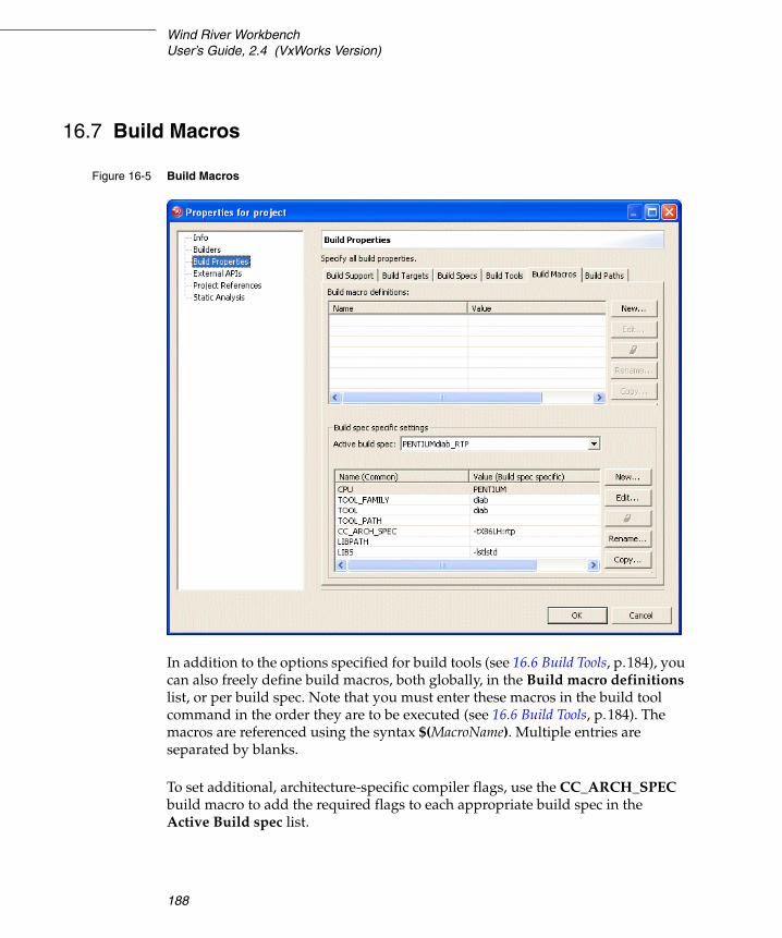
Wind River WorkbenchUser’s Guide, 2.4 (VxWorks Version)
188
16.7 Build Macros
In addition to the options specified for build tools (see 16.6 Build Tools, p.184), you can also freely define build macros, both globally, in the Build macro definitions list, or per build spec. Note that you must enter these macros in the build tool command in the order they are to be executed (see 16.6 Build Tools, p.184). The macros are referenced using the syntax $(MacroName). Multiple entries are separated by blanks.
To set additional, architecture-specific compiler flags, use the CC_ARCH_SPEC build macro to add the required flags to each appropriate build spec in the Active Build spec list.
Figure 16-5 Build Macros

16 Build Properties and the Build Console16.7 Build Macros
189
16
Setting the TOOL_PATH Macro
When specifying the path to a different compiler than the default one for your project, it is critical to specify the final slash ( / ) in the TOOL_PATH field of the Build spec specific settings table.
Specifying a New Compiler Version for a Single Project
If you have projects that were created for VxWorks 6.1, the default Wind River compiler version recognized by these projects is 5.2.3.0. In this release, VxWorks 6.2 ships with Wind River compiler version 5.3.1.
So if you want to use the new compiler with a project that originally recognized the old version, you must specify the path to the compiler root directory:
$(WIND_HOME)/diab/5.3.1/bsp/bin/
not:
$(WIND_HOME)/diab/5.3.1/bsp/bin
In the Workbench build system, and in a development shell if you have set up an appropriate build environment1, $(WIND_HOME) defaults to your Workbench installation directory.
This is the same directory represented by installDir elsewhere in the Workbench documentation, but in that case it is a convenient way to represent your installation path, whereas in the build system and on the command line, $(WIND_HOME) is an actual variable.
If you installed your compilers in a different location, substitute the appropriate path for $(WIND_HOME).
Specifying a New Compiler Version for All Projects
If you want all your projects to use the new compiler version, it is easier to change the specified compiler version in the installDir/install.properties file.
In the install.properties file for VxWorks 6.1, you will see a line that represents your default toolchain-platform version association:
1. For information about setting up a build environment, see the VxWorks Command-Line User’s Guide: Creating a Development Shell with wrenv.
NOTE: The path to the compiler root directory must be make-compliant, so even on Windows, you must use forward slashes throughout. Backslashes will be misinterpreted by make.
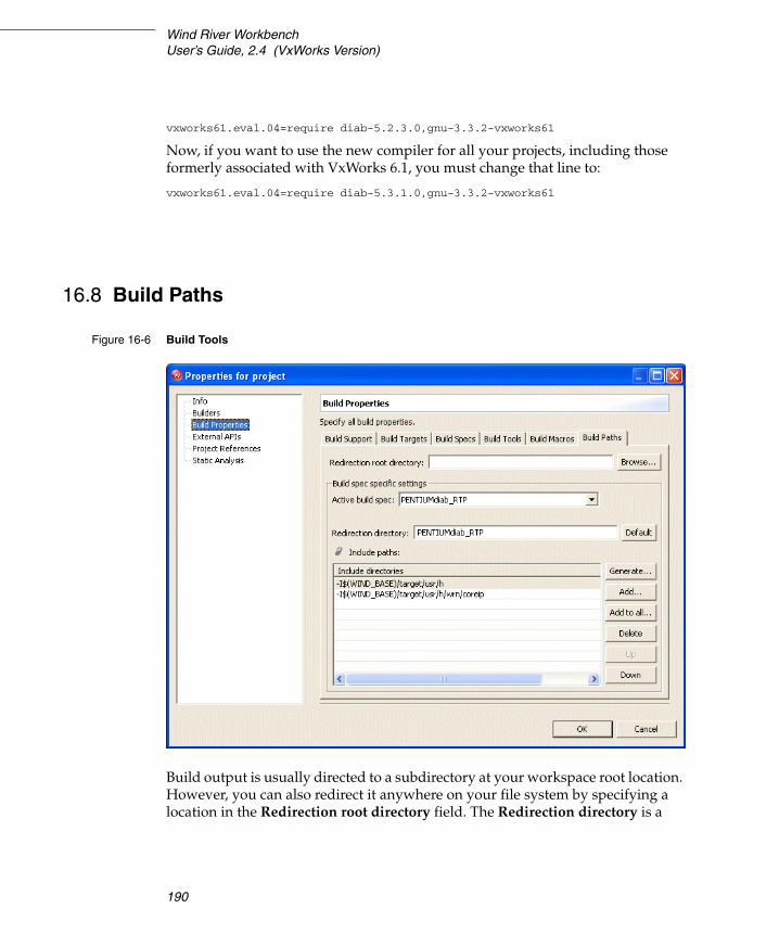
Wind River WorkbenchUser’s Guide, 2.4 (VxWorks Version)
190
vxworks61.eval.04=require diab-5.2.3.0,gnu-3.3.2-vxworks61
Now, if you want to use the new compiler for all your projects, including those formerly associated with VxWorks 6.1, you must change that line to:
vxworks61.eval.04=require diab-5.3.1.0,gnu-3.3.2-vxworks61
16.8 Build Paths
Build output is usually directed to a subdirectory at your workspace root location. However, you can also redirect it anywhere on your file system by specifying a location in the Redirection root directory field. The Redirection directory is a
Figure 16-6 Build Tools

16 Build Properties and the Build Console16.8 Build Paths
191
16
subdirectory of the Redirection root directory. By Default this directory has the same name as the Active build spec.
If the build-generated files should not be generated within the source code tree, and absolute redirection root directory can be used. In a team setting this may be problematic, as the value of this directory is stored within the .wrproject file, so it may potentially not be shareable if team members have different hardware setups, for instance. One user could specify a redirection path that does not exist on other team member’s machines. To avoid this problem, define environment variables that every team member can use. For example, you can define a variable called REDIRECTION_ROOTDIR and specify the absolute redirection root in the project properties as $REDIRECTION_ROOTDIR. Every team members can now set the environment variable to fit their needs, while the information stored in the .wrproject file becomes user/machine independent.
Supported environment variables are:
– The environment in which Workbench was started (specified outside of Workbench)
– The environment variables defined in the Workbench package (WIND_HOME, WIND_TOOLS, etc.)
– The environment variables of the target platform of the project (for instance WIND_BASE for vxworks-6.2)
The environment variables must be specified in UNIX or make notation:
$ENV/additional-path or $(ENV)/additional path
The list of Include paths used by the compiler can be correctly generated for directories that are visible (that is, they are in projects) and are unambiguous in the current workspace using the Generate button.
There are different contexts in which include search paths can be manually added:
■ Clicking Generate calls a wizard (see 16.8.1 The Generate Include Search-Paths Wizard, p.192) that allows you to manually add include search paths that will be seen in the context of the current Active build spec and the current project.
■ The Add button lets you add include search paths that will be seen in the context of the current Active build spec and the current project.
NOTE: Make macros that are defined within the project are not supported.

Wind River WorkbenchUser’s Guide, 2.4 (VxWorks Version)
192
■ The Add to all button lets you add include search paths that will be seen in the context of enabled build specs (these are visible in the Active build spec drop-down; see also 16.5 Build Specs, p.181) and the current project.
■ You can use the Up and Down arrows to change the order in which the directories are searched to fix ambiguities. The list is processed from top to bottom, and the first find wins.
16.8.1 The Generate Include Search-Paths Wizard
You can call up the Generate Include Search-Paths wizard from a number of places:
■ the Generate button in the Properties dialog of projects, folders, and files
■ the context menu in the Project Navigator
■ the dialog that appears the first time you build an application or library
The Generate Include Search Paths wizard always sets the include search path in the context of the current folder, whereby there is no distinction between folder types (project or normal folders).
The first page of the wizard tells you the current Folder context for which the include search paths can set.
You can also select whether or not to Ignore non-active includes (code that is not compiled because of preprocessor directives), and whether or not to Ignore system includes.
The list under Substitute paths (or path segments) with selected build macros allows you to select strings that are segments of absolute paths found on your local machine, to be replaced by macros. This facilitates sharing across different environments in team development. The list is pulled together from a number of sources in your current environment, namely:
■ from user and system environment variables
■ from environment variables that are set when you start up the Wind River Workbench
■ from build macros
If a Path Segment is checked, the corresponding Build Macro will be used in the include search path, rather than the absolute reference.

16 Build Properties and the Build Console16.9 Build Properties for VxWorks Image Projects
193
16
Click Resolve on the second page of the wizard to resolve include directives that were found in files in the current project or folder and add the corresponding Include Search Paths. Includes can be resolved if they are in open projects in the workspace. If there are unresolved directives, this is reported in the upper list and you can Add Folders manually. You can also change the order of the search paths to fix possible ambiguities.
The third page of the wizard (only available if called before the first build of a project or from the Project Navigator context menu), allows you to specify the scope of application, both in terms of folder/project and build specs.
16.9 Build Properties for VxWorks Image Projects
In general, the Build Properties tabs offer fewer options for VxWorks Image projects than for other project types. The Build Support and Build Target tabs do not appear at all for VIPs, while a separate tab allows you to specify link order for object files.
16.9.1 Build Specs for VIPs
Build specs for a VxWorks Image project are determined by the board support package (BSP) used to create the project. (Simulator BSPs usually offer only one build spec.) Use the Build Specs tab to enable and disable build specs or set the active build spec. Disabled (unselected) build specs are still in the project file, but they don’t appear the Workbench UI. See 16.5 Build Specs, p.181 for more information.
16.9.2 Build Tools for VIPs
See 16.6 Build Tools, p.184 for more information.
16.9.3 Build Macros for VIPs
Build macros for VxWorks Image projects are set on a per-build-spec basis, not globally. See 16.7 Build Macros, p.188 for more information.
Wind River WorkbenchUser’s Guide, 2.4 (VxWorks Version)
194
16.9.4 Build Paths for VIPs
Use this tab to add, delete, or reorder the directories searched by the build tools. See 16.8 Build Paths, p.190 for more information.
16.9.5 Link Order for VIPs
Specify the order in which object files are linked to create the VxWorks image.
16.10 Folder, File, and Build-Target Properties
Folders, files, and build-targets inherit (reference) project build properties where these are appropriate and applicable. However, these properties can be overwritten at the folder/file level. Inherited properties are displayed in blue typeface, overwritten properties are displayed in black typeface.
Overwritten settings are maintained in the .wrproject and .wrfolder files. These files should therefore also be version controlled. Note that you can revert to the inherited settings by clicking the eraser icon next to a field.
16.11 Makefiles
The build system uses the build property settings to generate a self-contained makefile named Makefile in each project and folder at each build run. This allows you to build individual folders, projects, and subtrees in a project structure. By default makefiles are stored in project directories; if an absolute Redirection Root Directory (see 16.8 Build Paths, p.190) has been specified, they are stored there, in subdirectories that match the project directory names.
The generated makefile is based on a template makefile named .wrmakefile that is copied over at project creation time. If you want to use custom make rules, enter these in .wrmakefile, not in Makefile because this is regenerated for each build. The template makefile, .wrmakefile, references the generated macros in the

16 Build Properties and the Build Console16.11 Makefiles
195
16
placeholder %IDE_GENERATED%, so you can add custom rules either before or after this placeholder. However, there are also other ways of setting custom rules, see 17.7 User-Defined Build-Targets in the Project Navigator, p.210.
16.11.1 Derived File Build Support
The Yacc Example
Workbench provides a sample project, yacc_example, that includes a makefile extension showing how you can implement derived file build support. It is based on yacc (Yet Another Compiler Compiler) which is not contained in the Workbench or VxWorks installation. To actually do a build of the example you need to have yacc or a compatible tool (like GNU’s bison) installed on your system, and you should have extensive knowledge about make.
The makefile, yacc.makefile, demonstrates how a yacc compiler can be integrated with the managed build and contains information on how this works.
1. Create the example project by selecting New > Project > Example > Native Sample Project > Yacc Demonstration Program.
2. Right-click the yacc_example project folder, then select New > Build Target. The New Build Target dialog appears.
3. In the Build target name field, type pre_build.
4. From the Build tool drop-down list, select (User-defined), then click Finish to create the build target.
5. In the Project Navigator, right-click pre_build and select Build Target. This will use the makefile extension yacc.makefile to compile the yacc source file to the corresponding C and header files. The build output appears in the Build Console.
6. When the build is finished, right-click the yacc_example folder and select Build Project.
NOTE: It is necessary to execute this build step prior to the project build, because the files generated by yacc will not be used by the managed build otherwise. This is due to the fact that the managed build generates the corresponding makefile before the build is started and all files that are part of the project at this time are taken into account.

Wind River WorkbenchUser’s Guide, 2.4 (VxWorks Version)
196
Additional information on how you can extend the managed build is located in yacc.makefile. It makes use of the extensions provided in the makefile template .wrmakefile, which can also be adapted to specific needs.
General Approach
To implement derived file support for your own project, create a project-specific makefile called name_of_your_choice.makefile. This file will automatically be used by the managed build and its make-rules will be executed on builds.
It is possible to include multiple *.makefile files in the project, but they are included in alphabetical order. So if multiple build steps must be done in a specific order, it is suggested that you use one *.makefile and specify the order of the tools to be called using appropriate make rules.
For example:
1. Execute a lex compiler.
2. Execute a yacc compiler (depending on lex output).
3. Execute a SQL C tool (depending on the yacc output).
Solution: (using the generate_sources make rule)
generate_sources :: do_lex do_yacc do_sqldo_lex:
@...
do_yacc:@...
do_sql:@...
or
generate_sources :: $(LEX_GENERATED_SOURCES) $(YACC_GENERATED_SOURCES) $(SQL_GENERATED_SOURCES)
Add appropriate rules like those shown in the file yacc.makefile.

16 Build Properties and the Build Console16.12 Build Console View
197
16
16.12 Build Console View
When you launch a build, the Build Console view comes to the foreground to display each step of the build (you can toggle this by selecting or unselecting Activate Build Console on building from the Build Console toolbar). The information displayed in the Build Console includes the full command line, when the build started and finished, as well as any errors.
If a particular line of output interests you and you do not want it to scroll out of view, click the Scroll Lock icon. The Build Console continues to accumulate information, but the display does not refresh until you click Scroll Lock again to release it.
Double-click an error to navigate to the offending line in the source file.
16.12.1 Saving Build Output
To save your build output to a Build.log file, click the Save icon. Log files are saved to installDir/host/platform/bin/Build.log by default, but you can save them anywhere you like.
16.12.2 Build Console Preference Settings
To display the output of each build separately, select Clear Build Console before new Build Run. This is useful if you save build output to log files. To display build results sequentially, clear this check box.
Specify the color, text style, and regular expression you want to display for each type of result in the Build Console view.
To pass all build output through the error parsers before displaying it in the Build Console view, select Use Diab Error Parser or Use Gnu Error Parser. This will create links in the Tasks view between any build errors and the line in your source code containing the errors.
If you do not use the parsers, the errors will still appear in the Tasks view, but you will not be able to double-click them to navigate to the corresponding line of source code. You will have to navigate to the errors manually.

Wind River WorkbenchUser’s Guide, 2.4 (VxWorks Version)
198

199
17 Building: Use Cases
17.1 Introduction 199
17.2 Adding Compiler Flags 200
17.3 Building Applications for Different Boards 202
17.4 Creating Library Build-Targets for Testing and Release 203
17.5 Architecture-Specific Implementation of Functions 206
17.6 Executables that Dynamically Link to Shared Libraries 207
17.7 User-Defined Build-Targets in the Project Navigator 210
17.8 A Build Spec for New Compilers and Other Tools 211
17.9 Developing on Remote Hosts 213
17.1 Introduction
This chapter suggests some of the ways you can go about completing various build-specific tasks in Wind River Workbench.

Wind River WorkbenchUser’s Guide, 2.4 (VxWorks Version)
200
17.2 Adding Compiler Flags
Let us assume:
1. You are working on a Real-time Process project (referred to in the following as MyRTP), and you are using the build spec, SIMPENTIUMgnu_RTP.
2. You want to suppress compiler warnings, and you are familiar with the GNU compiler (used by the given build spec) command line.
3. You later have to change the build spec to SIMPENTIUMdiab_RTP; that is you have to use the Wind River Compiler tools, with which you are not familiar, but you still want to suppress compiler warnings.
17.2.1 Add a Compiler Flag by Hand
According to assumption 2, above, you are familiar with the GNU compiler command line, so you just want to know where to enter the -w option.
1. In the Project Navigator, right-click on the MyRTP project and select Properties.
2. In the Properties dialog, select the Build Properties node.
3. In the Build Properties node, select the Build Tools tab.
4. In the Build Tools tab:
– Set the Build tool to C-compiler
– The Active build spec will, according to assumption 1, above, already be set to SIMPENTIUMgnu_RTP.
– In the field next to the Tool Flags button, append a space and -w
The contents of this, the Tool Flags field you have just modified, is expanded to the %ToolFlags% macro you see in the Command field above it. Because you entered the -w in the Tool Flags field, rather than the Debug or Non Debug mode fields, warnings will always be suppressed, rather than only in either Debug or Non Debug mode.

17 Building: Use Cases17.2 Adding Compiler Flags
201
17
17.2.2 Add a Compiler Flag with GUI Assistance
According to assumption 3, above, you have to change to the Wind River Compiler tool chain used by the SIMPENTIUMdiab_RTP build spec, and you are not familiar with the new command line tool options.
Step 1: Change the Active Build Spec
1. In the Project Navigator, right-click on the MyRTP project, and select Set Active Build Spec.
If the SIMPENTIUMdiab_RTP build spec is enabled, you will see it listed in the dialog that appears. In this case, all you would have to do is select SIMPENTIUMdiab_RTP from the list and click OK.
However, we shall assume SIMPENTIUMdiab_RTP is not enabled, and therefore not available in the list.
2. In the Project Navigator, right-click on the MyRTP project, and select Properties.
3. In the Properties dialog, select the Build Specs node.
4. In the Build Specs node, select the SIMPENTIUMdiab_RTP build spec and set both the Default build spec and the Active build spec to SIMPENTIUMdiab_RTP.
Leave the Properties dialog open to complete Step 2, below.
Step 2: Use the GUI to Add a Compiler Flag
1. Select the Build Tools tab.
2. In the Build Tools tab:
– Set the Build tool to C-compiler
– The Active build spec will already be set to SIMPENTIUMdiab_RTP (see 4 above).
– We assumed you are unfamiliar with the Wind River compiler options so, to open the Wind River Compiler Options dialog, click the Tool Flags button.
Wind River WorkbenchUser’s Guide, 2.4 (VxWorks Version)
202
– In the Wind River Compiler Options dialog, click your way down the navigation tree at the left of the dialog and take a look at the available options.
When you get to the Compilation > Diagnostics node, select the check box labelled Suppress all compiler warnings.
Notice that -Xsuppress-warnings now appears in the list of command line options at the right of the dialog.
Click OK.
3. Back in the Build Tools node of the Properties dialog, you will see that the option you selected now appears in the field next to the Tool Flags button.
The contents of this, the Tool Flags field, is expanded to the %ToolFlags% macro you see in the Command field above it.
17.3 Building Applications for Different Boards
Generally, but not necessarily, you would have a VxWorks Image project (VIP) for each architecture you support. If, however, you are developing applications and/or libraries only, you might not have VIPs.
If you do have VIPs, you will probably only set the build spec once for the application subprojects to match the VIP they are under. On the other hand, if you do not have VIPs, you might switch the build spec to build projects for different architectures.
The target nodes under projects in the Project Navigator display, in blue, the name of the currently active build spec.
If, for example, you want to build an application for testing on a simulator, and then build the same project to run on a real board, you would simply switch build specs as follows:
1. Right-click the project or the target node and, from the context menu, select Set Active Build Spec.

17 Building: Use Cases17.4 Creating Library Build-Targets for Testing and Release
203
17
2. In the dialog that appears, select the build spec you want to change to and specify whether or not you want debug information.
When you close the dialog, you will notice that the label of the target node has changed. If you selected debug mode in the dialog, the build spec name is suffixed with _DEBUG.
3. Build the project for the new architecture.
17.4 Creating Library Build-Targets for Testing and Release
Assume you have a library that consists of the files source1.c, source2.c, and test.c. The file test.c implements a main( ) function and is required exclusively for testing, and is not to be included in the release version of the library.
One way to handle this is to use different targets that are built with different tools as described below.
1. Create a Real-time Process project to hold all the files mentioned above. Use this project type, because you will need to use both the Linker and the Librarian build tools later.
In the first page of the project creation wizard, name the project, for example, LIB and click Finish. You will need to do some tweaking in the Project’s Properties dialog anyway, so you might as well do everything there.
2. Right-click the newly created LIB project, and select Properties. In the Properties dialog, select the Build Properties node, then the Build Targets tab.
First create a build-target for the release version of your library.
– Change the Build tool to Librarian.– Select Pass build target to next level.– Clear the Use default contents and link order check box. – Clear the check box next to test.c.– Click Apply.
Figure 17-1 shows the results.
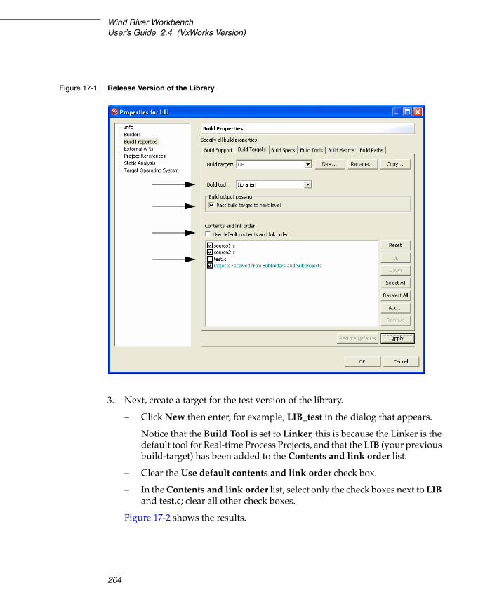
Wind River WorkbenchUser’s Guide, 2.4 (VxWorks Version)
204
3. Next, create a target for the test version of the library.
– Click New then enter, for example, LIB_test in the dialog that appears.
Notice that the Build Tool is set to Linker, this is because the Linker is the default tool for Real-time Process Projects, and that the LIB (your previous build-target) has been added to the Contents and link order list.
– Clear the Use default contents and link order check box.
– In the Contents and link order list, select only the check boxes next to LIB and test.c; clear all other check boxes.
Figure 17-2 shows the results.
Figure 17-1 Release Version of the Library

17 Building: Use Cases17.4 Creating Library Build-Targets for Testing and Release
205
17
After you close the Properties dialog, there will be two new build-target nodes in the LIB project. If you build LIB_test, then LIB will automatically also be built if it is out of date.
Figure 17-2 Test Version of the Library

Wind River WorkbenchUser’s Guide, 2.4 (VxWorks Version)
206
17.5 Architecture-Specific Implementation of Functions
You can enable/disable build specs at the project as well as at the folder level. This allows architecture-specific implementation of functions within same project.
Figure 17-3 shows a simplified project tree with two subprojects, arch 1 and arch2, that each use code that is specific to different target architectures. This is how projects could be set up to build a software target that requires the implementation of a function that is specific to different target boards, where only the active build spec in the topmost project has to be changed. The inner build spec relationships are outlined in Table 17-1.
The function int arch_specific (void) is declared in arch.h and the file arch1.c implements int arch_specific (void) for PENTIUM (the only build spec enabled for the arch1 project), while the file arch2.c implements int arch_specific (void) for PPC32 (the only build spec enabled for the arch2 project).
If the active build spec for project is set to PENTIUMdiab_RTP, the subproject arch1 will be built, and its objects will be passed up to be linked into the project
Figure 17-3 Simple Project Structure for Architecture-Specific Functions
Table 17-1 Project Content and Build Spec Configuration of the Structure in Figure 17-3
Directories/Folders Files Enabled Build Specs
/project main.c, arch.h PENTIUMdiab_RTP and PPC32diab_RTP
/project/arch1 arch1.c PENTIUMdiab_RTP only
/project/arch2 arch2.c PPC32diab_RTP only

17 Building: Use Cases17.6 Executables that Dynamically Link to Shared Libraries
207
17
build-target. The arch2 subproject will not be built, and its objects will not be passed up to be linked into the project build target because the PENTIUMdiab_RTP build spec is not enabled for arch2.
The same applies if the PPC32diab_RTP is the active build spec for project: the arch2 subproject will be built, but the arch1 subproject will not.
17.6 Executables that Dynamically Link to Shared Libraries
Only executables produced from RTP projects can dynamically link to shared libraries. Note that you will need a VxWorks File System project for a ROMFS file system to hold the library binary on the target. The compiled library must be located in the host and target side directories you specify as described below.
Step 1: Modify the Real-time Process build-target build properties.
1. Right-click the RTP’s target node and select Properties.
2. In the Properties dialog, select the Build Properties node.
Step 2: Set up the Linker Build Tool for a dynamic executable and target-side run path.
1. Select the Build Tools tab.
2. In the field next to the Tool Flags button, enter the run path (-rpath) to the directory that will hold the shared library on your target, for example, -rpath /romfs/lib (romfs is the default root directory of the ROMFS created by File System projects).
3. Click Tool Flags.

Wind River WorkbenchUser’s Guide, 2.4 (VxWorks Version)
208
4. In the Linker Options dialog that appears, select Create a dynamic executable.
You will notice that the option, as used on the command line, appears in the Selected Options list on the right. After you click OK to close the Linker Options dialog, you will see the option again in the field next to the Tool Flags button.
Figure 17-4 Build Options for Dynamic Executables

17 Building: Use Cases17.6 Executables that Dynamically Link to Shared Libraries
209
17
Step 3: Define Build Macros for the host-side location and library binary.
1. Select the Build Macros tab.
2. In the list of Build spec specific settings, select the LIBS macro and click Edit.
In the dialog that appears, add a space after the existing value (-lstlstd), followed by the basename of the shared library binary you want to link to, for example, MyLibrary:
-l:MyLibrary.so
When you close the dialog you should see:
LIBATH -lstlstd -l:MyLibrary.so
3. In the list of Build spec specific settings, select for the LIBPATH macro and click Edit.
In the dialog that appears, enter the host-side directory location of the library binary you want to dynamically link to, for example:
-L../MyLibrary/$(OBJ_DIR)
Note that $(OBJ_DIR) expands to wherever the build output for MyLibrary is generated to. Using $(OBJ_DIR) is generic and therefore offers the advantage of not having to change the LIBPATH macro if you change build specs.
Note further that the relative reference assumes the Shared Library project is located in the same workspace as the Real-time Process project.
Click OK to close the project’s build-target Properties dialog.
The next time you build the project structure, a dynamic executable capable of run-time linking to the shared library with the file basename and the directories (host and target side) you specified above will be produced.
NOTE: If your application is not built as described in this section (17.6 Executables that Dynamically Link to Shared Libraries, p.207), you must set the LD_LIBRARY_PATH environment variable.
Click Edit beside the Environment field, then click Add in the Edit Environment dialog, then type LD_LIBRARY_PATH in the Name field and the full path to your shared library file (using forward slashes and excluding the filename itself) in the Value field. The path must be defined in terms of the file system as seen on the target.
Click OK. The Edit Environment dialog should contain the new environment variable; click OK.

Wind River WorkbenchUser’s Guide, 2.4 (VxWorks Version)
210
17.7 User-Defined Build-Targets in the Project Navigator
In the Project Navigator you can create custom build-targets that reflect rules in makefiles. This is especially useful if you have User-Defined projects, which are projects where the build is not managed by Workbench. However, you might also find this feature useful in other projects as well.
17.7.1 Custom Build-Targets in User-Defined Projects
Assuming you have two rules in a makefile, clean and all, you can define a custom build-target for either or both of these rules. To do so:
1. Right-click a project or folder and select New > Build Target.
2. In the dialog that appears, enter the rule(s) you want to create a target for. If you want to execute multiple rules, separate each one with a space.
In our example, enter clean all to have both these rules, which must exist in your makefile(s), executed when you build your new user-defined target.
Click Finish. The new build-target node appears under the project or folder you selected. The node icon has a superimposed M to identify it as a user-defined make rule.
To execute the rule(s), right-click the new target node and select Build Target.
17.7.2 Custom Build-Targets in Workbench Managed Projects
First write the make rules you need into the .wrmakefile file in the project directory.
1. Right-click a project or folder and select New > Build Target.
2. In the dialog that appears, enter the rule name(s) you created in .wrmakefile. If you want to execute multiple rules, separate each one with a space.
Set the Build tool to User-defined, click Finish.
The new build target node appears under the project or folder you selected. The node icon has a superimposed M to identify it as a user-defined rule.
To execute the rule(s), right-click the new target node and select Build Target.

17 Building: Use Cases17.8 A Build Spec for New Compilers and Other Tools
211
17
17.7.3 User Build Arguments
You can use the User Build Arguments view to execute any existing make rule, or overwrite any macro, or anything else that is understood by make, at every build, regardless of what is being built. The view is toggled by choosing User Build Arguments view from the drop-down menu at the top right of the Project Navigator, or by clicking the button in the Project Navigator’s toolbar.
If the User Build Arguments check box is selected, the rule, or rules separated by a space, or macro re-definitions, and so on will override the makefile entries on the fly at every build, regardless of context.
17.8 A Build Spec for New Compilers and Other Tools
The easiest way to define a build spec for a new compiler and other associated tools (known as a tool chain) is to copy one of the pre-configured build specs of an existing tool chain and architecture, and modify the copy.
Step 1: Copy an Existing Build Spec.
1. Open an application project’s, for example an RTP, build properties as described under 16.2 Accessing Build Properties, p.175.
Using an application project has the advantage that these have a fuller range of generic build tools (Assembler, language-specific Compiler, Librarian, and Linker).
2. Select the Build Specs tab and look at the existing specs. The pre-configured build spec names follow an ArchitectureToolChain_ProjectType convention, for example, PENTIUMgnu_RTP. This spec is configured for a Pentium target board, using GNU tools to create an Real-time Process (RTP).
In the Build Specs tab, select the build spec that comes closest to your needs, at least in terms of target architecture, or a tool chain that you are familiar with, and click Copy.
You will be warned that build properties need to be saved before proceeding. Click OK, then enter a name for the copy you are creating in the next dialog and click OK again.

Wind River WorkbenchUser’s Guide, 2.4 (VxWorks Version)
212
3. Still in the Build Specs tab, set the Active build spec to your newly created copy (this is initially right at the bottom of the list of Available and enabled build specs. Whatever you set here is also propagated to the following tabs (described in more detail in 16. Build Properties and the Build Console):
■ Build Tools, p.184■ Build Macros, p.188■ Build Paths, p.190
Each of these tabs has a generic section at the top with Build spec specific settings below. The generic section will normally be correct, which is one advantage of copying an existing spec, rather than creating a new spec from the beginning.
Step 2: Configure the Build Tool.
The build system uses generic build tools, for example, a C-Compiler. So if you are adding a new, unsupported C compiler, you will have to configure a build spec that understands this specific instance of the generic C-Compiler build tool. Using the compiler as an example, proceed as follows:
1. Select the Build Tools tab and set the Build tool drop-down list to C-Compiler.
The generic settings regarding Suffixes and Build output generation should be correct, if not modify accordingly. (If you were adding a compiler for a new language, foolanguage, you could first create a Copy of a generic C-Compiler Build tool and name that, for example, Foo-Compiler, and then configure the generic settings as required.)
2. In the Build spec specific settings you would configure the options that are specific to your particular compiler.
– The Active build spec should already be set to your newly created build spec.
– The Derived suffix refers to the file suffix of the compiler’s output.
– The Command is the command line call to your compiler with all the options you want to pass.
In theory, you could simply type a hard command in this field. However, using the predefined macros of the form %MacroName% and macros (your own and/or pre-defined) that are defined on the Macros tab and referenced using $(MacroName) generally makes more sense, as does

17 Building: Use Cases17.9 Developing on Remote Hosts
213
17
separating common Tool Flags and Debug mode and Non Debug mode flags. For more detailed information please refer to 16.6 Build Tools, p.184.
3. If you are using your own and/or pre-defined using macros in the Command field, set these in the Build Macros tab.
For more detailed information please refer to 16.7 Build Macros, p.188.
4. In the Build Paths tab, configure the redirection directories for build output and set the include search paths (if applicable; that is, if you are configuring a build spec for a C/C++ compiler) using the Generate and Add buttons.
For more detailed information please refer to 16.8 Build Paths, p.190.
After you have configured the build spec for the first tool in the chain, for example, the compiler, go back to the Build Tools tab (see Step 2, above) to configure any additional tools, such as the Linker or Librarian.
17.9 Developing on Remote Hosts
The Workbench remote build feature allows you to develop, build and run your applications on a local host running Workbench, using a workspace that is located on a remote host as if it were on a local disk.
In the case of a managed build, Workbench generates the makefiles on the local machine running Workbench using a path mapping of the workspace root

Wind River WorkbenchUser’s Guide, 2.4 (VxWorks Version)
214
location, so that the generated makefiles will be correctly dumped for a build that is executed on the remote machine. When launching the build, a network connection (rlogin) is established to the build host, and the actual build command is executed there by using an intermediate script to allow you to set up the needed environment for the build process.
17.9.1 General Requirements
■ The workspace root directory has to be accessible from both machines.
■ Only Eclipse projects located underneath the workspace root can be remotely built.
■ A rlogin remote connection to the build machine must be possible.
17.9.2 Remote Build Scenarios
Local Windows, Remote UNIX:
The workspace root directory should be located on the remote UNIX host and mapped to a specific network drive on Windows. It may also be possible to locate the root directory on the Windows machine, but then there is the need to mount the Windows disk on the build host. This may lead to problems regarding permissions and performance, so a mapping of the workspace root-directory is definitely needed.
Local UNIX, Remote UNIX:
As it is possible to access the workspace root directory on both machines with the equivalent path (automount) it may be possible to skip the path mapping.
Local UNIX, Remote Windows:
This scenario is not supported, as you would need to execute the build command on Windows from a UNIX host.

17 Building: Use Cases17.9 Developing on Remote Hosts
215
17
17.9.3 Setting Up a Remote Environment
To set up your environment on the remote machine prior to a build or run, use the Edit remote command script button to include additional commands. It will open the file workspaceDir/.metadata/.plugins/com.windriver.ide.core/remote_cmd.sh.
For example, to extend the path before a build, add the highlighted lines to the default file:
#!/bin/sh
WORKSPACE_ROOT="%WorkspaceRoot%"export WORKSPACE_ROOTDISPLAY=%Display%export DISPLAY
PATH=/MyTools/gmake_special/bin:$PATHexport PATH
cd $WORKSPACE_ROOT
cd "$1"shift 1
exec "$@"
You can add any commands you need, but all commands must be in sh shell style.
17.9.4 Building Projects Remotely
1. Switch to a workspace that contains existing projects by selecting File > Switch Workspace. Type the path to the appropriate workspace, or click Browse and navigate to it.
2. In the Project Navigator, right-click a project and select Build > Remote Connection. The Remote Connections dialog appears.
3. Click Add and type a descriptive name for this remote connection. Click OK.
4. In the Connection Settings fields, add the following information to create a remote connection:
Hostname The name of the build host (can also be an IP address).
Username The username used to establish the connection (the remote user may differ from the local user).

Wind River WorkbenchUser’s Guide, 2.4 (VxWorks Version)
216
Remote Workspace Location The root directory of the workspace as seen on the remote host.
Display (XServer)IP address of the machine where the output should be displayed.
By clicking the Advanced button you can also access these fields:
Password request string A string that will be recognized as a password request to prompt you for the password.
Remember Password during Workbench sessionsA switch to specify whether the password entered should be remembered during the current session. This is useful during a lengthy build/run session.
5. Click Connect to connect immediately. Remote connection settings are stored, and are specific to this workspace. They are not accessible from any other workspace.
6. The build is executed on the remote host, with the build output listed in the standard Workbench Build Console. The XServer (IP address listed in the Display field) is used whenever any type of X application is started, either during builds or runs.
7. To return to local development, select Local Host from the list of connections, then click Connect.
17.9.5 Running Applications Remotely
This section provides information about running native applications only, as running VxWorks projects remotely is handled differently.
Running native applications remotely is quite similar to running applications locally: a Native Application launch configuration must be created that defines the executable to be run, as well as remote execution settings for the launch. On the Remote settings tab are:
Remote ProgramEnter the command that is used to launch the application. This may be useful for command-line applications that could then be launched within an xterm, for instance.

17 Building: Use Cases17.9 Developing on Remote Hosts
217
17
Remote Working DirectoryThis setting is optional, but if a remote working directory is given, it overrides the entry in the Working Directory field of the Arguments tab.
For remote runs, a new connection similar to the active connection will be established to allow control of Eclipse process handling, as the new remote process will be shown in the Debug view. The Remember password during Workbench sessions feature is very useful here.
Command-line application’s output and input is redirected to the standard Eclipse console unless the application is started within an external process that creates a new window (such as xterm). The default for remote execution is a remote command like xterm -e %Application%, therefore a local XServer (like Exceed or Cygwin X) must be set up and running.
For more information about creating launch configurations, see 23. Launching Programs.
17.9.6 Rlogin Connection Description
The rlogin connection used in the Workbench remote build makes use of the standard rlogin protocol and ports. It establishes a connection on port 513 on the remote host, and the local port used must be in the range of 512 to 1023 per rlogin protocol convention.
On Windows the rlogin connection is implemented directly from within Workbench, so you do not need an existing rlogin client. The UNIX implementation is different, because for security reasons the local port (range: 512 to 1023) is restricted to root access, which cannot be granted from within Workbench. Therefore an external rlogin process is spawned using the command-line:
rlogin -l username hostname
rlogin on UNIX platforms makes use of setUID root to ensure that the needed root privileges are available.
The standard rlogin protocol doesn't support access to stderr of the remote connection, to all output is treated as stdout. Coloring in the Build Console of Workbench for stderr is therefore not available.

Wind River WorkbenchUser’s Guide, 2.4 (VxWorks Version)
218
NOTE: On Linux the rlogin client and server daemon can be switched off per default. So if the machine is used as a Workbench (remote build client) host, the rlogin executable must be enabled (or built) and if the machine is acting as build server (remote build host) the rlogin daemon must be enabled. Details may be found in the system documentation of the host.

219
18RTPs and Shared Libraries
from Host to Target
18.1 Introduction 219
18.2 A VxWorks Real-time Process from Host to Target 220
18.3 A VxWorks Shared Library from Real-time Process to Target 225
18.1 Introduction
This chapter uses hands-on examples to illustrate one of the ways you might set up, build, and run VxWorks Real-time Processes and VxWorks Shared Libraries from host to target. The target used will be a VxWorks Simulator.
The Shared Library hands-on (18.3 A VxWorks Shared Library from Real-time Process to Target, p.225) follows from the Real-time Process hands-on, and therefore assumes that you have completed the steps outlined under 18.2 A VxWorks Real-time Process from Host to Target, p.220.

Wind River WorkbenchUser’s Guide, 2.4 (VxWorks Version)
220
18.2 A VxWorks Real-time Process from Host to Target
This section describes how to go about setting up a VxWorks Real-time Process. Although the section is self-contained, you will also need to set up a VxWorks Real-time Process with the infrastructure described here if you want to use a VxWorks Shared Library.
18.2.1 Set Up the Project Structure for Real-time Processes
You will need a VxWorks Image project, a VxWorks File System project, and a VxWorks Real-time Process project to start with. When this is done, you will need to add some code and to create a target connection to test the system.
Step 1: Set up a VxWorks image project.
1. In the Project Navigator, right-click and select New > VxWorks Image Project.
2. In the first wizard page, under Project name: type VxWorksSim and click Next.
3. In the next wizard page, set A board support package to simpc and click Finish.
Step 2: Set up a VxWorks File System project.
1. In the Project Navigator, be sure the project you have just created, VxWorksSim, is selected so that the new VxWorks File System project you are about to create will automatically become a subproject of VxWorksSim.
2. In the first wizard page, under Project name: type VxWorksSimFS, click Finish.
3. In the Project Navigator, expand the VxWorks Image project VxWorksSim project folder you created earlier. You will see the VxWorksSimFS project you have just created is a subproject of VxWorksSim.
Step 3: Set up a VxWorks Real-time Process project.
1. Right-click in the Project Navigator and select New > VxWorks Real Time Process Project.
2. In the first wizard page, under Project name: type MyRTP, click Finish.

18 RTPs and Shared Libraries from Host to Target18.2 A VxWorks Real-time Process from Host to Target
221
18
By default, the build spec SIMPENTIUMdiab_RTP_DEBUG will be activated for the project, which is fine because this will match the board support package you set for the VxWorks Image project in Step 1, above.
Step 4: Add the Real-time Process to the File System project.
In the Project Navigator, drag-and-drop the MyRTP project onto the VxWorksSimFS project (the VxWorksSim project must be expanded).
Figure 18-1 shows the project setup so far (note that .* files have been filtered out).
Step 5: Set up the target file system.
18.2.2 Add Code to the Real-time Process Project
You need some code that will let you verify that everything works.
1. In the Project Navigator, right-click MyRTP, select New > File from Template, and under File Name: type MyRTP.c.
Click Finish; the file MyRTP.c opens in the Editor view.
Figure 18-1 Project Hierarchy for a VxWorks Real-time Process

Wind River WorkbenchUser’s Guide, 2.4 (VxWorks Version)
222
2. In MyRTP.c change the following lines (the results are also shown in Figure 18-2):
Change:
#include “MyRTP.h”
to read:
#include <stdio.h>
Change the function:
void MyRTP(){}
to read:
int main(){
printf("MyRTP called!\n”);return 0;
}
Figure 18-2 shows the modified source file, MyRTP.c.
Leave the file open; you will need it again if you intend to go through 18.3 A VxWorks Shared Library from Real-time Process to Target, p.225.
Figure 18-2 The MyRTP.c Source

18 RTPs and Shared Libraries from Host to Target18.2 A VxWorks Real-time Process from Host to Target
223
18
18.2.3 Add the Real-time Process to the Target File System
Although you do not have a Real-time Process binary yet, you can make provision for the binary to be on the target file system once the system is built.
1. In the Project Manager, under the VxWorksSimFS File System project you created earlier, double-click the VxWorks File System Contents node to open the File System Contents Editor.
2. In the File System Contents Editor, click New Folder and under Name type bin.
The bin folder appears in the Target Contents panel.
3. In the Target Contents panel select the bin node, then in the Host Contents panel, expand the project nodes until you can see the target node that represents the (future) Real-time Process binary, namely: MyRTP.vxe (SIMPENTIUMdiab_RTP_DEBUG).
Select this node and click Add. The MyRTP.vxe binary (which does not yet exist) appears in the Target Contents panel under the bin folder.
Figure 18-3 shows the results.
Leave the File System Contents Editor open; you will need it again if you intend to go through 18.3 A VxWorks Shared Library from Real-time Process to Target, p.225.
Figure 18-3 The Executable on the Target File System

Wind River WorkbenchUser’s Guide, 2.4 (VxWorks Version)
224
18.2.4 Build the System
In the Project Navigator, right-click the VxWorks Image project, VxWorksSim, and select Build Project.
The structure is recursively built, starting in MyRTP, as you can see in the Build Console. Next the File System project, VxWorksSimFs, is built. The build finishes at the top, in VxWorksSim.
In the next step (Set up the Target Connection, p.224) you will need to know the location of the VxWorks kernel you have just built. You can see the path to this in the second to last line of the build console; copy this location for later pasting.
18.2.5 Set up the Target Connection
To test the system you have just built, you need to create a connection to the target.
1. In the Target Manager, right-click the default(localhost) registry icon and select New > Connection.
2. On the first wizard page, select Wind River VxWorks Simulator Connection and click Next.
3. On the next wizard page, select Custom Simulator and, if you copied the path to the VxWorks Kernel Image you have just built (under Build the System, p.224, above) paste this in the field and then either Browse to VxWorks, or enter /VxWorks.
In general terms, the location of the image is: WorkspaceDirectory/ProjectName/BuildSpecName/VxWorks whereby BuildSpecName in this case example would be default.
You have to select Custom Simulator because your image, unlike the Standard Simulator, has a VxWorks File System (FSROM) that holds a Real-time Process binary linked to it.
4. Continue to click Next until you reach the last wizard page (when the Finish button is enabled). At Connection name: type VxWorksSim. Leave the Immediately connect to target if possible check box selected. Click Finish.
The connection is immediately established and the Kernel Shell opens.
18 RTPs and Shared Libraries from Host to Target18.3 A VxWorks Shared Library from Real-time Process to Target
225
18
18.2.6 Run the Real-time Process on the Simulator
At the Kernel Shell prompt, type:
cd "/romfs/bin"
Press ENTER and type:
rtpSpawn "MyRTP.vxe"
Press ENTER again.
The output MyRTP called! should appear. Close the Kernel Shell.
18.3 A VxWorks Shared Library from Real-time Process to Target
Much of the initial work required for using a VxWorks Shared Library project is done under 18.2 A VxWorks Real-time Process from Host to Target, p.220. It is assumed you have completed all the steps in that section, and the procedures outlined below will follow on from there.
18.3.1 Set Up the VxWorks Shared Library Project
First, create a new VxWorks Shared Library project to add to the existing project structure you have already created under 18.2 A VxWorks Real-time Process from Host to Target, p.220.
1. Right-click in the Project Navigator and select New > VxWorks Shared Library Project and click Finish.
2. On the first wizard page, at Project name: type MyLibrary and click Finish.
Note that you have not set a build spec. The build spec for a Shared Library must match that used for the Real-time Process that will link to it. However, the default build spec for the Real-time Process you implicitly accepted above (see Step 4:Add the Real-time Process to the File System project., p.221) matches the default for Shared Libraries, namely SIMPENTIUMdiab_RTP_DEBUG.

Wind River WorkbenchUser’s Guide, 2.4 (VxWorks Version)
226
18.3.2 Add Code to the Shared Library Project
You need some code that will let you verify that everything works.
1. In the Project Navigator, right-click MyLibrary, select New > File from Template, and under File Name type MyLibrary.h. Click Finish; the file MyLibrary.h opens in the Editor view.
2. In the Project Navigator, right-click MyLibrary, select New > File from Template, and under File Name type MyLibrary.c. Click Finish; the file MyLibrary.c opens in the Editor view.
3. In MyLibrary.c add the following line:
#include <stdio.h>
4. Insert the following line into the MyLibrary function:
printf("MyLibrary called!\n");
Figure 18-4 shows the modified source file, MyLibrary.c.
5. Save MyLibrary.c.
Figure 18-4 The MyLibrary.c Source

18 RTPs and Shared Libraries from Host to Target18.3 A VxWorks Shared Library from Real-time Process to Target
227
18
18.3.3 Add the Shared Library to the Run-Time Process
The Shared Library must be built before the Real-time Process, so it is added as a subproject. Furthermore, the library binary must be located in the host and target side directories you specify as described below.
Step 1: Add the library as a subproject.
In the Project Navigator, drag-and-drop the MyLibrary project onto the MyRTP project.
Step 2: Modify the Real-time Process build-target build properties.
1. Right-click the MyRTP project’s build target node (MyRTP.vxe) and select Properties.
2. In the project’s Properties dialog, select the Build Properties node.
Step 3: Set up the Linker Build Tool for a dynamic executable and target-side run path.
1. Select the Build Tools tab.
2. In the field next to the Tool Flags button, type the run path (-rpath) in the directory that will hold the shared library on your target, for example, -rpath /romfs/lib (romfs is the default root directory of the ROMFS created by the File System project you set up earlier).
3. Click the Tool Flags button. In the Linker Options dialog that appears, select Create a dynamic executable.

Wind River WorkbenchUser’s Guide, 2.4 (VxWorks Version)
228
You will notice that the option, as used on the command line, appears in the Selected Options list on the right.
4. Click OK to close the Linker Options dialog. You will see the option again in the field next to the Tool Flags button.
Step 4: Define Build Macros for the host-side location and library binary.
1. Select the Build Macros tab.
2. In the list of Build spec specific settings, select the LIBS macro and click Edit.
Figure 18-5 Tool Flags for Dynamic Executables

18 RTPs and Shared Libraries from Host to Target18.3 A VxWorks Shared Library from Real-time Process to Target
229
18
3. In the dialog that appears, add a space after the existing value (-lstlstd), followed by the basename of the shared library binary you want to link to, namely MyLibrary:
-l:MyLibrary.so
When you close the dialog you should see:
LIBATH -lstlstd -l:MyLibrary.so
4. In the list of Build spec specific settings, select the LIBPATH macro and click Edit.
5. In the dialog that appears, enter the host-side directory location of the library binary you want to dynamically link to, namely:
-L../MyLibrary/$(OBJ_DIR)
Note that $(OBJ_DIR) expands to wherever the build output for MyLibrary is generated. In this example, this will be a subdirectory named SIMPENTIUMdiab_RTP_DEBUG. Using $(OBJ_DIR) is generic and therefore offers the advantage of not having to change the LIBPATH macro if you change build specs.
Note that the relative reference assumes that the Shared Library project is located in the same workspace as the Real-time Process project.
6. Click OK to close the project’s build-target Properties dialog.
The next time you build the project structure, a dynamic executable capable of run-time linking to the shared library with the file basename and the directories (host and target side) you specified above will be produced. However, you still need to do a few more things.

Wind River WorkbenchUser’s Guide, 2.4 (VxWorks Version)
230
18.3.4 Modify the Code in the Real-time Process Project
You need some code that will let you verify that everything works.
1. Open MyRTP.c in the editor, if it is not already open.
2. In MyRTP.c, insert the line:
#include "MyLibrary.h"
3. Modify main( ) as follows:
int main(){
printf("MyRTP calling MyLibrary!MyLibrary();return 0;
}
Figure 18-6 shows the modified source file, MyRTP.c.
4. Save MyRTP.c.
Figure 18-6 The Modified MyRTP.c Source

18 RTPs and Shared Libraries from Host to Target18.3 A VxWorks Shared Library from Real-time Process to Target
231
18
18.3.5 Generate Include Search Paths
The file you included, MyLibrary.h, in MyTP.c is not in the same project (directory). The include therefore needs to be resolved for successful compilation.
1. In the Project Navigator, right-click the MyRTP project and select Generate Include Search Paths.
2. In the dialog that appears, click Next, and on the next page click Resolve All.
Notice that the entry %Proj-MyLibrary% appears in the lower, Include Search Paths, panel. Click Next, then Finish.
18.3.6 Add the Shared Library to the Target File System
Although you do not have a Shared Library binary yet, you can make provision for the binary to be on the target file system once the system is built.
1. The File System Contents Editor should still be open. If not, in the Project Manager, under the VxWorksSimFS File System project you created earlier, double-click the VxWorks File System Contents node to open it.
2. In the File System Contents Editor, click New Folder and at Name: type lib. The lib folder appears in the Target Contents panel.
3. In the Target Contents panel select the lib node, and in the Host Contents panel, expand the project nodes until you can see the target node that represents the (future) Shared Library binary, namely:MyLibrary.so (SIMPENTIUMdiab_RTP_DEBUG).
4. Select this node and click Add. The MyLibrary.so binary (which does not yet exist) appears in the Target Contents panel under the lib folder.
Figure 18-3 shows the results. Notice that the information panel at the bottom displays the settings you entered earlier in the Build Properties.
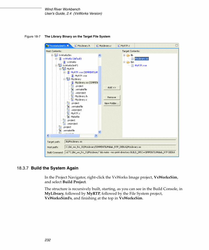
Wind River WorkbenchUser’s Guide, 2.4 (VxWorks Version)
232
18.3.7 Build the System Again
In the Project Navigator, right-click the VxWorks Image project, VxWorksSim, and select Build Project.
The structure is recursively built, starting, as you can see in the Build Console, in MyLibrary, followed by MyRTP, followed by the File System project, VxWorksSimFs, and finishing at the top in VxWorksSim.
Figure 18-7 The Library Binary on the Target File System

18 RTPs and Shared Libraries from Host to Target18.3 A VxWorks Shared Library from Real-time Process to Target
233
18
18.3.8 Run the RTP with the Shared Library on the Simulator
1. In the Target Manager, right-click VxWorksSim, the connection you created under 18.2.5 Set up the Target Connection, p.224, and select Connect.
Once the connection has been established, the Kernel Shell will appear.
2. At the Kernel Shell prompt, enter:
cd "/romfs/bin"
3. Press ENTER and type:
rtpSpawn "MyRTP.vxe"
4. Press ENTER again.
The following output should appear:
MyRTP calling MyLibrary!MyLibrary called!
5. Close the Kernel Shell.

Wind River WorkbenchUser’s Guide, 2.4 (VxWorks Version)
234

235
PAR T IV
Target Management
19 Connecting to Targets .................................. 237
20 New Target Server Connections ................. 245
21 New VxWorks Simulator Connections ........ 257
22 New On-Chip Debugging Connections ...... 261

Wind River WorkbenchUser’s Guide, 2.4 (VxWorks Version)
236

237
19 Connecting to Targets
19.1 Introduction 237
19.2 The Target Manager View 238
19.3 Defining a New Connection 238
19.4 The Registry 239
19.5 Establishing a Connection 242
19.6 Connect to the Target 242
19.1 Introduction
A target connection manages communication between the Workbench host tools and the target system. A connection must be configured and established before host tools can interact with the target.
All host-side connection configuration work and connection-related activity is done in the Target Manager view. Connections are registered and made accessible to users by the Wind River Registry.
This chapter describes ways to configure, start, and manage target connections in the Target Manager view. For detailed information Target Server and Registry, see the tgtsvr and wtxregd API reference entries (see Help > Help Contents > Wind River Documentation > References > Host APIand Command References > Wind River Host Tools API Reference).

Wind River WorkbenchUser’s Guide, 2.4
238
19.2 The Target Manager View
A connection to a Target Server, a VxWorks Simulator, an Instruction Set Simulator (ISS), or an on-chip debugging device (OCD) such as Wind River ICE and Wind River Probe must be defined and established before tools can communicate with a target system.
All host-side connection configuration work and connection-related activity is done in the Target Manager view. The target side (required for Target Server and VxWorks Simulator connections) is configured in the Kernel Editor (see 5.5.1 The Kernel Editor, p.85).
By default, the Target Manager view is on a tab at the bottom-left of Workbench. It is available in the Application Development perspective and in the Device Debug perspective. If the view is not visible, choose Window > Show View > Target Manager (or, if it is not listed there, Window > Show View > Other).
The most import tasks in the Target Manager view are:
■ defining new connections■ connecting to targets■ disconnecting from targets
Once you have connected to a target, more commands are enabled on the right-click context menu (see also 23. Launching Programs).
19.3 Defining a New Connection
All connections types are defined from the Target Manager view (see 19.2 The Target Manager View, p.238).
To open the New Connection wizard, use the appropriate toolbar icon or right-click in the Target Manager and select New > Connection.
The first thing the New Connection wizard asks you to do is to select one of the following connection types:
■ Wind River ICE
See 22.1 Defining a New Wind River ICE SX Connection, p.261.
■ Wind River ISS
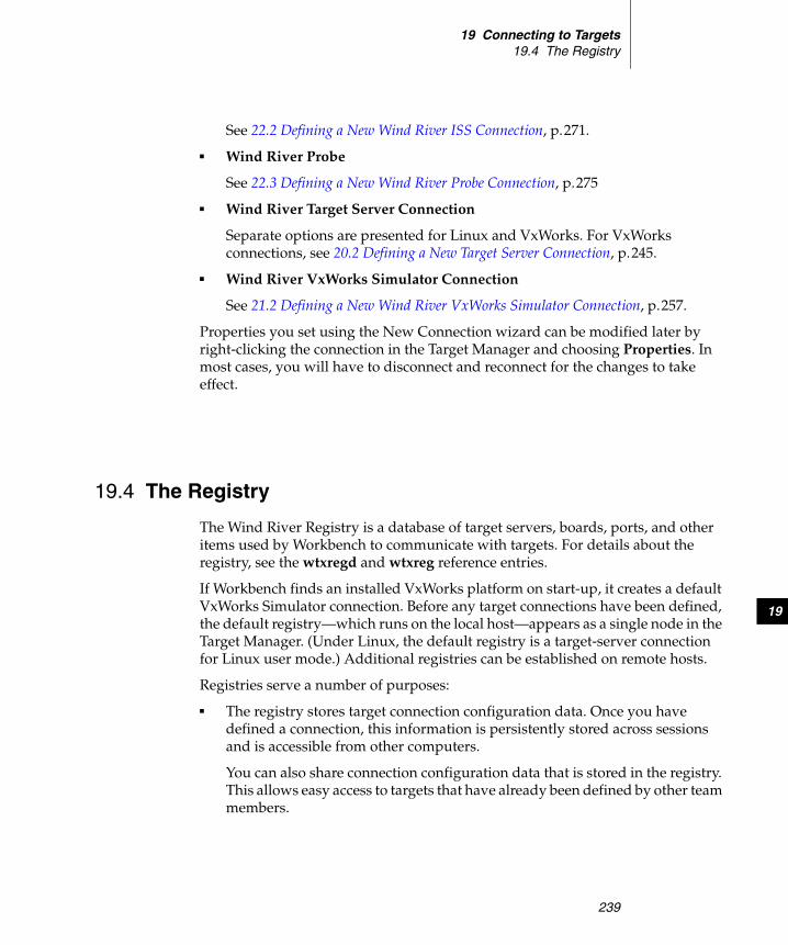
19 Connecting to Targets19.4 The Registry
239
19
See 22.2 Defining a New Wind River ISS Connection, p.271.
■ Wind River Probe
See 22.3 Defining a New Wind River Probe Connection, p.275
■ Wind River Target Server Connection
Separate options are presented for Linux and VxWorks. For VxWorks connections, see 20.2 Defining a New Target Server Connection, p.245.
■ Wind River VxWorks Simulator Connection
See 21.2 Defining a New Wind River VxWorks Simulator Connection, p.257.
Properties you set using the New Connection wizard can be modified later by right-clicking the connection in the Target Manager and choosing Properties. In most cases, you will have to disconnect and reconnect for the changes to take effect.
19.4 The Registry
The Wind River Registry is a database of target servers, boards, ports, and other items used by Workbench to communicate with targets. For details about the registry, see the wtxregd and wtxreg reference entries.
If Workbench finds an installed VxWorks platform on start-up, it creates a default VxWorks Simulator connection. Before any target connections have been defined, the default registry—which runs on the local host—appears as a single node in the Target Manager. (Under Linux, the default registry is a target-server connection for Linux user mode.) Additional registries can be established on remote hosts.
Registries serve a number of purposes:
■ The registry stores target connection configuration data. Once you have defined a connection, this information is persistently stored across sessions and is accessible from other computers.
You can also share connection configuration data that is stored in the registry. This allows easy access to targets that have already been defined by other team members.

Wind River WorkbenchUser’s Guide, 2.4
240
■ The registry keeps track of the currently running target servers and administrates access to them.
■ Workbench needs the registry to detect and launch target servers.
If Workbench does not detect a running default registry at start-up, it launches one. After quitting, the registry is kept running in case it is needed by other tools. You do not ever need to terminate the registry. If you do terminate the registry, it stores its internal data in a file that has to be writable on relaunching Workbench. Please refer to 19.4.2 Registry Data Storage, p.241, for information on the location of this file.
19.4.1 Remote Registries
If you have multiple target boards being used by multiple users, it makes sense to maintain connection data in a central place (the remote registry) that is accessible to everybody on the team. This saves everyone from having to remember communications parameters such as IP addresses, etc. for every board that they might need to use.
Creating a Remote Registry
You might want to create a new master registry on a networked remote host that is accessible to everybody. To do so:
1. Workbench needs to be installed and the registry needs to be running on the remote host. The easiest way to launch the registry is to start and quit Workbench. However, you can also launch the wtxregd program from the command line. (For more information about wtxregd, see Help > Help Contents > Wind River Documentation > References > Host API and Command References > Wind River Host Tools API Reference.)
2. Right-click in the Target Manager, (see 19.2 The Target Manager View, p.238), then select New > Registry from the context menu.
3. In the dialog that appears, enter either the host name or the IP address of the remote host.
NOTE: Having connection configuration data does not yet mean that the target is actually connected.

19 Connecting to Targets19.4 The Registry
241
19
Workbench immediately attempts to connect to the remote registry. If the host is invalid, or if no registry is identified on the remote host, this information is displayed in the Target Manager.
19.4.2 Registry Data Storage
If you shut down the registry, its internal data is written to the file installDir/.wind/wtxregd.hostname. If this file is not writable on launch, the registry attempts to write to /var/tmp/wtxregd.hostname instead. If this file is also not writable, the registry cannot start and an error message appears.
19.4.3 The Registry and Product Updates
Because other tools use the registry, it is not automatically shut down when you quit Workbench. Before updating or uninstalling Workbench (or other products that use the registry), it is advisable to shut down the registry so that the new one starts with a fresh database. To shut down the registry:
■ On Windows, right-click the registry icon in the system tray, and choose Shutdown.
■ On Linux and UNIX, execute wtxregd stop, or manually kill the wtxregd process.
If you want to migrate your existing registry database and all of your existing connection configurations to the new version, make a backup of the registry data file (see 19.4.2 Registry Data Storage, p.241) and copy it to the corresponding new product installation location.
19.4.4 Changing the Default Registry
Normally, the default registry runs on the local computer. You can change this if you want to force a default remote registry (see 19.4.1 Remote Registries, p.240). To do this on Linux and UNIX, modify the WIND_REGISTRY environment variable. To do this on Windows, under the Windows Registry HKEY_LOCAL_MACHINE node, modify the field Software\Wind River Systems\Wtx\N.N\WIND_REGISTRY.

Wind River WorkbenchUser’s Guide, 2.4
242
19.5 Establishing a Connection
Once you have created your application projects and defined connections, you will want to run, test, and debug the projects on your target or simulator. To do this, you first need to connect to the target.
19.5.1 Assumptions
■ You are using a simulator (VxWorks Simulator or the on-chip debugging simulator, ISS), or you are using a target board and your hardware connections are set up and running.
■ If you are using a target board (not a simulator), you have correctly configured your FTP service as described in 3. Setting Up Your Hardware and in the Wind River ICE for Wind River Workbench Hardware Reference and Wind River Probe for Wind River Workbench Hardware Reference.
■ You have defined one or more host-target connections as described in 20. New Target Server Connections, 21. New VxWorks Simulator Connections, and 22. New On-Chip Debugging Connections.
19.6 Connect to the Target
The first step in running an application on the target is to establish a connection to that target.
Connect to and disconnect from targets in the Target Manager (see 19.2 The Target Manager View, p.238) by selecting a connection node and then using the appropriate toolbar icon, or by right-clicking and selecting Connect.
Once the connection has been established:
■ If the connection is to a simulator, the Kernel Shell appears (see 19.6.1 The Kernel Shell, p.243, for more information).
■ On Windows, a registry icon appears (if it is not there already) in the Windows system tray (the area at the right of the Windows taskbar) to indicate the registry is running (see also 19.4 The Registry, p.239).
■ In the Target Manager:

19 Connecting to Targets19.6 Connect to the Target
243
19
– A blue check mark is superimposed on the top-left corner of the connection node, the node is labeled ConnectionName [connected], and new nodes appear under the connection node.
– A subnode appears under the connection node. This node’s label identifies the connection type and the kernel. The node’s right-click context menu offers a subset of the connection node’s context menu (restricted to the most commonly used commands) as well as the Kernel Objects command. The Kernel Objects command populates and opens the Kernel Objects tab (by default located behind the Target Manager).
– A number of additional subnodes appear. These are described in Table 19-1. Please refer to the Wind River Workbench User Interface Reference: Target Manager View for a full list of the icons that you might see in the Target Manager.
19.6.1 The Kernel Shell
The Kernel Shell1 that appears when you establish a connection displays output generated by applications running on the kernel.
If you are using a VxWorks Simulator connection, shell components are included in the kernel by default and the Kernel Shell also provides a prompt and accepts
Table 19-1 VxWorks Connections
Node Description
Real Time Processes When you run RTPs, they will appear as subnodes under this node.
Kernel Tasks When the connection is initially established, you see the VxWorks tasks. When you download and run DKMs, they will appear as additional subnodes under this node.
VxWorks location The kernel node and its host location. A superimposed red S at the top-right of the icon indicates that symbol information has been downloaded.
1. In versions of VxWorks prior to 6.0, the Kernel Shell was called the Target Shell. The new name reflects the fact that the target-resident shell runs in the kernel and not in a process.

Wind River WorkbenchUser’s Guide, 2.4
244
input like the Host Shell (see the VxWorks Command-Line User’s Guide). If you are using a real board connection, the kernel shell does not provide an input prompt by default; you can, however, include the necessary components in the VxWorks kernel (see 5.5 Configuring Kernel Components, p.84 as well as the VxWorks Kernel Programmer’s Guide and the VxWorks Application Programmer’s Guide).
For the most part, the Kernel Shell works the same as the Host Shell. For detailed information about the Host Shell see the VxWorks Command-Line User’s Guide. For information about the differences between the Host and Kernel shells, see the VxWorks API Reference entries for dbgLib, shellLib, and usrLib.

245
20New Target Server
Connections
20.1 Introduction 245
20.2 Defining a New Target Server Connection 245
20.3 Kernel Configuration 255
20.1 Introduction
Target Server connections are defined in the Target Manager view (see 19. Connecting to Targets).
20.2 Defining a New Target Server Connection
To open the New Connection wizard, right-click in the Target Manager, then select New > Connection.
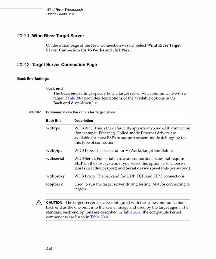
Wind River WorkbenchUser’s Guide, 2.4
246
20.2.1 Wind River Target Server
On the initial page of the New Connection wizard, select Wind River Target Server Connection for VxWorks and click Next.
20.2.2 Target Server Connection Page
Back End Settings
Back endThe Back end settings specify how a target server will communicate with a target. Table 20-1 provides descriptions of the available options in the Back end drop-down list.
Table 20-1 Communications Back Ends for Target Server
Back End Description
wdbrpc WDB RPC. This is the default. It supports any kind of IP connection (for example, Ethernet). Polled-mode Ethernet drivers are available for most BSPs to support system-mode debugging for this type of connection.
wdbpipe WDB Pipe. The back end for VxWorks target simulators.
wdbserial WDB Serial. For serial hardware connections; does not require SLIP on the host system. If you select this option, also choose a Host serial device (port) and Serial device speed (bits per second).
wdbproxy WDB Proxy. The backend for UDP, TCP, and TIPC connections.
loopback Used to run the target server during testing. Not for connecting to targets.
! CAUTION: The target server must be configured with the same communication back end as the one built into the kernel image and used by the target agent. The standard back end options are described in Table 20-1; the compatible kernel components are listed in Table 20-4.
20 New Target Server Connections20.2 Defining a New Target Server Connection
247
20
CPUWorkbench can correctly identify the target CPU. In rare cases, a close variant might be misidentified, so you can manually set the CPU here.
Name/IP addressThe Name/IP Address field specifies the network name or the IP address of the target hardware for networked targets. If you are using a serial port, enter either COM1 or COM2.
Kernel Image and Symbols
The Kernel Image and Symbols properties relate to a copy of the target kernel that resides on the host.
File path from target (if available)Select this option to search for an image of the software running on the target using the target path.
FileIf the run-time image file is not in the same location on the host that is configured into the target (or if host and target have different views of the file system), select this option and use the adjacent text box to specify the host location of the kernel image.
For example, if you are using a target programmed with a vxWorks_rom.hex, vxWorks_romCompressed.hex, or any other on-board VxWorks image, you must use this option to identify the kernel file location; otherwise the target server will not be able to identify the target symbols.
! CAUTION: Do not choose the TIPC WDB Proxy connection type unless you have included the TIPC network stack (INCLUDE_TIPC_ONLY) component in your VxWorks Image Project.
For more information about finding components to include in your VxWorks Image Project, see Wind River Workbench User Interface Reference: Kernel Editor View.
For more information about TIPC, see Wind River TIPC for VxWorks 6 Programmer’s Guide: Building VxWorks to Include Wind River TIPC.

Wind River WorkbenchUser’s Guide, 2.4
248
Advanced Target Server Options
Please see the tgtsvr reference entry in the online API reference and the VxWorks Programmer’s Guide for more detailed information about target server options in the Target Manager, as well as on additional available options.
Options
These options are passed to the tgtsvr program on the command line. Enter these options manually, or use the Edit button for GUI-assisted editing.
Advanced Target Server Options Dialog
The properties in the Advanced Target Server Options dialog that you open with Edit on the main wizard page are subdivided into three tabbed groups: Common, Memory, and Logging.
The Common Tab
Target Server File System
The Target Server File System (TSFS) is a full-featured VxWorks file system that provides target access to files located on the host system. It is used by the Wind River System Viewer. It also provides the most convenient way to boot a target over a serial connection. Although somewhat slow, it is simple and easy to use.
A target can access files on the host it is booted from, if booted via FTP or rsh. However, if the target is booted from a remote host, you can use the TSFS as a simple method to access files on the local host.
The TSFS is also the default method used by the System Viewer for uploading event data from the target. The TSFS should therefore be enabled and writable (default) when using the System Viewer.
Root
If the Enable File System check box is selected, you have to identify the root of the host file system that will be made visible to target processes using the TSFS. By default, this is the Workspace root directory. If you use the TSFS for
! CAUTION: To use the TSFS, you must include the WDB target server file system component when you build the kernel image. See 20.3 Kernel Configuration, p.255, below, and the VxWorks Kernel Application Programmer’s Guide for more details.
20 New Target Server Connections20.2 Defining a New Target Server Connection
249
20
booting a target, it is recommended that you use the default root directory. If you do not use TSFS, you must use the Kernel Image and Symbols configuration options to specify the location of the kernel image (see Kernel Image and Symbols, p.247).
Make Target Server File System writable
To use the Wind River System Viewer, you must select this check box to allow uploading of event data from the target. Because this also allows other users to access your host file system, you may wish to set the TSFS option for your target server to read-only when you are not using the System Viewer.
Timeout Options
Specify allowable spawn time (in seconds) for kernel tasks and RTPs, time (in seconds) to wait for a response from the agent running on the target system, how often to retry, and at what intervals.
The Memory Tab
Memory Cache Size
To avoid excessive data-transfer transactions with the target, the target server maintains a cache on the host system. By default, this cache can grow up to a size of 1 MB.
A larger maximum cache size may be desirable if the memory pool used by host tools on the target is large, because transactions on memory outside the cache are far slower.
The Logging Tab
Options on the Logging tab are used mainly for troubleshooting by Customer Support.
A maximum size can be specified for each enabled log file. Files are rewritten from the beginning when the maximum size is reached. If a file exists, it is deleted when the target server restarts (for example, after a reboot).
For the WTX (Wind River Tool Exchange) log file, you can specify a filter, a regular expression that limits the type of information logged. In the absence of a filter, the log captures all WTX communication between host and target. Use this option in consultation with Customer Support.

Wind River WorkbenchUser’s Guide, 2.4
250
20.2.3 Object Path Mappings Page
Object Path Mappings have two functions:
■ To allow the debugger to find symbol files for processes created on the target by creating a correspondence between a path on the target and the appropriate path on the host.
■ To calculate target paths for processes that you want to launch by browsing to them with a host file-system browser.
By default, the debug server attempts to load all of a module’s symbols each time a module is loaded. In the rare cases where you want to download a module or start a process without loading the symbol file, uncheck Load module symbols to debug server automatically if possible.
The simplest way to create Object Path Mappings for a module that does not have symbols yet is to download the output file (or run the executable) manually. In the Target Manager, right-click the file or executable and select Load Symbols to Debug Server. From the Load Symbols dialog, select create path mappings based on selection and click OK. Object path mappings are created automatically, so that after the next disconnect/reconnect sequence the symbols will be found.
Pathname Prefix Mappings
This maps target path prefixes to host paths. Always use full host paths, not relative paths.
For example, mapping /tgtsvr/ to C:\workspace\ tells the debugger that files accessible under /tgtsvr/ on the target can be found under C:\workspace\ on the host.
If you launch the process host:/usr/hello.vxe on your target, Workbench needs to know what host:/ corresponds to; in other words, where it can find the hello.vxe ELF file in the host file system. With an object path mapping of host:/ to C:\WindRiver\, Workbench knows that the host path to the file is C:\WindRiver\usr\hello.vxe.
In most cases Workbench provides correct defaults. If necessary, click Add to add new mappings, or select existing mappings and click Edit to modify existing mappings. The supplied default mappings are not editable.

20 New Target Server Connections20.2 Defining a New Target Server Connection
251
20
Reverse Mapping
Sometimes host paths must be mapped to target paths. For example, if you want to browse to the process C:\WindRiver\usr\hello.vxe and launch it on the target, Workbench needs to know that the correct target path for this process is host:/usr/hello.vxe.
Path Mappings for Working with Remote Hosts
You may need to edit object path mappings if your target boots from a remote host or if your target server runs on a remote host.
Running the target server on a remote host (using a remote registry; see 19.4.1 Remote Registries, p.240 for details) allows you to:
■ Access targets using a serial line wdb connection even if the targets are physically connected to a remote host.
■ Have different IP subnets for the targets in a lab and the client running Workbench, with the target server being the intermediary to translate between the separate subnets.
In this discussion, the target is the VxWorks target, the host is the remote registry host that the target server is running on, and the client is the system on which Workbench is running.
Prerequisites
To allow Workbench to access targets attached to a remote host, two prerequisites must be met:
1. The VxWorks image must be visible to the target (for booting), the host (for the target server), and the client (for the debugger and the host shell).
2. A file system must be shared between the target and client for running RTPs.
Example: Adding New Path Mappings
When the target server is running on a host that can see the same (networked) file system that the client can, you do not need to adjust your object path mappings. The remote target server connections can be used exactly like local connections.
However, when the remote host and the client see different file systems, you need to create new path mappings to tell the debugger where it can find the files seen by the target server. In this case, the path to the kernel image is entered as seen on the remote host; path mappings must be added to tell the debugger where these paths are on the client.
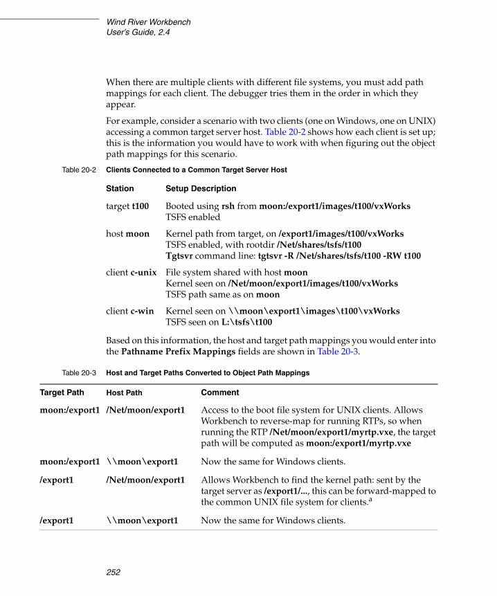
Wind River WorkbenchUser’s Guide, 2.4
252
When there are multiple clients with different file systems, you must add path mappings for each client. The debugger tries them in the order in which they appear.
For example, consider a scenario with two clients (one on Windows, one on UNIX) accessing a common target server host. Table 20-2 shows how each client is set up; this is the information you would have to work with when figuring out the object path mappings for this scenario.
Based on this information, the host and target path mappings you would enter into the Pathname Prefix Mappings fields are shown in Table 20-3.
Table 20-2 Clients Connected to a Common Target Server Host
Station Setup Description
target t100 Booted using rsh from moon:/export1/images/t100/vxWorksTSFS enabled
host moon Kernel path from target, on /export1/images/t100/vxWorksTSFS enabled, with rootdir /Net/shares/tsfs/t100Tgtsvr command line: tgtsvr -R /Net/shares/tsfs/t100 -RW t100
client c-unix File system shared with host moonKernel seen on /Net/moon/export1/images/t100/vxWorksTSFS path same as on moon
client c-win Kernel seen on \\moon\export1\images\t100\vxWorksTSFS seen on L:\tsfs\t100
Table 20-3 Host and Target Paths Converted to Object Path Mappings
Target Path Host Path Comment
moon:/export1 /Net/moon/export1 Access to the boot file system for UNIX clients. Allows Workbench to reverse-map for running RTPs, so when running the RTP /Net/moon/export1/myrtp.vxe, the target path will be computed as moon:/export1/myrtp.vxe
moon:/export1 \\moon\export1 Now the same for Windows clients.
/export1 /Net/moon/export1 Allows Workbench to find the kernel path: sent by the target server as /export1/..., this can be forward-mapped to the common UNIX file system for clients.a
/export1 \\moon\export1 Now the same for Windows clients.

20 New Target Server Connections20.2 Defining a New Target Server Connection
253
20
If you do not run RTPs, only the mappings for the kernel image are required (shown in the third and fourth rows of Table 20-3). None of the other mappings are necessary, since a file system is not needed for debugging kernel modules.
Basename Mappings
Use square brackets to enclose each mapping of target file basenames (left element) to host file basenames (right element), separated by a semi-colon (;). Mapping pairs (in square brackets) are separated by commas. You can use an asterisk (*) as a wildcard.
For example, if debug versions of files are identified by the extension *.unstripped, the mapping [*;*.unstripped] will ensure that the debugger loads yourApp.vxe.unstripped when yourApp.vxe is launched on the target.
20.2.4 Target State Refresh Page
Since retrieving status information from the target leads to considerable target traffic, this page allows you to configure how often and under what conditions the information displayed in the Target Manager is refreshed.
These settings can be changed later by right-clicking the target connection and selecting Refresh Properties.
Available CPU(s) on Target Board
Workbench can correctly identify the target CPU. In rare cases, a close variant might be misidentified, so you can manually set the CPU here.
/tgtsvr /Net/shares/tsfs/t100 Allow reverse-mapping of the tgtsvr file system for UNIX hosts.
/tgtsvr L:\tsfs\t100 Now the same for Windows hosts.
a. This mapping may be used only for forward-mapping the kernel image, so it must be listed after the previous mappings, which are used for reverse-mapping as well.
Table 20-3 Host and Target Paths Converted to Object Path Mappings (cont’d)

Wind River WorkbenchUser’s Guide, 2.4
254
Initial Target State Query and Settings
Specify whether Workbench should query the target on connect, on stopped events, and/or on running events. You can select all options if you like.
Target State Refresh Settings
Specify whether Workbench should refresh the target state only when you manually choose to do so, or if (and how often) the display should be refreshed automatically.
Listen to execution context life-cycle events
Specify whether Workbench should listen for life-cycle events or not.
20.2.5 Connection Summary Page
This page proposes a unique Connection name, which you can modify, and displays a Summary of name and path mappings for review. To modify these mappings, click Back.
SharedThis option, which is available only for certain connection types, serves a dual purpose:
■ When you define a target connection configuration, this connection is normally visible only for your user ID. If you define it as Shared, other users can also see the configuration in your registry, provided that they connect to your registry (by adding it as a remote registry on their computer; see 19.4.1 Remote Registries, p.240).
■ Normally, when you terminate a target connection, the target server (and simulator) are killed because they are no longer needed. In a connection that is flagged as Shared, however, they are left running so that other users can connect to them. In other words, you can flag a connection as shared if you want to keep the target server (and simulator) running after you disconnect or exit Workbench.
Immediately connect to target if possibleIf you do not want to connect to the target immediately, you can connect to the target later using one of the ways described in 25. Debugging Projects. If you

20 New Target Server Connections20.3 Kernel Configuration
255
20
have applications ready to run using the connection(s) you just created, please see 23. Launching Programs.
20.3 Kernel Configuration
Once you have defined a Target Server (or VxWorks Simulator) connection, you may have to configure the kernel communication. The default configuration, however, will normally work fine for getting started.
The target server and the simulator communicate with the target system through the target agent. To communicate with the target agent, the target server uses a communication back end that has to be configured for the same communication protocol and transport layer as the target agent on the kernel.
When you create Target Server or VxWorks Simulator connections, you define host back end communication in the Kernel Editor. For more information about this topic, see 5.5.1 The Kernel Editor, p.85.
Table 20-4 shows an overview of target server back ends and the kernel components that provide the required target-agent communication interface.
Figure 20-1 shows where to find these kernel components in the Kernel Editor.
Table 20-4 Communications Back Ends for Target Server and Compatible Kernel Components
Back End Compatible Kernel Component
wdbrpc WDB END driver connection or WDB network connection
wdbpipe WDB simulator pipe connection
wdbserial WDB serial connection
wdbproxy WDB network connection (for UDP/TCP) or TIPC network stack (for TIPC)
loopback Not applicable, see Table 20-1.

Wind River WorkbenchUser’s Guide, 2.4
256
These and other communication-related kernel components are described in detail in the VxWorks Programmer’s Guide: Kernel Images, Components, and Configuration.
Figure 20-1 Kernel Editor Showing WDB Connection Components

257
21New VxWorks Simulator
Connections
21.1 Introduction 257
21.2 Defining a New Wind River VxWorks Simulator Connection 257
21.1 Introduction
The Wind River VxWorks Simulator allows you to simulate a connection to a standard or customized version of a VxWorks 6 kernel.
21.2 Defining a New Wind River VxWorks Simulator Connection
For VxWorks Simulator-specific information going beyond this description, please see the Wind River VxWorks Simulator User’s Guide.
Target Server connections are defined in the Target Manager view (see 19.2 The Target Manager View, p.238).
To open the New Connection wizard, right-click in the Target Manager and choose New > Connection.

Wind River WorkbenchUser’s Guide, 2.4 (VxWorks Version)
258
On the initial page of the New Connection wizard, select Wind River VxWorks Simulator Connection and click Next.
21.2.1 VxWorks Boot Parameters Page
Standard Simulator (Default)Select this option to create a simulated connection to a standard VxWorks kernel.
Custom SimulatorSelect this option if you are using a customized VxWorks kernel.
VxWorks Kernel ImageThis field is enabled only if you select Custom Simulator. Navigate to the location of your customized kernel image.
Processor NumberYour system is automatically configured to run multiple simulators. Workbench assigns each simulator a unique positive number, known as the Processor number.
Advanced Boot ParametersPlease see the Wind River VxWorks Simulator User’s Guide for information on the vxsim command-line options that can be set in this dialog.
21.2.2 VxSim Memory Options Page
These options allow you to manage your memory resources. Please see the Wind River VxWorks Simulator User’s Guide for details.
21.2.3 VxWorks Simulator Miscellaneous Options Page
This page offers file-system location options (see the Wind River VxWorks Simulator User’s Guide for details) and a field for entering additional command-line options that are passed as-is to vxsim.

21 New VxWorks Simulator Connections21.2 Defining a New Wind River VxWorks Simulator Connection
259
21
21.2.4 Target Server Options Page
WDB back end typeThis corresponds to the Back end, as described for the Target Server connection; see Back End Settings, p.246. The VxWorks Simulator uses the wdbpipe back end by default.
Name/IP AddressAvailable only if the wdbrpc back end is selected. Specifies the network name or IP address of the target. If you are using a serial port, enter either COM1 or COM2.
The remaining options in the wizard are the same as those outlined for the Target Server connection settings. These are described starting from Advanced Target Server Options Dialog, p.248.
If you have created a connection for a standard simulator, the default settings should work. However, if you have defined a custom simulator connection, you may have to configure the kernel-side communication, see 20.3 Kernel Configuration, p.255.
If you have applications ready to run using the connection(s) you have just created, please see 23. Launching Programs.

Wind River WorkbenchUser’s Guide, 2.4 (VxWorks Version)
260

261
22 New On-Chip
DebuggingConnections
22.1 Defining a New Wind River ICE SX Connection 261
22.2 Defining a New Wind River ISS Connection 271
22.3 Defining a New Wind River Probe Connection 275
22.1 Defining a New Wind River ICE SX Connection
Wind River ICE SX connections are defined in the Target Manager view (see 19.2 The Target Manager View, p.238).
To open a new Wind River ICE SX connection, use the following steps:
1. Right-click in the Target Manager view and select New > Connection. The New Connection Wizard appears, as shown in Figure 22-1.
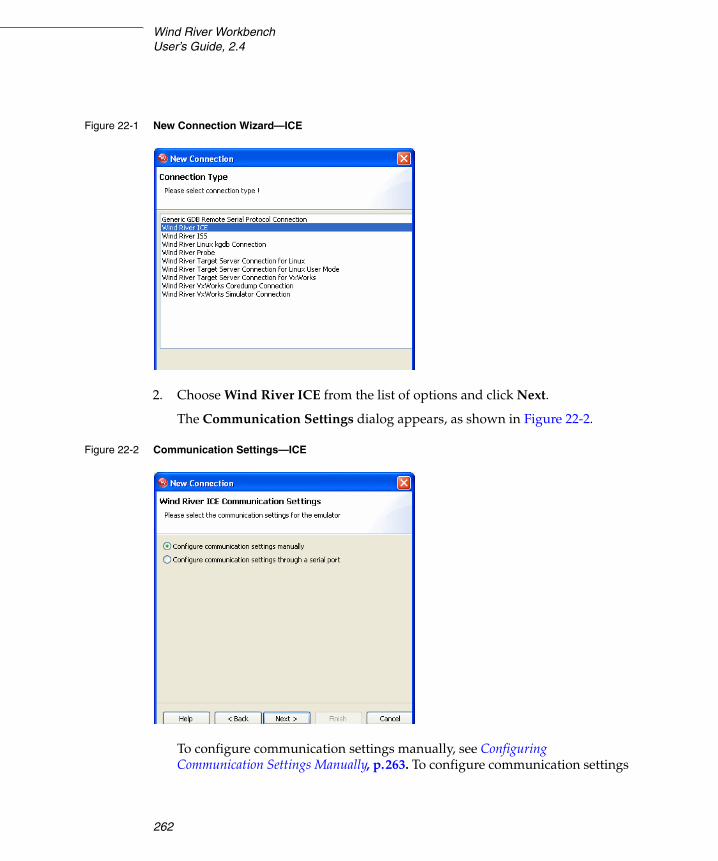
Wind River WorkbenchUser’s Guide, 2.4
262
2. Choose Wind River ICE from the list of options and click Next.
The Communication Settings dialog appears, as shown in Figure 22-2.
To configure communication settings manually, see Configuring Communication Settings Manually, p.263. To configure communication settings
Figure 22-1 New Connection Wizard—ICE
Figure 22-2 Communication Settings—ICE

22 New On-Chip Debugging Connections22.1 Defining a New Wind River ICE SX Connection
263
22
through a serial port, see Configuring Communication Settings Through a Serial Port, p.265.
Configuring Communication Settings Manually
3. Check the Configure Communication Settings Manually box and click Next.
The Settings dialog appears, as shown in Figure 22-3.
4. In the Designators area, click Select to choose from a list of available target processors.
If you are using multiple processors, or if you have multiple devices (such as field-programmable gate arrays or application-specific integrated circuits) on your JTAG scan chain, specify a board file in the Board File field. If you are only connecting a single processor, you do not need a board file, and you can ignore the Board File field.
Either choice will populate the field below the Board File field with a summary description of your board.
5. In the Communications area, fill in the IP Address field with the IP address you have assigned to your ICE unit.
Figure 22-3 shows the Settings dialog with values for a PPC750FX board.
NOTE: If you choose this option you will need to know either the network name of the emulator or its IP address. For information on assigning these values, see the Wind River ICE SX for Wind River Workbench Hardware Reference: Configuring the Wind River ICE SX for Network Operation.

Wind River WorkbenchUser’s Guide, 2.4
264
6. When you have entered the correct processor or board file and IP address, click Next.
Figure 22-3 Settings Dialog

22 New On-Chip Debugging Connections22.1 Defining a New Wind River ICE SX Connection
265
22
The Target Operating System Settings dialog appears. Proceed to Step 7.
Configuring Communication Settings Through a Serial Port
If you choose to make your connection using the serial port, make sure that a serial cable is connected between Wind River ICE SX and your host computer.
a. Check the Configure Communication Settings Through a Serial Port box and click Next. The Settings dialog appears, as shown in Figure 22-4.
b. Use this dialog to select the serial port you want to connect to, and set a timeout value in seconds. Communication settings such as the ICE’s dynamically assigned IP address and other settings will be retrieved and displayed automatically, as shown in Figure 22-5.
NOTE: A direct serial cable is required to create your connection this way. If you do not have a direct serial connection between your host and emulator, you must configure your ICE settings manually.
Figure 22-4 Serial Settings

Wind River WorkbenchUser’s Guide, 2.4
266
The retrieved settings can also be modified; that is, you can reconfigure the Wind River ICE SX communication settings using a serial connection. To do this, check the Modify checkbox.
If you have downloaded a TOS (Target Operating System) to the board, click into the TOS plugin column, select the operating system from the dropdown, and enter any required parameters in the next column.
c. Click Next.
The Target Operating System Settings dialog appears, as shown in Figure 22-6.
Figure 22-5 Serial Settings Summary

22 New On-Chip Debugging Connections22.1 Defining a New Wind River ICE SX Connection
267
22
7. In the Booted Target OS on selected CPU field, select the operating system that is running on your target processor. The default is None.
8. Next to the Kernel Image field, click Browse to navigate to the kernel image you wish to specify. If you selected None in the previous step, you do not need to specify a kernel image.
9. If you are using a Linux plug-in, specify the pass-through options in the Target OS Pass-Through Options field. If you are not using a Linux plug-in, skip this step.
Options are passed as pairs in the format name=’value’. Separate options with a comma. The following options are available:
■ notasklist=’1’ : Never fetch process list.
■ noautomodules=’1’ : Do not plant internal breakpoints to do automatic kernel module load/unload detection. When this option is specified, you must manually refresh to see an updated module list.
Figure 22-6 Target OS Settings

Wind River WorkbenchUser’s Guide, 2.4
268
■ noloadcheckuntilhit=’1’ : Do not issue gophers until a hardware breakpoint is used to detect kernel load triggers. This option is for “sensitive” boards that do not accept access until the kernel loads and sets up memory mapping.
■ loaddetectloc=’symbol or address’ : Set the hardware breakpoint used to detect kernel load at symbol (for example, loaddetectloc=start_kernel) or address (for example, loaddetectloc=0x1000). If you do not specify a symbol or address, Workbench uses a default. For most architectures the default is start_kernel; for PowerPC targets, the default is 0x0.
10. Click Next.
The Object Path Mappings dialog appears, as shown in Figure 22-7.
Use the Object Path Mappings dialog to specify how files in the target file system are visible in the host file system.
11. To add a host or target path, click Add... and type the path in the dialog that appears.
Figure 22-7 Object Path Mappings

22 New On-Chip Debugging Connections22.1 Defining a New Wind River ICE SX Connection
269
22
12. Click Next.
The Target State Refresh dialog appears, as shown in Figure 22-8.
Use the Target State Refresh dialog to configure the target state query and target state refresh settings on your target processor.
13. Click Next.
The Connection Summary dialog appears, as shown in Figure 22-9. Inspect the displayed values to make sure they are correct.
Figure 22-8 Target State Refresh
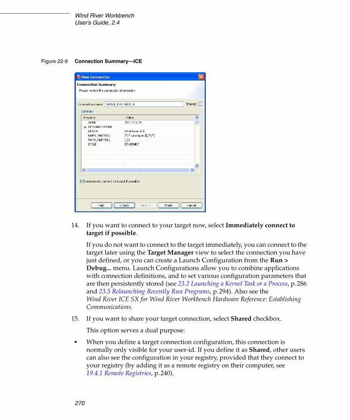
Wind River WorkbenchUser’s Guide, 2.4
270
14. If you want to connect to your target now, select Immediately connect to target if possible.
If you do not want to connect to the target immediately, you can connect to the target later using the Target Manager view to select the connection you have just defined, or you can create a Launch Configuration from the Run > Debug... menu. Launch Configurations allow you to combine applications with connection definitions, and to set various configuration parameters that are then persistently stored (see 23.2 Launching a Kernel Task or a Process, p.286 and 23.5 Relaunching Recently Run Programs, p.294). Also see the Wind River ICE SX for Wind River Workbench Hardware Reference: Establishing Communications.
15. If you want to share your target connection, select Shared checkbox.
This option serves a dual purpose:
■ When you define a target connection configuration, this connection is normally only visible for your user-id. If you define it as Shared, other users can also see the configuration in your registry, provided that they connect to your registry (by adding it as a remote registry on their computer, see 19.4.1 Remote Registries, p.240).
Figure 22-9 Connection Summary—ICE

22 New On-Chip Debugging Connections22.2 Defining a New Wind River ISS Connection
271
22
■ Normally, when you disconnect a target connection, the target server (and simulator) are killed because they are no longer needed. In a connection that is flagged as Shared, however, they are left running so that other users can connect to them. In other words, you can flag a connection as shared if you want to keep the target server (and simulator) running after you disconnect or exit Workbench.
16. Click Finish.
Your connection is now visible in the Target Manager view.
22.2 Defining a New Wind River ISS Connection
For more information on the Wind River Instruction Set Simulator (ISS), please see the Wind River Workbench On-Chip Debugging Guide: Using the Instruction Set Simulator and the Wind River Workbench Compiler manuals.
ISS connections are defined in the Target Manager view (see 19.2 The Target Manager View, p.238).
To define a Wind River ISS connection, use the following steps:
1. Right-click in the Target Manager view and select New > Connection.
The New Connection Wizard appears, as shown in Figure 22-10.
NOTE: For Wind River ICE SX-specific information going beyond this chapter, including troubleshooting information, see the Wind River ICE SX for Wind River Workbench Hardware Reference and the Wind River Workbench On-Chip Debugging Guide.
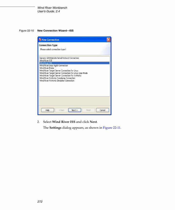
Wind River WorkbenchUser’s Guide, 2.4
272
2. Select Wind River ISS and click Next.
The Settings dialog appears, as shown in Figure 22-11.
Figure 22-10 New Connection Wizard—ISS

22 New On-Chip Debugging Connections22.2 Defining a New Wind River ISS Connection
273
22
3. Select a Processor (to simulate single-core debugging) or a Board file (to simulate multi-core debugging.)
This populates the list below the Board file field with a summary description of the board.
If you are simulating a board with multiple cores, the list will display a row for each. You can choose which cores you want to debug by selecting the checkbox in the first column of each row.
The second column displays the unique designator used to identify each core.
4. Click Next.
The wizard next passes through three screens (Target Operating System Settings, Object Path Mappings, and Target State Refresh) that specify parameters on the target processor. Since this is a simulated connection and
Figure 22-11 Instruction Set Simulator Settings
NOTE: The TOS (Target Operating System) plugin and TOS parameters are not supported for the Instruction Set Simulator.

Wind River WorkbenchUser’s Guide, 2.4
274
there is no real target processor, you can ignore these screens. Click Next until the Connection Summary dialog appears, as shown in Figure 22-12.
5. Check the displayed values to make sure they are correct.
6. If you want to connect to your simulation now, select Immediately connect to target if possible.
If you do not want to connect to the simulation immediately, you can connect later using the Target Manager view to select the connection you just defined.
7. Click Finish.
Your connection is now visible in the Target Manager view.
Figure 22-12 Connection Summary—ISS

22 New On-Chip Debugging Connections22.3 Defining a New Wind River Probe Connection
275
22
22.3 Defining a New Wind River Probe Connection
To open a new Wind River Probe connection, use the following steps:
1. Right-click in the Target Manager view and choose New > Connection.
The New Connection Wizard appears, as shown in Figure 22-13.
2. Select Wind River Probe and click Next.
The Settings dialog appears, as shown in Figure 22-14.
Figure 22-13 New Connection—Probe
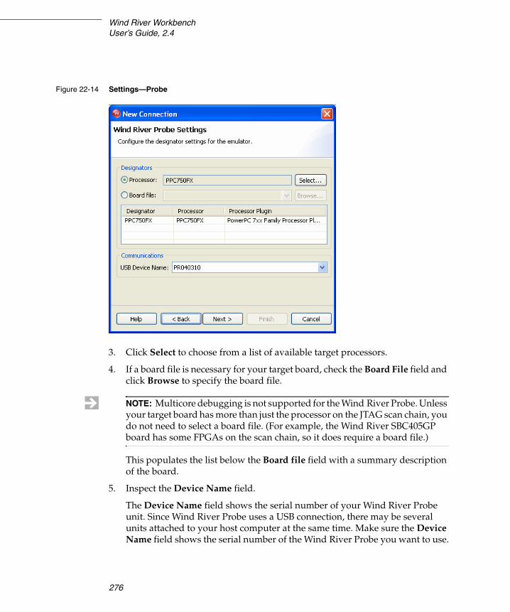
Wind River WorkbenchUser’s Guide, 2.4
276
3. Click Select to choose from a list of available target processors.
4. If a board file is necessary for your target board, check the Board File field and click Browse to specify the board file.
This populates the list below the Board file field with a summary description of the board.
5. Inspect the Device Name field.
The Device Name field shows the serial number of your Wind River Probe unit. Since Wind River Probe uses a USB connection, there may be several units attached to your host computer at the same time. Make sure the Device Name field shows the serial number of the Wind River Probe you want to use.
Figure 22-14 Settings—Probe
NOTE: Multicore debugging is not supported for the Wind River Probe. Unless your target board has more than just the processor on the JTAG scan chain, you do not need to select a board file. (For example, the Wind River SBC405GP board has some FPGAs on the scan chain, so it does require a board file.)

22 New On-Chip Debugging Connections22.3 Defining a New Wind River Probe Connection
277
22
6. Click Next.
The Target Operating System Settings dialog appears, as shown in Figure 22-15.
7. In the Booted Target OS on selected CPU field, select the operating system that is running on your target processor. The default is None.
8. Next to the Kernel Image field, click Browse to navigate to the kernel image you wish to specify. If you selected None in the previous step, you do not need to specify a kernel image.
9. If you are using a Linux plug-in, specify the pass-through options in the Target OS Pass-Through Options field. If you are not using a Linux plug-in, skip this step.
Options are passed as pairs in the format name=’value’. Separate options with a comma. The following options are available:
Figure 22-15 Target OS Settings

Wind River WorkbenchUser’s Guide, 2.4
278
■ notasklist=’1’ : Never fetch process list.
■ noautomodules=’1’ : Do not plant internal breakpoints to do automatic kernel module load/unload detection. When this option is specified, you must manually refresh to see an updated module list.
■ noloadcheckuntilhit=’1’ : Do not issue gophers until a hardware breakpoint is used to detect kernel load triggers. This option is for “sensitive” boards that do not accept access until the kernel loads and sets up memory mapping.
■ loaddetectloc=’symbol or address’ : Set the hardware breakpoint used to detect kernel load at symbol (for example, loaddetectloc=start_kernel) or address (for example, loaddetectloc=0x1000). If you do not specify a symbol or address, Workbench uses a default. For most architectures the default is start_kernel; for PowerPC targets, the default is 0x0.
10. Click Next.
The Object Path Mappings dialog appears, as shown in Figure 22-16.
Figure 22-16 Object Path Mappings

22 New On-Chip Debugging Connections22.3 Defining a New Wind River Probe Connection
279
22
Use the Object Path Mappings dialog to specify how files in the target file system are visible in the host file system.
11. To add a host or target path, click Add... and type the path in the dialog that appears.
12. Click Next.
The Target State Refresh dialog appears, as shown in Figure 22-17.
Use the Target State Refresh dialog to configure the target state query and target state refresh settings on your target processor.
13. Click Next.
The Connection Summary dialog appears, as shown in Figure 22-18. Inspect the displayed values to make sure they are correct.
Figure 22-17 Target State Refresh

Wind River WorkbenchUser’s Guide, 2.4
280
14. If you want to connect to your target now, select Immediately Connect To Target If Possible.
If you do not want to connect to the target immediately, you can connect to the target later using the Target Manager view to select the connection you have just defined, or you can create a Launch Configuration from the Run > Debug... menu.
Launch Configurations allow you to combine applications with connection definitions, and to set various configuration parameters that are then persistently stored (see 23.2 Launching a Kernel Task or a Process, p.286 and 23.5 Relaunching Recently Run Programs, p.294). Also see the Wind River Probe for Wind River Workbench Hardware Reference: Establishing Communications.
The Shared option is not available for the Wind River Probe. When you define a target connection configuration for the Wind River Probe, this connection is only visible for your user-id.
15. Click Finish.
Your connection is now visible in the Target Manager view.
Figure 22-18 Connection Summary—Probe

22 New On-Chip Debugging Connections22.3 Defining a New Wind River Probe Connection
281
22
NOTE: For Wind River Probe-specific information going beyond this description, including troubleshooting information, see the Wind River Probe for Wind River Workbench Hardware Reference and the Wind River Workbench On-Chip Debugging Guide.

Wind River WorkbenchUser’s Guide, 2.4
282

283
PART V
Debugging
23 Launching Programs .......................................... 285
24 Managing Breakpoints ....................................... 299
25 Debugging Projects ............................................ 307
26 Troubleshooting ................................................. 323

Wind River WorkbenchUser’s Guide, 2.4 (VxWorks Version)
284

285
23 Launching Programs
23.1 Introduction 285
23.2 Launching a Kernel Task or a Process 286
23.3 Reset & Download: Hardware Debugging Launches 291
23.4 Launching a Native Application 292
23.5 Relaunching Recently Run Programs 294
23.6 Using Attach-to-Target Launches 295
23.7 Suggested Workflow 298
23.1 Introduction
A launch configuration is like a named script that captures the whole process of building, connecting a target, downloading, running, and possibly attaching a debugger. Whenever you run a process, task, or program from the Project Navigator or the Target Manager, a Launch Configuration is automatically created for you. Launch configurations are stored persistently, so you can rerun your previous launches by clicking a single button, and you can share them with your team.
The same launch configuration can be executed in Run-mode and Debug-mode:
■ Run-mode connects to your target, then launches a task or process.

Wind River WorkbenchUser’s Guide, 2.4
286
■ Debug-mode is like run-mode, but in addition to connecting to your target and launching your process, it also attaches the debugger.
This chapter explains how to create, edit, and fine-tune your launch configurations to provide a tight edit-compile-debug cycle, as well as how to manually attach the debugger to tasks and processes.
For descriptions of these dialogs as well as a guide to the icons you will see in the launch configuration wizard, see the Wind River Workbench User Interface Reference: Launch Configuration Dialog.
23.2 Launching a Kernel Task or a Process
Launch configurations that run kernel tasks, RTPs, and Linux processes are very similar. Only a few options and settings differ between them.
To create a new launch configuration, select a build target in the Project Navigator then select Run > Run or Run > Debug1. The Create, manage, and run configurations dialog appears.
1. From the Configurations list, select the type of launch you want to create, then click New.
2. The Name field will display a default name based on the type of configuration you selected.
■ A new kernel task launch configuration is called noEntryPoint - moduleName - connectionName2. As soon as you select an entry point for the configuration, the name changes to entryPoint - moduleName - connectionName. If you prefer, you can type a completely new name in the Name field.
■ A new process or RTP configuration is called noExecPath - connectionName. As soon as you select an Exec Path for the configuration (when you specify the executable to run), the name changes to executable - connectionName. Or, if you prefer, you can type a completely new name in the Name field.
1. You can also create a launch configuration by right-clicking on the build target in the Project Navigator and selecting the appropriate Run or Debug command from the context menu.
2. If no target is connected, the default name is noEntryPoint - moduleName - noDownload.

23 Launching Programs23.2 Launching a Kernel Task or a Process
287
23
23.2.1 Defining the Target Connection
The default Connection to use is the target that is currently connected. If you have more than one connection defined in the Target Manager, you can select a different one from the drop-down list.
1. To change the properties of the target connection, including target server options and object path mappings, click Properties.
2. To create a new connection definition, click Add.
3. To retrieve the connection-specific properties from the target, and adjust them if necessary, click Connect.
For more information about target connections, see 20. New Target Server Connections and the Wind River Workbench User Interface Reference: Target Manager View.
23.2.2 Defining the Kernel Task or Process to Run
The settings in this section can be changed only when you are connected to a target.
Once your target is connected, you can select the Entry Point of your program from the drop-down list, click Browse next to the Exec Path on Target field and navigate to the executable to run3 (if it does not already appear), or change any of the other settings in this section.
For more information on the fields on the Main tab, see the Wind River Workbench User Interface Reference: Launch Configuration Dialog.
3. Workbench automatically maps the pathname from your host file system into a pathname that is valid on the target file system. To change the mappings, click Properties, scroll right to the Object Path Mappings tab, highlight the mapping you want to change, click Edit, then update and save your new settings.
NOTE: If your application is not built as described in 17.6 Executables that Dynamically Link to Shared Libraries, p.207, you must set the LD_LIBRARY_PATH environment variable. See that section for details.

Wind River WorkbenchUser’s Guide, 2.4
288
23.2.3 Specifying a Build Target to Download
If you want Workbench to download a particular build target each time this launch is used, specify it on the Downloads tab (this is necessary only for kernel task launches). If you highlighted a build target in the Project Navigator before opening the launch dialog, the file appears in the Downloads list automatically.
1. To modify any of the settings of the output file that appears, click Edit.
To add a file or to specify additional files to be downloaded, click Add.
In both cases, the Download dialog appears. For details about the fields in this dialog, see Wind River Workbench User Interface Reference: Launch Configuration Dialog.
2. When you are finished adjusting the settings, click OK. The new information appears in the Downloads list.
23.2.4 Specifying The Projects to Build
If you want Workbench to build a particular project or projects prior to launching this configuration, specify them on the Projects to Build tab. If you selected a build target in the Project Navigator, its project appears in the Projects to Build list automatically.
1. To add another project to the list, click Add Project, select one or more projects, then click OK.
2. To rearrange the build order in the list, select a project then click Up or Down.
3. If you do not want Workbench to build for this particular launch configuration, such as when you are working with very large projects, select all projects and select Remove to clear the list4.
NOTE: You can also create launches for kernel tasks that are already downloaded, or are resident in Flash or are part of the kernel image. Those tasks do not require an entry in the Downloads list since they do not need to be downloaded each time the configuration is run.
4. To prevent Workbench from building prior to launching any of your programs, unselect Window > Preferences > Run/Debug > Launching > Build (if required) before launching.

23 Launching Programs23.2 Launching a Kernel Task or a Process
289
23
23.2.5 Defining Debug Behavior
Break on Entry
When creating debug-mode launches, Break on entry is selected by default. Uncheck it if you want this program to run to the first breakpoint you set, rather than breaking immediately after startup.
If Break on entry is selected when the launch is run, four things happen:
■ Workbench automatically switches to the Device Debug perspective (if it is not already open).5
■ The task or process is displayed in the Debug view.
■ A temporary breakpoint is planted and appears in the Breakpoints view.
■ The program executes up to Entry Point and breaks.
Automatically Attach Spawned Kernel Tasks
For kernel task launches, select this option if you want Workbench to automatically attach spawned kernel tasks.
NOTE: Workbench is aware of relationships between projects and subprojects. So if myLib is a subproject of myProj and you choose to add myProj to the list, you cannot add myLib to the list as well because it will be built automatically when you build myProj. Adding myLib as well would be redundant and so is disabled.
When you change the list of downloaded files for kernel task launches (see Specifying a Build Target to Download, p.288) the projects containing those files are automatically added to the Projects to Build list. You should always review this list when you change the list of downloaded files.
5. From the View Management Preferences screen (Window > Preferences > Run/Debug > View Management) you can control under what circumstances Workbench switches views based on your selection.

Wind River WorkbenchUser’s Guide, 2.4
290
23.2.6 Specifying Where Workbench Should Look for Source Files
If your build target was compiled on the same host where you want to debug it, you do not need to change anything on the Source tab.
However, if the build target was compiled on a different host, and Workbench needs to find source files during debugging, it searches the locations listed on this tab in the specified order.
1. On the Sources tab, click Add to configure the source lookup path.
2. Select the type of source to add, then click OK.
3. Most choices require that you select a specific project, folder, or path. Make your selection, then click OK.
4. Click Up or Down to adjust the search order.
5. Check Search for duplicate source files on the path to have Workbench search the entire source lookup path and offer you a choice of all the files it finds that have the same filename, rather than automatically using the first file of that name it encounters.
For more information about the source locator, see 25.6 Understanding Source Lookup Path Settings, p.317 and Wind River Workbench User Interface Reference: Source Lookup Path Dialog.
23.2.7 Configuring Access Methods
Use the Common tab to specify whether this launch is local or shared, to add the launch to the Workbench toolbar favorites menus, and to indicate whether the program should be launched in the background or not.
1. By default this launch configuration is a local file available only to you. If you want to share it with others on your team, click Shared, then type or browse to the directory where you want to save the shared file.
2. If you want to be able to launch this program from the Run or Debug favorites menus (the drop-down menus on the Workbench toolbar), select Run or Debug in the Display in favorites menu box.
NOTE: If you do not specify a source lookup path, the debugger will ask for the correct source path as soon as it encounters a source it cannot find. So if you prefer, you can configure the source lookup manually as you go, rather than configuring it when creating the launch.
23 Launching Programs23.3 Reset & Download: Hardware Debugging Launches
291
23
23.2.8 Using Your Launch Configuration
When you are finished configuring the launch configuration for your program, click Apply to save your settings but leave the dialog open, click Close to save your launch configuration for later use, or click Run or Debug to launch it now.
Running Your Program
If you select Run to launch your program, the output file or executable is loaded into target memory and its name and host location appear below your target connection in the Target Manager (RTPs appear under Real-time Processes). A red S over the output file icon indicates that symbol information has been downloaded to the debugger.
Debugging Your Program
If you select Debug to launch your program, in addition to loading the output file or executable into target memory and downloading symbol information, the debugger attaches to the task or process that then appears in the Debug view. For more information about debugging your programs, see 25. Debugging Projects and the Wind River Workbench User Interface Reference: Debug View.
23.3 Reset & Download: Hardware Debugging Launches
For information about creating a Reset and Download launch configuration, see Wind River ICE SX for Wind River Workbench Hardware Reference: Establishing Communications or Wind River Probe for Wind River Workbench Hardware Reference: Establishing Communications, depending on whether you are using a Wind River ICE SX or Wind River Probe for your OCD connection.
NOTE: If no symbol information was found, right-click the module and select Load Symbols to load the symbols for your module from an alternate location.
You can also match module paths with symbol information by selecting the Create path mappings based on selection checkbox in the Load Symbols dialog.

Wind River WorkbenchUser’s Guide, 2.4
292
23.4 Launching a Native Application
1. To create a new launch configuration that will run a native application on your local host or remote host, select your application’s executable in the Project Navigator then select Run > Run. The Create, manage, and run configurations dialog appears.
2. From the Configurations list, select Native Application, then click New.
3. The default name of the new configuration is New_configuration. Type a descriptive name in the Name field.
23.4.1 Specifying the Location and Arguments for Your Application
1. To specify the location of your application’s executable file, click Browse Workspace near the Location field. The Select an application dialog opens.
2. Select the executable and click OK. The executable appears in the Location field.
3. To specify the working directory for your application, click Browse Workspace to open the Select a working directory dialog, or Browse File System to open the Browse for Folder dialog.
4. Select a working directory, then click OK. The directory appears in the Working Directory field.
5. Type the arguments your application requires into the Arguments field, or click Variables to open the Select Variable dialog. Double-click the variable you want to use, or select it and click OK to add it to the Arguments field.
23.4.2 Specifying Remote Settings
These settings are optional, and are required only if you are running your application on a remote host. For more information about working with remote hosts, see 17.9.5 Running Applications Remotely, p.216.
Command-line application’s output and input will be redirected to the standard Eclipse console unless the application is started within an external process that creates a new window, such as xterm.
1. If your application requires an interactive shell, type the program and arguments in the Remote Program field. The default for remote execution is a

23 Launching Programs23.4 Launching a Native Application
293
23
remote command like xterm -e %Application%, so a local X-server like Exceed or Cygwin X must be running.
2. If you want to use a different working directory than the one specified on the Arguments tab, type the path to the desired directory (as seen on the remote host).
23.4.3 Setting Environment Variables
These settings define the environment variable values to use when running a Java application. By default, the environment is inherited from the Eclipse run time. You may override or append to the inherited environment.
1. To set a new environment variable, or to change or extend variables from the existing environment, click New. The New Environment Variable dialog opens.
2. Type a descriptive name for the variable.
3. Type the value for the variable, or click Variables and select the desired variable, add any required arguments, then click OK.
4. To include an existing environment variable, click Select. The Select Environment Variables dialog opens.
5. Select the checkbox next to the desired variable, then click OK.
6. For each variable, choose whether to append it to the native environment or substitute it for the native environment.
23.4.4 Configuring Access Methods
Use the Common tab to specify whether this launch is local or shared, to add the launch to the Workbench toolbar favorites menus, and to indicate whether the program should be launched in the background or not.
1. By default this launch configuration is a local file available only to you. If you want to share it with others on your team, click Shared, then type or browse to the directory where you want to save the shared file.
NOTE: These settings apply to applications that run locally, not to remote applications.

Wind River WorkbenchUser’s Guide, 2.4
294
2. If you want to be able to launch this program from the Run favorites menu (the drop-down menu on the Workbench toolbar), select Run in the Display in favorites menu box.
23.4.5 Running Your Native Application
When you are finished configuring the launch configuration for your application, click Apply to save your settings but leave the dialog open, click Close to save your launch configuration for later use, or click Run to launch it now.
23.5 Relaunching Recently Run Programs
In a typical development scenario, you will run the same application many times in a single debugging session. After creating a launch configuration, you can click the Run or Debug icon or use a keyboard shortcut to run a process and attach the debugger in a few seconds.
To relaunch a recently run program:
■ Press CTRL+F11 to launch the last run-mode configuration you used, or F11 to launch the last debug-mode configuration you used.
■ Click the drop-down arrow next to the Run or Debug icon and select the configuration from the list. If you ran the configuration recently, it will appear on the menu. If you selected Run or Debug from the Display in favorites menu list (see Configuring Access Methods, p.290) it will always appear on the list, whether you have run it recently or not.

23 Launching Programs23.6 Using Attach-to-Target Launches
295
23
■ To run a configuration not listed on the favorites menu, click Run > Run or Run > Debug, then choose the configuration from the Configurations list and click Run or Debug.
23.5.1 Increasing the Size of the Launch History List
Workbench stores a history of previously launched configurations. The default length of the launch history is 10, but you can increase the history length by selecting Window > Preferences > Run/Debug > Launching and increasing the number in the Size of recently launched applications list field.
23.6 Using Attach-to-Target Launches
Workbench automatically creates Attach to Target launch configurations when you attach to an individual process or kernel task from the Target Manager. They do not actually run an application, they just connect to your target and attach the debugger to the specified task or process that already exists. These configurations are visible only in Debug mode.
Once Attach to Target launches are created, you can:
■ Review them and delete those that you no longer need.
■ Change which target connection should be used to run the process.
■ Rename your launch configurations, and if you think they are valuable, put them into your Favorites menu using the Common tab.
■ Change the mapping between source paths compiled into your objects and source paths in your workspace by editing the Source Locator information in the Sources tab.
■ Change the Projects to Build settings for the launch. This is particularly valuable for Attach to Kernel launches on the VxWorks simulator: you can disconnect your simulator, rebuild your kernel as part of the launch, and then let the launch automatically restart and reconnect the simulator. Automatically rebuilding shared libraries is another use of Build before launching.

Wind River WorkbenchUser’s Guide, 2.4
296
23.6.1 Attaching the Debugger to a Running Task or Process
To attach the debugger to a task or RTP that is already running, right-click it in the Target Manager and select:
■ Attach to Real-time Process to attach to a Real-time Process on VxWorks.
■ Attach to Kernel Task to attach to a kernel task on VxWorks.
■ Attach to Process to attach to a process on Linux.
Whenever you manually attach an individual process or task, Workbench automatically switches to the Device Debug perspective (if it is not already open) and displays the task or process in the Debug view, the debugger attaches without stopping the program, and Workbench automatically creates a corresponding Attach-to-Target launch configuration with those properties. For more information about how to use Attach-to-Target configurations, see 23.6 Using Attach-to-Target Launches, p.295.
Comparing Definitions: Running, Suspended, and Stopped Tasks
VxWorks and the Workbench Debug view both make a distinction between running, suspended, or stopped tasks, but their definitions are not identical.
NOTE: When you attach to a process or task with the same name using the same connection, Workbench automatically reuses all the settings from the previous launch.
However, Workbench creates a new launch (requiring you to reconfigure the settings) when it detects that the properties of the connection have changed: for example, if the connection was renamed, a different kernel image was used, or the target server arguments or other connection properties were changed.
One way to avoid accumulating many similar launches is to make your configuration changes in the launch itself, rather than right-clicking a process in the Target Manager and selecting Attach. That way Workbench will always have the correct settings for the process you want to run.
VxWorks Workbench Debug View Definition
Running Running Task is active, and has focus.
Suspended Running Task is waiting while another task runs.

23 Launching Programs23.6 Using Attach-to-Target Launches
297
23
23.6.2 Attaching the Debugger to the Kernel
The debugger functions differently depending on whether you attach to the kernel in task mode or system mode.
23.6.3 Attaching the Kernel in Task Mode
To attach to the kernel in Task Mode6 (VxWorks), right-click the Kernel Tasks node in the Target Manager and select Attach All Kernel Tasks.
The debugger will automatically track added and removed kernel tasks so that you can always debug the entire system. You can also stop (suspend) individual kernel tasks, unless they have the VX_UNBREAKABLE option set. When you stop a kernel task, the rest of the system will continue to run.
23.6.4 Attaching the Kernel in System Mode
To attach the kernel in System Mode (VxWorks and Linux dual-mode agent), right-click the CPU icon below the Connection icon and select Attach-to-Kernel.
This will create an Attach-to-Target launch configuration that automatically switches your target into System Mode before attaching the debugger. The Debugger will show a single node labelled System Context that represents the code that the CPU is currently executing. When you stop (suspend) the System Context, your entire System is stopped, including all the tasks, processes, and interrupt service routines. You can now also set breakpoints that will suspend the entire system when they are hit.
In addition to the single System Context node in the debugger, you can also attach to individual kernel tasks. This will create separate debug sessions. You can also set breakpoints that are specific to the task that is currently executing by selecting restrict breakpoint scope to task on the Scope tab of the breakpoint dialogs (for more information, see the line, expression, and hardware breakpoint dialog entries in the Wind River Workbench User Interface Reference).
Stopped Suspended Task stopped at a breakpoint or other event, or was stopped by user.
6. Task mode is also known as user mode.

Wind River WorkbenchUser’s Guide, 2.4
298
Note that System Mode breakpoints (breakpoints that are planted while a System Mode attach is active) will only be active when your target is in System Mode. You can switch your target between System Mode and User Mode by choosing the gear-wheel icon in the Target Manager, or by ticking the Debug Mode menu items in the Debugger. For more information about Debug Mode functionality, see 25.5 Using Debug Modes, p.313.
23.7 Suggested Workflow
Launch Configurations allow for a very tight Edit-Compile-Debug cycle when you need to repeatedly change your code, build and run it. You can use the F11 (Debug Last Launched) key to build the projects you have specified, connect your target (unless it is already connected), download, and run your most important program over and over again.
The only thing to keep in mind is that it may not be possible to rebuild your program or kernel while it is still being debugged (or its debug info is still loaded into the debugger). Workbench will warn you with a dialog and suggest proper actions in case a problem of such simultaneous usage is detected. Depending on the size of the modules you run and debug, it can be the case that the debug server cannot load all the symbolic information for your modules into memory. By default, the size limit is set to 60MB (this can be changed by selecting Preferences > Target Manager > Debug Server Settings > Symbol File Handling Settings.)
If a module is bigger than this limit, it will be locked against overwriting as long as the debugger has symbols loaded. This means that when you try to rebuild this module, you will see a dialog asking you to unload the module’s symbol information from the debugger before you continue building. You can usually unload symbolic information without problems, provided that you do not have a debug session open in the affected module. If you have a module open, you should terminate your debug session before continuing the new build and launch process.

299
24 Managing Breakpoints
24.1 Introduction 299
24.2 Types of Breakpoints 299
24.3 Manipulating Breakpoints 303
24.1 Introduction
Breakpoints allow you to stop a running program at particular places in the code or when specific conditions exist. This chapter shows how you can use the Breakpoints view to keep track of all breakpoints, along with any conditions.
You can create breakpoints in different ways: by double-clicking or right-clicking in the Editor’s left overview ruler (also known as the gutter), by opening the various breakpoint dialogs from the pull-down menu in the Breakpoints view itself, or by selecting one of the breakpoint options from the Run menu.
24.2 Types of Breakpoints
Figure 24-1 shows the Breakpoints view with various types of breakpoints set.
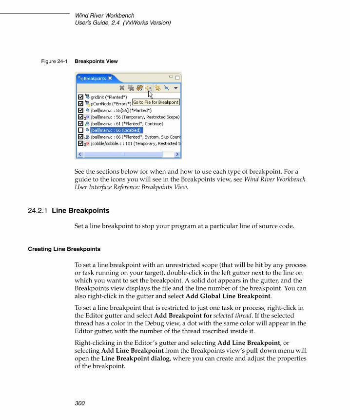
Wind River WorkbenchUser’s Guide, 2.4 (VxWorks Version)
300
See the sections below for when and how to use each type of breakpoint. For a guide to the icons you will see in the Breakpoints view, see Wind River Workbench User Interface Reference: Breakpoints View.
24.2.1 Line Breakpoints
Set a line breakpoint to stop your program at a particular line of source code.
Creating Line Breakpoints
To set a line breakpoint with an unrestricted scope (that will be hit by any process or task running on your target), double-click in the left gutter next to the line on which you want to set the breakpoint. A solid dot appears in the gutter, and the Breakpoints view displays the file and the line number of the breakpoint. You can also right-click in the gutter and select Add Global Line Breakpoint.
To set a line breakpoint that is restricted to just one task or process, right-click in the Editor gutter and select Add Breakpoint for selected thread. If the selected thread has a color in the Debug view, a dot with the same color will appear in the Editor gutter, with the number of the thread inscribed inside it.
Right-clicking in the Editor’s gutter and selecting Add Line Breakpoint, or selecting Add Line Breakpoint from the Breakpoints view’s pull-down menu will open the Line Breakpoint dialog, where you can create and adjust the properties of the breakpoint.
Figure 24-1 Breakpoints View
24 Managing Breakpoints24.2 Types of Breakpoints
301
24
For more information about the settings in this dialog, see Wind River Workbench User Interface Reference: Line Breakpoint Dialog.
24.2.2 Expression Breakpoints
Set an expression breakpoint using any C expression that will evaluate to a memory address. This could be a function name, a function name plus a constant, a global variable, a line of assembly code, or just a memory address. Expression breakpoints appear in the Editor’s gutter only when you are connected to a task.
Breakpoint conditions are evaluated after a breakpoint is triggered, in the context of the stopped task or process. Functions in the condition string are evaluated as addresses and are not executed. Other restrictions are similar to the C/C++ restrictions for calculating the address of a breakpoint using the Expression Breakpoint dialog.
Select Add Expression Breakpoint from the Breakpoints view’s pull-down menu to open the Expression Breakpoint dialog, where you can create and adjust the properties for the breakpoint.
For more information about the settings in this dialog, see the Wind River Workbench User Interface Reference: Expression Breakpoint Dialog.
24.2.3 Hardware Breakpoints
Some processors provide specialized registers, called debug registers, which can be used to specify an area of memory to be monitored. For instance, IA-32 processors have four debug address registers, which can be used to set data breakpoints or control breakpoints.
Hardware breakpoints are particularly useful if you want to stop a process when a specific variable is written or read. For example, with hardware data breakpoints, a hardware trap is generated when a write or read occurs in a monitored area of memory. Hardware breakpoints are fast, but their availability is machine-dependent. On most CPUs that do support them, only four debug registers are provided, so only a maximum of four memory locations can be watched in this way.
There are two types of hardware breakpoints:
■ A hardware data breakpoint occurs when a specific variable is read or written.

Wind River WorkbenchUser’s Guide, 2.4 (VxWorks Version)
302
■ A hardware instruction breakpoint or code breakpoint occurs when a specific instruction is read for execution.
Once a hardware breakpoint is trapped—either an instruction breakpoint or a data breakpoint—the debugger will behave in the same way as for a standard breakpoint and stop for user interaction.
Adding Hardware Instruction Breakpoints
There two ways to add a new hardware instruction breakpoint:
In the gutter (grey column) on the left of the source file, right-click and select Add Hardware Code Breakpoint. Or, double-click in the gutter to add a standard breakpoint and then, in the Breakpoints view, right-click the breakpoint you've just added and select Properties. In the last pane (Hardware) of the Properties dialog select Enable Hardware Breakpoint.
Adding Hardware Data Breakpoints
Set a hardware data breakpoint when:
■ The debugger should break when an event (such as a read or write of a specific memory address) or a situation (such as data at one address matching data at another address) occurs.
■ Threads are interfering with each other, or memory is being accessed improperly, or whenever the sequence or timing of runtime events is critical (hardware breakpoints are faster than software breakpoints).
Select Add Data Breakpoint from the Breakpoints view’s pulldown menu to open the Hardware Data Breakpoint dialog, where you can create and adjust the properties for the breakpoint.
For more information about the settings in this dialog, see the Wind River Workbench User Interface Reference: Hardware Data Breakpoints Dialog.
Converting Line or Expression Breakpoints Into Hardware Code Breakpoints
To cause the debugger to request that a line or expression breakpoint be a hardware code breakpoint, select the Hardware check box on the Hardware tab of the Line Breakpoint or Expression Breakpoint dialogs.
24 Managing Breakpoints24.3 Manipulating Breakpoints
303
24
This request does not guarantee that the hardware code breakpoint will be planted; that depends on whether the target supports hardware breakpoints, and if so, whether or not the total number supported by the target have already been planted. If the target does not support hardware code breakpoints, an error message will appear when the debugger tries to plant the breakpoint.
Comparing Software and Hardware Breakpoints
Software breakpoints work by replacing the destination instruction with a software interrupt. Therefore it is impossible to debug code in ROM using software breakpoints.
Hardware breakpoints work by comparing the break condition against the execution stream. Therefore they work in RAM, ROM or flash.
Complex breakpoints involve conditions. An example might be, “Break if the program writes value to variable if and only if function_name was called first.”
24.3 Manipulating Breakpoints
Now that you have an understanding of the different types of breakpoints, this section will show you how to work with them.
24.3.1 Importing Breakpoints
To import breakpoint properties from a file:
NOTE: Workbench will set only the number of code breakpoints, with the specific capabilities, supported by your hardware.
NOTE: If you create a breakpoint on a line that does not have any corresponding code, the debugger will plant the breakpoint on the next line that does have code. The breakpoint will appear on the new line in the Editor gutter.
In the Breakpoints view, the original line number will appear, with the new line number in square brackets [ ] after it. See the third breakpoint in Figure 24-1.
Wind River WorkbenchUser’s Guide, 2.4 (VxWorks Version)
304
1. Select File > Import > Import Breakpoints, then click Next. The Import Breakpoints dialog appears.
2. Select the breakpoint file you want to import, then click Next. The Select Breakpoints dialog appears.
3. Select one or more breakpoints to import, then click Finish. The breakpoint information will appear in the Breakpoints view, and the next time the context for that breakpoint is active in the Debug view, the breakpoint will be planted.
24.3.2 Exporting Breakpoints
To export breakpoint properties to a file:
1. Select File > Export > Export Breakpoints, then click Next. The Export Breakpoints dialog appears.
2. Select the breakpoint whose properties you want to export, and type in a file name for the exported file. Click Finish.
24.3.3 Refreshing Breakpoints
Right-clicking a breakpoint in the Breakpoints view and selecting Refresh Breakpoint causes the breakpoint to be removed and reinserted on the target. This is useful if something has changed on the target (for example, a new module was downloaded) and the breakpoint is not automatically updated.
To refresh all breakpoints in this way, select Refresh All Breakpoints from the Breakpoints view toolbar drop-down menu.
24.3.4 Disabling Breakpoints
To disable a breakpoint, clear its check box in the Breakpoints view. This retains all breakpoint properties, but ensures that it will not stop the running process. To re-enable the breakpoint, select the box again.
24.3.5 Removing Breakpoints
There are several ways to remove a breakpoint:
■ right-click it in the Editor gutter and select Remove Breakpoint
24 Managing Breakpoints24.3 Manipulating Breakpoints
305
24
■ select it in the Breakpoints view and click the Remove icon
■ right-click it in the Breakpoints view and select Remove
For more information about the Breakpoints view or any of the breakpoint dialogs, see the Wind River Workbench User Interface Reference.

Wind River WorkbenchUser’s Guide, 2.4 (VxWorks Version)
306
307
25 Debugging Projects
25.1 Introduction 307
25.2 Using the Debug View 308
25.3 Coloring Views 312
25.4 Stepping Through a Program 313
25.5 Using Debug Modes 313
25.6 Understanding Source Lookup Path Settings 317
25.7 Using the Disassembly View 318
25.8 Using the Kernel Objects View 319
25.9 Run/Debug Preferences 322
25.1 Introduction
Like other debuggers you may have used, the Wind River Workbench debugger allows you to download object modules, launch new processes, and take control of processes already running on the target.
Unlike other debuggers, it allows you to attach to multiple processes simultaneously, without affecting the state of the items you are attaching to or requiring you to disconnect from one process in order to attach to another.

Wind River WorkbenchUser’s Guide, 2.4 (VxWorks Version)
308
This chapter shows you how to use the Debug, Disassembly, and Kernel Objects views to debug your programs. For a guide to the dialogs and icons you will see while using them, see the Wind River Workbench User Interface Reference entries for those views.
25.2 Using the Debug View
Use the Debug view to monitor, control, and manipulate the processes and tasks that you are actively debugging. Unlike the Target Manager, which shows all the processes that exist on the target, the Debug view shows only the ones that are currently under debugger control.
To put a process or task under the control of the debugger and thus see it in the Debug view:
1. Connect to your target in the Target Manager view (see Connect to the Target, p.242).
2. Launch one or more processes:
■ Using a launch configuration as described in Relaunching Recently Run Programs, p.294.
■ By attaching to an already running process, as described in Attaching the Debugger to a Running Task or Process, p.296
3. Once the debugger has attached to your process, it will appear in the Debug view as shown in Figure 25-1.
NOTE: You must compile your programs using debugging symbols (the -g compiler option) to use many debugger features. The compiler settings used by the Wind River Workbench project facility’s Managed Builds include debugging symbols.
However, the Workbench debugger does not support code compiled with -02 optimization.

25 Debugging Projects25.2 Using the Debug View
309
25
Additionally, the Debug view shows processes that were launched on the target using Workbench, but which were not attached by the debugger. These launches have a special entry in the Debug view, as shown in Figure 25-2, and are only available to help you locate and terminate the process.
25.2.1 Understanding the Debug View Display
When using the Debug view, it is crucial that you understand what is represented by each level in the hierarchical tree of the process you are debugging. This is because the level of the current selection in the Debug view affects the activities that you can perform on it and controls the information displayed in other views.
Below are examples from the kernel task in Figure 25-1 for what might appear at each level of the tree, with a general description of each level.
main -ball.out - vxsim0 [Kernel task] = launch level launch name [launch type]
SIMNT: vxWorks 6.2 (Task Mode) = debug target level core name:OS name OS version (debug mode), can also be process name
tMain (Stopped - Breakpoint Hit) = thread levelthread name (state - reason for state change)
Figure 25-1 Debug View
Figure 25-2 Debug View Showing Process Not Under Debugger Control

Wind River WorkbenchUser’s Guide, 2.4 (VxWorks Version)
310
main( ) - main.c:59 = stack frame levelfunction(args) - file : line #, can also be address
In Workbench 2.4, stack arguments and argument values are not displayed in the Debug view by default. This default setting was implemented to improve debugging performance.
To activate stack-level arguments in the Debug view, select Window > Preferences > Run/Debug > Performance, then select the Retrieve stack arguments for stack frames in Debug View and Retrieve stack argument values for stack frames in Debug View checkboxes. Click OK.
How the Selection in the Debug View Affects Activities
Choosing a specific level of your debug target controls what you can do with it.
NOTE: The stack arguments reflect the current value of the stack argument variables, not the initial value of the stack arguments immediately after entering the function call.
Selected Level Action Allowed
launch Terminate or disconnect from all processes/cores for the launch debug target.
debug target Terminate or disconnect from the debug target.
Perform run control that applies to the whole process: suspend/resume all threads.
Assign color to the debug target and all its threads/tasks.
thread Terminate or disconnect; terminates individual tasks/threads, if supported by process/core.
Run control for thread: resume/suspend/step.
Assign color to thread.
stack frame Select of the stack frame causes the editor to display instruction pointer and source for stack frame.
Perform same run control as on the thread.
Assign color to thread.
Assign corresponding color for parent thread.

25 Debugging Projects25.2 Using the Debug View
311
25
Monitoring Multiple Processes
When you start processes under debugger control, or attach the debugger to running processes, they appear in the Debug view labeled with unique colors and numbers. Likewise, breakpoints that are restricted to a particular process display that process’s color/number context in the Breakpoints and Editor views.
For example, in Figure 25-3:
■ The first breakpoint in main.c (a blue circle containing a 0) is restricted to ball, the blue process numbered 0 in the Debug view.
■ The second breakpoint (a solid blue-green circle) is unrestricted.
■ The breakpoint in cobble.c (a red circle containing a 1) is restricted to cobble, the red process numbered 1 in the Debug view.
The color assigned to a process or thread can be changed by right-clicking the process or thread and selecting Color > specific color.
The context pointer (the arrow in the left gutter in main.c) indicates the statement that will execute when the process resumes.
Figure 25-3 Debug View with Breakpoint and Editor Views

Wind River WorkbenchUser’s Guide, 2.4 (VxWorks Version)
312
25.3 Coloring Views
The color context you assign to a process also carries through to other views whose scope is determined by the contents of the Debug view.
The data views that appear in the Device Debug perspective (such as the Threads or Stack Trace view) usually update to reflect whatever is currently selected in the Debug view. If you prefer, you can start colored views that are associated with a process of a particular color and update only when that process changes.
To open a view of a particular color, select Window > Show View > Other > Device Debug - color > view.
For more information about data views in the Device Debug perspective, see the Wind River Workbench User Interface Reference entries for those views.

25 Debugging Projects25.4 Stepping Through a Program
313
25
25.4 Stepping Through a Program
Once a process has stopped under debugger control (most often, at a breakpoint), you can single-step through the code, jump over subroutine calls, or resume execution. What you can do depends on what you selected in the Debug view.
When the program is stopped, you can resume operation by clicking Resume on the toolbar of the Debug view. If there are no more remaining breakpoints, interrupts, or signals, the program will run to completion (unless you click Suspend).
To step through the code one line at a time, in the Debug view, click Step Into. If you have other data views open, such as the Registers or Local Variables views, they will update with current values as you step through the code.
The effect of Step Into is somewhat different if you click Toggle Disassembly/Instruction Step Mode in the Debug view, or when the current routine has no debugging information. When this mode is set, the step buttons cause instruction-level steps to be executed instead of source-level steps. Also, the Disassembly view will appear instead of the Editor view.
To single-step without going into other subroutines, click Step Over instead of Step Into.
While stepping through a program, you may conclude that the problem you are interested in lies in the current subroutine’s caller, rather than at the stack level where your process is suspended. In this situation, if you click Step Return in Debug, execution continues until the current subroutine completes, then the debugger regains control in the calling statement.
These run control options, as well as others, are available from the Run menu as well as from the Debug view toolbar. For more information, see the Wind River Workbench User Interface Reference: Debug View.
25.5 Using Debug Modes
Depending on the type of connection you created between the debugger and the target, you may be able to operate the debugger in different modes. Different debug modes have different capabilities and limitations, which are mostly related to how the debugger interacts with the target and the processes that are being

Wind River WorkbenchUser’s Guide, 2.4 (VxWorks Version)
314
debugged. You can also create multiple debug connections to the same target, allowing you to debug in multiple modes simultaneously.
Target Connection Type Supported Modes
WDB agent on VxWorks
System Mode
■ Supports debugging the entire system using a single execution context.
■ Supports limited debugging of individual kernel tasks. The debugger can retrieve stack traces for individual tasks, but if any of the tasks is resumed and suspended, even when stepping, the entire system is resumed and suspended.
Task Mode
■ Supports debugging of kernel tasks. It allows suspending, resuming, and stepping kernel tasks individually, without affecting other kernel tasks.
■ Supports debugging of RTPs.
kgdb on Linux Kernel Mode
■ Only supports debugging the kernel using a single execution context. When the system context is suspended, the kernel, kernel threads, and user processes are suspended also.
ptrace agent on Linux
User Mode
■ Supports debugging user processes. Processes and threads within processes are suspended and resumed independently of each other.
Dual Mode on Linux
In dual mode, you must toggle between user and kernel mode depending on your debugging needs.
Kernel Mode (also called System Mode)
■ Only supports debugging the kernel using a single execution context. When the system context is suspended, the kernel, kernel threads, and user processes are suspended also.

25 Debugging Projects25.5 Using Debug Modes
315
25
As a general rule, when you are debugging the target in user mode or task mode, the debugger interacts only with the process or processes being debugged. If you suspend this process, other processes keep running. This mode is less intrusive, as it allows you to control the selected process or thread while the rest of the system can continue to operate normally.
When you are debugging in system mode, the debugger interacts with the entire system at once, so if you suspend one task, all processes and kernel tasks running on the system are suspended as well. This gives you increased control and visibility into what is happening on the system, but it is also very disruptive.
User Mode
■ Supports debugging user processes. Processes and threads within processes are suspended and resumed independently of each other.
OCD System Mode
■ Supports debugging the entire system using a single execution context.
OCD with OS Awareness for VxWorks
System Mode
■ Supports debugging entire system using a single execution context, including retrieving the full stack trace when the system is suspended.
■ Supports limited debugging of individual kernel tasks. The debugger can retrieve stack traces for individual tasks, but if any of the tasks is resumed and suspended, even when stepping, the entire system is resumed and suspended.
■ Supports viewing of individual RTPs, but does not provide run control unless the target has been configured for one-to-one MMU virtual page mapping.
OCD with OS Awareness for Linux
System Mode
■ Only supports debugging the kernel and kernel modules using a single execution context.
■ Supports viewing of processes, but the debugger cannot be attached to them.
■ Kernel objects are not available.

Wind River WorkbenchUser’s Guide, 2.4 (VxWorks Version)
316
For example, if the system maintains network connections with other systems, suspending it will cause the others to lose their network connections with the debugged system.
25.5.1 Setting and Recognizing the Debug Mode of a Connection
Right-clicking on a connection in the Target Manager or the Debug view and selecting Target Mode allows you to specify a debug mode for the connection. The currently active mode is indicated by a checkmark.
When you create a new debug connection through a launch, the connection debug mode (either system mode or task mode) is saved as a property of the launch. This mode is listed in parentheses at the end of the label of the target node in the Debug view.
Switching Debug Modes
For target connections that support switching between modes, if you switch the debug mode while a debug connection is active, this debug connection will become unavailable in the Debug view, as shown in Figure 25-4. When a debug connection is unavailable, no operations can be performed on it, except for disconnecting the debug connection.
Figure 25-4 Debug View Showing Unavailable Connections

25 Debugging Projects25.6 Understanding Source Lookup Path Settings
317
25
In the Target Manager, if you switch the target to system mode, every node in the tree will have a system mode icon painted on top. If the system mode icon does not appear, then the node and processes are in task or user mode.
25.5.2 Debugging Multiple Target Connections
You can debug processes on the same target using multiple target connections simultaneously. An example of this setup is a Linux target that has a user mode ptrace agent installed for debugging processes, and an OCD connection for halting the system and debugging the kernel.
In this situation, if the system is halted using the OCD (system mode) target connection, the user mode ptrace agent will also be halted, and the user mode target connection will be lost. When the system is resumed, the user mode target connection will be re-established.
The Target Manager and the Debug view (if a debug session is active) both provide feedback in this scenario. The Target Manager hides all the process information that was visible for the target, and displays a label back-end connection lost next to the target node. The Debug view does not end the active debug session, but it shows it as being unavailable, in the same manner as if the debug mode was switched.
25.5.3 Disconnecting and Terminating Processes
Disconnecting from a process or core detaches the debugger, but leaves the process or core in its current state.
Terminating a process actually kills the process on the target.
25.6 Understanding Source Lookup Path Settings
Source Lookup Path settings allow you to map source file paths that the debugger retrieves from an executable's symbol data (also known as the debugger path) to
NOTE: If the selected target supports terminating individual threads, you can select a thread and terminate only that thread.

Wind River WorkbenchUser’s Guide, 2.4 (VxWorks Version)
318
the correct location of the source files on the host file system and in your workspace.
The compiler generated these paths when the executable was built, but if you are debugging the executable on a different machine, then the paths to those files are no longer valid.
For information about how to set Source Lookup Path settings, see the Wind River Workbench User Interface Reference: Source Lookup Path Dialog.
25.7 Using the Disassembly View
Use the Disassembly view:
■ To examine a program when you do not have full source code for it (such as when your code calls external libraries).
■ To examine a program that was compiled without debug information.
■ When you suspect that your compiler is generating bad code (the view displays exactly what the compiler generated for each block of code).
25.7.1 Opening the Disassembly View
Unlike other Wind River Workbench views, you cannot access the Disassembly view from the Window > Show View menu—it appears automatically if the Debug view cannot display the appropriate source code file in the Editor (it appears as a tab in the Editor, labeled with the target connection being debugged).
You can open the Disassembly view manually by clicking the Debug view’s Toggle Assembly Stepping Mode toolbar icon, and by right-clicking in the Stack Trace view, then selecting Go To Code.
25.7.2 Understanding the Disassembly View Display
The Disassembly view shows source code from your file (when available), interspersed with instructions generated by the compiler. As you step through your code, the Disassembly view keeps track of the last four instructions where the

25 Debugging Projects25.8 Using the Kernel Objects View
319
25
process was suspended. The current instruction is highlighted in the strongest color, with each previous step fading in color intensity.
If the Disassembly view displays a color band at the top and bottom (here, the band is blue), then it is associated with the process with that color context in the Debug view; if no color band is displayed, then the view will update as you select different processes in the Debug view.
For more information, see Wind River Workbench User Interface Reference: Disassembly View.
25.8 Using the Kernel Objects View
Use the Kernel Objects view to monitor and manipulate data structures such as kernel tasks, message queues, semaphores, and other operating system resources.
Figure 25-5 Disassembly View

Wind River WorkbenchUser’s Guide, 2.4 (VxWorks Version)
320
During multi-process debugging, you can use the Kernel Objects view to monitor a semaphore used to control a device that two processes are using. Or you can set an RTP that uses a system resource to watch that resource during Step Over system calls.
To examine a resource in the Kernel Objects view:
1. Connect to your target in the Target Manager view (see 19.6 Connect to the Target, p.242).
2. Click the Kernel Objects tab to bring it to the foreground, then click the pull-down arrow and select your target connection.
The Kernel Objects view appears.

25 Debugging Projects25.8 Using the Kernel Objects View
321
25
25.8.1 Understanding the Kernel Objects View Display
System resources are displayed in a hierarchical tree. To see specific instances of each type of resource, click the plus sign to expand the tree.
Information about specific kernel objects is displayed in the Properties view.
Figure 25-6 Kernel Objects View

Wind River WorkbenchUser’s Guide, 2.4 (VxWorks Version)
322
For a guide to the icons in the Kernel Objects view, see Wind River Workbench User Interface Reference: Kernel Objects View.
25.9 Run/Debug Preferences
For information about how to set debug and run control preferences, see Wind River Workbench User Interface Reference: Debug View.

323
26 Troubleshooting
26.1 Introduction 323
26.2 Startup Problems 324
26.3 General Problems 327
26.4 Error Messages 329
26.5 Troubleshooting VxWorks Configuration Problems 341
26.6 Error Log View 344
26.7 Error Logs Generated by Workbench 344
26.8 Technical Support 351
26.1 Introduction
This chapter displays some of the errors or problems that may occur at different points in the development process, and what steps you can take to correct them. It also provides information about the log files that Workbench can collect, and how you can create a ZIP file of those logs to send to Wind River support.
Wind River WorkbenchUser’s Guide, 2.4 (VxWorks Version)
324
26.2 Startup Problems
This section discusses some of the problems that might cause Workbench to have trouble starting.
Workspace Metadata is Corrupted
If Workbench crashes, some of your settings could get corrupted, preventing Workbench from restarting properly.
1. To test if your workspace is the source of the problem, start Workbench, specifying a different workspace name.
On Windows
Select Start > Programs > Wind River > Wind River Workbench 2.4 > Wind River Workbench 2.4, then when Workbench asks you to choose a workspace, enter a new name (workspace2 or whatever you prefer).
Or, if the Workbench startup process does not get all the way to the Workspace Launcher dialog, or does not start at all, start it from a terminal window:
> installDir\workbench-2.3\wrwb\2.3\x86-win32\bin\wrwb.exe -data newWorkspace
On Linux or Solaris
Start Workbench from a terminal window, specifying a new workspace name:
> ./startWorkbench.sh -data newWorkspace
2. If Workbench starts successfully with a new workspace, exit Workbench, then delete the .metadata directory in your original Workbench installation (installDir/workspace/.metadata).
3. Restart Workbench using your original workspace. The .metadata directory will be recreated and should work correctly.
4. Because the .metadata directory contains project information, that information will be lost when you delete the directory.
To recreate your project settings, reimport your projects into Workbench (File > Import > Existing Project into Workspace). For more information about importing projects, see Importing Projects, p.132.
26 Troubleshooting26.2 Startup Problems
325
26
.workbench-2.4 Directory is Corrupted
1. To test if your %USERPROFILE%/.workbench-2.4 directory is the source of the problem, rename it to a different name, then restart Workbench.
2. If Workbench starts successfully, exit Workbench, then delete the old version of your %USERPROFILE%/.workbench-2.4 directory (the one you renamed).
3. Restart Workbench. The %USERPROFILE%/.workbench-2.4 will be recreated and should work correctly.
4. Because the .workbench-2.4 directory contains Eclipse configuration information, any information about manually configured Eclipse extensions or plug-ins will be lost when you delete the directory.
To make them available again within Workbench, you must re-register them (Help > Software Updates > Manage Configuration). For more information about registering plug-ins, see Adding Plug-in Functionality to Workbench, p.359.
Registry Unreachable (Windows)
When Workbench starts and it does not detect a default Wind River registry, it launches one. After you quit Workbench, the registry is kept running since it is needed by all Wind River tools. You do not need to ever kill the registry.
If you do stop it, however, it stores its internal database in the file installDir/.wind/wtxregd.hostname.
If this file later becomes unwritable, the registry cannot start, and Workbench will display an error.
NOTE: Make sure you rename the %USERPROFILE%/.workbench-2.4 directory (for example, on Windows XP it could be C:\Documents and Settings\username\.workbench-2.4).
Do not rename the installDir/workbench-2.4 directory.

Wind River WorkbenchUser’s Guide, 2.4 (VxWorks Version)
326
This error may also occur if you install Workbench to a directory to which you do not have write access, such as installing Workbench as an administrator and then trying to run it as yourself.
Workspace Cannot be Locked (Linux and Solaris)
If you start Workbench and select a workspace, you may see a Workspace Cannot be Locked error.
There are three possible causes for this error:
1. Another user has opened the same workspace. A workspace can only be used by one user at a time.
2. You installed Workbench on a file system that does not support locking.
Use the following command at a terminal prompt to start Workbench so that it creates your workspace on a file system which does allow locking, such as a directory on a local disk:
./startWorkbench.sh -configuration directory that allows locking
For example:

26 Troubleshooting26.3 General Problems
327
26
./startWorkbench.sh -configuration /usr/local/yourName
3. On some window managers (e.g. gnome) you can close the window without closing the program itself and deleting all running processes. This results in running processes maintaining a lock on special files in the workspace that mark a workspace as open.
To solve the problem, kill all Workbench and Java processes that have open file handles in your workspace directory.
26.2.1 Pango Error on Linux
If the file pango.modules is not world readable for some reason, Workbench will not start and you may see an error in a terminal window similar to
** (<unknown>:21465): WARNING **: No builtin or dynamically loaded modules were found. Pango will not work correctly. This probably means there was an error in the creation of:
'/etc/pango/pango.modules'You may be able to recreate this file by running pango-querymodules.
Changing the file’s permissions to 644 will cause Workbench to launch properly.
26.3 General Problems
This section describes problems that are not associated with any particular Workbench component.
26.3.1 Java Development Tools (JDT) Dependency
Some third party plug-ins are dependent on JDT. If a plug-in you are interested in requires JDT, you should download it from the official Eclipse Website:
http://download.eclipse.org/eclipse/downloads/drops/R-3.0.1-200409161125/eclipse-JDT-3.0.1.zip
A list of official mirror sites is here:
http://www.eclipse.org/downloads

Wind River WorkbenchUser’s Guide, 2.4 (VxWorks Version)
328
26.3.2 Help System Does Not Display on Solaris or Linux
Eclipse comes preconfigured to use Mozilla on Solaris and Linux, and it expects it to be in your path. If Mozilla is not installed, or is not in your path, you must set the correct path to the browser or Workbench will not display help or other documentation.
To manually set the browser path in Workbench:
1. Select Window > Preferences > Help.
2. Click Custom Browser (user defined program), then in the Custom Browser command field type or browse to your browser launch program. Click OK.
■ On Solaris, a sample Netscape browser launch command is "/usr/dt/bin/netscape" %1, though you should enter the command line that is appropriate for your browser.
■ On Linux, sample Mozilla browser launch commands are “/usr/bin/mozilla” %1 and kfmclient openURL %1, though you should enter the command line that is appropriate for your browser.
26.3.3 Help System Does Not Display on Windows
The help system can sometimes fail to display help or other documentation due to a problem in McAfee VirusScan 8.0.0i (and possibly other virus scanners as well).
For McAfee VirusScan 8.0.0i, the problem is known to be resolved with patch10 which can be obtained from Network Associates. As a workaround, the problem can be avoided by making sure that McAfee on-access-scan is turned on and allowed to scan the TEMP directory as well as *.jar files.
More details regarding this issue have been collected by Eclipse Bugzilla #87371 at https://bugs.eclipse.org/bugs/show_bug.cgi?id=87371.
26.3.4 Removing Unwanted Target Connections
If you have trouble deleting a target connection session for any reason, use wtxtcl.
1. Start wtxtcl from a terminal window.
% wtxtcl
26 Troubleshooting26.4 Error Messages
329
26
2. List all entries in the registry.
wtxtcl> wtxInfo
3. Unregister the offending entry or entries (the full entry name must be used).
wtxtcl> wtxUnregister tgt_localhost@manebogad
26.4 Error Messages
Some errors display an error dialog directly on the screen, while others that occurred during background processing only display this icon in the lower right corner of Workbench window.
Hovering your mouse over the icon displays a pop-up with a synopsis of the error. Later, if you closed the error dialog but want to see the entire error message again, double-click the icon to display the error dialog or look in the Eclipse Log, p.345.
This section explains error messages that appear in each Workbench component.
26.4.1 Project System Errors
For general information about the Project System, see 4. Projects Overview.
Project Already Exists
If you deleted a project from the Project Navigator but chose not to delete the project contents from your workspace, then you try to create a new project with the same name as the old project, you will see this error:

Wind River WorkbenchUser’s Guide, 2.4 (VxWorks Version)
330
If you click Yes, your old project contents will be overwritten with the new project. If you want to recreate the old project in Wind River Workbench, click No, then right-click in the Project Navigator, select Import, then select Existing Project into Workspace.
Type the name of your old project or browse to the old project directory in your workspace, click OK, then click Finish. Your old project will appear in the Project Navigator.
Cannot Create Project Files in Read-only Location
When Workbench creates a project, it creates a .wrproject file and other metadata files it needs to track settings, preferences, and other project-specific information. So if your source files are in a read-only location, Workbench cannot create your project there.
To work around this problem, you must create a new project in your workspace, then create a folder that links to the location of your source files.
1. Create a User-defined Project in your workspace by selecting File > New > User-Defined Project. The Target Operating System dialog appears.
2. Select a target operating system from the drop-down list, then click Next. The Project dialog appears.
3. Type in a name for your project, select Create project in workspace, then click Next.
4. Click Next to accept the default settings in the next dialogs, then click Finish to create your project.

26 Troubleshooting26.4 Error Messages
331
26
5. In the Project Navigator, right-click your new project and select New > Folder. The Folder dialog appears.
6. Type in a name for your folder, then click Advanced and select the Link to folder in the file system checkbox.
7. Type the path or click Browse and navigate to your source root directory, then click OK to create the new folder.
8. Click the plus next to the folder to open it, and you will see the source files from your read-only source directory. Eclipse calls items incorporated into projects in this way linked resources.
26.4.2 Build System Errors
For general information about the Build System, see 16. Build Properties and the Build Console.
Building Projects While Connected to a Target
If you try to build a project while you have a target connection active in the Target Manager, you may see an error. This happens when any of the files that need to be built contain symbol information, and therefore have been locked by the debugger.
You can continue your build by clicking OK, but be advised that you will need to disconnect your target and restart the build if you see an Build Console error message similar to dld: Can’t create file XXX: Permission denied.
To avoid this problem, Workbench loads files up to a certain size completely into memory so no file lock is needed. To specify the largest symbol file that can be loaded into memory, select Window > Preferences > Target Manager > Debug Server Settings > Symbol File Handling Settings and specify a file size up to 60M.
Workflow for Cases Where You Need to Continually Rebuild Objects in Use by Your Target
1. Create a launch configuration for your debugging task. When you need to disconnect your target in order to free your images for the build process, the launch configuration allows you to automatically connect, build, download, and run your process with a single click.
NOTE: This mechanism cannot be used for managed-build projects, only for user-defined projects.

Wind River WorkbenchUser’s Guide, 2.4 (VxWorks Version)
332
You can even specify that your project should be rebuilt before it is launched by selecting Window > Preferences > Run/Debug > Launching, and then selecting Build (if necessary) before launching. For more information about launch configurations, see 23. Launching Programs.
■ When you work with processes or RTPs, make sure that your process is terminated before you rebuild or relaunch. You can then safely ignore the warning (and check the Do not show this dialog again box).
■ When you work with Downloadable Kernel Modules or user-built kernel images, just let the build proceed. If the Link error message appears, either disconnect your target or unload all modules, then rebuild or relaunch.
Workflow for Using On-Chip Debugging to Debug Standalone Modules Loaded on Your Target
1. Create a Reset & Download-type launch configuration for your application, and enable the Build before launch option (by selecting Window > Preferences > Run/Debug > Launching > Build (if required) before launching).
2. Run the launch configuration to debug your code. Make any changes to the source files and save them. Note that saving before unloading the symbols allows the debugger to track your breakpoints.
3. Before relaunching or rebuilding, unload the modules from the target by selecting them in the Target Manager and pressing the Delete key (you can multi-select if there are multiple modules).
4. Press the Debug button to relaunch your application. It will automatically rebuild, redownload, reset, and attach the debugger.
Problems Building Workbench 2.x Projects Imported Into Workbench 2.4
If you have trouble building projects that you imported from a previous version of Workbench, check if the .wrproject file contains an entry for platform. If not, the project is not compatible and has to be patched to work with the newest version of Workbench.
To patch the .wrproject file:
1. Open the file with the Workbench text editor by right-clicking the file in the Project Navigator, then selecting Open With > Text Editor.

26 Troubleshooting26.4 Error Messages
333
26
If the .wrproject file is not visible in the Project Navigator, click the downward arrow on the right side of the Project Navigator toolbar and select Filters to open the Project Navigator Filters dialog.
Select the checkbox next to .wr*, then click OK. The .wrproject file should now appear in the Project Navigator.
2. Locate the line at the beginning of the file similar to:
<properties root="1" type="RealTimeProcessProject"/>
3. Add platform="projectplatform" to the end of the line, with projectplatform replaced by one of VxWorks, Linux, or Standalone, depending on the platform to which the project type belongs.
4. The result should appear similar to the following:

Wind River WorkbenchUser’s Guide, 2.4 (VxWorks Version)
334
5. Save and close the .wrproject file. Your project should now build properly.
Build All Command Builds Projects Whose Resources have not Changed
Workbench may enter a state where selecting Project > Build All builds projects whose resources have not changed since the last build.
This happens only if Auto-Build (Project > Build Automatically) was previously enabled. If you switch this feature off, you must do a manual clean for all projects (Project > Clean) in order to re-enable building for previously built projects.
26.4.3 Target Manager Errors
For general information about the Target Manager, see 19. Connecting to Targets.
Troubleshooting Connecting to a Target
If you see the following error:
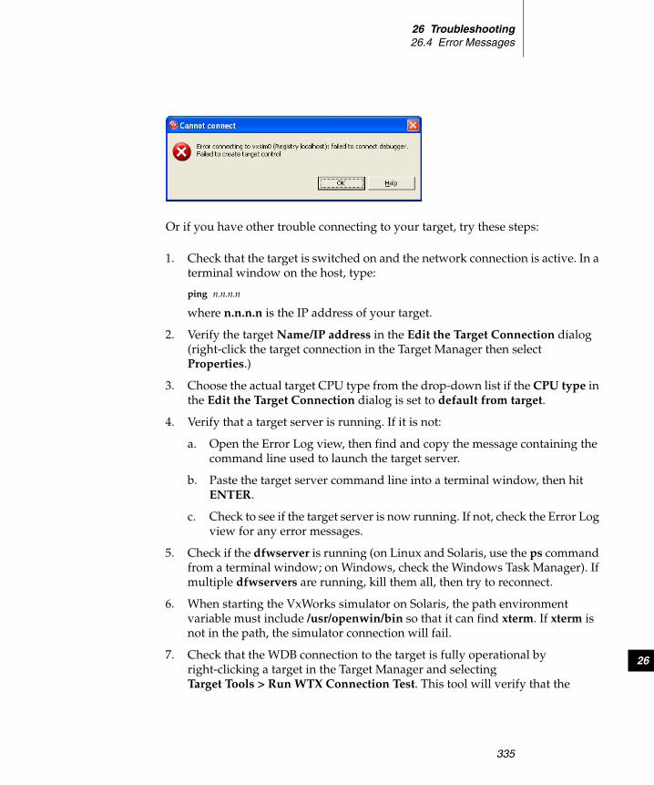
26 Troubleshooting26.4 Error Messages
335
26
Or if you have other trouble connecting to your target, try these steps:
1. Check that the target is switched on and the network connection is active. In a terminal window on the host, type:
ping n.n.n.n
where n.n.n.n is the IP address of your target.
2. Verify the target Name/IP address in the Edit the Target Connection dialog (right-click the target connection in the Target Manager then select Properties.)
3. Choose the actual target CPU type from the drop-down list if the CPU type in the Edit the Target Connection dialog is set to default from target.
4. Verify that a target server is running. If it is not:
a. Open the Error Log view, then find and copy the message containing the command line used to launch the target server.
b. Paste the target server command line into a terminal window, then hit ENTER.
c. Check to see if the target server is now running. If not, check the Error Log view for any error messages.
5. Check if the dfwserver is running (on Linux and Solaris, use the ps command from a terminal window; on Windows, check the Windows Task Manager). If multiple dfwservers are running, kill them all, then try to reconnect.
6. When starting the VxWorks simulator on Solaris, the path environment variable must include /usr/openwin/bin so that it can find xterm. If xterm is not in the path, the simulator connection will fail.
7. Check that the WDB connection to the target is fully operational by right-clicking a target in the Target Manager and selecting Target Tools > Run WTX Connection Test. This tool will verify that the

Wind River WorkbenchUser’s Guide, 2.4 (VxWorks Version)
336
communication link is correct. If there are errors, you can use the WTX and WDB logs to better track down what is wrong with the target.
Exception on Attach Errors
If you try to run a task or launch an RTP and the Target Manager is unable to comply, it will display an Exception on Attach error containing useful information.
Build errors can lead to a problem launching your task or process; if one of the following suggestions does not solve the problem, try launching one of the pre-built example projects delivered with Workbench.
If the host shell was running when you tried to launch your task or process, try closing the host shell and launching again.
Error Launching a VxWorks Real-time Process on Linux
If you get an error when launching a VxWorks RTP from a Red Hat Workstation, update 3 host system, try these steps:
1. Delete boothost: from the beginning of the Exec Path on Target field of the Run Real-time Process dialog.
2. Add a new object path mapping to the target server connection properties that does not have boothost: in the host path.
Error When Running a Task Without Downloading First
You will see the following error if you try to run a kernel task without first downloading it to your target:

26 Troubleshooting26.4 Error Messages
337
26
Processes can be run directly from the Project Navigator, but kernel tasks must be downloaded before running. Right-click the output file, select Download, fill in the Download dialog, then click OK.
If you see this error and you did download the file, open a host shell for your connection, and try to run the task from the host shell. Type:
lkup entrypoint
to see if your entry point is there.
Downloading an Output File Built with the Wrong Build Spec
If you built a project with a build spec for one target, then try to download the output file to a different target (for example, you build the project for the simulator, but now you want to run it on a hardware target), you will see this error:
To select the correct build spec, right-click the output file in the Project Navigator, select Set Active Build Spec, select the appropriate build spec from the dialog, then rebuild your project.
Your project should now download properly.
Error if Exec Path on Target is Incorrect
If the Exec Path on Target field of the Run Real-time Processes dialog does not contain the correct target-side path to the executable file (if, for example, it contains the equivalent host-side path instead) you will see this error:

Wind River WorkbenchUser’s Guide, 2.4 (VxWorks Version)
338
1. If the target-side path looks correct but you still get this error, check the following:
a. Recheck the path you gave. Even if you used the Browse button to locate the file, it will be located in the host file system. The Object Path Mapping that is defined for your target connection will translate it to a path in the target file system, which is then visible in the Exec Path edit field. If your Object Path Mapping is wrong, the Exec Path will be wrong, so it is important to check.
Troubleshooting Running a Process
If you have trouble running your process from the Run Process or Run Real-time Process dialog, try these steps:
1. If the error Cannot create context appears, verify that the Exec Path on Target is a path that is actually visible on the target (and doesn’t contain the equivalent host-side path instead).
a. Right-click the process executable in the Project Navigator or right-click Processes or Real-time Processes in the Target Manager and select Run Real-time Process.
b. Copy the exec path and paste it into the Output View > TargetConsole Tab (at the bottom of the view). Verify that the program runs directly on the target.
2. If the program runs but symbols are not found, manually load the symbols by right-clicking the process and selecting Load Symbols.

26 Troubleshooting26.4 Error Messages
339
26
3. Check your Object Path Mappings to be sure that target paths are mapped to the correct host paths. See 20.2.3 Object Path Mappings Page, p.250 for details on setting up your Object Path Mappings.
a. Open a host shell and type:ls execpath
If you have a target shell, type the same command.
b. In the host shell, type:devs
to see if the prefix of the Exec Path (for example, host:) is correct.
4. If the Exec Path is correct, try increasing the back-end timeout value of your target server connection (see Advanced Target Server Options, p.248 for details).
5. From a target shell or Linux console, try to launch the RTP or process.
6. Verify that the vxWorks node in the Target Manager view has a small S added to the icon, indicating that symbols have been loaded for the Kernel.
a. If not, verify that the last line of your Object Path Mappings table displays a target path of <any> corresponding to a host path of <leave path unchanged>.
26.4.4 Launch Configuration Errors
If a launch configuration is not working properly, delete it by clicking Delete below the Debug dialog Configurations list.
If you cannot delete the launch configuration using the Delete button, navigate to installDir/workspace/.metadata/.plugins/org.eclipse.debug.core/.launches and delete the .launch file with the exact name of the problematic launch configuration
.
Troubleshooting Launch Configurations
If you click the Debug icon (or click the Debug button from the Launch Configuration dialog) and get a “Cannot create context” error, check the Exec Path on the Main tab of the Debug dialog to be sure it is correct. Also check your Object Path Mappings (see 20.2.3 Object Path Mappings Page, p.250 for information about Object Path Mappings).
! WARNING: Do not delete any of the com.windriver.ide.*.launch files.

Wind River WorkbenchUser’s Guide, 2.4 (VxWorks Version)
340
If you still get the error, check to be sure that the process you are trying to run is a Real-time Process, and not a Downloadable Kernel Module or some other type of executable.
For general information about launch configurations, see 23. Launching Programs.
26.4.5 Debugger Errors
Shared Library Problems
If you are having trouble working with shared libraries, try these steps:
1. If you are trying to run an executable and shared libraries located on your host machine's disk, make sure you can see the host machine's disk and the location of the shared libraries from the target.
Use a target shell, or the @ls command from a host shell, to check this.
2. Set SHAREDLIB_VERSION to 1 in order to generate the proper versioned shared object.
3. Make sure that a copy of libc.so.1 is located in a place where the RTP has access to it. By default it should be located with the executable files, but you may locate it elsewhere as long as you use the compiler's -rpath option or the environment variable LD_LIBRARY_PATH.
26.4.6 Static Analysis Errors
If at any point Workbench is unable to open the cross reference database, you will see this error:
There are many reasons the cross reference database may be inaccessible, including:

26 Troubleshooting26.5 Troubleshooting VxWorks Configuration Problems
341
26
■ The database was not closed properly at the end of the last Workbench session running within the same workspace. This happens if the process running Workbench crashed or was killed.
■ Various problems with the file system, including wrong permissions, a network drive that is unavailable, or a disk that is full.
You have several choices for how to respond to this error dialog:
■ Retry—the same operation is performed again, possibly with the same failure again.
■ Recover—the database is opened and a repair operation is attempted. This may take some time but you may recover your cross reference data.
■ Clear Database—the database is deleted and a new one is created. All your cross reference data is lost and your workspace will be reparsed the next time you open the call tree.
■ Close—the database is closed. No cross reference data is available, nor will it be generated. At the beginning of the next Workbench session, an attempt to open the database will be made again.
26.5 Troubleshooting VxWorks Configuration Problems
If you encountered problems booting or exercising VxWorks, there are many possible causes. This section discusses the most common sources of error. Please read 26.5.1 What to Check, p.341 before contacting Wind River customer support. Often, you can locate the problem just by re-checking the installation steps, your hardware configuration, and so forth.
26.5.1 What to Check
Most often, a problem with running VxWorks can be traced to configuration errors in hardware or software. Consult the following checklist to locate a problem.
Wind River WorkbenchUser’s Guide, 2.4 (VxWorks Version)
342
Hardware Configuration
■ If you are using an emulator . . .
See the Wind River ICE for Wind River Workbench Hardware Reference or the Wind River Probe for Wind River Workbench Hardware Reference for information on troubleshooting those connections.
■ Limit the number of variables
Start with a minimal configuration of a single target.
■ Check that the RS-232 cables are correctly constructed
In most cases, the documentation accompanying your target system describes its cabling requirements. A common problem—make sure your serial cable is a NULL modem cable, if that is what your target requires.
■ Check the boot ROM(s) for correct insertion
If the target seems completely dead when applying power (some have front panel LEDs) or shows some error condition (for example, red lights), the boot ROMs may be inserted incorrectly.
■ Press the RESET button if required
Some system controller boards do not reset completely on power-on; you must reset them manually. Consult the target documentation if necessary.
■ Make sure all boards are jumpered properly
Refer to the target information reference for your BSP and the target documentation to determine the correct dip switch and jumper settings for your target and Ethernet boards.
NOTE: If you need to use a gender converter to connect your serial cable, it is most likely not the right kind of cable. NULL modem cables tend to have same gender connectors on each end, such as both female or both male. Straight through cables tend to have one male and one female connector. Changing the gender of a cable rarely has the desired results.

26 Troubleshooting26.5 Troubleshooting VxWorks Configuration Problems
343
26
Booting Problems
■ Check the Ethernet transceiver site
For example, connect a known working system to the Ethernet cable and check whether the network functions.
■ Verify IP addresses
An IP address consists of a network number and a host number. There are several different classes of Internet addresses that assign different parts of the 32-bit Internet address to these two parts, but in all cases, the network number is given in the most significant bits and the host number is given in the least significant bits. The simple configuration described in 3.4 Booting VxWorks, p.43 assumes that the host and target are on the same network—they have the same network number. If the target Internet address is not on the same network as the host, the VxWorks boot program displays the following message:
Error loading file: errno = 0x33.
See the errnoLib reference entry for a discussion of VxWorks error status values.
■ Verify FTP server permissions
Check the FTP server configuration. See Configuring FTP on Windows, p.34 for more information on configuring the FTP server if you are using WFTPD (shipped by Wind River). Otherwise, consult your system documentation on the FTP Server shipped with it.
■ Helpful troubleshooting tools
When tracking down configuration problems, ping, arp -a, and netstat -r are useful tools. For more information, see B. Glossary.
Target Server Problems
■ Check back end serial port
If you use a WDB Serial connection to the target, make sure you have connected the serial cable to a port on the target system that matches your target-agent configuration. The agent uses serial channel 1 by default, which is different from the channel used by VxWorks as a default console (channel 0). Your target’s ports may be numbered starting at one; in that situation, VxWorks channel one corresponds to the port labeled “serial 2.”

Wind River WorkbenchUser’s Guide, 2.4 (VxWorks Version)
344
■ Verify path to VxWorks image
The target server requires a host-resident image of the VxWorks run-time system. By default, it obtains a path for this image from the target agent (as recorded in the target boot parameters). In some cases (for example, if the target boots from a local device), this default is not useful.
In that situation, create a new Target Server Connection definition in the Target Manager, and use the -c filename option in the Advanced Target ServerOptions field to specify the path to a host-resident copy of the VxWorks image.
Check the WFTPD Server Log
The WFTPD server log displays very helpful plain text messages. For information about how to enable logging FTP activities, see Configuring FTP on Windows, p.34.
26.6 Error Log View
Some errors direct you to the Error Log view, which displays internal errors thrown by the platform or your code. For more information about the Error Log, see Wind River Workbench User Interface Reference: Error Log View.
26.7 Error Logs Generated by Workbench
Workbench has the ability to generate a variety of useful log files. Some Workbench logs are always enabled, some can be enabled using options within Workbench, and some must be enabled by adding options to the executable command when you start Workbench.
This section describes the logs, tells you how to enable them (if necessary), and how to collect them into a ZIP file you can send to Wind River support representatives.

26 Troubleshooting26.7 Error Logs Generated by Workbench
345
26
26.7.1 Creating a ZIP file of Logs
Once all the logs you are interested in have been enabled, Workbench automatically collects the information as you work.
To create a ZIP file to send to a Wind River support representative:
1. Select Help > Collect Log Files. The dialog opens.
2. Type the full path and filename of the ZIP file you want to create (or browse to a location and enter a filename) then click Finish. The ZIP file is created in the specified location, and contains all information collected to that point.
3. To discontinue logging (for those logs that are not always enabled) uncheck the boxes on the Target Server Options tab, or restart Workbench without the additional options.
26.7.2 Eclipse Log
The information displayed in the Error Log view is a subset of this log’s contents.
How to Enable Log
This log is always enabled.

Wind River WorkbenchUser’s Guide, 2.4 (VxWorks Version)
346
What is Logged
■ All uncaught exceptions thrown by Eclipse java code.
■ Most errors and warnings that display an error dialog in Workbench.
■ Additional warnings and informational messages.
What it Can Help Troubleshoot
■ Unexpected error popups.
■ Bugs in Workbench java code.
■ Bugs involving intercomponent communication.
26.7.3 DFW GDB/MI and Debug Tracing Logs
The DFW logs are a record of all communication and state changes between the debugger back end (the “debugger framework”, or DFW) and other views within Workbench, including the Target Manager, debugger views, and OCD views.
How to Enable Log
These logs are always enabled.
To change the maximum debug server log file size, select Window > Preferences > Target Manager > Debug Server Settings. In the Maximum Debug Server Log File Size field, change the default size to the size you prefer (or to the size requested by a Wind River support representative).
Changing this field to 0 disables the collecting of dfwserver.log information.
What is Logged
Internal exceptions in the debugger back end, as well as all commands sent between Workbench and the debugger back end.
What it Can Help Troubleshoot
Debugger, Target Manager, and debugger back end-related bugs.

26 Troubleshooting26.7 Error Logs Generated by Workbench
347
26
26.7.4 Debugger Views GDB/MI Log
This log shows the same information as reported in the DFW GDB/MI and Debug Tracing Logs, p.346.
How to Enable Log
You must enable this log before you start Workbench. Do this by adding these parameters to the Workbench executable command:
-vmargs -DDFE.Debug=true
What is Logged
Same as DFW GDB/MI and Debug Tracing Logs, p.346, except with Workbench time-stamps.
What it Can Help Troubleshoot
Debugger and Target Manager-related bugs.
26.7.5 Debugger Views Internal Errors Log
How to Enable Log
You must enable this log before you start Workbench. Do this by adding these parameters to the Workbench executable command:
-vmargs -DDFE.Debug=true
What is Logged
Exceptions caught by the Debugger views messaging framework.
What it Can Help Troubleshoot
Debugger views bugs.
26.7.6 Debugger Views Broadcast Message Debug Tracing Log
How to Enable Log
You must enable this log before you start Workbench. Do this by adding these parameters to the Workbench executable command:

Wind River WorkbenchUser’s Guide, 2.4 (VxWorks Version)
348
-vmargs -DDFE.Debug=true
What is Logged
Debugger views internal broadcast messages.
What it Can Help Troubleshoot
Debugger views bugs.
26.7.7 Target Server Output Log
This log contains the messages printed by the target server while running. These messages typically indicate errors during various requests sent to it, such as load operations. Upon startup, if a fatal error occurs (such as a corefile checksum mismatch) then this error will be printed before the target server exits.
How to Enable Log
■ Enable this log from the Target Manager by right-clicking the target connection, selecting Properties, selecting the Target Server Options tab, then clicking Edit.
Select the Logging tab, then check the box next to Enable output logging and provide a filename and maximum file size for the log. Click OK.
■ Enable this log from the command line using the -l path/filename and -lm maximumFileSize options to the target server executable. For more information about target server commands, see Wind River Documentation > References > Host API and Command References> Wind River Host Tools API Reference > tgtsvr.
What is Logged
■ Fatal errors on startup, such as library mismatches and errors during exchange with the registry.
■ Standard errors, such as load failure and RPC timeout.
What it Can Help Troubleshoot
■ Debugger back end
■ Target Server
■ Target Agent

26 Troubleshooting26.7 Error Logs Generated by Workbench
349
26
26.7.8 Target Server Back End Log
This log records all requests sent to the WDB agent.
How to Enable Log
■ Enable this log from the Target Manager by right-clicking the target connection, selecting Properties, selecting the Target Server Options tab, then clicking Edit.
Select the Logging tab, then check the box next to Enable backend logging and provide a filename and maximum file size for the log. Click OK.
■ Enable this log from the command line using the -Bd path/filename and -Bm maximumFileSize options to the target server executable. For more information about target server commands, see Wind River Documentation > References > Host API and Command References> Wind River Host Tools API Reference > tgtsvr.
What is Logged
Each WDB request sent to the agent. For more information about WDB services, see Wind River Documentation > References > Host API and Command References > Wind River WDB Protocol API Reference.
What it Can Help Troubleshoot
■ Debugger back end
■ Target Server
■ Target Agent
26.7.9 Target Server WTX Log
This log records all requests sent to the target server.
How to Enable Log
■ Enable this log from the Target Manager by right-clicking the target connection, selecting Properties, selecting the Target Server Options tab, then clicking Edit.
Wind River WorkbenchUser’s Guide, 2.4 (VxWorks Version)
350
Select the Logging tab, then check the box next to Enable WTX logging and provide a filename and maximum file size for the log. Click OK.
■ Enable this log from the command line using the -Wd path/filename and -Wm maximumFileSize options to the target server executable. For more information about target server commands, see Wind River Documentation > References > Host API and Command References> Wind River Host Tools API Reference > tgtsvr.
What is Logged
Each WTX request sent to the target server. For more information about WTX services, see Wind River Documentation > References > Host API and Command References > WTX C Library Reference > wtxMsg.
What it Can Help Troubleshoot
■ Debugger back end
■ Target Server
■ Target Agent
26.7.10 Target Manager Debug Tracing Log
This log prints useful information about creation and modification of Target Manager internal structures, as well as inconsistencies or warning conditions in the subsystems the Target Manager interoperates with.
How to Enable Log
You must enable this log before you start Workbench. Do this by adding these parameters to the Workbench executable command:
-debug -vmargs -Dcom.windriver.ide.target.DEBUG=1.
What is Logged
Target Manager internal debug errors.
What it Can Help Troubleshoot
Inconsistencies in the debugger back end.

26 Troubleshooting26.8 Technical Support
351
26
26.7.11 Static Analysis Parser Logs
These logs contain information that can help a Wind River technical support representative to resolve problems with the source code parsers.
How to Enable Logs
Enable these logs by right-clicking a resource or resources in the Project Navigator or the Editor and selecting Static Analysis > Generate Parser Logs. From the list of logs that appears, select the logs that were requested by a technical support representative (the jobs log and the performance log are selected by default). Click OK.
What is Logged
■ The jobs log describes what the parsers were instructed to do.
■ The performance log lists the source files the parsers spent the most time with.
■ The PI4 interface and symbols logs contains the result of parsing.
■ The debug log shows how the cpp-parser uses internal caching strategies.
■ The tokens log lists every token processed by the cpp-parser.
What it Can Help Troubleshoot
Problems related to excessive parsing time. The performance log can help pinpoint if there are single files that require more parsing time, or if there are simply many resources to parse.
In a case where results of the analysis are different from what you expect but Wind River support cannot reproduce the problem, the PI4 and symbol logs are crucial in helping support representatives see the raw data the parsers are generating.
The debug and tokens logs are needed very seldom, but are useful to Wind River developers working on the parsers themselves.
26.8 Technical Support
If you have questions or problems with Workbench or with VxWorks after completing the above troubleshooting section, or if you think you have found an

Wind River WorkbenchUser’s Guide, 2.4 (VxWorks Version)
352
error in the software, please see the Wind River Workbench Release Notes for your platform for any additional information. Contact information for the Wind River Technical Support organization is also listed in the release notes. Your comments and suggestions are welcome.

353
PAR T VI
Updating
27 Integrating Plug-ins ............................................ 355

Wind River WorkbenchUser’s Guide, 2.4 (VxWorks Version)
354

355
27 Integrating Plug-ins
27.1 Introduction 355
27.2 Finding New Plug-ins 356
27.3 Incorporating New Plug-ins into Workbench 356
27.4 Using Workbench with ClearCase Views 360
27.5 Downloading and Installing Java Development Tools (JDT) 361
27.6 Managing Multiple Plug-in Configurations 362
27.7 Using Workbench in an Eclipse Environment 363
27.1 Introduction
Because Wind River Workbench is based on Eclipse, you can incorporate new modules into Workbench without having to recompile or reinstall it. These new modules are called plug-ins, and they can deliver new functionality and tools to your copy of Wind River Workbench.
Many developers enjoy creating new plug-ins and sharing their creations with other Eclipse users, so you will find many Web sites with interesting tools and programs available for you to download and incorporate into your Workbench installation.

Wind River WorkbenchUser’s Guide, 2.4 (VxWorks Version)
356
Some plug-ins are dependent on Java Development Tools (JDT). This chapter will show you how to download and install it.
27.2 Finding New Plug-ins
In addition to the Eclipse Web site, http://www.eclipse.org, many other Web sites offer a wide variety of Eclipse plug-ins. Here are a few:
http://www.eclipse-plugins.info/eclipse/plugins.jsp
http://www.eclipseplugincentral.com/
http://eclipse-plugins.2y.net/eclipse/
http://www.sourceforge.net/
27.3 Incorporating New Plug-ins into Workbench
Many developers who download plug-ins prefer to create a new directory for each one, rather than unzipping the files directly into their Workbench installation directory. There are many advantages to this approach:
■ The default Workbench installation does not change.
■ You do not lose any of your plug-ins if you update or reinstall Workbench.
■ Plug-ins do not overwrite each other’s files.
■ You know which files to replace when an update to the plug-in is available.
27.3.1 Creating a Plug-in Directory Structure
To make your plug-ins easier to manage, create a directory structure for them outside your Workbench installation directory.
1. Create a directory to hold your plug-ins. It can have any descriptive name you want, for example, eclipseplugins.

27 Integrating Plug-ins27.3 Incorporating New Plug-ins into Workbench
357
27
2. Inside this directory, create a directory for each plug-in you want to install. These directories can also have any descriptive name you want.
3. Inside each plug-in directory, create a directory named eclipse. This directory must be named eclipse, and a separate eclipse directory is required inside each plug-in directory.
4. Inside each eclipse directory, create an empty file named .eclipseextension. This file must be named .eclipseextension (with no .txt or any other file extension), and a separate .eclipseextension file is required inside each eclipse directory.
5. When you extract your plug-in, two directories, called features and plugins, appear in the eclipse directory alongside the .eclipseextension file.
27.3.2 Installing a ClearCase Plug-in
Once you have created a plug-in directory structure and have found a plug-in you want to use with Workbench, download and install it according to the instructions provided by the plug-in’s developer (almost every plug-in comes with release notes containing installation instructions).
This section will show you how to download and install a plug-in on Windows.
Downloading the IBM Rational ClearCase Plug-in
If you are running Workbench on Windows or Linux, you should use the IBM Rational ClearCase plug-in.
1. Follow the instructions in 27.3.1 Creating a Plug-in Directory Structure, p.356.
NOTE: Some plug-ins assume they need to create the eclipse directory for you. So after extracting your plug-in, you may discover that your eclipse directory contains another eclipse directory, and below that are the plug-in files. If that is the case, move the plug-in files up one level and delete the extra eclipse directory.
NOTE: For any plug-in to work properly, its features and plug-ins directories as well as an empty file called .eclipseextension must be located inside a directory called eclipse.
Wind River WorkbenchUser’s Guide, 2.4 (VxWorks Version)
358
For the purposes of this example, name the top-level directory eclipseplugins, and name the plug-in directory clearcaseIBM.
2. Navigate to http://www-128.ibm.com/developerworks/rational/library/1376.html and click the Plug-ins link under ClearCase. The Rational ClearCase Plug-ins page opens.
3. Click the Download link to the right of the appropriate version of the package file. For this example, select IBM Rational ClearCase SCM adapter for Eclipse 3.0.x: Windows.
4. Extract the ZIP file to your /eclipseplugins/clearcaseIBM directory. The eclipse directory is created for you, and inside are two directories, called features and plugins, alongside the .eclipseextension file.
Downloading the Source Forge ClearCase Plug-in
If you are running Workbench on Solaris, you should use the Source Forge ClearCase plug-in.
1. Follow the instructions in 27.3.1 Creating a Plug-in Directory Structure, p.356.
For the purposes of this example, name the top-level directory eclipseplugins, and name the plug-in directory clearcaseSF.
2. Navigate to http://sourceforge.net/projects/eclipse-ccase.
3. Click Download to the right of the appropriate version of the package file, for example eclipse-ccase:Eclipse 3.1.
4. From the File List page, click the appropriate package to download (with or without source). A page of download mirror sites appears; click the Download icon next to the site closest to you.
5. Extract the file you downloaded to your /eclipseplugins/clearcaseSF/eclipse directory. Two directories, called features and plugins, appear in the eclipse directory alongside the .eclipseextension file.
NOTE: Extracting the IBM ClearCase ZIP file creates the eclipse directory and the .eclipseextension file for you, so you do not need to create them yourself.

27 Integrating Plug-ins27.3 Incorporating New Plug-ins into Workbench
359
27
Adding Plug-in Functionality to Workbench
1. If Workbench is not already running, start it.
2. Select Help > Software Updates > Manage Configuration. The Product Configuration dialog appears.
3. Select Add an Extension Location in the Wind River Workbench pane.
4. Navigate to your eclipseplugins/plug-in/eclipse directory. Click OK.
5. Workbench will ask if you want to restart. To properly incorporate ClearCase functionality, click Yes.
Incorporating the IBM Rational Plug-in
1. When Workbench restarts, select Window > Customize Perspective.
2. In the Customize Perspective dialog, switch to the Commands tab.
3. Select the ClearCase option in the Available command groups column, then click OK. A new ClearCase menu and icons appear on the main Workbench toolbar.
4. From the ClearCase menu, select Connect to Rational ClearCase to activate ClearCase functionality.
To configure the ClearCase plug-in, select Window > Preferences > Team > ClearCase SCM Adapter.
For more information about using the ClearCase plug-in, see Help > Help Contents > Rational ClearCase SCM Adapter.
Incorporating the Source Forge Plug-in
1. When Workbench restarts, a new Clearcase menu appears on the main Workbench toolbar.
2. From the Clearcase menu, select Activate plugin to activate ClearCase functionality.
3. To Associate a Workbench project with Source Forge ClearCase:
■ Select your project in the Project Navigator and then select Clearcase > Associate project, or
■ Right-click your project in the Project Navigator, then select Team > Associate with clearcase.

Wind River WorkbenchUser’s Guide, 2.4 (VxWorks Version)
360
For more information about ClearCase functionality, refer to your ClearCase product documentation.
27.4 Using Workbench with ClearCase Views
When using Workbench with ClearCase dynamic views, create your workspace on your local file system for best performance. For recommendations about setting up your workspaces and views, see Help > Help Contents > Rational ClearCase SCM Adapter > Concepts > Managing workspaces.
Wind River does not recommend that you place the Eclipse workspace directory in a view-private directory. If you create projects in the default location under the workspace directory, ClearCase prompts you to add the project to source control. This process requires all parent directories to be under source control, including the workspace directory.
Instead, create workspace directories outside of a ClearCase view. If you want to create projects under source control, you should unselect the Create project in workspace checkbox in the project creation dialog and then navigate to a path in a VOB.
In addition, you should also redirect all build output files to the local file system by changing the Redirection root directory in the Build Properties > Build Paths tab of your product. All build output files such as object files and generated Makefiles will be redirected.
For more information about the redirecting build output and the redirection root directory, see 16.8 Build Paths, p.190.
27.4.1 Adding Workbench Project Files to Version Control
To add Workbench project files to version control without putting your workspace into a ClearCase view, check-in the following automatically generated files along with your source files:
■ .project■ .wrproject■ .wrmakefile■ .wrfolder (in subfolders of your projects)

27 Integrating Plug-ins27.5 Downloading and Installing Java Development Tools (JDT)
361
27
For more information about IBM Rational ClearCase, see http://www-130.ibm.com/developerworks/rational/products/clearcase.
27.5 Downloading and Installing Java Development Tools (JDT)
If you find that one of your plug-ins has a dependency on JDT, this section will show you how to download and install it.
27.5.1 Creating a JDT Directory Structure
1. Follow steps 1 and 2 in 27.3.1 Creating a Plug-in Directory Structure, p.356.
In this example, the directory to hold your plug-ins is called eclipseplugins, and the plug-in directory is called JDT.
27.5.2 Downloading the JDT SDK
1. Navigate to http://download.eclipse.org/eclipse/downloads, then select the appropriate Eclipse release (for example, under Latest Releases, select 3.1). The Release Build page appears.
2. Scroll down until you see the JDT SDK section of the page, then select the drop for your platform. A page of mirror sites appears.
3. Select the mirror site closest to you to start the download.
4. When the file is finished downloading, extract it to your JDT directory.
27.5.3 Making JDT Available to Workbench
1. In your /eclipseplugins/JDT/eclipse directory, create a file named .eclipseextension (with no .txt or any other file extension).
2. In this file, type the following information:
NOTE: JDT creates the eclipse directory for you, so you do not need to create it manually.

Wind River WorkbenchUser’s Guide, 2.4 (VxWorks Version)
362
name=Eclipse Java Development ToolsId=com.eclipse.jdtVersion=version you downloaded, such as 3.1
3. In Workbench, select Help > Software Updates > Manage Configuration. The Product Configuration window appears.
4. Click the Add an Extension Location link in the Wind River Workbench pane.
5. The Browse for Folder dialog prompts you to choose an extension location. Navigate to your /eclipseplugins/JDT/eclipse directory, then click OK.
6. The Install/Update dialog prompts you to restart Workbench. Click Yes.
JDT should now be available to any plug-in that requires it.
27.6 Managing Multiple Plug-in Configurations
If you have many plug-ins installed, you may find it useful to create different configurations that include or exclude specific plug-ins.
When you make a plug-in available to Workbench using the process shown in section 27.5.3, its extension location is stored in the Eclipse configuration area.
When starting Workbench, you can specify which configuration you want to start by using the -configuration path option, where path represents your Eclipse configuration directory.
On Windows:
From a shell, type:
% cd installdir\workbench-2.4\wrwb\2.4\x86-win32\bin% .\wrwb.exe -configuration path
On Linux and Solaris:
Use the option as a parameter to the startWorkbench.sh script:
./startWorkbench.sh -configuration path &
For more information about using -configuration and other Eclipse startup parameters, see Help > Help Contents > Wind River Partners Documentation > Eclipse Workbench User Guide > Tasks > Running Eclipse.

27 Integrating Plug-ins27.7 Using Workbench in an Eclipse Environment
363
27
27.7 Using Workbench in an Eclipse Environment
It is possible to install Workbench in a standard Eclipse environment, though some fixes and improvements that Wind River has made to Workbench will be lost.
27.7.1 Recommended Software Versions and Limitations
Java Runtime Version
Wind River tests, supports, and recommends using the JRE 1.4.2_08 for Workbench plug-ins.
Wind River adds a package to that JRE version, and not having that package will make the Terminal view inoperable.
Eclipse Version
Wind River Workbench 2.4 is based on Eclipse 3.1. Wind River patches Eclipse 3.1 to fix some Eclipse debugger bugs. These fixes will be lost when using a standard Eclipse environment.
See the getting started for your platform for supported and recommended host requirements for Workbench 2.4.
Defaults and Branding
Eclipse uses different default preferences from those set by Workbench.
In a standard Eclipse environment, the Eclipse branding (splash screen, welcome screen, etc.) is used instead of the Wind River branding.
27.7.2 Setting Up Workbench
This setup requires a complete Eclipse and Workbench installation. Follow the respective installation instructions for each product.
Substitute the correct installation locations for these values in the rest of the steps in this section:

Wind River WorkbenchUser’s Guide, 2.4 (VxWorks Version)
364
■ ECLIPSE_INST denotes the Eclipse installation directory.■ WORKBENCH_INST denotes the Workbench installation directory.
Creating a Workbench Plug-in for Eclipse
To register Workbench plug-ins and features with Eclipse they must be located in a directory called eclipse, with the subdirectories plugins and features.
Essentially, to create an Eclipse-recognizable extension location, you must create a similar structure to what you created in 27.3.1 Creating a Plug-in Directory Structure, p.356.
1. Change directory into WORKBENCH_INST/workbench-2.4/wrwb/2.4.
2. Create a directory called eclipse.
3. Inside the eclipse directory, create the subdirectories plugins and features.
4. From the original Workbench plugins and features subdirectories (WORKBENCH_INST/workbench-2.4/wrwb/2.4), copy the following files and directories into the newly created plugins and features directories (in WORKBENCH_INST/workbench-2.4/wrwb/2.4/eclipse):
■ features/com.windriver*■ features/org.eclipse.gef*■ features/org.eclipse.emf*■ plugins/com.windriver*■ plugins/org.eclipse.gef*■ plugins/org.eclipse.emf*■ plugins/org.eclipse.cdt*
Adding Workbench Extension Locations to Eclipse
To add the location of the plug-ins as an extension location:
1. Create a directory ECLIPSE_INST/links.
2. Create all Eclipse extension locations currently registered with Workbench:
a. Copy all contents of WORKBENCH_INST/workbench-2.4/wrwb/2.4/links into ECLIPSE_INST/links.
b. Edit the copied files and replace the Workbench relative paths with absolute paths. For example:
27 Integrating Plug-ins27.7 Using Workbench in an Eclipse Environment
365
27
Original: path=components/extensionsReplacement: path=WORKBENCH_INST/components/extensions
UNIX example: /windriver/components/extensionsWindows example: C:\windriver\components\extensions
3. Add the path to the Workbench plug-ins directory:
a. In ECLIPSE_INST/links, create a file wb.link.
b. Edit wb.link to add the path to the Workbench plug-ins as an absolute path.
Example: path=C:\windriver\workbench-2.4\wrwb\2.4.
Changing Eclipse Default Preferences to Workbench Defaults
Standard Eclipse uses different default preferences from Workbench.
The default setting for auto-build is one example where Workbench defaults and Eclipse defaults differ, causing behavior changes. Wind River chooses to disable auto-build, because it does not make much sense for C/C++ development, whereas Eclipse enables auto-build by default.
In order to have the Wind River defaults in the Eclipse environment, you must copy the contents of the Workbench plugin_customization.ini file into the Eclipse installation.
1. Change directory into ECLIPSE_INST/plugins/org.eclipse.platform_3.1.0.
2. Rename plugin_customization.ini to plugin_customization.ini.orig.
3. Extract the default preferences from a Workbench plug-in to the current location:
unzip -q WORKBENCH_INST/workbench-2.4/wrwb/2.4/plugins/com.windriver.ide_2.4.0.jar plugin_customization.ini
4. Repeat the above steps for the directory ECLIPSE_INST/plugins/org.eclipse.sdk_3.1.0.
Launching Eclipse with Workbench
No special steps are necessary to launch Eclipse.

Wind River WorkbenchUser’s Guide, 2.4 (VxWorks Version)
366

367
PAR T VII
Reference
A Updating Workspaces on the Command-line .. 369
B Glossary .............................................................. 373

Wind River WorkbenchUser’s Guide, 2.4 (VxWorks Version)
368

369
AUpdating Workspaces on the
Command-line
A.1 Overview 369
A.2 wrws_update Reference 370
A.1 Overview
The Workbench installation includes a wrws_update script that allows you to update workspaces from the command-line. This can be used, for example, to update workspaces in a nightly build script. The following section provides a reference page for the command.

Wind River WorkbenchUser’s Guide, 2.4 (Linux Version)
370
A.2 wrws_update Reference
A script for updating an existing workspace is available in the Workbench installation and is named:
wrws_update.bat (Windows only)
wrws_update.sh (Windows, Linux, and Solaris)
This script launches a GUI-less Eclipse application that can be used to update makefiles, symbols (static analysis), and the retriever index.
Execution
Specify the location of the wrws_update script or add it to your path and execute it with optional parameters, for example:
$ wrws_update.sh -data workspace_dir
The workspace must be closed for the command to execute. If you do not specify any options to the command, all update operations are performed (-refresh, -all projects, -generate makefiles, --update symbols, -update index).
Options
-data workspace_dir The script uses the default workspace (if known), but it can also update other workspaces by specifying the -data workspace_dir option, just as Workbench does. (The script accepts the same command-line options as Workbench. For example, to increase virtual memory specify -vmargs -Xmxmem_size.)
-refreshRefresh workspace (this option should always be specified to ensure correct information is generated).
--all-projectsUpdate all projects in the workspace. Closed projects will be opened before any operation and closed afterwards to restore the initial state of the workspace.
--generate-makefilesTrigger a regeneration of all makefiles that use IDE-managed build (including kernel makefiles).
--update-symbolsTrigger an update of static analysis data (symbols and cross references).

A Updating Workspaces on the Command-lineA.2 wrws_update Reference
371
A
--update-indexTrigger an update of the retriever index (text search).
Output
Any errors that might occur during the updates are printed out to stderr. Other information (for example, status, what has been done, and so on) are printed out to stdout.
Build Information
Note that no actual builds are executed within this script and the launched application, only the needed makefiles will be generated when specifying the --generate-makefiles option.
NOTE: No configuration management-specific actions or commands are executed within this script and the launched application. Configuration management specific synchronizations or updates relevant to the workspace (for example, cvs-update, ClearCase view synchronization, and so on) have to be done before this script is started.

Wind River WorkbenchUser’s Guide, 2.4 (Linux Version)
372

373
B Glossary
This glossary contains terms used in Wind River Workbench.
If the term you want is not listed here, you can search for it throughout all online documentation.
1. At the top of the Help > Help Contents window, type your term into the Search field.
2. Click Go. Topics containing the term will appear in the Search Results list.
3. To open a topic in the list, click it.
For more information about online help, see Help > Help Contents > Wind River Partner Documentation > Eclipse Workbench User Guide > Tasks > Using the help system.
arp -a
This command displays the address resolution protocol tables that map IP addresses to physical media access control (or MAC) addresses. Your target machine is listed if at least one packet was transferred from your target to your host.
The following example shows both the IP address (91.0.10.1) and physical address (08-00-20-1b-66-e9) of the target venus:
C:\> arp -aInterface: 91.0.10.26Internet Address Physical Address Type 91.0.10.1 08-00-20-1b-66-e9 dynamic91.0.10.20 00-20-af-52-1e-72 dynamic91.0.10.254 00-00-ef-01-f1-a0 dynamic

Wind River WorkbenchUser’s Guide, 2.4 (VxWorks Version)
374
active view
The view that is currently selected, as shown by its highlighted title bar. Many menus change based on which is the active view, and the active view is the focus of keyboard and mouse input.
back end
Functionality configured into a target server which allows it to communicate with various target agents, based on the mode of communication that you establish between the host and the target (network, serial, and so on).
The target server must be configured with a back end that matches the target agent interface with which VxWorks has been configured and built.
board support package (BSP)
A Board Support Package (BSP) consists primarily of the hardware-specific VxWorks code for a particular target board. A BSP includes facilities for hardware initialization, interrupt handling and generation, hardware clock and timer management, mapping of local and bus memory space, and so on.
build spec
A particular set of build settings appropriate for a specific target board.
color context
The color assigned to a particular process in the Debug view; this color carries over to breakpoints in the Editor and to other views that derive their context from the Debug view.
cross-development
The process of writing code on one system, known as the host, that will run on another system, known as the target.
editor
An Editor is a visual component within Wind River Workbench. It is typically used to edit or browse a file or other resource.
Modifications made in an Editor follow an open-save-close life cycle model. Multiple instances of an editor type may exist within a Workbench window.

B Glossary
375
Bkernel module
A piece of code, such as a device driver, that can be loaded and unloaded without the need to rebuild and reboot the kernel.
launch configuration
A run-mode launch configuration is a set of instructions that instructs the IDE to connect to your target and launch a process or application. A debug-mode launch configuration completes these actions and then attaches the debugger.
netstat
This command displays network status reports. The -r option displays the network routing tables. This is useful when gateways are used to access the target.
C:\> netstat -rRoute Table
Network Address Netmask Gateway Address Interface Metric 0.0.0.0 0.0.0.0 91.0.10.254 91.0.10.26 1 127.0.0.0 255.0.0.0 127.0.0.1 127.0.0.1 1 91.0.10.0 255.255.255.0 91.0.10.26 91.0.10.26 1 91.0.10.26 255.255.255.255 127.0.0.1 127.0.0.1 1 91.11.255.255 255.255.255.255 91.0.10.26 91.0.10.26 1 224.0.0.0 224.0.0.0 91.0.10.26 91.0.10.26 1255.255.255.255 255.255.255.255 91.0.10.26 91.0.10.26 1
Active Connections
Proto Local Address Foreign Address StateTCP mercury:1025 saturn.wrs.com:nbsession ESTABLISHEDTCP mercury:1177 earth.wrs.com:nntp ESTABLISHEDTCP mercury:1259 oak.oakland.edu:ftp ESTABLISHED
overview ruler
The vertical borders on each side of the Editor view. Breakpoints, bookmarks, and other indicators appear in the overview ruler.
perspective
A perspective is a group of views and editors in the Workbench window. One or more perspectives can exist in a single Workbench window. Each perspective contains one or more views and editors. Within a window, each perspective may have a different set of views, but all perspectives share the same set of editors.

Wind River WorkbenchUser’s Guide, 2.4 (VxWorks Version)
376
ping IP address
This utility determines whether a specific IP address is accessible by sending a packet to the specified address and waiting for a reply.
The following exchange indicates this host is successfully sending packets to the target venus:
C:\> ping venusPinging venus.wrs.com [91.0.10.1] with 32 bytes data:
Reply from 91.0.10.1: bytes=32 time=10ms TTL=255Reply from 91.0.10.1: bytes=32 time<10ms TTL=255Reply from 91.0.10.1: bytes=32 time<10ms TTL=255Reply from 91.0.10.1: bytes=32 time<10ms TTL=255
If a machine’s name and IP address are listed in your hosts file (for details, see Establishing the VxWorks Target Name and IP Address, p.34) you may substitute the machine name for the IP address in the ping command.
plug-in
An independent module, available from Wind River, the Eclipse Foundation, or from many Internet Web sites, that delivers new functionality to Workbench without the need to recompile or reinstall it.
program counter
The address of the current instruction when a process is suspended.
project
A collection of source code files, build settings, and binaries that are used to create a downloadable application or bootable system image.
real-time process (RTP)
An application that runs in a protected memory space. If an RTP crashes, it will not crash the kernel.
registry
The registry associates a target server’s name with the network address needed to connect to that target server, thereby allowing you to select a target server by a convenient name.

B Glossary
377
Bsystem mode
When in system mode, the debugger is focused on kernel processes and threads. When a process is suspended, all processes stop. Compare with user mode.
target agent
The target agent runs on the target, and is the interface between VxWorks and all other Wind River Workbench tools running on the host or target.
target server
The target server runs on the host, and connects Wind River Workbench tools to the target agent. There is one server for each target; all host tools access the target through this server.
user mode
When in user mode, the debugger is focused on user applications and processes. When a process is suspended, other processes continue to run. Compare with system mode.
view
A view is a visual component within Workbench. It is typically used to navigate a hierarchy of information (like the resources in your Workbench), open an editor, or display properties for the active editor.
Modifications made in a view are saved immediately. Only one instance of a particular view type may exist within a Workbench window.
working set
A working set is a group of resources you select because you want to view them or perform an operation on them as a group. For example, creating a working set allows you to speed up a search by restricting its scope. A working set can also help you focus by reducing the number of projects visible in the Project Navigator, the number of symbols displayed in the Outline view, and so on.
workspace
The directory where your projects are created.

Wind River WorkbenchUser’s Guide, 2.4 (VxWorks Version)
378

379
Index
Aaccessing build properties 175active build spec 183adding
application code to projects 132application initialization routines to VIPs 85applications to VIPs 85new files to projects 133subprojects 71
applicationsadding to VIPs 85creating, for VxWorks 124initialization stubs 83projects, configuring 110
architecture specific compiler flags 188Attach to Target launches 295
Bback end, target server 246ball sample program 15basename mappings 253board support package 86
creating 87customizing manually 88migrating 87simulator 86
Wind River Workbench 87Bookmarks view 26boot
loader project 67build specs 91creating 90makefile 92project nodes 91target nodes 91
mechanism, setting up 41programs
creating new 53serial connection, configuring for 58
ROMsemulators, substituting ROM 42
boot loader project 89booting
command line parameters 52parameters
displaying current, at boot time 44nonvolatile RAM, effect of 52setting 44VxWorks 50
rebooting VxWorks 53TFTP, requiring 53troubleshooting 343VxWorks
commands 46breakpoints
conditional 301

Wind River Workbench User’s Guide, 2.4 (VxWorks Version)
380
converting to hardware 302data 301disabling 304exporting 304expression 301hardware 301importing 303line 300refreshing 304removing 304restricted 300unrestricted 300
Breakpoints view 299BSP
See board support packagebuild 173
applications for different boards 202architecture-specific functions 206command 177command line 177complete product image 148console 197
preferences 197disabled build support 174executables to dynamically link to shared
libraries 207failure due to locked files 331library for test and release 203make rule in Project Navigator 210managed 174management 174output
folders 82saving 197
properties 173accessing 175dialog 175
redirection root directory 190remote 215remote connection 215remote, setting up environment 215spec 181
active 183creating 211customizing 74
for new compilers, other tools 211support 174
disabled 174target properties 194troubleshooting
imported projects 332user-defined 174
Ccables, connecting 39ClearCase
installing plug-ins 357using with Workbench 360
colored views 312command line
build 177parameters 52registry 237update workspaces (wrws_update) 369
communication settings 262configuring manually 263configuring through a serial port 265
compilerflags, add 200flags, architecture specific 188new build spec 211specifying a different default for a single
project 189complex project structures 146conditional breakpoints 301configuring
application projects 110file system project 163jumpers 38kernel components 84shared library projects 110target file system 96target hardware 39VxWorks image project 86, 163
consolebuild 197
containerproject

Index
381
Index
creating 149per project type and external headers 150
subprojects 160context pointer 311customize build specs, shared subprojects 74
Ddata
breakpoints 301debug modes 313Debug view 308debugger
disconnecting and terminating processes 317single-stepping through code 313
deletingproject nodes 139target nodes 139
development 153disabled build support 174Disassembly view 318
opening automatically 318opening manually 318
Domain Name Service (DNS) 34downloadable kernel module
application code 118in Project Navigator 116project
build specs 117creating 114files 118nodes 117target nodes 117
dual mode 32
EEclipse
basic concepts 7log 345using Workbench in 363
Editor 171
context pointer 311Kernel 85
environment variablesLD_LIBRARY_PATH 209, 287redirection root directory 190
Error Log view 344Exec Path on Target
troubleshootingLinux 336RTPs 337
expressionbreakpoints 301
external fileslinking to 122
external headers 157
Ffile
properties 194system
configuring the target 96project files 95project nodes 95project, VxWorks 69
File Navigator view 169File Transfer Protocol
See FTP serverfiles
manipulating 137find and replace 171folder properties 194folders, build output 82FTP server
configuring 34WFTPD 34
Ggenerating include search-paths wizard 192go into project 135

Wind River Workbench User’s Guide, 2.4 (VxWorks Version)
382
Hhardware breakpoints 301headers, external 157help system
accessing 12display problems
Linux 328Solaris 328Windows 328
host, setting up 37
Iimporting
application code 133build settings 133projects 132resources 132VxWorks image project 76
Include Browser view 170include search-paths, generating 192initialization stubs, application 83
Jjumpers 38
Kkernel
configuration 80, 95back ends 255
editor 85image and symbols 247shell 243
Kernel Editor 85Kernel Objects view 319
multi-process debugging 320
Llaunch configurations
creating 286native applications 292
LD_LIBRARY_PATH environment variable 209, 287
library, sharedproject structure 155project, configuring 110
line breakpoints 300linking project nodes, moving and 138linking to external sources 123location, resource 144logical nodes 136logs
creating a ZIP of 345debugger back end
debug tracing 346GDB/MI 346
debugger viewsbroadcast message debug tracing 347GDB/MI 347internal errors 347
Eclipse 345static analysis parser 351target manager debug tracing 350target server
back end 349output 348WTX 349
Mmake rule in Project Navigator 210makefile
boot loader project 92build properties 194nodes
downloadable kernel modules 118native application 129RTP 101shared libraries 109VIP 82

Index
383
Index
managed build 174memory
cache size, target server 249menu, Navigate 136multiple
processes, monitoring 311software systems 145target operating systems or versions 176
multi-process debuggingKernel Objects view 320
Nnative application
projectapplication code 130build specs 128creating 126files 130nodes 128target nodes 128
native applicationslaunching 292project 125
Navigate menu 136navigation 135New Connection wizard 238nodes
moving and (un-)linking project 138resources and logical 136
Oobject path mappings
creating automatically 250examples 251for remote hosts 251why they are required 250
openingnew window 135project
in new window 135
properties dialog, build 175operating systems, multiple 176output folders, build 82
Ppango error 327pathname prefix mappings 250plug-ins
activating 359adding an extension location 359creating a directory structure 356creating a Workbench plug-in for Eclipse 363installing ClearCase 357web sites 356
polled mode 32preconfigured project types, overview 66preferences
build console 197processes
Attach to Target launches 295disconnecting debugger 317RTPs, running 291
profiles 78VxWorks 5.5 compatible 79VxWorks scalability levels 78
projectapplication code 65boot loader 67, 89
creating 90bsp, getting a functioning 87build
macros 188paths 190properties 173
accessing 175build support 177
remote 215specs 181system 73targets 178tools 184
closing 134, 135compiler

Wind River Workbench User’s Guide, 2.4 (VxWorks Version)
384
specifying a different default for a single project 189
configuring application 110creating 132
for read-only sources 330creating new 64creating, boot loader 90customizing VxWorks image 80go into 135headers 150infrastructure design 148linking application projects to VxWorks
image 85linking to external sources 123native application 125nodes
manipulating 138moving and (un-)linking 138
opening 134preconfigured, overview 66project structures 70real-time process 68sample 66scoping 135shared library 69, 110sharing subprojects 74structure
and build system 73and host directory structure 72
structures, complex 146troubleshooting imported 332user-defined 174
linking to external files 122VxWorks
file system 69image 66kernel configuration profiles 78scalable 78
Project Navigatorboot loader projects 91DOSFS file system projects 95move, copy, delete 136moving and (un-)linking project nodes 138native application projects 128real-time process projects 100
shared libraries 108target nodes, manipulating 139user-defined build-targets 210VxWorks image projects 80
propertiesbuild-target 194file 194folder 194project build 173
Rread-only sources
creating projects for 330real-time process
and shared library 219project 68
application code 103build specs 101creating 98files 102nodes 101target nodes 101
See also RTPsrebooting VxWorks 53redirection root directory 190
with ClearCase 360registry 239
changing default 241command line 237data storage 241error, unreachable 325remote, creating 240shutting down 241Wind River 37wtxregd 240
remote build 215setting up environment 215
remote connection 215removing breakpoints 304replace 171resource locations 144resources and logical nodes 136Retriever 171

Index
385
Index
RTPsand shared library 219attaching to running 296running 291
Ssample
ball program 15projects 66
search 171serial lines
target server back end connection, as 57testing 58
set, working 135setting breakpoints
restricted 300unrestricted 300
settingsbuild console 197
shared library 155and real-time process 219LD_LIBRARY_PATH environment
variable 209, 287project
configuring 110creating 106nodes 108
project file 109troubleshooting problems 340
simulatorestablishing a new connection 257VxWorks 86
software systems, multiple 145source lookup path
adding sources 290editing 317
source mode build 78spec
build 181active 183
static analysisdescription 167
structures, complex project 146
stubs, application initialization 83subprojects 163
adding 71container 160
Symbol Browserview 168
symbol filespecifying maximum size 331
symbol tabletarget server, configuring 247
symbolic links to files, creating 122symbols and kernel image 247system mode 32
compared with task mode 313
Ttarget
agentcommunication modes 32introduction 30
boardconfiguring 39establishing a connection 242jumpers, setting 38serial port 39Terminal view 39
file system 96name (tn) (boot parameter) 49operating systems, multiple versions 176server
back end settings 246connecting
ethernet 54serial 59
connectionsestablishing new 245network 54serial line 57
core file 247file system (TSFS) 248
making writable 249introduction 30kernel configuration

Wind River Workbench User’s Guide, 2.4 (VxWorks Version)
386
back ends 255memory cache size 249symbol table 247timeout options 249troubleshooting 343WDB Pipe back end 246WDB Proxy back end 246WDB Serial back end 246
Target Manager view 238basename mappings 253defining a new Wind River Probe
connection 275defining a VxWorks Simulator connection 257New Connection wizard 238object path mappings 250
examples 251for remote hosts 251
pathname prefix mappings 250shared connection configuration 254Wind River ICE
connection configuration, shared 270Wind River Probe
connection configuration, shared 280tasks
attaching to running 296state 296
Terminal view 39text search 171tgtsvr options 248TIPC target server backend 246TOOL_PATH macro
setting 189troubleshooting
booting problems 343building imported projects 332creating a ZIP of log files 345downloading 337exception on attach 336Exec Path on Target 337hardware configuration 342help system
display problemsLinux 328Solaris 328Windows 328
Java Development Tools (JDT) dependency 327
launch configurations 339logs
debugger back end 346debugger views
broadcast message debug tracing 347GDB/MI 347internal errors 347
Eclipse 345Error Log 344generated by Workbench 344static analysis parser 351target manager debug tracing 350target server
back end 349output 348WTX 349
pango error 327registry unreachable 325removing unwanted target connections 328running a process 338shared library problems 340startup errors 324target connection 334target server problems 343VxWorks 341workspace cannot be locked 326
TSFSSee target server, file system 248
tutorialball sample program 15
Type Hierarchy view 170
Uuser mode 32user-defined
build 174projects
creating 122linking to external files 122
usrappinit.c 83usrrtpappinit.c 83

Index
387
Index
Vviews
See Workbench viewsVIP
See VxWorks image projectvxprj 132VxWorks
boot loader project 67booting 43file system project 69
creating 94image
customizing 80default location 45source mode build 78
image project 66build specs 80creating 77files 83in Project Navigator 80linking application projects to 85project nodes 80source mode build 78target nodes 80
image projectskernel configuration profiles 78
rebooting 53shared library project 69simulator 86
defining a new connection 257
WWDB back end
Pipe 246Proxy 246Serial 246
WFTPD FTP server 34Wind River
ICEshared connection configuration 270
Probedefining a new connection 275
shared connection configuration 280registry 37System Viewer
support libraries, excluding 78writable target server file system 249
WorkbenchApplication Development perspective 15bookmarks
creating 25viewing 26
breakpointsmodifying 21running to 20setting 20
building a projectbuild errors 22
connection definition, creating 17creating a project 15Editor
bracket matching 25code completion 23Eclipse functionality 11parameter hints 24
help systemaccessing 12display problems
Linux 328Solaris 328Windows 328
moving and sizing views 11perspectives 8project source
bookmarkscreating 25viewing 26
bracket matching 25breakpoints
modifying 21running to 20setting 20
code completion 23parameter hints 24
running sample programfrom build output 18with Device Debug perspective 18

Wind River Workbench User’s Guide, 2.4 (VxWorks Version)
388
starting 14Target Manager
connection definition 17target, connecting to
connection definition 17using in an Eclipse environment 363using with ClearCase 360views 10
Breakpoints 299colored 312Debug 308Disassembly 318Editor 171Error Log 344File Navigator 169Include Browser 170Kernel Objects 319Symbol Browser 168Type Hierarchy 170
working sets 168using 135
workspaceproject location 64starting Workbench with a new 324switching to a different 145using one for multiple projects 146
wrws_updatereference page 370script 369
wtxregdhow to find API 237using a remote registry 240