Embed Size (px)
Citation preview
Wind RiverNetwork Stackfor VxWorks 6
PROGRAMMER'S GUIDEVolume 1: Transport and Network Protocols
®
6.6
®
Wind River Network Stack for VxWorks 6 Programmer's Guide, 6.6

Copyright © 2007 Wind River Systems, Inc.
All rights reserved. No part of this publication may be reproduced or transmitted in any form or by any means without the prior written permission of Wind River Systems, Inc.
Wind River, the Wind River logo, Tornado, and VxWorks are registered trademarks of Wind River Systems, Inc. Any third-party trademarks referenced are the property of their respective owners. For further information regarding Wind River trademarks, please see:
http://www.windriver.com/company/terms/trademark.html
This product may include software licensed to Wind River by third parties. Relevant notices (if any) are provided in your product installation at the following location: installDir/product_name/3rd_party_licensor_notice.pdf.
Corporate HeadquartersWind River Systems, Inc.500 Wind River WayAlameda, CA 94501-1153U.S.A.
toll free (U.S.): (800) 545-WINDtelephone: (510) 748-4100facsimile: (510) 749-2010
For additional contact information, please visit the Wind River URL:
http://www.windriver.com
For information on how to contact Customer Support, please visit the following URL:
http://www.windriver.com/support
Wind River Network Stack for VxWorks 6 Programmer's Guide, Volume 1: Transport and Network Protocols, 6.6
12 Nov 07 Part #: DOC-16135-ND-00
iii
Contents
1 Overview ............................................................................................... 1
1.1 Introduction ............................................................................................................. 1
1.2 Technology Overview ........................................................................................... 2
1.2.1 TCP/IP ....................................................................................................... 2
1.2.2 Multiprotocol Label Switching ............................................................... 2
1.2.3 RIP and RIPng .......................................................................................... 2
RIP .............................................................................................................. 2RIPng .......................................................................................................... 3
1.2.4 VRRP .......................................................................................................... 4
1.2.5 Multicast Routing ..................................................................................... 4
IPv4 Addressing ....................................................................................... 5IPv6 Addressing ....................................................................................... 5
1.3 Product Overview ................................................................................................... 6
1.3.1 Address Resolution Protocol (ARP) ...................................................... 7
1.3.2 Internet Control Message Protocol (ICMP) .......................................... 8
1.3.3 Internet Control Message Protocol (ICMPv6) ...................................... 8
1.3.4 Internet Protocol (IP) ............................................................................... 8
1.3.5 Internet Protocol Version 6 (IPv6) ......................................................... 9
Wind River Network Stack for VxWorks 6Programmer's Guide, Volume 1: Transport and Network Protocols 6.6
iv
1.3.6 Neighbor Discovery Protocol (NDP) ..................................................... 9
1.3.7 Transmission Control Protocol (TCP) ................................................... 9
1.3.8 User Datagram Protocol (UDP) .............................................................. 10
1.3.9 Multiprotocol Label Switching ............................................................... 11
1.3.10 RIP .............................................................................................................. 11
1.3.11 Multicast Routing ..................................................................................... 13
General Purpose Platform ....................................................................... 13Wind River Platforms .............................................................................. 13Terminology .............................................................................................. 13Multicast Router vs. Multicast Proxy .................................................... 14Multicast Router Components ............................................................... 15Multicast Router Implementation .......................................................... 16Multicast Proxy Implementation ........................................................... 16Multicast Proxy Operation ...................................................................... 16
1.4 Additional Documentation ................................................................................... 18
Wind River Documentation .................................................................... 18Books .......................................................................................................... 20Online Resources ...................................................................................... 20RFCs ........................................................................................................... 21
2 Configuring and Building the Network Stack .................................... 27
2.1 Introduction ............................................................................................................. 27
2.2 Configuring and Building the Wind River Network Stack Source Code ... 28
2.2.1 IPv4 or IPv6 ............................................................................................... 28
Affected Modules—IPv6-Only Network Stack .................................... 28Build Instructions ..................................................................................... 29Symbol Table Download and Network Drives .................................... 30
2.2.2 Optimizations and Debugging ............................................................... 31
Verbose ...................................................................................................... 31
2.2.3 SMP Platform Build ................................................................................. 32
2.2.4 Examples .................................................................................................... 32

Contents
v
2.3 Configuring VxWorks with the Wind River Network Stack ........................ 32
Creating an IPv6 Project .......................................................................... 33Creating an SMP Project .......................................................................... 33Automatically Included Components ................................................... 33Additionally Required Components ..................................................... 34
2.3.1 Including a Network Driver ................................................................... 36
Checking for VxBus Support .................................................................. 36Adding a Network Interface—Legacy END Drivers .......................... 37Configuring an Additional Interface ..................................................... 38Creating a Tunnel to a Remote IPv6 Destination ................................ 39
2.3.2 Special Provisions for IPv6-Only Network Stacks .............................. 40
Configuring IPv6-Related Parameters at Boot Time ........................... 40
2.3.3 Additional Dependencies ....................................................................... 41
2.3.4 Configuring the Network Daemon Task .............................................. 41
2.4 Using Shell Commands ......................................................................................... 45
2.4.1 Including Shell Command Components .............................................. 45
2.4.2 General Network Stack Shell Commands ............................................ 46
ipd ............................................................................................................... 46ipversion .................................................................................................... 47syslog ......................................................................................................... 47sysvar ......................................................................................................... 48
2.4.3 Running Commands from the Shell ...................................................... 48
2.5 Testing Connectivity from the Target ................................................................ 49
Testing IPv4 Connectivity ....................................................................... 49Testing IPv6 Connectivity ....................................................................... 50
3 Configuring Transport and Network Protocols ................................. 51
3.1 Introduction ............................................................................................................. 51
3.2 Configuring VxWorks with Transport and Network Layer Support .......... 52
3.2.1 ARP ............................................................................................................ 52
ARP Build-Time Configuration ............................................................. 52
Wind River Network Stack for VxWorks 6Programmer's Guide, Volume 1: Transport and Network Protocols 6.6
vi
ARP Run-Time Configuration ................................................................ 53arp ............................................................................................................... 53
3.2.2 Proxy ARP ................................................................................................. 54
3.2.3 ICMP (v4 and v6) ..................................................................................... 55
3.2.4 IPv4 ............................................................................................................. 56
IPv4 Run-Time Configuration ................................................................ 59
3.2.5 IPv6 ............................................................................................................. 60
IPv6 Run-Time Configuration ................................................................ 65
3.2.6 NDP ............................................................................................................ 66
NDP Build-Time Configuration ............................................................. 66NDP Run-Time Configuration ............................................................... 66ndp .............................................................................................................. 66
3.2.7 TCP ............................................................................................................. 67
3.2.8 MPLS .......................................................................................................... 69
MPLS Build-Time Configuration ........................................................... 69INCLUDE_IPMPLS Parameter .............................................................. 70Alternative Static Configuration ............................................................ 70MPLS Run-Time Configuration ............................................................. 71mplsctl - MPLS control configuration tool ........................................... 71route - MPLS-specific commands .......................................................... 74
4 Adding Routing Support ..................................................................... 77
4.1 Introduction ............................................................................................................. 77
4.2 Building and Configuring RIP and RIPng ........................................................ 79
IPRIP Interface Configurations .............................................................. 79RIP Build-Time Configuration ............................................................... 81RIPng Run-Time Configuration ............................................................. 83ripngctrl ..................................................................................................... 83RIP Shell Commands ............................................................................... 84RIPng .......................................................................................................... 85RIPv1/v2 ................................................................................................... 88
4.3 Policy-Based Routing ............................................................................................. 90
Contents
vii
4.4 VRRP ......................................................................................................................... 93
4.4.1 Configuring and Building VRRP ........................................................... 93
4.5 Fast Path ................................................................................................................... 95
4.5.1 Generic Fast Path ...................................................................................... 95
4.5.2 Ethernet Fast Path .................................................................................... 95
4.6 Adjusting the Route Table ................................................................................... 96
4.6.1 Route Shell Command ............................................................................. 96
route ........................................................................................................... 96
5 Working with Routing Sockets ........................................................... 101
5.1 Introduction ............................................................................................................. 101
5.2 Getting Started with Routing Sockets ............................................................... 103
5.2.1 Configuring VxWorks for Routing Sockets .......................................... 103
5.2.2 Setting up a Routing Socket .................................................................... 103
5.2.3 Disabling Routing Sockets ...................................................................... 104
5.3 Preparing and Processing Routing Socket Messages ...................................... 104
5.3.1 Case/Switch Processing for Received Messages ................................. 105
5.3.2 Types of Routing Socket Messages ........................................................ 106
RTM_DELETE .......................................................................................... 108RTM_CHANGE ........................................................................................ 109RTM_GET .................................................................................................. 109RTM_LOSING .......................................................................................... 110RTM_REDIRECT ...................................................................................... 110RTM_MISS ................................................................................................ 111RTM_LOCK .............................................................................................. 111RTM_RESOLVE ........................................................................................ 111RTM_NEWADDR .................................................................................... 111RTM_DELADDR ...................................................................................... 112RTM_IFINFO ............................................................................................ 112RTM_IFANNOUNCE .............................................................................. 112Extended Messages for Virtual Routing ............................................... 112
Wind River Network Stack for VxWorks 6Programmer's Guide, Volume 1: Transport and Network Protocols 6.6
viii
5.3.3 RTF Flags ................................................................................................... 113
5.4 Extracting Information from a Routing Socket Message ................................ 114
5.4.1 Parsing the Routing Socket Message after the Header ....................... 114
5.5 Building a Routing Socket Message ................................................................... 116
5.5.1 Setting the Header Structure Field Values ........................................... 116
6 Enabling Virtual Routers ..................................................................... 119
6.1 Introduction ............................................................................................................. 119
6.2 Component and Technology Overview ............................................................. 120
6.2.1 Virtual Router Domain Separation ........................................................ 120
Interface Management ............................................................................. 121
6.3 Conformance to Standards ................................................................................... 122
6.4 Managing Virtual Routers .................................................................................... 122
6.5 Examples .................................................................................................................. 123
Creating VRs and Assigning Interfaces ................................................ 123Working with VR in Applications ......................................................... 124
7 Adding Support for Multicast Routing ............................................... 125
7.1 Introduction ............................................................................................................. 125
7.2 Configuring and Building VxWorks for Multicasting Support .................... 126
7.2.1 Building the IGMP and MLD Modules in Platform Source Code .... 126
Building for Multicast Forwarding ........................................................ 126Building for MLD ..................................................................................... 127
7.2.2 Configuring VxWorks with Multicasting ............................................. 127
Setting Multicasting Parameters ............................................................ 129
7.3 Starting and Stopping the Router ....................................................................... 132
7.3.1 Running the Multicasting Router Daemon .......................................... 132
Contents
ix
7.3.2 Getting Statistics ....................................................................................... 133
mcastproxy ................................................................................................ 133
7.3.3 Multicast Routing Run-Time Configuration ........................................ 134
7.3.4 Changing the Protocol Versions ............................................................ 135
7.4 Joining and Leaving Host Groups ...................................................................... 135
7.4.1 Socket Options .......................................................................................... 136
Group Options .......................................................................................... 137Blocking Options ...................................................................................... 138
7.4.2 Membership Reports for IGMPv1, IGMPv2, and MLDv1 ................. 138
7.5 Sending Queries and Reports .............................................................................. 138
7.5.1 Network Interfaces ................................................................................... 139
7.5.2 Queries ....................................................................................................... 140
Message Types .......................................................................................... 140Query States .............................................................................................. 141
7.5.3 Using Sockets ............................................................................................ 143
Binding ....................................................................................................... 143Examples of Host Send and Receive ..................................................... 144
7.6 Adding and Deleting Virtual Interfaces for Multicast Routing ................... 147
vifctl Structure .......................................................................................... 147sioc_vif_req Structure .............................................................................. 147sioc_sg_req Structure ............................................................................... 147Opening a Multicast Socket for Receiving Upcalls ............................. 149
7.7 Using PIM Hooks ................................................................................................... 150
Protocol Independent Multicast (PIM) ................................................. 150Using a Socket Interface to Enable and Access PIM Functionality ... 151
8 Wind River Mobile IP: Overview ......................................................... 153
8.1 Introduction ............................................................................................................. 153
8.2 Mobile IP Technical Overview ............................................................................ 154
Wind River Network Stack for VxWorks 6Programmer's Guide, Volume 1: Transport and Network Protocols 6.6
x
8.2.1 Components and Terminology .............................................................. 154
8.2.2 Communication with the Mobile Node ................................................ 155
Communication with the Mobile Node in IPv4 ................................... 155Communication with the Mobile Node in IPv6 ................................... 157Sequence of Steps in Establishing and Carrying out Mobile
Communication ......................................................................... 157
9 Wind River Mobile IPv4: Mobile Node ................................................ 159
9.1 Introduction ............................................................................................................. 159
9.2 Mobile Node Features ........................................................................................... 160
9.2.1 Low-Latency Handoffs ............................................................................ 160
9.2.2 Integration with IPsec and IKE .............................................................. 161
9.3 Conformance to Standards ................................................................................... 162
9.4 Build Component and Build Parameters ........................................................... 163
9.4.1 Reconfiguring IKE When the Mobile Node Moves ............................. 184
9.4.2 Using IKE Care-of Addresses ................................................................. 184
9.5 Including the Mobile Node in a Build ............................................................... 185
9.6 Shell Commands ..................................................................................................... 185
9.7 Testing the Mobile Node ...................................................................................... 187
10 Wind River Mobile IPv4: Home Agent ................................................ 189
10.1 Introduction ............................................................................................................. 189
10.2 Conformance to Standards ................................................................................... 190
10.3 Build Components and Build Parameters ......................................................... 191
10.3.1 Configuration Parameters for the IPv4 Home Agent Build Component 193
10.3.2 Configuration Parameters for RADIUS Support ................................. 204
Contents
xi
10.3.3 Configuration Parameters for Diameter Support ................................ 208
10.4 Including the Home Agent in a Build ................................................................ 210
10.5 Shell Commands .................................................................................................... 211
10.5.1 Sample Output for the ha list Shell Command .................................... 213
10.5.2 Sample Output for the ha show Shell Command ................................ 213
10.5.3 Sample Output for the ha errors Shell Command ............................... 214
10.6 Testing the Home Agent ....................................................................................... 214
10.6.1 Mobile-Node Test Configuration ........................................................... 216
10.6.2 Home-Agent Test Configuration ........................................................... 218
11 Wind River Mobile IPv4: Foreign Agent ............................................. 219
11.1 Introduction ............................................................................................................. 219
11.2 Low-latency handoffs ............................................................................................ 220
11.3 Conformance to Standards ................................................................................... 221
11.4 Build Components and Build Parameters ......................................................... 223
11.4.1 Configuration Parameters for the IPv4 Foreign Agent Build Component 225
11.4.2 Configuration Parameters for RADIUS Support ................................. 236
11.4.3 Configuration Parameters for Diameter Support ................................ 239
11.5 Including the Foreign Agent in a Build ............................................................. 242
11.6 Shell Commands .................................................................................................... 243
11.6.1 Shell Commands for Displaying Registration and Error Information 243
Sample Output for the fa list Shell Command ..................................... 245Sample Output for the fa show Shell Command ................................. 245Sample Output for the fa error Shell Command ................................. 246
11.6.2 Shell Commands for Layer-2 Triggers .................................................. 246
11.7 Testing the Foreign Agent .................................................................................... 247
Wind River Network Stack for VxWorks 6Programmer's Guide, Volume 1: Transport and Network Protocols 6.6
xii
11.7.1 Mobile-Node Test Configuration ........................................................... 249
11.7.2 Home-Agent Test Configuration ........................................................... 251
11.7.3 Foreign-Agent Test Configuration ......................................................... 252
12 Wind River Mobile IPv6: Mobile Node ................................................ 253
12.1 Introduction ............................................................................................................. 253
12.2 Conformance to Standards ................................................................................... 253
12.3 Build Component and Build Parameters ........................................................... 254
12.4 Including the Mobile Node in a Build ............................................................... 261
12.5 Shell Commands ..................................................................................................... 262
12.5.1 Sample Output for the mn6 list Shell Command ................................ 264
12.5.2 Sample Output for the mn6 statistics Shell Command ....................... 264
12.5.3 Sample Output for the mn6 status Shell Command ........................... 265
A Glossary ................................................................................................ 267
A.1 Introduction ............................................................................................................. 267
A.2 Terms ........................................................................................................................ 267
A.3 Abbreviations and Acronyms .............................................................................. 275
Index .............................................................................................................. 279
1
1Overview
1.1 Introduction 1
1.2 Technology Overview 2
1.3 Product Overview 6
1.4 Additional Documentation 18
1.1 Introduction
The Wind River Network Stack is a full-featured dual IPv4/IPv6 TCP/IP stack that supports simultaneous use of raw IP, UDP, and TCP over IPv4 and IPv6. It is specifically designed and implemented for use in modern, embedded real-time systems and can be configured for a minimum memory footprint. Because Wind River Network Stack 6.6 has a new and improved design, existing projects and code may require migration. See the Platforms migration guide for further information.
Wind River Network Stack for VxWorks 6Programmer's Guide, Volume 1: Transport and Network Protocols, 6.6
2
1.2 Technology Overview
1.2.1 TCP/IP
TCP/IP refers to a suite of protocols, at the core of which are the Transmission Control Protocol and the Internet Protocol. TCP/IP has become the preferred communication standard for local and wide area networks, and new features are continuously being added by the Internet Engineering Task Force (IETF). TCP/IP is also widely used when connecting networked embedded real-time systems. TCP/IP stacks designed for use in embedded systems frequently have functional limitations. These are often caused by memory and timing constraints, and by the fact that stack vendors have problems keeping up with the continuous flow of new protocols specified by the IETF.
1.2.2 Multiprotocol Label Switching
Multiprotocol Label Switching (MPLS) is an IETF standards-approved technology for speeding up network traffic flow and making it easier to manage. The strength of MPLS is that the route analysis of an IP packet need only be done once, at the ingress side of the MPLS path, by an edge router.
The MPLS-enabled edge router identifies the Forwarding Equivalence Class (FEC) the IP packet belongs to and encodes this classification as a label. This label is added as an extra header on top of the packet header before it is forwarded further. At each subsequent hop in the network, the label is referenced against a local table of incoming labels to outgoing labels (also known as cross-connects). The incoming label is replaced by the outgoing label and the packet is forwarded further in the MPLS path. At the MPLS egress side the label is removed and the packet is delivered to the local IP stack for further route analysis.
1.2.3 RIP and RIPng
RIP
The Routing Information Protocol (RIP) maintains routing information within small inter-networks.
1 Overview1.2 Technology Overview
3
1RIP is restricted to networks in which the largest number of hops is 15. Although 15 hops can encompass a very large network, many networks already exceed this limit.
The Wind River Network Stack includes implementations of RIPv1, RIPv2, and RIPng. Use RIPng for IPv6 networks. See 1.2.3 RIP and RIPng, p.2. You can use RIP or RIPng as an Interior Gateway Protocol.
RIP is implemented as a set of C functions that can be directly used by a single real time operating system (RTOS) process to implement a RIP daemon that manages dynamic routing.
The RIP router supports three modes of operation: Version 1 RIP, Version 2 RIP with multicasting, and Version 2 RIP with broadcasting.
Version 1 RIPThis mode of operation follows RFC 1058. It uses subnet broadcasting to communicate with other routers and sends out only a gateway and metric for each subnet.
Version 2 RIP with multicastingIn this mode, the router not only knows about other routers but can also describe routes based on their subnet mask and can designate a gateway that is not the router that sends the updates. Thus, the machine that hosts the RIP router does not necessarily have to be the gateway. Because this mode uses multicasting to communicate, only interested nodes in the network see routing information and updates.
Version 2 RIP with broadcastingThis mode is the same as Version 2 RIP with multicasting, except that it uses broadcasting instead of multicasting. This mode is backwards compatible with RIP version 1 and is the mode recommended in RFC 1388.
RIPng
The RIPng implementation is very similar to RIPv2, but is modified to accommodate IPv6 addressing. For a detailed description of the RIPng protocol, see RFC 2080.
Wind River Network Stack for VxWorks 6Programmer's Guide, Volume 1: Transport and Network Protocols, 6.6
4
1.2.4 VRRP
Virtual Router Redundancy Protocol (VRRP) specifies an election protocol that dynamically assigns responsibility for a virtual router to one of the VRRP routers on a local area network (LAN).
If you have a statically configured router on a LAN, you can use VRRP to assign backup routers using virtual IP addresses. This allows failover if the master router fails. VRRP is only use in IPv4 networks. VRRP is fully described in RFC 3768.
Terminology
In this chapter, the term virtual router is used to describe an abstract object managed by VRRP that acts as a default router for hosts on a shared LAN. This is not the same as the Wind River virtual router implementation, which allows multiple routing tables per network stack instance.
1.2.5 Multicast Routing
IP multicasting is the transmission of a single data packet to multiple nodes over a network. This process uses a router and is defined in RFCs which describe protocols for the IPv4 and IPv6 domains. These protocols—the Internet Group Management Protocol (IGMP) and Multicast Listener Discovery Protocol (MLD), respectively—are used by hosts and routers to communicate.
Hosts follow the multicasting protocols to:
■ send and receive multicast traffic
■ join and leave multicast groups
■ notify multicast routers of the groups they are currently listening to
Routers follow the multicasting protocols to:
■ keep track of which addresses are listening
■ forward multicast traffic to all their clients
A specific IP address is associated with each multicast group. Any host that wants to send data to the members of a multicast group need only transmit to the appropriate multicast IP address. Hosts that want to transmit multicast data need not be members of the multicast group to which they transmit. When an IP stack on a router receives a packet with a multicast group destination address, the router forwards the packet to any hosts that have registered with it for that multicast
1 Overview1.2 Technology Overview
5
1group. Thus, although any host can transmit to a multicast group, only registered group members receive the multicast.
IPv4 Addressing
All addresses from 224.0.0.0 to 239.255.255.255 are multicast addresses. Addresses from 224.0.0.0 to 224.0.0.255 (which can also be written as 224.0.0.0/24) are considered link local multicast addresses and must never be forwarded by a router. The IGMP protocol is using the link local multicast addresses since it is only relevant to multicast routers attached to the same link as the host sending them.
Under IPv4, multicast group addresses are restricted to the class D addresses, which range from 224.0.0.0 to 239.255.255.255. Within this range, certain addresses and address ranges are already registered to specific uses and protocols. For example, 224.0.0.1 multicasts to all systems on the local subnet. The Internet Assigned Numbers Authority (IANA) maintains a list of registered IPv4 multicast groups. As described in RFC 3232, this list is now published online at:
http://www.iana.org/assignments/multicast-addresses
IPv6 Addressing
All IPv6 multicast has the first 8 bits set, meaning that they always start with 0xFFxy. The x nibble is a (4-bit) flag field and y is the scope of the address, where scope is a 4-bit multicast scope value used to limit the scope of the multicast group. The values are described in RFC 4291.
Under IPv6, multicast addresses begin with an 8-bit prefix of 11111111, or FF, followed by 8 additional bits used to indicate either:
■ reserved addresses■ well-known addresses■ the scope of the address
The remaining bits define the multicast group ID. Under IPv6, multicast addresses can be scoped to the local node, link, site, and so on. IPv6 routers will not forward a multicast packet beyond the scope of the packet address.
For detailed information on IPv6 multicast addresses, see RFC 2375 and RFC 4291. For information on assigned multicast addresses, see the IANA online database at:
http://www.iana.org/assignments/ipv6-multicast-addresses
Wind River Network Stack for VxWorks 6Programmer's Guide, Volume 1: Transport and Network Protocols, 6.6
6
Although IP multicasting is not a link-layer feature, it does require some support from the underlying network interface driver. You must be able to configure the network interface to know which multicast groups (addresses) are of interest to it. When packets addressed to those groups arrive on the interface, the driver passes the packet up to IP. Otherwise, the driver ignores the packet. All END drivers currently shipped with the Wind River Network Stack support this ability.
The mechanics by which an application adds its host to a multicast group and transmits or receives multicast data are usually handled using a UDP socket connection. For an example of how to manage a multicast send and receive, see Examples of Host Send and Receive, p.144.
1.3 Product Overview
While the Wind River General Purpose Platform supports the standard TCP/IP and application protocols, some features are available only with the market-specific platforms. These include Platform for Industrial Devices, Platform for Network Equipment, Platform for Consumer Devices, and Platform for Automotive Devices. These additional features, listed below and noted in the documentation, are not available with the Wind River General Purpose Platform, VxWorks Edition:
■ Internet Group Management Protocol (IGMP) – IGMPv1 proxy, and router– IGMPv2 proxy, and router– IGMPv3 proxy, and router
■ Mobile IP– Mobile IPv4 Mobile Node (MIPMNv4)– Mobile IPv4 Home Agent (MIPHAv4)– Mobile IPv4 Foreign Agent (MIPFAv4)– Mobile IPv6 Mobile Node (MIPMNv6)
■ Multi Protocol Label Switching (MPLS) - Data plane support only
■ Multicast Listener Discovery (MLD) – MLDv1 proxy, and router– MLDv2 proxy, and router
■ Quality of Service (QoS)
1 Overview1.3 Product Overview
7
1■ Tunneling
■ Virtual local area network (VLAN) Tagging (802.1Q VLAN Tag)
■ Virtual Router Redundancy Protocol (VRRP)
If you have purchased one of the Wind River Platforms that supports these features, your Platform getting started guide includes instructions on how to build the network stack code to activate these features.
The network stack provides statistics and programming application programming interfaces (APIs) to be used by SNMP agent instrumentation code in order to support MIB-II related RFCs. See the Wind River SNMP Programmer's Guide and release notes for further information.
The following protocols are implemented for the transport and networking layers of the Wind River Network Stack.
1.3.1 Address Resolution Protocol (ARP)
The Address Resolution Protocol (ARP) is used to dynamically map IPv4 Internet host addresses to Ethernet addresses. ARP is part of the network stack and is automatically included when you build an IPv4 stack. The network stack also includes a proxy ARP implementation.
ARP is used to learn Internet to Ethernet mappings. When an IP datagram is sent to a link-local address whose mapping is not in the cache, the IP datagram is queued and an ARP request is broadcast on the link mapped to the associated network. If a response is provided, the new mapping is cached and all messages pending on this IP address are transmitted. The stack can queue the number of packets specified by IPNET_MAX_PKTS_PENDING (three by default) while waiting for an ARP response. The oldest packet in the queue is discarded if more than IPNET_MAX_PKTS_PENDING packets are sent to the IP address before receiving an ARP response. An Internet Control Message Protocol (ICMP) host-unreachable error is sent to the source node of discarded packet.
Proxy ARP responds to ARP messages for clients on the subnet for which it acts as a proxy. The network stack can either act as a proxy ARP server for network routes tagged with the proxy arp flag, or automatically tag all interface address network routes as proxy ARP. Proxy ARP can also be set on a per interface basis.
Wind River Network Stack for VxWorks 6Programmer's Guide, Volume 1: Transport and Network Protocols, 6.6
8
1.3.2 Internet Control Message Protocol (ICMP)
ICMP is a network layer protocol that provides message packets to report errors and other information regarding IP packet processing back to the source. It may be accessed through a raw socket for network monitoring and diagnostic functions. The protocol parameter to the socket call to create an ICMP socket is IP_IPPROTO_ICMP.
ICMP sockets are connectionless, and are normally used with the ipcom_sendto( ) and ipcom_recvfrom( ) call. The ipcom_connect( ) call may also be used to fix the destination for future packets, which enables the ipcom_recv( ) and ipcom_send( ) system calls to be used.
Outgoing packets automatically have an IP header pre-pended to them, based on the destination address. Incoming packets are received with the IP header and options intact.
1.3.3 Internet Control Message Protocol (ICMPv6)
ICMPv6 is the error and control message protocol used by IPv6 and the Internet protocol family. It may be accessed through a raw socket for network monitoring and diagnostic functions. The protocol parameter to the socket call to create an ICMPv6 socket is IP_IPPROTO_ICMPV6.
ICMPv6 sockets are connectionless, and are normally used with the ipcom_sendto( ) and ipcom_recvfrom( ) call. The ipcom_connect( ) call may also be used to fix the destination for future packets, which enables the ipcom_recv( ) and ipcom_send( ) system calls to be used.
Outgoing packets automatically have an IPv6 header prepended to them, based on the destination address. The ICMPv6 pseudo header checksum field, icmp6_cksum is filled automatically by the kernel. Incoming packets are received without the IPv6 header or IPv6 extension headers. This behavior is opposite from IPv4 raw sockets and ICMPv4 sockets.
1.3.4 Internet Protocol (IP)
IP is the network layer protocol used by the Internet protocol family. Options may be set at the IP level when using higher-level protocols that are based on IP (such as TCP and UDP). See ipcom_setsockopt( ) for IP options description.
1 Overview1.3 Product Overview
9
1The IP protocol may also be accessed through a raw socket when developing new protocols or special-purpose applications. Raw IP sockets are connectionless and are normally used with the ipcom_sendto( ) and ipcom_recvfrom( ) call. The ipcom_connect( ) call may also be used to fix the destination for future packets, which enables the ipcom_recv( ) and ipcom_send( ) system calls to be used.
1.3.5 Internet Protocol Version 6 (IPv6)
IPv6 is the network layer protocol used by the Internet protocol version 6, family IP_AF_INET6. Options may be set at the IPv6 level when using higher-level protocols that are based on IPv6, such as TCP and UDP. IPv6 may also be accessed through a raw socket when developing new protocols, or special-purpose applications.
Raw IPv6 sockets are connectionless, and are normally used with the ipcom_sendto( ) and ipcom_recvfrom( ) calls. The ipcom_connect( ) call may also be used to fix the destination for future packets, which enables the ipcom_recv( ) and ipcom_send( ) system calls to be used.
1.3.6 Neighbor Discovery Protocol (NDP)
NDP is an IPv6 Internet protocol. Using NDP, same-link nodes can discover each other’s presence, determine their respective link-layer addresses, and monitor changes in the addressing or accessibility of neighbors on the local link. Because the monitoring is active, NDP can purge cached information that has become invalid. It also lets a host notice when a router (or the path to a router) fails, which not only lets the host purge the old route but also triggers a search for a replacement router.
1.3.7 Transmission Control Protocol (TCP)
TCP provides reliable, flow-controlled, two-way transmission of data. It is a byte-stream protocol used to support the IP_SOCK_STREAM abstraction. TCP uses the standard Internet address format and, in addition, provides a per-host collection of port addresses. Thus, each address is composed of an Internet address specifying the host and network, with a specific TCP port on the host identifying the peer entity.
Sockets utilizing TCP are either active or passive. Active sockets initiate connections to passive sockets. By default TCP sockets are created active; to create
Wind River Network Stack for VxWorks 6Programmer's Guide, Volume 1: Transport and Network Protocols, 6.6
10
a passive socket the ipcom_listen( ) system call must be used after binding the socket with the ipcom_bind( ) system call. Only passive sockets may use the ipcom_accept( ) call to accept incoming connections. Only active sockets may use the ipcom_connect( ) call to initiate connections.
Passive sockets may underspecify their location to match incoming connection requests from multiple networks. This technique, termed wildcard addressing, allows a single server to provide service to clients on multiple networks. To create a socket that listens on all networks, the Internet address IP_INADDR_ANY must be bound. The TCP port may still be specified at this time; if the port is not specified the system will assign one, which is called ephemeral port.
Once a connection is established, the socket’s address is fixed by the peer entity’s location. The address assigned to the socket is the address associated with the network interface through which packets are being transmitted and received. Normally this address corresponds to the peer entity’s network.
TCP supports one socket option, which is set with ipcom_setsockopt( ) and tested with ipcom_getsockopt( ). Under most circumstances, TCP sends data when it is presented; when outstanding data has not yet been acknowledged, it gathers small amounts of output to be sent in a single packet once an acknowledgement is received.
Furthermore, options at the IP network level may be used with TCP. Incoming connection requests that are source-routed are noted, and the reverse source route is used in responding.
1.3.8 User Datagram Protocol (UDP)
UDP is a connectionless transport-layer Internet protocol that interfaces between the network and upper-layer processes. Unlike the TCP, UDP is simple, but unreliable and adds no flow-control or error-recovery functions to IP. By contrast, UDP consumes less network overhead than TCP. UDP is used by several well-known application-layer protocols, such as Network File System (NFS), Simple Network Management Protocol (SNMP), Domain Name System (DNS), and Trivial File Transfer Protocol (TFTP).
UDP is used to support the IP_SOCK_DGRAM abstraction for the Internet protocol family. UDP sockets are normally used with the ipcom_sendto( ) and ipcom_recvfrom( ) call. The ipcom_connect( ) call may also be used to fix the destination for dual future packets, which enables the ipcom_recv( ) and ipcom_send( ) system calls to be used.

1 Overview1.3 Product Overview
11
1UDP address formats are identical to those used by TCP. In particular UDP provides a port identifier in addition to the normal Internet address format. Note that the UDP port space is separate from the TCP port space, i.e., a UDP port may not be connected to a TCP port. In addition, broadcast packets may be sent using a reserved broadcast address, assuming the underlying network supports this. This address is network interface dependent.
Options at the IP transport level can be used with UDP.
1.3.9 Multiprotocol Label Switching
The Wind River MPLS implementation is an MPLS forwarding module. The MPLS forwarding module has the following features:
■ RFC-compliant MPLS forwarding plane
■ small footprint
■ support for Forwarding Equivalence Class (FEC) to Next-Hop Label Forwarding Entry (NHLFE), or FTNs, based on MPLS tunnel interfaces
■ support for FTNs based on MPLS shortcut routes
■ virtual router aware
1.3.10 RIP
The Wind River RIP component contains a set of functions that can be used to write a RIP daemon capable of running the RIP version 1 or 2 protocol on any number or type of interfaces.
RIP maintains its own database of routes which are stored in the IPCOM route data structure implemented in the IPCOM common library. A set of callback function hooks can be configured to report the addition and deletion of RIP routes to the TCP/IP stack.
No socket code is included or even necessary in the RIP main code since the required networking code is located outside the RIP API. For systems that include the standard BSD sockets interface, a single UDP socket must be created and initialized before opening the first RIP interface. The same socket handles all the RIP traffic regardless of the number of RIP interfaces. All incoming RIP packets are passed to RIP for parsing using a single function call. On the output side, an interface specific callback function hook is used to pass the outgoing RIP packets
Wind River Network Stack for VxWorks 6Programmer's Guide, Volume 1: Transport and Network Protocols, 6.6
12
to the lower layer for transmission (using BSD sockets, a call to sendto( ) is all that is required).
Wind River RIP is written in endian-independent, portable, easy to understand ANSI C and requires extremely little of the operating system. Basically, all that is needed to run RIP is malloc and free routines for dynamic memory, a timer that can call a tick function once every second, and the network stack.
The code that requires the functionality of the operating system and the TCP/IP stack is collected in IPCOM. Both RIP and IPCOM include and use functions to swap 16 bit and 32 bit words in order to run on a target regardless of its endian. RIP has been tested both on little endian and big endian targets.
A complete example is included in the release. The example implements a RIP daemon process that interacts with the network stack, adding and deleting routes within the stack.
The higher-level functions in the example are used to open and close RIP on an interface and add static RIP routes which might be needed in the startup phase. The RIP daemon process, ipripd, completely initializes RIP.
Next, it creates and binds a UDP socket to the well-known RIP port 520. A routing socket is opened as well in order to receive information about interfaces going up and down as well as routes being added or deleted.
After initialization, the RIP daemon listens on both the RIP socket and the routing socket. If a RIP packet is received on the UDP socket, the RIP daemon process simply passes a pointer to the RIP user data in the packet for RIP input parsing using the iprip_ifread() function call, i.e., a memcpy is not required. The result is efficient and fast RIP parsing by the RIP daemon.
Included with the example is an implementation of a proprietary RIP shell command - ripctrl - which can be used for simple maintenance or debugging purposes. Include INCLUDE_IPRIP_CTRL_CMD and INCLUDE_RIPNG_CTRL_CMD to access the shell commands for RIP and RIPng.
Wind River RIP includes a control interface both for global and interface-specific configuration and statistics. The main purpose of this interface is to allow an SNMP agent to access the information necessary to implement the Routing Information Protocol Management Information Base (RIP MIB). The interface does not use any SNMP or MIB mechanisms such as ASN, Object Identifiers, SNMP get, set and next requests etc. A straightforward tag interface is all that is needed. The advantage of a simple design is portability and code usage. Applications that require a RIP MIB implementation can access all the necessary information, whether it is reading or writing, in order to implement all the mandatory RIP variables and tables in the RIP MIB from RFC 1724. Presently however, the
1 Overview1.3 Product Overview
13
1optional peer table which contains information that may be helpful in debugging neighbor relationships is not implemented.
1.3.11 Multicast Routing
The multicasting hosts are available in the General Purpose Platform and in Wind River Platforms. The multicasting router is available only in Wind River Platforms.
General Purpose Platform
The General Purpose Platform provides support for the following features:
■ the host-end of the IGMPv1, IGMPv2, and IGMPv3 protocols
■ the host-end of the MLDv1 and MLDv2 protocols
Wind River Platforms
The Wind River Platforms provides support for the following features:
■ the host-end of the IGMPv1, IGMPv2, and IGMPv3 protocols
■ the host-end of the MLDv1 and MLDv2 protocols
■ the router-side of the IGMPv1, IGMPv2, and IGMPv3 protocols
■ the router-side of the MLDv1 and MLDv2 protocols
■ the multicast forwarding engine
Terminology
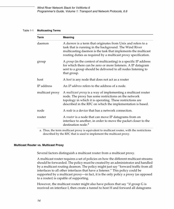
Table 1-1 lists the primary terms used to describe multicasting.
NOTE: The multicasting router and the multicast forwarding engine are only available in the Wind River Platforms builds of the network stack. The Wind River General Purpose Platform, VxWorks Edition, does not support the multicasting router.
NOTE: The router-side is not provided by the stack itself, but by a multicast daemon task, which implements the functionality of a multicast proxy.
Wind River Network Stack for VxWorks 6Programmer's Guide, Volume 1: Transport and Network Protocols, 6.6
14
Multicast Router vs. Multicast Proxy
Several factors distinguish a multicast router from a multicast proxy.
A multicast router requires a set of policies on how the different multicast streams should be forwarded. The policy must be created by an administrator and handled by a multicast routing deamon. The policy might just say “forward traffic from all interfaces to all other interfaces that have a listener.” This policy could be supported by a multicast proxy—in fact, it is the only policy a proxy (as opposed to a router) is capable of supporting.
However, the multicast router might also have polices that say “if group G is received on interface I, then create a tunnel to host H and forward all datagrams
Table 1-1 Multicasting Terms
Term Meaning
daemon A daemon is a term that originates from Unix and refers to a task that is running in the background. The Wind River multicasting daemon is the task that implements the multicast routing duties as required by a multicast proxy specification.
group A group (in the context of multicasting) is a specific IP address for which there can be zero or more listeners. A IP datagram sent to a group should be delivered to all nodes listening to that group.
host A host is any node that does not act as a router
IP address An IP address refers to the address of a node.
multicast proxy A multicast proxy is a way of implementing a multicast router node. The proxy has some restrictions on the network topology in which it is operating. These restrictions are described in the RFC on which the implementation is based.
node A node is a device that has a network connection.
router A router is a node that can move IP datagrams from on interface to another, in order to move the packet closer to the destination node.a
a. Thus, the term multicast proxy is equivalent to multicast router, with the restrictions described by the RFC that is used to implement the multicast proxy.
1 Overview1.3 Product Overview
15
1received on interface I to group G into that tunnel.” This behavior distinguishes a router from a proxy. A proxy cannot perform such a task.
Note that a proxy acts as a multicast router or host on a link. A specific node (i.e., a physical machine with networking capabilities) can act as a multicast host on some of its network interfaces while acting as a multicast router on others.
One restriction a multicast proxy has compared to a multicast router is that it cannot act as multicast router on all links. It must be a multicast host on at least one of its links and one of those links is the “upstream” interface.
On the routers serving the points in the network to which you want to multicast, you must run a common multicast routing protocol. On all VxWorks targets participating in the multicast, both senders and the receivers, you must enable multicast forwarding in the kernel, and you must run a multicast routing capable application.
Thus, the multicast proxy has the benefit of not requiring any policy configuration and would work very well in any office or home receiving multicast traffic from the Internet. The interface connected to the Internet would be the uplink interface.
One reason to use a multicast router is that many backbone routers on the Internet do not support multicast. For example, if a corporate office in Stockholm wanted to send a multicast stream to an office in Ottawa, it would need a multicast router that would create a unicast tunnel between these offices, which would handle all multicast traffic Stockholm and Ottowa. The offices could thus send a multicast stream between them since all the Internet backbone would do is forward unicast datagrams (which just happen to carry multicast traffic).
Multicast Router Components
The multicast router consists of three parts:
■ The control plane implements the server side of the IGMP and MLD protocols. It determines whether groups have listeners on a link.
■ The multicast routing table (also known as the forwarding information base, or FIB) programs the multicast routing table to route multicast traffic. It serves as the interface between the control plane and data plane.
■ The data plane receives multicast datagrams on an ingress interface and forwards them to zero or more egress interfaces according to the rules in the FIB.

Wind River Network Stack for VxWorks 6Programmer's Guide, Volume 1: Transport and Network Protocols, 6.6
16
Multicast Router Implementation
VxWorks implements the multicast router via a multicast proxy task, which waits on a message queue. This message queue collects expiration messages and membership reports. In response to a timer expiration message, the proxy either sends a query or removes a multicast destination from the interface on which it has expired.
In response to a membership report, the task processes the packet.
When a new membership report arrives on an interface, a placeholder entry is created in the FIB. Integration with other multicast protocols (such as PIM) is required to create completed entries that forward multicast traffic.
Multicast Proxy Implementation
The Wind River multicast proxy implementation is a limited implementation of the router part of the IGMP and MLD protocols. The first limitation is that the proxy must act as a multicast host on at least one of the interfaces. However, it can forward traffic between all downstream and upstream interfaces.
The other limitation is that it will always forward multicast datagrams to the upstream interface unless it was the ingress interface for the datagram. These restrictions are normally not a problem for routers used as home or corporate gateways, where the upstream interface would be the interface connected to the Internet. However, backbone multicast routers must use a full multicast router implementation.
The multicasting router end is implemented through a multicast router daemon, which keeps track of the groups (and channels, in the case of source-specific multicast) that have listeners, and programs the stack using the MRT_xxx family of setsockopt( ) (MRT6_xxx family for MLD). When the stack encounters multicast packets for which no routing policy exists, it generates events at the socket that called the MRT_INIT (or MRT6_INIT for MLD). For more information, see 7.6 Adding and Deleting Virtual Interfaces for Multicast Routing, p.147.
Multicast Proxy Operation
The multicast proxy handles:
■ the IPv6 multicast forwarding control plane
■ the MLD router side implementation
1 Overview1.3 Product Overview
17
1■ the IPv4 multicast forwarding control plane
■ the IGMP router side implementation
The actual forwarding—that is, moving an incoming multicast packet from, and interface to, zero or more outgoing packets—is done by the stack base, on the information programmed by the control plane (in this case, the multicast proxy task).
Operational Example
In this example, a node (called R) has three interfaces—I1, I2, and I3. IPMCP is configured to use I1 as the upstream interface and I2 and I3 as the downstream interfaces.
The network also has three multicast hosts:
■ H1 connected to the same link as I1■ H2 connected to I2■ H3 connected to I3
H1, H2, and H3 are not members of any groups at first.
R sends out periodical queries on I2 and I3 (since it acts as a multicast router on those interfaces) that ask: “to all nodes, tell me which multicast groups you are listening to on this link.” It receives no response at this point in the example.
H1 now sends a datagram to group G1. This datagram will not be received by R and not forwarded, because R is a multicast host on this link and is not listening to that group.
H2 now sends a datagram to group G2. This datagram will be received by R on I2 since a router receives all multicast datagrams. R forwards the datagram to I1—it cannot detect listeners on group G2 because it is not a router on that link. This is one of the restrictions of proxies compared to full multicast routers. All received multicast datagram has to be forwarded to the uplink interface, which could cause some unnecessary traffic on that link.
H1 now joins G2. This will result in an IGMP or MLD (depends on whether G is an IPv4 or an IPv6 address) that says “I've joined group G2.” R does not receive that report, and even if it did, it would just ignore it since it is acting as multicast host on I1.
H1 would now receive any datagram sent to G2 from H2 or H3, since all multicast packages are forwarded to the uplink interface.
H2 now joins G2. A report is sent and is processed by R since it acts as a router on I2. R now joins group G2 on its uplink interface I1. R therefore sends a report to

Wind River Network Stack for VxWorks 6Programmer's Guide, Volume 1: Transport and Network Protocols, 6.6
18
that link, which is not processed by H1 but may be processed by any multicast router on that link.
H3 send a datagram to G2. R receives it and forward its to both I1 and I2—I1 since it is the uplink interface and I2 because R knows that group G2 has (at least) one listener on the link attached to I2. Both H1 and H2 receive the datagram.
H1 send a datagram to G2. R receives it since it is now listening on that group on I1. R detects a listener for G2 on I2 and forwards the datagram out to that link. It does not send a copy to I1 since a multicast datagram is never forwarded to the interface it was received on.
H2 leaves G2, a report is sent that says “I'm no longer interested in group G2.” R sees the report and sends out a query to I2 that says “Is any node listening to group G2?” R will stop forwarding datagrams sent to G2 if no one answers that question within the timeout value set by the IPMCP configuration. The default value is 10 sec.
1.4 Additional Documentation
The following sections describe additional documentation about the technologies described in this book.
Wind River Documentation
The following Wind River documents present information associated with the Wind River Network Stack:
■ Wind River VxWorks Platforms Getting Started – describes how to install and build components of the Wind River VxWorks Platforms product.
■ Wind River VxWorks Platforms Release Notes – describes reported and resolved software defects and new features for the Wind River VxWorks Platforms product.
Wind River Network Stack Programmer's Guide
The Wind River Network Stack Programmer's Guide consists of three volumes. This is Volume 1. This volume provides an overview and general information about
1 Overview1.4 Additional Documentation
19
1about the network stack. In addition, it covers routing and the network and transport layers, including the following topics:
■ configuring a minimal stack
■ configuring and running the network daemon task
■ adding basic TCP/IP support for IPv4 and IPv6
■ adding Address Resolution Protocol (ARP)
■ using routing socket messages
■ adding RIP and RIPng support
■ working with the Virtual Router Redundancy Protocol (VRRP)
■ enabling virtual routers
■ Multiprotocol Label Switching (MPLS) - Data plane support
■ adding IGMP and MLD multicasting support for IPv4 and IPv6
■ configuring and using Mobile IP
Volume 2 of the Wind River Network Stack Programmer's Guide covers implementations of application-layer protocols and socket programming. The Wind River network stack includes implementations of the following application-layer protocols:
■ DHCP and DHCPv6■ DNS■ FTP■ Ping■ RLOGIN■ RPC■ RSH■ SNTP■ Telnet■ TFTP
Volume 3 of the Wind River Network Stack Programmer's Guide covers interfaces, drivers, and the MUX, which is an abstraction layer between the drivers and interfaces. Volume 3 includes the following topics:
■ configuring and managing network memory
■ creating and configuring network interfaces
■ using tunneling with interfaces
Wind River Network Stack for VxWorks 6Programmer's Guide, Volume 1: Transport and Network Protocols, 6.6
20
■ using router advertisement and solicitation
■ integrating END and Network Protocol Toolkit (NPT) driver interfaces
■ integrating a new network-layer or transport-layer service
■ using 802.1Q VLAN tagging
■ MUX/NPT routines and data structures.
■ implementing quality-of-service (QoS) mechanisms
Books
The focus of this manual is the configuration of the Wind River Network Stack. Although this manual includes some networking background information, it is beyond the scope of this manual to provide a thorough description of socket usage, routing, protocol implementation, writing a network interface driver, and interpreting statistics returned by routines. For information of that sort, consider the following sources:
■ The Design and Implementation of the 4.4 BSD Operating System, by Marshall Kirk McKusick, Keith Bostic, Michael J. Kraals, John S. Quarterman
■ TCP/IP Illustrated, Vol. 1, by Richard Stevens
■ TCP/IP Illustrated, Vol. 2, by Gary Wright and Richard Stevens
■ Internetworking with TCP/IP Volume III, by Douglas Comer and David Stevens.
■ UNIX Network Programming, by Richard Stevens (for information on socket programming)
■ Implementing IPv6, by Mark A. Miller, P.E.
Online Resources
Online resources are as follows:
■ The IPv6 Forum Web site, www.ipv6forum.com
■ The IPv6 Information Page, www.ipv6.org
1 Overview1.4 Additional Documentation
21
1RFCs
The Wind River Network Stack is compliant with the following RFCs, except where noted otherwise. These RFCs can be found at the IETF Web site http://www.ietf.org.
RFC 0147: Definition of a socket
RFC 0768: User Datagram Protocol
RFC 0781: Specification of the Internet Protocol (IP) timestamp option
RFC 0791: Internet Protocol
RFC 0792: Internet Control Message Protocol
RFC 0793: Transmission Control Protocol
RFC 0826: Ethernet Address Resolution Protocol: Or Converting Network Protocol Addresses to 48.bit Ethernet Address for Transmission on Ethernet Hardware
RFC 0894: A Standard for the Transmission of IP Datagrams over Ethernet Networks
RFC 0903: A Reverse Address Resolution Protocol
RFC 0919: Broadcasting Internet Datagrams
RFC 0922: Broadcasting Internet datagrams in the presence of subnets
RFC 0925: Multi-LAN Address Resolution
RFC 0950: Internet Standard Subnetting Procedure
RFC 0959: File Transfer Protocol (partial implementation; see Wind River Network Stack for VxWorks 6 Programmer’s Guide 6.6,Volume 2: Application Protocols, for further information)
RFC 1027: Using ARP to implement transparent subnet gateways
RFC 1034: Domain Names - Concepts and Facilities (partial implementation; see Wind River Network Stack for VxWorks 6 Programmer’s Guide 6.6,Volume 2: Application Protocols, for further information)
RFC 1035: Domain Names - Implementation and Specification (partial implementation; see Wind River Network Stack for VxWorks 6 Programmer’s Guide 6.6,Volume 2: Application Protocols, for further information)
RFC 1058: Routing Information Protocol
RFC 1071: Computing the Internet checksum
RFC 1112: Host extensions for IP multicasting
Wind River Network Stack for VxWorks 6Programmer's Guide, Volume 1: Transport and Network Protocols, 6.6
22
RFC 1122: Requirements for Internet Hosts - Communication Layers
RFC 1123: Requirements for Internet Hosts - Application and Support
RFC 1123: Requirements for Internet Hosts - Application and Support
RFC 1191: Path MTU discovery
RFC 1256: ICMP Router Discovery Messages
RFC 1323: TCP Extensions for High Performance
RFC 1349: Type of Service in the Internet Protocol Suite
RFC 1350: The TFTP Protocol (Revision 2)
RFC 1517: Applicability Statement for the Implementation of Classless Inter-Domain Routing CIDR
RFC 1518: An Architecture for IP Address Allocation with CIDR
RFC 1519: Classless Inter-Domain Routing (CIDR): an Address Assignment and Aggregation Strategy
RFC 1624: Computation of the Internet Checksum via Incremental Update
RFC 1701: Generic Routing Encapsulation (GRE)
RFC 1724: RIP Version 2 MIB Extension
RFC 1853: IP in IP Tunneling
RFC 1853: IP in IP Tunnelling
RFC 1886: DNS Extensions to support IP version 6
RFC 1924: A Compact Representation of IPv6 Addresses
RFC 1981: Path MTU Discovery for IP version 6
RFC 2001: TCP Slow Start, Congestion Avoidance, Fast Retransmit, and Fast Recovery Algorithms
RFC 2002: IP Mobility Support
RFC 2003: IP Encapsulation within IP
RFC 2004: Minimal Encapsulation within IP
RFC 2005: Applicability Statement for IP Mobility Support
RFC 2018: TCP Selective Acknowledgment Options
RFC 2030: Simple Network Time Protocol (SNTP) Version 4 for IPv4, IPv6 and OSI

1 Overview1.4 Additional Documentation
23
1RFC 2104: HMAC: Keyed-Hashing for Message Authentication
RFC 2113: IP Router Alert Option
RFC 2236: Internet Group Management Protocol, Version 2
RFC 2373: IP Version 6 Addressing Architecture
RFC 2374: An IPv6 Aggregatable Global Unicast Address Format
RFC 2375: IPv6 Multicast Address Assignments
RFC 2385: Protection of BGP Sessions via the TCP MD5 Signature Option
RFC 2401: Security Architecture for the Internet Protocol
RFC 2406: IP Encapsulating Security Payload (ESP)
RFC 2428: FTP Extensions for IPv6 and NATs
RFC 2450: Proposed TLA and NLA Assignment Rule
RFC 2453: RIP Version 2
RFC 2460: Internet Protocol, Version 6 (IPv6) Specification
RFC 2461: Neighbor Discovery for IP Version 6 (IPv6)
RFC 2462: IPv6 Stateless Address Autoconfiguration
RFC 2463: Internet Control Message Protocol (ICMPv6) for the Internet Protocol Version 6 (IPv6) Specification
RFC 2463: Internet Control Message Protocol (ICMPv6) for the Internet Protocol Version 6 (IPv6) Specification
RFC 2464: Transmission of IPv6 Packets over Ethernet Networks
RFC 2473: Generic Packet Tunneling in IPv6 Specification
RFC 2473: Generic Packet Tunnelling in IPv6 Specification
RFC 2474: Definition of the Differentiated Services Field (DS Field) in the IPv4 and IPv6 Headers
RFC 2475: An Architecture for Differentiated Service
RFC 2529: Transmission of IPv6 over IPv4 Domains without Explicit Tunnels
RFC 2529: Transmission of IPv6 over IPv4 Domains without Explicit Tunnels
RFC 2547: BGP/MPLS VPNs
RFC 2553: Basic Socket Interface Extensions for IPv6

Wind River Network Stack for VxWorks 6Programmer's Guide, Volume 1: Transport and Network Protocols, 6.6
24
RFC 2553: Basic Socket Interface Extensions for IPv6
RFC 2577: FTP Security Considerations
RFC 2581: TCP Congestion Control
RFC 2597: Assured Forwarding PHB Group
RFC 2697: A Single Rate Three Color Marker
RFC 2710: Multicast Listener Discovery (MLD) for IPv6
RFC 2711: IPv6 Router Alert Option
RFC 2784: Generic Routing Encapsulation (GRE)
RFC 2794: Mobile IP Network Access Identifier Extension for IPv4
RFC 2893: Transition Mechanisms for IPv6 Hosts and Routers
RFC 2977: Mobile IP Authentication, Authorization, and Accounting Requirements
RFC 2991: Multipath Issues in Unicast and Multicast Next-Hop Selection
RFC 3012: Mobile IPv4 Challenge/Response Extensions
RFC 3024: Reverse Tunneling for Mobile IP, revised
RFC 3031: Multiprotocol Label Switching Architecture
RFC 3041: Privacy Extensions for Stateless Address Autoconfiguration in IPv6
RFC 3056: Connection of IPv6 Domains via IPv4 Clouds
RFC 3056: Connection of IPv6 Domains via IPv4 Clouds
RFC 3115: Mobile IP Vendor/Organization-Specific Extensions
RFC 3315: Dynamic Host Configuration Protocol for IPv6 (DHCPv6) (partial implementation; see Wind River Network Stack for VxWorks 6 Programmer’s Guide 6.6,Volume 2: Application Protocols, for further information)
RFC 3344: IP Mobility Support for IPv4
RFC 3376: Internet Group Management Protocol, Version 3
RFC 3484: Default Address Selection for Internet Protocol version 6 (IPv6)
RFC 3493: Basic Socket Interface Extensions for IPv6
RFC 3513: Internet Protocol Version 6 (IPv6) Addressing Architecture
RFC 3519: Mobile IP Traversal of Network Address Translation (NAT) Devices
RFC 3542: Advanced Sockets Application Program Interface (API) for IPv6
1 Overview1.4 Additional Documentation
25
1RFC 3543: Registration Revocation in Mobile IPv4
RFC 3587: IPv6 Global Unicast Address Format
RFC 3596: DNS Extensions to Support IP Version 6
RFC 3646: DNS Configuration options for Dynamic Host Configuration Protocol for IPv6 (DHCPv6)
RFC 3678: Socket Interface Extensions for Multicast Source Filters
RFC 3736: Stateless Dynamic Host Configuration Protocol (DHCP) Service for IPv6
RFC 3768: Virtual Router Redundancy Protocol (VRRP)
RFC 3769: Requirements for IPv6 Prefix Delegation
RFC 3775: Mobility Support in IPv6 (partial implementation; see Wind River Network Stack for VxWorks 6 Programmer’s Guide 6.6,Volume 3: Interfaces and Drivers, for further information)
RFC 3776: Using IPsec to Protect Mobile IPv6 Signaling Between Mobile Nodes and Home Agents
RFC 3810: Multicast Listener Discovery Version 2 (MLDv2) for IPv6
RFC 3846: Mobile IPv4 Extension for Carrying Network Access Identifiers
RFC 3879: Deprecating Site Local Addresses
RFC 3927: Dynamic Configuration of IPv4 Link-Local Addresses
RFC 4075: Simple Network Time Protocol (SNTP) Configuration Option for DHCPv6
RFC 4193: Unique Local IPv6 Unicast Addresses
RFC 4213: Basic Transition Mechanisms for IPv6 Hosts and Routers (does not implement the optional (MAY) feature described in 3.2.2., Dynamic Tunnel MTU)
RFC 4242: Information Refresh Time Option for Dynamic Host Configuration Protocol for IPv6 (DHCPv6)
RFC 4291: IP Version 6 Addressing Architecture
RFC 4293: Management Information Base for the Internet Protocol (IP)
RFC 4294: IPv6 Node Requirements
RFC 4433: Mobile IPv4 Dynamic Home Agent (HA) Assignment
RFC 4443: Internet Control Message Protocol (ICMPv6) for the Internet Protocol Version 6 (IPv6) Specification
Wind River Network Stack for VxWorks 6Programmer's Guide, Volume 1: Transport and Network Protocols, 6.6
26
RFC 4604: Using Internet Group Management Protocol Version 3 (IGMPv3) and Multicast Listener Discovery Protocol Version 2 (MLDv2) for Source-Specific Multicast
RFC 4605: Internet Group Management Protocol (IGMP) / Multicast Listener Discovery (MLD)-Based Multicast Forwarding ("IGMP/MLD Proxying") The operation of a multicast proxy is described in RFC 4605. The Wind River multicast proxy implements the server part of the RFCs listed in this section.
RFC 4607: Source-Specific Multicast for IP
RFC 4636: Foreign Agent Error Extension for Mobile IPv4
RFC 4692: Considerations on the IPv6 Host Density Metric
Related RFCs
RFC 0854: Telnet Protocol Specification
RFC 0951: Bootstrap Protocol
RFC 1014: XDR: External Data Representation standard
RFC 1542: Clarifications and Extensions for the Bootstrap Protocol
RFC 1700: Assigned Numbers
RFC 1831: RPC: Remote Procedure Call Protocol Specification Version 2
RFC 2131: Dynamic Host Configuration Protocol
RFC 2132: DHCP Options and BOOTP Vendor Extensions
RFC 2242: NetWare/IP Domain Name and Information
RFC 2849: The LDAP Data Interchange Format (LDIF) - Technical Specification
RFC 3152: Delegation of IP6.ARPA
RFC 3232: Assigned Numbers: RFC 1700 is Replaced by an On-line Database
RFC 3633: IPv6 Prefix Options for Dynamic Host Configuration Protocol (DHCP) version 6

27
2Configuring and Building the
Network Stack
2.1 Introduction 27
2.2 Configuring and Building the Wind River Network Stack Source Code 28
2.3 Configuring VxWorks with the Wind River Network Stack 32
2.4 Using Shell Commands 45
2.5 Testing Connectivity from the Target 49
2.1 Introduction
This chapter provides information on the following topics:
■ how to build a VxWorks bootable image that includes a basic network stack without security components for use in applications where footprint size is a concern
■ how to access shell commands that can be used to configure the network stack
■ how to configure the network daemon task
The following chapters also provide additional detail:
■ 3. Configuring Transport and Network Protocols explains how to implement the protocols ARP, UDP, TCP/IP, ICMP, NDP, and MPLS.
Wind River Network Stack for VxWorks 6Programmer's Guide, Volume 1: Transport and Network Protocols, 6.6
28
■ 4. Adding Routing Support describes the route storage mechanism and the protocols used to maintain the contents of the route table.
■ 5. Working with Routing Sockets describes how to configure and build routing sockets, which provide a two-way interface to the routing table.
■ 6. Enabling Virtual Routers describes the use of virtual routing tables, which ensure the multiplication of routing tables while minimizing the demand on system resources.
■ 7. Adding Support for Multicast Routing describes how to configure and build support for multicast routing.
■ Chapters 8–12 describe how to configure and build Mobile IP.
2.2 Configuring and Building the Wind River Network Stack Source Code
The Platform getting started guide contains general instructions for building a product into VxWorks. This section describes some options for building the network stack source.
2.2.1 IPv4 or IPv6
You can build the network stack source code in one of three ways:
■ IPv4 only■ IPv4/IPv6■ IPv6 only
The procedure you follow depends on your installation. For further information, see either Wind River VxWorks Platforms, p.29, or Wind River General Purpose Platform, VxWorks Edition, p.30.
Affected Modules—IPv6-Only Network Stack
Most code modules are unaffected by the way the network stack source code is built. If you build an IPv6-only network stack, however, modifications may be
2 Configuring and Building the Network Stack2.2 Configuring and Building the Wind River Network Stack Source Code
29
2
required in modules that make calls to IPv4 routines. Such modules include SNMP and BSPs.
To make these modules compatible with an IPv6-only network stack, perform the following steps:
■ Enclose any IPv4-specific code with #ifdef INET.
■ Enclose any IPv6-specific code fragment with #ifdef INET6.
Build Instructions
Wind River VxWorks Platforms
The macro settings in the config.mk file in the installDir/vxworks-6.x/config/platform directory determine how the network stack is built.
By default, the network stack is built for IPv4:
export FEATURE_IPNET_INET6 = false
To build the network stack for combined IPv4/IPv6 support, set this macro to true.
An additional macro is available for building an IPv6-only network stack. By default, this macro is set to false.
export FEATURE_IPNET_INET6_ONLY = false
To build an IPv6-only network stack, set this macro to true.
Whenever you change these values, you must rebuild the Platform source code as described in your Platform getting started guide.
If you build an IPv6-only network stack, however, you must also disable certain components before building the Platform source code. These components include:
■ COMPONENT_SNMP ■ COMPONENT_IPIPSEC■ COMPONENT_IPIKE■ COMPONENT_IPFREESCALE■ COMPONENT_IPSSH■ COMPONENT_IPMIP4■ COMPONENT_IPMIPFA■ COMPONENT_IPMIPHA■ COMPONENT_IPMIPMN■ COMPONENT_IPEAP■ COMPONENT_IPDIAMETERC
Wind River Network Stack for VxWorks 6Programmer's Guide, Volume 1: Transport and Network Protocols, 6.6
30
■ COMPONENT_IPSSL■ COMPONENT_IPCRYPTO■ COMPONENT_IPRIPNG■ COMPONENT_IPMIP6■ COMPONENT_IPMIP6MN■ COMPONENT_PPP■ COMPONENT_DOT1X■ COMPONENT_RADIUS■ COMPONENT_FIREWALL■ COMPONENT_WLAN
Wind River General Purpose Platform, VxWorks Edition
In Wind River General Purpose Platform, VxWorks Edition, the source code libraries are prebuilt for an IPv4-only network stack.
To rebuild the source code libraries with support for a dual IPv4/IPv6 network stack, you must issue a make command with the ADDED_Cflags+=-DINET6 command-line flag.
To rebuild the source code libraries with support for an IPv6-only network stack, you must issue a make command in the following directory:
installDir/vxworks-6.x/target/src/ipnet
Use the ADDED_Cflags+=-DINET6_ONLY command-line flag:
make CPU=cpuType TOOL=toolChain ADDED_CFLAGS+=-DINET6_ONLY
Symbol Table Download and Network Drives
Symbol table download and network drive mounting are ordinarily performed over an IPv4 network. Some modifications may be required when you build an IPv6-only network stack. For further information, see 2.3.2 Special Provisions for IPv6-Only Network Stacks, p.40.
NOTE: Certain third-party libraries are supplied only in binary format, without source code. You must back up these libraries before rebuilding the VxWorks source code. For a complete description of the procedures for backing up prebuilt libraries and rebuilding the source code, see the getting started guide for Wind River General Purpose Platform, VxWorks Edition.
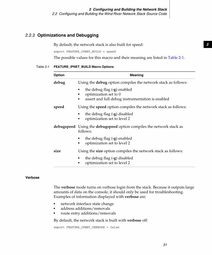
2 Configuring and Building the Network Stack2.2 Configuring and Building the Wind River Network Stack Source Code
31
2
2.2.2 Optimizations and Debugging
By default, the network stack is also built for speed:
export FEATURE_IPNET_BUILD = speed
The possible values for this macro and their meaning are listed in Table 2-1.
Verbose
The verbose mode turns on verbose login from the stack. Because it outputs large amounts of data on the console, it should only be used for troubleshooting. Examples of information displayed with verbose are:
■ network interface state change■ address additions/removals■ route entry additions/removals
By default, the network stack is built with verbose off:
export FEATURE_IPNET_VERBOSE = false
Table 2-1 FEATURE_IPNET_BUILD Macro Options
Option Meaning
debug Using the debug option compiles the network stack as follows:
■ the debug flag (-g) enabled■ optimization set to 0■ assert and full debug instrumentation is enabled
speed Using the speed option compiles the network stack as follows:
■ the debug flag (-g) disabled■ optimization set to level 2
debugspeed Using the debugspeed option compiles the network stack as follows:
■ the debug flag (-g) enabled■ optimization set to level 2
size Using the size option compiles the network stack as follows:
■ the debug flag (-g) disabled■ optimization set to level 2
Wind River Network Stack for VxWorks 6Programmer's Guide, Volume 1: Transport and Network Protocols, 6.6
32
To build the stack to turn verbose on, set this macro to true:
export FEATURE_IPNET_VERBOSE = true
and rebuild the stack.
2.2.3 SMP Platform Build
To build the Platform source for SMP, add VXBUILD=SMP to the make command. For example:
make CPU=cpuType TOOL=toolChain VXBUILD=SMP
2.2.4 Examples
For example, with the following settings:
FEATURE_IPNET_BUILD = debug FEATURE_IPNET_VERBOSE = true
the source is built with the debug messages incorporated into the build, and they get printed onto the console, from the vxWorks image loaded onto the target.
The same can also be achieved by the following :
make CPU=PENTIUM4 TOOL=diab FEATURE_SET=pne IPBUILD=debug IPVERBOSE=yes TARGET=rclean
make CPU=PENTIUM4 TOOL=diab FEATURE_SET=pne IPBUILD=debug IPVERBOSE=yes
2.3 Configuring VxWorks with the Wind River Network Stack
This section lists the minimal network components needed to create a stack with just enough resources to respond to a ping or ping6 request. This lets a remote system test the network connection to your target. Since, you cannot test network connectivity from a target running a minimal stack without adding ping, ping or ping6 are also included in the list of essential components.
You can configure VxWorks in either of two ways—with the Wind River Workbench or the vxprj command-line tool. Both methods handle dependencies for you. For instructions on using Workbench, see the Wind River Workbench User's
2 Configuring and Building the Network Stack2.3 Configuring VxWorks with the Wind River Network Stack
33
2
Guide. For instructions on using vxprj, see the VxWorks Command-Line Tools User's Guide.
If a component contains configuration parameters, you may need or want to modify them.
Creating an IPv6 Project
If you are using the General Purpose Platform and creating an IPv6-compatible network stack, you must specify an additional option when you create your project.
■ If you are using Workbench, select Use IPv6 enabled kernel libraries in the Options page of the New VxWorks Image Project wizard.
■ If you are using vxprj, add the flag -inet6 to the make command.
Creating an SMP Project
If you are creating an SMP-compatible network stack, you must specify this option when you create your project.
■ If you are using Workbench, select Build with SMP options in the Options page of the New VxWorks Image Project wizard.
■ If you are using vxprj, add the flag -smp to the make command.
Automatically Included Components
The components listed in this section are required, but are automatically included when a project is created, so you do not need to explicitly add them.
INCLUDE_IPNET
This component automatically includes the INCLUDE_IPCOM component, which pulls in the socket library (INCLUDE_SOCKLIB) and the common networking infrastructure (INCLUDE_COMMON_NET and INCLUDE_IPNET_STACK). It also
NOTE: This option is only applicable for network stack projects based on the General Purpose Platform. Do not specify this option if you are using the Wind River VxWorks Platforms.
Wind River Network Stack for VxWorks 6Programmer's Guide, Volume 1: Transport and Network Protocols, 6.6
34
includes support for the routing network stack, the networking daemon, the MUX and END drivers, job queuing, and memory pool buffers.
INCLUDE_IPCOM_USE_INET
This component pulls in UDPv4 and ICMPv4, as well as the standard support for IPv4.
INCLUDE_IPTCP
This component pulls in libraries and modules that provide support for TCP in either the IPv4 or IPv6 domains. Which support is included depends on how the network stack source is built. For more information, see your Platform getting started guide.
Additionally Required Components
The components listed in this section are required. In most cases, they are included when you build a VxWorks image.
INCLUDE_GTF_TIMER_START
This component automatically starts the General Timer Facility. This component requires INCLUDE_GTF, which pulls in modules that support the General Timer Facility. INCLUDE_GTF has no configuration parameters.
INCLUDE_GTF_TIMER_START has no configuration parameters.
INCLUDE_INETLIB
This component pulls in inetLib and other modules that implement routines for manipulating Internet addresses, including the UNIX BSD inet_ routines. It includes routines for converting between character addresses in Internet standard dotted decimal notation and integer addresses, routines for extracting the network and host portions out of an Internet address, and routines for constructing Internet addresses given the network and host address parts.
There are no component dependencies or configuration parameters associated with this component. For information on the externally callable functions associated with this component, see the inetLib reference entry.
2 Configuring and Building the Network Stack2.3 Configuring VxWorks with the Wind River Network Stack
35
2
INCLUDE_IPATTACH or INCLUDE_IP6ATTACH
This component provides ipAttach( ) or ip6Attach( ) for attaching to the network interface specified in the boot line parameters.
INCLUDE_IPCOM_USE_ETHERNET
This component pulls in Ethernet support and denotes the type of link layer interface to support.
INCLUDE_IPPING_CMD or INCLUDE_IPPING6_CMD
These components pull in the modules for ping or ping6, respectively. If you want to run an application, you probably want the default stack components (at the very least), which also include INCLUDE_APPL_LOG_UTIL.
INCLUDE_NET_BOOT_CONFIG
This component configures a network interface based on the device configuration parameters in the boot line. This component has no associated configuration parameters.
INCLUDE_NET_REM_IO
This component pulls in modules that initialize systems in support of file access on the boot host. This component supports the activities of components such as INCLUDE_NET_DRV and requires the following components:
■ INCLUDE_NET_DRV■ INCLUDE_BOOT_LINE_INIT■ INCLUDE_NET_BOOT■ INCLUDE_NET_HOST_SETUP
For more information on how to use netDrv, see the netDrv reference entry.
NOTE: The return values of inet_aton are not compatible with some other BSD socket implementations. inet_aton returns 0K for success or ERROR for failure, whereas vxworks.h defines OK as 0 and ERROR as (-1).
Like other BSD implementations, the internal API ipcom_inet_aton returns -1 for success and 0 for failure. However, to maintain backwards compatibility for VxWorks socket applications, these values have been reversed by the public wrapper code inet_aton.
Wind River Network Stack for VxWorks 6Programmer's Guide, Volume 1: Transport and Network Protocols, 6.6
36
INCLUDE_NET_SYSCTL
This component pulls in the sysctlLib module and adds network system control support. This component requires INCLUDE_SYSCTL and has no configuration parameters.
INCLUDE_PING
This component pulls in support for the ping utility with IPv4 and is documented in the Wind River Network Stack for VxWorks 6 Programmer’s Guide, Volume 2.
INCLUDE_PING6
This component pulls in support for the ping utility with IPv6 and is documented in the Wind River Network Stack for VxWorks 6 Programmer’s Guide, Volume 2. This component is only required for an IPv6 stack.
INCLUDE_XDR
This component pulls in modules that implement generic XDR (External Data Representation) routines. It is automatically included as a requirement for Remote Procedure Call (RPC).
This component is required only if you also include WDB_COMM_SERIAL. For more information, see the Wind River Network Stack for VxWorks 6 Programmer’s Guide, Volume 2.
2.3.1 Including a Network Driver
To make the stack usable, it must include at least one network driver.
The following sections describe how to add and configure the necessary interfaces.
Which procedure you follow depends on whether your BSP supports VxBus. If it does, the system will automatically detect any additional drivers, and you only need to configure them. In such a case, perform only the procedure described in Configuring an Additional Interface, p.38.
Checking for VxBus Support
You can tell whether your BSP supports VxBus by examining the following file:
target/config/bspName/config.h
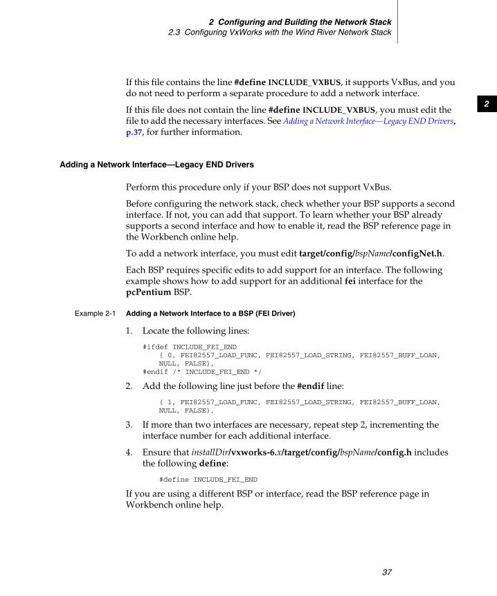
2 Configuring and Building the Network Stack2.3 Configuring VxWorks with the Wind River Network Stack
37
2
If this file contains the line #define INCLUDE_VXBUS, it supports VxBus, and you do not need to perform a separate procedure to add a network interface.
If this file does not contain the line #define INCLUDE_VXBUS, you must edit the file to add the necessary interfaces. See Adding a Network Interface—Legacy END Drivers, p.37, for further information.
Adding a Network Interface—Legacy END Drivers
Perform this procedure only if your BSP does not support VxBus.
Before configuring the network stack, check whether your BSP supports a second interface. If not, you can add that support. To learn whether your BSP already supports a second interface and how to enable it, read the BSP reference page in the Workbench online help.
To add a network interface, you must edit target/config/bspName/configNet.h.
Each BSP requires specific edits to add support for an interface. The following example shows how to add support for an additional fei interface for the pcPentium BSP.
Example 2-1 Adding a Network Interface to a BSP (FEI Driver)
1. Locate the following lines:
#ifdef INCLUDE_FEI_END{ 0, FEI82557_LOAD_FUNC, FEI82557_LOAD_STRING, FEI82557_BUFF_LOAN,NULL, FALSE},
#endif /* INCLUDE_FEI_END */
2. Add the following line just before the #endif line:
{ 1, FEI82557_LOAD_FUNC, FEI82557_LOAD_STRING, FEI82557_BUFF_LOAN,NULL, FALSE},
3. If more than two interfaces are necessary, repeat step 2, incrementing the interface number for each additional interface.
4. Ensure that installDir/vxworks-6.x/target/config/bspName/config.h includes the following define:
#define INCLUDE_FEI_END
If you are using a different BSP or interface, read the BSP reference page in Workbench online help.
Wind River Network Stack for VxWorks 6Programmer's Guide, Volume 1: Transport and Network Protocols, 6.6
38
Configuring an Additional Interface
Once you have added a network interface, you must configure it with an IP address or network mask. You can configure the interface at build time or at run time.
Configuring an Additional Interface at Build Time
To configure an interface at build time, include an INCLUDE_IPNET_IFCONFIG_N component (one for each interface). Each of these components contains an IFCONFIG_N parameter.
For each IFCONFIG_N, edit the following fields:
ifnameSpecifies the name of the Ethernet interface, for example, ifname fei0. If the interface name is missing after ifname (the default setting), the END device name will be used.
devnameSpecifies the driver to which this interface should attach itself, for example, fei0. The default setting driver instructs VxWorks to retrieve the device name from the device boot parameters.
inetSpecifies the interface IPv4 address and subnet, for example, inet 10.1.2.100/24. Instead of IPv4 address, the following syntaxes can also be used:
inet driver (default)Specifies that the address and mask should be read from the BSP.
inet dhcpSpecifies that the address and mask should be received from a DHCP server. The gateway might also be received from that server (depending on the DHCP server configuration).
inet rarpSpecifies that the address and mask should be received from an RARP server.
gatewaySpecifies the default gateway used for IPv4, for example, gateway 10.1.2.1. Only one default gateway can be specified. gateway driver can be used to take the gateway from the boot parameters.

2 Configuring and Building the Network Stack2.3 Configuring VxWorks with the Wind River Network Stack
39
2
inet6Specifies the interface IPv6 address and subnet, for example, inet6 3ffe:1:2:3::4/64. The tentative keyword can be inserted before the address if the stack should perform duplicate address detection on the address before assigning it to the interface, for example, tentative 3ffe:1:2:3::4/64.
gateway6Specifies the default gateway used for IPv6. Only one default gateway can be specified.
Configuring an Additional Interface by Editing config.h
You can also configure an additional interface by editing the config.h file for your BSP—that is, target/config/bspName/config.h. In this case, specify the values for IFCONFIG_N directly in the file, using a #define statement. For example:
#define IFCONFIG_1 "ifname", "devname driver","inet driver","gateway driver", \ "inet6 3ffe:1:2:3::10/64"
Configuring an Additional Interface at Run Time
If you are not ready to configure the interface at build time, you can configure it at run time. This procedure consists of two steps:
1. Attaching a protocol.
2. Configuring the address and subnet mask.
To perform these steps, run an ipAttach shell command on the target, followed by an ifconfig. For example:
[vxWorks *] # ipAttach 1,"fei"[vxWorks *] # ifconfig "fei1 10.0.0.2 netmask 255.255.255.0 up"
The parameters for the ifconfig command are specified in Configuring an Additional Interface at Build Time, p.38.
Creating a Tunnel to a Remote IPv6 Destination
In addition, for IPv6, you may want to set up a tunnel to a remote IPv6 destination if no IPv6 router is available locally. For information on how to do this at run-time, see the Wind River Network Stack for VxWorks 6 Programmer’s Guide, Volume 3.
Wind River Network Stack for VxWorks 6Programmer's Guide, Volume 1: Transport and Network Protocols, 6.6
40
2.3.2 Special Provisions for IPv6-Only Network Stacks
Downloading a symbol table and mounting network drives are ordinarily performed over an IPv4 network stack. If you build an IPv6-only network stack as described in 2.2.1 IPv4 or IPv6, p.28, you must make special provisions for these tasks.
The default VxWorks image is configured to support symbol table download over IPv6 if the network stack is built with the IPv6-only configuration. Therefore, do not undefine INCLUDE_NET_DRV in your BSP’s config.h or exclude INCLUDE_NET_DRV from the VxWorks image project. These steps disable symbol table download.
To download a symbol table at startup using the default image, you must only ensure that IPv6-related parameters are configured in the boot string as described below.
Configuring IPv6-Related Parameters at Boot Time
For an IPv6-only target to download the symbol table, you must provide the IPv6 address of the boot host. If the provided address is a global address, you must also provide the target’s boot interface global IPv6 address.
Because the inet on ethernet and host inet fields of the boot string are already used to configure the boot net device, you must use the other field for IPv6 addresses. The format of the other field is described below.
The format takes into the consideration the fact that the other field is also used to store the name of the interface that is initialized when the target is booted via non-network boot devices, such as SCSI, TFFS, etc.
If the target is booted via non-network devices and you want to initialize a network device, place its name at the beginning. Any subsequent configuration parameters must be followed by the semicolon (;) character (OTHER_FIELD_DELIMITER). This practice is based upon the covention used by TIPC.
The target IPv6 address field starts with ead6= and is followed by the IPv6 address string. This field is not required for symbol table download if you are using a link local address for the host.
The host IPv6 address field starts with had6= and is followed by the IPv6 address string. If the host IPv6 address is a link local address, note the following:
2 Configuring and Building the Network Stack2.3 Configuring VxWorks with the Wind River Network Stack
41
2
■ The address should be immediately followed by %ifname, where ifname is the name of the interface connected to the boot host.
■ The link local address is not readily available for routing because of initialization issues. Depending upon the network traffic in the LAN and other factors, the symbol table download could either be slow or even fail. To avoid failure, increase the number of connection retrials using the configuration parameter REM_NUM_CONN_RETRIALS. On a pcPentium target directly connected to a FreeBSD server with relatively small traffic, a 100% success rate was achieved if REM_NUM_CONN_RETRIALS==3. With this parameter set to 0, the success rate was 0. A succes rate of 60-90 percent was achieved with REM_NUM_CONN_RETRIALS set to 1 and 2.
2.3.3 Additional Dependencies
A minimal stack to which you have added the components listed in this chapter will support a ping or ping6 made from the stack using the host shell. However, you cannot use the kernel shell because that feature is not part of the minimal default stack, although you can add it in if you want. See 2.4.1 Including Shell Command Components, p.45, for further information.
2.3.4 Configuring the Network Daemon Task
Under VxWorks, the task tNet0 is the default network daemon. This task is dedicated to handling the task-level (as opposed to interrupt-level) processing required by the network stack; it is primarily used by network drivers. The ISR associated with a network driver uses jobQueuePost( ) to queue packet-processing work on this task. For information on using this function in an END or NPT driver, see the Wind River Network Stack for VxWorks 6 Programmer’s Guide, Volume 3.
To configure one or more network daemons, use the INCLUDE_NET_DAEMON component. This component supplies parameters that you can use to specify the
NOTE: If you include the DNS client, or resolver, INCLUDE_IPDNSC, you need to specify configuration values that are appropriate for your environment. The default values are mere placeholders. They allow a build to succeed, but they do not result in a working DNS resolver. For more information, see the Wind River Network Stack for VxWorks 6 Programmer’s Guide, Volume 2.
Wind River Network Stack for VxWorks 6Programmer's Guide, Volume 1: Transport and Network Protocols, 6.6
42
network task priority, stack size, and task options. This component also lets you control the size of the daemon job queues.
When there is just one network task in VxWorks, it is named tNet0. When there are several, the tasks are named as follows:
■ tNet0■ tNet1■ tNet2■ etc.
Configure the number of network tasks (network daemons) by means of the configuration parameter NUM_NET_DAEMONS of the INCLUDE_NET_DAEMON component. For any value of NUM_NET_DAEMONS other than 0, that value is the number of network tasks. A NUM_NET_DAEMONS value of 0 is a special case:
■ On a uniprocessor system, the value 0 means 1 network daemon is created.
■ On an SMP system, the value 0 means that N+1 network daemons are created, where N is the number of configured cores.
The daemons have no CPU affinity by default. If the NET_DAEMONS_CPU_AFFINITY parameter is TRUE on an SMP system, any network daemon whose index matches the index of a configured CPU will have affinity for that CPU.
As an example, if NUM_NET_DAEMONS is set to 0 on a four-core system, the following network daemons are created:
■ tNet0■ tNet1■ tNet2■ tNet3■ tNet4
If, in addition, NET_DAEMONS_CPU_AFFINITY is set to TRUE, then:
■ tNet0 has affinity to CPU 0.■ tNet1 has affinity to CPU 1.■ tNet2 has affinity to CPU 2.■ tNet3 has affinity to CPU 3.■ tNet4 has no CPU affinity.
NOTE: Using several network tasks is not a default for either a uniprocessor or SMP system. It would be rare, but not impossible, to use several network tasks on a UP system.
2 Configuring and Building the Network Stack2.3 Configuring VxWorks with the Wind River Network Stack
43
2
If NET_DAEMONS_CPU_AFFINITY is FALSE (the default), all the network daemons are created with no CPU affinity.
It is of course possible to modify the affinity of the CPU network daemon tasks in any way desired after creation.
By default, all END interfaces post work to the job queue serviced by the default network daemon tNet0. However, It is possible (at run time) to change the network daemon job queue that a VxBus END device posts work to, using the vxbEndQnumSet( ) function. This may improve performance for some SMP applications that communicate via multiple network interfaces concurrently. For more information on using the vxbEndQnumSet( ) utility, see the Wind River Network Stack for VxWorks 6 Programmer’s
Guide, Volume 3: Integrating a New Network Interface Driver.
Table 2-2 lists the INCLUDE_NET_DAEMON configuration parameters.
Table 2-2 Network Daemon Configuration Parameters
Name and Description Valid and Default Values
NET_TASK_OPTIONS Options specified in the taskSpawn( ) call for tNetn tasks.
VX_SUPERVISOR_MODE |VX_UNBREAKABLE
NET_DAEMONS_CPU_AFFINITYSpecifies whether network daemons have affinity for a particular CPU. When this option is set to TRUE, any network daemon whose index matches the index of a configured CPU will have affinity for that CPU.
FALSE
NET_TASK_PRIORITYTask priority for tNetn tasks.
Default: 50
NET_TASK_STACKSIZE Stack size for tNetn tasks.
Default: 10000
Wind River Network Stack for VxWorks 6Programmer's Guide, Volume 1: Transport and Network Protocols, 6.6
44
For the most part, you should not need to adjust any of these parameters. If you think you need to adjust the task priority consider the following. By default, tNetn runs at a priority of 50. If you launch a task that depends on network services, make sure your new task runs at a lower priority than that of tNetn.1
When assigning a priority to a task dependent upon network services, keep in mind the following:
■ An ISR interrupts even a priority 0 task.
■ When tNet0 is the highest priority task ready to run, it runs.
■ If a user task with a priority greater than tNet0 is ready, it runs instead of tNet0.2
■ While tNet0 does not run, packets are not processed, although packets may continue to arrive.
You must also consider the hazards of priority inversion. After a task takes a semaphore with priority inversion protection, its task priority is elevated if another higher priority task tries to take the semaphore. The new task priority is equal to that of the highest priority task waiting for the semaphore. This priority elevation is temporary. The priority of the elevated task drops back down to its normal level after it releases the semaphore with priority inversion protection.
If a task dependent on tNet0 takes a semaphore with priority inversion protection, and if a higher priority task subsequently tries to take the same semaphore, the tNet0-dependent task inherits the higher task priority. Thus, it is possible for a
NUM_NET_DAEMONSThe number of network tasks.
Default: 1
NET_JOB_NUM_CFGThe number of jobs allowed in the network daemon queue.
Default: 85
Table 2-2 Network Daemon Configuration Parameters (cont’d)
Name and Description Valid and Default Values
1. Changes to the TFTP client make it necessary that the application run at a priority less than that of tNet0. Otherwise, calls such as tftpXfer( ) will fail. This change is consistent with the general advice that network applications should run at a priority less than that of tNet0. Previously, the TFTP client would work even if it was running at a higher priority.
2. Only user tasks with priority greater than tNet0, numerically less than 50, can preempt tNet0.
2 Configuring and Building the Network Stack2.4 Using Shell Commands
45
2
network-dependent task to elevate in priority beyond that of tNet0. This locks tNet0 out until after the tNet0-dependent task gives back the problematic semaphore or semaphores.
For more information on valid stack size values, see the taskSpawn( ) reference entry.
2.4 Using Shell Commands
The network stack provides shell commands to perform tasks and to configure the network stack at run time. Shell commands that are specific to a technology, are documented with that technology. Some of the shell commands used with the network stack are also used with other products.
2.4.1 Including Shell Command Components
There are several ways to invoke the shell commands. In general, you need to add the INCLUDE_CommandName_CMD component(s) to your VxWorks project to make the commands available under the following circumstances:
■ if you are calling the CommandName’s hook routine from the shell and running the shell in C interpreter mode
■ if you are using CommandName from the command shell
However, you do not need to include this component if your application, which is linked into the VxWorks image, calls the command hook routine directly. This is because the application has already pulled in support for it.
To run a shell command from the VxWorks kernel shell, include the INCLUDE_USE_NATIVE_SHELL component. The INCLUDE_IPCOM_SHELL_CMD is also included by default when the appropriate shell component is included.
NOTE: For more information on priority inversion protection and semaphores, see the reference entry for semMLib.
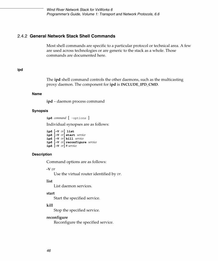
Wind River Network Stack for VxWorks 6Programmer's Guide, Volume 1: Transport and Network Protocols, 6.6
46
2.4.2 General Network Stack Shell Commands
Most shell commands are specific to a particular protocol or technical area. A few are used across technologies or are generic to the stack as a whole. Those commands are documented here.
ipd
The ipd shell command controls the other daemons, such as the multicasting proxy daemon. The component for ipd is INCLUDE_IPD_CMD.
Name
ipd – daemon process command
Synopsis
ipd command [ -options ]
Individual synopses are as follows:
ipd [-V vr] listipd [-V vr] start serviceipd [-V vr] kill serviceipd [-V vr] reconfigure serviceipd [-V vr] # service
Description
Command options are as follows:
-V vrUse the virtual router identified by vr.
listList daemon services.
startStart the specified service.
killStop the specified service.
reconfigureReconfigure the specified service.

2 Configuring and Building the Network Stack2.4 Using Shell Commands
47
2
ipversion
The ipversion shell command displays the product versions. The component for ipversion is INCLUDE_IPVERSION_CMD.
Name
ipversion – show product versions
Synopsis
ipversion
Description
Shows product versions and copyrights for network stack and middleware products.
syslog
The syslog shell command is used to send system log messages. The component for syslog is INCLUDE_IPCOM_SYSLOGD_CMD.
Name
syslog – system log command
Synopsis
syslog echo prio_messagesyslog listsyslog priority facility priosyslog log file [logfile]
Description
Command options are as follows:
prio_message Priority message.
facility prio Priority facility.
logfile The specified log file.
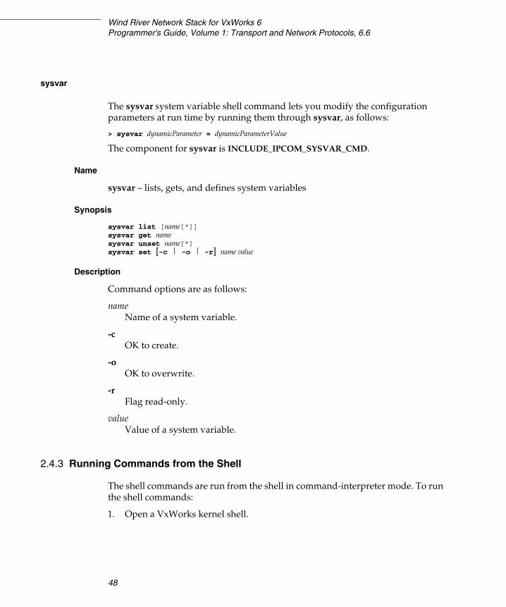
Wind River Network Stack for VxWorks 6Programmer's Guide, Volume 1: Transport and Network Protocols, 6.6
48
sysvar
The sysvar system variable shell command lets you modify the configuration parameters at run time by running them through sysvar, as follows:
> sysvar dynamicParameter = dynamicParameterValue
The component for sysvar is INCLUDE_IPCOM_SYSVAR_CMD.
Name
sysvar – lists, gets, and defines system variables
Synopsis
sysvar list [name[*]]sysvar get namesysvar unset name[*]sysvar set [-c | -o | -r] name value
Description
Command options are as follows:
nameName of a system variable.
-cOK to create.
-oOK to overwrite.
-rFlag read-only.
value Value of a system variable.
2.4.3 Running Commands from the Shell
The shell commands are run from the shell in command-interpreter mode. To run the shell commands:
1. Open a VxWorks kernel shell.
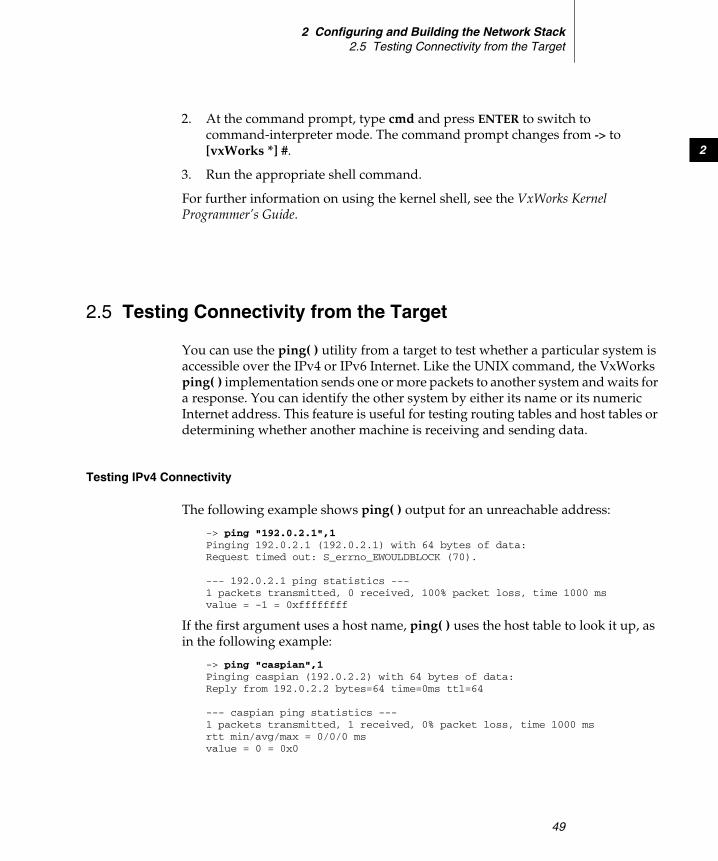
2 Configuring and Building the Network Stack2.5 Testing Connectivity from the Target
49
2
2. At the command prompt, type cmd and press ENTER to switch to command-interpreter mode. The command prompt changes from -> to [vxWorks *] #.
3. Run the appropriate shell command.
For further information on using the kernel shell, see the VxWorks Kernel Programmer’s Guide.
2.5 Testing Connectivity from the Target
You can use the ping( ) utility from a target to test whether a particular system is accessible over the IPv4 or IPv6 Internet. Like the UNIX command, the VxWorks ping( ) implementation sends one or more packets to another system and waits for a response. You can identify the other system by either its name or its numeric Internet address. This feature is useful for testing routing tables and host tables or determining whether another machine is receiving and sending data.
Testing IPv4 Connectivity
The following example shows ping( ) output for an unreachable address:
-> ping "192.0.2.1",1Pinging 192.0.2.1 (192.0.2.1) with 64 bytes of data:Request timed out: S_errno_EWOULDBLOCK (70).
--- 192.0.2.1 ping statistics ---1 packets transmitted, 0 received, 100% packet loss, time 1000 msvalue = -1 = 0xffffffff
If the first argument uses a host name, ping( ) uses the host table to look it up, as in the following example:
-> ping "caspian",1Pinging caspian (192.0.2.2) with 64 bytes of data:Reply from 192.0.2.2 bytes=64 time=0ms ttl=64
--- caspian ping statistics ---1 packets transmitted, 1 received, 0% packet loss, time 1000 msrtt min/avg/max = 0/0/0 msvalue = 0 = 0x0
Wind River Network Stack for VxWorks 6Programmer's Guide, Volume 1: Transport and Network Protocols, 6.6
50
The second argument specifies how many received packets it needs before terminating. A value of 1 tells ping( ) to terminate and report success as soon as the first response packet arrives. A value of 0 tells ping( ) to (send and) receive packets forever or until forcibly terminated). If you specify more than one packet, ping( ) includes summary statistics.
Testing IPv6 Connectivity
The ping6( ) API does not differ much from the ping( ) interface (see the ping6( ) reference entry for the details). Using ping6( ) to test connectivity with a remote site requires tunneling if the local link does not contain a native IPv6 router. For information on how to set up a tunnel that links you to a remote IPv6 router, see the Wind River Network Stack for VxWorks 6 Programmer’s Guide, Volume 3.
51
3Configuring Transport and
Network Protocols
3.1 Introduction 51
3.2 Configuring VxWorks with Transport and Network Layer Support 52
3.1 Introduction
This chapter describes how to configure VxWorks for basic TCP/IP support. Some of the protocols listed in this section are automatically included as part of the core stack, while others can be individually added to a network stack.
The components described in this chapter are:
■ ARP (automatically included)■ ICMP (automatically included)■ ICMPv6 (automatically included)■ IP■ IPv6■ NDP (automatically included)■ TCP■ UDP■ MPLS
Wind River Network Stack for VxWorks 6Programmer's Guide, Volume 1: Transport and Network Protocols, 6.6
52
3.2 Configuring VxWorks with Transport and Network Layer Support
This section explains how to configure VxWorks with the appropriate components to support various networking protocols. For most protocols, two methods of configuration are described:
■ build-time configuration, using either Workbench or vxprj
■ run-time configuration, using the sysvar shell command or other shell command
In some cases, there is a one-to-one mapping between build-time configuration parameters and run-time sysvar parameters. Where such a correspondence exists, you can configure the component either at build time or at run time. In other cases, a build-time configuration component or a sysvar parameter has no counterpart.
For information about using sysvar, see sysvar, p.48.
3.2.1 ARP
ARP is part of the network stack and is automatically included when you build an IPv4 network stack. The only build-time configuration required is to include the arp shell command—see ARP Build-Time Configuration, p.52, for further information.
To modify or display ARP configuration or entries, use the shell command described in ARP Run-Time Configuration, p.53.
For information on configuring Proxy ARP, see 3.2.2 Proxy ARP, p.54.
ARP Build-Time Configuration
ARP uses a shell command and an API for configuration. To build VxWorks with support for this shell command, include the IPCOM arp commands build component, INCLUDE_IPARP_CMD.
! CAUTION: If you exclude a component from the build, Workbench may prompt you to exclude its dependencies. Some dependencies may still be needed by other components in the project. Therefore, accept the dependency exclusions carefully.
3 Configuring Transport and Network Protocols3.2 Configuring VxWorks with Transport and Network Layer Support
53
3
To build VxWorks with support for this API, include the arpLib build component, INCLUDE_ARP_API. This component gives application programs access to the ARP entries so they can list, add, delete ARP entries.
ARP Run-Time Configuration
Use the arp command or the arpLib library routines to configure ARP at run time.
arp
Name
arp – dynamically display and configure ARP and proxy ARP information, or for test purposes
Synopsis
arp [-V routetab] [-i ifname] -aarp [-V routetab] [-i ifname] -Aarp [-V routetab] -d hostaddress arp [-V routetab] [-i ifname] [-p] [-t] -s hostaddress ether_addr
Description
The ARP program displays and modifies the Internet-to-Ethernet address translation tables used by the ARP. With no flags, the program displays the current ARP entry for hostname. The host may be specified by name or by number, using Internet dot notation.
The arp options are as follows:
-i ifname Specify interface. If not specified, the first interface that uses ARP is used.
-t Temporary ARP entry. The entry will time out normally.
-p Public ARP entry (proxy ARP entry). A proxy ARP entry is shown as a route with the proto2 flag set (shown as ‘2’ with route/netstat).
-V routetab Specify route table. 0 if not specified.
The arp commands are as follows:
Wind River Network Stack for VxWorks 6Programmer's Guide, Volume 1: Transport and Network Protocols, 6.6
54
-a
The program displays all of the current ARP entries.
-A Erase all ARP entries on the interface.
-d Delete an entry for the host called hostaddress.
-s hostaddress ether_addr Create an ARP entry for the host having the specified IPv4 and Ethernet address. The Ethernet address is given in the standard format of six hex bytes separated by colons (i.e., 01:02:03:04:05:06). The entry is permanent unless the -t flag is used, but can be removed by using the arp -d command. Public (proxy ARP) entries are added using the -p flag.
arpLib Library
For further information on this library, see the arpLib reference entry.
3.2.2 Proxy ARP
The INCLUDE_IPPROXYARP component supplies configuration parameters to define how proxy ARP will work over the network. Table 3-1 lists the INCLUDE_IPPROXYARP configuration parameters and their default values. Where applicable, a sysvar is also documented for run-time configuration. Modify the values as needed.
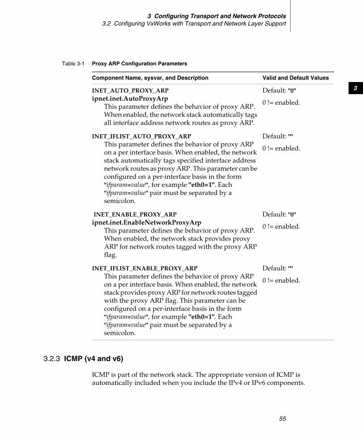
3 Configuring Transport and Network Protocols3.2 Configuring VxWorks with Transport and Network Layer Support
55
3
3.2.3 ICMP (v4 and v6)
ICMP is part of the network stack. The appropriate version of ICMP is automatically included when you include the IPv4 or IPv6 components.
Table 3-1 Proxy ARP Configuration Parameters
Component Name, sysvar, and Description Valid and Default Values
INET_AUTO_PROXY_ARPipnet.inet.AutoProxyArp
This parameter defines the behavior of proxy ARP. When enabled, the network stack automatically tags all interface address network routes as proxy ARP.
Default: "0"
0 != enabled.
INET_IFLIST_AUTO_PROXY_ARPThis parameter defines the behavior of proxy ARP on a per interface basis. When enabled, the network stack automatically tags specified interface address network routes as proxy ARP. This parameter can be configured on a per-interface basis in the form "ifparam=value", for example "eth0=1". Each "ifparam=value" pair must be separated by a semicolon.
Default: ""
0 != enabled.
INET_ENABLE_PROXY_ARPipnet.inet.EnableNetworkProxyArp
This parameter defines the behavior of proxy ARP. When enabled, the network stack provides proxy ARP for network routes tagged with the proxy ARP flag.
Default: "0"
0 != enabled.
INET_IFLIST_ENABLE_PROXY_ARPThis parameter defines the behavior of proxy ARP on a per interface basis. When enabled, the network stack provides proxy ARP for network routes tagged with the proxy ARP flag. This parameter can be configured on a per-interface basis in the form "ifparam=value", for example "eth0=1". Each "ifparam=value" pair must be separated by a semicolon.
Default: ""
0 != enabled.
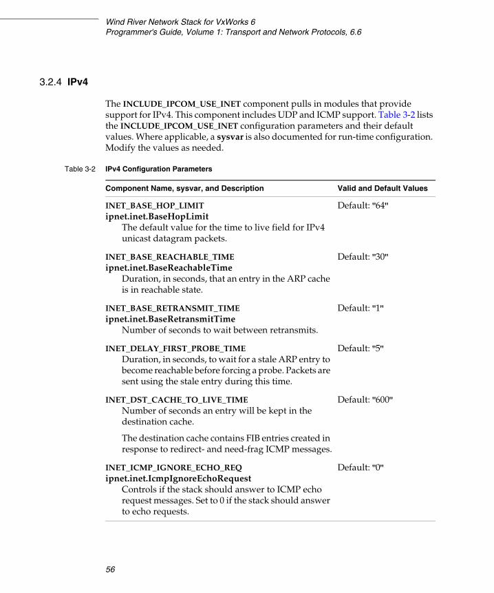
Wind River Network Stack for VxWorks 6Programmer's Guide, Volume 1: Transport and Network Protocols, 6.6
56
3.2.4 IPv4
The INCLUDE_IPCOM_USE_INET component pulls in modules that provide support for IPv4. This component includes UDP and ICMP support. Table 3-2 lists the INCLUDE_IPCOM_USE_INET configuration parameters and their default values. Where applicable, a sysvar is also documented for run-time configuration. Modify the values as needed.
Table 3-2 IPv4 Configuration Parameters
Component Name, sysvar, and Description Valid and Default Values
INET_BASE_HOP_LIMITipnet.inet.BaseHopLimit
The default value for the time to live field for IPv4 unicast datagram packets.
Default: "64"
INET_BASE_REACHABLE_TIMEipnet.inet.BaseReachableTime
Duration, in seconds, that an entry in the ARP cache is in reachable state.
Default: "30"
INET_BASE_RETRANSMIT_TIME ipnet.inet.BaseRetransmitTime
Number of seconds to wait between retransmits.
Default: "1"
INET_DELAY_FIRST_PROBE_TIMEDuration, in seconds, to wait for a stale ARP entry to become reachable before forcing a probe. Packets are sent using the stale entry during this time.
Default: "5"
INET_DST_CACHE_TO_LIVE_TIMENumber of seconds an entry will be kept in the destination cache.
The destination cache contains FIB entries created in response to redirect- and need-frag ICMP messages.
Default: "600"
INET_ICMP_IGNORE_ECHO_REQipnet.inet.IcmpIgnoreEchoRequest
Controls if the stack should answer to ICMP echo request messages. Set to 0 if the stack should answer to echo requests.
Default: "0"

3 Configuring Transport and Network Protocols3.2 Configuring VxWorks with Transport and Network Layer Support
57
3INET_ICMP_IGNORE_TIMESTAMP_REQipnet.inet.IcmpIgnoreTimestampRequest
Controls if the stack should answer to ICMP time stamp request messages. Set to 0 if the stack should answer to timestamp requests.
Default: "0"
INET_ICMP_RATE_LIMIT_BUCKET_SIZEipnet.inet.IcmpRatelimitBucketsize
The number of ICMPv6 messages that the stack is allowed to send in the interval specified by INET_ICMP_RATE_LIMIT_INTERVAL.
For example, if INET_ICMP_RATE_LIMIT_BUCKET_SIZE=10 and INET_ICMP_RATE_LIMIT_INTERVAL=100, then up to 10 ICMP messages can be sent under a 100 msec period. If more messages are sent, they are discarded.
If no ICMP messages are sent for 1000 msec, then the limit is still 10 messages for the next 100 msec period.
Default: "100"
INET_ICMP_RATE_LIMIT_INTERVALipnet.inet.IcmpRatelimitInterval
The Icmp Ratelimit Interval millisecond interval.
Default: "1000"
INET_ICMP_REDIRECT_RECEIVEipnet.inet.IcmpRedirectReceive
Set to != 0 if redirect messages should be accepted and processed.
Default: "1"
Table 3-2 IPv4 Configuration Parameters (cont’d)
Component Name, sysvar, and Description Valid and Default Values

Wind River Network Stack for VxWorks 6Programmer's Guide, Volume 1: Transport and Network Protocols, 6.6
58
INET_ICMP_REDIRECT_SENDipnet.inet.IcmpRedirectSend
Set to 2 if a redirect should be sent and the original message should be forwarded (default).
Set to 1 if a redirect should be sent but the original message should be discarded.
Set to 0 if no redirect should be sent but the original message should be forwarded.
Set to -1 if no redirect should be sent and the original message should be discarded.
Default: "2"
Valid values: "-1", "0", "1", "2"
INET_ICMP_SEND_DST_UNREACHABLEipnet.inet.IcmpSendDestinationUnreachable
Set to != 0 if the stack should send destination unreachable.
Default: "1"
INET_ICMP_SEND_TIME_EXCEEDEDipnet.inet.IcmpSendTimeExceeded
Set to != 0 if the stack should send time exceeded messages.
Default: "1"
INET_MAX_APP_SOLICITipnet.inet.MaxApplicationSolicit
Maximum number of resolve message that is sent to the routing/netlink sockets, if ARP probes failed (or were disabled).
Default: "1"
INET_MAX_MULTICAST_SOLICITipnet.inet.MaxMulticastSolicit
Maximum number of ARP request messages that should be resent before staring to use application probes.
Default: "9"
INET_MAX_PKTS_PENDINGMaximum number of packets that can be waiting for IPv4 to link layer resolution to finish.
Default: "3"
Table 3-2 IPv4 Configuration Parameters (cont’d)
Component Name, sysvar, and Description Valid and Default Values
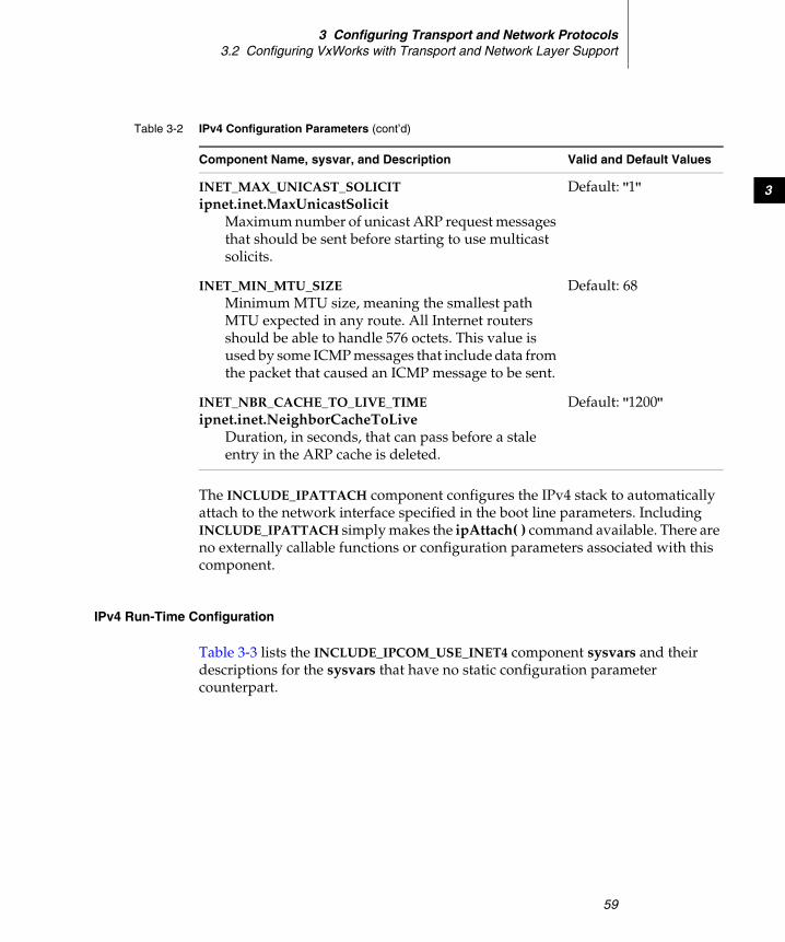
3 Configuring Transport and Network Protocols3.2 Configuring VxWorks with Transport and Network Layer Support
59
3
The INCLUDE_IPATTACH component configures the IPv4 stack to automatically attach to the network interface specified in the boot line parameters. Including INCLUDE_IPATTACH simply makes the ipAttach( ) command available. There are no externally callable functions or configuration parameters associated with this component.
IPv4 Run-Time Configuration
Table 3-3 lists the INCLUDE_IPCOM_USE_INET4 component sysvars and their descriptions for the sysvars that have no static configuration parameter counterpart.
INET_MAX_UNICAST_SOLICITipnet.inet.MaxUnicastSolicit
Maximum number of unicast ARP request messages that should be sent before starting to use multicast solicits.
Default: "1"
INET_MIN_MTU_SIZEMinimum MTU size, meaning the smallest path MTU expected in any route. All Internet routers should be able to handle 576 octets. This value is used by some ICMP messages that include data from the packet that caused an ICMP message to be sent.
Default: 68
INET_NBR_CACHE_TO_LIVE_TIMEipnet.inet.NeighborCacheToLive
Duration, in seconds, that can pass before a stale entry in the ARP cache is deleted.
Default: "1200"
Table 3-2 IPv4 Configuration Parameters (cont’d)
Component Name, sysvar, and Description Valid and Default Values
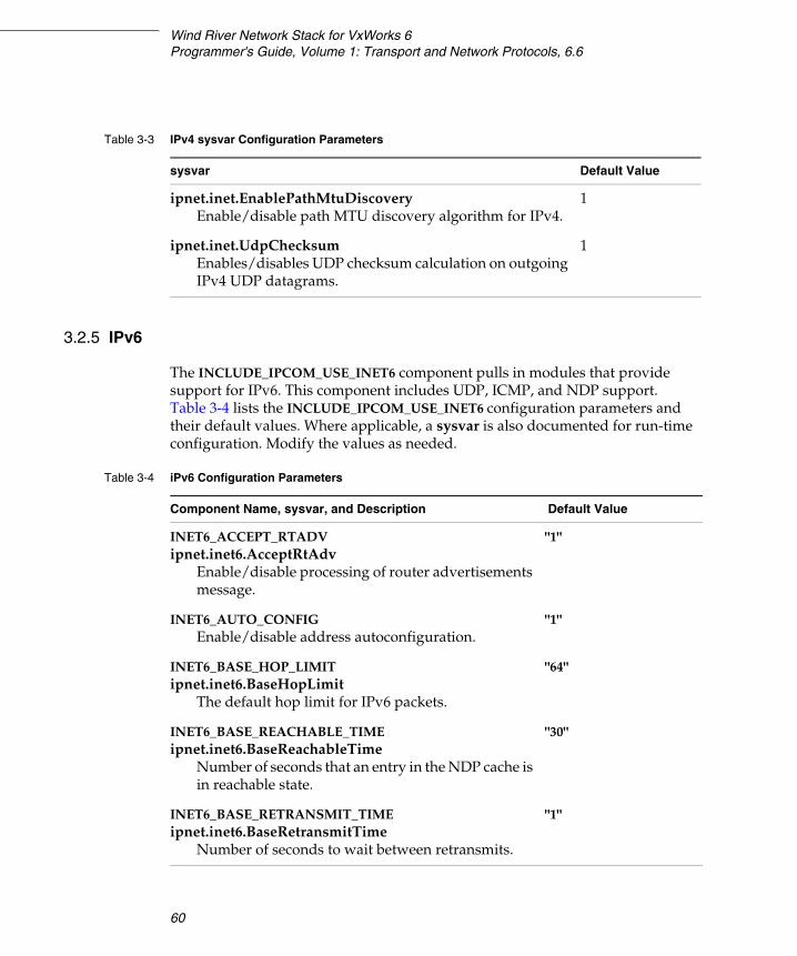
Wind River Network Stack for VxWorks 6Programmer's Guide, Volume 1: Transport and Network Protocols, 6.6
60
3.2.5 IPv6
The INCLUDE_IPCOM_USE_INET6 component pulls in modules that provide support for IPv6. This component includes UDP, ICMP, and NDP support. Table 3-4 lists the INCLUDE_IPCOM_USE_INET6 configuration parameters and their default values. Where applicable, a sysvar is also documented for run-time configuration. Modify the values as needed.
Table 3-3 IPv4 sysvar Configuration Parameters
sysvar Default Value
ipnet.inet.EnablePathMtuDiscoveryEnable/disable path MTU discovery algorithm for IPv4.
1
ipnet.inet.UdpChecksumEnables/disables UDP checksum calculation on outgoing IPv4 UDP datagrams.
1
Table 3-4 iPv6 Configuration Parameters
Component Name, sysvar, and Description Default Value
INET6_ACCEPT_RTADVipnet.inet6.AcceptRtAdv
Enable/disable processing of router advertisements message.
"1"
INET6_AUTO_CONFIGEnable/disable address autoconfiguration.
"1"
INET6_BASE_HOP_LIMITipnet.inet6.BaseHopLimit
The default hop limit for IPv6 packets.
"64"
INET6_BASE_REACHABLE_TIMEipnet.inet6.BaseReachableTime
Number of seconds that an entry in the NDP cache is in reachable state.
"30"
INET6_BASE_RETRANSMIT_TIMEipnet.inet6.BaseRetransmitTime
Number of seconds to wait between retransmits.
"1"
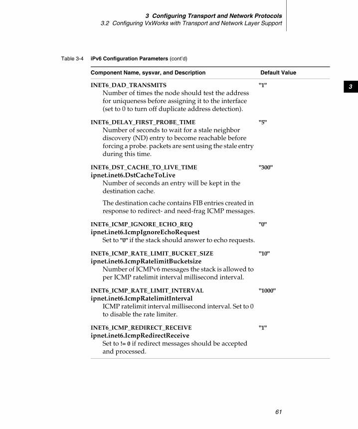
3 Configuring Transport and Network Protocols3.2 Configuring VxWorks with Transport and Network Layer Support
61
3INET6_DAD_TRANSMITSNumber of times the node should test the address for uniqueness before assigning it to the interface (set to 0 to turn off duplicate address detection).
"1"
INET6_DELAY_FIRST_PROBE_TIMENumber of seconds to wait for a stale neighbor discovery (ND) entry to become reachable before forcing a probe. packets are sent using the stale entry during this time.
"5"
INET6_DST_CACHE_TO_LIVE_TIMEipnet.inet6.DstCacheToLive
Number of seconds an entry will be kept in the destination cache.
The destination cache contains FIB entries created in response to redirect- and need-frag ICMP messages.
"300"
INET6_ICMP_IGNORE_ECHO_REQipnet.inet6.IcmpIgnoreEchoRequest
Set to "0" if the stack should answer to echo requests.
"0"
INET6_ICMP_RATE_LIMIT_BUCKET_SIZEipnet.inet6.IcmpRatelimitBucketsize
Number of ICMPv6 messages the stack is allowed to per ICMP ratelimit interval millisecond interval.
"10"
INET6_ICMP_RATE_LIMIT_INTERVALipnet.inet6.IcmpRatelimitInterval
ICMP ratelimit interval millisecond interval. Set to 0 to disable the rate limiter.
"1000"
INET6_ICMP_REDIRECT_RECEIVEipnet.inet6.IcmpRedirectReceive
Set to != 0 if redirect messages should be accepted and processed.
"1"
Table 3-4 iPv6 Configuration Parameters (cont’d)
Component Name, sysvar, and Description Default Value

Wind River Network Stack for VxWorks 6Programmer's Guide, Volume 1: Transport and Network Protocols, 6.6
62
INET6_ICMP_REDIRECT_SENDipnet.inet6.IcmpRedirectSend
Set to 2 if a redirect should be sent and the original message should be forwarded (default).
Set to 1 if a redirect should be sent but the original message should be discarded.
Set to 0 if no redirect should be sent but the original message should be forwarded.
Set to -1 if no redirect should be sent and the original message should be discarded.
"2"
INET6_ICMP_SEND_DST_UNREACHABLEipnet.inet6.IcmpSendDestinationUnreachable
Set to != 0 if the stack should send destination unreachable.
"1"
INET6_ICMP_SEND_TIME_EXCEEDEDipnet.inet6.IcmpSendTimeExceeded
Set to != 0 if the stack should send time exceeded messages.
"1"
INET6_MAX_APP_SOLICITNumber of resolve messages that are sent to routing/netlink sockets if ND probes failed (or are disabled).
"1"
INET6_MAX_MULTICAST_SOLICITNumber of neighbor discovery messages that should be resent before starting to use application solicit. Setting this to a value other than 0 will cause IPv6 ready tests to fail, so exercise caution in changing this parameter.
"0"
INET6_MAX_PKTS_PENDINGNumber of packets that can be waiting for IPv6 to link layer resolution to finish.
"3"
Table 3-4 iPv6 Configuration Parameters (cont’d)
Component Name, sysvar, and Description Default Value
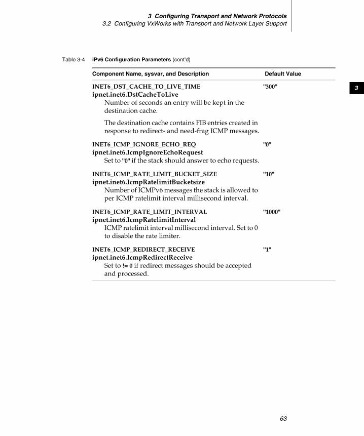
3 Configuring Transport and Network Protocols3.2 Configuring VxWorks with Transport and Network Layer Support
63
3INET6_DST_CACHE_TO_LIVE_TIMEipnet.inet6.DstCacheToLive
Number of seconds an entry will be kept in the destination cache.
The destination cache contains FIB entries created in response to redirect- and need-frag ICMP messages.
"300"
INET6_ICMP_IGNORE_ECHO_REQipnet.inet6.IcmpIgnoreEchoRequest
Set to "0" if the stack should answer to echo requests.
"0"
INET6_ICMP_RATE_LIMIT_BUCKET_SIZEipnet.inet6.IcmpRatelimitBucketsize
Number of ICMPv6 messages the stack is allowed to per ICMP ratelimit interval millisecond interval.
"10"
INET6_ICMP_RATE_LIMIT_INTERVALipnet.inet6.IcmpRatelimitInterval
ICMP ratelimit interval millisecond interval. Set to 0 to disable the rate limiter.
"1000"
INET6_ICMP_REDIRECT_RECEIVEipnet.inet6.IcmpRedirectReceive
Set to != 0 if redirect messages should be accepted and processed.
"1"
Table 3-4 iPv6 Configuration Parameters (cont’d)
Component Name, sysvar, and Description Default Value
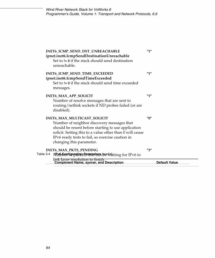
Wind River Network Stack for VxWorks 6Programmer's Guide, Volume 1: Transport and Network Protocols, 6.6
64
INET6_ICMP_SEND_DST_UNREACHABLEipnet.inet6.IcmpSendDestinationUnreachable
Set to != 0 if the stack should send destination unreachable.
"1"
INET6_ICMP_SEND_TIME_EXCEEDEDipnet.inet6.IcmpSendTimeExceeded
Set to != 0 if the stack should send time exceeded messages.
"1"
INET6_MAX_APP_SOLICITNumber of resolve messages that are sent to routing/netlink sockets if ND probes failed (or are disabled).
"1"
INET6_MAX_MULTICAST_SOLICITNumber of neighbor discovery messages that should be resent before starting to use application solicit. Setting this to a value other than 0 will cause IPv6 ready tests to fail, so exercise caution in changing this parameter.
"0"
INET6_MAX_PKTS_PENDINGNumber of packets that can be waiting for IPv6 to link layer resolution to finish.
"3"Table 3-4 iPv6 Configuration Parameters (cont’d)
Component Name, sysvar, and Description Default Value

3 Configuring Transport and Network Protocols3.2 Configuring VxWorks with Transport and Network Layer Support
65
3
The INCLUDE_IP6ATTACH component configures the IPv6 stack to automatically attach to the network interface specified in the boot line parameters. There are no externally callable functions or configuration parameters associated with this component.
It is not necessary to call ip6Attach( ). If IPv6 is enabled, ipAttach( ) binds the driver for both IPv6 and IPv4 services. Both ip6Attach( ) and ipAttach( ) are functionally equivalent.
IPv6 Run-Time Configuration
Table 3-5 lists the INCLUDE_IPCOM_USE_INET6 component sysvars and their descriptions for the sysvar commands that have no static configuration parameter counterpart.
INET6_NBR_CACHE_TO_LIVE_TIMEipnet.inet6.NeighborCacheToLive
Number of seconds that can pass before a stale entry in the neighbor cache is deleted.
"1200"
INET6_ROUTER_LIFETIMENumber of seconds this router can be used as gateway after a router advertisement had been sent; only used when the network stack is configured as a router.
"1800"
Table 3-4 iPv6 Configuration Parameters (cont’d)
Component Name, sysvar, and Description Default Value
Table 3-5 IPv6 sysvar Configuration Parameters
sysvar Default Value
ipnet.inet6.RouterLifetimeNumber of seconds this router can be used as gateway after a router advertisement had been sent, only used when configured as a router
1800
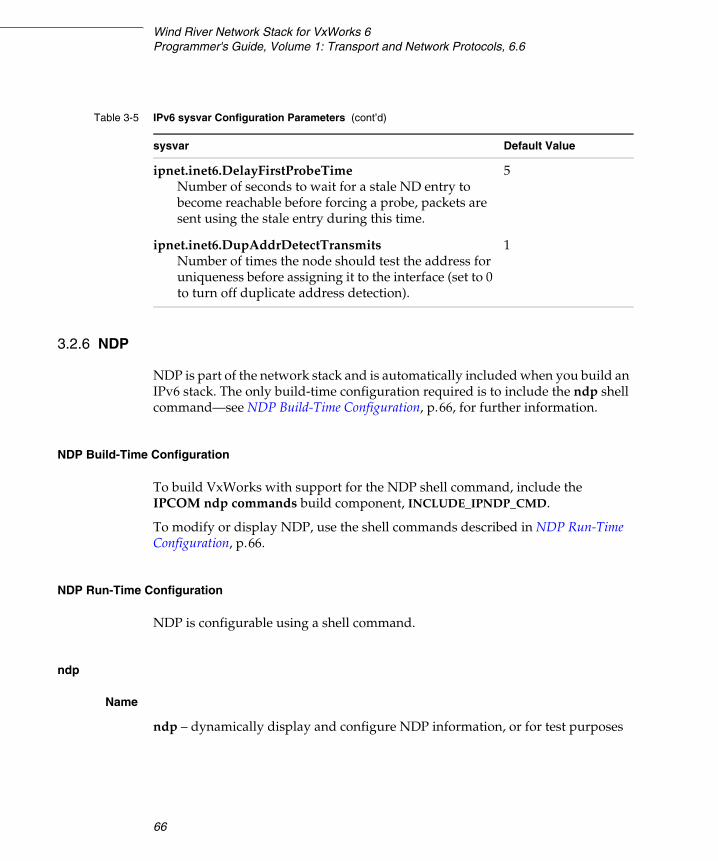
Wind River Network Stack for VxWorks 6Programmer's Guide, Volume 1: Transport and Network Protocols, 6.6
66
3.2.6 NDP
NDP is part of the network stack and is automatically included when you build an IPv6 stack. The only build-time configuration required is to include the ndp shell command—see NDP Build-Time Configuration, p.66, for further information.
NDP Build-Time Configuration
To build VxWorks with support for the NDP shell command, include the IPCOM ndp commands build component, INCLUDE_IPNDP_CMD.
To modify or display NDP, use the shell commands described in NDP Run-Time Configuration, p.66.
NDP Run-Time Configuration
NDP is configurable using a shell command.
ndp
Name
ndp – dynamically display and configure NDP information, or for test purposes
ipnet.inet6.DelayFirstProbeTimeNumber of seconds to wait for a stale ND entry to become reachable before forcing a probe, packets are sent using the stale entry during this time.
5
ipnet.inet6.DupAddrDetectTransmitsNumber of times the node should test the address for uniqueness before assigning it to the interface (set to 0 to turn off duplicate address detection).
1
Table 3-5 IPv6 sysvar Configuration Parameters (cont’d)
sysvar Default Value
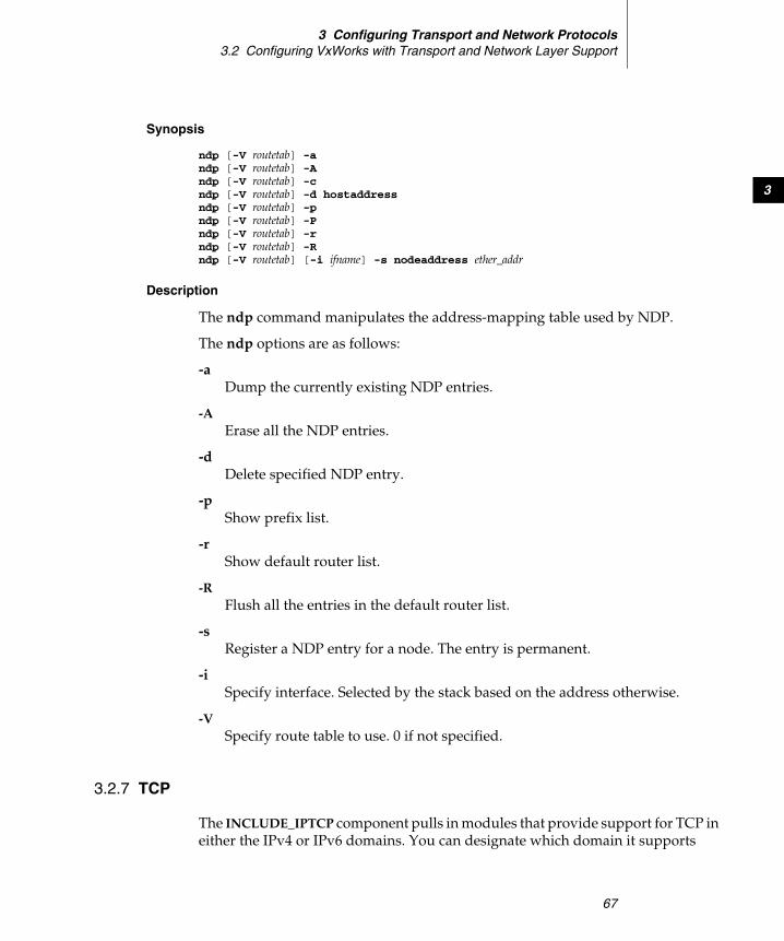
3 Configuring Transport and Network Protocols3.2 Configuring VxWorks with Transport and Network Layer Support
67
3
Synopsis
ndp [-V routetab] -andp [-V routetab] -Andp [-V routetab] -cndp [-V routetab] -d hostaddressndp [-V routetab] -pndp [-V routetab] -Pndp [-V routetab] -rndp [-V routetab] -Rndp [-V routetab] [-i ifname] -s nodeaddress ether_addr
Description
The ndp command manipulates the address-mapping table used by NDP.
The ndp options are as follows:
-a Dump the currently existing NDP entries.
-AErase all the NDP entries.
-d Delete specified NDP entry.
-p Show prefix list.
-r Show default router list.
-R Flush all the entries in the default router list.
-s Register a NDP entry for a node. The entry is permanent.
-i Specify interface. Selected by the stack based on the address otherwise.
-V Specify route table to use. 0 if not specified.
3.2.7 TCP
The INCLUDE_IPTCP component pulls in modules that provide support for TCP in either the IPv4 or IPv6 domains. You can designate which domain it supports

Wind River Network Stack for VxWorks 6Programmer's Guide, Volume 1: Transport and Network Protocols, 6.6
68
when you build the Platform source (see 3.2 Configuring VxWorks with Transport and Network Layer Support, p.52). Table 3-6 lists the INCLUDE_IPTCP configuration parameters and their default values. Modify these values as needed.
Table 3-6 TCP Configuration Parameters
Component Name and Description Valid and Default Values
TCP_CONN_TIMEOUTThe connection timeout, or number of seconds stack will attempt to create a TCP connection before giving up.
Default: 30
TCP_MAX_MSSDefines the largest maximum segment size (MSS) that TCP will ever suggest. The actual MSS suggested might be smaller than this number if it depends on the MTU for the interface.
Default: 0
A value of 0 specifies the largest MSS allowed by the MTU.
TCP_MAX_RETRANSMITSMaximum number of times a TCP segment is resent before giving up and sending an IPTCP_ERRNO_ETIMEDOUT error. Exponential back off is applied before each resend (max time between two resends is 1 minute).
Default: 10
TCP_MSLTCP sockets that enter the TIME_WAIT state remain in that state for 2 times this value. Should be 120 seconds (2 minutes) according to RFC 793, but most TCP/IP stacks set this value to 30 seconds.
Default: 30
TCP_SEGMENT_MULTIPLIERSegment size multiplier used on outgoing segments when the outgoing interface supports TCP segmentation offload.
Default: 2
Generally, the higher the value, the better the performance; however, factors higher than 2 are not guaranteed to work on all network cars.
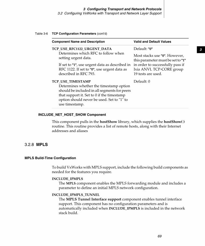
3 Configuring Transport and Network Protocols3.2 Configuring VxWorks with Transport and Network Layer Support
69
3
INCLUDE_NET_HOST_SHOW Component
This component pulls in the hostShow library, which supplies the hostShow( ) routine. This routine provides a list of remote hosts, along with their Internet addresses and aliases
3.2.8 MPLS
MPLS Build-Time Configuration
To build VxWorks with MPLS support, include the following build components as needed for the features you require.
INCLUDE_IPMPLSThe MPLS component enables the MPLS forwarding module and includes a parameter to define an initial MPLS network configuration.
INCLUDE_IPMPLS_TUNNELThe MPLS Tunnel Interface support component enables tunnel interface support. This component has no configuration parameters and is automatically included when INCLUDE_IPMPLS is included in the network stack build.
TCP_USE_RFC1122_URGENT_DATADetermines which RFC to follow when setting urgent data.
If set to "1", use urgent data as described in RFC 1122. If set to "0", use urgent data as described in RFC 793.
Default: "0"
Most stacks use "0". However, this parameter must be set to "1" in order to successfully pass if Ixia ANVL TCP-CORE group 19 tests are used.
TCP_USE_TIMESTAMPDetermines whether the timestamp option should be included in all segments for peers that support it. Set to 0 if the timestamp option should never be used. Set to "1" to use timestamp.
Default: 0
Table 3-6 TCP Configuration Parameters (cont’d)
Component Name and Description Valid and Default Values
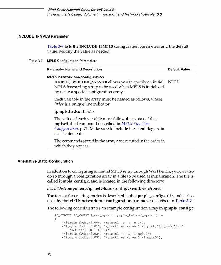
Wind River Network Stack for VxWorks 6Programmer's Guide, Volume 1: Transport and Network Protocols, 6.6
70
INCLUDE_IPMPLS Parameter
Table 3-7 lists the INCLUDE_IPMPLS configuration parameters and the default value. Modify the value as needed.
Alternative Static Configuration
In addition to configuring an initial MPLS setup through Workbench, you can also do so through a configuration array in a file to be used at initialization. The file is called ipmpls_config.c, and is located in the following directory:
installDir/components/ip_net2-6.x/osconfig/vxworks/src/ipnet
The format for creating entries is described in the ipmpls_config.c file, and is also used by the MPLS network pre-configuration parameter described in Table 3-7.
The following code illustrates an example configuration array in ipmpls_config.c:
IP_STATIC IP_CONST Ipcom_sysvar ipmpls_fwdconf_sysvar[] ={
{"ipmpls.fwdconf.00", "mplsctl -s -a -n 1"},{"ipmpls.fwdconf.01", "mplsctl -s -a -n 1 -o push,123,push,234,”
“set,eth0,10.1.1.239"},{"ipmpls.fwdconf.02", "mplsctl -s -a -I mpls0"},{"ipmpls.fwdconf.03", "mplsctl -s -b -n 1 -I mpls0"},
Table 3-7 MPLS Configuration Parameters
Parameter Name and Description Default Value
MPLS network pre-configurationIPMPLS_FWDCONF_SYSVAR allows you to specify an initial MPLS forwarding setup to be used when MPLS is initialized by using a special configuration array.
Each variable in the array must be named as follows, where index is a unique line indicator:
ipmpls.fwdconf.index
The value of each variable must follow the syntax of the mplsctl shell command described in MPLS Run-Time Configuration, p.71. Make sure to include the silent flag, -s, in each statement.
The commands stored in the array are executed in the order in which they appear.
NULL
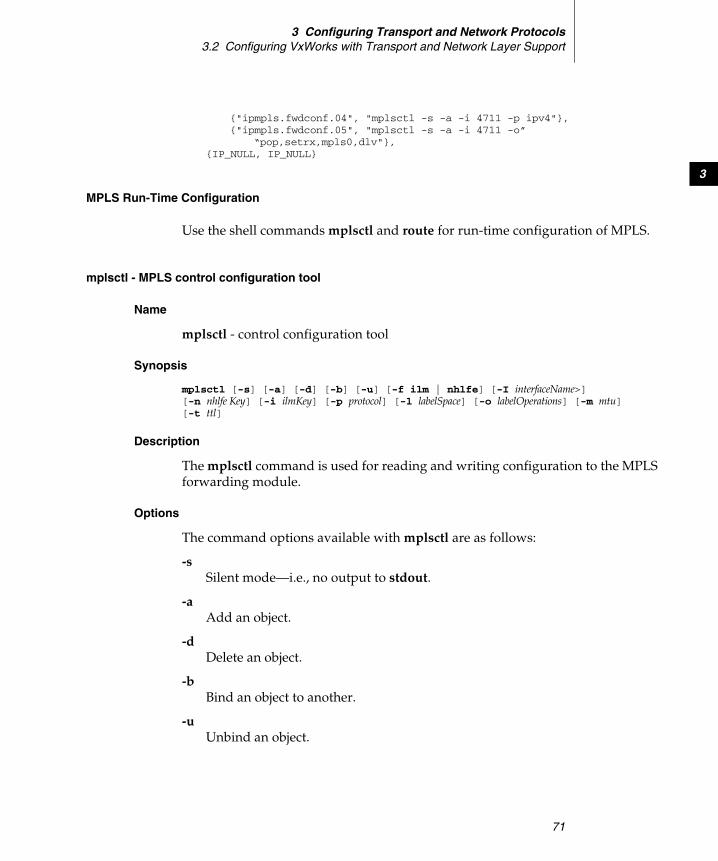
3 Configuring Transport and Network Protocols3.2 Configuring VxWorks with Transport and Network Layer Support
71
3
{"ipmpls.fwdconf.04", "mplsctl -s -a -i 4711 -p ipv4"},{"ipmpls.fwdconf.05", "mplsctl -s -a -i 4711 -o”
“pop,setrx,mpls0,dlv"},{IP_NULL, IP_NULL}
MPLS Run-Time Configuration
Use the shell commands mplsctl and route for run-time configuration of MPLS.
mplsctl - MPLS control configuration tool
Name
mplsctl - control configuration tool
Synopsis
mplsctl [-s] [-a] [-d] [-b] [-u] [-f ilm | nhlfe] [-I interfaceName>] [-n nhlfe Key] [-i ilmKey] [-p protocol] [-l labelSpace] [-o labelOperations] [-m mtu] [-t ttl]
Description
The mplsctl command is used for reading and writing configuration to the MPLS forwarding module.
Options
The command options available with mplsctl are as follows:
-sSilent mode—i.e., no output to stdout.
-aAdd an object.
-dDelete an object.
-bBind an object to another.
-uUnbind an object.
Wind River Network Stack for VxWorks 6Programmer's Guide, Volume 1: Transport and Network Protocols, 6.6
72
-fFlush the incoming label map (ILM) or Next-Hop Label Forwarding Entry (NHLFE) table.
Object Options
The object options available with mplsctl are as follows:
-I interfaceNameUsed together with tunnels and label spaces.
-n nhlfeKeyUsed with NHLFE, tunnels, and cross-connects.
-i ilmKeyUsed with ILMs and cross-connects.
-p protocolEither IPv4 or IPv6.
-m mtuUsed with tunnels and NHLFE.
-tSet MPLS time to live (TTL) to the value specified in the payload IP header (default 255). Used with NHLFEs.
-o labelOperationsA comma-separated list of label operations used with NHLFEs and ILMs. See NHLFE Label Operations, p.72, and ILM Label Operations, p.73, for label operations.
NHLFE Label Operations
The valid label operations for use with NHLFE are as follows:
push,labelPush a label.
fwd,keyForward the packet using the NHLFE identified by the key.
set,ifname,addressSet the outgoing interface and next hop address. Valid address formats are: IPv4, IPv6.
3 Configuring Transport and Network Protocols3.2 Configuring VxWorks with Transport and Network Layer Support
73
3
ILM Label Operations
The valid label operations for use with ILM are as follows:
pop
Pop a label.
peek Look at the label on top of the label stack and perform the operations associated with it.
dlv Deliver packet to the IPv4/IPv6 stack.
push,labelPush a label.
fwd,keyForward the packet using the NHLFE identified by the key.
set,destinationSet destination address to route to. Valid formats: IPv4, IPv6.
setrx,ifnameSet receiving interface. Cannot be used together with the vr operation.
vr,indexSet IPv4/IPv6 route table to use when doing forwarding. Cannot be used together with the setrx operation.
Examples
To add an IPv4 ILM with label 4711 in labelspace 17:
mplsctl -a -i 4711:17 -p ipv4
To add operations on an ILM:
mplsctl -a -i 4711:17 -o pop,setrx,eth0,dlv
To add an NHLFE with auto generated key:
mplsctl -a -n 0
To add an NHLFE with a user defined key (1234):
mplsctl -a -n 1234
To add operations on an NHLFE:
mplsctl -a -n 1234 -o push,2345,set,eth0,10.1.1.1
Wind River Network Stack for VxWorks 6Programmer's Guide, Volume 1: Transport and Network Protocols, 6.6
74
To add a cross-connect (ILM to NHLFE):
mplsctl -b -i 4711:17 -n 1234
To setup ILM operations to deliver to the network stack with virtual router #2 specified:
mplsctl -a -i 4711:17 -o pop,vr,2,dlv
To setup ILM operations to deliver to network stack for further forwarding with a special destination address (192.168.0.17)specified:
mplsctl -a -i 4711:17 -o pop,set,192.168.0.17,dlv
To create an MPLS tunnel interface named mpls0:
mplsctl -a -I mpls0
To bind the MPLS tunnel interface mpls0 to NHLFE with key 1234.
mplsctl -b -I mpls0 -n 1234
route - MPLS-specific commands
This section describes only the MPLS options for the route shell command. The route shell command is fully described in 4.6 Adjusting the Route Table, p.96.
Name
route - a utility to manually manipulate network routing
Synopsis
route [-n] command [[modifiers] args]
Description
The route shell command contains a specific option for managing MPLS shortcut routes.
Options
There is one MPLS-specific option you can use with the route command:
-mpls nhlfeKey
This option manages a shortcut route that corresponds to the NHLFE identified by the key.
3 Configuring Transport and Network Protocols3.2 Configuring VxWorks with Transport and Network Layer Support
75
3
Examples
To add a shortcut for the network (FEC) 1.2.3.0/24 and map it to the NHLFE identified by key 17:
route inet add -mpls 17 network netmask 255.255.255.0 1.2.3.0
To delete a shortcut for the network (FEC) 1.2.3.0/24 that is mapped to the NHLFE identified by key 17:
route inet delete -mpls 17 network netmask 255.255.255.0 1.2.3.0

Wind River Network Stack for VxWorks 6Programmer's Guide, Volume 1: Transport and Network Protocols, 6.6
76
77
4Adding Routing Support
4.1 Introduction 77
4.2 Building and Configuring RIP and RIPng 79
4.3 Policy-Based Routing 90
4.4 VRRP 93
4.5 Fast Path 95
4.6 Adjusting the Route Table 96
4.1 Introduction
This chapter describes the route storage mechanism and the protocols used to maintain the contents of the route table.
Implementation
The route table implementation is included in IPCOM, the network stack and the middleware common library.
The IPCOM route implementation has the following features and characteristics:
■ Handles an unlimited number of route tables.
■ The key length can be different for each route table.
Wind River Network Stack for VxWorks 6Programmer's Guide, Volume 1: Transport and Network Protocols 6.6
78
■ Supports noncontinuous masks. The most specific match is defined as the entry that matches the most of the nonmasked bits starting with the most significant bit.
■ No code locking for maximum performance. External synchronization must be provided by the (very few) applications that need to use a single route table from multiple threads of execution.
■ Lookups are done in O(log(N)) time in the best, average and worst case, where N is the number of route entries in the table. Finding a specific entry in a table with one million entries is only ten times as slow as finding it in a table with one thousand entries.
■ No global data is used; different route tables can be used from different threads of execution without synchronization.
■ Applications may get notified when a route changes.
Storage Mechanism
The route table functions are based on a PATRICIA1 tree. A PATRICIA tree has the following characteristics:
■ All data is stored at leaves.
■ Inner nodes of the tree just contain links.
■ The form of the tree only depends on the keys of the elements, not the order of insertion.
■ Branches of the tree are as long as it takes to make a difference between keys.
Searching in a PATRICIA tree starts from the root node and from the most significant bit in the search key. Each internal node contains a bit number (that will increase when walking down the tree), and the next node is selected based on whenever this bit is set or cleared in the search key. The search is stopped when reaching a leaf node.
If the leaf node is not a perfect match, the algorithm backtracks up the tree looking for indications that a more general mask may apply (i.e., one having fewer one bits). The backtracking continues until an entry is found which matches when using the mask or until it is clear that nothing will match.
If none of these route table storage mechanisms is appropriate to your needs, you may implement your own, using the PATRICIA tree implementation as a model.
1. Donald R. Morrison, PATRICIA - Practical Algorithm to Retrieve Information Coded in Alphanumeric, Journal of the ACM, 15(4):514-534, October 1968
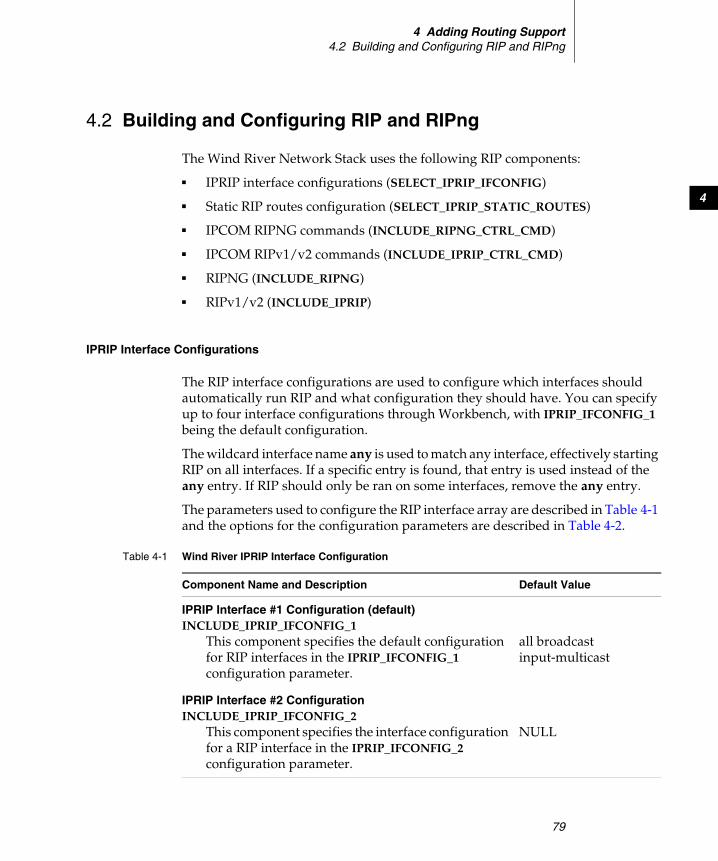
4 Adding Routing Support4.2 Building and Configuring RIP and RIPng
79
4
4.2 Building and Configuring RIP and RIPng
The Wind River Network Stack uses the following RIP components:
■ IPRIP interface configurations (SELECT_IPRIP_IFCONFIG)
■ Static RIP routes configuration (SELECT_IPRIP_STATIC_ROUTES)
■ IPCOM RIPNG commands (INCLUDE_RIPNG_CTRL_CMD)
■ IPCOM RIPv1/v2 commands (INCLUDE_IPRIP_CTRL_CMD)
■ RIPNG (INCLUDE_RIPNG)
■ RIPv1/v2 (INCLUDE_IPRIP)
IPRIP Interface Configurations
The RIP interface configurations are used to configure which interfaces should automatically run RIP and what configuration they should have. You can specify up to four interface configurations through Workbench, with IPRIP_IFCONFIG_1 being the default configuration.
The wildcard interface name any is used to match any interface, effectively starting RIP on all interfaces. If a specific entry is found, that entry is used instead of the any entry. If RIP should only be ran on some interfaces, remove the any entry.
The parameters used to configure the RIP interface array are described in Table 4-1 and the options for the configuration parameters are described in Table 4-2.
Table 4-1 Wind River IPRIP Interface Configuration
Component Name and Description Default Value
IPRIP Interface #1 Configuration (default)INCLUDE_IPRIP_IFCONFIG_1
This component specifies the default configuration for RIP interfaces in the IPRIP_IFCONFIG_1 configuration parameter.
all broadcast input-multicast
IPRIP Interface #2 ConfigurationINCLUDE_IPRIP_IFCONFIG_2
This component specifies the interface configuration for a RIP interface in the IPRIP_IFCONFIG_2 configuration parameter.
NULL
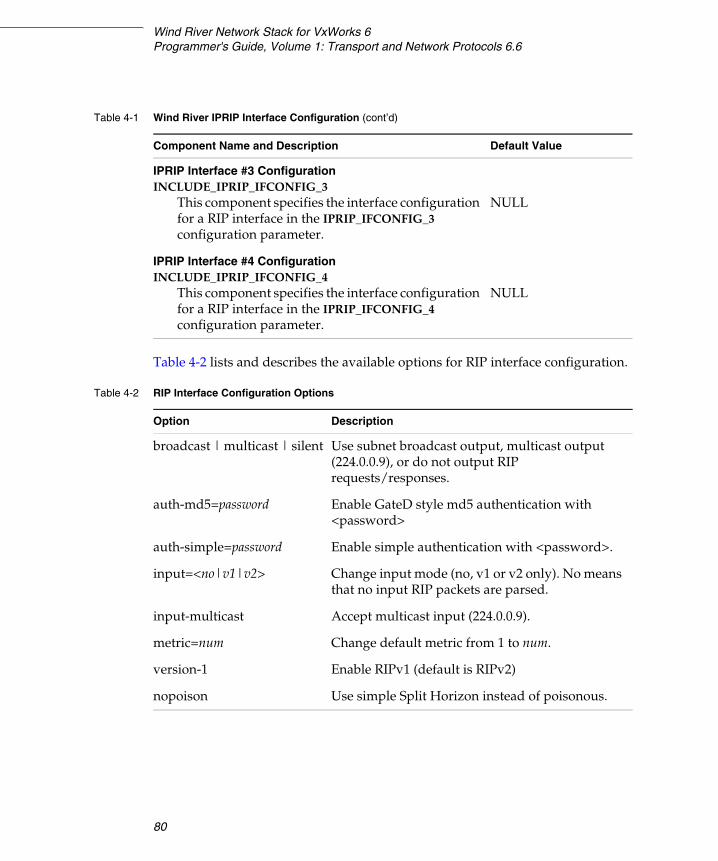
Wind River Network Stack for VxWorks 6Programmer's Guide, Volume 1: Transport and Network Protocols 6.6
80
Table 4-2 lists and describes the available options for RIP interface configuration.
IPRIP Interface #3 ConfigurationINCLUDE_IPRIP_IFCONFIG_3
This component specifies the interface configuration for a RIP interface in the IPRIP_IFCONFIG_3 configuration parameter.
NULL
IPRIP Interface #4 ConfigurationINCLUDE_IPRIP_IFCONFIG_4
This component specifies the interface configuration for a RIP interface in the IPRIP_IFCONFIG_4 configuration parameter.
NULL
Table 4-1 Wind River IPRIP Interface Configuration (cont’d)
Component Name and Description Default Value
Table 4-2 RIP Interface Configuration Options
Option Description
broadcast | multicast | silent Use subnet broadcast output, multicast output (224.0.0.9), or do not output RIP requests/responses.
auth-md5=password Enable GateD style md5 authentication with <password>
auth-simple=password Enable simple authentication with <password>.
input=<no|v1|v2> Change input mode (no, v1 or v2 only). No means that no input RIP packets are parsed.
input-multicast Accept multicast input (224.0.0.9).
metric=num Change default metric from 1 to num.
version-1 Enable RIPv1 (default is RIPv2)
nopoison Use simple Split Horizon instead of poisonous.
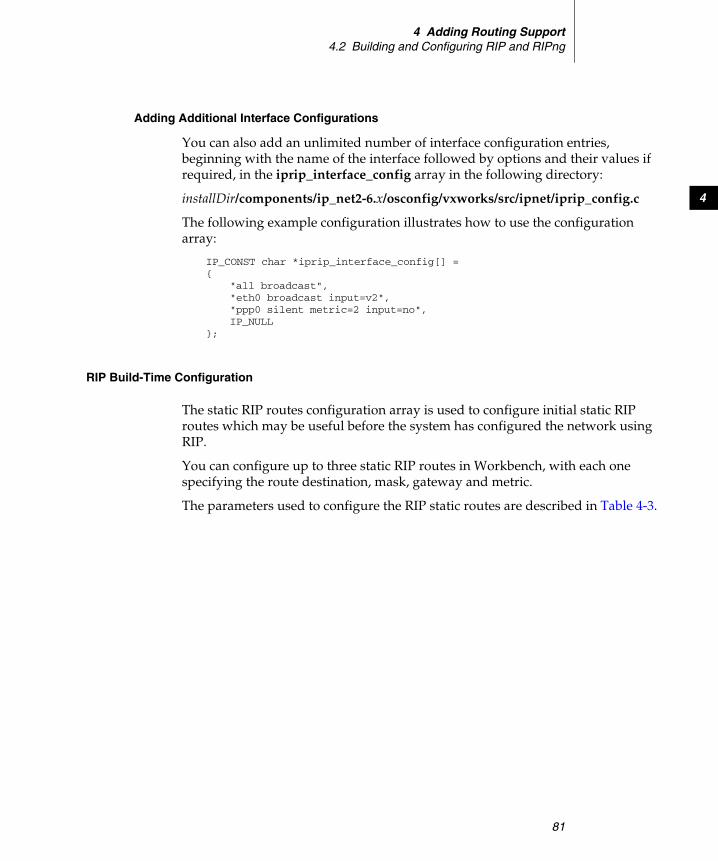
4 Adding Routing Support4.2 Building and Configuring RIP and RIPng
81
4
Adding Additional Interface Configurations
You can also add an unlimited number of interface configuration entries, beginning with the name of the interface followed by options and their values if required, in the iprip_interface_config array in the following directory:
installDir/components/ip_net2-6.x/osconfig/vxworks/src/ipnet/iprip_config.c
The following example configuration illustrates how to use the configuration array:
IP_CONST char *iprip_interface_config[] ={
"all broadcast","eth0 broadcast input=v2","ppp0 silent metric=2 input=no",IP_NULL
};
RIP Build-Time Configuration
The static RIP routes configuration array is used to configure initial static RIP routes which may be useful before the system has configured the network using RIP.
You can configure up to three static RIP routes in Workbench, with each one specifying the route destination, mask, gateway and metric.
The parameters used to configure the RIP static routes are described in Table 4-3.
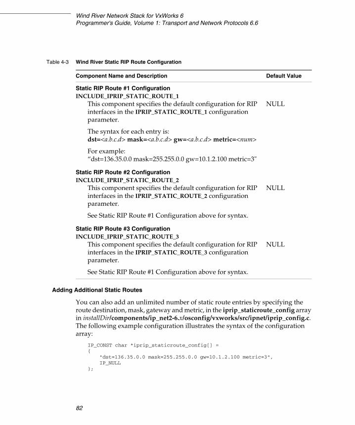
Wind River Network Stack for VxWorks 6Programmer's Guide, Volume 1: Transport and Network Protocols 6.6
82
Adding Additional Static Routes
You can also add an unlimited number of static route entries by specifying the route destination, mask, gateway and metric, in the iprip_staticroute_config array in installDir/components/ip_net2-6.x/osconfig/vxworks/src/ipnet/iprip_config.c. The following example configuration illustrates the syntax of the configuration array:
IP_CONST char *iprip_staticroute_config[] ={
"dst=136.35.0.0 mask=255.255.0.0 gw=10.1.2.100 metric=3",IP_NULL
};
Table 4-3 Wind River Static RIP Route Configuration
Component Name and Description Default Value
Static RIP Route #1 ConfigurationINCLUDE_IPRIP_STATIC_ROUTE_1
This component specifies the default configuration for RIP interfaces in the IPRIP_STATIC_ROUTE_1 configuration parameter.
The syntax for each entry is: dst=<a.b.c.d> mask=<a.b.c.d> gw=<a.b.c.d> metric=<num>
For example:“dst=136.35.0.0 mask=255.255.0.0 gw=10.1.2.100 metric=3"
NULL
Static RIP Route #2 ConfigurationINCLUDE_IPRIP_STATIC_ROUTE_2
This component specifies the default configuration for RIP interfaces in the IPRIP_STATIC_ROUTE_2 configuration parameter.
See Static RIP Route #1 Configuration above for syntax.
NULL
Static RIP Route #3 ConfigurationINCLUDE_IPRIP_STATIC_ROUTE_3
This component specifies the default configuration for RIP interfaces in the IPRIP_STATIC_ROUTE_3 configuration parameter.
See Static RIP Route #1 Configuration above for syntax.
NULL
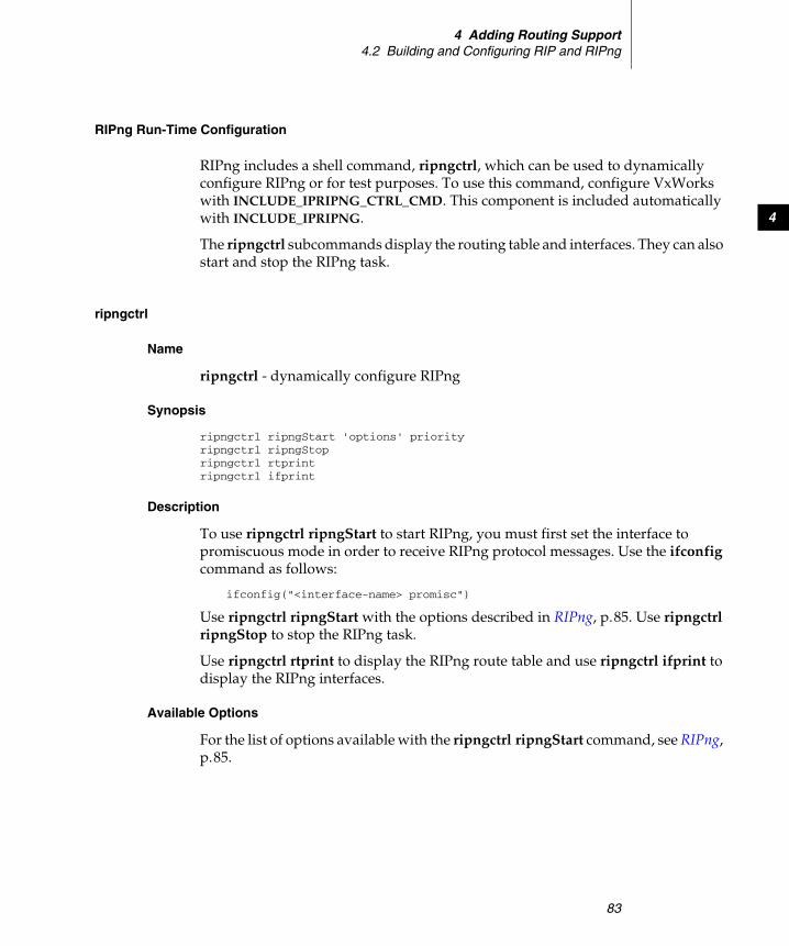
4 Adding Routing Support4.2 Building and Configuring RIP and RIPng
83
4
RIPng Run-Time Configuration
RIPng includes a shell command, ripngctrl, which can be used to dynamically configure RIPng or for test purposes. To use this command, configure VxWorks with INCLUDE_IPRIPNG_CTRL_CMD. This component is included automatically with INCLUDE_IPRIPNG.
The ripngctrl subcommands display the routing table and interfaces. They can also start and stop the RIPng task.
ripngctrl
Name
ripngctrl - dynamically configure RIPng
Synopsis
ripngctrl ripngStart 'options' priorityripngctrl ripngStopripngctrl rtprintripngctrl ifprint
Description
To use ripngctrl ripngStart to start RIPng, you must first set the interface to promiscuous mode in order to receive RIPng protocol messages. Use the ifconfig command as follows:
ifconfig("<interface-name> promisc")
Use ripngctrl ripngStart with the options described in RIPng, p.85. Use ripngctrl ripngStop to stop the RIPng task.
Use ripngctrl rtprint to display the RIPng route table and use ripngctrl ifprint to display the RIPng interfaces.
Available Options
For the list of options available with the ripngctrl ripngStart command, see RIPng, p.85.
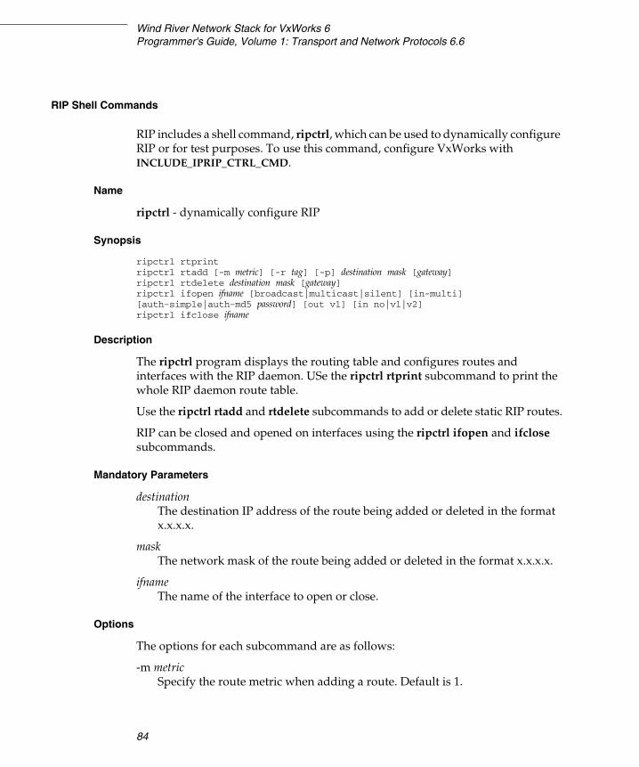
Wind River Network Stack for VxWorks 6Programmer's Guide, Volume 1: Transport and Network Protocols 6.6
84
RIP Shell Commands
RIP includes a shell command, ripctrl, which can be used to dynamically configure RIP or for test purposes. To use this command, configure VxWorks with INCLUDE_IPRIP_CTRL_CMD.
Name
ripctrl - dynamically configure RIP
Synopsis
ripctrl rtprintripctrl rtadd [-m metric] [-r tag] [-p] destination mask [gateway]ripctrl rtdelete destination mask [gateway]ripctrl ifopen ifname [broadcast|multicast|silent] [in-multi] [auth-simple|auth-md5 password] [out v1] [in no|v1|v2]ripctrl ifclose ifname
Description
The ripctrl program displays the routing table and configures routes and interfaces with the RIP daemon. USe the ripctrl rtprint subcommand to print the whole RIP daemon route table.
Use the ripctrl rtadd and rtdelete subcommands to add or delete static RIP routes.
RIP can be closed and opened on interfaces using the ripctrl ifopen and ifclose subcommands.
Mandatory Parameters
destinationThe destination IP address of the route being added or deleted in the format x.x.x.x.
maskThe network mask of the route being added or deleted in the format x.x.x.x.
ifnameThe name of the interface to open or close.
Options
The options for each subcommand are as follows:
-m metricSpecify the route metric when adding a route. Default is 1.
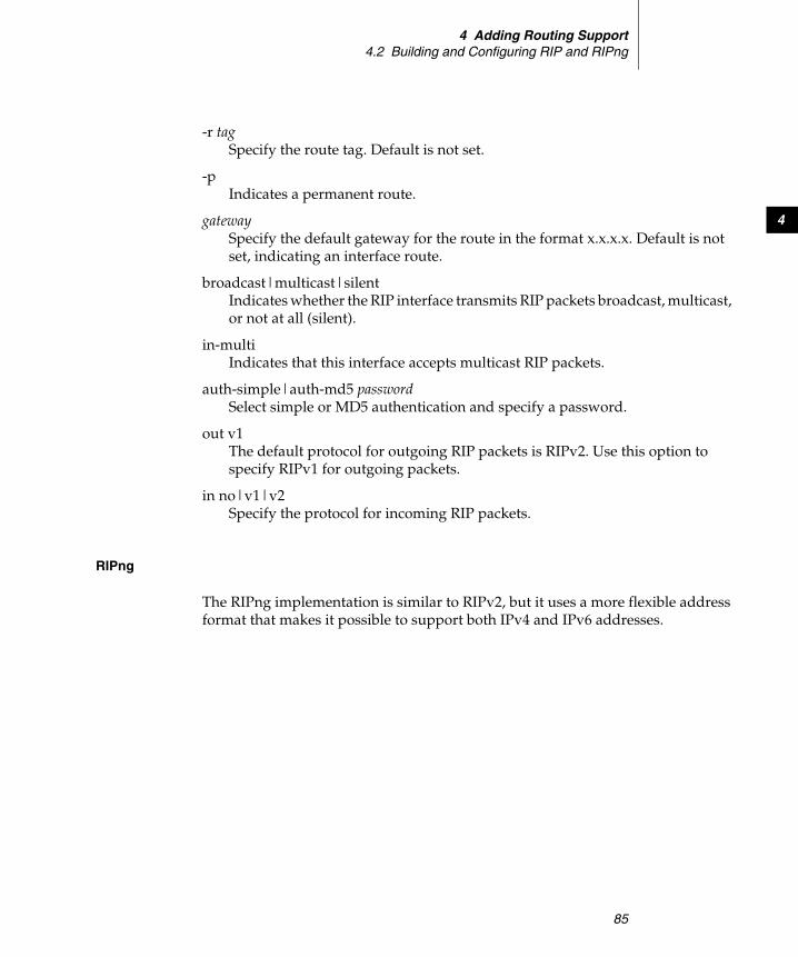
4 Adding Routing Support4.2 Building and Configuring RIP and RIPng
85
4
-r tagSpecify the route tag. Default is not set.
-pIndicates a permanent route.
gatewaySpecify the default gateway for the route in the format x.x.x.x. Default is not set, indicating an interface route.
broadcast|multicast|silentIndicates whether the RIP interface transmits RIP packets broadcast, multicast, or not at all (silent).
in-multiIndicates that this interface accepts multicast RIP packets.
auth-simple|auth-md5 passwordSelect simple or MD5 authentication and specify a password.
out v1The default protocol for outgoing RIP packets is RIPv2. Use this option to specify RIPv1 for outgoing packets.
in no|v1|v2Specify the protocol for incoming RIP packets.
RIPng
The RIPng implementation is similar to RIPv2, but it uses a more flexible address format that makes it possible to support both IPv4 and IPv6 addresses.
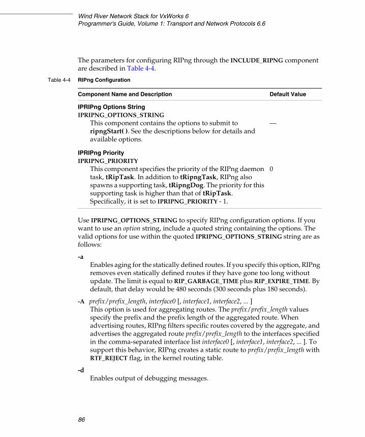
Wind River Network Stack for VxWorks 6Programmer's Guide, Volume 1: Transport and Network Protocols 6.6
86
The parameters for configuring RIPng through the INCLUDE_RIPNG component are described in Table 4-4.
Use IPRIPNG_OPTIONS_STRING to specify RIPng configuration options. If you want to use an option string, include a quoted string containing the options. The valid options for use within the quoted IPRIPNG_OPTIONS_STRING string are as follows:
-aEnables aging for the statically defined routes. If you specify this option, RIPng removes even statically defined routes if they have gone too long without update. The limit is equal to RIP_GARBAGE_TIME plus RIP_EXPIRE_TIME. By default, that delay would be 480 seconds (300 seconds plus 180 seconds).
-A prefix/prefix_length, interface0 [, interface1, interface2, ... ]This option is used for aggregating routes. The prefix/prefix_length values specify the prefix and the prefix length of the aggregated route. When advertising routes, RIPng filters specific routes covered by the aggregate, and advertises the aggregated route prefix/prefix_length to the interfaces specified in the comma-separated interface list interface0 [, interface1, interface2, ... ]. To support this behavior, RIPng creates a static route to prefix/prefix_length with RTF_REJECT flag, in the kernel routing table.
-dEnables output of debugging messages.
Table 4-4 RIPng Configuration
Component Name and Description Default Value
IPRIPng Options StringIPRIPNG_OPTIONS_STRING
This component contains the options to submit to ripngStart( ). See the descriptions below for details and available options.
—
IPRIPng PriorityIPRIPNG_PRIORITY
This component specifies the priority of the RIPng daemon task, tRipTask. In addition to tRipngTask, RIPng also spawns a supporting task, tRipngDog. The priority for this supporting task is higher than that of tRipTask. Specifically, it is set to IPRIPNG_PRIORITY - 1.
0
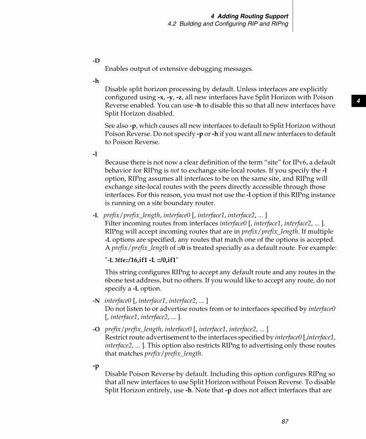
4 Adding Routing Support4.2 Building and Configuring RIP and RIPng
87
4
-DEnables output of extensive debugging messages.
-hDisable split horizon processing by default. Unless interfaces are explicitly configured using -x, -y, -z, all new interfaces have Split Horizon with Poison Reverse enabled. You can use -h to disable this so that all new interfaces have Split Horizon disabled.
See also -p, which causes all new interfaces to default to Split Horizon without Poison Reverse. Do not specify -p or -h if you want all new interfaces to default to Poison Reverse.
-l Because there is not now a clear definition of the term “site” for IPv6, a default behavior for RIPng is not to exchange site-local routes. If you specify the -l option, RIPng assumes all interfaces to be on the same site, and RIPng will exchange site-local routes with the peers directly accessible through those interfaces. For this reason, you must not use the -l option if this RIPng instance is running on a site boundary router.
-L prefix/prefix_length, interface0 [, interface1, interface2, ... ] Filter incoming routes from interfaces interface0 [, interface1, interface2, ... ]. RIPng will accept incoming routes that are in prefix/prefix_length. If multiple -L options are specified, any routes that match one of the options is accepted. A prefix/prefix_length of ::/0 is treated specially as a default route. For example:
"-L 3ffe::/16,if1 -L ::/0,if1"
This string configures RIPng to accept any default route and any routes in the 6bone test address, but no others. If you would like to accept any route, do not specify a -L option.
-N interface0 [, interface1, interface2, ... ] Do not listen to or advertise routes from or to interfaces specified by interface0 [, interface1, interface2, ... ].
-O prefix/prefix_length, interface0 [, interface1, interface2, ... ]Restrict route advertisement to the interfaces specified by interface0 [,interface1, interface2, ... ]. This option also restricts RIPng to advertising only those routes that matches prefix/prefix_length.
-p Disable Poison Reverse by default. Including this option configures RIPng so that all new interfaces to use Split Horizon without Poison Reverse. To disable Split Horizon entirely, use -h. Note that -p does not affect interfaces that are
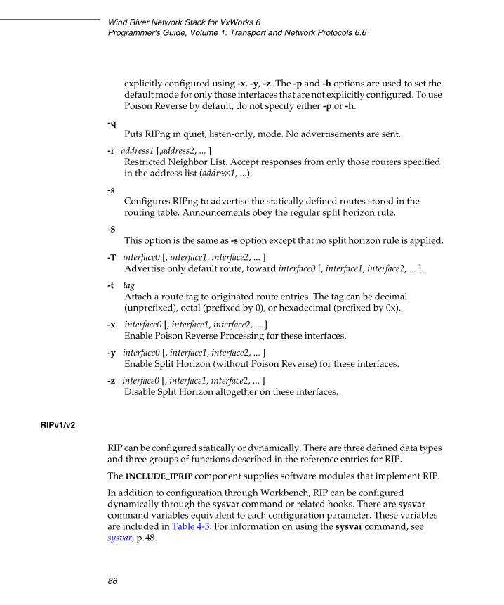
Wind River Network Stack for VxWorks 6Programmer's Guide, Volume 1: Transport and Network Protocols 6.6
88
explicitly configured using -x, -y, -z. The -p and -h options are used to set the default mode for only those interfaces that are not explicitly configured. To use Poison Reverse by default, do not specify either -p or -h.
-q Puts RIPng in quiet, listen-only, mode. No advertisements are sent.
-r address1 [,address2, ... ]Restricted Neighbor List. Accept responses from only those routers specified in the address list (address1, ...).
-sConfigures RIPng to advertise the statically defined routes stored in the routing table. Announcements obey the regular split horizon rule.
-S This option is the same as -s option except that no split horizon rule is applied.
-T interface0 [, interface1, interface2, ... ]Advertise only default route, toward interface0 [, interface1, interface2, ... ].
-t tagAttach a route tag to originated route entries. The tag can be decimal (unprefixed), octal (prefixed by 0), or hexadecimal (prefixed by 0x).
-x interface0 [, interface1, interface2, ... ]Enable Poison Reverse Processing for these interfaces.
-y interface0 [, interface1, interface2, ... ]Enable Split Horizon (without Poison Reverse) for these interfaces.
-z interface0 [, interface1, interface2, ... ]Disable Split Horizon altogether on these interfaces.
RIPv1/v2
RIP can be configured statically or dynamically. There are three defined data types and three groups of functions described in the reference entries for RIP.
The INCLUDE_IPRIP component supplies software modules that implement RIP.
In addition to configuration through Workbench, RIP can be configured dynamically through the sysvar command or related hooks. There are sysvar command variables equivalent to each configuration parameter. These variables are included in Table 4-5. For information on using the sysvar command, see sysvar, p.48.
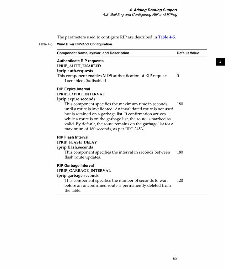
4 Adding Routing Support4.2 Building and Configuring RIP and RIPng
89
4
The parameters used to configure RIP are described in Table 4-5.
Table 4-5 Wind River RIPv1/v2 Configuration
Component Name, sysvar, and Description Default Value
Authenticate RIP requestsIPRIP_AUTH_ENABLEDiprip.auth.requestsThis component enables MD5 authentication of RIP requests.
1=enabled, 0=disabled0
RIP Expire IntervalIPRIP_EXPIRE_INTERVALiprip.expire.seconds
This component specifies the maximum time in seconds until a route is invalidated. An invalidated route is not used but is retained on a garbage list. If confirmation arrives while a route is on the garbage list, the route is marked as valid. By default, the route remains on the garbage list for a maximum of 180 seconds, as per RFC 2453.
180
RIP Flash IntervalIPRIP_FLASH_DELAYiprip.flash.seconds
This component specifies the interval in seconds between flash route updates.
180
RIP Garbage IntervalIPRIP_GARBAGE_INTERVALiprip.garbage.seconds
This component specifies the number of seconds to wait before an unconfirmed route is permanently deleted from the table.
120

Wind River Network Stack for VxWorks 6Programmer's Guide, Volume 1: Transport and Network Protocols 6.6
90
4.3 Policy-Based Routing
The policy based routing in the Wind River Network Stack makes it possible to base the route lookup decision on more than the destination address. Each virtual router can have one or more Forwarding Information Base (FIB) in policy routing mode. The default FIB is created when the virtual router is created. The default FIB cannot be deleted unless the whole virtual router is deleted. All lookups are done at the default FIB unless there is a matching policy rule that points to another FIB.
The API for policy based routing is located in installDir/components/ip_net2-6.0/ipnet2/include/ipnet_policy_routing.h.
The lookup is done according to the following scenario when policy routing is enabled:
1. A search is made for a policy routing rule matching the IP datagram being sent.
RIP Update IntervalIPRIP_UPDATE_INTERVALiprip.update.seconds
This component specifies the number of seconds between transmitting route updates over every known interface.
20
RIP Update Delta IntervalIPRIP_UPDATE_DELTAiprip.update.deltaseconds
This component specifies the variation to RIP updates in seconds. The time between each RIP broadcast or multicast message is equal to IPRIP_UPDATE_INTERVAL + random (0 to IPRIP_UPDATE_DELTA). For example, if IPRIP_UPDATE_INTERVAL is 20 and IPRIP_UPDATE_DELTA is 20, updates are sent every 20 to 40 seconds.
20
Table 4-5 Wind River RIPv1/v2 Configuration (cont’d)
Component Name, sysvar, and Description Default Value
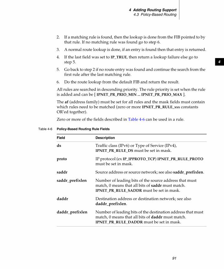
4 Adding Routing Support4.3 Policy-Based Routing
91
4
2. If a matching rule is found, then the lookup is done from the FIB pointed to by that rule. If no matching rule was found go to step 6.
3. A normal route lookup is done, if an entry is found then that entry is returned.
4. If the last field was set to IP_TRUE, then return a lookup failure else go to step 5.
5. Go back to step 2 if no route entry was found and continue the search from the first rule after the last matching rule.
6. Do the route lookup from the default FIB and return the result.
All rules are searched in descending priority. The rule priority is set when the rule is added and can be [ IPNET_PR_PRIO_MIN ... IPNET_PR_PRIO_MAX ].
The af (address family) must be set for all rules and the mask fields must contain which rules need to be matched (zero or more IPNET_PR_RULE_xxx constants OR’ed together).
Zero or more of the fields described in Table 4-6 can be used in a rule.
Table 4-6 Policy-Based Routing Rule Fields
Field Description
ds Traffic class (IPv6) or Type of Service (IPv4), IPNET_PR_RULE_DS must be set in mask.
proto IP protocol (ex IP_IPPROTO_TCP) IPNET_PR_RULE_PROTO must be set in mask.
saddr Source address or source network; see also saddr_prefixlen.
saddr_prefixlen Number of leading bits of the source address that must match, 0 means that all bits of saddr must match. IPNET_PR_RULE_SADDR must be set in mask.
daddr Destination address or destination network; see also daddr_prefixlen.
daddr_prefixlen Number of leading bits of the destination address that must match, 0 means that all bits of daddr must match. IPNET_PR_RULE_DADDR must be set in mask.
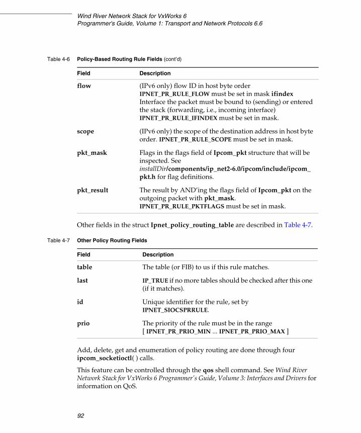
Wind River Network Stack for VxWorks 6Programmer's Guide, Volume 1: Transport and Network Protocols 6.6
92
Other fields in the struct Ipnet_policy_routing_table are described in Table 4-7.
Add, delete, get and enumeration of policy routing are done through four ipcom_socketioctl( ) calls.
This feature can be controlled through the qos shell command. See Wind River Network Stack for VxWorks 6 Programmer’s Guide, Volume 3: Interfaces and Drivers for information on QoS.
flow (IPv6 only) flow ID in host byte order IPNET_PR_RULE_FLOW must be set in mask ifindex Interface the packet must be bound to (sending) or entered the stack (forwarding, i.e., incoming interface) IPNET_PR_RULE_IFINDEX must be set in mask.
scope (IPv6 only) the scope of the destination address in host byte order. IPNET_PR_RULE_SCOPE must be set in mask.
pkt_mask Flags in the flags field of Ipcom_pkt structure that will be inspected. See installDir/components/ip_net2-6.0/ipcom/include/ipcom_pkt.h for flag definitions.
pkt_result The result by AND’ing the flags field of Ipcom_pkt on the outgoing packet with pkt_mask. IPNET_PR_RULE_PKTFLAGS must be set in mask.
Table 4-6 Policy-Based Routing Rule Fields (cont’d)
Field Description
Table 4-7 Other Policy Routing Fields
Field Description
table The table (or FIB) to us if this rule matches.
last IP_TRUE if no more tables should be checked after this one (if it matches).
id Unique identifier for the rule, set by IPNET_SIOCSPRRULE.
prio The priority of the rule must be in the range [ IPNET_PR_PRIO_MIN ... IPNET_PR_PRIO_MAX ]
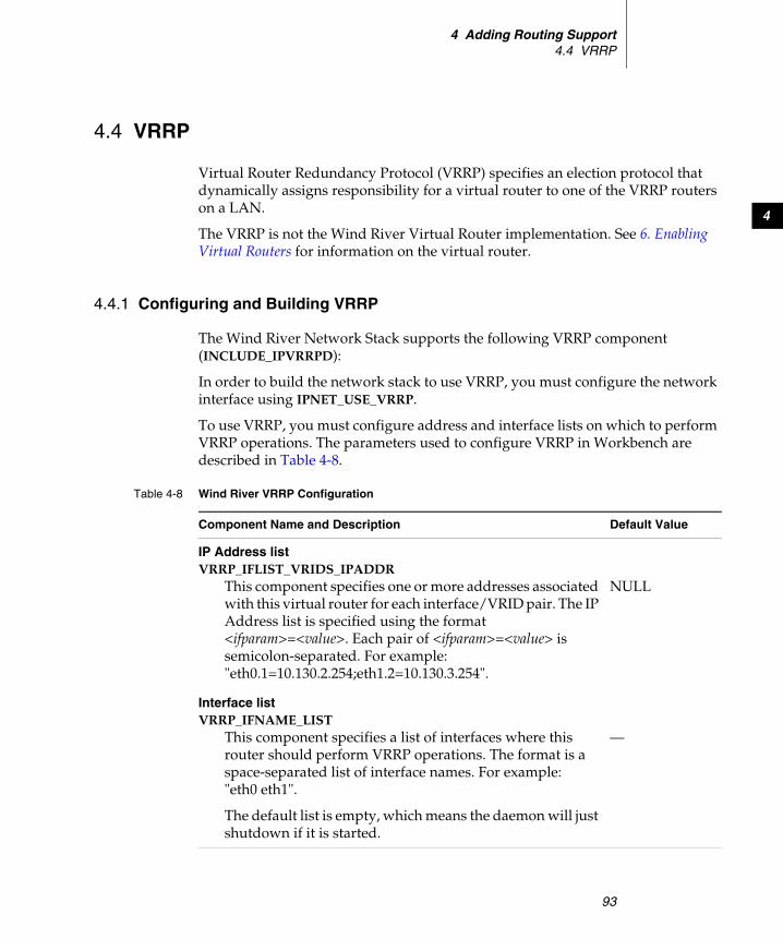
4 Adding Routing Support4.4 VRRP
93
4
4.4 VRRP
Virtual Router Redundancy Protocol (VRRP) specifies an election protocol that dynamically assigns responsibility for a virtual router to one of the VRRP routers on a LAN.
The VRRP is not the Wind River Virtual Router implementation. See 6. Enabling Virtual Routers for information on the virtual router.
4.4.1 Configuring and Building VRRP
The Wind River Network Stack supports the following VRRP component (INCLUDE_IPVRRPD):
In order to build the network stack to use VRRP, you must configure the network interface using IPNET_USE_VRRP.
To use VRRP, you must configure address and interface lists on which to perform VRRP operations. The parameters used to configure VRRP in Workbench are described in Table 4-8.
Table 4-8 Wind River VRRP Configuration
Component Name and Description Default Value
IP Address listVRRP_IFLIST_VRIDS_IPADDR
This component specifies one or more addresses associated with this virtual router for each interface/VRID pair. The IP Address list is specified using the format <ifparam>=<value>. Each pair of <ifparam>=<value> is semicolon-separated. For example: "eth0.1=10.130.2.254;eth1.2=10.130.3.254".
NULL
Interface listVRRP_IFNAME_LIST
This component specifies a list of interfaces where this router should perform VRRP operations. The format is a space-separated list of interface names. For example: "eth0 eth1".
The default list is empty, which means the daemon will just shutdown if it is started.
—
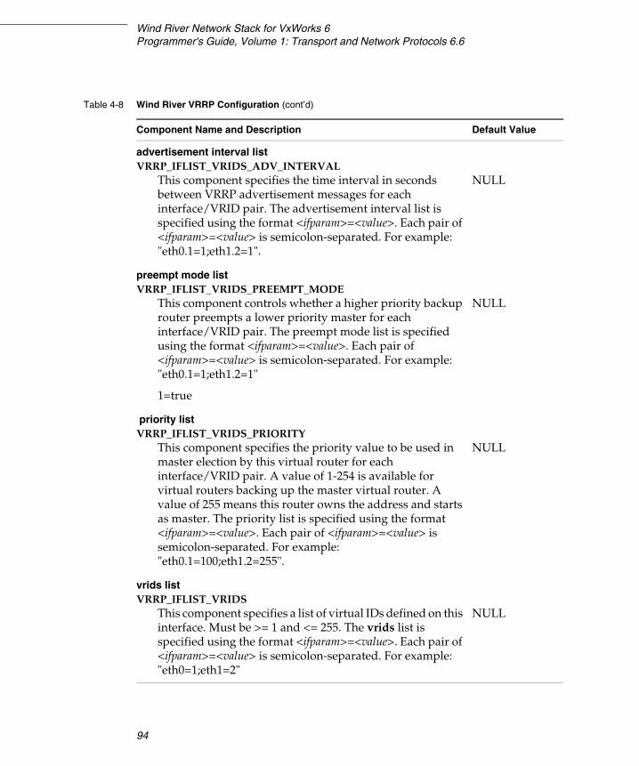
Wind River Network Stack for VxWorks 6Programmer's Guide, Volume 1: Transport and Network Protocols 6.6
94
advertisement interval listVRRP_IFLIST_VRIDS_ADV_INTERVAL
This component specifies the time interval in seconds between VRRP advertisement messages for each interface/VRID pair. The advertisement interval list is specified using the format <ifparam>=<value>. Each pair of <ifparam>=<value> is semicolon-separated. For example: "eth0.1=1;eth1.2=1".
NULL
preempt mode listVRRP_IFLIST_VRIDS_PREEMPT_MODE
This component controls whether a higher priority backup router preempts a lower priority master for each interface/VRID pair. The preempt mode list is specified using the format <ifparam>=<value>. Each pair of <ifparam>=<value> is semicolon-separated. For example:"eth0.1=1;eth1.2=1"
1=true
NULL
priority listVRRP_IFLIST_VRIDS_PRIORITY
This component specifies the priority value to be used in master election by this virtual router for each interface/VRID pair. A value of 1-254 is available for virtual routers backing up the master virtual router. A value of 255 means this router owns the address and starts as master. The priority list is specified using the format <ifparam>=<value>. Each pair of <ifparam>=<value> is semicolon-separated. For example:"eth0.1=100;eth1.2=255".
NULL
vrids listVRRP_IFLIST_VRIDS
This component specifies a list of virtual IDs defined on this interface. Must be >= 1 and <= 255. The vrids list is specified using the format <ifparam>=<value>. Each pair of <ifparam>=<value> is semicolon-separated. For example:"eth0=1;eth1=2"
NULL
Table 4-8 Wind River VRRP Configuration (cont’d)
Component Name and Description Default Value
4 Adding Routing Support4.5 Fast Path
95
4
4.5 Fast Path
Fast path, also known as fast IP-forwarding, is a mechanism that intercepts packets (either IPv4 or IPv6) before they are passed up to IP. If the packet is destined for a location known to the fast path route cache (also known as the FIB, the forwarding information base), the application forwards the packet. If the destination is unknown to the FIB, the application leaves the packet to IP.
This two-level approach lets you bypass regular IP processing for selected packets. This improves performance on packets headed for destinations known to the FIB. It reduces performance for all other packets, but overall router performance is improved if most traffic is headed for destinations known to the FIB.
The Wind River Network Stack supplies two varieties of fast path—generic and Ethernet—that are tightly integrated with the routing engine and are defined by default when the network stack is built.
In Wind River VxWorks Platforms, these components are defined in the following file:
installDir/components/ip_net2-6.6/ipnet/config/ipnet_config.h
4.5.1 Generic Fast Path
The IPNET_FASTPATH component is included by default. This component configures the network stack to use IPv4/IPv6 fast path routing code. This fast path is slower that the Ethernet fast path, but it works for all interface types (incoming and outgoing), and it will also work together with Wind River Firewall and Wind River NAT.
4.5.2 Ethernet Fast Path
The IPNET_ETH_FASTPATH component is included by default. This component configures the network stack to use IPv4/IPv6 Ethernet fast path routing code. The Ethernet fast path is faster than the generic fast path, but both the incoming (ingress) and the outgoing (egress) interfaces must be Ethernet. The outgoing interface must have the link2 (IP_IFF_LINK2) bit set to create the Ethernet fast path flow.
Wind River Network Stack for VxWorks 6Programmer's Guide, Volume 1: Transport and Network Protocols 6.6
96
4.6 Adjusting the Route Table
The route command is a utility for manually making changes to the route table or route settings.
4.6.1 Route Shell Command
The route command is sometimes used in conjunction with several other components. In those cases, its use is described in the relevant section of this guide.
The route command is available when using routing sockets. It is included in the network stack by including the INCLUDE_IPROUTE_CMD component.
route
Name
route - a utility to manually manipulate network routing
Synopsis
The syntax for the general route command is as follows:
route [-n] [-nollinfo] [-V routetab] subcommand [[modifiers] args]
Description
The route utility supports a limited number of general options, but a rich command language enables the user to specify any arbitrary request that could be delivered via the programmatic interface.
Options
The options for route are described in Table 4-9.
NOTE: If Wind River Firewall is included in the Platform build, the Ethernet fast path feature is disabled. Make sure the firewall is excluded in your config.mk if you intend to use the Ethernet fast path feature.
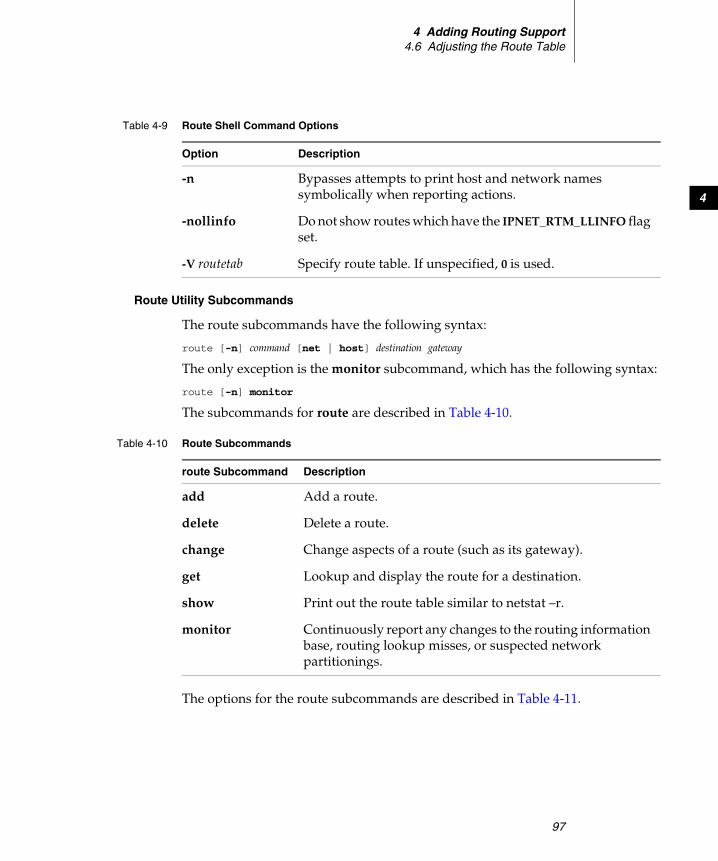
4 Adding Routing Support4.6 Adjusting the Route Table
97
4
Route Utility Subcommands
The route subcommands have the following syntax:
route [-n] command [net | host] destination gateway
The only exception is the monitor subcommand, which has the following syntax:
route [-n] monitor
The subcommands for route are described in Table 4-10.
The options for the route subcommands are described in Table 4-11.
Table 4-9 Route Shell Command Options
Option Description
-n Bypasses attempts to print host and network names symbolically when reporting actions.
-nollinfo Do not show routes which have the IPNET_RTM_LLINFO flag set.
-V routetab Specify route table. If unspecified, 0 is used.
Table 4-10 Route Subcommands
route Subcommand Description
add Add a route.
delete Delete a route.
change Change aspects of a route (such as its gateway).
get Lookup and display the route for a destination.
show Print out the route table similar to netstat –r.
monitor Continuously report any changes to the routing information base, routing lookup misses, or suspected network partitionings.
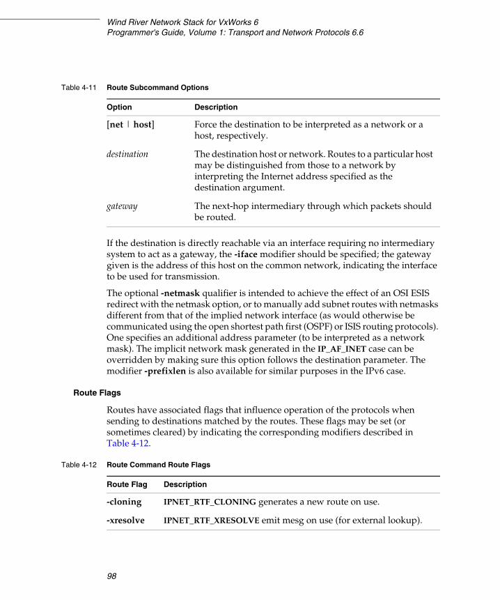
Wind River Network Stack for VxWorks 6Programmer's Guide, Volume 1: Transport and Network Protocols 6.6
98
If the destination is directly reachable via an interface requiring no intermediary system to act as a gateway, the -iface modifier should be specified; the gateway given is the address of this host on the common network, indicating the interface to be used for transmission.
The optional -netmask qualifier is intended to achieve the effect of an OSI ESIS redirect with the netmask option, or to manually add subnet routes with netmasks different from that of the implied network interface (as would otherwise be communicated using the open shortest path first (OSPF) or ISIS routing protocols). One specifies an additional address parameter (to be interpreted as a network mask). The implicit network mask generated in the IP_AF_INET case can be overridden by making sure this option follows the destination parameter. The modifier -prefixlen is also available for similar purposes in the IPv6 case.
Route Flags
Routes have associated flags that influence operation of the protocols when sending to destinations matched by the routes. These flags may be set (or sometimes cleared) by indicating the corresponding modifiers described in Table 4-12.
Table 4-11 Route Subcommand Options
Option Description
[net | host] Force the destination to be interpreted as a network or a host, respectively.
destination The destination host or network. Routes to a particular host may be distinguished from those to a network by interpreting the Internet address specified as the destination argument.
gateway The next-hop intermediary through which packets should be routed.
Table 4-12 Route Command Route Flags
Route Flag Description
-cloning IPNET_RTF_CLONING generates a new route on use.
-xresolve IPNET_RTF_XRESOLVE emit mesg on use (for external lookup).
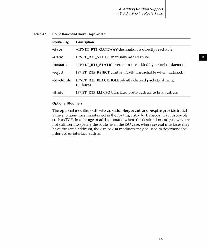
4 Adding Routing Support4.6 Adjusting the Route Table
99
4
Optional Modifiers
The optional modifiers -rtt, -rttvar, -mtu, -hopcount, and -expire provide initial values to quantities maintained in the routing entry by transport level protocols, such as TCP. In a change or add command where the destination and gateway are not sufficient to specify the route (as in the ISO case, where several interfaces may have the same address), the -ifp or -ifa modifiers may be used to determine the interface or interface address.
-iface ~IPNET_RTF_GATEWAY destination is directly reachable.
-static IPNET_RTF_STATIC manually added route.
-nostatic ~IPNET_RTF_STATIC pretend route added by kernel or daemon.
-reject IPNET_RTF_REJECT emit an ICMP unreachable when matched.
-blackhole IPNET_RTF_BLACKHOLE silently discard packets (during updates)
-llinfo IPNET_RTF_LLINFO translates proto address to link address
Table 4-12 Route Command Route Flags (cont’d)
Route Flag Description

Wind River Network Stack for VxWorks 6Programmer's Guide, Volume 1: Transport and Network Protocols 6.6
100
101
5Working with Routing Sockets
5.1 Introduction 101
5.2 Getting Started with Routing Sockets 103
5.3 Preparing and Processing Routing Socket Messages 104
5.4 Extracting Information from a Routing Socket Message 114
5.5 Building a Routing Socket Message 116
5.1 Introduction
Routing sockets provide a two-way communication interface to the route table. Using a routing socket, an application can monitor and make changes to the contents of the routing table.
Traditionally, a route table stored only one entry per destination network. For IPv4, a destination network is identified by an IPv4 address and a netmask value. For IPv6, a destination network is identified by an IPv6 address and a prefix value. A route table entry associates this destination with a gateway on a local network or with an interface on a local network. In previous route table implementations, adding a route entry to the table failed if the table already contained an entry for that destination.
The route table in the current network stack has been enhanced to store multiple same-destination routes that differ by gateway value or network mask. Adding a
Wind River Network Stack for VxWorks 6Programmer's Guide, Volume 1: Transport and Network Protocols 6.6
102
route entry to a table that already contains an entry for that destination can succeed, provided the new entry differs from the existing entry (or entries) in its gateway value or network mask. Policy routing adds even more flexibility to a lookup by adding type of service (TOS) (IPv4), traffic class (IPv6), protocol, source address or network, destination address or network, and traffic flow (IPv6) as selectors.
When IP queries the route table, it expects to get back only one route. To satisfy this expectation, the route table ranks multiple same-destination routes. The highest ranked route, known as the primary or representative route for the destination, is the route reported to IP. How the system ranks same-destination routes depends on how you build the code.
Ranking Routes Using ECMP Routing
Multiple same-destination route entries are ranked by hopcount field (rmx_hopcount). The ones with lower hopcount have higher precedence. If there are multiple same-destination entries with the same hopcount, selection is done through an algorithm called Equal-Cost Multipath (ECMP) which is described in RFC 2991, Multipath Issues in Unicast and Multicast Next-Hop Selection. Two of the algorithms described in RFC 2991 are implemented:
■ Modulo-N Hash■ Highest Random Weight
Modulo-N Hash is the fastest, but adding or removing a same-destination route tends to change which route entry is returned for a specific traffic flow. Highest Random Weight will always return the same route entry for a specific flow after a remove operation unless the entry that used to be returned was the one removed. The same entry or the new entry is selected after an add operation. The probability for the new entry to be selected over the old one is:
1/N
where N is number of same-destination entries, including the added entry.
Location of net/route.h
This chapter makes reference to the net/route.h file. The full pathname is:
installDir/vxworks-6.x/target/usr/h/wrn/coreip/net/route.h
5 Working with Routing Sockets5.2 Getting Started with Routing Sockets
103
5
5.2 Getting Started with Routing Sockets
This section describes how to add routing socket support to VxWorks and how to set up a routing socket.
5.2.1 Configuring VxWorks for Routing Sockets
The Wind River Network Stack supports the routing socket support component.
The INCLUDE_IPNET_USE_ROUTESOCK component pulls in the routing socket interface.
There are no configuration parameters or externally callable functions directly associated with this component.
5.2.2 Setting up a Routing Socket
Setting up a routing socket requires a socket( ) call. There is no need to make an explicit bind( ) or connect( ) call for a routing socket. After creating a routing socket, you may want to configure the socket options.
Creating a Routing Socket
To create a socket descriptor for use as a socket in the routing domain, call socket( ) with a domain value of AF_ROUTE, a type value of SOCK_RAW, and a protocol value of 0 (zero). For example:
myRouteSocket = socket (AF_ROUTE, SOCK_RAW, 0);if (routeSocket < 0)
{your response code for the socket call failure}
Setting Socket Options on a Routing Socket
After you have the socket descriptor, you can make it non-blocking by making an FIONBIO call to ioctl( ).
For example:
on = 1;if (ioctl (myRouteSocket, FIONBIO, (int) &on) == -1) {
your response code for the ioctl call failure}
Wind River Network Stack for VxWorks 6Programmer's Guide, Volume 1: Transport and Network Protocols 6.6
104
Another useful option is SO_USELOOPBACK, which is enabled by default. When this option is cleared, you will not hear the response to the messages that you write to your socket.
on = 0;if (setsockopt (myRtSock, SOL_SOCKET, SO_USELOOPBACK, (char *)&on,
sizeof (on)) == ERROR) {your response code for the setsockopt call failure
}
A routing socket typically only sends a response if the requested operation fails. The only exceptions are the GET messages, which also send a response with the retrieved results (if successful). Disabling this option will require a separate routing socket to read the search results.
5.2.3 Disabling Routing Sockets
To build a network stack without routing sockets, you need to edit the network stack configuration header file. Routing sockets are enabled by default in:
installDir/components/ip_net2-6.x/ipnet2/config/ipnet_config.h
To disable routing sockets:
1. Open installDir/components/ip_net2-6.x /ipnet2/config/ipnet_config.h.
2. Comment out the routing sockets define:
#define IPNET_USE_ROUTESOCK
3. Save the file.
4. Rebuild the project.
5.3 Preparing and Processing Routing Socket Messages
When preparing or processing a routing socket message, you can assume that it consists of a fixed-length header followed by up to eight socket address structures. For most routing socket messages, the fixed-length header is described by an rt_msghdr structure, which is defined in net/route.h.
This structure describes the fixed length message header for all but the following routing socket message types:
5 Working with Routing Sockets5.3 Preparing and Processing Routing Socket Messages
105
5
■ RTM_NEWADDR■ RTM_DELADDR■ RTM_IFINFO■ RTM_IFANNOUNCE
For RTM_NEWADDR or RTM_DELADDR messages, the message header is described by the ifa_msghdr structure defined in net/route.h.
For RTM_IFINFO messages, the message header is described by the if_msghdr structure defined in net/route.h.
For RTM_IFANNOUNCE messages, the message header is described by the if_announcemsghdr structure defined in net/route.h.
5.3.1 Case/Switch Processing for Received Messages
The first three members of the routing socket message header structures are all of the same type and carry the same meaning. Thus, when a message first arrives on a socket, you can read the routing socket message type value using any structure overlay that is convenient. To make it easier to do this, you could receive the message into a union. Consider the following code fragment skeleton:1
#include <net/if.h>#include <net/route.h>
/* sizeof the msglen, version and type fields that all AF_ROUTE messages must contain */ #define AF_ROUTE_MIN_MSG_LEN 4
union af_route_msg { struct if_msghdr if_hdr; struct ifa_msghdr ifa_hdr; struct rt_msghdr rt_hdr; struct if_announcemsghdr if_announcehdr; };
int input_af_route_msg(void *msg_ptr, int msg_len) { union af_route_msg *msg = msg_ptr; if (msg_len < AF_ROUTE_MIN_MSG_LEN) /* Message is too short for being a AF_ROUTE message */ return MALFORMED_MSG_ERROR_CODE;
if (msg_len < msg->rt_hdr.rtm_msglen) /* Message is truncated or malformed */ return TRUNCATED_MSG_ERROR_CODE;
switch (msg->rt_hdr.rtm_type)
1. Although this union is useful for receiving messages, it would waste resources to use it when creating a routing socket message.
Wind River Network Stack for VxWorks 6Programmer's Guide, Volume 1: Transport and Network Protocols 6.6
106
{ case RTM_ADD: /* Handle add message, reference message through msg->rt_hdr */ break; case RTM_NEWADDR: /* Handle new address message, reference message through msg->ifa_hdr */ break; case RTM_IFINFO: /* Handle interface status change, reference message through msg->if_hdr */ break; case RTM_IFANNOUNCE /* Handle interface status change, reference message through msg->if_announcehdr */ break; /* case statements for all other messages types goes here */ default: /* Unsupported or invalid message type */ return INVALID_MSG_TYPE_ERRO_CODE; }}
5.3.2 Types of Routing Socket Messages
Routing sockets on a VxWorks target running a host stack build use the standard set of routing socket messages described in the routing sockets section of TCP/IP Illustrated, Volume 2, with some exceptions. For instance, interface indices are 32 bits, the rt_msghdr structure has a new element with a route table index associated with virtual router functionality, and the rt_metrics and if_data substructures occurring in rt_msghdr and if_msghdr messages are different. See the net/route.h and net/if.h header files for the structure definitions.
Constants for the message types are defined in net/route.h. The key at the top of the list indicates the message structure and whether the message can be sent or received by the network stack.
/* T = message can be sent to IPNET F = message can be sent from IPNET 1 = message format is struct rt_msghdr 2 = message format is struct ifa_msghdr 3 = message format is struct if_msghdr 4 = message format is struct if_announcemsghdr */#define RTM_ADD 0x1 /* TF1 Add route */#define RTM_DELETE 0x2 /* TF1 Delete route */#define RTM_CHANGE 0x3 /* TF1 Change in metric or flags */#define RTM_GET 0x4 /* TF1 Report metrics and other route information */#define RTM_LOOSING 0x5 /* F1 Kernel suspects route is failing */#define RTM_REDIRECT 0x6 /* F1 Kernel told to use a different route */
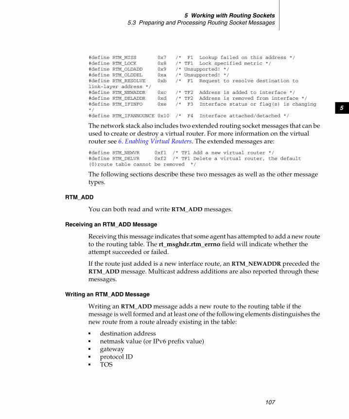
5 Working with Routing Sockets5.3 Preparing and Processing Routing Socket Messages
107
5
#define RTM_MISS 0x7 /* F1 Lookup failed on this address */#define RTM_LOCK 0x8 /* TF1 Lock specified metric */#define RTM_OLDADD 0x9 /* Unsupported! */#define RTM_OLDDEL 0xa /* Unsupported! */#define RTM_RESOLVE 0xb /* F1 Request to resolve destination to link-layer address */#define RTM_NEWADDR 0xc /* TF2 Address is added to interface */#define RTM_DELADDR 0xd /* TF2 Address is removed from interface */#define RTM_IFINFO 0xe /* F3 Interface status or flag(s) is changing */#define RTM_IFANNOUNCE 0x10 /* F4 Interface attached/detached */
The network stack also includes two extended routing socket messages that can be used to create or destroy a virtual router. For more information on the virtual router see 6. Enabling Virtual Routers. The extended messages are:
#define RTM_NEWVR 0xf1 /* TF1 Add a new virtual router */#define RTM_DELVR 0xf2 /* TF1 Delete a virtual router, the default (0)route table cannot be removed */
The following sections describe these two messages as well as the other message types.
RTM_ADD
You can both read and write RTM_ADD messages.
Receiving an RTM_ADD Message
Receiving this message indicates that some agent has attempted to add a new route to the routing table. The rt_msghdr.rtm_errno field will indicate whether the attempt succeeded or failed.
If the route just added is a new interface route, an RTM_NEWADDR preceded the RTM_ADD message. Multicast address additions are also reported through these messages.
Writing an RTM_ADD Message
Writing an RTM_ADD message adds a new route to the routing table if the message is well formed and at least one of the following elements distinguishes the new route from a route already existing in the table:
■ destination address ■ netmask value (or IPv6 prefix value) ■ gateway ■ protocol ID ■ TOS

Wind River Network Stack for VxWorks 6Programmer's Guide, Volume 1: Transport and Network Protocols 6.6
108
To monitor the success of an add request under the standard message set, check the errno value, which is available from the send results.
The header for an RTM_ADD message is described by an rt_msghdr structure, which is defined in net/route.h.
RTM_DELETE
You can both read and write RTM_DELETE messages.
Receiving an RTM_DELETE Message
Receiving this message indicates that some agent has tried to delete a route from the routing table. To know whether the attempt succeeded, check the rtm_errno field in the message header.
If the deleted route is an interface route, this RTM_DELETE is followed by an RTM_DELADDR. Multicast address deletions are also reported through these messages.
Writing an RTM_DELETE Message
Writing an RTM_DELETE message deletes a route from the routing table if the message is well formed and if it matches a route in the table. The criteria by which a match is made are:
■ destination address
■ netmask value (or IPv6 prefix value)
■ gateway (a value of NULL functions as a wildcard)
■ protocol ID (a value of 0 functions as a wildcard)
■ TOS (a value of -1 functions as a wildcard)
You need to specify a protocol ID, a TOS value, and a gateway value only if you want to delete a secondary route. To delete the primary route, it is enough to specify only the destination address and netmask value.
To check the success of a delete request, monitor the socket for an incoming RTM_DELETE.
The header for an RTM_DELETE message is described by an rt_msghdr structure, which is defined in net/route.h.
5 Working with Routing Sockets5.3 Preparing and Processing Routing Socket Messages
109
5
RTM_CHANGE
You can both read and write RTM_CHANGE messages.
Receiving an RTM_CHANGE Message
Receiving this message indicates that an agent has changed the gateway, metrics, or some other property associated with the route to the specified destination.
Writing an RTM_CHANGE Message
Writing this message lets you change the gateway or metrics associated with the route to the specified destination, which is identified by:
■ destination address
■ netmask value (or IPv6 prefix value)
■ gateway (a value of NULL does not function as a wildcard)
■ protocol ID (a value of 0 functions as a wildcard)
■ TOS (a value of -1 functions as a wildcard)
You need to specify a protocol ID and TOS value only if you want to modify a particular route. You can set these to wildcard values if matching on them is not important to you. If multiple routes exist, you must specify a gateway in order to select the matching entry.
All information in the message other than the destination and netmask are interpreted as values that you want written into the existing route entry. If only one route exists for a destination address and netmask, you can change the gateway by providing a new gateway value. If multiple routes exist, then you cannot change the gateway because the gateway is used to select the route that is the entry you want changed.
The header for an RTM_CHANGE message is described by an rt_msghdr structure, which is defined in net/route.h.
RTM_GET
You can both read and write RTM_GET messages. Writing this message checks the route table for a route to the specified destination. To check the success of the request, monitor the socket for an incoming RTM_GET message. If the request was successful, the route information is appended to the message header. If the request
Wind River Network Stack for VxWorks 6Programmer's Guide, Volume 1: Transport and Network Protocols 6.6
110
failed to find a matching route, this is indicated in the rtm_errno field of the message header.
The criteria by which a match is made are:
■ destination address ■ netmask value (or IPv6 prefix value)■ gateway (a value of NULL functions as a wildcard) ■ protocol ID (a value of 0 functions as a wildcard) ■ TOS (a value of -1 functions as a wildcard)
You need to specify the protocol ID, the TOS value, and the gateway value if you want to retrieve a secondary route. To retrieve the primary route, you need to specify only the destination address, and optionally, the netmask (or prefix) value. If the netmask value is not specified, the code does a longest-match lookup of the destination, as it would if sending a packet, rather than searching for an exact match with a specified destination-netmask pair.
The header for an RTM_GET message is described by an rt_msghdr structure, which is defined in net/route.h.
RTM_LOSING
This is a read-only message. It indicates that the specified route might not still be valid. TCP originates this message after four or more consecutive failed retransmissions over the route.
The header for an RTM_LOSING message is described by an rt_msghdr structure, which is defined in net/route.h.
RTM_REDIRECT
This is a read-only message. It indicates that ICMP has sent a redirect for the specified destination, the address appended to the header in the RTA_DST location. The address of a preferred gateway is appended to the message in the RTA_GATEWAY location. The address of the author for the redirect message is appended to the header in the RTA_AUTHOR location.
To know whether this message indicates a change in the contents of the route table, check the rtm_errno value in the message header. A non-zero rtm_errno value indicates a failed RTM_REDIRECT. A zero indicates a successful RTM_REDIRECT. In this case, the table will contain a new host-specific route. This new host route is
5 Working with Routing Sockets5.3 Preparing and Processing Routing Socket Messages
111
5
created only if the original mis-directed route was a non-host (or network) route. Otherwise, that existing host route is modified.
The header for an RTM_REDIRECT message is described by an rt_msghdr structure, which is defined in net/route.h.
RTM_MISS
This is a read-only message. It indicates that some agent’s search of the route table failed to find a route to the specified destination. The header for an RTM_MISS message is described by an rt_msghdr structure, which is defined in net/route.h.
RTM_LOCK
You can both read and write RTM_LOCK messages. Receiving this message indicates that the metrics associated with the specified route are now locked. Writing this message locks the metrics for the specified route. The header for an RTM_LOCK message is described by an rt_msghdr structure, which is defined in net/route.h.
RTM_RESOLVE
This is a read-only message. Receiving this message indicates a request to resolve destination address to a link-layer address. The header for an RTM_RESOLVE message is described by an rt_msghdr structure, which is defined in net/route.h.
RTM_NEWADDR
This is a read-only message. This message is the first of two messages associated with adding an IP address to an interface. The second, an RTM_ADD, describes the route through that interface to the subnet associated with the address.
For an RTM_NEWADDR message, the message header is described by the ifa_msghdr structure, which is defined in net/route.h.

Wind River Network Stack for VxWorks 6Programmer's Guide, Volume 1: Transport and Network Protocols 6.6
112
RTM_DELADDR
This is a read-only message. This message is the second of two messages associated with deleting an IP address from an interface. The first, an RTM_DELETE, describes the now deleted route through that interface to the subnet with the associated address.
For an RTM_DELADDR message, the message header is described by the ifa_msghdr structure, which is defined in net/route.h.
RTM_IFINFO
This is a read-only message. This message reports a change in status for the specified interface. All routes through that interface are affected by the change. For an RTM_IFINFO message, the message header is described by an if_msghdr structure, which is defined in if.h.
RTM_IFANNOUNCE
This is a read-only message. It announces the arrival or departure of a network interface. The header for an RTM_IFANNOUNCE message is described by an if_announcemsghdr structure, which is defined in if.h.
Extended Messages for Virtual Routing
A new virtual router can be created and destroyed in various ways. For more information see 6. Enabling Virtual Routers.
RTM_NEWVR
You can both read and write RTM_NEWVR messages. Adds a new virtual routing domain. The header for an RTM_NEWVR message is described by an rt_msghdr structure, which is defined in net/route.h.
RTM_DELVR
You can both read and write RTM_DELVR messages. Deletes a virtual routing domain. The default route table (for VR 0) cannot be removed. The header for an RTM_DELVR message is described by an rt_msghdr structure, which is defined in net/route.h.
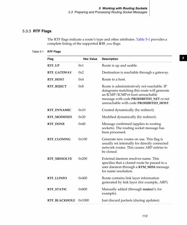
5 Working with Routing Sockets5.3 Preparing and Processing Routing Socket Messages
113
5
5.3.3 RTF Flags
The RTF flags indicate a route’s type and other attributes. Table 5-1 provides a complete listing of the supported RTF_name flags.
Table 5-1 RTF Flags
Flag Hex Value Description
RTF_UP 0x1 Route is up and usable.
RTF_GATEWAY 0x2 Destination is reachable through a gateway.
RTF_HOST 0x4 Route to a host.
RTF_REJECT 0x8 Route is administratively not reachable. IP datagrams matching this route will generate an ICMP/ICMPv6 host unreachable message with code PROHIBITED_NET or net unreachable with code PROHIBITED_HOST.
RTF_DYNAMIC 0x10 Created dynamically (by redirect).
RTF_MODIFIED 0x20 Modified dynamically (by redirect).
RTF_DONE 0x40 Message confirmed (applies to routing sockets). The routing socket message has been processed.
RTF_CLONING 0x100 Generate new routes on use. This flag is usually set internally for directly connected network routes. This causes ARP entries to be cloned.
RTF_XRESOLVE 0x200 External daemon resolves name. This specifies that a cloned route be passed to a user daemon through a RTM_MISS message for name resolution.
RTF_LLINFO 0x400 Route contains link layer information generated by link layer (for example, ARP).
RTF_STATIC 0x800 Manually added (through routec( ), for example).
RTF_BLACKHOLE 0x1000 Just discard packets (during updates).
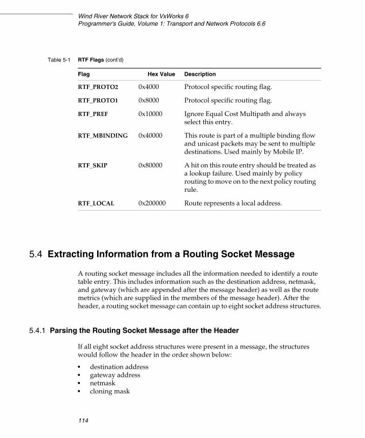
Wind River Network Stack for VxWorks 6Programmer's Guide, Volume 1: Transport and Network Protocols 6.6
114
5.4 Extracting Information from a Routing Socket Message
A routing socket message includes all the information needed to identify a route table entry. This includes information such as the destination address, netmask, and gateway (which are appended after the message header) as well as the route metrics (which are supplied in the members of the message header). After the header, a routing socket message can contain up to eight socket address structures.
5.4.1 Parsing the Routing Socket Message after the Header
If all eight socket address structures were present in a message, the structures would follow the header in the order shown below:
■ destination address■ gateway address■ netmask ■ cloning mask
RTF_PROTO2 0x4000 Protocol specific routing flag.
RTF_PROTO1 0x8000 Protocol specific routing flag.
RTF_PREF 0x10000 Ignore Equal Cost Multipath and always select this entry.
RTF_MBINDING 0x40000 This route is part of a multiple binding flow and unicast packets may be sent to multiple destinations. Used mainly by Mobile IP.
RTF_SKIP 0x80000 A hit on this route entry should be treated as a lookup failure. Used mainly by policy routing to move on to the next policy routing rule.
RTF_LOCAL 0x200000 Route represents a local address.
Table 5-1 RTF Flags (cont’d)
Flag Hex Value Description
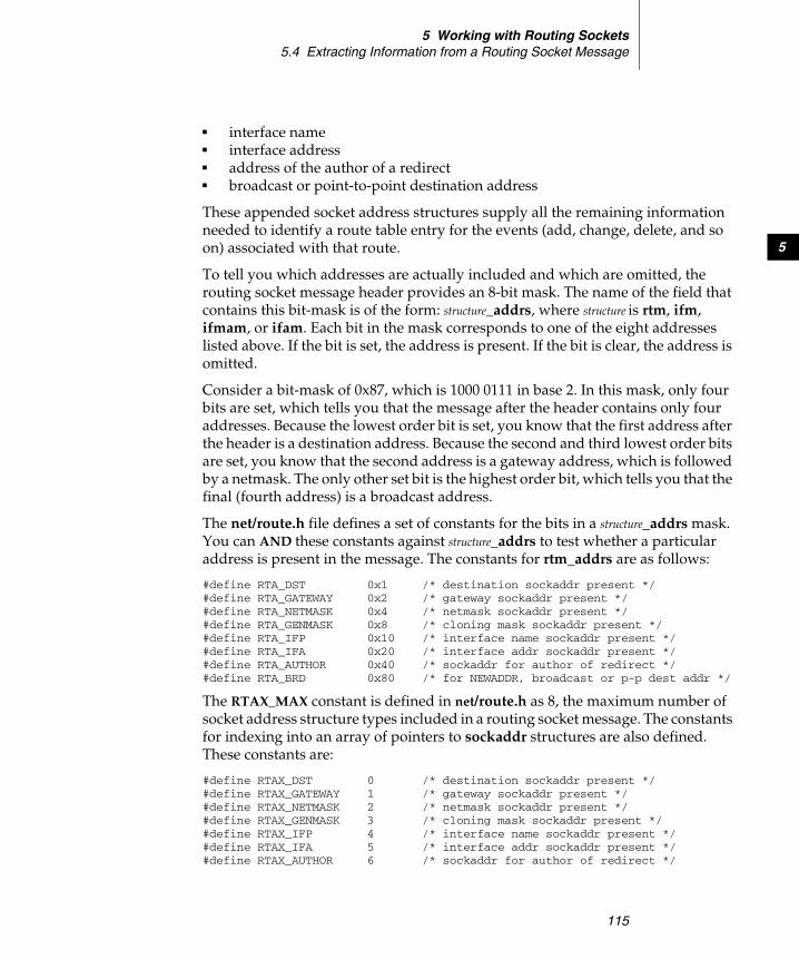
5 Working with Routing Sockets5.4 Extracting Information from a Routing Socket Message
115
5
■ interface name■ interface address■ address of the author of a redirect■ broadcast or point-to-point destination address
These appended socket address structures supply all the remaining information needed to identify a route table entry for the events (add, change, delete, and so on) associated with that route.
To tell you which addresses are actually included and which are omitted, the routing socket message header provides an 8-bit mask. The name of the field that contains this bit-mask is of the form: structure_addrs, where structure is rtm, ifm, ifmam, or ifam. Each bit in the mask corresponds to one of the eight addresses listed above. If the bit is set, the address is present. If the bit is clear, the address is omitted.
Consider a bit-mask of 0x87, which is 1000 0111 in base 2. In this mask, only four bits are set, which tells you that the message after the header contains only four addresses. Because the lowest order bit is set, you know that the first address after the header is a destination address. Because the second and third lowest order bits are set, you know that the second address is a gateway address, which is followed by a netmask. The only other set bit is the highest order bit, which tells you that the final (fourth address) is a broadcast address.
The net/route.h file defines a set of constants for the bits in a structure_addrs mask. You can AND these constants against structure_addrs to test whether a particular address is present in the message. The constants for rtm_addrs are as follows:
#define RTA_DST 0x1 /* destination sockaddr present */#define RTA_GATEWAY 0x2 /* gateway sockaddr present */#define RTA_NETMASK 0x4 /* netmask sockaddr present */#define RTA_GENMASK 0x8 /* cloning mask sockaddr present */#define RTA_IFP 0x10 /* interface name sockaddr present */#define RTA_IFA 0x20 /* interface addr sockaddr present */#define RTA_AUTHOR 0x40 /* sockaddr for author of redirect */#define RTA_BRD 0x80 /* for NEWADDR, broadcast or p-p dest addr */
The RTAX_MAX constant is defined in net/route.h as 8, the maximum number of socket address structure types included in a routing socket message. The constants for indexing into an array of pointers to sockaddr structures are also defined. These constants are:
#define RTAX_DST 0 /* destination sockaddr present */#define RTAX_GATEWAY 1 /* gateway sockaddr present */#define RTAX_NETMASK 2 /* netmask sockaddr present */#define RTAX_GENMASK 3 /* cloning mask sockaddr present */#define RTAX_IFP 4 /* interface name sockaddr present */#define RTAX_IFA 5 /* interface addr sockaddr present */#define RTAX_AUTHOR 6 /* sockaddr for author of redirect */
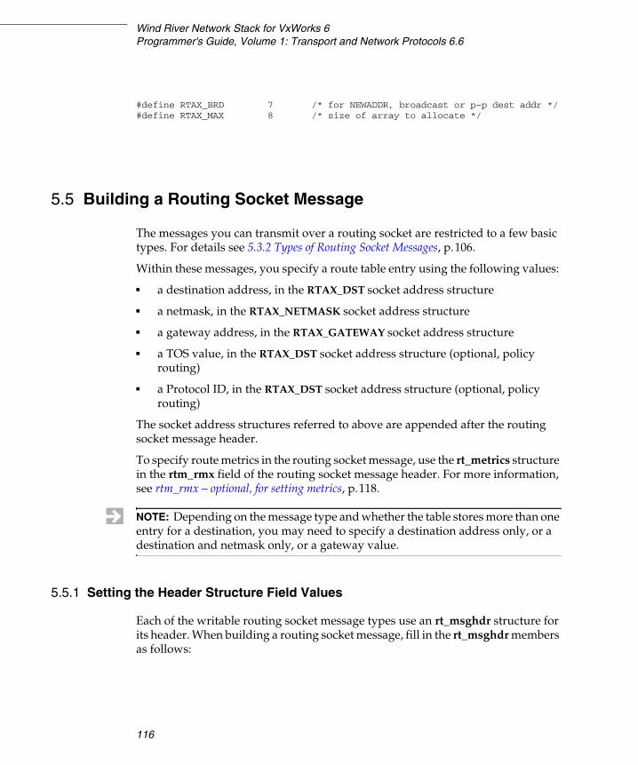
Wind River Network Stack for VxWorks 6Programmer's Guide, Volume 1: Transport and Network Protocols 6.6
116
#define RTAX_BRD 7 /* for NEWADDR, broadcast or p-p dest addr */#define RTAX_MAX 8 /* size of array to allocate */
5.5 Building a Routing Socket Message
The messages you can transmit over a routing socket are restricted to a few basic types. For details see 5.3.2 Types of Routing Socket Messages, p.106.
Within these messages, you specify a route table entry using the following values:
■ a destination address, in the RTAX_DST socket address structure
■ a netmask, in the RTAX_NETMASK socket address structure
■ a gateway address, in the RTAX_GATEWAY socket address structure
■ a TOS value, in the RTAX_DST socket address structure (optional, policy routing)
■ a Protocol ID, in the RTAX_DST socket address structure (optional, policy routing)
The socket address structures referred to above are appended after the routing socket message header.
To specify route metrics in the routing socket message, use the rt_metrics structure in the rtm_rmx field of the routing socket message header. For more information, see rtm_rmx – optional, for setting metrics, p.118.
5.5.1 Setting the Header Structure Field Values
Each of the writable routing socket message types use an rt_msghdr structure for its header. When building a routing socket message, fill in the rt_msghdr members as follows:
NOTE: Depending on the message type and whether the table stores more than one entry for a destination, you may need to specify a destination address only, or a destination and netmask only, or a gateway value.
5 Working with Routing Sockets5.5 Building a Routing Socket Message
117
5
rtm_msglen – required in an outgoing messageExpects the length of the entire socket message. The reported size includes the header plus all appended socket addressees. The best time to assign this value is after you have appended the last address to the routing socket message. See below, rtm_addrs – required in an outgoing message, p.117.
rtm_version – required in an outgoing messageExpects the version ID of the routing socket message. The current version is 4.
rtm_type – required in an outgoing messageExpects a value indicating the routing socket message type RTM_type.
These message types (described in 5.3.2 Types of Routing Socket Messages, p.106) let you add, change, delete, get, or lock an entry in the route table. The response to an add, change, delete, get, or lock message is an incoming add, change, lock, get, or delete message on your socket. You can determine the success or failure of your request by reading the rtm_errno field in the header of the response message.
rtm_index – read-only, ignored in outgoing messagesThe index value for the associated network interface.
rtm_flags – for add and delete messages onlyIn an outgoing message, this field expects an integer value whose bits describe the route. Included in this value are bits that indicate whether the interface is online or offline, whether this is a host route or a gateway route, and more. For a complete listing of valid flags, see 5.3.3 RTF Flags, p.113.
rtm_addrs – required in an outgoing messageExpects a bit mask in which you have set bits that identify which addresses you have appended to the end of this message.
rtm_pid – optional in an outgoing messageA process or task ID or some other identifier for yourself. You can use this to recognize responses to the commands you have issued.
rtm_seq – optional in an outgoing messageExpects the sequence number that you want to assign to this command. This value is returned in the response message. Use it in conjunction with rtm_pid to help distinguish the response to this command from responses to other commands.
rtm_errno – read-only in an outgoing messageRead this value in the response to a command. If its value is zero, the command was successful. Any other value indicates an error.
Wind River Network Stack for VxWorks 6Programmer's Guide, Volume 1: Transport and Network Protocols 6.6
118
rtm_use – read-only in an outgoing messageThis is strictly an output vehicle. It tells you the number of times that the specified route was used.
rtm_inits – optional, for setting metrics Expects a value whose bits indicate which metrics this message would initialize. Use the IPNET_RTV_ constants defined in installDir/components/ip-net2-6.x/ipnet2/include/ipnet.h to help set bits for this field.
rtm_inits can be set to ~0 (all bits set to one), if all metric fields should be affected. It can be set to 0 (all bits set to zero), if no metric fields should be affected. Setting rtm_inits to zero during an add operation results in the stack choosing the values for the metric.
rtm_rmx – optional, for setting metricsExpects an rt_metrics structure, defined in net/route.h.
If you use this structure to specify metric values for a route, you must also set the appropriate flags in the rtm_inits field.
119
6Enabling Virtual Routers
6.1 Introduction 119
6.2 Component and Technology Overview 120
6.3 Conformance to Standards 122
6.4 Managing Virtual Routers 122
6.5 Examples 123
6.1 Introduction
The most efficient virtual routers ensure the multiplication of routing tables, not of TCP/IP stacks. While the network stack is fully capable of being multiplied many times in a system, it is much more efficient to enable virtual routing by instantiating routing tables only. Enabling virtual routing through the reproduction and concurrent running of TCP/IP stacks can be a significant drain on system resources. Using multiple routing tables, by contrast, requires very little memory to implement.
The virtual router (VR) implementation is not related to the Virtual Router Redundancy Protocol, described in 4.4 VRRP, p.93.
Wind River Network Stack for VxWorks 6Programmer's Guide, Volume 1: Transport and Network Protocols 6.6
120
6.2 Component and Technology Overview
Virtual routing makes it possible to partition route nodes so they appear and behave as multiple physical router nodes when viewed from the outside. The benefits of using virtual routing include lower hardware costs and simpler administration, since one box can act as multiple routers.
VR is always enabled by default in the network stack for the following reasons:
■ It does not impose any algorithmic speed penalty. All VR operations cost are constant (O(1)).
■ It requires very little extra code.
■ VR-specific structures are allocated when the VR is created and freed if the VR is removed.
■ It requires only one 16-bit field in structures that need to know which VR they belong to. The structures are sockets, network interfaces and network packets headers.
The same port and/or address can be used on two different VRs without any collision because the following entities are separate for each VR:
■ forwarding information base (FIB)■ IPv4 and IPv6 network interface addresses■ TCP and UDP ports
Every network interface attached to the stack belongs to exactly one VR. Every network interface is initially assigned to the default VR, which always has VR-ID 0. The default VR is created at boot and cannot be deleted. FIB entries will normally only point to network interfaces that are assigned to the same VR as the FIB, but it is possible for a FIB entry to point to a network interface in another VR. The cross-VR routing is useful in some MPLS and virtual private network (VPN) use cases.
6.2.1 Virtual Router Domain Separation
All network stack processes may belong to independent VR domains, each having their own set of configuration parameters and, most importantly, interfaces, routes, ARP/NDP entries, addresses and sockets. The VR domains are completely separated and therefore capable of using duplicate IP addresses, TCP/IP connections with the same ports, interfaces with the same names, and so on. Because of this complete separation, multiple telnet servers and web servers, as
6 Enabling Virtual Routers6.2 Component and Technology Overview
121
6
well as advanced routing software suites, can run on the same target with no software modifications required. No socket system call API changes are required. One separate process per VR is created, running the same network application software but using only one virtualized TCP/IP stack.
With virtualization, each user process must belong to a specific VR domain, identified by the process-specific environment variable VR. If a process does not have the VR environment variable set, it automatically belongs to VR 0, the default, or main, VR. Since processes inherit all environment variables from the parent upon creation, the child processes belong to the same VR as the parent. To separate multiple processes created with the same names but belonging to unique VR domains, each process has the string #<vr> automatically appended to its name.
Interface Management
A VR domain can contain many interfaces, but each interface can belong to only one VR. If an interface is dynamically created by a process, it will have its VR automatically set to the same as the creating process. Alternatively, an interface can be moved to a VR domain using ioctl( ) socket extensions.
If an interface is moved to another VR, all its routes are moved as well. Interfaces may even use the same names as long as they belong to independent VR domains. This is possible because system calls operating on interfaces can use the VR identifier in combination with the interface name to identify an interface. The VR identifier used by a socket system call is normally taken from the socket. Because of this, advanced socket system calls, like routing sockets, will operate on routes, addresses, and interfaces belonging to the same VR only. If no socket is used in the system call, the VR from the calling process is used (the VR environment variable).
For example, if you use the if_nameindex( ) function to list all interfaces from a process belonging to VR 2, you will in effect only list the interfaces belonging to VR 2. Users listing processes will note that they see a loopback interface named lo0, regardless of what VR they belong to. This is because each VR actually has its own loopback interface, all named lo0 but separated by their VR tag. This purpose of this feature is to provide full support for separated loopback communication.
Wind River Network Stack for VxWorks 6Programmer's Guide, Volume 1: Transport and Network Protocols 6.6
122
6.3 Conformance to Standards
The Wind River implementation of virtual routing is not based on any published standard. Virtual routing is not associated with the Virtual Router Redundancy Protocol (VRRP).
6.4 Managing Virtual Routers
A VR is created and destroyed at run time. A newly created VR contains an empty FIB for every network protocol for which the network stack was built (IPv4, IPv6, and MPLS).
The network stack uses the VR ID to uniquely identify the VR, but it is possible to assign human readable names to all VR as well. Applications can choose to reference the VR by either VR ID or by the assigned name.
Every VR contains at least one FIB; the default FIB. The default FIB is always assigned table ID IPCOM_ROUTE_TABLE_DEFAULT (which is configurable, and has a default value of 254). All lookups are done in the default table, unless another table is assigned by a policy routing rule.
To add or delete a VR, add or delete a FIB, add a VR by name, name a tuple (VR, table), and map a name to a tuple (VR, table), use the following socket ioctl options. See the appropriate reference entries for more information on these options.
■ SIOCADDVR■ SIOCADDROUTETAB■ SIOCDELROUTETAB■ SIOCGETROUTETAB■ SIOCSROUTETABNAME■ SIOCGROUTETABNAME
VR can also be created and destroyed using the AF_ROUTE socket messages RTM_NEWVR and RTM_DELVR. See 5. Working with Routing Sockets.
A network interface is assigned to a specific VR using the socketioctl() option SIOCSIFVR. A socket is assigned to a specific VR using setsockopt() option SO_X_VR. A socket returned by accept() inherits the VR ID from the parent socket.
6 Enabling Virtual Routers6.5 Examples
123
6
6.5 Examples
Creating VRs and Assigning Interfaces
This example shows how to create two VRs, create 4 VLAN network interfaces, and assign 2 VLANs to each VR, using the route and ifconfig shell commands.
vlanExt1 and vlanExt2 symbolize the network interfaces that would normally be connected to the public Internet. vlanInt1 and vlanInt2 symbolize the corporate LAN.
The VRs can be created using the route shell command. The following commands create two VRs with VR ID 1 and 2 using the AF_ROUTE socket API. However, the result would be exactly the same if the ioctl API was used.
route vr -add 1route vr -add 2
The following commands create four VLANs and assign vlanExt1/vlanInt1 to VR #1 and vlanExt2/vlanInt2 to VR #2:
ifconfig vlanExt1 create vlanif eth0 vlan 10 vr 1ifconfig vlanExt2 create vlanif eth0 vlan 11 vr 2ifconfig vlanInt1 create vlanif eth0 vlan 12 vr 1ifconfig vlanInt2 create vlanif eth0 vlan 13 vr 2
Using the ifconfig -a command will not show any of the VLAN interfaces created, since the command only shows interfaces assigned to the current VR. To show all interfaces assigned to VR #1, for example, use the following command:
ifconfig -V 1 -a
The following commands assign IPv4 addresses to the interfaces:
ifconfig -V 1 vlanExt1 inet 10.1.1.10 upifconfig -V 2 vlanExt2 inet 10.1.1.11 upifconfig -V 1 vlanInt1 inet 192.168.1.1 upifconfig -V 2 vlanInt2 inet 192.168.1.1 up
Even though vlanInet1 and vlanInet2 are assigned the same address, there are no delivery problems because the FIB on VR #1 does not contain information about vlanInet2 and vice versa.
The ping and ping6 commands are also VR-aware, and a specific VR can be used by specifying it with the -V n switch.
Wind River Network Stack for VxWorks 6Programmer's Guide, Volume 1: Transport and Network Protocols 6.6
124
Working with VR in Applications
This code fragment starts two processes, each belonging to a separate VR. The process opens a socket.
IPCOM_PROCESS(my_server){ int socket;
ipcom_proc_init();
/* Open a socket. Note: the socket will automatically belong to * the same VR as the process does (specified by the process * specific environment variable "VR") */ socket = socket(AF_INET, SOCK_DGRAM, 0); if (socket < 0) goto exit;
for(;;) { /* Network code */ }
exit: ipcom_proc_exit();}
void example(void){ int vr;
/* Create and start my_server belonging to VR 1 */ vr = 1; (void)ipcom_setenv_as_int("VR", vr, 1); ipcom_proc_create("my_server", my_server, IPCOM_PROC_STACK_SMALL, IP_NULL);
/* Create and start my_server belonging to VR 2 */ vr = 2; (void)ipcom_setenv_as_int("VR", vr, 1); ipcom_proc_create("my_server", my_server, IPCOM_PROC_STACK_SMALL, IP_NULL); }
125
7Adding Support for
Multicast Routing
7.1 Introduction 125
7.2 Configuring and Building VxWorks for Multicasting Support 126
7.3 Starting and Stopping the Router 132
7.4 Joining and Leaving Host Groups 135
7.5 Sending Queries and Reports 138
7.6 Adding and Deleting Virtual Interfaces for Multicast Routing 147
7.7 Using PIM Hooks 150
7.1 Introduction
Multicasting is a one-to-many communication from a single source node to a group of destination nodes. Typical multicasting applications include multimedia conferencing, online training, news and software distribution, and database replication.
This chapter describes how to build multicasting support into the network stack and how to configure the VxWorks operating system to include multicasting support. The rest of the chapter follows the general workflow, describing how to start the router, how hosts join and leave groups, and how to send and respond to queries.

Wind River Network Stack for VxWorks 6Programmer's Guide, Volume 1: Transport and Network Protocols, 6.6
126
For information on general multicasting technology, see 1.2.5 Multicast Routing, p.4. For information on the Wind River implementation of the IPv4 and IPv6 multicasting protocols, see 1.3.11 Multicast Routing, p.13.
7.2 Configuring and Building VxWorks for Multicasting Support
This section explains how to build the source for multicasting and how to configure VxWorks with the appropriate components to support multicasting in the network stack.
7.2.1 Building the IGMP and MLD Modules in Platform Source Code
General instructions for building a product into VxWorks appear in your Platform getting started guide. This section summarizes the macros relevant to multicasting. For complete information on how to build the modules, refer to your Platform getting started guide.
Building for Multicast Forwarding
The macro COMPONENT_IPMCP is used to include multicast forwarding when building the network stack source. To include this features, you must edit the configuration file:
installDir/vxworks-6.x/config/platform/config.mk
and set this macro to true:
export COMPONENT_IPMCP = true
By default, it is set to false:
export COMPONENT_IPMCP = false
NOTE: By default, the stack supports the latest versions of the multicasting protocols. To change this, see 7.3.4 Changing the Protocol Versions, p.135.
7 Adding Support for Multicast Routing7.2 Configuring and Building VxWorks for Multicasting Support
127
7
Building for MLD
Wind River MLD router implementation is an IPv6-only feature, and it assumes that IPv6 routing is enabled. To enable MLD routing, you must perform the following steps:
1. Build the Platform source code with support for IPv6—for further information, see 2.2.1 IPv4 or IPv6, p.28.
2. Create a VxWorks image project with support for IPv6—for further information, see Creating an IPv6 Project, p.33.
7.2.2 Configuring VxWorks with Multicasting
To build VxWorks with IGMP or MLD, include the following build components as needed for the features you require. Host-side support of the IGMP and MLD protocols is automatically included:
■ IGMP is included if INCLUDE_IPCOM_USE_INET is defined.
■ MLD is included if INCLUDE_IPCOM_USE_INET6 is defined.
Multicasting Configuration Components, p.127, lists the components for IGMP and MLD.
Multicasting Configuration Components
INCLUDE_IPMCP_USE_IGMPThe IPv4 IGMP component adds support for the server side IGMP (that is, it adds the control plane for IPv4 multicast forwwarding) to the multicast proxy. This option requires INCLUDE_IPNET_USE_MCAST_ROUTING.
NOTE: The multicasting router and the multicast forwarding engine are only available in the Wind River VxWorks Platforms builds of the network stack. The Wind River General Purpose Platform, VxWorks Edition, does not support the multicasting router.
! CAUTION: If you exclude a component from the build, Workbench may prompt you to exclude its dependencies. Some of those dependencies may still be needed by other components in the project. You should therefore accept the dependency exclusions with care.
Wind River Network Stack for VxWorks 6Programmer's Guide, Volume 1: Transport and Network Protocols, 6.6
128
The default protocol is IGMPv3, but this can be changed by running the sysvar described in 7.3.4 Changing the Protocol Versions, p.135.
INCLUDE_IPMCP_USE_MLDThe IPv6 MLD component adds support for the server side MLD (that is, it adds the control plane for IPv6 multicast forwwarding) to the multicast proxy. This option requires INCLUDE_IPNET6_USE_MCAST_ROUTING.
The default protocol is MLDv2, but this can be changed by running the sysvar described in 7.3.4 Changing the Protocol Versions, p.135.
INCLUDE_IPNET_USE_MCAST_ROUTINGThe IPv4 Multicast Routing component includes the stack data plane for IPv4 multicast forwarding and the backend for processing the calls from the control plane.
INCLUDE_IPNET6_USE_MCAST_ROUTINGThe IPv6 Multicast Routing component includes the stack data plane for IPv6 multicast forwarding and the backend for processing the calls from the control plane.
INCLUDE_IPMCPThe Mutlicast Proxy component adds support for router end of the IGMP protocol (if INCLUDE_IPMCP_USE_IGMP is defined) and the MLD protocol (if INCLUDE_IPMCP_USE_MLD is defined). This component includes configuration parameters listed in Table 7-1.
INCLUDE_IPCOM_SYSVAR_CMDThe IPCOM System Variable Tool Commands component provides access to the sysvar shell command, which is used to select the desired version of IGMP and MLD. For information on using this command, see 7.3.4 Changing the Protocol Versions, p.135.
INCLUDE_IPMCAST_PROXY_CMDThe IPCOM Multicast Proxy Commands component enables viewing of the multicast proxy statistics via the shell. For information on using this command, see 7.3.2 Getting Statistics, p.133.
INCLUDE_IPCOM_SYSVAR_CMDThe INCLUDE_IPCOM_SYSVAR_CMD must be defined in order to access the sysvar shell command.
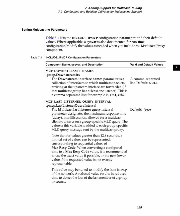
7 Adding Support for Multicast Routing7.2 Configuring and Building VxWorks for Multicasting Support
129
7
Setting Multicasting Parameters
Table 7-1 lists the INCLUDE_IPMCP configuration parameters and their default values. Where applicable, a sysvar is also documented for run-time configuration.Modify the values as needed when you include the Mutlicast Proxy component.
Table 7-1 INCLUDE_IPMCP Configuration Parameters
Component Name, sysvar, and Description Valid and Default Values
MCP_DOWNSTREAM_IFNAMESipmcp.DownstreamIfs
The Downstream interface names parameter is a collection of interfaces to which multicast packets arriving at the upstream inteface are forwarded (if that multicast group has at least one listener). This is a comma-separated list; for example is, eth1, eth2.
A comma-separated list. Default: NULL
MCP_LAST_LISTERNER_QUERY_INTERVALipmcp.LastListenerQueryInterval
The Multicast last listener query interval parameter designates the maximum response time (delay), in milliseconds, allowed for a multicast client to answer on a group-specific MLD query. The value of this variable is added to each group-specific MLD query message sent by the multicast proxy.
Note that for values greater than 12.8 seconds, a limited set of values can be represented, corresponding to sequential values of Max Resp Code. When converting a configured time to a Max Resp Code value, it is recommended to use the exact value if possible, or the next lower value if the requested value is not exactly representable.
This value may be tuned to modify the leave latency of the network. A reduced value results in reduced time to detect the loss of the last member of a group or source.
Default: "1000"
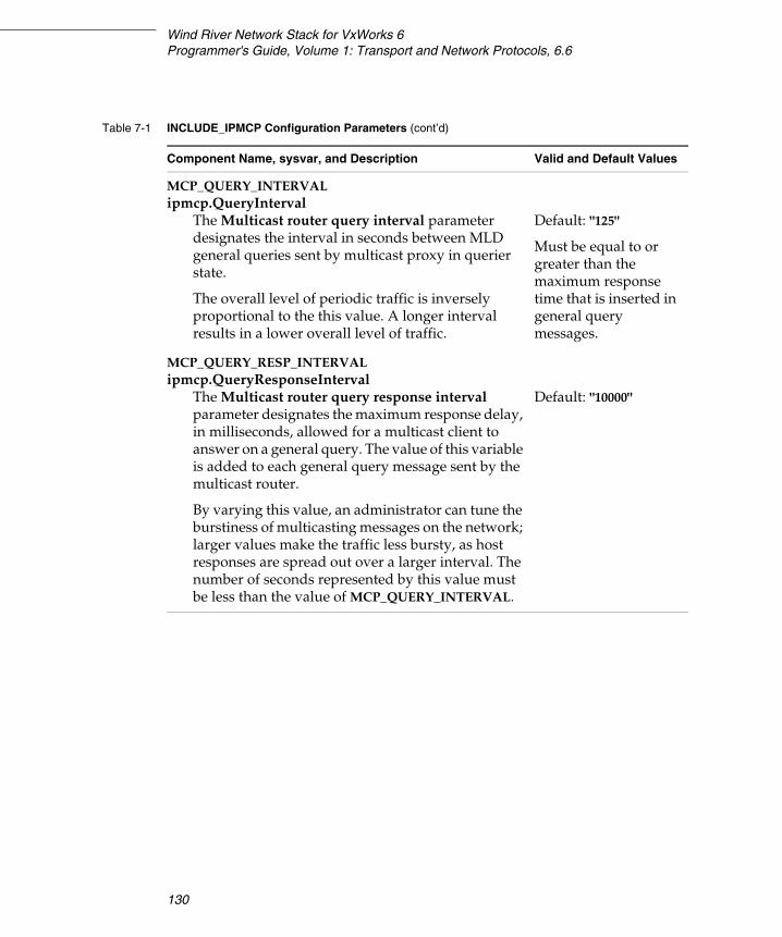
Wind River Network Stack for VxWorks 6Programmer's Guide, Volume 1: Transport and Network Protocols, 6.6
130
MCP_QUERY_INTERVALipmcp.QueryInterval
The Multicast router query interval parameter designates the interval in seconds between MLD general queries sent by multicast proxy in querier state.
The overall level of periodic traffic is inversely proportional to the this value. A longer interval results in a lower overall level of traffic.
Default: "125"
Must be equal to or greater than the maximum response time that is inserted in general query messages.
MCP_QUERY_RESP_INTERVALipmcp.QueryResponseInterval
The Multicast router query response interval parameter designates the maximum response delay, in milliseconds, allowed for a multicast client to answer on a general query. The value of this variable is added to each general query message sent by the multicast router.
By varying this value, an administrator can tune the burstiness of multicasting messages on the network; larger values make the traffic less bursty, as host responses are spread out over a larger interval. The number of seconds represented by this value must be less than the value of MCP_QUERY_INTERVAL.
Default: "10000"
Table 7-1 INCLUDE_IPMCP Configuration Parameters (cont’d)
Component Name, sysvar, and Description Valid and Default Values
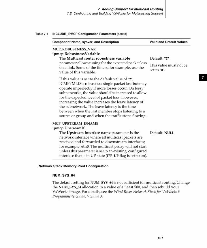
7 Adding Support for Multicast Routing7.2 Configuring and Building VxWorks for Multicasting Support
131
7
Network Stack Memory Pool Configuration
NUM_SYS_64
The default setting for NUM_SYS_64 is not sufficient for multicast routing. Change the NUM_SYS_64 allocation to a value of at least 500, and then rebuild your VxWorks image. For details, see the Wind River Network Stack for VxWorks 6 Programmer’s Guide, Volume 3.
MCP_ROBUSTNESS_VARipmcp.RobustnessVariable
The Multicast router robustness variable parameter allows tuning for the expected packet loss on a link. Some of the timers, for example, use the value of this variable.
If this value is set to the default value of "2", IGMP/MLD is robust to a single packet loss but may operate imperfectly if more losses occur. On lossy subnetworks, the value should be increased to allow for the expected level of packet loss. However, increasing the value increases the leave latency of the subnetwork. The leave latency is the time between when the last member stops listening to a source or group and when the traffic stops flowing.
Default: "2"
This value must not be set to "0".
MCP_UPSTREAM_IFNAMEipmcp.UpstreamIf
The Upstream interface name parameter is the network interface where all multicast packets are received and forwarded to downstream interfaces; for example, eth0. The multicast proxy will not start unless this parameter is set to an existing, configured interface that is in UP state (IFF_UP flag is set to on).
Default: NULL
Table 7-1 INCLUDE_IPMCP Configuration Parameters (cont’d)
Component Name, sysvar, and Description Valid and Default Values

Wind River Network Stack for VxWorks 6Programmer's Guide, Volume 1: Transport and Network Protocols, 6.6
132
7.3 Starting and Stopping the Router
Multicast routing requires a multicast daemon to work (in contrast to unicast routing, which can be used without a routing daemon). Wind River multicasting consists of a single daemon process called ipmcp, which has a management interface through which it can be started, stopped and (re)configured.
7.3.1 Running the Multicasting Router Daemon
To start, reconfigure, and stop the multicasting daemon you can use either the ipd shell command or call API routines.
Using the Shell
To start the daemon with ipd, run:
> ipd start ipmcp
To stop the daemon with ipd, run:
> ipd kil ipmcp
To use ipd to reread the configuration values listed in Setting Multicasting Parameters, p.129, run:
> ipd reconfigure ipmcp
ipd returns 0 on success, non-zero on error.
Using API Routines
To programmatically start the daemon, call this routine:
IP_PUBLIC Ip_erripcom_ipd_start(const char *name);
To programmatically stop the daemon, call this routine:
IP_PUBLIC Ip_erripcom_ipd_kill(const char *name);
To programmatically reconfigure the daemon, call this routine:
NOTE: If you build the stack without the multicast forwarding engine (which will make the stack smaller), the stack must be rebuilt with multicast routing to enable it. For details, see 7.2 Configuring and Building VxWorks for Multicasting Support, p.126.

7 Adding Support for Multicast Routing7.3 Starting and Stopping the Router
133
7
IP_PUBLIC Ip_erripcom_ipd_reconfigure(const char *name);
7.3.2 Getting Statistics
The multicast router daemon has a shell command, mcastproxy, which is used to get statistics from it. To use this command, configure VxWorks with INCLUDE_IPMCAST_PROXY_CMD, as described in 7.2.2 Configuring VxWorks with Multicasting, p.127.
mcastproxy
Name
mcastproxy – display the current status of the multicasting daemon
Synopsis
mcastproxy [-4|-6] <-i|-j|-r>
Description
This command displays a list of active multicast groups for each interface available. The MLD daemon shows the MLD state per interface, for example, QUERIER or NON QUERIER. The default, with no options, is to show both the IPv4 and IPv6 status.
The mcastproxy options are as follows:
-4 Show IPv4 only.
-6 Show IPv6 only.
-i Show interface statistics.
-j Show groups joined by clients.
-r Show route statistics.
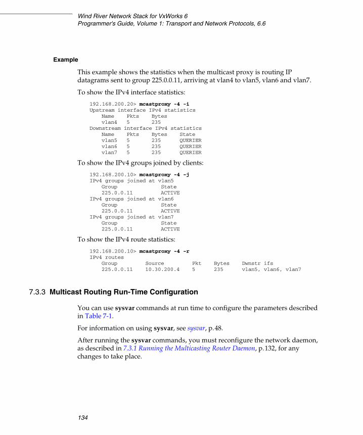
Wind River Network Stack for VxWorks 6Programmer's Guide, Volume 1: Transport and Network Protocols, 6.6
134
Example
This example shows the statistics when the multicast proxy is routing IP datagrams sent to group 225.0.0.11, arriving at vlan4 to vlan5, vlan6 and vlan7.
To show the IPv4 interface statistics:
192.168.200.20> mcastproxy -4 -i Upstream interface IPv4 statistics
Name Pkts Bytesvlan4 5 235
Downstream interface IPv4 statisticsName Pkts Bytes Statevlan5 5 235 QUERIERvlan6 5 235 QUERIERvlan7 5 235 QUERIER
To show the IPv4 groups joined by clients:
192.168.200.10> mcastproxy -4 -j IPv4 groups joined at vlan5
Group State225.0.0.11 ACTIVE
IPv4 groups joined at vlan6Group State225.0.0.11 ACTIVE
IPv4 groups joined at vlan7Group State225.0.0.11 ACTIVE
To show the IPv4 route statistics:
192.168.200.10> mcastproxy -4 -r IPv4 routes
Group Source Pkt Bytes Dwnstr ifs225.0.0.11 10.30.200.4 5 235 vlan5, vlan6, vlan7
7.3.3 Multicast Routing Run-Time Configuration
You can use sysvar commands at run time to configure the parameters described in Table 7-1.
For information on using sysvar, see sysvar, p.48.
After running the sysvar commands, you must reconfigure the network daemon, as described in 7.3.1 Running the Multicasting Router Daemon, p.132, for any changes to take place.
7 Adding Support for Multicast Routing7.4 Joining and Leaving Host Groups
135
7
7.3.4 Changing the Protocol Versions
INCLUDE_IPMCP_USE_IGMP is required to get support for the router end of IGMPv1,IGMPv2, and IGMPv3. INCLUDE_IPMCP_USE_MLD is required to get support for the router end of MLDv1 and MLDv2. The default is to use the latest versions of these protocols. To use an older procol version, run the following command through the sysvar:
ipmcp.igmp.CompatibilityMode
Valid values are 1, 2 and 3. The default is 3.
CompatibilityMode is the highest protocol version that the daemon will use.
Similarly for MLD, run the following command through sysvar:
ipmcp.mld.CompatibilityMode
Valid values are 1 and 2. The default is 2.
The INCLUDE_IPCOM_SYSVAR_CMD must be defined in order to access the sysvar shell command.
For more information on using sysvar with multicasting, see 7.3.3 Multicast Routing Run-Time Configuration, p.134.
7.4 Joining and Leaving Host Groups
IP multicasting transmits IP datagrams to host groups, which are sets of zero or more hosts identified by a single IP destination address. The multicast datagram is delivered to all members of its destination host group. Hosts join and leave multicast groups using a series of setsockopt( ) calls. Membership is dynamic, meaning that hosts can:
■ join and leave groups at any time
■ be a member of more than one group at a time
A host need not be a member of a group to send datagrams to it.
NOTE: An administrator must ensure that all multicast routers on a link are using the same version of the protocol.
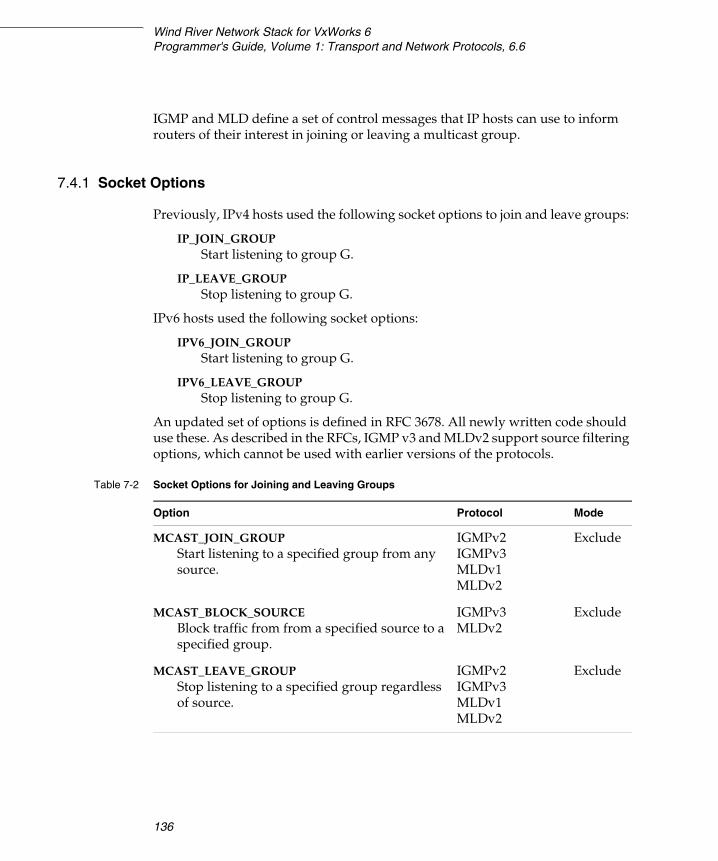
Wind River Network Stack for VxWorks 6Programmer's Guide, Volume 1: Transport and Network Protocols, 6.6
136
IGMP and MLD define a set of control messages that IP hosts can use to inform routers of their interest in joining or leaving a multicast group.
7.4.1 Socket Options
Previously, IPv4 hosts used the following socket options to join and leave groups:
IP_JOIN_GROUP Start listening to group G.
IP_LEAVE_GROUP Stop listening to group G.
IPv6 hosts used the following socket options:
IPV6_JOIN_GROUP Start listening to group G.
IPV6_LEAVE_GROUP Stop listening to group G.
An updated set of options is defined in RFC 3678. All newly written code should use these. As described in the RFCs, IGMP v3 and MLDv2 support source filtering options, which cannot be used with earlier versions of the protocols.
Table 7-2 Socket Options for Joining and Leaving Groups
Option Protocol Mode
MCAST_JOIN_GROUPStart listening to a specified group from any source.
IGMPv2IGMPv3MLDv1MLDv2
Exclude
MCAST_BLOCK_SOURCEBlock traffic from from a specified source to a specified group.
IGMPv3MLDv2
Exclude
MCAST_LEAVE_GROUPStop listening to a specified group regardless of source.
IGMPv2IGMPv3MLDv1MLDv2
Exclude
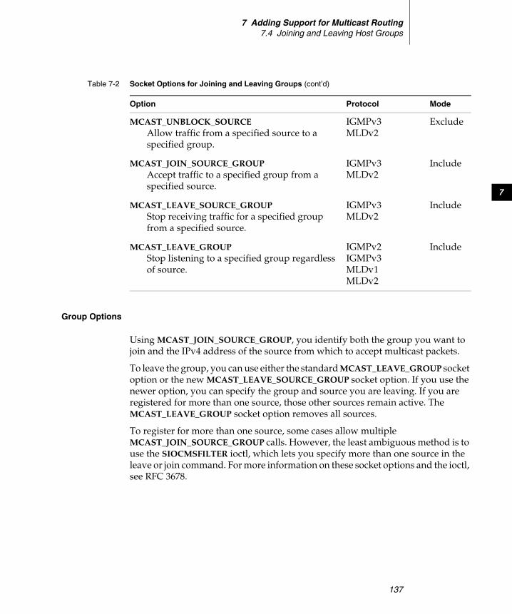
7 Adding Support for Multicast Routing7.4 Joining and Leaving Host Groups
137
7
Group Options
Using MCAST_JOIN_SOURCE_GROUP, you identify both the group you want to join and the IPv4 address of the source from which to accept multicast packets.
To leave the group, you can use either the standard MCAST_LEAVE_GROUP socket option or the new MCAST_LEAVE_SOURCE_GROUP socket option. If you use the newer option, you can specify the group and source you are leaving. If you are registered for more than one source, those other sources remain active. The MCAST_LEAVE_GROUP socket option removes all sources.
To register for more than one source, some cases allow multiple MCAST_JOIN_SOURCE_GROUP calls. However, the least ambiguous method is to use the SIOCMSFILTER ioctl, which lets you specify more than one source in the leave or join command. For more information on these socket options and the ioctl, see RFC 3678.
MCAST_UNBLOCK_SOURCEAllow traffic from a specified source to a specified group.
IGMPv3 MLDv2
Exclude
MCAST_JOIN_SOURCE_GROUPAccept traffic to a specified group from a specified source.
IGMPv3MLDv2
Include
MCAST_LEAVE_SOURCE_GROUPStop receiving traffic for a specified group from a specified source.
IGMPv3MLDv2
Include
MCAST_LEAVE_GROUPStop listening to a specified group regardless of source.
IGMPv2IGMPv3MLDv1MLDv2
Include
Table 7-2 Socket Options for Joining and Leaving Groups (cont’d)
Option Protocol Mode

Wind River Network Stack for VxWorks 6Programmer's Guide, Volume 1: Transport and Network Protocols, 6.6
138
Blocking Options
Using the option MCAST_BLOCK_SOURCE, you identify both the group you want to join and the IPv4 address of a source from which you will not accept multicast packets.
To unblock that source, use MCAST_UNBLOCK_SOURCE. To block more than one source, some circumstances allow multiple MCAST_BLOCK_SOURCE calls. However, the least ambiguous method is to use the SIOCMSFILTER ioctl, which lets you specify more than one source in the command.
7.4.2 Membership Reports for IGMPv1, IGMPv2, and MLDv1
The multicasting daemon keeps a compatibility mode per group record. To switch gracefully between versions of IGMP or MLD, it uses a host present timer per group record, and only sends a message from a given version as long as the timer for that version is running. Every IGMP/MLD membership report for group G is translated internally to “exclude no source addresses on group G.
For leaving groups, the processing is identical to IGMP/MLD membership report, except that a leave group for group G is translated internally to “include no source addresses on group G. However, leave group messages are ignored for groups in the IGMPv1 compatibility state.
7.5 Sending Queries and Reports
Multicasting routers send IGMP or MLD host membership queries to host groups periodically to update the memberships present on a particular network. Hosts listen for these queries and send reports back. Routers listen for the reports. If, after a specified number of queries, a router does not receive any reports for a particular group, it stop forwarding multicasts for that group. Thus, in short:
■ The router task is both a sender of IGMP/MLD queries and a listener of IGMP/MLD reports.
■ The hosts are listeners of queries and senders of reports.
For example, if a router sends a query that says: “all hosts that listen to group G, report to me,” all hosts that listen to group G must respond with a report within a
7 Adding Support for Multicast Routing7.5 Sending Queries and Reports
139
7
time specified in the query (a common value is 10 seconds). Sending traffic does not require anything special from the host. Receiving a specific group will trigger at least two things:
1. The host sends a unsolicited report to any router that says: I'm starting to listen on group G now.
2. The host must also configure its network interface (such as a network card) so that it can receive traffic sent to group G. Network interfaces will not receive any multicast traffic that they have not been explicitly configured to receive.
7.5.1 Network Interfaces
The IGMP/MLD multicasting proxy acts as an IGMP or MLD router on one or more network interfaces. These interfaces are denoted as downstream interfaces. There can be any number of downstream interfaces.
The IGMP/MLD multicasting proxy must also have one interface on which it will act as an IGMP and/or MLD host. This interface is denoted as an upstream interface, where multicast packets are received and possibly forwarded to one or more of the downstream interfaces. The upstream interface is normally connected to some form of public WAN, like the Internet.
When started, the multicasting daemon scans through all available interfaces in the system. Each interface found that is up, running, and multicast-capable is activated by the daemon. As soon as each such interface is assigned with an IPv6 address of link local scope, the daemon takes the role of MLD querier on that link. It starts to periodically send general query messages.
Simultaneously, the daemon listens for messages on all active links, discarding those that are malformed or inappropriately addrsesed. The same applies to messages that originate from the daemon itself.
The IGMP/MLD multicasting proxy can be configured to use any of the following versions of the multicasting protocols:
■ IGMPv1■ IGMPv2■ IGMPv3■ MLDv1■ MLDv2
Normally the highest protocol version is used, since it can handle lower versions of the protocol. For more information, see 7.3.4 Changing the Protocol Versions, p.135 and Query States, p.141.
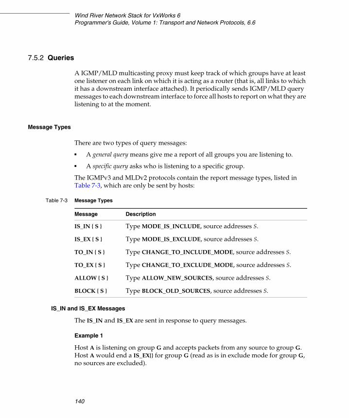
Wind River Network Stack for VxWorks 6Programmer's Guide, Volume 1: Transport and Network Protocols, 6.6
140
7.5.2 Queries
A IGMP/MLD multicasting proxy must keep track of which groups have at least one listener on each link on which it is acting as a router (that is, all links to which it has a downstream interface attached). It periodically sends IGMP/MLD query messages to each downstream interface to force all hosts to report on what they are listening to at the moment.
Message Types
There are two types of query messages:
■ A general query means give me a report of all groups you are listening to.
■ A specific query asks who is listening to a specific group.
The IGMPv3 and MLDv2 protocols contain the report message types, listed in Table 7-3, which are only be sent by hosts:
IS_IN and IS_EX Messages
The IS_IN and IS_EX are sent in response to query messages.
Example 1
Host A is listening on group G and accepts packets from any source to group G. Host A would end a IS_EX{} for group G (read as is in exclude mode for group G, no sources are excluded).
Table 7-3 Message Types
Message Description
IS_IN { S } Type MODE_IS_INCLUDE, source addresses S.
IS_EX { S } Type MODE_IS_EXCLUDE, source addresses S.
TO_IN { S } Type CHANGE_TO_INCLUDE_MODE, source addresses S.
TO_EX { S } Type CHANGE_TO_EXCLUDE_MODE, source addresses S.
ALLOW { S } Type ALLOW_NEW_SOURCES, source addresses S.
BLOCK { S } Type BLOCK_OLD_SOURCES, source addresses S.
7 Adding Support for Multicast Routing7.5 Sending Queries and Reports
141
7
Example 2
Host B is listening on group G and only accepts packets from source S to group G. Host B would send an IS_IN{S} for group G (meaning include mode for group G, include only source S).
Example 3
Host C is listening on group G and accepts packets any source but S1 and S2 to group G. Host C would end a IS_EX{S1,S2} for group G (read as is in exclude mode for group G, all sources are accepted except S1 and S2).
TO_IN, TO_EX, ALLOW, and BLOCK Messages
The TO_IN, TO_EX, ALLOW, and BLOCK messages are sent when a node makes changes to its group membership(s). For example, suppose host A wants to start to listen on group G accepting any source. Host A sends a TO_EX{}. Host A then decides to block traffic from sources S1, S2 and S3 on group G. Host A sends a BLOCK{S1,S2,S3}. Finally, host A wants to receive traffic from S2 again. Host A sends an ALLOW{S2}.
Query States
As mentioned, the IGMP or MLD query message is sent from IGMP/MLD routers only. Receiving a query means that there is another multicast router on the link. However, only one multicast router is allowed to be querier on the link.
To handle this situation, the proxy checks the source address of the MLD query. If the source address is numerically higher than the daemon’s own interface address, it enters the non-querier state on this interface.
The other querier present timer is activated, as described in Table 7-4.
NOTE: The option to block or allow traffic to a group from a specific source was not possible in IGMPv1, IPGMPv2 and MLDv1.
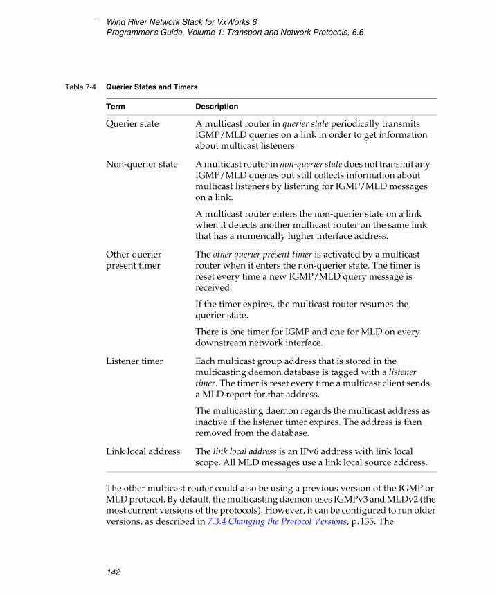
Wind River Network Stack for VxWorks 6Programmer's Guide, Volume 1: Transport and Network Protocols, 6.6
142
The other multicast router could also be using a previous version of the IGMP or MLD protocol. By default, the multicasting daemon uses IGMPv3 and MLDv2 (the most current versions of the protocols). However, it can be configured to run older versions, as described in 7.3.4 Changing the Protocol Versions, p.135. The
Table 7-4 Querier States and Timers
Term Description
Querier state A multicast router in querier state periodically transmits IGMP/MLD queries on a link in order to get information about multicast listeners.
Non-querier state A multicast router in non-querier state does not transmit any IGMP/MLD queries but still collects information about multicast listeners by listening for IGMP/MLD messages on a link.
A multicast router enters the non-querier state on a link when it detects another multicast router on the same link that has a numerically higher interface address.
Other querier present timer
The other querier present timer is activated by a multicast router when it enters the non-querier state. The timer is reset every time a new IGMP/MLD query message is received.
If the timer expires, the multicast router resumes the querier state.
There is one timer for IGMP and one for MLD on every downstream network interface.
Listener timer Each multicast group address that is stored in the multicasting daemon database is tagged with a listener timer. The timer is reset every time a multicast client sends a MLD report for that address.
The multicasting daemon regards the multicast address as inactive if the listener timer expires. The address is then removed from the database.
Link local address The link local address is an IPv6 address with link local scope. All MLD messages use a link local source address.
7 Adding Support for Multicast Routing7.5 Sending Queries and Reports
143
7
administrator must make sure that all multicast routers on a specific link use the same version.
7.5.3 Using Sockets
Multicasting is a feature of the IP layer, but to access this routine, an application uses a UDP socket. To open a socket, use socket( ).
First Parameter
The first parameter specifies the address family as IPv4 or IPv6, and is set to either:
■ AF_INET for IPv4
■ AF_INET6 for IPv6
Second Parameter
The second parameter specifies the type of socket, and can be set to either:
■ SOCK_DGRAM (for UDP traffic)
■ SOCK_RAW (protocol determined by the third argument)
Third Parameter
The third parameter is the IP protocol to use. It can be set to 0 if the second argument is SOCK_DGRAM, in which case the stack selects the default datagram protocol, which is UDP for the AF_INET and AF_INET6 domains. Otherwise, the third parameter should be one of the protocols defined by the IPPROTO_XXX constants. Typically, this parameter is one of the following:
■ IPPROTO_IGMP for IGMP ■ IPPROTO_ICMPV6 for MLD
MLD is just a subset of the ICMPv6 protocol. IGMP is a separate protocol from ICMP. IGMP has protocol number of 2 and ICMP has protocol number of 1.
Binding
To tell the stack which multicast groups a node wants to receive, an application can use either setsockopt( ) or bind( ). The bind( ) routine is used to specify the address a packet must be sent to in order to match the specified socket. The most common usage is to bind to the ANY address:
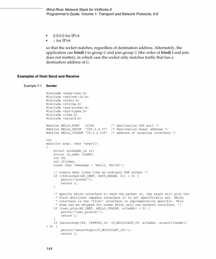
Wind River Network Stack for VxWorks 6Programmer's Guide, Volume 1: Transport and Network Protocols, 6.6
144
■ 0.0.0.0 for IPv4■ :: for IPv6
so that the socket matches, regardless of destination address. Alternately, the application can bind( ) to group G and join group G (the order of bind( ) and join does not matter), in which case the socket only matches traffic that has a destination address of G.
Examples of Host Send and Receive
Example 7-1 Sender
#include <arpa/inet.h>#include <netinet/in.h>#include <stdio.h>#include <string.h>#include <sys/socket.h>#include <sys/types.h>#include <time.h>#include <unistd.h>
#define HELLO_PORT 12345 /* destination UDP port */#define HELLO_GROUP "225.0.0.37" /* destination mcast address */#define HELLO_IFADDR "10.1.2.135" /* address of outgoing interface */
intmain(int argc, char *argv[]){ struct sockaddr_in to; struct in_addr ifaddr; int fd; int ifindex; const char *message = "Hello, World!";
/* create what looks like an ordinary UDP socket */ if ((fd=socket(AF_INET, SOCK_DGRAM, 0)) < 0) { perror("socket"); return 1; }
/* Specify which interface to send the packet to, the stack will pick the* first multicast capable interface it is not specifically set. Which * interface is the "first" interface is implementation specific. This * step can be skipped for nodes which only one network interface. */
if (inet_pton(AF_INET, HELLO_IFADDR, &ifaddr) < 0) { perror("inet_pton(G)"); return 1; } if (setsockopt(fd, IPPROTO_IP, IP_MULTICAST_IF, &ifaddr, sizeof(ifaddr)) < 0) { perror("setsockopt(IP_MULTICAST_IF)"); return 1;
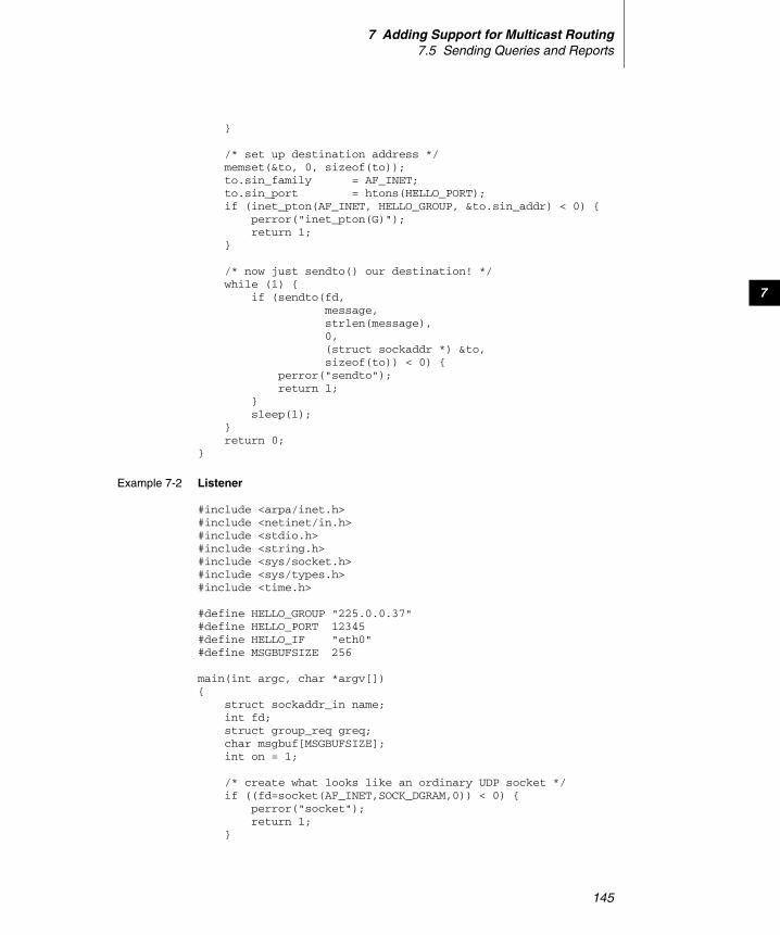
7 Adding Support for Multicast Routing7.5 Sending Queries and Reports
145
7
}
/* set up destination address */ memset(&to, 0, sizeof(to)); to.sin_family = AF_INET; to.sin_port = htons(HELLO_PORT); if (inet_pton(AF_INET, HELLO_GROUP, &to.sin_addr) < 0) { perror("inet_pton(G)"); return 1; }
/* now just sendto() our destination! */ while (1) { if (sendto(fd, message, strlen(message), 0, (struct sockaddr *) &to, sizeof(to)) < 0) { perror("sendto"); return 1; } sleep(1); } return 0;}
Example 7-2 Listener
#include <arpa/inet.h>#include <netinet/in.h>#include <stdio.h>#include <string.h>#include <sys/socket.h>#include <sys/types.h>#include <time.h>
#define HELLO_GROUP "225.0.0.37"#define HELLO_PORT 12345#define HELLO_IF "eth0"#define MSGBUFSIZE 256
main(int argc, char *argv[]){ struct sockaddr_in name; int fd; struct group_req greq; char msgbuf[MSGBUFSIZE]; int on = 1;
/* create what looks like an ordinary UDP socket */ if ((fd=socket(AF_INET,SOCK_DGRAM,0)) < 0) { perror("socket"); return 1; }
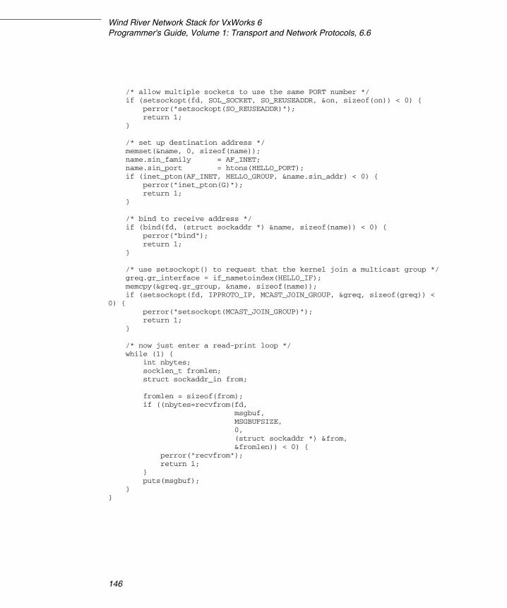
Wind River Network Stack for VxWorks 6Programmer's Guide, Volume 1: Transport and Network Protocols, 6.6
146
/* allow multiple sockets to use the same PORT number */ if (setsockopt(fd, SOL_SOCKET, SO_REUSEADDR, &on, sizeof(on)) < 0) { perror("setsockopt(SO_REUSEADDR)"); return 1; }
/* set up destination address */ memset(&name, 0, sizeof(name)); name.sin_family = AF_INET; name.sin_port = htons(HELLO_PORT); if (inet_pton(AF_INET, HELLO_GROUP, &name.sin_addr) < 0) { perror("inet_pton(G)"); return 1; }
/* bind to receive address */ if (bind(fd, (struct sockaddr *) &name, sizeof(name)) < 0) { perror("bind"); return 1; }
/* use setsockopt() to request that the kernel join a multicast group */ greq.gr_interface = if_nametoindex(HELLO_IF); memcpy(&greq.gr_group, &name, sizeof(name)); if (setsockopt(fd, IPPROTO_IP, MCAST_JOIN_GROUP, &greq, sizeof(greq)) < 0) { perror("setsockopt(MCAST_JOIN_GROUP)"); return 1; }
/* now just enter a read-print loop */ while (1) { int nbytes; socklen_t fromlen; struct sockaddr_in from;
fromlen = sizeof(from); if ((nbytes=recvfrom(fd, msgbuf, MSGBUFSIZE, 0, (struct sockaddr *) &from, &fromlen)) < 0) { perror("recvfrom"); return 1; } puts(msgbuf); }}
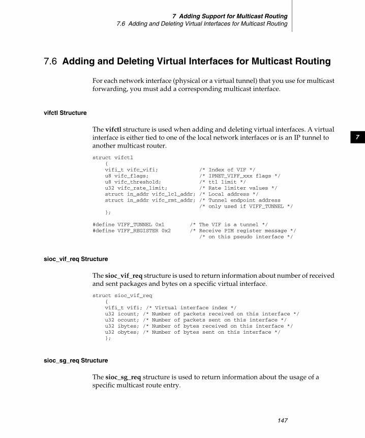
7 Adding Support for Multicast Routing7.6 Adding and Deleting Virtual Interfaces for Multicast Routing
147
7
7.6 Adding and Deleting Virtual Interfaces for Multicast Routing
For each network interface (physical or a virtual tunnel) that you use for multicast forwarding, you must add a corresponding multicast interface.
vifctl Structure
The vifctl structure is used when adding and deleting virtual interfaces. A virtual interface is either tied to one of the local network interfaces or is an IP tunnel to another multicast router.
struct vifctl{vifi_t vifc_vifi; /* Index of VIF */u8 vifc_flags; /* IPNET_VIFF_xxx flags */u8 vifc_threshold; /* ttl limit */u32 vifc_rate_limit; /* Rate limiter values */struct in_addr vifc_lcl_addr; /* Local address */struct in_addr vifc_rmt_addr; /* Tunnel endpoint address
/* only used if VIFF_TUNNEL */};
#define VIFF_TUNNEL 0x1 /* The VIF is a tunnel */#define VIFF_REGISTER 0x2 /* Receive PIM register message */
/* on this pseudo interface */
sioc_vif_req Structure
The sioc_vif_req structure is used to return information about number of received and sent packages and bytes on a specific virtual interface.
struct sioc_vif_req{vifi_t vifi; /* Virtual interface index */u32 icount; /* Number of packets received on this interface */u32 ocount; /* Number of packets sent on this interface */u32 ibytes; /* Number of bytes received on this interface */u32 obytes; /* Number of bytes sent on this interface */};
sioc_sg_req Structure
The sioc_sg_req structure is used to return information about the usage of a specific multicast route entry.
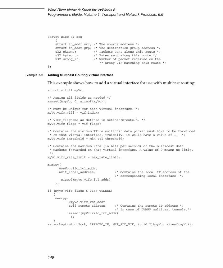
Wind River Network Stack for VxWorks 6Programmer's Guide, Volume 1: Transport and Network Protocols, 6.6
148
struct sioc_sg_req{struct in_addr src; /* The source address */struct in_addr grp; /* The destination group address */u32 pktcnt; /* Packets sent along this route */u32 bytecnt; /* Bytes sent along this route */u32 wrong_if; /* Number of packet received on the
/* wrong VIF matching this route */};
Example 7-3 Adding Multicast Routing Virtual Interface
This example shows how to add a virtual interface for use with multicast routing:
struct vifctl myVc;
/* Assign all fields as needed */ memset(&myVc, 0, sizeof(myVc));
/* Must be unique for each virtual interface. */myVc.vifc_vifi = vif_index;
/* VIFF_flagname as defined in netinet/mroute.h. */myVc.vifc_flags = vif_flags;
/* Contains the minimum TTL a multicast data packet must have to be forwarded* on that virtual interface. Typically, it would have a value of 1. */myVc.vifc_threshold = min_ttl_threshold;
/* Contains the maximum rate (in bits per second) of the multicast data * packets forwarded on that virtual interface. A value of 0 means no limit.*/myVc.vifc_rate_limit = max_rate_limit;
memcpy(&myVc.vifc_lcl_addr, &vif_local_address, /* Contains the local IP address of the
/* corresponding local interface. */sizeof(myVc.vifc_lcl_addr)
);
if (myVc.vifc_flags & VIFF_TUNNEL){ memcpy(
&myVc.vifc_rmt_addr, &vif_remote_address, /* Contains the remote IP address */
/* in case of DVMRP multicast tunnels.*/sizeof(myVc.vifc_rmt_addr));
}setsockopt(mRoutSock, IPPROTO_IP, MRT_ADD_VIF, (void *)&myVc, sizeof(myVc));
7 Adding Support for Multicast Routing7.6 Adding and Deleting Virtual Interfaces for Multicast Routing
149
7
Example 7-4 Deleting Virtual Multicast Routing Interfaces
This example shows how to delete a multicast interface:
vifi_t myViIfIndex = vif_index; setsockopt(mRoutSock, IPPROTO_IP, MRT_DEL_VIF, (void *)&myViIfIndex, sizeof(myViIfIndex));
Opening a Multicast Socket for Receiving Upcalls
After multicast forwarding is enabled and the multicast virtual interfaces are added, the kernel can deliver upcalls on the multicast routing socket that you opened earlier and for which you have set the options MRT_INIT. The upcalls use a struct igmpmsg header (see <netinet/ip_mroute.h>) with the im_mbz field set to zero. Note that this header follows the structure of struct ip with the ip_p protocol field set to zero.
The upcall header contains im_msgtype field with the type of the upcall IGMPMSG_type. The values of the rest of the signal header fields and the body of the signal message depend on the particular signal type.
If the upcall message type is IGMPMSG_NOCACHE, a multicast packet has reached the multicast router, but the router has no forwarding state for that packet. Typically, the message is a signal for the multicast routing user-level process to install the appropriate multicast forwarding cache (MFC) entry in the kernel.
mfcctl Structure
The mfcctl structure describes the virtual interfaces to which a multicast should be forwarded. It is always a one-to-one mapping in the incoming and outgoing interfaces for unicast packages, but that is not the case with multicast. One incoming packet can be forward to up to MAXVIFS number of virtual interfaces.
struct mfcctl{struct in_addr mfcc_orgin; /* The sender of the multicast packet */struct in_addr mfcc_mcastgrp; /* The group the packet is sent to */vifi_t mfcc_parent; /* The VIF that the packet is */d
/* expected to arrive on */u8 mfcc_ttls[MAXVIFS]; /* mfcc_ttls[VIF id] != 0 if packet */
/* sent along this route should *//* be forwarded to that VIF */
};
Wind River Network Stack for VxWorks 6Programmer's Guide, Volume 1: Transport and Network Protocols, 6.6
150
Example 7-5 Adding an Entry to an MFC
To add an entry to an MFC:
struct mfcctl mc; memset(&mc, 0, sizeof(mc));memcpy(&mc.mfcc_origin, &source_addr, sizeof(mc.mfcc_origin));memcpy(&mc.mfcc_mcastgrp, &group_addr, sizeof(mc.mfcc_mcastgrp));mc.mfcc_parent = iif_index; for (i = 0; i < maxvifs; i++)
{mc.mfcc_ttls[i] = oifs_ttl[i]; }
setsockopt(mRoutSock, IPPROTO_IP, MRT_ADD_MFC, (void *)&mc, sizeof(mc));
where:
source_addr and group_addr are the source and group address of the multicast packet (as set in the upcall message).
iif_index is the virtual interface index of the multicast interface the multicast packets for this specific source and group address should be received on.
oifsv_ttl[ ] is the minimum TTL (per interface) a multicast packet should have to be forwarded on an outgoing interface. If the TTL value is zero, the corresponding interface is not included in the set of outgoing interfaces.
7.7 Using PIM Hooks
The Wind River Network Stack does not include a PIM implementation. If you write or port a PIM implementation, you can access it in the standard way described below.
Protocol Independent Multicast (PIM)
PIM is the common name for two multicast routing protocols: Protocol Independent Multicast - Sparse Mode (PIM-SM) and Protocol Independent Multicast - Dense Mode (PIM-DM).
PIM-SM is a multicast routing protocol that can use the underlying unicast routing information base or a separate multicast-capable routing information base. It
7 Adding Support for Multicast Routing7.7 Using PIM Hooks
151
7
builds unidirectional shared trees rooted at a rendezvous point (RP) per group and optionally creates shortest-path trees per source.
PIM-DM is a multicast routing protocol that uses the underlying unicast routing information base to flood multicast datagrams to all multicast routers. Prune messages are used to prevent future datagrams from propagating to routers with no group membership information.
Both PIM-SM and PIM-DM are fairly complex protocols, although PIM-SM is much more complex than PIM-DM. To enable PIM-SM or PIM-DM multicast routing in a router, you must enable multicast routing and PIM processing in the kernel and run a PIM-SM- or PIM-DM-capable application.
Using a Socket Interface to Enable and Access PIM Functionality
After opening a multicast routing socket and enabling multicast forwarding, use one of the following socket options to enable or disable PIM processing in the kernel:
int version = 1; setsockopt( mRoutSock, IPPROTO_IP, MRT_INIT, (void *)&version,sizeof(version) );
After you have enabled PIM processing, add the multicast-capable interfaces (see Example 7-3). In case of PIM-SM, you must also add the PIM-Register virtual interface. To do this, use the following options:
struct vifctl vc; memset(&vc, 0, sizeof(vc)); /* Assign all vifctl fields as needed. */ ... if (is_pim_register_vif)
{vc.vifc_flags |= VIFF_REGISTER;
}setsockopt(mRoutSock, IPPROTO_IP, MRT_ADD_VIF, (void *)&vc, sizeof(vc));
To send or receive PIM packets, first you must open a raw socket (see the socket( ) reference entry), with protocol value of IPPROTO_PIM:
int pim_s4; pim_s4 = socket(AF_INET, SOCK_RAW, IPPROTO_PIM);
After opening the raw socket for PIM, send or receive PIM packets on that socket by calling sendto( ), sendmsg( ), recvfrom( ), or recvmsg( ).
NOTE: There is no limit on the number of source addresses per group or per socket.

Wind River Network Stack for VxWorks 6Programmer's Guide, Volume 1: Transport and Network Protocols, 6.6
152
153
8Wind River Mobile IP: Overview
8.1 Introduction 153
8.2 Mobile IP Technical Overview 154
8.1 Introduction
The Wind River network stack contains implementations of a mobile node, home agent, and foreign agent as specified in RFC 3344, IP Mobility Support for IPv4, and it contains an implementation of a mobile node for IPv6, as specified in RFC 3775 (Mobility Support in IPv6). The implementations of the individual components are described in chapters following this overview.
Mobility support allows a node that is configured for mobility (a mobile node) to move from one network link to another without losing its connection to another node and without changing its accessibility to other nodes in the network. A mobile node is always accessible through its home agent, a router on the mobile node’s home link that knows where the mobile node is.
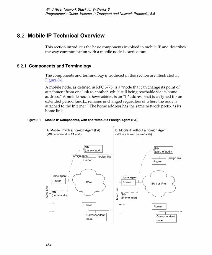
Wind River Network Stack for VxWorks 6Programmer's Guide, Volume 1: Transport and Network Protocols, 6.6
154
8.2 Mobile IP Technical Overview
This section introduces the basic components involved in mobile IP and describes the way communication with a mobile node is carried out.
8.2.1 Components and Terminology
The components and terminology introduced in this section are illustrated in Figure 8-1.
A mobile node, as defined in RFC 3775, is a “node that can change its point of attachment from one link to another, while still being reachable via its home address.” A mobile node’s home address is an “IP address that is assigned for an extended period [and]... remains unchanged regardless of where the node is attached to the Internet.” The home address has the same network prefix as its home link.
Figure 8-1 Mobile IP Components, with and without a Foreign Agent (FA)
...
...
...
IPv4
foreign link
MN(home addr)
Home agent
Router
Router
Correspondent node
hom
e lin
k
Router
...
...
...
...
IPv4 or IPv6
foreign link
Home agent
Router
Router
Correspondent node
hom
e lin
k
Router
...
MN(home addr)
MN(care-of addr)
MN(care-of addr)
Foreign agent
A. Mobile IP with a Foreign Agent (FA)(MN care-of-addr = FA addr)
B. Mobile IP without a Foreign Agent(MN has its own care-of-addr)
8 Wind River Mobile IP: Overview8.2 Mobile IP Technical Overview
155
8
A node that communicates with the mobile node is a correspondent node. When a mobile node leaves its home link and attaches to a different link, the link to which it attaches is a foreign link. When a mobile node attaches to a foreign link, it obtains a care-of address on the foreign link. The care-of address is an IP address used for communication between the mobile node and the mobile node’s home agent. The home agent is a router on the mobile node’s home link that supports mobile IP.
Mobile IP for IPv4 gives the mobile node the option of obtaining its care-of address from a foreign agent or of obtaining it by other means, for example through the Dynamic Host Configuration Protocol (DHCP). A foreign agent is a router on the mobile node’s foreign link that supports Mobile IP for IPv4. If the Mobile node obtains its care-of address from a foreign agent, the care-of address is the address of the foreign agent.
Mobile IP for IPv6 does not use a foreign agent. When an IPv6 mobile node is on a foreign link, it obtains its IP address through stateless autoconfiguration (RFC 2462) or through stateful (DHCPv6) configuration.
8.2.2 Communication with the Mobile Node
When a mobile node is on its home link, communication with a correspondent node is carried out in exactly the same way as it would be without mobile IP. When the mobile node is on a foreign link, the way communication is carried out can differ between mobile IP for IPv4 and mobile IP for IPv6.
Communication with the Mobile Node in IPv4
When a mobile IPv4 mobile node is on a foreign link, messages sent from the correspondent node to the mobile node always go to the mobile node’s home agent first and from there to the mobile node. The home agent tunnels the correspondent node’s message either to the mobile node’s foreign agent or directly to the mobile node. Messages from the mobile node to the correspondent node are either sent using reverse tunneling or are sent directly to the correspondent node. In Wind River’s mobile-IPv4 implementation, the type of communication used is determined by a static configuration parameter. Bidirectional tunneling, tunneling using a home agent in both directions, is illustrated in sections A and B of Figure 8-2. Tunneling one way and direct communication from mobile node to correspondent node is illustrated in section C of Figure 8-2.
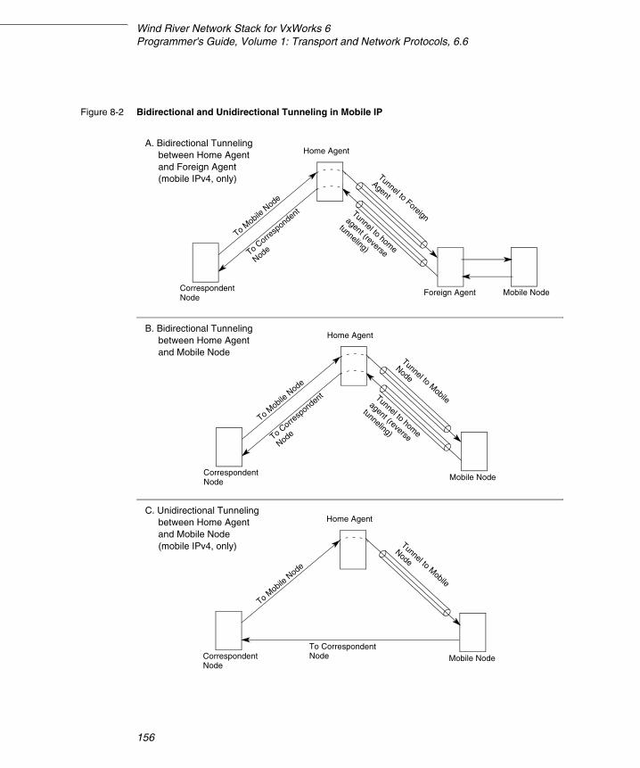
Wind River Network Stack for VxWorks 6Programmer's Guide, Volume 1: Transport and Network Protocols, 6.6
156
Figure 8-2 Bidirectional and Unidirectional Tunneling in Mobile IP
CorrespondentNode
Foreign Agent
Home Agent
To Mobile
Node
Tunnel to home
agent (reverse
tunneling)
Tunnel to Foreign
Agent
To Corre
spondent
Node
Mobile Node
CorrespondentNode
Home Agent
To Mobile
Node
Tunnel to home
agent (reverse
tunneling)
Tunnel to Mobile
Node
To Corre
spondent
Node
Mobile Node
CorrespondentNode
Home Agent
To Mobile
Node
Tunnel to Mobile
Node
To CorrespondentNode Mobile Node
A. Bidirectional Tunnelingbetween Home Agentand Foreign Agent(mobile IPv4, only)
B. Bidirectional Tunnelingbetween Home Agentand Mobile Node
C. Unidirectional Tunnelingbetween Home Agentand Mobile Node(mobile IPv4, only)

8 Wind River Mobile IP: Overview8.2 Mobile IP Technical Overview
157
8
Communication with the Mobile Node in IPv6
In Wind River’s implementation of mobile IPv6, when the mobile node is on a foreign link, all communication between the mobile node and a correspondent node uses bidirectional tunneling, as illustrated in section B of Figure 8-2. Direct communication between mobile node and correspondent node (route optimization) is described in RFC 3775, Mobility Support in IPv6, but is not supported in the current release.
Sequence of Steps in Establishing and Carrying out Mobile Communication
The basic steps in mobile IPv6 communication are:
1. The mobile node moves from its home link to a foreign link.
2. The mobile node obtains a temporary care-of address on the foreign link.
■ The care-of address is an IP address with the same network prefix as the foreign link.
■ In mobile IPv4, if the mobile node uses a foreign agent, the care-of address is the same as the foreign agent’s IP address. Otherwise, the address is a unicast address obtained either through DHCP or direct configuration.
■ In mobile IPv6, to obtain its care-of address, a mobile node can use IPv6 stateless or stateful (DHCP) auto-configuration.
3. The mobile node sets up communication with a home agent on its home link and registers its care-of address with the home agent.
■ IPsec is used for communication between the mobile node and the home agent.
■ The home agent can be the mobile node’s default router on its home link, or it can be another router on the link.
■ The router that serves as a home agent for the mobile node must have its own software for implementing a mobile IPv6 home agent.
4. The home agent binds its own MAC address to the mobile node’s home address.
This allows the home agent to capture packets sent to the mobile node and then tunnel the packets to the mobile node using the mobile node’s care-of address.
Wind River Network Stack for VxWorks 6Programmer's Guide, Volume 1: Transport and Network Protocols, 6.6
158
5. Communication between the mobile node and a correspondent node is carried out through either bidirectional tunneling (available in the implementations of both mobile IPv4 and mobile IPv6— Figure 8-2, sections A and B) or unidirectional tunneling (mobile IPv4, only—Figure 8-2, section C). As noted previously, direct communication between mobile node and correspondent node is provided for in RFC 3775 for mobile IPv6, but is not supported in the current release of Wind River Mobile IPv6.
6. If the mobile node moves to another foreign link, it obtains a new care-of address and registers it with its home agent. Communication is now carried out over the new care-of address.
7. When the mobile node returns to its home link, it de-registers its care-of address with the home agent.
159
9Wind River Mobile IPv4:
Mobile Node
9.1 Introduction 159
9.2 Mobile Node Features 160
9.3 Conformance to Standards 162
9.4 Build Component and Build Parameters 163
9.5 Including the Mobile Node in a Build 185
9.6 Shell Commands 185
9.7 Testing the Mobile Node 187
9.1 Introduction
This chapter describes the Wind River implementation of a mobile node for IPv4. For a general overview of Mobile IP see 8. Wind River Mobile IP: Overview.
Wind River Network Stack for VxWorks 6Programmer's Guide, Volume 1: Transport and Network Protocols, 6.6
160
9.2 Mobile Node Features
The Wind River mobile node for IPv4 implements RFC 3344, IP Mobility Support for IPv4. The following are features of the implementation that are not in RFC 3344 and whose implementation may need some explanation:
■ Low-latency handoffs in going from one foreign agent to another (see 9.2.1 Low-Latency Handoffs, p.160)
■ Integration with Internet Key Exchange (IKE) and IPsec (see 9.2.2 Integration with IPsec and IKE, p.161)
9.2.1 Low-Latency Handoffs
The Wind River mobile node implements the IETF Internet-Draft Low Latency Handoffs in Mobile IPv4, dated October, 2005, with an expiration date of April, 2006. The draft proposes three ways of reducing delays in registering a new care-of address when the mobile node moves from one foreign agent (the “old” foreign agent) to another foreign agent (the “new” foreign agent):
■ Pre-registration handoff
This approach allows the mobile node to communicate with a new foreign agent in order to obtain a new care-of address while it is still connected to the old foreign agent.
■ Post-registration handoff
This allows data to be delivered to the mobile node at a new foreign agent before the process of registering the mobile node’s new care-of address has completed. Data is delivered using bidirectional tunneling between the old and the new foreign agents.
■ Combined handoff
In this case, the pre-registration and post-registration handoffs are carried out in parallel.
The current implementation supports all three methods.
9 Wind River Mobile IPv4: Mobile Node9.2 Mobile Node Features
161
9
9.2.2 Integration with IPsec and IKE
The mobile node can be configured to run in either fa (foreign agent) mode, in which case it obtains it care-of address from a foreign agent, or in co (co-located) mode, in which case it obtains its care-of address without using a foreign agent (see Mobile node run mode in Table 9-2 in 9.4 Build Component and Build Parameters, p.163).
If the mobile node is configured to run in co-located mode, you can also configure it to use IPsec and IKE when communicating with its home agent. There are three configuration parameters for this:
■ IPSEC protected CoA only (MIPMN_IPSEC_PROTECTED)
This parameter allows you to apply Wind River IPsec security policies to care-of addresses.
■ IPIKE secure address only (MIPMN_IPIKE_SECURE)
You can use this parameter to specify that the mobile node only uses IKE tunnel inner address (TIAs) as care-of addresses. A TIA is an address that IKE dynamically allocates as part of the negotiation of security parameters.
■ IPIKE reconfiguration on movement (MIPMN_IPIKE_RECONFIGURE)
You can use this parameter to configure the mobile node so that whenever it moves and needs a new care-of address, it sends a reconfiguration request to Wind River IKE.
IPIKE Mobike On Movement (MIPMN_IPIKE_MOBIKE)
When this parameter is enabled, the mobile node uses MOBIKE (see RFC 4555, IKEv2 Mobility and Multihoming Protocol (MOBIKE)) to re-establish an encrypted channel previously created by IPIKE.
For more information on these parameters, see the entries for them in Table 9-2, Section 9.4 Build Component and Build Parameters, p.163.
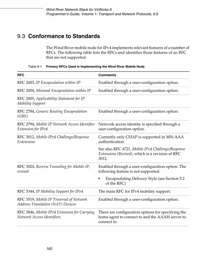
Wind River Network Stack for VxWorks 6Programmer's Guide, Volume 1: Transport and Network Protocols, 6.6
162
9.3 Conformance to Standards
The Wind River mobile node for IPv4 implements relevant features of a number of RFCs. The following table lists the RFCs and identifies those features of an RFC that are not supported.
Table 9-1 Primary RFCs Used in Implementing the Wind River Mobile Node
RFC Comments
RFC 2003, IP Encapsulation within IP Enabled through a user-configuration option.
RFC 2004, Minimal Encapsulation within IP Enabled through a user-configuration option.
RFC 2005, Applicability Statement for IP Mobility Support
RFC 2784, Generic Routing Encapsulation (GRE)
Enabled through a user-configuration option.
RFC 2794, Mobile IP Network Access Identifier Extension for IPv4
Network access identity is specified through a user-configuration option.
RFC 3012, Mobile IPv4 Challenge/Response Extensions
Currently only CHAP is supported in MN-AAA authentication.
See also RFC 4721, Mobile IPv4 Challenge/Response Extensions (Revised), which is a revision of RFC 3012.
RFC 3024, Reverse Tunneling for Mobile IP, revised
Enabled through a user-configuration option. The following feature is not supported:
■ Encapsulating Delivery Style (see Section 5.2 of the RFC)
RFC 3344, IP Mobility Support for IPv4 The main RFC for IPv4 mobility support.
RFC 3519, Mobile IP Traversal of Network Address Translation (NAT) Devices
Enabled through a user-configuration option.
RFC 3846, Mobile IPv4 Extension for Carrying Network Access Identifiers
There are configuration options for specifying the home agent to connect to and the AAAH server to connect to.
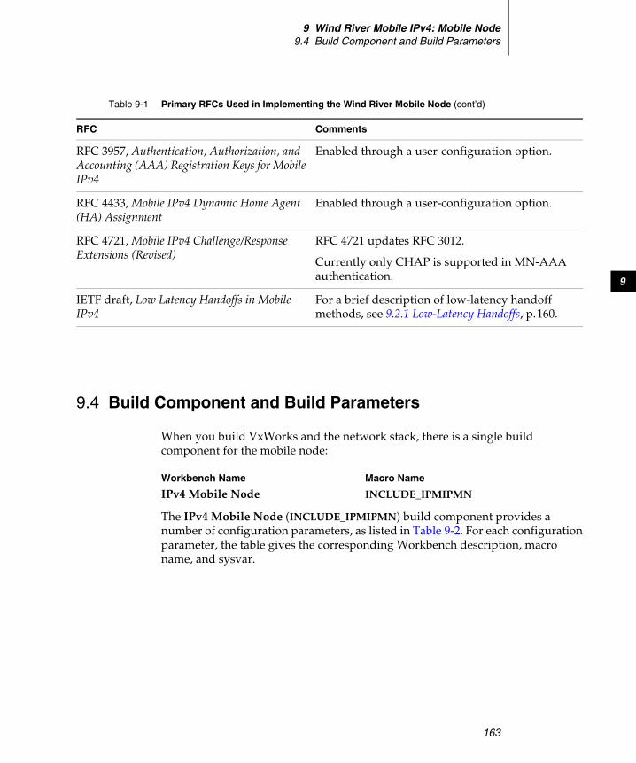
9 Wind River Mobile IPv4: Mobile Node9.4 Build Component and Build Parameters
163
9
9.4 Build Component and Build Parameters
When you build VxWorks and the network stack, there is a single build component for the mobile node:
The IPv4 Mobile Node (INCLUDE_IPMIPMN) build component provides a number of configuration parameters, as listed in Table 9-2. For each configuration parameter, the table gives the corresponding Workbench description, macro name, and sysvar.
RFC 3957, Authentication, Authorization, and Accounting (AAA) Registration Keys for Mobile IPv4
Enabled through a user-configuration option.
RFC 4433, Mobile IPv4 Dynamic Home Agent (HA) Assignment
Enabled through a user-configuration option.
RFC 4721, Mobile IPv4 Challenge/Response Extensions (Revised)
RFC 4721 updates RFC 3012.
Currently only CHAP is supported in MN-AAA authentication.
IETF draft, Low Latency Handoffs in Mobile IPv4
For a brief description of low-latency handoff methods, see 9.2.1 Low-Latency Handoffs, p.160.
Table 9-1 Primary RFCs Used in Implementing the Wind River Mobile Node (cont’d)
RFC Comments
Workbench Name Macro Name
IPv4 Mobile Node INCLUDE_IPMIPMN
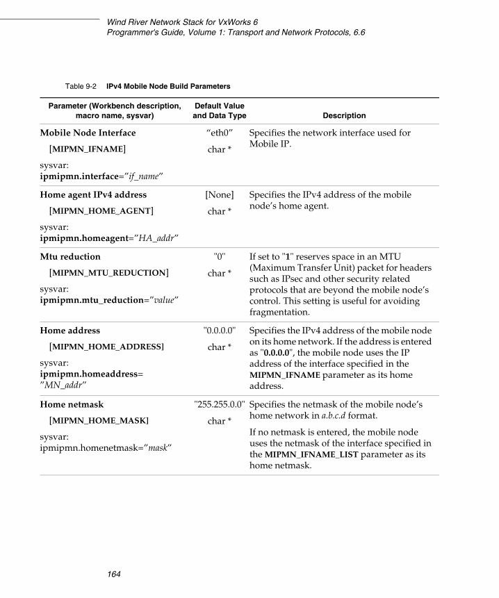
Wind River Network Stack for VxWorks 6Programmer's Guide, Volume 1: Transport and Network Protocols, 6.6
164
Table 9-2 IPv4 Mobile Node Build Parameters
Parameter (Workbench description, macro name, sysvar)
Default Value and Data Type Description
Mobile Node Interface
[MIPMN_IFNAME]
sysvar:ipmipmn.interface=”if_name”
“eth0”
char *
Specifies the network interface used for Mobile IP.
Home agent IPv4 address
[MIPMN_HOME_AGENT]
sysvar:ipmipmn.homeagent=”HA_addr”
[None]
char *
Specifies the IPv4 address of the mobile node’s home agent.
Mtu reduction
[MIPMN_MTU_REDUCTION]
sysvar:ipmipmn.mtu_reduction=”value”
"0"
char *
If set to "1" reserves space in an MTU (Maximum Transfer Unit) packet for headers such as IPsec and other security related protocols that are beyond the mobile node’s control. This setting is useful for avoiding fragmentation.
Home address
[MIPMN_HOME_ADDRESS]
sysvar:ipmipmn.homeaddress=”MN_addr”
"0.0.0.0"
char *
Specifies the IPv4 address of the mobile node on its home network. If the address is entered as "0.0.0.0", the mobile node uses the IP address of the interface specified in the MIPMN_IFNAME parameter as its home address.
Home netmask
[MIPMN_HOME_MASK]
sysvar:ipmipmn.homenetmask=”mask”
"255.255.0.0"
char *
Specifies the netmask of the mobile node’s home network in a.b.c.d format.
If no netmask is entered, the mobile node uses the netmask of the interface specified in the MIPMN_IFNAME_LIST parameter as its home netmask.
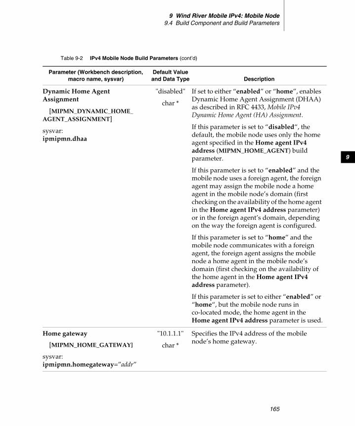
9 Wind River Mobile IPv4: Mobile Node9.4 Build Component and Build Parameters
165
9
Dynamic Home Agent Assignment
[MIPMN_DYNAMIC_HOME_AGENT_ASSIGNMENT]
sysvar:ipmipmn.dhaa
"disabled"
char *
If set to either “enabled” or “home”, enables Dynamic Home Agent Assignment (DHAA) as described in RFC 4433, Mobile IPv4 Dynamic Home Agent (HA) Assignment.
If this parameter is set to “disabled“, the default, the mobile node uses only the home agent specified in the Home agent IPv4 address (MIPMN_HOME_AGENT) build parameter.
If this parameter is set to “enabled” and the mobile node uses a foreign agent, the foreign agent may assign the mobile node a home agent in the mobile node’s domain (first checking on the availability of the home agent in the Home agent IPv4 address parameter) or in the foreign agent’s domain, depending on the way the foreign agent is configured.
If this parameter is set to “home” and the mobile node communicates with a foreign agent, the foreign agent assigns the mobile node a home agent in the mobile node’s domain (first checking on the availability of the home agent in the Home agent IPv4 address parameter).
If this parameter is set to either “enabled” or “home“, but the mobile node runs in co-located mode, the home agent in the Home agent IPv4 address parameter is used.
Home gateway
[MIPMN_HOME_GATEWAY]
sysvar:ipmipmn.homegateway=”addr”
"10.1.1.1"
char *
Specifies the IPv4 address of the mobile node’s home gateway.
Table 9-2 IPv4 Mobile Node Build Parameters (cont’d)
Parameter (Workbench description, macro name, sysvar)
Default Value and Data Type Description

Wind River Network Stack for VxWorks 6Programmer's Guide, Volume 1: Transport and Network Protocols, 6.6
166
Router solicitation address
[MIPMN_SOL_ADDRESS]
sysvar:ipmipmn.sol_address=”addr”
"224.0.0.11"
char *
Specifies the destination address of outgoing router solicitation messages from the mobile node.
If not set, or if set to “0.0.0.0” or an invalid address, no router solicitations are sent.
Default Home Agent Shared Secret
[MIPMN_HA_AUTH_SECRET]
sysvar:ipmipmn.haauthsecret=”secret”
“test0”
char *
Specifies the default shared secret to use in authentication with home agents. You can override the default shared secret and assign individual home agents their own shared secrets by setting all three of the following parameters:
■ Home Agent Security Association Secrets (MIPMN_HA_SPI_SECRET_LIST)
■ Home Agent Security Association Methods (MIPMN_HA_SPI_METHOD_LIST)
■ Home Agent Security Association Selection (MIPMN_HA_SA_ADDRESS_LIST)
Table 9-2 IPv4 Mobile Node Build Parameters (cont’d)
Parameter (Workbench description, macro name, sysvar)
Default Value and Data Type Description
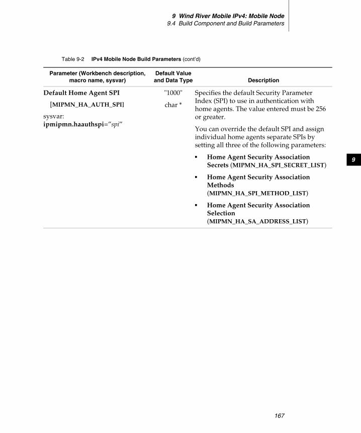
9 Wind River Mobile IPv4: Mobile Node9.4 Build Component and Build Parameters
167
9
Default Home Agent SPI
[MIPMN_HA_AUTH_SPI]
sysvar:ipmipmn.haauthspi=”spi”
"1000"
char *
Specifies the default Security Parameter Index (SPI) to use in authentication with home agents. The value entered must be 256 or greater.
You can override the default SPI and assign individual home agents separate SPIs by setting all three of the following parameters:
■ Home Agent Security Association Secrets (MIPMN_HA_SPI_SECRET_LIST)
■ Home Agent Security Association Methods (MIPMN_HA_SPI_METHOD_LIST)
■ Home Agent Security Association Selection (MIPMN_HA_SA_ADDRESS_LIST)
Table 9-2 IPv4 Mobile Node Build Parameters (cont’d)
Parameter (Workbench description, macro name, sysvar)
Default Value and Data Type Description
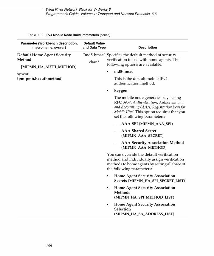
Wind River Network Stack for VxWorks 6Programmer's Guide, Volume 1: Transport and Network Protocols, 6.6
168
Default Home Agent Security Method
[MIPMN_HA_AUTH_METHOD]
sysvar:ipmipmn.haauthmethod
"md5-hmac"
char *
Specifies the default method of security verification to use with home agents. The following options are available:
■ md5-hmac
This is the default mobile IPv4 authentication method.
■ keygen
The mobile node generates keys using RFC 3957, Authentication, Authorization, and Accounting (AAA) Registration Keys for Mobile IPv4. This option requires that you set the following parameters:
– AAA SPI (MIPMN_AAA_SPI)
– AAA Shared Secret (MIPMN_AAA_SECRET)
– AAA Security Association Method (MIPMN_AAA_METHOD)
You can override the default verification method and individually assign verification methods to home agents by setting all three of the following parameters:
■ Home Agent Security Association Secrets (MIPMN_HA_SPI_SECRET_LIST)
■ Home Agent Security Association Methods (MIPMN_HA_SPI_METHOD_LIST)
■ Home Agent Security Association Selection (MIPMN_HA_SA_ADDRESS_LIST)
Table 9-2 IPv4 Mobile Node Build Parameters (cont’d)
Parameter (Workbench description, macro name, sysvar)
Default Value and Data Type Description
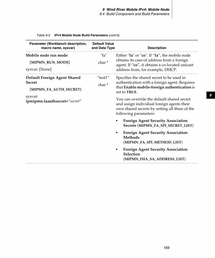
9 Wind River Mobile IPv4: Mobile Node9.4 Build Component and Build Parameters
169
9
Mobile node run mode
[MIPMN_RUN_MODE]
sysvar: [None]
"fa"
char *
Either "fa" or "co". If “fa”, the mobile node obtains its care-of address from a foreign agent. If “co”, it obtains a co-located unicast address from, for example, DHCP.
Default Foreign Agent Shared Secret
[MIPMN_FA_AUTH_SECRET]
sysvar:ipmipmn.faauthsecret=”secret”
“test1”
char *
Specifies the shared secret to be used in authentication with a foreign agent. Requires that Enable mobile-foreign authentication is set to TRUE.
You can override the default shared secret and assign individual foreign agents their own shared secrets by setting all three of the following parameters:
■ Foreign Agent Security Association Secrets (MIPMN_FA_SPI_SECRET_LIST)
■ Foreign Agent Security Association Methods (MIPMN_FA_SPI_METHOD_LIST)
■ Foreign Agent Security Association Selection (MIPMN_FHA_SA_ADDRESS_LIST)
Table 9-2 IPv4 Mobile Node Build Parameters (cont’d)
Parameter (Workbench description, macro name, sysvar)
Default Value and Data Type Description

Wind River Network Stack for VxWorks 6Programmer's Guide, Volume 1: Transport and Network Protocols, 6.6
170
Default Foreign Agent SPI
[MIPMN_FA_AUTH_SPI]
sysvar:ipmipmn.faauthspi=”spi”
"1001"
char *
Specifies the default Security Parameter Index (SPI) to be used in authentication with foreign agents. Requires that Enable mobile-foreign authentication is set to TRUE.
The value entered must be 256 or greater.
You can override the default SPI and assign individual foreign agents separate SPIs by setting all three of the following parameters:
■ Foreign Agent Security Association Secrets (MIPMN_FA_SPI_SECRET_LIST)
■ Foreign Agent Security Association Methods (MIPMN_FA_SPI_METHOD_LIST)
■ Foreign Agent Security Association Selection (MIPMN_FHA_SA_ADDRESS_LIST)
Table 9-2 IPv4 Mobile Node Build Parameters (cont’d)
Parameter (Workbench description, macro name, sysvar)
Default Value and Data Type Description
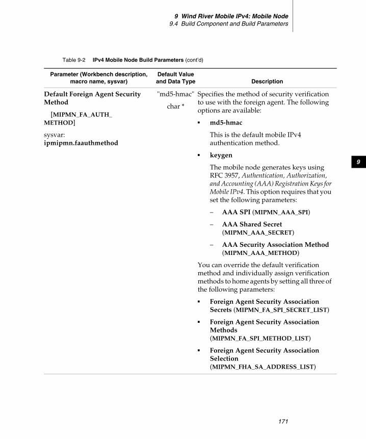
9 Wind River Mobile IPv4: Mobile Node9.4 Build Component and Build Parameters
171
9
Default Foreign Agent Security Method
[MIPMN_FA_AUTH_METHOD]
sysvar:ipmipmn.faauthmethod
"md5-hmac"
char *
Specifies the method of security verification to use with the foreign agent. The following options are available:
■ md5-hmac
This is the default mobile IPv4 authentication method.
■ keygen
The mobile node generates keys using RFC 3957, Authentication, Authorization, and Accounting (AAA) Registration Keys for Mobile IPv4. This option requires that you set the following parameters:
– AAA SPI (MIPMN_AAA_SPI)
– AAA Shared Secret (MIPMN_AAA_SECRET)
– AAA Security Association Method (MIPMN_AAA_METHOD)
You can override the default verification method and individually assign verification methods to home agents by setting all three of the following parameters:
■ Foreign Agent Security Association Secrets (MIPMN_FA_SPI_SECRET_LIST)
■ Foreign Agent Security Association Methods (MIPMN_FA_SPI_METHOD_LIST)
■ Foreign Agent Security Association Selection (MIPMN_FHA_SA_ADDRESS_LIST)
Table 9-2 IPv4 Mobile Node Build Parameters (cont’d)
Parameter (Workbench description, macro name, sysvar)
Default Value and Data Type Description
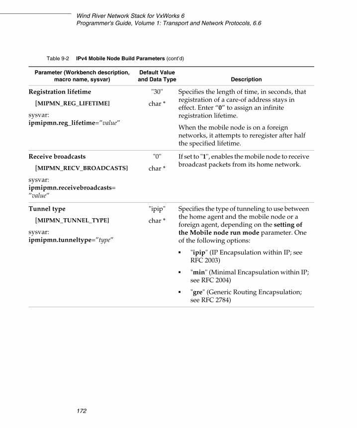
Wind River Network Stack for VxWorks 6Programmer's Guide, Volume 1: Transport and Network Protocols, 6.6
172
Registration lifetime
[MIPMN_REG_LIFETIME]
sysvar:ipmipmn.reg_lifetime=”value”
"30"
char *
Specifies the length of time, in seconds, that registration of a care-of address stays in effect. Enter “0” to assign an infinite registration lifetime.
When the mobile node is on a foreign networks, it attempts to reregister after half the specified lifetime.
Receive broadcasts
[MIPMN_RECV_BROADCASTS]
sysvar:ipmipmn.receivebroadcasts=”value”
"0"
char *
If set to "1", enables the mobile node to receive broadcast packets from its home network.
Tunnel type
[MIPMN_TUNNEL_TYPE]
sysvar:ipmipmn.tunneltype=”type”
"ipip"
char *
Specifies the type of tunneling to use between the home agent and the mobile node or a foreign agent, depending on the setting of the Mobile node run mode parameter. One of the following options:
■ "ipip" (IP Encapsulation within IP; see RFC 2003)
■ "min" (Minimal Encapsulation within IP; see RFC 2004)
■ "gre" (Generic Routing Encapsulation; see RFC 2784)
Table 9-2 IPv4 Mobile Node Build Parameters (cont’d)
Parameter (Workbench description, macro name, sysvar)
Default Value and Data Type Description
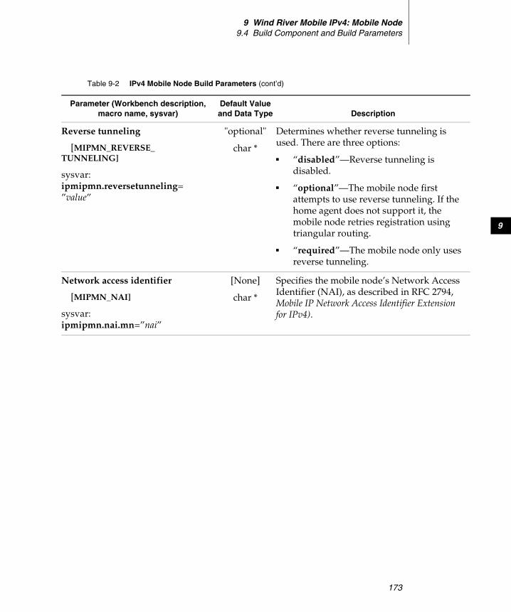
9 Wind River Mobile IPv4: Mobile Node9.4 Build Component and Build Parameters
173
9
Reverse tunneling
[MIPMN_REVERSE_TUNNELING]
sysvar:ipmipmn.reversetunneling=”value”
"optional"
char *
Determines whether reverse tunneling is used. There are three options:
■ “disabled”—Reverse tunneling is disabled.
■ “optional”—The mobile node first attempts to use reverse tunneling. If the home agent does not support it, the mobile node retries registration using triangular routing.
■ “required”—The mobile node only uses reverse tunneling.
Network access identifier
[MIPMN_NAI]
sysvar:ipmipmn.nai.mn=”nai”
[None]
char *
Specifies the mobile node’s Network Access Identifier (NAI), as described in RFC 2794, Mobile IP Network Access Identifier Extension for IPv4).
Table 9-2 IPv4 Mobile Node Build Parameters (cont’d)
Parameter (Workbench description, macro name, sysvar)
Default Value and Data Type Description
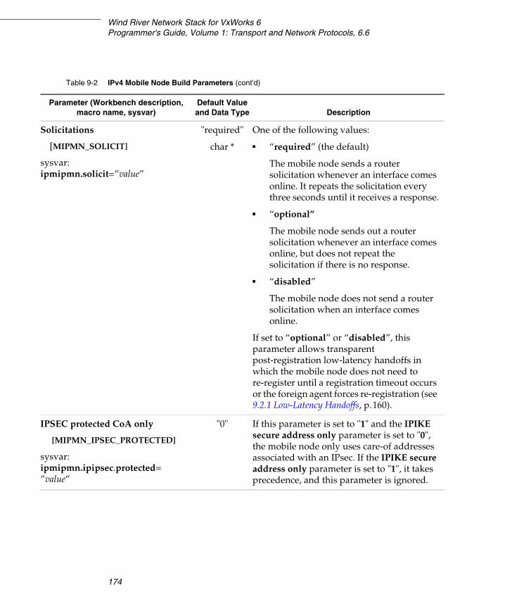
Wind River Network Stack for VxWorks 6Programmer's Guide, Volume 1: Transport and Network Protocols, 6.6
174
Solicitations
[MIPMN_SOLICIT]
sysvar:ipmipmn.solicit=”value”
"required"
char *
One of the following values:
■ “required” (the default)
The mobile node sends a router solicitation whenever an interface comes online. It repeats the solicitation every three seconds until it receives a response.
■ “optional”
The mobile node sends out a router solicitation whenever an interface comes online, but does not repeat the solicitation if there is no response.
■ “disabled”
The mobile node does not send a router solicitation when an interface comes online.
If set to “optional” or “disabled”, this parameter allows transparent post-registration low-latency handoffs in which the mobile node does not need to re-register until a registration timeout occurs or the foreign agent forces re-registration (see 9.2.1 Low-Latency Handoffs, p.160).
IPSEC protected CoA only
[MIPMN_IPSEC_PROTECTED]
sysvar:ipmipmn.ipipsec.protected=”value”
"0" If this parameter is set to "1" and the IPIKE secure address only parameter is set to "0", the mobile node only uses care-of addresses associated with an IPsec. If the IPIKE secure address only parameter is set to "1", it takes precedence, and this parameter is ignored.
Table 9-2 IPv4 Mobile Node Build Parameters (cont’d)
Parameter (Workbench description, macro name, sysvar)
Default Value and Data Type Description
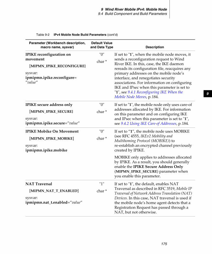
9 Wind River Mobile IPv4: Mobile Node9.4 Build Component and Build Parameters
175
9
IPIKE reconfiguration on movement
[MIPMN_IPIKE_RECONFIGURE]
sysvar:ipmipmn.ipike.reconfigure=”value”
"0"
char *
If set to "1", when the mobile node moves, it sends a reconfiguration request to Wind River IKE. In this, case, the IKE daemon rereads its configuration file, reacquires any primary addresses on the mobile node’s interface, and renegotiates security associations. For information on configuring IKE and IPsec when this parameter is set to "1", see 9.4.1 Reconfiguring IKE When the Mobile Node Moves, p.184.
IPIKE secure address only
[MIPMN_IPIKE_SECURE]
sysvar:ipmipmn.ipike.secure=”value”
"0"
char *
If set to "1", the mobile node only uses care-of addresses allocated by IKE. For information on this parameter and on configuring IKE and IPsec when this parameter is set to "1", see 9.4.2 Using IKE Care-of Addresses, p.184.
IPIKE Mobike On Movement
[MIPMN_IPIKE_MOBIKE]
sysvar:ipmipmn.ipike.mobike
"0"
char *
If set to “1”, the mobile node uses MOBIKE (see RFC 4555, IKEv2 Mobility and Multihoming Protocol (MOBIKE)) to re-establish an encrypted channel previously created by IPIKE.
MOBIKE only applies to addresses allocated by IPIKE. As a result, you should generally enable the IPIKE Secure Address Only (MIPMN_IPIKE_SECURE) parameter when you enable this parameter.
NAT Traversal
[MIPMN_NAT_T_ENABLED]
sysvar:ipmipmn.nat_t.enabled=”value”
"1"
char *
If set to "1", the default, enables NAT Traversal as described in RFC 3519, Mobile IP Traversal of Network Address Translation (NAT) Devices. In this case, NAT traversal is used if the mobile node’s home agent detects that a Registration Request has passed through a NAT, but not otherwise.
Table 9-2 IPv4 Mobile Node Build Parameters (cont’d)
Parameter (Workbench description, macro name, sysvar)
Default Value and Data Type Description

Wind River Network Stack for VxWorks 6Programmer's Guide, Volume 1: Transport and Network Protocols, 6.6
176
Forced NAT Traversal
[MIPMN_NAT_T_FORCED]
sysvar:ipmipmn.nat_t.forced=”value”
"0"
char *
If set to "1", forces NAT traversal as described in RFC 3519, even if the mobile node’s home agent does not detect that a Registration Request has passed through a NAT.
NAT Traversal keepalive
[MIPMN_NAT_T_KEEPALIVE]
sysvar:ipmipmn.nat_t.keepalive=”value”
"120"
char *
Specifies the keep-alive time interval, in seconds, to use for NAT-Traversal ICMP keep-alive messages. The keep-alive time interval is used to maintain a NAT UDP port mapping.
NAT Traversal tunnel type
[MIPMN_NAT_T_TUNNEL_TYPE]
sysvar:ipmipmn.nat_t.tunneltype=”type”
[None]
char *
Determines the type of tunneling used for NAT traversal. If no value is entered, NAT traversal tunneling uses the tunneling type specified in the Tunnel type parameter. To specify a different type of tunneling for NAT, enter one of the following:
■ "ipip" (IP Encapsulation within IP; see RFC 2003)
■ "min" (Minimal Encapsulation within IP; see RFC 2004)
■ "gre" (Generic Routing Encapsulation; see RFC 2784)
Table 9-2 IPv4 Mobile Node Build Parameters (cont’d)
Parameter (Workbench description, macro name, sysvar)
Default Value and Data Type Description
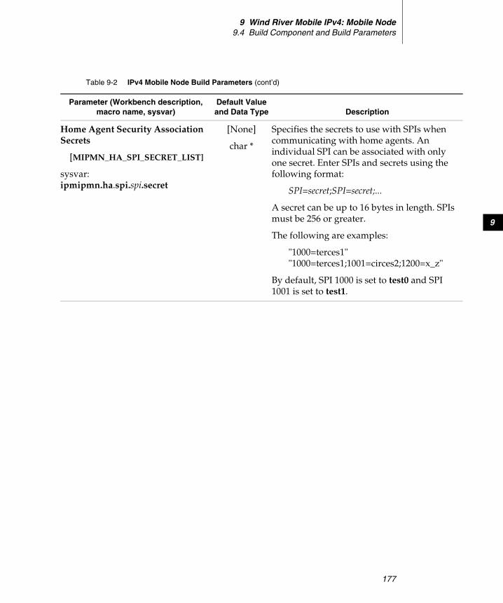
9 Wind River Mobile IPv4: Mobile Node9.4 Build Component and Build Parameters
177
9
Home Agent Security Association Secrets
[MIPMN_HA_SPI_SECRET_LIST]
sysvar:ipmipmn.ha.spi.spi.secret
[None]
char *
Specifies the secrets to use with SPIs when communicating with home agents. An individual SPI can be associated with only one secret. Enter SPIs and secrets using the following format:
SPI=secret;SPI=secret;...
A secret can be up to 16 bytes in length. SPIs must be 256 or greater.
The following are examples:
"1000=terces1""1000=terces1;1001=circes2;1200=x_z"
By default, SPI 1000 is set to test0 and SPI 1001 is set to test1.
Table 9-2 IPv4 Mobile Node Build Parameters (cont’d)
Parameter (Workbench description, macro name, sysvar)
Default Value and Data Type Description
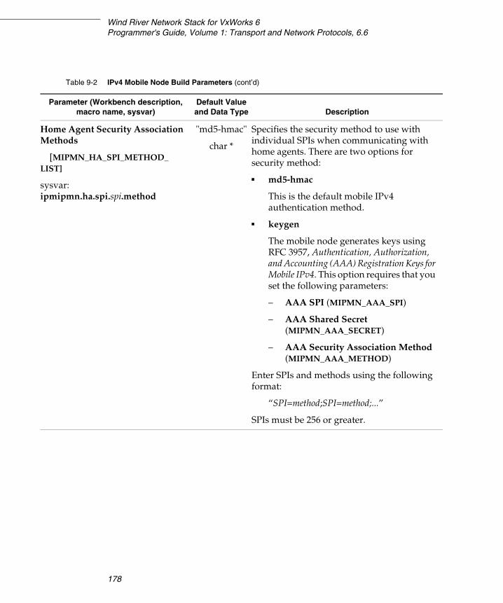
Wind River Network Stack for VxWorks 6Programmer's Guide, Volume 1: Transport and Network Protocols, 6.6
178
Home Agent Security Association Methods
[MIPMN_HA_SPI_METHOD_LIST]
sysvar:ipmipmn.ha.spi.spi.method
"md5-hmac"
char *
Specifies the security method to use with individual SPIs when communicating with home agents. There are two options for security method:
■ md5-hmac
This is the default mobile IPv4 authentication method.
■ keygen
The mobile node generates keys using RFC 3957, Authentication, Authorization, and Accounting (AAA) Registration Keys for Mobile IPv4. This option requires that you set the following parameters:
– AAA SPI (MIPMN_AAA_SPI)
– AAA Shared Secret (MIPMN_AAA_SECRET)
– AAA Security Association Method (MIPMN_AAA_METHOD)
Enter SPIs and methods using the following format:
“SPI=method;SPI=method;...”
SPIs must be 256 or greater.
Table 9-2 IPv4 Mobile Node Build Parameters (cont’d)
Parameter (Workbench description, macro name, sysvar)
Default Value and Data Type Description
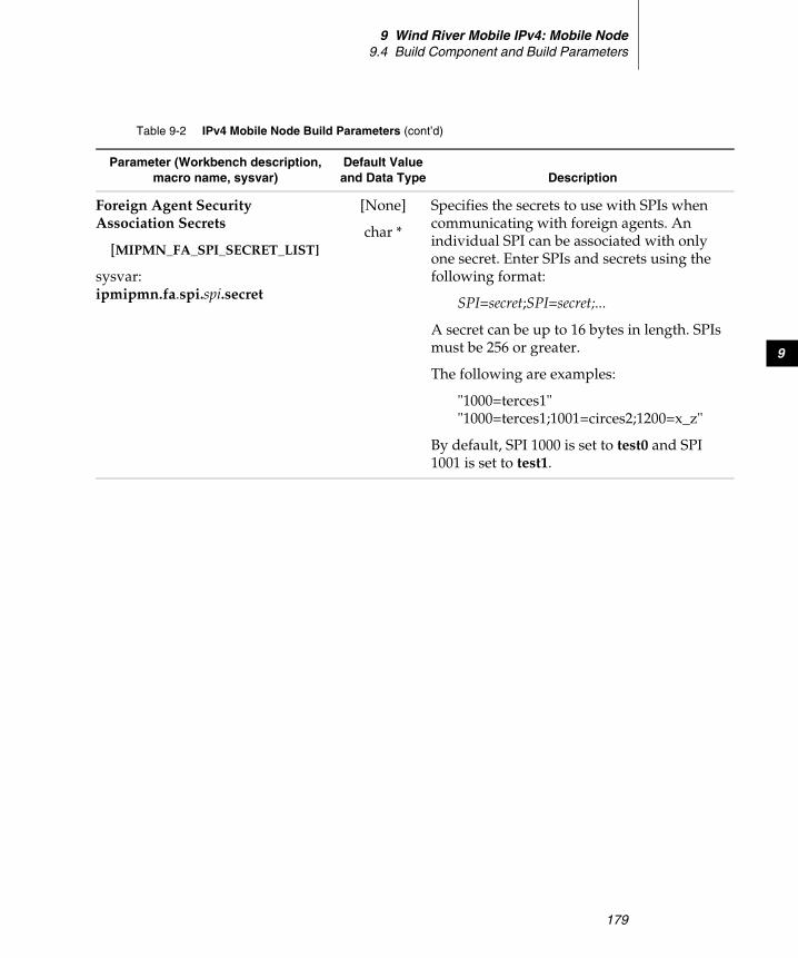
9 Wind River Mobile IPv4: Mobile Node9.4 Build Component and Build Parameters
179
9
Foreign Agent Security Association Secrets
[MIPMN_FA_SPI_SECRET_LIST]
sysvar:ipmipmn.fa.spi.spi.secret
[None]
char *
Specifies the secrets to use with SPIs when communicating with foreign agents. An individual SPI can be associated with only one secret. Enter SPIs and secrets using the following format:
SPI=secret;SPI=secret;...
A secret can be up to 16 bytes in length. SPIs must be 256 or greater.
The following are examples:
"1000=terces1""1000=terces1;1001=circes2;1200=x_z"
By default, SPI 1000 is set to test0 and SPI 1001 is set to test1.
Table 9-2 IPv4 Mobile Node Build Parameters (cont’d)
Parameter (Workbench description, macro name, sysvar)
Default Value and Data Type Description
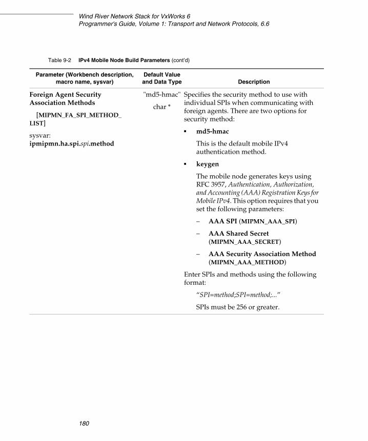
Wind River Network Stack for VxWorks 6Programmer's Guide, Volume 1: Transport and Network Protocols, 6.6
180
Foreign Agent Security Association Methods
[MIPMN_FA_SPI_METHOD_LIST]
sysvar:ipmipmn.ha.spi.spi.method
"md5-hmac"
char *
Specifies the security method to use with individual SPIs when communicating with foreign agents. There are two options for security method:
■ md5-hmac
This is the default mobile IPv4 authentication method.
■ keygen
The mobile node generates keys using RFC 3957, Authentication, Authorization, and Accounting (AAA) Registration Keys for Mobile IPv4. This option requires that you set the following parameters:
– AAA SPI (MIPMN_AAA_SPI)
– AAA Shared Secret (MIPMN_AAA_SECRET)
– AAA Security Association Method (MIPMN_AAA_METHOD)
Enter SPIs and methods using the following format:
“SPI=method;SPI=method;...”
SPIs must be 256 or greater.
Table 9-2 IPv4 Mobile Node Build Parameters (cont’d)
Parameter (Workbench description, macro name, sysvar)
Default Value and Data Type Description
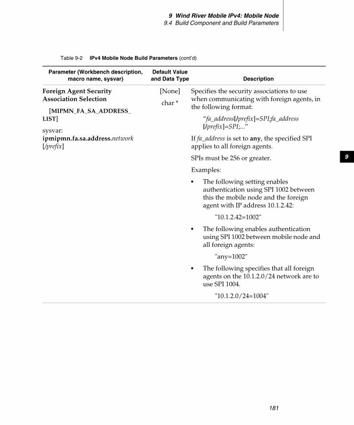
9 Wind River Mobile IPv4: Mobile Node9.4 Build Component and Build Parameters
181
9
Foreign Agent Security Association Selection
[MIPMN_FA_SA_ADDRESS_LIST]
sysvar:ipmipmn.fa.sa.address.network[/prefix]
[None]
char *
Specifies the security associations to use when communicating with foreign agents, in the following format:
“fa_address[/prefix]=SPI;fa_address[/prefix]=SPI;...”
If fa_address is set to any, the specified SPI applies to all foreign agents.
SPIs must be 256 or greater.
Examples:
■ The following setting enables authentication using SPI 1002 between this the mobile node and the foreign agent with IP address 10.1.2.42:
"10.1.2.42=1002"
■ The following enables authentication using SPI 1002 between mobile node and all foreign agents:
"any=1002"
■ The following specifies that all foreign agents on the 10.1.2.0/24 network are to use SPI 1004.
"10.1.2.0/24=1004"
Table 9-2 IPv4 Mobile Node Build Parameters (cont’d)
Parameter (Workbench description, macro name, sysvar)
Default Value and Data Type Description
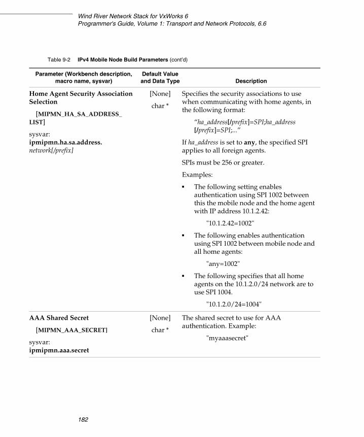
Wind River Network Stack for VxWorks 6Programmer's Guide, Volume 1: Transport and Network Protocols, 6.6
182
Home Agent Security Association Selection
[MIPMN_HA_SA_ADDRESS_LIST]
sysvar:ipmipmn.ha.sa.address.network[/prefix]
[None]
char *
Specifies the security associations to use when communicating with home agents, in the following format:
“ha_address[/prefix]=SPI;ha_address[/prefix]=SPI;...”
If ha_address is set to any, the specified SPI applies to all foreign agents.
SPIs must be 256 or greater.
Examples:
■ The following setting enables authentication using SPI 1002 between this the mobile node and the home agent with IP address 10.1.2.42:
"10.1.2.42=1002"
■ The following enables authentication using SPI 1002 between mobile node and all home agents:
"any=1002"
■ The following specifies that all home agents on the 10.1.2.0/24 network are to use SPI 1004.
"10.1.2.0/24=1004"
AAA Shared Secret
[MIPMN_AAA_SECRET]
sysvar:ipmipmn.aaa.secret
[None]
char *
The shared secret to use for AAA authentication. Example:
"myaaasecret"
Table 9-2 IPv4 Mobile Node Build Parameters (cont’d)
Parameter (Workbench description, macro name, sysvar)
Default Value and Data Type Description
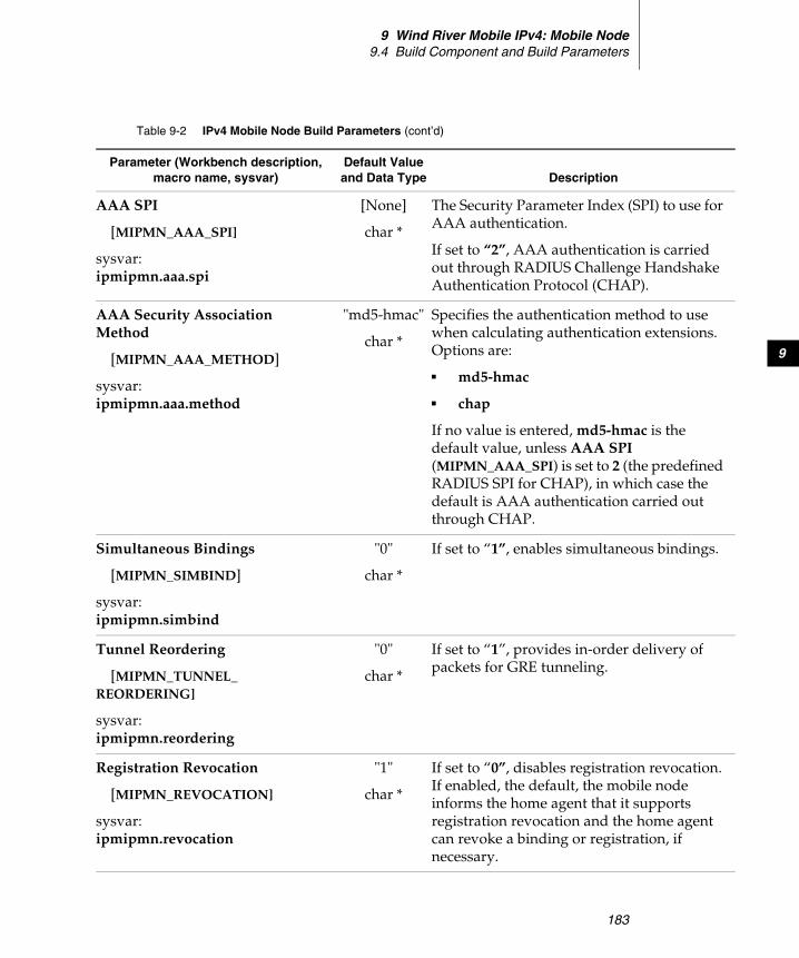
9 Wind River Mobile IPv4: Mobile Node9.4 Build Component and Build Parameters
183
9
AAA SPI
[MIPMN_AAA_SPI]
sysvar:ipmipmn.aaa.spi
[None]
char *
The Security Parameter Index (SPI) to use for AAA authentication.
If set to “2”, AAA authentication is carried out through RADIUS Challenge Handshake Authentication Protocol (CHAP).
AAA Security Association Method
[MIPMN_AAA_METHOD]
sysvar:ipmipmn.aaa.method
"md5-hmac"
char *
Specifies the authentication method to use when calculating authentication extensions. Options are:
■ md5-hmac
■ chap
If no value is entered, md5-hmac is the default value, unless AAA SPI (MIPMN_AAA_SPI) is set to 2 (the predefined RADIUS SPI for CHAP), in which case the default is AAA authentication carried out through CHAP.
Simultaneous Bindings
[MIPMN_SIMBIND]
sysvar:ipmipmn.simbind
"0"
char *
If set to “1”, enables simultaneous bindings.
Tunnel Reordering
[MIPMN_TUNNEL_REORDERING]
sysvar:ipmipmn.reordering
"0"
char *
If set to “1”, provides in-order delivery of packets for GRE tunneling.
Registration Revocation
[MIPMN_REVOCATION]
sysvar:ipmipmn.revocation
"1"
char *
If set to “0”, disables registration revocation. If enabled, the default, the mobile node informs the home agent that it supports registration revocation and the home agent can revoke a binding or registration, if necessary.
Table 9-2 IPv4 Mobile Node Build Parameters (cont’d)
Parameter (Workbench description, macro name, sysvar)
Default Value and Data Type Description
Wind River Network Stack for VxWorks 6Programmer's Guide, Volume 1: Transport and Network Protocols, 6.6
184
9.4.1 Reconfiguring IKE When the Mobile Node Moves
Setting the IPIKE reconfiguration on movement [MIPMN_IPIKE_RECONFIGURE] build parameter to "1" tells the mobile node to send a reconfigure request to Wind River IKE whenever the mobile node has moved to a new link and needs a new care-of address. When IKE receives the request, it rereads its configuration file, reacquires any primary addresses on the mobile node’s interface and renegotiates security associations.
For IKE to reconfigure itself correctly:
■ IKE should only be configured with the name of the mobile node’s interface, not an IP address, in an IPsec SA.
■ The system variable Flush keys on reconfigure [IPIKE_FLUSH_RECONFIGURE] must be set to "1" on the mobile node, so that IKE renegotiates security policies and associations when it reconfigures itself.
9.4.2 Using IKE Care-of Addresses
If you set the IPIKE secure address only [MIPMN_IPIKE_SECURE] build parameter to "1", the mobile node only uses IKE tunnel inner addresses as care-of addresses. A tunnel inner address (TIA) is an address that IKE dynamically allocates as part of the negotiation of security parameters. When IPIKE secure address only is enabled, the mobile node verifies potential care-of addresses against the IPsec security-policy database in order to make sure that an address has the security parameters necessary for being a TIA.
To use IKE TIAs:
■ The TIA address must be assigned to the mobile node’s interface as the primary address for negotiating security parameters.
■ Wind River IKE needs to be configured with its IKE_DYNAMIC_ADDRESS_MODE parameter set to “0”.
This forces security policies to allow any TIA IP address for the mobile node.
■ For the mobile node, IPsec SAs need to be configured as either of the following
address interface_name address 0.0.0.0/0
address 0.0.0.0/0 address 0.0.0.0/0
■ If the responder—for example, the home agent—to the mobile node is using Wind River IKE, it must set its IPIKE_ADDRESS_POOL_NETWORK4

9 Wind River Mobile IPv4: Mobile Node9.5 Including the Mobile Node in a Build
185
9
configuration parameter (see Wind River IKE for VxWorks 6 Programmer's Guide, 6.x).
The responder needs to set the IPIKE_ADDRESS_POOL_NETWORK4 configuration parameter for initiators that request dynamic addresses.
9.5 Including the Mobile Node in a Build
To include the mobile node in a VxWorks build, you need to create a VxWorks Image Project and include the IPv4 Mobile Node (INCLUDE_IPMIPMN) build component. You can do this through either Workbench or the vxprj command-line utility. For information on using Workbench to create a VxWorks Image Project and include build components, see the Wind River Workbench User's Guide for VxWorks. For information on using the vxprj command-line utility, see the VxWorks Command-Line Tools User’s Guide.
Once you include the IPv4 Mobile Node (INCLUDE_IPMIPMN) component in your build, you can set values for the static configuration parameters listed in Table 9-2.
9.6 Shell Commands
You can use shell commands to:
■ Inform the mobile node of its current link-layer status, for use in low-latency handoffs.
■ Display the current status of the mobile node
■ Display a history of the node’s state events.
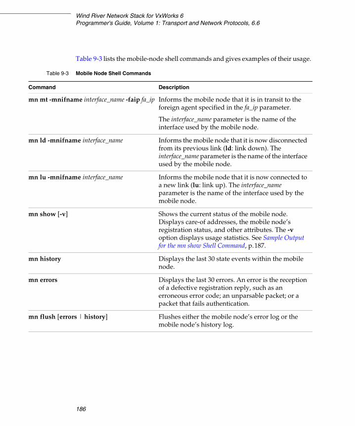
Wind River Network Stack for VxWorks 6Programmer's Guide, Volume 1: Transport and Network Protocols, 6.6
186
Table 9-3 lists the mobile-node shell commands and gives examples of their usage.
Table 9-3 Mobile Node Shell Commands
Command Description
mn mt -mnifname interface_name -faip fa_ip Informs the mobile node that it is in transit to the foreign agent specified in the fa_ip parameter.
The interface_name parameter is the name of the interface used by the mobile node.
mn ld -mnifname interface_name Informs the mobile node that it is now disconnected from its previous link (ld: link down). The interface_name parameter is the name of the interface used by the mobile node.
mn lu -mnifname interface_name Informs the mobile node that it is now connected to a new link (lu: link up). The interface_name parameter is the name of the interface used by the mobile node.
mn show [-v] Shows the current status of the mobile node. Displays care-of addresses, the mobile node’s registration status, and other attributes. The -v option displays usage statistics. See Sample Output for the mn show Shell Command, p.187.
mn history Displays the last 30 state events within the mobile node.
mn errors Displays the last 30 errors. An error is the reception of a defective registration reply, such as an erroneous error code; an unparsable packet; or a packet that fails authentication.
mn flush [errors | history] Flushes either the mobile node’s error log or the mobile node’s history log.
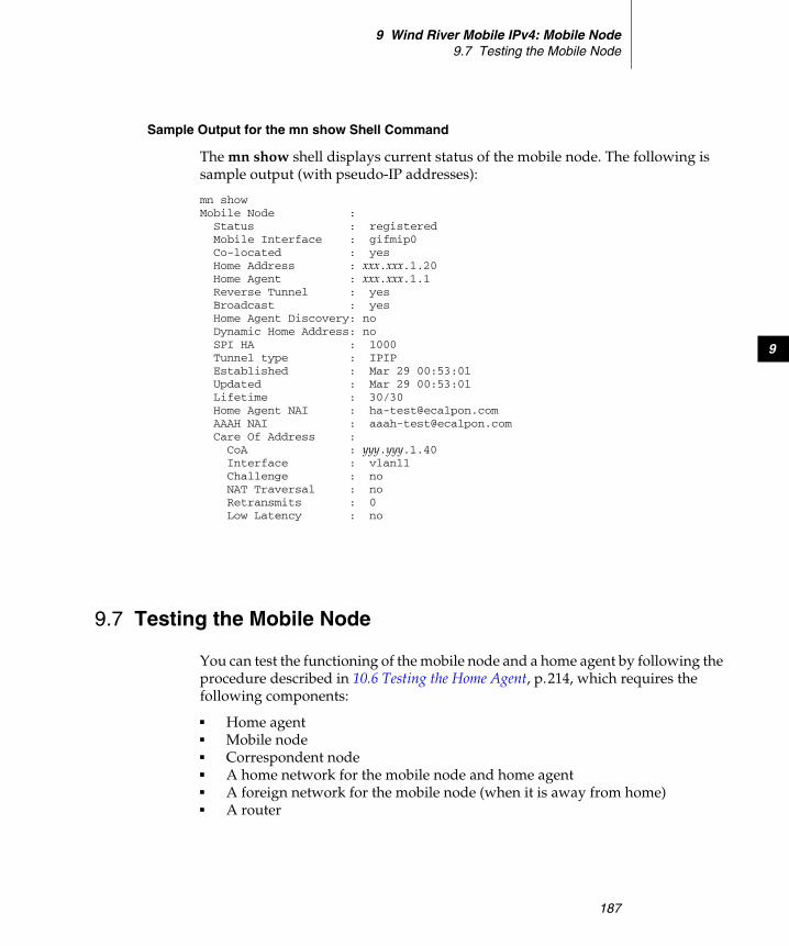
9 Wind River Mobile IPv4: Mobile Node9.7 Testing the Mobile Node
187
9
Sample Output for the mn show Shell Command
The mn show shell displays current status of the mobile node. The following is sample output (with pseudo-IP addresses):
mn showMobile Node : Status : registered Mobile Interface : gifmip0 Co-located : yes Home Address : xxx.xxx.1.20 Home Agent : xxx.xxx.1.1 Reverse Tunnel : yes Broadcast : yes Home Agent Discovery: no Dynamic Home Address: no SPI HA : 1000 Tunnel type : IPIP Established : Mar 29 00:53:01 Updated : Mar 29 00:53:01 Lifetime : 30/30 Home Agent NAI : [email protected] AAAH NAI : [email protected] Care Of Address : CoA : yyy.yyy.1.40 Interface : vlan11 Challenge : no NAT Traversal : no Retransmits : 0 Low Latency : no
9.7 Testing the Mobile Node
You can test the functioning of the mobile node and a home agent by following the procedure described in 10.6 Testing the Home Agent, p.214, which requires the following components:
■ Home agent■ Mobile node■ Correspondent node■ A home network for the mobile node and home agent■ A foreign network for the mobile node (when it is away from home)■ A router
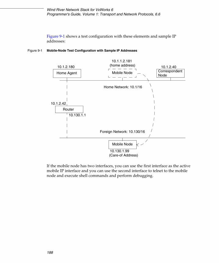
Wind River Network Stack for VxWorks 6Programmer's Guide, Volume 1: Transport and Network Protocols, 6.6
188
Figure 9-1 shows a test configuration with these elements and sample IP addresses:
If the mobile node has two interfaces, you can use the first interface as the active mobile IP interface and you can use the second interface to telnet to the mobile node and execute shell commands and perform debugging.
Figure 9-1 Mobile-Node Test Configuration with Sample IP Addresses
Router
Correspondent10.1.2.180
NodeHome Agent Mobile Node
10.1.1.2.181
10.1.2.40
Home Network: 10.1/16
(home address)
Mobile Node
Foreign Network: 10.130/16
10.130.1.99(Care-of Address)
10.1.2.42
10.130.1.1

189
10Wind River Mobile IPv4:
Home Agent
10.1 Introduction 189
10.2 Conformance to Standards 190
10.3 Build Components and Build Parameters 191
10.4 Including the Home Agent in a Build 210
10.5 Shell Commands 211
10.6 Testing the Home Agent 214
10.1 Introduction
This chapter describes the Wind River implementation of a home agent for IPv4. For a general overview of Mobile IP, see 8. Wind River Mobile IP: Overview.
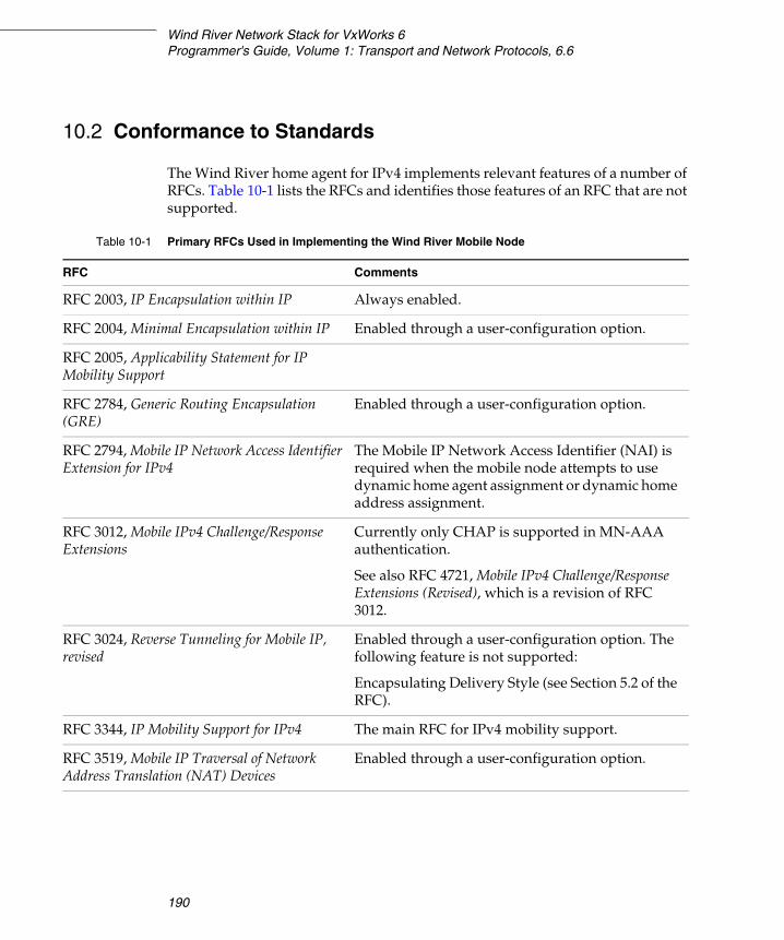
Wind River Network Stack for VxWorks 6Programmer's Guide, Volume 1: Transport and Network Protocols, 6.6
190
10.2 Conformance to Standards
The Wind River home agent for IPv4 implements relevant features of a number of RFCs. Table 10-1 lists the RFCs and identifies those features of an RFC that are not supported.
Table 10-1 Primary RFCs Used in Implementing the Wind River Mobile Node
RFC Comments
RFC 2003, IP Encapsulation within IP Always enabled.
RFC 2004, Minimal Encapsulation within IP Enabled through a user-configuration option.
RFC 2005, Applicability Statement for IP Mobility Support
RFC 2784, Generic Routing Encapsulation (GRE)
Enabled through a user-configuration option.
RFC 2794, Mobile IP Network Access Identifier Extension for IPv4
The Mobile IP Network Access Identifier (NAI) is required when the mobile node attempts to use dynamic home agent assignment or dynamic home address assignment.
RFC 3012, Mobile IPv4 Challenge/Response Extensions
Currently only CHAP is supported in MN-AAA authentication.
See also RFC 4721, Mobile IPv4 Challenge/Response Extensions (Revised), which is a revision of RFC 3012.
RFC 3024, Reverse Tunneling for Mobile IP, revised
Enabled through a user-configuration option. The following feature is not supported:
Encapsulating Delivery Style (see Section 5.2 of the RFC).
RFC 3344, IP Mobility Support for IPv4 The main RFC for IPv4 mobility support.
RFC 3519, Mobile IP Traversal of Network Address Translation (NAT) Devices
Enabled through a user-configuration option.
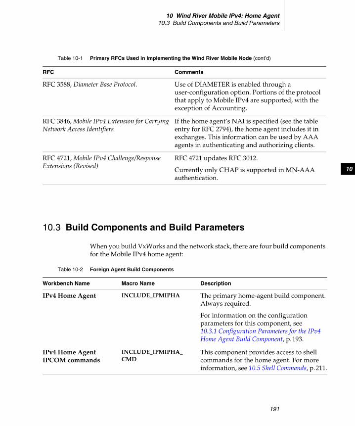
10 Wind River Mobile IPv4: Home Agent10.3 Build Components and Build Parameters
191
10
10.3 Build Components and Build Parameters
When you build VxWorks and the network stack, there are four build components for the Mobile IPv4 home agent:
RFC 3588, Diameter Base Protocol. Use of DIAMETER is enabled through a user-configuration option. Portions of the protocol that apply to Mobile IPv4 are supported, with the exception of Accounting.
RFC 3846, Mobile IPv4 Extension for Carrying Network Access Identifiers
If the home agent’s NAI is specified (see the table entry for RFC 2794), the home agent includes it in exchanges. This information can be used by AAA agents in authenticating and authorizing clients.
RFC 4721, Mobile IPv4 Challenge/Response Extensions (Revised)
RFC 4721 updates RFC 3012.
Currently only CHAP is supported in MN-AAA authentication.
Table 10-1 Primary RFCs Used in Implementing the Wind River Mobile Node (cont’d)
RFC Comments
Table 10-2 Foreign Agent Build Components
Workbench Name Macro Name Description
IPv4 Home Agent INCLUDE_IPMIPHA The primary home-agent build component. Always required.
For information on the configuration parameters for this component, see 10.3.1 Configuration Parameters for the IPv4 Home Agent Build Component, p.193.
IPv4 Home Agent IPCOM commands
INCLUDE_IPMIPHA_CMD
This component provides access to shell commands for the home agent. For more information, see 10.5 Shell Commands, p.211.
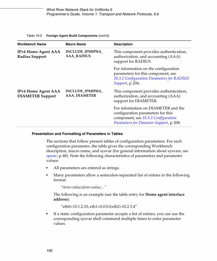
Wind River Network Stack for VxWorks 6Programmer's Guide, Volume 1: Transport and Network Protocols, 6.6
192
Presentation and Formatting of Parameters in Tables
The sections that follow present tables of configuration parameters. For each configuration parameter, the table gives the corresponding Workbench description, macro name, and sysvar (for general information about sysvars, see sysvar, p.48). Note the following characteristics of parameters and parameter values:
■ All parameters are entered as strings.
■ Many parameters allow a semicolon-separated list of entries in the following format:
“item=value;item=value;...”
The following is an example (see the table entry for Home agent interface address):
“eth0=10.1.2.10; eth1=0.0.0.0;eth2=10.2.3.4”
■ If a static configuration parameter accepts a list of entries, you can use the corresponding sysvar shell command multiple times to enter parameter values.
IPv4 Home Agent AAA Radius Support
INCLUDE_IPMIPHA_AAA_RADIUS
This component provides authentication, authorization, and accounting (AAA) support for RADIUS.
For information on the configuration parameters for this component, see 10.3.2 Configuration Parameters for RADIUS Support, p.204..
IPv4 Home Agent AAA DIAMETER Support
INCLUDE_IPMIPHA_AAA_DIAMETER
This component provides authentication, authorization, and accounting (AAA) support for DIAMETER.
For information on DIAMETER and the configuration parameters for this component, see 10.3.3 Configuration Parameters for Diameter Support, p.208.
Table 10-2 Foreign Agent Build Components (cont’d)
Workbench Name Macro Name Description
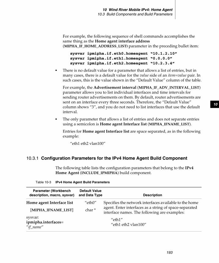
10 Wind River Mobile IPv4: Home Agent10.3 Build Components and Build Parameters
193
10
For example, the following sequence of shell commands accomplishes the same thing as the Home agent interface address (MIPHA_IF_HOME_ADDRESS_LIST) parameter in the preceding bullet item:
sysvar ipmipha.if.eth0.homeagent “10.1.2.10”sysvar ipmipha.if.eth1.homeagent “0.0.0.0”sysvar ipmipha.if.eth2.homeagent “10.2.3.4”
■ There is no default value for a parameter that allows a list of entries, but in many cases, there is a default value for the value side of an item=value pair. In such cases, this is the value shown in the “Default Value” column of the table.
For example, the Advertisement interval (MIPHA_IF_ADV_INTERVAL_LIST) parameter allows you to list individual interfaces and time intervals for sending router advertisements on them. By default, router advertisements are sent on an interface every three seconds. Therefore, the “Default Value” column shows “3”, and you do not need to list interfaces that use the default interval.
■ The only parameter that allows a list of entries and does not separate entries using a semicolon is Home agent Interface list (MIPHA_IFNAME_LIST).
Entries for Home agent Interface list are space separated, as in the following example:
“eth1 eth2 vlan100”
10.3.1 Configuration Parameters for the IPv4 Home Agent Build Component
The following table lists the configuration parameters that belong to the IPv4 Home Agent (INCLUDE_IPMIPHA) build component.
Table 10-3 IPv4 Home Agent Build Parameters
Parameter (Workbench description, macro, sysvar)
Default Value and Data Type Description
Home agent Interface list
[MIPHA_IFNAME_LIST]
sysvar:ipmipha.interfaces=”if_name”
“eth0”
char *
Specifies the network interfaces available to the home agent. Enter interfaces as a string of space-separated interface names. The following are examples:
“eth1”“eth1 eth2 vlan100”

Wind River Network Stack for VxWorks 6Programmer's Guide, Volume 1: Transport and Network Protocols, 6.6
194
Registration lifetime
[MIPHA_REG_LIFETIME]
sysvar:ipmipha.reg_lifetime=”seconds”
“30”
char *
Specifies the length of time, in seconds, that a mobile node’s registration is maintained. If the mobile node does not reregister its foreign address within this time, the home agent drops the registration.
Replay protection
[MIPHA_REPLAY_PROTECTION]
sysvar:ipmipha.timestampreplayprotectionmaxdiff=”seconds”
"7"
char *
Specifies the maximum time difference, in seconds, allowed between the current time and the timestamp in a mobile node’s registration request. If set to 0, no validation is performed, and any time difference is allowed.
HA Network access identifier
[MIPHA_HA_NAI]
sysvar:ipmipha.nai.ha=”nai”
[None]
char *
(Optional) Specifies the network access identifier (NAI) of the home agent (see RFC 3846). The NAI is a unique, fully qualified domain name, in the form:
host@domain
The name preceding the “@” symbol must contain at least 3 characters.
Security Parameter Index (SPI) list
[MIPHA_SPI_LIST]
sysvar:ipmipha.spi.spi.secret=”secret”
“test0”
char *
Specifies the secrets to use with Security Parameter Indexes (SPIs). An individual SPI can be associated with only one secret. Enter SPIs and secrets using the following format:
SPI=secret;SPI=secret;...
A secret can be up to 16 bytes in length.
The following are examples:
"1000=terces1""1000=terces1;1001=circes2;1200=x_z"
Table 10-3 IPv4 Home Agent Build Parameters (cont’d)
Parameter (Workbench description, macro, sysvar)
Default Value and Data Type Description
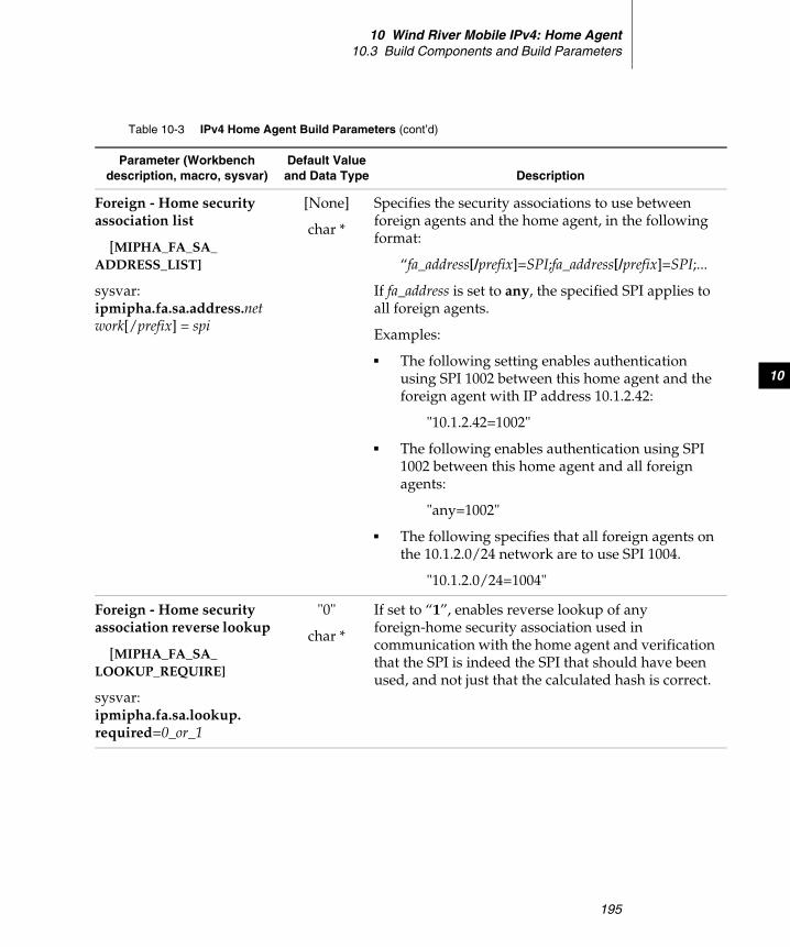
10 Wind River Mobile IPv4: Home Agent10.3 Build Components and Build Parameters
195
10
Foreign - Home security association list
[MIPHA_FA_SA_ADDRESS_LIST]
sysvar:ipmipha.fa.sa.address.network[/prefix] = spi
[None]
char *
Specifies the security associations to use between foreign agents and the home agent, in the following format:
“fa_address[/prefix]=SPI;fa_address[/prefix]=SPI;...
If fa_address is set to any, the specified SPI applies to all foreign agents.
Examples:
■ The following setting enables authentication using SPI 1002 between this home agent and the foreign agent with IP address 10.1.2.42:
"10.1.2.42=1002"
■ The following enables authentication using SPI 1002 between this home agent and all foreign agents:
"any=1002"
■ The following specifies that all foreign agents on the 10.1.2.0/24 network are to use SPI 1004.
"10.1.2.0/24=1004"
Foreign - Home security association reverse lookup
[MIPHA_FA_SA_LOOKUP_REQUIRE]
sysvar:ipmipha.fa.sa.lookup.required=0_or_1
"0"
char *
If set to “1”, enables reverse lookup of any foreign-home security association used in communication with the home agent and verification that the SPI is indeed the SPI that should have been used, and not just that the calculated hash is correct.
Table 10-3 IPv4 Home Agent Build Parameters (cont’d)
Parameter (Workbench description, macro, sysvar)
Default Value and Data Type Description
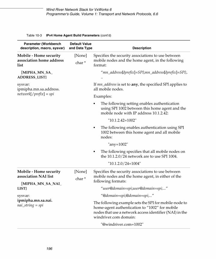
Wind River Network Stack for VxWorks 6Programmer's Guide, Volume 1: Transport and Network Protocols, 6.6
196
Mobile - Home security association home address list
[MIPHA_MN_SA_ADDRESS_LIST]
sysvar:ipmipha.mn.sa.address.network[/prefix] = spi
[None]
char *
Specifies the security associations to use between mobile nodes and the home agent, in the following format:
“mn_address[/prefix]=SPI;mn_address[/prefix]=SPI;...
If mn_address is set to any, the specified SPI applies to all mobile nodes.
Examples:
■ The following setting enables authentication using SPI 1002 between this home agent and the mobile node with IP address 10.1.2.42:
"10.1.2.42=1002"
■ The following enables authentication using SPI 1002 between this home agent and all mobile nodes:
"any=1002"
■ The following specifies that all mobile nodes on the 10.1.2.0/24 network are to use SPI 1004.
"10.1.2.0/24=1004"
Mobile - Home security association NAI list
[MIPHA_MN_SA_NAI_LIST]
sysvar:ipmipha.mn.sa.nai.nai_string = spi
[None]
char *
Specifies the security associations to use between mobile nodes and the home agent, in either of the following formats:
“user@domain=spi;user@domain=spi;...”
“@domain=spi;@domain=spi;...”
The following example sets the SPI for mobile-node to home-agent authentication to “1002” for mobile nodes that use a network access identifier (NAI) in the windriver.com domain:
"@windriver.com=1002"
Table 10-3 IPv4 Home Agent Build Parameters (cont’d)
Parameter (Workbench description, macro, sysvar)
Default Value and Data Type Description
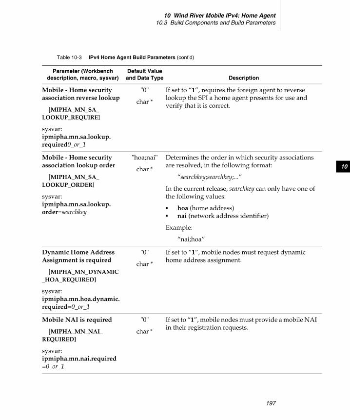
10 Wind River Mobile IPv4: Home Agent10.3 Build Components and Build Parameters
197
10
Mobile - Home security association reverse lookup
[MIPHA_MN_SA_LOOKUP_REQUIRE]
sysvar:ipmipha.mn.sa.lookup.required0_or_1
"0"
char *
If set to “1”, requires the foreign agent to reverse lookup the SPI a home agent presents for use and verify that it is correct.
Mobile - Home security association lookup order
[MIPHA_MN_SA_LOOKUP_ORDER]
sysvar:ipmipha.mn.sa.lookup.order=searchkey
"hoa;nai"
char *
Determines the order in which security associations are resolved, in the following format:
“searchkey;searchkey;...”
In the current release, searchkey can only have one of the following values:
■ hoa (home address)■ nai (network address identifier)
Example:
“nai;hoa”
Dynamic Home Address Assignment is required
[MIPHA_MN_DYNAMIC_HOA_REQUIRED]
sysvar:ipmipha.mn.hoa.dynamic.required=0_or_1
"0"
char *
If set to “1”, mobile nodes must request dynamic home address assignment.
Mobile NAI is required
[MIPHA_MN_NAI_REQUIRED]
sysvar:ipmipha.mn.nai.required=0_or_1
"0"
char *
If set to “1”, mobile nodes must provide a mobile NAI in their registration requests.
Table 10-3 IPv4 Home Agent Build Parameters (cont’d)
Parameter (Workbench description, macro, sysvar)
Default Value and Data Type Description
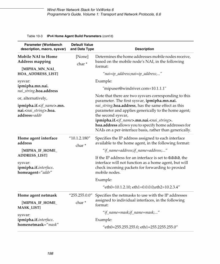
Wind River Network Stack for VxWorks 6Programmer's Guide, Volume 1: Transport and Network Protocols, 6.6
198
Mobile NAI to Home Address mapping
[MIPHA_MN_NAI_HOA_ADDRESS_LIST]
sysvar: ipmipha.mn.nai.nai_string.hoa.address
or, alternatively,
ipmipha.if.<if_name>.mn.nai.<nai_string>.hoa.address=addr
[None]
char *
Determines the home addresses mobile nodes receive, based on the mobile node’s NAI, in the following format:
“nai=ip_address;nai=ip_address;...”
Example:
"[email protected]=10.1.1.1"
Note that there are two sysvars corresponding to this parameter. The first sysvar, ipmipha.mn.nai.nai_string.hoa.address, has the same effect as this parameter and applies generically to the home agent; the second sysvar, ipmipha.if.<if_name>.mn.nai.<nai_string>.hoa.address allows you to specify home addresses for NAIs on a per-interface basis, rather than generically.
Home agent interface address
[MIPHA_IF_HOME_ADDRESS_LIST]
sysvar:ipmipha.if.interface.homeagent=”addr”
“10.1.2.180”
char *
Specifies the IP address assigned to each interface available to the home agent, in the following format:
“if_name=address;if_name=address;...”
If the IP address for an interface is set to 0.0.0.0, the interface will not function as a home agent, but will check incoming packets for forwarding to proxied mobile nodes.
Example:
“eth0=10.1.2.10; eth1=0.0.0.0;eth2=10.2.3.4”
Home agent netmask
[MIPHA_IF_HOME_MASK_LIST]
sysvar:ipmipha.if.interface.homenetmask=”mask”
“255.255.0.0”
char *
Specifies the netmasks to use with the IP addresses assigned to individual interfaces, in the following format:
“if_name=mask;if_name=mask;...”
Example:
“eth0=255.255.255.0; eth1=255.2255.255.0”
Table 10-3 IPv4 Home Agent Build Parameters (cont’d)
Parameter (Workbench description, macro, sysvar)
Default Value and Data Type Description
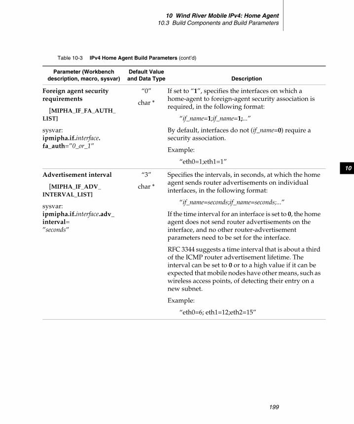
10 Wind River Mobile IPv4: Home Agent10.3 Build Components and Build Parameters
199
10
Foreign agent security requirements
[MIPHA_IF_FA_AUTH_LIST]
sysvar:ipmipha.if.interface.fa_auth=”0_or_1”
“0”
char *
If set to “1”, specifies the interfaces on which a home-agent to foreign-agent security association is required, in the following format:
“if_name=1;if_name=1;...”
By default, interfaces do not (if_name=0) require a security association.
Example:
“eth0=1;eth1=1”
Advertisement interval
[MIPHA_IF_ADV_INTERVAL_LIST]
sysvar:ipmipha.if.interface.adv_interval=”seconds”
“3”
char *
Specifies the intervals, in seconds, at which the home agent sends router advertisements on individual interfaces, in the following format:
“if_name=seconds;if_name=seconds;...”
If the time interval for an interface is set to 0, the home agent does not send router advertisements on the interface, and no other router-advertisement parameters need to be set for the interface.
RFC 3344 suggests a time interval that is about a third of the ICMP router advertisement lifetime. The interval can be set to 0 or to a high value if it can be expected that mobile nodes have other means, such as wireless access points, of detecting their entry on a new subnet.
Example:
“eth0=6; eth1=12;eth2=15”
Table 10-3 IPv4 Home Agent Build Parameters (cont’d)
Parameter (Workbench description, macro, sysvar)
Default Value and Data Type Description
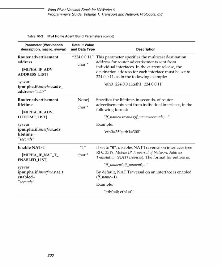
Wind River Network Stack for VxWorks 6Programmer's Guide, Volume 1: Transport and Network Protocols, 6.6
200
Router advertisement address
[MIPHA_IF_ADV_ADDRESS_LIST]
sysvar:ipmipha.if.interface.adv_address=”addr”
“224.0.0.11”
char *
This parameter specifies the multicast destination address for router advertisements sent from individual interfaces. In the current release, the destination address for each interface must be set to 224.0.0.11, as in the following example:
"eth0=224.0.0.11;eth1=224.0.0.11"
Router advertisement lifetime
[MIPHA_IF_ADV_LIFETIME_LIST]
sysvar:ipmipha.if.interface.adv_lifetime=”seconds”
[None]
char *
Specifies the lifetime, in seconds, of router advertisements sent from individual interfaces, in the following format:
“if_name=seconds;if_name=seconds;...”
Example:
"eth0=350;eth1=300"
Enable NAT-T
[MIPHA_IF_NAT_T_ENABLED_LIST]
sysvar:ipmipha.if.interface.nat_t.enabled=”seconds”
“1”
char *
If set to “0”, disables NAT Traversal on interfaces (see RFC 3519, Mobile IP Traversal of Network Address Translation (NAT) Devices). The format for entries is:
“if_name=0;if_name=0;...”
By default, NAT Traversal on an interface is enabled (if_name=1).
Example:
“eth0=0; eth1=0”
Table 10-3 IPv4 Home Agent Build Parameters (cont’d)
Parameter (Workbench description, macro, sysvar)
Default Value and Data Type Description

10 Wind River Mobile IPv4: Home Agent10.3 Build Components and Build Parameters
201
10
NAT-T keepalive
[MIPHA_IF_NAT_T_KEEPALIVE_LIST]
sysvar:ipmipha.if.interface.nat_t.keepalive=”seconds”
“0”
char *
For individual interfaces, specifies the keep-alive time interval, in seconds, to use for NAT-Traversal ICMP keep-alive messages. The keep-alive time interval is used to maintain a NAT UDP port mapping. The format for entries is:
“if_name=seconds;if_name=seconds;...”
By default, the NAT-T keep-alive interval for an interface is 0 seconds, which allows a foreign agent or mobile node to determine the keep-alive interval. If a value other than 0 is specified, foreign agents or mobile nodes requesting NAT-T must use the specified value as the keep-alive timeout.
Example:
“eth0=135; eth1=100”
Interface IPIP tunneling
[MIPHA_IF_IPIP_TUNNEL_ENABLED_LIST]
sysvar:ipmipha.if.if_name.ipip=0_or_1
"1"
char *
If set to “0”, disables the use of IPIP tunneling (IP- Encapsulation-within-IP tunneling; see RFC 2003) on individual interfaces. The format for entries is:
“if_name=0;if_name=0;...”
By default, IPIP tunneling is enabled on an interface.
Example:
“eth0=0; eth1=0”
Table 10-3 IPv4 Home Agent Build Parameters (cont’d)
Parameter (Workbench description, macro, sysvar)
Default Value and Data Type Description
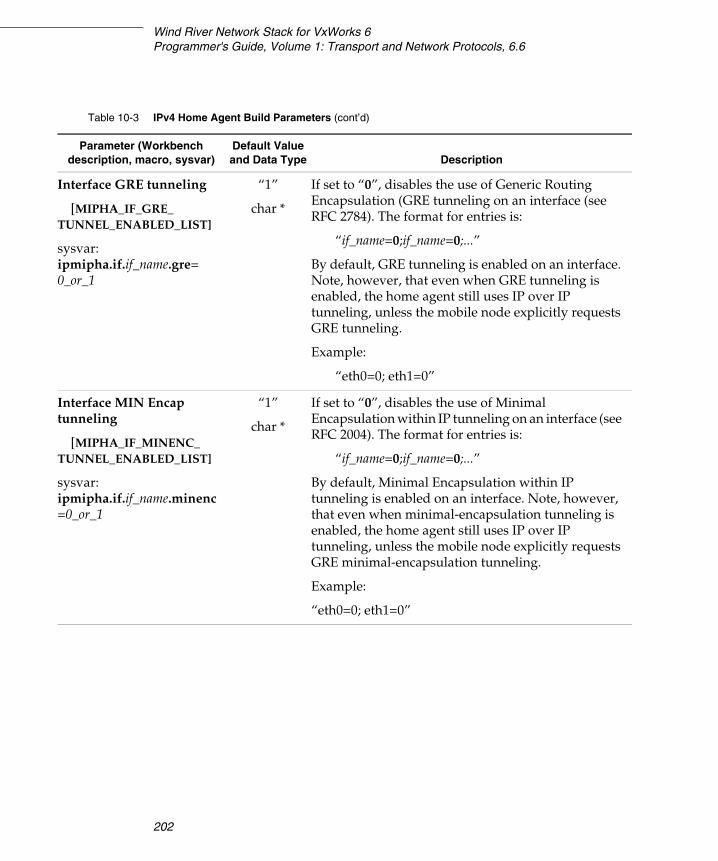
Wind River Network Stack for VxWorks 6Programmer's Guide, Volume 1: Transport and Network Protocols, 6.6
202
Interface GRE tunneling
[MIPHA_IF_GRE_TUNNEL_ENABLED_LIST]
sysvar:ipmipha.if.if_name.gre=0_or_1
“1”
char *
If set to “0”, disables the use of Generic Routing Encapsulation (GRE tunneling on an interface (see RFC 2784). The format for entries is:
“if_name=0;if_name=0;...”
By default, GRE tunneling is enabled on an interface. Note, however, that even when GRE tunneling is enabled, the home agent still uses IP over IP tunneling, unless the mobile node explicitly requests GRE tunneling.
Example:
“eth0=0; eth1=0”
Interface MIN Encap tunneling
[MIPHA_IF_MINENC_TUNNEL_ENABLED_LIST]
sysvar:ipmipha.if.if_name.minenc=0_or_1
“1”
char *
If set to “0”, disables the use of Minimal Encapsulation within IP tunneling on an interface (see RFC 2004). The format for entries is:
“if_name=0;if_name=0;...”
By default, Minimal Encapsulation within IP tunneling is enabled on an interface. Note, however, that even when minimal-encapsulation tunneling is enabled, the home agent still uses IP over IP tunneling, unless the mobile node explicitly requests GRE minimal-encapsulation tunneling.
Example:
“eth0=0; eth1=0”
Table 10-3 IPv4 Home Agent Build Parameters (cont’d)
Parameter (Workbench description, macro, sysvar)
Default Value and Data Type Description
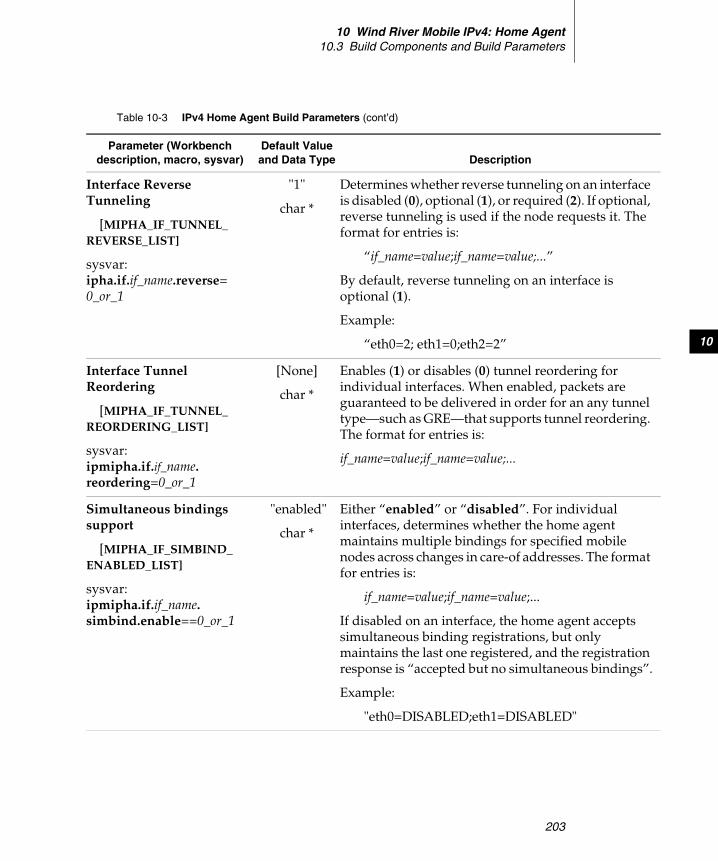
10 Wind River Mobile IPv4: Home Agent10.3 Build Components and Build Parameters
203
10
Interface Reverse Tunneling
[MIPHA_IF_TUNNEL_REVERSE_LIST]
sysvar:ipha.if.if_name.reverse=0_or_1
"1"
char *
Determines whether reverse tunneling on an interface is disabled (0), optional (1), or required (2). If optional, reverse tunneling is used if the node requests it. The format for entries is:
“if_name=value;if_name=value;...”
By default, reverse tunneling on an interface is optional (1).
Example:
“eth0=2; eth1=0;eth2=2”
Interface Tunnel Reordering
[MIPHA_IF_TUNNEL_REORDERING_LIST]
sysvar:ipmipha.if.if_name.reordering=0_or_1
[None]
char *
Enables (1) or disables (0) tunnel reordering for individual interfaces. When enabled, packets are guaranteed to be delivered in order for an any tunnel type—such as GRE—that supports tunnel reordering. The format for entries is:
if_name=value;if_name=value;...
Simultaneous bindings support
[MIPHA_IF_SIMBIND_ENABLED_LIST]
sysvar:ipmipha.if.if_name.simbind.enable==0_or_1
"enabled"
char *
Either “enabled” or “disabled”. For individual interfaces, determines whether the home agent maintains multiple bindings for specified mobile nodes across changes in care-of addresses. The format for entries is:
if_name=value;if_name=value;...
If disabled on an interface, the home agent accepts simultaneous binding registrations, but only maintains the last one registered, and the registration response is “accepted but no simultaneous bindings”.
Example:
"eth0=DISABLED;eth1=DISABLED"
Table 10-3 IPv4 Home Agent Build Parameters (cont’d)
Parameter (Workbench description, macro, sysvar)
Default Value and Data Type Description

Wind River Network Stack for VxWorks 6Programmer's Guide, Volume 1: Transport and Network Protocols, 6.6
204
10.3.2 Configuration Parameters for RADIUS Support
The following table lists the configuration parameters that belong to the IPv4 Home Agent AAA Radius Support (INCLUDE_IPMIPHA_AAA_RADIUS) build component.
Max number of simultaneous bindings
[MIPHA_IF_SIMBIND_MAX_LIST]
sysvar:ipmipha.if.if_name.simbind.max=max_bindings
"3"
char *
For interfaces that allow multiple simultaneous bindings, this parameter specifies the maximum number of simultaneous bindings individual interfaces can maintain. The format for entries is:
if_name=value;if_name=value;...
Example:
"eth2=4;eth3=5"
Revocation Support
[MIPHA_IF_REVOCATION_ENABLED_LIST]
sysvar:ipmipha.if.if_name.revocation=0_or_1
[None]
char *
Enables (1) or disables (0) registration revocation on individual interfaces. The format for entries is:
if_name=value;if_name=value;...
Example:
“eth0=1;eth2=2”
Table 10-3 IPv4 Home Agent Build Parameters (cont’d)
Parameter (Workbench description, macro, sysvar)
Default Value and Data Type Description
Table 10-4 IPv4 Home Agent AAA Radius Build Parameters
Parameter (Workbench description, macro, sysvar)
Default Value and Data Type Description
RADIUS Access Support
[MIPHA_AAA_RADIUS_ACCESS]
sysvar:ipmipha.aaa.radius.access=”0_or_1”
"disabled"
char *
If set to “enabled”, the home agent uses RADIUS. By default, RADIUS is not used.
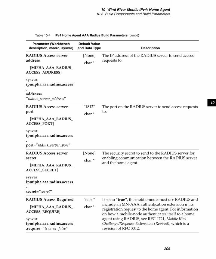
10 Wind River Mobile IPv4: Home Agent10.3 Build Components and Build Parameters
205
10
RADIUS Access server address
[MIPHA_AAA_RADIUS_ACCESS_ADDRESS]
sysvar:ipmipha.aaa.radius.access.address=”radius_server_address”
[None]
char *
The IP address of the RADIUS server to send access requests to.
RADIUS Access server port
[MIPHA_AAA_RADIUS_ACCESS_PORT]
sysvar:ipmipha.aaa.radius.access.port=”radius_server_port”
"1812"
char *
The port on the RADIUS server to send access requests to.
RADIUS Access server secret
[MIPHA_AAA_RADIUS_ACCESS_SECRET]
sysvar:ipmipha.aaa.radius.access.secret=”secret”
[None]
char *
The security secret to send to the RADIUS server for enabling communication between the RADIUS server and the home agent.
RADIUS Access Required
[MIPHA_AAA_RADIUS_ACCESS_REQUIRE]
sysvar:ipmipha.aaa.radius.access.require=”true_or_false”
"false"
char *
If set to “true”, the mobile-node must use RADIUS and include an MN-AAA authentication extension in its registration request to the home agent. For information on how a mobile-node authenticates itself to a home agent using RADIUS, see RFC 4721, Mobile IPv4 Challenge/Response Extensions (Revised), which is a revision of RFC 3012.
Table 10-4 IPv4 Home Agent AAA Radius Build Parameters (cont’d)
Parameter (Workbench description, macro, sysvar)
Default Value and Data Type Description
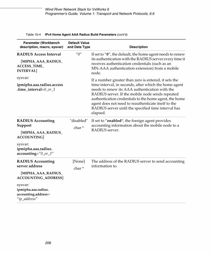
Wind River Network Stack for VxWorks 6Programmer's Guide, Volume 1: Transport and Network Protocols, 6.6
206
RADIUS Access Interval
[MIPHA_AAA_RADIUS_ACCESS_TIME_INTERVAL]
sysvar:
ipmipha.aaa.radius.access.time_interval=0_or_1
“0” If set to “0”, the default, the home agent needs to renew its authentication with the RADIUS server every time it receives authentication credentials (such as an MN-AAA authentication extension) from a mobile node.
If a number greater than zero is entered, it sets the time-interval, in seconds, after which the home agent needs to renew its AAA authentication with the RADIUS server. If the mobile node sends repeated authentication credentials to the home agent, the home agent does not need to reauthenticate itself to the RADIUS server until the specified time interval has elapsed.
RADIUS Accounting Support
[MIPHA_AAA_RADIUS_ACCOUNTING]
sysvar:ipmipha.aaa.radius.accounting=”0_or_1”
"disabled"
char *
If set to “enabled”, the foreign agent provides accounting information about the mobile node to a RADIUS server.
RADIUS Accounting server address
[MIPHA_AAA_RADIUS_ACCOUNTING_ADDRESS]
sysvar:ipmipha.aaa.radius.accounting.address=“ip_address”
[None]
char *
The address of the RADIUS server to send accounting information to.
Table 10-4 IPv4 Home Agent AAA Radius Build Parameters (cont’d)
Parameter (Workbench description, macro, sysvar)
Default Value and Data Type Description

10 Wind River Mobile IPv4: Home Agent10.3 Build Components and Build Parameters
207
10
RADIUS Accounting server port
[MIPHA_AAA_RADIUS_ACCOUNTING_PORT]
sysvar:ipmipha.aaa.radius.accounting.port=”port”
"1813"
char *
The port to send RADIUS accounting information to.
RADIUS Accounting server secret
[MIPHA_AAA_RADIUS_ACCOUNTING_SECRET]
sysvar:ipmipha.aaa.radius.accounting.sec=”secret”
[None]
char *
The security secret to send to the RADIUS server for accounting in order to enable communication between the server and the foreign agent.
RADIUS local address
[MIPHA_AAA_RADIUS_LOCAL_ADDRESS]
sysvar:ipmipha.aaa.radius.local.address=”local_address”
[None]
char *
The IP address the foreign agent uses for all communication with a RADIUS server.
RADIUS AAAH NAI
[MIPHA_AAA_RADIUS_NAI]
sysvar:ipmipha.aaa.radius.nai=nai
[None]
char *
The AAAH NAI that the home agent appends to registration replies, so that the mobile node knows what AAAH server authenticated it. The mobile node can append the AAAH NAI to all its subsequent registration requests to ensure that the same AAA server authenticates it through an entire session. The AAAH NAI may be necessary if a number of AAA servers are running for load balancing purposes.
Table 10-4 IPv4 Home Agent AAA Radius Build Parameters (cont’d)
Parameter (Workbench description, macro, sysvar)
Default Value and Data Type Description
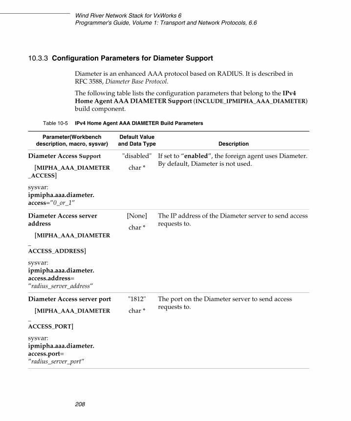
Wind River Network Stack for VxWorks 6Programmer's Guide, Volume 1: Transport and Network Protocols, 6.6
208
10.3.3 Configuration Parameters for Diameter Support
Diameter is an enhanced AAA protocol based on RADIUS. It is described in RFC 3588, Diameter Base Protocol.
The following table lists the configuration parameters that belong to the IPv4 Home Agent AAA DIAMETER Support (INCLUDE_IPMIPHA_AAA_DIAMETER) build component.
Table 10-5 IPv4 Home Agent AAA DIAMETER Build Parameters
Parameter(Workbench description, macro, sysvar)
Default Value and Data Type Description
Diameter Access Support
[MIPHA_AAA_DIAMETER_ACCESS]
sysvar:ipmipha.aaa.diameter.access=”0_or_1”
"disabled"
char *
If set to “enabled”, the foreign agent uses Diameter. By default, Diameter is not used.
Diameter Access server address
[MIPHA_AAA_DIAMETER_ACCESS_ADDRESS]
sysvar:ipmipha.aaa.diameter.access.address=”radius_server_address”
[None]
char *
The IP address of the Diameter server to send access requests to.
Diameter Access server port
[MIPHA_AAA_DIAMETER_ACCESS_PORT]
sysvar:ipmipha.aaa.diameter.access.port=”radius_server_port”
"1812"
char *
The port on the Diameter server to send access requests to.
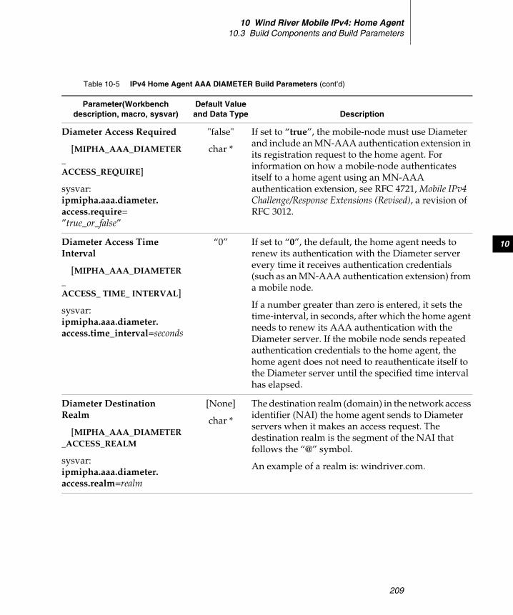
10 Wind River Mobile IPv4: Home Agent10.3 Build Components and Build Parameters
209
10
Diameter Access Required
[MIPHA_AAA_DIAMETER_ACCESS_REQUIRE]
sysvar:ipmipha.aaa.diameter.access.require=”true_or_false”
"false"
char *
If set to “true”, the mobile-node must use Diameter and include an MN-AAA authentication extension in its registration request to the home agent. For information on how a mobile-node authenticates itself to a home agent using an MN-AAA authentication extension, see RFC 4721, Mobile IPv4 Challenge/Response Extensions (Revised), a revision of RFC 3012.
Diameter Access Time Interval
[MIPHA_AAA_DIAMETER_ACCESS_ TIME_ INTERVAL]
sysvar:ipmipha.aaa.diameter.access.time_interval=seconds
“0” If set to “0”, the default, the home agent needs to renew its authentication with the Diameter server every time it receives authentication credentials (such as an MN-AAA authentication extension) from a mobile node.
If a number greater than zero is entered, it sets the time-interval, in seconds, after which the home agent needs to renew its AAA authentication with the Diameter server. If the mobile node sends repeated authentication credentials to the home agent, the home agent does not need to reauthenticate itself to the Diameter server until the specified time interval has elapsed.
Diameter Destination Realm
[MIPHA_AAA_DIAMETER_ACCESS_REALM
sysvar:ipmipha.aaa.diameter.access.realm=realm
[None]
char *
The destination realm (domain) in the network access identifier (NAI) the home agent sends to Diameter servers when it makes an access request. The destination realm is the segment of the NAI that follows the “@” symbol.
An example of a realm is: windriver.com.
Table 10-5 IPv4 Home Agent AAA DIAMETER Build Parameters (cont’d)
Parameter(Workbench description, macro, sysvar)
Default Value and Data Type Description
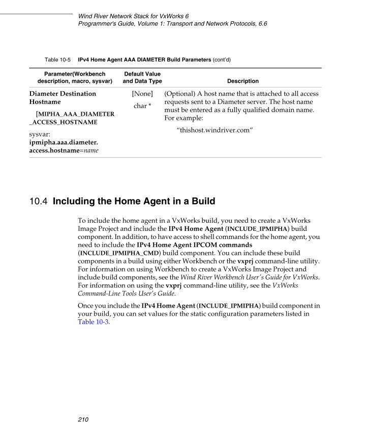
Wind River Network Stack for VxWorks 6Programmer's Guide, Volume 1: Transport and Network Protocols, 6.6
210
10.4 Including the Home Agent in a Build
To include the home agent in a VxWorks build, you need to create a VxWorks Image Project and include the IPv4 Home Agent (INCLUDE_IPMIPHA) build component. In addition, to have access to shell commands for the home agent, you need to include the IPv4 Home Agent IPCOM commands (INCLUDE_IPMIPHA_CMD) build component. You can include these build components in a build using either Workbench or the vxprj command-line utility. For information on using Workbench to create a VxWorks Image Project and include build components, see the Wind River Workbench User's Guide for VxWorks. For information on using the vxprj command-line utility, see the VxWorks Command-Line Tools User’s Guide.
Once you include the IPv4 Home Agent (INCLUDE_IPMIPHA) build component in your build, you can set values for the static configuration parameters listed in Table 10-3.
Diameter Destination Hostname
[MIPHA_AAA_DIAMETER_ACCESS_HOSTNAME
sysvar:ipmipha.aaa.diameter.access.hostname=name
[None]
char *
(Optional) A host name that is attached to all access requests sent to a Diameter server. The host name must be entered as a fully qualified domain name. For example:
“thishost.windriver.com”
Table 10-5 IPv4 Home Agent AAA DIAMETER Build Parameters (cont’d)
Parameter(Workbench description, macro, sysvar)
Default Value and Data Type Description

10 Wind River Mobile IPv4: Home Agent10.5 Shell Commands
211
10
10.5 Shell Commands
You can use home-agent shell commands to display information about current mobile-node registrations, support for tunneling, and errors that have occurred at the home agent.
Table 10-6 lists the home-agent shell commands.
Table 10-6 Mobile IPv4 Home Agent Shell Commands
Command Description
ha list Lists all mobile nodes currently registered with the home agent and identifies the type of care-of address used by the mobile node (co-located or not co-located), the types of tunneling enabled, and whether NAT traversal is in effect.
For sample output, see 10.5.1 Sample Output for the ha list Shell Command, p.213.
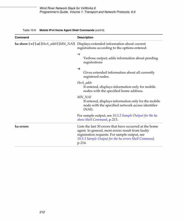
Wind River Network Stack for VxWorks 6Programmer's Guide, Volume 1: Transport and Network Protocols, 6.6
212
ha show [-v] [-a] [HoA_addr] [MN_NAI] Displays extended information about current registrations according to the options entered:
-v Verbose output; adds information about pending registrations
-aGives extended information about all currently registered nodes.
HoA_addrIf entered, displays information only for mobile nodes with the specified home address.
MN_NAIIf entered, displays information only for the mobile node with the specified network access identifier (NAI).
For sample output, see 10.5.2 Sample Output for the ha show Shell Command, p.213.
ha errors Lists the last 30 errors that have occurred at the home agent. In general, most errors result from faulty registration requests. For sample output, see 10.5.3 Sample Output for the ha errors Shell Command, p.214.
Table 10-6 Mobile IPv4 Home Agent Shell Commands (cont’d)
Command Description
10 Wind River Mobile IPv4: Home Agent10.5 Shell Commands
213
10
10.5.1 Sample Output for the ha list Shell Command
The ha list shell command lists all mobile nodes currently registered with the home agent and gives status information about pending and completed registrations, tunneling support, and whether NAT traversal is in effect. Status information is provided as follows:
The following is sample output:
>ha listHome Address Care of Address Interface Lifetime Flags192.168.1.20 192.168.1.40 vlan133 20/30 BTD
10.5.2 Sample Output for the ha show Shell Command
The ha show shell command displays information about current registrations, based on the command options entered. The following is sample output:
>ha show -v -a192.168.1.20:Creation : May 02 12:54:54Interface : vlan133Mobile NAI : [email protected] Agent NAI: [email protected] NAI : [email protected] 192.168.1.40:Creation : May 02 12:54:54Last updated : May 02 12:54:54Lifetime requested: 30Lifetime remaining: 17Mode : co-locatedBroadcast : yesReverse tunnel : yesSPI MH : 1000Tunnel type : IPIPNat traversal : no
Symbol Description
B Accepts broadcasts on behalf of the mobile node.D Mobile node uses co-location mode.G GRE tunneling supported.M Minimal Encapsulation within IP tunneling supported.T Reverse tunneling is enabled.* NAT Traversal is in effect.
Wind River Network Stack for VxWorks 6Programmer's Guide, Volume 1: Transport and Network Protocols, 6.6
214
10.5.3 Sample Output for the ha errors Shell Command
The ha error shell command lists the most recent errors (up to 30) that have occurred at the home agent. The following is sample output:
>ha errorsMay 02 13:02:39: [code=131 src=192.168.1.40 if=vlan133 coa=192.168.1.4]mobile-home extension failed authentication
10.6 Testing the Home Agent
This section provides an example showing how you can test the home agent. It requires the following components:
■ Home agent■ Mobile node■ Correspondent node■ A home network for the mobile node and home agent■ A foreign network for the mobile node (when it is away from home)■ A router
Figure 10-1 shows a test configuration with these elements and sample IP addresses.
If the mobile node has two interfaces, you can use the first interface as the active mobile IP interface and you can use the second interface to telnet to the mobile node and execute shell commands and perform debugging.
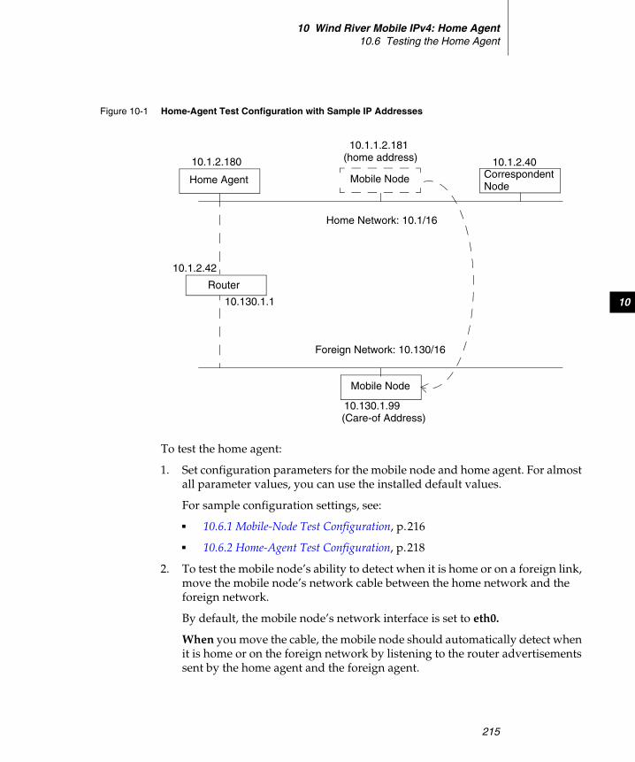
10 Wind River Mobile IPv4: Home Agent10.6 Testing the Home Agent
215
10
To test the home agent:
1. Set configuration parameters for the mobile node and home agent. For almost all parameter values, you can use the installed default values.
For sample configuration settings, see:
■ 10.6.1 Mobile-Node Test Configuration, p.216
■ 10.6.2 Home-Agent Test Configuration, p.218
2. To test the mobile node’s ability to detect when it is home or on a foreign link, move the mobile node’s network cable between the home network and the foreign network.
By default, the mobile node’s network interface is set to eth0.
When you move the cable, the mobile node should automatically detect when it is home or on the foreign network by listening to the router advertisements sent by the home agent and the foreign agent.
Figure 10-1 Home-Agent Test Configuration with Sample IP Addresses
Router
Correspondent10.1.2.180
NodeHome Agent Mobile Node
10.1.1.2.181
10.1.2.40
Home Network: 10.1/16
(home address)
Mobile Node
Foreign Network: 10.130/16
10.130.1.99(Care-of Address)
10.1.2.42
10.130.1.1
Wind River Network Stack for VxWorks 6Programmer's Guide, Volume 1: Transport and Network Protocols, 6.6
216
3. When the mobile node moves to the foreign network, to trigger the mobile node’s detection of the new network and to verify that the mobile node receives a new care-of address:
a. Change the IP address assigned to the mobile node’s network interface using shell commands as in the following example:
ifconfig eth0 inet delete 10.1.2.181ifconfig eth0 inet add 10.130.1.99
b. Change the default route (home gateway) used by the mobile node:
route delete default 10.1.1.1route add default 10.130.1.1
If the mobile node has two interfaces, you can maintain the node’s mobile IP connections by using the mobile node’s first interface (eth0, in the example) for mobile IP and telnetting to the mobile node’s second interface for executing shell commands.
Note that when the mobile node returns to its home network, you do not need to reconfigure it using shell commands. When the mobile node receives router advertisements from the home agent, it automatically resets its IP address, netmask, and default gateway to conform to the home agent.
10.6.1 Mobile-Node Test Configuration
In keeping with Figure 10-1, the following are sample configuration settings for the mobile node:
Table 10-7 Test Configuration for the Mobile Node
Parameter Value
Mobile Node Interface
[MIPMN_IFNAME]
“eth0”
Home agent IPv4 address
[MIPMN_HOME_AGENT]
“10.1.2.180”
Home address
[MIPMN_HOME_ADDRESS]
“10.1.2.181”
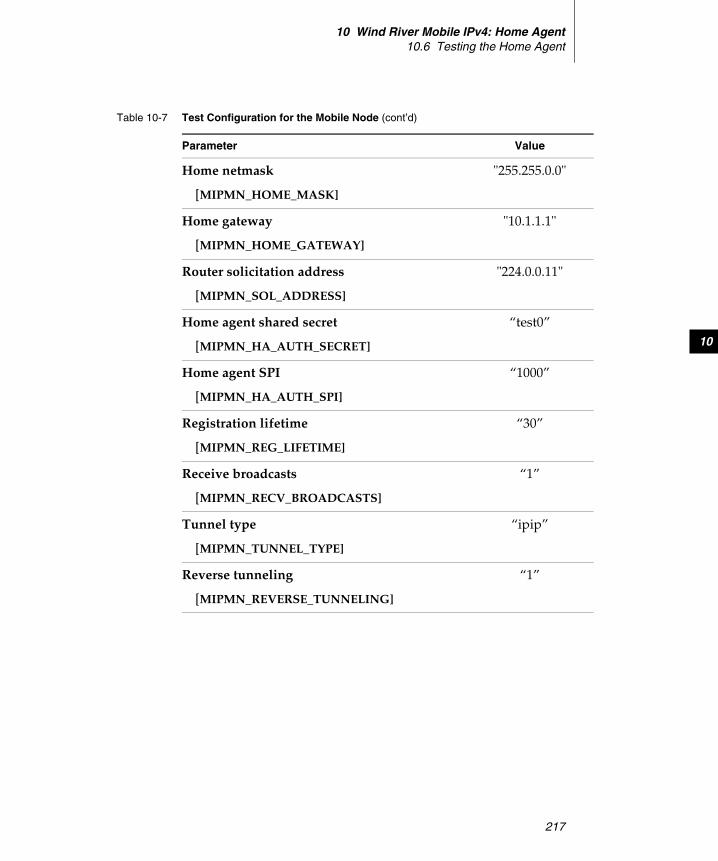
10 Wind River Mobile IPv4: Home Agent10.6 Testing the Home Agent
217
10
Home netmask
[MIPMN_HOME_MASK]
"255.255.0.0"
Home gateway
[MIPMN_HOME_GATEWAY]
"10.1.1.1"
Router solicitation address
[MIPMN_SOL_ADDRESS]
"224.0.0.11"
Home agent shared secret
[MIPMN_HA_AUTH_SECRET]
“test0”
Home agent SPI
[MIPMN_HA_AUTH_SPI]
“1000”
Registration lifetime
[MIPMN_REG_LIFETIME]
“30”
Receive broadcasts
[MIPMN_RECV_BROADCASTS]
“1”
Tunnel type
[MIPMN_TUNNEL_TYPE]
“ipip”
Reverse tunneling
[MIPMN_REVERSE_TUNNELING]
“1”
Table 10-7 Test Configuration for the Mobile Node (cont’d)
Parameter Value
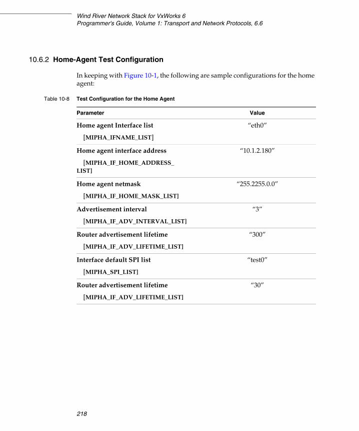
Wind River Network Stack for VxWorks 6Programmer's Guide, Volume 1: Transport and Network Protocols, 6.6
218
10.6.2 Home-Agent Test Configuration
In keeping with Figure 10-1, the following are sample configurations for the home agent:
Table 10-8 Test Configuration for the Home Agent
Parameter Value
Home agent Interface list
[MIPHA_IFNAME_LIST]
“eth0”
Home agent interface address
[MIPHA_IF_HOME_ADDRESS_LIST]
“10.1.2.180”
Home agent netmask
[MIPHA_IF_HOME_MASK_LIST]
“255.2255.0.0”
Advertisement interval
[MIPHA_IF_ADV_INTERVAL_LIST]
“3”
Router advertisement lifetime
[MIPHA_IF_ADV_LIFETIME_LIST]
“300”
Interface default SPI list
[MIPHA_SPI_LIST]
“test0”
Router advertisement lifetime
[MIPHA_IF_ADV_LIFETIME_LIST]
“30”
219
11Wind River Mobile IPv4:
Foreign Agent
11.1 Introduction 219
11.2 Low-latency handoffs 220
11.3 Conformance to Standards 221
11.4 Build Components and Build Parameters 223
11.5 Including the Foreign Agent in a Build 242
11.6 Shell Commands 243
11.7 Testing the Foreign Agent 247
11.1 Introduction
This chapter describes the Wind River implementation of a foreign agent for IPv4. For a general overview of Mobile IP see 8. Wind River Mobile IP: Overview.
Wind River Network Stack for VxWorks 6Programmer's Guide, Volume 1: Transport and Network Protocols, 6.6
220
11.2 Low-latency handoffs
The Wind River Mobile IPv4 foreign agent supports low-latency handoffs as described in the IETF Internet-Draft Low Latency Handoffs in Mobile IPv4. The draft proposes three ways of reducing delays in registering a new care-of address when the mobile node moves from one foreign agent (the “old” foreign agent) to another foreign agent (the “new” foreign agent):
■ Pre-registration handoff
This approach allows the mobile node to communicate with a new foreign agent in order to obtain a new care-of address while it is still connected to the old foreign agent.
■ Post-registration handoff
This allows data to be delivered to the mobile node at a new foreign agent before the process of registering the mobile node’s new care-of address has completed. Data is delivered using bidirectional tunneling between the old and the new foreign agents.
■ Combined handoff
In this case, the pre-registration and post-registration handoffs are carried out in parallel.
The current implementation supports all three methods.
Layer-2 Triggers
Low-latency handoffs are performed through the use of layer-2 (L2) triggers. An L2 trigger occurs at a foreign agent (one type of L2 trigger also occurs at a mobile node) and provides information from layer 2 to layer 3 about the current location or status of the mobile node either before or after a handoff occurs. The draft specification defines four types of L2 triggers:
■ L2-ST (source trigger)
Occurs at the old foreign agent, informing it that the mobile node is moving to a new foreign agent and that an L2 handoff (a connection to a foreign link) is about to occur.
■ L2-TT (target trigger)
Occurs at the new foreign agent, informing it that a mobile node is about to be handed off to it.
■ L2-LD (link down)
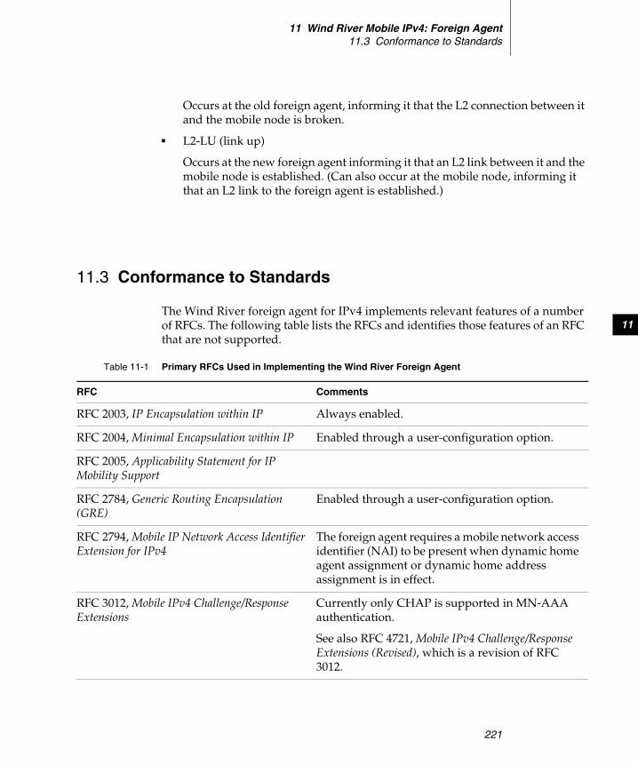
11 Wind River Mobile IPv4: Foreign Agent11.3 Conformance to Standards
221
11
Occurs at the old foreign agent, informing it that the L2 connection between it and the mobile node is broken.
■ L2-LU (link up)
Occurs at the new foreign agent informing it that an L2 link between it and the mobile node is established. (Can also occur at the mobile node, informing it that an L2 link to the foreign agent is established.)
11.3 Conformance to Standards
The Wind River foreign agent for IPv4 implements relevant features of a number of RFCs. The following table lists the RFCs and identifies those features of an RFC that are not supported.
Table 11-1 Primary RFCs Used in Implementing the Wind River Foreign Agent
RFC Comments
RFC 2003, IP Encapsulation within IP Always enabled.
RFC 2004, Minimal Encapsulation within IP Enabled through a user-configuration option.
RFC 2005, Applicability Statement for IP Mobility Support
RFC 2784, Generic Routing Encapsulation (GRE)
Enabled through a user-configuration option.
RFC 2794, Mobile IP Network Access Identifier Extension for IPv4
The foreign agent requires a mobile network access identifier (NAI) to be present when dynamic home agent assignment or dynamic home address assignment is in effect.
RFC 3012, Mobile IPv4 Challenge/Response Extensions
Currently only CHAP is supported in MN-AAA authentication.
See also RFC 4721, Mobile IPv4 Challenge/Response Extensions (Revised), which is a revision of RFC 3012.

Wind River Network Stack for VxWorks 6Programmer's Guide, Volume 1: Transport and Network Protocols, 6.6
222
RFC 3024, Reverse Tunneling for Mobile IP, revised
Enabled through a user-configuration option. The following feature is not supported:
Encapsulating Delivery Style (see Section 5.2 of the RFC).
RFC 3344, IP Mobility Support for IPv4 The main RFC for IPv4 mobility support.
RFC 3519, Mobile IP Traversal of Network Address Translation (NAT) Devices
Enabled through a user-configuration option.
RFC 3588, Diameter Base Protocol. Use of Diameter is enabled through a user-configuration option. Portions of the protocol that apply to Mobile IPv4 are supported, with the exception of Accounting.
RFC 3846, Mobile IPv4 Extension for Carrying Network Access Identifiers
RFC 4004, Diameter Mobile IPv4 Application Enabled through a user-configuration option.
RFC 4721, Mobile IPv4 Challenge/Response Extensions (Revised)
RFC 4721 updates RFC 3012.
Currently only CHAP is supported in MN-AAA authentication.
IETF draft, Low Latency Handoffs in Mobile IPv4
For a brief description of low-latency handoff methods, see 11.2 Low-latency handoffs, p.220.
Table 11-1 Primary RFCs Used in Implementing the Wind River Foreign Agent (cont’d)
RFC Comments
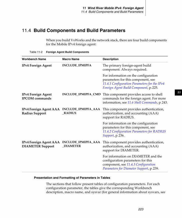
11 Wind River Mobile IPv4: Foreign Agent11.4 Build Components and Build Parameters
223
11
11.4 Build Components and Build Parameters
When you build VxWorks and the network stack, there are four build components for the Mobile IPv4 foreign agent:
Presentation and Formatting of Parameters in Tables
The sections that follow present tables of configuration parameters. For each configuration parameter, the tables give the corresponding Workbench description, macro name, and sysvar (for general information about sysvars, see
Table 11-2 Foreign Agent Build Components
Workbench Name Macro Name Description
IPv4 Foreign Agent INCLUDE_IPMIPFA The primary foreign-agent build component. Always required.
For information on the configuration parameters for this component, see 11.4.1 Configuration Parameters for the IPv4 Foreign Agent Build Component, p.225.
IPv4 Foreign Agent IPCOM commands
INCLUDE_IPMIPFA_CMD This component provides access to shell commands for the foreign agent. For more information, see 11.6 Shell Commands, p.243.
IPv4 Foreign Agent AAA Radius Support
INCLUDE_IPMIPFA_AAA_RADIUS
This component provides authentication, authorization, and accounting (AAA) support for RADIUS.
For information on the configuration parameters for this component, see 11.4.2 Configuration Parameters for RADIUS Support, p.236.
IPv4 Foreign Agent AAA DIAMETER Support
INCLUDE_IPMIPFA_AAA_DIAMETER
This component provides authentication, authorization, and accounting (AAA) support for DIAMETER.
For information on DIAMETER and the configuration parameters for this component, see 11.4.3 Configuration Parameters for Diameter Support, p.239.
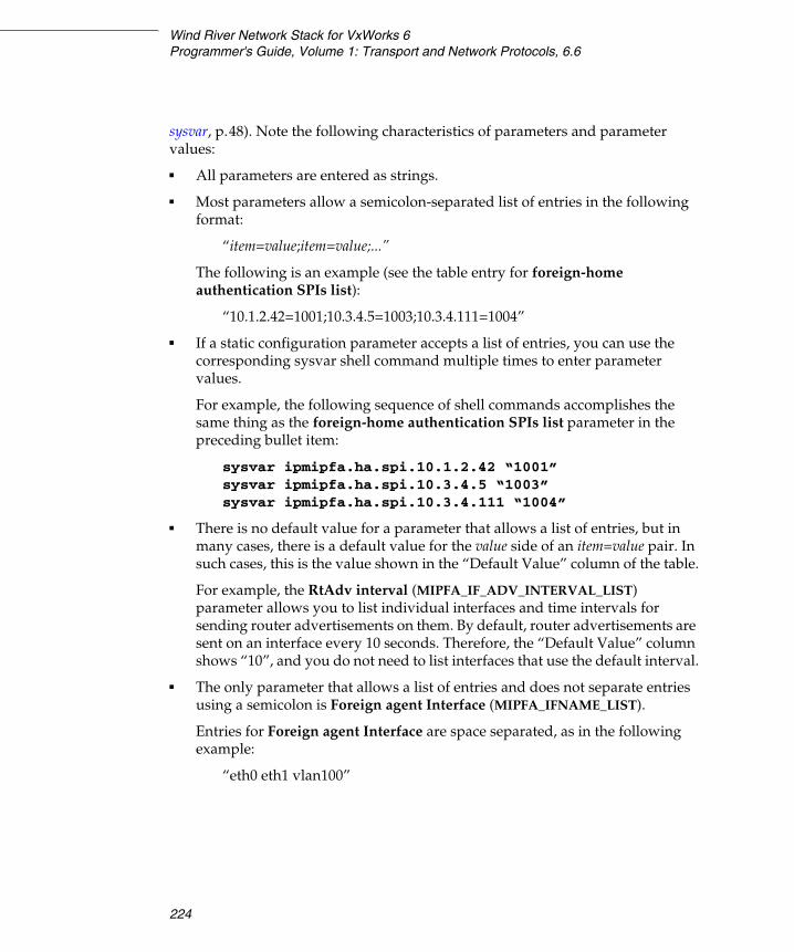
Wind River Network Stack for VxWorks 6Programmer's Guide, Volume 1: Transport and Network Protocols, 6.6
224
sysvar, p.48). Note the following characteristics of parameters and parameter values:
■ All parameters are entered as strings.
■ Most parameters allow a semicolon-separated list of entries in the following format:
“item=value;item=value;...”
The following is an example (see the table entry for foreign-home authentication SPIs list):
“10.1.2.42=1001;10.3.4.5=1003;10.3.4.111=1004”
■ If a static configuration parameter accepts a list of entries, you can use the corresponding sysvar shell command multiple times to enter parameter values.
For example, the following sequence of shell commands accomplishes the same thing as the foreign-home authentication SPIs list parameter in the preceding bullet item:
sysvar ipmipfa.ha.spi.10.1.2.42 “1001”sysvar ipmipfa.ha.spi.10.3.4.5 “1003”sysvar ipmipfa.ha.spi.10.3.4.111 “1004”
■ There is no default value for a parameter that allows a list of entries, but in many cases, there is a default value for the value side of an item=value pair. In such cases, this is the value shown in the “Default Value” column of the table.
For example, the RtAdv interval (MIPFA_IF_ADV_INTERVAL_LIST) parameter allows you to list individual interfaces and time intervals for sending router advertisements on them. By default, router advertisements are sent on an interface every 10 seconds. Therefore, the “Default Value” column shows “10”, and you do not need to list interfaces that use the default interval.
■ The only parameter that allows a list of entries and does not separate entries using a semicolon is Foreign agent Interface (MIPFA_IFNAME_LIST).
Entries for Foreign agent Interface are space separated, as in the following example:
“eth0 eth1 vlan100”
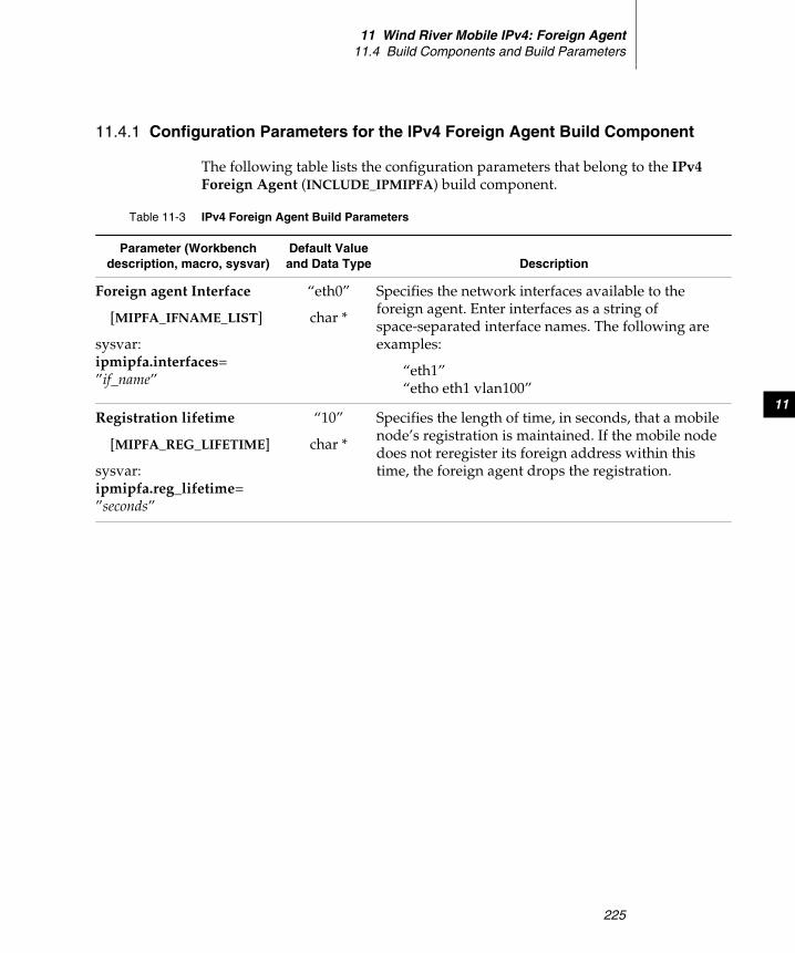
11 Wind River Mobile IPv4: Foreign Agent11.4 Build Components and Build Parameters
225
11
11.4.1 Configuration Parameters for the IPv4 Foreign Agent Build Component
The following table lists the configuration parameters that belong to the IPv4 Foreign Agent (INCLUDE_IPMIPFA) build component.
Table 11-3 IPv4 Foreign Agent Build Parameters
Parameter (Workbench description, macro, sysvar)
Default Value and Data Type Description
Foreign agent Interface
[MIPFA_IFNAME_LIST]
sysvar:ipmipfa.interfaces=”if_name”
“eth0”
char *
Specifies the network interfaces available to the foreign agent. Enter interfaces as a string of space-separated interface names. The following are examples:
“eth1”“etho eth1 vlan100”
Registration lifetime
[MIPFA_REG_LIFETIME]
sysvar:ipmipfa.reg_lifetime=”seconds”
“10”
char *
Specifies the length of time, in seconds, that a mobile node’s registration is maintained. If the mobile node does not reregister its foreign address within this time, the foreign agent drops the registration.

Wind River Network Stack for VxWorks 6Programmer's Guide, Volume 1: Transport and Network Protocols, 6.6
226
Foreign - Home security association list
[MIPFA_HA_SA_ADDRESS_LIST]
sysvar:ipmipfa.ha.sa.address.network[/prefix]= spi
[None]
char *
Specifies the security associations to use between the foreign agent and a home agent, in the following format:
“ha_address[/prefix]=SPI;ha_address[/prefix]=SPI;...”
If ha_address is set to any, the specified SPI applies to all home agents.
Examples
■ The following setting enables authentication using SPI 1002 between this foreign agent and the home agent with IP address 10.1.2.42:
"10.1.2.42=1002"
■ The following enables authentication using SPI 1002 between this foreign agent and all home agents:
"any=1002"
■ The following specifies that all home agents on the 10.1.2.0/24 network are to use SPI 1004.
"10.1.2.0/24=1004"
Foreign - Home security association reverse lookup
[MIPFA_HA_SA_LOOKUP_REQUIRE]
sysvar:ipmipfa.ha.sa.lookup.required=0_or_1
“0”
char
If set to “1”, requires the foreign agent to reverse lookup the SPI a home agent presents for use and verify that it is correct.
Table 11-3 IPv4 Foreign Agent Build Parameters (cont’d)
Parameter (Workbench description, macro, sysvar)
Default Value and Data Type Description
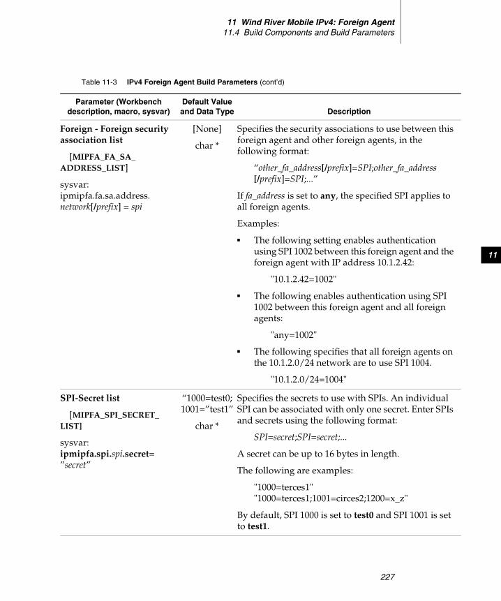
11 Wind River Mobile IPv4: Foreign Agent11.4 Build Components and Build Parameters
227
11
Foreign - Foreign security association list
[MIPFA_FA_SA_ADDRESS_LIST]
sysvar:ipmipfa.fa.sa.address.network[/prefix] = spi
[None]
char *
Specifies the security associations to use between this foreign agent and other foreign agents, in the following format:
“other_fa_address[/prefix]=SPI;other_fa_address[/prefix]=SPI;...”
If fa_address is set to any, the specified SPI applies to all foreign agents.
Examples:
■ The following setting enables authentication using SPI 1002 between this foreign agent and the foreign agent with IP address 10.1.2.42:
"10.1.2.42=1002"
■ The following enables authentication using SPI 1002 between this foreign agent and all foreign agents:
"any=1002"
■ The following specifies that all foreign agents on the 10.1.2.0/24 network are to use SPI 1004.
"10.1.2.0/24=1004"
SPI-Secret list
[MIPFA_SPI_SECRET_LIST]
sysvar:ipmipfa.spi.spi.secret=”secret”
“1000=test0;1001=”test1”
char *
Specifies the secrets to use with SPIs. An individual SPI can be associated with only one secret. Enter SPIs and secrets using the following format:
SPI=secret;SPI=secret;...
A secret can be up to 16 bytes in length.
The following are examples:
"1000=terces1""1000=terces1;1001=circes2;1200=x_z"
By default, SPI 1000 is set to test0 and SPI 1001 is set to test1.
Table 11-3 IPv4 Foreign Agent Build Parameters (cont’d)
Parameter (Workbench description, macro, sysvar)
Default Value and Data Type Description
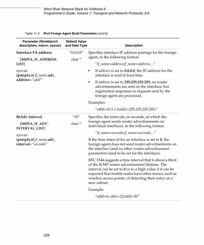
Wind River Network Stack for VxWorks 6Programmer's Guide, Volume 1: Transport and Network Protocols, 6.6
228
Interface FA address
[MIPFA_IF_ADDRESS_LIST]
sysvar:ipmipfa.if.if_name.adv_address=”addr”
“0.0.0.0”
char *
Specifies interface-IP address pairings for the foreign agent, in the following format:
“if_name=address;if_name=address;...”
■ If address is set to 0.0.0.0, the IP address for the interface is read at boot time.
■ If address is set to 255.255.255.255, no router advertisements are sent on the interface, but registration responses to requests sent by the foreign agent are processed.
Examples:
“eth0=10.1.1.5;eth1=255.255.255.255;”
RtAdv interval
[MIPFA_IF_ADV_INTERVAL_LIST]
sysvar:ipmipfa.if.if_name.adv_interval=”seconds”
“10”
char *
Specifies the intervals, in seconds, at which the foreign agent sends router advertisements on individual interfaces, in the following format:
“if_name=seconds;if_name=seconds;...”
If the time interval for an interface is set to 0, the foreign agent does not send router advertisements on the interface (and no other router-advertisement parameters need to be set for the interface).
RFC 3344 suggests a time interval that is about a third of the ICMP router advertisement lifetime. The interval can be set to 0 or to a high value if it can be expected that mobile nodes have other means, such as wireless access points, of detecting their entry on a new subnet.
Example:
“eth0=6; eth1=12;eth2=30”
Table 11-3 IPv4 Foreign Agent Build Parameters (cont’d)
Parameter (Workbench description, macro, sysvar)
Default Value and Data Type Description
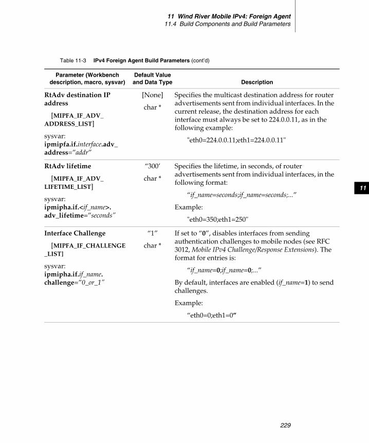
11 Wind River Mobile IPv4: Foreign Agent11.4 Build Components and Build Parameters
229
11
RtAdv destination IP address
[MIPFA_IF_ADV_ADDRESS_LIST]
sysvar:ipmipfa.if.interface.adv_address=”addr”
[None]
char *
Specifies the multicast destination address for router advertisements sent from individual interfaces. In the current release, the destination address for each interface must always be set to 224.0.0.11, as in the following example:
"eth0=224.0.0.11;eth1=224.0.0.11"
RtAdv lifetime
[MIPFA_IF_ADV_LIFETIME_LIST]
sysvar:ipmipha.if.<if_name>.adv_lifetime=”seconds”
“300’
char *
Specifies the lifetime, in seconds, of router advertisements sent from individual interfaces, in the following format:
“if_name=seconds;if_name=seconds;...”
Example:
"eth0=350;eth1=250"
Interface Challenge
[MIPFA_IF_CHALLENGE_LIST]
sysvar:ipmipha.if.if_name.challenge=”0_or_1”
“1”
char *
If set to “0”, disables interfaces from sending authentication challenges to mobile nodes (see RFC 3012, Mobile IPv4 Challenge/Response Extensions). The format for entries is:
“if_name=0;if_name=0;...”
By default, interfaces are enabled (if_name=1) to send challenges.
Example:
“eth0=0;eth1=0”
Table 11-3 IPv4 Foreign Agent Build Parameters (cont’d)
Parameter (Workbench description, macro, sysvar)
Default Value and Data Type Description
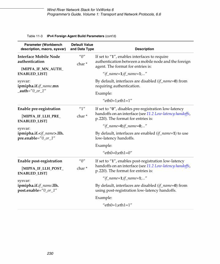
Wind River Network Stack for VxWorks 6Programmer's Guide, Volume 1: Transport and Network Protocols, 6.6
230
Interface Mobile Node authentication
[MIPFA_IF_MN_AUTH_ENABLED_LIST]
sysvar:ipmipha.if.if_name.mn_auth=”0_or_1”
“0”
char *
If set to “1”, enables interfaces to require authentication between a mobile node and the foreign agent. The format for entries is:
“if_name=1;if_name=1;...”
By default, interfaces are disabled (if_name=0) from requiring authentication.
Example:
“eth0=1;eth1=1”
Enable pre-registration
[MIPFA_IF_LLH_PRE_ENABLED_LIST]
sysvar:ipmipha.if.<if_name>.llh.pre.enable=”0_or_1”
“1”
char *
If set to “0”, disables pre-registration low-latency handoffs on an interface (see 11.2 Low-latency handoffs, p.220). The format for entries is:
“if_name=0;if_name=0;...”
By default, interfaces are enabled (if_name=1) to use low-latency handoffs.
Example:
“eth0=0;eth1=0”
Enable post-registration
[MIPFA_IF_LLH_POST_ENABLED_LIST]
sysvar:ipmipha.if.if_name.llh.post.enable=”0_or_1”
“0”
char *
If set to “1”, enables post-registration low-latency handoffs on an interface (see 11.2 Low-latency handoffs, p.220). The format for entries is:
“if_name=1;if_name=1;...”
By default, interfaces are disabled (if_name=0) from using post-registration low-latency handoffs.
Example:
“eth0=1;eth1=1”
Table 11-3 IPv4 Foreign Agent Build Parameters (cont’d)
Parameter (Workbench description, macro, sysvar)
Default Value and Data Type Description
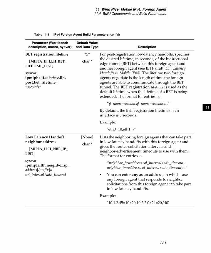
11 Wind River Mobile IPv4: Foreign Agent11.4 Build Components and Build Parameters
231
11
BET registration lifetime
[MIPFA_IF_LLH_BET_LIFETIME_LIST]
sysvar:ipmipha.if.interface.llh.post.bet_lifetime=”seconds”
“5”
char *
For post-registration low-latency handoffs, specifies the desired lifetime, in seconds, of the bidirectional edge tunnel (BET) between this foreign agent and another foreign agent (see IETF draft, Low Latency Handoffs in Mobile IPv4). The lifetime two foreign agents negotiate is the length of time the foreign agents are able to communicate through the BET tunnel. The BET registration lifetime is used as the default lifetime when the lifetime of a BET is being extended. The format for entries is:
“if_name=seconds;if_name=seconds;...”
By default, the BET registration lifetime on an interface is 5 seconds.
Example:
"eth0=10;eth1=7"
Low Latency Handoff neighbor address
[MIPFA_LLH_NBR_IP_LIST]
sysvar:ipmipfa.llh.neighbor.ip.address[/prefix]= sol_interval/adv_timeout
[None]
char *
Lists the neighboring foreign agents that can take part in low-latency handoffs with this foreign agent and gives the router-solicitation intervals and neighbor-advertisement timeouts to use with them. The format for entries is:
“neighbor_ip=address,sol_interval/adv_timeout;neighbor_ip=address,sol_interval/adv_timeout;...”
■ You can enter any as an address, in which case any foreign agent that responds to neighbor solicitations from this foreign agent can take part in low-latency handoffs.
Example:
"10.1.2.45=10/20;10.2.2.0/24=20/40"
Table 11-3 IPv4 Foreign Agent Build Parameters (cont’d)
Parameter (Workbench description, macro, sysvar)
Default Value and Data Type Description
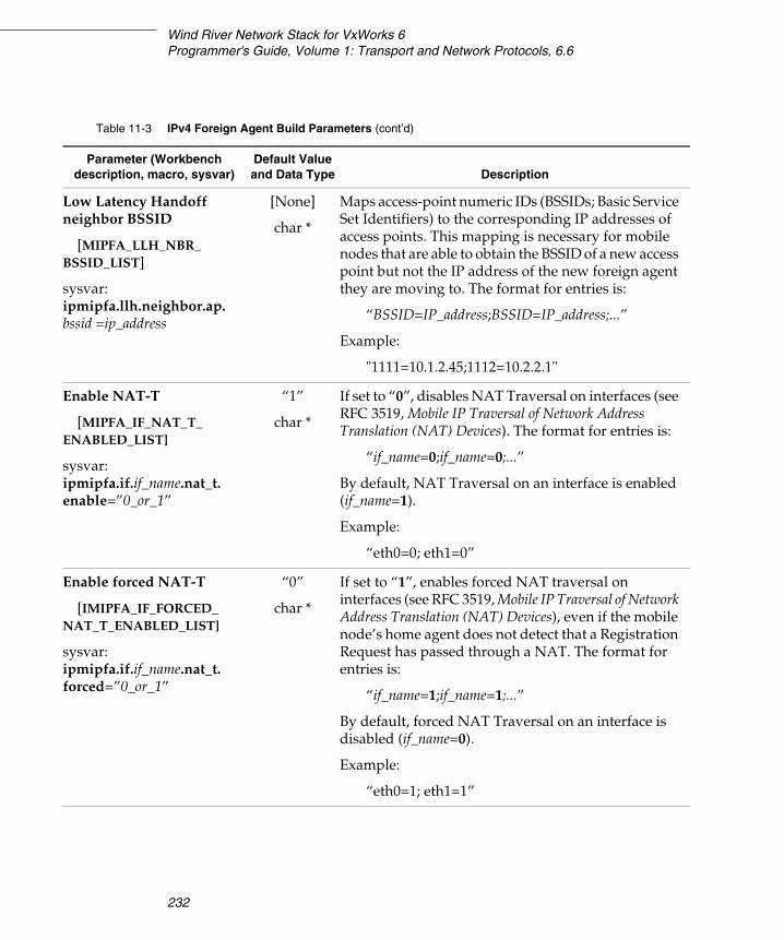
Wind River Network Stack for VxWorks 6Programmer's Guide, Volume 1: Transport and Network Protocols, 6.6
232
Low Latency Handoff neighbor BSSID
[MIPFA_LLH_NBR_BSSID_LIST]
sysvar:ipmipfa.llh.neighbor.ap.bssid =ip_address
[None]
char *
Maps access-point numeric IDs (BSSIDs; Basic Service Set Identifiers) to the corresponding IP addresses of access points. This mapping is necessary for mobile nodes that are able to obtain the BSSID of a new access point but not the IP address of the new foreign agent they are moving to. The format for entries is:
“BSSID=IP_address;BSSID=IP_address;...”
Example:
"1111=10.1.2.45;1112=10.2.2.1"
Enable NAT-T
[MIPFA_IF_NAT_T_ENABLED_LIST]
sysvar:ipmipfa.if.if_name.nat_t.enable=”0_or_1”
“1”
char *
If set to “0”, disables NAT Traversal on interfaces (see RFC 3519, Mobile IP Traversal of Network Address Translation (NAT) Devices). The format for entries is:
“if_name=0;if_name=0;...”
By default, NAT Traversal on an interface is enabled (if_name=1).
Example:
“eth0=0; eth1=0”
Enable forced NAT-T
[IMIPFA_IF_FORCED_NAT_T_ENABLED_LIST]
sysvar:ipmipfa.if.if_name.nat_t.forced=”0_or_1”
“0”
char *
If set to “1”, enables forced NAT traversal on interfaces (see RFC 3519, Mobile IP Traversal of Network Address Translation (NAT) Devices), even if the mobile node’s home agent does not detect that a Registration Request has passed through a NAT. The format for entries is:
“if_name=1;if_name=1;...”
By default, forced NAT Traversal on an interface is disabled (if_name=0).
Example:
“eth0=1; eth1=1”
Table 11-3 IPv4 Foreign Agent Build Parameters (cont’d)
Parameter (Workbench description, macro, sysvar)
Default Value and Data Type Description
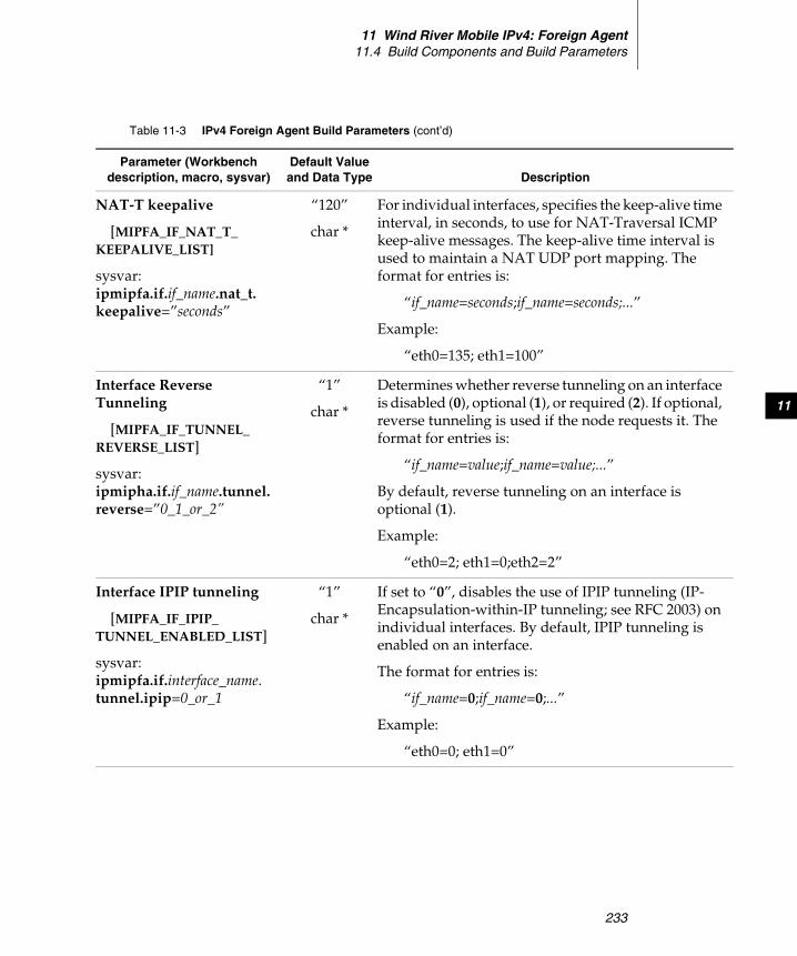
11 Wind River Mobile IPv4: Foreign Agent11.4 Build Components and Build Parameters
233
11
NAT-T keepalive
[MIPFA_IF_NAT_T_KEEPALIVE_LIST]
sysvar:ipmipfa.if.if_name.nat_t.keepalive=”seconds”
“120”
char *
For individual interfaces, specifies the keep-alive time interval, in seconds, to use for NAT-Traversal ICMP keep-alive messages. The keep-alive time interval is used to maintain a NAT UDP port mapping. The format for entries is:
“if_name=seconds;if_name=seconds;...”
Example:
“eth0=135; eth1=100”
Interface Reverse Tunneling
[MIPFA_IF_TUNNEL_REVERSE_LIST]
sysvar:ipmipha.if.if_name.tunnel.reverse=”0_1_or_2”
“1”
char *
Determines whether reverse tunneling on an interface is disabled (0), optional (1), or required (2). If optional, reverse tunneling is used if the node requests it. The format for entries is:
“if_name=value;if_name=value;...”
By default, reverse tunneling on an interface is optional (1).
Example:
“eth0=2; eth1=0;eth2=2”
Interface IPIP tunneling
[MIPFA_IF_IPIP_TUNNEL_ENABLED_LIST]
sysvar:ipmipfa.if.interface_name.tunnel.ipip=0_or_1
“1”
char *
If set to “0”, disables the use of IPIP tunneling (IP- Encapsulation-within-IP tunneling; see RFC 2003) on individual interfaces. By default, IPIP tunneling is enabled on an interface.
The format for entries is:
“if_name=0;if_name=0;...”
Example:
“eth0=0; eth1=0”
Table 11-3 IPv4 Foreign Agent Build Parameters (cont’d)
Parameter (Workbench description, macro, sysvar)
Default Value and Data Type Description
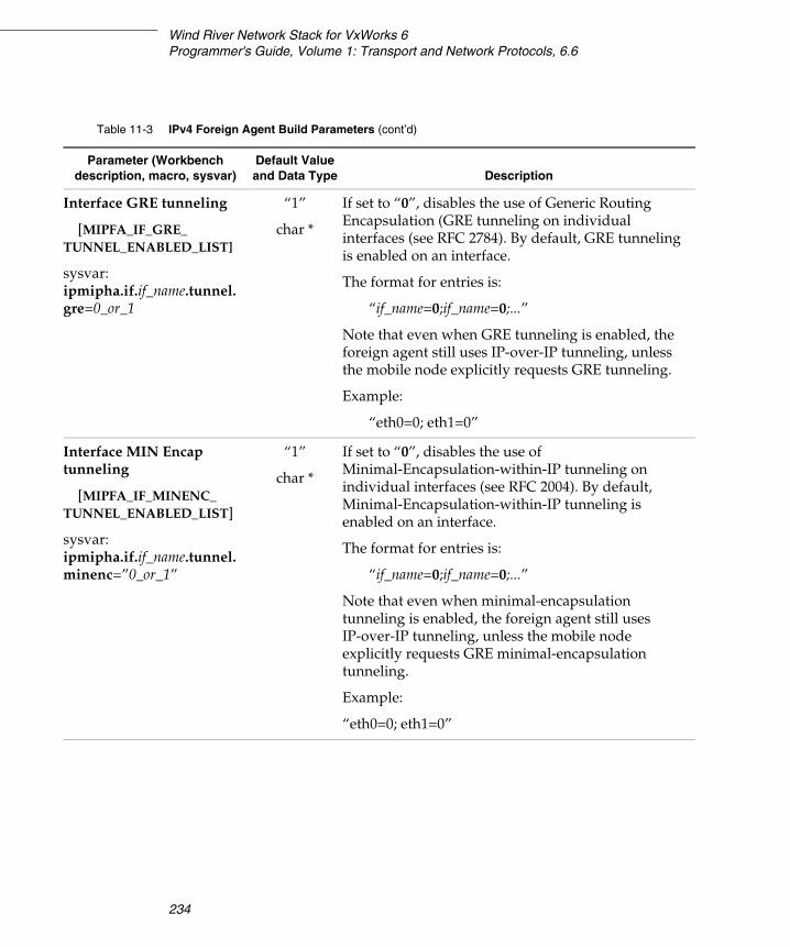
Wind River Network Stack for VxWorks 6Programmer's Guide, Volume 1: Transport and Network Protocols, 6.6
234
Interface GRE tunneling
[MIPFA_IF_GRE_TUNNEL_ENABLED_LIST]
sysvar:ipmipha.if.if_name.tunnel.gre=0_or_1
“1”
char *
If set to “0”, disables the use of Generic Routing Encapsulation (GRE tunneling on individual interfaces (see RFC 2784). By default, GRE tunneling is enabled on an interface.
The format for entries is:
“if_name=0;if_name=0;...”
Note that even when GRE tunneling is enabled, the foreign agent still uses IP-over-IP tunneling, unless the mobile node explicitly requests GRE tunneling.
Example:
“eth0=0; eth1=0”
Interface MIN Encap tunneling
[MIPFA_IF_MINENC_TUNNEL_ENABLED_LIST]
sysvar:ipmipha.if.if_name.tunnel.minenc=”0_or_1”
“1”
char *
If set to “0”, disables the use of Minimal-Encapsulation-within-IP tunneling on individual interfaces (see RFC 2004). By default, Minimal-Encapsulation-within-IP tunneling is enabled on an interface.
The format for entries is:
“if_name=0;if_name=0;...”
Note that even when minimal-encapsulation tunneling is enabled, the foreign agent still uses IP-over-IP tunneling, unless the mobile node explicitly requests GRE minimal-encapsulation tunneling.
Example:
“eth0=0; eth1=0”
Table 11-3 IPv4 Foreign Agent Build Parameters (cont’d)
Parameter (Workbench description, macro, sysvar)
Default Value and Data Type Description
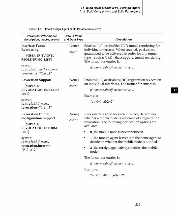
11 Wind River Mobile IPv4: Foreign Agent11.4 Build Components and Build Parameters
235
11
Interface Tunnel Reordering
[MIPFA_IF_TUNNEL_REORDERING_LIST]
sysvar:ipmipfa.if.interface_name.reordering=”0_or_1”
[None]
char *
Enables (“1”) or disables (“0”) tunnel reordering for individual interfaces. When enabled, packets are guaranteed to be delivered in order for any tunnel type—such as GRE—that supports tunnel reordering. The format for entries is:
if_name=value;if_name=value;...
Revocation Support
[MIPFA_IF_REVOCATION_ENABLED_LIST]
sysvar:ipmipfa.if.if_name.revocation=”0_or_1”
[None]
char *
Enables (“1”) or disables (“0”) registration revocation on individual interfaces. The format for entries is:
if_name=value;if_name=value;...
Example:
“eth0=1;eth2=2”
Revocation Inform configuration Support
[MIPFA_IF_REVOCATION_INFORM_LIST]
sysvar:ipmipfa.if.if_name.revocation.inform=”0_1_or_2”
[None]
char *
Lists interfaces and for each interface, determines whether a mobile node is informed of a registration revocation. The following notification options are available:
■ 0 (the mobile node is never notified)
■ 1 (the foreign agent leaves it to the home agent to decide on whether the mobile node is notified)
■ 2 (the foreign agent always notifies the mobile node)
The format for entries is:
if_name=value;if_name=value;...
Example:
“eth0=1;eth1=0;eth3=2”
Table 11-3 IPv4 Foreign Agent Build Parameters (cont’d)
Parameter (Workbench description, macro, sysvar)
Default Value and Data Type Description
Wind River Network Stack for VxWorks 6Programmer's Guide, Volume 1: Transport and Network Protocols, 6.6
236
11.4.2 Configuration Parameters for RADIUS Support
The following table lists the configuration parameters that belong to the IPv4 Foreign Agent AAA Radius Support (INCLUDE_IPMIPFA_AAA_RADIUS) build component.
Table 11-4 IPv4 Foreign Agent AAA Radius Build Parameters
Parameter(Workbench, Macro, Sysvar)
Default Value and Data Type Description
RADIUS Access Support
[MIPFA_AAA_RADIUS_ACCESS]
sysvar:ipmipfa.aaa.radius.access=”0_or_1”
"disabled"
char *
If set to “enabled”, the foreign agent uses RADIUS. By default, RADIUS is not used.
RADIUS Access server address
[MIPFA_AAA_RADIUS_ACCESS_ADDRESS]
sysvar:ipmipfa.aaa.radius.access.address=”radius_server_address”
[None]
char *
The IP address of the RADIUS server to send access requests to.
RADIUS Access server port
[MIPFA_AAA_RADIUS_ACCESS_PORT]
sysvar:ipmipfa.aaa.radius.access.port=”radius_server_port”
"1812"
char *
The port on the RADIUS server to send access requests to.
11 Wind River Mobile IPv4: Foreign Agent11.4 Build Components and Build Parameters
237
11
RADIUS Access server secret
[MIPFA_AAA_RADIUS_ACCESS_SECRET]
sysvar:ipmipfa.aaa.radius.access.secret=”secret”
[None]
char *
The security secret to send to the RADIUS server for enabling communication between the RADIUS server and the foreign agent.
RADIUS Access Required
[MIPFA_AAA_RADIUS_ACCESS_REQUIRE]
sysvar:ipmipfa.aaa.radius.access.require=”true_or_false”
"false"
char *
If set to “true”, the mobile-node must use RADIUS and include an MN-AAA authentication extension in its registration request to the foreign agent. For information on how a mobile-node authenticates itself to a foreign agent using RADIUS, see RFC 4721, Mobile IPv4 Challenge/Response Extensions (Revised), which is a revision of RFC 3012.
RADIUS Access Interval
[MIPFA_AAA_RADIUS_ACCESS_TIME_INTERVAL]
sysvar:
ipmipfa.aaa.radius.access.time_interval=0_or_1
“0” If set to “0”, the default, the foreign agent needs to renew its authentication with the RADIUS server every time it receives authentication credentials (such as an MN-AAA authentication extension) from a mobile node.
If a number greater than zero is entered, it sets the time-interval, in seconds, after which the foreign agent needs to renew its AAA authentication with the RADIUS server. If the mobile node sends repeated authentication credentials to the foreign agent, the foreign agent does not need to reauthenticate itself to the RADIUS server until the specified time interval has elapsed.
Table 11-4 IPv4 Foreign Agent AAA Radius Build Parameters (cont’d)
Parameter(Workbench, Macro, Sysvar)
Default Value and Data Type Description

Wind River Network Stack for VxWorks 6Programmer's Guide, Volume 1: Transport and Network Protocols, 6.6
238
RADIUS Accounting Support
[MIPFA_AAA_RADIUS_ACCOUNTING]
sysvar:ipmipfa.aaa.radius.accounting=”0_or_1”
"disabled"
char *
If set to “enabled”, the foreign agent provides accounting information about the mobile node to a RADIUS server.
RADIUS Accounting server address
[MIPFA_AAA_RADIUS_ACCOUNTING_ADDRESS]
sysvar:ipmipfa.aaa.radius.accounting.address=“ip_address”
[None]
char *
The address of the RADIUS server to send accounting information to.
RADIUS Accounting server port
[MIPFA_AAA_RADIUS_ACCOUNTING_PORT]
sysvar:ipmipfa.aaa.radius.accounting.port=”port”
"1813"
char *
The port to send RADIUS accounting information to.
RADIUS Accounting server secret
[MIPFA_AAA_RADIUS_ACCOUNTING_SECRET]
sysvar:ipmipfa.aaa.radius.accounting.sec=”secret”
[None]
char *
The security secret to send to the RADIUS server for accounting in order to enable communication between the server and the foreign agent.
Table 11-4 IPv4 Foreign Agent AAA Radius Build Parameters (cont’d)
Parameter(Workbench, Macro, Sysvar)
Default Value and Data Type Description
11 Wind River Mobile IPv4: Foreign Agent11.4 Build Components and Build Parameters
239
11
11.4.3 Configuration Parameters for Diameter Support
Diameter is an enhanced AAA protocol based on RADIUS. It is described in RFC 3588, Diameter Base Protocol.
The following table lists the configuration parameters that belong to the IPv4 Foreign Agent AAA DIAMETER Support (INCLUDE_IPMIPFA_AAA_DIAMETER) build component.
RADIUS local address
[MIPFA_AAA_RADIUS_LOCAL_ADDRESS]
sysvar:ipmipfa.aaa.radius.local.address=”local_address”
[None]
char *
The IP address the foreign agent uses for all communication with a RADIUS server.
Table 11-4 IPv4 Foreign Agent AAA Radius Build Parameters (cont’d)
Parameter(Workbench, Macro, Sysvar)
Default Value and Data Type Description
Table 11-5 IPv4 Foreign Agent AAA DIAMETER Build Parameters
Parameter (Workbench description, macro, sysvar)
Default Value and Data Type Description
Diameter Access Support
[MIPFA_AAA_DIAMETER_ACCESS]
sysvar:ipmipfa.aaa.diameter.access=”0_or_1”
"disabled"
char *
If set to “enabled”, the foreign agent uses DIAMETER. By default, DIAMETER is not used.
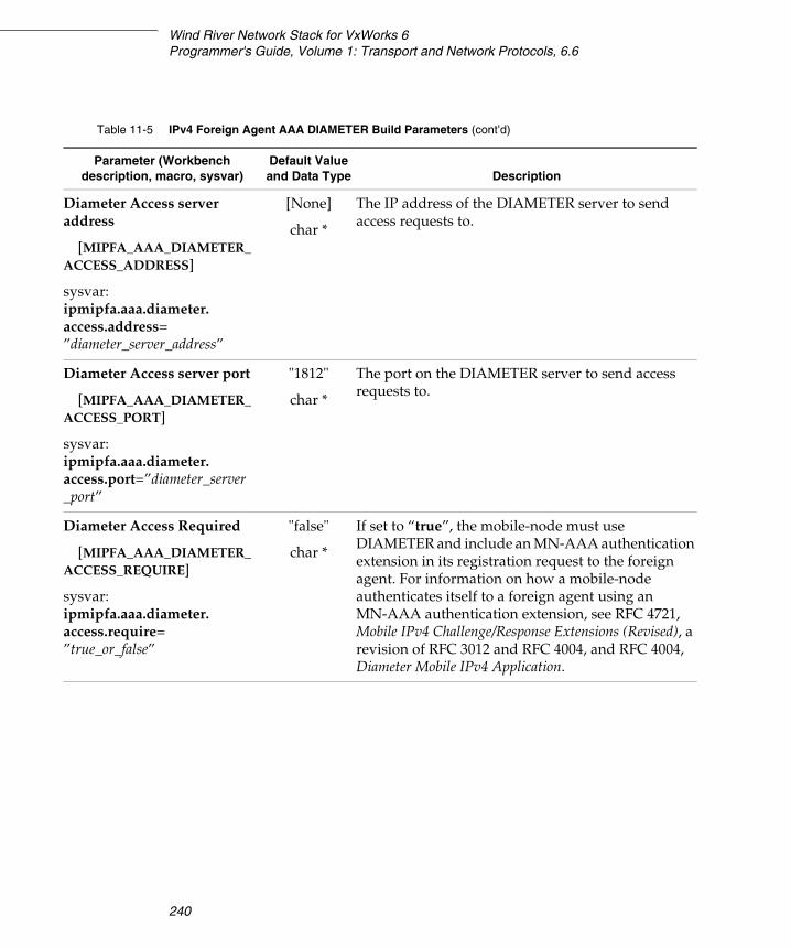
Wind River Network Stack for VxWorks 6Programmer's Guide, Volume 1: Transport and Network Protocols, 6.6
240
Diameter Access server address
[MIPFA_AAA_DIAMETER_ACCESS_ADDRESS]
sysvar:ipmipfa.aaa.diameter.access.address=”diameter_server_address”
[None]
char *
The IP address of the DIAMETER server to send access requests to.
Diameter Access server port
[MIPFA_AAA_DIAMETER_ACCESS_PORT]
sysvar:ipmipfa.aaa.diameter.access.port=”diameter_server_port”
"1812"
char *
The port on the DIAMETER server to send access requests to.
Diameter Access Required
[MIPFA_AAA_DIAMETER_ACCESS_REQUIRE]
sysvar:ipmipfa.aaa.diameter.access.require=”true_or_false”
"false"
char *
If set to “true”, the mobile-node must use DIAMETER and include an MN-AAA authentication extension in its registration request to the foreign agent. For information on how a mobile-node authenticates itself to a foreign agent using an MN-AAA authentication extension, see RFC 4721, Mobile IPv4 Challenge/Response Extensions (Revised), a revision of RFC 3012 and RFC 4004, and RFC 4004, Diameter Mobile IPv4 Application.
Table 11-5 IPv4 Foreign Agent AAA DIAMETER Build Parameters (cont’d)
Parameter (Workbench description, macro, sysvar)
Default Value and Data Type Description
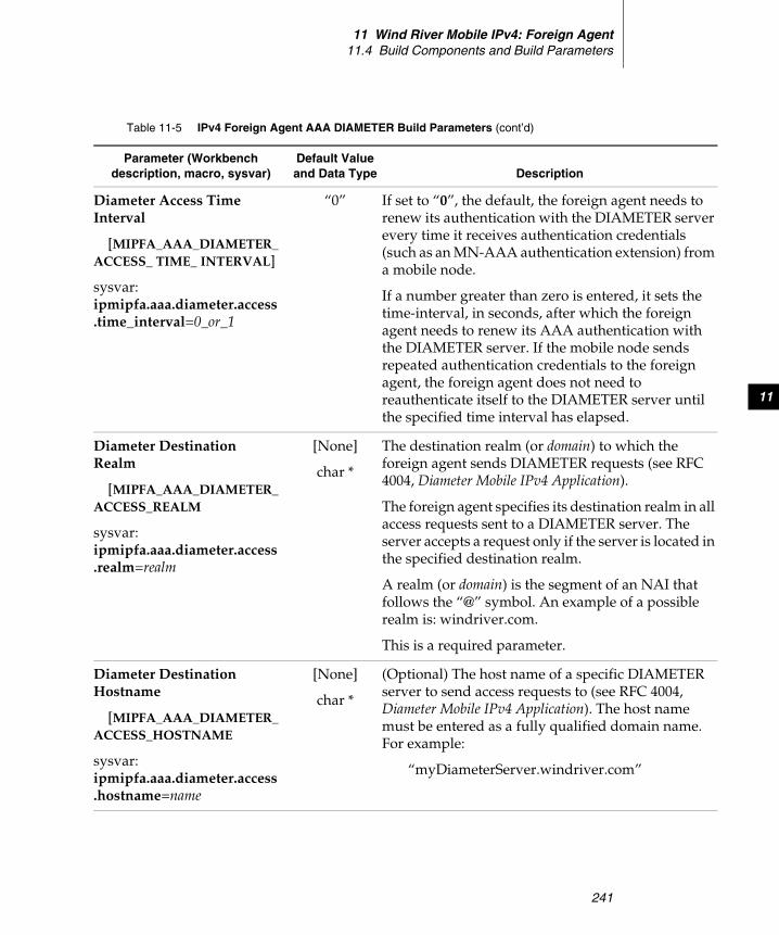
11 Wind River Mobile IPv4: Foreign Agent11.4 Build Components and Build Parameters
241
11
Diameter Access Time Interval
[MIPFA_AAA_DIAMETER_ACCESS_ TIME_ INTERVAL]
sysvar:ipmipfa.aaa.diameter.access.time_interval=0_or_1
“0” If set to “0”, the default, the foreign agent needs to renew its authentication with the DIAMETER server every time it receives authentication credentials (such as an MN-AAA authentication extension) from a mobile node.
If a number greater than zero is entered, it sets the time-interval, in seconds, after which the foreign agent needs to renew its AAA authentication with the DIAMETER server. If the mobile node sends repeated authentication credentials to the foreign agent, the foreign agent does not need to reauthenticate itself to the DIAMETER server until the specified time interval has elapsed.
Diameter Destination Realm
[MIPFA_AAA_DIAMETER_ACCESS_REALM
sysvar:ipmipfa.aaa.diameter.access.realm=realm
[None]
char *
The destination realm (or domain) to which the foreign agent sends DIAMETER requests (see RFC 4004, Diameter Mobile IPv4 Application).
The foreign agent specifies its destination realm in all access requests sent to a DIAMETER server. The server accepts a request only if the server is located in the specified destination realm.
A realm (or domain) is the segment of an NAI that follows the “@” symbol. An example of a possible realm is: windriver.com.
This is a required parameter.
Diameter Destination Hostname
[MIPFA_AAA_DIAMETER_ACCESS_HOSTNAME
sysvar:ipmipfa.aaa.diameter.access.hostname=name
[None]
char *
(Optional) The host name of a specific DIAMETER server to send access requests to (see RFC 4004, Diameter Mobile IPv4 Application). The host name must be entered as a fully qualified domain name. For example:
“myDiameterServer.windriver.com”
Table 11-5 IPv4 Foreign Agent AAA DIAMETER Build Parameters (cont’d)
Parameter (Workbench description, macro, sysvar)
Default Value and Data Type Description
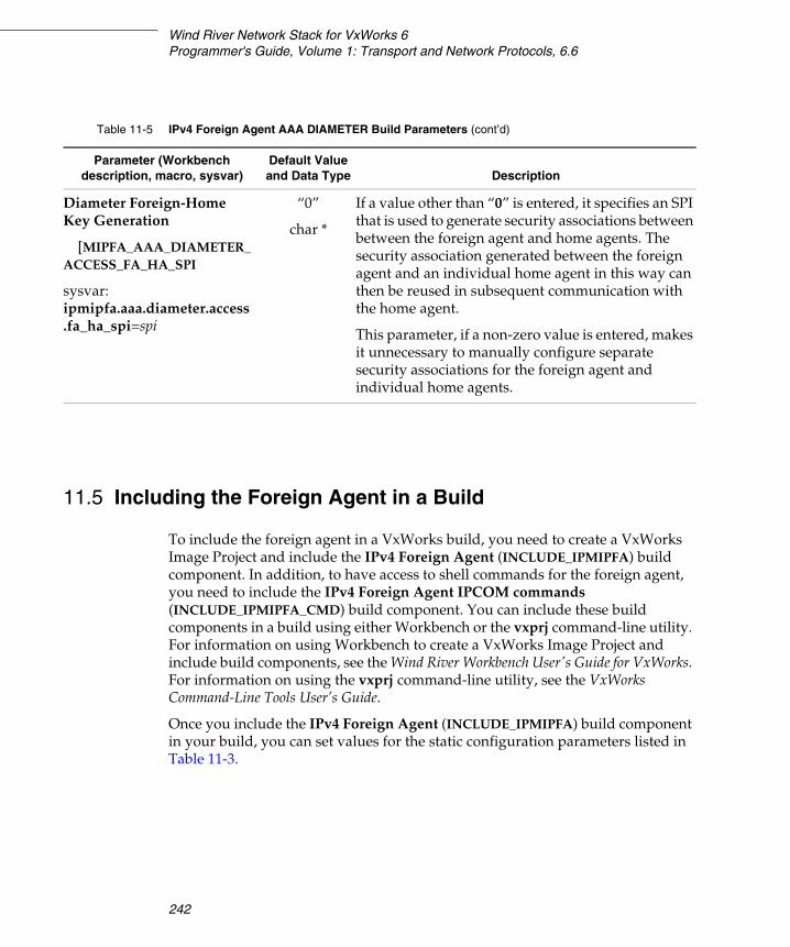
Wind River Network Stack for VxWorks 6Programmer's Guide, Volume 1: Transport and Network Protocols, 6.6
242
11.5 Including the Foreign Agent in a Build
To include the foreign agent in a VxWorks build, you need to create a VxWorks Image Project and include the IPv4 Foreign Agent (INCLUDE_IPMIPFA) build component. In addition, to have access to shell commands for the foreign agent, you need to include the IPv4 Foreign Agent IPCOM commands (INCLUDE_IPMIPFA_CMD) build component. You can include these build components in a build using either Workbench or the vxprj command-line utility. For information on using Workbench to create a VxWorks Image Project and include build components, see the Wind River Workbench User's Guide for VxWorks. For information on using the vxprj command-line utility, see the VxWorks Command-Line Tools User’s Guide.
Once you include the IPv4 Foreign Agent (INCLUDE_IPMIPFA) build component in your build, you can set values for the static configuration parameters listed in Table 11-3.
Diameter Foreign-Home Key Generation
[MIPFA_AAA_DIAMETER_ACCESS_FA_HA_SPI
sysvar:ipmipfa.aaa.diameter.access.fa_ha_spi=spi
“0”
char *
If a value other than “0” is entered, it specifies an SPI that is used to generate security associations between between the foreign agent and home agents. The security association generated between the foreign agent and an individual home agent in this way can then be reused in subsequent communication with the home agent.
This parameter, if a non-zero value is entered, makes it unnecessary to manually configure separate security associations for the foreign agent and individual home agents.
Table 11-5 IPv4 Foreign Agent AAA DIAMETER Build Parameters (cont’d)
Parameter (Workbench description, macro, sysvar)
Default Value and Data Type Description
11 Wind River Mobile IPv4: Foreign Agent11.6 Shell Commands
243
11
11.6 Shell Commands
You can use foreign-agent shell commands to display information about current mobile-node registrations and to list errors that have occurred at the foreign agent (see 11.6.1 Shell Commands for Displaying Registration and Error Information, p.243). In addition, for testing purposed, you can use shell commands to generate layer-2 triggers for low-latency handoffs (see 11.6.2 Shell Commands for Layer-2 Triggers, p.246).
11.6.1 Shell Commands for Displaying Registration and Error Information
Table 11-6 lists the foreign-agent shell commands for displaying status information about mobile-node registrations and for displaying errors information.
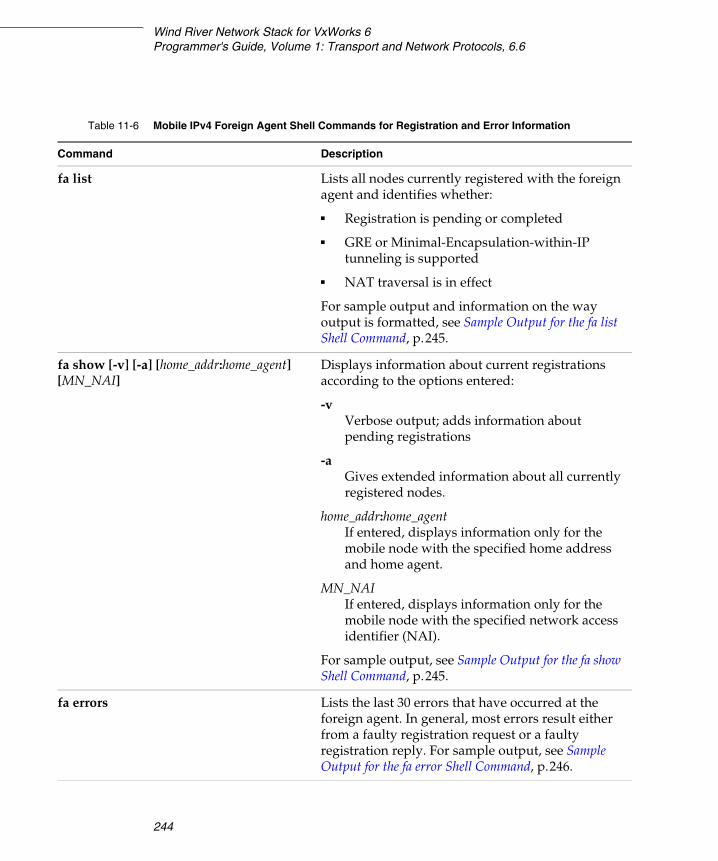
Wind River Network Stack for VxWorks 6Programmer's Guide, Volume 1: Transport and Network Protocols, 6.6
244
Table 11-6 Mobile IPv4 Foreign Agent Shell Commands for Registration and Error Information
Command Description
fa list Lists all nodes currently registered with the foreign agent and identifies whether:
■ Registration is pending or completed
■ GRE or Minimal-Encapsulation-within-IP tunneling is supported
■ NAT traversal is in effect
For sample output and information on the way output is formatted, see Sample Output for the fa list Shell Command, p.245.
fa show [-v] [-a] [home_addr:home_agent] [MN_NAI]
Displays information about current registrations according to the options entered:
-v Verbose output; adds information about pending registrations
-aGives extended information about all currently registered nodes.
home_addr:home_agentIf entered, displays information only for the mobile node with the specified home address and home agent.
MN_NAIIf entered, displays information only for the mobile node with the specified network access identifier (NAI).
For sample output, see Sample Output for the fa show Shell Command, p.245.
fa errors Lists the last 30 errors that have occurred at the foreign agent. In general, most errors result either from a faulty registration request or a faulty registration reply. For sample output, see Sample Output for the fa error Shell Command, p.246.

11 Wind River Mobile IPv4: Foreign Agent11.6 Shell Commands
245
11
Sample Output for the fa list Shell Command
The fa list shell command lists all nodes currently registered with the foreign agent and gives status information about pending and completed registrations, tunneling support, and whether NAT traversal is in effect. Status information is provided as follows:
The following is sample output:
>fa list Status Home Address Home Agent Interface Lifetime+ T 192.168.1.20 192.168.1.1 vlan11 26/30
Sample Output for the fa show Shell Command
The fa show shell command displays information about current registrations. The following is sample output:
>fa show -a192.168.1.20:192.168.1.1:Creation : Apr 19 09:03:02Mobile NAI : [email protected] : MAC:00:00:00:00:00:03Registration:Last updated : Apr 19 09:04:17Lifetime requested: 30Lifetime remaining: 22Reverse tunnel : yesInterface : vlan11Registration Type : normalTunnel type : IPIPNat traversal : no
Symbol Description
+ Completed registration.- Pending registration.G GRE tunneling supported.M Minimal Encapsulation within IP tunneling supported.T Reverse tunneling is in effect.* NAT Traversal is in effect.
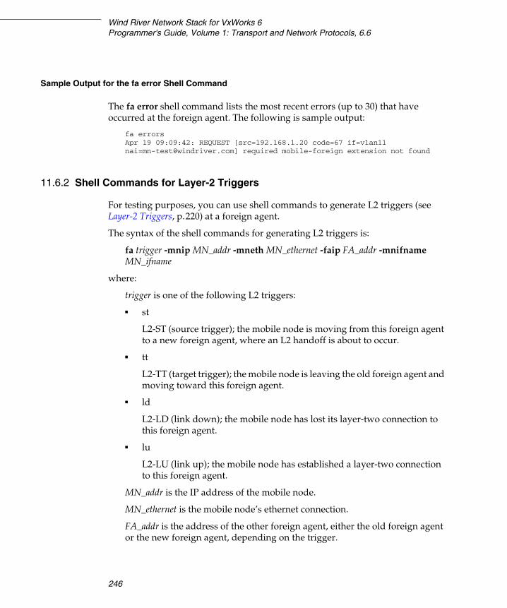
Wind River Network Stack for VxWorks 6Programmer's Guide, Volume 1: Transport and Network Protocols, 6.6
246
Sample Output for the fa error Shell Command
The fa error shell command lists the most recent errors (up to 30) that have occurred at the foreign agent. The following is sample output:
fa errorsApr 19 09:09:42: REQUEST [src=192.168.1.20 code=67 [email protected]] required mobile-foreign extension not found
11.6.2 Shell Commands for Layer-2 Triggers
For testing purposes, you can use shell commands to generate L2 triggers (see Layer-2 Triggers, p.220) at a foreign agent.
The syntax of the shell commands for generating L2 triggers is:
fa trigger -mnip MN_addr -mneth MN_ethernet -faip FA_addr -mnifname MN_ifname
where:
trigger is one of the following L2 triggers:
■ st
L2-ST (source trigger); the mobile node is moving from this foreign agent to a new foreign agent, where an L2 handoff is about to occur.
■ tt
L2-TT (target trigger); the mobile node is leaving the old foreign agent and moving toward this foreign agent.
■ ld
L2-LD (link down); the mobile node has lost its layer-two connection to this foreign agent.
■ lu
L2-LU (link up); the mobile node has established a layer-two connection to this foreign agent.
MN_addr is the IP address of the mobile node.
MN_ethernet is the mobile node’s ethernet connection.
FA_addr is the address of the other foreign agent, either the old foreign agent or the new foreign agent, depending on the trigger.
11 Wind River Mobile IPv4: Foreign Agent11.7 Testing the Foreign Agent
247
11
MN_ifname is the name of either the interface on the new foreign agent that the mobile node is moving to or the name of the interface on the old foreign agent that the mobile node is leaving, depending on the trigger.
11.7 Testing the Foreign Agent
This section provides an example showing how you can test the foreign agent. It requires the following components:
■ Home agent■ Mobile node■ Correspondent node■ A home network for the mobile node and home agent■ Foreign agent■ A foreign network for the foreign agent and the mobile node (when it is away
from home)■ A router
Figure 11-1 shows a test configuration with these elements and sample IP addresses:
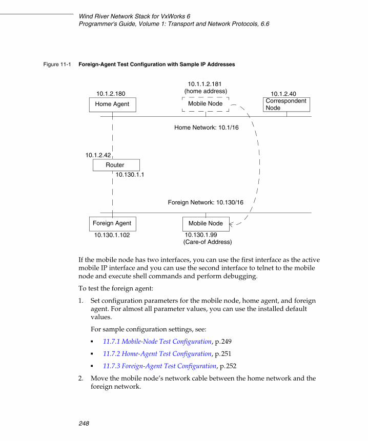
Wind River Network Stack for VxWorks 6Programmer's Guide, Volume 1: Transport and Network Protocols, 6.6
248
If the mobile node has two interfaces, you can use the first interface as the active mobile IP interface and you can use the second interface to telnet to the mobile node and execute shell commands and perform debugging.
To test the foreign agent:
1. Set configuration parameters for the mobile node, home agent, and foreign agent. For almost all parameter values, you can use the installed default values.
For sample configuration settings, see:
■ 11.7.1 Mobile-Node Test Configuration, p.249
■ 11.7.2 Home-Agent Test Configuration, p.251
■ 11.7.3 Foreign-Agent Test Configuration, p.252
2. Move the mobile node’s network cable between the home network and the foreign network.
Figure 11-1 Foreign-Agent Test Configuration with Sample IP Addresses
Router
Correspondent10.1.2.180
Node
Foreign Agent
Home Agent Mobile Node
10.1.1.2.181
10.1.2.40
Home Network: 10.1/16
(home address)
Mobile Node
Foreign Network: 10.130/16
10.130.1.102 10.130.1.99(Care-of Address)
10.1.2.42
10.130.1.1
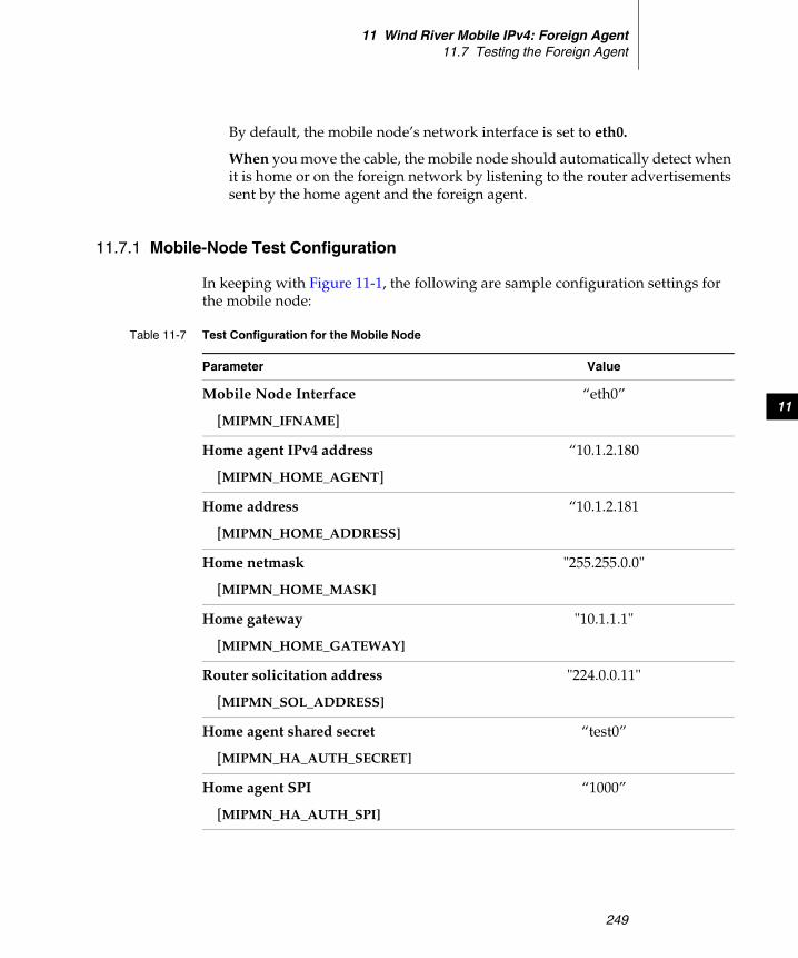
11 Wind River Mobile IPv4: Foreign Agent11.7 Testing the Foreign Agent
249
11
By default, the mobile node’s network interface is set to eth0.
When you move the cable, the mobile node should automatically detect when it is home or on the foreign network by listening to the router advertisements sent by the home agent and the foreign agent.
11.7.1 Mobile-Node Test Configuration
In keeping with Figure 11-1, the following are sample configuration settings for the mobile node:
Table 11-7 Test Configuration for the Mobile Node
Parameter Value
Mobile Node Interface
[MIPMN_IFNAME]
“eth0”
Home agent IPv4 address
[MIPMN_HOME_AGENT]
“10.1.2.180
Home address
[MIPMN_HOME_ADDRESS]
“10.1.2.181
Home netmask
[MIPMN_HOME_MASK]
"255.255.0.0"
Home gateway
[MIPMN_HOME_GATEWAY]
"10.1.1.1"
Router solicitation address
[MIPMN_SOL_ADDRESS]
"224.0.0.11"
Home agent shared secret
[MIPMN_HA_AUTH_SECRET]
“test0”
Home agent SPI
[MIPMN_HA_AUTH_SPI]
“1000”
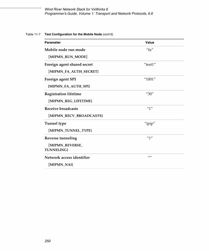
Wind River Network Stack for VxWorks 6Programmer's Guide, Volume 1: Transport and Network Protocols, 6.6
250
Mobile node run mode
[MIPMN_RUN_MODE]
“fa”
Foreign agent shared secret
[MIPMN_FA_AUTH_SECRET]
“test1”
Foreign agent SPI
[MIPMN_FA_AUTH_SPI]
“1001”
Registration lifetime
[MIPMN_REG_LIFETIME]
“30”
Receive broadcasts
[MIPMN_RECV_BROADCASTS]
“1”
Tunnel type
[MIPMN_TUNNEL_TYPE]
“ipip”
Reverse tunneling
[MIPMN_REVERSE_TUNNELING]
“1”
Network access identifier
[MIPMN_NAI]
““
Table 11-7 Test Configuration for the Mobile Node (cont’d)
Parameter Value
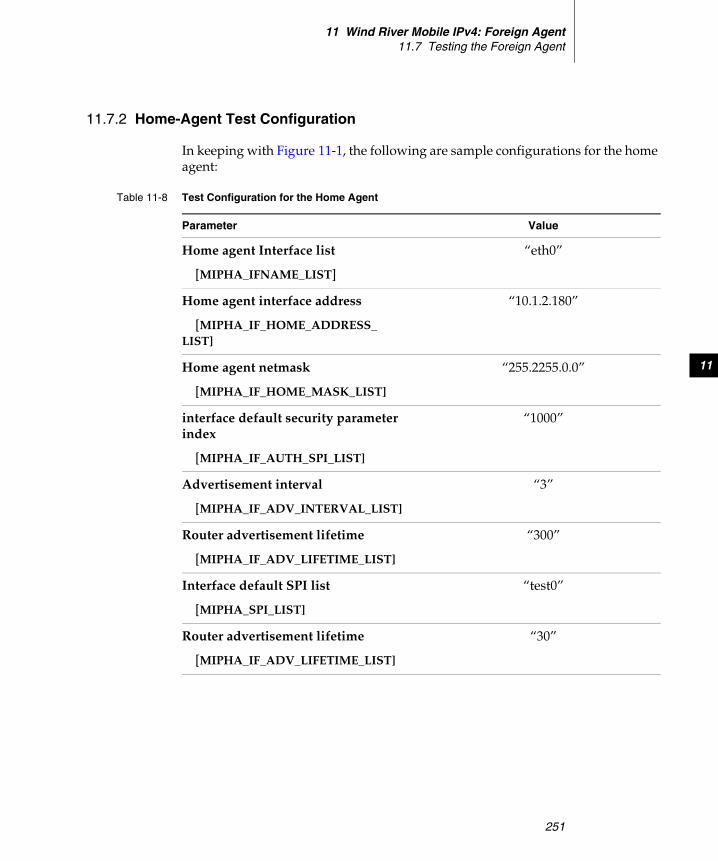
11 Wind River Mobile IPv4: Foreign Agent11.7 Testing the Foreign Agent
251
11
11.7.2 Home-Agent Test Configuration
In keeping with Figure 11-1, the following are sample configurations for the home agent:
Table 11-8 Test Configuration for the Home Agent
Parameter Value
Home agent Interface list
[MIPHA_IFNAME_LIST]
“eth0”
Home agent interface address
[MIPHA_IF_HOME_ADDRESS_LIST]
“10.1.2.180”
Home agent netmask
[MIPHA_IF_HOME_MASK_LIST]
“255.2255.0.0”
interface default security parameter index
[MIPHA_IF_AUTH_SPI_LIST]
“1000”
Advertisement interval
[MIPHA_IF_ADV_INTERVAL_LIST]
“3”
Router advertisement lifetime
[MIPHA_IF_ADV_LIFETIME_LIST]
“300”
Interface default SPI list
[MIPHA_SPI_LIST]
“test0”
Router advertisement lifetime
[MIPHA_IF_ADV_LIFETIME_LIST]
“30”
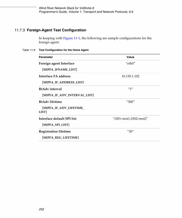
Wind River Network Stack for VxWorks 6Programmer's Guide, Volume 1: Transport and Network Protocols, 6.6
252
11.7.3 Foreign-Agent Test Configuration
In keeping with Figure 11-1, the following are sample configurations for the foreign agent:
Table 11-9 Test Configuration for the Home Agent
Parameter Value
Foreign agent Interface
[MIPFA_IFNAME_LIST]
“eth0”
Interface FA address
[MIPFA_IF_ADDRESS_LIST]
10.130.1.102
RtAdv interval
[MIPFA_IF_ADV_INTERVAL_LIST]
“3”
RtAdv lifetime
[MIPFA_IF_ADV_LIFETIME_LIST]
“300”
Interface default SPI list
[MIPFA_SPI_LIST]
"1001=test1;1002=test2”
Registration lifetime
[MIPFA_REG_LIFETIME]
“30”
253
12Wind River Mobile IPv6:
Mobile Node
12.1 Introduction 253
12.2 Conformance to Standards 253
12.3 Build Component and Build Parameters 254
12.4 Including the Mobile Node in a Build 261
12.5 Shell Commands 262
12.1 Introduction
This chapter describes the Wind River implementation of a mobile node for IPv6. For a general overview of Mobile IP see 8. Wind River Mobile IP: Overview.
12.2 Conformance to Standards
The Wind River mobile node for IPv6 implements, with a few exceptions, relevant features of the following RFCs:
■ RFC 3775, Mobility Support in IPv6
Wind River Network Stack for VxWorks 6Programmer's Guide, Volume 1: Transport and Network Protocols, 6.6
254
The following features of RFC 3775 are not implemented in the current release:
– Routing multicast packets (see section 11.3.4 of the RFC)– Return routability (see section 11.6 of the RFC)
■ RFC 3776, Using IPsec to Protect Mobile IPv6 Signaling Between Mobile Nodes and Home Agents
Dynamic keying, as described in RFC 3776, sections 4.4 and 5.3, is not implemented in the current release.
12.3 Build Component and Build Parameters
When you build VxWorks and the network stack, there is a required build component for Mobile IPv6 and a required build component for the mobile node. In addition, there is a separate build component for including access to shell commands for the mobile node. For information on the shell commands, see 12.5 Shell Commands, p.262. The build components are listed in the following table:
The IPv6 Mobile Node (INCLUDE_IPMIP6MN) build component provides a number of configuration parameters, as listed in Table 12-1. For each configuration parameter, the table gives the corresponding Workbench description, macro name, and sysvar.
Workbench Name Macro NameIPv6 Mobility Toolkit INCLUDE_IPMIP6IPv6 Mobile Node INCLUDE_IPMIP6MNIPv6 Mobile Node IPCOM commands INCLUDE_IPMIP6MN_CMD
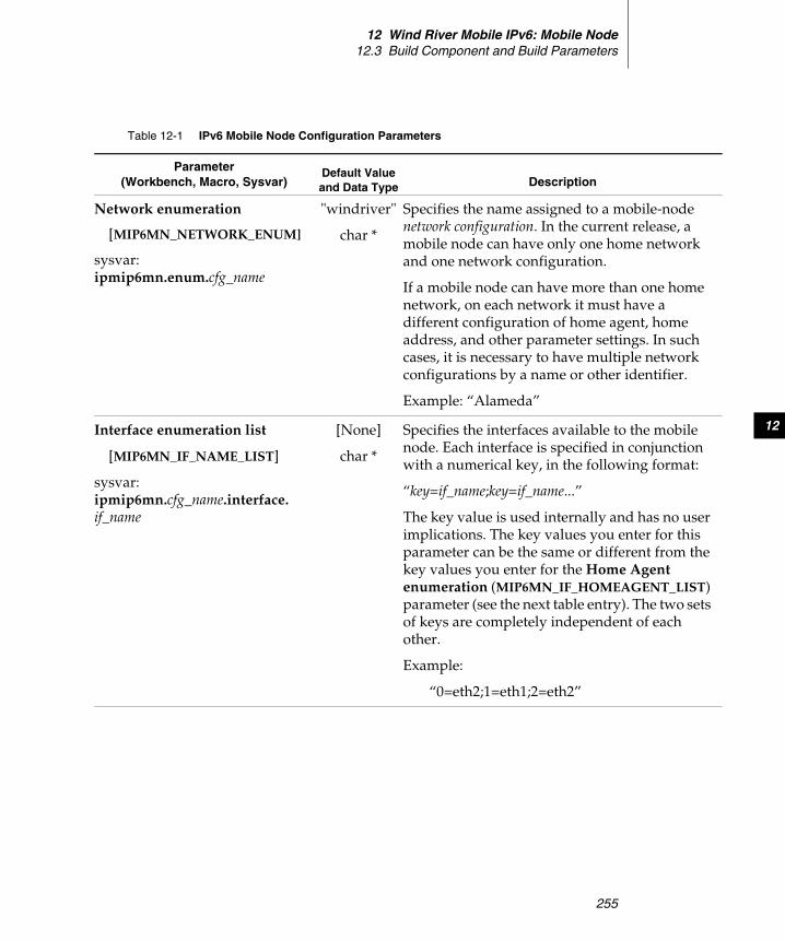
12 Wind River Mobile IPv6: Mobile Node12.3 Build Component and Build Parameters
255
12
Table 12-1 IPv6 Mobile Node Configuration Parameters
Parameter(Workbench, Macro, Sysvar)
Default Value and Data Type Description
Network enumeration
[MIP6MN_NETWORK_ENUM]
sysvar:ipmip6mn.enum.cfg_name
"windriver"
char *
Specifies the name assigned to a mobile-node network configuration. In the current release, a mobile node can have only one home network and one network configuration.
If a mobile node can have more than one home network, on each network it must have a different configuration of home agent, home address, and other parameter settings. In such cases, it is necessary to have multiple network configurations by a name or other identifier.
Example: “Alameda”
Interface enumeration list
[MIP6MN_IF_NAME_LIST]
sysvar:ipmip6mn.cfg_name.interface.if_name
[None]
char *
Specifies the interfaces available to the mobile node. Each interface is specified in conjunction with a numerical key, in the following format:
“key=if_name;key=if_name...”
The key value is used internally and has no user implications. The key values you enter for this parameter can be the same or different from the key values you enter for the Home Agent enumeration (MIP6MN_IF_HOMEAGENT_LIST) parameter (see the next table entry). The two sets of keys are completely independent of each other.
Example:
“0=eth2;1=eth1;2=eth2”
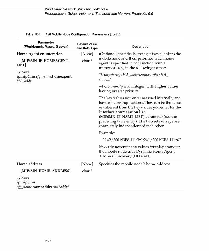
Wind River Network Stack for VxWorks 6Programmer's Guide, Volume 1: Transport and Network Protocols, 6.6
256
Home Agent enumeration
[MIP6MN_IF_HOMEAGENT_LIST]
sysvar:ipmip6mn.cfg_name.homeagent.HA_addr
[None]
char *
(Optional) Specifies home agents available to the mobile node and their priorities. Each home agent is specified in conjunction with a numerical key, in the following format:
“key=priority/HA_addr;key=priority/HA_addr;...”
where priority is an integer, with higher values having greater priority.
The key values you enter are used internally and have no user implications. They can be the same or different from the key values you enter for the Interface enumeration list (MIP6MN_IF_NAME_LIST) parameter (see the preceding table entry). The two sets of keys are completely independent of each other.
Example:
“1=2/2001:DB8:111:3::1;2=1/2001:DB8:111::6”
If you do not enter any values for this parameter, the mobile node uses Dynamic Home Agent Address Discovery (DHAAD).
Home address
[MIP6MN_HOME_ADDRESS]
sysvar:ipmip6mn.cfg_name.homeaddress=”addr”
[None]
char *
Specifies the mobile node’s home address.
Table 12-1 IPv6 Mobile Node Configuration Parameters (cont’d)
Parameter(Workbench, Macro, Sysvar)
Default Value and Data Type Description
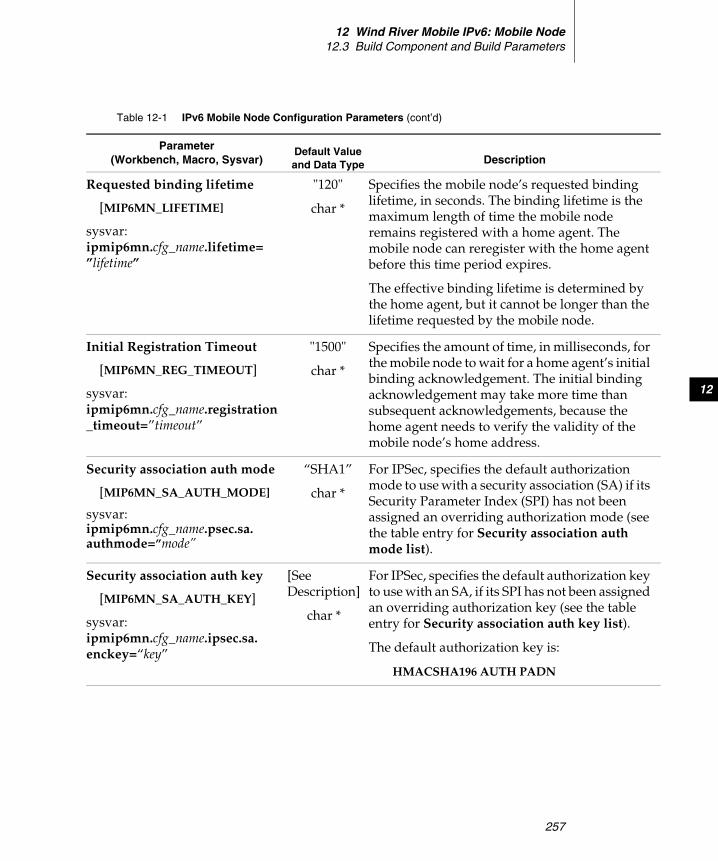
12 Wind River Mobile IPv6: Mobile Node12.3 Build Component and Build Parameters
257
12
Requested binding lifetime
[MIP6MN_LIFETIME]
sysvar:ipmip6mn.cfg_name.lifetime=”lifetime”
"120"
char *
Specifies the mobile node’s requested binding lifetime, in seconds. The binding lifetime is the maximum length of time the mobile node remains registered with a home agent. The mobile node can reregister with the home agent before this time period expires.
The effective binding lifetime is determined by the home agent, but it cannot be longer than the lifetime requested by the mobile node.
Initial Registration Timeout
[MIP6MN_REG_TIMEOUT]
sysvar:ipmip6mn.cfg_name.registration_timeout=”timeout”
"1500"
char *
Specifies the amount of time, in milliseconds, for the mobile node to wait for a home agent’s initial binding acknowledgement. The initial binding acknowledgement may take more time than subsequent acknowledgements, because the home agent needs to verify the validity of the mobile node’s home address.
Security association auth mode
[MIP6MN_SA_AUTH_MODE]
sysvar:ipmip6mn.cfg_name.psec.sa.authmode=”mode”
“SHA1”
char *
For IPSec, specifies the default authorization mode to use with a security association (SA) if its Security Parameter Index (SPI) has not been assigned an overriding authorization mode (see the table entry for Security association auth mode list).
Security association auth key
[MIP6MN_SA_AUTH_KEY]
sysvar:ipmip6mn.cfg_name.ipsec.sa.enckey=“key”
[SeeDescription]
char *
For IPSec, specifies the default authorization key to use with an SA, if its SPI has not been assigned an overriding authorization key (see the table entry for Security association auth key list).
The default authorization key is:
HMACSHA196 AUTH PADN
Table 12-1 IPv6 Mobile Node Configuration Parameters (cont’d)
Parameter(Workbench, Macro, Sysvar)
Default Value and Data Type Description
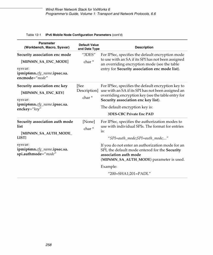
Wind River Network Stack for VxWorks 6Programmer's Guide, Volume 1: Transport and Network Protocols, 6.6
258
Security association enc mode
[MIP6MN_SA_ENC_MODE]
sysvar:ipmip6mn.cfg_name.ipsec.sa.encmode=“mode”
“3DES”
char *
For IPSec, specifies the default encryption mode to use with an SA if its SPI has not been assigned an overriding encryption mode (see the table entry for Security association enc mode list).
Security association enc key
[MIP6MN_SA_ENC_KEY]
sysvar:ipmip6mn.cfg_name.ipsec.sa.enckey=“key”
[SeeDescription]
char *
For IPSec, specifies the default encryption key to use with an SA if its SPI has not been assigned an overriding encryption key (see the table entry for Security association enc key list).
The default encryption key is:
3DES-CBC Private Enc PAD
Security association auth mode list
[MIP6MN_SA_AUTH_MODE_LIST]
sysvar:ipmip6mn.cfg_name.ipsec.sa.spi.authmode=“mode”
[None]
char *
For IPSec, specifies the authorization modes to use with individual SPIs. The format for entries is:
“SPI=auth_mode;SPI=auth_mode;...”
If you do not enter an authorization mode for an SPI, the default mode entered for the Security association auth mode (MIP6MN_SA_AUTH_MODE) parameter is used.
Example:
“200=SHA1;201=PADL”
Table 12-1 IPv6 Mobile Node Configuration Parameters (cont’d)
Parameter(Workbench, Macro, Sysvar)
Default Value and Data Type Description
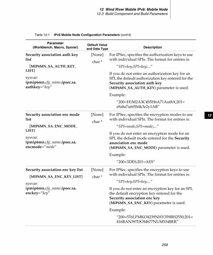
12 Wind River Mobile IPv6: Mobile Node12.3 Build Component and Build Parameters
259
12
Security association auth key list
[MIP6MN_SA_AUTH_KEY_LIST]
sysvar:ipmip6mn.cfg_name.ipsec.sa.authkey=“key”
[None]
char *
For IPSec, specifies the authorization keys to use with individual SPIs. The format for entries is:
“SPI=key;SPI=key;...”
If you do not enter an authorization key for an SPI, the default authorization key entered for the Security association auth key (MIP6MN_SA_AUTH_KEY) parameter is used.
Example:
“200=H1M2A3C4S5H6A71AuthX;201=s9a8a7u6t5h4k3e2y1AB”
Security association enc mode list
[MIP6MN_SA_ENC_MODE_LIST]
sysvar:ipmip6mn.cfg_name.ipsec.sa.encmode=“mode”
[None]
char *
For IPSec, specifies the encryption modes to use with individual SPIs. The format for entries is:
“SPI=mode;SPI=mode;...”
If you do not enter an encryption mode for an SPI, the default mode entered for the Security association enc mode (MIP6MN_SA_ENC_MODE) parameter is used.
Example:
“200=3DES;201=AES“
Security association enc key list
[MIP6MN_SA_ENC_KEY_LIST]
sysvar:ipmip6mn.cfg_name.ipsec.sa.enckey=“key”
[None]
char *
For IPSec, specifies the encryption keys to use with individual SPIs. The format for entries is:
“SPI=key;SPI=key;...”
If you do not enter an encryption key for an SPI, the default encryption key entered for the Security association enc key (MIP6MN_SA_ENC_KEY) parameter is used.
Example:
“200=576LPMKO4239NHY359BH2550;201=416RAN397DOM677NUM534BER”
Table 12-1 IPv6 Mobile Node Configuration Parameters (cont’d)
Parameter(Workbench, Macro, Sysvar)
Default Value and Data Type Description
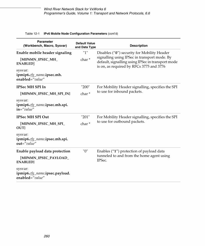
Wind River Network Stack for VxWorks 6Programmer's Guide, Volume 1: Transport and Network Protocols, 6.6
260
Enable mobile header signaling
[MIP6MN_IPSEC_MH_ENABLED]
sysvar:ipmip6.cfg_name.ipsec.mh.enabled=”value”
"1"
char *
Disables (“0”) security for Mobility Header signalling using IPSec in transport mode. By default, signalling using IPSec in transport mode is on, as required by RFCs 3775 and 3776
IPSec MH SPI In
[MIP6MN_IPSEC_MH_SPI_IN]
sysvar:ipmip6.cfg_name.ipsec.mh.spi.in=”value”
"200"
char *
For Mobility Header signalling, specifies the SPI to use for inbound packets.
IPSec MH SPI Out
[MIP6MN_IPSEC_MH_SPI_OUT]
sysvar:ipmip6.cfg_name.ipsec.mh.spi.out=”value”
"201"
char *
For Mobility Header signalling, specifies the SPI to use for outbound packets.
Enable payload data protection
[MIP6MN_IPSEC_PAYLOAD_ENABLED]
sysvar:ipmip6.cfg_name.ipsec.payload.enabled=”value”
"0" Enables (“1”) protection of payload data tunneled to and from the home agent using IPSec.
Table 12-1 IPv6 Mobile Node Configuration Parameters (cont’d)
Parameter(Workbench, Macro, Sysvar)
Default Value and Data Type Description
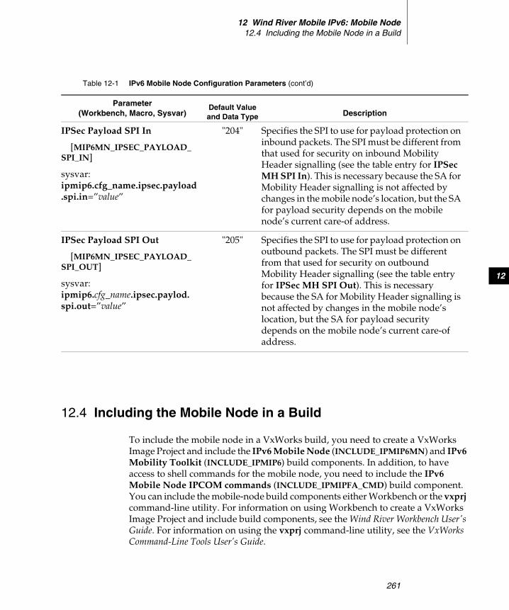
12 Wind River Mobile IPv6: Mobile Node12.4 Including the Mobile Node in a Build
261
12
12.4 Including the Mobile Node in a Build
To include the mobile node in a VxWorks build, you need to create a VxWorks Image Project and include the IPv6 Mobile Node (INCLUDE_IPMIP6MN) and IPv6 Mobility Toolkit (INCLUDE_IPMIP6) build components. In addition, to have access to shell commands for the mobile node, you need to include the IPv6 Mobile Node IPCOM commands (INCLUDE_IPMIPFA_CMD) build component. You can include the mobile-node build components either Workbench or the vxprj command-line utility. For information on using Workbench to create a VxWorks Image Project and include build components, see the Wind River Workbench User's Guide. For information on using the vxprj command-line utility, see the VxWorks Command-Line Tools User’s Guide.
IPSec Payload SPI In
[MIP6MN_IPSEC_PAYLOAD_SPI_IN]
sysvar:ipmip6.cfg_name.ipsec.payload.spi.in=”value”
"204" Specifies the SPI to use for payload protection on inbound packets. The SPI must be different from that used for security on inbound Mobility Header signalling (see the table entry for IPSec MH SPI In). This is necessary because the SA for Mobility Header signalling is not affected by changes in the mobile node’s location, but the SA for payload security depends on the mobile node’s current care-of address.
IPSec Payload SPI Out
[MIP6MN_IPSEC_PAYLOAD_SPI_OUT]
sysvar:ipmip6.cfg_name.ipsec.paylod.spi.out=”value”
"205" Specifies the SPI to use for payload protection on outbound packets. The SPI must be different from that used for security on outbound Mobility Header signalling (see the table entry for IPSec MH SPI Out). This is necessary because the SA for Mobility Header signalling is not affected by changes in the mobile node’s location, but the SA for payload security depends on the mobile node’s current care-of address.
Table 12-1 IPv6 Mobile Node Configuration Parameters (cont’d)
Parameter(Workbench, Macro, Sysvar)
Default Value and Data Type Description
Wind River Network Stack for VxWorks 6Programmer's Guide, Volume 1: Transport and Network Protocols, 6.6
262
Once you include the IPv6 Mobile Node (INCLUDE_IPMIP6MN) and IPv6 Mobility Toolkit (INCLUDE_IPMIP6) build components in your build, you can set values for the static configuration parameters listed in Table 12-1.
12.5 Shell Commands
The shell commands for the mobile node are designed so that they can be used with multiple network configurations, although the current release supports only a single network configuration. The shell commands allow you to:
■ List the home agent and home address for each network configuration.
■ Display statistics on mobile-node activities
■ Display status information about network configurations.
Table 12-2 lists the mobile-node shell commands.
Table 12-2 Mobile IPv6 Mobile Node Shell Commands
Command Description
mn6 list Lists the home agent and home address for each network configuration. In the current release, only one network configuration is supported. For sample output, see 12.5.1 Sample Output for the mn6 list Shell Command, p.264.
mn6 statistics [-v] [-a] [-i index] [-n network_name] [-h home_addr]
Displays statistics on the mobile node’s activities, according to the options entered. Currently, only a single network configuration is supported. The options available for mn6 show. For a description of the available options see the table entry for mn6 status. Note that the mn6 statistics shell command does not have a -s option, although the mn6 status command does.
For sample output, see 12.5.2 Sample Output for the mn6 statistics Shell Command, p.264.

12 Wind River Mobile IPv6: Mobile Node12.5 Shell Commands
263
12
mn6 status [-v] [-s] [-a] [-i index] [-n network_name] [-h home_addr]
Displays status information about network configurations, according to the options entered. Currently, only a single network configuration is supported. The options available for mn6 show are:
-v Verbose output.
-sShort mode; only basic status information is provided
-aGives extended information about all network configurations.
-i index(Not implemented in the current release) Gives information only about the network configuration with the specified index value.
-n network_nameGives information only about the specified network.
-h home_addrGives information only about the network configuration with the specified home address.
For sample output, see 12.5.3 Sample Output for the mn6 status Shell Command, p.265.
Table 12-2 Mobile IPv6 Mobile Node Shell Commands (cont’d)
Command Description
Wind River Network Stack for VxWorks 6Programmer's Guide, Volume 1: Transport and Network Protocols, 6.6
264
12.5.1 Sample Output for the mn6 list Shell Command
The mn6 list shell command lists the home agent and home address for each network configuration. Currently, only one configuration is supported. The following is sample output:
>mn6 listIndex: 1Network: wrInterface: gifwr0Address: 2000:70::103:0:0:0:12
12.5.2 Sample Output for the mn6 statistics Shell Command
Displays statistics on the mobile node’s activities, according to the options entered. Currently, only a single network configuration is supported. The following is sample output:
>mn6 statistics -aIndex: 1Network: wrInterface: gifwr0Address: 2001:DB8::103:0:0:0:12
Discovery and Advertisement:Discovery Requests: 1Discovery Replies: 1Discovery Timeouts: 0Moved To FN: 1Moved To HN: 0Prefix Advs Recvd: 0Prefix Advs Ignored: 0Prefix Sol Sent: 0
Registration Counters:Binding Errors from CN: 0Binding Refresh Req Recvd: 0Binding Acks from CN: 0Binding Acks from HA: 1Binding Updates to CN: 0Binding Updates to HA: 1ICMP Errors Recvd: 0Mobility Messages Recvd: 1Mobility Messages Sent: 1
Traffic Counters:Counter Discontinuity Time: May 02 13:06:54Received Bytes: 467904Received Frames: 680Sent Bytes: 545652Sent Frames: 712
12 Wind River Mobile IPv6: Mobile Node12.5 Shell Commands
265
12
12.5.3 Sample Output for the mn6 status Shell Command
The mn6 status shell command gives status information about network configurations, according to the options entered. Currently, only a single network configuration is supported. The following is sample output:
> mn6 status -n wrIndex: 28Network: wrInterface: gifwr0Address: 2001:DB8::103:0:0:0:12
Status: RegisteredHome Address: 2001:DB8::103:0:0:0:12Peer Address: 2001:DB8::103:0:0:0:10COA: 2001:DB8::105:200:FF:FE00:2Accepted: TrueLifetime Requested: 120Lifetime Granted: 120Time Sent: Mar 26 13:49:05Accepted Time: Mar 26 13:49:06Max Sequence: 55470Retransmissions: 0

Wind River Network Stack for VxWorks 6Programmer's Guide, Volume 1: Transport and Network Protocols, 6.6
266
267
AGlossary
A.1 Introduction 267
A.2 Terms 267
A.3 Abbreviations and Acronyms 275
A.1 Introduction
This chapter contains brief definitions of networking terms, acronyms, and abbreviations used in discussions in this manual.
A.2 Terms
This section defines terms used in the Wind River Network Stack documentation. It includes both standard industry terms and clarifies terms used in this book whose meaning, in the context of this product, differs from another definition used in the industry.
Wind River Network Stack for VxWorks 6Programmer's Guide, Volume 1: Transport and Network Protocols, 6.6
268
ALG
The Application Level Gateway is a module used together with NAT to support protocols that embed address information in the payload data. An ALG is sometimes also called application proxy.
API
An Application Programmming Interface (API) is the syntax and semantics of the interface.
callback
In this document, a callback is a routine that is called from within the kernel code. An example is the socket specific asynchronous input function.
control plane
The control plane refers to the code that calls into the stack to configure the multicast forwarding table.
daemon
A daemon is a term that originates from UNIX and refers to a task that is running in the background. The Wind River multicasting daemon is the task that implements the multicast routing duties as required by a multicast proxy specification.
datagram
A datagram is a self-contained packet used in packet switching. A datagram contains enough information in the header to allow the network to forward it to the destination independently of previous or future datagrams. Thus, no setup is needed before a computer tries to send datagrams to a computer with which it has not previously communicated, unlike with virtual circuit protocols. See also packet, p.272.
data link layer
The data link layer is layer two of the seven-layer Open Systems Interconnection (OSI) model. It transfers data between adjacent network nodes in a wide area network or between nodes on the same local area network segment. The data link layer prepares the packets for transmission, and detects and handles errors, such as packet collision. Examples of data link protocols are Ethernet for local area networks and PPP (Point-to-Point Protocol) for point-to-point connections.
A GlossaryA.2 Terms
269
A
data plane
The data plane is the code that makes up the forwarding step, for example, in the context of multicasting.
descriptor
A descriptor is an integer assigned by the system when a socket is created by ipnet_socket( ) which uniquely identifies an access path to that file or socket from a given process or any of its children.
egress filtering
Egress filtering is a method of securing a network by monitoring and filtering packets that leave an internal network to external networks (internet) via a router. Egress filtering makes a system less prone to attack from hackers by ensuring that spoofed packets never leave an internal network. See also, ingress filtering, p.270.
END driver
An END driver is a frame-oriented drivers that exchange frames with the MUX. See also, NPT driver, p.272 and MUX, p.271.
fast path
A fast path is a fast IP-forwarding mechanism that intercepts packets before they are passed up to IP. If the packet is destined for a location known to the fast path route cache (also known as the FIB, the Forwarding Information Base), the application forwards the packet. If the destination is unknown to the FIB, the application leaves the packet to IP.
firewall
A firewall is a piece of hardware or software used in a networked environment to prevent communications that are forbidden by the security policy. A common type of firewall is a router retrofitted with extra software for packet filtering based on a list of rules or criteria.
flow
A flow is a sequence of packets sent from a particular source to a particular (unicast or multicast) destination for which the source desires special handling by the intervening routers.
Wind River Network Stack for VxWorks 6Programmer's Guide, Volume 1: Transport and Network Protocols, 6.6
270
gif interface
A gif interface is a generic tunneling pseudo device for IPv4 and IPv6. It can tunnel IPv[46] traffic over IPv[46]. Therefore, there can be four possible configurations. The behavior of gif is mainly based on RFC2893 IPv6-over-IPv4 configured tunnel. See also, stf interface, p.274.
group
A group (in the context of multicasting) is a specific IP address for which there can be zero or more listeners. A IP datagram sent to a group should be delivered to all nodes listening to that group.
host
A host is any node that does not act as a router.
IETF
The Internet Engineering Task Force is an international community of network designers, operators, vendors, and researchers who work in groups on Internet standards. IEFTF is described fully a their website: http://www.ietf.org
ingress filtering
Ingress filtering is the application of a firewall rulebase to inbound traffic. Ingress filtering allows you to control the traffic that enters your network and restrict activity to legitimate purposes. See also egress filtering, p.269 and firewall, p.269.
IP address
An IP address refers to the address of a node.
IPv6
IPv6 stands for Internet Protocol version 6, the latest level of the Internet Protocol. The most obvious improvement in IPv6 over the IPv4 is that IP addresses are lengthened from 32 bits to 128 bits. This extension anticipates future growth of the Internet and provides relief for what was perceived as an impending shortage of network addresses.
jumbogram
A jumbogram is a transmission packet that contains a payload larger than 65,535 eight-bit bytes (also known as octets). IPv6 is able to carry a jumbogram.
A GlossaryA.2 Terms
271
A
MAC
MAC (Medium Access Control) is the part of the data link layer that governs access to the transmission media and is the method of determining which device has access to the Ethernet collision domain at any given time. See data link layer, p.268.
MAC Interface
The MAC interface is the Ethernet interface used by the SNMP agent in the network device for communications to and from another device.
MLD
Multicast Listener Discovery (MLD) is one of the protocols needed to support multicasting in the IPv6 domain.
MPLS
Multi-Protocol Label Switching (MPLS) is an IETF standards-approved technology for speeding up network traffic flow and making it easier to manage. The strength of MPLS is that the route analysis of an IP packet need only be done once, at the ingress side of the MPLS path, by an edge router.
MRU
The Maximum-Receive-Unit (MRU) is the largest physical packet size measured in bytes, that a network can receive.
MTU
The Maximum Transmission Unit (MTU) is the largest physical packet size measured in bytes that can be transmitted to the network.
multicast proxy
A multicast proxy is a way of implementing a multicast router node. The proxy has some restrictions on the network topology in which it is operating. These restrictions are described in the RFC on which the implementation is based.
MUX
The MUX is an interface layer through which the network services communicate with the data link layer. MUX decouples the network driver and network protocol layers, thereby allowing you to add new network drivers without having to alter the network protocol, or to add a new network protocol without having to alter the MUX_based network interface drivers. Currently, the MUX supports two network
Wind River Network Stack for VxWorks 6Programmer's Guide, Volume 1: Transport and Network Protocols, 6.6
272
driver interface styles, the END interface and the Network Protocol Toolkit (NPT) driver interface. See also, END driver, p.269 and NPT driver, p.272.
node
A node is a device that has a network connection.
NPT driver
An NPT driver is an implementation of the OSI Data link layer that makes use of MUX functions. The NPT (Network Protocol Toolkit) style drivers are packet-oriented drivers that exchange packets with the MUX. See also, END driver, p.269 and MUX, p.271.
OSI network model
The OSI network model is a description of seven layers through which data passes when transmitted from an application on one machine to a peer on a remote network-connected machine. In practice, only four layers are usually implemented: the application layer, the transport layer, the network layer, and the data link layer.
packet
A packet is a collection of bits, comprising data and control information—including a header, which contains the packet’s source and destination IP addresses—formatted for transmission, by protocols, from one node to another.
packet filtering
Packet filtering is the selective passing or blocking of data packets as they pass through a network interface, specifically between the network and transport layers. The most commonly-used criteria when inspecting packets are source and destination address, source and destination port, and protocol. Filter rules specify the criteria that a packet must match and the resulting action taken.
PPP
The Point-to-Point Protocol (PPP), defined in RFC1661, it provides a standard method for transporting multi-protocol datagrams over point-to-point links.
process ID
Each active process in the system is uniquely identified by a nonnegative integer called a process ID.
A GlossaryA.2 Terms
273
A
protocol
A network protocol is a standardized format for communication or data transmission between two devices. For example, network protocol rules can specify the packet format, data compression, timing, sequencing, and error checking for data transmission. A given protocol usually applies to software and hardware elements operating at the same OSI layer. However, a protocol can be used to mean a set or suite of protocols that can span layers, as in the case of TCP/IP. See also, OSI network model, p.272 and TCP/IP, p.274.
RFCs
RFCs (Request for Comments) are publicly available documents that contain research, innovations, and methodologies applicable to Internet technologies. The Internet Engineering Task Force (IETF, p.270) adopts some of the applied information theory published in RFCs as official Internet standards. Not all RFCs represent IETF standards—some are just informational.
router
A router is a device that determines which paths to use through a network to transmit data. Routers operate at the network layer in the OSI model, providing intelligent connections between networks.
In multicasting, a router is a node that can move IP datagrams from one interface to another in order to move the packet closer to the destination node. The term multicast proxy is equivalent to multicast router, with the restrictions described by the RFC that is used to implement the multicast proxy.
SNARF protocol
A SNARF protocol is a protocol that sees all packets first and that acts as a filter for other protocols, by determining whether or not a packet is passed on.
socket
An internet socket is one end-point of a two-way communication link used by processes to communicate over a network. An internet socket is identified by a unique number defined by the TCP/IP protocol (for example, a combination of an IP address, a protocol, and a port number). Sockets provide information to the transport layer protocol. Each socket has queues for sending and receiving data Data written by a program to the socket at one end of the connection is transmitted to the socket on the other end of the connection, where it can be read by the program at that end.
Wind River Network Stack for VxWorks 6Programmer's Guide, Volume 1: Transport and Network Protocols, 6.6
274
stf interface
An stf interface is a 6to4 tunnel interface that can tunnel IPv6 traffic over IPv4, as specified in RFC3056. For ordinary nodes in 6to4 site, you do not need stf interface. The stf interface is necessary for site border router (called "6to4 router" in the specification). See also, gif interface, p.270.
target
A target refers to the hardware, that is, the CPU and board combination that the RTOS (see A.3 Abbreviations and Acronyms, p.275) is running on.
TCP/IP
TCP/IP is a suite of communication protocols that includes TCP and IP. It is used to connect hosts on the Internet and is built into the UNIX operating system. See also, protocol, p.273.
transport layer
The transport layer is the functionality in the OSI network model that provides transparent, reliable, and cost-effective transfer of data between end users. The transport layer controls the reliability of a given link, keeping track of the packets and retransmitting those that fail. TCP, UDP, RTP, and SCTP (listed in Abbreviations and Acronyms, p.275) are examples of transport layer protocols. See also, OSI network model, p.272.
tunneling
A tunneling protocol is a network protocol that encapsulates one protocol or session inside another. Tunneling can be used to transport a network protocol through a network that would not otherwise support it. Corporations make use of tunneling to extend the corporate network through private “tunnels” over the public Internet. This kind of interconnection is known as a virtual private network (VPN) and can provide functionality such as private addressing.
UDP
UDP, which stands for User Datagram Protocol, is a relatively fast and connectionless protocol that runs at the transport layer on top of IP networks. Because it has very few error recovery services (unlike TCP), it is used primarily for broadcasting messages and for other applications that do not require a connection. See also, datagram, p.268, protocol, p.273, and transport layer, p.274.
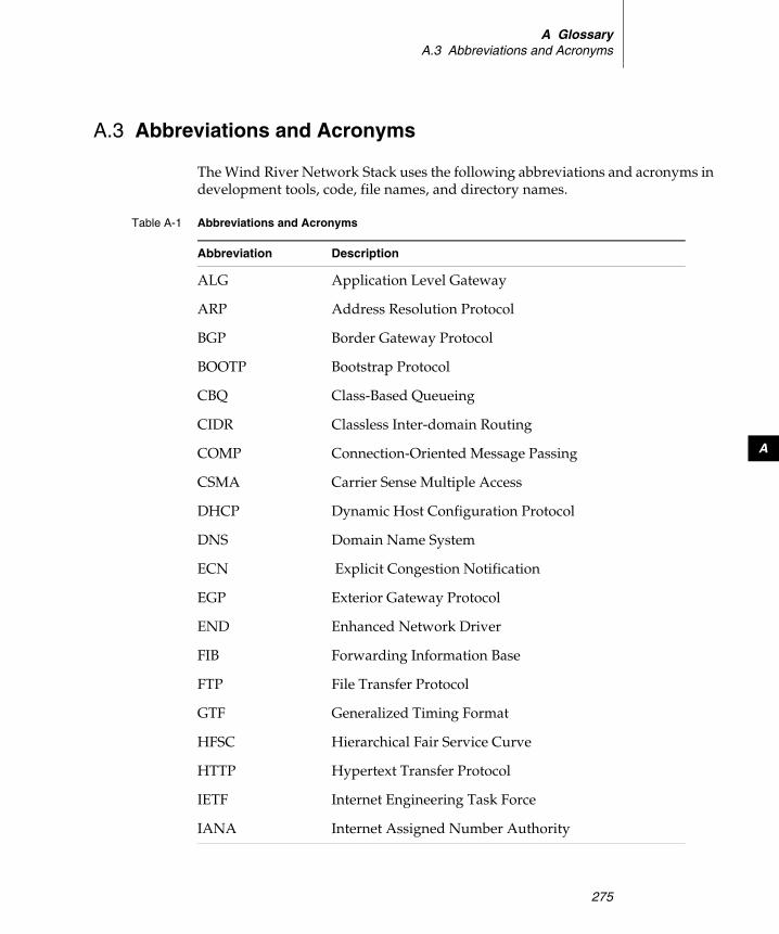
A GlossaryA.3 Abbreviations and Acronyms
275
A
A.3 Abbreviations and Acronyms
The Wind River Network Stack uses the following abbreviations and acronyms in development tools, code, file names, and directory names.
Table A-1 Abbreviations and Acronyms
Abbreviation Description
ALG Application Level Gateway
ARP Address Resolution Protocol
BGP Border Gateway Protocol
BOOTP Bootstrap Protocol
CBQ Class-Based Queueing
CIDR Classless Inter-domain Routing
COMP Connection-Oriented Message Passing
CSMA Carrier Sense Multiple Access
DHCP Dynamic Host Configuration Protocol
DNS Domain Name System
ECN Explicit Congestion Notification
EGP Exterior Gateway Protocol
END Enhanced Network Driver
FIB Forwarding Information Base
FTP File Transfer Protocol
GTF Generalized Timing Format
HFSC Hierarchical Fair Service Curve
HTTP Hypertext Transfer Protocol
IETF Internet Engineering Task Force
IANA Internet Assigned Number Authority
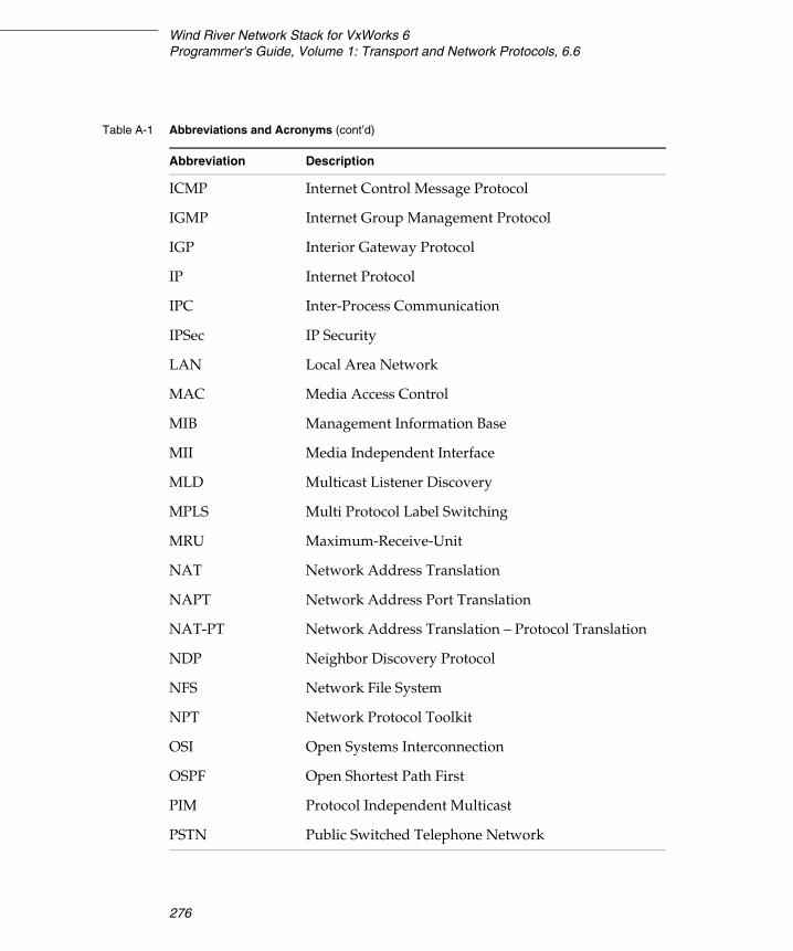
Wind River Network Stack for VxWorks 6Programmer's Guide, Volume 1: Transport and Network Protocols, 6.6
276
ICMP Internet Control Message Protocol
IGMP Internet Group Management Protocol
IGP Interior Gateway Protocol
IP Internet Protocol
IPC Inter-Process Communication
IPSec IP Security
LAN Local Area Network
MAC Media Access Control
MIB Management Information Base
MII Media Independent Interface
MLD Multicast Listener Discovery
MPLS Multi Protocol Label Switching
MRU Maximum-Receive-Unit
NAT Network Address Translation
NAPT Network Address Port Translation
NAT-PT Network Address Translation – Protocol Translation
NDP Neighbor Discovery Protocol
NFS Network File System
NPT Network Protocol Toolkit
OSI Open Systems Interconnection
OSPF Open Shortest Path First
PIM Protocol Independent Multicast
PSTN Public Switched Telephone Network
Table A-1 Abbreviations and Acronyms (cont’d)
Abbreviation Description
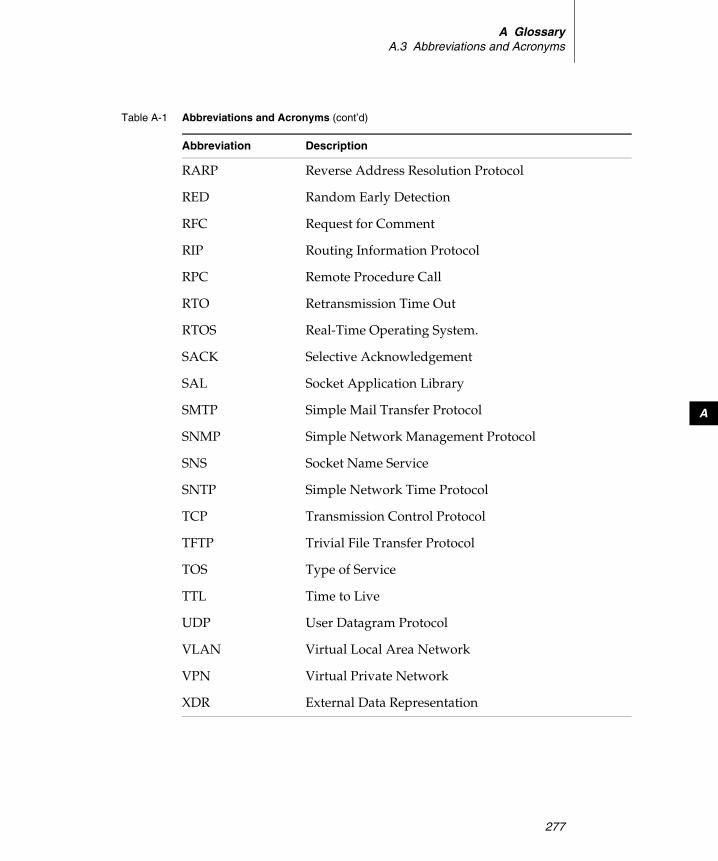
A GlossaryA.3 Abbreviations and Acronyms
277
A
RARP Reverse Address Resolution Protocol
RED Random Early Detection
RFC Request for Comment
RIP Routing Information Protocol
RPC Remote Procedure Call
RTO Retransmission Time Out
RTOS Real-Time Operating System.
SACK Selective Acknowledgement
SAL Socket Application Library
SMTP Simple Mail Transfer Protocol
SNMP Simple Network Management Protocol
SNS Socket Name Service
SNTP Simple Network Time Protocol
TCP Transmission Control Protocol
TFTP Trivial File Transfer Protocol
TOS Type of Service
TTL Time to Live
UDP User Datagram Protocol
VLAN Virtual Local Area Network
VPN Virtual Private Network
XDR External Data Representation
Table A-1 Abbreviations and Acronyms (cont’d)
Abbreviation Description

Wind River Network Stack for VxWorks 6Programmer's Guide, Volume 1: Transport and Network Protocols, 6.6
278
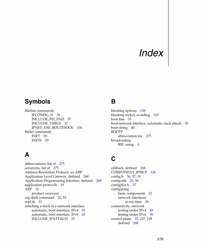
279
Index
Symbols#define commands
IFCONFIG_N 39INCLUDE_FEI_END 37INCLUDE_VXBUS 37IPNET_USE_ROUTESOCK 104
#ifdef commandsINET 29INET6 29
Aabbreviations, list of 275acronyms, list of 275Address Resolution Protocol, see ARPApplication Level Gateway, defined 268Application Programming Interface, defined 268application protocols 19ARP 52
product overviewarp shell command 52, 53arpLib 53attaching a stack to a network interface
automatic, boot interface, IPv4 59automatic, boot interface, IPv6 65INCLUDE_IPATTACH 35
Bblocking options 138blocking socket, avoiding 103boot line 35boot network interface, automatic stack attach 59boot string 40BOOTP
abbreviation for 275broadcasting
RIP, using 3
Ccallback, defined 268COMPONENT_IPMCP 126config.h 36, 37, 39config.mk 29, 96configNet.h 37configuring
basic components 32network interfaces
at run time 39connectivity, network
testing under IPv4 49testing under IPv6 50
control plane 15, 127, 128defined 268

Wind River Network Stack for VxWorks 6 Programmer's Guide, Volume 1: Transport and Network Protocols, 6.6
280
Ddata link layer, defined 268data plane 15, 128data plane, defined 269datagram, defined 268debugging 31descriptor, defined 269devname parameter 38domain value, routing socket 103downstream interfaces 139dual IPv4/IPv6 network stack
General Purpose Platform 30Wind River Platforms 29
Eegress filtering, defined 269END driver, defined 269Ethernet fast path 95Ethernet support 35
Ffast IP-forwarding, see fast pathfast path 95
defined 269Ethernet 95generic 95optional modifiers 99
FEATURE_IPNET_BUILD 31FEATURE_IPNET_INET6 29FEATURE_IPNET_INET6_ONLY 29FEATURE_IPNET_VERBOSE 31features in Platforms, see Wind River Platformsfeatures in Wind River Platforms 6FIB 90FIONBIO 103firewall 96
defined 269forwarding information base, see FIB
Ggateway parameter 38gateway6 parameter 39General Timer Facility
starting, build-time configuration 34generic fast path 95gif interface, defined 270glossary of terms 267group options 137
HHighest Random Weight algorithm 102host groups 135hostShow library 69hostShow( ) routine 69
IICMP 55
product overview 8ICMPv4 34ICMPv6
product overview 8IETF standards 21if.h 112ifconfig shell command 39IFCONFIG_N parameter 38ifname parameter 38IGMP 127IGMPv1 135IGMPv2 135IGMPv3 135IINCLUDE_IPCOM_USE_INET6,adding 60INCLUDE_APPL_LOG_UTIL 35INCLUDE_ARP_API 53INCLUDE_BOOT_LINE_INIT 35INCLUDE_COMMON_NET 33INCLUDE_FEI_END 37INCLUDE_GTF 34INCLUDE_GTF_TIMER_START 34
Index
281
Index
INCLUDE_INETLIB 34INCLUDE_IP6ATTACH 35INCLUDE_IP6ATTACH, adding 65INCLUDE_IPARP_CMD 52INCLUDE_IPATTACH 35
adding 59INCLUDE_IPCOM 33INCLUDE_IPCOM_SHELL_CMD 45INCLUDE_IPCOM_SYSLOGD_CMD 47INCLUDE_IPCOM_SYSVAR_CMD 48, 128INCLUDE_IPCOM_USE_ETHERNET
required for basic stack 35INCLUDE_IPCOM_USE_INET 34
adding 56INCLUDE_IPCOM_USE_INET4 59INCLUDE_IPCOM_USE_INET6 65INCLUDE_IPD_CMD 46INCLUDE_IPDNSC
modifying default values 41INCLUDE_IPMCAST_PROXY_CMD 128, 133INCLUDE_IPMCP 128, 129INCLUDE_IPMCP_USE_IGMP 127, 135INCLUDE_IPMCP_USE_MLD 128, 135INCLUDE_IPMIP6 (build component) 254INCLUDE_IPMIP6MN (build component) 254INCLUDE_IPMIP6MN_CMD (build
component) 254INCLUDE_IPMIPFA (build component) 223INCLUDE_IPMIPFA_AAA_DIAMETER (build
component) 223INCLUDE_IPMIPFA_AAA_RADIUS (build
component) 223INCLUDE_IPMIPFA_CMD (build
component) 223INCLUDE_IPMIPHA (build component) 191INCLUDE_IPMIPHA_AAA_DIAMETER (build
component) 192INCLUDE_IPMIPHA_AAA_RADIUS (build
component) 192INCLUDE_IPMIPHA_CMD (build
component) 191INCLUDE_IPMIPMN (build component) 163INCLUDE_IPMPLS 69, 70INCLUDE_IPMPLS_TUNNEL 69INCLUDE_IPNDP_CMD 66
INCLUDE_IPNET 33INCLUDE_IPNET_IFCONFIG_N component 38INCLUDE_IPNET_STACK 33INCLUDE_IPNET_USE_MCAST_ROUTING 127,
128INCLUDE_IPNET_USE_ROUTESOCK 103INCLUDE_IPNET6_USE_MCAST_ROUTING 128INCLUDE_IPPING_CMD 35INCLUDE_IPPING6_CMD 35INCLUDE_IPPROXYARP, adding 54INCLUDE_IPRIP_CTRL_CMD 12INCLUDE_IPRIP_STATIC_ROUTE_1 82INCLUDE_IPRIP_STATIC_ROUTE_2 82INCLUDE_IPRIPNG 83INCLUDE_IPRIPNG_CTRL_CMD 83INCLUDE_IPTCP 34, 67INCLUDE_IPVERSION_CMD 47INCLUDE_IPVRRPD 93INCLUDE_NET_BOOT 35INCLUDE_NET_BOOT_CONFIG 35INCLUDE_NET_DAEMON
configuring 41, 43INCLUDE_NET_DRV 40INCLUDE_NET_DRV 35INCLUDE_NET_HOST_SETUP 35INCLUDE_NET_HOST_SHOW, adding 69INCLUDE_NET_REM_IO 35INCLUDE_NET_SYSCTL 36INCLUDE_PING 36INCLUDE_PING6 36INCLUDE_RIP 88INCLUDE_RIPNG 86INCLUDE_RIPNG_CTRL_CMD 12INCLUDE_SOCKLIB 33INCLUDE_SYSCTL 36INCLUDE_USE_NATIVE_SHELL 45INCLUDE_XDR 36inet dhcp parameter 38inet driver parameter 38inet parameter 38inet rarp parameter 38INET_AUTO_PROXY_ARP 55INET_BASE_HOP_LIMIT 56INET_BASE_REACHABLE_TIME 56INET_BASE_RETRANSMIT_TIME 56
Wind River Network Stack for VxWorks 6 Programmer's Guide, Volume 1: Transport and Network Protocols, 6.6
282
INET_DELAY_FIRST_PROBE_TIME 56INET_DST_CACHE_TO_LIVE_TIME 56INET_ENABLE_PROXY_ARP 55INET_ICMP_IGNORE_ECHO_REQ 56INET_ICMP_IGNORE_TIMESTAMP_REQ 57INET_ICMP_RATE_LIMIT_BUCKET_SIZE 57INET_ICMP_RATE_LIMIT_INTERVAL 57INET_ICMP_REDIRECT_RECEIVE 57INET_ICMP_REDIRECT_SEND 58INET_ICMP_SEND_DST_UNREACHABLE 58INET_ICMP_SEND_TIME_EXCEEDED 58INET_IFLIST_AUTO_PROXY_ARP 55INET_IFLIST_ENABLE_PROXY_ARP 55INET_MAX_APP_SOLICIT 58INET_MAX_MULTICAST_SOLICIT 58INET_MAX_PKTS_PENDING 58INET_MAX_UNICAST_SOLICIT 59INET_MIN_MTU_SIZE 59INET_NBR_CACHE_TO_LIVE_TIME 59-inet6 command-line flag 33inet6 parameter 39INET6_ACCEPT_RTADV 60INET6_AUTO_CONFIG 60INET6_BASE_HOP_LIMIT 60INET6_BASE_REACHABLE_TIME 60INET6_BASE_RETRANSMIT_TIME 60INET6_DAD_TRANSMITS 61INET6_DELAY_FIRST_PROBE_TIME 61INET6_DST_CACHE_TO_LIVE_TIME 61, 63INET6_ICMP_IGNORE_ECHO_REQ 61, 63INET6_ICMP_RATE_LIMIT_BUCKET_SIZE 61,
63INET6_ICMP_RATE_LIMIT_INTERVAL 61, 63INET6_ICMP_REDIRECT_RECEIVE 61, 63INET6_ICMP_REDIRECT_SEND 62INET6_ICMP_SEND_DST_UNREACHABLE 62,
64INET6_ICMP_SEND_TIME_EXCEEDED 62, 64INET6_MAX_APP_SOLICIT 62, 64INET6_MAX_MULTICAST_SOLICIT 62, 64INET6_MAX_PKTS_PENDING 62, 64INET6_NBR_CACHE_TO_LIVE_TIME 65INET6_ROUTER_LIFETIME 65inetLib, component 34ingress filtering, defined 270
interface, network driver, including 36Internet Control Message Protocol, see ICMPInternet Engineering Task Force, defined 270Internet Group Management Protocol, see IGMPInternet Protocol, see IPIP
product overview 8specifying version 28
ip_mroute.h 149ip6Attach( ) 35, 65ipAttach shell command 39ipAttach( ) 35, 65ipd shell command 46, 132ipmcp.DownstreamIfs 129ipmcp.LastListenerQueryInterval 129ipmcp.QueryInterval 130ipmcp.QueryResponseInterval 130ipmcp.RobustnessVariable 131ipmcp.UpstreamIf 131IPMPLS_FWDCONF_SYSVAR 70ipnet.inet.AutoProxyArp 55ipnet.inet.BaseHopLimit 56ipnet.inet.BaseReachableTime 56ipnet.inet.BaseRetransmitTime 56ipnet.inet.EnableNetworkProxyArp 55ipnet.inet.EnablePathMtuDiscovery 60ipnet.inet.IcmpIgnoreEchoRequest 56ipnet.inet.IcmpIgnoreTimestampRequest 57ipnet.inet.IcmpRatelimitBucketsize 57ipnet.inet.IcmpRatelimitInterval 57ipnet.inet.IcmpRedirectReceive 57ipnet.inet.IcmpRedirectSend 58ipnet.inet.IcmpSendDestinationUnreachable 58ipnet.inet.IcmpSendTimeExceeded 58ipnet.inet.MaxApplicationSolicit 58ipnet.inet.MaxMulticastSolicit 58ipnet.inet.MaxUnicastSolicit 59ipnet.inet.NeighborCacheToLive 59ipnet.inet.UdpChecksum 60ipnet.inet6.AcceptRtAdv 60ipnet.inet6.BaseHopLimit 60ipnet.inet6.BaseReachableTime 60ipnet.inet6.BaseRetransmitTime 60ipnet.inet6.DelayFirstProbeTime 66ipnet.inet6.DstCacheToLive 61, 63

Index
283
Index
ipnet.inet6.DupAddrDetectTransmits 66ipnet.inet6.IcmpIgnoreEchoRequest 61, 63ipnet.inet6.IcmpRatelimitBucketsize 61, 63ipnet.inet6.IcmpRatelimitInterval 61, 63ipnet.inet6.IcmpRedirectReceive 61, 63ipnet.inet6.IcmpRedirectSend 62ipnet.inet6.IcmpSendDestinationUnreachable 62,
64ipnet.inet6.IcmpSendTimeExceeded 62, 64ipnet.inet6.NeighborCacheToLive 65ipnet.inet6.RouterLifetime 65IPNET_ETH_FASTPATH 95IPNET_FASTPATH 95IPNET_USE_VRRP 93iprip.auth.requests 89iprip.expire.seconds 89iprip.flash.seconds 89iprip.garbage.seconds 89iprip.update.deltaseconds 90iprip.update.seconds 90IPRIP_AUTH_ENABLED 89IPRIP_EXPIRE_INTERVAL 89IPRIP_FLASH_DELAY 89IPRIP_GARBAGE_INTERVAL 89IPRIP_IFCONFIG_1 79iprip_interface_config 81IPRIP_UPDATE_DELTA 90IPRIP_UPDATE_INTERVAL 90IPRIPNG_OPTIONS_STRING 86IPRIPNG_PRIORITY 86IPv4 Foreign Agent (build component) 223IPv4 Foreign Agent AAA DIAMETER Support
(build component) 223IPv4 Foreign Agent AAA Radius Support (build
component) 223IPv4 Foreign Agent IPCOM commands (build
component) 223IPv4 Home Agent (build component) 191IPv4 Home Agent AAA DIAMETER Support (build
component) 192IPv4 Home Agent AAA Radius Support (build
component) 192IPv4 Home Agent IPCOM commands (build
component) 191IPv4 Mobile Node (build component) 163
IPv4 sysvars 59IPv6 9
configuring for 33defined 270product overview 9
IPv6 Mobile Node (build component) 254IPv6 Mobile Node IPCOM commands (build
component) 254IPv6 Mobility Toolkit (build component) 254IPv6-only network stack 40
General Purpose Platform 30Wind River Platforms 29
ipversion shell command 47
Jjumbogram, defined 270
Kkernel shell, running command from 48
MMAC interface, defined 271MAC, defined 271Maximum Transmission Unit, defined 271Maximum-Receive-Unit, defined 271MCAST_BLOCK_SOURCE 136MCAST_BLOCK_SOURCE 138MCAST_JOIN_GROUP 136MCAST_JOIN_SOURCE_GROUP 137MCAST_JOIN_SOURCE_GROUP 137MCAST_LEAVE_GROUP 136, 137MCAST_LEAVE_GROUP 137MCAST_LEAVE_SOURCE_GROUP 137MCAST_UNBLOCK_SOURCE 137MCAST_UNBLOCK_SOURCE 138mcastproxy shell command 133
examples 134MCP 129
Wind River Network Stack for VxWorks 6 Programmer's Guide, Volume 1: Transport and Network Protocols, 6.6
284
MCP_DOWNSTREAM_IFNAMES 129MCP_LAST_LISTERNER_QUERY_INTERVAL 12
9MCP_QUERY_INTERVAL 130MCP_QUERY_RESP_INTERVAL 130MCP_ROBUSTNESS_VAR 131MCP_UPSTREAM_IFNAME 131Medium Access Control, see MACmembership reports 138memory management 19mfcctl structure 149migrating 1migration 1MLD 127MLD, defined 271MLDv1 135MLDv2 135mobile IP
communication with a mobile node 155bidirectional tunneling 155reverse tunneling 155
foreign agent (IPv4) 219–252build components, table of 223configuration parameters for Diameter
support 239configuration parameters for
INCLUDE_IPMIPFA build component 225
configuration parameters for RADIUS support 236
low-latency handoffs 220RFCs supported 221shell commands 243testing 247
home agent (IPv4) 189–218build components, table of 191configuration parameters for Diameter
Support 208configuration parameters for
INCLUDE_IPMIPHA build component 193
configuration parameters for Radius Support 204
RFCs supported 190shell commands 211
testing 214mobile node (IPv4) 159–188
configuration parameters (static) 164IPsec and IKE, integration with 161IPv4 Mobile Node (INCLUDE_IPMIPMN)
build component 163low-latency handoffs 160RFCs supported 162shell commands 185testing 187
mobile node (IPv6) 253–265build components 254configuration parameters for
INCLUDE_IPMIP6MN build component 255
RFCs supported 253shell commands 262
overview 153–158terms and definitions 154tunneling (figure) 156
Modulo-N Hash algorithm 102MPLS 69
product overview 11MPLS network pre-configuration 70MPLS, defined 271mplsctl shell command 71Multi Protocol Label Switching (MPLS)
technology overview 2multicast daemon 132Multicast Listener Discovery, see MLDmulticast proxy
example 17implementation 16
multicast routercomponents of 15implementation 16
multicast router vs. multicast proxy 14multicast routing
adding and deleting virtual interfaces for 147blocking options 138changing protocol versions 135group options 137IP addressing with 5product overview 13socket options 136
Index
285
Index
supported protocols 13technology overview 4terminology 13
multicast routing table, see forwarding information base 15
multicastingbuilding VxWorks image for 126configuring 126overview 125queries 138, 140reports 138RIP, using 3
Multiprotocol Label Switching, see MPLSMUX 19MUX, defined 271
NNDP 66
product overview 9ndp shell command 66Neighbor Discovery Protocol, see NDPNET_JOB_NUM_CFG 44NET_TASK_OPTIONS 43NET_TASK_PRIORITY 43NET_TASK_STACKSIZE 43network connectivity, testing
under IPv4 49under IPv6 50
network daemon 41network drive, mounting 30, 40network interface
adding 37configuring 38–39
network interface driver, including 36non-blocking socket 103NPT driver, defined 272NUM_SYS_64 131
Ooptimization 31
OSI network model, defined 272OTHER_FIELD_DELIMITER 40
Ppacket filtering, defined 272packet, defined 272PATRICIA tree 78pcPentium BSP 37PIM-DM 151PIM-Register 151PIM-SM 150, 151ping 32, 35, 41, 123ping utility
network connections, testing 49ping6 32, 35, 41, 123ping6( ) 50Platforms for Consumer Devices, see Wind River
PlatformsPlatforms for Industrial Devices, see Wind River
PlatformsPlatforms for Network Automotive Devices, see
Wind River PlatformsPlatforms for Network Equipment, see Wind River
PlatformsPoint-to-Point Protocol, defined 272priority inversion 44Protocol Independent Multicast, see PIMprotocol, defined 273protocols, application 19
Qqos shell command 92
Rreading, recommended 20REM_NUM_CONN_RETRIALS 41
Wind River Network Stack for VxWorks 6 Programmer's Guide, Volume 1: Transport and Network Protocols, 6.6
286
RFCsdefined 2730147, Definition of a socket 210768, User Datagram Protocol 210781, Specification of the Internet Protocol (IP)
timestamp option 210791, Internet Protocol 210792, Internet Control Message Protocol 210793, Transmission Control Protocol 210826, Ethernet Address Resolution Protocol: Or
Converting Network Protocol Addresses to 48.bit Ethernet Address for Transmission on Ethernet Hardware 21
0854, Telnet Protocol Specification 260894, A Standard for the Transmission of IP
Datagrams over Ethernet Networks 21
0903, A Reverse Address Resolution Protocol 21
0919, Broadcasting Internet Datagrams 210922, Broadcasting Internet datagrams in the
presence of subnets 210925, Multi-LAN Address Resolution 210950, Internet Standard Subnetting
Procedure 210951, Bootstrap Protocol 260959, File Transfer Protocol 211014, XDR
External Data Representation standard 261027, Using ARP to implement transparent
subnet gateways 211034, Domain Names - Concepts and
Facilities 211035, Domain Names - Implementation and
Specification 211058, Routing Information Protocol 3, 211071, Computing the Internet checksum 211112, Host extensions for IP multicasting 211122, Requirements for Internet Hosts -
Communication Layers 221123, Requirements for Internet Hosts -
Application and Support 221191, Path MTU discovery 221256, ICMP Router Discovery Messages 22
1323, TCP Extensions for High Performance 22
1349, Type of Service in the Internet Protocol Suite 22
1350, The TFTP Protocol (Revision 2) 221388, RIP Version 2 Carrying Additional
Information 31517, Applicability Statement for the
Implementation of Classless Inter-Domain Routing CIDR 22
1518, An Architecture for IP Address Allocation with CIDR 22
1519, Classless Inter-Domain Routing (CIDR)an Address Assignment and Aggregation
Strategy 221542, Clarifications and Extensions for the
Bootstrap Protocol 261624, Computation of the Internet Checksum
via Incremental Update 221700, Assigned Numbers 261701, Generic Routing Encapsulation (GRE) 221724, RIP Version 2 MIB Extension 12, 221831, RPC
Remote Procedure Call Protocol Specification Version 2 26
1853, IP in IP Tunneling 221853, IP in IP Tunnelling 221886, DNS Extensions to support IP version
6 221924, A Compact Representation of IPv6
Addresses 221981, Path MTU Discovery for IP version 6 222001, TCP Slow Start, Congestion Avoidance,
Fast Retransmit, and Fast Recovery Algorithms 22
2002, IP Mobility Support 222003, IP Encapsulation within IP 222004, Minimal Encapsulation within IP 222005, Applicability Statement for IP Mobility
Support 222018, TCP Selective Acknowledgment
Options 222030, Simple Network Time Protocol (SNTP)
Version 4 for IPv4, IPv6 and OSI 222080, RIPng for IPv6 3

Index
287
Index
2104, HMACKeyed-Hashing for Message
Authentication 232113, IP Router Alert Option 232131, Dynamic Host Configuration
Protocol 262132, DHCP Options and BOOTP Vendor
Extensions 262236, Internet Group Management Protocol,
Version 2 232242, NetWare/IP Domain Name and
Information 262373, IP Version 6 Addressing Architecture 232374, An IPv6 Aggregatable Global Unicast
Address Format 232375, IPv6 Multicast Address Assignments 5,
232385, Protection of BGP Sessions via the TCP
MD5 Signature Option 232401, Security Architecture for the Internet
Protocol 232406, IP Encapsulating Security Payload
(ESP) 232428, FTP Extensions for IPv6 and NATs 232450, Proposed TLA and NLA Assignment
Rule 232453, RIP Version 2 232460, Internet Protocol, Version 6 (IPv6)
Specification 232461, Neighbor Discovery for IP Version 6
(IPv6) 232462, IPv6 Stateless Address
Autoconfiguration 232463, Internet Control Message Protocol
(ICMPv6) for the Internet Protocol Version 6 (IPv6) Specification 23
2464, Transmission of IPv6 Packets over Ethernet Networks 23
2473, Generic Packet Tunneling in IPv6 Specification 23
2473, Generic Packet Tunnelling in IPv6 Specification 23
2474, Definition of the Differentiated Services Field (DS Field) in the IPv4 and IPv6 Headers 23
2475, An Architecture for Differentiated Service 23
2529, Transmission of IPv6 over IPv4 Domains without Explicit Tunnels 23
2547, BGP/MPLS VPNs 232553, Basic Socket Interface Extensions for
IPv6 23, 242577, FTP Security Considerations 242581, TCP Congestion Control 242597, Assured Forwarding PHB Group 242697, A Single Rate Three Color Marker 242710, Multicast Listener Discovery (MLD) for
IPv6 242711, IPv6 Router Alert Option 242784, Generic Routing Encapsulation (GRE) 242794, Mobile IP Network Access Identifier
Extension for IPv4 242849, The LDAP Data Interchange Format
(LDIF) - Technical Specification 262893, Transition Mechanisms for IPv6 Hosts and
Routers 242977, Mobile IP Authentication, Authorization,
and Accounting Requirements 242991, Multipath Issues in Unicast and Multicast
Next-Hop Selection 24, 1023012, Mobile IPv4 Challenge/Response
Extensions 243024, Reverse Tunneling for Mobile IP,
revised 243031, Multiprotocol Label Switching
Architecture 243041, Privacy Extensions for Stateless Address
Autoconfiguration in IPv6 243056, Connection of IPv6 Domains via IPv4
Clouds 243115, Mobile IP Vendor/Organization-Specific
Extensions 243152, Delegation of IP6.ARPA 263232, Assigned Numbers: RFC 1700 is Replaced
by an On-line Database 5, 263315, Dynamic Host Configuration Protocol for
IPv6 (DHCPv6) 243344, IP Mobility Support for IPv4 243376, Internet Group Management Protocol,
Version 3 24
Wind River Network Stack for VxWorks 6 Programmer's Guide, Volume 1: Transport and Network Protocols, 6.6
288
3484, Default Address Selection for Internet Protocol version 6 (IPv6) 24
3493, Basic Socket Interface Extensions for IPv6 24
3513, Internet Protocol Version 6 (IPv6) Addressing Architecture 5, 24
3519, Mobile IP Traversal of Network Address Translation (NAT) Devices 24
3542, Advanced Sockets Application Program Interface (API) for IPv6 24
3543, Registration Revocation in Mobile IPv4 25
3587, IPv6 Global Unicast Address Format 253596, DNS Extensions to Support IP Version
6 253633, IPv6 Prefix Options for Dynamic Host
Configuration Protocol (DHCP) version 6 26
3646, DNS Configuration options for Dynamic Host Configuration Protocol for IPv6 (DHCPv6) 25
3678, Socket Interface Extensions for Multicast Source Filters 25, 136, 137
3736, Stateless Dynamic Host Configuration Protocol (DHCP) Service for IPv6 25
3768, Virtual Router Redundancy Protocol (VRRP) 4, 25
3769, Requirements for IPv6 Prefix Delegation 25
3775, Mobility Support in IPv6 253776, Using IPsec to Protect Mobile IPv6
Signaling Between Mobile Nodes and Home Agents 25
3810, Multicast Listener Discovery Version 2 (MLDv2) for IPv6 25
3846, Mobile IPv4 Extension for Carrying Network Access Identifiers 25
3879, Deprecating Site Local Addresses 253927, Dynamic Configuration of IPv4 Link-
Local Addresses 254075, Simple Network Time Protocol (SNTP)
Configuration Option for DHCPv6 25
4193, Unique Local IPv6 Unicast Addresses 25
4213, Basic Transition Mechanisms for IPv6 Hosts and Routers 25
4242, Information Refresh Time Option for Dynamic Host Configuration Protocol for IPv6 (DHCPv6) 25
4291, IP Version 6 Addressing Architecture 254293, Management Information Base for the
Internet Protocol (IP) 254294, IPv6 Node Requirements 254433, Mobile IPv4 Dynamic Home Agent (HA)
Assignment 254443, Internet Control Message Protocol
(ICMPv6) for the Internet Protocol Version 6 (IPv6) Specification 25
4604, Using Internet Group Management Protocol Version 3 (IGMPv3) and Multicast Listener Discovery Protocol Version 2 (MLDv2) for Source-Specific Multicast 26
4605, Internet Group Management Protocol (IGMP) / Multicast Listener Discovery (MLD)-Based Multicast Forwarding ("IGMP/MLD Proxying") 26
4607, Source-Specific Multicast for IP 264636, Foreign Agent Error Extension for Mobile
IPv4 264692, Considerations on the IPv6 Host Density
Metric 26RIP
broadcasting 3multicasting 3product overview 11subnet broadcasting 3technology overview 2
RIP (Routing Information Protocol)versions 3
ripctrl shell command 84RIPng 2, 85ripngctrl shell command 83route flags 98route shell command 71, 74, 96route table
adjusting 96implementation 77
route.h 102, 104, 106, 108, 109, 110, 111, 112, 115
Index
289
Index
router, defined 273Routing Information Protocol, see RIProuting sockets
creating 103disabling 104message
accessing the addresses in 114extracting information from 114header structures for 104receiving/processing 105type values for 106
options 103overview 101setting up 103
RTAX_MAX 115RTF_name flags 113RTM_ADD 107RTM_CHANGE 109RTM_DELADDR 105RTM_DELADDR 112RTM_DELETE 108RTM_GET 109RTM_IFANNOUNCE 105RTM_IFANNOUNCE 112RTM_IFINFO 105RTM_IFINFO 112RTM_LOCK 111RTM_LOSING 110RTM_MISS 111rtm_name members of rt_msghdr structure 117RTM_NEWADDR 105, 107RTM_NEWADDR 111RTM_REDIRECT 110
SsemMLib 45shell commands,overview 45sioc_sg_req structure 147sioc_vif_req structure 147SIOCMSFILTER 137SMP
building source code for 32configuring for 33
-smp command-line flag 33SNARF, defined 273socket options 136socket, defined 273source code
building for General Purpose Platform 30building for Wind River Platforms 29
standards, IETF 21stf interface, defined 274symbol table 30, 40sysctlLib 36syslog shell command 47sysvar parameters 52sysvar shell command, overview 48
Ttarget, defined 274tasks, priority inversion of 44TCP 34, 67TCP/IP
technology overview 2TCP/IP, defined 274TCP_CONN_TIMEOUT 68TCP_MAX_MSS 68TCP_MAX_RETRANSMITS 68TCP_MSL 68TCP_SEGMENT_MULTIPLIER 68TCP_USE_RFC1122_URGENT_DATA 69TCP_USE_TIMESTAMP 69terms, glossary of 267tNet0 41tNetn
task options for 43tNetTaskn
task options for 43Transmission Control Protocol (TCP) 9
product overview 9transport layer, defined 274tRipngTask 86tRipTask 86troubleshooting
IPv6 connectivity 50network connections 49
Wind River Network Stack for VxWorks 6 Programmer's Guide, Volume 1: Transport and Network Protocols, 6.6
290
tunneling, defined 274tunnels 39
UUDP 274
product overview 10UDPv4 34upstream interface 139User Datagram Protocol, see UDP
Vverbose mode 31vifctl structure 147Virtual Router Redundancy Protocol (VRRP) 93
technology overview 4virtual routers
assigning interfaces to 123creating 123managing 122using in applications 124
VRRP 93VRRP_IFLIST_VRIDS 94VRRP_IFLIST_VRIDS_ADV_INTERVAL 94VRRP_IFLIST_VRIDS_IPADDR 93VRRP_IFLIST_VRIDS_PREEMPT_MODE 94VRRP_IFLIST_VRIDS_PRIORITY 94VRRP_IFNAME_LIST 93VXBUILD=SMP command-line flag 32VxBus 36vxprj 32
WWDB_COMM_SERIAL 36Wind River Firewall 96Wind River Platforms, features in 6Wind River Workbench 32
XXDR (External Data Representation)
basic networking support 36


![cifX Device Driver - hilscher.com€¦ · cifX Device Driver VxWorks ... 6.3 Contacts ... VxWorks Kernel Programmers Guide 6.2 Section 5.9 Virtual Memory Management [3]](https://img.pdfslide.us/doc/110x75/5aef9c357f8b9abc788c361d/cifx-device-driver-cifx-device-driver-vxworks-63-contacts-vxworks-kernel.jpg)