Embed Size (px)
Citation preview
Wind Generator System Using Wind Collection Equipment and
Maximum Power Point Tracker System
Kazuto YUKITA, Tadashi HOSOE, Yasuyuki GOTO, Katsuhiro ICHIYANAGI Department of Electrical and Electronics Engineering
Aichi Institute of Technology 1247 Yagusa Yachigusa Toyota AICHI 470-0392
JAPAN http://www.aitech.ac.jp/~power
Abstract: - This paper proposes that the wind generator system is operated by using collection wind equipment and Maximum Power Point Tracking more and more high-efficient. As the example of the utility, it was proposed that it was used for the regeneration of electric vehicle. The efficiency upgrading of electric vehicle can be expect by introducing in addition, proposing system with the conventional regeneration. The field experiment was carried out in order to measure the effect. Regeneration energy by proposing and new regeneration system was measured. The experiment was carried out by the installation of wind collection equipment, Maximum Power Point Tracking. As the result, the wind given to the wind power generator was accelerated by the collection wind equipment, and Maximum Power Point Tracking made the output voltage increase. Key-Words: - Wind Generator System, Electric vehicle, Wind collection equipment, Regeneration energy,
Maximum Power Point Tracker System (MPPT)
1 Introduction This paper studies high-efficient utilization of
wind power generator. Wind power in Japan will generate 3 million KW of electricity by 2010. However, it is difficult to obtain sufficient wind velocity for the wind power generator, when the average wind speed in Japan is considered [1]. In order to increase the number of wind power generators in Japan, you have to make power generation possible at low wind speed. This means that a high-efficiency operation is necessary to enable electricity to be generated as much as possible. This seems to be necessary not only in Japan but also in places in other countries which do not have high wind speed. The system of generating even in the low wind speed until now has been proposed. They are wind lens system and collection
wind power generation method [2]. There are new type blade and axis type wind power generation method. And, the proposal of the introduction of Maximum Power Point Tracking using the power electronics has been done [3] [4]. It is effective for the result which the power variation like wind power generator using natural energy is big for Maximum Power Point Tracker System (MPPT). We have studied the wind collection equipment for the purpose of the high-efficient utilization of the wind generator system until now [5]. In this study, it was tried that wind collection equipment and MPPT were introduced, so the wind power generator is more made to be a high-efficient operation. Recently, the research of the automobile which introduced electric vehicle (EV) and fuel cell considering the global environment has been made [6] [7]. We examined new regeneration system for
Proc. of the 5th WSEAS/IASME Int. Conf. on Electric Power Systems, High Voltages, Electric Machines, Tenerife, Spain, December 16-18, 2005 (pp503-508)
mounting the electric vehicle on wind collection equipment and wind generator system which introduced MPPT. In brake or in the deceleration of EV, the windmill is made to generate electricity, and electric double layer capacitor, accumulators are charged. The efficiency upgrading of EV can be expect by introducing in addition, proposing system with the conventional regeneration. We carried out the field trial actually. And the regeneration energy was measured. MPPT was manufactured in order to utilize the regeneration energy by the small wind power generator, and the effectiveness is reported.
2 Characteristics of Wind Energy
and Wind Collection Equipment Generally, in the wind power generation,
theoretical energy P [J] which the wind possesses is shown by (1). Here, A [m2] is receiving area of the windmill, V [m/s] is wind velocity, air density is given as ρ[kg/m3] [8].
3
21 AVP ρ= ……. (1)
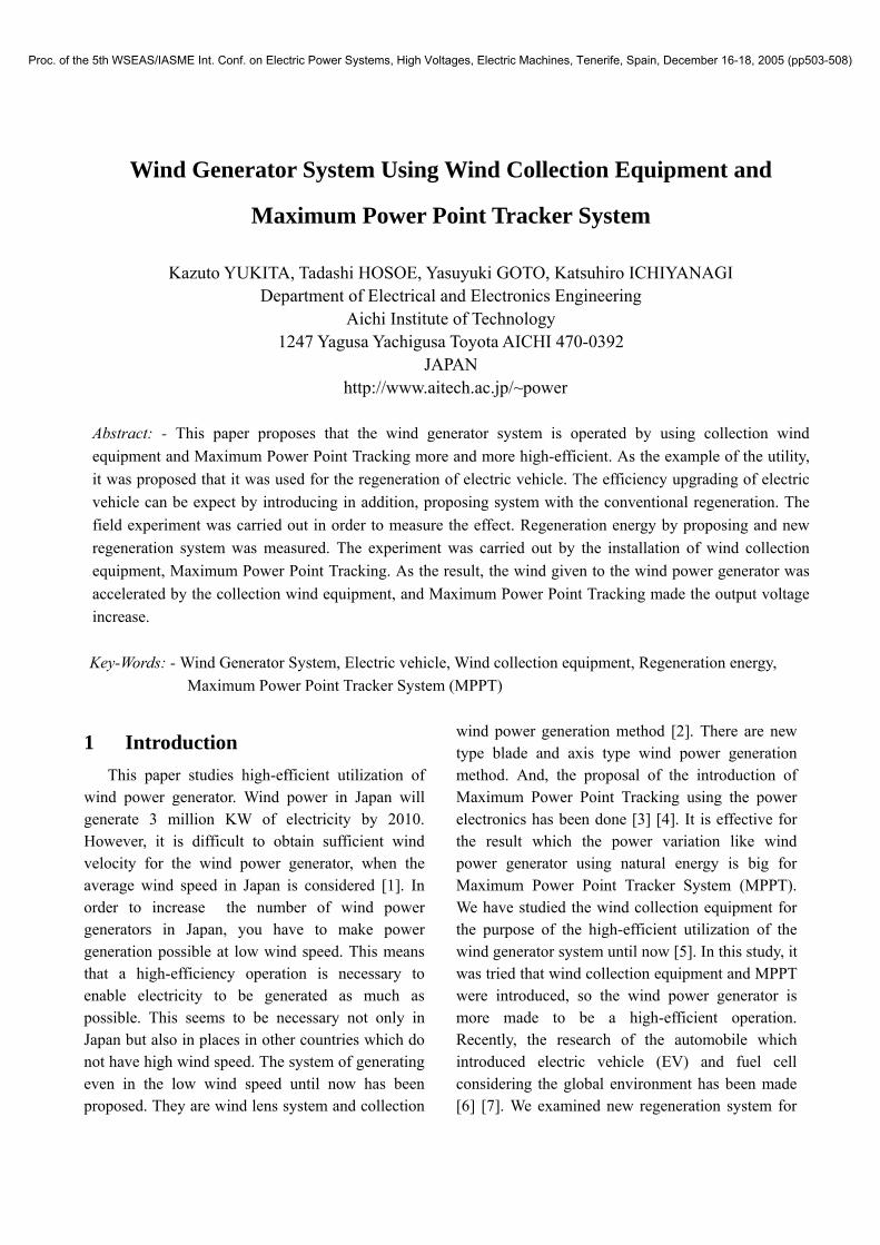
The theoretical energy P which the wind possesses is proportional to the cube of the wind velocity. And P is proportional to aerial density and wind receiving area also as shown in (1). If we can double the wind velocity, it is anticipated that the energy generated will be 8 times that produced from the undouble velocity. The high-efficient utilization of the wind power generator can be carried out by installing the wind collection equipment. Wind collection equipment examined until now is shown fig.1. This equipment was designed for the small wind power generator. Fig.1. Wind Collection Equipment (Expanded type)
It is the shape (Expanded type) which was the most effective in simulation and field trial.
3 Maximum Power Point
Tracking System Output of the wind power generator fluctuates
by load and rotational frequency. The rotational frequency fluctuates by the speed of the automobile, and output of the wind power generator always fluctuates when wind power generator was used for regeneration of electric vehicle. The speed of the automobile is low-speed from the high speed or stops from the low speed when regeneration. The wind velocity gets in proportion to the speed of the automobile changes. Then, regeneration energy by the wind power generator can be efficiently taken out by using MPPT. MPPT used in this study proposed the thing of the compact because, the small wind power generator mounted electric vehicle can be mounted. The system was examined between using integrated circuit and high-speed semiconductor element IGBT in this study in MPPT in wind power generator. 3.1 Maximum Power Point Tracking Method
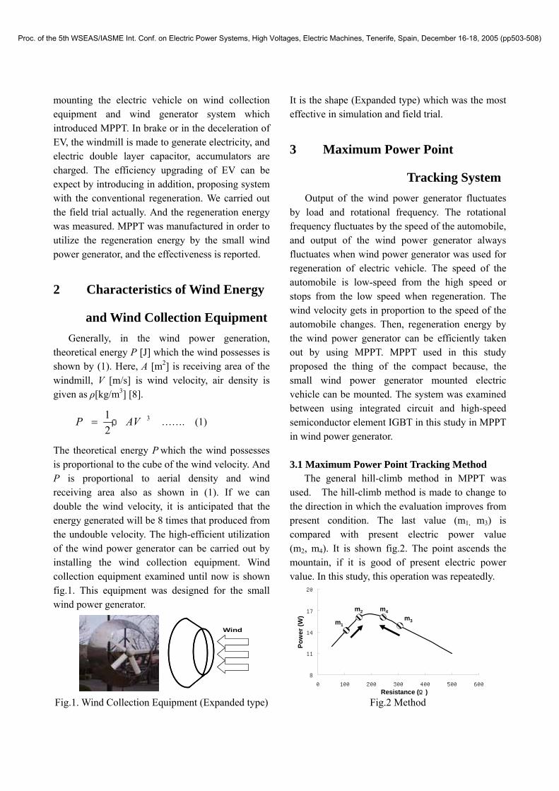
The general hill-climb method in MPPT was used. The hill-climb method is made to change to the direction in which the evaluation improves from present condition. The last value (m1, m3) is compared with present electric power value (m2, m4). It is shown fig.2. The point ascends the mountain, if it is good of present electric power value. In this study, this operation was repeatedly.
Fig.2 Method
Wind
8
11
14
17
20
0 100 200 300 400 500 600
m2
m1m3
m4
Resistance (Ω)
Pow
er(W
)
Proc. of the 5th WSEAS/IASME Int. Conf. on Electric Power Systems, High Voltages, Electric Machines, Tenerife, Spain, December 16-18, 2005 (pp503-508)
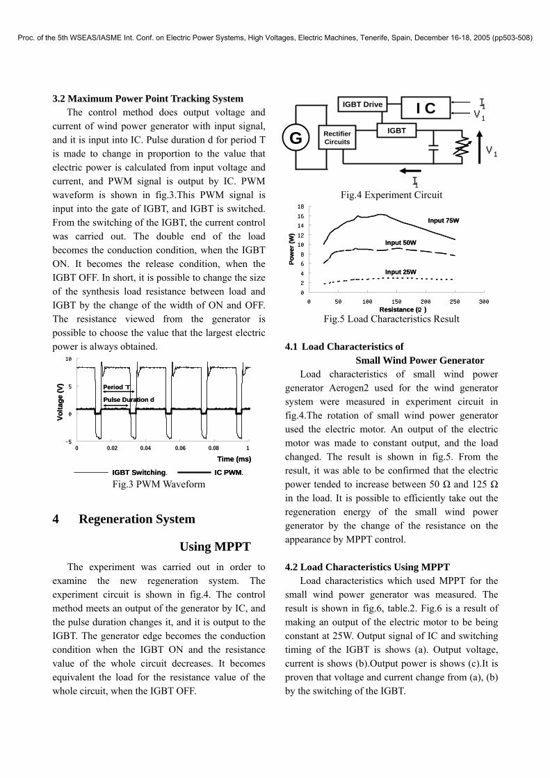
3.2 Maximum Power Point Tracking System The control method does output voltage and
current of wind power generator with input signal, and it is input into IC. Pulse duration d for period T is made to change in proportion to the value that electric power is calculated from input voltage and current, and PWM signal is output by IC. PWM waveform is shown in fig.3.This PWM signal is input into the gate of IGBT, and IGBT is switched. From the switching of the IGBT, the current control was carried out. The double end of the load becomes the conduction condition, when the IGBT ON. It becomes the release condition, when the IGBT OFF. In short, it is possible to change the size of the synthesis load resistance between load and IGBT by the change of the width of ON and OFF. The resistance viewed from the generator is possible to choose the value that the largest electric power is always obtained.
Fig.3 PWM Waveform
4 Regeneration System
Using MPPT The experiment was carried out in order to
examine the new regeneration system. The experiment circuit is shown in fig.4. The control method meets an output of the generator by IC, and the pulse duration changes it, and it is output to the IGBT. The generator edge becomes the conduction condition when the IGBT ON and the resistance value of the whole circuit decreases. It becomes equivalent the load for the resistance value of the whole circuit, when the IGBT OFF.
Fig.4 Experiment Circuit
Fig.5 Load Characteristics Result 4.1 Load Characteristics of
Small Wind Power Generator Load characteristics of small wind power
generator Aerogen2 used for the wind generator system were measured in experiment circuit in fig.4.The rotation of small wind power generator used the electric motor. An output of the electric motor was made to constant output, and the load changed. The result is shown in fig.5. From the result, it was able to be confirmed that the electric power tended to increase between 50 Ω and 125 Ω in the load. It is possible to efficiently take out the regeneration energy of the small wind power generator by the change of the resistance on the appearance by MPPT control. 4.2 Load Characteristics Using MPPT
Load characteristics which used MPPT for the small wind power generator was measured. The result is shown in fig.6, table.2. Fig.6 is a result of making an output of the electric motor to be being constant at 25W. Output signal of IC and switching timing of the IGBT is shows (a). Output voltage, current is shows (b).Output power is shows (c).It is proven that voltage and current change from (a), (b) by the switching of the IGBT.
G RectifierCircuits
IGBT
I1
V1
IGBT Drive I C I1V1
0
2
4
6
8
10
12
14
16
18
0 50 100 150 200 250 300
Resistance (Ω)
Pow
er(W
)
Input 75W
Input 50W
Input 25W
0
2
4
6
8
10
12
14
16
18
0 50 100 150 200 250 300
Resistance (Ω)
Pow
er(W
)
Input 75W
Input 50W
Input 25W
Time (ms)
Volta
ge (V
)
-5
0
5
10
0 0.2 0.4 0.6 0.8 1
Period T
Pulse Duration d
IGBT Switching. IC PWM.
0 0.02 0.04 0.06 0.08 1
Time (ms)
Volta
ge (V
)
-5
0
5
10
0 0.2 0.4 0.6 0.8 1
Period T
Pulse Duration d
IGBT Switching. IC PWM.
0 0.02 0.04 0.06 0.08 1
Proc. of the 5th WSEAS/IASME Int. Conf. on Electric Power Systems, High Voltages, Electric Machines, Tenerife, Spain, December 16-18, 2005 (pp503-508)
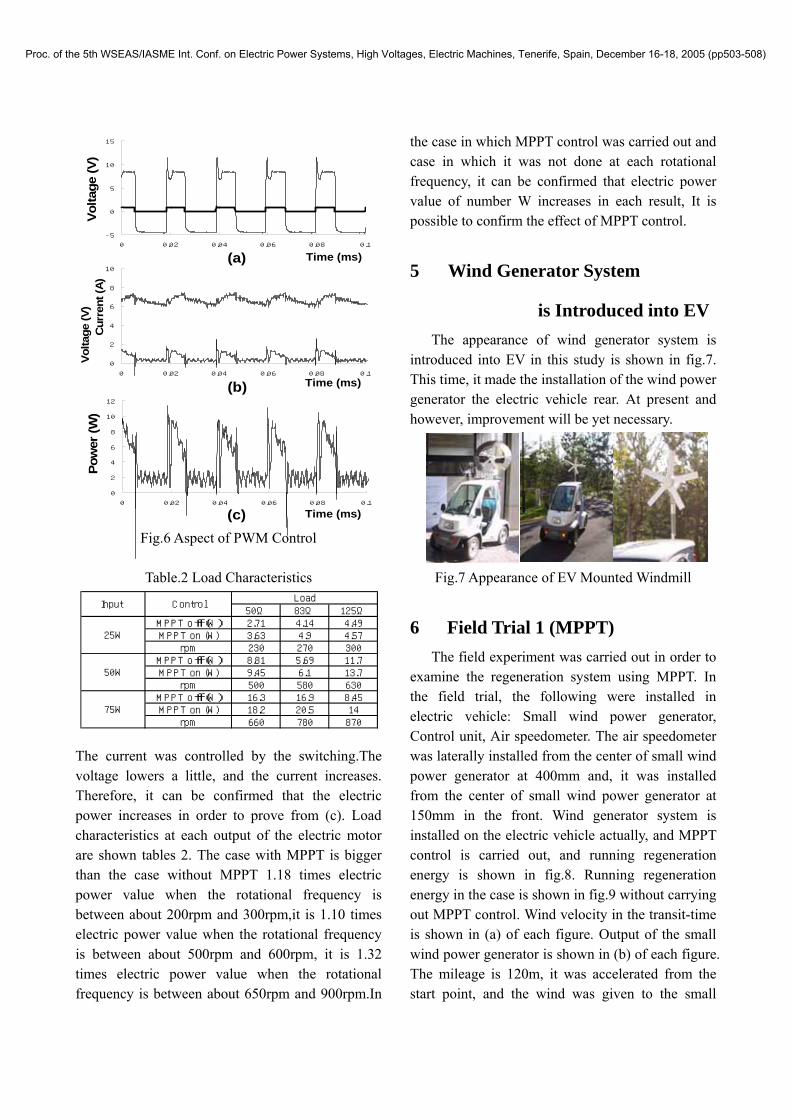
Fig.6 Aspect of PWM Control
Table.2 Load Characteristics The current was controlled by the switching.The voltage lowers a little, and the current increases. Therefore, it can be confirmed that the electric power increases in order to prove from (c). Load characteristics at each output of the electric motor are shown tables 2. The case with MPPT is bigger than the case without MPPT 1.18 times electric power value when the rotational frequency is between about 200rpm and 300rpm,it is 1.10 times electric power value when the rotational frequency is between about 500rpm and 600rpm, it is 1.32 times electric power value when the rotational frequency is between about 650rpm and 900rpm.In
the case in which MPPT control was carried out and case in which it was not done at each rotational frequency, it can be confirmed that electric power value of number W increases in each result, It is possible to confirm the effect of MPPT control.
5 Wind Generator System
is Introduced into EV The appearance of wind generator system is
introduced into EV in this study is shown in fig.7. This time, it made the installation of the wind power generator the electric vehicle rear. At present and however, improvement will be yet necessary.
Fig.7 Appearance of EV Mounted Windmill
6 Field Trial 1 (MPPT) The field experiment was carried out in order to
examine the regeneration system using MPPT. In the field trial, the following were installed in electric vehicle: Small wind power generator, Control unit, Air speedometer. The air speedometer was laterally installed from the center of small wind power generator at 400mm and, it was installed from the center of small wind power generator at 150mm in the front. Wind generator system is installed on the electric vehicle actually, and MPPT control is carried out, and running regeneration energy is shown in fig.8. Running regeneration energy in the case is shown in fig.9 without carrying out MPPT control. Wind velocity in the transit-time is shown in (a) of each figure. Output of the small wind power generator is shown in (b) of each figure. The mileage is 120m, it was accelerated from the start point, and the wind was given to the small
0
2
4
6
8
10
0 0.02 0.04 0.06 0.08 0.1
0
2
4
6
8
10
12
0 0.02 0.04 0.06 0.08 0.1
-5
0
5
10
15
0 0.02 0.04 0.06 0.08 0.1
Pow
er(W
)Vo
ltage
(V)
Cur
rent
(A)
Volta
ge (V
)
Time (ms)
Time (ms)
Time (ms)
(a)
(b)
(c)
50Ω 83Ω 125Ω
MPPT off (W) 2.71 4.14 4.49MPPT on (W) 3.63 4.9 4.57rpm 230 270 300
MPPT off (W) 8.81 5.69 11.7MPPT on (W) 9.45 6.1 13.7rpm 500 580 630
MPPT off (W) 16.3 16.9 8.45MPPT on (W) 18.2 20.5 14rpm 660 780 870
50W
75W
Input ControlLoad
25W
Proc. of the 5th WSEAS/IASME Int. Conf. on Electric Power Systems, High Voltages, Electric Machines, Tenerife, Spain, December 16-18, 2005 (pp503-508)
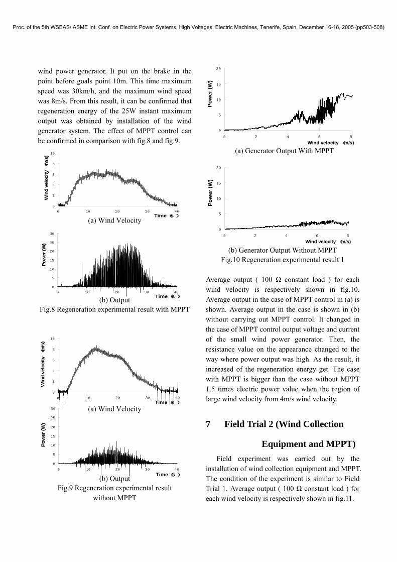
wind power generator. It put on the brake in the point before goals point 10m. This time maximum speed was 30km/h, and the maximum wind speed was 8m/s. From this result, it can be confirmed that regeneration energy of the 25W instant maximum output was obtained by installation of the wind generator system. The effect of MPPT control can be confirmed in comparison with fig.8 and fig.9.
(a) Wind Velocity
(b) Output Fig.8 Regeneration experimental result with MPPT
(a) Wind Velocity
(b) Output Fig.9 Regeneration experimental result
without MPPT
(a) Generator Output With MPPT
(b) Generator Output Without MPPT Fig.10 Regeneration experimental result 1
Average output ( 100 Ω constant load ) for each wind velocity is respectively shown in fig.10. Average output in the case of MPPT control in (a) is shown. Average output in the case is shown in (b) without carrying out MPPT control. It changed in the case of MPPT control output voltage and current of the small wind power generator. Then, the resistance value on the appearance changed to the way where power output was high. As the result, it increased of the regeneration energy get. The case with MPPT is bigger than the case without MPPT 1.5 times electric power value when the region of large wind velocity from 4m/s wind velocity.
7 Field Trial 2 (Wind Collection
Equipment and MPPT) Field experiment was carried out by the
installation of wind collection equipment and MPPT. The condition of the experiment is similar to Field Trial 1. Average output ( 100 Ω constant load ) for each wind velocity is respectively shown in fig.11.
0
5
10
15
20
25
30
0 10 20 30 40
Pow
er (W
)
Time (s )
0
5
10
15
20
0 2 4 6 8
Pow
er (W
)
Wind velocity (m/s)
0
5
10
15
20
0 2 4 6 8
Pow
er (W
)
Wind velocity (m/s)
Pow
er (W
)
Time (s )
0
5
10
15
20
25
30
0 10 20 30 40
Win
d ve
loci
ty(m
/s)
Time (s )
0
2
4
6
8
10
0 10 20 30 40
Win
d ve
loci
ty(m
/s)
Time (s )
0
2
4
6
8
10
0 10 20 30 40
Proc. of the 5th WSEAS/IASME Int. Conf. on Electric Power Systems, High Voltages, Electric Machines, Tenerife, Spain, December 16-18, 2005 (pp503-508)
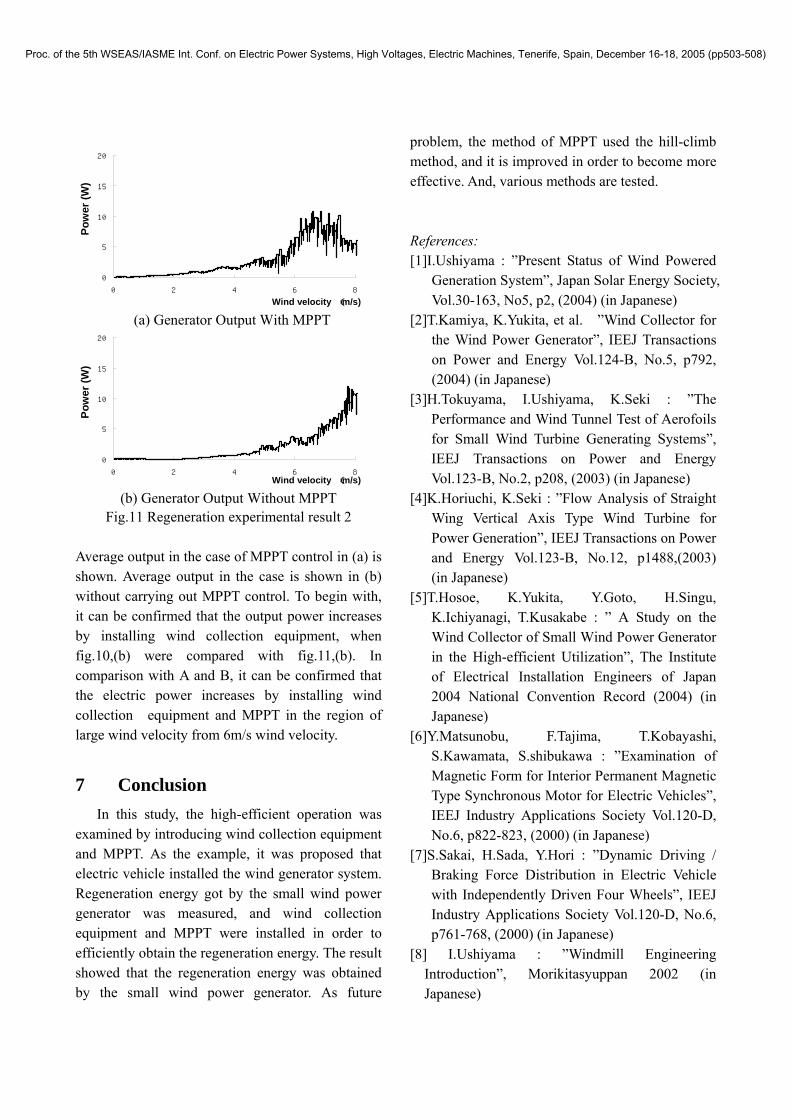
(a) Generator Output With MPPT
(b) Generator Output Without MPPT Fig.11 Regeneration experimental result 2
Average output in the case of MPPT control in (a) is shown. Average output in the case is shown in (b) without carrying out MPPT control. To begin with, it can be confirmed that the output power increases by installing wind collection equipment, when fig.10,(b) were compared with fig.11,(b). In comparison with A and B, it can be confirmed that the electric power increases by installing wind collection equipment and MPPT in the region of large wind velocity from 6m/s wind velocity.
7 Conclusion In this study, the high-efficient operation was
examined by introducing wind collection equipment and MPPT. As the example, it was proposed that electric vehicle installed the wind generator system. Regeneration energy got by the small wind power generator was measured, and wind collection equipment and MPPT were installed in order to efficiently obtain the regeneration energy. The result showed that the regeneration energy was obtained by the small wind power generator. As future
problem, the method of MPPT used the hill-climb method, and it is improved in order to become more effective. And, various methods are tested. References: [1]I.Ushiyama : ”Present Status of Wind Powered
Generation System”, Japan Solar Energy Society, Vol.30-163, No5, p2, (2004) (in Japanese)
[2]T.Kamiya, K.Yukita, et al. ”Wind Collector for the Wind Power Generator”, IEEJ Transactions on Power and Energy Vol.124-B, No.5, p792, (2004) (in Japanese)
[3]H.Tokuyama, I.Ushiyama, K.Seki : ”The Performance and Wind Tunnel Test of Aerofoils for Small Wind Turbine Generating Systems”, IEEJ Transactions on Power and Energy Vol.123-B, No.2, p208, (2003) (in Japanese)
[4]K.Horiuchi, K.Seki : ”Flow Analysis of Straight Wing Vertical Axis Type Wind Turbine for Power Generation”, IEEJ Transactions on Power and Energy Vol.123-B, No.12, p1488,(2003) (in Japanese)
[5]T.Hosoe, K.Yukita, Y.Goto, H.Singu, K.Ichiyanagi, T.Kusakabe : ” A Study on the Wind Collector of Small Wind Power Generator in the High-efficient Utilization”, The Institute of Electrical Installation Engineers of Japan 2004 National Convention Record (2004) (in Japanese)
[6]Y.Matsunobu, F.Tajima, T.Kobayashi, S.Kawamata, S.shibukawa : ”Examination of Magnetic Form for Interior Permanent Magnetic Type Synchronous Motor for Electric Vehicles”, IEEJ Industry Applications Society Vol.120-D, No.6, p822-823, (2000) (in Japanese)
[7]S.Sakai, H.Sada, Y.Hori : ”Dynamic Driving / Braking Force Distribution in Electric Vehicle with Independently Driven Four Wheels”, IEEJ Industry Applications Society Vol.120-D, No.6, p761-768, (2000) (in Japanese)
[8] I.Ushiyama : ”Windmill Engineering Introduction”, Morikitasyuppan 2002 (in Japanese)
0
5
10
15
20
0 2 4 6 8
Pow
er (W
)
Wind velocity (m/s)
0
5
10
15
20
0 2 4 6 8
Pow
er (W
)
Wind velocity (m/s)
Proc. of the 5th WSEAS/IASME Int. Conf. on Electric Power Systems, High Voltages, Electric Machines, Tenerife, Spain, December 16-18, 2005 (pp503-508)