Embed Size (px)
Citation preview
Smart Grid and Renewable Energy, 2010, 1, 119-131 doi:10.4236/sgre.2010.13017 Published Online November 2010 (http://www.SciRP.org/journal/sgre)
Copyright © 2010 SciRes. SGRE
119
Wind Energy Conversion System from Electrical Perspective —A Survey
Hyong Sik Kim, Dylan Dah-Chuan Lu
School of Electrical and Information Engineering, University of Sydney, Sydney, Australia Email: [email protected] Received October 20th, 2010; revised November 14th, 2010; accepted November 20th, 2010
ABSTRACT
This paper focuses on the wind energy conversion system (WECS) with the three main electrical aspects: 1) wind tur-bine generators (WTGs), 2) power electronics converters (PECs) and 3) grid-connection issues. The current state of wind turbine generators are discussed and compared in some criteria along with the trends in the current WECS mar-ket, which are ‘Variable Speed’, ‘Multi-MW’ and ‘Offshore’. In addition, the other crucial component in the WECS, PECs will be discussed with its topologies available in the current WECS market along with their modulation strategies. Moreover, three main issues of the WECS associating with the grid-connection, fault-ride through (FRT) capability, harmonics/interharmonics emission and flicker, which are the power quality issues, will be discussed due to the in-creasing responsibility of WECS as utility power station. Some key findings from the review such as the attractiveness of BDFRG are presented in the conclusion of this paper. Keywords: Wind Energy, Wind Turbine Generators, Power Electronic Converters, Grid-Connection, Brushless,
Reluctance, Pulse-Width Modulation, Fault Ride Through Capability, Voltage Dip, Harmonics, Flicker, Power Quality, BDFRG
1. Introduction
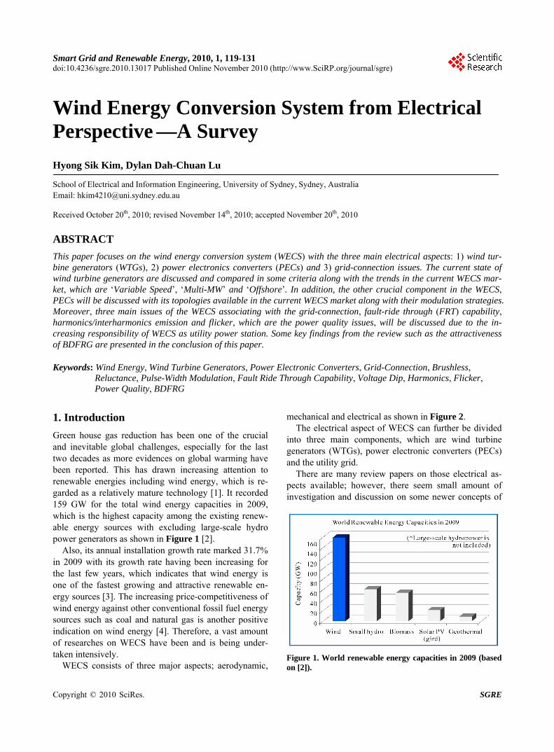
Green house gas reduction has been one of the crucial and inevitable global challenges, especially for the last two decades as more evidences on global warming have been reported. This has drawn increasing attention to renewable energies including wind energy, which is re-garded as a relatively mature technology [1]. It recorded 159 GW for the total wind energy capacities in 2009, which is the highest capacity among the existing renew-able energy sources with excluding large-scale hydro power generators as shown in Figure 1 [2].
Also, its annual installation growth rate marked 31.7% in 2009 with its growth rate having been increasing for the last few years, which indicates that wind energy is one of the fastest growing and attractive renewable en-ergy sources [3]. The increasing price-competitiveness of wind energy against other conventional fossil fuel energy sources such as coal and natural gas is another positive indication on wind energy [4]. Therefore, a vast amount of researches on WECS have been and is being under-taken intensively.
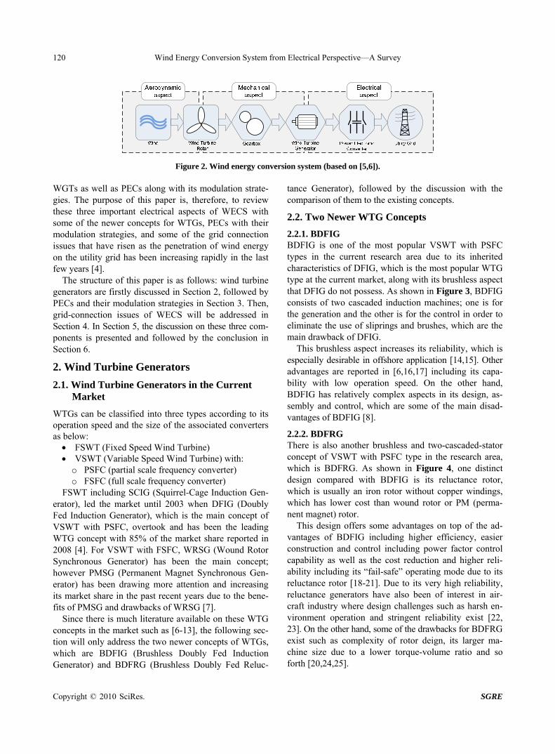
WECS consists of three major aspects; aerodynamic,
mechanical and electrical as shown in Figure 2. The electrical aspect of WECS can further be divided
into three main components, which are wind turbine generators (WTGs), power electronic converters (PECs) and the utility grid.
There are many review papers on those electrical as-pects available; however, there seem small amount of investigation and discussion on some newer concepts of
Figure 1. World renewable energy capacities in 2009 (based on [2]).
Wind Energy Conversion System from Electrical Perspective—A Survey
Copyright © 2010 SciRes. SGRE
120
Figure 2. Wind energy conversion system (based on [5,6]). WGTs as well as PECs along with its modulation strate-gies. The purpose of this paper is, therefore, to review these three important electrical aspects of WECS with some of the newer concepts for WTGs, PECs with their modulation strategies, and some of the grid connection issues that have risen as the penetration of wind energy on the utility grid has been increasing rapidly in the last few years [4].
The structure of this paper is as follows: wind turbine generators are firstly discussed in Section 2, followed by PECs and their modulation strategies in Section 3. Then, grid-connection issues of WECS will be addressed in Section 4. In Section 5, the discussion on these three com-ponents is presented and followed by the conclusion in Section 6.
2. Wind Turbine Generators
2.1. Wind Turbine Generators in the Current Market
WTGs can be classified into three types according to its operation speed and the size of the associated converters as below: FSWT (Fixed Speed Wind Turbine) VSWT (Variable Speed Wind Turbine) with:
o PSFC (partial scale frequency converter) o FSFC (full scale frequency converter)
FSWT including SCIG (Squirrel-Cage Induction Gen-erator), led the market until 2003 when DFIG (Doubly Fed Induction Generator), which is the main concept of VSWT with PSFC, overtook and has been the leading WTG concept with 85% of the market share reported in 2008 [4]. For VSWT with FSFC, WRSG (Wound Rotor Synchronous Generator) has been the main concept; however PMSG (Permanent Magnet Synchronous Gen-erator) has been drawing more attention and increasing its market share in the past recent years due to the bene-fits of PMSG and drawbacks of WRSG [7].
Since there is much literature available on these WTG concepts in the market such as [6-13], the following sec-tion will only address the two newer concepts of WTGs, which are BDFIG (Brushless Doubly Fed Induction Generator) and BDFRG (Brushless Doubly Fed Reluc-
tance Generator), followed by the discussion with the comparison of them to the existing concepts.
2.2. Two Newer WTG Concepts
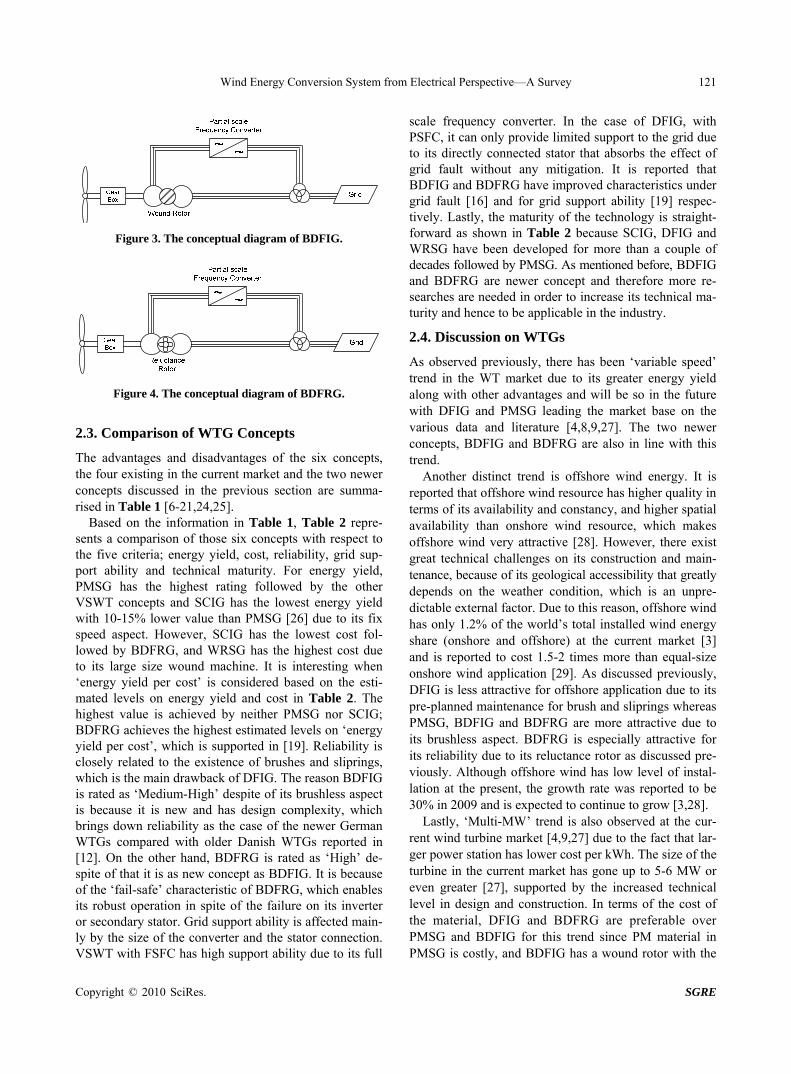
2.2.1. BDFIG BDFIG is one of the most popular VSWT with PSFC types in the current research area due to its inherited characteristics of DFIG, which is the most popular WTG type at the current market, along with its brushless aspect that DFIG do not possess. As shown in Figure 3, BDFIG consists of two cascaded induction machines; one is for the generation and the other is for the control in order to eliminate the use of sliprings and brushes, which are the main drawback of DFIG.
This brushless aspect increases its reliability, which is especially desirable in offshore application [14,15]. Other advantages are reported in [6,16,17] including its capa-bility with low operation speed. On the other hand, BDFIG has relatively complex aspects in its design, as-sembly and control, which are some of the main disad-vantages of BDFIG [8].
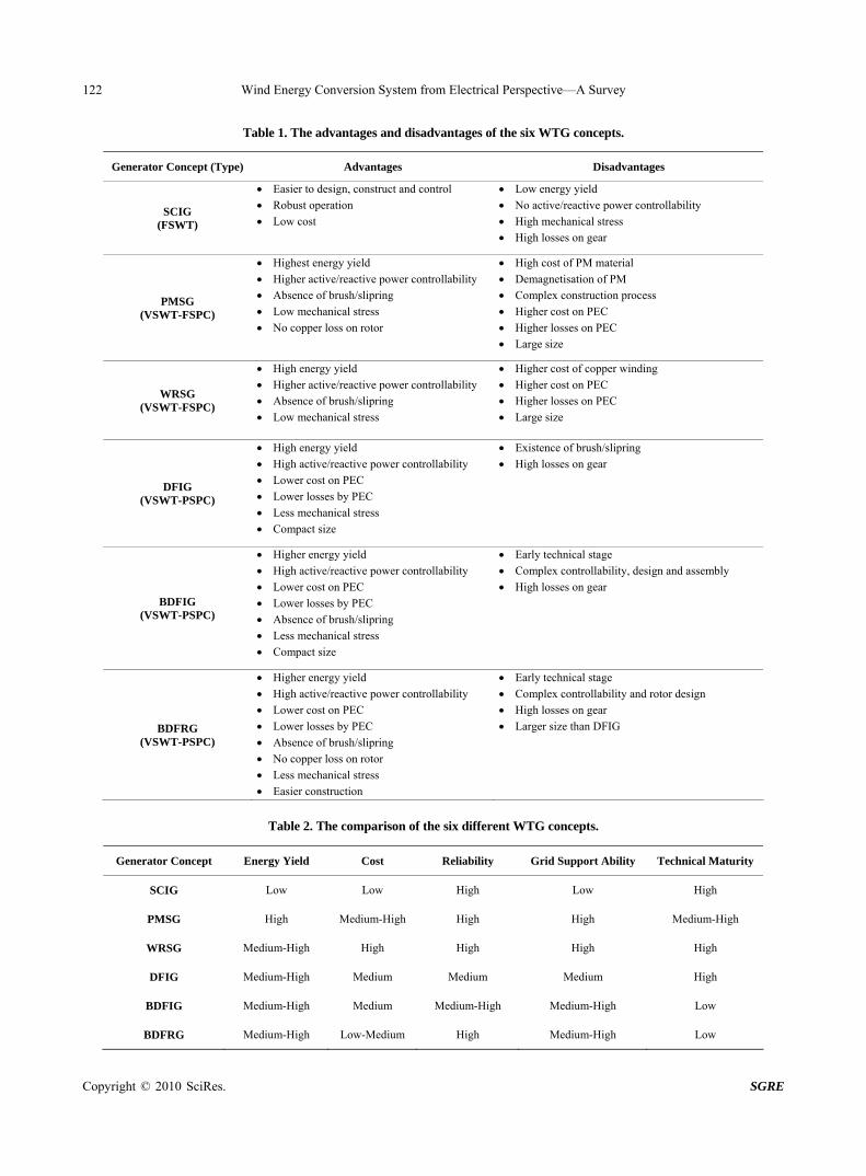
2.2.2. BDFRG There is also another brushless and two-cascaded-stator concept of VSWT with PSFC type in the research area, which is BDFRG. As shown in Figure 4, one distinct design compared with BDFIG is its reluctance rotor, which is usually an iron rotor without copper windings, which has lower cost than wound rotor or PM (perma-nent magnet) rotor.
This design offers some advantages on top of the ad-vantages of BDFIG including higher efficiency, easier construction and control including power factor control capability as well as the cost reduction and higher reli-ability including its “fail-safe” operating mode due to its reluctance rotor [18-21]. Due to its very high reliability, reluctance generators have also been of interest in air-craft industry where design challenges such as harsh en-vironment operation and stringent reliability exist [22, 23]. On the other hand, some of the drawbacks for BDFRG exist such as complexity of rotor deign, its larger ma-chine size due to a lower torque-volume ratio and so forth [20,24,25].
Wind Energy Conversion System from Electrical Perspective—A Survey
Copyright © 2010 SciRes. SGRE
121
Figure 3. The conceptual diagram of BDFIG.
Figure 4. The conceptual diagram of BDFRG.
2.3. Comparison of WTG Concepts
The advantages and disadvantages of the six concepts, the four existing in the current market and the two newer concepts discussed in the previous section are summa-rised in Table 1 [6-21,24,25].
Based on the information in Table 1, Table 2 repre-sents a comparison of those six concepts with respect to the five criteria; energy yield, cost, reliability, grid sup-port ability and technical maturity. For energy yield, PMSG has the highest rating followed by the other VSWT concepts and SCIG has the lowest energy yield with 10-15% lower value than PMSG [26] due to its fix speed aspect. However, SCIG has the lowest cost fol-lowed by BDFRG, and WRSG has the highest cost due to its large size wound machine. It is interesting when ‘energy yield per cost’ is considered based on the esti-mated levels on energy yield and cost in Table 2. The highest value is achieved by neither PMSG nor SCIG; BDFRG achieves the highest estimated levels on ‘energy yield per cost’, which is supported in [19]. Reliability is closely related to the existence of brushes and sliprings, which is the main drawback of DFIG. The reason BDFIG is rated as ‘Medium-High’ despite of its brushless aspect is because it is new and has design complexity, which brings down reliability as the case of the newer German WTGs compared with older Danish WTGs reported in [12]. On the other hand, BDFRG is rated as ‘High’ de-spite of that it is as new concept as BDFIG. It is because of the ‘fail-safe’ characteristic of BDFRG, which enables its robust operation in spite of the failure on its inverter or secondary stator. Grid support ability is affected main- ly by the size of the converter and the stator connection. VSWT with FSFC has high support ability due to its full
scale frequency converter. In the case of DFIG, with PSFC, it can only provide limited support to the grid due to its directly connected stator that absorbs the effect of grid fault without any mitigation. It is reported that BDFIG and BDFRG have improved characteristics under grid fault [16] and for grid support ability [19] respec-tively. Lastly, the maturity of the technology is straight-forward as shown in Table 2 because SCIG, DFIG and WRSG have been developed for more than a couple of decades followed by PMSG. As mentioned before, BDFIG and BDFRG are newer concept and therefore more re-searches are needed in order to increase its technical ma-turity and hence to be applicable in the industry.
2.4. Discussion on WTGs
As observed previously, there has been ‘variable speed’ trend in the WT market due to its greater energy yield along with other advantages and will be so in the future with DFIG and PMSG leading the market base on the various data and literature [4,8,9,27]. The two newer concepts, BDFIG and BDFRG are also in line with this trend.
Another distinct trend is offshore wind energy. It is reported that offshore wind resource has higher quality in terms of its availability and constancy, and higher spatial availability than onshore wind resource, which makes offshore wind very attractive [28]. However, there exist great technical challenges on its construction and main-tenance, because of its geological accessibility that greatly depends on the weather condition, which is an unpre-dictable external factor. Due to this reason, offshore wind has only 1.2% of the world’s total installed wind energy share (onshore and offshore) at the current market [3] and is reported to cost 1.5-2 times more than equal-size onshore wind application [29]. As discussed previously, DFIG is less attractive for offshore application due to its pre-planned maintenance for brush and sliprings whereas PMSG, BDFIG and BDFRG are more attractive due to its brushless aspect. BDFRG is especially attractive for its reliability due to its reluctance rotor as discussed pre-viously. Although offshore wind has low level of instal-lation at the present, the growth rate was reported to be 30% in 2009 and is expected to continue to grow [3,28].
Lastly, ‘Multi-MW’ trend is also observed at the cur-rent wind turbine market [4,9,27] due to the fact that lar-ger power station has lower cost per kWh. The size of the turbine in the current market has gone up to 5-6 MW or even greater [27], supported by the increased technical level in design and construction. In terms of the cost of the material, DFIG and BDFRG are preferable over PMSG and BDFIG for this trend since PM material in PMSG is costly, and BDFIG has a wound rotor with the
Wind Energy Conversion System from Electrical Perspective—A Survey
Copyright © 2010 SciRes. SGRE
122
Table 1. The advantages and disadvantages of the six WTG concepts.
Generator Concept (Type) Advantages Disadvantages
SCIG (FSWT)
Easier to design, construct and control
Robust operation
Low cost
Low energy yield
No active/reactive power controllability
High mechanical stress
High losses on gear
PMSG (VSWT-FSPC)
Highest energy yield
Higher active/reactive power controllability
Absence of brush/slipring
Low mechanical stress
No copper loss on rotor
High cost of PM material
Demagnetisation of PM
Complex construction process
Higher cost on PEC
Higher losses on PEC
Large size
WRSG (VSWT-FSPC)
High energy yield
Higher active/reactive power controllability
Absence of brush/slipring
Low mechanical stress
Higher cost of copper winding
Higher cost on PEC
Higher losses on PEC
Large size
DFIG (VSWT-PSPC)
High energy yield
High active/reactive power controllability
Lower cost on PEC
Lower losses by PEC
Less mechanical stress
Compact size
Existence of brush/slipring
High losses on gear
BDFIG (VSWT-PSPC)
Higher energy yield
High active/reactive power controllability
Lower cost on PEC
Lower losses by PEC
Absence of brush/slipring
Less mechanical stress
Compact size
Early technical stage
Complex controllability, design and assembly
High losses on gear
BDFRG (VSWT-PSPC)
Higher energy yield
High active/reactive power controllability
Lower cost on PEC
Lower losses by PEC
Absence of brush/slipring
No copper loss on rotor
Less mechanical stress
Easier construction
Early technical stage
Complex controllability and rotor design
High losses on gear
Larger size than DFIG
Table 2. The comparison of the six different WTG concepts.
Generator Concept Energy Yield Cost Reliability Grid Support Ability Technical Maturity
SCIG Low Low High Low High
PMSG High Medium-High High High Medium-High
WRSG Medium-High High High High High
DFIG Medium-High Medium Medium Medium High
BDFIG Medium-High Medium Medium-High Medium-High Low
BDFRG Medium-High Low-Medium High Medium-High Low
Wind Energy Conversion System from Electrical Perspective—A Survey
Copyright © 2010 SciRes. SGRE
123
two wound cascaded stator, which has greater amount of windings than DFIG or BDFRG.
3. Power Electronic Converters
3.1. Topology of Power Electronic Converters
As the amount of the installed VSWT increased, so has the importance of PECs in WECS since it is the interface between WTGs and the electrical grid [1,11,30]. There are three types of converters widely available in the cur-rent wind energy market: Back-to-back PWM converter, multilevel converter and matrix converter.
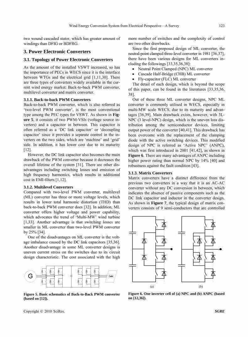
3.1.1. Back-to-back PWM Converters Back-to-back PWM converter, which is also referred as ‘two-level PWM converter’, is the most conventional type among the PEC types for VSWT. As shown in Fig-ure 5, it consists of two PWM-VSIs (voltage source in-verters) and a capacitor in between. This capacitor is often referred as a ‘DC link capacitor’ or ‘decoupling capacitor’ since it provides a separate control in the in-verters on the two sides, which are ‘machine’ and ‘grid’ side. In addition, it has lower cost due to its maturity [12].
However, the DC link capacitor also becomes the main drawback of the PWM converter because it decreases the overall lifetime of the system [31]. There are other dis-advantages including switching losses and emission of high frequency harmonics, which results in additional cost in EMI-filters [1,12].
3.1.2. Multilevel Converters Compared with two-level PWM converter, multilevel (ML) converter has three or more voltage levels, which results in lower total harmonic distortion (THD) than back-to-back PWM converter does [32]. In addition, ML converter offers higher voltage and power capability, which advocates the trend of ‘Multi-MW’ wind turbine [1,33]. Another advantage is that switching losses are smaller in ML converter than two-level PWM converter by 25% [34].
One of the disadvantages on ML converter is the volt-age imbalance caused by the DC link capacitors [35,36]. Another disadvantage in some ML converter designs is uneven current stress on the switches due to its circuit design characteristic. The cost associated with the high
Figure 5. Basic schematics of Back-to-Back PWM converter (based on [12]).
more number of switches and the complexity of control are two other drawbacks.
Since the first proposed design of ML converter, the neutral-point clamped three-level converter in 1981 [36,37], there have been various designs for ML converters in-cluding the followings [33,35,36,38]: Neutral Point Clamped (NPC) ML converter Cascade Half-Bridge (CHB) ML converter Fly-capacitor (FLC) ML converter The detail of each design, which is beyond the scope
of this paper, can be found in the literatures [33,35,36, 38].
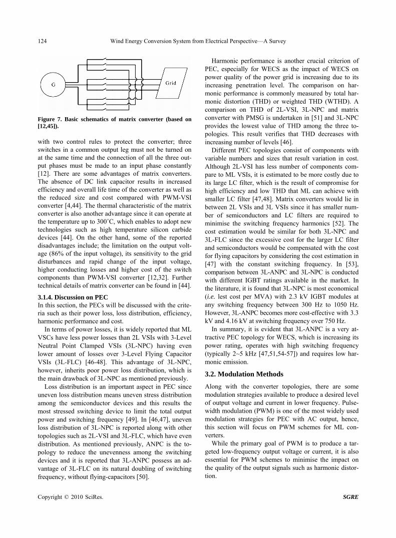
Out of these three ML converter designs, NPC ML converter is commonly utilised in WECS, especially in multi-MW scale WECS, due to its maturity and advan-tages [36,39]. Main drawback exists, however, with 3L- NPC (3 level-NPC) design, which is the uneven loss dis-tribution among the semiconductor devices, limiting output power of the converter [40,41]. This drawback has been overcome with the replacement of the clamping diode with the active switching devices. This modified design of NPC is referred as ‘Active NPC’ (ANPC), which was first introduced in 2001 [41,42], as shown in Figure 6. There are many advantages of ANPC including higher power rating than normal NPC by 14% [40] and robustness against the fault condition [43].
3.1.3. Matrix Converters Matrix converters have a distinct difference from the previous two converters in a way that it is an AC-AC converter without any DC conversion in between, which indicates the absence of passive components such as the DC link capacitor and inductor in the converter design. As shown in Figure 7, the typical design of matrix con-verters consists of 9 semi-conductors that are controlled
(a) (b)
Figure 6. One inverter cell of (a) NPC and (b) ANPC (based on [12,36]).
Wind Energy Conversion System from Electrical Perspective—A Survey
Copyright © 2010 SciRes. SGRE
124
Figure 7. Basic schematics of matrix converter (based on [12,45]). with two control rules to protect the converter; three switches in a common output leg must not be turned on at the same time and the connection of all the three out-put phases must be made to an input phase constantly [12]. There are some advantages of matrix converters. The absence of DC link capacitor results in increased efficiency and overall life time of the converter as well as the reduced size and cost compared with PWM-VSI converter [4,44]. The thermal characteristic of the matrix converter is also another advantage since it can operate at the temperature up to 300˚C, which enables to adopt new technologies such as high temperature silicon carbide devices [44]. On the other hand, some of the reported disadvantages include; the limitation on the output volt-age (86% of the input voltage), its sensitivity to the grid disturbances and rapid change of the input voltage, higher conducting losses and higher cost of the switch components than PWM-VSI converter [12,32]. Further technical details of matrix converter can be found in [44].
3.1.4. Discussion on PEC In this section, the PECs will be discussed with the crite-ria such as their power loss, loss distribution, efficiency, harmonic performance and cost.
In terms of power losses, it is widely reported that ML VSCs have less power losses than 2L VSIs with 3-Level Neutral Point Clamped VSIs (3L-NPC) having even lower amount of losses over 3-Level Flying Capacitor VSIs (3L-FLC) [46-48]. This advantage of 3L-NPC, however, inherits poor power loss distribution, which is the main drawback of 3L-NPC as mentioned previously.
Loss distribution is an important aspect in PEC since uneven loss distribution means uneven stress distribution among the semiconductor devices and this results the most stressed switching device to limit the total output power and switching frequency [49]. In [46,47], uneven loss distribution of 3L-NPC is reported along with other topologies such as 2L-VSI and 3L-FLC, which have even distribution. As mentioned previously, ANPC is the to-pology to reduce the unevenness among the switching devices and it is reported that 3L-ANPC possess an ad-vantage of 3L-FLC on its natural doubling of switching frequency, without flying-capacitors [50].
Harmonic performance is another crucial criterion of PEC, especially for WECS as the impact of WECS on power quality of the power grid is increasing due to its increasing penetration level. The comparison on har-monic performance is commonly measured by total har-monic distortion (THD) or weighted THD (WTHD). A comparison on THD of 2L-VSI, 3L-NPC and matrix converter with PMSG is undertaken in [51] and 3L-NPC provides the lowest value of THD among the three to-pologies. This result verifies that THD decreases with increasing number of levels [46].
Different PEC topologies consist of components with variable numbers and sizes that result variation in cost. Although 2L-VSI has less number of components com-pare to ML VSIs, it is estimated to be more costly due to its large LC filter, which is the result of compromise for high efficiency and low THD that ML can achieve with smaller LC filter [47,48]. Matrix converters would lie in between 2L VSIs and 3L VSIs since it has smaller num-ber of semiconductors and LC filters are required to minimise the switching frequency harmonics [52]. The cost estimation would be similar for both 3L-NPC and 3L-FLC since the excessive cost for the larger LC filter and semiconductors would be compensated with the cost for flying capacitors by considering the cost estimation in [47] with the constant switching frequency. In [53], comparison between 3L-ANPC and 3L-NPC is conducted with different IGBT ratings available in the market. In the literature, it is found that 3L-NPC is most economical (i.e. lest cost per MVA) with 2.3 kV IGBT modules at any switching frequency between 300 Hz to 1050 Hz. However, 3L-ANPC becomes more cost-effective with 3.3 kV and 4.16 kV at switching frequency over 750 Hz.
In summary, it is evident that 3L-ANPC is a very at-tractive PEC topology for WECS, which is increasing its power rating, operates with high switching frequency (typically 2~5 kHz [47,51,54-57]) and requires low har-monic emission.
3.2. Modulation Methods
Along with the converter topologies, there are some modulation strategies available to produce a desired level of output voltage and current in lower frequency. Pulse- width modulation (PWM) is one of the most widely used modulation strategies for PEC with AC output, hence, this section will focus on PWM schemes for ML con-verters.
While the primary goal of PWM is to produce a tar-geted low-frequency output voltage or current, it is also essential for PWM schemes to minimise the impact on the quality of the output signals such as harmonic distor-tion.
Wind Energy Conversion System from Electrical Perspective—A Survey
Copyright © 2010 SciRes. SGRE
125
Among the vast amount of proposed PWM schemes, majority of them can be categorised into the following three types despite of different converter topologies [33, 36,53]: Carrier-Based PWM Space Vector Modulation (SVM) Selective Harmonic Elimination (SHE) These three PWM strategies will be explained in detail
on the next section.
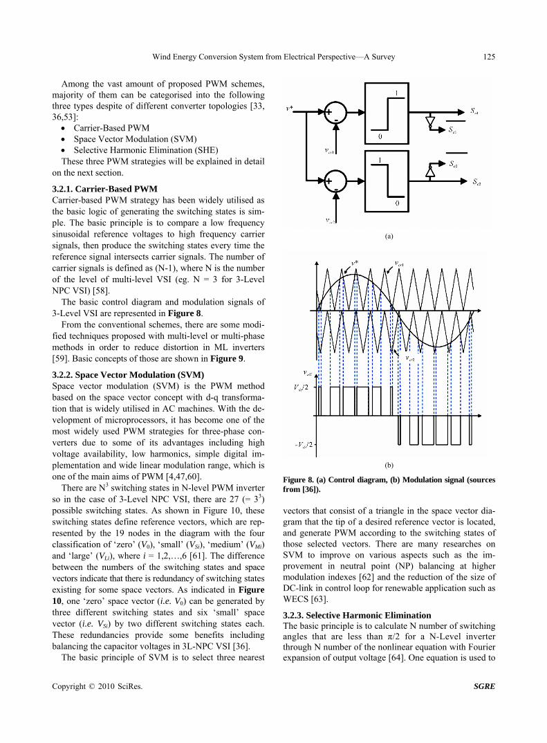
3.2.1. Carrier-Based PWM Carrier-based PWM strategy has been widely utilised as the basic logic of generating the switching states is sim-ple. The basic principle is to compare a low frequency sinusoidal reference voltages to high frequency carrier signals, then produce the switching states every time the reference signal intersects carrier signals. The number of carrier signals is defined as (N-1), where N is the number of the level of multi-level VSI (eg. N = 3 for 3-Level NPC VSI) [58].
The basic control diagram and modulation signals of 3-Level VSI are represented in Figure 8.
From the conventional schemes, there are some modi-fied techniques proposed with multi-level or multi-phase methods in order to reduce distortion in ML inverters [59]. Basic concepts of those are shown in Figure 9.
3.2.2. Space Vector Modulation (SVM) Space vector modulation (SVM) is the PWM method based on the space vector concept with d-q transforma-tion that is widely utilised in AC machines. With the de-velopment of microprocessors, it has become one of the most widely used PWM strategies for three-phase con-verters due to some of its advantages including high voltage availability, low harmonics, simple digital im-plementation and wide linear modulation range, which is one of the main aims of PWM [4,47,60].
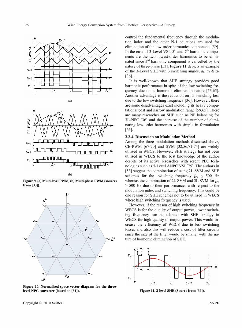
There are N3 switching states in N-level PWM inverter so in the case of 3-Level NPC VSI, there are 27 (= 33) possible switching states. As shown in Figure 10, these switching states define reference vectors, which are rep-resented by the 19 nodes in the diagram with the four classification of ‘zero’ (V0), ‘small’ (VSi), ‘medium’ (VMi) and ‘large’ (VLi), where i = 1,2,…,6 [61]. The difference between the numbers of the switching states and space vectors indicate that there is redundancy of switching states existing for some space vectors. As indicated in Figure 10, one ‘zero’ space vector (i.e. V0) can be generated by three different switching states and six ‘small’ space vector (i.e. VSi) by two different switching states each. These redundancies provide some benefits including balancing the capacitor voltages in 3L-NPC VSI [36].
The basic principle of SVM is to select three nearest
(a)
(b)
Figure 8. (a) Control diagram, (b) Modulation signal (sources from [36]). vectors that consist of a triangle in the space vector dia-gram that the tip of a desired reference vector is located, and generate PWM according to the switching states of those selected vectors. There are many researches on SVM to improve on various aspects such as the im-provement in neutral point (NP) balancing at higher modulation indexes [62] and the reduction of the size of DC-link in control loop for renewable application such as WECS [63].
3.2.3. Selective Harmonic Elimination The basic principle is to calculate N number of switching angles that are less than π/2 for a N-Level inverter through N number of the nonlinear equation with Fourier expansion of output voltage [64]. One equation is used to
Wind Energy Conversion System from Electrical Perspective—A Survey
Copyright © 2010 SciRes. SGRE
126
(a)
(b)
Figure 9. (a) Multi-level PWM, (b) Multi-phase PWM (sources from [33]).
Figure 10. Normalised space vector diagram for the three- level NPC converter (based on [61]).
control the fundamental frequency through the modula-tion index and the other N-1 equations are used for elimination of the low-order harmonics components [59]. In the case of 3-Level VSI, 5th and 7th harmonic compo-nents are the two lowest-order harmonics to be elimi-nated since 3rd harmonic component is cancelled by the nature of three-phase [53]. Figure 11 depicts an example of the 3-Level SHE with 3 switching angles, a1, a2 & a3 [36].
It is well-known that SHE strategy provides good harmonic performance in spite of the low switching fre-quency due to its harmonic elimination nature [53,65]. Another advantage is the reduction on its switching loss due to the low switching frequency [36]. However, there are some disadvantages exist including its heavy compu-tational cost and narrow modulation range [59,65]. There are many researches on SHE such as NP balancing for 3L-NPC [36] and the increase of the number of elimi-nating low-order harmonics with simple in formulation [66].
3.2.4. Discussion on Modulation Method Among the three modulation methods discussed above, CB-PWM [67-70] and SVM [32,56,71-74] are widely utilised in WECS. However, SHE strategy has not been utilised in WECS to the best knowledge of the author despite of its active researches with resent PEC tech-nologies such as 5-Level ANPC VSI [75]. The authors in [53] suggest the combination of using 2L SVM and SHE schemes for the switching frequency fsw ≤ 500 Hz whereas the combination of 2L SVM and 3L SVM for fsw > 500 Hz due to their performances with respect to the modulation index and switching frequency. This could be one reason for SHE schemes not to be utilised in WECS where high switching frequency is used.
However, if the reason of high switching frequency in WECS is for the quality of output power, lower switch-ing frequency can be adapted with SHE strategy in WECS for high quality of output power. This would in-crease the efficiency of WECS due to less switching losses and also this will reduce a cost of filter circuits since the size of the filter would be smaller with the na-ture of harmonic elimination of SHE.
Figure 11. 3-level SHE (Source from [36]).
Wind Energy Conversion System from Electrical Perspective—A Survey
Copyright © 2010 SciRes. SGRE
127
4. Issues on Grid-Connection
4.1. The Utility Grid and WECS
In the utility grid, some grid disturbances such as voltage dips often occur. In the past, grid-connected wind tur-bines needed to be disconnected from the grid when such disturbances happened in order to protect themselves from damages. However, as the penetration level of wind energy has been increasing, especially in the last decade, the role of WECS on the grid has been transforming from minor power source to main power supply stations such as coal-fired power stations along with the new grid codes. Fault Ride Through (FRT) capability under volt-age dip is one of the main focus of the new grid codes that came into effect by the German utility company, E.ON, in Germany in 2004 [4] and in other countries [76]. Another focus of the new grid code is the require-ment for wind turbines to support the power quality con-trol on the grid such as voltage/frequency stability con-trol, active/reactive power regulation, harmonics/inter- harmonics emission and flicker emission and so forth [77-79]. International Electrotechnical Commission (IEC) has also released standards on power quality for grid- connected wind turbines, which are IEC 61400-21 in 2001 and its second edition in 2008 [80].
The following section will discuss three grid-connec-tion issues that are most frequently reported and investi-gated in wind energy field, which are voltage dip, har-monic emission and flicker.
4.2. The Three Main Issues in Grid-Connected WECS
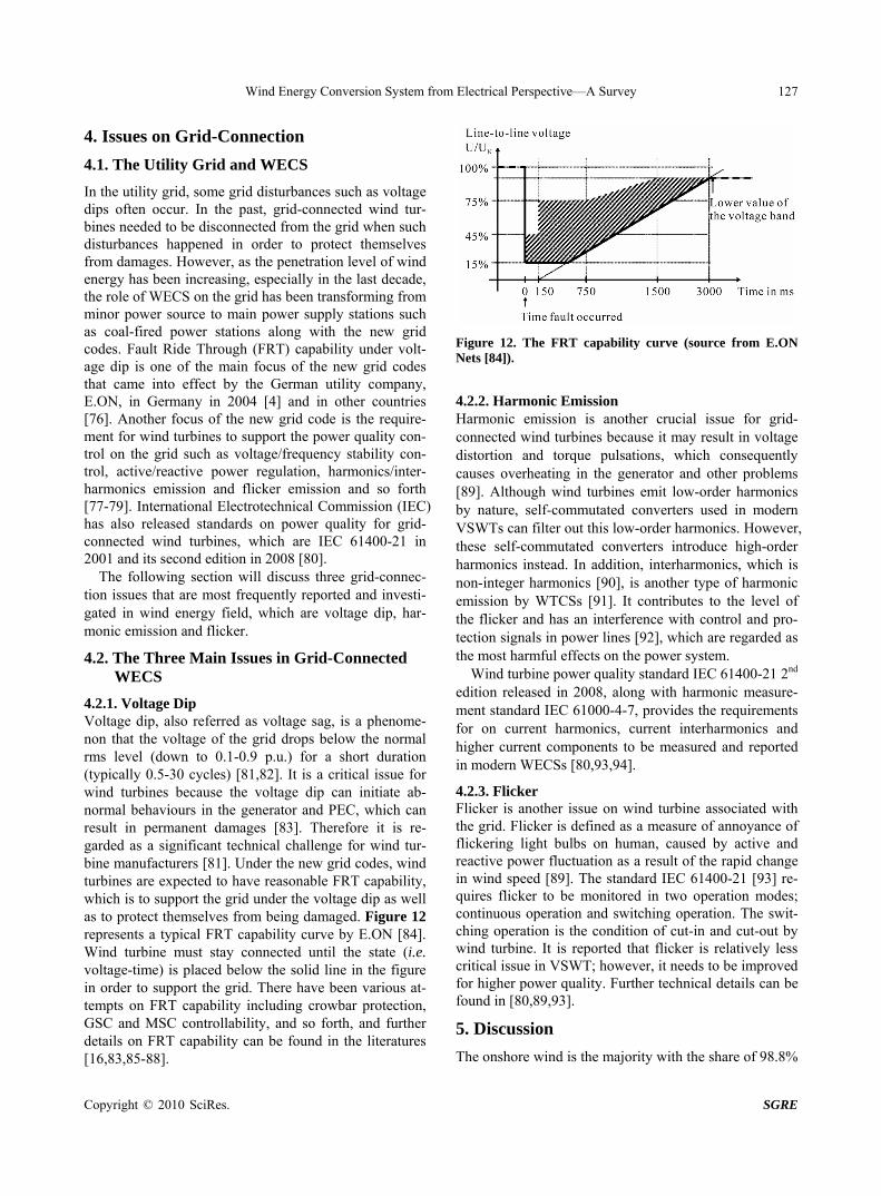
4.2.1. Voltage Dip Voltage dip, also referred as voltage sag, is a phenome-non that the voltage of the grid drops below the normal rms level (down to 0.1-0.9 p.u.) for a short duration (typically 0.5-30 cycles) [81,82]. It is a critical issue for wind turbines because the voltage dip can initiate ab-normal behaviours in the generator and PEC, which can result in permanent damages [83]. Therefore it is re-garded as a significant technical challenge for wind tur-bine manufacturers [81]. Under the new grid codes, wind turbines are expected to have reasonable FRT capability, which is to support the grid under the voltage dip as well as to protect themselves from being damaged. Figure 12 represents a typical FRT capability curve by E.ON [84]. Wind turbine must stay connected until the state (i.e. voltage-time) is placed below the solid line in the figure in order to support the grid. There have been various at-tempts on FRT capability including crowbar protection, GSC and MSC controllability, and so forth, and further details on FRT capability can be found in the literatures [16,83,85-88].
Figure 12. The FRT capability curve (source from E.ON Nets [84]).
4.2.2. Harmonic Emission Harmonic emission is another crucial issue for grid- connected wind turbines because it may result in voltage distortion and torque pulsations, which consequently causes overheating in the generator and other problems [89]. Although wind turbines emit low-order harmonics by nature, self-commutated converters used in modern VSWTs can filter out this low-order harmonics. However, these self-commutated converters introduce high-order harmonics instead. In addition, interharmonics, which is non-integer harmonics [90], is another type of harmonic emission by WTCSs [91]. It contributes to the level of the flicker and has an interference with control and pro-tection signals in power lines [92], which are regarded as the most harmful effects on the power system.
Wind turbine power quality standard IEC 61400-21 2nd edition released in 2008, along with harmonic measure-ment standard IEC 61000-4-7, provides the requirements for on current harmonics, current interharmonics and higher current components to be measured and reported in modern WECSs [80,93,94].
4.2.3. Flicker Flicker is another issue on wind turbine associated with the grid. Flicker is defined as a measure of annoyance of flickering light bulbs on human, caused by active and reactive power fluctuation as a result of the rapid change in wind speed [89]. The standard IEC 61400-21 [93] re-quires flicker to be monitored in two operation modes; continuous operation and switching operation. The swit- ching operation is the condition of cut-in and cut-out by wind turbine. It is reported that flicker is relatively less critical issue in VSWT; however, it needs to be improved for higher power quality. Further technical details can be found in [80,89,93].
5. Discussion
The onshore wind is the majority with the share of 98.8%
Wind Energy Conversion System from Electrical Perspective—A Survey
Copyright © 2010 SciRes. SGRE
128
of the current wind turbine market, in which 85% is util-ising DFIG concept [3]. However, offshore wind has been gaining more and more attention due to its rich wind resource and hence, more researches are intensively being undertaken on offshore wind. Therefore, future wind turbine market is expected to have more number of offshore wind turbines with the brushless design such as PMSG, BDFIG and especially BDFRG, due to its high reliability as discussed previously. ‘Multi-MW’ trend is also observed and BDFRG seems to have favourable characteristic for this trend among the brushless WTG designs because of its reluctance rotor. The trend also affects on the design of PECs, resulting in the preference of ML converter, especially ANPC, due to its higher voltage capability, reduced switching losses and its cost- effectiveness with IGBT modules with higher voltage rating. The increased concerns on harmonics, which is one of the discussed grid-connection issues, also make ML converter more attractive than other PEC topologies due to its lower harmonics emission. BDFRG is also re-ported to have lower harmonic emission to the grid, making this technology greatly suitable to meet the de-mand of the current and the future wind energy market [19].
6. Conclusions
This paper has reviewed the three major aspects of WECS from electrical perspective; wind turbine generators (WT Gs), power electrical converters (PECs) and grid-con-nection issues with the comparison of the six WTG types in five criteria, the discussion of the three PECs in four criteria along with three available PWM strategies and the three current market trends, ‘Variable Speed’, ‘Multi- MW’ and ‘Offshore’.
One of the key findings of this review paper is that the newer concepts, BDFIG and BDFRG have great poten-tial to come into the WECS market in the current and future wind energy market due to their attractive charac-teristics in line with the current trends of the wind energy market. Also, those newer generator concepts are re-ported to possess some benefits on grid-connection is-sues; however, there are currently few researches being undertaken. Hence, there need to be more researches on them with grid connection issues.
In terms of PECs, ANPC multilevel converter seems very attractive with the increasing wind turbine power rating and its characteristic with the grid. With PWM strategies for PECs, SVM appear to be widely utilised in WECS. It is found that SHE, which is another PWM strategy, has not appeared to be utilised in WECS despite of its benefits for power quality. Therefore, WECS with SHE seems to be another area that need to be investi-gated in the future.
REFERENCES [1] J. M. Carrasco, et al., “Power-Electronic Systems for the
Grid Integration of Renewable Energy Sources: A Sur-vey,” IEEE Transactions on Industrial Electronics, Vol. 53, No. 4, 2006, pp. 1002-1016.
[2] J. L. Sawin and E. Martinot, “Renewables 2010—Global Status Report,” REN21, 2010.
[3] WWEA, “World Wind Energy Report 2009,” WWEA (World Wind Energy Association), 2010.
[4] R. Rechsteiner, “Wind Power in Context—A Clean Revolu-tion in the Energy Sector,” 2008.
[5] F. Iov and F. Blaabjerg, “Power Electronics and Control for Wind Power Systems,” Proceedings of the IEEE Conference on Power Electronics and Machines in Wind Applications, Lincoln, 2009, pp. 1-16.
[6] M. Kazmierkowski, et al., “Control in Power Electronics: Selected Problems,” Academic Press, California, 2002.
[7] H. Polinder, et al., “Comparison of Direct-Drive and Geared Generator Concepts for Wind Turbines,” IEEE Transactions on Energy Conversion, Vol. 21, No. 3, 2006, pp. 725-733.
[8] H. Li and Z. Chen, “Overview of Different Wind Genera-tor Systems and Their Comparisons,” Renewable Power Generation, Vol. 2, No. 2, 2008, pp. 123-138.
[9] A. D. Hansen and L. H. Hansen, “Wind Turbine Concept Market Penetration over 10 Years (1995-2004),” Wind Energy, Vol. 10, No. 1, 2007, pp. 81-97.
[10] H. Polinder, et al., “Basic Operation Principles and Elec-trical Conversion Systems of Wind Turbines,” EPE Journal, Vol. 15, No. 4, 2005, pp. 43-50.
[11] T. Ackermann, “Wind Power in Power Systems,” Wiley & Sons, Ltd, Chichester, 2005.
[12] L. Hansen, et al., “Conceptual Survey of Generators and Power Electronics for Wind Turbines,” Report from Risø National Laboratory, Roskilde, Denmark, 2001.
[13] A. D. Hansen and G. Michalke, “Multi-Pole Permanent Magnet Synchronous Generator Wind Turbines’ Grid Sup-port Capability in Uninterrupted Operation during Grid Faults,” Renewable Power Generation, Vol. 3, No. 3, 2009, pp. 333-348
[14] J. Weinzettel, et al., “Life Cycle Assessment of a Floating Offshore Wind Turbine,” Renewable Energy, Vol. 34, No. 3, 2009, pp. 742-747.
[15] P. Bauer, et al., “Evaluation of Electrical Systems for Offshore Windfarms,” Industry Applications Conference, Vol. 3, 2000, pp. 1416-1423.
[16] S. Shiyi, et al., “Dynamic Analysis of the Brushless Dou-bly-Fed Induction Generator during Symmetrical Three- Phase Voltage Dips,” International Conference on Power Electronics and Drive Systems, Taipei, 2009, pp. 464-469.
[17] P. Camocardi, et al., “Autonomous BDFIG-Wind Generator with Torque and Pitch Control for Maximum Efficiency in a Water Pumping System,” International Journal of Hydrogen Energy, Vol. 35, No. 11, 2010, pp. 5778-5785.
Wind Energy Conversion System from Electrical Perspective—A Survey
Copyright © 2010 SciRes. SGRE
129
[18] E. M. Schulz and R. E. Betz, “Use of Doubly Fed Reluc-tance Machines in Wind Power Generation,” 12th Inter-national Power Electronics and Motion Control Confer-ence, Portoroz, 2006, pp. 1901-1906.
[19] M. Jovanovic, “Sensored and Sensorless Speed Control Methods for Brushless Doubly Fed Reluctance Motors,” Electric Power Applications, Vol. 3, No. 6, 2009, pp. 503 -513.
[20] R. E. Betz and M. G. Jovanovic, “Theoretical Analysis of Control Properties for the Brushless Doubly Fed Reluc-tance Machine,” IEEE Transactions on Energy Conver-sion, Vol. 17, No. 3, 2002, pp. 332-339.
[21] M. G. Jovanovic and R. E. Betz, “Power Factor Control Using Brushless Doubly Fed Reluctance Machines,” In-dustry Applications Conference, Rome, 2000, pp. 523- 530.
[22] P. H. Mellor, et al., “A Wide-Speed-Range Hybrid Vari-able-Reluctance/Permanent-Magnet Generator for Future Embedded Aircraft Generation Systems,” IEEE Transac-tions on Industry Applications, Vol. 41, No. 2, 2005, pp. 551-556.
[23] G. M. Raimondi, et al., “Aircraft Embedded Generation Systems,” International Conference on Power Electron-ics, Machines and Drives, Bath, 2002, pp. 217-222.
[24] C. Wenping, et al., “Design of a Doubly-Fed Reluctance Machine for Wind Energy Generation,” International Con-ference on Electrical Machines and Systems, Wuhan, 2008, pp. 2443-2447.
[25] R. E. Betz and M. G. Jovanovic, “The Brushless Doubly Fed Reluctance Machine and the Synchronous Reluctance Machine—A Comparison,” IEEE Transactions on Indus-try Applications, Vol. 36, No. 4, 2000, pp. 1103-1110.
[26] A. Grauers, “Design of Direct-Driven Permanent-Magnet Generators for Wind Turbines,” Ph.D. Thesis, School of Electrical and Computer Engineering, Chalmers Univer-sity of Technology, Göteborg, Sweden, 1996.
[27] M. Avis and P. Maegaard, “Worldwide Wind Turbine Market and Manufacturing Trends,” Report from XMIRE, 2008, pp. 1-23.
[28] S.-P. Breton and G. Moe, “Status, Plans and Technologies for Offshore Wind Turbines in Europe and North Amer-ica,” Renewable Energy, Vol. 34, No. 3, 2009, pp. 646- 654.
[29] G. Watson, et al., “A Framework for Offshore Wind En-ergy Development in the United States,” Report from Offshore Wind Collanorative Organising Group (MTC, U.S. Department of Energy & GE), 2005.
[30] N. Mohan, et al., “Power Electronics: Converters, Appli-cations, and Design,” John Wiley & Sons, Hoboken, 2002.
[31] L. G. González, et al., “Effects of the PWM Carrier Sig-nals Synchronization on the DC-Link Current in Back- to-Back Converters,” Applied Energy, Vol. 87, No. 8, 2010, pp. 2491-2499.
[32] R. Melício, et al., “Power Converter Topologies for Wind Energy Conversion Systems: Integrated Modeling, Con-
trol Strategy and Performance Simulation,” Renewable Energy, Vol. 35, No. 10, 2010, pp. 2165-2174.
[33] M. Malinowski, et al., “A Survey on Cascaded Multilevel Inverters,” IEEE Transactions on Industrial Electronics, Vol. 57, No. 7, 2009, pp. 2197-2206.
[34] M. Marchesoni and M. Mazzucchelli, “Multilevel Con-verters for High Power AC Drives: A Review,” IEEE In-ternational Symposium on Industrial Electronics, Buda-pest, 1993, pp. 38-43.
[35] A. Ruderman and B. Reznikov, “Three-Level H-Bridge Flying Capacitor Converter Voltage Balance Dynamics Analysis,” 13th European Conference on Power Elec-tronics and Applications, Barcelona, 2009, pp. 1-10.
[36] J. Rodriguez, et al., “A Survey on Neutral Point Clamped Inverters,” IEEE Transactions on Industrial Electronics, Vol. 57, No. 7, 2009, pp. 2219-2230.
[37] A. Nabae, et al., “A New Neutral-Point-Clamped PWM Inverter,” IEEE Transactions on Industry Applications, Vol. IA-17, 1981, pp. 518-523.
[38] M. Hiller, et al., “A New Highly Modular Medium Volt-age Converter Topology for Industrial Drive Applica-tions,” 13th European Conference on Power Electronics and Applications, Barcelona, 2009, pp. 1-10.
[39] A. Faulstich, et al., “Medium Voltage Converter for Per-manent Magnet Wind Power Generators up to 5 MW,” European Conference on Power Electronics and Applica-tions, Dresden, 2005, p. 9.
[40] L. Jun, et al., “Application of Active NPC Converter on Generator Side for MW Direct-Driven Wind Turbine,” Applied Power Electronics Conference and Exposition (APEC), Palm Springs, 2010, pp. 1010-1017.
[41] N. Celanovic and D. Boroyevich, “A Comprehensive Study of Neutral-Point Voltage Balancing Problem in Three- Level Neutral-Point-Clamped Voltage Source PWM In-verters,” IEEE Transactions on Power Electronics, Vol. 15, No. 2, 2000, pp. 242-249.
[42] T. Bruckner and S. Bemet, “Loss Balancing in Three- Level Voltage Source Inverters Applying Active NPC Switches,” Power Electronics Specialists Conference, Vancouver, 2001, pp. 1135-1140.
[43] L. Jun, et al., “Three-Level Active Neutral-Point-Clamped (ANPC) Converter with Fault Tolerant Ability,” Applied Power Electronics Conference and Exposition, Washington DC, 2009, pp. 840-845.
[44] P. Wheeler, et al., “Matrix Converters,” Power Engi-neering Journal, Vol. 16, No. 6, 2002, pp. 273-282.
[45] S. M. Barakati, et al., “Maximum Power Tracking Con-trol for a Wind Turbine System Including a Matrix Con-verter,” IEEE Transactions on Energy Conversion, Vol. 24, No. 3, 2009, pp. 705-713.
[46] D. Krug, et al., “Comparison of State-of-the-Art Voltage Source Converter Topologies for Medium Voltage Ap-plications,” Industry Applications Conference, Berlin, 2003, pp. 168-175.
[47] X. Zeng, et al., “Design and Comparison of Full-Size Converters for Large Variable-Speed Wind Turbines,”
Wind Energy Conversion System from Electrical Perspective—A Survey
Copyright © 2010 SciRes. SGRE
130
European Conference on Power Electronics and Applica-tions, Aalborg, Denmark, 2007, pp. 1-10.
[48] D. Krug, et al., “Comparison of 2.3-kV Medium-Voltage Multilevel Converters for Industrial Medium-Voltage Drives,” IEEE Transactions on Industrial Electronics, Vol. 54, No. 6, 2007, pp. 2979-2992.
[49] T. Bruckner and D. G. Holmes, “Optimal Pulse-Width Modulation for Three-Level Inverters,” IEEE Transac-tions on Power Electronics, Vol. 20, No. 1, 2005, pp. 82- 89.
[50] D. Floricau, et al., “A Comparison of Efficiency for Three-Level NPC and Active NPC Voltage Source Con-verters,” Compatibility and Power Electronics, Badajoz, 2009, pp. 331-336.
[51] R. Melício, et al., “Harmonic Assessment of Variable- Speed Wind Turbines Considering a Converter Control Malfunction,” Renewable Power Generation, Vol. 4, No. 2, 2010, pp. 139-152.
[52] P. W. Wheeler, et al., “Matrix Converters: A Technology Review,” IEEE Transactions on Industrial Electronics, Vol. 49, No. 2, 2002, pp. 276-288.
[53] J. A. Sayago, et al., “Comparison of Medium Voltage IGBT-Based 3L-ANPC-VSCs,” Power Electronics Spe-cialists Conference, Rhodes, 15-19 June 2008, pp. 851- 858.
[54] X.-M. Guo, et al., “Direct Power Control for Wind-Tur-bine Driven Doubly-Fed Induction Generator with Con-stant Switch Frequency,” International Conference on Electrical Machines and Systems, Seoul, 2007, pp. 253- 258.
[55] T. Takaku, et al., “Improved Wind Power Conversion System Using Magnetic Energy Recovery Switch (MERS),” Fourtieth IAS Annual Meeting Conference Record of the Industry Applications Conference, Vol. 3, 2005, pp. 2007 -2012.
[56] K. Won-Sang, et al., “Direct Power Control of a Doudly Fed Induction Generator with a Fixed Switching Fre-quency,” Industry Applications Society Annual Meeting, Edmonton, 2008, pp. 1-9.
[57] “Tjæreborg HVDC Light project,” ABB Power System, 2000.
[58] K. Jang-Hwan, et al., “A Carrier-Based PWM Method with Optimal Switching Sequence for a Multilevel Four- Leg Voltage-Source Inverter,” IEEE Transactions on In-dustry Applications, Vol. 44, No. 4, 2008, pp. 1239-1248.
[59] J. Rodriguez, et al., “Multilevel Inverters: A Survey of Topologies, Controls, and Applications,” IEEE Transac-tions on Industrial Electronics, Vol. 49, 2002, pp. 724- 738.
[60] Z. Keliang and W. Danwei, “Relationship between Space- Vector Modulation and Three-Phase Carrier-Based PWM: A Comprehensive Analysis [Three-Phase Inverters],” IEEE Transactions on Industrial Electronics, Vol. 49, No. 1, 2002, pp. 186-196.
[61] S. Busquets-Monge, et al., “The Nearest Three Virtual Space Vector PWM—A Modulation for the Comprehen-
sive Neutral-Point Balancing in the Three-Level NPC In-verter,” Power Electronics Letters, Vol. 2, No. 1, 2004, pp. 11-15.
[62] A. K. Gupta and A. M. Khambadkone, “A Simple Space Vector PWM Scheme to Operate a Three-Level NPC In-verter at High Modulation Index Including Overmodula-tion Region, with Neutral Point Balancing,” IEEE Trans-actions on Industry Applications, Vol. 43, No. 3, 2007, pp. 751-760.
[63] S. Busquets-Monge, et al., “Closed-Loop Control of a Three-Phase Neutral-Point-Clamped Inverter Using an Optimized Virtual-Vector-Based Pulsewidth Modulation,” IEEE Transactions on Industrial Electronics, Vol. 55, No. 5, 2008, pp. 2061-2071.
[64] J. Pontt, et al., “Mitigation of Noneliminated Harmonics of SHEPWM Three-Level Multipulse Three-Phase Active Front End Converters with Low Switching Frequency for Meeting Standard Ieee-519-92,” IEEE Transactions on Power Electronics, Vol. 19, No. 6, 2004, pp. 1594-1600.
[65] H. Bierk, et al., “Elimination of Low-Order Harmonics Using a Modified SHE-PWM Technique for Medium Voltage Induction Motor Applications,” Power & Energy Society General Meeting, Calgary, 2009, pp. 1-8.
[66] F. Wanmin, et al., “A Generalized Formulation of Quar-ter-Wave Symmetry SHE-PWM Problems for Multilevel Inverters,” IEEE Transactions on Power Electronics, Vol. 24, No. 7, 2009, pp. 1758-1766.
[67] J. L. Li, et al., “CPS-SPWM Flying Capacitor Three- Level Back-to-Back Converter Applicative Direct-Drive Wind Power Generator System,” International Confer-ence on Sustainable Power Generation and Supply, Nanjing, 2009, pp. 1-6.
[68] S. Hu, et al., “Research on a Kind of Diode-Clamped Cascade Topology in Direct-Driven Wind Power Sys-tem,” Third International Conference on Electric Utility Deregulation and Restructuring and Power Technologies, Nanjing, 2008, pp. 2509-2514.
[69] G. S. Kumar and A. Kishore, “Dynamic Analysis and Control of Output Voltage of a Wind Turbine Driven Isolated Induction Generator,” IEEE International Con-ference on Industrial Technology, Mumbai, 2006, pp. 494 -499.
[70] W. X. Lu and B. T. Ooi, “Optimal Acquisition and Ag-gregation of Offshore Wind Power by Multiterminal Volt-age-Source HVDC,” IEEE Transactions on Power Deliv-ery, Vol. 18, No. 1, 2003, pp. 201-206.
[71] X. Lie, et al., “Predictive Current Control of Doubly Fed Induction Generators,” IEEE Transactions on Industrial Electronics, Vol. 56, No. 10, 2009, pp. 4143-4153.
[72] Y. Zhenhuan and L. Hui, “Research on the Control Strat-egy of Four-Multiple Grid Connected Converter for Large -Scale Wind Energy Conversion System,” International Conference on Electrical Machines and Systems, Wuhan, 2008, pp. 2484-2488.
[73] H. Karimi-Davijani, et al., “Active and Reactive Power Control of DFIG Using SVPWM Converter,” 43rd Inter-national Universities Power Engineering Conference, Padova,
Wind Energy Conversion System from Electrical Perspective—A Survey
Copyright © 2010 SciRes. SGRE
131
2008, pp. 1-5.
[74] M. Malinowski, et al., “Control of Variable-Speed Type Wind Turbines Using Direct Power Control Space Vector Modulated 3-Level PWM Converter,” IEEE International Conference on Industrial Technology, Mumbai, 2006, pp. 1516-1521.
[75] S. R. Pulikanti and V. G. Agelidis, “Control of Neutral Point and Flying Capacitor Voltages in Five-Level She- PWM Controlled ANPC Converter,” 4th IEEE Conference on Industrial Electronics and Applications, Xi’an, 2009, pp. 172-177.
[76] M. Tsili and S. Papathanassiou, “A Review of Grid Code Technical Requirements for Wind Farms,” Renewable Power Generation, Vol. 3, No. 3, 2009, pp. 308-332.
[77] F. Iov, et al., “Mapping of Grid Faults and Grid Codes,” Risoe National Laboratory, Denmark, 2007.
[78] I. M. de Alegría, et al., “Connection Requirements for Wind Farms: A Survey on Technical Requierements and Regulation,” Renewable and Sustainable Energy Reviews, Vol. 11, No. 8, 2007, pp. 1858-1872.
[79] T. T. Sokratis and A. P. Stavros, “An Investigation of the Harmonic Emissions of Wind Turbines,” IEEE Transactions on Energy Conversion, Vol. 22, No. 1, 2007, pp. 150-158.
[80] H. Emanuel, et al., “Power Quality Measurements of Wind Energy Converters with Full-Scale Converter According to Iec 61400-21,” 10th International Conference on Elec-trical Power Quality and Utilisation, Lodz, 2009, pp. 1-7.
[81] A. Mullane, et al., “Wind-Turbine Fault Ride-Through Enhancement,” IEEE Transactions on Power Systems, Vol. 20, No. 4, 2005, pp. 1929-1937.
[82] M. Bollen, “Understanding Power Quality Problems: Voltage Sags and Interruptions,” IEEE Press, New York, 2000.
[83] J. Lopez, et al., “Dynamic Behavior of the Doubly Fed Induction Generator during Three-Phase Voltage Dips,” IEEE Transactions on Energy Conversion, Vol. 22, No. 3, 2007, pp. 709-717.
[84] “Grid Code-High and Extra High Voltage,” E.ON Netz. GmbH, Bayreuth, 2006.
[85] M. Rahimi and M. Parniani, “Grid-Fault Ride-Through Analysis and Control of Wind Turbines with Doubly Fed
Induction Generators,” Electric Power Systems Research, Vol. 80, No. 2, 2010, pp. 184-195.
[86] X.-P. Yang, et al., “Low Voltage Ride-Through of Di-rectly Driven Wind Turbine with Permanent Magnet Syn-chronous Generator,” Power and Energy Engineering Con-ference, Wuhan, 2009, pp. 1-5.
[87] S. M. Muyeen, et al., “Low Voltage Ride-Through Capa-bility Enhancement of Wind Turbine Generator System during Network Disturbance,” Renewable Power Genera-tion, Vol. 3, No. 1, 2009, pp. 65-74.
[88] P. S. Flannery and G. Venkataramanan, “Unbalanced Voltage Sag Ride-Through of a Doubly Fed Induction Generator Wind Turbine with Series Grid-Side Converter,” IEEE Transactions on Industry Applications, Vol. 45, No. 5, 2009, pp. 1879-1887.
[89] P. Sorensen, et al., “Power Quality Issues on Wind Power Installations in Denmark,” Power Engineering Society General Meeting, Tampa, 2007, pp. 1-6.
[90] “Electromagnetic Compatibility (EMC)—Part 2: Environ-ment—Section 1: Description of the Environment— Electromagnetic Environment for Low-Frequency Con-ducted Disturbances and Signalling in Public Power Sup-ply Systems,” IEC/TR61000-2-1, 1990.
[91] R. Langella, et al., “On the Assessment of Light Flicker Due to the Interharmonic Distortion Produced by Wind Turbines,” International Conference on Clean Electrical Power, Capri, 2007, pp. 529-535.
[92] Z. Hanzelka and A. Bien, “Power Quality Application Guide: Harmonics & Interharmonics,” A guide material by Leonardo Power Quality Initiative, Copper Develop-ment Association, 2004.
[93] “Wind turbines—Part 21: Measurement and Assessment of Power Quality Characteristics of Grid Connected Wind Turbines,” IEC61400-21, 2008.
[94] E. Gunther, “Harmonic and Interharmonic Measurement According to IEEE 519 and IEC 61000-4-7,” Transmission and Distribution Conference and Exhibition, Dallas, 2006, pp. 223-225.