Embed Size (px)
Citation preview

8/10/2019 WiMax-Tech for BBW Access
http://slidepdf.com/reader/full/wimax-tech-for-bbw-access 1/293
WiMAX
WiMAX: Technology for Broadband Wireless Access Loutfi Nuaymi
© 2007 John Wiley & Sons, Ltd. ISBN: 0-470-02808-4

8/10/2019 WiMax-Tech for BBW Access
http://slidepdf.com/reader/full/wimax-tech-for-bbw-access 2/293
WiMAXTECHNOLOGY FOR BROADBANDWIRELESS ACCESS
Loutfi Nuaymi
ENST Bretagne,
France

8/10/2019 WiMax-Tech for BBW Access
http://slidepdf.com/reader/full/wimax-tech-for-bbw-access 3/293
Copyright © 2007 John Wiley & Sons Ltd, The Atrium, Southern Gate, Chichester,
West Sussex PO19 8SQ, England
Telephone (44) 1243 779777
Email (for orders and customer service enquiries): [email protected]
Visit our Home Page on www.wiley.comAll Rights Reserved. No part of this publication may be reproduced, stored in a retrieval system or transmitted in
any form or by any means, electronic, mechanical, photocopying, recording, scanning or otherwise, except under
the terms of the Copyright, Designs and Patents Act 1988 or under the terms of a licence issued by the Copyright
Licensing Agency Ltd, 90 Tottenham Court Road, London W1T 4LP, UK, without the permission in writing of
the Publisher. Requests to the Publisher should be addressed to the Permissions Department, John Wiley & Sons
Ltd, The Atrium, Southern Gate, Chichester, West Sussex PO19 8SQ, England, or emailed to permreq@wiley.
co.uk, or faxed to (44) 1243 770620.
Designations used by companies to distinguish their products are often claimed as trademarks. All brand names
and product names used in this book are trade names, service marks, trademarks or registered trademarks of their
respective owners. The Publisher is not associated with any product or vendor mentioned in this book.
This publication is designed to provide accurate and authoritative information in regard to the subject mattercovered. It is sold on the understanding that the Publisher is not engaged in rendering professional services. If
professional advice or other expert assistance is required, the services of a competent professional should be sought.
Other Wiley Editorial Offices
John Wiley & Sons Inc., 111 River Street, Hoboken, NJ 07030, USA
Jossey-Bass, 989 Market Street, San Francisco, CA 94103-1741, USA
Wiley-VCH Verlag GmbH, Boschstr. 12, D-69469 Weinheim, Germany
John Wiley & Sons Australia Ltd, 42 McDougall Street, Milton, Queensland 4064, Australia
John Wiley & Sons (Asia) Pte Ltd, 2 Clementi Loop #02-01, Jin Xing Distripark, Singapore 129809
John Wiley & Sons Canada Ltd, 6045 Freemont Blvd, Mississauga, ONT, L5R 4J3Wiley also publishes its books in a variety of electronic formats. Some content that appears in print may not be
available in electronic books.
This book contains text excerpts, tables and figures reprinted with permission from IEEE Std 802.16 [IEEE
802.16-2004, IEEE Standard for Local and Metropolitan Area Networks, Air Interface for Fixed Broadband
Wireless Access Systems, Oct. 2004; IEEE 802.16f, Amendment 1: Management Information Base, Dec. 2005;
IEEE 802.16e, Amendment 2: Physical and Medium Access Control Layers for Combined Fixed and Mobile
Operation in Licensed Bands and Corrigendum 1, Feb. 2006], Copyright IEEE 2007, by IEEE. The IEEE
disclaims any responsibility or l iability resulting from the placement and use in the described manner.
British Library Cataloguing in Publication Data
A catalogue record for this book is available from the British LibraryISBN 978-0-470-02808-7 (HB)
Typeset in 10/12 pt Times Roman by Thomson Digital.
Printed and bound in Great Britain by Antony Rowe Ltd, Chippenham, England.
This book is pr inted on acid-free paper responsibly manufactured from sustainable forestry
in which at least two trees are planted for each one used for paper production.

8/10/2019 WiMax-Tech for BBW Access
http://slidepdf.com/reader/full/wimax-tech-for-bbw-access 4/293
To my wife, Gaëlle,
and our lovely daughter,
Alice
8/10/2019 WiMax-Tech for BBW Access
http://slidepdf.com/reader/full/wimax-tech-for-bbw-access 5/293
Contents
Preface and Acknowledgements xv
Abbreviations List xvii
PART ONE Global Introduction to WiMAX 1
1 Introduction to Broadband Wireless Access 3
1.1 The Need for Wireless Data Transmission 3
1.2 Wireless Networks and Broadband Wireless Access (BWA) 4
1.2.1 Different Types of Data Networks 4
1.2.2 Some IEEE 802 Data Network Standards 5
1.2.3 Cordless WLL Phone Systems 6
1.3 Applications of BWA 8
1.3.1 Wireless is Not Mobile! 10
1.3.2 Synthesis of WiMAX BWA Applications 111.4 History of BWA Technologies 11
1.4.1 Video Distribution: LMDS, MMDS and DVB 11
1.4.2 Pre-WiMAX Systems 12
2 WiMAX Genesis and Framework 13
2.1 IEEE 802.16 Standard 13
2.1.1 From 802.16-2004 to 802.16e 14
2.2 WiMAX Forum 15
2.2.1 WiMAX Forum Working Groups 15
2.2.2 WiMAX Forum White Papers 16
2.3 WiMAX Products Certification 16 2.3.1 WiMAX Certified Products 18
2.4 Predicted Products and Deployment Evolution 19
2.4.1 Product Types 19
2.4.2 Products and Deployment Timetable 19
2.5 Other 802.16 Standards 20
2.6 The Korean Cousin: WiBro 21
3 Protocol Layers and Topologies 23
3.1 The Protocol Layers of WiMAX 23
3.2 Convergence Sublayer (CS) 25
3.3 Medium Access Control Common Part Sublayer (MAC CPS) 25
3.4 Security Sublayer 25

8/10/2019 WiMax-Tech for BBW Access
http://slidepdf.com/reader/full/wimax-tech-for-bbw-access 6/293
viii Contents
3.5 PHYsical Layer 26
3.5.1 Single Carrier (SC) and OFDM 27
3.6 Network Management Reference Model 28
3.7 WiMAX Topologies 28
4 Frequency Utilisation and System Profiles 31
4.1 The Cellular Concept 31
4.1.1 Sectorisation 31
4.1.2 Cluster Size Considerations 33
4.1.3 Handover 35
4.2 Licensed and Unlicensed Frequencies 36
4.2.1 Frequency Channels and Spectral Masks 37
4.3 WiMAX Frequencies, Regulations and Availability 38
4.3.1 France 39
4.3.2 Korea 40
4.3.3 USA 40
4.3.4 UK 40
4.3.5 China 40
4.3.6 Brazil 41
4.4 WiMAX System Profiles 41
4.4.1 Fixed WiMAX System Profiles 41
4.4.2 Mobile WiMAX System Profiles 42
PART TWO WiMAX Physical Layer 43
5 Digital Modulation, OFDM and OFDMA 455.1 Digital Modulations 45
5.1.1 Binary Phase Shift Keying (BPSK) 45
5.1.2 Quadrature Phase Shift Keying (QPSK) 45
5.1.3 Quadrature Amplitude Modulation (QAM): 16-QAM and 64-QAM 47
5.1.4 Link Adaptation 47
5.2 OFDM Transmission 47
5.2.1 Basic Principle: Use the IFFT Operator 48
5.2.2 Time Domain OFDM Considerations 50
5.2.3 Frequency Domain OFDM Considerations 51
5.2.4 OFDM Symbol Parameters and Some Simple Computations 52
5.2.5 Physical Slot (PS) 53
5.2.6 Peak-to-Average Power Ratio (PAPR) 53
5.3 OFDMA and Its Variant SOFDMA 53
5.3.1 Using the OFDM Principle for Multiple Access 53
5.3.2 Scalable OFDMA (SOFDMA) 55
5.3.3 OFDMA in the OFDM PHYsical Layer: Subchannelisation 55
5.4 Subcarrier Permutations in WiMAX OFDMA PHY 57
5.4.1 The Main Permutation Modes in OFDMA 57
5.4.2 Some OFDMA PHY Definitions 57
5.4.3 PUSC Permutation Mode 58
5.4.4 FUSC Permutation Mode 65
5.4.5 AMC Permutation Mode 67
5.4.6 TUSC Permutation Mode 68
8/10/2019 WiMax-Tech for BBW Access
http://slidepdf.com/reader/full/wimax-tech-for-bbw-access 7/293
Contents ix
6 The Physical Layer of WiMAX 69
6.1 The 802.16 Physical Transmission Chains 69
6.1.1 The Global Chains 69
6.2 Channel Coding 69
6.2.1 Randomisation 706.2.2 Forward Error Correction (FEC) Codes 71
6.2.3 Interleaving 73
6.2.4 Repetition 73
6.3 Turbo Coding 74
6.3.1 Convolutional Turbo Codes (CTC) 75
6.3.2 Block Turbo Codes (BTC) 76
6.4 Transmission Convergence Sublayer (TCS) 77
6.5 Burst Profile 78
6.5.1 Downlink Burst Profile Parameters 78
6.5.2 Uplink Burst Profile Parameters 79
6.5.3 MCS Link Adaptation 79
PART THREE WiMAX Multiple Access (MAC Layer) and QoS Management 81
7 Convergence Sublayer (CS) 83
7.1 CS in 802.16 Protocol Architecture 83
7.2 Connections and Service Flow 83
7.2.1 Connection IDentifiers (CIDs) 85
7.2.2 Service Flows 85
7.3 Classification and Mapping 88
7.4 CS and QoS 90
7.5 Payload Header Suppression (PHS) 907.5.1 PHS Rules 92
7.5.2 PHS Rules Signalling 93
7.5.3 Header Compression in WiMAX 94
8 MAC Functions and MAC Frames 95
8.1 Introduction 95
8.2 MAC Addresses and MAC Frames 95
8.2.1 MAC Addresses and Other Addresses 95
8.2.2 MAC Frames 96
8.2.3 MAC Header Format 96
8.2.4 MAC Subheaders and Special Payloads 100
8.3 Fragmentation, Packing and Concatenation 100
8.3.1 Fragmentation 100
8.3.2 Packing 101
8.3.3 Concatenation 102
8.4 Basic, Primary and Secondary Management Connections 102
8.5 User Data and MAC Management Messages 105
8.6 TLV Encoding in the 802.16 Standard 105
8.6.1 TLV Encoding Sets 106
8.7 Automatic Repeat Request (ARQ) 106
8.7.1 ARQ Feedback Format 108
8.7.2 Hybrid Automatic Repeat Request (HARQ) Mechanism 109
8.8 Scheduling and Link Adaptation 110

8/10/2019 WiMax-Tech for BBW Access
http://slidepdf.com/reader/full/wimax-tech-for-bbw-access 8/293
x Contents
9 Multiple Access and Burst Profile Description 113
9.1 Introduction 113
9.2 Duplexing: Both FDD and TDD are Possible 113
9.2.1 FDD Mode 114
9.2.2 TDD Mode 1149.3 Transmission of Downlink and Uplink Subframes 115
9.3.1 OFDM PHY Downlink Subframe 116
9.3.2 OFDM PHY Uplink Subframe 117
9.3.3 OFDMA PHY Frame 118
9.3.4 Frame Duration 119
9.3.5 Preambles 120
9.4 Maps of Multiple Access: DL-MAP and UL-MAP 121
9.4.1 DL-MAP Message 122
9.4.2 UL-MAP Message 123
9.4.3 OFDMA PHY UL-MAP and DL-MAP Messages 124
9.5 Burst Profile Usage: DCD Message and the DIUC Indicator 1259.5.1 Burst Profile Selection Thresholds 125
9.5.2 DCD (Downlink Channel Descriptor) Message 126
9.5.3 Transmission of the DCD Message 128
9.5.4 An Example of the DCD Message 128
9.5.5 DIUC Values 129
9.5.6 UCD (Uplink Channel Descriptor) Message and UIUC Indicator 132
9.6 Mesh Frame 134
9.6.1 Network Control Subframe 134
9.6.2 Schedule Control Subframe 135
10 Uplink Bandwidth Allocation and Request Mechanisms 13710.1 Downlink and Uplink Allocation of Bandwidth 137
10.2 Types of Uplink Access Grant-request 138
10.2.1 Incremental and Aggregate Bandwidth Request 138
10.2.2 Standalone and Piggyback Bandwidth Request 138
10.3 Uplink Access Grant-request Mechanisms 140
10.3.1 Unsolicited Bandwidth Grants 141
10.3.2 Unicast Polling 141
10.3.3 Contention-based Group (Multicast or Broadcast) Polling 142
10.3.4 Management of Multicast Polling Groups 143
10.3.5 Contention Resolution for Group Polling 144
10.3.6 Bandwidth Stealing 146
10.3.7 Example of Uplink Access 147
10.4 Contention-based Focused Bandwidth Request in OFDM PHY 150
10.4.1 Full Contention (REQ Region Full) 151
10.4.2 Focused Contention (REQ Region Focused) 151
10.4.3 Summary of Contention-based Uplink Grant-request Methods 153
10.5 Contention-based CDMA Bandwidth Request in OFDMA PHY 153
11 Network Entry and Quality of Service (QoS) Management 155
11.1 Ranging 155
11.1.1 Ranging Messages 155
11.1.2 Initial Ranging 158
11.1.3 Ranging (or Periodic Ranging) 160
8/10/2019 WiMax-Tech for BBW Access
http://slidepdf.com/reader/full/wimax-tech-for-bbw-access 9/293
Contents xi
11.2 Link Adaptation 161
11.2.1 Downlink Channel Link Adaptation 162
11.2.2 Uplink Channel Link Adaptation 163
11.3 The Five Scheduling Services or QoS Classes 163
11.3.1 Unsolicited Grant Service (UGS) 16511.3.2 Extended Real-Time Polling Service (ertPS) 166
11.3.3 Real-Time Polling Service (rtPS) 166
11.3.4 Non-Real-Time Polling Service (nrtPS) 166
11.3.5 Best Effort (BE) 167
11.4 Scheduling and Deployment of Services Over WiMAX 167
11.4.1 The Scheduler is in the BS! 167
11.4.2 Scheduling of the Different Transmission Services 168
11.5 Dynamic Service Addition and Change 170
11.5.1 Service Flow Provisioning and Activation 170
11.5.2 Service Flow Creation 171
11.5.3 Service Flow Modification and Deletion 17311.5.4 Authorisation Module 174
11.6 Network Entry 175
11.6.1 Registration 179
11.6.2 De-registration and Re-registration 180
11.6.3 SS Reset 181
PART FOUR Diverse Topics 183
12 Efficient Use of Radio Resources 185
With the contribution of Jérôme Brouet, Alcatel, France
12.1 Introduction 18512.2 Radio Engineering Consideration for WiMAX Systems 186
12.2.1 LOS/NLOS Propagation 186
12.2.2 Radio Parameters and System Gains 186
12.2.3 WiMAX Radio Features that Enhance the Range 187
12.2.4 Frequency Planning Guidelines 188
12.2.5 Base Station Synchronisation 188
12.3 Radio Resource Management Procedures 189
12.3.1 Power Control 189
12.3.2 Dynamic Frequency Selection (DFS) 190
12.3.3 Other Radio Resource Management Procedures 192
12.3.4 Channel Measurements 192
12.3.5 Support of Radio Resource Management in the WiMAX RAN 194
12.4 Advanced Antenna Technologies in WiMAX 194
12.4.1 Beamforming or AAS Technologies 195
12.4.2 MIMO (Multiple-Input Multiple-Output) Solution 200
12.4.3 About the Implementation of Advanced Antenna Technologies 203
12.5 Multicast Broadcast Services (MBS) 204
12.5.1 Multi-BS Access MBS 204
12.5.2 MBS Frame 205
13 WiMAX Architecture 207
With the contribution of Jérôme Brouet, Alcatel, France
13.1 The Need for a Standardised WiMAX Architecture 207
8/10/2019 WiMax-Tech for BBW Access
http://slidepdf.com/reader/full/wimax-tech-for-bbw-access 10/293
xii Contents
13.1.1 Supporting Working Groups and Documents 207
13.1.2 High-level Architecture Requirements 208
13.2 Network Reference Model 209
13.2.1 Overview and Definitions 209
13.2.2 ASN Reference Model and Profiles 21013.2.3 CSN Reference Model 213
13.2.4 Reference Points 214
13.3 Network Functionalities 215
13.3.1 Network Discovery and Selection 215
13.3.2 IP Addressing 216
13.3.3 AAA Framework 216
13.3.4 Mobility 217
13.3.5 End-to-End Quality of Service 217
14 Mobility, Handover and Power-Save Modes 219
14.1 Handover Considerations 21914.2 Network Topology Acquisition 220
14.2.1 Network Topology Advertisement 220
14.2.2 MS Scanning of Neighbour BSs 220
14.2.3 Association Procedure 221
14.2.4 CDMA Handover Ranging and Automatic Adjustment 222
14.3 The Handover Process 222
14.3.1 Cell Reselection 222
14.3.2 Handover Decision and Initiation 223
14.3.3 Synchronisation to a Target BS Downlink 223
14.3.4 Ranging and Network Re-entry 224
14.3.5 Termination of MS Context 22414.3.6 Handover Cancellation 224
14.4 Fast BS Switching (FBSS) and Macro Diversity Handover (MDHO) 225
14.4.1 Diversity Set 225
14.4.2 Different Types of BS for a Given MS 225
14.4.3 FBSS (Fast BS Switching) 226
14.4.4 MDHO (Macro Diversity Handover) 226
14.5 Power-Save Modes 227
14.5.1 Sleep Mode 227
14.5.2 Idle Mode 228
15 Security 231
15.1 Security Elements Used in the 802.16 Standard 231
15.1.1 Encryption Algorithms 232
15.1.2 X.509 Certificate 232
15.1.3 Encryption Keys and Security Associations (SAs) 233
15.2 Authentication and the PKM Protocol 235
15.2.1 PKM Protocol MAC Management Messages 235
15.2.2 PKMv1: the BS Authenticates the SS and then Provides it with Keying Material 236
15.2.3 Mutual Authentication as Defined in 802.16e 239
15.2.4 Authorisation Key (AK) Management 240
15.2.5 Management of the Authorisation Key in PKMv2 242
15.3 Data Encryption 242
15.3.1 Generation of Encryption Keys 243
8/10/2019 WiMax-Tech for BBW Access
http://slidepdf.com/reader/full/wimax-tech-for-bbw-access 11/293
Contents xiii
15.3.2 Generation of Encryption Keys in the 802.16e Amendment 245
15.3.3 Traffic Encryption Keys and Handover 246
15.3.4 Traffic Encryption Algorithms 246
15.3.5 Traffic Encryption Algorithms Added in the 802.16e Amendment 248
15.4 Message Authentication with HMAC 24815.4.1 Message Authentication Keys 249
15.5 Other Security Issues 250
16 Comparisons and Conclusion 251
16.1 Comparison Between Fixed WiMAX and Mobile WiMAX 251
16.2 Comparison Between WiMAX and WiFi 252
16.3 Comparison Between WiMAX and 3G 253
16.3.1 Advantages of the 3G Cellular System 253
16.3.2 Advantages of the (Mobile) WiMAX System 254
16.4 Final Thoughts and Conclusion 254
Annex A: The Different Sets of MAC Management Messages 255
Annex B: Example of a Downlink Channel Descriptor (DCD) Message 265
References 273
Index 277

8/10/2019 WiMax-Tech for BBW Access
http://slidepdf.com/reader/full/wimax-tech-for-bbw-access 12/293
Preface and Acknowledgements
WiMAX technology is presently one of the most promising global telecommunication sys-
tems. Great hopes and important investments have been made for WiMAX, which is a Broad-
band Wireless Access System having many applications: fixed or last-mile wireless access,
backhauling, mobile cellular network, telemetering, etc. WiMAX is based on the IEEE 802.16standard, having a rich set of features. This standard defines the Medium Access Layer and
the Physical Layer of a fixed and mobile Broadband Wireless Access System. WiMAX is also
based on the WiMAX Forum documents.
This book is intended to be a complete introduction to the WiMAX System without having
the ambition to replace thousands of pages of documents of the IEEE 802.16 standard and
amendments and WiMAX Forum documents. There will always be a need to refer to these
for any technical development of a specific aspect of WiMAX.
Besides my teaching of other wireless systems (GSM/GPRS, UMTS and WiFi) and re-
lated research, I had the occasion to write a first presentation about WiMAX technology, by
coincidence, in 2003 and then a WiMAX report. Student projects, PhD work and wirelessnetwork courses teaching then provided me with the building blocks for a first WiMAX docu-
ment. Starting from February 2006, providing ENST Bretagne Inter-Enterprise training and
WiMAX training for other specific companies allowed me to develop an even more complete
presentation of WiMAX, using text and slides. I thought it might be helpful for colleague
engineers, IT managers and undergraduate and graduate students to use this document as a
clear and complete introduction to WiMAX technology. WiMAX users can then, if needed,
access more easily some specific part of the standard for a specific development.
Some repetitions will be found in this book. This has been done on purpose in order to
provide a complete description of the different aspects of this powerful but also sometimes
complex technology.The book can be divided globally into four independent parts. Part I, Chapters 1 to 4, is a
global introduction to WiMAX. Part II, Chapters 5 and 6, describes the physical layer with
a focus on the main features of the WiMAX physical layer, OFDM transmission and its
OFDMA variant. Part III, Chapters 7 to 11, describes the MAC layer and, more specifically,
the multiple access and the QoS Management of WiMAX. Part IV, Chapters 12 to 16, covers
diverse topics: radio resource management, the network architecture, mobility and security.
The book ends with some comparisons and a conclusion.
Without doubt, this book about such a recent technology could not have been published
so early without precious help. I wish to thank Jérôme Brouet, from Alcatel, who agreed to
write large parts of Chapters 12 and 13. His excellent knowledge of WiMAX has always been
a great help to me. I thank trainee student Gérard Assaf for the very good work he provided

8/10/2019 WiMax-Tech for BBW Access
http://slidepdf.com/reader/full/wimax-tech-for-bbw-access 13/293
xvi Preface and Acknowledgements
for figures, synthesis notes and bibliography notes. I also thank trainee students and ENST
Bretagne students Aymen Belghith, Maël Boutin, Matthieu Jubin, Ziad Noun and Badih Sou-
haid for the same type of help. Other student reports and projects were also useful.
I am grateful for the discussions and comments of (the list is not exhaustive) Olfa Ben
Haddada, Luc Brignol, Nora Cuppens, Guillaume Lebrun, Bertrand Léonard and BrunoTharon and my colleagues Xavier Lagrange, Laurence Rouillé and Philippe Godlewski. The
wide knowledge of Francis Dupont about Internet and network security (and, by the way, a
lot of other topics) helped me with the security chapter. Walid Hachem provided precious
help. My colleague Xavier Lagrange provided total support for this book project.
I also wish to thank Prakash Iyer and Bruce Holloway from the WiMAX Forum for pre-
cious remarks and authorisations.
I acknowledge the reason for the existence of this book, the IEEE 802.16-2004 standard
and its amendment 802.16e and WiMAX Forum Documents. I wish to thank the authors of
these documents.
Sarah Hinton, my Project Editor at John Wiley & Sons, Ltd was extremely patient with me.In addition, she helped me a lot with this project.
I thank my parents-in-law Michelle and Marcel for their total support during the marathon
last sprint when I invaded Marcel’s office for three complete weeks, day and night. My mother
Neema also had her share of this book effort.
I end these acknowledgements with the most important: I thank Gaëlle for her support
throughout the long writing times. Our little wonder Alice provided me with some of the
charming energy she spent for her first steps while I was finishing the book.
I did my best to produce an error-free book and to mention the source of every piece of
information. I welcome any comment or suggestion for improvements or changes that could
be implemented in possible future editions of this book. The email address for gathering
feedback is [email protected].

8/10/2019 WiMax-Tech for BBW Access
http://slidepdf.com/reader/full/wimax-tech-for-bbw-access 14/293
Abbreviations List
This list contains the main abbreviations used throughout this book. First the general list is
given and then the QoS Classes, the MAC management messages and the security abbrevia-
tions list.
3G Third-generation cellular system. Examples: UMTS and cdma2000
AAA Authentication Authorisation and Accounting. Protocol realising these three
functions. Often related to an AAA server
AAS Adaptive Antenna Systems. The WiMAX MAC Layer has functionalities that
allow the use of AAS
ACK ACKnowledge or ACKnowledgement. Control message used in the ARQ
mechanism
AMC Adaptive Modulation and Coding
ARCEP (French telecommunications regulation authority) Autorité de Régulation des
Communications Electroniques et des Postes. Old name: ART (Autorité deRégulation des Télécommunications)
ARQ Automatic Repeat reQuest. Layer two transmission protocol
ASN Access Service Network. The WiMAX radio access network, mainly
composed of BSs and ASN-GW
ASN-GW ASN Gateway. ASN equipment, between BSs and CSN
ASP Application Service Provider. Business entity that provides applications or
services via (Visited) V-NSP or (Home) H-NSP
ATM Asynchronous Transfer Mode
BE Best Effort. BE is one of the five QoS classes of WiMAX. Used for lowest
priority time-constraint services such as emailBER Bit Error Rate
BF Beamforming. Adaptive Antenna Systems technology
BPSK Binary Phase Shift Keying. Binary digital modulation
BR Bandwidth Request
BS Base Station
BSID Base Station IDentifier
BSN Block Sequence Number. Used in Selective ACK variant of the ARQ mechanism
BTC Block Turbo Code. Turbo coding variant
BW Bandwidth
BWA Broadband Wireless Access. High data rate radio access. WiMAX is a BWA
CALEA Communications Assistance Law Enforcement Act
CBR Constant Bit Rate. Data transmission service type (e.g. non-optimised voice)
8/10/2019 WiMax-Tech for BBW Access
http://slidepdf.com/reader/full/wimax-tech-for-bbw-access 15/293
8/10/2019 WiMax-Tech for BBW Access
http://slidepdf.com/reader/full/wimax-tech-for-bbw-access 16/293
8/10/2019 WiMax-Tech for BBW Access
http://slidepdf.com/reader/full/wimax-tech-for-bbw-access 17/293
xx Abbreviations List
MAN Metropolitan Area Network. IEEE 802.16 is a Wireless MAN system
MBS Multicast and Broadcast Services feature
MCS Modulation and Coding Scheme
MDHO Macro Diversity HandOver. A state where the mobile communicates with
more than one BSMIB Management Information Base. The BS and SS managed nodes collect and
store the managed objects in an 802.16 MIB format
MIMO Multiple-Input Multiple-Output
MIP Mobile IP
MMDS Multichannel Multipoint Distribution Service
MPDU MAC PDU
MS Mobile Station
MSDU MAC SDU
NACK Non-ACKnowledge or Non-ACKnowledgement. Control message used in the
ARQ mechanismNAP Network Access Provider (cf. Architecture WiMAX). Business entity that
provides a WiMAX radio access infrastructure to one or more WiMAX
Network Services
NLoS Non-Line-of-Sight. A radio transmission is NLoS if it do not fulfil certain
conditions (Fresnel zone sufficiently clear)
nrtPS Non-real-time Polling Services. One of the five QoS classes of WiMAX
NSP Network Service Provider (cf. Architecture WiMAX). Business entity that
provides IP connectivity and WiMAX services to WiMAX subscribers
NWG NetWork Group. WiMAX Forum Group. In charge of creating the high-level
architecture specifications
OEM Original Equipment Manufacturer
OFDM Orthogonal Frequency Division Multiplexing. Transmission technique.
The principle is to transmit the information on many orthogonal frequency
subcarriers
OFDMA Orthogonal Frequency Division Multiple Access. OFDM used as a multiple
access scheme
OPUSC Optional PUSC
PAPR Peak-to-Average Power Ratio. In an OFDM transmission, the PAPR is the
peak value of transmitted subcarriers to the average transmitted signal
PBR PiggyBack Request. Grant Management subheader field indicating the uplink
bandwidth requested by the SS
PCM Pulse Coded Modulation. Classical phone signal transmission system.
Variants are T1 and E1
PDU Protocol Data Unit
PHS Payload Header Suppression. Optional CS sublayer process
PHSF Payload Header Suppression Field
PHSI Payload Header Suppression Index
PHSM Payload Header Suppression Mask
PHSS Payload Header Suppression Size
PHSV Payload Header Suppression Valid
PHY PHYsical layer
8/10/2019 WiMax-Tech for BBW Access
http://slidepdf.com/reader/full/wimax-tech-for-bbw-access 18/293
Abbreviations List xxi
PICS Protocol Implementation Conformance Specification document. In the
conformance test, the BS/SS units must pass all mandatory and prohibited
test conditions called out by the test plan for a specific system profile.
PM Poll-Me bit. SSs with currently active UGS connections may set the PM bit (in
the Grant Management subheader) in a MAC packet of the UGS connectionto indicate to the BS that they need to be polled to request bandwidth for non-
UGS connections
PMP Point-to-MultiPoint. Basic WiMAX topology
PN Pseudo-Noise sequence
PRBS Pseudo-Random Binary Sequence. Used in the randomisation block
PS Physical Slot. Function of the PHYsical Layer. Used as a resource attribution
unit
PUSC Partial Usage of SubChannels. OFDMA Permutation mode
QAM Quadrature Amplitude Modulation
QoS Quality of ServiceQPSK Quadrature Phase Shift Keying
RF Radio Frequency
RFC Request For Comment. IETF document
RRA Radio Resource Agent
RRC Radio Resource Controller
RRM Radio Resource Management
RS Reed–Solomon code. Channel coding
RSSI Received Signal Strength Indicator. Indicator of the signal-received power
level
RTG Receive/transmit Transition Gap. The RTG is a gap between the uplink burst
and the subsequent downlink burst in a TDD transceiver
RTP Real-Time Protocol
rtPS Real-time Polling Services. One of the five QoS classes of WiMAX
SAP Service Access Point
SBC SS Basic Capability. The BS and the SS agree on the SBC at SS network entry
SC Single Carrier. A single carrier transmission is a transmission where no
OFDM is applied
SDU Service Data Unit
SFA Service Flow Authorisation
SFID Service Flow IDentifier. An MAC service flow is identified by a 32-bit SFID
SFM Service Flow Management
SI Slip Indicator. Grant Management subheader field. Indicates slip of uplink
grants relative to the uplink queue depth
SISO Single-Input Single-Output. Specific case of MIMO
SLA Service Level Agreements
SM Spatial Multiplexing. MIMO family of algorithms
SN Sequence Number. Transmitted block number used in the ARQ mechanism
SNMP Simple Network Management Protocol. IETF Network Management
Reference model protocol
SNR Signal-to-Noise Ratio. The noise includes interferer signals. Also known as
CINR (Carrier-to-Interference-and-Noise Ratio)
8/10/2019 WiMax-Tech for BBW Access
http://slidepdf.com/reader/full/wimax-tech-for-bbw-access 19/293
xxii Abbreviations List
SOFDMA Scalable OFDMA
SPID SubPacket IDentifier. Used in the HARQ process
SS Subscriber Station
STBC Space Time Block Coding. MIMO variant
STC Space Time Coding. MIMO variantTCP Transmission Control Protocol
TCS Transmission Convergence Sublayer. Optional PHY mechanism
TDD Time Division Duplexing
TDM Time Division Multiplexing. A TDM burst is a contiguous portion of a TDM
data stream using the same PHY parameters. These parameters remain
constant for the duration of the burst. TDM bursts are not separated by gaps
or preambles
TFTP Trivial File Transfer Protocol
TLV Type/Length/Value
TO Transmission OpportunityTTG Tx/Rx Transition Gap. Time gap between the downlink burst and the
subsequent uplink burst in the TDD mode
TUSC Tile Usage of SubChannels. OFDMA Permutation mode. Two variants:
TUSC1 and TUSC2
UDP User Datagram Protocol
UDR Usage Data Records
UCD Uplink Channel Descriptor. Uplink Descriptor MAC Management message
UGS Unsolicited Grant Services. One of the five QoS classes of WiMAX
UIUC Uplink Interval Usage Code. Burst profile identifier, accompanying each
uplink burst
UL UpLink
UL-MAP UpLink MAP. The MAC Management message indicating the contents of an
uplink frame
UTC Universal Coordinated Time
V-NSP Visited NSP
VoIP Voice over IP
WiFi Wireless Fidelity. IEEE 802.11 certification consortium
WiMAX Worldwide Interoperability for Microwave Access Forum. The WiMAX
Forum provides certification of conformity, compatibility and interoperability
of IEEE 802.16 products. In extension WiMAX is also the common name for
the technology mainly based on IEEE 802.16
WLL Wireless Local Loop. Cordless phone system
IEEE 802.16 Qos Classes (or Service Classes)
BE Best Effort. Used for lowest priority time-constraint services such as email
ertPS Extended real-time Polling Service. New QoS class defined in the 802.16e
amendment. Intermediary between rtPS and UGS
nrtPS Non-real-time Polling Services. Used for non-real-time services having some time
constraints
8/10/2019 WiMax-Tech for BBW Access
http://slidepdf.com/reader/full/wimax-tech-for-bbw-access 20/293
Abbreviations List xxiii
rtPS Real-time Polling Services. Used for variable data rate real-time services.
Example is the MPEG video
UGS Unsolicited Grant Services. Dedicated to Constant Bit Rate (CBR) services, UGS
guarantees fixed-size data packets issued at periodic intervals. Example of use is
T1/E1 transmissions
IEEE 802.16 MAC Management Messages
Note that more details of the MAC Management messages can be found in Annex A.
AAS-BEAM_REQ AAS Beam REQuest message
AAS-BEAM_RSP AAS Beam ReSPonse message
AAS-Beam_Select AAS Beam Select message
AAS-FBCK-REQ AAS FeedBaCK REQuest message
AAS-FBCK-RSP AAS FeedBaCK ReSPonse message
ARQ-Discard ARQ Discard message
ARQ-Feedback Standalone ARQ Feedback message
ARQ- Reset ARQ Reset message
CLK-CMP SS network CLocK CoMParison message
DBPC-REQ Downlink Burst Profile Change REQuest message
DBPC-RSP Downlink Burst Profile Change ReSPonse message
DCD Downlink Channel Descriptor message
DL-MAP DownLink Access Definition message
DREG-CMD De/re-REGister CoMmanD message
DREG-REQ SS De-REGistration message
DSA-ACK Dynamic Service Addition ACKnowledge message
DSA-REQ Dynamic Service Addition REQuest message
DSA-RSP Dynamic Service Addition ReSPonse message
DSC-ACK Dynamic Service Addition ACKnowledge message
DSC-REQ Dynamic Service Change REQuest message
DSC-RSP Dynamic Service Change ReSPonse message
DSD-REQ Dynamic Service Deletion REQuest message
DSD-RSP Dynamic Service Deletion ReSPonse message
DSX-RVD DSx ReceiVeD message
FPC Fast Power Control message
MBS_MAP MBS MAP message
MCA-REQ MultiCast Assignment REQuest message
MCA-RSP MultiCast Assignment ReSPonse message
MSH-CSCF MeSH Centralised Schedule ConFiguration message
MSH-CSCH MeSH Centralised SCHedule message
MSH-DSCH MeSH Distributed SCHedule message
MSH-NCFG MeSH Network ConFiGuration message
MSH-NENT MeSH Network ENTry message
MOB_ASC-REP ASsoCiation result REPort message
MOB_BSHO-REQ BS HO REQuest message
8/10/2019 WiMax-Tech for BBW Access
http://slidepdf.com/reader/full/wimax-tech-for-bbw-access 21/293
xxiv Abbreviations List
MOB_BSHO-RSP BS HO ReSPonse message
MOB_HO-IND HO INDication message
MOB_MSHO-REQ MS HO REQuest message
MOB_NBR-ADV NeighBouR ADVertisement message
MOB_PAG-ADV BS broadcast PAGing Advertisement messageMOB_SCN-REQ SCaNning interval allocation REQuest message
MOB_SCN-RSP SCaNning interval allocation ReSPonse message
MOB_SCN-REP SCaNning result REPort message
MOB_SLP-REQ SLeeP REQuest message
MOB_SLP-RSP SLeeP ReSPonse message
MOB_TRF-IND TRaFfic INDication message
PKM-REQ Privacy Key Management REQuest message
PKM-RSP Privacy Key Management ReSPonse message
PMC_REQ Power control Mode Change REQuest message
PMC_RSP Power control Mode Change ReSPonse messagePRC-LT-CTRL Setup/tear-down of Long-Term MIMO precoding message
REG-REQ REGistration REQuest message
REG-RSP REGistration ReSPonse message
REP-REQ Channel measurement REPort REQuest message
REP-RSP Channel measurement REPort ReSPonse message
RES-CMD RESet CoMmanD message
RNG-REQ RaNGing REQuest message
RNG-RSP RaNGing ReSPonse message
SBC-REQ SS Basic Capability REQuest message
SBC-RSP SS Basic Capability ReSPonse message
TFTP-CPLT Config File TFTP ComPLeTe Message
TFTP-RSP Config File TFTP complete ReSPonse message
UCD Uplink Channel Descriptor message
UL-MAP UpLink Access Definition message
Security Abbreviations
AES Advanced Encryption Standard. The AES Algorithm is a shared
(secret)-key encryption algorithm
AK Authorisation Key (PKMv1 and PKMv2)
CA Certification Authority
CBC Cipher Block Chaining mode. An AES mode
CCM Counter with CBC-MAC (CBC: Cipher Block Chaining mode). AES
CCM is an authenticate-and-encrypt block cipher mode used in IEEE
802.16 for data encryption
CMAC Cipher-based Message Authentication Code
CMAC_KEY_D CMAC KEY for the Downlink. Used for authenticating messages in
the downlink direction
CMAC_KEY_U CMAC KEY for the Uplink. Used for authenticating messages in the
uplink direction
DES Data Encryption Standard. Shared (secret)-key encryption algorithm

8/10/2019 WiMax-Tech for BBW Access
http://slidepdf.com/reader/full/wimax-tech-for-bbw-access 22/293
Abbreviations List xxv
EAP Extensible Authentication Protocol. Mutual authentification protocol
framework
EIK EAP Integrity Key
GKEK Group Key Encryption Key (PKMv2)
GTEK Group Traffic Encryption Key (PKMv2)HMAC Hashed Message Authentication Code
HMAC_KEY_D HMAC Key for the Downlink. Used for authenticating messages in the
downlink direction
HMAC_KEY_S HMAC Key in the Mesh mode
HMAC_KEY_U HMAC Key for the Uplink. Used for authenticating messages in the
uplink direction
KEK Key Encryption Key (PKMv1 and PKMv2)
MAK MBS Authorisation Key (PKMv2)
MGTEK MBS Group Traffic Encryption Key (PKMv2)
MTK MBS Traffic Key (PKMv2)PAK Primary Authorisation Key (PKMv2)
PKM Privacy Key Management protocol
PMK Pairwise Master Key (PKMv2)
PN Packet Number
RSA Rivest Shamir Adleman. Public key encryption algorithm used to
encrypt some MAC management security messages, using the SS
public key
SA Security Association. Set of security information agreed between a BS
and one or more of its client SSs (methods for data encryption, data
authentication, keys exchange, etc.)
SAID Security Association IDentifier. A 16-bit identifier shared between the
BS and the SS that uniquely identifies a security association
SHA Secure Hash algorithm
TEK Traffic Encryption Key (PKMv1 and PKMv2)

8/10/2019 WiMax-Tech for BBW Access
http://slidepdf.com/reader/full/wimax-tech-for-bbw-access 23/293
Part OneGlobal Introduction
to WiMAX
WiMAX: Technology for Broadband Wireless Access Loutfi Nuaymi
© 2007 John Wiley & Sons, Ltd. ISBN: 0-470-02808-4

8/10/2019 WiMax-Tech for BBW Access
http://slidepdf.com/reader/full/wimax-tech-for-bbw-access 24/293
1Introduction to BroadbandWireless Access
1.1 The Need for Wireless Data Transmission
Since the final decades of the twentieth century, data networks have known steadily growing
success. After the installation of fixed Internet networks in many places all over the planet
and their now large expansion, the need is now becoming more important for wireless access.
There is no doubt that by the end of the first decade of the twentieth century, high-speed wire-
less data access, i.e. in Mb/s, will be largely deployed worldwide.
Wireless communication dates back to the end of the nineteenth century when the Maxwell
equations showed that the transmission of information could be achieved without the need for a
wire. A few years later, experimentations such as those of Marconi proved that wireless transmis-
sion may be a reality and for rather long distances. Through the twentieth century, great electronic
and propagation discoveries and inventions gave way to many wireless transmission systems.
In the 1970s, the Bell Labs proposed the cellular concept, a magic idea that allowed the cov-
erage of a zone as large as needed using a fixed frequency bandwidth. Since then, many wire-
less technologies had large utilisation, the most successful until now being GSM, the Global
System for Mobile communication (previously Groupe Spécial Mobile), originally European
second generation cellular system. GSM is a technology mainly used for voice transmission in
addition to low-speed data transmission such as the Short Message Service (SMS).
The GSM has evolutions that are already used in many countries. These evolutions are
destined to facilitate relatively high-speed data communication in GSM-based networks. The
most important evolutions are:
• GPRS (General Packet Radio Service), the packet-switched evolution of GSM;
• EDGE (Enhanced Data rates for GSM Evolution), which includes link or digital modula-
tion efficiency adaptation, i.e. adaptation of transmission properties to the (quickly varying)
radio channel state.
In addition to GSM, third-generation (3G) cellular systems, originally European and Japanese
UMTS (Universal Mobile Telecommunication System) technology and originally American
cdma2000 technology, are already deployed and are promising wireless communication systems.
WiMAX: Technology for Broadband Wireless Access Loutfi Nuaymi
© 2007 John Wiley & Sons, Ltd. ISBN: 0-470-02808-4

8/10/2019 WiMax-Tech for BBW Access
http://slidepdf.com/reader/full/wimax-tech-for-bbw-access 25/293
4 WiMAX: Technology for Broadband Wireless Access
Cellular systems have to cover wide areas, as large as countries. Another approach is to use
wireless access networks, which were initially proposed for Local Area Networks (LANs) but
can also be used for wide area networks.
1.2 Wireless Networks and Broadband Wireless Access (BWA)
1.2.1 Different Types of Data Networks
A large number of wireless transmission technologies exist, other systems still being under
design. These technologies can be distributed over different network families, based on a net-
work scale. In Figure 1.1, a now-classical representation (sometimes called the ‘eggs figure’)
is shown of wireless network categories, with the most famous technologies for each type of
network.
A Personal Area Network (PAN) is a (generally wireless) data network used for com-
munication among data devices close to one person. The scope of a PAN is then of theorder of a few metres, generally assumed to be less than 10 m, although some WPAN
technologies may have a greater reach. Examples of WPAN technologies are Bluetooth,
UWB and Zigbee.
A Local Area Network (LAN) is a data network used for communication among data de-
vices: computer, telephones, printer and personal digital assistants (PDAs). This network
covers a relatively small area, like a home, an office or a small campus (or part of a campus).
The scope of a LAN is of the order of 100 metres. The most (by far) presently used LANs are
Ethernet (fixed LAN) and WiFi (Wireless LAN, or WLAN).
A Metropolitan Area Network (MAN) is a data network that may cover up to several kilo-
metres, typically a large campus or a city. For instance, a university may have a MAN that joins together many of its LANs situated around the site, each LAN being of the order
Figure 1.1 Illustration of network types. For each category, the most well known technologies are
given. To this figure, some people add a smaller ‘egg’ in the WPAN (Wireless Personal Area Network),representing the WBAN (Wireless Body Area Network), with a coverage of the magnitude of a few
metres, i.e. the proximity of a given person
WANEx: Cellular networks (second and third generation), WiMAX
(IEEE 802.16e version), WiBro
WMANEx: WiMAX (IEEE 802.16-2004 version)
WLANEx: WiFi (IEEE 802.11 and variants)
WPANEx: Bluetooth (IEEE
802.15.1), UWB
8/10/2019 WiMax-Tech for BBW Access
http://slidepdf.com/reader/full/wimax-tech-for-bbw-access 26/293
Introduction to Broadband Wireless Access 5
of half a square kilometre. Then from this MAN the university could have several links
to other MANs that make up a WAN. Examples of MAN technologies are FDDI (Fiber-
Distributed Data Interface), DQDB (Distributed Queue Dual Bus) and Ethernet-based MAN.
Fixed WiMAX can be considered as a Wireless MAN (WMAN).
A Wide Area Network (WAN) is a data network covering a wide geographical area, as big asthe Planet. WANs are based on the connection of LANs, allowing users in one location to com-
municate with users in other locations. Typically, a WAN consists of a number of interconnect-
ed switching nodes. These connections are made using leased lines and circuit-switched and
packet-switched methods. The most (by far) presently used WAN is the Internet network. Other
examples are 3G and mobile WiMAX networks, which are Wireless WANs. The WANs often
have much smaller data rates than LANs (consider, for example, the Internet and Ethernet).
To this figure, some people add a smaller ‘egg’ in the WPAN, representing the WBAN,
Wireless Body Area Network, with a coverage of the magnitude of a few metres, i.e. the near
proximity of a given person. A WBAN may connect, for example, the handset to the ear-
phone, to the ‘intelligent’ cloth, etc.
1.2.2 Some IEEE 802 Data Network Standards
WiMAX is based on the IEEE 802.16 standard [1,2]. Standardisation efforts for local area
data networks started in 1979 in the IEEE, the Institute of Electrical and Electronics Engi-
neers. In February 1980 (80/2), the IEEE 802 working group (or committee) was founded,
dedicated to the definition of IEEE standards for LANs and MANs. The protocols and ser-
vices specified in IEEE 802 map to the lower two layers (Data Link and Physical) of the
seven-layer OSI networking reference model [3,4]. IEEE 802 splits the OSI Data Link Layerinto two sublayers named Logical Link Control (LLC) and Media Access Control (MAC)
(see Chapter 3).
Many subcommittees of IEEE 802 have since been created. The most widely used network
technologies based on IEEE 802 subcommittees are the following:
• IEEE 802.2, Logical Link Control (LLC). The LLC sublayer presents a uniform interface to
the user of the data link service, usually the network layer (Layer 3 of the OSI model).
• IEEE 802.3, Ethernet. The Ethernet, standardised by IEEE 802.3, is a family of network
technologies for LANs, standardized by IEEE 802.3. It quickly became the most wide-
spread LAN technology until the present time. Possible data rates are 100 Mb/s, 1 Gb/s and
10 Gb/s.
• IEEE 802.5, Token Ring. The Token Ring LAN technology was promoted by IBM in the
early 1980s and standardised by IEEE 802.5. Initially rather successful, Token Ring lost
ground after the introduction of the 10BASE-T evolution of Ethernet in the 1990s.
• IEEE 802.11, WLAN. IEEE 802.11 is the subcommittee that created what is now known
as WiFi Technology. A Wireless Local Area Network (WLAN) system and many vari-
ants were proposed by the IEEE 802.11 working group (and subcommittees), founded in
1990. A WLAN covers an area whose radius is of the magnitude of 100 metres (300 feet).
First, IEEE 802.11 (www.ieee802.org/11/) and its two physical radio link variants, 802.11a
and 802.11b standards, were proposed by the end of the 1990s. IEEE 802.11b products,
certified by WiFi (Wireless Fidelity) Consortium, were available soon after. These prod-
ucts have nearly always been known as being of WiFi Technology. These WiFi products
8/10/2019 WiMax-Tech for BBW Access
http://slidepdf.com/reader/full/wimax-tech-for-bbw-access 27/293
6 WiMAX: Technology for Broadband Wireless Access
quickly encountered a large success, mainly due to their simplicity but also the robustness
of the technology, in addition to the relative low cost and the use of unlicensed 2.4 GHz and
5 GHz frequency bands. Other variants of the basic 802.11 standard are available (802.11e,
802.11g, 802.11h, 802.11i, etc.) or are at the draft stage (802.11n, etc.).
• IEEE 802.15, WPAN. Different WPAN technologies were or are defined in IEEE 802.15.IEEE 802.15.1 included Bluetooth, initially proposed by a consortium of manufacturers,
and now studies the evolution of Bluetooth. Bluetooth is now a widely used (data) cable-
replacement technology with a theoretical scope of up to 20 m. IEEE 802.15.3a studied an
Ultra-Wide Band (UWB) System, very high-speed and very low-distance network. The
IEEE 802.15.3a draft has not yet been approved. IEEE 802.15.4 is about ZigBee, a low-
complexity technology for automatic application and an industrial environment.
• IEEE 802.16, BWA. IEEE 802.16 is the working group of IEEE 802 dedicated to BWA.
Its aim is to propose standards for (high data rate) WMAN. IEEE 802.16 standards are
detailed in Section 2.2. As for 802.11 products a certification forum was created for IEEE
802.16 products, the WiMAX (Worldwide Interoperability for Microwave Access) forum,also described in Chapter 2. It can already be said that WiMAX is the name normally used
for IEEE 802.16 products.
BWA networks have a much greater range than WLAN WiFi. In fact, IEEE 802.16 BWA has
two variants: IEEE 802.16-2004, which defines a fixed wireless access WMAN technology,
and IEEE 802.16e, which is an amendment of 802.16-2004 approved in December 2005. It
included mobility and then fast handover, then becoming a Wireless WAN (see Figure 1.1).
• IEEE 802.20, Mobile Broadband Wireless Access (MBWA). The aim of this group is to
define a technology for a packet-based air interface designed for IP (Internet Protocol)-based services. This technology is destined for high-speed mobile devices. It was reported
that MBWA will be based on the so-called Flash OFDM technology proposed by Flarion
Company.
A draft 802.20 specification was balloted and approved on 18 January 2006. On 8 June
2006, the IEEE Standards Board directed that all activities of the 802.20 working group
be temporarily suspended [3].
• IEEE 802.21, Media Independent Handover (MIH). IEEE 802.21 is a new IEEE standard. It
is definitely interesting for a telecommunication equipment to have the possibility of realis-
ing a handover between two different wireless technologies. A handover is the operation of
changing the corresponding base station (the cell), the communication channel, the tech-nology, etc., without interruption of an ongoing telecommunication session (conversation
or other). IEEE 802.21 studies standards enabling handover and interoperability between
different network types, which is called MIH. These network types can be of the IEEE 802
family or not. For example, the 802.21 standard would provide information to allow a han-
dover between 3G and 802.11/WiFi networks.
1.2.3 Cordless WLL Phone Systems
Along with progress in cellular (or mobile) systems and wireless data networks, wire-
less phone systems have began to appear. An important budget for a phone operator or
carrier has always been the local loop, also called the ‘last mile’, which connects the phone
8/10/2019 WiMax-Tech for BBW Access
http://slidepdf.com/reader/full/wimax-tech-for-bbw-access 28/293
Introduction to Broadband Wireless Access 7
subscriber to the network last elements. It was seen for some configurations that a (radio) Wire-
less Local Loop (WLL) can be an interesting replacement solution for a fixed (mainly copper)
local loop. These WLL systems had to provide a communication circuit, initially for voice, and
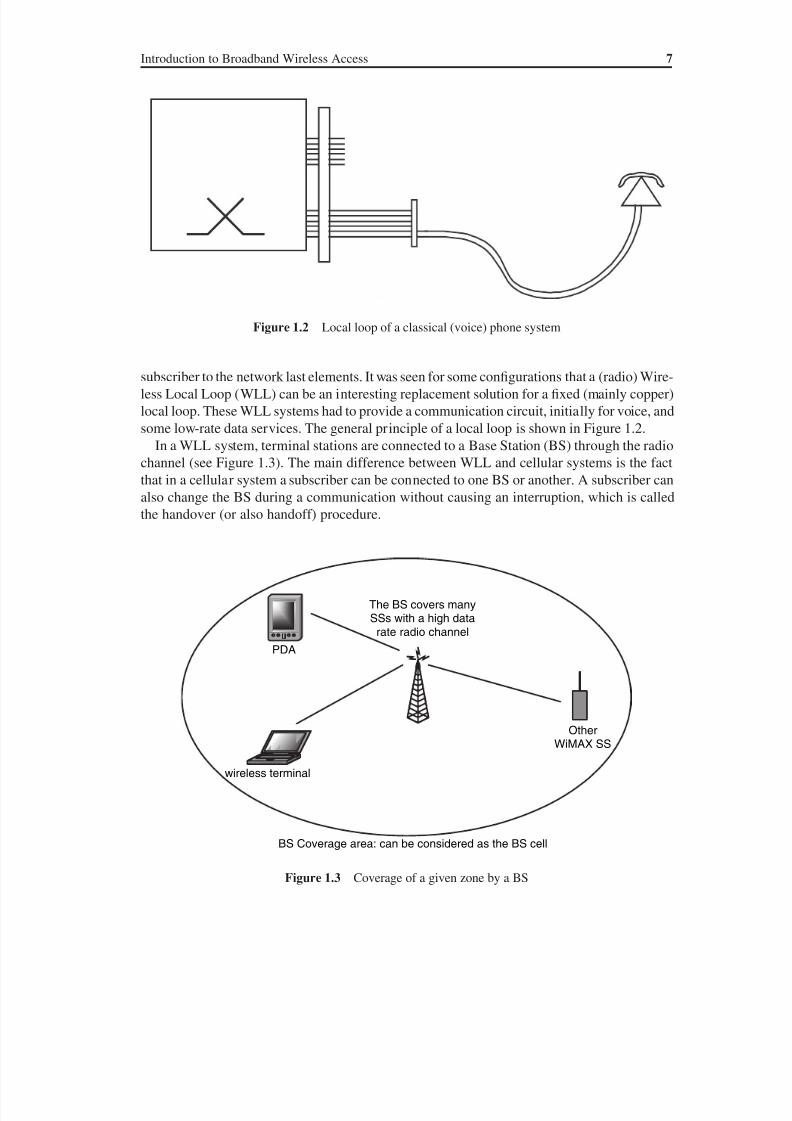
some low-rate data services. The general principle of a local loop is shown in Figure 1.2.
In a WLL system, terminal stations are connected to a Base Station (BS) through the radio
channel (see Figure 1.3). The main difference between WLL and cellular systems is the fact
that in a cellular system a subscriber can be connected to one BS or another. A subscriber can
also change the BS during a communication without causing an interruption, which is called
the handover (or also handoff) procedure.
Figure 1.2 Local loop of a classical (voice) phone system
Figure 1.3 Coverage of a given zone by a BS
wireless terminal
The BS covers manySSs with a high datarate radio channel
PDA
OtherWiMAX SS
BS Coverage area: can be considered as the BS cell
8/10/2019 WiMax-Tech for BBW Access
http://slidepdf.com/reader/full/wimax-tech-for-bbw-access 29/293
8 WiMAX: Technology for Broadband Wireless Access
Several technologies have been proposed for WLL systems, also known as cordless phone
systems (or also cordless systems). After analogue systems, mainly proprietary, a digital sys-
tem was proposed, CT2/CAI (Cordless Telephone 2/Common Air Interface), in 1991. With
CT2/CAI, the occupation of one (voice) user is 100 kHz.
The European Telecommunications Standards Institute (ETSI) published a WLL cordlesssystem in 1992 named DECT (Digital Enhanced Cordless Telecommunications). The range
of DECT equipments is up to a few hundred metres. DECT works in the 1.9 GHz bandwidth.
DECT is a digital TDMA (Time Division Multiple Access) suited for voice and low data
rate applications, in the order of tens of kb/s. Some evolutions of DECT, featuring many slots
per user, propose higher data rates up to hundreds of kb/s. DECT has a relatively high suc-
cess rate nowadays, yet it is a capacity-limited system as TDMA-only systems do not use the
bandwidth very efficiently (a user taking many slots leaves very few resources for other us-
ers). The wide use of WLL systems for phone communications and some other low data rate
communications gave way to high data rate BWA systems, introduced in Section 1.2.2 above
and described in further detail in the next section.
1.3 Applications of BWA
As already introduced above with IEEE 802.16, a BWA system is a high data rate (of the order
of Mb/s) WMAN or WWAN. A BWA system can be seen as an evolution of WLL systems
mainly featuring significantly higher data rates. While WLL systems are mainly destined for
voice communications and low data rate (i.e. smaller than 50 kb/s), BWAs’ are intended to
deliver data flows in Mb/s (or a little lower).
The first application of BWA is fixed-position high data rate access. This access can then
evidently be used for Internet, TV and other expected high data rate applications such as
Video-on-Demand (VoD). It will also surely be used for other applications that are not really
apparent yet. In one word, the first target of BWA is to be a wireless DSL (Digital Subscriber
Line, originally called the Digital Subscriber Loop) or also a wireless alternative for the
cable. Some business analysts consider that this type of BWA application is interesting only in
countries and regions having relatively underdeveloped telecommunications infrastructure.
Indeed, using WiMAX for the fixed-position wireless Internet in Paris or New York does not
seem economically viable.
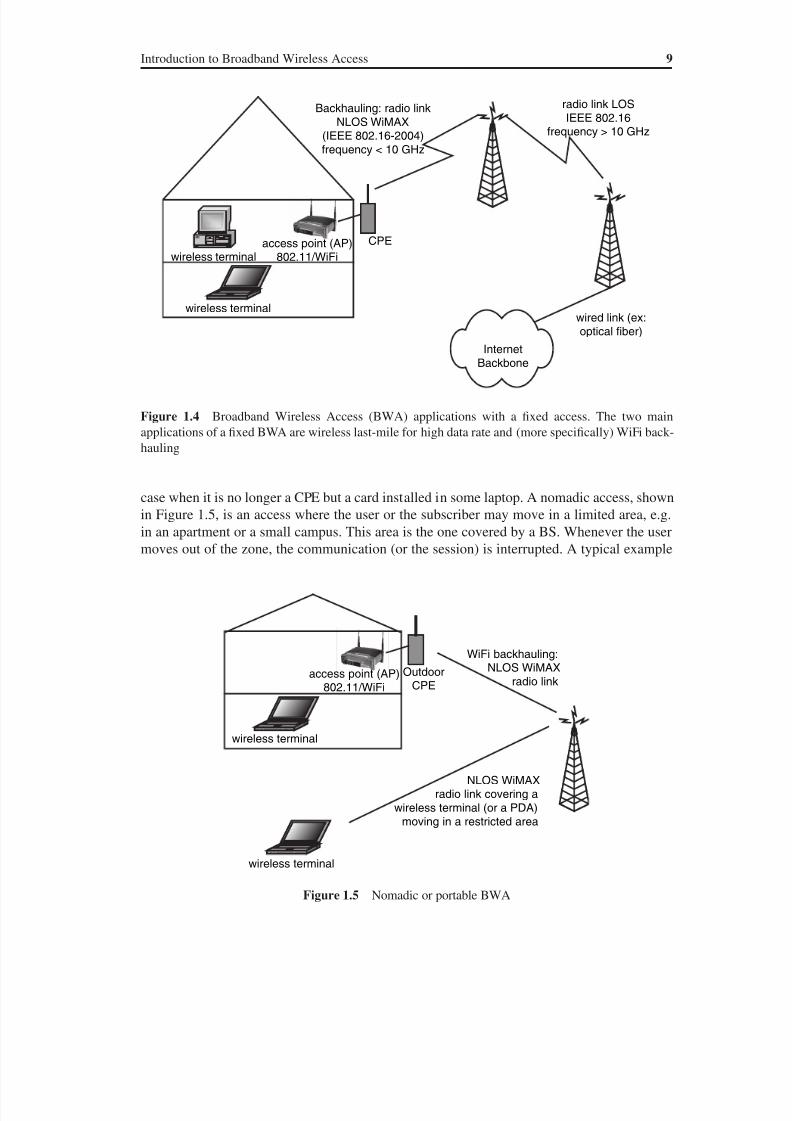
Another possible use of high data rate access with BWA is WiFi Backhauling. As shown in
Figure 1.4, the Internet so-called backbone is linked to a BS which may be in Line-of-Sight
(LOS) of another BS. This has a Non-Line-of-Sight (NLOS) coverage of Subscriber Stations
(SSs). The distinction between IEEE 802.16 NLOS and LOS technologies will be detailed in
Chapter 2.
The SS in Figure 1.4 is a Consumer Premises Equipment (CPE). The CPE is a radio-includ-
ing equipment that realises the link between the BS and the terminal equipment(s) of the user.
After the CPE, the user may install a terminal such as a Personal Computer (PC) or a TV and
may also connect a WiFi Access Point and then a WLAN (the BWA then realizing the WiFi
network backhauling). Hence the two main applications of fixed BWA are the wireless last-mile
for high data rate and (more specifically) WiFi backhauling. As shown in this figure, a wireless
terminal can then be fixed (geographically) or not. This may be the case of a laptop connected
to the CPE with a WiFi connection (see the figure).
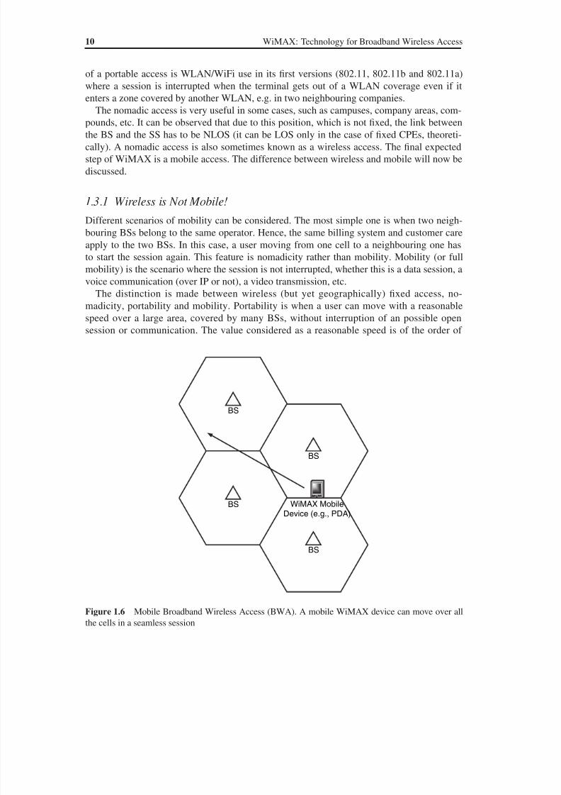
The fixed access is the first use of BWA, the next step being nomadicity (see Section 1.3.1
for the difference between nomadicity and mobility). A first evolution of the SS will be the
8/10/2019 WiMax-Tech for BBW Access
http://slidepdf.com/reader/full/wimax-tech-for-bbw-access 30/293
8/10/2019 WiMax-Tech for BBW Access
http://slidepdf.com/reader/full/wimax-tech-for-bbw-access 31/293
10 WiMAX: Technology for Broadband Wireless Access
of a portable access is WLAN/WiFi use in its first versions (802.11, 802.11b and 802.11a)
where a session is interrupted when the terminal gets out of a WLAN coverage even if it
enters a zone covered by another WLAN, e.g. in two neighbouring companies.
The nomadic access is very useful in some cases, such as campuses, company areas, com-
pounds, etc. It can be observed that due to this position, which is not fixed, the link betweenthe BS and the SS has to be NLOS (it can be LOS only in the case of fixed CPEs, theoreti-
cally). A nomadic access is also sometimes known as a wireless access. The final expected
step of WiMAX is a mobile access. The difference between wireless and mobile will now be
discussed.
1.3.1 Wireless is Not Mobile!
Different scenarios of mobility can be considered. The most simple one is when two neigh-
bouring BSs belong to the same operator. Hence, the same billing system and customer care
apply to the two BSs. In this case, a user moving from one cell to a neighbouring one has
to start the session again. This feature is nomadicity rather than mobility. Mobility (or full
mobility) is the scenario where the session is not interrupted, whether this is a data session, a
voice communication (over IP or not), a video transmission, etc.
The distinction is made between wireless (but yet geographically) fixed access, no-
madicity, portability and mobility. Portability is when a user can move with a reasonable
speed over a large area, covered by many BSs, without interruption of an possible open
session or communication. The value considered as a reasonable speed is of the order of
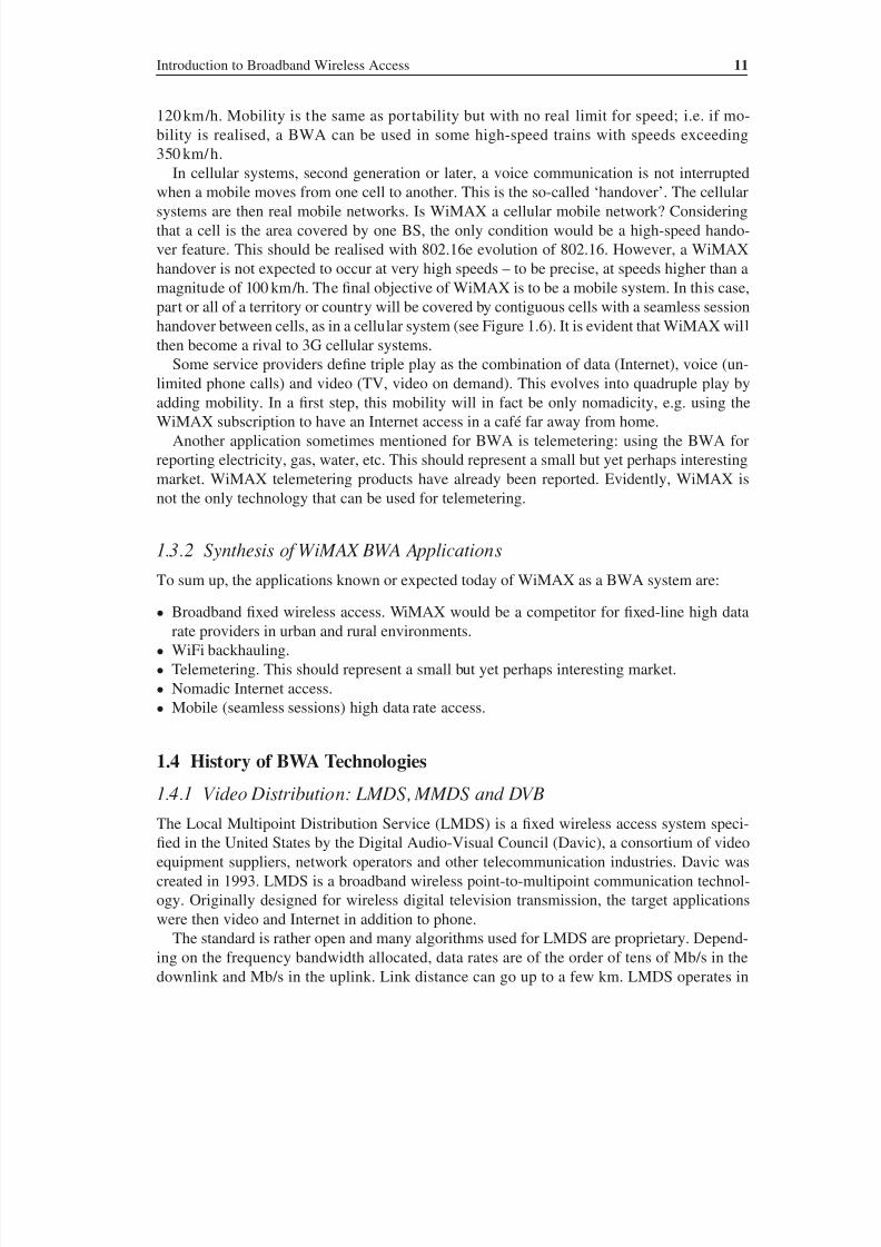
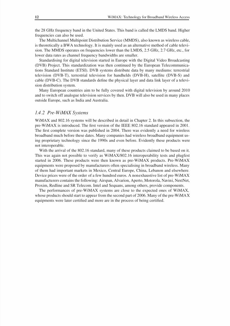
Figure 1.6 Mobile Broadband Wireless Access (BWA). A mobile WiMAX device can move over all
the cells in a seamless session
BS
BS
BS
BS WiMAX MobileDevice (e.g., PDA)
8/10/2019 WiMax-Tech for BBW Access
http://slidepdf.com/reader/full/wimax-tech-for-bbw-access 32/293
Introduction to Broadband Wireless Access 11
120 km/h. Mobility is the same as portability but with no real limit for speed; i.e. if mo-
bility is realised, a BWA can be used in some high-speed trains with speeds exceeding
350 km/h.
In cellular systems, second generation or later, a voice communication is not interrupted
when a mobile moves from one cell to another. This is the so-called ‘handover’. The cellularsystems are then real mobile networks. Is WiMAX a cellular mobile network? Considering
that a cell is the area covered by one BS, the only condition would be a high-speed hando-
ver feature. This should be realised with 802.16e evolution of 802.16. However, a WiMAX
handover is not expected to occur at very high speeds – to be precise, at speeds higher than a
magnitude of 100 km/h. The final objective of WiMAX is to be a mobile system. In this case,
part or all of a territory or country will be covered by contiguous cells with a seamless session
handover between cells, as in a cellular system (see Figure 1.6). It is evident that WiMAX will
then become a rival to 3G cellular systems.
Some service providers define triple play as the combination of data (Internet), voice (un-
limited phone calls) and video (TV, video on demand). This evolves into quadruple play byadding mobility. In a first step, this mobility will in fact be only nomadicity, e.g. using the
WiMAX subscription to have an Internet access in a café far away from home.
Another application sometimes mentioned for BWA is telemetering: using the BWA for
reporting electricity, gas, water, etc. This should represent a small but yet perhaps interesting
market. WiMAX telemetering products have already been reported. Evidently, WiMAX is
not the only technology that can be used for telemetering.
1.3.2 Synthesis of WiMAX BWA Applications
To sum up, the applications known or expected today of WiMAX as a BWA system are:
• Broadband fixed wireless access. WiMAX would be a competitor for fixed-line high data
rate providers in urban and rural environments.
• WiFi backhauling.
• Telemetering. This should represent a small but yet perhaps interesting market.
• Nomadic Internet access.
• Mobile (seamless sessions) high data rate access.
1.4 History of BWA Technologies
1.4.1 Video Distribution: LMDS, MMDS and DVB
The Local Multipoint Distribution Service (LMDS) is a fixed wireless access system speci-
fied in the United States by the Digital Audio-Visual Council (Davic), a consortium of video
equipment suppliers, network operators and other telecommunication industries. Davic was
created in 1993. LMDS is a broadband wireless point-to-multipoint communication technol-
ogy. Originally designed for wireless digital television transmission, the target applications
were then video and Internet in addition to phone.
The standard is rather open and many algorithms used for LMDS are proprietary. Depend-
ing on the frequency bandwidth allocated, data rates are of the order of tens of Mb/s in the
downlink and Mb/s in the uplink. Link distance can go up to a few km. LMDS operates in
8/10/2019 WiMax-Tech for BBW Access
http://slidepdf.com/reader/full/wimax-tech-for-bbw-access 33/293
12 WiMAX: Technology for Broadband Wireless Access
the 28 GHz frequency band in the United States. This band is called the LMDS band. Higher
frequencies can also be used.
The Multichannel Multipoint Distribution Service (MMDS), also known as wireless cable,
is theoretically a BWA technology. It is mainly used as an alternative method of cable televi-
sion. The MMDS operates on frequencies lower than the LMDS, 2.5 GHz, 2.7 GHz, etc., forlower data rates as channel frequency bandwidths are smaller.
Standardising for digital television started in Europe with the Digital Video Broadcasting
(DVB) Project. This standardization was then continued by the European Telecommunica-
tions Standard Institute (ETSI). DVB systems distribute data by many mediums: terrestrial
television (DVB-T), terrestrial television for handhelds (DVB-H), satellite (DVB-S) and
cable (DVB-C). The DVB standards define the physical layer and data link layer of a televi-
sion distribution system.
Many European countries aim to be fully covered with digital television by around 2010
and to switch off analogue television services by then. DVB will also be used in many places
outside Europe, such as India and Australia.
1.4.2 Pre-WiMAX Systems
WiMAX and 802.16 systems will be described in detail in Chapter 2. In this subsection, the
pre-WiMAX is introduced. The first version of the IEEE 802.16 standard appeared in 2001.
The first complete version was published in 2004. There was evidently a need for wireless
broadband much before these dates. Many companies had wireless broadband equipment us-
ing proprietary technology since the 1990s and even before. Evidently these products were
not interoperable.
With the arrival of the 802.16 standard, many of these products claimed to be based on it.
This was again not possible to verify as WiMAX/802.16 interoperability tests and plugfest
started in 2006. These products were then known as pre-WiMAX products. Pre-WiMAX
equipments were proposed by manufacturers often specialising in broadband wireless. Many
of them had important markets in Mexico, Central Europe, China, Lebanon and elsewhere.
Device prices were of the order of a few hundred euros. A nonexhaustive list of pre-WiMAX
manufacturers contains the following: Airspan, Alvarion, Aperto, Motorola, Navini, NextNet,
Proxim, Redline and SR Telecom. Intel and Sequans, among others, provide components.
The performances of pre-WiMAX systems are close to the expected ones of WiMAX,
whose products should start to appear from the second part of 2006. Many of the pre-WiMAX
equipments were later certified and more are in the process of being certified.
8/10/2019 WiMax-Tech for BBW Access
http://slidepdf.com/reader/full/wimax-tech-for-bbw-access 34/293
2WiMAX Genesis and Framework
2.1 IEEE 802.16 Standard
The main features of IEEE 802.16/WiMAX technology are the following:
• (Carrier) frequency11 GHz. For the moment, the frequency bands considered are 2.5 GHz,
3.5 GHz and 5.7 GHz.
• OFDM. The 802.16 is (mainly) built on the Orthogonal Frequency Division Multiplexing
(OFDM) transmission technique known for its high radio resource use efficiency.
• Data rates. A reasonable number is 10 Mb/s. Reports have given more ambitious figures
going up to 70 Mb/s or even 100 Mb/s. These values would be for a very good state of the
radio channel and for a very small cell capacity, making these values too optimistic for the
moment.
• Distance. Up to 20 km, a little less for indoor equipments.
As mentioned in Chapter 1, the IEEE 802.16 standard is the network technology used for
WiMAX. The IEEE 802.16 working group for BWA was created in 1999. It was divided into
two working groups:
• 802.16a, centre frequency within the interval 2–11 GHz. This technology will then be used
for WiMAX.
• 802.16, with a frequency value interval of 10–66 GHz.
Many documents were approved and published by 802.16 subcommittees. They are presentedin Table 2.1.
As stated in 802.16-2004 [1], this standard revises and consolidates IEEE standards 802.16-
2001, 802.16a-2003 and 802.16c-2002. Before getting to 802.16-2004, a revision called
802.16d was started in September 2003 with the objective of taking into account the ETSI
HiperMAN BWA standard [3]. The 802.16d project was later concluded with the approval
of the 802.16-2004 document and the withdrawal of the earlier 802.16 documents, including
the a, b and c amendments. Confusingly enough, some people still refer to 802.16-2004 as
802.16d (or even 16d).
WiMAX: Technology for Broadband Wireless Access Loutfi Nuaymi
© 2007 John Wiley & Sons, Ltd. ISBN: 0-470-02808-4

8/10/2019 WiMax-Tech for BBW Access
http://slidepdf.com/reader/full/wimax-tech-for-bbw-access 35/293
14 WiMAX: Technology for Broadband Wireless Access
2.1.1 From 802.16-2004 to 802.16e802.16-2004 was definitely very useful, replacing a set of documents all describing different
parts of the same technology, with different modification directions. Yet, after its publication,
it still needed an upgrade, mainly for the addition of mobility features. Other features were
needed and some errors had to be corrected. This gave way to 802.16e amendment approved
on December 7, 2005 and published in February 2006 [2].
It should be noted that 802.16e is not a standalone document. It only proposes (sometimes
important) changes and additions to the 802.16-2004 text. Hence, a person wishing to read
the details of specific information in 802.16, e.g. ‘What is the frame format in 802.16?’ has
first to read the related part of 802.16-2004 and then go on to read the possible changesthat took place in 802.16e. It was reported that the IEEE intention was to have a unique
document resulting from 16-2004 and 16e fusion, called 802.16-2005. However, by sum-
mer 2006, this document does not exist (to the best of the author’s knowledge). However,
the 802.16-2004 standard and 802.16e amendment are sometimes referred to as the IEEE
802.16-2005 standard.
The main differences of 802.16e with regard to 802.16-2004 are the following (the list is
not exhaustive):
• Mobile stations (MS) appear. A station in a mobile telecommunication service is intended
to be used while in motion or during halts at unspecified points. However, a 802.16e MS is
also a subscriber station (SS).
• MAC layer handover procedures. There are two types of handover (see Chapter 14).
• Power save modes (for mobility-supporting MSs): sleep mode and idle mode (see Chapter 14).
• SOFDMA (Scalable OFDMA). More generally, the OFDMA PHY layer, i.e. Section 8.4
of the 802.16 standard, was completely rewritten between 16-2004 and 16e. Although the
word SOFDMA does not appear in the 802.16e document, it is the type of standardised
OFDMA. For OFDMA and SOFDMA, see Chapter 5.
• Security (privacy sublayer). The security of 16-2004 is completely updated (see Chapter 15).
• Multiple-Input Multiple-Output (MIMO) and Adaptive Antenna System (AAS) techniques,
both already introduced in 802.16-2004, have many enhancement and implementation de-
tails provided in 802.16e (see Chapter 12).
• Multicast and broadcast services (MBS) feature.
Table 2.1 Main IEEE 802.16 documents
Date and name of the document Description
Dec. 2001, 802.16 10–66 GHz; line-of-sight (LOS); 2–5 km;
channel bandwidth values: 20, 25 and 28 MHzJan. 2003, 802.16a 2–11 GHz; non-line-of-sight (NLOS)
Oct. 2004, 802.16-2004 Revises and consolidates previous 802.16
standards; replaces 16a and 16; 5–50 km
7 Dec. 2005, 802.16 approves 802.16e
amendment of 802.16-2004
Mobility; OFDMA (SOFDMA)
Other 802.16 amendments approved or at draft
stage: 802.16f, 802.16g, 802.16f, etc.
See Section 2.5
8/10/2019 WiMax-Tech for BBW Access
http://slidepdf.com/reader/full/wimax-tech-for-bbw-access 36/293
WiMAX Genesis and Framework 15
• A new (fifth) QoS class: ertPS. (In addition to 802.16-2004 rtPS), ertPS Class supports real-
time service flows that generate variable-size data packets on a periodic basis, e.g. VoIP
with silence suppression.
• Other: the Low-Density Parity Check (LDPC) code is an optional channel coding, etc.
2.2 WiMAX ForumIEEE 802 standards provide only the technology. It is then needed to have other organisms
for the certification of conformity and the verification of interoperability. In the case of IEEE
802.11 WLAN, the Wireless Fidelity Alliance (WiFi or Wi-Fi) Consortium had a major role
in the success of the WiFi technology, as it is now known. Indeed, the fact that two WiFi
certified IEEE 802.11 WLAN devices are guaranteed to work together paved the way for the
huge spread of WiFi products.
The certification problem was even more important for WiMAX as many product manu-
facturers claimed they had verified the 802.16 standard (for pre-WiMAX products, see Sec-
tion 1.4.2). The WiMAX (Worldwide Interoperability for Microwave Access) Forum (www.
wimaxforum.org) was created in June 2001 with the objective that the WiMAX Forum playsexactly the same role for IEEE 802.16 as WiFi for 802.11. The WiMAX Forum provides
certification of conformity, compatibility and interoperability of IEEE 802.16 products. After
a period of low-down, the WiMAX Forum was reactivated in April 2003. Some sources
indicate this latter date as the date of the creation of the WiMAX Forum. Intel and Nokia,
along with others, played a leading role in the creation of the Forum. Then Nokia became
less active, claiming that it wished to concentrate on 3G. However, Nokia is again an active
player of WiMAX.
WiMAX Forum members are system and semiconductors manufacturers, other equipment
vendors, network operators, academics and other telecommunication actors. A complete list
of the WiMAX Forum members can be found on the Forum Member Roster web page. A
nonexhaustive list of WiMAX members is proposed in Table 2.2.
The site of the WiMAX Forum indicates that its objective is to facilitate the deployment
of broadband wireless networks based on the IEEE 802.16 standard by ensuring the compat-
ibility and interoperability of broadband wireless equipment. More details about WiMAX
certification are given in Section 2.3.
2.2.1 WiMAX Forum Working Groups
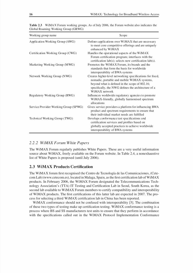
The WiMAX Forum is organised into Working Groups (WGs). The scope of these WGs is
given in Table 2.3, as indicated on the WiMAX Forum website.
The WiMAX network architecture as defined by the NWG is described in Chapter 13.
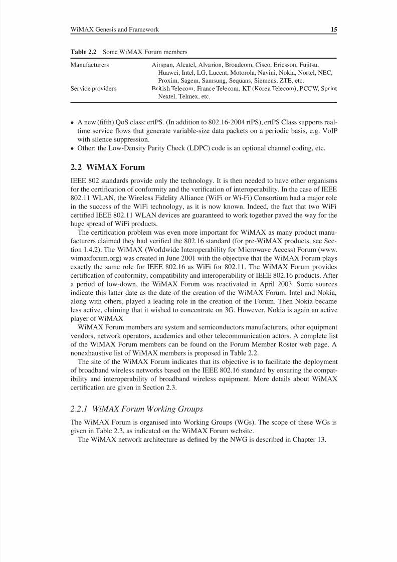
Table 2.2 Some WiMAX Forum members
Manufacturers Airspan, Alcatel, Alvarion, Broadcom, Cisco, Ericsson, Fujitsu,
Huawei, Intel, LG, Lucent, Motorola, Navini, Nokia, Nortel, NEC,
Proxim, Sagem, Samsung, Sequans, Siemens, ZTE, etc.
Service providers British Telecom, France Telecom, KT (Korea Telecom), PCCW, Sprint
Nextel, Telmex, etc.
8/10/2019 WiMax-Tech for BBW Access
http://slidepdf.com/reader/full/wimax-tech-for-bbw-access 37/293
16 WiMAX: Technology for Broadband Wireless Access
2.2.2 WiMAX Forum White Papers
The WiMAX Forum regularly publishes White Papers. These are a very useful information
source about WiMAX, freely available on the Forum website. In Table 2.4, a nonexhaustive
list of White Papers is proposed (until July 2006).
2.3 WiMAX Products Certification
The WiMAX forum first recognised the Centro de Tecnología de las Comunicaciones, (Cete-
com Lab) (www.cetecom.es), located in Malaga, Spain, as the first certification lab of WiMAX
products. In February 2006, the WiMAX Forum designated the Telecommunications Tech-
nology Association’s (TTA) IT Testing and Certification Lab in Seoul, South Korea, as the
second lab available to WiMAX Forum members to certify compatibility and interoperability
of WiMAX products. The first certifications of this latter lab are expected in 2007. The pro-
cess for selecting a third WiMAX certification lab in China has been reported.
WiMAX conformance should not be confused with interoperability [5]. The combination
of these two types of testing make up certification testing. WiMAX conformance testing is aprocess where BS and SS manufacturers test units to ensure that they perform in accordance
with the specifications called out in the WiMAX Protocol Implementation Conformance
Table 2.3 WiMAX Forum working groups. As of July 2006, the Forum website also indicates the
Global Roaming Working Group (GRWG)
Working group name Scope
Application Working Group (AWG) Defines applications over WiMAX that are necessaryto meet core competitive offerings and are uniquely
enhanced by WiMAX
Certification Working Group (CWG) Handles the operational aspects of the WiMAX
Forum certification program; interfaces with the
certification lab(s); selects new certification lab(s).
Marketing Working Group (MWG) Promotes the WiMAX Forum, its brands and the
standards that form the basis for worldwide
interoperability of BWA systems
Network Working Group (NWG) Creates higher-level networking specifications for fixed,
nomadic, portable and mobile WiMAX systems,
beyond what is defined in the scope of 802.16;specifically, the NWG defines the architecture of a
WiMAX network
Regulatory Working Group (RWG) Influences worldwide regulatory agencies to promote
WiMAX-friendly, globally harmonised spectrum
allocations
Service Provider Working Group (SPWG) Gives service providers a platform for influencing BWA
product and spectrum requirements to ensure that
their individual market needs are fulfilled
Technical Working Group (TWG) Develops conformance test specifications and
certification services and profiles based on
globally accepted practices to achieve worldwide
interoperability of BWA systems

8/10/2019 WiMax-Tech for BBW Access
http://slidepdf.com/reader/full/wimax-tech-for-bbw-access 38/293
WiMAX Genesis and Framework 17
Table 2.4 WiMAX Forum (www.wimaxforum.org) White Papers, last update: July 2006. Table
was drawn with the help of Ziad Noun
Title
Date of latest
version
Number
of pages Brief description
IEEE 802.16a standard and
WiMAX – Igniting BWA
Date not
mentioned
7 An overview of IEEE 802.16a
standard, its PHY and MAC
layers; talks also about the WiFi
versus WiMAX scalability
Regulatory position and goals
of the WiMAX Forum
August 2004 6 Describes the goals of WiMAX
Forum (interoperability of
broadband wireless products);
describes also the initial frequency
bands (license and license exempt)
Business case for fixed wireless
access in emerging markets
June 2005 22 Describes the characteristics of
emerging markets and discusses
the service and revenue
assumptions for business case
analysis (urban, suburban, rural)
WiMAX deployment
considerations for fixed
wireless access in the
2.5 GHz and 3.5 GHz
licensed bands
June 2005 21 About the licensed spectrum for
WMAN, the radio characteristics,
the range and the capacity of
the system in different scenarios
(urban, suburban, etc.)
Business case models for fixed
broadband wireless access
based on WiMAX technology
and the 802.16 standard
October 2004 24 Describes the WiMAX architecture
and applications, the business case
considerations and assumptions and
the services offered by WiMAX
Initial certification profiles
and the European regulatory
framework
September 2004 4 Describes the profiles currently
identified for the initial certification
process and the tentative profiles
under consideration for the next
round of the certification process
WiMAX’s technology for LOS
and NLOS environments.
August 2004 10 About the characteristics of
OFDM and the other solutions
used by WiMAX to solve the
problems resulting from NLOS(subchannelisation, directional
antennas, adaptive modulation,
error correction techniques, power
control, etc.)
Telephony’s ‘Complete Guide
to WiMAX’
May 2004 10 About WiMAX marketing and
policy considerations
What WiMAX Forum certified
products will bring to Wi-Fi
June 2004 10 Why WiFi is used in WiMAX,
the OFDM basics, the 802.16/
HiperMAN PHY and MAC
layers, the operator requirements
for BWA systems and the productscertification
(continued overleaf )
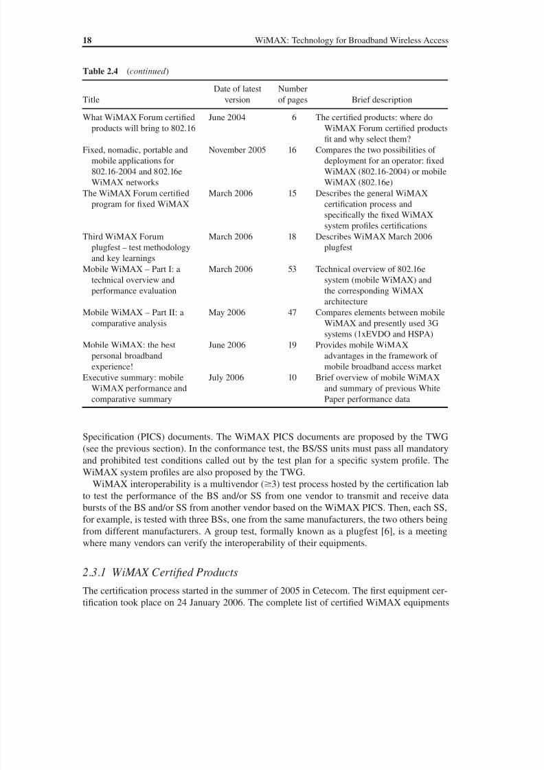
8/10/2019 WiMax-Tech for BBW Access
http://slidepdf.com/reader/full/wimax-tech-for-bbw-access 39/293
8/10/2019 WiMax-Tech for BBW Access
http://slidepdf.com/reader/full/wimax-tech-for-bbw-access 40/293
WiMAX Genesis and Framework 19
can be found on www.wimaxforum.org/kshowcase/view. All these equipments were certified
for IEEE 802.16-2004 profiles (fixed WiMAX). Certification of equipments based on mobile
WiMAX profiles (or, soon on mobile WiMAX equipments) should take place in the first half
of 2007.
The certified equipments are from the three types of WiMAX manufacturers:
• pre-WiMAX experienced companies;
• companies initially more specialised in cellular network products, e.g. Motorola, which is
in these two categories;
• newcomers that started business specifically for WiMAX products.
2.4 Predicted Products and Deployment Evolution
2.4.1 Product Types
Different types of WiMAX products are expected.
First step: CPE products. These CPE products are first outdoor (see Figure 1.5) and then indoor.
These are the products already certified (mainly outdoor for the moment). For CPEs WiMAX
products, some providers may require that only authorised installers should install the equip-
ment for subscribers. It can be expected that self-installed CPEs will quickly appear.
Second step: devices installed on portable equipments. These portable equipments will first
be laptops. It is expected (and probably already realised by the time of publication of this
book) that these laptop-installed WiMAX devices may have a USB (Universal Serial Bus)
connection, PCMCIA (Personal Computer Memory Card International Association) (lessprobable), a PCI (Peripheral Component Interconnect) connection or another type of con-
nection. In this case, a WiMAX subscriber can move in a limited area (the one covered by
the BS) and then nomadicity will be realised.
Later, a WiMAX internal factory-installed device in laptops will probably appear, as is
already the case for WiFi. This will clearly produce a situation where WiMAX will spread
widely. The difficulties encountered are of two types:
• manufacturing devices small enough; this do not really seem to be a difficult problem;
• radio engineering and deployment considerations, where the technology and deployment
techniques should be mature enough to have a high concentration of subscribers.
Final step: WiMAX devices in PDA and other handheld devices such as a mobile phone. For
this, WiMAX devices need to be even smaller. They could take the shape of the SIM (Sub-
scriber Identity Module) cards presently used for cellular systems (second and third gen-
eration). Thus WiMAX will be a mobile network and then a competitor for 3G systems.
2.4.2 Products and Deployment Timetable
Once WiMAX evolution is described, we need to know about the timetable of these products.
What about the network deployments? As of today a large number of pre-WiMAX networks
exist around the world, both in developed and developing countries. These deployments are
often on a scale smaller than the whole country, typically limited to a region or an urban

8/10/2019 WiMax-Tech for BBW Access
http://slidepdf.com/reader/full/wimax-tech-for-bbw-access 41/293
8/10/2019 WiMax-Tech for BBW Access
http://slidepdf.com/reader/full/wimax-tech-for-bbw-access 42/293
WiMAX Genesis and Framework 21
Amendments at the pre-draft stage are the following:
• 802.16h – Improved Coexistence Mechanisms for License-Exempt Operation;
• 802.16i – Mobile Management Information Base, where the objective is to add mobility
support to the 802.16f fixed MIB standard.
Work on the 802.16j amendment draft has been reported, which concerns the Multi-hop
Mobile Radio (MMR). Hence, 802.16j should provide some enhancement for the Mesh mode.
The Project Authorization Request (PAR) of 802.16j was approved in March 2006.
2.6 The Korean Cousin: WiBro
South Korea has definitely an advantage in modern telecommunication networks, whether in
ADSL (Asymmetric Digital Subscriber Line) or 3G figures. The TTA PG302 BWA standard
was approved in June 2004 by the TTA (Telecommunications Technology Association, theKorean standardisation organisation) and is known as WiBro (Wireless Broadband). This
standard has the support of leading people in the Korean telecommunication industry.
Originally sought as a competitor of WiMAX, an agreement was found by the end of
2004, while 802.16e was still under preparation, between 802.16 backers (including Intel) and
WiBro backers in order to have WiBro products certified as WiMAX equipments.
WiBro licenses were assigned in Korea in January 2005. The three operators are Korea
Telecom (KT), SK Telecom (SKT) and Hanaro Telecom. Pilot networks are already in place
(April 2006). Relatively broad coverage public commercial offers should start before the end
of 2006. WiBro planned deployments in other countries have been reported (among others,
Brazil). This should give WiBro an early large-scale BWA deployment and then provide im-portant field technical and market observations.

8/10/2019 WiMax-Tech for BBW Access
http://slidepdf.com/reader/full/wimax-tech-for-bbw-access 43/293
3Protocol Layers and Topologies
In this chapter, the protocol layer architecture of WiMAX/802.16 is introduced. The main
objectives of each sublayer are given as well as the global functions that they realise. Links
are provided to the chapters of this book where each of these sublayers or procedures are
described in much more detail.
3.1 The Protocol Layers of WiMAX
The IEEE 802.16 BWA network standard applies the so-called Open Systems Interconnec-
tion (OSI) network reference seven-layer model, also called the OSI seven-layer model. This
model is very often used to describe the different aspects of a network technology. It starts
from the Application Layer, or Layer 7, on the top and ends with the PHYsical (PHY) Layer,
or Layer 1, on the bottom (see Figure 3.1).The OSI model separates the functions of different protocols into a series of layers, each
layer using only the functions of the layer below and exporting data to the layer above. For ex-
ample, the IP (Internet Protocol) is in Layer 3, or the Routing Layer. Typically, only the lower
layers are implemented in hardware while the higher layers are implemented in software.
The two lowest layers are then the Physical (PHY) Layer, or Layer 1, and the Data Link
Layer, or Layer 2. IEEE 802 splits the OSI Data Link Layer into two sublayers named Logical
Link Control (LLC) and Media Access Control (MAC). The PHY layer creates the physi-
cal connection between the two communicating entities (the peer entities), while the MAC
layer is responsible for the establishment and maintenance of the connection (multiple access,
scheduling, etc.).The IEEE 802.16 standard specifies the air interface of a fixed BWA system supporting
multimedia services. The Medium Access Control (MAC) Layer supports a primarily point-
to-multipoint (PMP) architecture, with an optional mesh topology (see Section 3.7). The
MAC Layer is structured to support many physical layers (PHY) specified in the same stan-
dard. In fact, only two of them are used in WiMAX.
The protocol layers architecture defined in WiMAX/802.16 is shown in Figure 3.2. It
can be seen that the 802.16 standard defines only the two lowest layers, the PHYsical Layer
and the MAC Layer, which is the main part of the Data Link Layer, with the LLC layer
WiMAX: Technology for Broadband Wireless Access Loutfi Nuaymi
© 2007 John Wiley & Sons, Ltd. ISBN: 0-470-02808-4

8/10/2019 WiMax-Tech for BBW Access
http://slidepdf.com/reader/full/wimax-tech-for-bbw-access 44/293
24 WiMAX: Technology for Broadband Wireless Access
very often applying the IEEE 802.2 standard. The MAC layer is itself made of three sub-
layers, the CS (Convergence Sublayer), the CPS (Common Part Sublayer) and the Security
Sublayer.
The dialogue between corresponding protocol layers or entities is made as follows. A Layer
X addresses an XPDU (Layer X Protocol Data Unit) to a corresponding Layer X (Layer X
of the peer entity). This XPDU is received as an (X-1)SDU (Layer X-1 Service Data Unit) byLayer X-1 of the considered equipment. For example, when the MAC Layer of an equipment
PHYsical
Data Link
Network
Transport
Session
Presentation
Application
MAC (MediumAccess Layer)
LLC (LogicalLink Control)
Data LinkLayer is
divided in twosublayers
Figure 3.1 The seven-layer OSI model for networks. In WiMAX/802.16, only the two first layers are
defined
OSI Layer 1:PHYsical layer
MAClayer
Service-SpecificConvergenceSublayer (CS)
CS SAP
MAC SAP
MAC CommonPart Sublayer
(CPS)
Security Sublayer
PHY SAP
PHYsical Layer
IEEE802.16
Standardscope
External Network.Example: IP or ATM
MSDU
MPDU(s)
OSI Layer 2:data link
layer
Figure 3.2 Protocol layers of the 802.16 BWA standard. (From IEEE Std. 802.16-2004 [1]. Copyright
IEEE 2004, IEEE. All rights reserved.)
8/10/2019 WiMax-Tech for BBW Access
http://slidepdf.com/reader/full/wimax-tech-for-bbw-access 45/293
Protocol Layers and Topologies 25
sends an MPDU (MAC PDU) to a corresponding equipment, this MPDU is received as a
PSDU (PHYsical SDU) by the PHYsical Layer (see Figure 3.2).
In this chapter, the different layers are introduced. Each of these layers or sublayers and
many of their functions are described in the following sections.
3.2 Convergence Sublayer (CS)
The service-specific Convergence Sublayer (CS), often simply known as the CS, is just above
the MAC CPS sublayer (see Figure 3.2). The CS uses the services provided by the MAC CPS,
via the MAC Service Access Point (SAP). The CS performs the following functions:
• Accepting higher-layer PDUs from the higher layers. In the present version of the standard
[1], CS specifications for two types of higher layers are provided: the asynchronous transfer
mode (ATM) CS and the packet CS. For the packet CS, the higher-layer protocols may be
IP v4 (version 4) or v6 (version 6).• Classifying and mapping the MSDUs into appropriate CIDs (Connection IDentifier). This is
a basic function of the Quality of Service (QoS) management mechanism of 802.16 BWA.
• Processing (if required) the higher-layer PDUs based on the classification.
• An optional function of the CS is PHS (Payload Header Suppression), the process of suppress-
ing repetitive parts of payload headers at the sender and restoring these headers at the receiver.
• Delivering CS PDUs to the appropriate MAC SAP and receiving CS PDUs from the peer
entity.
CS procedures and operations are detailed in Chapter 7.
3.3 Medium Access Control Common Part Sublayer (MAC CPS)
The Common Part Sublayer (CPS) resides in the middle of the MAC layer. The CPS repre-
sents the core of the MAC protocol and is responsible for:
• bandwidth allocation;
• connection establishment;
• maintenance of the connection between the two sides.
The 802.16-2004 standard defines a set of management and transfer messages. The man-
agement messages are exchanged between the SS and the BS before and during the estab-lishment of the connection. When the connection is realised, the transfer messages can be
exchanged to allow the data transmission.
The CPS receives data from the various CSs, through the MAC SAP, classified to particu-
lar MAC connections. The QoS is taken into account for the transmission and scheduling
of data over the PHY Layer. The CPS includes many procedures of different types: frame
construction, multiple access, bandwidth demands and allocation, scheduling, radio resource
management, QoS management, etc. These functions are detailed in Chapters 8 to 11.
3.4 Security Sublayer
The MAC Sublayer also contains a separate Security Sublayer (Figure 3.2) providing
authentication, secure key exchange, encryption and integrity control across the BWA

8/10/2019 WiMax-Tech for BBW Access
http://slidepdf.com/reader/full/wimax-tech-for-bbw-access 46/293
26 WiMAX: Technology for Broadband Wireless Access
system. The two main topics of a data network security are data encryption and authen-
tication. Algorithms realising these objectives should prevent all known security attacks
whose objectives may be denial of service, theft of service, etc.
In the 802.16 standard, encrypting connections between the SS and the BS is made with a
data encryption protocol applied for both ways. This protocol defines a set of supported cryp-tographic suites, i.e. pairings of data encryption and authentication algorithms. An encap-
sulation protocol is used for encrypting data packets across the BWA. This protocol defines
a set of supported cryptographic suites, i.e. pairings of data encryption and authentication
algorithms. The rules for applying those algorithms to an MAC PDU payload are also given.
An authentication protocol, the Privacy Key Management (PKM) protocol is used to
provide the secure distribution of keying data from the BS to the SS. Through this secure
key exchange, due to the key management protocol the SS and the BS synchronize keying
data. The basic privacy mechanisms are strengthened by adding digital-certificate-based
SS authentication to the key management protocol. In addition, the BS uses the PKM pro-
tocol to guarantee conditional access to network services. The 802.16e amendment definedPKMv2 which has the same framework as PKM, re-entitled PKMv1, with some additions
such as new encryption algorithms, mutual authentication between the SS and the BS, sup-
port for a handover and a new integrity control algorithm.
WiMAX security procedures are described in Chapter 15.
3.5 PHYsical Layer
WiMAX is a BWA system. Hence, data are transmitted at high speed on the air interface
through (radio) electromagnetic waves using a given frequency (operating frequency).
The PHY Layer establishes the physical connection between both sides, often in the twodirections (uplink and downlink). As 802.16 is evidently a digital technology, the PHYsical
Layer is responsible for transmission of the bit sequences. It defines the type of signal used,
the kind of modulation and demodulation, the transmission power and also other physical
characteristics.
The 802.16 standard considers the frequency band 2–66 GHz. This band is divided into
two parts:
• The first range is between 2 and 11 GHz and is destined for NLOS transmissions. This was
previously the 802.16a standard. This is the only range presently included in WiMAX.
• The second range is between 11 and 66 GHz and is destined for LOS transmissions. It is
not used for WiMAX.
Five PHYsical interfaces are defined in the 802.16 standard. These physicals interfaces are
summarised in Table 3.1. The five physical interfaces are each described in a specific section of
the 802.16 standard (and amendments). The MAC options (AAS, ARQ, STC, HARQ, etc.) will
be described further in this book (see the Index). Both major duplexing modes, Time Division
Duplexing (TDD) and Frequency Division Duplexing (FDD), can be included in 802.16 systems.
For frequencies in the 10–66 GHz interval (LOS), the WirelessMAN-SC PHY is specified.
For frequencies below 11 GHz (LOS) three PHYsical interfaces are proposed:
• WirelessMAN-OFDM, known as OFDM and using OFDM transmission;
• WirelessMAN-OFDMA, known as OFDMA and using OFDM transmission, and Ortho-
gonal Frequency Division Multiple Access (OFDMA), with the OFDMA PHY Layer,
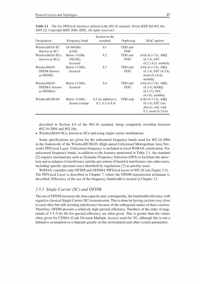
8/10/2019 WiMax-Tech for BBW Access
http://slidepdf.com/reader/full/wimax-tech-for-bbw-access 47/293
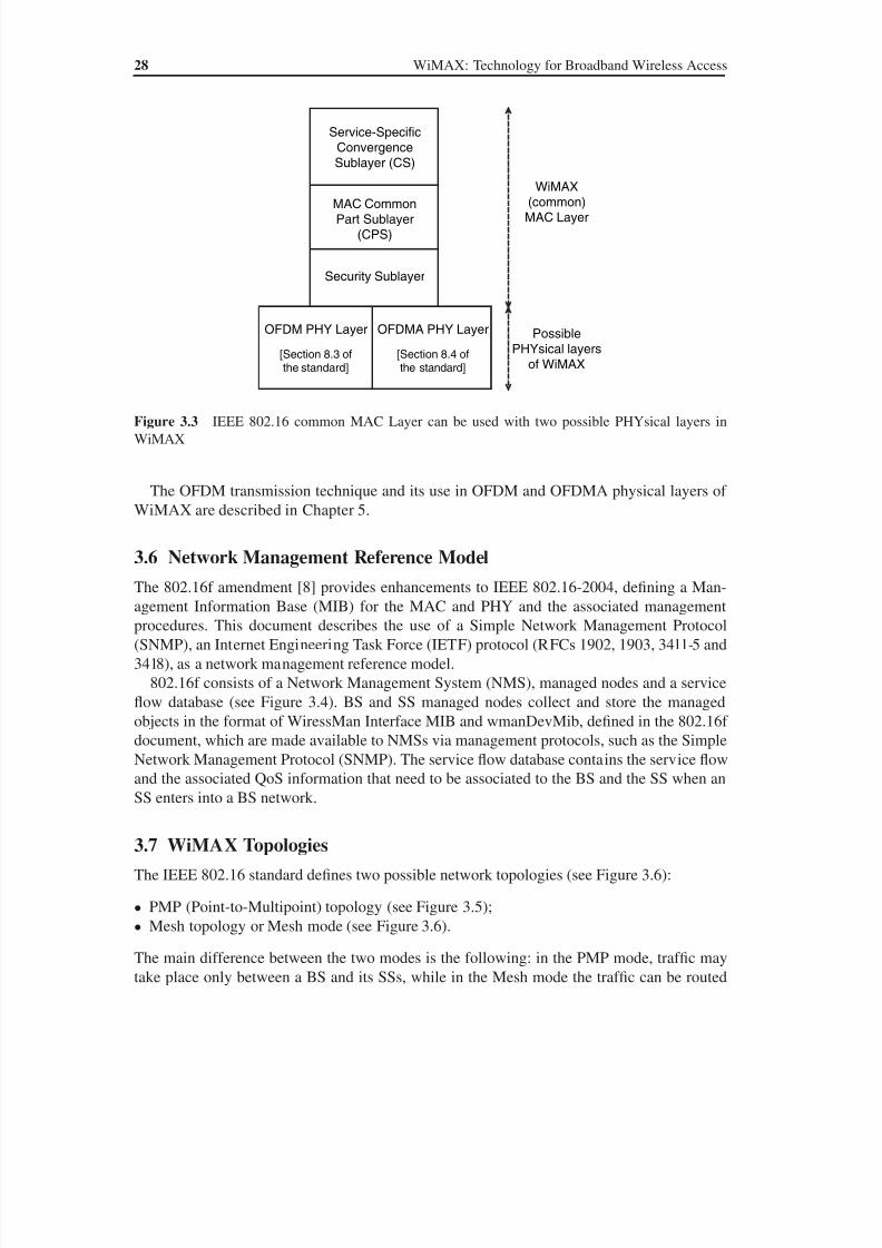
8/10/2019 WiMax-Tech for BBW Access
http://slidepdf.com/reader/full/wimax-tech-for-bbw-access 48/293
28 WiMAX: Technology for Broadband Wireless Access
The OFDM transmission technique and its use in OFDM and OFDMA physical layers of
WiMAX are described in Chapter 5.
3.6 Network Management Reference Model
The 802.16f amendment [8] provides enhancements to IEEE 802.16-2004, defining a Man-
agement Information Base (MIB) for the MAC and PHY and the associated management
procedures. This document describes the use of a Simple Network Management Protocol
(SNMP), an Internet Engineering Task Force (IETF) protocol (RFCs 1902, 1903, 3411-5 and
3418), as a network management reference model.
802.16f consists of a Network Management System (NMS), managed nodes and a service
flow database (see Figure 3.4). BS and SS managed nodes collect and store the managed
objects in the format of WiressMan Interface MIB and wmanDevMib, defined in the 802.16f
document, which are made available to NMSs via management protocols, such as the Simple
Network Management Protocol (SNMP). The service flow database contains the service flowand the associated QoS information that need to be associated to the BS and the SS when an
SS enters into a BS network.
3.7 WiMAX Topologies
The IEEE 802.16 standard defines two possible network topologies (see Figure 3.6):
• PMP (Point-to-Multipoint) topology (see Figure 3.5);
• Mesh topology or Mesh mode (see Figure 3.6).
The main difference between the two modes is the following: in the PMP mode, traffic may
take place only between a BS and its SSs, while in the Mesh mode the traffic can be routed
PossiblePHYsical layers
of WiMAX
Service-SpecificConvergenceSublayer (CS)
MAC CommonPart Sublayer
(CPS)
Security Sublayer
OFDM PHY Layer
[Section 8.3 ofthe standard]
OFDMA PHY Layer
[Section 8.4 ofthe standard]
WiMAX(common)MAC Layer
Figure 3.3 IEEE 802.16 common MAC Layer can be used with two possible PHYsical layers in
WiMAX
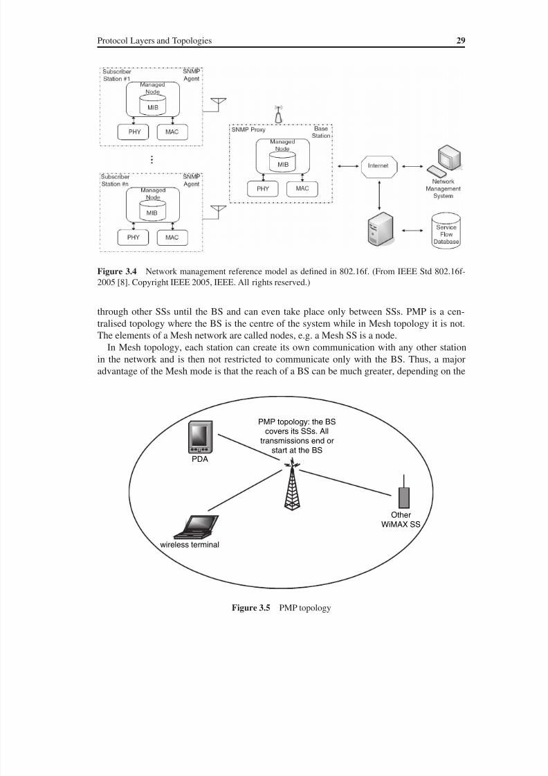
8/10/2019 WiMax-Tech for BBW Access
http://slidepdf.com/reader/full/wimax-tech-for-bbw-access 49/293
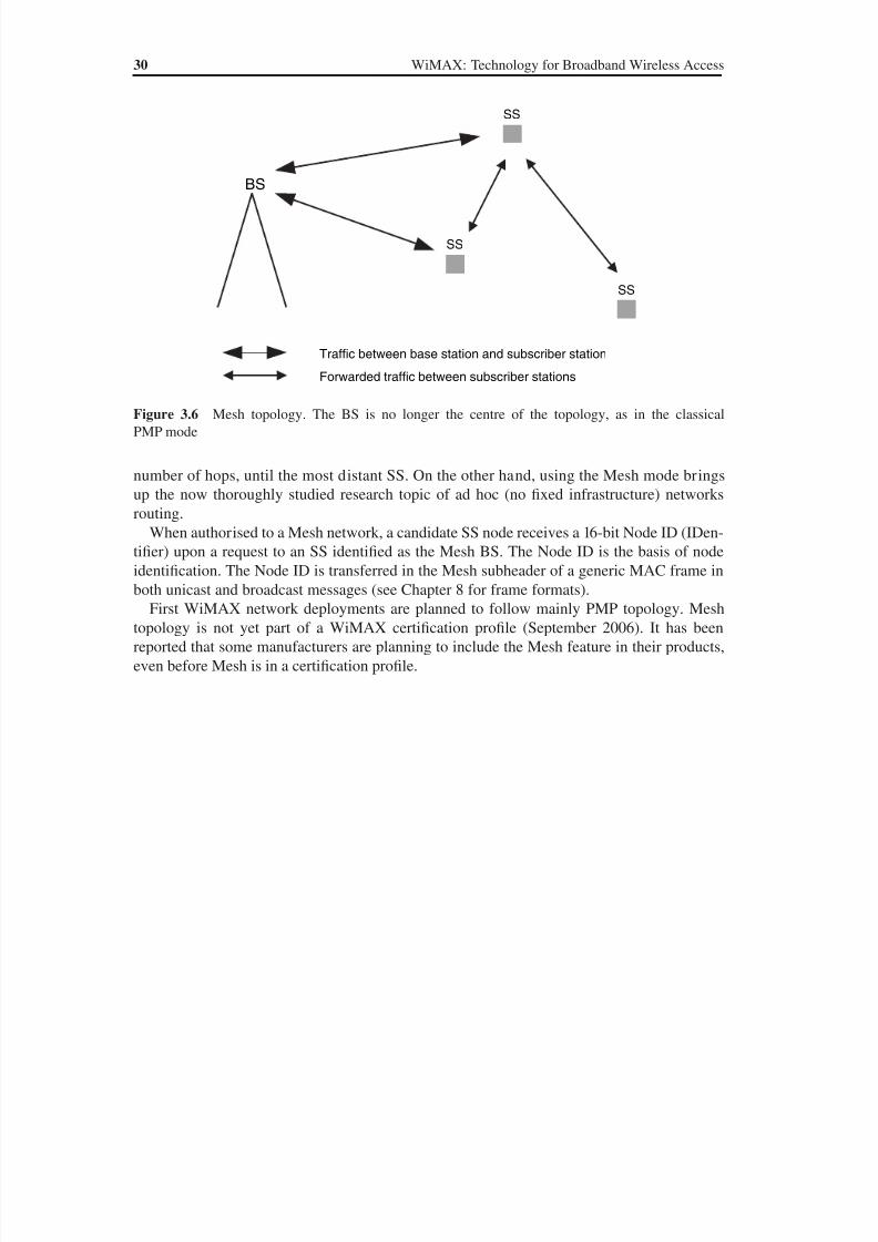
8/10/2019 WiMax-Tech for BBW Access
http://slidepdf.com/reader/full/wimax-tech-for-bbw-access 50/293
30 WiMAX: Technology for Broadband Wireless Access
number of hops, until the most distant SS. On the other hand, using the Mesh mode brings
up the now thoroughly studied research topic of ad hoc (no fixed infrastructure) networks
routing.
When authorised to a Mesh network, a candidate SS node receives a 16-bit Node ID (IDen-
tifier) upon a request to an SS identified as the Mesh BS. The Node ID is the basis of node
identification. The Node ID is transferred in the Mesh subheader of a generic MAC frame inboth unicast and broadcast messages (see Chapter 8 for frame formats).
First WiMAX network deployments are planned to follow mainly PMP topology. Mesh
topology is not yet part of a WiMAX certification profile (September 2006). It has been
reported that some manufacturers are planning to include the Mesh feature in their products,
even before Mesh is in a certification profile.
SS
BS
Traffic between base station and subscriber station
Forwarded traffic between subscriber stations
SS
SS
Figure 3.6 Mesh topology. The BS is no longer the centre of the topology, as in the classical
PMP mode

8/10/2019 WiMax-Tech for BBW Access
http://slidepdf.com/reader/full/wimax-tech-for-bbw-access 51/293
4Frequency Utilisation and SystemProfiles
4.1 The Cellular Concept
The global objective of a wireless network is rather simple: to connect wireless users to a core
network and then to the fixed network. Figure 4.1 illustrates the principle of a Public Land
Mobile Network (PLMN), as defined for second-generation GSM networks.
The first wireless phone systems date back as far as the 1930s. These systems were rather
basic and had very small capacity. The real boost for wireless networks came with the cel-
lular concept invented in the Bell Labs in the 1970s. This simple but also extremely powerful
concept was the following: each base station covers a cell; choose the cells small enough to
reuse the frequencies (see Figure 4.2). Using this concept, it is theoretically possible to cover
a geographical area as large as needed!
The cellular concept was applied to many cellular systems (mostly analogue) defined in the
1980s: AMPS (US), R2000 or Radiocom 2000 (France), TACS (UK), NMT (Scandinavian
countries), etc. These systems being incompatible, a unique European cellular system was
invented, GSM, which is presently used all over the world.
WiMAX applies the same principle: a BS covers the SSs of its cell. In this section, some
elements of the cellular concept theory needed for WiMAX dimensioning are provided. First
sectorisation is reminded.
4.1.1 Sectorisation
A base station site represents a big cost (both as investment, CAPEX, and functioning, OPEX)
for a network operator. Instead of having one site per cell, which is the case for an omnidirec-
tional BS, trisectorisation allows three BSs to be grouped in one site, thus covering three cells
(see Figure 4.3). These cells are then called sectors. Three is not the only possibility. Gener-
ally, it is possible to have a sectorisation with n sectors. Yet, for practical reasons, trisectorisa-
tion is very often used. Sectorisation evidently needs directional antennas. Trisectorisation
needs 120 antennas (such that the three BSs cover the 360).
WiMAX: Technology for Broadband Wireless Access Loutfi Nuaymi
© 2007 John Wiley & Sons, Ltd. ISBN: 0-470-02808-4

8/10/2019 WiMax-Tech for BBW Access
http://slidepdf.com/reader/full/wimax-tech-for-bbw-access 52/293
32 WiMAX: Technology for Broadband Wireless Access
PLMN
(PublicLand
MobileNetwork)
PSTN(WiredPhone
Network)
MobileStation
RadioLink
Fixed(wired)phone
Figure 4.1 Illustration of a Public Land Mobile Network (PLMN) offering a cellular service
Base station
Mobile station
Figure 4.2 The cellular concept: simple and so powerful!
BS
BS
BS
Omnidirectional (360°) antennas
Trisectorisation: threeBSs with directional
(120°) antennas in onegeographical site
Figure 4.3 Omnidirectional antennas and trisectorisation
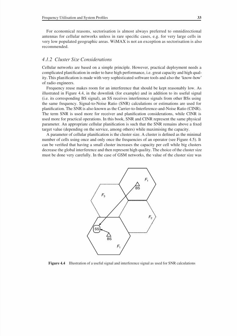
8/10/2019 WiMax-Tech for BBW Access
http://slidepdf.com/reader/full/wimax-tech-for-bbw-access 53/293
Frequency Utilisation and System Profiles 33
For economical reasons, sectorisation is almost always preferred to omnidirectional
antennas for cellular networks unless in rare specific cases, e.g. for very large cells in
very low populated geographic areas. WiMAX is not an exception as sectorisation is also
recommended.
4.1.2 Cluster Size Considerations
Cellular networks are based on a simple principle. However, practical deployment needs a
complicated planification in order to have high performance, i.e. great capacity and high qual-
ity. This planification is made with very sophisticated software tools and also the ‘know-how’
of radio engineers.
Frequency reuse makes room for an interference that should be kept reasonably low. As
illustrated in Figure 4.4, in the downlink (for example) and in addition to its useful signal
(i.e. its corresponding BS signal), an SS receives interference signals from other BSs using
the same frequency. Signal-to-Noise Ratio (SNR) calculations or estimations are used for
planification. The SNR is also known as the Carrier-to-Interference-and-Noise Ratio (CINR).
The term SNR is used more for receiver and planification considerations, while CINR is
used more for practical operations. In this book, SNR and CINR represent the same physical
parameter. An appropriate cellular planification is such that the SNR remains above a fixed
target value (depending on the service, among others) while maximising the capacity.
A parameter of cellular planification is the cluster size. A cluster is defined as the minimal
number of cells using once and only once the frequencies of an operator (see Figure 4.5). It
can be verified that having a small cluster increases the capacity per cell while big clusters
decrease the global interference and then represent high quality. The choice of the cluster size
must be done very carefully. In the case of GSM networks, the value of the cluster size was
F 2
F 1
F 3
BS
BS
SS
F 1
F 2
Figure 4.4 Illustration of a useful signal and interference signal as used for SNR calculations
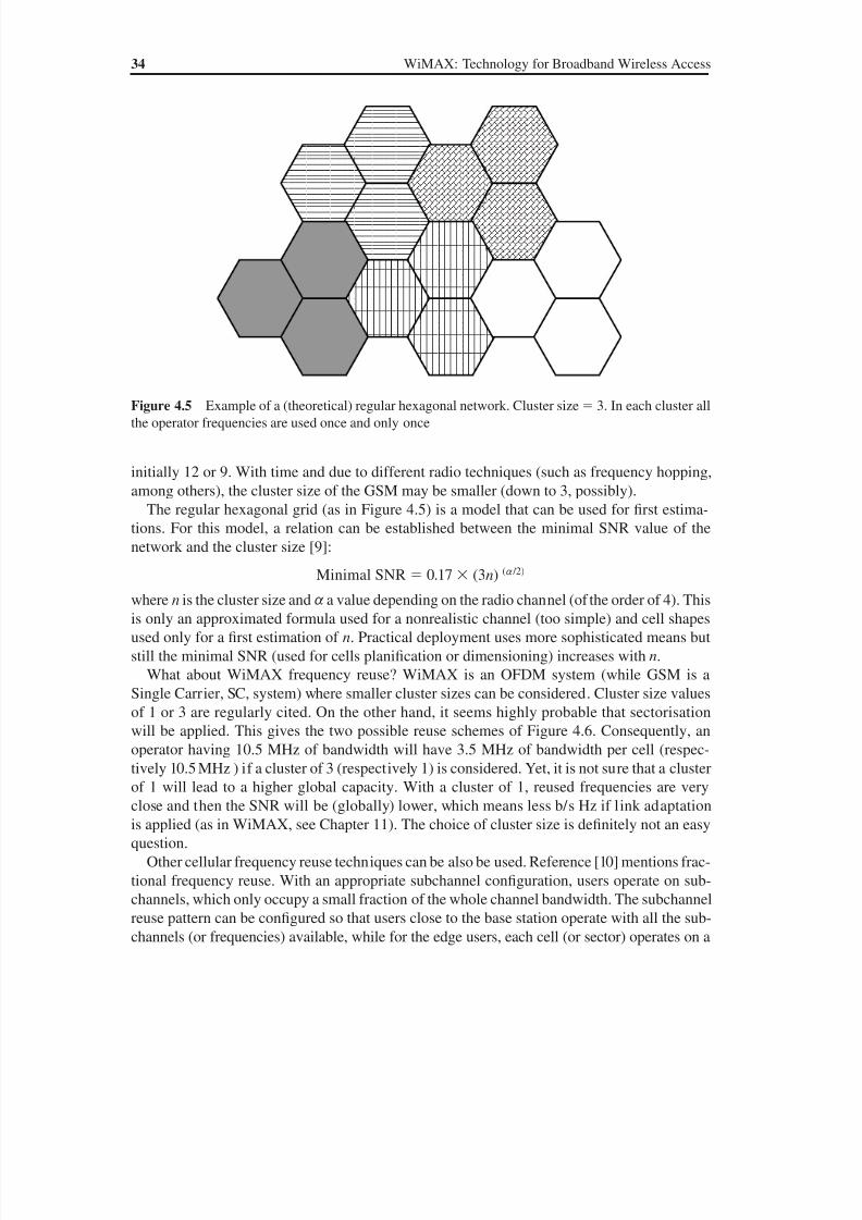
8/10/2019 WiMax-Tech for BBW Access
http://slidepdf.com/reader/full/wimax-tech-for-bbw-access 54/293
34 WiMAX: Technology for Broadband Wireless Access
initially 12 or 9. With time and due to different radio techniques (such as frequency hopping,
among others), the cluster size of the GSM may be smaller (down to 3, possibly).
The regular hexagonal grid (as in Figure 4.5) is a model that can be used for first estima-
tions. For this model, a relation can be established between the minimal SNR value of the
network and the cluster size [9]:
Minimal SNR 0.17 (3n) (a /2)
where n is the cluster size and a a value depending on the radio channel (of the order of 4). This
is only an approximated formula used for a nonrealistic channel (too simple) and cell shapes
used only for a first estimation of n. Practical deployment uses more sophisticated means but
still the minimal SNR (used for cells planification or dimensioning) increases with n.
What about WiMAX frequency reuse? WiMAX is an OFDM system (while GSM is a
Single Carrier, SC, system) where smaller cluster sizes can be considered. Cluster size values
of 1 or 3 are regularly cited. On the other hand, it seems highly probable that sectorisation
will be applied. This gives the two possible reuse schemes of Figure 4.6. Consequently, an
operator having 10.5 MHz of bandwidth will have 3.5 MHz of bandwidth per cell (respec-
tively 10.5 MHz ) if a cluster of 3 (respectively 1) is considered. Yet, it is not sure that a cluster
of 1 will lead to a higher global capacity. With a cluster of 1, reused frequencies are very
close and then the SNR will be (globally) lower, which means less b/s Hz if link adaptation
is applied (as in WiMAX, see Chapter 11). The choice of cluster size is definitely not an easy
question.
Other cellular frequency reuse techniques can be also be used. Reference [10] mentions frac-
tional frequency reuse. With an appropriate subchannel configuration, users operate on sub-
channels, which only occupy a small fraction of the whole channel bandwidth. The subchannel
reuse pattern can be configured so that users close to the base station operate with all the sub-
channels (or frequencies) available, while for the edge users, each cell (or sector) operates on a
Figure 4.5 Example of a (theoretical) regular hexagonal network. Cluster size 3. In each cluster all
the operator frequencies are used once and only once
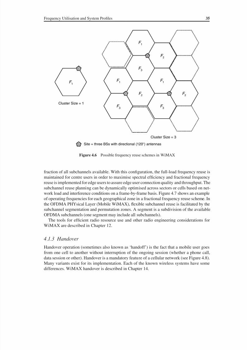
8/10/2019 WiMax-Tech for BBW Access
http://slidepdf.com/reader/full/wimax-tech-for-bbw-access 55/293
Frequency Utilisation and System Profiles 35
fraction of all subchannels available. With this configuration, the full-load frequency reuse is
maintained for centre users in order to maximise spectral efficiency and fractional frequency
reuse is implemented for edge users to assure edge user connection quality and throughput. The
subchannel reuse planning can be dynamically optimised across sectors or cells based on net-
work load and interference conditions on a frame-by-frame basis. Figure 4.7 shows an example
of operating frequencies for each geographical zone in a fractional frequency reuse scheme. In
the OFDMA PHYsical Layer (Mobile WiMAX), flexible subchannel reuse is facilitated by the
subchannel segmentation and permutation zones. A segment is a subdivision of the available
OFDMA subchannels (one segment may include all subchannels).
The tools for efficient radio resource use and other radio engineering considerations for
WiMAX are described in Chapter 12.
4.1.3 Handover
Handover operation (sometimes also known as ‘handoff’) is the fact that a mobile user goes
from one cell to another without interruption of the ongoing session (whether a phone call,
data session or other). Handover is a mandatory feature of a cellular network (see Figure 4.8).
Many variants exist for its implementation. Each of the known wireless systems have some
differences. WiMAX handover is described in Chapter 14.
Site = three BSs with directional (120°) antennas
F 1
F 2
F 1
F 3
F 2
F 1
F 3
F 2
F 1
F 3
Cluster Size = 1
Cluster Size = 3
Figure 4.6 Possible frequency reuse schemes in WiMAX
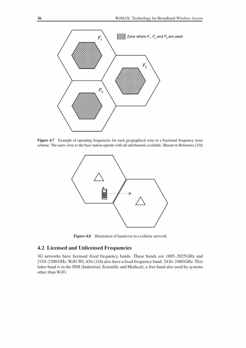
8/10/2019 WiMax-Tech for BBW Access
http://slidepdf.com/reader/full/wimax-tech-for-bbw-access 56/293
36 WiMAX: Technology for Broadband Wireless Access
4.2 Licensed and Unlicensed Frequencies
3G networks have licensed fixed frequency bands. These bands are 1885–2025 GHz and
2110–2200 GHz. WiFi WLANs (11b) also have a fixed frequency band: 2410–2480 GHz. This
latter band is in the ISM (Industrial, Scientific and Medical), a free band also used by systems
other than WiFi.
Zone where F 1, F
2 and F
3 are used
F 1
F 2
F 3
Figure 4.7 Example of operating frequencies for each geographical zone in a fractional frequency reuse
scheme. The users close to the base station operate with all subchannels available. (Based on Reference [10])
Figure 4.8 Illustration of handover in a cellular network
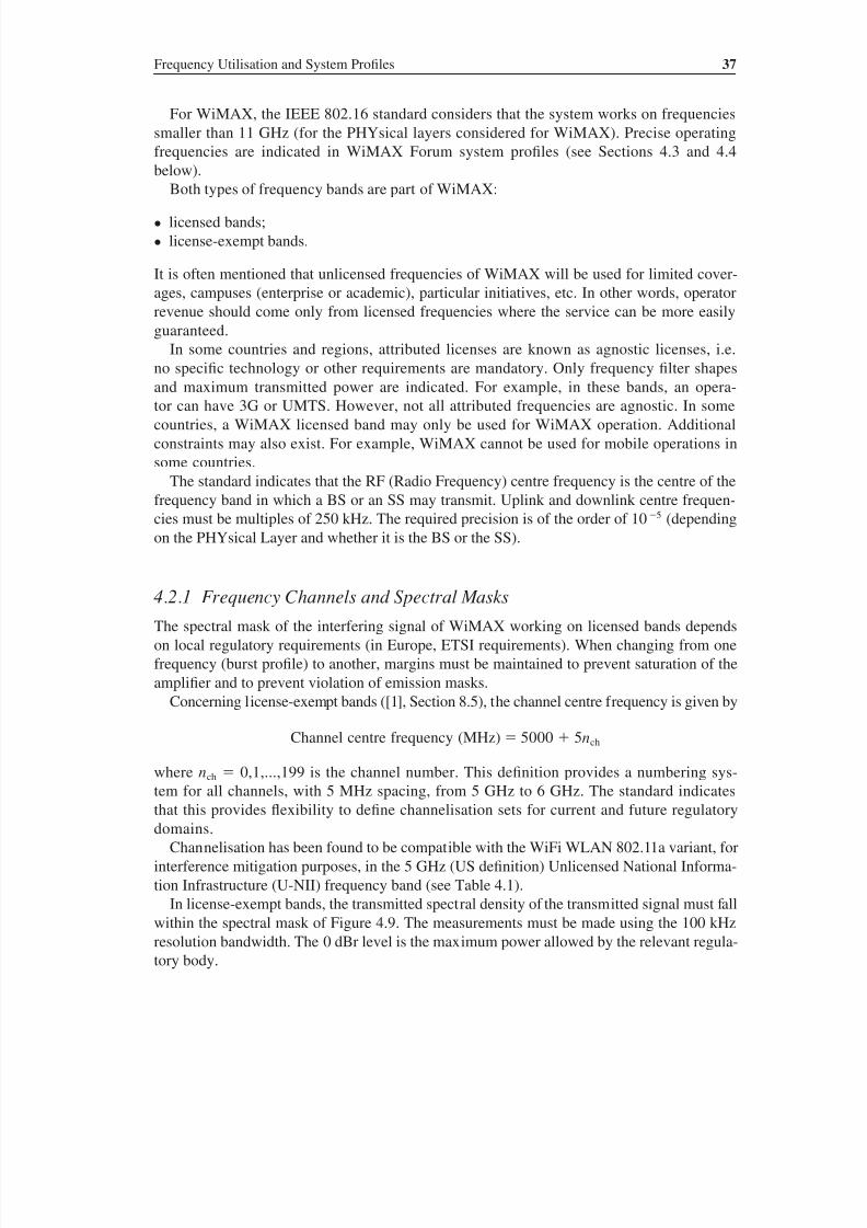
8/10/2019 WiMax-Tech for BBW Access
http://slidepdf.com/reader/full/wimax-tech-for-bbw-access 57/293
Frequency Utilisation and System Profiles 37
For WiMAX, the IEEE 802.16 standard considers that the system works on frequencies
smaller than 11 GHz (for the PHYsical layers considered for WiMAX). Precise operating
frequencies are indicated in WiMAX Forum system profiles (see Sections 4.3 and 4.4
below).
Both types of frequency bands are part of WiMAX:
• licensed bands;
• license-exempt bands.
It is often mentioned that unlicensed frequencies of WiMAX will be used for limited cover-
ages, campuses (enterprise or academic), particular initiatives, etc. In other words, operator
revenue should come only from licensed frequencies where the service can be more easily
guaranteed.
In some countries and regions, attributed licenses are known as agnostic licenses, i.e.
no specific technology or other requirements are mandatory. Only frequency filter shapesand maximum transmitted power are indicated. For example, in these bands, an opera-
tor can have 3G or UMTS. However, not all attributed frequencies are agnostic. In some
countries, a WiMAX licensed band may only be used for WiMAX operation. Additional
constraints may also exist. For example, WiMAX cannot be used for mobile operations in
some countries.
The standard indicates that the RF (Radio Frequency) centre frequency is the centre of the
frequency band in which a BS or an SS may transmit. Uplink and downlink centre frequen-
cies must be multiples of 250 kHz. The required precision is of the order of 10 5 (depending
on the PHYsical Layer and whether it is the BS or the SS).
4.2.1 Frequency Channels and Spectral Masks
The spectral mask of the interfering signal of WiMAX working on licensed bands depends
on local regulatory requirements (in Europe, ETSI requirements). When changing from one
frequency (burst profile) to another, margins must be maintained to prevent saturation of the
amplifier and to prevent violation of emission masks.
Concerning license-exempt bands ([1], Section 8.5), the channel centre frequency is given by
Channel centre frequency (MHz) 5000 5nch
where nch 0,1,...,199 is the channel number. This definition provides a numbering sys-
tem for all channels, with 5 MHz spacing, from 5 GHz to 6 GHz. The standard indicates
that this provides flexibility to define channelisation sets for current and future regulatory
domains.
Channelisation has been found to be compatible with the WiFi WLAN 802.11a variant, for
interference mitigation purposes, in the 5 GHz (US definition) Unlicensed National Informa-
tion Infrastructure (U-NII) frequency band (see Table 4.1).
In license-exempt bands, the transmitted spectral density of the transmitted signal must fall
within the spectral mask of Figure 4.9. The measurements must be made using the 100 kHz
resolution bandwidth. The 0 dBr level is the maximum power allowed by the relevant regula-
tory body.

8/10/2019 WiMax-Tech for BBW Access
http://slidepdf.com/reader/full/wimax-tech-for-bbw-access 58/293

8/10/2019 WiMax-Tech for BBW Access
http://slidepdf.com/reader/full/wimax-tech-for-bbw-access 59/293
Frequency Utilisation and System Profiles 39
widely announced WiMAX frequency band. We here mention that third-generation (3G)
cellular systems operating in the 2.5 GHz band as an extension band for these systems have
been reported.
• License-exempt bands: 5 GHz. The 2004 WiMAX unlicensed frequency fixed profile used
the upper U-NII frequency band, i.e. the 5.8 GHz frequency band (see Table 4.1). In the
future, various bands between 5 GHz and 6 GHz can be used for unlicensed WiMAX,depending on the country involved.
Table 4.3 shows (globally) the present expected WiMAX frequencies around the world. Other
frequencies are sought. These frequencies should not be higher than the 5.8 GHz already cho-
sen because, for relatively high frequencies (3.5 GHz is itself not a very small value), NLOS
operation becomes difficult, which is an evident problem for mobility. The Regulatory Work-
ing Group (RWG), introduced in Chapter 2, is trying to define both new frequencies (reports
talk about 450 MHz and 700 MHz) and also the conditions for an easy universal roaming
with (possible) different frequencies in different countries. Regulator requirements mainly
allow both Time Division Duplexing (TDD) and Frequency Division Duplexing (FDD). Theattributed frequency spectrum size is a function of the country. Some elements about the
WiMAX situation in some countries are given below.
4.3.1 France
In France, as elsewhere, the authorities wish to have (at least fixed) broadband access in the
highest possible percentage of the territory. WiMAX has been seen as a means to provide this
broadband access. Altitude Operator (owned by Iliad) has a WiMAX license in the 3.5 GHz
band. Altitude obtained it in 2003 when the regulating authority, Autorité de Régulation des
Télécommunication (ART), accepted that Altitude takes a WLL license owned (and not used)by another operator. Since then, ART has changed its name to become ARCEP (Autorité de
Régulation des Communications Electroniques et des Postes, http://www.arcep.fr).
Table 4.2 Transmit spectral mask parameters [1]. A, B,
C and D are in MHz
Channelisation
(MHz) A B C D
20 9.5 10.9 19.5 29.5
10 4.75 5.45 9.75 14.75
Table 4.3 Expected WiMAX frequencies (based on RWG documents)
Region or country Reported WiMAX frequency bands
USA 2.3, 2.5 and 5.8 GHz
Central and South America 2.5, 3.5 and 5.8 GHz
Europe 3.5 and 5.8 GHz; possible: 2.5 GHz
South-East Asia 2.3, 2.5, 3.3, 3.5 and 5.8 GHzMiddle East and Africa 3.5 and 5.8 GHz
8/10/2019 WiMax-Tech for BBW Access
http://slidepdf.com/reader/full/wimax-tech-for-bbw-access 60/293
40 WiMAX: Technology for Broadband Wireless Access
In August 2005, ARCEP started the process of attribution of two other WiMAX licenses
(215 MHz each):
• BLR 1: 3465–3480 and 3565–3580 MHz;
• BLR 2: 3432.5–3447.5 and 3532.5–3547.5 MHz.
This process ended in July 2006 by the allocation of these two licences to two operators in
each of the 22 French metropolitan regions. However, Altitude is the only French operator
with a national WiMAX license. The choice was made based on three equally important
criteria:
• contribution to the territorial development of broadband access;
• aptitude to ameliorate a high data rate concurrence;
• allowances paid by the operator.
The operators should have a minimum number (in total) of 3500 WiMAX sites by June 2008.They will be paying 125 million euros in 2006.
4.3.2 Korea
In Korea, the frequencies attributed to WiBro are in the 2.3–2.4 GHz band. In 2002, 100 MHz
bands were decided for WiBro in Korea and WiBro licenses were attributed in January 2005.
The three operators are Korea Telecom (KT), SK Telecom (SKT) and Hanaro Telecom. Pilot
networks are already in place (April 2006). Relatively broad coverage public commercial
offers should start before the end of 2006.
4.3.3 USA
In the USA, a large number of 2.5 GHz band licenses (the BRS, or Broadband Radio Service,
and the EBS, or Educational Broadband Service) and 2.3 GHz band licenses (WCS, or Wire-
less Communications Service) are owned by many operators. Sprint and Nextel have joined
forces, providing them with by far the greatest number of population served by their license.
In the USA, until now the 2.5 GHz band had often been attributed for the MMDS. However,
EBS licenses have been given to educational entities so that they can be used for educational
purposes and the Federal Communications Commission (FCC) has allowed EBS license
holders to lease spectra to commercial entities under certain conditions.
4.3.4 UK
Currently, two operators have BWA licenses in the UK: PCCW (UK Broadband) and Pipex.
Their licenses are in the 3.4 GHz (PCCW) and 3.5 GHz (Pipex) bands. A number of smaller
operators use or plan to use a license-exempt WiMAX frequency band for limited operations.
4.3.5 China
China is a country with big dimensions and a still developing telecommunications network.
For the moment (October 2006), no license for commercial service of WiMAX has been
allocated. However, WiMAX trials are taking place in many regions and are regularly
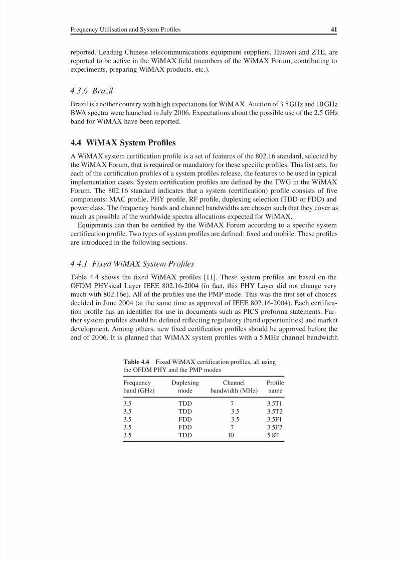
8/10/2019 WiMax-Tech for BBW Access
http://slidepdf.com/reader/full/wimax-tech-for-bbw-access 61/293
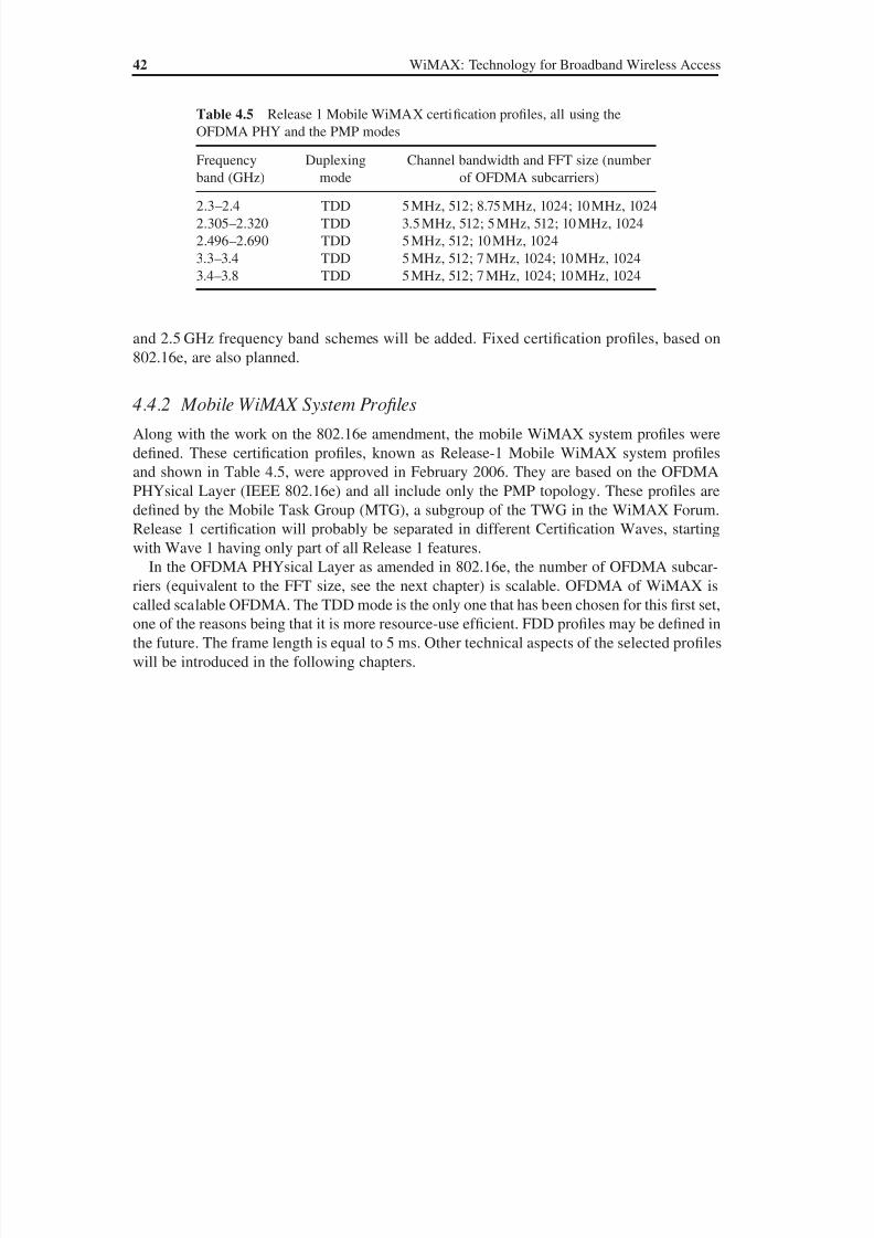
8/10/2019 WiMax-Tech for BBW Access
http://slidepdf.com/reader/full/wimax-tech-for-bbw-access 62/293
42 WiMAX: Technology for Broadband Wireless Access
and 2.5 GHz frequency band schemes will be added. Fixed certification profiles, based on
802.16e, are also planned.
4.4.2 Mobile WiMAX System Profiles
Along with the work on the 802.16e amendment, the mobile WiMAX system profiles were
defined. These certification profiles, known as Release-1 Mobile WiMAX system profiles
and shown in Table 4.5, were approved in February 2006. They are based on the OFDMA
PHYsical Layer (IEEE 802.16e) and all include only the PMP topology. These profiles are
defined by the Mobile Task Group (MTG), a subgroup of the TWG in the WiMAX Forum.
Release 1 certification will probably be separated in different Certification Waves, starting
with Wave 1 having only part of all Release 1 features.
In the OFDMA PHYsical Layer as amended in 802.16e, the number of OFDMA subcar-riers (equivalent to the FFT size, see the next chapter) is scalable. OFDMA of WiMAX is
called scalable OFDMA. The TDD mode is the only one that has been chosen for this first set,
one of the reasons being that it is more resource-use efficient. FDD profiles may be defined in
the future. The frame length is equal to 5 ms. Other technical aspects of the selected profiles
will be introduced in the following chapters.
Table 4.5 Release 1 Mobile WiMAX certification profiles, all using the
OFDMA PHY and the PMP modes
Frequency
band (GHz)
Duplexing
mode
Channel bandwidth and FFT size (number
of OFDMA subcarriers)
2.3–2.4 TDD 5 MHz, 512; 8.75 MHz, 1024; 10 MHz, 1024
2.305–2.320 TDD 3.5 MHz, 512; 5 MHz, 512; 10 MHz, 1024
2.496–2.690 TDD 5 MHz, 512; 10 MHz, 1024
3.3–3.4 TDD 5 MHz, 512; 7 MHz, 1024; 10 MHz, 1024
3.4–3.8 TDD 5 MHz, 512; 7 MHz, 1024; 10 MHz, 1024

8/10/2019 WiMax-Tech for BBW Access
http://slidepdf.com/reader/full/wimax-tech-for-bbw-access 63/293
8/10/2019 WiMax-Tech for BBW Access
http://slidepdf.com/reader/full/wimax-tech-for-bbw-access 64/293
5Digital Modulation, OFDMand OFDMA
5.1 Digital Modulations
As for all recent communication systems, WiMAX/802.16 uses digital modulation. The now
well-known principle of a digital modulation is to modulate an analogue signal with a digital
sequence in order to transport this digital sequence over a given medium: fibre, radio link,
etc. (see Figure 5.1). This has great advantages with regard to classical analogue modulation:
better resistance to noise, use of high-performance digital communication and coding algo-
rithms, etc.
Many digital modulations can be used in a telecommunication system. The variants are
obtained by adjusting the physical characteristics of a sinusoidal carrier, either the frequency,
phase or amplitude, or a combination of some of these. Four modulations are supported by the
IEEE 802.16 standard: BPSK, QPSK, 16-QAM and 64-QAM. In this section the modulations
used in the OFDM and OFDMA PHYsical layers are introduced with a short explanation for
each of these modulations.
5.1.1 Binary Phase Shift Keying (BPSK)
The BPSK is a binary digital modulation; i.e. one modulation symbol is one bit. This gives
high immunity against noise and interference and a very robust modulation. A digital phase
modulation, which is the case for BPSK modulation, uses phase variation to encode bits: eachmodulation symbol is equivalent to one phase. The phase of the BPSK modulated signal is π
or π according to the value of the data bit. An often used illustration for digital modulation
is the constellation. Figure 5.2 shows the BPSK constellation; the values that the signal phase
can take are 0 or π.
5.1.2 Quadrature Phase Shift Keying (QPSK)
When a higher spectral efficiency modulation is needed, i.e. more b/s/Hz, greater modu-
lation symbols can be used. For example, QPSK considers two-bit modulation symbols.
WiMAX: Technology for Broadband Wireless Access Loutfi Nuaymi
© 2007 John Wiley & Sons, Ltd. ISBN: 0-470-02808-4
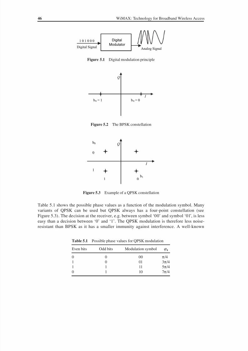
8/10/2019 WiMax-Tech for BBW Access
http://slidepdf.com/reader/full/wimax-tech-for-bbw-access 65/293
46 WiMAX: Technology for Broadband Wireless Access
Table 5.1 shows the possible phase values as a function of the modulation symbol. Many
variants of QPSK can be used but QPSK always has a four-point constellation (see
Figure 5.3). The decision at the receiver, e.g. between symbol ‘00’ and symbol ‘01’, is less
easy than a decision between ‘0’ and ‘1’. The QPSK modulation is therefore less noise-
resistant than BPSK as it has a smaller immunity against interference. A well-known
Digital
ModulatorDigital Signal
1 0 1 0 0 0
Analog Signal
Figure 5.1 Digital modulation principle
Q
I b0 b= 1 0 = 0
Figure 5.2 The BPSK constellation
Table 5.1 Possible phase values for QPSK modulation
Even bits Odd bits Modulation symbol {k
0 0 00 π /4
1 0 01 3π /4
1 1 11 5π /40 1 10 7π /4
Q
I
b0
b1
0
1
1 0
Figure 5.3 Example of a QPSK constellation
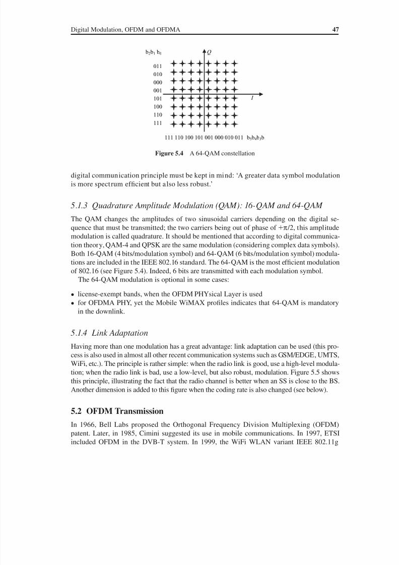
8/10/2019 WiMax-Tech for BBW Access
http://slidepdf.com/reader/full/wimax-tech-for-bbw-access 66/293
Digital Modulation, OFDM and OFDMA 47
digital communication principle must be kept in mind: ‘A greater data symbol modulation
is more spectrum efficient but also less robust.’
5.1.3 Quadrature Amplitude Modulation (QAM): 16-QAM and 64-QAM
The QAM changes the amplitudes of two sinusoidal carriers depending on the digital se-
quence that must be transmitted; the two carriers being out of phase of π /2, this amplitude
modulation is called quadrature. It should be mentioned that according to digital communica-
tion theory, QAM-4 and QPSK are the same modulation (considering complex data symbols).
Both 16-QAM (4 bits/modulation symbol) and 64-QAM (6 bits/modulation symbol) modula-
tions are included in the IEEE 802.16 standard. The 64-QAM is the most efficient modulation
of 802.16 (see Figure 5.4). Indeed, 6 bits are transmitted with each modulation symbol.
The 64-QAM modulation is optional in some cases:
• license-exempt bands, when the OFDM PHYsical Layer is used
• for OFDMA PHY, yet the Mobile WiMAX profiles indicates that 64-QAM is mandatory
in the downlink.
5.1.4 Link Adaptation
Having more than one modulation has a great advantage: link adaptation can be used (this pro-
cess is also used in almost all other recent communication systems such as GSM/EDGE, UMTS,
WiFi, etc.). The principle is rather simple: when the radio link is good, use a high-level modula-
tion; when the radio link is bad, use a low-level, but also robust, modulation. Figure 5.5 shows
this principle, illustrating the fact that the radio channel is better when an SS is close to the BS.
Another dimension is added to this figure when the coding rate is also changed (see below).
5.2 OFDM Transmission
In 1966, Bell Labs proposed the Orthogonal Frequency Division Multiplexing (OFDM)
patent. Later, in 1985, Cimini suggested its use in mobile communications. In 1997, ETSI
included OFDM in the DVB-T system. In 1999, the WiFi WLAN variant IEEE 802.11g
Q
I
b2 b1 b0
b5 b4 b3 b
011
010
000
001
101
100
110
111
111 110 100 101 001 000 010 011
Figure 5.4 A 64-QAM constellation
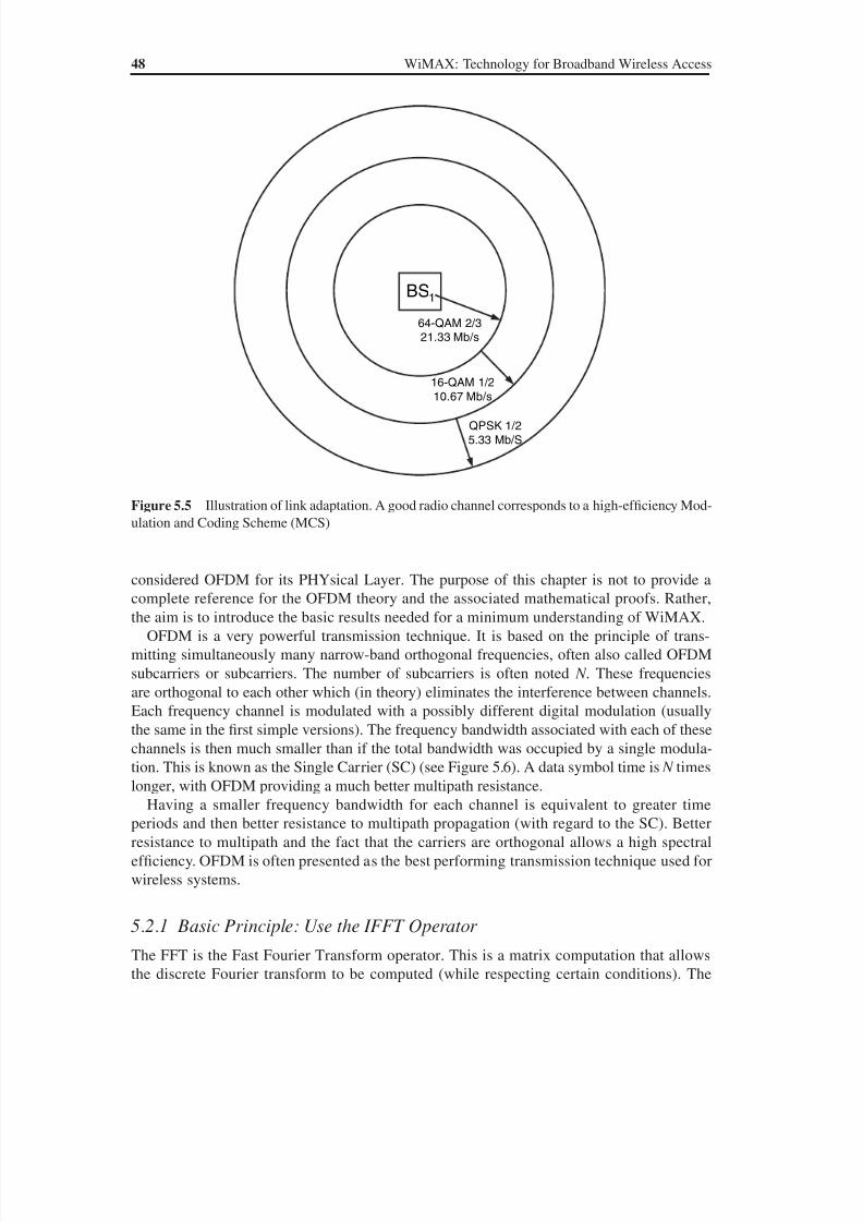
8/10/2019 WiMax-Tech for BBW Access
http://slidepdf.com/reader/full/wimax-tech-for-bbw-access 67/293
48 WiMAX: Technology for Broadband Wireless Access
considered OFDM for its PHYsical Layer. The purpose of this chapter is not to provide a
complete reference for the OFDM theory and the associated mathematical proofs. Rather,
the aim is to introduce the basic results needed for a minimum understanding of WiMAX.
OFDM is a very powerful transmission technique. It is based on the principle of trans-
mitting simultaneously many narrow-band orthogonal frequencies, often also called OFDM
subcarriers or subcarriers. The number of subcarriers is often noted N . These frequencies
are orthogonal to each other which (in theory) eliminates the interference between channels.
Each frequency channel is modulated with a possibly different digital modulation (usually
the same in the first simple versions). The frequency bandwidth associated with each of these
channels is then much smaller than if the total bandwidth was occupied by a single modula-
tion. This is known as the Single Carrier (SC) (see Figure 5.6). A data symbol time is N times
longer, with OFDM providing a much better multipath resistance.
Having a smaller frequency bandwidth for each channel is equivalent to greater time
periods and then better resistance to multipath propagation (with regard to the SC). Better
resistance to multipath and the fact that the carriers are orthogonal allows a high spectral
efficiency. OFDM is often presented as the best performing transmission technique used for
wireless systems.
5.2.1 Basic Principle: Use the IFFT Operator The FFT is the Fast Fourier Transform operator. This is a matrix computation that allows
the discrete Fourier transform to be computed (while respecting certain conditions). The
QPSK 1/2
5.33 Mb/S
16-QAM 1/2
10.67 Mb/s
64-QAM 2/3
21.33 Mb/s
BS1
Figure 5.5 Illustration of link adaptation. A good radio channel corresponds to a high-efficiency Mod-
ulation and Coding Scheme (MCS)

8/10/2019 WiMax-Tech for BBW Access
http://slidepdf.com/reader/full/wimax-tech-for-bbw-access 68/293
Digital Modulation, OFDM and OFDMA 49
FFT works for any number of points. The operation is simpler when applied for a number
N which is a power of 2 (e.g. N 256). The IFFT is the Inverse Fast Fourier Transform op-
erator and realises the reverse operation. OFDM theory (see, for example, Reference [12])shows that the IFFT of magnitude N , applied on N symbols, realises an OFDM signal, where
each symbol is transmitted on one of the N orthogonal frequencies. The symbols are the
data symbols of the type BPSK, QPSK, QAM-16 and QAM-64 introduced in the previous
section. Figure 5.7 shows an illustration of the simplified principle of the generation of an
OFDM signal. In fact, generation of this signal includes more details that are not shown here
for the sake of simplicity.
Data Symbols
Time
SC(Single
Carrier)
Frequency Spectrum
Frequency
Data Symbols
Time
OFDM
Frequency
Frequency Spectrum:N orthogonal Subcarriers
Figure 5.6 Time and frequency representation of the SC and OFDM. In OFDM, N data symbols are
transmitted simultaneously on N orthogonal subcarriers
[X0 ,X1 ,….,X N -1 ] OFDM Signal
T d X0
X N -1
X1
T d
Serial/
Parallel
Conversion
IFFT
Each (modulation) symbol is
modulated with a possiblydifferent modulation
Figure 5.7 Generation of an OFDM signal (simplified)
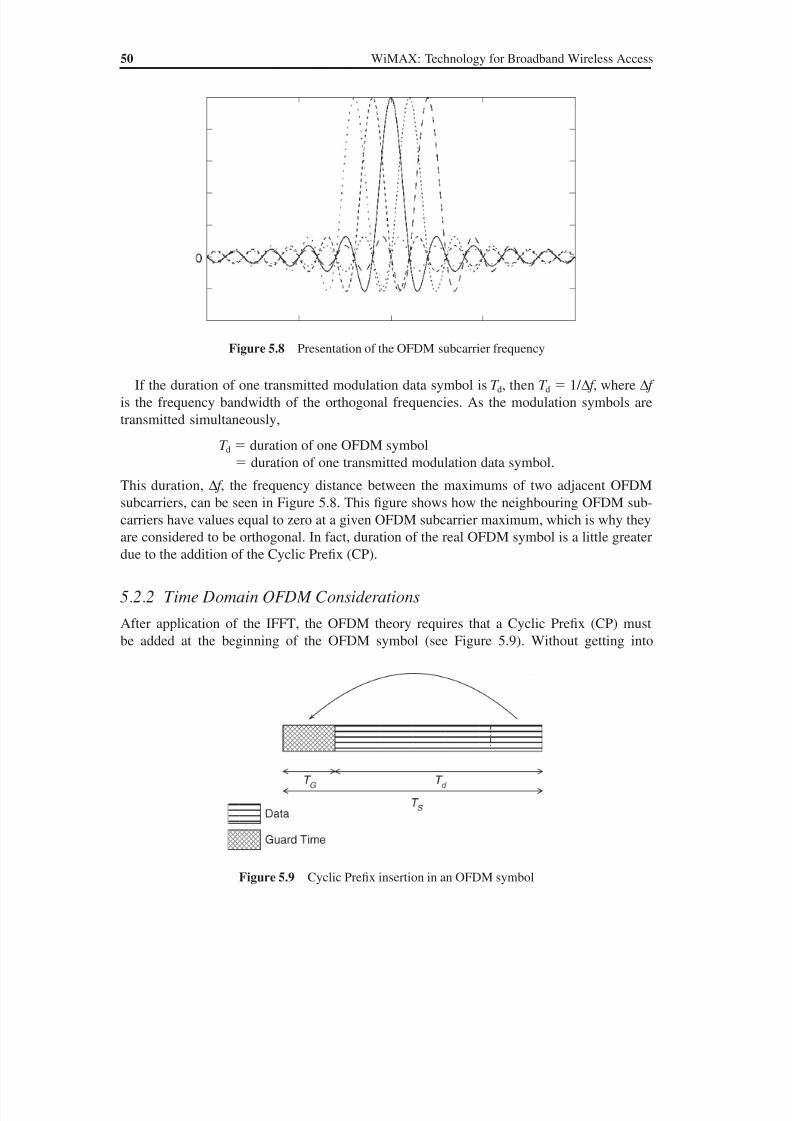
8/10/2019 WiMax-Tech for BBW Access
http://slidepdf.com/reader/full/wimax-tech-for-bbw-access 69/293
50 WiMAX: Technology for Broadband Wireless Access
If the duration of one transmitted modulation data symbol is T d, then T d 1/ ∆ f , where ∆ f
is the frequency bandwidth of the orthogonal frequencies. As the modulation symbols are
transmitted simultaneously,
T d duration of one OFDM symbol
duration of one transmitted modulation data symbol.
This duration, ∆ f , the frequency distance between the maximums of two adjacent OFDM
subcarriers, can be seen in Figure 5.8. This figure shows how the neighbouring OFDM sub-
carriers have values equal to zero at a given OFDM subcarrier maximum, which is why they
are considered to be orthogonal. In fact, duration of the real OFDM symbol is a little greater
due to the addition of the Cyclic Prefix (CP).
5.2.2 Time Domain OFDM Considerations
After application of the IFFT, the OFDM theory requires that a Cyclic Prefix (CP) must
be added at the beginning of the OFDM symbol (see Figure 5.9). Without getting into
Figure 5.8 Presentation of the OFDM subcarrier frequency
Figure 5.9 Cyclic Prefix insertion in an OFDM symbol

8/10/2019 WiMax-Tech for BBW Access
http://slidepdf.com/reader/full/wimax-tech-for-bbw-access 70/293
Digital Modulation, OFDM and OFDMA 51
mathematical details of OFDM, it can be said that the CP allows the receiver to absorb much
more efficiently the delay spread due to the multipath and to maintain frequency orthogonal-
ity. The CP that occupies a duration called the Guard Time (GT), often denoted T G, is a tem-
poral redundancy that must be taken into account in data rate computations. The ratio T G / T d
is very often denoted G in WiMAX/802.16 documents. The choice of G is made accordingto the following considerations: if the multipath effect is important (a bad radio channel), a
high value of G is needed, which increases the redundancy and then decreases the useful data
rate; if the multipath effect is lighter (a good radio channel), a relatively smaller value of G
can be used. For OFDM and OFDMA PHY layers, 802.16 defined the following values for G:
1/4, 1/8, 1/16 and 1/32. For the mobile (OFDMA) WiMAX profiles presently defined, only
the value 1/8 is mandatory. The standard indicates that, for OFDM and OFDMA PHY layers,
an SS searches, on initialization, for all possible values of the CP until it finds the CP being
used by the BS. The SS then uses the same CP on the uplink. Once a specific CP duration has
been selected by the BS for operation on the downlink, it cannot be changed. Changing the
CP would force all the SSs to resynchronize to the BS [1].
5.2.3 Frequency Domain OFDM Considerations
All the subcarriers of an OFDM symbol do not carry useful data. There are four subcarrier
types (see Figure 5.10):
• Data subcarriers: useful data transmission.
• Pilot subcarriers: mainly for channel estimation and synchronisation. For OFDM PHY,
there are eight pilot subcarriers.
• Null subcarriers: no transmission. These are frequency guard bands.• Another null subcarrier is the DC (Direct Current) subcarrier. In OFDM and OFDMA
PHY layers, the DC subcarrier is the subcarrier whose frequency is equal to the RF centre
frequency of the transmitting station. It corresponds to frequency zero (Direct Current) if
the FFT signal is not modulated. In order to simplify Digital-to-Analogue and Analogue-
to-Digital Converter operations, the DC subcarrier is null.
In addition, subcarriers used for PAPR reduction (see below), if present, are not used for data
transmission.
Left guardsubcarriers
Right guardsubcarriers
DC
N used
Data subcarriersPilot subcarriers
Figure 5.10 WiMAX OFDM subcarriers types. (Based on Reference [10].)
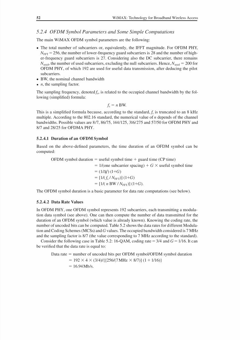
8/10/2019 WiMax-Tech for BBW Access
http://slidepdf.com/reader/full/wimax-tech-for-bbw-access 71/293
52 WiMAX: Technology for Broadband Wireless Access
5.2.4 OFDM Symbol Parameters and Some Simple Computations
The main WiMAX OFDM symbol parameters are the following:
• The total number of subcarriers or, equivalently, the IFFT magnitude. For OFDM PHY,
N FFT 256, the number of lower-frequency guard subcarriers is 28 and the number of high-er-frequency guard subcarriers is 27. Considering also the DC subcarrier, there remains
N used, the number of used subcarriers, excluding the null subcarriers. Hence, N used 200 for
OFDM PHY, of which 192 are used for useful data transmission, after deducing the pilot
subcarriers.
• BW, the nominal channel bandwidth
• n, the sampling factor.
The sampling frequency, denoted f s, is related to the occupied channel bandwidth by the fol-
lowing (simplified) formula:
f s n BW.
This is a simplified formula because, according to the standard, f s is truncated to an 8 kHz
multiple. According to the 802.16 standard, the numerical value of n depends of the channel
bandwidths. Possible values are 8/7, 86/75, 144/125, 316/275 and 57/50 for OFDM PHY and
8/7 and 28/25 for OFDMA PHY.
5.2.4.1 Duration of an OFDM Symbol
Based on the above-defined parameters, the time duration of an OFDM symbol can be
computed:
OFDM symbol duration useful symbol time guard time (CP time)
1/(one subcarrier spacing) G useful symbol time
(1/ ∆ f ) (1G)
[1/( f s / N FFT)] (1G)
[1/( n BW / N FFT)] (1G).
The OFDM symbol duration is a basic parameter for data rate computations (see below).
5.2.4.2 Data Rate Values
In OFDM PHY, one OFDM symbol represents 192 subcarriers, each transmitting a modula-
tion data symbol (see above). One can then compute the number of data transmitted for the
duration of an OFDM symbol (which value is already known). Knowing the coding rate, the
number of uncoded bits can be computed. Table 5.2 shows the data rates for different Modula-
tion and Coding Schemes (MCSs) and G values. The occupied bandwidth considered is 7 MHz
and the sampling factor is 8/7 (the value corresponding to 7 MHz according to the standard).
Consider the following case in Table 5.2: 16-QAM, coding rate 3/4 and G 1/16. It can
be verified that the data rate is equal to:
Data rate number of uncoded bits per OFDM symbol/OFDM symbol duration
192 4 (3/4)/{[256/(7 MHz 8/7)] (11/16)}
16.94 Mb/s.

8/10/2019 WiMax-Tech for BBW Access
http://slidepdf.com/reader/full/wimax-tech-for-bbw-access 72/293
Digital Modulation, OFDM and OFDMA 53
It should be noted here that these data rate values do not take into account some overheads
such as preambles (of the order of one or two OFDM symbols per frame) and signalling mes-
sages present in every frame (see Chapter 9 and others in this book). Hence these data rates,
known as raw data rates, are optimistic values.
5.2.5 Physical Slot (PS)
The Physical Slot (PS) is a basic unit of time in the 802.16 standard. The PS corresponds to
four (modulation) symbols used on the transmission channel. For OFDM and OFDMA PHY
Layers, a PS (duration) is defined as [1]
PS 4/ f s.
Therefore the PS duration is related to the system symbol rate.
This unit of time defined in the standard allows integers to be used while referring to an
amount of time, e.g. the definition of transition gaps (RTG and TTG) between uplink and
downlink frames in the TDD mode.
5.2.6 Peak-to-Average Power Ratio (PAPR)
A disadvantage of an OFDM transmission is that it can have a high Peak-to-Average Power
Ratio (PAPR), relative to a single carrier transmission. The PAPR is the peak value of trans-
mitted subcarriers to the average transmitted signal. A high PAPR represents a hard con-
straint for some devices (such as amplifiers). Several solutions are proposed for OFDM PAPR
reduction, often including the use of some subcarriers for that purpose. These subcarriers arethen no longer used for data transmission. The 802.16 MAC provides the means to reduce the
PAPR. PAPR reduction sequences are proposed in Reference [2].
5.3 OFDMA and Its Variant SOFDMA
5.3.1 Using the OFDM Principle for Multiple Access
The OFDM transmission mode was originally designed for a single signal transmission.
Thus, in order to have multiple user transmissions, a multiple access scheme such as TDMA
or FDMA has to be associated with OFDM. In fact, an OFDM signal can be made from many
user signals, giving the OFDMA (Orthogonal Frequency Division Multiple Access) multiple
access.
Table 5.2 OFDM PHY data rates in Mb/s. (From IEEE Std 802.16-2004 [1]. Copyright
IEEE 2004, IEEE. All rights reserved.)
G ratio BPSK
1/2
QPSK
1/2
QPSK
3/4
16-QAM
1/2
16-QAM
3/4
64-QAM
2/3
64-QAM
3/4
1/32 2.92 5.82 8.73 11.64 17.45 23.27 26.18
1/16 2.82 5.65 8.47 11.29 16.94 22.59 25.41
1/8 2.67 5.33 8.00 10.67 16.00 21.33 24.00
1/4 2.40 4.80 7.20 9.60 14.40 19.20 21.60

8/10/2019 WiMax-Tech for BBW Access
http://slidepdf.com/reader/full/wimax-tech-for-bbw-access 73/293
54 WiMAX: Technology for Broadband Wireless Access
In OFDMA, the OFDMA subcarriers are divided into subsets of subcarriers, each subset
representing a subchannel (see Figure 5.11). In the downlink, a subchannel may be intended
for different receivers or groups of receivers; in the uplink, a transmitter may be assigned one
or more subchannels. The subcarriers forming one subchannel may be adjacent or not. The
standard [1] indicates that the OFDM symbol is divided into logical subchannels to support
scalability, multiple access and advanced antenna array processing capabilities. The multiple
access has a new dimension with OFDMA. A downlink or an uplink user will have a time and
a subchannel allocation for each of its communications (see Figure 5.12). Different subchannel
Figure 5.11 Illustration of the OFDMA principle. (Based on Reference [1].)
Left guardsubcarriers
Right guardsubcarriers
DC
N used
Data subcarriers
subchannel 1
subchannel 2
subchannel 3
subchannel 4
S u b c h a n n e l s ( s e t
o f s u b c a r r i e r s )
TimeOFDMSymbol n
OFDMSymbol n +1
OFDMSymbol n + 2
OFDMSymbol n + 3
User 1
User 2
User 3
User 4
User 5
Figure 5.12 Illustration of OFDMA multiple access

8/10/2019 WiMax-Tech for BBW Access
http://slidepdf.com/reader/full/wimax-tech-for-bbw-access 74/293
Digital Modulation, OFDM and OFDMA 55
distributions and logical renumberings are defined in the 802.16 standard, as will be seen in
the rest of this chapter. First, the SOFDMA concept is introduced.
5.3.2 Scalable OFDMA (SOFDMA)
OFDMA multiple access is not the only specificity of OFDMA PHY. Another major differ-
ence is the fact that its OFDM transmission is scalable. Although this word does not appear in
the standard, OFDMA PHY is said to have Scalable OFDMA (SOFDMA). The scalability is
the change of the FFT size and then the number of subcarriers. The supported FFT sizes are
2048, 1024, 512 and 128. FFT size 256 (of the OFDM layer) is not included in the OFDMA
layer. Only 1024 and 512 are mandatory for mobile WiMAX profiles.
The change in the number of subcarriers, for a fixed subcarrier spacing, provides for an
adaptive occupied frequency bandwidth and, equivalently, an adaptive data rate, as shown
in the following example. See the example shown in Table 5.3. In this example, the sam-
pling factor is equal to 28/25, chosen according to the channel bandwidth. SOFDMA pro-
vides an additional resource allocation flexibility that can be used in the framework of radio
resource management policy taking into account the dynamic spectrum demand, among
others.
5.3.3 OFDMA in the OFDM PHYsical Layer: Subchannelisation
As a matter of fact, the OFDM PHY includes some OFDMA access. Subchannelisation was
included in 802.16-2004 for the uplink and also for the downlink in amendment 802.16e. The
principle is the following. The 192 useful data OFDM subcarriers of OFDM PHY are distrib-
uted in 16 subchannels made of 12 subcarriers each. Each subchannel is made of four groups
of three adjacent subchannels each (see below).
A subchannelised transmission is a transmission on only part of the OFDM subcarrier
space. The subchannelised transmission can take place on 1, 2, 4, 8 or 16 subchannels. A
five-bit indexation shown in Table 5.4 indicates the number of subchannels and the subcarrier
indices used for each subchannel index for the uplink. As shown in this table, one or more
pilot subcarrier(s) (there are eight in total) are allocated only if two or more subchannels
are allocated. The subcarriers other than the ones used for subchannelised transmission are
nonactive (for the transmitter). The five-bit subchannel index is used in the uplink allocation
message UL-MAP (see Chapter 9 for the UL-MAP).
Table 5.3 Example of SOFDMA figures. (Inspired from Reference [10].)
Parameters Numerical values
Subcarrier frequency spacing 10.95 kHz
Useful symbol duration (T d 1/ ∆ f ) 91.4µsGuard time (T G T d /8) 11.4µs
OFDMA symbol duration (T s T d T G) 102.9µs
Number of OFDMA symbols in the 5 ms frame 48
FFT size ( N FFT) or number of subcarriers 512 1024
Channel occupied bandwidth 5 MHz 10 MHz
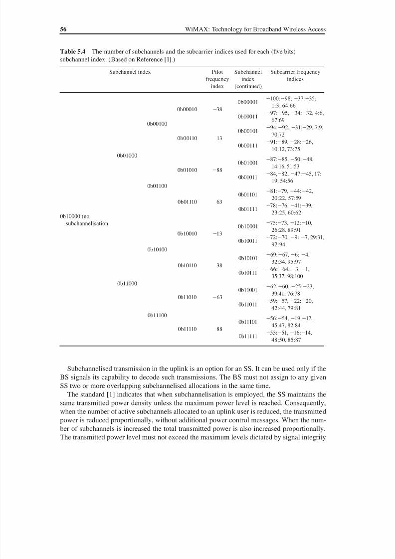
8/10/2019 WiMax-Tech for BBW Access
http://slidepdf.com/reader/full/wimax-tech-for-bbw-access 75/293
56 WiMAX: Technology for Broadband Wireless Access
Subchannelised transmission in the uplink is an option for an SS. It can be used only if the
BS signals its capability to decode such transmissions. The BS must not assign to any given
SS two or more overlapping subchannelised allocations in the same time.
The standard [1] indicates that when subchannelisation is employed, the SS maintains the
same transmitted power density unless the maximum power level is reached. Consequently,
when the number of active subchannels allocated to an uplink user is reduced, the transmitted
power is reduced proportionally, without additional power control messages. When the num-
ber of subchannels is increased the total transmitted power is also increased proportionally.
The transmitted power level must not exceed the maximum levels dictated by signal integrity
Table 5.4 The number of subchannels and the subcarrier indices used for each (five bits)
subchannel index. (Based on Reference [1].)
Subchannel index Pilot
frequency
index
Subchannel
index
(continued)
Subcarrier frequency
indices
0b10000 (no
subchannelisation
0b01000
0b00100
0b00010 38
0b00001100:98; 37:35;
1:3; 64:66
0b0001197:95,34:32, 4:6,
67:69
0b00110 13
0b0010194:92, 31:29, 7:9,
70:72
0b0011191:89,28:26,
10:12, 73:75
0b01100
0b01010 88
0b0100187:85, 50:48,
14:16, 51:53
0b0101184,82, 47:45, 17:
19, 54:56
0b01110 63
0b0110181:79,44:42,
20:22, 57:59
0b0111178:76,41:39,
23:25, 60:62
0b11000
0b10100
0b10010 13
0b1000175:73, 12:10,
26:28, 89:91
0b1001172:70,9: 7, 29:31,
92:94
0b10110 38
0b10101 69:67,6: 4,32:34, 95:97
0b1011166:64, 3: 1,
35:37, 98:100
0b11100
0b11010 63
0b1100162:60, 25:23,
39:41, 76:78
0b1101159:57,22:20,
42:44, 79:81
0b11110 88
0b1110156:54, 19:17,
45:47, 82:84
0b1111153:51,16:14,
48:50, 85:87
8/10/2019 WiMax-Tech for BBW Access
http://slidepdf.com/reader/full/wimax-tech-for-bbw-access 76/293
Digital Modulation, OFDM and OFDMA 57
considerations and regulatory requirements. The subchannelisation can then represent trans-
mitted power decreases and, equivalently, capacity gains.
The 802.16e amendment defined an optional downlink subchannelisation zone in the
OFDM PHY downlink subframe. Uplink subchannels are partly reused.
5.4 Subcarrier Permutations in WiMAX OFDMA PHY
Distributing the subcarriers over the subchannels is a very open problem with many param-
eters to consider: mobility, AAS support, different optimisation criterions, etc. The 802.16
standard and its amendment 802.16e provide full details for the many subcarriers permuta-
tions defined. In this section, we briefly describe the subcarriers permutations defined in
Mobile WiMAX OFDMA PHY and detail one of these permutations.
5.4.1 The Main Permutation Modes in OFDMASubtracting the guard subcarriers and the DC subcarrier from N FFT gives the set of ‘used’
subcarriers N used. For both the uplink and downlink, these subcarriers are allocated as pilot
subcarriers and data subcarriers according to one or another of the defined OFDMA permuta-
tion modes.
Two families of distribution modes can be distinguished:
• Diversity (or distributed) permutations. The subcarriers are distributed pseudo-randomly.
This family includes: FUSC (Full Usage of the SubChannels) and PUSC (Partial Usage
of the SubChannels), OPUSC (Optional PUSC), OFUSC (Optional FUSC) and TUSC
(Tile Usage of SubChannels). The main advantages of distributed permutations are fre-
quency diversity and intercell interference averaging. Diversity permutations minimise
the probability of using the same subcarrier in adjacent sectors or cells. On the other
hand, channel estimation is not easy as the subcarriers are distributed over the available
bandwidth.
• Contiguous (or adjacent) permutations. These consider a group of adjacent subcarriers.
This family includes the AMC (Adaptive Modulation and Coding) mode. This type of per-
mutation leaves the door open for the choice of the best-conditions part of the bandwidth.
Channel estimation is easier as the subcarriers are adjacent.
Mandatory permutation modes of the presently defined mobile WiMAX profiles are:
• for the downlink: PUSC, FUSC and AMC;
• for the uplink: PUSC and AMC.
5.4.2 Some OFDMA PHY Definitions
5.4.2.1 Subchannels and Pilot Subcarriers
A subchannel is the minimum transmission unit in an OFDMA symbol. Each of the permuta-
tion modes of OFDMA has its definition for a subchannel. There is also a difference between
allocation of the data and pilot subcarriers in the subchannels between the different possible
permutation modes:
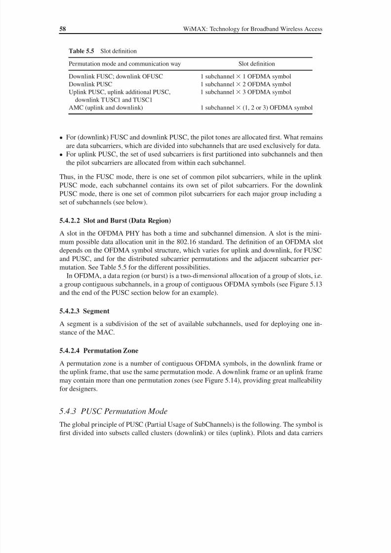
8/10/2019 WiMax-Tech for BBW Access
http://slidepdf.com/reader/full/wimax-tech-for-bbw-access 77/293
58 WiMAX: Technology for Broadband Wireless Access
• For (downlink) FUSC and downlink PUSC, the pilot tones are allocated first. What remains
are data subcarriers, which are divided into subchannels that are used exclusively for data.
• For uplink PUSC, the set of used subcarriers is first partitioned into subchannels and then
the pilot subcarriers are allocated from within each subchannel.
Thus, in the FUSC mode, there is one set of common pilot subcarriers, while in the uplink
PUSC mode, each subchannel contains its own set of pilot subcarriers. For the downlink
PUSC mode, there is one set of common pilot subcarriers for each major group including a
set of subchannels (see below).
5.4.2.2 Slot and Burst (Data Region)
A slot in the OFDMA PHY has both a time and subchannel dimension. A slot is the mini-
mum possible data allocation unit in the 802.16 standard. The definition of an OFDMA slot
depends on the OFDMA symbol structure, which varies for uplink and downlink, for FUSCand PUSC, and for the distributed subcarrier permutations and the adjacent subcarrier per-
mutation. See Table 5.5 for the different possibilities.
In OFDMA, a data region (or burst) is a two-dimensional allocation of a group of slots, i.e.
a group contiguous subchannels, in a group of contiguous OFDMA symbols (see Figure 5.13
and the end of the PUSC section below for an example).
5.4.2.3 Segment
A segment is a subdivision of the set of available subchannels, used for deploying one in-
stance of the MAC.
5.4.2.4 Permutation Zone
A permutation zone is a number of contiguous OFDMA symbols, in the downlink frame or
the uplink frame, that use the same permutation mode. A downlink frame or an uplink frame
may contain more than one permutation zones (see Figure 5.14), providing great malleability
for designers.
5.4.3 PUSC Permutation Mode
The global principle of PUSC (Partial Usage of SubChannels) is the following. The symbol is
first divided into subsets called clusters (downlink) or tiles (uplink). Pilots and data carriers
Table 5.5 Slot definition
Permutation mode and communication way Slot definition
Downlink FUSC; downlink OFUSC 1 subchannel 1 OFDMA symbol
Downlink PUSC 1 subchannel 2 OFDMA symbolUplink PUSC, uplink additional PUSC,
downlink TUSC1 and TUSC1
1 subchannel 3 OFDMA symbol
AMC (uplink and downlink) 1 subchannel (1, 2 or 3) OFDMA symbol

8/10/2019 WiMax-Tech for BBW Access
http://slidepdf.com/reader/full/wimax-tech-for-bbw-access 78/293
Digital Modulation, OFDM and OFDMA 59
are allocated within each subset. This allows partial frequency diversity. Some main MACmessages and some PHY subframe fields are transmitted in the PUSC mode: FCH, DL-MAP
and UL-MAP (see Chapter 9 for these messages). Downlink PUSC subchannel allocation
will now be detailed, which is illustrated by an example.
The global principle of downlink PUSC cluster and subcarrier allocation is illustrated in
Figure 5.15. Considering, for example, a 1024-FFT OFDMA symbol, the number of guard
subcarriers DC carrier is (in the case of 1024 FFT) 92 91 1 184. Therefore, the num-
ber of pilot and data carriers to be distributed is 1024184 840. The parameters of this
numerical example are given in Table 5.6.
SubchannelIndex
OFDM Symbols(time axis)
OFDMSymbol n
OFDMSymbol n +1
Data Region
Figure 5.13 Example of the data region that defines the OFDMA burst allocation
Downlink Subframe
P r e a m
b l e
P U S C
( D L
_ P e r m B a s e P )
P U S C
( D L
_ P e r m B a s e Q )
F U S C
( D L
_ P e r m B a s e R )
A M C
T U S C
1
Uplink Subframe
P U S C
A M C
O p
t i o n a
l P U S C
Figure 5.14 Example of different permutation zones in uplink and downlink frames
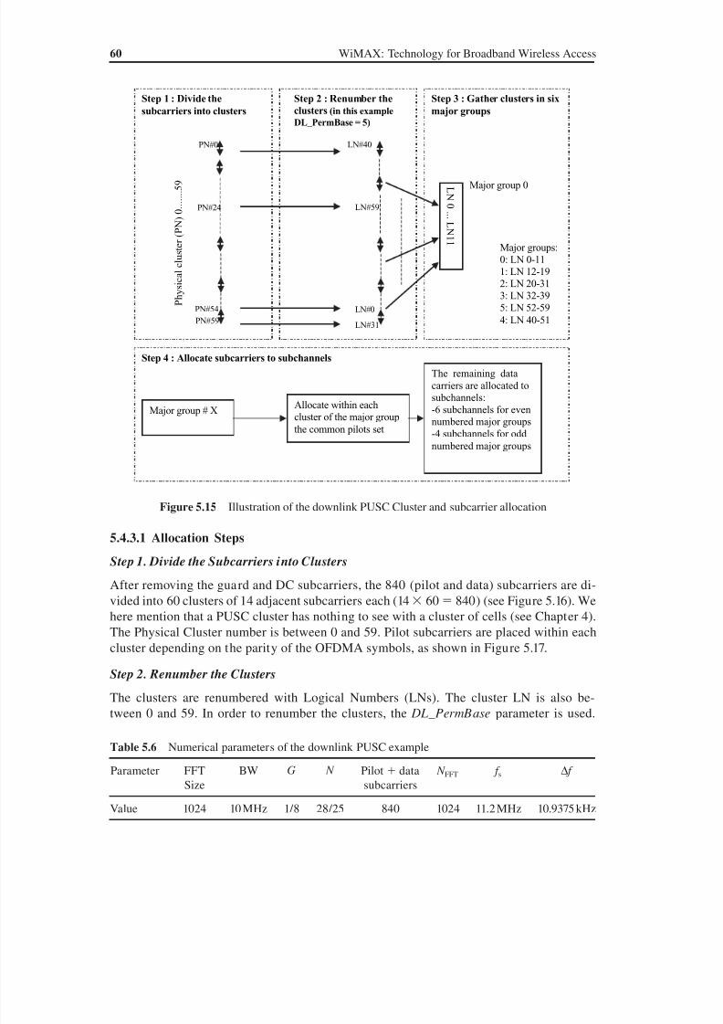
8/10/2019 WiMax-Tech for BBW Access
http://slidepdf.com/reader/full/wimax-tech-for-bbw-access 79/293
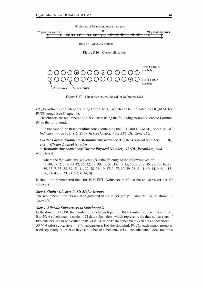
8/10/2019 WiMax-Tech for BBW Access
http://slidepdf.com/reader/full/wimax-tech-for-bbw-access 80/293
Digital Modulation, OFDM and OFDMA 61
DL_ PermBase is an integer ranging from 0 to 31, which can be indicated by DL_MAP for
PUSC zones (see Chapter 9).
The clusters are renumbered to LN clusters using the following formula (denoted Formula
(0) in the following):
In the case of the first downlink zone (containing the FCH and DL-MAP), or Use All SC
Indicator 0 in STC_ DL_ Zone_ IE (see Chapter 9 for STC_ DL_ Zone_ IE):
Cluster Logical Number Renumbering sequence (Cluster Physical Number) (0)
else: Cluster Logical Number
Renumbering sequence(((Cluster Physical Number)13*DL _ PermBase) mod
Nclusters))
where the Renumbering sequence(j) is the jth entry of the following vector:
[6, 48, 37, 21, 31, 40, 42, 56, 32, 47, 30, 33, 54, 18, 10, 15, 50, 51, 58, 46, 23, 45, 16, 57,
39, 35, 7, 55, 25, 59, 53, 11, 22, 38, 28, 19, 17, 3, 27, 12, 29, 26, 5, 41, 49, 44, 9, 8, 1, 13,
36, 14, 43, 2, 20, 24, 52, 4, 34, 0]It should be remembered that, for 1024-FFT, Nclusters 60, so the above vector has 60
elements.
Step 3. Gather Clusters in Six Major Groups
The renumbered clusters are then gathered in six major groups, using the LN, as shown in
Table 5.7.
Step 4. Allocate Subcarriers to Subchannels
In the downlink PUSC the number of subchannels per OFDMA symbol is 30, numbered from
0 to 29. A subchannel is made of 24 data subcarriers, which represents the data subcarriers of
two clusters. It can be verified that: 30 24 720 data subcarriers (720 data subcarriers
30 4 pilot subcarriers 840 subcarriers). For the downlink PUSC, each major group is
used separately in order to have a number of subchannels; i.e. one subchannel does not have
Figure 5.16 Cluster allocation
1024-FFT OFDMA symbol
DC92 guard subcarriers 91 guard subcarriers
60 clusters of 14 adjacent subcarriers each
Even OFDMA
symbols
Odd OFDMA
symbols
P P
PP
Data carrierPilot carrier
Figure 5.17 Cluster structure. (Based on Reference [2].)
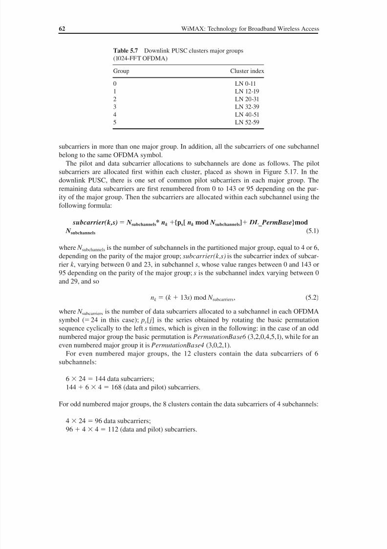
8/10/2019 WiMax-Tech for BBW Access
http://slidepdf.com/reader/full/wimax-tech-for-bbw-access 81/293
62 WiMAX: Technology for Broadband Wireless Access
subcarriers in more than one major group. In addition, all the subcarriers of one subchannel
belong to the same OFDMA symbol.
The pilot and data subcarrier allocations to subchannels are done as follows. The pilotsubcarriers are allocated first within each cluster, placed as shown in Figure 5.17. In the
downlink PUSC, there is one set of common pilot subcarriers in each major group. The
remaining data subcarriers are first renumbered from 0 to 143 or 95 depending on the par-
ity of the major group. Then the subcarriers are allocated within each subchannel using the
following formula:
subcarrier(k,s) N subchannels* nk {ps[ nk mod N subchannels] DL _ PermBase}mod
N subchannels (5.1)
where N subchannels is the number of subchannels in the partitioned major group, equal to 4 or 6,depending on the parity of the major group; subcarrier(k,s) is the subcarrier index of subcar-
rier k , varying between 0 and 23, in subchannel s, whose value ranges between 0 and 143 or
95 depending on the parity of the major group; s is the subchannel index varying between 0
and 29, and so
nk (k 13s) mod N subcarriers, (5.2)
where N subcarriers is the number of data subcarriers allocated to a subchannel in each OFDMA
symbol ( 24 in this case); ps[ j ] is the series obtained by rotating the basic permutation
sequence cyclically to the left s times, which is given in the following: in the case of an odd
numbered major group the basic permutation is PermutationBase6 (3,2,0,4,5,1), while for an
even numbered major group it is PermutationBase4 (3,0,2,1).
For even numbered major groups, the 12 clusters contain the data subcarriers of 6
subchannels:
6 24 144 data subcarriers;
144 6 4 168 (data and pilot) subcarriers.
For odd numbered major groups, the 8 clusters contain the data subcarriers of 4 subchannels:
4 24 96 data subcarriers;
96 4 4 112 (data and pilot) subcarriers.
Table 5.7 Downlink PUSC clusters major groups
(1024-FFT OFDMA)
Group Cluster index
0 LN 0-111 LN 12-19
2 LN 20-31
3 LN 32-39
4 LN 40-51
5 LN 52-59
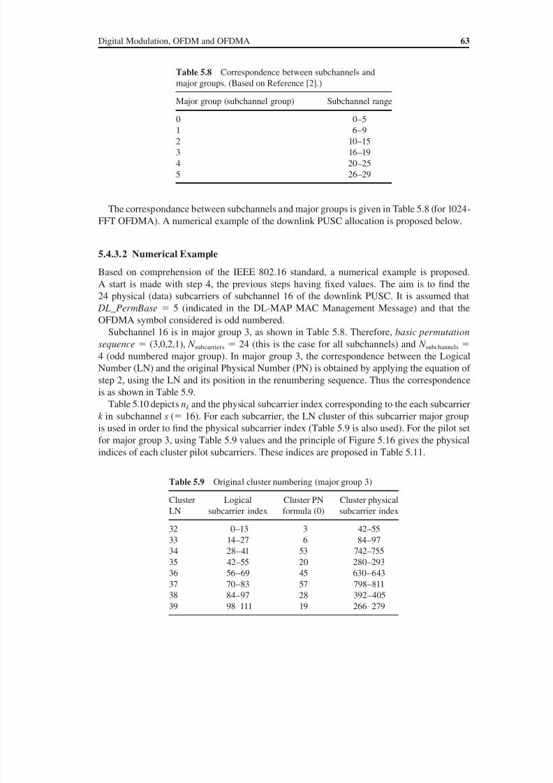
8/10/2019 WiMax-Tech for BBW Access
http://slidepdf.com/reader/full/wimax-tech-for-bbw-access 82/293

8/10/2019 WiMax-Tech for BBW Access
http://slidepdf.com/reader/full/wimax-tech-for-bbw-access 83/293
64 WiMAX: Technology for Broadband Wireless Access
Table 5.10 Subcarrier allocation
Logical
subcarrier
index (k ) in
the considered
subchannel
(s 16)
nk (formula (5.2)) Logical subcarrier index in the major
group (formula (5.1)) and corresponding
cluster LN (using Table 5.9)
Physical subcarrier
index (using Table
5.9 and Figure
5.17)
Subcarrier Cluster LN
0 16 67 37 805
1 17 69 37 807
2 18 76 38 396
3 19 78 38 398
4 20 83 38 403
5 21 85 39 2676 22 92 39 274
7 23 94 39 276
8 0 3 32 45
9 1 5 32 47
10 2 12 32 55
11 3 14 33 86
12 4 19 33 91
13 5 21 33 93
14 6 28 34 746
15 7 30 34 749
16 8 35 34 75317 9 37 35 281
18 10 44 35 288
19 11 46 35 290
20 12 51 36 633
21 13 53 36 635
22 14 60 36 643
23 15 62 37 800
Table 5.11 Pilot subcarrier physical index
Cluster PN Pilot subcarrier physical index
3 42 and 54
6 84 and 96
53 742 and 754
20 280 and 292
45 630 and 642
57 798 and 810
28 392 and 40419 266 and 278
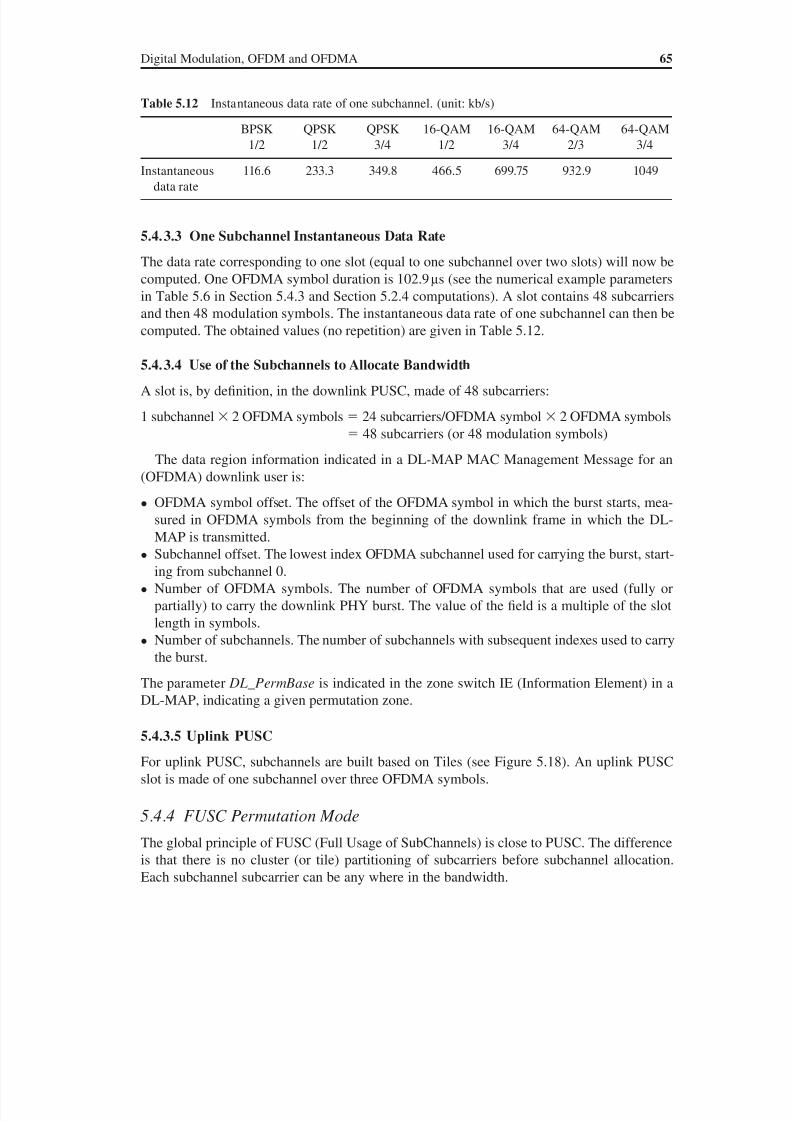
8/10/2019 WiMax-Tech for BBW Access
http://slidepdf.com/reader/full/wimax-tech-for-bbw-access 84/293
Digital Modulation, OFDM and OFDMA 65
5.4.3.3 One Subchannel Instantaneous Data Rate
The data rate corresponding to one slot (equal to one subchannel over two slots) will now be
computed. One OFDMA symbol duration is 102.9 µs (see the numerical example parameters
in Table 5.6 in Section 5.4.3 and Section 5.2.4 computations). A slot contains 48 subcarriers
and then 48 modulation symbols. The instantaneous data rate of one subchannel can then be
computed. The obtained values (no repetition) are given in Table 5.12.
5.4.3.4 Use of the Subchannels to Allocate Bandwidth
A slot is, by definition, in the downlink PUSC, made of 48 subcarriers:
1 subchannel 2 OFDMA symbols 24 subcarriers/OFDMA symbol 2 OFDMA symbols
48 subcarriers (or 48 modulation symbols)
The data region information indicated in a DL-MAP MAC Management Message for an
(OFDMA) downlink user is:
• OFDMA symbol offset. The offset of the OFDMA symbol in which the burst starts, mea-
sured in OFDMA symbols from the beginning of the downlink frame in which the DL-
MAP is transmitted.
• Subchannel offset. The lowest index OFDMA subchannel used for carrying the burst, start-
ing from subchannel 0.
• Number of OFDMA symbols. The number of OFDMA symbols that are used (fully or
partially) to carry the downlink PHY burst. The value of the field is a multiple of the slot
length in symbols.
• Number of subchannels. The number of subchannels with subsequent indexes used to carry
the burst.
The parameter DL_ PermBase is indicated in the zone switch IE (Information Element) in aDL-MAP, indicating a given permutation zone.
5.4.3.5 Uplink PUSC
For uplink PUSC, subchannels are built based on Tiles (see Figure 5.18). An uplink PUSC
slot is made of one subchannel over three OFDMA symbols.
5.4.4 FUSC Permutation Mode
The global principle of FUSC (Full Usage of SubChannels) is close to PUSC. The difference
is that there is no cluster (or tile) partitioning of subcarriers before subchannel allocation.
Each subchannel subcarrier can be any where in the bandwidth.
Table 5.12 Instantaneous data rate of one subchannel. (unit: kb/s)
BPSK
1/2
QPSK
1/2
QPSK
3/4
16-QAM
1/2
16-QAM
3/4
64-QAM
2/3
64-QAM
3/4
Instantaneousdata rate
116.6 233.3 349.8 466.5 699.75 932.9 1049
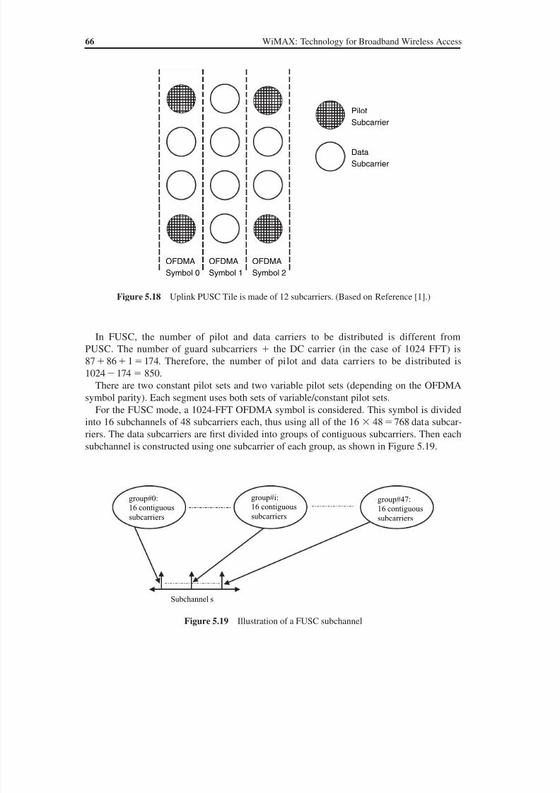
8/10/2019 WiMax-Tech for BBW Access
http://slidepdf.com/reader/full/wimax-tech-for-bbw-access 85/293
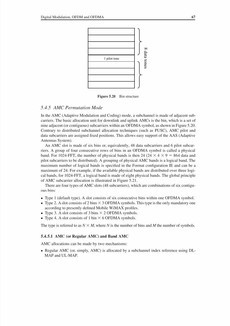
8/10/2019 WiMax-Tech for BBW Access
http://slidepdf.com/reader/full/wimax-tech-for-bbw-access 86/293
Digital Modulation, OFDM and OFDMA 67
5.4.5 AMC Permutation Mode
In the AMC (Adaptive Modulation and Coding) mode, a subchannel is made of adjacent sub-
carriers. The basic allocation unit for downlink and uplink AMCs is the bin, which is a set of
nine adjacent (or contiguous) subcarriers within an OFDMA symbol, as shown in Figure 5.20.
Contrary to distributed subchannel allocation techniques (such as PUSC), AMC pilot and
data subcarriers are assigned fixed positions. This allows easy support of the AAS (Adaptive
Antennas System).
An AMC slot is made of six bins or, equivalently, 48 data subcarriers and 6 pilot subcar-
riers. A group of four consecutive rows of bins in an OFDMA symbol is called a physical
band. For 1024-FFT, the number of physical bands is then 24 (24 4 9 864 data and
pilot subcarriers to be distributed). A grouping of physical AMC bands is a logical band. The
maximum number of logical bands is specified in the Format configuration IE and can be a
maximum of 24. For example, if the available physical bands are distributed over three logi-
cal bands, for 1024-FFT, a logical band is made of eight physical bands. The global principle
of AMC subcarrier allocation is illustrated in Figure 5.21.
There are four types of AMC slots (48 subcarriers), which are combinations of six contigu-
ous bins:
• Type 1 (default type). A slot consists of six consecutive bins within one OFDMA symbol.• Type 2. A slot consists of 2 bins 3 OFDMA symbols. This type is the only mandatory one
according to presently defined Mobile WiMAX profiles.
• Type 3. A slot consists of 3 bins 2 OFDMA symbols.
• Type 4. A slot consists of 1 bin 6 OFDMA symbols.
The type is referred to as N M , where N is the number of bins and M the number of symbols.
5.4.5.1 AMC (or Regular AMC) and Band AMC
AMC allocations can be made by two mechanisms:
• Regular AMC (or, simply, AMC) is allocated by a subchannel index reference using DL-
MAP and UL-MAP.
1 pilot tone
s e n o t a t a d 8
Figure 5.20 Bin structure
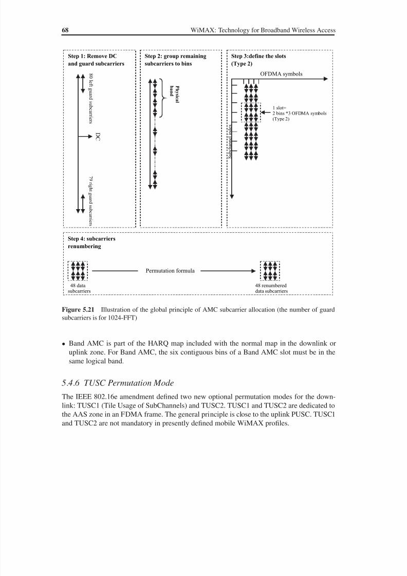
8/10/2019 WiMax-Tech for BBW Access
http://slidepdf.com/reader/full/wimax-tech-for-bbw-access 87/293
68 WiMAX: Technology for Broadband Wireless Access
• Band AMC is part of the HARQ map included with the normal map in the downlink or
uplink zone. For Band AMC, the six contiguous bins of a Band AMC slot must be in thesame logical band.
5.4.6 TUSC Permutation Mode
The IEEE 802.16e amendment defined two new optional permutation modes for the down-
link: TUSC1 (Tile Usage of SubChannels) and TUSC2. TUSC1 and TUSC2 are dedicated to
the AAS zone in an FDMA frame. The general principle is close to the uplink PUSC. TUSC1
and TUSC2 are not mandatory in presently defined mobile WiMAX profiles.
s r e i r r a c b u s d r a u g t h gi r 9 7
s r e i r r a c b u s d r a u g t f e l 0 8
D C
Step 1: Remove DC
and guard subcarriers
Step 2: group remaining
subcarriers to bins
l a c i s yh P
d n a b
Step 3:define the slots
(Type 2)
OFDMA symbols
S u b c h a n n e l i n d e x
1 slot=2 bins *3 OFDMA symbols
(Type 2)
Step 4: subcarriers
renumbering
48 datasubcarriers
48 renumbereddata subcarriers
Permutation formula
Figure 5.21 Illustration of the global principle of AMC subcarrier allocation (the number of guard
subcarriers is for 1024-FFT)

8/10/2019 WiMax-Tech for BBW Access
http://slidepdf.com/reader/full/wimax-tech-for-bbw-access 88/293

8/10/2019 WiMax-Tech for BBW Access
http://slidepdf.com/reader/full/wimax-tech-for-bbw-access 89/293
70 WiMAX: Technology for Broadband Wireless Access
6.2.1 Randomisation
Randomisation introduces protection through information-theoretic uncertainty, avoiding
long sequences of consecutive ones or consecutive zeros. It is also useful for avoiding non-
centred data sequenes. Data randomisation is performed on each downlink and uplink burst
of data. If the amount of data to transmit does not fit exactly the amount of data allocated,
padding of 0FF (‘ones’ only) is added to the end of the transmission block. The Pseudo-
Random Binary Sequence (PRBS) generator used for randomisation is shown in Figure 6.3.
Each data byte to be transmitted enters sequentially into the randomiser, with the Most Sig-
nificant Byte (MSB) first. Preambles are not randomised. The randomiser sequence is applied
only to information bits.
The shift-register of the randomiser is initialised for each new burst allocation. For OFDM
PHY, on the downlink, the randomiser is reinitialised at the start of each frame with the se-
quence: 1 0 0 1 0 1 0 1 0 0 0 0 0 0 0. The randomiser is not reset at the start of burst 1. At the
start of subsequent bursts (starting from burst 2), the randomiser is initialised with the vector
PHY
-sical
PDU
to be
transmitted
Rando-
misation
FECencoder
(CC,
Turbo
Code, …)
Inter-
leaving Modulation
To OFDMA
Part: IFFT,
CP,
Subchannels
etc. (see
Chapter 5)
Repe-
tition
Figure 6.2 OFDMA PHY transmission chain
151413121110987654321
data outdata in
MSBLSB
Figure 6.3 PRBS generator used for data randomisation in OFDM and OFDMA PHY. (From IEEE
Std 802.16-2004 [1]. Copyright IEEE 2004, IEEE. All rights reserved.)
PHYsical
PDUto be
transmitted
Rando-
misation
FECencoder
(CC,
Turbo
Code orother)
Interleaving Modulation
To OFDM
Part: IFFT,
CP, etc. (see
Chapter 5)
Figure 6.1 OFDM PHY transmission chain
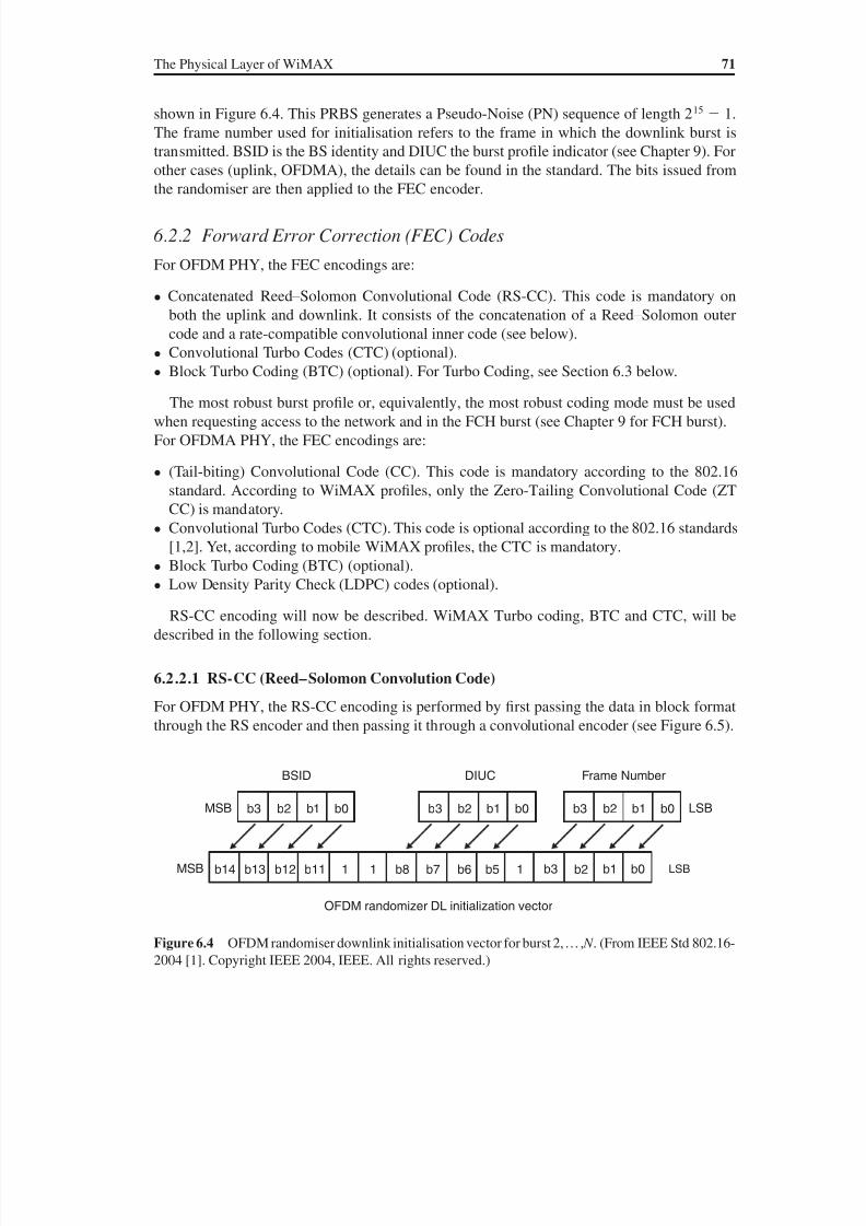
8/10/2019 WiMax-Tech for BBW Access
http://slidepdf.com/reader/full/wimax-tech-for-bbw-access 90/293
The Physical Layer of WiMAX 71
shown in Figure 6.4. This PRBS generates a Pseudo-Noise (PN) sequence of length 215 1.
The frame number used for initialisation refers to the frame in which the downlink burst is
transmitted. BSID is the BS identity and DIUC the burst profile indicator (see Chapter 9). For
other cases (uplink, OFDMA), the details can be found in the standard. The bits issued from
the randomiser are then applied to the FEC encoder.
6.2.2 Forward Error Correction (FEC) Codes
For OFDM PHY, the FEC encodings are:
• Concatenated Reed–Solomon Convolutional Code (RS-CC). This code is mandatory on
both the uplink and downlink. It consists of the concatenation of a Reed–Solomon outer
code and a rate-compatible convolutional inner code (see below).
• Convolutional Turbo Codes (CTC) (optional).
• Block Turbo Coding (BTC) (optional). For Turbo Coding, see Section 6.3 below.
The most robust burst profile or, equivalently, the most robust coding mode must be used
when requesting access to the network and in the FCH burst (see Chapter 9 for FCH burst).
For OFDMA PHY, the FEC encodings are:
• (Tail-biting) Convolutional Code (CC). This code is mandatory according to the 802.16
standard. According to WiMAX profiles, only the Zero-Tailing Convolutional Code (ZT
CC) is mandatory.
• Convolutional Turbo Codes (CTC). This code is optional according to the 802.16 standards
[1,2]. Yet, according to mobile WiMAX profiles, the CTC is mandatory.
• Block Turbo Coding (BTC) (optional).
• Low Density Parity Check (LDPC) codes (optional).
RS-CC encoding will now be described. WiMAX Turbo coding, BTC and CTC, will be
described in the following section.
6.2.2.1 RS-CC (Reed–Solomon Convolution Code)
For OFDM PHY, the RS-CC encoding is performed by first passing the data in block format
through the RS encoder and then passing it through a convolutional encoder (see Figure 6.5).
b3
b14 b13 b12 b11 b8 b7 b6 b51 1 1
BSID
OFDM randomizer DL initialization vector
DIUC Frame Number
LSBMSB
LSBMSB
b2 b1 b0 b3
b3
b2
b2
b1
b1
b0
b0
b3 b2 b1 b0
Figure 6.4 OFDM randomiser downlink initialisation vector for burst 2,… , N . (From IEEE Std 802.16-
2004 [1]. Copyright IEEE 2004, IEEE. All rights reserved.)
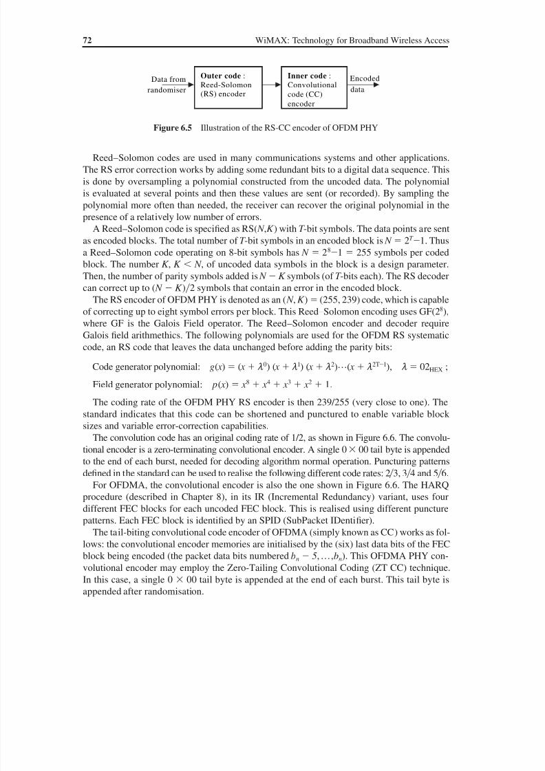
8/10/2019 WiMax-Tech for BBW Access
http://slidepdf.com/reader/full/wimax-tech-for-bbw-access 91/293
72 WiMAX: Technology for Broadband Wireless Access
Reed–Solomon codes are used in many communications systems and other applications.
The RS error correction works by adding some redundant bits to a digital data sequence. This
is done by oversampling a polynomial constructed from the uncoded data. The polynomial
is evaluated at several points and then these values are sent (or recorded). By sampling the
polynomial more often than needed, the receiver can recover the original polynomial in the
presence of a relatively low number of errors.
A Reed–Solomon code is specified as RS( N , K ) with T -bit symbols. The data points are sent
as encoded blocks. The total number of T -bit symbols in an encoded block is N 2T 1. Thus
a Reed–Solomon code operating on 8-bit symbols has N 281 255 symbols per coded
block. The number K , K N , of uncoded data symbols in the block is a design parameter.
Then, the number of parity symbols added is N K symbols (of T -bits each). The RS decoder
can correct up to ( N K )2 symbols that contain an error in the encoded block.
The RS encoder of OFDM PHY is denoted as an ( N , K ) (255, 239) code, which is capable
of correcting up to eight symbol errors per block. This Reed–Solomon encoding uses GF(28),
where GF is the Galois Field operator. The Reed–Solomon encoder and decoder require
Galois field arithmethics. The following polynomials are used for the OFDM RS systematic
code, an RS code that leaves the data unchanged before adding the parity bits:
Code generator polynomial: g( x ) ( x m0) ( x m1) ( x m2)…( x m2T1), m 02HEX ;
Field generator polynomial: p( x ) x 8 x 4 x 3 x 2 1.
The coding rate of the OFDM PHY RS encoder is then 239/255 (very close to one). The
standard indicates that this code can be shortened and punctured to enable variable block
sizes and variable error-correction capabilities.
The convolution code has an original coding rate of 1/2, as shown in Figure 6.6. The convolu-
tional encoder is a zero-terminating convolutional encoder. A single 0 00 tail byte is appended
to the end of each burst, needed for decoding algorithm normal operation. Puncturing patterns
defined in the standard can be used to realise the following different code rates: 23, 34 and 56.
For OFDMA, the convolutional encoder is also the one shown in Figure 6.6. The HARQ
procedure (described in Chapter 8), in its IR (Incremental Redundancy) variant, uses four
different FEC blocks for each uncoded FEC block. This is realised using different puncture
patterns. Each FEC block is identified by an SPID (SubPacket IDentifier).
The tail-biting convolutional code encoder of OFDMA (simply known as CC) works as fol-
lows: the convolutional encoder memories are initialised by the (six) last data bits of the FEC
block being encoded (the packet data bits numbered bn 5,…,bn). This OFDMA PHY con-
volutional encoder may employ the Zero-Tailing Convolutional Coding (ZT CC) technique.
In this case, a single 0 00 tail byte is appended at the end of each burst. This tail byte is
appended after randomisation.
Outer code :
Reed-Solomon(RS) encoder
Inner code :
Convolutional
code (CC)
encoder
Data from
randomiser
Encoded
data
Figure 6.5 Illustration of the RS-CC encoder of OFDM PHY
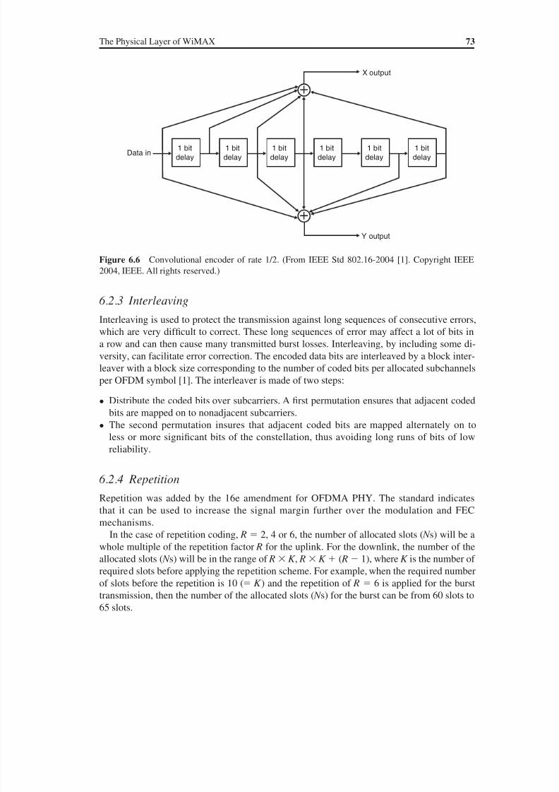
8/10/2019 WiMax-Tech for BBW Access
http://slidepdf.com/reader/full/wimax-tech-for-bbw-access 92/293
The Physical Layer of WiMAX 73
6.2.3 Interleaving
Interleaving is used to protect the transmission against long sequences of consecutive errors,
which are very dif ficult to correct. These long sequences of error may affect a lot of bits in
a row and can then cause many transmitted burst losses. Interleaving, by including some di-
versity, can facilitate error correction. The encoded data bits are interleaved by a block inter-leaver with a block size corresponding to the number of coded bits per allocated subchannels
per OFDM symbol [1]. The interleaver is made of two steps:
• Distribute the coded bits over subcarriers. A first permutation ensures that adjacent coded
bits are mapped on to nonadjacent subcarriers.
• The second permutation insures that adjacent coded bits are mapped alternately on to
less or more significant bits of the constellation, thus avoiding long runs of bits of low
reliability.
6.2.4 RepetitionRepetition was added by the 16e amendment for OFDMA PHY. The standard indicates
that it can be used to increase the signal margin further over the modulation and FEC
mechanisms.
In the case of repetition coding, R 2, 4 or 6, the number of allocated slots ( N s) will be a
whole multiple of the repetition factor R for the uplink. For the downlink, the number of the
allocated slots ( N s) will be in the range of R K , R K ( R 1), where K is the number of
required slots before applying the repetition scheme. For example, when the required number
of slots before the repetition is 10 ( K ) and the repetition of R 6 is applied for the burst
transmission, then the number of the allocated slots ( N s) for the burst can be from 60 slots to
65 slots.
X output
Y output
1 bit
delay
1 bit
delay
1 bit
delay
1 bit
delay
1 bit
delay
1 bit
delayData in
Figure 6.6 Convolutional encoder of rate 1/2. (From IEEE Std 802.16-2004 [1]. Copyright IEEE
2004, IEEE. All rights reserved.)

8/10/2019 WiMax-Tech for BBW Access
http://slidepdf.com/reader/full/wimax-tech-for-bbw-access 93/293
74 WiMAX: Technology for Broadband Wireless Access
The binary data that fits into a region that is repetition coded is reduced by a factor R com-
pared to a nonrepeated region of the slots with the same size and FEC code type. After FEC
and bit-interleaving, the data are segmented into slots, and each group of bits designated to
fit in a slot is repeated R times to form R contiguous slots following the normal slot ordering
that is used for data mapping.This repetition scheme applies only to QPSK modulation. It can be applied in all coding
schemes except HARQ with CTC.
6.3 Turbo Coding
Turbo codes are one of the few FEC codes to come close to the Shannon limit, the theoretical
limit of the maximum information transfer rate over a noisy channel. The turbo codes were
proposed by Berrou and Glavieux (from ENST Bretagne, France) in 1993. The main feature
of turbo codes that make them different from the traditional FEC codes are the use of two
error-correcting codes and an interleaver. Decoding is then made iteratively taking advantageof the two sources of information.
Data transmission is coded as follows (see Figure 6.7). Three blocks of bits are sent. The
first block is the m-bit block of uncoded data. The second block is n2 parity bits added in
sequence for the payload data, computed using a convolutional code. The third subblock is
another n2 parity bits added in sequence for a known permutation of the payload data, also
computed using a convolutional code. Hence, two different redundant blocks of parity bits
are added to the sent payload. The complete block has m n bits of data with a code rate of
m(m n), as shown in the figure.
The data decoding process is the major innovation of turbo codes. The likelihood is used in
order to take advantage of the differences between the two decoders. The turbo code inven-tors like to make the parallel with solving crosswords through both vertical and horizontal
approaches.
Each of the two convolutional decoders generates an hypothesis, with derived likelihoods,
for the m-bits sequence, called the a posteriori probability (APP). The hypothesis and the
received sequence (recalculated) parity bits are compared and, if they differ, the decoder
exchanges the derived likelihoods it has for each bit in the hypotheses. An iterative process
is run until the two convolutional decoders come up with the same hypothesis for the m-bits
sequence. The number of steps is usually of the order of 10.
Coded
Sequence
(m+n bits)Convolutional
Code 1
Convolutional
Code 2
Data
parity bits
n /2
parity bits
n /2
e r u t c n uP
) . t p o (
r e x e l pi t l uM
Interleaver
m
Figure 6.7 Turbo coded sequence generation

8/10/2019 WiMax-Tech for BBW Access
http://slidepdf.com/reader/full/wimax-tech-for-bbw-access 94/293
The Physical Layer of WiMAX 75
6.3.1 Convolutional Turbo Codes (CTC)
Different classes of turbo codes exist. Convolutional Turbo Codes (CTC) are defined as op-
tional FEC for OFDM and OFDMA PHY. For OFDMA PHY, the CTC can be used for the
support of the optional Hybrid ARQ (HARQ, see Chapter 8). According to mobile WiMAXprofiles, the CTC is mandatory for OFDMA PHY. A brief overview of the CTC defined for
OFDMA PHY is proposed here.
The CTC encoder, including its constituent encoder, is depicted in Figure 6.8. It uses a
double binary Circular Recursive Systematic Convolutional Code. The bits of the data to be
encoded are alternatively fed to A and B, starting with the MSB of the first byte being fed
to A. The encoder is fed by blocks of k bits or N couples (k 2 N bits). For all the frame sizes,
k is a multiple of 8 and N is a multiple of 4. Further, N is limited to 8 N 4 1024.
A
CTCinterleaver
Constituentencoder
C11
2
switch
Y1W1
Y2W2
Systematic part
C2
B
A S1 S2
Constituent encoder
Parity part
1
2
S3
B
Figure 6.8 OFDMA PHY Convolutional Turbo Code (CTC) encoder. (From IEEE Std 802.16-2004
[1]. Copyright IEEE 2004, IEEE. All rights reserved.)
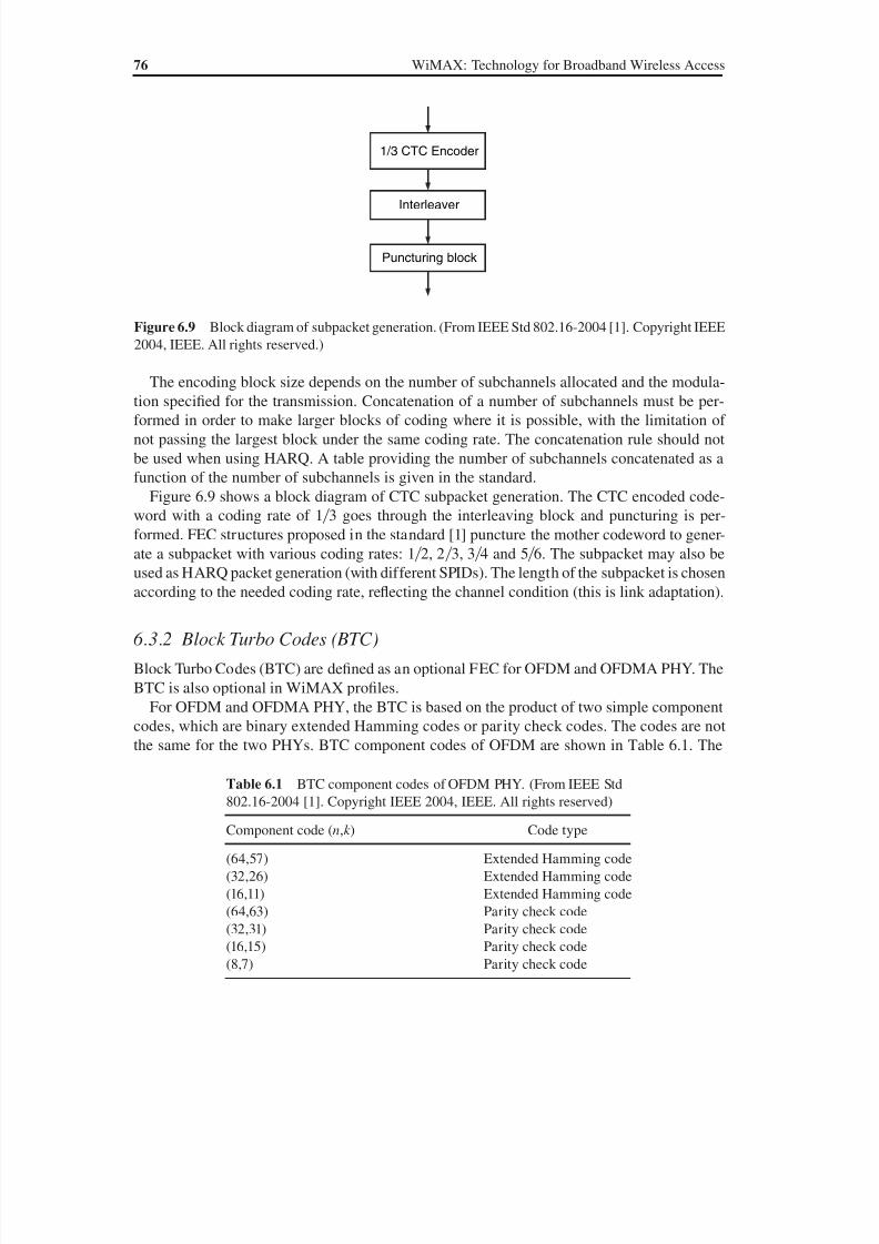
8/10/2019 WiMax-Tech for BBW Access
http://slidepdf.com/reader/full/wimax-tech-for-bbw-access 95/293
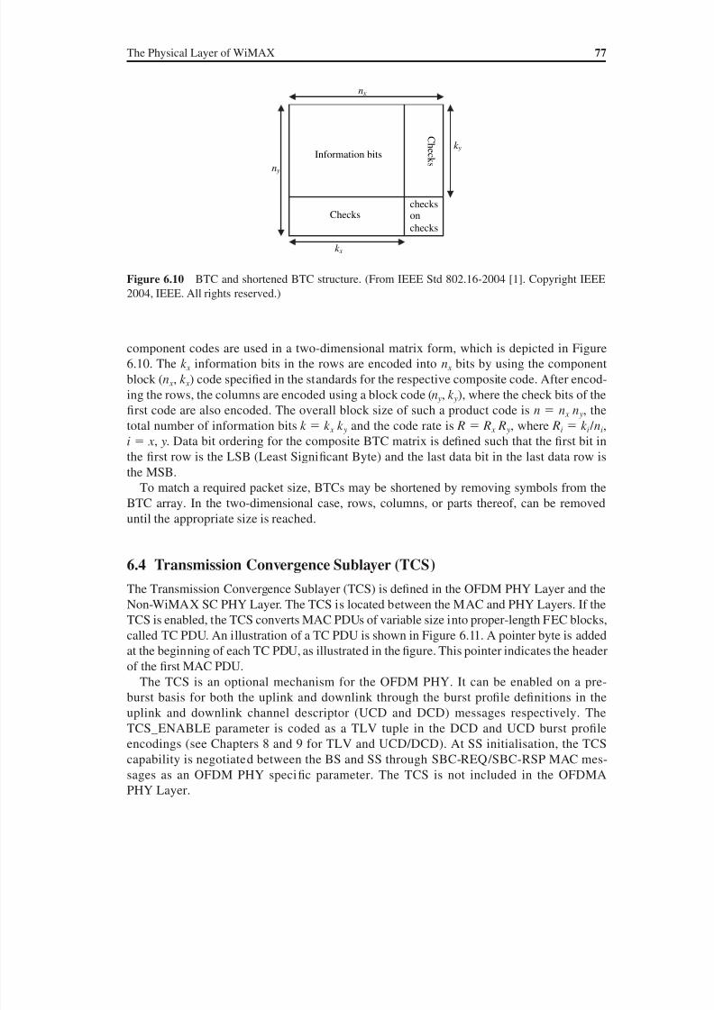
8/10/2019 WiMax-Tech for BBW Access
http://slidepdf.com/reader/full/wimax-tech-for-bbw-access 96/293
The Physical Layer of WiMAX 77
component codes are used in a two-dimensional matrix form, which is depicted in Figure
6.10. The k x information bits in the rows are encoded into n x bits by using the component
block (n x , k x ) code specified in the standards for the respective composite code. After encod-
ing the rows, the columns are encoded using a block code (n y, k y), where the check bits of the
first code are also encoded. The overall block size of such a product code is n n x n y, the
total number of information bits k k x k y and the code rate is R R x R y, where Ri k i / ni,
i x , y. Data bit ordering for the composite BTC matrix is defined such that the first bit in
the first row is the LSB (Least Significant Byte) and the last data bit in the last data row isthe MSB.
To match a required packet size, BTCs may be shortened by removing symbols from the
BTC array. In the two-dimensional case, rows, columns, or parts thereof, can be removed
until the appropriate size is reached.
6.4 Transmission Convergence Sublayer (TCS)
The Transmission Convergence Sublayer (TCS) is defined in the OFDM PHY Layer and the
Non-WiMAX SC PHY Layer. The TCS is located between the MAC and PHY Layers. If the
TCS is enabled, the TCS converts MAC PDUs of variable size into proper-length FEC blocks,
called TC PDU. An illustration of a TC PDU is shown in Figure 6.11. A pointer byte is added
at the beginning of each TC PDU, as illustrated in the figure. This pointer indicates the header
of the first MAC PDU.
The TCS is an optional mechanism for the OFDM PHY. It can be enabled on a pre-
burst basis for both the uplink and downlink through the burst profile definitions in the
uplink and downlink channel descriptor (UCD and DCD) messages respectively. The
TCS_ENABLE parameter is coded as a TLV tuple in the DCD and UCD burst profile
encodings (see Chapters 8 and 9 for TLV and UCD/DCD). At SS initialisation, the TCS
capability is negotiated between the BS and SS through SBC-REQ/SBC-RSP MAC mes-
sages as an OFDM PHY specific parameter. The TCS is not included in the OFDMA
PHY Layer.
Figure 6.10 BTC and shortened BTC structure. (From IEEE Std 802.16-2004 [1]. Copyright IEEE
2004, IEEE. All rights reserved.)
Information bits s k c e h C
Checkscheckson
checks
n x
n y
k x
k y
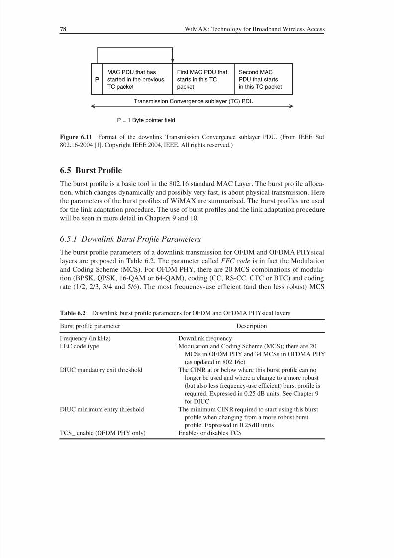
8/10/2019 WiMax-Tech for BBW Access
http://slidepdf.com/reader/full/wimax-tech-for-bbw-access 97/293
78 WiMAX: Technology for Broadband Wireless Access
6.5 Burst Profile
The burst profile is a basic tool in the 802.16 standard MAC Layer. The burst profile alloca-
tion, which changes dynamically and possibly very fast, is about physical transmission. Here
the parameters of the burst profiles of WiMAX are summarised. The burst profiles are used
for the link adaptation procedure. The use of burst profiles and the link adaptation procedure
will be seen in more detail in Chapters 9 and 10.
6.5.1 Downlink Burst Profile Parameters
The burst profile parameters of a downlink transmission for OFDM and OFDMA PHYsicallayers are proposed in Table 6.2. The parameter called FEC code is in fact the Modulation
and Coding Scheme (MCS). For OFDM PHY, there are 20 MCS combinations of modula-
tion (BPSK, QPSK, 16-QAM or 64-QAM), coding (CC, RS-CC, CTC or BTC) and coding
rate (1/2, 2/3, 3/4 and 5/6). The most frequency-use ef ficient (and then less robust) MCS
Figure 6.11 Format of the downlink Transmission Convergence sublayer PDU. (From IEEE Std
802.16-2004 [1]. Copyright IEEE 2004, IEEE. All rights reserved.)
Transmission Convergence sublayer (TC) PDU
P
MAC PDU that has
started in the previous
TC packet
First MAC PDU that
starts in this TC
packet
Second MAC
PDU that starts
in this TC packet
P = 1 Byte pointer field
Table 6.2 Downlink burst profile parameters for OFDM and OFDMA PHYsical layers
Burst profile parameter Description
Frequency (in kHz) Downlink frequencyFEC code type Modulation and Coding Scheme (MCS); there are 20
MCSs in OFDM PHY and 34 MCSs in OFDMA PHY
(as updated in 802.16e)
DIUC mandatory exit threshold The CINR at or below where this burst profile can no
longer be used and where a change to a more robust
(but also less frequency-use ef ficient) burst profile is
required. Expressed in 0.25 dB units. See Chapter 9
for DIUC
DIUC minimum entry threshold The minimum CINR required to start using this burst
profile when changing from a more robust burst
profile. Expressed in 0.25 dB unitsTCS_ enable (OFDM PHY only) Enables or disables TCS
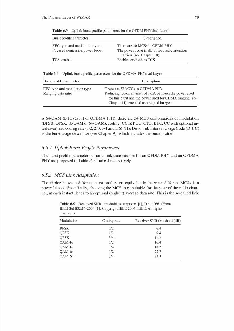
8/10/2019 WiMax-Tech for BBW Access
http://slidepdf.com/reader/full/wimax-tech-for-bbw-access 98/293
The Physical Layer of WiMAX 79
is 64-QAM (BTC) 5/6. For OFDMA PHY, there are 34 MCS combinations of modulation
(BPSK, QPSK, 16-QAM or 64-QAM), coding (CC, ZT CC, CTC, BTC, CC with optional in-
terleaver) and coding rate (1/2, 2/3, 3/4 and 5/6). The Downlink Interval Usage Code (DIUC)
is the burst usage descriptor (see Chapter 9), which includes the burst profile.
6.5.2 Uplink Burst Profile Parameters
The burst profile parameters of an uplink transmission for an OFDM PHY and an OFDMA
PHY are proposed in Tables 6.3 and 6.4 respectively.
6.5.3 MCS Link Adaptation
The choice between different burst profiles or, equivalently, between different MCSs is a
powerful tool. Specifically, choosing the MCS most suitable for the state of the radio chan-
nel, at each instant, leads to an optimal (highest) average data rate. This is the so-called link
Table 6.3 Uplink burst profile parameters for the OFDM PHYsical Layer
Burst profile parameter Description
FEC type and modulation type There are 20 MCSs in OFDM PHY
Focused contention power boost The power boost in dB of focused contentioncarriers (see Chapter 10)
TCS_enable Enables or disables TCS
Table 6.5 Received SNR threshold assumptions [1], Table 266. (From
IEEE Std 802.16-2004 [1]. Copyright IEEE 2004, IEEE. All rights
reserved.)
Modulation Coding rate Receiver SNR threshold (dB)
BPSK 1/2 6.4
QPSK 1/2 9.4
QPSK 3/4 11.2
QAM-16 1/2 16.4
QAM-16 3/4 18.2
QAM-64 1/2 22.7QAM-64 3/4 24.4
Table 6.4 Uplink burst profile parameters for the OFDMA PHYsical Layer
Burst profile parameter Description
FEC type and modulation type There are 52 MCSs in OFDMA PHY
Ranging data ratio Reducing factor, in units of 1 dB, between the power used
for this burst and the power used for CDMA ranging (see
Chapter 11); encoded as a signed integer

8/10/2019 WiMax-Tech for BBW Access
http://slidepdf.com/reader/full/wimax-tech-for-bbw-access 99/293
80 WiMAX: Technology for Broadband Wireless Access
adaptation procedure. In the following chapters the MAC procedures that can be used for the
implementation of link adaptation are described. The link adaptation algorithm in itself is not
indicated in the 802.16 standard. It is left to the vendor or operator.
The order of magnitudes of SNR thresholds can be obtained from Table 6.5, proposed in
the standard [1] for some test conditions. These SNR thresholds are for a BER, Bit-Error Rate,measured after the FEC, that is smaller than 10–6.
8/10/2019 WiMax-Tech for BBW Access
http://slidepdf.com/reader/full/wimax-tech-for-bbw-access 100/293
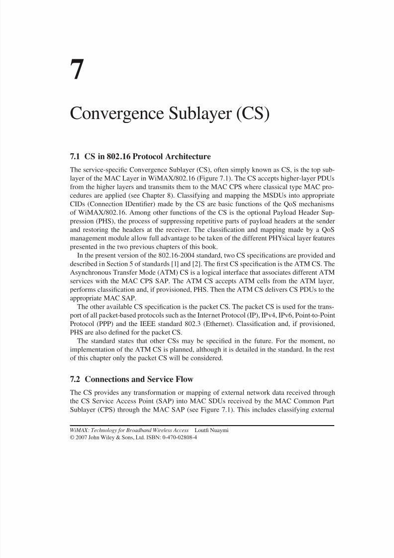
8/10/2019 WiMax-Tech for BBW Access
http://slidepdf.com/reader/full/wimax-tech-for-bbw-access 101/293
7Convergence Sublayer (CS)
7.1 CS in 802.16 Protocol Architecture
The service-specific Convergence Sublayer (CS), often simply known as CS, is the top sub-layer of the MAC Layer in WiMAX/802.16 (Figure 7.1). The CS accepts higher-layer PDUs
from the higher layers and transmits them to the MAC CPS where classical type MAC pro-
cedures are applied (see Chapter 8). Classifying and mapping the MSDUs into appropriate
CIDs (Connection IDentifier) made by the CS are basic functions of the QoS mechanisms
of WiMAX/802.16. Among other functions of the CS is the optional Payload Header Sup-
pression (PHS), the process of suppressing repetitive parts of payload headers at the sender
and restoring the headers at the receiver. The classification and mapping made by a QoS
management module allow full advantage to be taken of the different PHYsical layer features
presented in the two previous chapters of this book.
In the present version of the 802.16-2004 standard, two CS specifications are provided anddescribed in Section 5 of standards [1] and [2]. The first CS specification is the ATM CS. The
Asynchronous Transfer Mode (ATM) CS is a logical interface that associates different ATM
services with the MAC CPS SAP. The ATM CS accepts ATM cells from the ATM layer,
performs classification and, if provisioned, PHS. Then the ATM CS delivers CS PDUs to the
appropriate MAC SAP.
The other available CS specification is the packet CS. The packet CS is used for the trans-
port of all packet-based protocols such as the Internet Protocol (IP), IPv4, IPv6, Point-to-Point
Protocol (PPP) and the IEEE standard 802.3 (Ethernet). Classification and, if provisioned,
PHS are also defined for the packet CS.
The standard states that other CSs may be specified in the future. For the moment, noimplementation of the ATM CS is planned, although it is detailed in the standard. In the rest
of this chapter only the packet CS will be considered.
7.2 Connections and Service Flow
The CS provides any transformation or mapping of external network data received through
the CS Service Access Point (SAP) into MAC SDUs received by the MAC Common Part
Sublayer (CPS) through the MAC SAP (see Figure 7.1). This includes classifying external
WiMAX: Technology for Broadband Wireless Access Loutfi Nuaymi
© 2007 John Wiley & Sons, Ltd. ISBN: 0-470-02808-4
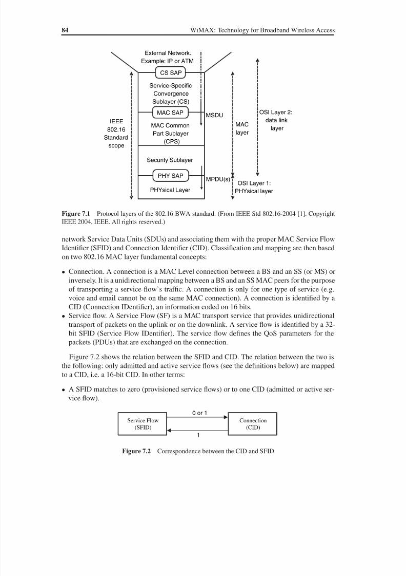
8/10/2019 WiMax-Tech for BBW Access
http://slidepdf.com/reader/full/wimax-tech-for-bbw-access 102/293
84 WiMAX: Technology for Broadband Wireless Access
network Service Data Units (SDUs) and associating them with the proper MAC Service Flow
Identifier (SFID) and Connection Identifier (CID). Classification and mapping are then based
on two 802.16 MAC layer fundamental concepts:
• Connection. A connection is a MAC Level connection between a BS and an SS (or MS) or
inversely. It is a unidirectional mapping between a BS and an SS MAC peers for the purpose
of transporting a service flow’s traffic. A connection is only for one type of service (e.g.
voice and email cannot be on the same MAC connection). A connection is identified by a
CID (Connection IDentifier), an information coded on 16 bits.
• Service flow. A Service Flow (SF) is a MAC transport service that provides unidirectional
transport of packets on the uplink or on the downlink. A service flow is identified by a 32-
bit SFID (Service Flow IDentifier). The service flow defines the QoS parameters for the
packets (PDUs) that are exchanged on the connection.
Figure 7.2 shows the relation between the SFID and CID. The relation between the two is
the following: only admitted and active service flows (see the definitions below) are mapped
to a CID, i.e. a 16-bit CID. In other terms:
• A SFID matches to zero (provisioned service flows) or to one CID (admitted or active ser-
vice flow).
OSI Layer 1:
PHYsical layer
MAC
layer
Service-SpecificConvergence
Sublayer (CS)
CS SAP
MAC SAP
MAC Common
Part Sublayer
(CPS)
Security Sublayer
PHY SAP
PHYsical Layer
IEEE
802.16
Standard
scope
External Network.
Example: IP or ATM
MSDU
MPDU(s)
OSI Layer 2:
data link
layer
Figure 7.1 Protocol layers of the 802.16 BWA standard. (From IEEE Std 802.16-2004 [1]. Copyright
IEEE 2004, IEEE. All rights reserved.)
Service Flow
(SFID)
Connection
(CID)
1
0 or 1
Figure 7.2 Correspondence between the CID and SFID
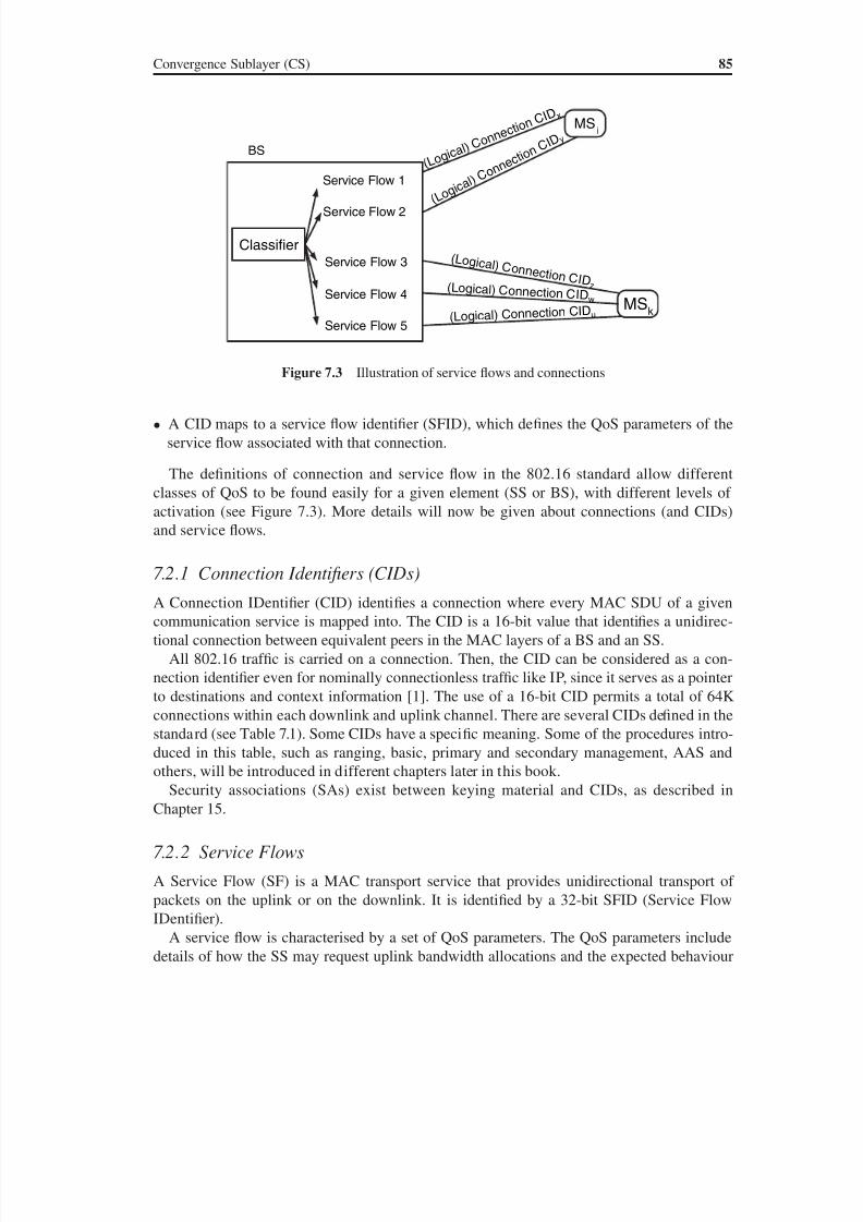
8/10/2019 WiMax-Tech for BBW Access
http://slidepdf.com/reader/full/wimax-tech-for-bbw-access 103/293
Convergence Sublayer (CS) 85
• A CID maps to a service flow identifier (SFID), which defines the QoS parameters of the
service flow associated with that connection.
The definitions of connection and service flow in the 802.16 standard allow different
classes of QoS to be found easily for a given element (SS or BS), with different levels of
activation (see Figure 7.3). More details will now be given about connections (and CIDs)
and service flows.
7.2.1 Connection Identifiers (CIDs)
A Connection IDentifier (CID) identifies a connection where every MAC SDU of a given
communication service is mapped into. The CID is a 16-bit value that identifies a unidirec-
tional connection between equivalent peers in the MAC layers of a BS and an SS.
All 802.16 traf fic is carried on a connection. Then, the CID can be considered as a con-
nection identifier even for nominally connectionless traf fic like IP, since it serves as a pointer
to destinations and context information [1]. The use of a 16-bit CID permits a total of 64K
connections within each downlink and uplink channel. There are several CIDs defined in the
standard (see Table 7.1). Some CIDs have a specific meaning. Some of the procedures intro-
duced in this table, such as ranging, basic, primary and secondary management, AAS and
others, will be introduced in different chapters later in this book.
Security associations (SAs) exist between keying material and CIDs, as described in
Chapter 15.
7.2.2 Service Flows
A Service Flow (SF) is a MAC transport service that provides unidirectional transport of
packets on the uplink or on the downlink. It is identified by a 32-bit SFID (Service Flow
IDentifier).
A service flow is characterised by a set of QoS parameters. The QoS parameters include
details of how the SS may request uplink bandwidth allocations and the expected behaviour
BS
Service Flow 1
Service Flow 2
Service Flow 4
Service Flow 5
Service Flow 3
Classifier
MSi
( L o g i c a
l ) C o n n
e c t i o n C
I D x
( L o g i c a l )
C o n n e
c t i o n C
I D y
MSk
( Lo g i c al ) C o n n e c t i o n C I D z ( Logical) Connect ion CIDw
(Logical) Connec tion CIDu
Figure 7.3 Illustration of service flows and connections

8/10/2019 WiMax-Tech for BBW Access
http://slidepdf.com/reader/full/wimax-tech-for-bbw-access 104/293
8/10/2019 WiMax-Tech for BBW Access
http://slidepdf.com/reader/full/wimax-tech-for-bbw-access 105/293
Convergence Sublayer (CS) 87
of the BS uplink scheduler. The main QoS parameters of the 802.16-2004 standard are given
in Section 7.4 below. The service flow attributes are now given.
7.2.2.1 Service Flow Attributes
A service flow is partially characterised by the following attributes:
• Service Flow ID. An SFID is assigned to each existing service flow. The SFID serves as the
identifier for the service flow in the network.
• CID. Mapping a CID to an SFID exists only when the connection has an admitted or active
service flow (see below).
• ProvisionedQoSParamSet. This defines a QoS parameter set that is provisioned via means
that the standard assumes to be outside of its scope. The standard states that this could be
part of the network management system. For example, the service (or QoS) class name is an
attribute of the ProvisionedQoSParamSet. There are five QoS classes, the fifth having beenadded by the 802.16e amendment.
• AdmittedQoSParamSet. This defines a set of QoS parameters for which the BS, and pos-
sibly the SS, are reserved resources. The principal resource to be reserved is bandwidth,
but this also includes any other memory or time-based resource required to subsequently
activate the flow.
• ActiveQoSParamSet. This defines a set of QoS parameters defining the service actually
being provided to the service flow. Only an active service flow may forward packets.
The activation state of the service flow is determined by the ActiveQoSParamSet. If the
ActiveQoSParamSet is null, then the service flow is inactive.
• Authorisation module. This is a logical function within the BS that approves or denies everychange to QoS parameters and classifiers associated with a service flow. As such, it defines
an ‘envelope’ that limits the possible values of the AdmittedQoSParamSet and ActiveQoS-
ParamSet (see Section 11.5.4 for more details about the authorisation module).
7.2.2.2 Types of Service Flow
The standard has defined three types of service flow:
• Provisioned service flows. This type of service flow is known via provisioning by, for exam-
ple, the network management system. Its AdmittedQoSParamSet and ActiveQoSParamSetare both null.
• Admitted service flow. The standard supports a two-phase activation model that is often
used in telephony applications. In the two-phase activation model, the resources for a call
are first ‘admitted’ and then, once the end-to-end negotiation is completed, the resources
are ‘activated’.
• Active service flow. This type of service flow has resources committed by the BS for its
ActiveQoSParamSet. Its ActiveQoSParamSet is non-null.
Each service flow class is associated with the corresponding QoSParametersSets. These
three types of service flows can be seen as complementary. Figure 7.4 shows the possible
transitions between these different service flows. A BS may choose to activate a provisioned
service flow directly, or may choose to take the path to active service flows by passing the

8/10/2019 WiMax-Tech for BBW Access
http://slidepdf.com/reader/full/wimax-tech-for-bbw-access 106/293
88 WiMAX: Technology for Broadband Wireless Access
admitted service flows. The model structure of these three service flow types is shown in
Figure 7.5, taken from the standard.
More details about the activation of a service flow are given in Section 11.5. Having intro-
duced the concepts of CID and SFID and their attributes, it is now possible to describe the
process of classification and mapping made in the CS.
7.3 Classification and MappingAs defined in the standard, classification is the process by which a MAC SDU is mapped on
to a particular connection for transmission between MAC peers. The mapping process associ-
ates a MAC SDU with a connection, which also creates an association with the service flow
characteristics of that connection. This process allows 802.16 BWA to deliver MAC SDUs
with the appropriate QoS constraints.
Classification and mapping mechanisms exist in the uplink and downlink. In the case of
a downlink transmission, the classifier will be present in the BS and in the case of an uplink
transmission it is present in the SS.
A classifier is a set of matching criteria applied to each packet entering the WiMAX/802.16
network [1]. The set of matching criteria consists of some protocol-specific packet match-
ing criteria (a destination IP address, for example), a classifier priority and a reference to a
Provisionedservice flows
(Initial state)
Activeservice flows
(Final state)
Admittedservice flows
(Intermediate state)
Figure 7.4 Possible transitions between service flows [1]
Provisioned service flows
(SFIDs)
Admitted service flow
(SFIDs and CIDs)
Active service flow
(SFIDs and Active CIDs)
Figure 7.5 Model structure of the service flow types. (From IEEE Std 802.16-2004 [1]. CopyrightIEEE 2004, IEEE. All rights reserved.)

8/10/2019 WiMax-Tech for BBW Access
http://slidepdf.com/reader/full/wimax-tech-for-bbw-access 107/293
Convergence Sublayer (CS) 89
CID. If a packet matches the specified packet matching criteria, it is then delivered to the
SAP for delivery on the connection defined by the CID. The service flow characteristics of
the connection provide the QoS for that packet. The classification mechanism is shown inFigure 7.6.
The MAC of 802.16-2004 is connection-oriented, where the connections are virtual. For
the purposes of mapping simultaneous different services and associating varying levels of
QoS, all data communications are in the context of a connection. Service flows may be pro-
visioned when an SS is installed in the system. Shortly after SS registration, connections are
associated with these service flows (it should be remembered that there is one connection
per service flow) to provide a reference for the process of bandwidth request. Additionally,
new connections may be established when an SS service needs change. A connection defines
both the mapping between peer convergence processes that utilise the MAC and a service
flow. The service flow defines the QoS parameters for the PDUs that are exchanged on the
connection.
In short, the MAC CS Layer classifies each application. A QoS class is assigned. This
classification is an important process because each BS may serve a relatively large number
of users transmitting different applications. This classification allows a good link adap-
tation, because it will allocate the needed resources for each application. Consequently,
the QoS differentiation, e.g. between an email and a voice transmission, is very easy to
implement.
A Dynamic Service Addition (DSA) MAC management message allows the creation of
a new service flow. MAC management messages are introduced in Chapter 8. The use of a
DSA message for the creation of a new service flow is detailed in Chapter 11. The attributes
of QoS are now given.
Figure 7.6 Classification and CID mapping. The principle is the same for both ways: BS to SS and SS
to BS. (From IEEE Std 802.16-2004 [1]. Copyright IEEE 2004, IEEE. All rights reserved.)
Upper Layer Entity(e.g., bridge, router, host)
SDU
SAP
Classifier
CID #1
CID #2
CID #...
CID #n{SDU, CID …}
802.16 MAC CPS
SAP
{SDU, CID …}
SAP
Reconstitution(e.g., undo PHS)
SDU
Upper Layer Entity(e.g., bridge, router, host)
802.16 MAC CPS
SAP
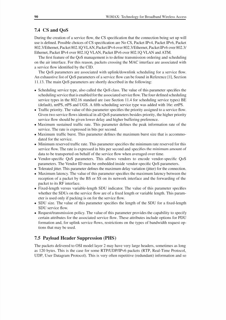
8/10/2019 WiMax-Tech for BBW Access
http://slidepdf.com/reader/full/wimax-tech-for-bbw-access 108/293
90 WiMAX: Technology for Broadband Wireless Access
7.4 CS and QoS
During the creation of a service flow, the CS specification that the connection being set up will
use is defined. Possible choices of CS specification are No CS, Packet IPv4, Packet IPv6, Packet
802.3/Ethernet, Packet 802.1Q VLAN, Packet IPv4 over 802.3/Ethernet, Packet IPv6 over 802.3/ Ethernet, Packet IPv4 over 802.1Q VLAN, Packet IPv6 over 802.1Q VLAN and ATM.
The first feature of the QoS management is to define transmission ordering and scheduling
on the air interface. For this reason, packets crossing the MAC interface are associated with
a service flow identified by the CID.
The QoS parameters are associated with uplink/downlink scheduling for a service flow.
An exhaustive list of QoS parameters of a service flow can be found in Reference [1], Section
11.13. The main QoS parameters are shortly described in the following:
• Scheduling service type, also called the QoS class. The value of this parameter specifies the
scheduling service that is enabled for the associated service flow. The four defined scheduling
service types in the 802.16 standard are (see Section 11.4 for scheduling service types) BE
(default), nrtPS, rtPS and UGS. A fifth scheduling service type was added with 16e: ertPS.
• Traf fic priority. The value of this parameter specifies the priority assigned to a service flow.
Given two service flows identical in all QoS parameters besides priority, the higher priority
service flow should be given lower delay and higher buffering preference.
• Maximum sustained traf fic rate. This parameter defines the peak information rate of the
service. The rate is expressed in bits per second.
• Maximum traf fic burst. This parameter defines the maximum burst size that is accommo-
dated for the service.
• Minimum reserved traf fic rate. This parameter specifies the minimum rate reserved for thisservice flow. The rate is expressed in bits per second and specifies the minimum amount of
data to be transported on behalf of the service flow when averaged over time.
• Vendor-specific QoS parameters. This allows vendors to encode vendor-specific QoS
parameters. The Vendor ID must be embedded inside vendor-specific QoS parameters.
• Tolerated jitter. This parameter defines the maximum delay variation (jitter) for the connection.
• Maximum latency. The value of this parameter specifies the maximum latency between the
reception of a packet by the BS or SS on its network interface and the forwarding of the
packet to its RF interface.
• Fixed-length versus variable-length SDU indicator. The value of this parameter specifies
whether the SDUs on the service flow are of a fixed length or variable length. This param-eter is used only if packing is on for the service flow.
• SDU size. The value of this parameter specifies the length of the SDU for a fixed-length
SDU service flow.
• Request/transmission policy. The value of this parameter provides the capability to specify
certain attributes for the associated service flow. These attributes include options for PDU
formation and, for uplink service flows, restrictions on the types of bandwidth request op-
tions that may be used.
7.5 Payload Header Suppression (PHS)
The packets delivered to OSI model layer 2 may have very large headers, sometimes as long
as 120 bytes. This is the case for some RTP/UDP/IPv6 packets (RTP, Real-Time Protocol,
UDP, User Datagram Protocol). This is very often repetitive (redundant) information and so
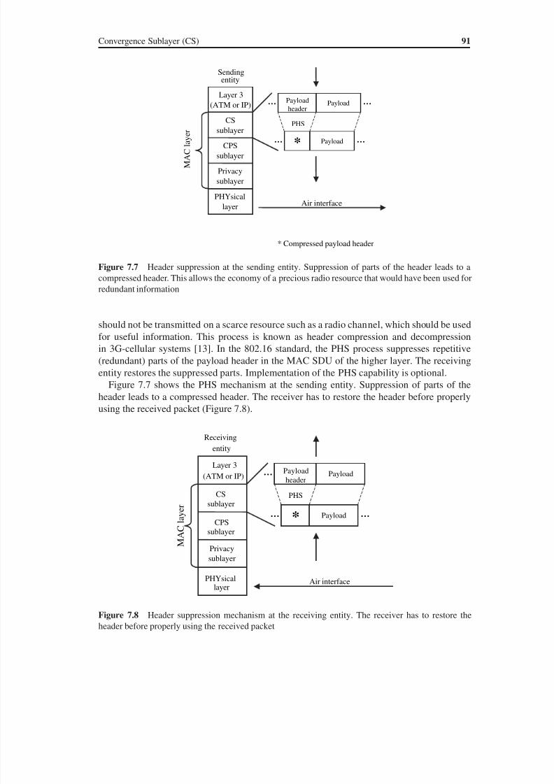
8/10/2019 WiMax-Tech for BBW Access
http://slidepdf.com/reader/full/wimax-tech-for-bbw-access 109/293
Convergence Sublayer (CS) 91
should not be transmitted on a scarce resource such as a radio channel, which should be used
for useful information. This process is known as header compression and decompression
in 3G-cellular systems [13]. In the 802.16 standard, the PHS process suppresses repetitive
(redundant) parts of the payload header in the MAC SDU of the higher layer. The receiving
entity restores the suppressed parts. Implementation of the PHS capability is optional.
Figure 7.7 shows the PHS mechanism at the sending entity. Suppression of parts of the
header leads to a compressed header. The receiver has to restore the header before properly
using the received packet (Figure 7.8).
Sendingentity
Layer 3
(ATM or IP)
PHYsical
layer
CSsublayer
CPS
sublayer
Privacy
sublayer
Payload
headerPayload
Payload
PHS
*
Air interface
……
……
* Compressed payload header
r e y a l C A M
Figure 7.7 Header suppression at the sending entity. Suppression of parts of the header leads to a
compressed header. This allows the economy of a precious radio resource that would have been used for
redundant information
Receiving
entity
Layer 3
(ATM or IP)
PHYsicallayer
CS
sublayer
CPS
sublayer
Privacy
sublayer
r e y a l C A M
Payload
header Payload
Payload
PHS
Air interface
…
… …*
Figure 7.8 Header suppression mechanism at the receiving entity. The receiver has to restore the
header before properly using the received packet
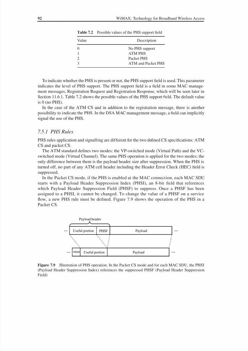
8/10/2019 WiMax-Tech for BBW Access
http://slidepdf.com/reader/full/wimax-tech-for-bbw-access 110/293
92 WiMAX: Technology for Broadband Wireless Access
To indicate whether the PHS is present or not, the PHS support field is used. This parameter
indicates the level of PHS support. The PHS support field is a field in some MAC manage-
ment messages, Registration Request and Registration Response, which will be seen later in
Section 11.6.1. Table 7.2 shows the possible values of the PHS support field. The default value
is 0 (no PHS).
In the case of the ATM CS and in addition to the registration message, there is anotherpossibility to indicate the PHS. In the DSA MAC management message, a field can implicitly
signal the use of the PHS.
7.5.1 PHS Rules
PHS rules application and signalling are different for the two defined CS specifications: ATM
CS and packet CS.
The ATM standard defines two modes: the VP-switched mode (Virtual Path) and the VC-
switched mode (Virtual Channel). The same PHS operation is applied for the two modes; the
only difference between them is the payload header size after suppression. When the PHS is
turned off, no part of any ATM cell header including the Header Error Check (HEC) field is
suppressed.
In the Packet CS mode, if the PHS is enabled at the MAC connection, each MAC SDU
starts with a Payload Header Suppression Index (PHSI), an 8-bit field that references
which Payload Header Suppression Field (PHSF) to suppress. Once a PHSF has been
assigned to a PHSI, it cannot be changed. To change the value of a PHSF on a service
flow, a new PHS rule must be defined. Figure 7.9 shows the operation of the PHS in a
Packet CS.
Payload header
Payload
PayloadPHSI
Useful portion
Useful portion
…
…
…
…
PHSF
Figure 7.9 Illustration of PHS operation. In the Packet CS mode and for each MAC SDU, the PHSI(Payload Header Suppression Index) references the suppressed PHSF (Payload Header Suppression
Field)
Table 7.2 Possible values of the PHS support field
Value Description
0 No PHS support
1 ATM PHS2 Packet PHS
3 ATM and Packet PHS
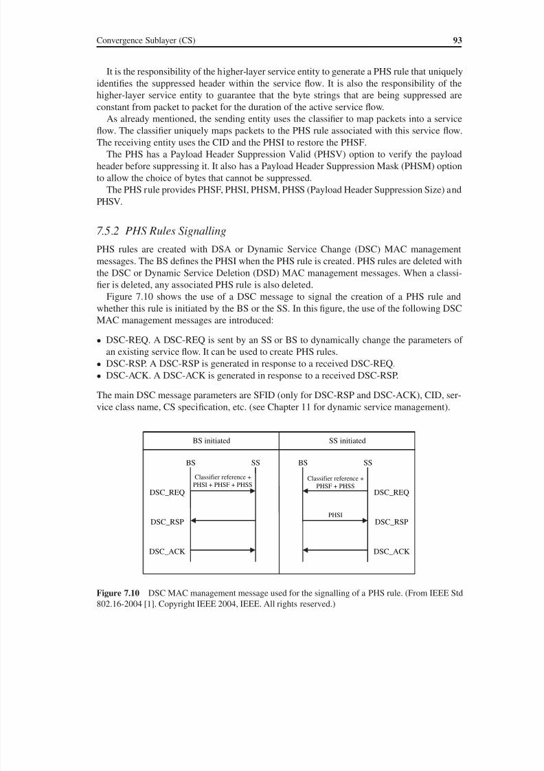
8/10/2019 WiMax-Tech for BBW Access
http://slidepdf.com/reader/full/wimax-tech-for-bbw-access 111/293
Convergence Sublayer (CS) 93
It is the responsibility of the higher-layer service entity to generate a PHS rule that uniquely
identifies the suppressed header within the service flow. It is also the responsibility of the
higher-layer service entity to guarantee that the byte strings that are being suppressed are
constant from packet to packet for the duration of the active service flow.
As already mentioned, the sending entity uses the classifier to map packets into a serviceflow. The classifier uniquely maps packets to the PHS rule associated with this service flow.
The receiving entity uses the CID and the PHSI to restore the PHSF.
The PHS has a Payload Header Suppression Valid (PHSV) option to verify the payload
header before suppressing it. It also has a Payload Header Suppression Mask (PHSM) option
to allow the choice of bytes that cannot be suppressed.
The PHS rule provides PHSF, PHSI, PHSM, PHSS (Payload Header Suppression Size) and
PHSV.
7.5.2 PHS Rules SignallingPHS rules are created with DSA or Dynamic Service Change (DSC) MAC management
messages. The BS defines the PHSI when the PHS rule is created. PHS rules are deleted with
the DSC or Dynamic Service Deletion (DSD) MAC management messages. When a classi-
fier is deleted, any associated PHS rule is also deleted.
Figure 7.10 shows the use of a DSC message to signal the creation of a PHS rule and
whether this rule is initiated by the BS or the SS. In this figure, the use of the following DSC
MAC management messages are introduced:
• DSC-REQ. A DSC-REQ is sent by an SS or BS to dynamically change the parameters of
an existing service flow. It can be used to create PHS rules.• DSC-RSP. A DSC-RSP is generated in response to a received DSC-REQ.
• DSC-ACK. A DSC-ACK is generated in response to a received DSC-RSP.
The main DSC message parameters are SFID (only for DSC-RSP and DSC-ACK), CID, ser-
vice class name, CS specification, etc. (see Chapter 11 for dynamic service management).
BS initiated SS initiated
SSBS BS SS
DSC_REQ
DSC_RSP
DSC_ACK
DSC_REQ
DSC_RSP
DSC_ACK
Classifier reference +
PHSI + PHSF + PHSSClassifier reference +
PHSF + PHSS
PHSI
Figure 7.10 DSC MAC management message used for the signalling of a PHS rule. (From IEEE Std
802.16-2004 [1]. Copyright IEEE 2004, IEEE. All rights reserved.)
8/10/2019 WiMax-Tech for BBW Access
http://slidepdf.com/reader/full/wimax-tech-for-bbw-access 112/293
94 WiMAX: Technology for Broadband Wireless Access
7.5.3 Header Compression in WiMAX
The PHS is a header suppression mechanism. There are also header compression algorithms
that compress packet headers by other means than repetitive header suppression. The 802.16e
amendment mentions that the Convergence Sublayer (CS) supports SDUs in two formats thatfacilitate robust compression of IP and higher-layer headers. These formats (corresponding to
header compression algorithms) are:
• ROHC (RObust Header Compression), IETF RFC 3095 [14]. ROHC is also used in 3G
UMTS cellular systems for header compression.
• ECRTP (Enhanced Compressed Real-Time Protocol) or Enhanced Compressed, RFC 3545
[15]. ECRTP is an evolution of CRTP, Compressed RTP, RFC 2508, defined for low data
rate fixed line IP/UDP/RTP packet headers.
These two CS PDU formats defined in 802.16e are referred to as the IPheader-compression
CS PDU format.Compressed-IP-Header classifiers operate on the context fields of the ROHC and ECRTP
compressed packets. 802.16e provides the service flow encodings that should be included
in the CS packets for ROHC and ECRTP. 802.16e indicates that the compression function
must not operate on the IEEE 802.3/Ethernet frame header so that the Ethernet frame header
remains intact.
8/10/2019 WiMax-Tech for BBW Access
http://slidepdf.com/reader/full/wimax-tech-for-bbw-access 113/293
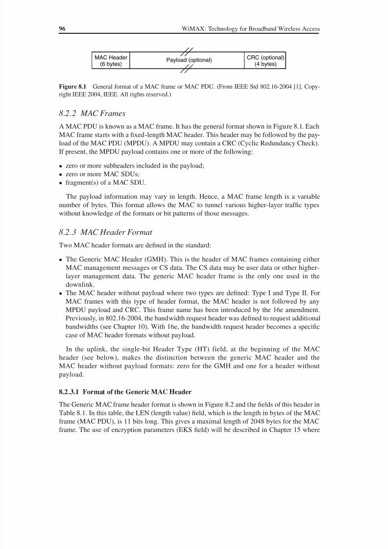
8/10/2019 WiMax-Tech for BBW Access
http://slidepdf.com/reader/full/wimax-tech-for-bbw-access 114/293
96 WiMAX: Technology for Broadband Wireless Access
8.2.2 MAC Frames
A MAC PDU is known as a MAC frame. It has the general format shown in Figure 8.1. Each
MAC frame starts with a fixed-length MAC header. This header may be followed by the pay-
load of the MAC PDU (MPDU). A MPDU may contain a CRC (Cyclic Redundancy Check).
If present, the MPDU payload contains one or more of the following:
• zero or more subheaders included in the payload;• zero or more MAC SDUs;
• fragment(s) of a MAC SDU.
The payload information may vary in length. Hence, a MAC frame length is a variable
number of bytes. This format allows the MAC to tunnel various higher-layer traffic types
without knowledge of the formats or bit patterns of those messages.
8.2.3 MAC Header Format
Two MAC header formats are defined in the standard:
• The Generic MAC Header (GMH). This is the header of MAC frames containing either
MAC management messages or CS data. The CS data may be user data or other higher-
layer management data. The generic MAC header frame is the only one used in the
downlink.
• The MAC header without payload where two types are defined: Type I and Type II. For
MAC frames with this type of header format, the MAC header is not followed by any
MPDU payload and CRC. This frame name has been introduced by the 16e amendment.
Previously, in 802.16-2004, the bandwidth request header was defined to request additional
bandwidths (see Chapter 10). With 16e, the bandwidth request header becomes a specific
case of MAC header formats without payload.
In the uplink, the single-bit Header Type (HT) field, at the beginning of the MAC
header (see below), makes the distinction between the generic MAC header and the
MAC header without payload formats: zero for the GMH and one for a header without
payload.
8.2.3.1 Format of the Generic MAC Header
The Generic MAC frame header format is shown in Figure 8.2 and the fields of this header in
Table 8.1. In this table, the LEN (length value) field, which is the length in bytes of the MAC
frame (MAC PDU), is 11 bits long. This gives a maximal length of 2048 bytes for the MAC
frame. The use of encryption parameters (EKS field) will be described in Chapter 15 where
Payload (optional)MAC Header(6 bytes)
CRC (optional)(4 bytes)
Figure 8.1 General format of a MAC frame or MAC PDU. (From IEEE Std 802.16-2004 [1]. Copy-
right IEEE 2004, IEEE. All rights reserved.)
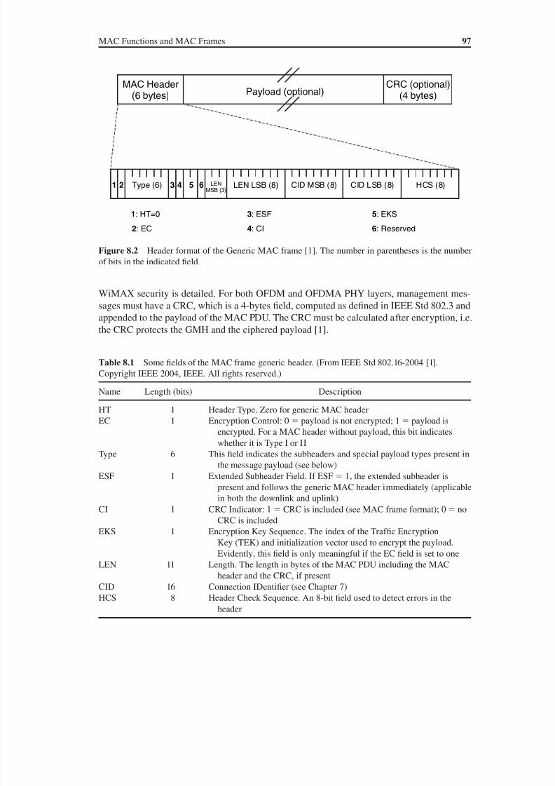
8/10/2019 WiMax-Tech for BBW Access
http://slidepdf.com/reader/full/wimax-tech-for-bbw-access 115/293
MAC Functions and MAC Frames 97
WiMAX security is detailed. For both OFDM and OFDMA PHY layers, management mes-
sages must have a CRC, which is a 4-bytes field, computed as defined in IEEE Std 802.3 and
appended to the payload of the MAC PDU. The CRC must be calculated after encryption, i.e.
the CRC protects the GMH and the ciphered payload [1].
Payload (optional)MAC Header
(6 bytes)CRC (optional)
(4 bytes)
Type (6) LEN LSB (8) CID MSB (8) CID LSB (8) HCS (8)LENMSB (3)
1 2 3 4 5 6
1: HT=0
2: EC
3: ESF
4: CI
5: EKS
6: Reserved
Figure 8.2 Header format of the Generic MAC frame [1]. The number in parentheses is the number
of bits in the indicated field
Table 8.1 Some fields of the MAC frame generic header. (From IEEE Std 802.16-2004 [1].
Copyright IEEE 2004, IEEE. All rights reserved.)
Name Length (bits) Description
HT 1 Header Type. Zero for generic MAC header
EC 1 Encryption Control: 0 payload is not encrypted; 1 payload is
encrypted. For a MAC header without payload, this bit indicates
whether it is Type I or II
Type 6 This field indicates the subheaders and special payload types present in
the message payload (see below)
ESF 1 Extended Subheader Field. If ESF 1, the extended subheader ispresent and follows the generic MAC header immediately (applicable
in both the downlink and uplink)
CI 1 CRC Indicator: 1 CRC is included (see MAC frame format); 0 no
CRC is included
EKS 1 Encryption Key Sequence. The index of the Traffic Encryption
Key (TEK) and initialization vector used to encrypt the payload.
Evidently, this field is only meaningful if the EC field is set to one
LEN 11 Length. The length in bytes of the MAC PDU including the MAC
header and the CRC, if present
CID 16 Connection IDentifier (see Chapter 7)
HCS 8 Header Check Sequence. An 8-bit field used to detect errors in theheader
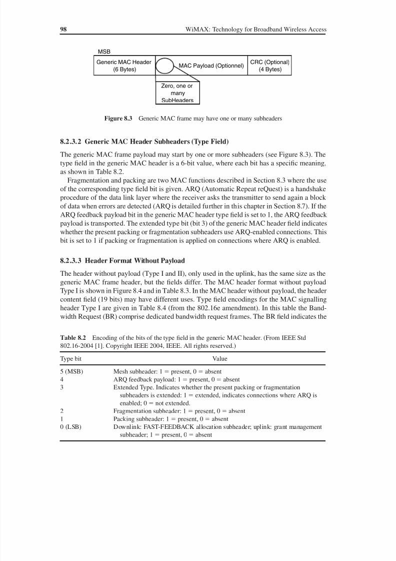
8/10/2019 WiMax-Tech for BBW Access
http://slidepdf.com/reader/full/wimax-tech-for-bbw-access 116/293
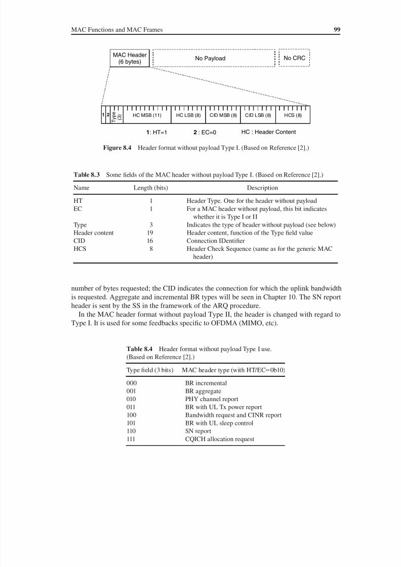
8/10/2019 WiMax-Tech for BBW Access
http://slidepdf.com/reader/full/wimax-tech-for-bbw-access 117/293
MAC Functions and MAC Frames 99
number of bytes requested; the CID indicates the connection for which the uplink bandwidth
is requested. Aggregate and incremental BR types will be seen in Chapter 10. The SN report
header is sent by the SS in the framework of the ARQ procedure.
In the MAC header format without payload Type II, the header is changed with regard to
Type I. It is used for some feedbacks specific to OFDMA (MIMO, etc).
No PayloadMAC Header
(6 bytes)No CRC
e p y T
) 3 (
HC LSB (8) CID MSB (8) CID LSB (8) HCS (8)2
1: HT=1 2 : EC=0
HC MSB (11)
HC : Header Content
1
Figure 8.4 Header format without payload Type I. (Based on Reference [2].)
Table 8.3 Some fields of the MAC header without payload Type I. (Based on Reference [2].)
Name Length (bits) Description
HT 1 Header Type. One for the header without payload
EC 1 For a MAC header without payload, this bit indicates
whether it is Type I or II
Type 3 Indicates the type of header without payload (see below)
Header content 19 Header content, function of the Type field value
CID 16 Connection IDentifier
HCS 8 Header Check Sequence (same as for the generic MAC
header)
Table 8.4 Header format without payload Type I use.
(Based on Reference [2].)
Type field (3 bits) MAC header type (with HT/EC0b10)
000 BR incremental
001 BR aggregate
010 PHY channel report
011 BR with UL Tx power report
100 Bandwidth request and CINR report
101 BR with UL sleep control
110 SN report111 CQICH allocation request
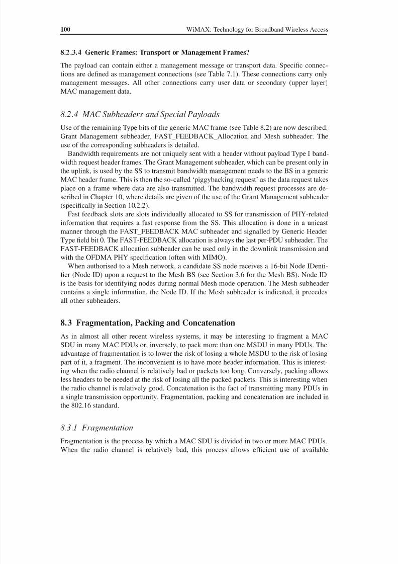
8/10/2019 WiMax-Tech for BBW Access
http://slidepdf.com/reader/full/wimax-tech-for-bbw-access 118/293
100 WiMAX: Technology for Broadband Wireless Access
8.2.3.4 Generic Frames: Transport or Management Frames?
The payload can contain either a management message or transport data. Specific connec-
tions are defined as management connections (see Table 7.1). These connections carry only
management messages. All other connections carry user data or secondary (upper layer)MAC management data.
8.2.4 MAC Subheaders and Special Payloads
Use of the remaining Type bits of the generic MAC frame (see Table 8.2) are now described:
Grant Management subheader, FAST_FEEDBACK_Allocation and Mesh subheader. The
use of the corresponding subheaders is detailed.
Bandwidth requirements are not uniquely sent with a header without payload Type I band-
width request header frames. The Grant Management subheader, which can be present only in
the uplink, is used by the SS to transmit bandwidth management needs to the BS in a genericMAC header frame. This is then the so-called ‘piggybacking request’ as the data request takes
place on a frame where data are also transmitted. The bandwidth request processes are de-
scribed in Chapter 10, where details are given of the use of the Grant Management subheader
(specifically in Section 10.2.2).
Fast feedback slots are slots individually allocated to SS for transmission of PHY-related
information that requires a fast response from the SS. This allocation is done in a unicast
manner through the FAST_FEEDBACK MAC subheader and signalled by Generic Header
Type field bit 0. The FAST-FEEDBACK allocation is always the last per-PDU subheader. The
FAST-FEEDBACK allocation subheader can be used only in the downlink transmission and
with the OFDMA PHY specification (often with MIMO).When authorised to a Mesh network, a candidate SS node receives a 16-bit Node IDenti-
fier (Node ID) upon a request to the Mesh BS (see Section 3.6 for the Mesh BS). Node ID
is the basis for identifying nodes during normal Mesh mode operation. The Mesh subheader
contains a single information, the Node ID. If the Mesh subheader is indicated, it precedes
all other subheaders.
8.3 Fragmentation, Packing and Concatenation
As in almost all other recent wireless systems, it may be interesting to fragment a MAC
SDU in many MAC PDUs or, inversely, to pack more than one MSDU in many PDUs. Theadvantage of fragmentation is to lower the risk of losing a whole MSDU to the risk of losing
part of it, a fragment. The inconvenient is to have more header information. This is interest-
ing when the radio channel is relatively bad or packets too long. Conversely, packing allows
less headers to be needed at the risk of losing all the packed packets. This is interesting when
the radio channel is relatively good. Concatenation is the fact of transmitting many PDUs in
a single transmission opportunity. Fragmentation, packing and concatenation are included in
the 802.16 standard.
8.3.1 FragmentationFragmentation is the process by which a MAC SDU is divided in two or more MAC PDUs.
When the radio channel is relatively bad, this process allows efficient use of available
8/10/2019 WiMax-Tech for BBW Access
http://slidepdf.com/reader/full/wimax-tech-for-bbw-access 119/293
MAC Functions and MAC Frames 101
bandwidth while taking into account the QoS requirements of a connection service flow. The
presence of fragmentation is indicated by bit 2 of the Type field (see Section 8.2) of a generic
MAC frame. Usually, fragmentation concerns relatively long packets (such as IP packets).
Fragmentation of a packet is shown in Figure 8.5.The three MPDUs obtained in the example shown each contain a Fragment subheader.
Thus bit 2 of the Type field in the generic MAC header will be set to 1 (see Section 8.2.3).
The Fragment subheader will contain information such as if the fragment is the first, middle
or last, etc.
The capabilities of fragmentation and reassembly are mandatory.
8.3.2 Packing
When packing is turned on for a connection, the MAC layer may pack multiple MAC SDUs
into one single MAC PDU. When the radio channel is relatively good, this allows a better use
of available resources. The transmitting side has the full decision of whether or not to pack a
group of MAC SDUs in a single MAC PDU. The presence of packing is indicated by bit 1 of
the Type field of the generic MAC frame (see Section 8.2.3).
Packing is especially efficient for relatively short packets. A packed packet is shown in
Figure 8.6. The payload of the frame will contain many packing subheaders, and each one
will be followed by its MAC SDU. The sum of packed headers is smaller than the sum of
headers of normal SDUs. This is why packing saves bandwidth resources. On the other hand,
if the packed PDU is lost, all component SDUs are lost (while possibly only one would have
been lost if packing was not done).
If the ARQ mechanism is turned on, subheaders of fragmentation and packing are extended.
For example, the subheaders of a packed packet are made of 3 bytes instead of 2.
The capability of unpacking is mandatory.
MAC SDU
Fragment #1 Fragment #2 Fragment #3
FragmentSub-Header
(1 or 2bytes)
MAC SDUFragment #1
OptionalCRC
(4 bytes)
MAC SDUFragment #3
FragmentSub-Header
(1 or 2bytes)
GenericMAC
Header (6 bytes)
MPDU #1 MPDU #3Payload
GenericMAC
Header (6 bytes)
OptionalCRC
(4 bytes)
GenericMAC
Header
(6 bytes)
FragmentSub-Header
(1 or 2
bytes)
OptionalCRC
(4 bytes)
MAC SDUFragment #2
MPDU #2
Figure 8.5 Illustration of the fragmentation of an MAC SDU giving three MAC PDUs (or MAC
frames)
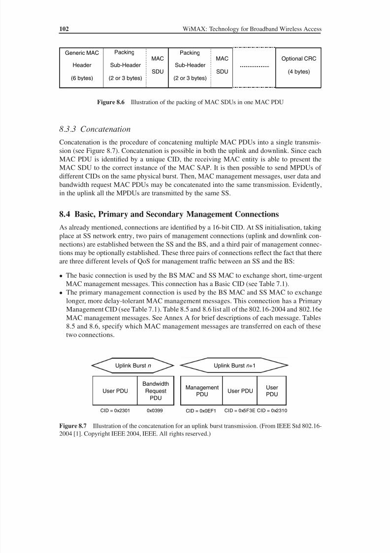
8/10/2019 WiMax-Tech for BBW Access
http://slidepdf.com/reader/full/wimax-tech-for-bbw-access 120/293
102 WiMAX: Technology for Broadband Wireless Access
8.3.3 Concatenation
Concatenation is the procedure of concatening multiple MAC PDUs into a single transmis-
sion (see Figure 8.7). Concatenation is possible in both the uplink and downlink. Since each
MAC PDU is identified by a unique CID, the receiving MAC entity is able to present the
MAC SDU to the correct instance of the MAC SAP. It is then possible to send MPDUs ofdifferent CIDs on the same physical burst. Then, MAC management messages, user data and
bandwidth request MAC PDUs may be concatenated into the same transmission. Evidently,
in the uplink all the MPDUs are transmitted by the same SS.
8.4 Basic, Primary and Secondary Management Connections
As already mentioned, connections are identified by a 16-bit CID. At SS initialisation, taking
place at SS network entry, two pairs of management connections (uplink and downlink con-
nections) are established between the SS and the BS, and a third pair of management connec-
tions may be optionally established. These three pairs of connections reflect the fact that thereare three different levels of QoS for management traffic between an SS and the BS:
• The basic connection is used by the BS MAC and SS MAC to exchange short, time-urgent
MAC management messages. This connection has a Basic CID (see Table 7.1).
• The primary management connection is used by the BS MAC and SS MAC to exchange
longer, more delay-tolerant MAC management messages. This connection has a Primary
Management CID (see Table 7.1). Table 8.5 and 8.6 list all of the 802.16-2004 and 802.16e
MAC management messages. See Annex A for brief descriptions of each message. Tables
8.5 and 8.6, specify which MAC management messages are transferred on each of these
two connections.
Generic MAC
Header
(6 bytes)
Packing
Sub-Header
(2 or 3 bytes)
MAC
SDU
Packing
Sub-Header
(2 or 3 bytes)
MAC
SDU…………….
Optional CRC
(4 bytes)
Figure 8.6 Illustration of the packing of MAC SDUs in one MAC PDU
CID = 0x0EF1
ManagementPDU
User PDUUserPDU
CID = 0x5F3E CID = 0x2310
Uplink Burst n +1
User PDU
Bandwidth
Request
PDU
CID = 0x2301 0x0399
Uplink Burst n
Figure 8.7 Illustration of the concatenation for an uplink burst transmission. (From IEEE Std 802.16-
2004 [1]. Copyright IEEE 2004, IEEE. All rights reserved.)
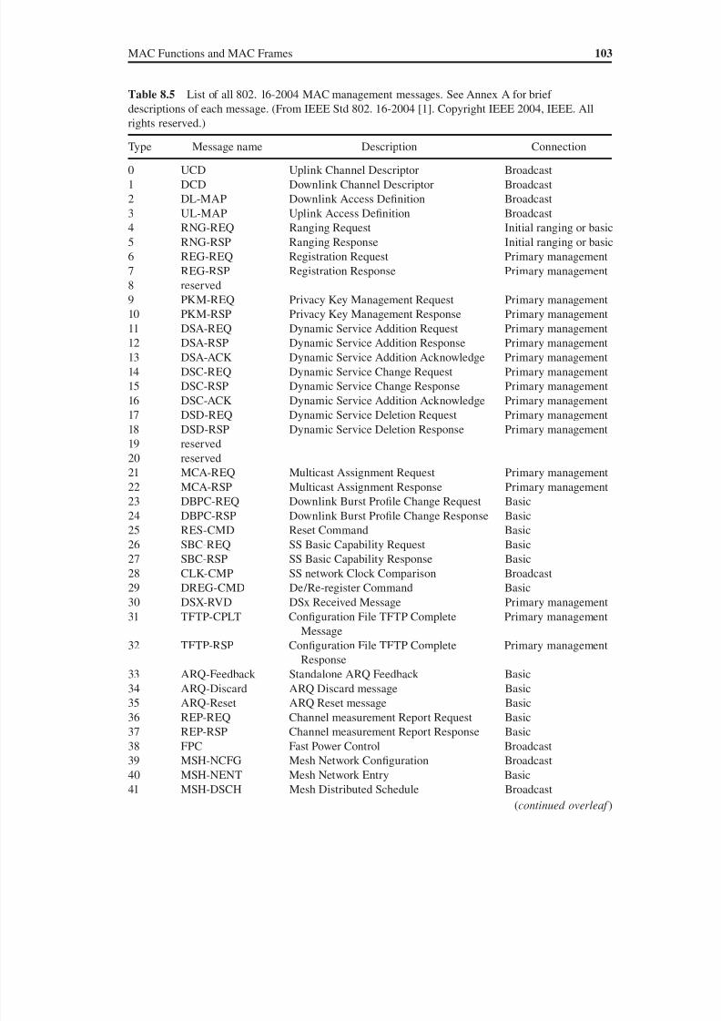
8/10/2019 WiMax-Tech for BBW Access
http://slidepdf.com/reader/full/wimax-tech-for-bbw-access 121/293

8/10/2019 WiMax-Tech for BBW Access
http://slidepdf.com/reader/full/wimax-tech-for-bbw-access 122/293
104 WiMAX: Technology for Broadband Wireless Access
• The secondary management connection is used by the BS and SS to transfer delaytolerant, standards-based messages. These standards are the Dynamic Host Configura-
tion Protocol (DHCP), Trivial File Transfer Protocol (TFTP), Simple Network Manage-
ment Protocol (SNMP), etc. The secondary management messages are carried in IP
datagrams, as mentioned later in Chapter 11 (see also Section 5.2.6 of the standard [1]
for IP CS PDU formats). Hence, secondary management messages are not MAC man-
agement messages. Use of the secondary management connection is required only for
managed SSs.
Table 8.5 (continued )
Type Message name Description Connection
42 MSH-CSCH Mesh Centralised Schedule Broadcast
43 MSH-CSCF Mesh Centralised Schedule Configuration Broadcast44 AAS-FBCK-REQ AAS Feedback Request Basic
45 AAS-FBCK-RSP AAS Feedback Response Basic
46 AAS-Beam_Select AAS Beam Select message Basic
47 AAS-BEAM_REQ AAS Beam Request message Basic
48 AAS-BEAM_RSP AAS Beam Response message Basic
49 DREG-REQ SS De-registration Request message Basic
50–255 reserved
Table 8.6 MAC management messages added by the 802.16e amendment. (From IEEE Std
802.16e-2005 [2]. Copyright IEEE 2006, IEEE. All rights reserved.)
Type Message name Description Connection
50 MOB_SLP-REQ SLeep REQuest Basic
51 MOB_SLP-RSP SLeep ReSPonse Basic
52 MOB_TRF-IND TRaffic INDication Broadcast
53 MOB_NBR-ADV Neighbour ADVertisement Broadcast and primary
management
54 MOB_SCN-REQ SCanning interval allocation REQuest Basic
55 MOB_SCN-RSP SCanning interval allocation ReSPonse Basic
56 MOB_BSHO-REQ BS HO REQuest Basic57 MOB_MSHO-REQ MS HO REQuest Basic
58 MOB_BSHO-RSP BS HO Response Basic
59 MOB_HO-IND HO INDication Basic
60 MOB_SCN-REP Scanning result REPort Primary management
61 MOB_PAG-ADV BS broadcast PAGing Broadcast
62 MBS_MAP MBS MAP —
63 PMC_REQ Power control Mode Change REQuest Basic
64 PMC_RSP Power control Mode Change Response Basic
65 PRC-LT-CTRL Set-up/tear-down of Long-Term MIMO
precoding
Basic
66 MOB_ASC-REP Association result REPort Primary management67–255 reserved
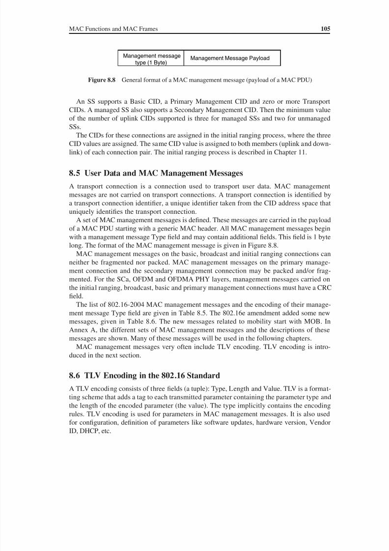
8/10/2019 WiMax-Tech for BBW Access
http://slidepdf.com/reader/full/wimax-tech-for-bbw-access 123/293

8/10/2019 WiMax-Tech for BBW Access
http://slidepdf.com/reader/full/wimax-tech-for-bbw-access 124/293
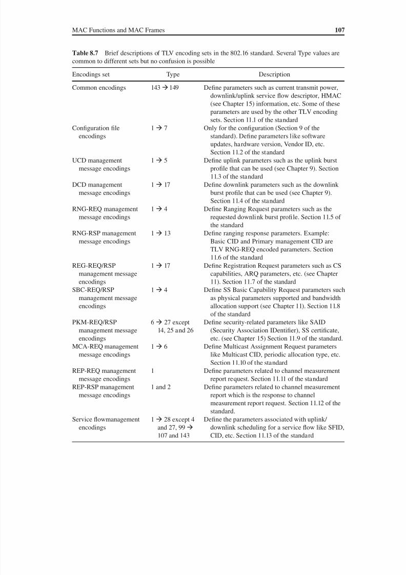
8/10/2019 WiMax-Tech for BBW Access
http://slidepdf.com/reader/full/wimax-tech-for-bbw-access 125/293
MAC Functions and MAC Frames 107
Table 8.7 Brief descriptions of TLV encoding sets in the 802.16 standard. Several Type values are
common to different sets but no confusion is possible
Encodings set Type Description
Common encodings 143 149 Define parameters such as current transmit power,downlink/uplink service flow descriptor, HMAC
(see Chapter 15) information, etc. Some of these
parameters are used by the other TLV encoding
sets. Section 11.1 of the standard
Configuration file
encodings
1 7 Only for the configuration (Section 9 of the
standard). Define parameters like software
updates, hardware version, Vendor ID, etc.
Section 11.2 of the standard
UCD management
message encodings
1 5 Define uplink parameters such as the uplink burst
profile that can be used (see Chapter 9). Section
11.3 of the standardDCD management
message encodings
1 17 Define downlink parameters such as the downlink
burst profile that can be used (see Chapter 9).
Section 11.4 of the standard
RNG-REQ management
message encodings
1 4 Define Ranging Request parameters such as the
requested downlink burst profile. Section 11.5 of
the standard
RNG-RSP management
message encodings
1 13 Define ranging response parameters. Example:
Basic CID and Primary management CID are
TLV RNG-REQ encoded parameters. Section
11.6 of the standard
REG-REQ/RSP
management message
encodings
1 17 Define Registration Request parameters such as CS
capabilities, ARQ parameters, etc. (see Chapter
11). Section 11.7 of the standard
SBC-REQ/RSP
management message
encodings
1 4 Define SS Basic Capability Request parameters such
as physical parameters supported and bandwidth
allocation support (see Chapter 11). Section 11.8
of the standard
PKM-REQ/RSP
management message
encodings
6 27 except
14, 25 and 26
Define security-related parameters like SAID
(Security Association IDentifier), SS certificate,
etc. (see Chapter 15) Section 11.9 of the standard.
MCA-REQ managementmessage encodings 1
6 Define Multicast Assignment Request parameterslike Multicast CID, periodic allocation type, etc.
Section 11.10 of the standard
REP-REQ management
message encodings
1 Define parameters related to channel measurement
report request. Section 11.11 of the standard
REP-RSP management
message encodings
1 and 2 Define parameters related to channel measurement
report which is the response to channel
measurement report request. Section 11.12 of the
standard.
Service flowmanagement
encodings
1 28 except 4
and 27, 99
107 and 143
Define the parameters associated with uplink/
downlink scheduling for a service flow like SFID,
CID, etc. Section 11.13 of the standard
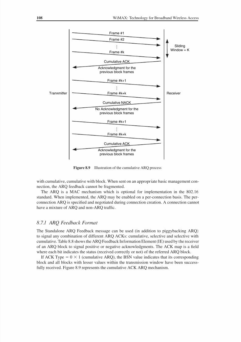
8/10/2019 WiMax-Tech for BBW Access
http://slidepdf.com/reader/full/wimax-tech-for-bbw-access 126/293
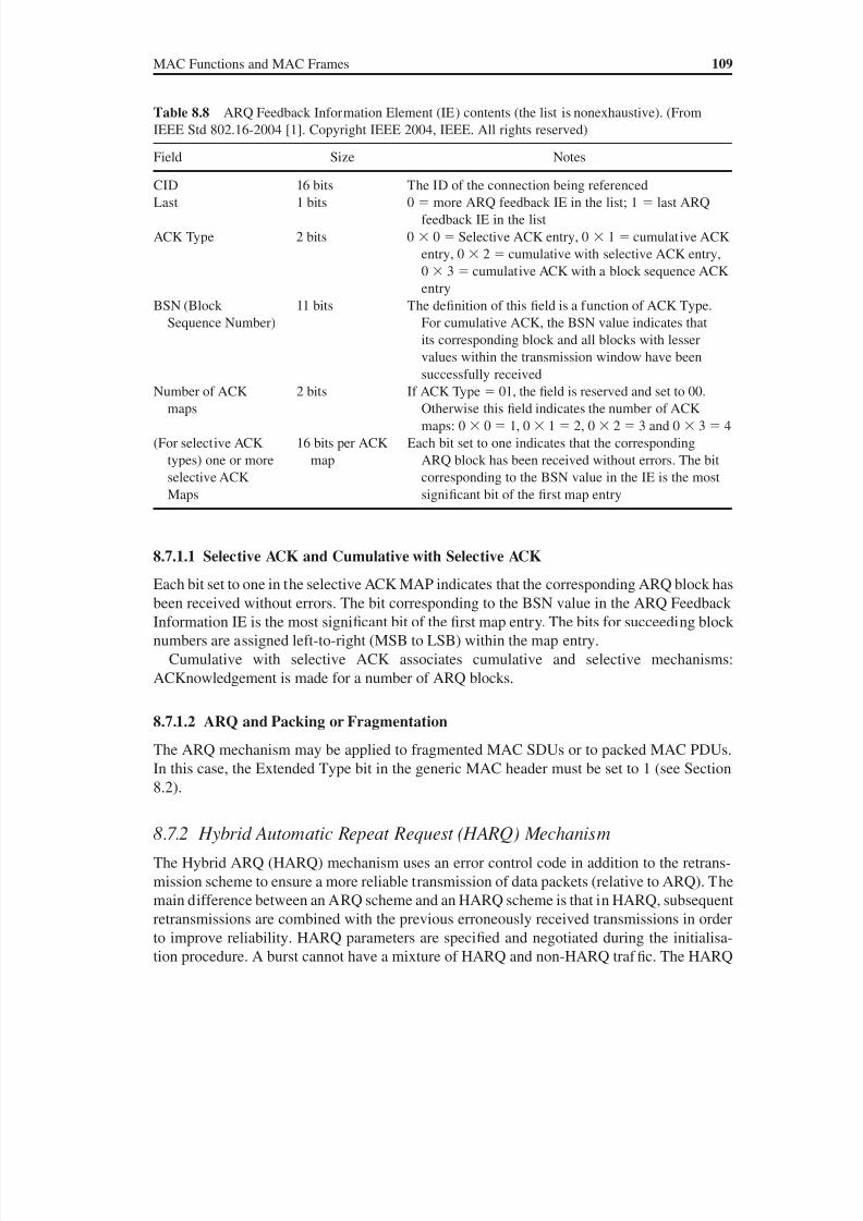
8/10/2019 WiMax-Tech for BBW Access
http://slidepdf.com/reader/full/wimax-tech-for-bbw-access 127/293
MAC Functions and MAC Frames 109
8.7.1.1 Selective ACK and Cumulative with Selective ACK
Each bit set to one in the selective ACK MAP indicates that the corresponding ARQ block has
been received without errors. The bit corresponding to the BSN value in the ARQ Feedback
Information IE is the most significant bit of the first map entry. The bits for succeeding block
numbers are assigned left-to-right (MSB to LSB) within the map entry.
Cumulative with selective ACK associates cumulative and selective mechanisms:
ACKnowledgement is made for a number of ARQ blocks.
8.7.1.2 ARQ and Packing or Fragmentation
The ARQ mechanism may be applied to fragmented MAC SDUs or to packed MAC PDUs.
In this case, the Extended Type bit in the generic MAC header must be set to 1 (see Section
8.2).
8.7.2 Hybrid Automatic Repeat Request (HARQ) Mechanism
The Hybrid ARQ (HARQ) mechanism uses an error control code in addition to the retrans-
mission scheme to ensure a more reliable transmission of data packets (relative to ARQ). The
main difference between an ARQ scheme and an HARQ scheme is that in HARQ, subsequent
retransmissions are combined with the previous erroneously received transmissions in order
to improve reliability. HARQ parameters are specified and negotiated during the initialisa-
tion procedure. A burst cannot have a mixture of HARQ and non-HARQ traf fic. The HARQ
Table 8.8 ARQ Feedback Information Element (IE) contents (the list is nonexhaustive). (From
IEEE Std 802.16-2004 [1]. Copyright IEEE 2004, IEEE. All rights reserved)
Field Size Notes
CID 16 bits The ID of the connection being referencedLast 1 bits 0 more ARQ feedback IE in the list; 1 last ARQ
feedback IE in the list
ACK Type 2 bits 0 0 Selective ACK entry, 0 1 cumulative ACK
entry, 0 2 cumulative with selective ACK entry,
0 3 cumulative ACK with a block sequence ACK
entry
BSN (Block
Sequence Number)
11 bits The definition of this field is a function of ACK Type.
For cumulative ACK, the BSN value indicates that
its corresponding block and all blocks with lesser
values within the transmission window have been
successfully receivedNumber of ACK
maps
2 bits If ACK Type 01, the field is reserved and set to 00.
Otherwise this field indicates the number of ACK
maps: 0 0 1, 0 1 2, 0 2 3 and 0 3 4
(For selective ACK
types) one or more
selective ACK
Maps
16 bits per ACK
map
Each bit set to one indicates that the corresponding
ARQ block has been received without errors. The bit
corresponding to the BSN value in the IE is the most
significant bit of the first map entry
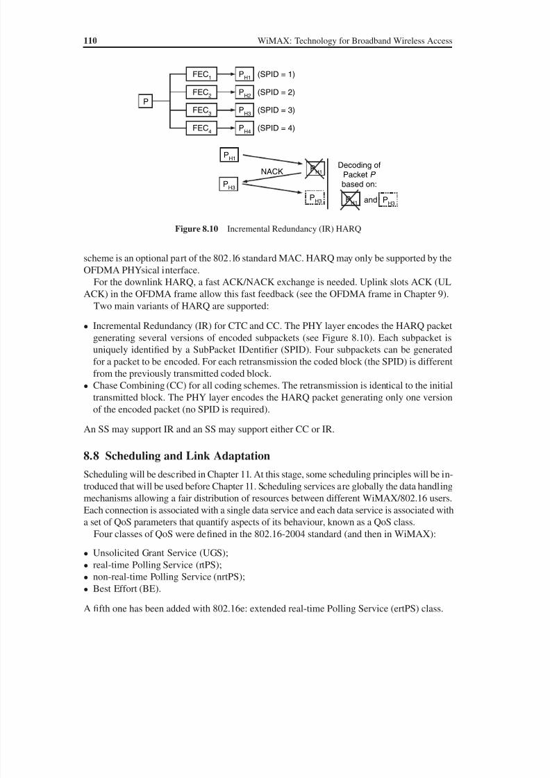
8/10/2019 WiMax-Tech for BBW Access
http://slidepdf.com/reader/full/wimax-tech-for-bbw-access 128/293
110 WiMAX: Technology for Broadband Wireless Access
scheme is an optional part of the 802.16 standard MAC. HARQ may only be supported by the
OFDMA PHYsical interface.
For the downlink HARQ, a fast ACK/NACK exchange is needed. Uplink slots ACK (UL
ACK) in the OFDMA frame allow this fast feedback (see the OFDMA frame in Chapter 9).
Two main variants of HARQ are supported:
• Incremental Redundancy (IR) for CTC and CC. The PHY layer encodes the HARQ packet
generating several versions of encoded subpackets (see Figure 8.10). Each subpacket is
uniquely identified by a SubPacket IDentifier (SPID). Four subpackets can be generatedfor a packet to be encoded. For each retransmission the coded block (the SPID) is different
from the previously transmitted coded block.
• Chase Combining (CC) for all coding schemes. The retransmission is identical to the initial
transmitted block. The PHY layer encodes the HARQ packet generating only one version
of the encoded packet (no SPID is required).
An SS may support IR and an SS may support either CC or IR.
8.8 Scheduling and Link Adaptation
Scheduling will be described in Chapter 11. At this stage, some scheduling principles will be in-troduced that will be used before Chapter 11. Scheduling services are globally the data handling
mechanisms allowing a fair distribution of resources between different WiMAX/802.16 users.
Each connection is associated with a single data service and each data service is associated with
a set of QoS parameters that quantify aspects of its behaviour, known as a QoS class.
Four classes of QoS were defined in the 802.16-2004 standard (and then in WiMAX):
• Unsolicited Grant Service (UGS);
• real-time Polling Service (rtPS);
• non-real-time Polling Service (nrtPS);
• Best Effort (BE).
A fifth one has been added with 802.16e: extended real-time Polling Service (ertPS) class.
and
NACK
P
FEC1
PH1
(SPID = 1)
FEC2
PH2
(SPID = 2)
FEC3
PH3
(SPID = 3)
FEC4
PH4
(SPID = 4)
PH1
PH1
PH3
PH3
Decoding ofPacket P based on:
PH1 P
H3
Figure 8.10 Incremental Redundancy (IR) HARQ
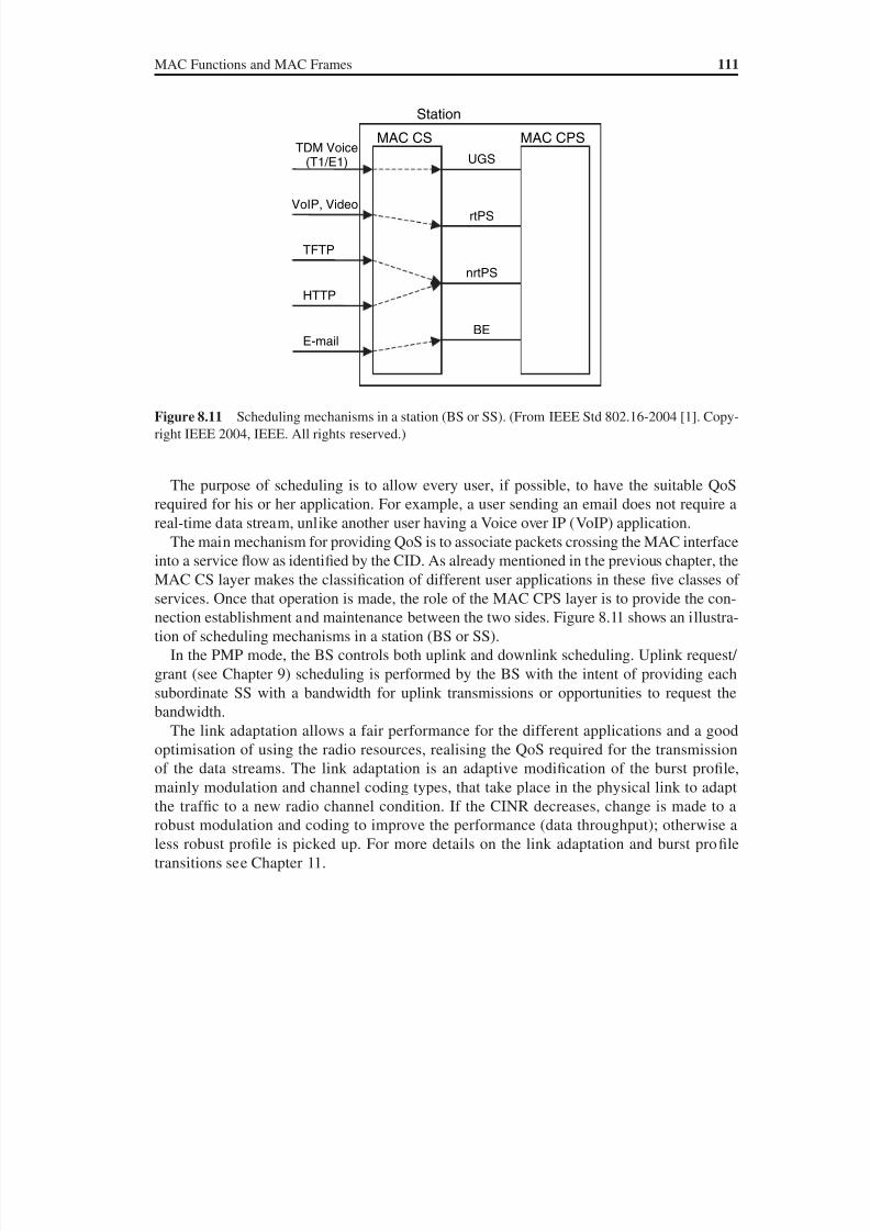
8/10/2019 WiMax-Tech for BBW Access
http://slidepdf.com/reader/full/wimax-tech-for-bbw-access 129/293

8/10/2019 WiMax-Tech for BBW Access
http://slidepdf.com/reader/full/wimax-tech-for-bbw-access 130/293
9Multiple Access and BurstProfile Description
9.1 Introduction
The aim of this chapter is to describe the multiple access of WiMAX/802.16. It will be seen
that the mechanisms of multiple access and radio resource sharing are rather complex. It
can be said that they are more complex than in other known wireless systems such as GSM,
WiFi/IEEE 802.11 or even UMTS. Yet, globally, WiMAX multiple access is an extremely
flexible F/TDMA (Frequency and Time Division Multiple Access).
The concept of a service flow on a connection is central to the operation of the MAC
protocol. Service flows in the 802.16 standard provide a mechanism for QoS management in
both the uplink and downlink. Service flows are integral to the bandwidth allocation process.
In this process, an SS requests an uplink bandwidth on a per-connection basis (implicitly
identifying the service flow). Bandwidth is granted by the BS to an SS in response to per-
connection requests from the SS. WiMAX has been called a Demand Assigned Multiple
Access (DAMA) system.
First, duplexing possibilities are described in Section 9.2. Physical frames are described in
Section 9.3. WiMAX transmissions take place on totally dynamic bursts. The concept of mul-
tiple access is tightly related to burst profile. Frame contents are indicated in DL-MAP and
UL-MAP messages, described in Section 9.4. The concept of a burst in the 802.16 standard
and the way burst profiles are announced by the BS are detailed in Section 9.5. The specific
case of the Mesh mode is tackled in Section 9.6.
9.2 Duplexing: Both FDD and TDD are Possible
The WiMAX/802.16 standard includes the two main duplexing techniques: Time Division
Duplexing (TDD) and Frequency Division Duplexing (FDD). The choice of one duplexing
technique or the other may affect certain PHY parameters as well as impact on the features
that can be supported. Next, each of these duplexing techniques will be discussed.
WiMAX: Technology for Broadband Wireless Access Loutfi Nuaymi
© 2007 John Wiley & Sons, Ltd. ISBN: 0-470-02808-4

8/10/2019 WiMax-Tech for BBW Access
http://slidepdf.com/reader/full/wimax-tech-for-bbw-access 131/293

8/10/2019 WiMax-Tech for BBW Access
http://slidepdf.com/reader/full/wimax-tech-for-bbw-access 132/293
Multiple Access and Burst Profile Description 115
Comparing the two modes, a fixed duration frame is used for both uplink and downlink
transmissions in FDD while the TDD distribution is adaptive. Therefore TDD duplexing is
more suitable when data rates are asymmetrical (between the uplink and downlink), e.g. for
an Internet transmission.
After settling the question of duplexing, many users have to share the bandwidth resource
in each kind of transmission.
9.3 Transmission of Downlink and Uplink Subframes
Downlink and uplink transmissions coexist according to one of the two duplexing modes:
TDD or FDD. They are sent through the downlink and uplink subframes. More specific
Frame j-2 Frame j-1 Frame j Frame j+1 Frame j+2
Downlink Subframe Uplink Subframe
AdaptivePS 0 PS n-1
……
Figure 9.2 TDD frame: uplink and downlink transmissions share the same frequency but have dif-
ferent transmission times. (From IEEE Std 802.16-2004 [1]. Copyright IEEE 2004, IEEE. All rightsreserved.)
Figure 9.3 General format of a TDD frame (OFDM PHY). (Based on Reference [1].) In the FDD
mode, the downlink subframe and uplink subframes are transmitted on two separate frequencies as the
uplink frame and downlink frame. The contents are the same for FDD and TDD.
Frame n+2Frame n+1Frame nFrame n-1
DL-PHY PDU
Contention
Slot for Initial
Ranging
Contention Slot
for BW
Requests
UL-PHY PDU
from SS #1....
UL-PHY PDU
from SS #k
UL subframeDL Subframe
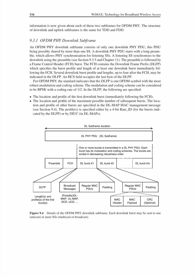
8/10/2019 WiMax-Tech for BBW Access
http://slidepdf.com/reader/full/wimax-tech-for-bbw-access 133/293
116 WiMAX: Technology for Broadband Wireless Access
information is now given about each of these two subframes for OFDM PHY. The structure
of downlink and uplink subframes is the same for TDD and FDD.
9.3.1 OFDM PHY Downlink SubframeAn OFDM PHY downlink subframe consists of only one downlink PHY PDU, this PDU
being possibly shared by more than one SS. A downlink PHY PDU starts with a long pream-
ble, which allows PHY synchronisation for listening SSs. A listening SS synchronises to the
downlink using the preamble (see Section 9.3.5 and Chapter 11). The preamble is followed by
a Frame Control Header (FCH) burst. The FCH contains the Downlink Frame Prefix (DLFP)
which specifies the burst profile and length of at least one downlink burst immediately fol-
lowing the FCH. Several downlink burst profile and lengths, up to four after the FCH, may be
indicated in the DLFP. An HCS field occupies the last byte of the DLFP.
For OFDM PHY, the standard indicates that the DLFP is one OFDM symbol with the most
robust modulation and coding scheme. The modulation and coding scheme can be considered
to be BPSK with a coding rate of 1/2. In the DLFP, the following are specified:
• The location and profile of the first downlink burst (immediately following the FCH).
• The location and profile of the maximum possible number of subsequent bursts. The loca-
tion and profile of other bursts are specified in the DL-MAP MAC management message
(see Section 9.4). The profile(s) is specified either by a 4-bit Rate_ID (for the bursts indi-
cated by the DLFP) or by DIUC (in DL-MAPs).
Figure 9.4 Details of the OFDM PHY downlink subframe. Each downlink burst may be sent to one
(unicast) or more SSs (multicast or broadcast).
Length(s) and
profile(s) of the first
burst(s)
DL PHY PDU (DL Subframe)
One or more bursts is transmitted in a DL PHY PDU. Each
burst has its modulation and coding schemes. The bursts are
sorted in decreasing robustness order.
DL Subframe duration
DL burst #mDL burst #2DL burst #1Preamble FCH
DLFPRegular MAC
PDUs
Broadcast
MessagesPadding
Regular MAC
PDUsPadding
MAC
Payload
MAC
Header
CRC
(Optional)
(Possibly)DL-
MAP, UL-MAP,
DCD, UCD, ...
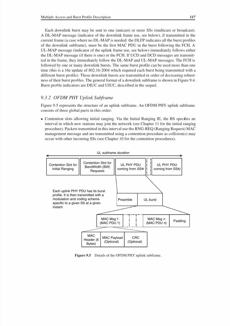
8/10/2019 WiMax-Tech for BBW Access
http://slidepdf.com/reader/full/wimax-tech-for-bbw-access 134/293
Multiple Access and Burst Profile Description 117
Each downlink burst may be sent to one (unicast) or more SSs (multicast or broadcast).
A DL-MAP message (indicator of the downlink frame use, see below), if transmitted in the
current frame (a case where no DL-MAP is needed: the DLFP indicates all the burst profiles
of the downlink subframe), must be the first MAC PDU in the burst following the FCH. A
UL-MAP message (indicator of the uplink frame use, see below) immediately follows eitherthe DL-MAP message (if there is one) or the FCH. If UCD and DCD messages are transmit-
ted in the frame, they immediately follow the DL-MAP and UL-MAP messages. The FCH is
followed by one or many downlink bursts. The same burst profile can be used more than one
time (this is a 16e update of 802.16-2004 which required each burst being transmitted with a
different burst profile). These downlink bursts are transmitted in order of decreasing robust-
ness of their burst profiles. The general format of a downlink subframe is shown in Figure 9.4.
Burst profile indicators are DIUC and UIUC, described in the sequel.
9.3.2 OFDM PHY Uplink SubframeFigure 9.5 represents the structure of an uplink subframe. An OFDM PHY uplink subframe
consists of three global parts in this order:
• Contention slots allowing initial ranging. Via the Initial Ranging IE, the BS specifies an
interval in which new stations may join the network (see Chapter 11 for the initial ranging
procedure). Packets transmitted in this interval use the RNG-REQ (Ranging Request) MAC
management message and are transmitted using a contention procedure as collision(s) may
occur with other incoming SSs (see Chapter 10 for the contention procedures).
Figure 9.5 Details of the OFDM PHY uplink subframe.
UL PHY PDUcoming from SS# j
UL subframe duration
Preamble UL burst
Each uplink PHY PDU has its burstprofile. It is then transmitted with a
modulation and coding schemespecific to a given SS at a giveninstant
Padding
MAC Payload(Optional)
MACHeader (6
Bytes)
CRC(Optional)
UL PHY PDUcoming from SS#i
Contention Slot forInitial Ranging
Contention Slot forBandWidth (BW)
Requests
MAC Msg 1(MAC PDU 1)
MAC Msg n
(MAC PDU n )
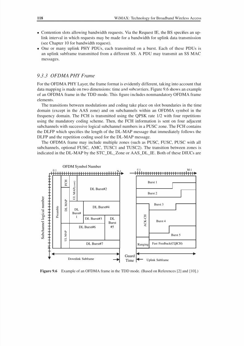
8/10/2019 WiMax-Tech for BBW Access
http://slidepdf.com/reader/full/wimax-tech-for-bbw-access 135/293
118 WiMAX: Technology for Broadband Wireless Access
• Contention slots allowing bandwidth requests. Via the Request IE, the BS specifies an up-
link interval in which requests may be made for a bandwidth for uplink data transmission
(see Chapter 10 for bandwidth request).
• One or many uplink PHY PDUs, each transmitted on a burst. Each of these PDUs is
an uplink subframe transmitted from a different SS. A PDU may transmit an SS MACmessages.
9.3.3 OFDMA PHY Frame
For the OFDMA PHY Layer, the frame format is evidently different, taking into account that
data mapping is made on two dimensions: time and subcarriers. Figure 9.6 shows an example
of an OFDMA frame in the TDD mode. This figure includes nonmandatory OFDMA frame
elements.
The transitions between modulations and coding take place on slot boundaries in the timedomain (except in the AAS zone) and on subchannels within an OFDMA symbol in the
frequency domain. The FCH is transmitted using the QPSK rate 1/2 with four repetitions
using the mandatory coding scheme. Then, the FCH information is sent on four adjacent
subchannels with successive logical subchannel numbers in a PUSC zone. The FCH contains
the DLFP which specifies the length of the DL-MAP message that immediately follows the
DLFP and the repetition coding used for the DL-MAP message.
The OFDMA frame may include multiple zones (such as PUSC, FUSC, PUSC with all
subchannels, optional FUSC, AMC, TUSC1 and TUSC2). The transition between zones is
indicated in the DL-MAP by the STC_DL_Zone or AAS_DL_IE. Both of these DIUCs are
Figure 9.6 Example of an OFDMA frame in the TDD mode. (Based on References [2] and [10].)
e l b m a e r P
H C F
P A M L
D
P A M L U
P A M L U
(
t n o c
)
DL Burst#2
DLBurst#
1
DL Burst#4
DL Burst#6
DL Burst#3 DL
Burst
#5
DL Burst#7
OFDM Symbol Number
S u b c h a n n e l l o g i c a l
n u m b e r
1
N
10 N-1
Downlink Subframe
Ranging
A C K - C H
Fast Feedback(CQICH)
Burst 1
Burst 2
Burst 3
Burst 4
Burst 5
Uplink Subframe
Guard
Time
10 M-1
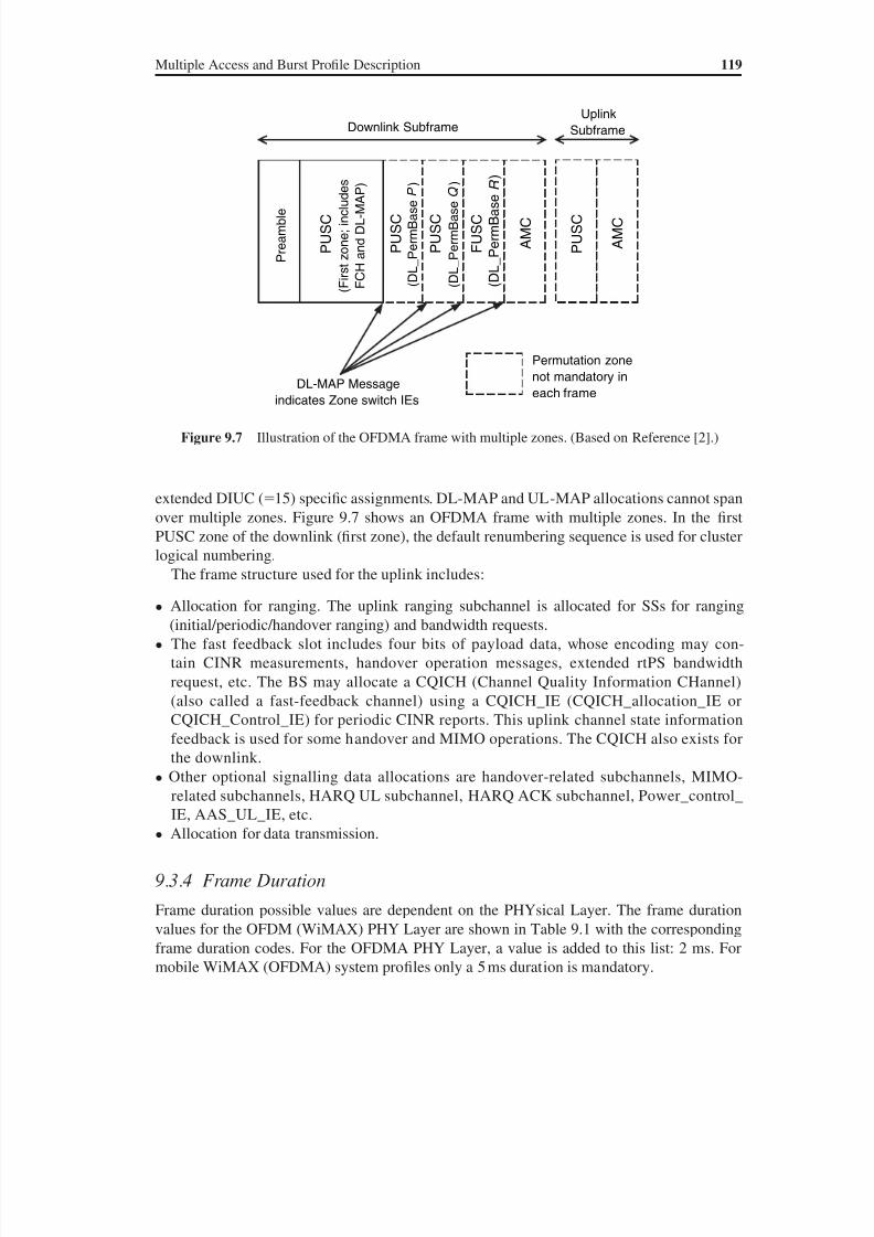
8/10/2019 WiMax-Tech for BBW Access
http://slidepdf.com/reader/full/wimax-tech-for-bbw-access 136/293
Multiple Access and Burst Profile Description 119
extended DIUC (15) specific assignments. DL-MAP and UL-MAP allocations cannot span
over multiple zones. Figure 9.7 shows an OFDMA frame with multiple zones. In the first
PUSC zone of the downlink (first zone), the default renumbering sequence is used for cluster
logical numbering.
The frame structure used for the uplink includes:
• Allocation for ranging. The uplink ranging subchannel is allocated for SSs for ranging
(initial/periodic/handover ranging) and bandwidth requests.
• The fast feedback slot includes four bits of payload data, whose encoding may con-
tain CINR measurements, handover operation messages, extended rtPS bandwidth
request, etc. The BS may allocate a CQICH (Channel Quality Information CHannel)
(also called a fast-feedback channel) using a CQICH_IE (CQICH_allocation_IE or
CQICH_Control_IE) for periodic CINR reports. This uplink channel state information
feedback is used for some handover and MIMO operations. The CQICH also exists for
the downlink.
• Other optional signalling data allocations are handover-related subchannels, MIMO-
related subchannels, HARQ UL subchannel, HARQ ACK subchannel, Power_control_
IE, AAS_UL_IE, etc.
• Allocation for data transmission.
9.3.4 Frame Duration
Frame duration possible values are dependent on the PHYsical Layer. The frame duration
values for the OFDM (WiMAX) PHY Layer are shown in Table 9.1 with the corresponding
frame duration codes. For the OFDMA PHY Layer, a value is added to this list: 2 ms. For
mobile WiMAX (OFDMA) system profiles only a 5 ms duration is mandatory.
Figure 9.7 Illustration of the OFDMA frame with multiple zones. (Based on Reference [2].)
Downlink Subframe
P r e a m b l e
P U S C
( D L
_ P e r m B a s e P )
P U S C
( D L
_ P e r m B a s e Q )
F U S C
( D L
_ P e r m
B a s e R
)
A M C
P U S C
( F i r s t z o n e ; i n c l u d e s
F C H
a n d D L - M A P )
Uplink
Subframe
P U S C
A M C
DL-MAP Message
indicates Zone switch IEs
Permutation zone
not mandatory ineach frame

8/10/2019 WiMax-Tech for BBW Access
http://slidepdf.com/reader/full/wimax-tech-for-bbw-access 137/293
120 WiMAX: Technology for Broadband Wireless Access
The frame duration is decided by the BS. This value is transmitted in the DCD message onthe frame duration code (on 8 bits), as seen in Section 9.5.2 and Annex B. For the two duplex-
ing systems, the rule is the following:
• In an FDD system, the uplink and downlink channels are located on separate frequencies. A
fixed duration frame is used for both uplink and downlink transmissions.
• In the case of TDD, the uplink and downlink transmissions occur at different (complemen-
tary) times while sharing the same frequency. A TDD frame contains one downlink and one
uplink subframe. The general format of an OFDM PHY TDD frame is shown in Figure 9.3.
For OFDMA PHY, the format is evidently different, taking into account the two dimen-
sions: time and subcarriers (see Figure 9.6).
We now describe the preambles used in 802.16.
9.3.5 Preambles
A 802.16 preamble is a standard-defined sequence of symbols known by the receiver. The
preamble is used by the PHYsical Layer for synchronisation and equalisation. The preamble
must be taken into account for precise computation of a useful data rate.
For the OFDM PHY Layer, all preambles are structured as either one (short preamble) or
two (long preamble) OFDM symbols. The OFDM symbols are defined by the values of the
composing subcarriers. The Cyclic Prefix (CP) of those OFDM symbols has the same length
as the CP of data OFDM symbols.
The long preamble is used in the following cases:
• the first preamble in the downlink PHY PDU;
• the initial ranging preamble;
• the AAS preamble.
The short preamble is used in the following cases:
• the first preamble in the uplink PHY PDU, when no subchannelisation is applied;
• in the downlink bursts that fall within the STC-encoded region, the preamble transmitted
from both transmit antennas simultaneously;
• a burst preamble on the downlink bursts when indicated in the DL-MAP_IE.
Table 9.1 Frame duration possible values for OFDM
(WiMAX) PHY Interface (based on [1])
Frame duration code Frame duration (ms)
0 2.51 4
2 5
3 8
4 10
5 12.5
6 20
7–255 reserved
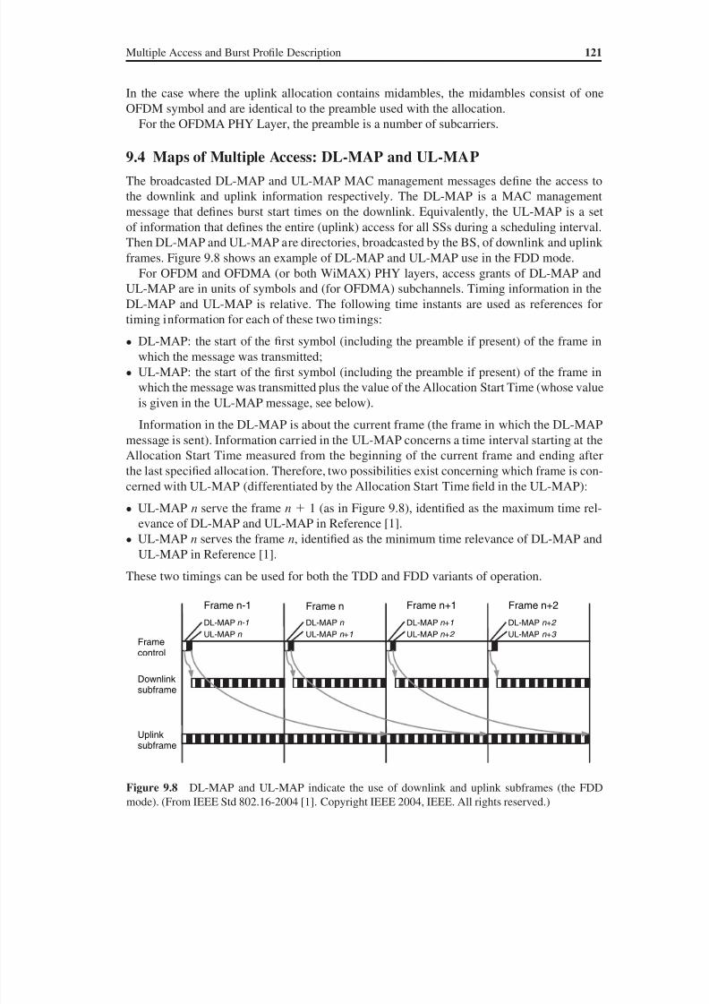
8/10/2019 WiMax-Tech for BBW Access
http://slidepdf.com/reader/full/wimax-tech-for-bbw-access 138/293
Multiple Access and Burst Profile Description 121
In the case where the uplink allocation contains midambles, the midambles consist of one
OFDM symbol and are identical to the preamble used with the allocation.
For the OFDMA PHY Layer, the preamble is a number of subcarriers.
9.4 Maps of Multiple Access: DL-MAP and UL-MAP
The broadcasted DL-MAP and UL-MAP MAC management messages define the access to
the downlink and uplink information respectively. The DL-MAP is a MAC management
message that defines burst start times on the downlink. Equivalently, the UL-MAP is a set
of information that defines the entire (uplink) access for all SSs during a scheduling interval.
Then DL-MAP and UL-MAP are directories, broadcasted by the BS, of downlink and uplink
frames. Figure 9.8 shows an example of DL-MAP and UL-MAP use in the FDD mode.
For OFDM and OFDMA (or both WiMAX) PHY layers, access grants of DL-MAP and
UL-MAP are in units of symbols and (for OFDMA) subchannels. Timing information in the
DL-MAP and UL-MAP is relative. The following time instants are used as references fortiming information for each of these two timings:
• DL-MAP: the start of the first symbol (including the preamble if present) of the frame in
which the message was transmitted;
• UL-MAP: the start of the first symbol (including the preamble if present) of the frame in
which the message was transmitted plus the value of the Allocation Start Time (whose value
is given in the UL-MAP message, see below).
Information in the DL-MAP is about the current frame (the frame in which the DL-MAP
message is sent). Information carried in the UL-MAP concerns a time interval starting at the
Allocation Start Time measured from the beginning of the current frame and ending afterthe last specified allocation. Therefore, two possibilities exist concerning which frame is con-
cerned with UL-MAP (differentiated by the Allocation Start Time field in the UL-MAP):
• UL-MAP n serve the frame n 1 (as in Figure 9.8), identified as the maximum time rel-
evance of DL-MAP and UL-MAP in Reference [1].
• UL-MAP n serves the frame n, identified as the minimum time relevance of DL-MAP and
UL-MAP in Reference [1].
These two timings can be used for both the TDD and FDD variants of operation.
Figure 9.8 DL-MAP and UL-MAP indicate the use of downlink and uplink subframes (the FDD
mode). (From IEEE Std 802.16-2004 [1]. Copyright IEEE 2004, IEEE. All rights reserved.)
Frame n+2Frame n+1Frame nFrame n-1DL-MAP n-1
UL-MAP n
DL-MAP n
UL-MAP n +1
DL-MAP n +1 DL-MAP n +2
UL-MAP n +2 UL-MAP n +3 Framecontrol
Downlinksubframe
Uplinksubframe
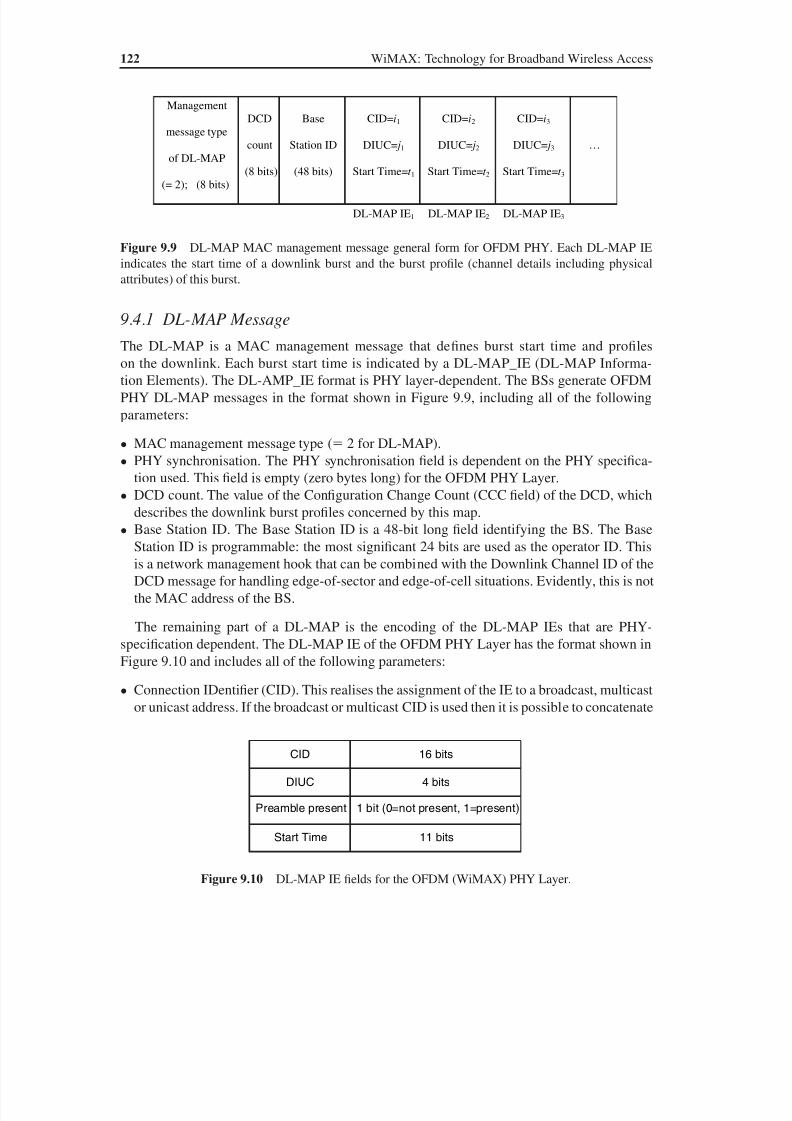
8/10/2019 WiMax-Tech for BBW Access
http://slidepdf.com/reader/full/wimax-tech-for-bbw-access 139/293
122 WiMAX: Technology for Broadband Wireless Access
9.4.1 DL-MAP Message
The DL-MAP is a MAC management message that defines burst start time and profiles
on the downlink. Each burst start time is indicated by a DL-MAP_IE (DL-MAP Informa-
tion Elements). The DL-AMP_IE format is PHY layer-dependent. The BSs generate OFDM
PHY DL-MAP messages in the format shown in Figure 9.9, including all of the following
parameters:
• MAC management message type ( 2 for DL-MAP).
• PHY synchronisation. The PHY synchronisation field is dependent on the PHY specifica-
tion used. This field is empty (zero bytes long) for the OFDM PHY Layer.
• DCD count. The value of the Configuration Change Count (CCC field) of the DCD, which
describes the downlink burst profiles concerned by this map.• Base Station ID. The Base Station ID is a 48-bit long field identifying the BS. The Base
Station ID is programmable: the most significant 24 bits are used as the operator ID. This
is a network management hook that can be combined with the Downlink Channel ID of the
DCD message for handling edge-of-sector and edge-of-cell situations. Evidently, this is not
the MAC address of the BS.
The remaining part of a DL-MAP is the encoding of the DL-MAP IEs that are PHY-
specification dependent. The DL-MAP IE of the OFDM PHY Layer has the format shown in
Figure 9.10 and includes all of the following parameters:
• Connection IDentifier (CID). This realises the assignment of the IE to a broadcast, multicast
or unicast address. If the broadcast or multicast CID is used then it is possible to concatenate
Figure 9.9 DL-MAP MAC management message general form for OFDM PHY. Each DL-MAP IE
indicates the start time of a downlink burst and the burst profile (channel details including physical
attributes) of this burst.
Management
message type
of DL-MAP
(= 2); (8 bits)
DCD
count
(8 bits)
Base
Station ID
(48 bits)
CID=i1
DIUC= j 1
Start Time=t 1
CID=i2
DIUC= j 2
Start Time=t 2
CID=i3
DIUC= j 3
Start Time=t 3
…
DL-MAP IE1 DL-MAP IE2 DL-MAP IE3
Figure 9.10 DL-MAP IE fields for the OFDM (WiMAX) PHY Layer.
CID 16 bits
DIUC 4 bits
Preamble present 1 bit (0=not present, 1=present)
Start Time 11 bits

8/10/2019 WiMax-Tech for BBW Access
http://slidepdf.com/reader/full/wimax-tech-for-bbw-access 140/293
Multiple Access and Burst Profile Description 123
unicast MAC PDUs (with different CIDs) into a single downlink burst. During a broadcast
or multicast downlink burst, it is the responsibility of the BS to ensure that any MAC PDUs
sent to an H-FDD SS do not overlap any uplink allocations for that SS. An H-FDD SS for
which a DL-MAP_IE and UL-MAP_IE overlap in time uses the uplink allocation and dis-
cards downlink traf fic during the overlapping period.
• DIUC. The 4-bit DIUC defines the burst type associated with that burst time interval. Burst
profile descriptions are part of the DCD message for each DIUC used in the DL-MAP
except those associated with Gap, End of Map and Extended (see DIUC in Section 9.5
below).
• Preamble present. If set, the indicated burst will start with the short preamble (see above for
preambles). In the downlink, a short preamble can be optionally inserted at the beginning
of a downlink burst in addition to the long preamble that exists by default at the beginning
of the frame.
• Start Time. This indicates the start time, in units of OFDM symbol duration, relative to the
start of the first symbol of the PHY PDU (including the preamble) where the DL-MAP mes-sage is transmitted. The time instant indicated by the Start Time value is the transmission
times of the first symbol of the burst including the preamble (if present). The end of the
last allocated burst is indicated by allocating an End of Map burst (DIUC 14) with zero
duration (see the DIUC part in Section 9.5.5).
If the length of the DL-MAP message is a nonintegral number of bytes, the LEN field in
the MAC header is rounded up to the next integral number of bytes. The message is padded
to match this length, but the SS disregards the pad bits.
9.4.2 UL-MAP Message
The UL-MAP message allocates access to the uplink channel. The general format of the UL-
MAP message is almost identical to DL-MAP and is shown in Figure 9.11. There is only one
new field: the Allocation Start Time, which is the start time of the uplink allocation. The unit
of the Allocation Start Time is the PS starting from the beginning of the downlink frame in
which the UL-MAP message is placed. For the OFDM PHY, the minimum value specified for
this parameter is defined as the point in the frame 1 ms after the last symbol of the UL-MAP.
The Start Time field is in units of OFDM symbol duration (as for DL-MAP_IEs).
Figure 9.11 UL-MAP MAC management message general form. For the sake of simplicity, not all thefields are shown in this figure. Each UL-MAP IE indicates the start time of an uplink burst and the burst
profile (channel details including physical attributes) of this burst.
Management
message type
of UL-MAP
(= 3); (8 bits)
UCD
count
(8 bits)
Base
Station ID
(48 bits)
Allocation
Start time
(32 bits)
CID=i1
UIUC= j 1
Start Time=t 1
Duration= D1
CID=i2
UIUC= j 2
Start Time=t 2
Duration= D2
…
UL-MAP IE2UL-MAP IE1
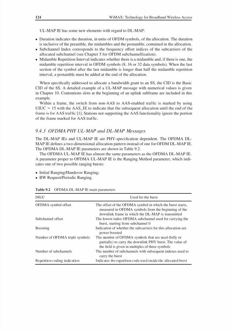
8/10/2019 WiMax-Tech for BBW Access
http://slidepdf.com/reader/full/wimax-tech-for-bbw-access 141/293
124 WiMAX: Technology for Broadband Wireless Access
UL-MAP IE has some new elements with regard to DL-MAP:
• Duration indicates the duration, in units of OFDM symbols, of the allocation. The duration
is inclusive of the preamble, the midambles and the postamble, contained in the allocation.
• Subchannel Index corresponds to the frequency offset indices of the subcarriers of theallocated subchannel (see Chapter 5 for OFDM subchannellisation).
• Midamble Repetition Interval indicates whether there is a midamble and, if there is one, the
midamble repetition interval in OFDM symbols (8, 16 or 32 data symbols). When the last
section of the symbol after the last midamble is longer than half the midamble repetition
interval, a postamble must be added at the end of the allocation.
When specifically addressed to allocate a bandwidth grant to an SS, the CID is the Basic
CID of the SS. A detailed example of a UL-MAP message with numerical values is given
in Chapter 10. Contentions slots at the beginning of an uplink subframe are included in this
example.Within a frame, the switch from non-AAS to AAS-enabled traf fic is marked by using
UIUC 15 with the AAS_IE to indicate that the subsequent allocation until the end of the
frame is for AAS traf fic [1]. Stations not supporting the AAS functionality ignore the portion
of the frame marked for AAS traf fic.
9.4.3 OFDMA PHY UL-MAP and DL-MAP Messages
The DL-MAP IEs and UL-MAP IE are PHY-specification dependent. The OFDMA DL-
MAP IE defines a two-dimensional allocation pattern instead of one for OFDM DL-MAP IE.
The OFDMA DL-MAP IE parameters are shown in Table 9.2.The OFDMA UL-MAP IE has almost the same parameters as the OFDMA DL-MAP IE.
A parameter proper to OFDMA UL-MAP IE is the Ranging Method parameter, which indi-
cates one of two possible ranging bursts:
• Initial Ranging/Handover Ranging;
• BW Request/Periodic Ranging.
Table 9.2 OFDMA DL-MAP IE main parameters
DIUC Used for the burst
OFDMA symbol offset The offset of the OFDMA symbol in which the burst starts,
measured in OFDMA symbols from the beginning of the
downlink frame in which the DL-MAP is transmitted
Subchannel offset The lowest index OFDMA subchannel used for carrying the
burst, starting from subchannel 0
Boosting Indication of whether the subcarriers for this allocation are
power boosted
Number of OFDMA triple symbols The number of OFDMA symbols that are used (fully or
partially) to carry the downlink PHY burst. The value of
the field is given in multiples of three symbols
Number of subchannels The number of subchannels with subsequent indexes used tocarry the burst
Repetition coding indication Indicates the repetition code used inside the allocated burst
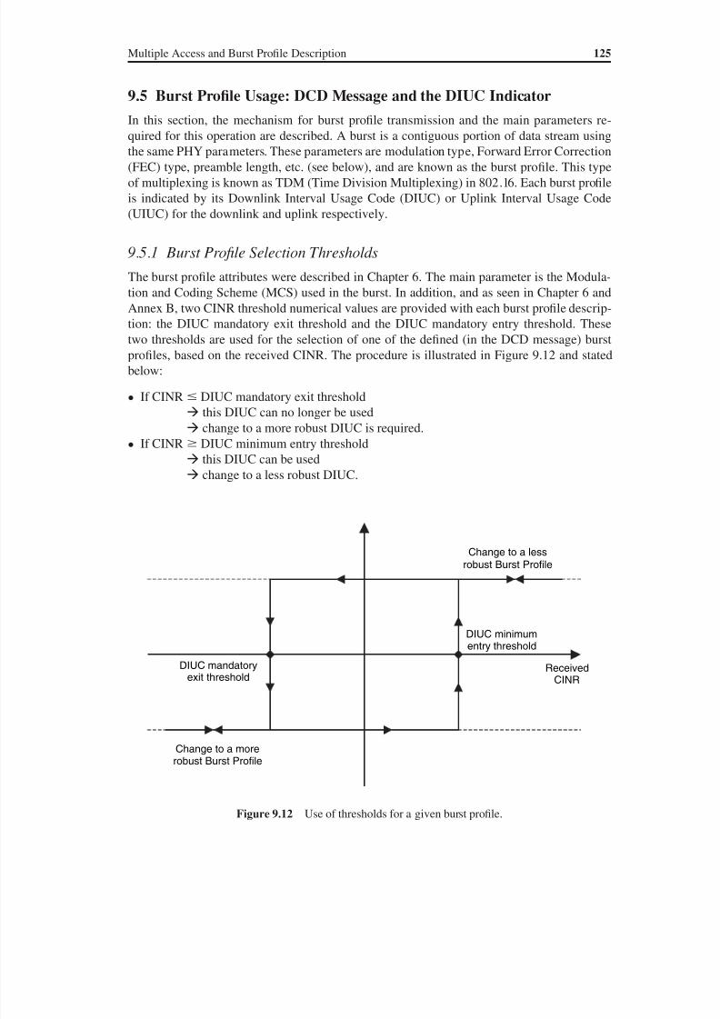
8/10/2019 WiMax-Tech for BBW Access
http://slidepdf.com/reader/full/wimax-tech-for-bbw-access 142/293
Multiple Access and Burst Profile Description 125
9.5 Burst Profile Usage: DCD Message and the DIUC Indicator
In this section, the mechanism for burst profile transmission and the main parameters re-
quired for this operation are described. A burst is a contiguous portion of data stream using
the same PHY parameters. These parameters are modulation type, Forward Error Correction(FEC) type, preamble length, etc. (see below), and are known as the burst profile. This type
of multiplexing is known as TDM (Time Division Multiplexing) in 802.16. Each burst profile
is indicated by its Downlink Interval Usage Code (DIUC) or Uplink Interval Usage Code
(UIUC) for the downlink and uplink respectively.
9.5.1 Burst Profile Selection Thresholds
The burst profile attributes were described in Chapter 6. The main parameter is the Modula-
tion and Coding Scheme (MCS) used in the burst. In addition, and as seen in Chapter 6 and
Annex B, two CINR threshold numerical values are provided with each burst profile descrip-tion: the DIUC mandatory exit threshold and the DIUC mandatory entry threshold. These
two thresholds are used for the selection of one of the defined (in the DCD message) burst
profiles, based on the received CINR. The procedure is illustrated in Figure 9.12 and stated
below:
• If CINR DIUC mandatory exit threshold
this DIUC can no longer be used
change to a more robust DIUC is required.
• If CINR DIUC minimum entry threshold
this DIUC can be used change to a less robust DIUC.
Figure 9.12 Use of thresholds for a given burst profile.
DIUC minimumentry threshold
DIUC mandatoryexit threshold
ReceivedCINR
Change to a lessrobust Burst Profile
Change to a morerobust Burst Profile
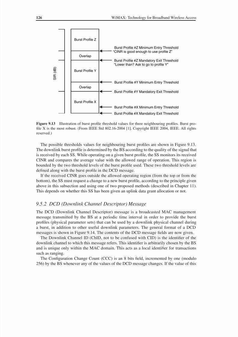
8/10/2019 WiMax-Tech for BBW Access
http://slidepdf.com/reader/full/wimax-tech-for-bbw-access 143/293
126 WiMAX: Technology for Broadband Wireless Access
The possible thresholds values for neighbouring burst profiles are shown in Figure 9.13.
The downlink burst profile is determined by the BS according to the quality of the signal that
is received by each SS. While operating on a given burst profile, the SS monitors its receivedCINR and compares the average value with the allowed range of operation. This region is
bounded by the two threshold levels of the burst profile used. These two threshold levels are
defined along with the burst profile in the DCD message.
If the received CINR goes outside the allowed operating region (from the top or from the
bottom), the SS must request a change to a new burst profile, according to the principle given
above in this subsection and using one of two proposed methods (described in Chapter 11).
This depends on whether this SS has been given an uplink data grant allocation or not.
9.5.2 DCD (Downlink Channel Descriptor) MessageThe DCD (Downlink Channel Descriptor) message is a broadcasted MAC management
message transmitted by the BS at a periodic time interval in order to provide the burst
profiles (physical parameter sets) that can be used by a downlink physical channel during
a burst, in addition to other useful downlink parameters. The general format of a DCD
messages is shown in Figure 9.14. The contents of the DCD message fields are now given.
The Downlink Channel ID (ChID, not to be confused with CID) is the identifier of the
downlink channel to which this message refers. This identifier is arbitrarily chosen by the BS
and is unique only within the MAC domain. This acts as a local identifier for transactions
such as ranging.
The Configuration Change Count (CCC) is an 8 bits field, incremented by one (modulo
256) by the BS whenever any of the values of the DCD message changes. If the value of this
Figure 9.13 Illustration of burst profile threshold values for three neighbouring profiles. Burst pro-
file X is the most robust. (From IEEE Std 802.16-2004 [1]. Copyright IEEE 2004, IEEE. All rights
reserved.)
Burst Profile Y
Burst Profile Z
Burst Profile X
Overlap
Overlap
S I R
( d B )
Burst Profile #Z Minimum Entry Threshold
“CINR is good enough to use profile Z”
Burst Profile #Y Minimum Entry Threshold
Burst Profile #Z Mandatory Exit Threshold“Lower than? Ask to go to profile Y”
Burst Profile #Y Mandatory Exit Threshold
Burst Profile #X Mandatory Exit Threshold
Burst Profile #X Minimum Entry Threshold
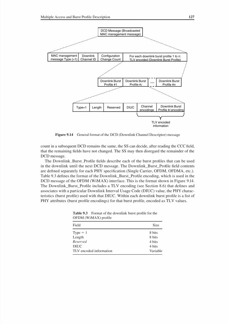
8/10/2019 WiMax-Tech for BBW Access
http://slidepdf.com/reader/full/wimax-tech-for-bbw-access 144/293
Multiple Access and Burst Profile Description 127
count in a subsequent DCD remains the same, the SS can decide, after reading the CCC field,that the remaining fields have not changed. The SS may then disregard the remainder of the
DCD message.
The Downlink_Burst_Profile fields describe each of the burst profiles that can be used
in the downlink until the next DCD message. The Downlink_Burst_Profile field contents
are defined separately for each PHY specification (Single Carrier, OFDM, OFDMA, etc.).
Table 9.3 defines the format of the Downlink_Burst_Profile encoding, which is used in the
DCD message of the OFDM (WiMAX) interface. This is the format shown in Figure 9.14.
The Downlink_Burst_Profile includes a TLV encoding (see Section 8.6) that defines and
associates with a particular Downlink Interval Usage Code (DIUC) value, the PHY charac-
teristics (burst profile) used with that DIUC. Within each downlink burst profile is a list ofPHY attributes (burst profile encodings) for that burst profile, encoded as TLV values.
Figure 9.14 General format of the DCD (Downlink Channel Descriptor) message
DCD Message (BroadcastedMAC management message)
DownlinkChannel ID
ConfigurationChange Count
For each downlink burst profile 1 to n:TLV encoded (Downlink Burst Profile)
Downlink BurstProfile #n
…
Downlink BurstProfile #i
Downlink BurstProfile #1
Type=1 Length DIUCReserved Channelencodings
Downlink BurstProfile #i encoding
TLV encodedinformation
MAC managementmessage Type (=1)
Table 9.3 Format of the downlink burst profile for the
OFDM (WiMAX) profile
Field Size
Type 1 8 bits
Length 8 bits
Reserved 4 bits
DIUC 4 bitsTLV encoded information Variable
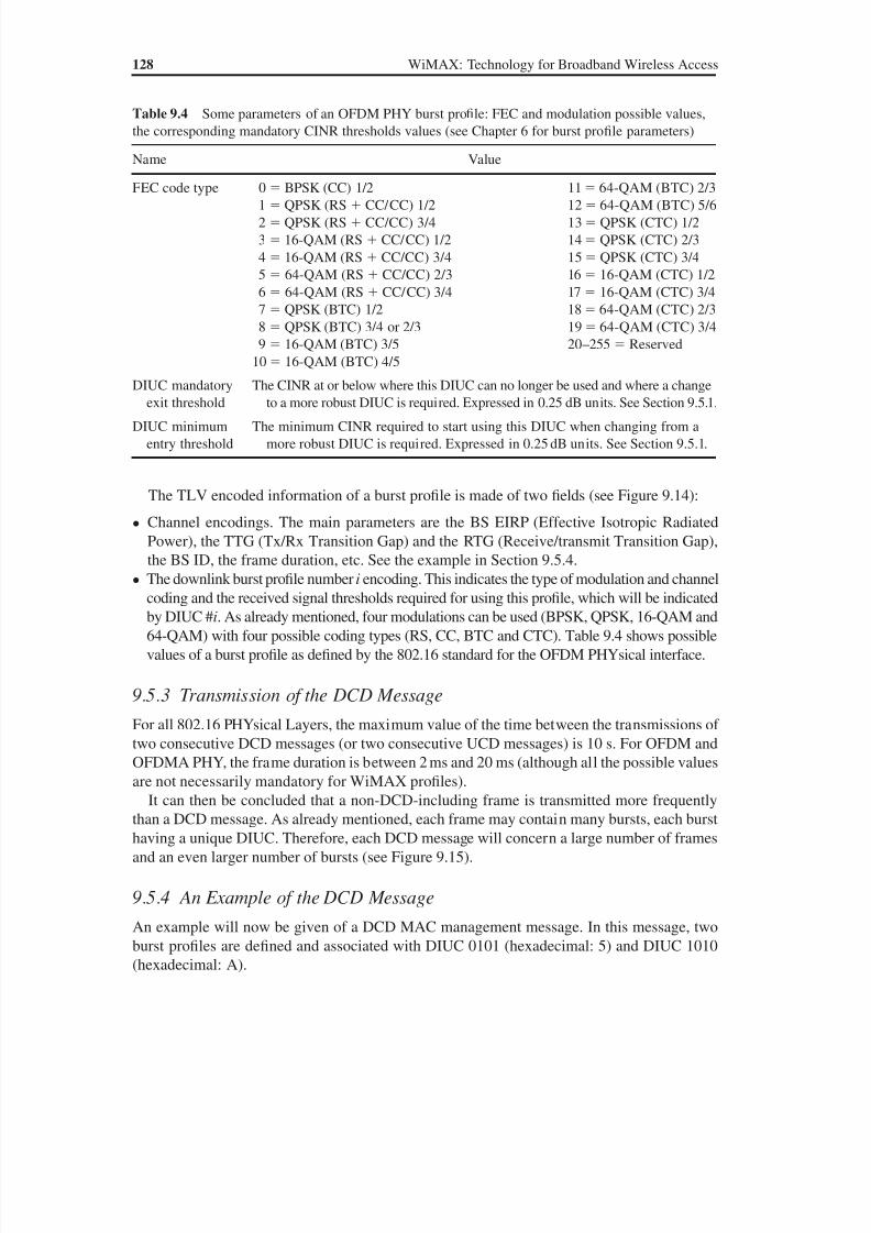
8/10/2019 WiMax-Tech for BBW Access
http://slidepdf.com/reader/full/wimax-tech-for-bbw-access 145/293
128 WiMAX: Technology for Broadband Wireless Access
The TLV encoded information of a burst profile is made of two fields (see Figure 9.14):
• Channel encodings. The main parameters are the BS EIRP (Effective Isotropic Radiated
Power), the TTG (Tx/Rx Transition Gap) and the RTG (Receive/transmit Transition Gap),
the BS ID, the frame duration, etc. See the example in Section 9.5.4.• The downlink burst profile number i encoding. This indicates the type of modulation and channel
coding and the received signal thresholds required for using this profile, which will be indicated
by DIUC #i. As already mentioned, four modulations can be used (BPSK, QPSK, 16-QAM and
64-QAM) with four possible coding types (RS, CC, BTC and CTC). Table 9.4 shows possible
values of a burst profile as defined by the 802.16 standard for the OFDM PHYsical interface.
9.5.3 Transmission of the DCD Message
For all 802.16 PHYsical Layers, the maximum value of the time between the transmissions of
two consecutive DCD messages (or two consecutive UCD messages) is 10 s. For OFDM andOFDMA PHY, the frame duration is between 2 ms and 20 ms (although all the possible values
are not necessarily mandatory for WiMAX profiles).
It can then be concluded that a non-DCD-including frame is transmitted more frequently
than a DCD message. As already mentioned, each frame may contain many bursts, each burst
having a unique DIUC. Therefore, each DCD message will concern a large number of frames
and an even larger number of bursts (see Figure 9.15).
9.5.4 An Example of the DCD Message
An example will now be given of a DCD MAC management message. In this message, two
burst profiles are defined and associated with DIUC 0101 (hexadecimal: 5) and DIUC 1010
(hexadecimal: A).
Table 9.4 Some parameters of an OFDM PHY burst profile: FEC and modulation possible values,
the corresponding mandatory CINR thresholds values (see Chapter 6 for burst profile parameters)
Name Value
FEC code type 0 BPSK (CC) 1/2 11 64-QAM (BTC) 2/31 QPSK (RS CC/CC) 1/2 12 64-QAM (BTC) 5/6
2 QPSK (RS CC/CC) 3/4 13 QPSK (CTC) 1/2
3 16-QAM (RS CC/CC) 1/2 14 QPSK (CTC) 2/3
4 16-QAM (RS CC/CC) 3/4 15 QPSK (CTC) 3/4
5 64-QAM (RS CC/CC) 2/3 16 16-QAM (CTC) 1/2
6 64-QAM (RS CC/CC) 3/4 17 16-QAM (CTC) 3/4
7 QPSK (BTC) 1/2 18 64-QAM (CTC) 2/3
8 QPSK (BTC) 3/4 or 2/3 19 64-QAM (CTC) 3/4
9 16-QAM (BTC) 3/5 20–255 Reserved
10 16-QAM (BTC) 4/5
DIUC mandatory
exit threshold
The CINR at or below where this DIUC can no longer be used and where a change
to a more robust DIUC is required. Expressed in 0.25 dB units. See Section 9.5.1.
DIUC minimum
entry threshold
The minimum CINR required to start using this DIUC when changing from a
more robust DIUC is required. Expressed in 0.25 dB units. See Section 9.5.1.
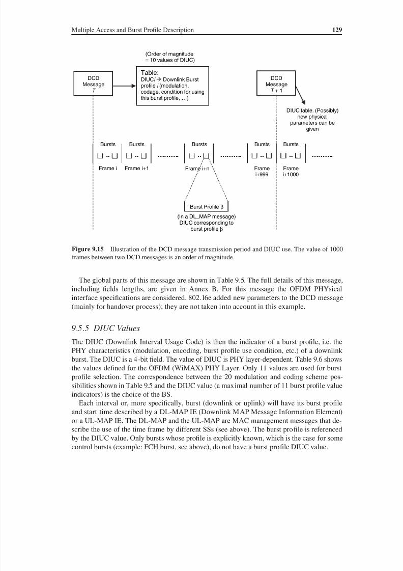
8/10/2019 WiMax-Tech for BBW Access
http://slidepdf.com/reader/full/wimax-tech-for-bbw-access 146/293
Multiple Access and Burst Profile Description 129
The global parts of this message are shown in Table 9.5. The full details of this message,
including fields lengths, are given in Annex B. For this message the OFDM PHYsical
interface specifications are considered. 802.16e added new parameters to the DCD message
(mainly for handover process); they are not taken into account in this example.
9.5.5 DIUC Values
The DIUC (Downlink Interval Usage Code) is then the indicator of a burst profile, i.e. the
PHY characteristics (modulation, encoding, burst profile use condition, etc.) of a downlink
burst. The DIUC is a 4-bit field. The value of DIUC is PHY layer-dependent. Table 9.6 shows
the values defined for the OFDM (WiMAX) PHY Layer. Only 11 values are used for burst
profile selection. The correspondence between the 20 modulation and coding scheme pos-
sibilities shown in Table 9.5 and the DIUC value (a maximal number of 11 burst profile value
indicators) is the choice of the BS.
Each interval or, more specifically, burst (downlink or uplink) will have its burst profile
and start time described by a DL-MAP IE (Downlink MAP Message Information Element)
or a UL-MAP IE. The DL-MAP and the UL-MAP are MAC management messages that de-
scribe the use of the time frame by different SSs (see above). The burst profile is referenced
by the DIUC value. Only bursts whose profile is explicitly known, which is the case for some
control bursts (example: FCH burst, see above), do not have a burst profile DIUC value.
Figure 9.15 Illustration of the DCD message transmission period and DIUC use. The value of 1000
frames between two DCD messages is an order of magnitude.
DIUC table. (Possibly)new physical
parameters can begiven
DCD
MessageT
Table:DIUCi Downlink Burst
profile i (modulation,codage, condition for usingthis burst profile, …)
(Order of magnitude= 10 values of DIUC)
.. ..
Frame i Frame i+1
Bursts
………. ..
Frame i+n
Bursts Bursts
Burst Profile β
(In a DL_MAP message)DIUC corresponding to
burst profile β
………. ..
Frame
i+999
Bursts
..
Frame
i+1000
Bursts
DCD
MessageT + 1
……….
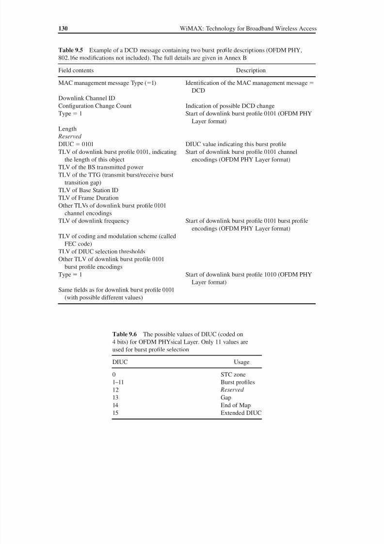
8/10/2019 WiMax-Tech for BBW Access
http://slidepdf.com/reader/full/wimax-tech-for-bbw-access 147/293
130 WiMAX: Technology for Broadband Wireless Access
Table 9.5 Example of a DCD message containing two burst profile descriptions (OFDM PHY,
802.16e modifications not included). The full details are given in Annex B
Field contents Description
MAC management message Type (1) Identification of the MAC management message DCD
Downlink Channel ID
Configuration Change Count Indication of possible DCD change
Type 1 Start of downlink burst profile 0101 (OFDM PHY
Layer format)
Length
Reserved
DIUC 0101 DIUC value indicating this burst profile
TLV of downlink burst profile 0101, indicating
the length of this object
Start of downlink burst profile 0101 channel
encodings (OFDM PHY Layer format)
TLV of the BS transmitted power
TLV of the TTG (transmit burst/receive burst
transition gap)
TLV of Base Station ID
TLV of Frame Duration
Other TLVs of downlink burst profile 0101
channel encodings
TLV of downlink frequency Start of downlink burst profile 0101 burst profile
encodings (OFDM PHY Layer format)
TLV of coding and modulation scheme (called
FEC code)
TLV of DIUC selection thresholds
Other TLV of downlink burst profile 0101
burst profile encodings
Type 1 Start of downlink burst profile 1010 (OFDM PHY
Layer format)
Same fields as for downlink burst profile 0101
(with possible different values)
Table 9.6 The possible values of DIUC (coded on
4 bits) for OFDM PHYsical Layer. Only 11 values are
used for burst profile selection
DIUC Usage
0 STC zone
1–11 Burst profiles
12 Reserved
13 Gap
14 End of Map
15 Extended DIUC
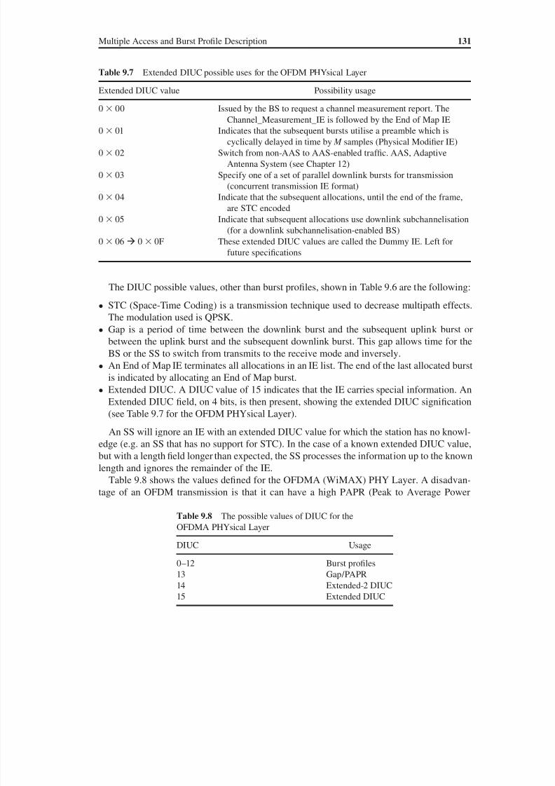
8/10/2019 WiMax-Tech for BBW Access
http://slidepdf.com/reader/full/wimax-tech-for-bbw-access 148/293
Multiple Access and Burst Profile Description 131
The DIUC possible values, other than burst profiles, shown in Table 9.6 are the following:
• STC (Space-Time Coding) is a transmission technique used to decrease multipath effects.
The modulation used is QPSK.
• Gap is a period of time between the downlink burst and the subsequent uplink burst or
between the uplink burst and the subsequent downlink burst. This gap allows time for the
BS or the SS to switch from transmits to the receive mode and inversely.• An End of Map IE terminates all allocations in an IE list. The end of the last allocated burst
is indicated by allocating an End of Map burst.
• Extended DIUC. A DIUC value of 15 indicates that the IE carries special information. An
Extended DIUC field, on 4 bits, is then present, showing the extended DIUC signification
(see Table 9.7 for the OFDM PHYsical Layer).
An SS will ignore an IE with an extended DIUC value for which the station has no knowl-
edge (e.g. an SS that has no support for STC). In the case of a known extended DIUC value,
but with a length field longer than expected, the SS processes the information up to the known
length and ignores the remainder of the IE.
Table 9.8 shows the values defined for the OFDMA (WiMAX) PHY Layer. A disadvan-tage of an OFDM transmission is that it can have a high PAPR (Peak to Average Power
Table 9.7 Extended DIUC possible uses for the OFDM PHYsical Layer
Extended DIUC value Possibility usage
0 00 Issued by the BS to request a channel measurement report. The
Channel_Measurement_IE is followed by the End of Map IE0 01 Indicates that the subsequent bursts utilise a preamble which is
cyclically delayed in time by M samples (Physical Modifier IE)
0 02 Switch from non-AAS to AAS-enabled traf fic. AAS, Adaptive
Antenna System (see Chapter 12)
0 03 Specify one of a set of parallel downlink bursts for transmission
(concurrent transmission IE format)
0 04 Indicate that the subsequent allocations, until the end of the frame,
are STC encoded
0 05 Indicate that subsequent allocations use downlink subchannelisation
(for a downlink subchannelisation-enabled BS)
0 06 0 0F These extended DIUC values are called the Dummy IE. Left for
future specifications
Table 9.8 The possible values of DIUC for the
OFDMA PHYsical Layer
DIUC Usage
0–12 Burst profiles
13 Gap/PAPR
14 Extended-2 DIUC
15 Extended DIUC

8/10/2019 WiMax-Tech for BBW Access
http://slidepdf.com/reader/full/wimax-tech-for-bbw-access 149/293
132 WiMAX: Technology for Broadband Wireless Access
Ratio). The PAPR is the peak value of transmitted subcarriers to the average transmitted
signal. A high PAPR represents a hard constraint for some devices (such as amplifiers).
DIUC 13 may be used for the allocation of subchannels for PAPR reduction schemes.
The subcarriers within these subchannels may be used by all SSs to reduce the PAPR of
their transmissions. The SS will ignore the received signal (subcarriers) in the GAP/PAPRreduction region.
9.5.6 UCD (Uplink Channel Descriptor) Message and UIUC Indicator
The UCD (Uplink Channel Descriptor) message is a broadcasted MAC management message
transmitted by the BS at a periodic time interval in order to provide the burst profile (physical
parameter sets) description that can be used by an uplink physical channel in addition to other
useful uplink parameters. Its functioning is very similar to the DCD so will not be described
in as much detail.
A UCD message must be transmitted by the BS at a periodic interval in order to de fine the
characteristics of an uplink physical channel. The maximum allowed value for this period is
10 s (as for DCD). The UCD message of OFDM PHY includes the following parameters:
• Configuration Change Count. This is the same as for DCD.
• Ranging Backoff Start and Ranging Backoff End (8 bits each). These are initial backoff and
final (or maximum) backoff window sizes for initial ranging contention (see Chapter 11),
expressed as a power of 2. Values of these exponents are in the range 0–15.
• Request Backoff Start and Request Backoff End (8 bits each). These are initial backoff and
final (or maximum) backoff window sizes for contention BW (bandwidth) requests (see
Chapter 10), expressed as a power of 2. Values of these exponents are in the range 0–15.
• For each uplink burst profile defined in this UCD message, Uplink_Burst_Profile, which
is a compound TLV encoding that defines and associates with a particular UIUC, the PHY
characteristics that must be used with that UIUC. The TLV encoded values of a burst profile
are globally similar to the ones of the downlink burst profiles in the DCD message. The
following ones are burst profile parameters specific to UCD:
• Contention-based reservation timeout. This is the number of UL-MAPs received before a
contention-based reservation is attempted again for the same connection.
• Bandwidth request opportunity size. This is the size (in units of PS) of the PHY payload
that an SS may use to format and transmit a bandwidth request message in a contention re-
quest opportunity. The value includes all PHY overhead as well as allowance for the MAC
data the message may hold.
• Ranging request opportunity size. This is the size (in units of PS) of the PHY bursts that
an SS may use to transmit a Ranging Request message in a contention ranging request op-
portunity (see Chapter 11). The value includes all PHY overheads and (in addition to the
bandwidth request opportunity size content) the maximum SS/BS round trip propagation
delay.
• Subchannelisation REQ Region-Full Parameters. This is the number of subchannels used
by each transmit opportunity when REQ Region-Full is allocated in a subchannelisation
region. Possible values are between 1 and 16 subchannels (see Section 10.4).
• Subchannelisation focused contention codes. This is the number of contention codes
(CSE) that can be used to request a subchannelised allocation. The default value is 0 (no
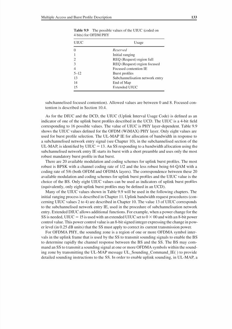
8/10/2019 WiMax-Tech for BBW Access
http://slidepdf.com/reader/full/wimax-tech-for-bbw-access 150/293
Multiple Access and Burst Profile Description 133
subchannelised focused contention). Allowed values are between 0 and 8. Focused con-
tention is described in Section 10.4.
As for the DIUC and the DCD, the UIUC (Uplink Interval Usage Code) is defined as an
indicator of one of the uplink burst profiles described in the UCD. The UIUC is a 4-bit field
corresponding to 16 possible values. The value of UIUC is PHY layer-dependent. Table 9.9
shows the UIUC values defined for the OFDM (WiMAX) PHY layer. Only eight values are
used for burst profile selection. The UL-MAP IE for allocation of bandwidth in response to
a subchannelised network entry signal (see Chapter 10), in the subchannelised section of the
UL-MAP, is identified by UIUC 13. An SS responding to a bandwidth allocation using the
subchannelised network entry IE starts its burst with a short preamble and uses only the most
robust mandatory burst profile in that burst.
There are 20 available modulation and coding schemes for uplink burst profiles. The most
robust is BPSK with a channel coding rate of 1/2 and the less robust being 64-QAM with a
coding rate of 5/6 (both OFDM and OFDMA layers). The correspondence between these 20
available modulation and coding schemes for uplink burst profiles and the UIUC value is the
choice of the BS. Only eight UIUC values can be used as indicators of uplink burst profiles
(equivalently, only eight uplink burst profiles may be defined in an UCD).
Many of the UIUC values shown in Table 9.9 will be used in the following chapters. The
initial ranging process is described in Chapter 11. Uplink bandwidth request procedures (con-
cerning UIUC values 2 to 4) are described in Chapter 10. The value 13 of UIUC corresponds
to the subchannelised network entry IE, used in the procedure of subchannelisation network
entry. Extended DIUC allows additional functions. For example, when a power change for the
SS is needed, UIUC 15 is used with an extended UIUC set to 0 00 and with an 8-bit power
control value. This power control value is an 8-bit signed integer expressing the change in pow-
er level (in 0.25 dB units) that the SS must apply to correct its current transmission power.
For OFDMA PHY, the sounding zone is a region of one or more OFDMA symbol inter-
vals in the uplink frame that is used by the SS to transmit sounding signals to enable the BS
to determine rapidly the channel response between the BS and the SS. The BS may com-
mand an SS to transmit a sounding signal at one or more OFDMA symbols within the sound-
ing zone by transmitting the UL-MAP message UL_Sounding_Command_IE( ) to provide
detailed sounding instructions to the SS. In order to enable uplink sounding, in UL-MAP, a
Table 9.9 The possible values of the UIUC (coded on
4 bits) for OFDM PHY
UIUC Usage
0 Reserved 1 Initial ranging
2 REQ (Request) region full
3 REQ (Request) region focused
4 Focused contention IE
5–12 Burst profiles
13 Subchannelisation network entry
14 End of Map
15 Extended UIUC
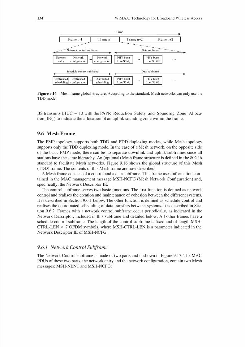
8/10/2019 WiMax-Tech for BBW Access
http://slidepdf.com/reader/full/wimax-tech-for-bbw-access 151/293

8/10/2019 WiMax-Tech for BBW Access
http://slidepdf.com/reader/full/wimax-tech-for-bbw-access 152/293
Multiple Access and Burst Profile Description 135
• MSH-NENT (Mesh Network Entry) is a basic MAC management message that provides
the means for a new node to gain synchronisation and initial network entry into a Mesh
network.
• MSH-NCFG (Mesh Network Configuration) is a broadcasted MAC management message
that provides a basic level of communication between nodes in different nearby networks,
whether from the same or different equipment vendors or wireless operators. Among others,
the Network Descriptor is an embedded data of the MSH-NCFG message. The NetworkDescriptor contains many channel parameters (modulation and coding schemes, threshold
values, etc.), which makes it similar to the UCD and DCD.
9.6.2 Schedule Control Subframe
The Schedule Control subframe is made of three parts and is shown in Figure 9.18. The MAC
PDUs of these three parts, the centralised configuration, the centralised scheduling and the
distributed scheduling contain three Mesh messages: MSH-CSCF, MSH-CSCH and MSH-
DSCH:
• MSH-CSCF (Mesh Centralised Schedule Configuration) and MSH-CSCH (Mesh Cen-
tralised Schedule) are broadcasted MAC management messages that are broadcasted in the
Mesh mode when using centralised scheduling. The Mesh BS broadcasts these messages to
all its neighbours and all nodes forward (rebroadcast) them.
The Mesh BS may create a MSH-CSCH message and broadcast it to all its neighbours
to grant bandwidth to a given node, and then all the nodes with a hop count lower than a
given threshold forward the MSH-CSCH message to their neighbours that have a higher
hop count. On the other hand, nodes can use MSH-CSCH messages to request bandwidths
from the Mesh BS. Each node reports the individual traf fic demand requests of each ‘child’
node in its subtree to the Mesh BS.
Figure 9.17 The two parts of the Network Control subframe of the Mesh subframe. The network con-figuration contains the Network Descriptor
Network
entry
Longpreamble
MAC PDU(MSH_NENT)
Guardsymbol
Guardsymbol
Guardsymbol
Network
configuration
Long
preamble
MAC PDU
(MSH_NCFG)
Guard
symbol
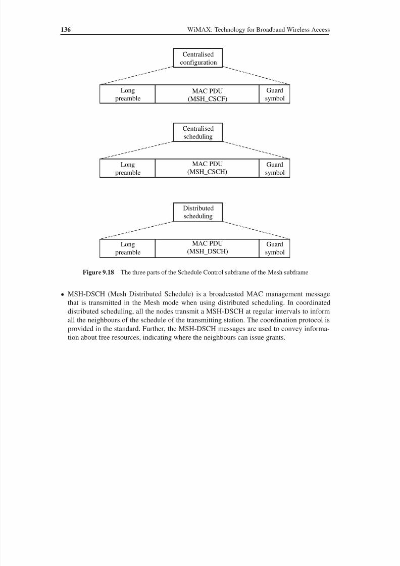
8/10/2019 WiMax-Tech for BBW Access
http://slidepdf.com/reader/full/wimax-tech-for-bbw-access 153/293
8/10/2019 WiMax-Tech for BBW Access
http://slidepdf.com/reader/full/wimax-tech-for-bbw-access 154/293
10Uplink Bandwidth Allocationand Request Mechanisms
10.1 Downlink and Uplink Allocation of Bandwidth
Downlink and uplink bandwidth allocations are completely different. The 802.16 standard
has a MAC centralised architecture where the BS scheduler controls all the system param-
eters, including the radio interface. It is the role of this BS scheduler to determine the uplink
and downlink accesses. The uplink and downlink subframe details were given in Chapter 9.
The downlink allocation of bandwidth is a process accomplished by the BS according to
different parameters that are determinant in the bandwidth allocation. Taking into consider-
ation the QoS class for the connection and the quantity of traffic required, the BS scheduler
supervises the link and determines which SS will have downlink burst(s) and the appropriate
burst profile. In this chapter, the uplink access mechanisms of WiMAX/802.16 are described.
Chapter 11 describes scheduling and QoS.
In the uplink of each BS zone or, equivalently, WiMAX cell, the SSs must follow a trans-
mission protocol that controls contention between them and enables the transmission services
to be tailored to the delay and bandwidth requirements of each user application. This is ac-
complished while taking into account five classes of uplink service levels, corresponding to
the five QoS classes that uplink transmissions may have.
Uplink access and bandwidth allocation are realised using one of the four following
methods:
• unsolicited bandwidth grants;
• piggyback bandwidth request;
• unicast polling, sometimes simply referred to as polling;
• contention-based procedures, including broadcast or multicast polling, where contention-
based bandwidth request procedures have variants depending of the PHYsical Layer used:
OFDM or OFDMA (see below).
The standard states that these mechanisms are defined to allow vendors to optimise system
performance by using different combinations of these bandwidth allocation techniques while
WiMAX: Technology for Broadband Wireless Access Loutfi Nuaymi
© 2007 John Wiley & Sons, Ltd. ISBN: 0-470-02808-4
8/10/2019 WiMax-Tech for BBW Access
http://slidepdf.com/reader/full/wimax-tech-for-bbw-access 155/293
138 WiMAX: Technology for Broadband Wireless Access
maintaining consistent interoperability. The standard proposes, as an example, the use of
contention instead of individual polling for SSs that have been inactive for a long period of
time. Next, the realisation of these methods is described, but first two possible differentiations
of an uplink grant-request are introduced.
10.2 Types of Uplink Access Grant-request
The BS decides transmissions in the uplink and the downlink. For uplink access, a grant is
defined as the right for an SS to transmit during a certain duration. Requests for bandwidth
must be made in terms of the number of bytes needed to carry the MAC header and payload,
but not the PHY overhead. For an SS, bandwidth requests reference individual connections
while each bandwidth grant is addressed to the SS’s Basic CID, not to individual CIDs. It is
then up to the SS to use the attributed bandwidth for any of its CIDs. Since it is nondeter-
ministic which request is being honoured, when the SS receives a shorter transmission op-
portunity than expected due to a scheduler decision, the request message loss or some other
possible reason, no explicit reason is given.
Grants are then given by the BS after receipt of a request from an SS. Two possible differ-
entiations can be made for this request. These differentiations are now described.
10.2.1 Incremental and Aggregate Bandwidth Request
A grant-request (by an SS) may be incremental or aggregate:
• When the BS receives an incremental bandwidth request, it adds the quantity of bandwidth
requested to its current perception of the bandwidth needs of the connection.
• When the BS receives an aggregate bandwidth request, it replaces its perception of the
bandwidth needs of the connection with the quantity of bandwidth requested.
The self-correcting nature of the request-grant protocol requires that the SSs should pe-
riodically use aggregate Bandwidth Requests. The standard states that this period may be a
function of the QoS of a service and of the link quality, but do not give a precise value for it.
The grant-request may be sent in two possible MAC frame types that are described in the
following subsection. Only the first one (the standalone bandwidth request) can be aggregate or
incremental.
10.2.2 Standalone and Piggyback Bandwidth Request
The two MAC frame types of the 802.16 standard, already defined in Section 8.2, can be
used by an SS to request bandwidth allocation from the BS. Specifically, Section 8.2.3 details
MAC headers and gives two types of request that are now described.
The standalone bandwidth request is transmitted in a dedicated MAC frame having a
Header format without payload Type I, indicated by the first bit of the frame, the Header
Type bit, being equal to 1. A Type field in the bandwidth request header indicates whether
the request is incremental or aggregate (see Table 8.3). In the bandwidth request header, a
19-bit long bandwidth request field, the Bandwidth Request field, indicates the number of
bytes of the uplink bandwidth requested by the SS for a given CID, also given in this header.
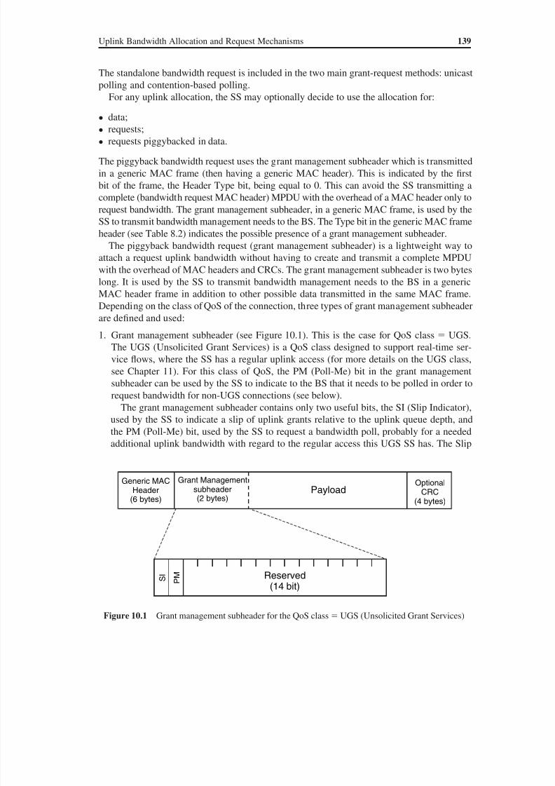
8/10/2019 WiMax-Tech for BBW Access
http://slidepdf.com/reader/full/wimax-tech-for-bbw-access 156/293
Uplink Bandwidth Allocation and Request Mechanisms 139
The standalone bandwidth request is included in the two main grant-request methods: unicast
polling and contention-based polling.
For any uplink allocation, the SS may optionally decide to use the allocation for:
• data;• requests;
• requests piggybacked in data.
The piggyback bandwidth request uses the grant management subheader which is transmitted
in a generic MAC frame (then having a generic MAC header). This is indicated by the first
bit of the frame, the Header Type bit, being equal to 0. This can avoid the SS transmitting a
complete (bandwidth request MAC header) MPDU with the overhead of a MAC header only to
request bandwidth. The grant management subheader, in a generic MAC frame, is used by the
SS to transmit bandwidth management needs to the BS. The Type bit in the generic MAC frame
header (see Table 8.2) indicates the possible presence of a grant management subheader.The piggyback bandwidth request (grant management subheader) is a lightweight way to
attach a request uplink bandwidth without having to create and transmit a complete MPDU
with the overhead of MAC headers and CRCs. The grant management subheader is two bytes
long. It is used by the SS to transmit bandwidth management needs to the BS in a generic
MAC header frame in addition to other possible data transmitted in the same MAC frame.
Depending on the class of QoS of the connection, three types of grant management subheader
are defined and used:
1. Grant management subheader (see Figure 10.1). This is the case for QoS class UGS.
The UGS (Unsolicited Grant Services) is a QoS class designed to support real-time ser-
vice flows, where the SS has a regular uplink access (for more details on the UGS class,see Chapter 11). For this class of QoS, the PM (Poll-Me) bit in the grant management
subheader can be used by the SS to indicate to the BS that it needs to be polled in order to
request bandwidth for non-UGS connections (see below).
The grant management subheader contains only two useful bits, the SI (Slip Indicator),
used by the SS to indicate a slip of uplink grants relative to the uplink queue depth, and
the PM (Poll-Me) bit, used by the SS to request a bandwidth poll, probably for a needed
additional uplink bandwidth with regard to the regular access this UGS SS has. The Slip
Grant Managementsubheader(2 bytes)
OptionalCRC
(4 bytes)
Payload
I S
M P
Reserved(14 bit)
Generic MACHeader
(6 bytes)
Figure 10.1 Grant management subheader for the QoS class UGS (Unsolicited Grant Services)
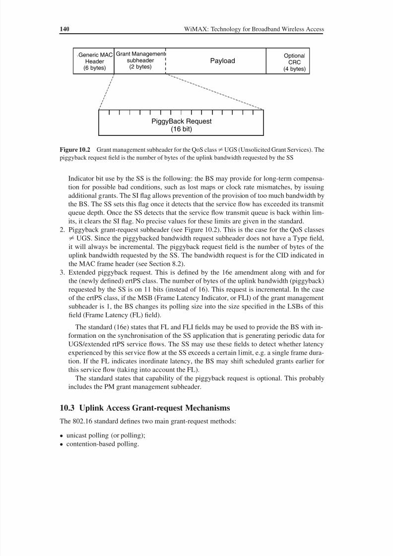
8/10/2019 WiMax-Tech for BBW Access
http://slidepdf.com/reader/full/wimax-tech-for-bbw-access 157/293
140 WiMAX: Technology for Broadband Wireless Access
Indicator bit use by the SS is the following: the BS may provide for long-term compensa-
tion for possible bad conditions, such as lost maps or clock rate mismatches, by issuing
additional grants. The SI flag allows prevention of the provision of too much bandwidth by
the BS. The SS sets this flag once it detects that the service flow has exceeded its transmit
queue depth. Once the SS detects that the service flow transmit queue is back within lim-
its, it clears the SI flag. No precise values for these limits are given in the standard.
2. Piggyback grant-request subheader (see Figure 10.2). This is the case for the QoS classes
UGS. Since the piggybacked bandwidth request subheader does not have a Type field,
it will always be incremental. The piggyback request field is the number of bytes of the
uplink bandwidth requested by the SS. The bandwidth request is for the CID indicated inthe MAC frame header (see Section 8.2).
3. Extended piggyback request. This is defined by the 16e amendment along with and for
the (newly defined) ertPS class. The number of bytes of the uplink bandwidth (piggyback)
requested by the SS is on 11 bits (instead of 16). This request is incremental. In the case
of the ertPS class, if the MSB (Frame Latency Indicator, or FLI) of the grant management
subheader is 1, the BS changes its polling size into the size specified in the LSBs of this
field (Frame Latency (FL) field).
The standard (16e) states that FL and FLI fields may be used to provide the BS with in-
formation on the synchronisation of the SS application that is generating periodic data forUGS/extended rtPS service flows. The SS may use these fields to detect whether latency
experienced by this service flow at the SS exceeds a certain limit, e.g. a single frame dura-
tion. If the FL indicates inordinate latency, the BS may shift scheduled grants earlier for
this service flow (taking into account the FL).
The standard states that capability of the piggyback request is optional. This probably
includes the PM grant management subheader.
10.3 Uplink Access Grant-request Mechanisms
The 802.16 standard defines two main grant-request methods:
• unicast polling (or polling);
• contention-based polling.
Grant Managementsubheader(2 bytes)
OptionalCRC
(4 bytes)
Payload
PiggyBack Request(16 bit)
\ Generic MACHeader
(6 bytes)
Figure 10.2 Grant management subheader for the QoS class UGS (Unsolicited Grant Services). The
piggyback request field is the number of bytes of the uplink bandwidth requested by the SS

8/10/2019 WiMax-Tech for BBW Access
http://slidepdf.com/reader/full/wimax-tech-for-bbw-access 158/293
Uplink Bandwidth Allocation and Request Mechanisms 141
By extension, the UGS class of QoS has unsolicited bandwidth grants, sometimes considered
as an (implicit) grant-request mechanism although it is based on reserved slots dedicated for
the concerned UGS class SSs. These grant-request mechanisms will now be described, start-
ing with the simplest one, unsolicited bandwidth grants.
10.3.1 Unsolicited Bandwidth Grants
The unsolicited bandwidth grants technique consists of dedicated slots reserved for UGS
class SSs. This type of bandwidth requests is useful for applications requiring a fixed rate data
stream. Figure 10.3 illustrates the unsolicited bandwidth grant mechanism in the uplink and
the downlink. This type of access grant is used only by the UGS class of QoS.
10.3.2 Unicast Polling
Polling is the process by which the BS allocates bandwidth to the SSs for the purpose of mak-
ing bandwidth requests. These allocations may be to an individual SS or to a group of SSs.
The use of polling simplifies the access operation and guarantees that applications can re-
ceive service on a deterministic basis if it is required. This allocation technique is used when
bandwidth resource demand is not relevant enough to have unsolicited bandwidth grants for
all users; the BS can then directly assign the request amount to the SS(s) as needed.
When an SS is polled individually, it is a unicast polling. In the case of unicast polling, no
explicit message is transmitted to poll the SS. Rather, the SS is allocated, in the UL-MAP,
sufficient bandwidth to respond with a Bandwidth (BW) request. The standard indicates
that for any individual uplink allocation, the SS may optionally decide to use the alloca-
tion for data, requests or requests piggybacked in data transmission. Taking into account
its (possibly) different pending uplink transmission requests, the SS scheduler decides if a
bandwidth request must be made, standalone or piggybacked with data (see Section 10.2). If
the SS do not have data to transmit and then no need for bandwidth, the allocation is padded,
eventually using a padding CID (see Table 7.1). Figure 10.4 represents the unicast polling
mechanism.
The standard states that unicast polling would normally be done on a per-SS basis by allo-
cating a Data Grant IE (or Data Grant Burst Type IE) directed at its Basic CID. A Data Grant
Data traffic sent to the BSon a reserved uplink slot
Data traffic received by theSS on a reserved downlinkslot
BS
SS
Figure 10.3 Unsolicited bandwidth grants in the uplink
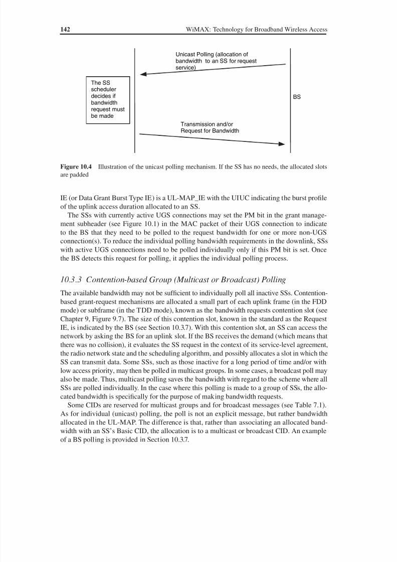
8/10/2019 WiMax-Tech for BBW Access
http://slidepdf.com/reader/full/wimax-tech-for-bbw-access 159/293
142 WiMAX: Technology for Broadband Wireless Access
IE (or Data Grant Burst Type IE) is a UL-MAP_IE with the UIUC indicating the burst profile
of the uplink access duration allocated to an SS.
The SSs with currently active UGS connections may set the PM bit in the grant manage-
ment subheader (see Figure 10.1) in the MAC packet of their UGS connection to indicate
to the BS that they need to be polled to the request bandwidth for one or more non-UGS
connection(s). To reduce the individual polling bandwidth requirements in the downlink, SSs
with active UGS connections need to be polled individually only if this PM bit is set. Once
the BS detects this request for polling, it applies the individual polling process.
10.3.3 Contention-based Group (Multicast or Broadcast) Polling
The available bandwidth may not be sufficient to individually poll all inactive SSs. Contention-
based grant-request mechanisms are allocated a small part of each uplink frame (in the FDD
mode) or subframe (in the TDD mode), known as the bandwidth requests contention slot (see
Chapter 9, Figure 9.7). The size of this contention slot, known in the standard as the Request
IE, is indicated by the BS (see Section 10.3.7). With this contention slot, an SS can access the
network by asking the BS for an uplink slot. If the BS receives the demand (which means that
there was no collision), it evaluates the SS request in the context of its service-level agreement,
the radio network state and the scheduling algorithm, and possibly allocates a slot in which the
SS can transmit data. Some SSs, such as those inactive for a long period of time and/or with
low access priority, may then be polled in multicast groups. In some cases, a broadcast poll may
also be made. Thus, multicast polling saves the bandwidth with regard to the scheme where all
SSs are polled individually. In the case where this polling is made to a group of SSs, the allo-
cated bandwidth is specifically for the purpose of making bandwidth requests.
Some CIDs are reserved for multicast groups and for broadcast messages (see Table 7.1).
As for individual (unicast) polling, the poll is not an explicit message, but rather bandwidth
allocated in the UL-MAP. The difference is that, rather than associating an allocated band-
width with an SS’s Basic CID, the allocation is to a multicast or broadcast CID. An example
of a BS polling is provided in Section 10.3.7.
BS
The SSschedulerdecides ifbandwidthrequest mustbe made
Transmission and/orRequest for Bandwidth
Unicast Polling (allocation ofbandwidth to an SS for requestservice)
Figure 10.4 Illustration of the unicast polling mechanism. If the SS has no needs, the allocated slots
are padded
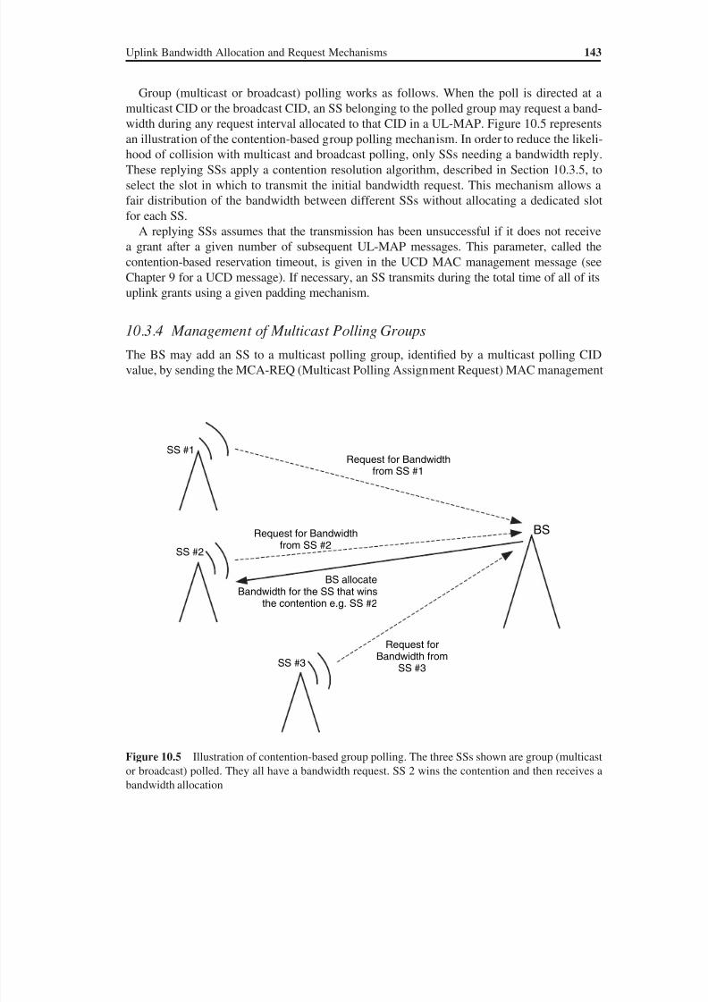
8/10/2019 WiMax-Tech for BBW Access
http://slidepdf.com/reader/full/wimax-tech-for-bbw-access 160/293
8/10/2019 WiMax-Tech for BBW Access
http://slidepdf.com/reader/full/wimax-tech-for-bbw-access 161/293
144 WiMAX: Technology for Broadband Wireless Access
message with the Join command. On the other hand, the BS can remove an SS from a mul-
ticast polling group by sending the MCA-REQ MAC management message with the Leave
command. Upon receiving the MCA-REQ message, the SS will respond by sending the
MCA-RSP (Multicast Polling Assignment Response) MAC management message. Among
the MCA-REQ MAC management message TLV parameters are the following: multicast CID(that the SS must join or leave) and assignment (leave or join). Multicast groups may have a
periodic polling allocation after a number of frames indicated (and TLV coded) in the MCA-
REQ message. This type of periodic polling (REQ Region Full or REQ Region Focused, see
Section 10.4) is also among the MCA-REQ TLV parameters.
The MCA-RSP is sent by the SS in response to an MCA-REQ and contains mainly the con-
firmation code equal to zero if the request was successful and to non-zero in case of failure.
These two messages use the primary management connection; i.e. they are sent on the SS’s
primary management CID (in the generic MAC header CID field).
10.3.5 Contention Resolution for Group Polling
10.3.5.1 Transmission Opportunity
A transmission opportunity in a contention-based procedure of 802.16 is defined as a conten-
tion space allocation provided in a UL-MAP for a group of SSs. In OFDM PHY, there are
transmission opportunities dedicated to the transmission of bandwidth requests and others
for the transmission of initial ranging. The initial ranging procedure is described in Chapter
11. This group of SSs may include either all SSs having an intention to join the cell or all
registered SSs or some other multicast polling group.
The size of an individual transmission opportunity for each type of contention IE is in-dicated by the BS in the UCD MAC management message. This parameter, known as the
Bandwidth request opportunity size or the Ranging request opportunity size (see Chapter 9),
is the size in units of the PS (Physical Slot) of the PHY payload that an SS may use to format
and transmit a bandwidth request message or an initial ranging request message in a conten-
tion request zone. The value includes all PHY overheads as well as allowance for the MAC
data the message may hold. It should be remembered that for OFDM and OFDMA PHYsical
layers, a PS is defined as the duration of four OFDM symbols.
The BS always allocates bandwidth for contention IEs in integer multiples of these
published individual transmission opportunity values. The number of transmission op-
portunities associated with a particular UL-MAP_IE corresponding to an initial rangingor bandwidth request interval is then dependent on the total size of this contention space
allocation as well as the size of an individual transmission. See the numerical example in
Section 10.3.7.
10.3.5.2 Contention Resolution Algorithm
Collisions may occur during initial ranging and bandwidth request intervals in the uplink
(sub-) frame. The uplink transmission and contention resolution algorithm is the same for
these two processes. Since an SS may have multiple active uplink service flows (and then,
equivalently, multiple CIDs), it makes these ranging or request decisions on a per-CID or,
equivalently, per-service QoS basis.
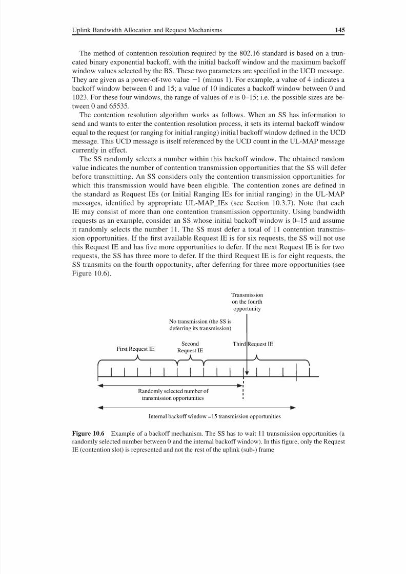
8/10/2019 WiMax-Tech for BBW Access
http://slidepdf.com/reader/full/wimax-tech-for-bbw-access 162/293
Uplink Bandwidth Allocation and Request Mechanisms 145
The method of contention resolution required by the 802.16 standard is based on a trun-
cated binary exponential backoff, with the initial backoff window and the maximum backoff
window values selected by the BS. These two parameters are specified in the UCD message.
They are given as a power-of-two value 1 (minus 1). For example, a value of 4 indicates a
backoff window between 0 and 15; a value of 10 indicates a backoff window between 0 and1023. For these four windows, the range of values of n is 0–15; i.e. the possible sizes are be-
tween 0 and 65535.
The contention resolution algorithm works as follows. When an SS has information to
send and wants to enter the contention resolution process, it sets its internal backoff window
equal to the request (or ranging for initial ranging) initial backoff window defined in the UCD
message. This UCD message is itself referenced by the UCD count in the UL-MAP message
currently in effect.
The SS randomly selects a number within this backoff window. The obtained random
value indicates the number of contention transmission opportunities that the SS will defer
before transmitting. An SS considers only the contention transmission opportunities forwhich this transmission would have been eligible. The contention zones are defined in
the standard as Request IEs (or Initial Ranging IEs for initial ranging) in the UL-MAP
messages, identified by appropriate UL-MAP_IEs (see Section 10.3.7). Note that each
IE may consist of more than one contention transmission opportunity. Using bandwidth
requests as an example, consider an SS whose initial backoff window is 0–15 and assume
it randomly selects the number 11. The SS must defer a total of 11 contention transmis-
sion opportunities. If the first available Request IE is for six requests, the SS will not use
this Request IE and has five more opportunities to defer. If the next Request IE is for two
requests, the SS has three more to defer. If the third Request IE is for eight requests, the
SS transmits on the fourth opportunity, after deferring for three more opportunities (see
Figure 10.6).
Randomly selected number of
transmission opportunities
First Request IE
No transmission (the SS is
deferring its transmission)
Transmission
on the fourth
opportunity
Second
Request IE
Third Request IE
Internal backoff window =15 transmission opportunities
Figure 10.6 Example of a backoff mechanism. The SS has to wait 11 transmission opportunities (arandomly selected number between 0 and the internal backoff window). In this figure, only the Request
IE (contention slot) is represented and not the rest of the uplink (sub-) frame
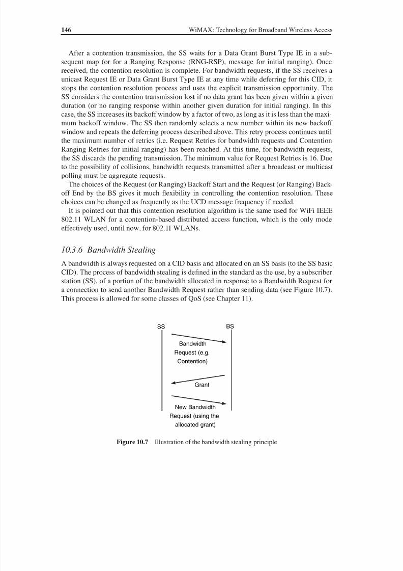
8/10/2019 WiMax-Tech for BBW Access
http://slidepdf.com/reader/full/wimax-tech-for-bbw-access 163/293
146 WiMAX: Technology for Broadband Wireless Access
After a contention transmission, the SS waits for a Data Grant Burst Type IE in a sub-
sequent map (or for a Ranging Response (RNG-RSP), message for initial ranging). Once
received, the contention resolution is complete. For bandwidth requests, if the SS receives a
unicast Request IE or Data Grant Burst Type IE at any time while deferring for this CID, it
stops the contention resolution process and uses the explicit transmission opportunity. TheSS considers the contention transmission lost if no data grant has been given within a given
duration (or no ranging response within another given duration for initial ranging). In this
case, the SS increases its backoff window by a factor of two, as long as it is less than the maxi-
mum backoff window. The SS then randomly selects a new number within its new backoff
window and repeats the deferring process described above. This retry process continues until
the maximum number of retries (i.e. Request Retries for bandwidth requests and Contention
Ranging Retries for initial ranging) has been reached. At this time, for bandwidth requests,
the SS discards the pending transmission. The minimum value for Request Retries is 16. Due
to the possibility of collisions, bandwidth requests transmitted after a broadcast or multicast
polling must be aggregate requests.The choices of the Request (or Ranging) Backoff Start and the Request (or Ranging) Back-
off End by the BS gives it much flexibility in controlling the contention resolution. These
choices can be changed as frequently as the UCD message frequency if needed.
It is pointed out that this contention resolution algorithm is the same used for WiFi IEEE
802.11 WLAN for a contention-based distributed access function, which is the only mode
effectively used, until now, for 802.11 WLANs.
10.3.6 Bandwidth Stealing
A bandwidth is always requested on a CID basis and allocated on an SS basis (to the SS basic
CID). The process of bandwidth stealing is defined in the standard as the use, by a subscriber
station (SS), of a portion of the bandwidth allocated in response to a Bandwidth Request for
a connection to send another Bandwidth Request rather than sending data (see Figure 10.7).
This process is allowed for some classes of QoS (see Chapter 11).
New Bandwidth
Request (using the
allocated grant)
Grant
Bandwidth
Request (e.g.
Contention)
BSSS
Figure 10.7 Illustration of the bandwidth stealing principle
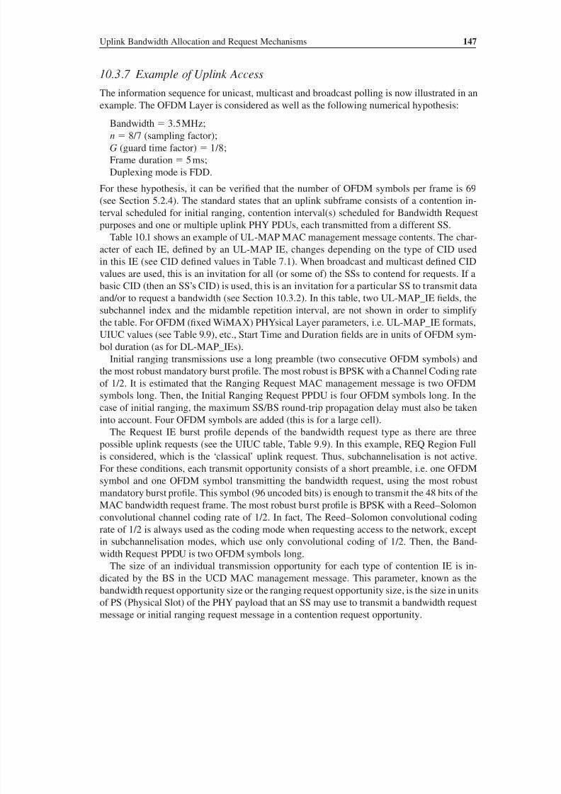
8/10/2019 WiMax-Tech for BBW Access
http://slidepdf.com/reader/full/wimax-tech-for-bbw-access 164/293
Uplink Bandwidth Allocation and Request Mechanisms 147
10.3.7 Example of Uplink Access
The information sequence for unicast, multicast and broadcast polling is now illustrated in an
example. The OFDM Layer is considered as well as the following numerical hypothesis:
Bandwidth 3.5 MHz;n 8/7 (sampling factor);
G (guard time factor) 1/8;
Frame duration 5 ms;
Duplexing mode is FDD.
For these hypothesis, it can be verified that the number of OFDM symbols per frame is 69
(see Section 5.2.4). The standard states that an uplink subframe consists of a contention in-
terval scheduled for initial ranging, contention interval(s) scheduled for Bandwidth Request
purposes and one or multiple uplink PHY PDUs, each transmitted from a different SS.
Table 10.1 shows an example of UL-MAP MAC management message contents. The char-acter of each IE, defined by an UL-MAP IE, changes depending on the type of CID used
in this IE (see CID defined values in Table 7.1). When broadcast and multicast defined CID
values are used, this is an invitation for all (or some of) the SSs to contend for requests. If a
basic CID (then an SS’s CID) is used, this is an invitation for a particular SS to transmit data
and/or to request a bandwidth (see Section 10.3.2). In this table, two UL-MAP_IE fields, the
subchannel index and the midamble repetition interval, are not shown in order to simplify
the table. For OFDM (fixed WiMAX) PHYsical Layer parameters, i.e. UL-MAP_IE formats,
UIUC values (see Table 9.9), etc., Start Time and Duration fields are in units of OFDM sym-
bol duration (as for DL-MAP_IEs).
Initial ranging transmissions use a long preamble (two consecutive OFDM symbols) andthe most robust mandatory burst profile. The most robust is BPSK with a Channel Coding rate
of 1/2. It is estimated that the Ranging Request MAC management message is two OFDM
symbols long. Then, the Initial Ranging Request PPDU is four OFDM symbols long. In the
case of initial ranging, the maximum SS/BS round-trip propagation delay must also be taken
into account. Four OFDM symbols are added (this is for a large cell).
The Request IE burst profile depends of the bandwidth request type as there are three
possible uplink requests (see the UIUC table, Table 9.9). In this example, REQ Region Full
is considered, which is the ‘classical’ uplink request. Thus, subchannelisation is not active.
For these conditions, each transmit opportunity consists of a short preamble, i.e. one OFDM
symbol and one OFDM symbol transmitting the bandwidth request, using the most robustmandatory burst profile. This symbol (96 uncoded bits) is enough to transmit the 48 bits of the
MAC bandwidth request frame. The most robust burst profile is BPSK with a Reed–Solomon
convolutional channel coding rate of 1/2. In fact, The Reed–Solomon convolutional coding
rate of 1/2 is always used as the coding mode when requesting access to the network, except
in subchannelisation modes, which use only convolutional coding of 1/2. Then, the Band-
width Request PPDU is two OFDM symbols long.
The size of an individual transmission opportunity for each type of contention IE is in-
dicated by the BS in the UCD MAC management message. This parameter, known as the
bandwidth request opportunity size or the ranging request opportunity size, is the size in units
of PS (Physical Slot) of the PHY payload that an SS may use to transmit a bandwidth requestmessage or initial ranging request message in a contention request opportunity.
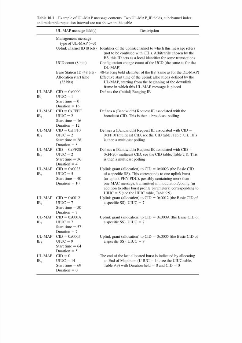
8/10/2019 WiMax-Tech for BBW Access
http://slidepdf.com/reader/full/wimax-tech-for-bbw-access 165/293
Table 10.1 Example of UL-MAP message contents. Two UL-MAP_IE fields, subchannel index
and midamble repetition interval are not shown in this table
UL-MAP message field(s) Description
Management message
type of UL-MAP (3)
Uplink channel ID (8 bits) Identifier of the uplink channel to which this message refers
(not to be confused with CID). Arbitrarily chosen by theBS, this ID acts as a local identifier for some transactions
UCD count (8 bits) Configuration change count of the UCD (the same as for the
DL-MAP)
Base Station ID (48 bits) 48-bit long field identifier of the BS (same as for the DL-MAP)
Allocation start time
(32 bits)
Effective start time of the uplink allocations defined by the
UL-MAP, starting from the beginning of the downlink
frame in which this UL-MAP message is placed
UL-MAP
IE1
CID 0x0000
UIUC 1
Start time 0
Duration 16
Defines the (Initial) Ranging IE
UL-MAP
IE2
CID 0xFFFF
UIUC 2
Start time 16
Duration 12
Defines a (Bandwidth) Request IE associated with the
broadcast CID. This is then a broadcast polling
UL-MAP
IE3
CID 0xFF10
UIUC 2
Start time 28
Duration 8
Defines a (Bandwidth) Request IE associated with CID
0xFF10 (multicast CID, see the CID table, Table 7.1). This
is then a multicast polling
UL-MAP
IE4
CID 0xFF20
UIUC
2Start time 36
Duration 4
Defines a (Bandwidth) Request IE associated with CID
0xFF20 (multicast CID, see the CID table, Table 7.1). Thisis then a multicast polling
UL-MAP
IE5
CID 0x0023
UIUC 5
Start time 40
Duration 10
Uplink grant (allocation) to CID 0x0023 (the Basic CID
of a specific SS). This corresponds to one uplink burst
(or uplink PHY PDU), possibly containing more than
one MAC message, transmitted in modulation/coding (in
addition to other burst profile parameters) corresponding to
UIUC 5 (see the UIUC table, Table 9.9)
UL-MAP
IE6
CID 0x0012
UIUC 7
Start time 50Duration 7
Uplink grant (allocation) to CID 0x0012 (the Basic CID of
a specific SS). UIUC 7
UL-MAP
IE7
CID 0x000A
UIUC 7
Start time 57
Duration 7
Uplink grant (allocation) to CID 0x000A (the Basic CID of
a specific SS). UIUC 7
UL-MAP
IE8
CID 0x0005
UIUC 9
Start time 64
Duration 5
Uplink grant (allocation) to CID 0x0005 (the Basic CID of
a specific SS). UIUC 9
UL-MAP
IE9
CID 0
UIUC 14Start time 69
Duration 0
The end of the last allocated burst is indicated by allocating
an End of Map burst (U IUC 14, see the UIUC table,Table 9.9) with Duration field 0 and CID 0

8/10/2019 WiMax-Tech for BBW Access
http://slidepdf.com/reader/full/wimax-tech-for-bbw-access 166/293
Uplink Bandwidth Allocation and Request Mechanisms 149
The PS is the basic unit of time. A PS corresponds to four (modulation) symbols used on
the transmission channel (for OFDM and OFDMA PHY layers). The individual transmission
opportunity (the bandwidth request opportunity size or the ranging request opportunity size)
includes all PHY overheads as well as allowance for the MAC data the message may hold. It
is assumed for this example that:
• The initial ranging request opportunity size, indicated by the UCD MAC management
message, is equal to eight OFDM symbols. The initial ranging IE (contention slots), indi-
cated by the UL-MAP MAC management message is 16 symbols long (see Table 10.1).
• The bandwidth request opportunity size, indicated by the UCD MAC management mes-
sage, is equal to two OFDM symbols (see Figure 10.8). The Bandwidth Request IE (conten-
tion slots), indicated by the UL-MAP MAC management message, is 12 symbols long (see
Table 10.1). These numerical values are used for the uplink frame figure.
It can be verified that the length of a bandwidth request opportunity size or the ranging
request opportunity size (in PS, as indicated in the UCD message) is 144 PS (two OFDM
symbols).
The duration field in UL-MAP_IE indicates the duration, in units of OFDM symbols, of
the allocation. This value includes the preamble, the (possible) midambles and the postamble
contained in the allocation. In the example given in this section, it is assumed that there is no
midamble; i.e. the midamble repetition interval field (2 bits) in the beginning of the UL_MAP
message (see Chapter 9 for the UL-MAP) is equal to 0b00. The standard indicates that all SSs
must acquire and adjust their timing such that all uplink OFDM symbols arrive time coinci-
dent at the BS with an accuracy of ±50 % of the minimum guard interval or better. Figure 10.9
shows the uplink bursts in the uplink subframe described by the UL-MAP in Table 10.1.
Assuming that the Modulation and Coding Scheme (MCS) corresponding to UIUC 7
is 16-QAM, 3/4, estimate the uplink data rate of the SS with Basic CID 0x000A (on the
duration of the considered frame)? Consider that this allocation is made once every four
Bandwidth requestopportunity
(2 OFDM Symbols,144 PS)
Preamble
(1 OFDM Symbol)
Bandwidth Request MACManagement Message
(1 OFDM Symbol)
Bandwidth Request IE = Bandwidth Request Contention Slots zone(12 OFDM Symbols)
Bandwidth requestopportunity
(2 OFDM Symbols,144 PS)
Bandwidth requestopportunity
(2 OFDM Symbols,144 PS)
Figure 10.8 Example of Bandwidth Request IE (bandwidth request contention slots). The BS must al-
locate a bandwidth for Bandwidth Request IE in integer multiples of individual transmission opportunity
values (indicated in the UCD message)
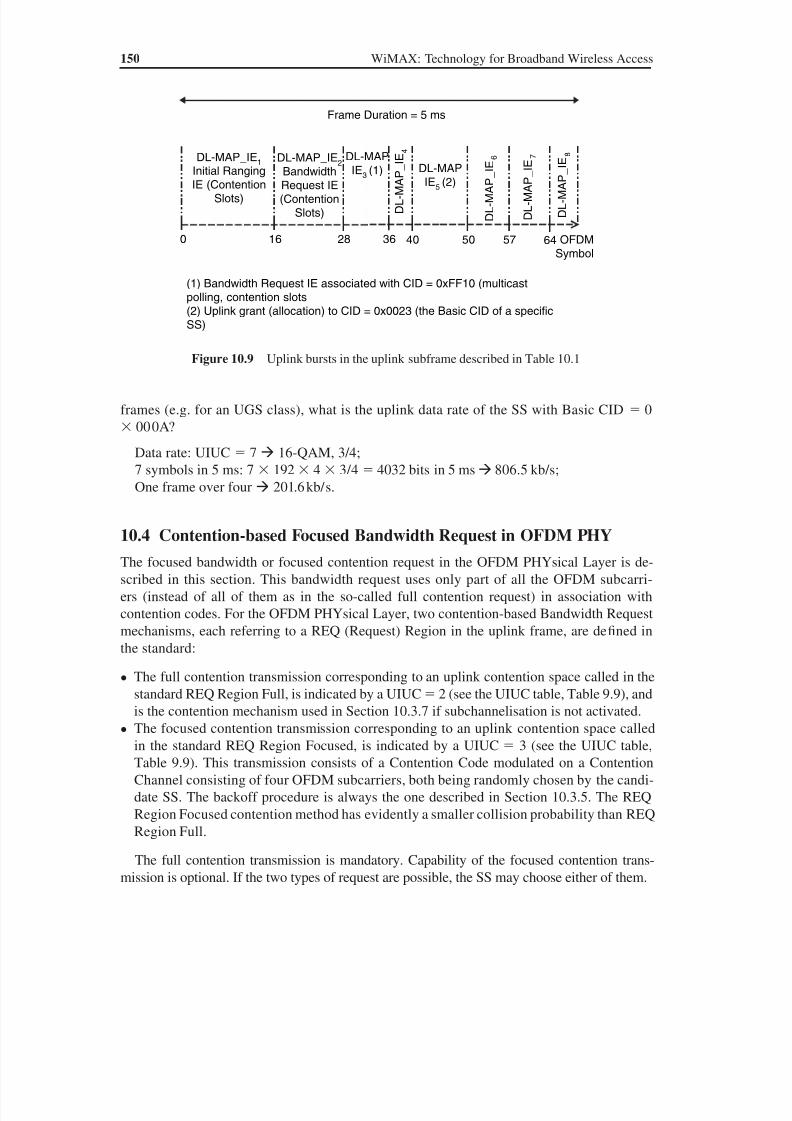
8/10/2019 WiMax-Tech for BBW Access
http://slidepdf.com/reader/full/wimax-tech-for-bbw-access 167/293
150 WiMAX: Technology for Broadband Wireless Access
frames (e.g. for an UGS class), what is the uplink data rate of the SS with Basic CID 0
000A?
Data rate: UIUC 7 16-QAM, 3/4;
7 symbols in 5 ms: 7 192 4 3/4 4032 bits in 5 ms 806.5 kb/s;
One frame over four 201.6 kb/s.
10.4 Contention-based Focused Bandwidth Request in OFDM PHY
The focused bandwidth or focused contention request in the OFDM PHYsical Layer is de-
scribed in this section. This bandwidth request uses only part of all the OFDM subcarri-
ers (instead of all of them as in the so-called full contention request) in association with
contention codes. For the OFDM PHYsical Layer, two contention-based Bandwidth Request
mechanisms, each referring to a REQ (Request) Region in the uplink frame, are defined in
the standard:
• The full contention transmission corresponding to an uplink contention space called in thestandard REQ Region Full, is indicated by a UIUC 2 (see the UIUC table, Table 9.9), and
is the contention mechanism used in Section 10.3.7 if subchannelisation is not activated.
• The focused contention transmission corresponding to an uplink contention space called
in the standard REQ Region Focused, is indicated by a UIUC 3 (see the UIUC table,
Table 9.9). This transmission consists of a Contention Code modulated on a Contention
Channel consisting of four OFDM subcarriers, both being randomly chosen by the candi-
date SS. The backoff procedure is always the one described in Section 10.3.5. The REQ
Region Focused contention method has evidently a smaller collision probability than REQ
Region Full.
The full contention transmission is mandatory. Capability of the focused contention trans-
mission is optional. If the two types of request are possible, the SS may choose either of them.
Frame Duration = 5 ms
OFDMSymbol
0 16 28 36 40 50 57 64
DL-MAP_IE1
Initial RangingIE (Contention
Slots)
DL-MAP_IE2
BandwidthRequest IE(Contention
Slots)
(1) Bandwidth Request IE associated with CID = 0xFF10 (multicastpolling, contention slots(2) Uplink grant (allocation) to CID = 0x0023 (the Basic CID of a specificSS)
DL-MAP
IE3 (1)
E I
_ P A M - L D
4
DL-MAPIE
5(2)
6
E I_ P A M - L D
E
I_ P A M - L D
7 E I_ P
A M - L D
8
Figure 10.9 Uplink bursts in the uplink subframe described in Table 10.1
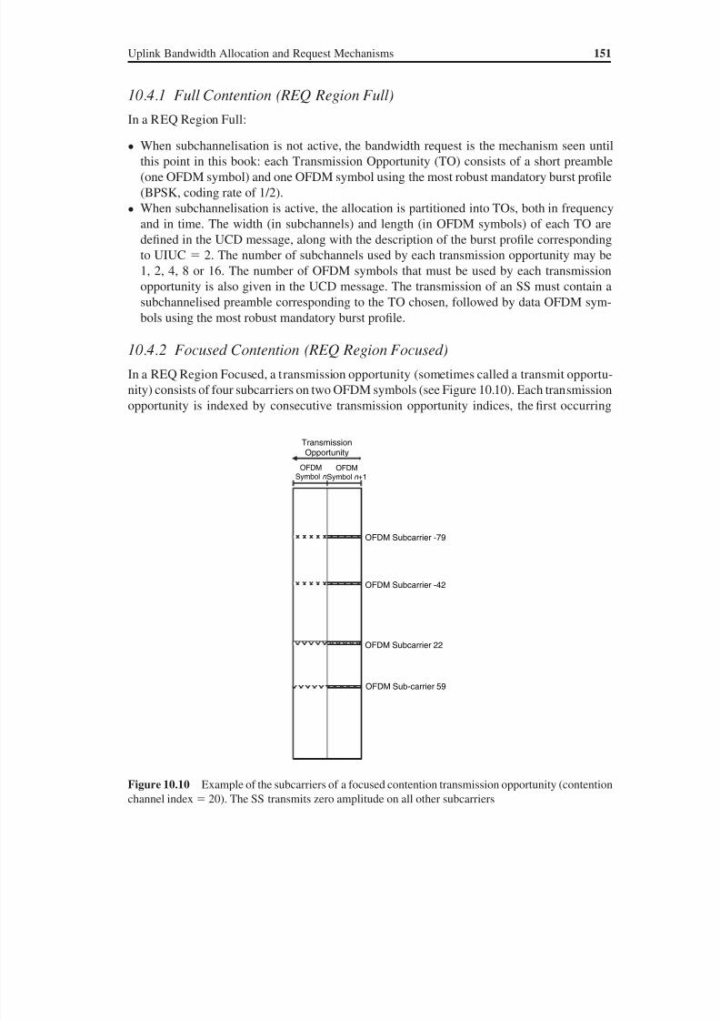
8/10/2019 WiMax-Tech for BBW Access
http://slidepdf.com/reader/full/wimax-tech-for-bbw-access 168/293
Uplink Bandwidth Allocation and Request Mechanisms 151
10.4.1 Full Contention (REQ Region Full)
In a REQ Region Full:
• When subchannelisation is not active, the bandwidth request is the mechanism seen until
this point in this book: each Transmission Opportunity (TO) consists of a short preamble
(one OFDM symbol) and one OFDM symbol using the most robust mandatory burst profile
(BPSK, coding rate of 1/2).
• When subchannelisation is active, the allocation is partitioned into TOs, both in frequency
and in time. The width (in subchannels) and length (in OFDM symbols) of each TO are
defined in the UCD message, along with the description of the burst profile corresponding
to UIUC 2. The number of subchannels used by each transmission opportunity may be
1, 2, 4, 8 or 16. The number of OFDM symbols that must be used by each transmission
opportunity is also given in the UCD message. The transmission of an SS must contain a
subchannelised preamble corresponding to the TO chosen, followed by data OFDM sym-
bols using the most robust mandatory burst profile.
10.4.2 Focused Contention (REQ Region Focused)
In a REQ Region Focused, a transmission opportunity (sometimes called a transmit opportu-
nity) consists of four subcarriers on two OFDM symbols (see Figure 10.10). Each transmission
opportunity is indexed by consecutive transmission opportunity indices, the first occurring
OFDMSymbol n
OFDMSymbol n +1
OFDM Subcarrier -79
OFDM Subcarrier -42
OFDM Subcarrier 22
OFDM Sub-carrier 59
TransmissionOpportunity
Figure 10.10 Example of the subcarriers of a focused contention transmission opportunity (contention
channel index 20). The SS transmits zero amplitude on all other subcarriers
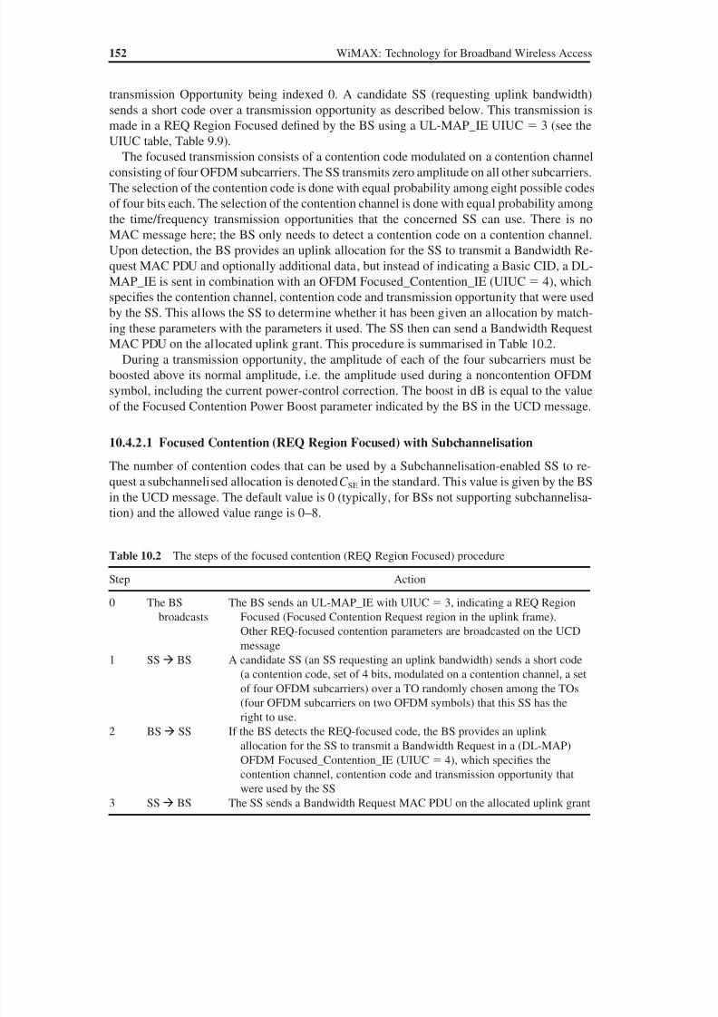
8/10/2019 WiMax-Tech for BBW Access
http://slidepdf.com/reader/full/wimax-tech-for-bbw-access 169/293
152 WiMAX: Technology for Broadband Wireless Access
transmission Opportunity being indexed 0. A candidate SS (requesting uplink bandwidth)
sends a short code over a transmission opportunity as described below. This transmission is
made in a REQ Region Focused defined by the BS using a UL-MAP_IE UIUC 3 (see the
UIUC table, Table 9.9).
The focused transmission consists of a contention code modulated on a contention channelconsisting of four OFDM subcarriers. The SS transmits zero amplitude on all other subcarriers.
The selection of the contention code is done with equal probability among eight possible codes
of four bits each. The selection of the contention channel is done with equal probability among
the time/frequency transmission opportunities that the concerned SS can use. There is no
MAC message here; the BS only needs to detect a contention code on a contention channel.
Upon detection, the BS provides an uplink allocation for the SS to transmit a Bandwidth Re-
quest MAC PDU and optionally additional data, but instead of indicating a Basic CID, a DL-
MAP_IE is sent in combination with an OFDM Focused_Contention_IE (UIUC 4), which
specifies the contention channel, contention code and transmission opportunity that were used
by the SS. This allows the SS to determine whether it has been given an allocation by match-ing these parameters with the parameters it used. The SS then can send a Bandwidth Request
MAC PDU on the allocated uplink grant. This procedure is summarised in Table 10.2.
During a transmission opportunity, the amplitude of each of the four subcarriers must be
boosted above its normal amplitude, i.e. the amplitude used during a noncontention OFDM
symbol, including the current power-control correction. The boost in dB is equal to the value
of the Focused Contention Power Boost parameter indicated by the BS in the UCD message.
10.4.2.1 Focused Contention (REQ Region Focused) with Subchannelisation
The number of contention codes that can be used by a Subchannelisation-enabled SS to re-quest a subchannelised allocation is denoted CSE in the standard. This value is given by the BS
in the UCD message. The default value is 0 (typically, for BSs not supporting subchannelisa-
tion) and the allowed value range is 0–8.
Table 10.2 The steps of the focused contention (REQ Region Focused) procedure
Step Action
0 The BS
broadcasts
The BS sends an UL-MAP_IE with UIUC 3, indicating a REQ Region
Focused (Focused Contention Request region in the uplink frame).Other REQ-focused contention parameters are broadcasted on the UCD
message
1 SS BS A candidate SS (an SS requesting an uplink bandwidth) sends a short code
(a contention code, set of 4 bits, modulated on a contention channel, a set
of four OFDM subcarriers) over a TO randomly chosen among the TOs
(four OFDM subcarriers on two OFDM symbols) that this SS has the
right to use.
2 BS SS If the BS detects the REQ-focused code, the BS provides an uplink
allocation for the SS to transmit a Bandwidth Request in a (DL-MAP)
OFDM Focused_Contention_IE (UIUC 4), which specifies the
contention channel, contention code and transmission opportunity thatwere used by the SS
3 SS BS The SS sends a Bandwidth Request MAC PDU on the allocated uplink grant
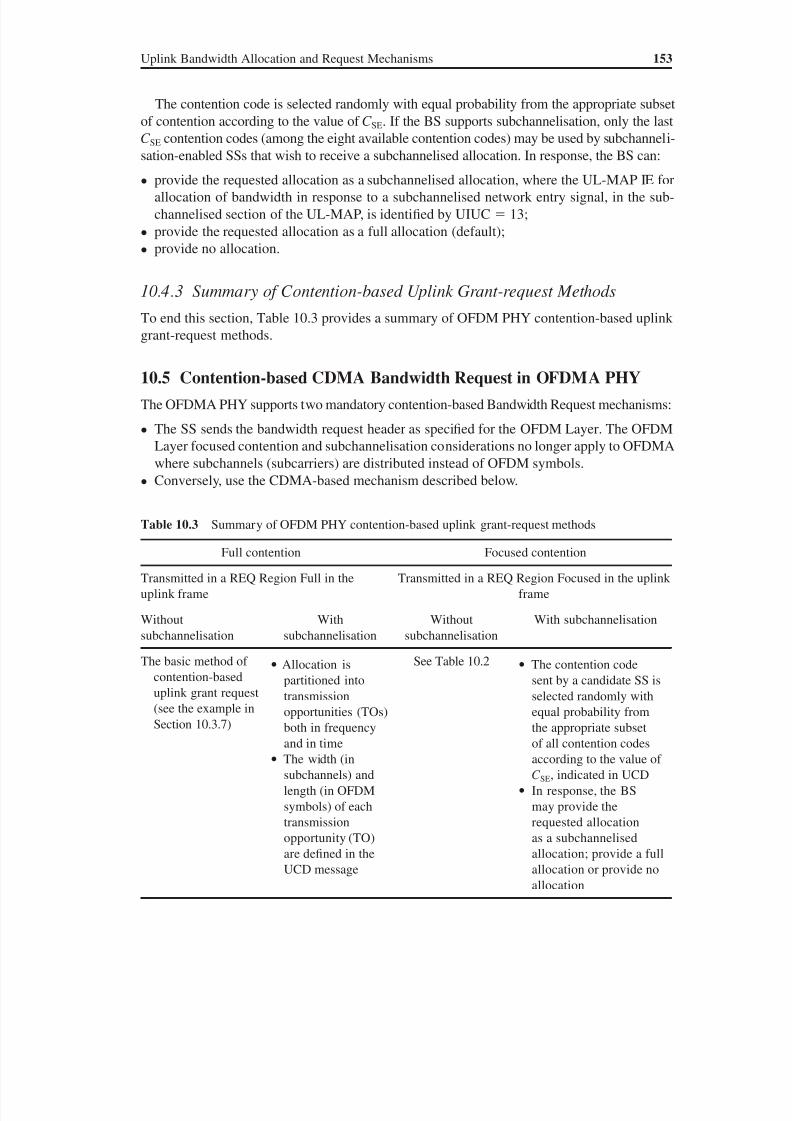
8/10/2019 WiMax-Tech for BBW Access
http://slidepdf.com/reader/full/wimax-tech-for-bbw-access 170/293
Uplink Bandwidth Allocation and Request Mechanisms 153
The contention code is selected randomly with equal probability from the appropriate subset
of contention according to the value of CSE. If the BS supports subchannelisation, only the last
CSE contention codes (among the eight available contention codes) may be used by subchanneli-
sation-enabled SSs that wish to receive a subchannelised allocation. In response, the BS can:
• provide the requested allocation as a subchannelised allocation, where the UL-MAP IE for
allocation of bandwidth in response to a subchannelised network entry signal, in the sub-
channelised section of the UL-MAP, is identified by UIUC 13;
• provide the requested allocation as a full allocation (default);
• provide no allocation.
10.4.3 Summary of Contention-based Uplink Grant-request Methods
To end this section, Table 10.3 provides a summary of OFDM PHY contention-based uplink
grant-request methods.
10.5 Contention-based CDMA Bandwidth Request in OFDMA PHY
The OFDMA PHY supports two mandatory contention-based Bandwidth Request mechanisms:
• The SS sends the bandwidth request header as specified for the OFDM Layer. The OFDM
Layer focused contention and subchannelisation considerations no longer apply to OFDMA
where subchannels (subcarriers) are distributed instead of OFDM symbols.
• Conversely, use the CDMA-based mechanism described below.
Table 10.3 Summary of OFDM PHY contention-based uplink grant-request methods
Full contention Focused contention
Transmitted in a REQ Region Full in the
uplink frame
Transmitted in a REQ Region Focused in the uplink
frame
Without
subchannelisation
With
subchannelisation
Without
subchannelisation
With subchannelisation
The basic method of
contention-baseduplink grant request
(see the example in
Section 10.3.7)
• Allocation is
partitioned intotransmission
opportunities (TOs)
both in frequency
and in time
• The width (in
subchannels) and
length (in OFDM
symbols) of each
transmission
opportunity (TO)
are defined in theUCD message
See Table 10.2 • The contention code
sent by a candidate SS isselected randomly with
equal probability from
the appropriate subset
of all contention codes
according to the value of
CSE, indicated in UCD
• In response, the BS
may provide the
requested allocation
as a subchannelised
allocation; provide a fullallocation or provide no
allocation
8/10/2019 WiMax-Tech for BBW Access
http://slidepdf.com/reader/full/wimax-tech-for-bbw-access 171/293

8/10/2019 WiMax-Tech for BBW Access
http://slidepdf.com/reader/full/wimax-tech-for-bbw-access 172/293
11Network Entry and Qualityof Service (QoS) Management
11.1 Ranging
The ranging process is defined in the 802.16 standard as the process that allows the SSs to:
• Acquire the correct timing offset of the network. The SS can then be aligned with the frame
received from the BS (for OFDM and OFDMA PHYsical layers).
• Request power adjustments and/or downlink burst profile change. The SS can then be
received within the appropriate reception thresholds.
The SS realises ranging by transmitting the RNG-REQ MAC management message. The
RNG-REQ message may be sent in the initial ranging uplink contention slots (see Chapter 10)
or in data grant intervals allocated by the BS to the SS. Ranging is made by the SS at initiali-
sation and periodically. This gives two types of ranging processes:
• the initial ranging;
• the periodic ranging (sometimes simply known as ranging).
In the OFDM PHYsical Layer, initial ranging uses the initial ranging uplink contention
slots while the periodic ranging uses the regular (allocated uplink grant) bursts. The initial
ranging procedure is a part of the network entry process described in Section 11.6.
11.1.1 Ranging MessagesTwo MAC management messages are used for initial ranging: the Ranging Request (RNG-REQ)
message and the Ranging Response (RNG-RSP) message. These messages are now detailed.
The Ranging Request (RNG-REQ) message is transmitted by the SS at initialisation. It
can also be used at other periods to determine network delay and to request power and/or
downlink burst profile change. The CID field value in the MAC header of the RNG-REQ
message contains the following:
• Initial ranging CID (0x0000) if the SS is attempting to join the network or if the SS has not
yet registered and is changing downlink (or both downlink and uplink) channels.
WiMAX: Technology for Broadband Wireless Access Loutfi Nuaymi
© 2007 John Wiley & Sons, Ltd. ISBN: 0-470-02808-4
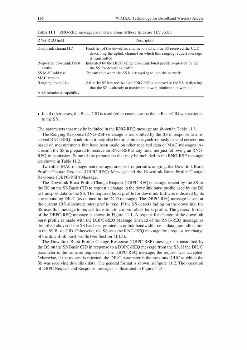
8/10/2019 WiMax-Tech for BBW Access
http://slidepdf.com/reader/full/wimax-tech-for-bbw-access 173/293
156 WiMAX: Technology for Broadband Wireless Access
• In all other cases, the Basic CID is used (other cases assume that a Basic CID was assigned
to the SS).
The parameters that may be included in the RNG-REQ message are shown in Table 11.1.
The Ranging Response (RNG-RSP) message is transmitted by the BS in response to a re-
ceived RNG-REQ. In addition, it may also be transmitted asynchronously to send corrections
based on measurements that have been made on other received data or MAC messages. As
a result, the SS is prepared to receive an RNG-RSP at any time, not just following an RNG-
REQ transmission. Some of the parameters that may be included in the RNG-RSP message
are shown in Table 11.2.
Two other MAC management messages are used for periodic ranging: the Downlink Burst
Profile Change Request (DBPC-REQ) Message and the Downlink Burst Profile Change
Response (DBPC-RSP) Message.
The Downlink Burst Profile Change Request (DBPC-REQ) message is sent by the SS to
the BS on the SS Basic CID to request a change in the downlink burst profile used by the BS
to transport data to the SS. The required burst profile for downlink traffic is indicated by its
corresponding DIUC (as defined in the DCD message). The DBPC-REQ message is sent at
the current (BS allocated) burst profile type. If the SS detects fading on the downlink, the
SS uses this message to request transition to a more robust burst profile. The general format
of the DBPC-REQ message is shown in Figure 11.1. A request for change of the downlink
burst profile is made with the DBPC-REQ Message (instead of the RNG-REQ message as
described above) if the SS has been granted an uplink bandwidth, i.e. a data grant allocation
to the SS Basic CID. Otherwise, the SS uses the RNG-REQ message for a request for change
of the downlink burst profile (see Section 11.1.3).
The Downlink Burst Profile Change Response (DBPC-RSP) message is transmitted by
the BS on the SS Basic CID in response to a DBPC-REQ message from the SS. If the DIUC
parameter is the same as requested in the DBPC-REQ message, the request was accepted.
Otherwise, if the request is rejected, the DIUC parameter is the previous DIUC at which the
SS was receiving downlink data. The general format is shown in Figure 11.2. The operation
of DBPC Request and Response messages is illustrated in Figure 11.3.
Table 11.1 RNG-REQ message parameters. Some of these fields are TLV coded
RNG-REQ field Description
Downlink channel ID Identifier of the downlink channel on which the SS received the UCD
describing the uplink channel on which this ranging request messageis transmitted
Requested downlink burst
profile
Indicated by the DIUC of the downlink burst profile requested by the
the SS for downlink traffic
SS MAC address Transmitted when the SS is attempting to join the network
MAC version
Ranging anomalies After the SS has received an RNG-RSP addressed to the SS, indicating
that the SS is already at maximum power, minimum power, etc.
AAS broadcast capability

8/10/2019 WiMax-Tech for BBW Access
http://slidepdf.com/reader/full/wimax-tech-for-bbw-access 174/293
Network Entry and Quality of Service (QoS) Management 157
Table 11.2 Some of the parameters of the RNG-RSP message. Some of these fields
are TLV coded
RNG-RSP field Description
Ranging status Indicates whether uplink messages are received withinacceptable limits by BS. This field is mandatory. Possible
values are 1 continue, 2 abort, 3 success, 4 rerange
Timing adjust The time required to advance the SS transmission to enable
frames to arrive at the expected time instance at the
BS. Units are PHYsical Layer specific. For the OFDM
(WiMAX) PHYsical Layer, the unit is the symbol duration
1/ f s). If this field is not included, no time adjustment is to be
made
Power adjust Transmitted power offset adjustment (signed 8-bit, in 0.25 dB
units). This field specifies the relative change in the
transmission power level that the SS must make in order fortransmissions to arrive at the BS at the desired power. If this
field is not included, no power adjustment is to be made
Offset frequency adjust Transmitted frequency offset adjustment (signed 32-bit,
Hz units). This field specifies the relative change in
transmission frequency that the SS must make in order to
better match the BS. This is a fine-frequency adjustment
within a channel, not reassignment to a different channel
Basic CID Assigned by the BS at initial access. In this case, the RNG-
RSP message is being sent on the initial ranging CID in
response to an RNG-REQ message that was itself sent on
the initial ranging CID
Primary management CID Assigned by the BS at initial access, in the same conditions as
the Basic CID
MAC address SS MAC address (48-bit)
Downlink operational
burst profile
Specifies the least robust DIUC that may be used by the BS for
transmissions to the SS
Frame number In which the corresponding RNG-REQ message (for OFDM/
WiMAX) was received. When the frame number is
included, the SS MAC address does not appear in the same
message
Ranging subchannel The OFDM ranging subchannel index that was used totransmit the initial ranging message
AAS broadcast permission
DIUCReservedManagement
message type (=23)Configurationchange count
Figure 11.1 DBPC-REQ MAC management message format. The required burst profile for downlinktraffic is indicated by its corresponding DIUC (as defined in the DCD message)
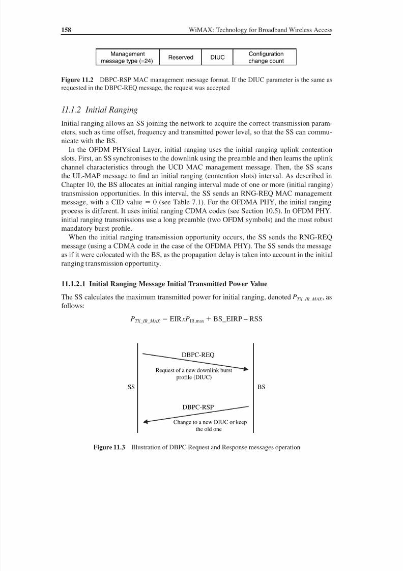
8/10/2019 WiMax-Tech for BBW Access
http://slidepdf.com/reader/full/wimax-tech-for-bbw-access 175/293
158 WiMAX: Technology for Broadband Wireless Access
11.1.2 Initial Ranging
Initial ranging allows an SS joining the network to acquire the correct transmission param-
eters, such as time offset, frequency and transmitted power level, so that the SS can commu-
nicate with the BS.
In the OFDM PHYsical Layer, initial ranging uses the initial ranging uplink contention
slots. First, an SS synchronises to the downlink using the preamble and then learns the uplink
channel characteristics through the UCD MAC management message. Then, the SS scans
the UL-MAP message to find an initial ranging (contention slots) interval. As described in
Chapter 10, the BS allocates an initial ranging interval made of one or more (initial ranging)
transmission opportunities. In this interval, the SS sends an RNG-REQ MAC management
message, with a CID value 0 (see Table 7.1). For the OFDMA PHY, the initial ranging
process is different. It uses initial ranging CDMA codes (see Section 10.5). In OFDM PHY,
initial ranging transmissions use a long preamble (two OFDM symbols) and the most robust
mandatory burst profile.
When the initial ranging transmission opportunity occurs, the SS sends the RNG-REQ
message (using a CDMA code in the case of the OFDMA PHY). The SS sends the message
as if it were colocated with the BS, as the propagation delay is taken into account in the initial
ranging transmission opportunity.
11.1.2.1 Initial Ranging Message Initial Transmitted Power Value
The SS calculates the maximum transmitted power for initial ranging, denoted PTX _ IR_ MAX , as
follows:
PTX _ IR_ MAX EIR xPIR,max BS_EIRP – RSS
DIUCReservedManagement
message type (=24)Configurationchange count
Figure 11.2 DBPC-RSP MAC management message format. If the DIUC parameter is the same as
requested in the DBPC-REQ message, the request was accepted
DBPC-REQ
SS BS
DBPC-RSP
Request of a new downlink burst
profile (DIUC)
Change to a new DIUC or keep
the old one
Figure 11.3 Illustration of DBPC Request and Response messages operation
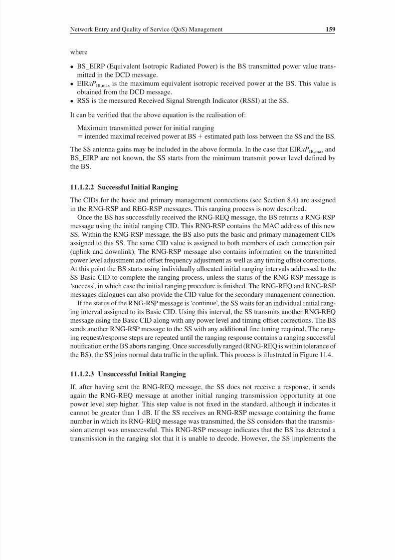
8/10/2019 WiMax-Tech for BBW Access
http://slidepdf.com/reader/full/wimax-tech-for-bbw-access 176/293
Network Entry and Quality of Service (QoS) Management 159
where
• BS_EIRP (Equivalent Isotropic Radiated Power) is the BS transmitted power value trans-
mitted in the DCD message.
• EIR xPIR,max is the maximum equivalent isotropic received power at the BS. This value isobtained from the DCD message.
• RSS is the measured Received Signal Strength Indicator (RSSI) at the SS.
It can be verified that the above equation is the realisation of:
Maximum transmitted power for initial ranging
intended maximal received power at BS estimated path loss between the SS and the BS.
The SS antenna gains may be included in the above formula. In the case that EIR xPIR,max and
BS_EIRP are not known, the SS starts from the minimum transmit power level defined by
the BS.
11.1.2.2 Successful Initial Ranging
The CIDs for the basic and primary management connections (see Section 8.4) are assigned
in the RNG-RSP and REG-RSP messages. This ranging process is now described.
Once the BS has successfully received the RNG-REQ message, the BS returns a RNG-RSP
message using the initial ranging CID. This RNG-RSP contains the MAC address of this new
SS. Within the RNG-RSP message, the BS also puts the basic and primary management CIDs
assigned to this SS. The same CID value is assigned to both members of each connection pair
(uplink and downlink). The RNG-RSP message also contains information on the transmittedpower level adjustment and offset frequency adjustment as well as any timing offset corrections.
At this point the BS starts using individually allocated initial ranging intervals addressed to the
SS Basic CID to complete the ranging process, unless the status of the RNG-RSP message is
‘success’, in which case the initial ranging procedure is finished. The RNG-REQ and RNG-RSP
messages dialogues can also provide the CID value for the secondary management connection.
If the status of the RNG-RSP message is ‘continue’, the SS waits for an individual initial rang-
ing interval assigned to its Basic CID. Using this interval, the SS transmits another RNG-REQ
message using the Basic CID along with any power level and timing offset corrections. The BS
sends another RNG-RSP message to the SS with any additional fine tuning required. The rang-
ing request/response steps are repeated until the ranging response contains a ranging successfulnotification or the BS aborts ranging. Once successfully ranged (RNG-REQ is within tolerance of
the BS), the SS joins normal data traf fic in the uplink. This process is illustrated in Figure 11.4.
11.1.2.3 Unsuccessful Initial Ranging
If, after having sent the RNG-REQ message, the SS does not receive a response, it sends
again the RNG-REQ message at another initial ranging transmission opportunity at one
power level step higher. This step value is not fixed in the standard, although it indicates it
cannot be greater than 1 dB. If the SS receives an RNG-RSP message containing the frame
number in which its RNG-REQ message was transmitted, the SS considers that the transmis-
sion attempt was unsuccessful. This RNG-RSP message indicates that the BS has detected a
transmission in the ranging slot that it is unable to decode. However, the SS implements the
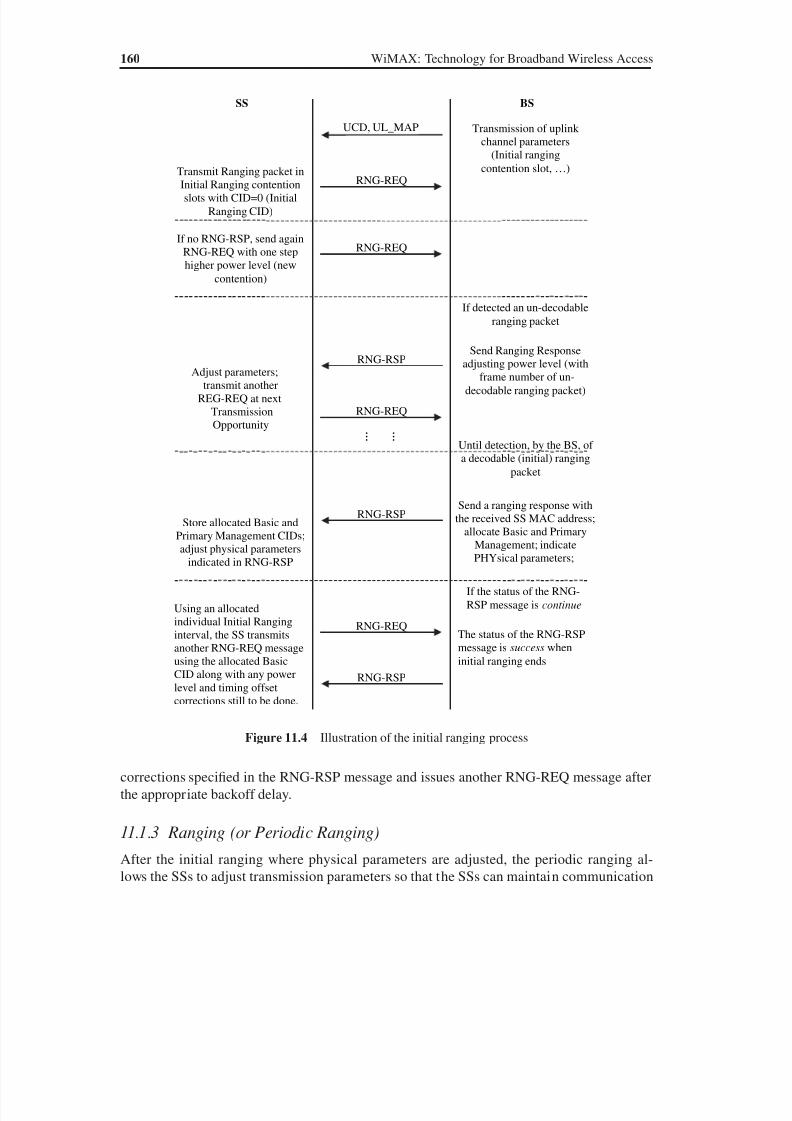
8/10/2019 WiMax-Tech for BBW Access
http://slidepdf.com/reader/full/wimax-tech-for-bbw-access 177/293
160 WiMAX: Technology for Broadband Wireless Access
corrections specified in the RNG-RSP message and issues another RNG-REQ message after
the appropriate backoff delay.
11.1.3 Ranging (or Periodic Ranging)
After the initial ranging where physical parameters are adjusted, the periodic ranging al-
lows the SSs to adjust transmission parameters so that the SSs can maintain communication
UCD, UL_MAP Transmission of uplink
channel parameters
(Initial ranging
contention slot, …)
SS BS
RNG-REQTransmit Ranging packet inInitial Ranging contention
slots with CID=0 (Initial
Ranging CID)
RNG-RSPSend Ranging Response
adjusting power level (with
frame number of un-
decodable ranging packet)
If detected an un-decodable
ranging packet
RNG-REQ
… …
Adjust parameters;
transmit another
REG-REQ at next
Transmission
Opportunity
RNG-RSP Send a ranging response withthe received SS MAC address;
allocate Basic and Primary
Management; indicate
PHYsical parameters;
Until detection, by the BS, of
a decodable (initial) ranging
packet
Store allocated Basic and
Primary Management CIDs;
adjust physical parameters
indicated in RNG-RSP
RNG-REQIf no RNG-RSP, send again
RNG-REQ with one step
higher power level (new
contention)
RNG-RSP
The status of the RNG-RSP
message is success when
initial ranging ends
If the status of the RNG-
RSP message is continue
RNG-REQ
Using an allocated
individual Initial Ranging
interval, the SS transmits
another RNG-REQ message
using the allocated Basic
CID along with any power
level and timing offset
corrections still to be done.
Figure 11.4 Illustration of the initial ranging process
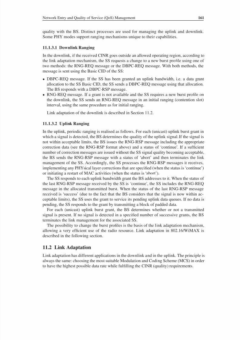
8/10/2019 WiMax-Tech for BBW Access
http://slidepdf.com/reader/full/wimax-tech-for-bbw-access 178/293
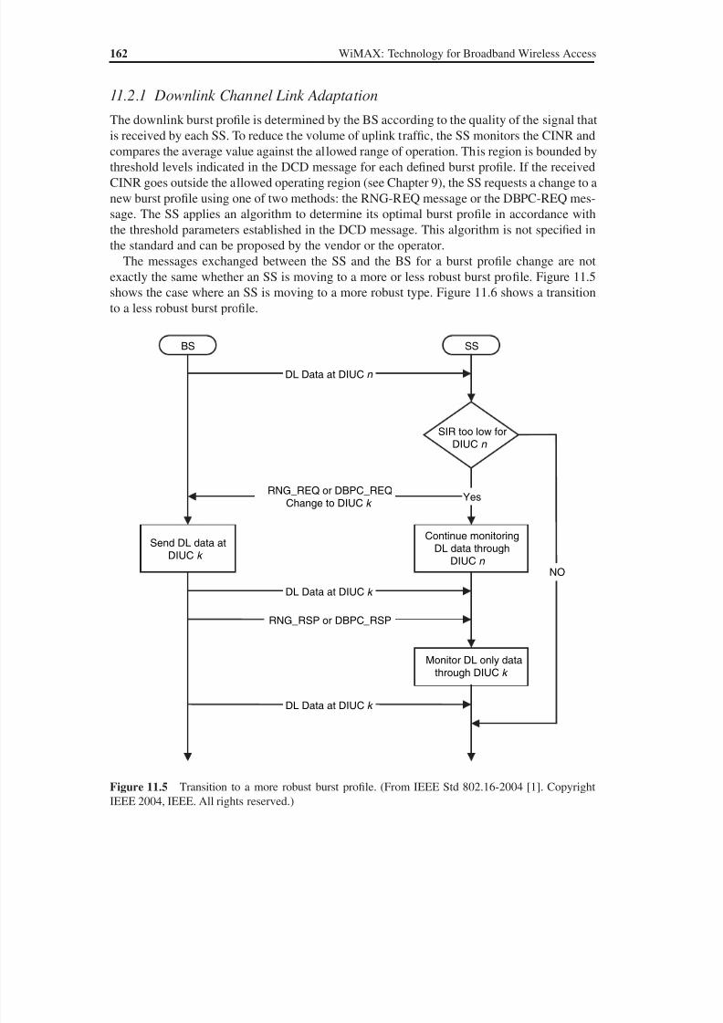
8/10/2019 WiMax-Tech for BBW Access
http://slidepdf.com/reader/full/wimax-tech-for-bbw-access 179/293
8/10/2019 WiMax-Tech for BBW Access
http://slidepdf.com/reader/full/wimax-tech-for-bbw-access 180/293
Network Entry and Quality of Service (QoS) Management 163
11.2.2 Uplink Channel Link Adaptation
In the uplink, the burst profile is also (as for the downlink) decided by the BS. The RNG-RSPMessage is used for that purpose as described in Section 11.1.3.
11.3 The Five Scheduling Services or QoS Classes
The IEEE 802.16 standard provides powerful tools in order to achieve different QoS con-
straints. The 802.16 standard MAC Layer provides QoS differentiation for the different types
of applications that might operate over 802.16 networks, through five defined scheduling ser-
vice types, also called QoS classes.
This classification into these scheduling service classes facilitates bandwidth sharing be-
tween different users. Every user has a quality of scheduling service class, also known as
QoS class. According to this parameter, the BS scheduler allocates the necessary amount
BS SS
DL Data at DIUC n
SIRhigh enough for
DIUC m
Yes
Start monitoringDL data through
DIUC m
Send DL data atDIUC m
RNG_REQ or DBPC_REQChange to DIUC m
RNG RSP or DBPC RSP_ _
DL Data at DIUC m
NO
Figure 11.6 Transition to a less robust burst profile. (From IEEE Std 802.16-2004 [1]. Copyright IEEE
2004, IEEE. All rights reserved.)
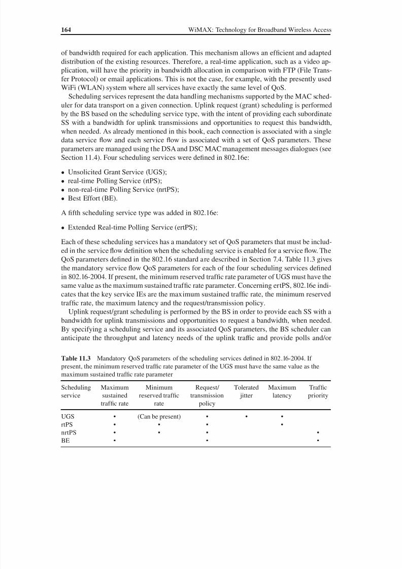
8/10/2019 WiMax-Tech for BBW Access
http://slidepdf.com/reader/full/wimax-tech-for-bbw-access 181/293
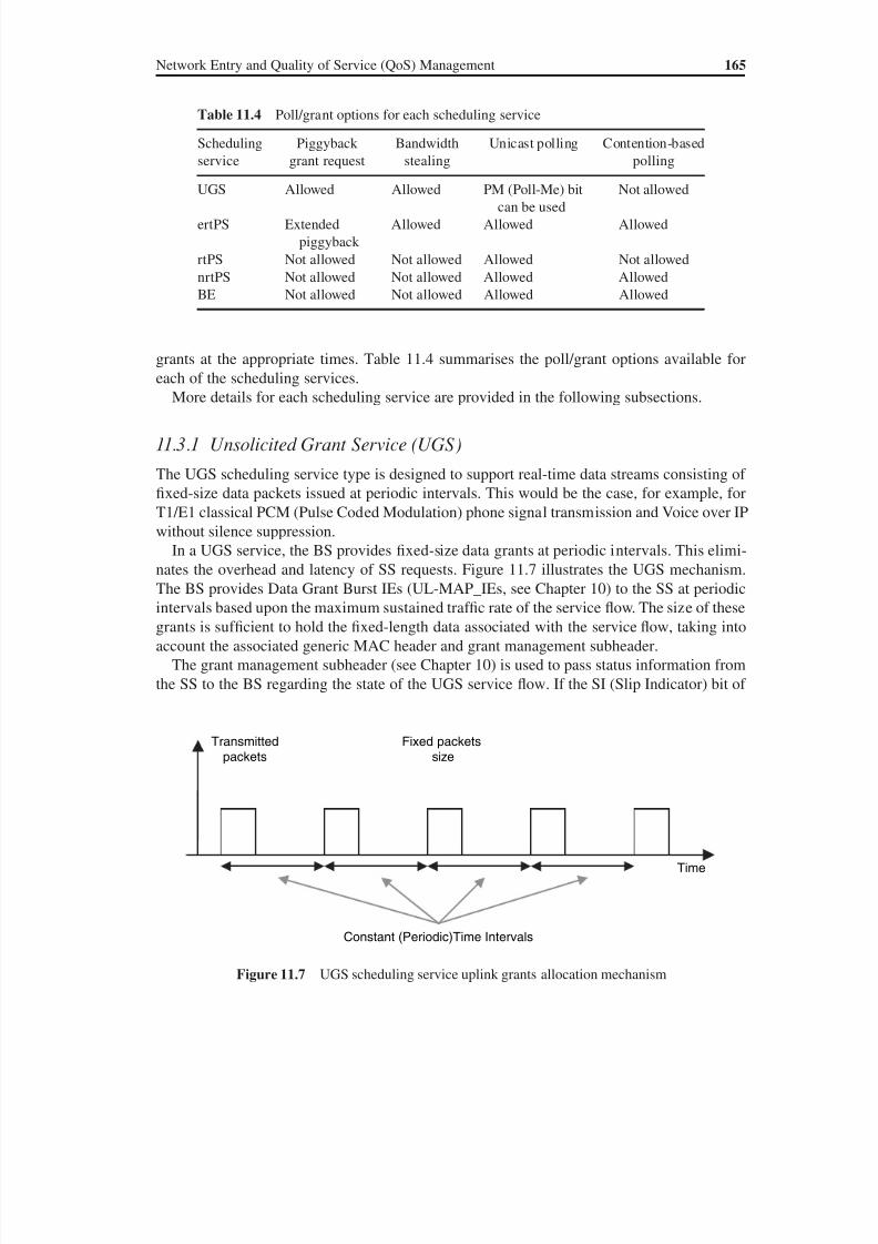
8/10/2019 WiMax-Tech for BBW Access
http://slidepdf.com/reader/full/wimax-tech-for-bbw-access 182/293
Network Entry and Quality of Service (QoS) Management 165
grants at the appropriate times. Table 11.4 summarises the poll/grant options available for
each of the scheduling services.More details for each scheduling service are provided in the following subsections.
11.3.1 Unsolicited Grant Service (UGS)
The UGS scheduling service type is designed to support real-time data streams consisting of
fixed-size data packets issued at periodic intervals. This would be the case, for example, for
T1/E1 classical PCM (Pulse Coded Modulation) phone signal transmission and Voice over IP
without silence suppression.
In a UGS service, the BS provides fixed-size data grants at periodic intervals. This elimi-
nates the overhead and latency of SS requests. Figure 11.7 illustrates the UGS mechanism.The BS provides Data Grant Burst IEs (UL-MAP_IEs, see Chapter 10) to the SS at periodic
intervals based upon the maximum sustained traf fic rate of the service flow. The size of these
grants is suf ficient to hold the fixed-length data associated with the service flow, taking into
account the associated generic MAC header and grant management subheader.
The grant management subheader (see Chapter 10) is used to pass status information from
the SS to the BS regarding the state of the UGS service flow. If the SI (Slip Indicator) bit of
Table 11.4 Poll/grant options for each scheduling service
Scheduling
service
Piggyback
grant request
Bandwidth
stealing
Unicast polling Contention-based
polling
UGS Allowed Allowed PM (Poll-Me) bitcan be used
Not allowed
ertPS Extended
piggyback
Allowed Allowed Allowed
rtPS Not allowed Not allowed Allowed Not allowed
nrtPS Not allowed Not allowed Allowed Allowed
BE Not allowed Not allowed Allowed Allowed
Time
Constant (Periodic)Time Intervals
Transmitted
packets
Fixed packets
size
Figure 11.7 UGS scheduling service uplink grants allocation mechanism
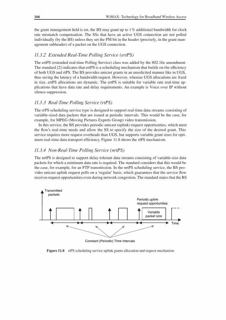
8/10/2019 WiMax-Tech for BBW Access
http://slidepdf.com/reader/full/wimax-tech-for-bbw-access 183/293
166 WiMAX: Technology for Broadband Wireless Access
the grant management field is set, the BS may grant up to 1 % additional bandwidth for clock
rate mismatch compensation. The SSs that have an active UGS connection are not polled
individually (by the BS) unless they set the PM bit in the header (precisely, in the grant man-
agement subheader) of a packet on the UGS connection.
11.3.2 Extended Real-Time Polling Service (ertPS)
The ertPS (extended real-time Polling Service) class was added by the 802.16e amendment.
The standard [2] indicates that ertPS is a scheduling mechanism that builds on the ef ficiency
of both UGS and rtPS. The BS provides unicast grants in an unsolicited manner like in UGS,
thus saving the latency of a bandwidth request. However, whereas UGS allocations are fixed
in size, ertPS allocations are dynamic. The ertPS is suitable for variable rate real-time ap-
plications that have data rate and delay requirements. An example is Voice over IP without
silence suppression.
11.3.3 Real-Time Polling Service (rtPS)
The rtPS scheduling service type is designed to support real-time data streams consisting of
variable-sized data packets that are issued at periodic intervals. This would be the case, for
example, for MPEG (Moving Pictures Experts Group) video transmission.
In this service, the BS provides periodic unicast (uplink) request opportunities, which meet
the flow’s real-time needs and allow the SS to specify the size of the desired grant. This
service requires more request overheads than UGS, but supports variable grant sizes for opti-
mum real-time data transport ef ficiency. Figure 11.8 shows the rtPS mechanism.
11.3.4 Non-Real-Time Polling Service (nrtPS)
The nrtPS is designed to support delay-tolerant data streams consisting of variable-size data
packets for which a minimum data rate is required. The standard considers that this would be
the case, for example, for an FTP transmission. In the nrtPS scheduling service, the BS pro-
vides unicast uplink request polls on a ‘regular’ basis, which guarantees that the service flow
receives request opportunities even during network congestion. The standard states that the BS
Constant (Periodic) Time Intervals
Variablepacket size
Transmitted
packets
Time
Periodic uplinkrequest opportunities
Figure 11.8 rtPS scheduling service uplink grants allocation and request mechanism

8/10/2019 WiMax-Tech for BBW Access
http://slidepdf.com/reader/full/wimax-tech-for-bbw-access 184/293
Network Entry and Quality of Service (QoS) Management 167
typically polls nrtPS CIDs on an interval on the order of one second or less. In addition, the SS
is allowed to use contention request opportunities, i.e. the SS may use contention request op-
portunities as well as unicast request opportunities. Figure 11.9 shows the nrtPS mechanism.
11.3.5 Best Effort (BE)
The BE service is designed to support data streams for which no minimum service guarantees
are required and therefore may be handled on a best available basis. The SS may use conten-
tion request opportunities as well as unicast request opportunities when the BS sends any.
The BS do not have any unicast uplink request polling obligation for BE SSs. Therefore, a
long period can run without transmitting any BE packets, typically when the network is in thecongestion state. Figure 11.10 shows the BE mechanism.
11.4 Scheduling and Deployment of Services Over WiMAX
11.4.1 The Scheduler is in the BS!
As already mentioned in this book, two topologies are defined: Point to MultiPoint (PMP)
and Mesh. In the PMP mode, the network operates with a central BS and probably with a
Time
Regular (not necessarily periodic) time intervals
Unicast polling
Variable
packetsize
Contention-based
uplink polling
Figure 11.9 Illustration of the nrtPS scheduling service uplink grants allocation and request mecha-
nism. The SS may use contention request opportunities as well as unicast request opportunities
Time
Completely nondeterministic time intervals
Unicast polling
Variablepacket size
Contention-based
uplink polling
Figure 11.10 Illustration of the BE scheduling service uplink grants allocation and request mecha-
nism. The BS does not have any unicast uplink request polling obligation for a BE SS
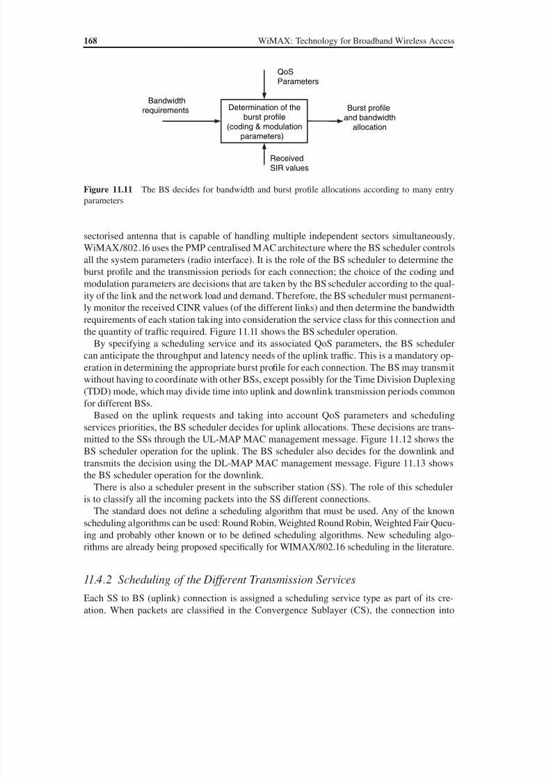
8/10/2019 WiMax-Tech for BBW Access
http://slidepdf.com/reader/full/wimax-tech-for-bbw-access 185/293
168 WiMAX: Technology for Broadband Wireless Access
sectorised antenna that is capable of handling multiple independent sectors simultaneously.WiMAX/802.16 uses the PMP centralised MAC architecture where the BS scheduler controls
all the system parameters (radio interface). It is the role of the BS scheduler to determine the
burst profile and the transmission periods for each connection; the choice of the coding and
modulation parameters are decisions that are taken by the BS scheduler according to the qual-
ity of the link and the network load and demand. Therefore, the BS scheduler must permanent-
ly monitor the received CINR values (of the different links) and then determine the bandwidth
requirements of each station taking into consideration the service class for this connection and
the quantity of traf fic required. Figure 11.11 shows the BS scheduler operation.
By specifying a scheduling service and its associated QoS parameters, the BS scheduler
can anticipate the throughput and latency needs of the uplink traf fic. This is a mandatory op-eration in determining the appropriate burst profile for each connection. The BS may transmit
without having to coordinate with other BSs, except possibly for the Time Division Duplexing
(TDD) mode, which may divide time into uplink and downlink transmission periods common
for different BSs.
Based on the uplink requests and taking into account QoS parameters and scheduling
services priorities, the BS scheduler decides for uplink allocations. These decisions are trans-
mitted to the SSs through the UL-MAP MAC management message. Figure 11.12 shows the
BS scheduler operation for the uplink. The BS scheduler also decides for the downlink and
transmits the decision using the DL-MAP MAC management message. Figure 11.13 shows
the BS scheduler operation for the downlink.There is also a scheduler present in the subscriber station (SS). The role of this scheduler
is to classify all the incoming packets into the SS different connections.
The standard does not define a scheduling algorithm that must be used. Any of the known
scheduling algorithms can be used: Round Robin, Weighted Round Robin, Weighted Fair Queu-
ing and probably other known or to be defined scheduling algorithms. New scheduling algo-
rithms are already being proposed specifically for WIMAX/802.16 scheduling in the literature.
11.4.2 Scheduling of the Different Transmission Services
Each SS to BS (uplink) connection is assigned a scheduling service type as part of its cre-
ation. When packets are classified in the Convergence Sublayer (CS), the connection into
Determination of the
burst profile(coding & modulation
parameters)
ReceivedSIR values
Bandwidthrequirements
QoSParameters
Burst profile
and bandwidthallocation
Figure 11.11 The BS decides for bandwidth and burst profile allocations according to many entry
parameters

8/10/2019 WiMax-Tech for BBW Access
http://slidepdf.com/reader/full/wimax-tech-for-bbw-access 186/293
Network Entry and Quality of Service (QoS) Management 169
which they are placed is chosen based on the type of QoS guarantees that are required by the
application (see Figures 11.12 and 11.13).
Although the standard gives all the details about the different classes of QoS and the
methods of bandwidth allocation, the details of scheduling and reservation management are
left unstandardised and are then left for vendors and operators. In Table 11.5 the scheduling
MAC CS MAC CPS
PacketClassifier
UGS
rtPS
nrtPS
BE
MAC CSMAC CPS
Packet Re-construct
UGS
rtPS
nrtPS
BE
Scheduler
UL–MAP
TFTP
HTTP
VoIP, Video
HTTP
SS BS
TFTP
TDM Voice
(T1/E1)
TDM Voice
(T1/E1)
VoIP, Video
Figure 11.12 BS scheduler operation for the uplink [5]
VoIP, Video
TDM Voice(T1/E1)
MAC CS MAC CPS
UGS
rtPS
nrtPS
BE
MAC CSMAC CPS
UGS
rtPS
nrtPS
BE
Sche-duler
DL_MAP
TFTP
HTTP
HTTP
SS BS
TFTP
PacketClassifier
DataTraffic
VoIP, Video
TDM Voice(T1/E1)
Figure 11.13 BS scheduler operation for the downlink [5]
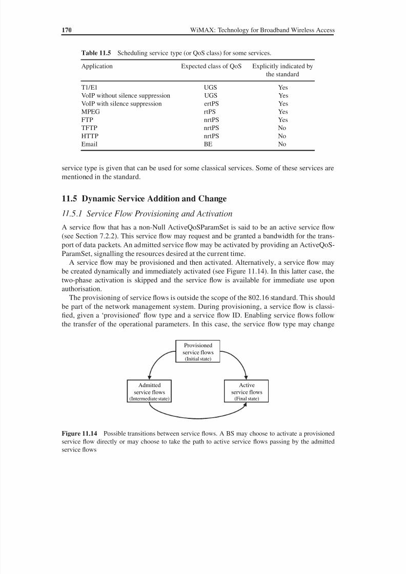
8/10/2019 WiMax-Tech for BBW Access
http://slidepdf.com/reader/full/wimax-tech-for-bbw-access 187/293
170 WiMAX: Technology for Broadband Wireless Access
service type is given that can be used for some classical services. Some of these services are
mentioned in the standard.
11.5 Dynamic Service Addition and Change
11.5.1 Service Flow Provisioning and Activation
A service flow that has a non-Null ActiveQoSParamSet is said to be an active service flow
(see Section 7.2.2). This service flow may request and be granted a bandwidth for the trans-
port of data packets. An admitted service flow may be activated by providing an ActiveQoS-
ParamSet, signalling the resources desired at the current time.
A service flow may be provisioned and then activated. Alternatively, a service flow maybe created dynamically and immediately activated (see Figure 11.14). In this latter case, the
two-phase activation is skipped and the service flow is available for immediate use upon
authorisation.
The provisioning of service flows is outside the scope of the 802.16 standard. This should
be part of the network management system. During provisioning, a service flow is classi-
fied, given a ‘provisioned’ flow type and a service flow ID. Enabling service flows follow
the transfer of the operational parameters. In this case, the service flow type may change
Table 11.5 Scheduling service type (or QoS class) for some services.
Application Expected class of QoS Explicitly indicated by
the standard
T1/E1 UGS YesVoIP without silence suppression UGS Yes
VoIP with silence suppression ertPS Yes
MPEG rtPS Yes
FTP nrtPS Yes
TFTP nrtPS No
HTTP nrtPS No
Email BE No
Provisioned
service flows(Initial state)
Active
service flows(Final state)
Admitted
service flows(Intermediate state)
Figure 11.14 Possible transitions between service flows. A BS may choose to activate a provisionedservice flow directly or may choose to take the path to active service flows passing by the admitted
service flows
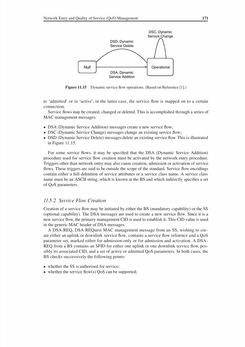
8/10/2019 WiMax-Tech for BBW Access
http://slidepdf.com/reader/full/wimax-tech-for-bbw-access 188/293

8/10/2019 WiMax-Tech for BBW Access
http://slidepdf.com/reader/full/wimax-tech-for-bbw-access 189/293
172 WiMAX: Technology for Broadband Wireless Access
and then possibly creates SFID and, if AdmittedQoSParamSet is non-null, maps the ser-vice flow to a CID. The BS or the SS responds with the DSA-RSP, DSA Response, MAC
management message, indicating acceptance or rejection. Figure 11.16 shows the service
flow creation procedure messages.
For DSA-REQ and DSC-REQ messages sent by an SS, the DSX-RVD (DSx Received)
message is generated by the BS to inform the SS that the BS has correctly received the DSx-
REQ message. This can be done quickly before sending the DSx-RSP message, which is
transmitted only after the DSx-REQ is authenticated.
The general format of DSA-REQ, DSA-RSP and DSA-ACK messages is shown in Figure
11.17. The DSA-REQ message cannot contain parameters for more than one service flow. The
transaction ID is a unique identifier for this transaction assigned by the sender. The confirma-tion code indicates the status for the dynamic service (DSx-xxx) messages. Possible values
are: OK-success, reject, reject-service-flow-exists, reject-header-suppression, reject-authenti-
cation-failure, etc.
DSA-REQ
(Service Flow)
DSA-RSP (SFID, CID,
Traffic priority, service class
name …)
DSA-ACK (Confirmation)
(SFID, CID, Max rate…)
Requestor
MAC
Responder
MAC
Responder
CS
MAC create
connection request
MAC create
connection indication
MAC create
connection response
MAC create
connection
confirmation
(CID, service class name, Traffic
priority, Max rate, QoS parameter
set type …)
Requestor
CS
Figure 11.16 Successful service flow creation procedure messages and attributes. Some of the param-
eters in this figure are not included in some DSx messages depending on whether the service creation is
BS or SS initiated. (Figure from Reference [1] modified by G. Assaf.)
TLV encodedinformation
Transaction IDConfirmation
code (only DSARSP and ACK)
Managementmessage type (=11,
12 or 13)
Figure 11.17 The general format of DSA-REQ, DSA-RSP and DSA-ACK MAC management
messages
8/10/2019 WiMax-Tech for BBW Access
http://slidepdf.com/reader/full/wimax-tech-for-bbw-access 190/293
Network Entry and Quality of Service (QoS) Management 173
The TLV encoded information field contains the specification of the service flow’s traf fic
characteristics, CS specific parameters and scheduling requirements. These parameters are:
• CID: specifies the CID assigned by the BS to a service flow. The CID is used in bandwidth
requests and in MAC PDU headers.• SFID: the primary reference of a service flow. Only the BS may issue an SFID in BS-
initiated DSA-REQ/DSC-REQ messages and in its DSA-RSP/DSC-RSP to SS-initiated
DSA-REQ/DSC-REQ messages. The SS specifies the SFID of a service flow using this
parameter in a DSC-REQ message.
• Service class name: see Section 11.5.1 above.
• QoS parameter set type: provisioned, admitted or active.
• Traf fic priority. The value of this parameter specifies the priority assigned to a service flow.
Given two service flows identical in all QoS parameters besides priority, the higher priority
service flow should be given lower delay and higher buffering preference. For nonidentical
service flows, the priority parameter should not take precedence over any conflicting ser-vice flow QoS parameter. No specific algorithm for using this parameter is given in the stan-
dard. For uplink service flows, the BS uses this parameter when determining precedence in
request service and grant generation.
• Scheduling service type. This is the one that should be enabled for the associated service
flow, between the five defined scheduling service types: BE (default), nrtPS, rtPS, ertPS or
UGS. If this parameter is omitted, BE service is assumed. An undefined scheduling service
type (implementation-dependent) can also be set.
• Other QoS parameters: maximum sustained traf fic rate, maximum traf fic burst, minimum
reserved traf fic rate, minimum tolerable traf fic rate, ARQ parameters for ARQ-enabled con-
nections, etc. (see QoS parameters in Section 7.4).• Target SAID (Security Association IDentifier). This indicates the SAID on to which the ser-
vice flow that is being set up will be mapped. The SAID is a security association identi fier
shared between the BS and the SS (see Chapter 15).
• CS specification. This specifies the CS that the connection being set up will use. Possi-
ble choices are No CS, Packet IPv4, Packet IPv6, Packet 802.3/Ethernet, Packet 802.1Q
VLAN, Packet IPv4 over 802.3/Ethernet, Packet IPv6 over 802.3/Ethernet, Packet IPv4
over 802.1Q VLAN, Packet IPv6 over 802.1Q VLAN and ATM.
11.5.3 Service Flow Modification and DeletionBoth provisioned and dynamically created service flows are modified with the DSC message,
which can change the admitted and active QoS parameter sets of the flow. A single DSC
message exchange can modify the parameters of either one downlink service flow or one
uplink service flow.
A successful DSC transaction changes the service flow QoS parameters by replacing both
the admitted and active QoS parameter sets. If the message contains only the admitted set, the
active set is set to null and the flow is deactivated. If the message contains neither set, then both
sets are set to null and the flow is de-admitted. When the message contains both QoS param-
eter sets, the admitted set is checked first and, if the admission control succeeds, the active set
in the message is checked against the admitted set in the message to ensure that it is a subset. If
all checks are successful, the QoS parameter sets in the message become the new admitted and

8/10/2019 WiMax-Tech for BBW Access
http://slidepdf.com/reader/full/wimax-tech-for-bbw-access 191/293
174 WiMAX: Technology for Broadband Wireless Access
active QoS parameter sets for the service flow. If either of the checks fails, the DSC transaction
fails and the service flow QoS parameter sets are unchanged. Some service flow parameters,
including the service flow scheduling type, may not be changed with the DSC messages.
An SS wishing to delete a service flow generates the DSD-REQuest message to the BS.
The BS verifies that the SS is really the service flow ‘owner’ and then removes the serviceflow. The BS responds using the DSD-RSP message. On the other hand, a BS wishing to
delete a dynamic service flow, no longer needed, generates a delete request to the associated
SS using a DSD-REQuest. The SS removes the service flow and generates a response using
a DSD-RSP.
11.5.4 Authorisation Module
The authorisation module is a logical function within the BS that approves or denies every
change to QoS parameters and classifiers associated with a service flow. This includes every
DSA-REQ message aiming to create a new service flow and every DSC-REQ message aim-
ing to change a QoS parameter set of an existing service flow. Such changes include request-
ing an admission control decision (e.g. setting the AdmittedQoSParamSet) and requesting
activation of a service flow (e.g. setting the ActiveQoSParamSet).
In the static authorisation model, the authorisation module stores the provisioned status of
all deferred service flows. Admission and activation requests for these provisioned service
flows are permitted as long as the admitted QoS parameter set is a subset of the provisioned
QoS parameter set and the active QoS parameter set is a subset of the admitted QoS pa-
rameter set. Requests to change the provisioned QoS parameter set are refused. Requests to
create new dynamic service flows are refused. This defines a static system where all possibleservices are defined in the initial configuration of each SS.
In the dynamic authorisation model, the authorisation module communicates through a
separate interface to an independent policy server. This policy server may provide the au-
thorisation module with advance notice of upcoming admission and activation requests, and
it specifies the proper authorisation action to be taken on those requests. Admission and
activation requests from an SS are then checked by the authorisation module to ensure that
the ActiveQoSParamSet being requested is a subset of the set provided by the policy server.
Admission and activation requests from an SS that are signalled in advance by the external
policy server are permitted. Admission and activation requests from an SS that are not pres-
ignalled by the external policy server may result in a real-time query to the policy server ormay be refused.
Prior to the initial connection setup, the BS retrieves the provisioned QoS set for an SS.
This is handed to the authorisation module within the BS. The BS caches the provisioned
QoS parameter set and uses this information to authorise dynamic flows that are a subset of
the provisioned QoS parameter set. The standard states that the BS should implement mecha-
nisms for overriding this automated approval process (such as described in the dynamic au-
thorisation model). For example it could:
(a) deny all requests whether or not they have been pre-provisioned;
(b) define an internal table with a richer policy mechanism but seeded by the provisioned
QoS set;
(c) refer all requests to an external policy server.
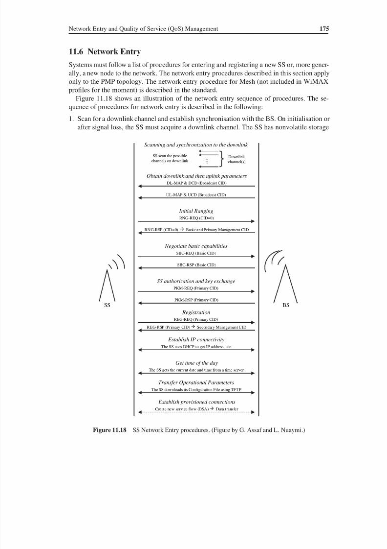
8/10/2019 WiMax-Tech for BBW Access
http://slidepdf.com/reader/full/wimax-tech-for-bbw-access 192/293
Network Entry and Quality of Service (QoS) Management 175
11.6 Network Entry
Systems must follow a list of procedures for entering and registering a new SS or, more gener-
ally, a new node to the network. The network entry procedures described in this section apply
only to the PMP topology. The network entry procedure for Mesh (not included in WiMAXprofiles for the moment) is described in the standard.
Figure 11.18 shows an illustration of the network entry sequence of procedures. The se-
quence of procedures for network entry is described in the following:
1. Scan for a downlink channel and establish synchronisation with the BS. On initialisation or
after signal loss, the SS must acquire a downlink channel. The SS has nonvolatile storage
SS
Scanning and synchronization to the downlink
…SS scan the possible
channels on downlink Downlink
channel(s)
Obtain downlink and then uplink parameters
DL-MAP & DCD (Broadcast CID)
UL-MAP & UCD (Broadcast CID)
Initial Ranging
RNG-REQ (CID=0)
RNG-RSP (CID=0) Basic and Primary Management CID
Negotiate basic capabilities
SBC-REQ (Basic CID)
SBC-RSP (Basic CID)
SS authorization and key exchange
PKM-REQ (Primary CID)
PKM-RSP (Primary CID)
Registration
REG-REQ (Primary CID)
REG-RSP (Primary CID) Secondary Management CID
Establish IP connectivity
The SS uses DHCP to get IP address, etc.
Establish provisioned connections
Create new service flow (DSA) Data transfer
BS
Get time of the day
The SS gets the current date and time from a time server
Transfer Operational Parameters
The SS downloads its Configuration File using TFTP
Figure 11.18 SS Network Entry procedures. (Figure by G. Assaf and L. Nuaymi.)
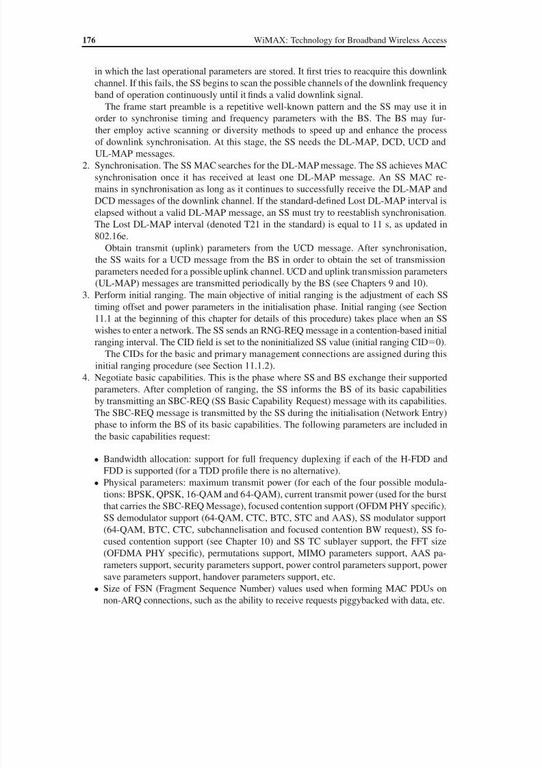
8/10/2019 WiMax-Tech for BBW Access
http://slidepdf.com/reader/full/wimax-tech-for-bbw-access 193/293
176 WiMAX: Technology for Broadband Wireless Access
in which the last operational parameters are stored. It first tries to reacquire this downlink
channel. If this fails, the SS begins to scan the possible channels of the downlink frequency
band of operation continuously until it finds a valid downlink signal.
The frame start preamble is a repetitive well-known pattern and the SS may use it in
order to synchronise timing and frequency parameters with the BS. The BS may fur-ther employ active scanning or diversity methods to speed up and enhance the process
of downlink synchronisation. At this stage, the SS needs the DL-MAP, DCD, UCD and
UL-MAP messages.
2. Synchronisation. The SS MAC searches for the DL-MAP message. The SS achieves MAC
synchronisation once it has received at least one DL-MAP message. An SS MAC re-
mains in synchronisation as long as it continues to successfully receive the DL-MAP and
DCD messages of the downlink channel. If the standard-defined Lost DL-MAP interval is
elapsed without a valid DL-MAP message, an SS must try to reestablish synchronisation.
The Lost DL-MAP interval (denoted T21 in the standard) is equal to 11 s, as updated in
802.16e.Obtain transmit (uplink) parameters from the UCD message. After synchronisation,
the SS waits for a UCD message from the BS in order to obtain the set of transmission
parameters needed for a possible uplink channel. UCD and uplink transmission parameters
(UL-MAP) messages are transmitted periodically by the BS (see Chapters 9 and 10).
3. Perform initial ranging. The main objective of initial ranging is the adjustment of each SS
timing offset and power parameters in the initialisation phase. Initial ranging (see Section
11.1 at the beginning of this chapter for details of this procedure) takes place when an SS
wishes to enter a network. The SS sends an RNG-REQ message in a contention-based initial
ranging interval. The CID field is set to the noninitialized SS value (initial ranging CID0).
The CIDs for the basic and primary management connections are assigned during this
initial ranging procedure (see Section 11.1.2).
4. Negotiate basic capabilities. This is the phase where SS and BS exchange their supported
parameters. After completion of ranging, the SS informs the BS of its basic capabilities
by transmitting an SBC-REQ (SS Basic Capability Request) message with its capabilities.
The SBC-REQ message is transmitted by the SS during the initialisation (Network Entry)
phase to inform the BS of its basic capabilities. The following parameters are included in
the basic capabilities request:
• Bandwidth allocation: support for full frequency duplexing if each of the H-FDD and
FDD is supported (for a TDD profile there is no alternative).
• Physical parameters: maximum transmit power (for each of the four possible modula-
tions: BPSK, QPSK, 16-QAM and 64-QAM), current transmit power (used for the burst
that carries the SBC-REQ Message), focused contention support (OFDM PHY specific),
SS demodulator support (64-QAM, CTC, BTC, STC and AAS), SS modulator support
(64-QAM, BTC, CTC, subchannelisation and focused contention BW request), SS fo-
cused contention support (see Chapter 10) and SS TC sublayer support, the FFT size
(OFDMA PHY specific), permutations support, MIMO parameters support, AAS pa-
rameters support, security parameters support, power control parameters support, power
save parameters support, handover parameters support, etc.
• Size of FSN (Fragment Sequence Number) values used when forming MAC PDUs on
non-ARQ connections, such as the ability to receive requests piggybacked with data, etc.
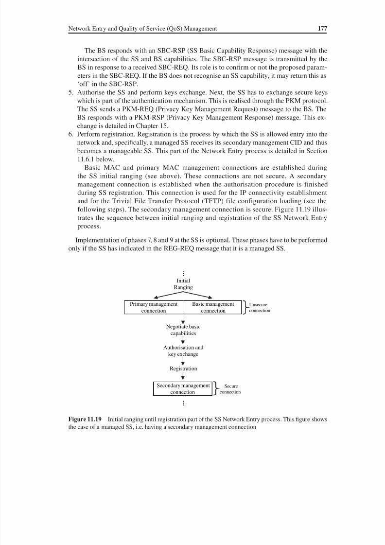
8/10/2019 WiMax-Tech for BBW Access
http://slidepdf.com/reader/full/wimax-tech-for-bbw-access 194/293
Network Entry and Quality of Service (QoS) Management 177
The BS responds with an SBC-RSP (SS Basic Capability Response) message with the
intersection of the SS and BS capabilities. The SBC-RSP message is transmitted by the
BS in response to a received SBC-REQ. Its role is to confirm or not the proposed param-
eters in the SBC-REQ. If the BS does not recognise an SS capability, it may return this as
‘off ’ in the SBC-RSP.5. Authorise the SS and perform keys exchange. Next, the SS has to exchange secure keys
which is part of the authentication mechanism. This is realised through the PKM protocol.
The SS sends a PKM-REQ (Privacy Key Management Request) message to the BS. The
BS responds with a PKM-RSP (Privacy Key Management Response) message. This ex-
change is detailed in Chapter 15.
6. Perform registration. Registration is the process by which the SS is allowed entry into the
network and, specifically, a managed SS receives its secondary management CID and thus
becomes a manageable SS. This part of the Network Entry process is detailed in Section
11.6.1 below.
Basic MAC and primary MAC management connections are established duringthe SS initial ranging (see above). These connections are not secure. A secondary
management connection is established when the authorisation procedure is finished
during SS registration. This connection is used for the IP connectivity establishment
and for the Trivial File Transfer Protocol (TFTP) file configuration loading (see the
following steps). The secondary management connection is secure. Figure 11.19 illus-
trates the sequence between initial ranging and registration of the SS Network Entry
process.
Implementation of phases 7, 8 and 9 at the SS is optional. These phases have to be performed
only if the SS has indicated in the REG-REQ message that it is a managed SS.
Initial
Ranging
Registration
Primary management
connection
Negotiate basic
capabilities
Authorisation and
key exchange
Basic management
connection
Secondary management
connection
…
…
Secure
connection
Unsecure
connection
Figure 11.19 Initial ranging until registration part of the SS Network Entry process. This figure shows
the case of a managed SS, i.e. having a secondary management connection
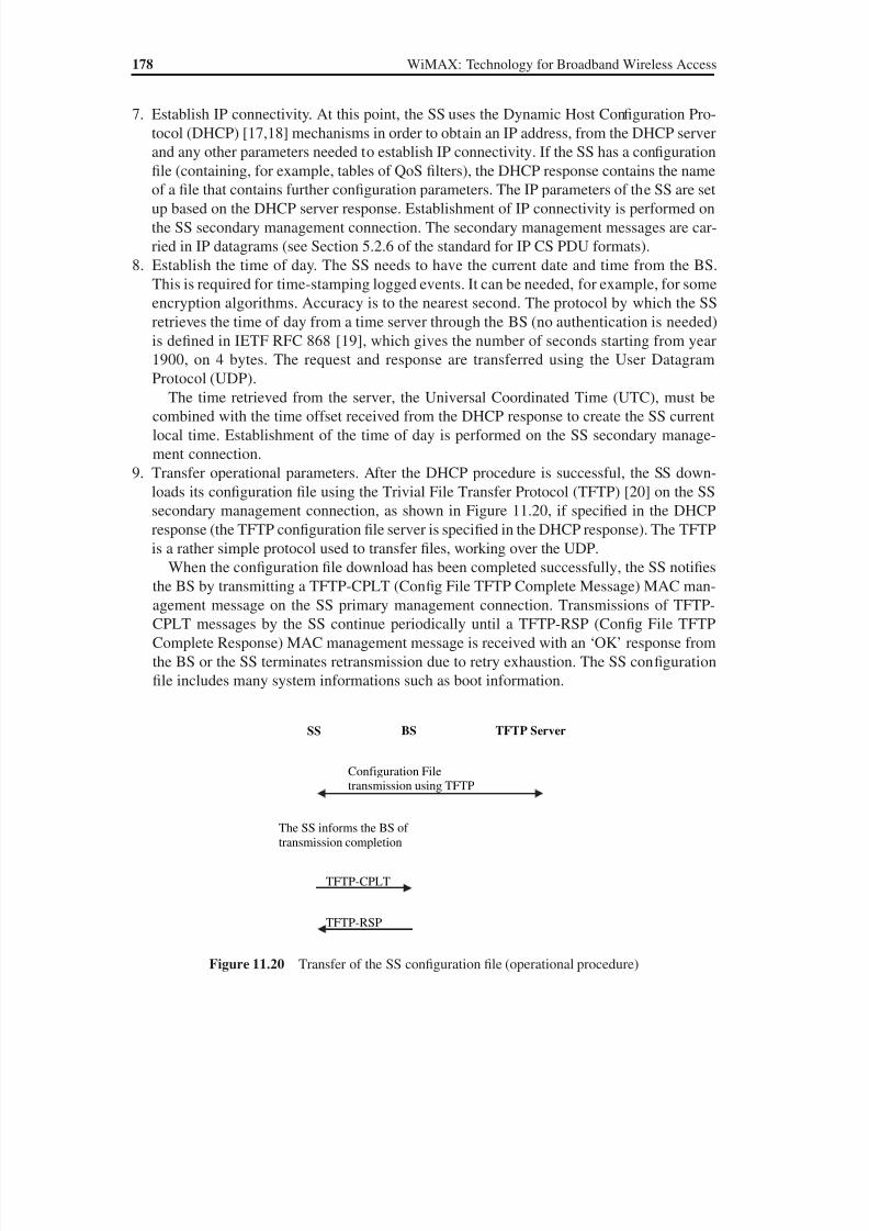
8/10/2019 WiMax-Tech for BBW Access
http://slidepdf.com/reader/full/wimax-tech-for-bbw-access 195/293
8/10/2019 WiMax-Tech for BBW Access
http://slidepdf.com/reader/full/wimax-tech-for-bbw-access 196/293
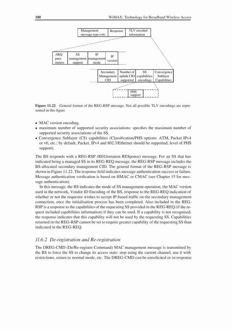
8/10/2019 WiMax-Tech for BBW Access
http://slidepdf.com/reader/full/wimax-tech-for-bbw-access 197/293
180 WiMAX: Technology for Broadband Wireless Access
• MAC version encoding.
• maximum number of supported security associations: specifies the maximum number of
supported security associations of the SS.
• Convergence Sublayer (CS) capabilities (Classification/PHS options: ATM, Packet IPv4
or v6, etc.; by default, Packet, IPv4 and 802.3/Ethernet should be supported, level of PHS
support).
The BS responds with a REG-RSP (REGistration RESponse) message. For an SS that has
indicated being a managed SS in its REG-REQ message, the REG-RSP message includes the
BS-allocated secondary management CID. The general format of the REG-RSP message is
shown in Figure 11.22. The response field indicates message authentication success or failure.
Message authentication verification is based on HMAC or CMAC (see Chapter 15 for mes-
sage authentication).
In this message, the BS indicates the mode of SS management operation, the MAC version
used in the network, Vendor ID Encoding of the BS, response to the REG-REQ indication of
whether or not the requester wishes to accept IP-based traf fic on the secondary management
connection, once the initialisation process has been completed. Also included in the REG-
RSP is a response to the capabilities of the requesting SS provided in the REG-REQ (if the re-
quest included capabilities information) if they can be used. If a capability is not recognised,
the response indicates that this capability will not be used by the requesting SS. Capabilities
returned in the REG-RSP cannot be set to require greater capability of the requesting SS than
indicated in the REG-REQ.
11.6.2 De-registration and Re-registration
The DREG-CMD (De/Re-register Command) MAC management message is transmitted by
the BS to force the SS to change its access state: stop using the current channel, use it with
restrictions, return to normal mode, etc. The DREG-CMD can be unsolicited or in response
TLV encoded
information
Management
message type (=6)
SS
management
support
IP
management
mode
Secondary
Management
CID
IP
version
Number of
uplink CID
supported
SS
capabilities
encodings
ARQ
para-
meters
Convergence
Sublayer
Capabilities
PHSsupport
Response
Figure 11.22 General format of the REG-RSP message. Not all possible TLV encodings are repre-
sented in this figure

8/10/2019 WiMax-Tech for BBW Access
http://slidepdf.com/reader/full/wimax-tech-for-bbw-access 198/293

8/10/2019 WiMax-Tech for BBW Access
http://slidepdf.com/reader/full/wimax-tech-for-bbw-access 199/293
Part FourDiverse Topics
WiMAX: Technology for Broadband Wireless Access Loutfi Nuaymi
© 2007 John Wiley & Sons, Ltd. ISBN: 0-470-02808-4

8/10/2019 WiMax-Tech for BBW Access
http://slidepdf.com/reader/full/wimax-tech-for-bbw-access 200/293
12Efficient Use of Radio ResourcesWith the contribution of Jérôme Brouet, Alcatel, France
12.1 Introduction
WiMAX systems are designed to provide high spectral efficiency in order to offer very highdata rates to users. The robust physical layer based on the OFDM/OFDMA technique andthe use of high-performance coding are partly responsible for the resulting high spectralefficiency (see Chapters 5 and 6).
On the one hand, spectral efficiency is enhanced by WiMAX Radio Resource Management(RRM) mechanisms (see Section 12.3). Those mechanisms, specified in the IEEE 802.16standards include admission control, power control, link adaptation and dynamic frequencyselection [1,2]. In addition to these radio mechanisms, the WiMAX Forum defines a frame-
work and a functional split of the radio resource management procedures in the WiMAXradio access network (WiMAX architecture is described in Chapter 13). This framework ac-tually further optimise RRM procedures (mainly for admission control and handover) and isespecially needed for consistent RRM operations in a multivendor WiMAX radio network.
On the other hand, high spectral efficiency and performance superiority over the other radiosystems is also achieved by the use of advanced antenna technology systems. The IEEE 802.16standards and associated WiMAX profiles are presently defining and taking provisions for sev-eral alternatives for implementing advanced antenna technologies (see Section 12.4). In thepresent version of a mobile WiMAX, both adaptive antenna technology with beamforming andMIMO technology are possible. While multiple antenna technologies had only been adopted
in enhanced releases for 3GPP and 3GPP2 standards, which makes their massive deploymentchallenging in an existing mature network, these technologies are actually supported from thevery first release of mobile WiMAX systems, making them a real feature for first WiMAX radionetwork deployments and consequently the key cornerstone for excellent radio performance.
Whereas previous techniques are clearly improving the performance of the systems forunicast connections between a BS and an MS (Mobile Station), the WiMAX Forum hasalso taken provision for an efficient support of Multicast/Broadcast Services (MBS) over theWiMAX air interface. In order to achieve high performance, WiMAX system deploymentshould follow some guidelines exposed hereafter.
WiMAX: Technology for Broadband Wireless Access Loutfi Nuaymi
© 2007 John Wiley & Sons, Ltd. ISBN: 0-470-02808-4

8/10/2019 WiMax-Tech for BBW Access
http://slidepdf.com/reader/full/wimax-tech-for-bbw-access 201/293
186 WiMAX: Technology for Broadband Wireless Access
12.2 Radio Engineering Consideration for WiMAX Systems
WiMAX solutions include fixed WiMAX and mobile WiMAX. According to the type of ter-minal offered (outdoor CPE (Consumer Premise Equipment), self-install indoor CPE, mobile
terminal–PCMCIA, laptop, smart phones), each solution has a different deployment method.
12.2.1 LOS/NLOS Propagation
Coverage from a BS is linked to several radio parameters. The first one is the propagationenvironment. Depending on the relative locations of the BS and the terminal, several modelscan be used to evaluate the losses due to propagation.
12.2.1.1 LOS and Near LOS Propagation
Line-of-Sight (LoS) and Near Line-of-Sight (NLoS) propagations may happen when the BSand the MS are deployed outdoor, above the average height of the environment. This may bethe case of the deployment of a fixed WiMAX solution in a rural environment with the BSlocated on a high altitude point (or at the top of a mast) and the SS (then a CPE, for a fixedWiMAX) deployed on the rooftop of the customer’s house.
LOS propagation requires that the first Fresnel zone is free from any obstacle. In that case,the propagation losses are proportional to the square of the distance between the BS and theSS [22]. However, in a practical deployment, this happens very seldom. Usually, the Fresnelzone is obstructed and/or there are few obstacles on the BS to the CPE transmission path. Inthat case, near LOS models are used. However, in the case where there are few obstacles (a
building, a water tower, a hill), the obstacles are modelled by knife-edge. An example of sucha model can be found in Reference [23].
12.2.1.2 NLOS Propagation
NLOS (Non-Line-of-Sight) propagation occurs when the terminal is located indoor and/or atground level. In this situation, there is in most cases no direct path between the BS and theterminal, there is a high number of obstacles on the BS to MS path (buildings, trees, cars, etc.)and the receiver may receive several copies of signal that experienced several reflections/dif-fractions on different obstacles. This type of propagation is typical of cellular deployments.
In the case of WiMAX, NLOS propagation corresponds to a deployment of a fixed ormobile WiMAX using self-install indoor terminals (wireless DSL deployment), or a deploy-ment of a mobile WiMAX with mobile terminals (PCMCIA, laptop with integrated chipset,multimode mobile phones, etc.).
In NLOS, the losses versus the distance are much higher that in LOS. Usually, the distancedecay exponent is between 3 and 4. An example of a propagation model that can be used toevaluate propagation losses in NLoS is the Erceg model [24].
12.2.2 Radio Parameters and System Gains
In order to evaluate the range, additional parameters are required. First, the value of somepropagation parameters depends on additional radio parameters such as:
8/10/2019 WiMax-Tech for BBW Access
http://slidepdf.com/reader/full/wimax-tech-for-bbw-access 202/293
8/10/2019 WiMax-Tech for BBW Access
http://slidepdf.com/reader/full/wimax-tech-for-bbw-access 203/293

8/10/2019 WiMax-Tech for BBW Access
http://slidepdf.com/reader/full/wimax-tech-for-bbw-access 204/293
Efficient Use of Radio Resources 189
among the BSs but each BS may use different permutations. Due to the time synchronisa-tion in this scenario and the long symbol duration of the OFDMA symbol, fast handoversas well as soft handovers are possible. This configuration can be used as an independent BSdeployment with a controlled interference level.
• Coordinated synchronous configuration. All the BSs work in the synchronous mode anduse the same permutations. An upper layer is responsible for the handling of subchannelallocations within the sectors of the base station, making sure that better handling of thebandwidth is achieved and enabling the system to handle and balance loads between thesectors and within the system.
The standard indicates that, for TDD and FDD realisations, it is recommended (but notrequired) that all BSs should be time-synchronised to a common timing signal.
12.3 Radio Resource Management Procedures
12.3.1 Power Control
The support of power control procedure is mandatory in the uplink. The procedure includesboth an initial calibration process and a periodic update process.
By measuring the received power at the BS side, the BS can send power offset indications to theMS, which adjusts its transmit power level accordingly. It has to be noted that in the case wherethe MS uses only a portion of the subchannels, the power density remains unchanged regardlessof the number of subchannels actually used (unless the maximum power level is reached).
The power offset indication sent by the BS is consistent with the actual MCS that is to beused for the uplink transmission. Power adjustments related to the use of a different modula-tion scheme is then taken into account. Finally, the power offset is also consistent with themaximum power that the MS can transmit (indicated in the SBC-REQ MAC message).
After reception of the power offset information, the MS adjusts its transmit power accord-ing to Equation (12.1) by simply adding the offset to the last value used for transmission:
PNew PLast Offset (12.1)
where Plast is the last used transmit power, Pnew the new transmit power and ‘Offset’ the ac-cumulation of offset values sent by the BS since the last transmission. Transmission poweroffset information is sent in RNG-RSP messages in units of 0.25 dB. This process allows for
power fluctuations at a rate of at most 30 dB/s with a depth of at least 10 dB.In the case of OFDMA-based WiMAX systems, the power control differs for some uplinkburst types. For uplink burst regions used for the fast feedback channel (UIUC 0), CDMAranging (UIUC 12) and CDMA allocation IE (UIUC 14), the transmit power updateformula of the MS is the following:
PNew PLast (C / N new C / N last) 10[log( Rnew) log( Rlast)] Offset (12.2)
where Pnew, Plast and ‘Offset’ are as defined in Equation (12.1), C / N new is the normalised C / N (Carrier over Noise) of the new MCS used in the region, C / N
last is the normalised C / N of the last used MCS,
Rnew is the number of repetitions of the new MCS used in the region, Rlast is the number of repetitions of the last MCS.
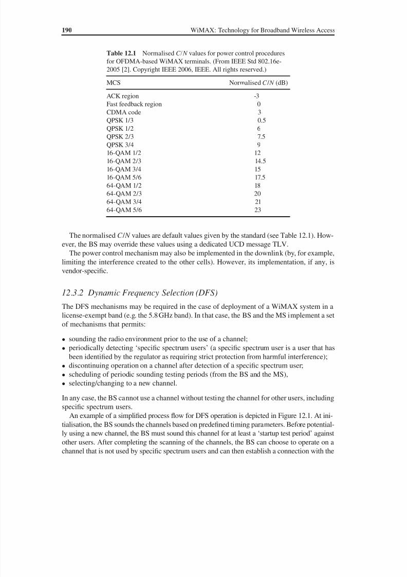
8/10/2019 WiMax-Tech for BBW Access
http://slidepdf.com/reader/full/wimax-tech-for-bbw-access 205/293
190 WiMAX: Technology for Broadband Wireless Access
The normalised C / N values are default values given by the standard (see Table 12.1). How-ever, the BS may override these values using a dedicated UCD message TLV.
The power control mechanism may also be implemented in the downlink (by, for example,
limiting the interference created to the other cells). However, its implementation, if any, isvendor-specific.
12.3.2 Dynamic Frequency Selection (DFS)
The DFS mechanisms may be required in the case of deployment of a WiMAX system in alicense-exempt band (e.g. the 5.8 GHz band). In that case, the BS and the MS implement a setof mechanisms that permits:
• sounding the radio environment prior to the use of a channel;
• periodically detecting ‘specific spectrum users’ (a specific spectrum user is a user that hasbeen identified by the regulator as requiring strict protection from harmful interference);
• discontinuing operation on a channel after detection of a specific spectrum user;
• scheduling of periodic sounding testing periods (from the BS and the MS),
• selecting/changing to a new channel.
In any case, the BS cannot use a channel without testing the channel for other users, includingspecific spectrum users.
An example of a simplified process flow for DFS operation is depicted in Figure 12.1. At ini-tialisation, the BS sounds the channels based on predefined timing parameters. Before potential-ly using a new channel, the BS must sound this channel for at least a ‘startup test period’ againstother users. After completing the scanning of the channels, the BS can choose to operate on achannel that is not used by specific spectrum users and can then establish a connection with the
Table 12.1 Normalised C/N values for power control proceduresfor OFDMA-based WiMAX terminals. (From IEEE Std 802.16e-2005 [2]. Copyright IEEE 2006, IEEE. All rights reserved.)
MCS Normalised C / N (dB)
ACK region -3Fast feedback region 0CDMA code 3QPSK 1/3 0.5QPSK 1/2 6QPSK 2/3 7.5QPSK 3/4 916-QAM 1/2 1216-QAM 2/3 14.516-QAM 3/4 15
16-QAM 5/6 17.564-QAM 1/2 1864-QAM 2/3 2064-QAM 3/4 2164-QAM 5/6 23
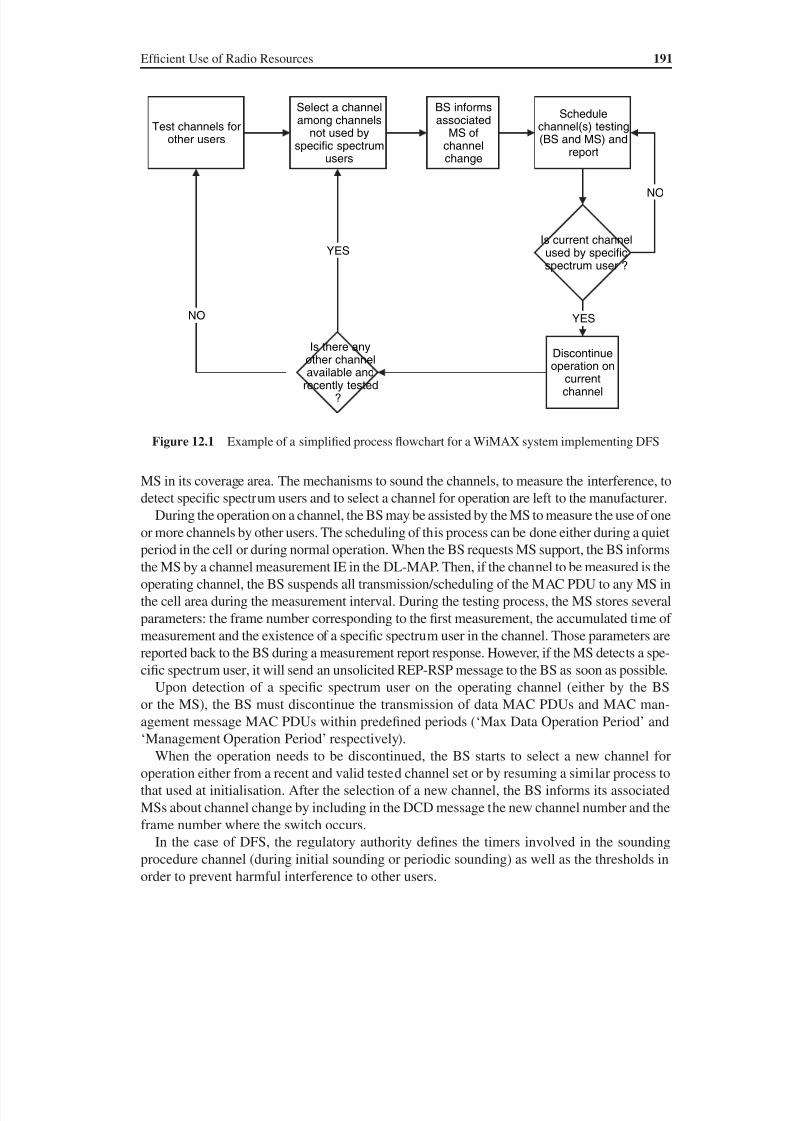
8/10/2019 WiMax-Tech for BBW Access
http://slidepdf.com/reader/full/wimax-tech-for-bbw-access 206/293
8/10/2019 WiMax-Tech for BBW Access
http://slidepdf.com/reader/full/wimax-tech-for-bbw-access 207/293
192 WiMAX: Technology for Broadband Wireless Access
Finally, a similar mechanism can be implemented for other purposes than DFS and may beapplied to any WiMAX deployments in shared channel environments.
12.3.3 Other Radio Resource Management ProceduresTo optimise the performance of IEEE 802.16-based systems, other radio resource managementprocedures are implemented. The admission control of new connections is part of the RRM op-eration. The WiMAX Forum defines a framework to support and optimise the admission con-trol (see Section 12.3.5). Admission control decision algorithms are left to the manufacturers.
Link adaptation mechanisms are also implemented. Again, the way the process operatesand the selection of the MCS according to channel conditions and other local criteria are leftto the vendor. More details on the supporting primitives for link adaptation are provided inChapter 11.
12.3.4 Channel Measurements
In order for the BS to take appropriate decisions for radio resource management (power con-trol, selection of the modulation and coding scheme and use of advanced antenna technol-ogy), the standard defines a set of channel quality indicators. Two families of indicators areavailable:
• RSSI (Received Signal Strength Indicator), which gives information on the received powerlevel;
• CINR (Carrier-to-Interference-and-Noise Ratio), which gives information on received car-
rier-to-interference levels.
WiMAX radio equipment (MS and BS) can implement the means to measure, compute andreport these indicators. In addition, to reflect the fluctuations of the radio channel in time, twostatistics of the indicators are evaluated and reported: the mean and standard deviation.
12.3.4.1 Received Signal Strength Indicator (RSSI)
RSSIs are derived from measured received power level samples. The reported RSSIs are anaverage (in linear scale, e.g. in mW) of the measured power level samples (averaging is done by
an exponential filter with a forgetting factor provided as a configuration parameter by the BS).The mean RSSI is obtained from
na n a
RSSIavg RSSI avg
if
if mW[ ]
[ ]
) [ ] [ ]( )
(k
R k
k R k k
0 0
1 1 0
(12.3)
where R[k ] is the measured power sample during message k and αavg is the averaging factor.The sample index k is incremented for every frame and the power is measured over the framepreamble. The averaging factor is transmitted by the BS either in a DCD message TLV or ina REP-REQ MAC message. Otherwise, the default value of 1/4 should be considered by theMS.

8/10/2019 WiMax-Tech for BBW Access
http://slidepdf.com/reader/full/wimax-tech-for-bbw-access 208/293
Efficient Use of Radio Resources 193
The standard deviation of RSSI is derived from the expectation-square statistics of themeasured signal levels, x 2RSSI, defined by
x k
R k
x k R k k RSSI
avg RSSI avg
if
if 2
2
2 2
0 0
1 1 0[ ]
| [ ] |
( ) [ ] | [ ] |
a a
( )mW2 (12.4)
The method to measure the received signal strength is vendor-specific. However, the measure-ments should remain inside a ±4 dB absolute error.
The reported values are sent in MAC REP-REQ message using the dBm (dB) scale for themean RSSI (respectively the standard deviation), as specified by
n n
v
RSSI dBm RSSI
RSSI dBm RSSI
dBm)[ ] log( [ ]) (
[ ] log(| [
k k
k x k
10
5 2 ]] ( [ ]) |) ( nRSSI
dB)k 2 (12.5)
The values are quantized with a 1 dB increment and each is sent in a 1-byte field in theMAC REP-REQ message. The range of RSSI spans from123 dBm to 40 dBm.
12.3.4.2 Carrier-to-Interference and Noise Ratio (CINR)
For the IEEE 802.16-2004-based systems (using OFDM), the reported CINR indicators arephysical CINR indicators. When the BS requests a CINR measurement report from the MS,the MS will answer back by including in the REP-RSP MAC message the estimates of the
average and standard deviations of the CINR. CINR values are reported in a dB scale with1 dB steps, ranging from 10 dB to 53 dB.
Reported CINR values are averaged using the same averaging method as that for the RSSI.The method to evaluate the CINR is vendor-specific. The measurement samples can be takeneither from detected or pilot samples.
For the IEEE 802.16-2005-based systems (using OFDMA), additional options are speci-fied. On the one hand, different CINR measurements are defined: physical and effectiveCINR measurements. On the other hand, the CINR reports may be sent either through theREP-REQ MAC message (mean and/or standard deviation of CINR) or through the fast-feedback channel (mean CINR only).
Several physical CINR reports can be requested from the MS:
• Physical CINR measurements on the preamble. In the case of frequency reuse 3 networks,the CINR is measured over modulated carriers of the preamble, while in the case of thefrequency reuse 1 network, the CINR are measured over all the subcarriers (modulated ornot, excluding the guard bands and DC channel).
• Physical CINR measurement from a permutation zone. In this case, CINR samples aremeasured from the pilots in the permutation zone.
In addition, the BS may also request ‘effective CINR’ measurements from a permutation zone onthe pilot subcarriers. The effective CINR is a function of the physical CINR, taking into accountchannel conditions and implementation margins (implementation is manufacturer-dependent).
8/10/2019 WiMax-Tech for BBW Access
http://slidepdf.com/reader/full/wimax-tech-for-bbw-access 209/293
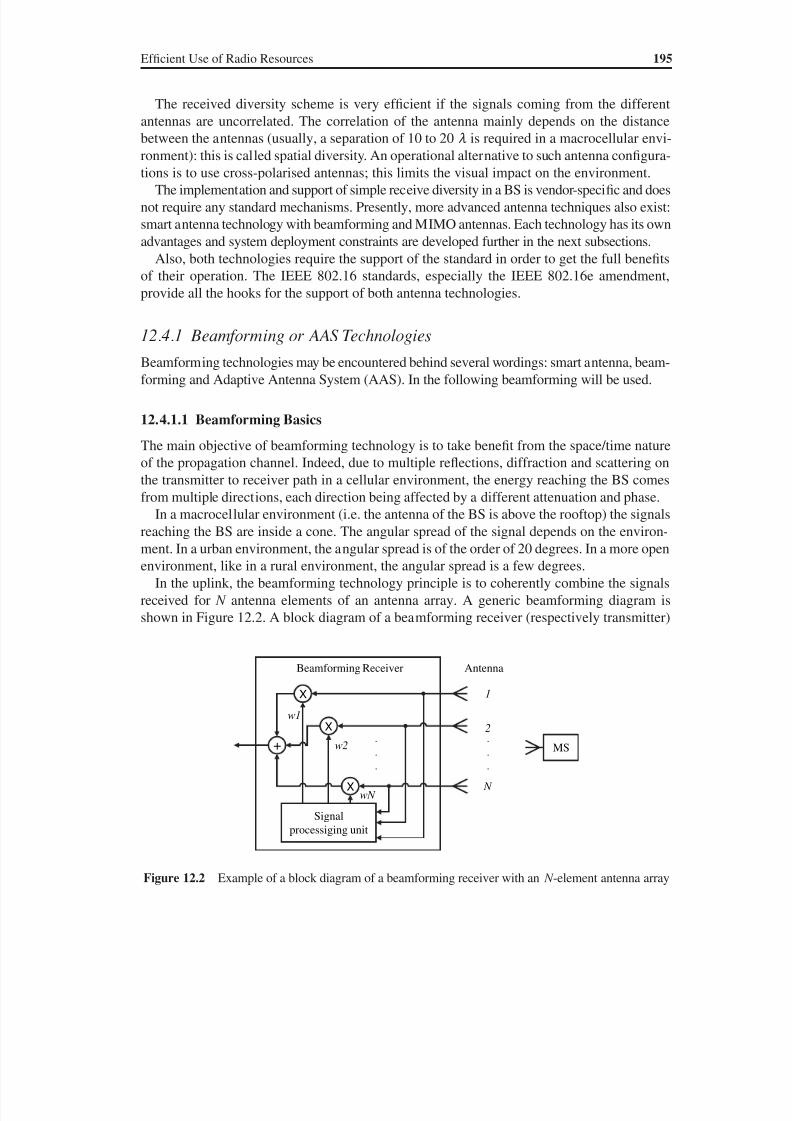
8/10/2019 WiMax-Tech for BBW Access
http://slidepdf.com/reader/full/wimax-tech-for-bbw-access 210/293
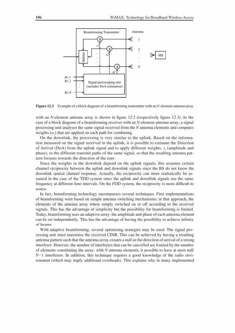
8/10/2019 WiMax-Tech for BBW Access
http://slidepdf.com/reader/full/wimax-tech-for-bbw-access 211/293
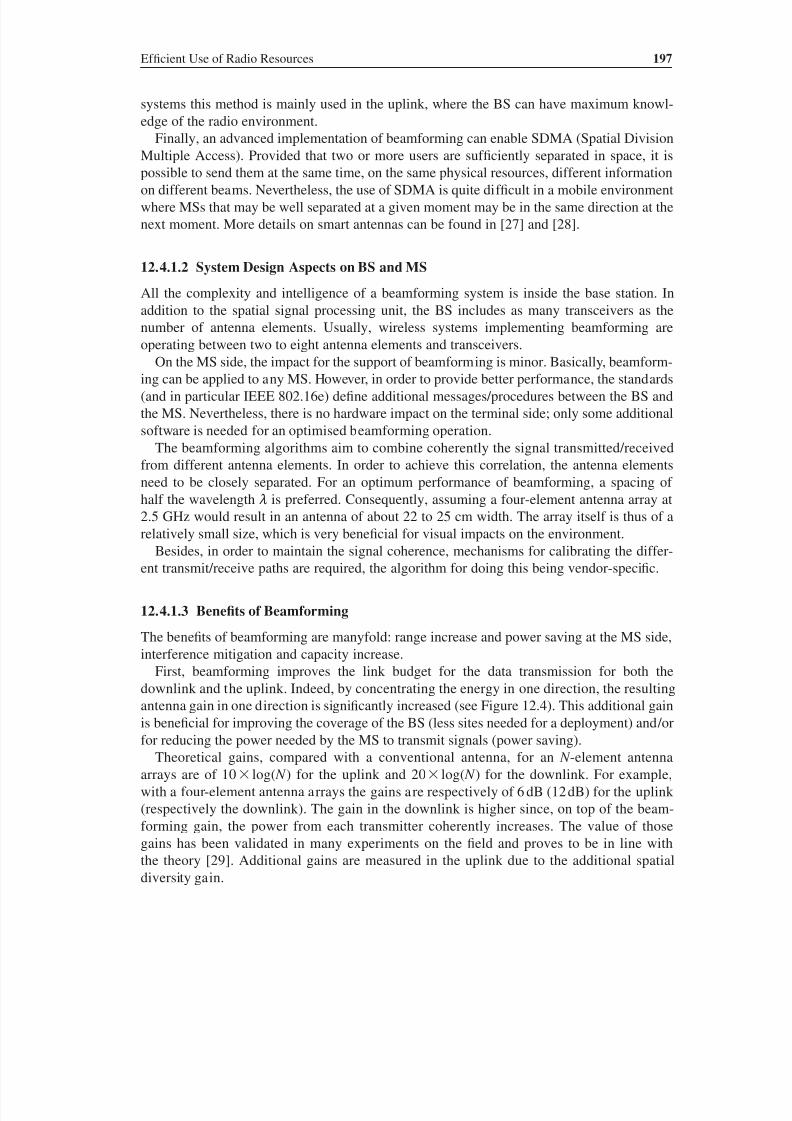
8/10/2019 WiMax-Tech for BBW Access
http://slidepdf.com/reader/full/wimax-tech-for-bbw-access 212/293
Ef ficient Use of Radio Resources 197
systems this method is mainly used in the uplink, where the BS can have maximum knowl-
edge of the radio environment.
Finally, an advanced implementation of beamforming can enable SDMA (Spatial Division
Multiple Access). Provided that two or more users are suf ficiently separated in space, it is
possible to send them at the same time, on the same physical resources, different informationon different beams. Nevertheless, the use of SDMA is quite dif ficult in a mobile environment
where MSs that may be well separated at a given moment may be in the same direction at the
next moment. More details on smart antennas can be found in [27] and [28].
12.4.1.2 System Design Aspects on BS and MS
All the complexity and intelligence of a beamforming system is inside the base station. In
addition to the spatial signal processing unit, the BS includes as many transceivers as the
number of antenna elements. Usually, wireless systems implementing beamforming are
operating between two to eight antenna elements and transceivers.On the MS side, the impact for the support of beamforming is minor. Basically, beamform-
ing can be applied to any MS. However, in order to provide better performance, the standards
(and in particular IEEE 802.16e) define additional messages/procedures between the BS and
the MS. Nevertheless, there is no hardware impact on the terminal side; only some additional
software is needed for an optimised beamforming operation.
The beamforming algorithms aim to combine coherently the signal transmitted/received
from different antenna elements. In order to achieve this correlation, the antenna elements
need to be closely separated. For an optimum performance of beamforming, a spacing of
half the wavelength m is preferred. Consequently, assuming a four-element antenna array at
2.5 GHz would result in an antenna of about 22 to 25 cm width. The array itself is thus of a
relatively small size, which is very beneficial for visual impacts on the environment.
Besides, in order to maintain the signal coherence, mechanisms for calibrating the differ-
ent transmit/receive paths are required, the algorithm for doing this being vendor-specific.
12.4.1.3 Benefits of Beamforming
The benefits of beamforming are manyfold: range increase and power saving at the MS side,
interference mitigation and capacity increase.
First, beamforming improves the link budget for the data transmission for both the
downlink and the uplink. Indeed, by concentrating the energy in one direction, the resulting
antenna gain in one direction is significantly increased (see Figure 12.4). This additional gain
is beneficial for improving the coverage of the BS (less sites needed for a deployment) and/or
for reducing the power needed by the MS to transmit signals (power saving).
Theoretical gains, compared with a conventional antenna, for an N -element antenna
arrays are of 10 log( N ) for the uplink and 20 log( N ) for the downlink. For example,
with a four-element antenna arrays the gains are respectively of 6 dB (12 dB) for the uplink
(respectively the downlink). The gain in the downlink is higher since, on top of the beam-
forming gain, the power from each transmitter coherently increases. The value of those
gains has been validated in many experiments on the field and proves to be in line with
the theory [29]. Additional gains are measured in the uplink due to the additional spatial
diversity gain.
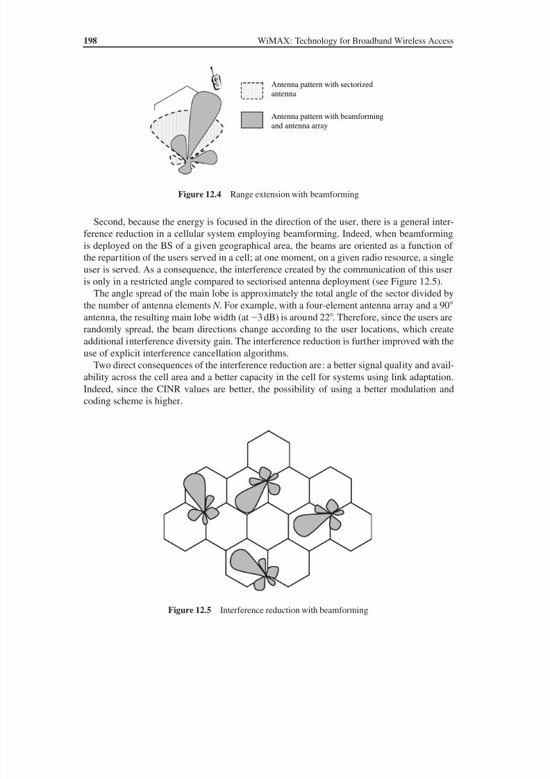
8/10/2019 WiMax-Tech for BBW Access
http://slidepdf.com/reader/full/wimax-tech-for-bbw-access 213/293
198 WiMAX: Technology for Broadband Wireless Access
Second, because the energy is focused in the direction of the user, there is a general inter-
ference reduction in a cellular system employing beamforming. Indeed, when beamformingis deployed on the BS of a given geographical area, the beams are oriented as a function of
the repartition of the users served in a cell; at one moment, on a given radio resource, a single
user is served. As a consequence, the interference created by the communication of this user
is only in a restricted angle compared to sectorised antenna deployment (see Figure 12.5).
The angle spread of the main lobe is approximately the total angle of the sector divided by
the number of antenna elements N . For example, with a four-element antenna array and a 90
antenna, the resulting main lobe width (at3 dB) is around 22. Therefore, since the users are
randomly spread, the beam directions change according to the user locations, which create
additional interference diversity gain. The interference reduction is further improved with the
use of explicit interference cancellation algorithms.Two direct consequences of the interference reduction are: a better signal quality and avail-
ability across the cell area and a better capacity in the cell for systems using link adaptation.
Indeed, since the CINR values are better, the possibility of using a better modulation and
coding scheme is higher.
Figure 12.5 Interference reduction with beamforming
Figure 12.4 Range extension with beamforming
Antenna pattern with sectorized
antenna
Antenna pattern with beamformingand antenna array
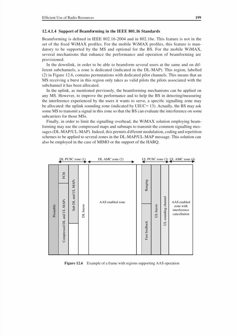
8/10/2019 WiMax-Tech for BBW Access
http://slidepdf.com/reader/full/wimax-tech-for-bbw-access 214/293
Ef ficient Use of Radio Resources 199
12.4.1.4 Support of Beamforming in the IEEE 801.16 Standards
Beamforming is defined in IEEE 802.16-2004 and in 802.16e. This feature is not in the
set of the fixed WiMAX profiles. For the mobile WiMAX profiles, this feature is man-
datory to be supported by the MS and optional for the BS. For the mobile WiMAX,several mechanisms that enhance the performance and operation of beamforming are
provisioned.
In the downlink, in order to be able to beamform several users at the same and on dif-
ferent subchannels, a zone is dedicated (indicated in the DL-MAP). This region, labelled
(2) in Figure 12.6, contains permutations with dedicated pilot channels. This means that an
MS receiving a burst in this region only takes as valid pilots the pilots associated with the
subchannel it has been allocated.
In the uplink, as mentioned previously, the beamforming mechanisms can be applied on
any MS. However, to improve the performance and to help the BS in detecting/measuring
the interference experienced by the users it wants to serve, a specific signalling zone maybe allocated: the uplink sounding zone (indicated by UIUC13). Actually, the BS may ask
some MS to transmit a signal in this zone so that the BS can evaluate the interference on some
subcarriers for those MSs.
Finally, in order to limit the signalling overhead, the WiMAX solution employing beam-
forming may use the compressed maps and submaps to transmit the common signalling mes-
sages (DL-MAP/UL-MAP). Indeed, this permits different modulation, coding and repetition
schemes to be applied to several zones in the DL-MAP/UL-MAP message. This solution can
also be employed in the case of MIMO or the support of the HARQ.
Figure 12.6 Example of a frame with regions supporting AAS operation
F C H
R a n g i n g
S u b D
L a n d U L M A P s
P r e a m b l e
C o m p r e s s e d D L a n d U L M A
P s
D L b u r s t s
AAS enabled zone
F a s t f e e d b a c k
U L b u r s t s
U L s o u n d i n g c h a n n e l
AAS enabled
zone with
interference
cancellation
UL AMC zone (4)DL PUSC zone (1) UL PUSC zone (3)DL AMC zone (2)
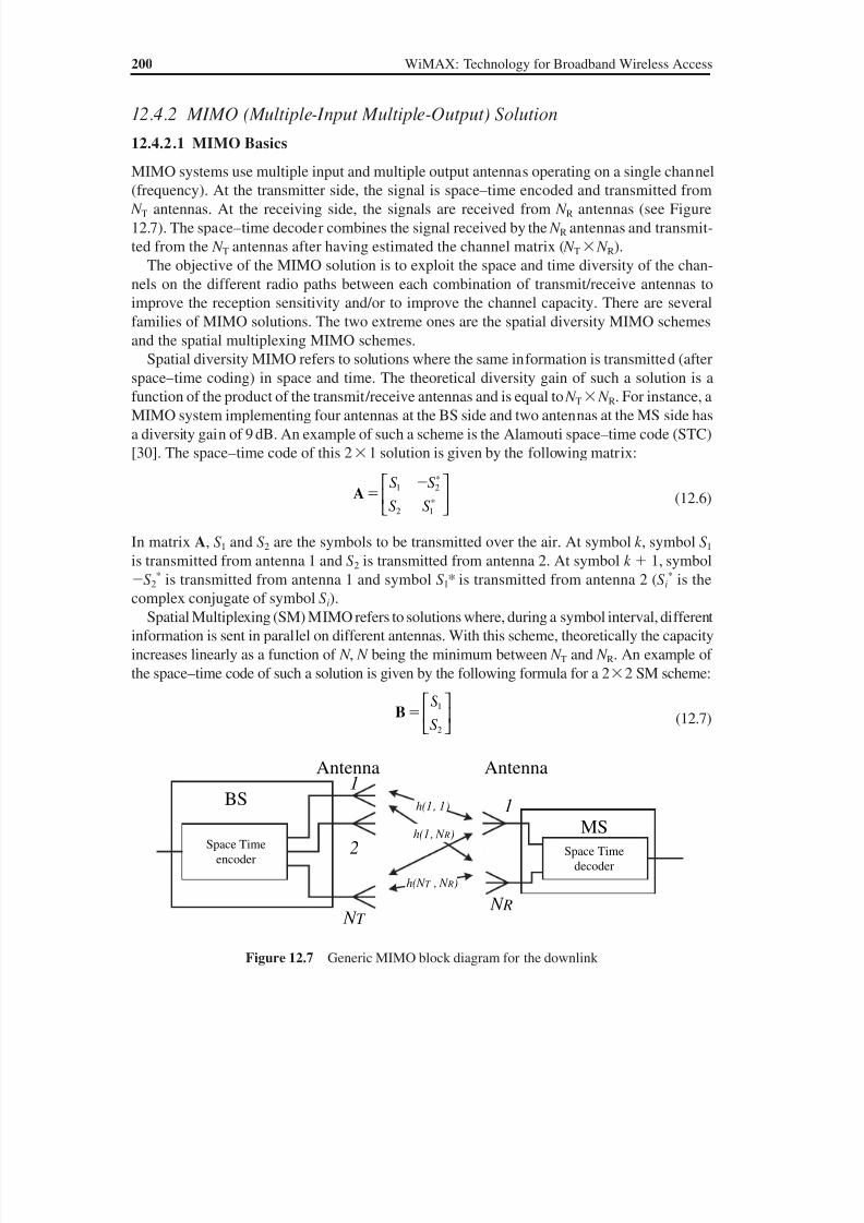
8/10/2019 WiMax-Tech for BBW Access
http://slidepdf.com/reader/full/wimax-tech-for-bbw-access 215/293
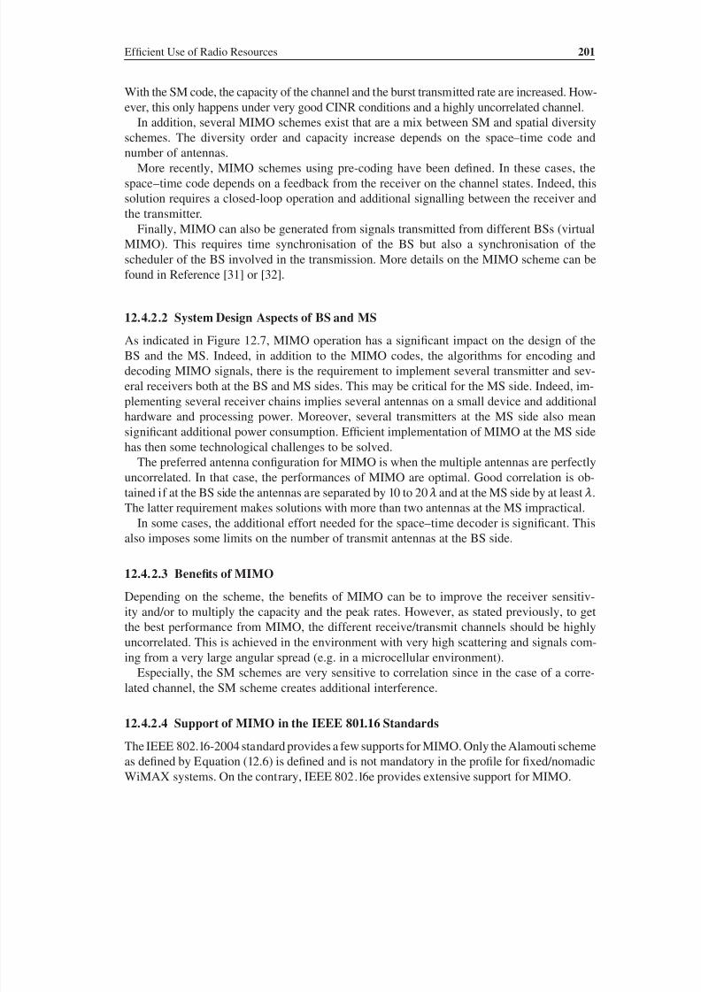
8/10/2019 WiMax-Tech for BBW Access
http://slidepdf.com/reader/full/wimax-tech-for-bbw-access 216/293
Ef ficient Use of Radio Resources 201
With the SM code, the capacity of the channel and the burst transmitted rate are increased. How-
ever, this only happens under very good CINR conditions and a highly uncorrelated channel.
In addition, several MIMO schemes exist that are a mix between SM and spatial diversity
schemes. The diversity order and capacity increase depends on the space–time code and
number of antennas.More recently, MIMO schemes using pre-coding have been defined. In these cases, the
space–time code depends on a feedback from the receiver on the channel states. Indeed, this
solution requires a closed-loop operation and additional signalling between the receiver and
the transmitter.
Finally, MIMO can also be generated from signals transmitted from different BSs (virtual
MIMO). This requires time synchronisation of the BS but also a synchronisation of the
scheduler of the BS involved in the transmission. More details on the MIMO scheme can be
found in Reference [31] or [32].
12.4.2.2 System Design Aspects of BS and MS
As indicated in Figure 12.7, MIMO operation has a significant impact on the design of the
BS and the MS. Indeed, in addition to the MIMO codes, the algorithms for encoding and
decoding MIMO signals, there is the requirement to implement several transmitter and sev-
eral receivers both at the BS and MS sides. This may be critical for the MS side. Indeed, im-
plementing several receiver chains implies several antennas on a small device and additional
hardware and processing power. Moreover, several transmitters at the MS side also mean
significant additional power consumption. Ef ficient implementation of MIMO at the MS side
has then some technological challenges to be solved.The preferred antenna configuration for MIMO is when the multiple antennas are perfectly
uncorrelated. In that case, the performances of MIMO are optimal. Good correlation is ob-
tained if at the BS side the antennas are separated by 10 to 20 m and at the MS side by at least m.
The latter requirement makes solutions with more than two antennas at the MS impractical.
In some cases, the additional effort needed for the space–time decoder is significant. This
also imposes some limits on the number of transmit antennas at the BS side.
12.4.2.3 Benefits of MIMO
Depending on the scheme, the benefits of MIMO can be to improve the receiver sensitiv-ity and/or to multiply the capacity and the peak rates. However, as stated previously, to get
the best performance from MIMO, the different receive/transmit channels should be highly
uncorrelated. This is achieved in the environment with very high scattering and signals com-
ing from a very large angular spread (e.g. in a microcellular environment).
Especially, the SM schemes are very sensitive to correlation since in the case of a corre-
lated channel, the SM scheme creates additional interference.
12.4.2.4 Support of MIMO in the IEEE 801.16 Standards
The IEEE 802.16-2004 standard provides a few supports for MIMO. Only the Alamouti scheme
as defined by Equation (12.6) is defined and is not mandatory in the profile for fixed/nomadic
WiMAX systems. On the contrary, IEEE 802.16e provides extensive support for MIMO.
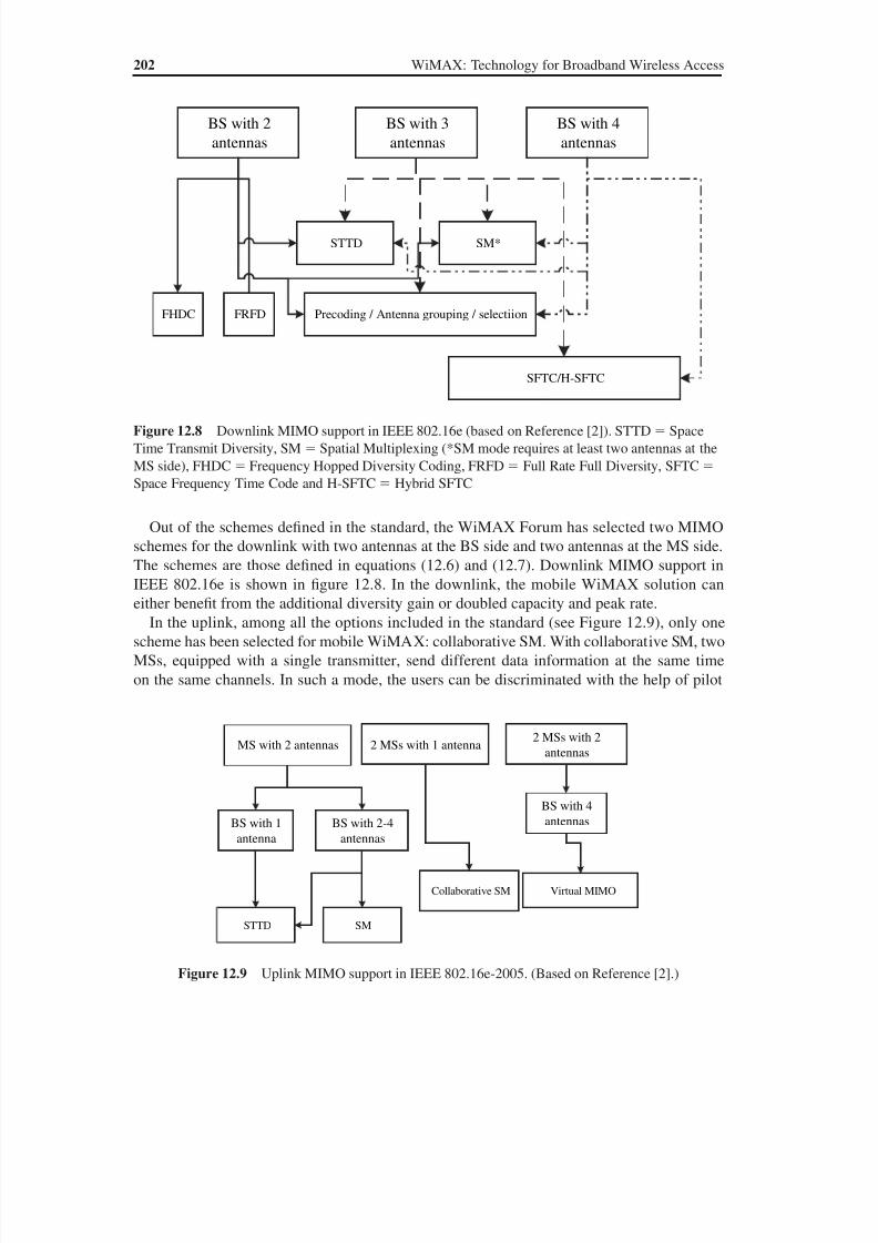
8/10/2019 WiMax-Tech for BBW Access
http://slidepdf.com/reader/full/wimax-tech-for-bbw-access 217/293
202 WiMAX: Technology for Broadband Wireless Access
Out of the schemes defined in the standard, the WiMAX Forum has selected two MIMO
schemes for the downlink with two antennas at the BS side and two antennas at the MS side.
The schemes are those defined in equations (12.6) and (12.7). Downlink MIMO support inIEEE 802.16e is shown in figure 12.8. In the downlink, the mobile WiMAX solution can
either benefit from the additional diversity gain or doubled capacity and peak rate.
In the uplink, among all the options included in the standard (see Figure 12.9), only one
scheme has been selected for mobile WiMAX: collaborative SM. With collaborative SM, two
MSs, equipped with a single transmitter, send different data information at the same time
on the same channels. In such a mode, the users can be discriminated with the help of pilot
Figure 12.9 Uplink MIMO support in IEEE 802.16e-2005. (Based on Reference [2].)
MS with 2 antennas2 MSs with 2
antennas
SMSTTD
Collaborative SM Virtual MIMO
BS with 1
antenna
2 MSs with 1 antenna
BS with 2-4
antennas
BS with 4
antennas
Figure 12.8 Downlink MIMO support in IEEE 802.16e (based on Reference [2]). STTD Space
Time Transmit Diversity, SM Spatial Multiplexing (*SM mode requires at least two antennas at the
MS side), FHDC Frequency Hopped Diversity Coding, FRFD Full Rate Full Diversity, SFTC
Space Frequency Time Code and H-SFTC Hybrid SFTC
BS with 2
antennas
BS with 3
antennas
BS with 4
antennas
SM*
FHDC
STTD
FRFD Precoding / Antenna grouping / selectiion
SFTC/H-SFTC

8/10/2019 WiMax-Tech for BBW Access
http://slidepdf.com/reader/full/wimax-tech-for-bbw-access 218/293
Ef ficient Use of Radio Resources 203
symbols, which use different tones for each user (each MS transmits half of the total available
pilots).
In the uplink, MIMO can improve the capacity of the mobile WiMAX system by providing
suf ficient signal quality. Of course, since the use of SM is sensitive to the radio condition, a
MIMO solution may include the solution to switch to the best MIMO mode depending on the
signal quality.
Indeed, MIMO operation implies that the signals transmitted over the air have a specific
format. In order to mix users operating with MIMO with other users in one frame, MIMO
zones are defined (indicated in the DL-MAP message). For instance, Figure 12.10 is an ex-
ample of a frame mixing MIMO and non-MIMO zones. In this figure, zone (1) includes the
common signalling channels and some downlink bursts (using a PUSC permutation). Zone
(2) is the MIMO zone for the downlink. Zone (3) is the zone in the uplink for users who can-
not use collaborative MIMO (e.g. because their estimated signal-to-interference level is too
weak). Zone (3) also includes common uplink signalling messages for ranging, fast feedback,
etc. Finally, zone (4) is the uplink MIMO zone.
12.4.3 About the Implementation of Advanced Antenna Technologies
As discussed in previous sections, beamforming and MIMO are key solutions to provide
spectral ef ficiency for a mobile WiMAX system, making it superior to the spectral ef ficiency
of other existing cellular systems. Also, both MIMO and AAS technologies (in particular
in the light of the choices made by the WiMAX Forum) have different and complementary
benefits.
Figure 12.10 Example of a frame with regions supporting the MIMO operation
F C H
R a n g i n g
S u b D L a n d U L M A P s
P r e a m b l e
C o m p r e s s
e d D L a n d U L M A P s
D L b u r s t s
STC enabled zone
F a s t f e e
d b a c k
UL
normal
bursts
STC enabled
zone
DL PUSC zone (1) UL PUSC zone (3) UL STC zone (4)DL STC zone (2)
8/10/2019 WiMax-Tech for BBW Access
http://slidepdf.com/reader/full/wimax-tech-for-bbw-access 219/293
204 WiMAX: Technology for Broadband Wireless Access
Beamforming (or AAS), since it provides link budget gains for both the uplink and the
downlink, is well suited for environments that are coverage-limited. For instance, compar-
ing a system implementing a two-branch receive diversity with a solution for beamforming
with four antenna elements can save between 40 and 50 % of radio sites. Beamforming could
then be recommended for the first phase of deployment of a mobile WiMAX. This corre-sponds to macrocell coverage where the signal at the BS side is received with really limited
angular spread (no more than 20–30), which is the preferred situation for beamforming
algorithms.
Also, using beamforming may enable mobile WiMAX solutions at 3.5 GHz to be deployed
since the extra gains provided by beamforming can compensate for the additional propaga-
tion losses due to transmission at a higher frequency band. As discussed previously, deploying
beamforming not only increases the coverage but also increases the offered capacity.
The mobile WiMAX solution does not provide a diversity gain in the uplink (which is the
weak link in WiMAX, as in most cellular systems). Consequently, MIMO solutions cannot
be deployed to improve the range in areas that are coverage-limited. However, MIMO can bedeployed advantageously in areas where the capacity demand is very high or where the peak
rate offer to the end user is very high. This can occur in hot-spot areas (e.g. a business area)
or indoor environments. Actually, these very dense environments do have the radio charac-
teristics that are favourable to MIMO. Indeed, in very dense areas, small cells with antennas
below the rooftop are usually deployed.
Presently, there is no single and universal deployment strategy for WiMAX, but the use
of antenna technology (either beamforming or MIMO or both) does provide significant dif-
ferentiation with other existing wireless systems.
12.5 Multicast Broadcast Services (MBS)
Multicast Broadcast Services (MBS) may be required when multiple MSs connected to
a BS receive the same information or when multiple BSs transmit the same information.
Indeed, this allows resource to be saved by allocating a single radio pipe for all users reg-
istered to the same service instead of allocating as many pipes as there are users. This is of
particular interest for the broadcast TV type of application where, at the same time, several
users under the same coverage area are connected to the same service (in this case, a TV
channel).
12.5.1 Multi-BS Access MBS
The mobile WiMAX system supports MBS as an optional feature for the BS. When the MBS
feature is supported, the Multi-BSs Access mode is implemented, as defined in the IEEE
802.16e standard [2].
In a Multi-BS MBS system, several BSs in the same geographical area transmit the
same broadcast/multicast messages at the same time on the same frequency channel. These
BSs actually belong to MBS_ZONE. An MBS_ZONE is a unique identifier, which is
transmitted from each BS of the set on the DCD message. An example of an MBS_ZONE
allocation is provided in Figure 12.11. It has to be noted that a BS may belong to different
MBS_ZONEs.
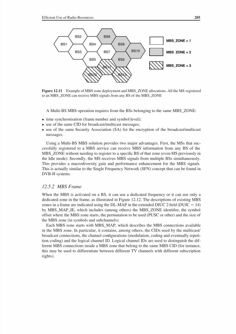
8/10/2019 WiMax-Tech for BBW Access
http://slidepdf.com/reader/full/wimax-tech-for-bbw-access 220/293
Ef ficient Use of Radio Resources 205
A Multi-BS MBS operation requires from the BSs belonging to the same MBS_ZONE:
• time synchronisation (frame number and symbol level);
• use of the same CID for broadcast/multicast messages;
• use of the same Security Association (SA) for the encryption of the broadcast/multicast
messages.
Using a Multi-BS MBS solution provides two major advantages. First, the MSs that suc-
cessfully registered to a MBS service can receive MBS information from any BS of the
MBS_ZONE without needing to register to a specific BS of that zone (even MS previously inthe Idle mode). Secondly, the MS receives MBS signals from multiple BSs simultaneously.
This provides a macrodiversity gain and performance enhancement for the MBS signals.
This is actually similar to the Single Frequency Network (SFN) concept that can be found in
DVB-H systems.
12.5.2 MBS Frame
When the MBS is activated on a BS, it can use a dedicated frequency or it can use only a
dedicated zone in the frame, as illustrated in Figure 12.12. The descriptions of existing MBS
zones in a frame are indicated using the DL-MAP in the extended DIUC 2 field (DUIC 14)
by MBS_MAP_IE, which includes (among others) the MBS_ZONE identifier, the symbol
offset where the MBS zone starts, the permutation to be used (PUSC or other) and the size of
the MBS zone (in symbols and subchannels).
Each MBS zone starts with MBS_MAP, which describes the MBS connections available
in the MBS zone. In particular, it contains, among others, the CIDs used by the multicast/
broadcast connections, the channel configurations (modulation, coding and eventually repeti-
tion coding) and the logical channel ID. Logical channel IDs are used to distinguish the dif-
ferent MBS connections inside a MBS zone that belong to the same MBS CID (for instance,
this may be used to differentiate between different TV channels with different subscription
rights).
Figure 12.11 Example of MBS zone deployment and MBS_ZONE allocations. All the MS registered
to an MBS_ZONE can receive MBS signals from any BS of the MBS_ZONE
BS1
BS2
BS3
BS4
BS5
BS7
BS6
BS8
BS9
BS10
BS11
BS13BS12
MBS_ZONE = 1
MBS_ZONE = 2
MBS_ZONE = 3

8/10/2019 WiMax-Tech for BBW Access
http://slidepdf.com/reader/full/wimax-tech-for-bbw-access 221/293
206 WiMAX: Technology for Broadband Wireless Access
The MBS PDUs in the MBS region follow the order of the combination of multicast CID/
logical channel CID, as described by the service association between the MS and the BS. Of
course, from the time when the MS goes into the Idle mode or when the MS moves across
different BS areas of the same MBS_ZONE there is no need for the MS to be registered to
the BS to receive the MBS content. The mapping between the multicast CID and the logicalchannel CID must be the same in the cells belonging to the same MBS_ZONE. The proce-
dure to provide consistency of the identities used by the MBS channels is beyond the scope
of the IEEE 802.16 standard.
Figure 12.12 Example of the 802.16 frame with the MBS service zone. The presence of the MBS
zone is indicated in the DL-MAP message (in a MBS_MAP_IE field). The exact details of the MBS
zone are then described in the MBS_MAP message at the beginning of the MBS zone
F C H
M B S_
M A P
R a n g i n g
P r e a m b l e
D L - M A P w i t h M B S_
M A P - I E
DL PUSC zone MBS PUSC zone UL PUSC zone
8/10/2019 WiMax-Tech for BBW Access
http://slidepdf.com/reader/full/wimax-tech-for-bbw-access 222/293
13.1 The Need for a Standardised WiMAX Architecture
13.1.1 Supporting Working Groups and Documents
The IEEE 802.16 standard only defines the PHY and MAC layers. Consequently, in order to ensure
intervendor internetwork interoperability, for operations such as roaming, it is important to define
standards over the widest range of interfaces and equipments, as in 3GPP and 3GPP2 mobile stan-
dards. Then, in addition to the alignment of the radio access features for multivendor interworking
between base stations and terminals based on the 802.16 standards [1,2], the WiMAX Forum char-
ter also aims to deliver a framework for a high-performance end-to-end IP network architecture to
support fixed, nomadic, portable and mobile users (see Table 13.1 for service type definitions).The WiMAX architecture is based on the use of standardised IP protocols and is compatible
with service frameworks such as the IP Multimedia Subsystem (IMS). Two working groups
from the WiMAX Forum organisation (see Chapter 2) define the architecture and associated
functionalities: the Network Working Group (NWG) creates the network specifications and
the Service Provider Working Group (SPWG) helps to define requirements and priorities.
The set of specifications issued by these two groups includes several alternatives for mapp-
ing different required functionalities to physical equipments, allowing at the same time added
value manufacturer-dependent implementation choices and also interoperability points at the
network level, thanks to standardised open interfaces (or reference points in the WiMAX
wording) [21, 10, 34]. The latest NWG drafts are publicly accessible at http://www.wimaxfo-rum.org/technology/documents.
The specifications are organised by release (currently, Release 1 will be finalised by Q3’06)
and consists of a set of three-stage documents:
• Stage 1 document defines the requirements for the WiMAX architecture.
• Stage 2 documents describe the network reference model, the reference points and also
include some informative parts for interworking between a WiMAX network and another
network (e.g. a DSL network) [21]. The WiMAX network architecture is evidently also
applicable to standalone deployments (not just for interworking scenarios).
13WiMAX ArchitectureWith the contribution of Jérôme Brouet, Alcatel, France
WiMAX: Technology for Broadband Wireless Access Loutfi Nuaymi
© 2007 John Wiley & Sons, Ltd. ISBN: 0-470-02808-4

8/10/2019 WiMax-Tech for BBW Access
http://slidepdf.com/reader/full/wimax-tech-for-bbw-access 223/293
208 WiMAX: Technology for Broadband Wireless Access
• Stage 3 documents define the details of the protocols and other procedures to be imple-
mented in a WiMAX end-to-end network [34].
13.1.2 High-level Architecture Requirements
The WiMAX reference architecture has been created having in mind various types of
requirements:
• a high-performance packet-based network with functional split, ensuring maximum flex-
ibility based on standard protocols from IEEE and IETF;
• the support of a full scale of services and applications;
• the support of roaming and interworking with other fixed/mobile networks.
In terms of services and applications, a WiMAX network is designed to be able to support:
• voice (using VoIP), multimedia (using IMS) and other mandatory regulatory services such
as emergency calls;
• access to a large variety of application service providers;
• interfacing with a variety of interworking and media gateways for translating legacy services
(e.g. circuit voice, MMS) to IP and to transport them over WiMAX radio access networks;
• delivery of IP MBS, multicast and broadcast services (see Chapter 12).
In addition, considering network interworking and roaming, several deployment scenarios
must be supported:
• loose coupling with existing wired (e.g. DSL) or wireless networks (e.g. 3GPP or 3GPP2
mobile networks);
• global roaming between WiMAX operators (this includes among others a consistent use
of the AAA, Authentication Authorization and Accounting, among WiMAX operators for
authentication and billing);
• a variety of user authentication methods (username/password, digital certificates, SIM based).
Table 13.1 WiMAX service definition. (Based on Reference [33].)
Service type Service area Speed Handover Comment
Fixed Single BS Stationary No; yet may involve
BS reselection dueto link conditions
Usually, fixed outdoor
terminals
Nomadicity Any BS Stationary No; yet may involve
BS reselection due
to link conditions
Indoor/Outdoor use;
usually self-install
Portability Any BS Mobile Yes Session continuity for non-
real-time applications
Simple mobility Any BS Mobile Yes Performance for non-real-
time applications and
some support of real-
time applications
Full mobility Any BS Mobile Yes Session continuity for real-time applications
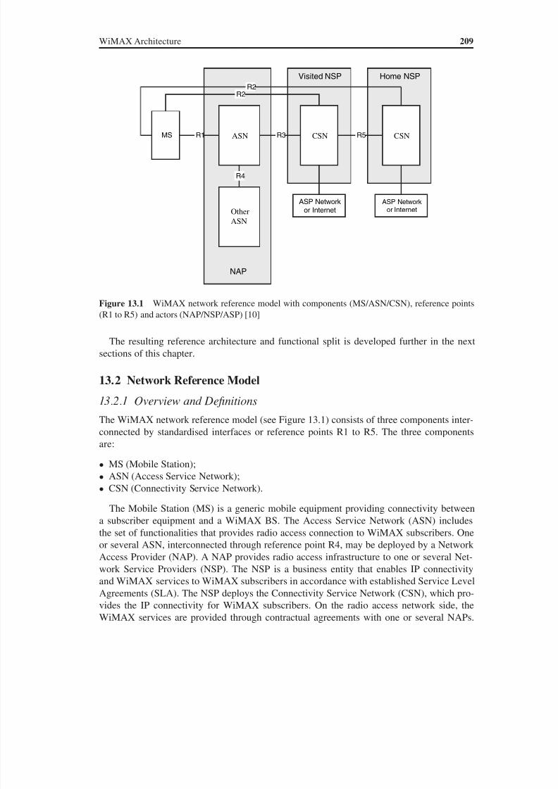
8/10/2019 WiMax-Tech for BBW Access
http://slidepdf.com/reader/full/wimax-tech-for-bbw-access 224/293
WiMAX Architecture 209
The resulting reference architecture and functional split is developed further in the next
sections of this chapter.
13.2 Network Reference Model
13.2.1 Overview and Definitions
The WiMAX network reference model (see Figure 13.1) consists of three components inter-
connected by standardised interfaces or reference points R1 to R5. The three components
are:
• MS (Mobile Station);
• ASN (Access Service Network);• CSN (Connectivity Service Network).
The Mobile Station (MS) is a generic mobile equipment providing connectivity between
a subscriber equipment and a WiMAX BS. The Access Service Network (ASN) includes
the set of functionalities that provides radio access connection to WiMAX subscribers. One
or several ASN, interconnected through reference point R4, may be deployed by a Network
Access Provider (NAP). A NAP provides radio access infrastructure to one or several Net-
work Service Providers (NSP). The NSP is a business entity that enables IP connectivity
and WiMAX services to WiMAX subscribers in accordance with established Service Level
Agreements (SLA). The NSP deploys the Connectivity Service Network (CSN), which pro-
vides the IP connectivity for WiMAX subscribers. On the radio access network side, the
WiMAX services are provided through contractual agreements with one or several NAPs.
Home NSPVisited NSP
NAP
ASN
Other
ASN
CSN CSN
ASP Network
or Internet
ASP Network
or Internet
MS R1 R3
R4
R5
R2
R2
Figure 13.1 WiMAX network reference model with components (MS/ASN/CSN), reference points
(R1 to R5) and actors (NAP/NSP/ASP) [10]
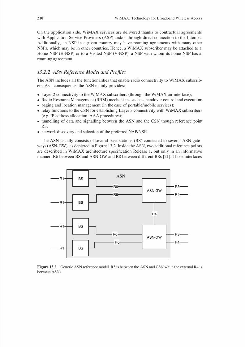
8/10/2019 WiMax-Tech for BBW Access
http://slidepdf.com/reader/full/wimax-tech-for-bbw-access 225/293
210 WiMAX: Technology for Broadband Wireless Access
On the application side, WiMAX services are delivered thanks to contractual agreements
with Application Service Providers (ASP) and/or through direct connection to the Internet.
Additionally, an NSP in a given country may have roaming agreements with many other
NSPs, which may be in other countries. Hence, a WiMAX subscriber may be attached to a
Home NSP (H-NSP) or to a Visited NSP (V-NSP), a NSP with whom its home NSP has aroaming agreement.
13.2.2 ASN Reference Model and Profiles
The ASN includes all the functionalities that enable radio connectivity to WiMAX subscrib-
ers. As a consequence, the ASN mainly provides:
• Layer 2 connectivity to the WiMAX subscribers (through the WiMAX air interface);
• Radio Resource Management (RRM) mechanisms such as handover control and execution;
• paging and location management (in the case of portable/mobile services);• relay functions to the CSN for establishing Layer 3 connectivity with WiMAX subscribers
(e.g. IP address allocation, AAA procedures);
• tunnelling of data and signalling between the ASN and the CSN though reference point
R3;
• network discovery and selection of the preferred NAP/NSP.
The ASN usually consists of several base stations (BS) connected to several ASN gate-
ways (ASN-GW), as depicted in Figure 13.2. Inside the ASN, two additional reference points
are described in WiMAX architecture specification Release 1, but only in an informative
manner: R6 between BS and ASN-GW and R8 between different BSs [21]. Those interfaces
ASN
R6
R6
R6
R6
R4
BS
BS
BS
BS
ASN-GW
ASN-GW
R1
R1
R1
R1
R3
R3
R4
R4
Figure 13.2 Generic ASN reference model. R3 is between the ASN and CSN while the external R4 is
between ASNs
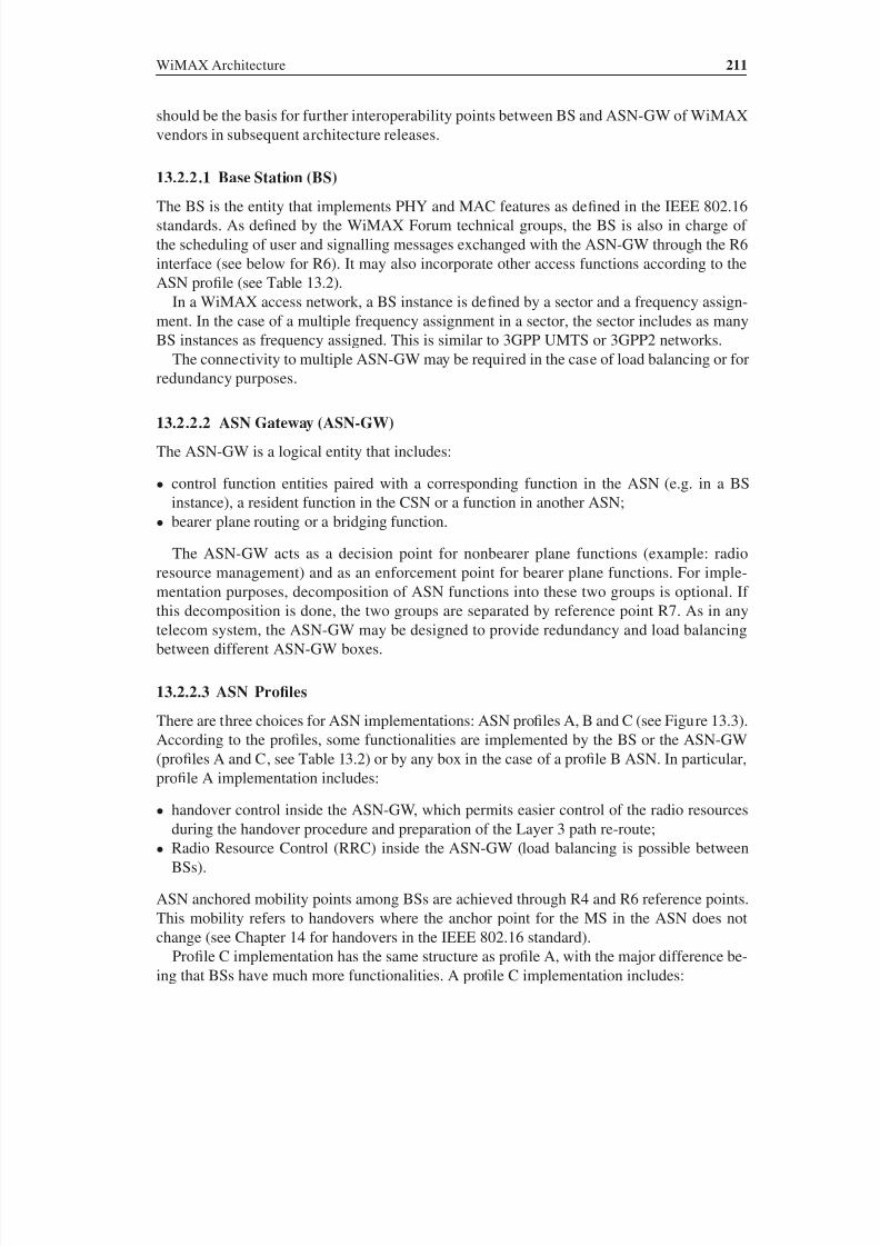
8/10/2019 WiMax-Tech for BBW Access
http://slidepdf.com/reader/full/wimax-tech-for-bbw-access 226/293
WiMAX Architecture 211
should be the basis for further interoperability points between BS and ASN-GW of WiMAX
vendors in subsequent architecture releases.
13.2.2.1 Base Station (BS)
The BS is the entity that implements PHY and MAC features as defined in the IEEE 802.16
standards. As defined by the WiMAX Forum technical groups, the BS is also in charge of
the scheduling of user and signalling messages exchanged with the ASN-GW through the R6
interface (see below for R6). It may also incorporate other access functions according to the
ASN profile (see Table 13.2).
In a WiMAX access network, a BS instance is defined by a sector and a frequency assign-
ment. In the case of a multiple frequency assignment in a sector, the sector includes as many
BS instances as frequency assigned. This is similar to 3GPP UMTS or 3GPP2 networks.
The connectivity to multiple ASN-GW may be required in the case of load balancing or for
redundancy purposes.
13.2.2.2 ASN Gateway (ASN-GW)
The ASN-GW is a logical entity that includes:
• control function entities paired with a corresponding function in the ASN (e.g. in a BS
instance), a resident function in the CSN or a function in another ASN;
• bearer plane routing or a bridging function.
The ASN-GW acts as a decision point for nonbearer plane functions (example: radio
resource management) and as an enforcement point for bearer plane functions. For imple-mentation purposes, decomposition of ASN functions into these two groups is optional. If
this decomposition is done, the two groups are separated by reference point R7. As in any
telecom system, the ASN-GW may be designed to provide redundancy and load balancing
between different ASN-GW boxes.
13.2.2.3 ASN Profiles
There are three choices for ASN implementations: ASN profiles A, B and C (see Figure 13.3).
According to the profiles, some functionalities are implemented by the BS or the ASN-GW
(profiles A and C, see Table 13.2) or by any box in the case of a profile B ASN. In particular,profile A implementation includes:
• handover control inside the ASN-GW, which permits easier control of the radio resources
during the handover procedure and preparation of the Layer 3 path re-route;
• Radio Resource Control (RRC) inside the ASN-GW (load balancing is possible between
BSs).
ASN anchored mobility points among BSs are achieved through R4 and R6 reference points.
This mobility refers to handovers where the anchor point for the MS in the ASN does not
change (see Chapter 14 for handovers in the IEEE 802.16 standard).
Profile C implementation has the same structure as profile A, with the major difference be-
ing that BSs have much more functionalities. A profile C implementation includes:
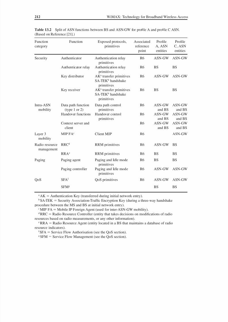
8/10/2019 WiMax-Tech for BBW Access
http://slidepdf.com/reader/full/wimax-tech-for-bbw-access 227/293
212 WiMAX: Technology for Broadband Wireless Access
Table 13.2 Split of ASN functions between BS and ASN-GW for profile A and profile C ASN.
(Based on Reference [21].)
Function
category
Function Exposed protocols,
primitives
Associated
reference
point
Profile
A, ASN
entities
Profile
C, ASN
entities
Security Authenticator Authentication relay
primitives
R6 ASN-GW ASN-GW
Authenticator relay Authentication relay
primitives
R6 BS BS
Key distributor AKa transfer primitives
SA-TEKb handshake
primitives
R6 ASN-GW ASN-GW
Key receiver AKa transfer primitives
SA-TEKb handshake
primitives
R6 BS BS
Intra-ASN
mobility
Data path function
(type 1 or 2)
Data path control
primitives
R6 ASN-GW
and BS
ASN-GW
and BS
Handover functions Handover control
primitives
R6 ASN-GW
and BS
ASN-GW
and BS
Context server and
client
R6 ASN-GW
and BS
ASN-GW
and BS
Layer 3
mobility
MIP FAc Client MIP R6 ASN-GW
Radio resource
management
RRCd RRM primitives R6 ASN-GW BS
RRAe RRM primitives R6 BS BS
Paging Paging agent Paging and Idle mode
primitives
R6 BS BS
Paging controller Paging and Idle mode
primitives
R6 ASN-GW ASN-GW
QoS SFAf QoS primitives R6 ASN-GW ASN-GW
SFMg BS BS
a AKAuthentication Key (transferred during initial network entry).b SA-TEK Security Association-Traf fic Encryption Key (during a three-way handshake
procedure between the MS and BS at initial network entry).c MIP FAMobile IP Foreign Agent (used for inter-ASN-GW mobility).d RRC Radio Resource Controller (entity that takes decisions on modifications of radio
resources based on radio measurements, or any other information).e RRA Radio Resource Agent (entity located in a BS that maintains a database of radio
resource indicators).f SFA Service Flow Authorisation (see the QoS section).g SFM Service Flow Management (see the QoS section).
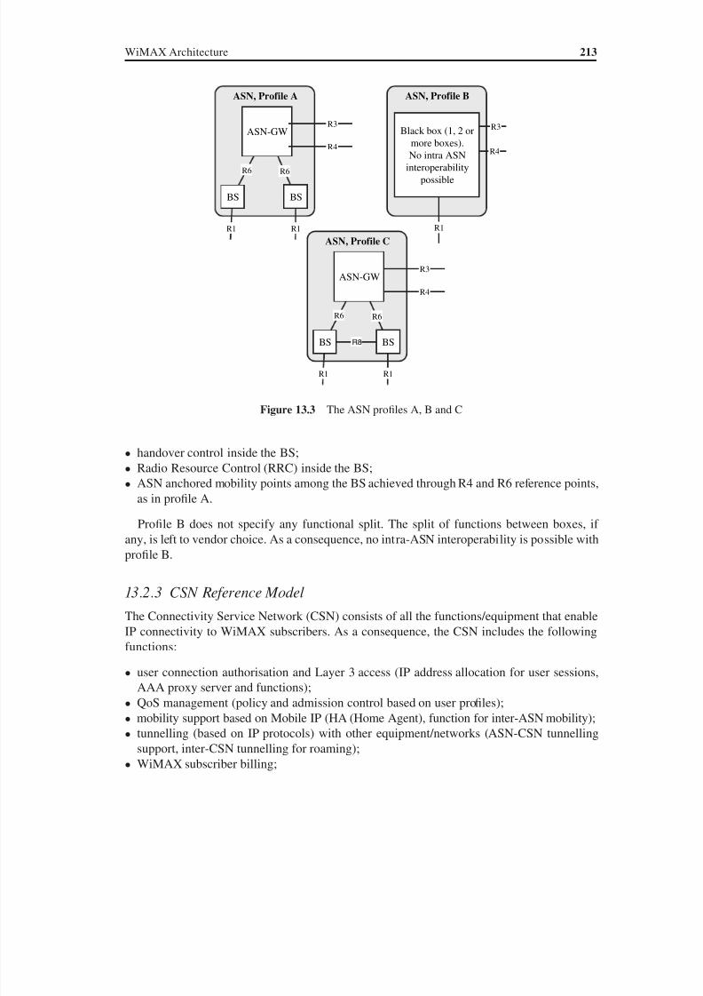
8/10/2019 WiMax-Tech for BBW Access
http://slidepdf.com/reader/full/wimax-tech-for-bbw-access 228/293
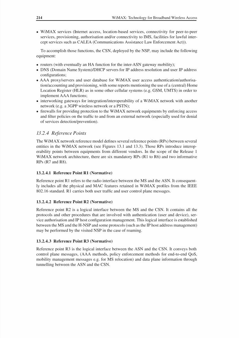
8/10/2019 WiMax-Tech for BBW Access
http://slidepdf.com/reader/full/wimax-tech-for-bbw-access 229/293
214 WiMAX: Technology for Broadband Wireless Access
• WiMAX services (Internet access, location-based services, connectivity for peer-to-peer
services, provisioning, authorisation and/or connectivity to IMS, facilities for lawful inter-
cept services such as CALEA (Communications Assistance Law Enforcement Act)).
To accomplish those functions, the CSN, deployed by the NSP, may include the followingequipment:
• routers (with eventually an HA function for the inter-ASN gateway mobility);
• DNS (Domain Name System)/DHCP servers for IP address resolution and user IP address
configurations;
• AAA proxy/servers and user database for WiMAX user access authentication/authorisa-
tion/accounting and provisioning, with some reports mentioning the use of a (central) Home
Location Register (HLR) as in some other cellular systems (e.g. GSM, UMTS) in order to
implement AAA functions;
• interworking gateways for integration/interoperability of a WiMAX network with anothernetwork (e.g. a 3GPP wireless network or a PSTN);
• firewalls for providing protection to the WiMAX network equipments by enforcing access
and filter policies on the traf fic to and from an external network (especially used for denial
of services detection/prevention).
13.2.4 Reference Points
The WiMAX network reference model defines several reference points (RPs) between several
entities in the WiMAX network (see Figures 13.1 and 13.3). Those RPs introduce interop-
erability points between equipments from different vendors. In the scope of the Release 1
WiMAX network architecture, there are six mandatory RPs (R1 to R6) and two informative
RPs (R7 and R8).
13.2.4.1 Reference Point R1 (Normative)
Reference point R1 refers to the radio interface between the MS and the ASN. It consequent-
ly includes all the physical and MAC features retained in WiMAX profiles from the IEEE
802.16 standard. R1 carries both user traf fic and user control plane messages.
13.2.4.2 Reference Point R2 (Normative)
Reference point R2 is a logical interface between the MS and the CSN. It contains all the
protocols and other procedures that are involved with authentication (user and device), ser-
vice authorisation and IP host configuration management. This logical interface is established
between the MS and the H-NSP and some protocols (such as the IP host address management)
may be performed by the visited NSP in the case of roaming.
13.2.4.3 Reference Point R3 (Normative)
Reference point R3 is the logical interface between the ASN and the CSN. It conveys both
control plane messages, (AAA methods, policy enforcement methods for end-to-end QoS,
mobility management messages e.g. for MS relocation) and data plane information through
tunnelling between the ASN and the CSN.
8/10/2019 WiMax-Tech for BBW Access
http://slidepdf.com/reader/full/wimax-tech-for-bbw-access 230/293
WiMAX Architecture 215
13.2.4.4 Reference Point R4 (Normative)
Reference point R4 interconnects two ASNs (ASN profile B) or two ASN-GWs (ASN profiles
A or C). It conveys both control and data plane messages, especially during the handover of a
WiMAX user between ASNs/ASN-GWs or during location update procedures in the Idle mode.This RP is presently the only interoperable point between ASNs from different vendors.
The tunnelling method recommended is to use IP in IP tunnelling mode for R4 based on
the GRE (Generic Routing Encapsulation) protocol [35].
13.2.4.5 Reference Point R5 (Normative)
Reference point R5 is the interface interconnecting two CSNs. It consists of the set of control
and data plane methods between the CSN in the visited NSP and in the home NSP.
13.2.4.6 Reference Point R6 (Normative for Profiles A and C)
Reference point R6 is normative in WiMAX architecture Release 1 in the context of specific
ASN profiles. In Release 1, ASN profiles A and C decompose the ASN into BS and ASN GW.
In each case, normative procedures over R6 are specified in Release 1. R6, of course, is not
applicable to profile B.
Reference point R6 connects the BS and the ASN-GW. It conveys both control messages
(for data path establishment, modification, control, release in accordance with MS mobility)
and data plane (intra-ASN data path between BS and ASN-GW) information. The tunnelling
method used is GRE, MPLS or VLAN (other tunnelling methods may be proposed in a later
phase as well). This interface can also convey, in combination with R4, the MAC state informa-
tion carried by the R8 reference point when R8 interoperability between BSs is not available.
13.2.4.7 Other Informative Reference Points
In the ASN, there are currently two additional interfaces (R7 and R8) defined for further in-
teroperability points in the scope of the next WiMAX architecture releases. Those interfaces
are only informative in the frame of WiMAX architecture Release 1.
Reference point R7 is an optional logical interface between the decision function and the
enforcement function in the ASN-GW.
Reference point R8 is a logical interface between BSs. It conveys the control plane flow
exchange that is used for enabling a fast and ef ficient handover between BSs. Optionally, R8may also convey data plane information during the handover phase. It should be noted that a
direct physical interface is not actually required between BSs. The R8 methods can indeed be
conveyed through, for example, the ASN-GW.
13.3 Network Functionalities
This section describes the main functions achieved by the WiMAX end-to-end system.
13.3.1 Network Discovery and Selection
This function is required for nomadic, portable and mobile WiMAX services (see Table 13.1)
where in the same geographical area the MS may have radio coverage access to an ASN
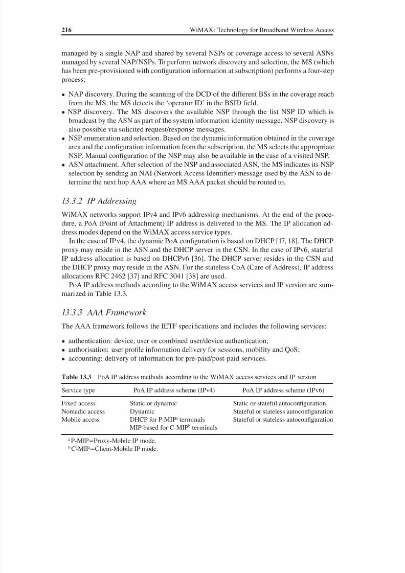
8/10/2019 WiMax-Tech for BBW Access
http://slidepdf.com/reader/full/wimax-tech-for-bbw-access 231/293
8/10/2019 WiMax-Tech for BBW Access
http://slidepdf.com/reader/full/wimax-tech-for-bbw-access 232/293
8/10/2019 WiMax-Tech for BBW Access
http://slidepdf.com/reader/full/wimax-tech-for-bbw-access 233/293
14Mobility, Handover andPower-Save Modes
14.1 Handover Considerations
One of the major goals of the 802.16e amendment is to introduce mobility in WiMAX. Con-
sequently, mobile WiMAX profiles are based on 802.16e. Mobility is based on handover.
Handover operation (sometimes also known as ‘handoff’) is the fact that a mobile user goes
from one cell to another without interruption of the ongoing session (whether a phone call,
data session or other). The handover can be due to mobile subscriber moves, to radio channel
condition changes or to cell capacity considerations. Handover is a mandatory feature of a
cellular network. In this chapter the handover (HO) is described as defined in 802.16e.
In 802.16e, the two known generic types of handover are defined:
• Hard handover, also known as break-before-make. The subscriber mobile station (MS)
stops its radio link with the first BS before establishing its radio link with the new BS. This
is a rather simple handover.
• Soft handover, also known as make-before-break. The MS establishes its radio link with a
new BS before stopping its radio link with the first BS. The MS may have two or more links
with two or more BSs, which gives the soft handover state. The soft handover is evidently
faster than the hard handover.
Two types of soft handover are then defined in 802.16e [2]:
• Fast BS Switching (FBSS). This is a state where the MS may rapidly switch from one BS to
another. The switch is fast because the MS makes it without realising the complete network
entry procedure with regard to the new BS.
• Macro Diversity HandOver (MDHO). Transmissions are between the MS and more than
one BS.
In the mobile WiMAX profiles, only the hard handover is mandatory. The FBSS and MDHO
are optional. The 802.16 standard also indicates that the support of the MDHO or FBSS is
optional for both the MS and the BS.
WiMAX: Technology for Broadband Wireless Access Loutfi Nuaymi
© 2007 John Wiley & Sons, Ltd. ISBN: 0-470-02808-4

8/10/2019 WiMax-Tech for BBW Access
http://slidepdf.com/reader/full/wimax-tech-for-bbw-access 234/293
220 WiMAX: Technology for Broadband Wireless Access
Handover has challenging objectives (see Section 13.1 for handover requirements as a
function of the WiMAX access type). First, it has to be fast enough, of the order of 50 ms or
150 ms. There are also security requirements, as some attacks are possible at the occasion
of the handover procedure. Finally, the handover does not have only Layer 2 considerations.
Layer 3 considerations are also needed, as mentioned in Chapter 13. Hence, the handover isnot independent of the architecture.
14.2 Network Topology Acquisition
14.2.1 Network Topology Advertisement
A BS broadcasts information about the network topology using the MOB_NBR-ADV (Neigh-
bour ADVertisement) MAC management message [2]. This message provides channel infor-
mation about neighbouring BSs normally provided by each BS’s own DCD/UCD message
transmissions. The MOB_NBR-ADV does not contain all the information of neighbouringBSs, UCD and DCD. The standard indicates that a BS may obtain that information over
the backbone and that availability of this information facilitates MS synchronisation with
neighbouring BS by removing the need to monitor transmission from the neighbouring (han-
dover target) BS for DCD/UCD broadcasts. The BSs will keep mapping tables of neighbour
BS MAC addresses and neighbour BS indexes transmitted through the MOB_NBR-ADV
message, for each configuration change count, which has the same function as for the DCD
message.
BSs supporting mobile functionality must be capable of transmitting a MOB_NBR-ADV
MAC management message at a periodic interval to identify the network and define the char-
acteristics of the neighbour BS to a potential MS seeking initial network entry or handover.
The standard indicates that the maximum value of this period is 30 seconds.
14.2.2 MS Scanning of Neighbour BSs
A scanning interval is defined as the time during which the MS scans for an available BS
[2]. A BS may allocate time intervals to the MS for the purpose of MS seeking and monitor-
ing suitability of neighbour BSs as targets for a handover. MS scanning of neighbour BSs is
based on the following MAC Management messages: MOB_SCN-REQ, SCaNning interval
allocation REQuest, MOB_SCN-RSP, SCaNning interval allocation Response, MOB_SCN-
REP and SCaNning result REPort.
The MOB_SCN-REQ message is sent by the MS to request a scanning interval for the
purpose of seeking available BSs and determining their suitability as targets for HO. In the
MOB_SCN-REQ message the MS indicates a group of neighbour BSs for which only Scan-
ning or Scanning with Association are requested by the MS. The Neighbour _ BS_ Index of the
MOB_SCN-REQ message corresponds to the position of BSs in the MOB_NBR-ADV mes-
sage. In this message, the MS may also request the scanning allocation to perform scanning
or noncontention Association ranging. Association is an optional initial ranging procedure
occurring during the scanning interval with respect to one of the neighbour BSs (see the
following section).
Upon reception of the MOB_SCN-REQ message, the BS responds with a MOB_SCN-
RSP message. The MOB_SCN-RSP message can also be unsolicited. The MOB_SCN-RSP
8/10/2019 WiMax-Tech for BBW Access
http://slidepdf.com/reader/full/wimax-tech-for-bbw-access 235/293
Mobility, Handover and Power-Save Modes 221
message either grants the requesting MS a scanning interval that is at least as long as that
requested by the MS or denies the request. In the MOB_SCN-RSP message the BS indicates
a group of neighbour BSs for which only Scanning or Scanning with Association are recom-
mended by the BS.
Following reception of a MOB_SCN-RSP message granting the request, an MS may scanfor one or more BSs during the time interval allocated in the message. When a BS is identified
through scanning, the MS may attempt to synchronise with its downlink transmissions and
estimate the quality of the PHY channel.
The BS may negotiate over the backbone with a BS Recommended for Association (in the
MOB_SCN-REQ message) the allocation of unicast ranging opportunities. Then the MS will
be informed on Rendez vous time to conduct Association ranging with the Recommended
BS. When conducting initial ranging to a BS Recommended for Association, the MS uses an
allocated unicast ranging opportunity, if available.
The serving BS may buffer incoming data addressed to the MS during the scanning inter-
val and transmit that data after the scanning interval during any interleaving interval or afterexit of the Scanning mode. When the Report mode is 0b10 (i.e. event-triggered) in the most
recently received MOB_SCN-RSP, the MS scans all the BSs within the Recommended BS list
of this message and then transmits a MOB_SCN-REP message to report the scanning results
to its serving BS after each scanning period at the time indicated in the MOB_SCN-RSP mes-
sage. The MS may transmit a MOB_SCN-REP message to report the scanning results to its
serving BS at any time. The message will be transmitted on the Primary Management CID.
14.2.3 Association Procedure
Association is an optional initial ranging procedure occurring during the scanning interval
with respect to one of the neighbour BSs [2]. The function of Association is to enable the MS
to acquire and record ranging parameters and service availability information for the purpose
of proper selection of a handover target BS and/or expediting a potential future handover to a
target BS. Recorded ranging parameters of an Associated BS may be further used for setting
initial ranging values in future ranging events during a handover.
Upon completion of a successful MS initial ranging of a BS, if the RNG-RSP message (sent
by the BS) contains a service level prediction parameter set to 2, the MS may mark the BS
as Associated in its MS local Association table of identities, recording elements of the RNG-
RSP to the MS local Association table and setting an appropriate ageing timer.There are three levels of Association as follows:
• Association Level 0: Scan/Association without coordination. The serving BS and the
MS negotiate the Association duration and intervals (via MOB_SCN-REQ). The serving
BS allocates periodic intervals where the MS may range neighbouring BSs. The target
BS has no knowledge of the MS. The MS uses the target BS contention-based ranging
allocations.
• Association Level 1: Association with coordination. Unilaterally or upon request of the MS
(through the MOB_SCN-REQ message), the serving BS provides Association parameters
to the MS and coordinates Association between the MS and neighbouring BSs. The target
BS reserves a CDMA initial ranging code and an initial ranging slot (transmission opportu-
nity) in a specified dedicated ranging region (rendezvous time). The neighbouring BS may
8/10/2019 WiMax-Tech for BBW Access
http://slidepdf.com/reader/full/wimax-tech-for-bbw-access 236/293
222 WiMAX: Technology for Broadband Wireless Access
assign the same code or transmission opportunity to more than one MS, but not both. There
is no potential for collision of transmissions from different MSs.
• Association Level 2: network assisted association reporting. The MS may request to per-
form Association with network assisted Association reporting by sending the MOB_SCN-
REQ message, including a list of neighbouring BSs, to the serving BS with scanningtype 0b011. The serving BS may also request this type of Association unilaterally by
sending the MOB_SCN-RSP message with the proper indication. The serving BS will
then coordinate the Association procedure with the requested neighbouring BSs in a fash-
ion similar to Association Level 1. With Level 2, the MS is only required to transmit the
CDMA ranging code to the neighbour BSs. The MS does not wait for RNG-RSP from
the neighbour BSs. Instead, the RNG-RSP information on PHY offsets is sent by each
neighbour BS to the serving BS over the backbone. The serving BS may aggregate all
ranging information into a single MOB_ASC_REPORT, MOB_ASC-REP, Association
result REPort, message.
14.2.4 CDMA Handover Ranging and Automatic Adjustment
For OFDMA PHY, 802.16e defines the handover ranging [2]. An MS that wishes to perform
handover ranging must take a process similar to that defined in the initial ranging section
with the following modifications. In the CDMA handover ranging process, the CDMA han-
dover ranging code is used instead of the initial ranging code. The code is selected from the
handover ranging domain. The handover ranging codes are used for ranging with a target BS
during the handover. Alternatively, if the BS is pre-notified for the upcoming handover MS,
it may provide bandwidth allocation information to the MS using Fast_Ranging_IE to send
an RNG-REQ message.
14.3 The Handover Process
The 802.16 standard states that the handover decision algorithm is beyond its scope. The
WiMAX Forum documents do not select a handover algorithm either. Only the framework
is defined. The MS, using its current information on the neighbour BS or after a request
to obtain such information (see the previous section), evaluates its interest in a potential
handover with a target BS. Once the handover decision is taken by either the serving BS or
the MS, a notification is sent over the MOB_BSHO-REQ (BS Handover REQuest) or the
MOB_MSHO-REQ (MS Handover REQuest) MAC management messages, depending on
the handover decision maker: the BS or MS. The handover process steps are described in the
following.
The handover process is made of five stages which are summarized in Figure 14.1. The HO
process stages are described in the following sections [2].
14.3.1 Cell Reselection
Cell reselection [2] refers to the process of an MS scanning and/or association with one or
more BS in order to determine their suitability, along with other performance considerations,
as a handover target. The MS may use neighbour BS information acquired from a decoded
MOB_NBR-ADV message or may make a request to schedule scanning intervals or sleep
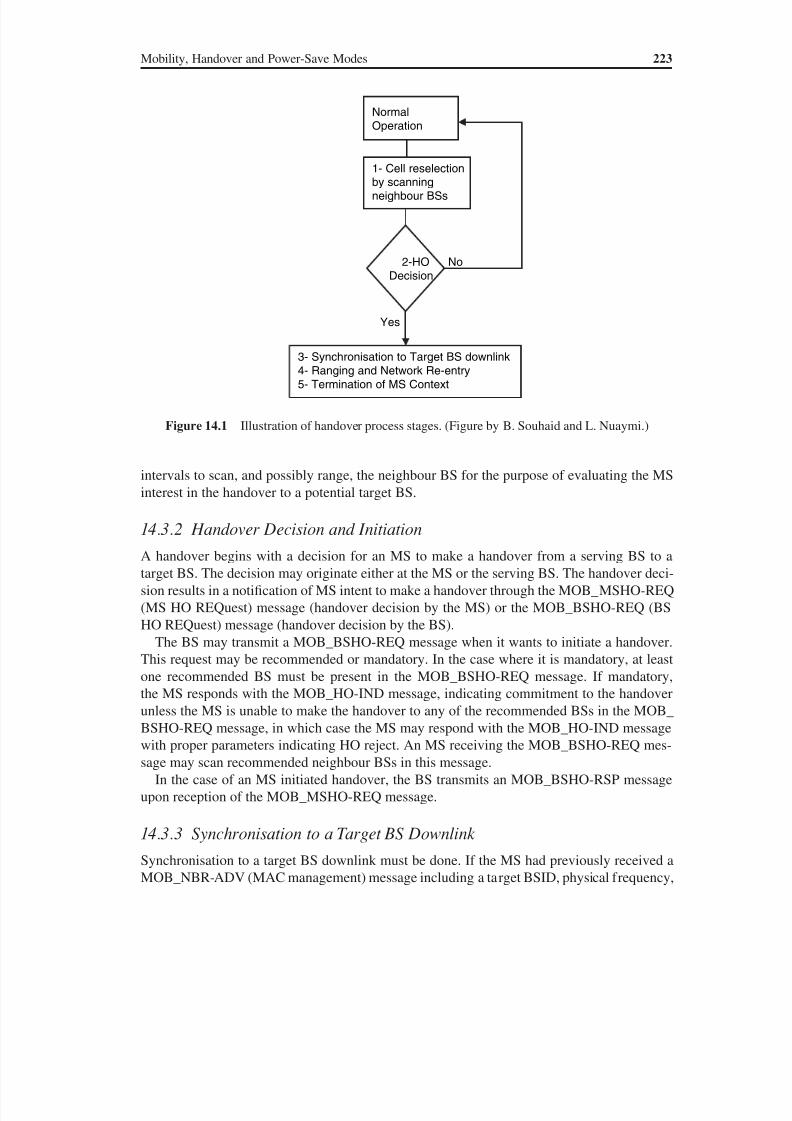
8/10/2019 WiMax-Tech for BBW Access
http://slidepdf.com/reader/full/wimax-tech-for-bbw-access 237/293

8/10/2019 WiMax-Tech for BBW Access
http://slidepdf.com/reader/full/wimax-tech-for-bbw-access 238/293
224 WiMAX: Technology for Broadband Wireless Access
DCD and UCD, this process may be shortened. If the target BS had previously received han-
dover notification from a serving BS over the backbone, then the target BS may allocate a
non-contention-based initial ranging opportunity.
14.3.4 Ranging and Network Re-entryThe MS and the target BS must conduct handover ranging. Network re-entry proceeds from
the initial ranging step in the Network Entry process (see Chapter 11): negotiate basic capabil-
ities, PKM authentication phase, TEK establishment phase, registration (the BS may send an
unsolicited REG-RSP message with updated capabilities information or skip the REG-RSP
message when there is no TLV information to be updated) and the other following Network
Entry optional steps (IP connectivity, etc.).
Network re-entry may be shortened by target BS possession of MS information
obtained from the serving BS over the backbone network. Depending on the amount of
that information, the target BS may decide to skip one or several of the Network Entry
steps (Figure 14.2). Handover ranging can then be a simplified version of initial ranging.To notify an MS seeking handover of possible omission of re-entry process management
messages during the current handover attempt (due to the availability of MS service and
operational context information obtained over the backbone network), the target BS must
place, in the RNG-RSP message, an HO Process Optimisation TLV indicating which
re-entry management messages may be omitted. The MS completes the processing of all
indicated messages before entering Normal Operation with the target BS.
Regardless of having received MS information from a serving BS, the target BS may
request MS information from the backbone network.
14.3.5 Termination of MS Context
This is the final step of a handover. Termination of the MS context is defined as the serving
BS termination of the context of all connections belonging to the MS and the discarding of
the context associated with them, i.e. information in queues, ARQ state machine, counters,
timers, header suppression information, etc. This is accomplished by sending the MOB_HO-
IND message with the HO_IND_type value indicating a serving BS release.
14.3.6 Handover Cancellation
An MS may cancel HO at any time prior to expiration of the Resource_Retain_Time in-
terval after transmission of the MOB_HO-IND message. Resource_Retain_Time is one of
* Negotiate Basic Capabilities* Authorisation* Registration
* Establish service flows
Network re-entry steps
Some steps can be shortened by targetBS possession of MS information
obtained from serving BS over
the backbone network
Figure 14.2 Summary of network re-entry steps
8/10/2019 WiMax-Tech for BBW Access
http://slidepdf.com/reader/full/wimax-tech-for-bbw-access 239/293
Mobility, Handover and Power-Save Modes 225
the parameters exchanged during the registration procedure (part of Network Entry). The
standard [2] indicates that Resource_Retain_Time is a multiple of 100 milliseconds and that
200 milliseconds is recommended as default.
14.4 Fast BS Switching (FBSS) and Macro Diversity Handover (MDHO)
14.4.1 Diversity Set
There are several conditions that are required to the diversity BSs featured in FBSS and
MDHO procedures. These conditions are listed below [2]:
• The BSs are synchronised based on a common time source and have synchronised frames.
• The frames sent by the BSs from the diversity set arrive at the MS within the prefix interval,
i.e. transmission delay cyclic prefix.
• The BSs operate at same frequency channel.• The BSs are required to share or transfer MAC context. Such context includes all informa-
tion MS and BS normally exchange during Network Entry, particularly the authentication
state, so that an MS authenticated/registered with one of the BSs from the diversity set BSs
is automatically authenticated/registered with other BSs from the same diversity set. The
context also includes a set of service flows and corresponding mapping to connections as-
sociated with the MS, current authentication and encryption keys associated with the con-
nections. There are also BS conditions specific to MDHO (see below).
An MS may scan the neighbour BSs and then select BSs that are suitable to be included in
the diversity set. The MS reports the selected BSs and the diversity set update procedure isperformed by the BS and the MS. After an MS or BS has initiated a diversity set update using
MOB_MSHO/BSHO-REQ, the MS may cancel the diversity set update at any time. This can-
cellation is made through transmission of an MOB_HO-IND with proper parameters. The BS
may reconfigure the diversity set list and retransmit the MOB_BSHO-RSP message to the MS.
In an MS diversity set, a member identifier, TEMP_BSID, is assigned to each BS in the
diversity set.
14.4.2 Different Types of BS for a Given MS
Before getting into the details of make-before-break handover algorithms, FBSS and MDHO,the different types of BS for a given MS are summarized:
• Serving BS. The serving BS is the BS with which the MS has most recently completed
registration at the initial Network Entry or during a handover.
• Neighbour BS. A neighbour BS is a BS (other than the serving BS) whose downlink trans-
mission can be (relatively well) received by the MS.
• Target BS. This is the BS that an MS intends to be registered with at the end of a handover.
• Active BS. An active BS is informed of the MS capabilities, security parameters, service
flows and full MAC context information. For a Macro Diversity HandOver (MDHO), the
MS transmits/receives data to/from all active BSs in the diversity set.
• Anchor BS. For MDHO or FBSS supporting MSs, this is a BS where the MS is registered,
synchronised, performs ranging and monitors the downlink for control information (see
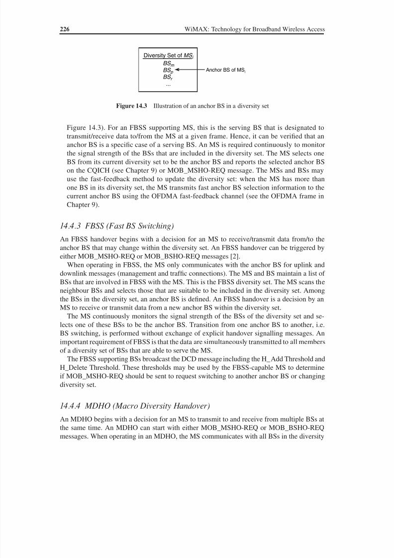
8/10/2019 WiMax-Tech for BBW Access
http://slidepdf.com/reader/full/wimax-tech-for-bbw-access 240/293
226 WiMAX: Technology for Broadband Wireless Access
Figure 14.3). For an FBSS supporting MS, this is the serving BS that is designated to
transmit/receive data to/from the MS at a given frame. Hence, it can be verified that an
anchor BS is a specific case of a serving BS. An MS is required continuously to monitor
the signal strength of the BSs that are included in the diversity set. The MS selects one
BS from its current diversity set to be the anchor BS and reports the selected anchor BS
on the CQICH (see Chapter 9) or MOB_MSHO-REQ message. The MSs and BSs mayuse the fast-feedback method to update the diversity set: when the MS has more than
one BS in its diversity set, the MS transmits fast anchor BS selection information to the
current anchor BS using the OFDMA fast-feedback channel (see the OFDMA frame in
Chapter 9).
14.4.3 FBSS (Fast BS Switching)
An FBSS handover begins with a decision for an MS to receive/transmit data from/to the
anchor BS that may change within the diversity set. An FBSS handover can be triggered by
either MOB_MSHO-REQ or MOB_BSHO-REQ messages [2].When operating in FBSS, the MS only communicates with the anchor BS for uplink and
downlink messages (management and traffic connections). The MS and BS maintain a list of
BSs that are involved in FBSS with the MS. This is the FBSS diversity set. The MS scans the
neighbour BSs and selects those that are suitable to be included in the diversity set. Among
the BSs in the diversity set, an anchor BS is defined. An FBSS handover is a decision by an
MS to receive or transmit data from a new anchor BS within the diversity set.
The MS continuously monitors the signal strength of the BSs of the diversity set and se-
lects one of these BSs to be the anchor BS. Transition from one anchor BS to another, i.e.
BS switching, is performed without exchange of explicit handover signalling messages. An
important requirement of FBSS is that the data are simultaneously transmitted to all members
of a diversity set of BSs that are able to serve the MS.
The FBSS supporting BSs broadcast the DCD message including the H_Add Threshold and
H_Delete Threshold. These thresholds may be used by the FBSS-capable MS to determine
if MOB_MSHO-REQ should be sent to request switching to another anchor BS or changing
diversity set.
14.4.4 MDHO (Macro Diversity Handover)
An MDHO begins with a decision for an MS to transmit to and receive from multiple BSs at
the same time. An MDHO can start with either MOB_MSHO-REQ or MOB_BSHO-REQ
messages. When operating in an MDHO, the MS communicates with all BSs in the diversity
Diversity Set of MS i BS m
BS p BS r
...
Anchor BS of MSi
Figure 14.3 Illustration of an anchor BS in a diversity set
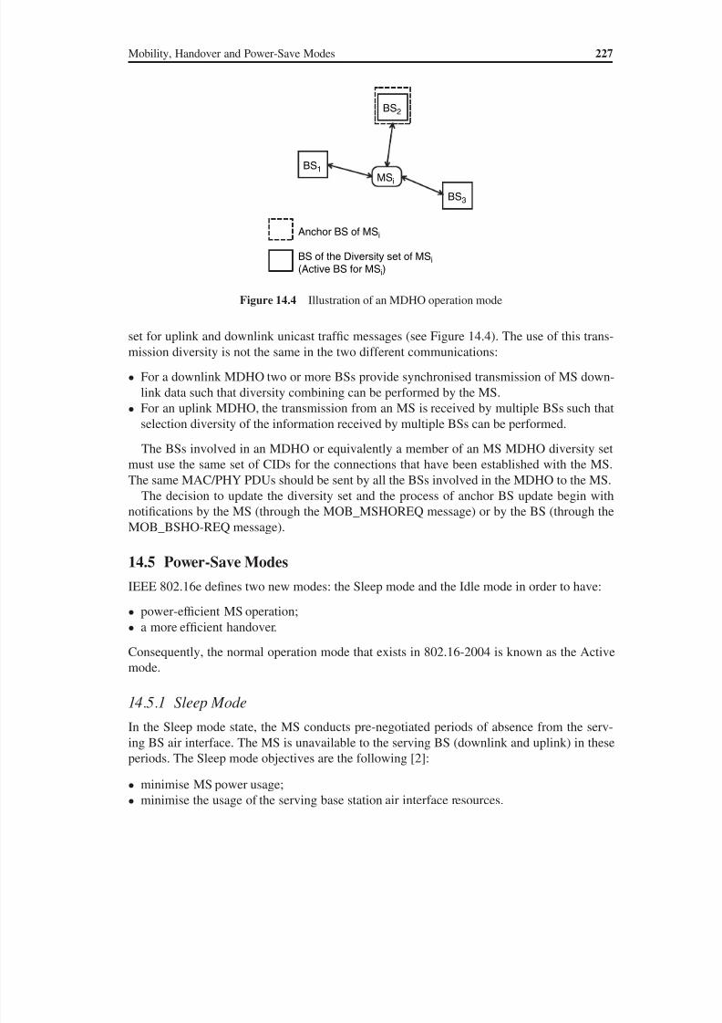
8/10/2019 WiMax-Tech for BBW Access
http://slidepdf.com/reader/full/wimax-tech-for-bbw-access 241/293
Mobility, Handover and Power-Save Modes 227
set for uplink and downlink unicast traffic messages (see Figure 14.4). The use of this trans-
mission diversity is not the same in the two different communications:
• For a downlink MDHO two or more BSs provide synchronised transmission of MS down-
link data such that diversity combining can be performed by the MS.
• For an uplink MDHO, the transmission from an MS is received by multiple BSs such that
selection diversity of the information received by multiple BSs can be performed.
The BSs involved in an MDHO or equivalently a member of an MS MDHO diversity set
must use the same set of CIDs for the connections that have been established with the MS.The same MAC/PHY PDUs should be sent by all the BSs involved in the MDHO to the MS.
The decision to update the diversity set and the process of anchor BS update begin with
notifications by the MS (through the MOB_MSHOREQ message) or by the BS (through the
MOB_BSHO-REQ message).
14.5 Power-Save Modes
IEEE 802.16e defines two new modes: the Sleep mode and the Idle mode in order to have:
• power-efficient MS operation;
• a more efficient handover.
Consequently, the normal operation mode that exists in 802.16-2004 is known as the Active
mode.
14.5.1 Sleep Mode
In the Sleep mode state, the MS conducts pre-negotiated periods of absence from the serv-
ing BS air interface. The MS is unavailable to the serving BS (downlink and uplink) in these
periods. The Sleep mode objectives are the following [2]:
• minimise MS power usage;
• minimise the usage of the serving base station air interface resources.
BS1
BS2
BS3
Anchor BS of MSi
BS of the Diversity set of MSi
(Active BS for MSi)
MSi
Figure 14.4 Illustration of an MDHO operation mode
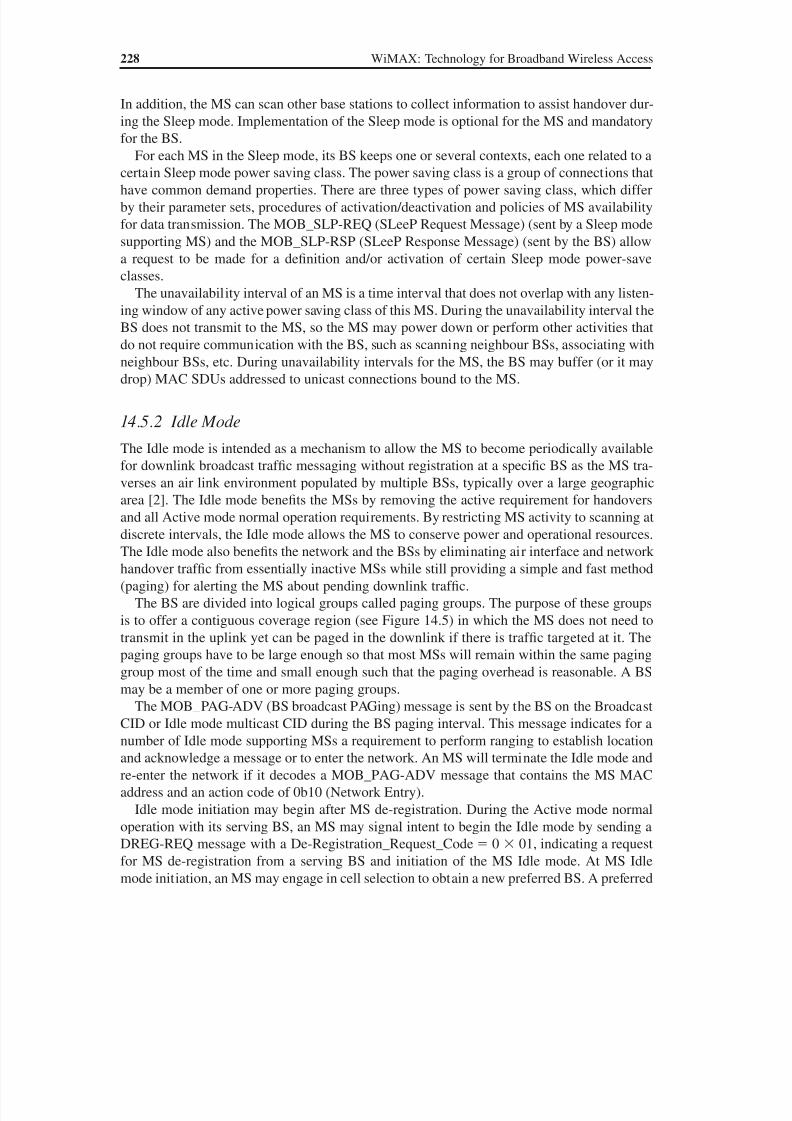
8/10/2019 WiMax-Tech for BBW Access
http://slidepdf.com/reader/full/wimax-tech-for-bbw-access 242/293
228 WiMAX: Technology for Broadband Wireless Access
In addition, the MS can scan other base stations to collect information to assist handover dur-
ing the Sleep mode. Implementation of the Sleep mode is optional for the MS and mandatory
for the BS.
For each MS in the Sleep mode, its BS keeps one or several contexts, each one related to a
certain Sleep mode power saving class. The power saving class is a group of connections thathave common demand properties. There are three types of power saving class, which differ
by their parameter sets, procedures of activation/deactivation and policies of MS availability
for data transmission. The MOB_SLP-REQ (SLeeP Request Message) (sent by a Sleep mode
supporting MS) and the MOB_SLP-RSP (SLeeP Response Message) (sent by the BS) allow
a request to be made for a definition and/or activation of certain Sleep mode power-save
classes.
The unavailability interval of an MS is a time interval that does not overlap with any listen-
ing window of any active power saving class of this MS. During the unavailability interval the
BS does not transmit to the MS, so the MS may power down or perform other activities that
do not require communication with the BS, such as scanning neighbour BSs, associating withneighbour BSs, etc. During unavailability intervals for the MS, the BS may buffer (or it may
drop) MAC SDUs addressed to unicast connections bound to the MS.
14.5.2 Idle Mode
The Idle mode is intended as a mechanism to allow the MS to become periodically available
for downlink broadcast traffic messaging without registration at a specific BS as the MS tra-
verses an air link environment populated by multiple BSs, typically over a large geographic
area [2]. The Idle mode benefits the MSs by removing the active requirement for handovers
and all Active mode normal operation requirements. By restricting MS activity to scanning at
discrete intervals, the Idle mode allows the MS to conserve power and operational resources.
The Idle mode also benefits the network and the BSs by eliminating air interface and network
handover traffic from essentially inactive MSs while still providing a simple and fast method
(paging) for alerting the MS about pending downlink traffic.
The BS are divided into logical groups called paging groups. The purpose of these groups
is to offer a contiguous coverage region (see Figure 14.5) in which the MS does not need to
transmit in the uplink yet can be paged in the downlink if there is traffic targeted at it. The
paging groups have to be large enough so that most MSs will remain within the same paging
group most of the time and small enough such that the paging overhead is reasonable. A BS
may be a member of one or more paging groups.
The MOB_PAG-ADV (BS broadcast PAGing) message is sent by the BS on the Broadcast
CID or Idle mode multicast CID during the BS paging interval. This message indicates for a
number of Idle mode supporting MSs a requirement to perform ranging to establish location
and acknowledge a message or to enter the network. An MS will terminate the Idle mode and
re-enter the network if it decodes a MOB_PAG-ADV message that contains the MS MAC
address and an action code of 0b10 (Network Entry).
Idle mode initiation may begin after MS de-registration. During the Active mode normal
operation with its serving BS, an MS may signal intent to begin the Idle mode by sending a
DREG-REQ message with a De-Registration_Request_Code 0 01, indicating a request
for MS de-registration from a serving BS and initiation of the MS Idle mode. At MS Idle
mode initiation, an MS may engage in cell selection to obtain a new preferred BS. A preferred
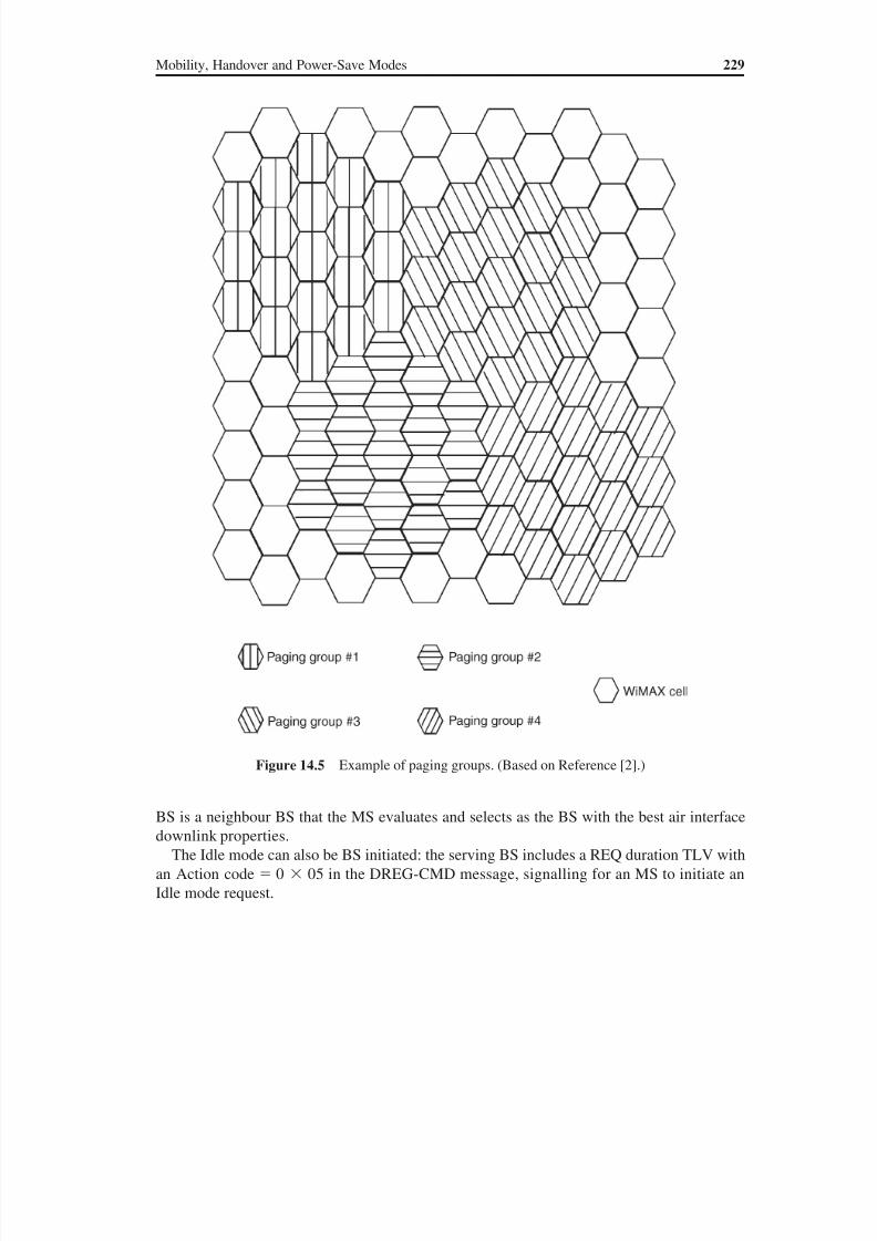
8/10/2019 WiMax-Tech for BBW Access
http://slidepdf.com/reader/full/wimax-tech-for-bbw-access 243/293
Mobility, Handover and Power-Save Modes 229
BS is a neighbour BS that the MS evaluates and selects as the BS with the best air interface
downlink properties.
The Idle mode can also be BS initiated: the serving BS includes a REQ duration TLV with
an Action code 0 05 in the DREG-CMD message, signalling for an MS to initiate an
Idle mode request.
Figure 14.5 Example of paging groups. (Based on Reference [2].)
8/10/2019 WiMax-Tech for BBW Access
http://slidepdf.com/reader/full/wimax-tech-for-bbw-access 244/293
15Security
15.1 Security Elements Used in the 802.16 Standard
A wireless system uses the radio channel, which is an open channel. Hence, securityprocedures must be included in order to protect the traffic confidentiality and integrity and
to prevent different network security attacks such as theft of service. The IEEE 802.16 MAC
layer contains a security sublayer (see the protocol layers in Chapter 3). This sublayer and its
main procedures are described in this chapter.
The Privacy Key Management (PKM) protocol, later known as PKMv1, is included in the
802.16-2004 standard security sublayer in order to provide secure distribution of keying data
from the BS to the SS. In addition, PKM is used to apply conditional access to network ser-
vices, making it the authentication protocol, protecting them from theft of service (or service
hijacking) and providing a secure key exchange. Many ciphering (data encryption) algorithms
are included in the 802.16 standard security sublayer for encrypting packet data across the802.16 network.
The Security sublayer has been redefined in the IEEE 802.16e amendment mainly due to
the fact that 802.16-2004 had some security holes (e.g. no authentication of the BS) and that
the security requirements for mobile services are not the same as for fixed services. The Se-
curity sublayer has two main component protocols as follows:
• A data encapsulation protocol for securing packet data across the fixed BWA network. This
protocol defines a set of supported cryptographic suites, i.e. pairings of data encryption
and authentication algorithms, and the rules for applying those algorithms to a MAC PDU
payload.• A key management protocol (PKM) providing the secure distribution of keying data from
the BS to the SS. Through this key management protocol, the SSs and BSs synchronise
keying data. In addition, the BS uses the protocol to enforce conditional access to network
services. The 802.16e amendment defined PKMv2 with enhanced features.
The Security sublayer of WiMAX as it has been redefined in the IEEE 802.16e is shown
in Figure 15.1. The elements of this figure will be described in this chapter, where an SS is
sometimes denoted MS (as elsewhere in this book).
WiMAX: Technology for Broadband Wireless Access Loutfi Nuaymi
© 2007 John Wiley & Sons, Ltd. ISBN: 0-470-02808-4
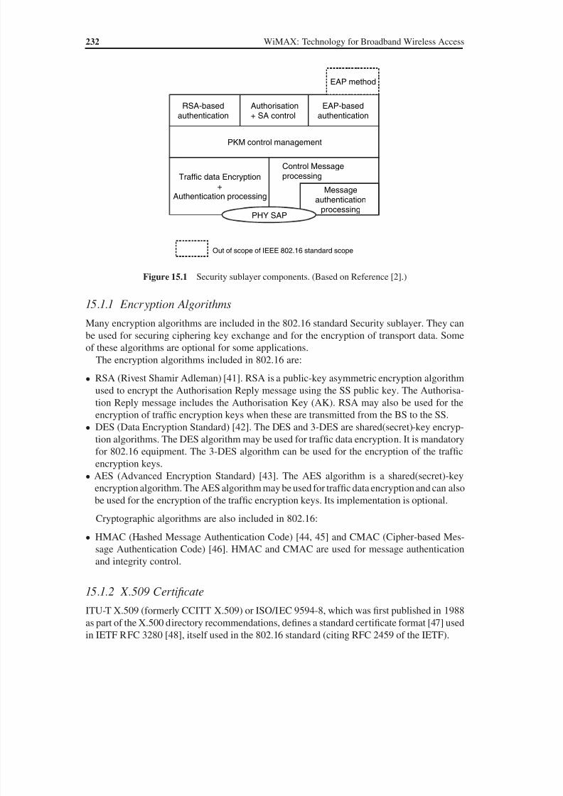
8/10/2019 WiMax-Tech for BBW Access
http://slidepdf.com/reader/full/wimax-tech-for-bbw-access 245/293
232 WiMAX: Technology for Broadband Wireless Access
15.1.1 Encryption Algorithms
Many encryption algorithms are included in the 802.16 standard Security sublayer. They can
be used for securing ciphering key exchange and for the encryption of transport data. Some
of these algorithms are optional for some applications.
The encryption algorithms included in 802.16 are:
• RSA (Rivest Shamir Adleman) [41]. RSA is a public-key asymmetric encryption algorithm
used to encrypt the Authorisation Reply message using the SS public key. The Authorisa-
tion Reply message includes the Authorisation Key (AK). RSA may also be used for the
encryption of traffic encryption keys when these are transmitted from the BS to the SS.
• DES (Data Encryption Standard) [42]. The DES and 3-DES are shared(secret)-key encryp-
tion algorithms. The DES algorithm may be used for traffic data encryption. It is mandatory
for 802.16 equipment. The 3-DES algorithm can be used for the encryption of the traffic
encryption keys.
• AES (Advanced Encryption Standard) [43]. The AES algorithm is a shared(secret)-key
encryption algorithm. The AES algorithm may be used for traffic data encryption and can also
be used for the encryption of the traffic encryption keys. Its implementation is optional.
Cryptographic algorithms are also included in 802.16:
• HMAC (Hashed Message Authentication Code) [44, 45] and CMAC (Cipher-based Mes-
sage Authentication Code) [46]. HMAC and CMAC are used for message authentication
and integrity control.
15.1.2 X.509 Certificate
ITU-T X.509 (formerly CCITT X.509) or ISO/IEC 9594-8, which was first published in 1988
as part of the X.500 directory recommendations, defines a standard certificate format [47] used
in IETF RFC 3280 [48], itself used in the 802.16 standard (citing RFC 2459 of the IETF).
Control MessageprocessingTraffic data Encryption
+Authentication processing
Messageauthentication
processingPHY SAP
PKM control management
RSA-basedauthentication
EAP-basedauthentication
Authorisation+ SA control
EAP method
Out of scope of IEEE 802.16 standard scope
Figure 15.1 Security sublayer components. (Based on Reference [2].)
8/10/2019 WiMax-Tech for BBW Access
http://slidepdf.com/reader/full/wimax-tech-for-bbw-access 246/293
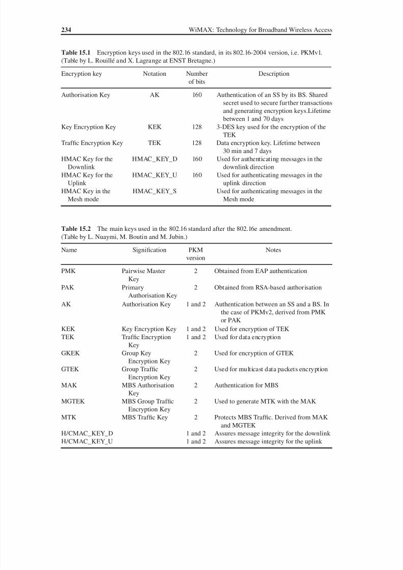
8/10/2019 WiMax-Tech for BBW Access
http://slidepdf.com/reader/full/wimax-tech-for-bbw-access 247/293
234 WiMAX: Technology for Broadband Wireless Access
Table 15.1 Encryption keys used in the 802.16 standard, in its 802.16-2004 version, i.e. PKMv1.
(Table by L. Rouillé and X. Lagrange at ENST Bretagne.)
Encryption key Notation Number
of bits
Description
Authorisation Key AK 160 Authentication of an SS by its BS. Shared
secret used to secure further transactions
and generating encryption keys.Lifetime
between 1 and 70 days
Key Encryption Key KEK 128 3-DES key used for the encryption of the
TEK
Traffic Encryption Key TEK 128 Data encryption key. Lifetime between
30 min and 7 days
HMAC Key for the
Downlink
HMAC_KEY_D 160 Used for authenticating messages in the
downlink direction
HMAC Key for theUplink
HMAC_KEY_U 160 Used for authenticating messages in theuplink direction
HMAC Key in the
Mesh mode
HMAC_KEY_S Used for authenticating messages in the
Mesh mode
Table 15.2 The main keys used in the 802.16 standard after the 802.16e amendment.
(Table by L. Nuaymi, M. Boutin and M. Jubin.)
Name Signification PKM
version
Notes
PMK Pairwise Master
Key
2 Obtained from EAP authentication
PAK Primary
Authorisation Key
2 Obtained from RSA-based authorisation
AK Authorisation Key 1 and 2 Authentication between an SS and a BS. In
the case of PKMv2, derived from PMK
or PAK
KEK Key Encryption Key 1 and 2 Used for encryption of TEK
TEK Traffic Encryption
Key
1 and 2 Used for data encryption
GKEK Group Key
Encryption Key
2 Used for encryption of GTEK
GTEK Group Traffic
Encryption Key
2 Used for multicast data packets encryption
MAK MBS Authorisation
Key
2 Authentication for MBS
MGTEK MBS Group Traffic
Encryption Key
2 Used to generate MTK with the MAK
MTK MBS Traffic Key 2 Protects MBS Traffic. Derived from MAK
and MGTEK
H/CMAC_KEY_D 1 and 2 Assures message integrity for the downlink H/CMAC_KEY_U 1 and 2 Assures message integrity for the uplink
8/10/2019 WiMax-Tech for BBW Access
http://slidepdf.com/reader/full/wimax-tech-for-bbw-access 248/293
Security 235
SA’s shared information includes the Cryptographic Suite employed within the SA. A Cryp-
tographic Suite is the SA’s set of methods for data encryption, data authentication and TEK
exchange. The exact content of the SA is dependent on the SA’s Cryptographic Suite: encyp-
tion keys, keys lifetime, etc. The Security Association Identifier (SAID) is a 16-bit identifier
shared between the BS and the SS that uniquely identifies an SA. There are three types of se-curity associations: the SA for unicast connections, the Group Security Association (GSA) for
multicast groups and the MBS Group Security Association (MBSGSA) for MBS services.
The SAs are managed by the BS. When an authentication event takes place the BS gives
the SS a list of Security Associations associated with its connections. Generally, an SS has a
Security Association (‘primary’ association) for its secondary management connection and
two more for the downlink and the uplink links. After that, the BS may indicate one or more
new SAs to the SS.
Static SAs are provisioned within the BS. Dynamic SAs are created and deleted as required
in response to the initiation and termination of specific service flows.
15.2 Authentication and the PKM Protocol
The security sublayer of IEEE 802.16 employs an authenticated client/server key manage-
ment protocol in which the BS, the server, controls the distribution of keying material to the
client SS. Security is then based on the PKM (Privacy Key Management) protocol [50]. The
BS authenticates a client SS during the initial authorisation exchange (see Chapter 11) using
digital-certificate-based SS authentication. The PKM protocol uses public key cryptography
to establish a shared secret between the SS and the BS. The SS also uses the PKM protocol
to support periodic reauthorisation and key refresh.
If during capabilities negotiation (see Section 11.6 for SBC, SS Basic Capability messagesexchange) the SS specifies that it does not support IEEE 802.16 security, the authorisation
and key exchange procedures in Network Entry process are skipped, i.e. neither key exchange
nor data encryption is performed. The standard states that the BS, if provisioned in this way,
considers the SS authenticated; otherwise, the SS is not serviced.
The 802.16e amendment defined PKMv2 with enhanced features. Table 15.3 summarises
the main differences between the two PKM versions.
First 802.16 PKM protocol MAC management messages are described, followed by the use
of these messages and X.509 digital certificates for authentication and key material exchange.
15.2.1 PKM Protocol MAC Management Messages
The PKM protocol has two generic MAC management messages in the 802.16 standard:
• PKM Request (PKM-REQ). The PKM-REQ message encapsulates one PKM message in
its message payload. It is always sent from the SS to the BS.
• PKM Response (PKM-RSP). The PKM-RSP message encapsulates one PKM message in
its message payload. It is always sent from the BS to the SS.
Both PKM-REQ and PKM-RSP use the primary management connection with the exception
that when the BS sends the PKM-RSP message to the SSs for a multicast service or a broad-
cast service, it may be carried on the broadcast connection. The general formats of PKM-
REQ and PKM-RSP messages are shown in Figures 15.2 and 15.3.

8/10/2019 WiMax-Tech for BBW Access
http://slidepdf.com/reader/full/wimax-tech-for-bbw-access 249/293
236 WiMAX: Technology for Broadband Wireless Access
Table 15.4 is a synthesis of 802.16 standard PKMv1 MAC management messages param-
eters and descriptions. The PKM-REQ and PKM-RSP messages codes added for PKMv2 can
be found in Table 26 of Reference [2].
15.2.2 PKMv1: the BS Authenticates the SS and then Provides it with Keying
Material
After capability negotiation, the BS authenticates the SS and provides it with key material
to enable the ciphering of data. All SSs have factory-installed RSA private/public key pairsor provide an internal algorithm to generate such key pairs dynamically. The SSs with fac-
tory-installed RSA key pairs also have factory-installed X.509 certificates. The SSs that rely
on internal algorithms to generate an RSA key pair support a mechanism for installing a
manufacturer-issued X.509 certificate following key generation.
Thus, each SS has a unique X.509 digital certificate issued by the SS manufacturer [1].
The SS X.509 digital certificate contains the SS public key and the SS MAC address. The
Table 15.3 The main differences between PKMv1 and PKMv2. (Table by L. Nuaymi, M. Boutin
and M. Jubin.)
Feature PKMv1 PKMv2
Authentication RSA-based one-way authentication:the BS authenticates the SS
Mutual authentication. Supports twoauthentication methods: EAP or
RSA
Security Association One SA family: Unicast.Composed
of three types of security
associations: primary, dynamic
and static
Three SA families: Unicast, Group
Security Association and MBS
Security Association.Composed
of the same three types of security
associations as PKMv1
Key encryption Use of three encryption algorithms:
3-DES, RSA and AES
New encryption method
implemented: AES with Key Wrap
Data encryption Two different algorithms are
defined in the standard:
• DES in the CBC mode,
• AES in the CCM mode
Use of the same algorithms plus AES
in the CTR mode and AES in the
CBC mode implementation
Other additions — Management of security for:
• broadcast traffic,
• MBS traffic.
Definition of a preauthentication
procedure in the case of handover
Management Message Type
(=9, for PKM-REQ)
Code
(8 bits)
PKM Identifier
(8 bits)
TLV Encoded
Information
Figure 15.2 PKM-REQ MAC management message format
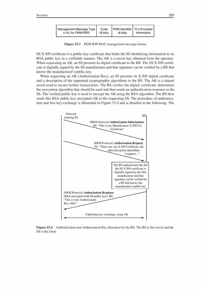
8/10/2019 WiMax-Tech for BBW Access
http://slidepdf.com/reader/full/wimax-tech-for-bbw-access 250/293
Security 237
SS X.509 certificate is a public key certificate that binds the SS identifying information to its
RSA public key in a verifiable manner. The AK is a secret key obtained from the operator.
When requesting an AK, an SS presents its digital certificate to the BS. The SS X.509 certifi-
cate is digitally signed by the SS manufacturer and that signature can be verified by a BS that
knows the manufacturer’s public key.
When requesting an AK (Authorisation Key), an SS presents its X.509 digital certificate
and a description of the supported cryptographic algorithms to the BS. The AK is a shared
secret used to secure further transactions. The BS verifies the digital certificate, determines
the encryption algorithm that should be used and then sends an authentication response to the
SS. The verified public key is used to encrypt the AK using the RSA algorithm. The BS then
sends this RSA public key encrypted AK to the requesting SS. The procedure of authentica-
tion and first key exchange is illustrated in Figure 15.4 and is detailed in the following. The
Management Message Type(=10, for PKM-RSP)
Code(8 bits)
PKM Identifier(8 bits)
TLV EncodedInformation
Figure 15.3 PKM-RSP MAC management message format
(PKM Protocol) Authorisation Request;SS: “These are: my X.509 Certificate, the
data encryption algorithms I support,...”
BSNetwork
entering SS
(PKM Protocol) Authorisation Information;SS: “This is my Manufacturer X.509 CA
Certificate”
The BS authenticates the SS:the SS X.509 certificate isdigitally signed by the SS's
manufacturer and thatsignature can be verified by
a BS that knows themanufacturer's public key
(PKM Protocol) Authorisation Response (RSA-encrypted with SS public key); BS:“This is your AuthorisationKey (AK)”
Ciphering keys exchange, using AK
Figure 15.4 Authentication and Authorisation Key allocation by the BS. The BS is the server and theSS is the client
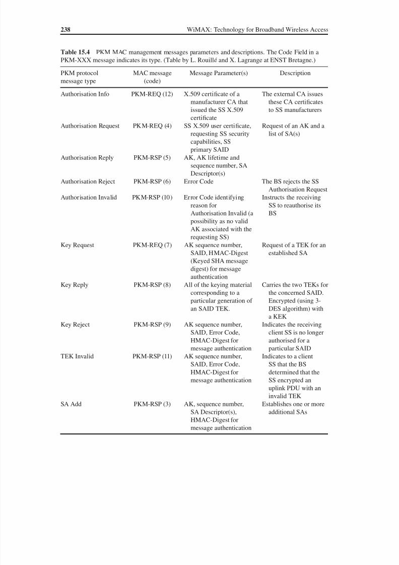
8/10/2019 WiMax-Tech for BBW Access
http://slidepdf.com/reader/full/wimax-tech-for-bbw-access 251/293
238 WiMAX: Technology for Broadband Wireless Access
Table 15.4 PKM MAC management messages parameters and descriptions. The Code Field in aPKM-XXX message indicates its type. (Table by L. Rouillé and X. Lagrange at ENST Bretagne.)
PKM protocolmessage type
MAC message(code)
Message Parameter(s) Description
Authorisation Info PKM-REQ (12) X.509 certificate of amanufacturer CA thatissued the SS X.509certificate
The external CA issuesthese CA certificatesto SS manufacturers
Authorisation Request PKM-REQ (4) SS X.509 user certificate,requesting SS securitycapabilities, SSprimary SAID
Request of an AK and alist of SA(s)
Authorisation Reply PKM-RSP (5) AK, AK lifetime andsequence number, SA
Descriptor(s)Authorisation Reject PKM-RSP (6) Error Code The BS rejects the SS
Authorisation RequestAuthorisation Invalid PKM-RSP (10) Error Code identifying
reason forAuthorisation Invalid (apossibility as no validAK associated with therequesting SS)
Instructs the receivingSS to reauthorise itsBS
Key Request PKM-REQ (7) AK sequence number,SAID, HMAC-Digest(Keyed SHA messagedigest) for messageauthentication
Request of a TEK for anestablished SA
Key Reply PKM-RSP (8) All of the keying materialcorresponding to aparticular generation ofan SAID TEK.
Carries the two TEKs forthe concerned SAID.Encrypted (using 3-DES algorithm) witha KEK
Key Reject PKM-RSP (9) AK sequence number,SAID, Error Code,
HMAC-Digest formessage authentication
Indicates the receivingclient SS is no longer
authorised for aparticular SAIDTEK Invalid PKM-RSP (11) AK sequence number,
SAID, Error Code,HMAC-Digest formessage authentication
Indicates to a clientSS that the BSdetermined that theSS encrypted anuplink PDU with aninvalid TEK
SA Add PKM-RSP (3) AK, sequence number,SA Descriptor(s),HMAC-Digest for
message authentication
Establishes one or moreadditional SAs
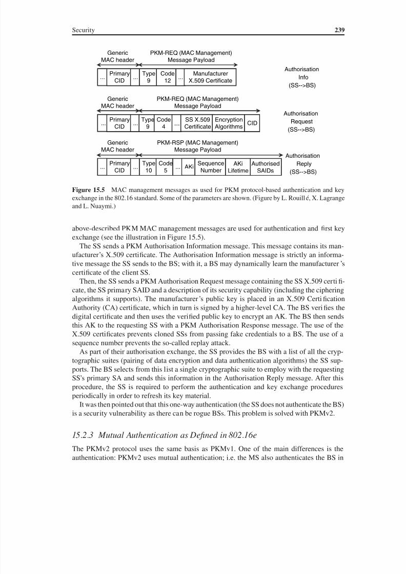
8/10/2019 WiMax-Tech for BBW Access
http://slidepdf.com/reader/full/wimax-tech-for-bbw-access 252/293
Security 239
above-described PKM MAC management messages are used for authentication and first keyexchange (see the illustration in Figure 15.5).
The SS sends a PKM Authorisation Information message. This message contains its man-ufacturer’s X.509 certificate. The Authorisation Information message is strictly an informa-
tive message the SS sends to the BS; with it, a BS may dynamically learn the manufacturer’scertificate of the client SS.
Then, the SS sends a PKM Authorisation Request message containing the SS X.509 certifi-cate, the SS primary SAID and a description of its security capability (including the cipheringalgorithms it supports). The manufacturer’s public key is placed in an X.509 CertificationAuthority (CA) certificate, which in turn is signed by a higher-level CA. The BS verifies thedigital certificate and then uses the verified public key to encrypt an AK. The BS then sendsthis AK to the requesting SS with a PKM Authorisation Response message. The use of theX.509 certificates prevents cloned SSs from passing fake credentials to a BS. The use of asequence number prevents the so-called replay attack.
As part of their authorisation exchange, the SS provides the BS with a list of all the cryp-tographic suites (pairing of data encryption and data authentication algorithms) the SS sup-ports. The BS selects from this list a single cryptographic suite to employ with the requestingSS’s primary SA and sends this information in the Authorisation Reply message. After thisprocedure, the SS is required to perform the authentication and key exchange proceduresperiodically in order to refresh its key material.
It was then pointed out that this one-way authentication (the SS does not authenticate the BS)is a security vulnerability as there can be rogue BSs. This problem is solved with PKMv2.
15.2.3 Mutual Authentication as Defined in 802.16eThe PKMv2 protocol uses the same basis as PKMv1. One of the main differences is theauthentication: PKMv2 uses mutual authentication; i.e. the MS also authenticates the BS in
...
GenericMAC header
PrimaryCID
...Type
9Code
12...
ManufacturerX.509 Certificate
PKM-REQ (MAC Management)Message Payload
...
GenericMAC header
PrimaryCID
...Type
9Code
4...
SS X.509Certificate
PKM-REQ (MAC Management)Message Payload
EncryptionAlgorithms
CID
...
GenericMAC header
PrimaryCID
...Type10
Code5
... AKi
PKM-RSP (MAC Management)Message Payload
SequenceNumber
AuthorisedSAIDs
AKiLifetime
Authorisation
Info
(SS-->BS)
Authorisation
Request
(SS-->BS)
Authorisation
Reply
(SS-->BS)
Figure 15.5 MAC management messages as used for PKM protocol-based authentication and keyexchange in the 802.16 standard. Some of the parameters are shown. (Figure by L. Rouillé, X. Lagrangeand L. Nuaymi.)
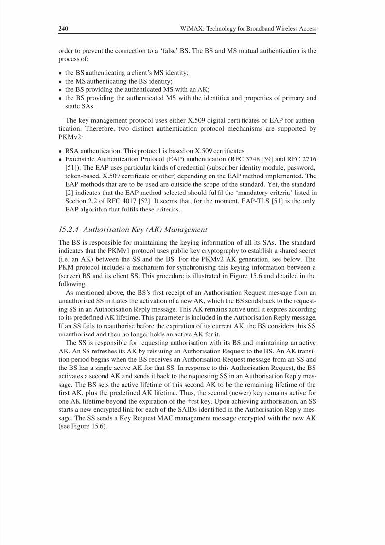
8/10/2019 WiMax-Tech for BBW Access
http://slidepdf.com/reader/full/wimax-tech-for-bbw-access 253/293
240 WiMAX: Technology for Broadband Wireless Access
order to prevent the connection to a ‘false’ BS. The BS and MS mutual authentication is theprocess of:
• the BS authenticating a client’s MS identity;
• the MS authenticating the BS identity;• the BS providing the authenticated MS with an AK;
• the BS providing the authenticated MS with the identities and properties of primary andstatic SAs.
The key management protocol uses either X.509 digital certificates or EAP for authen-tication. Therefore, two distinct authentication protocol mechanisms are supported byPKMv2:
• RSA authentication. This protocol is based on X.509 certificates.
• Extensible Authentication Protocol (EAP) authentication (RFC 3748 [39] and RFC 2716
[51]). The EAP uses particular kinds of credential (subscriber identity module, password,token-based, X.509 certificate or other) depending on the EAP method implemented. TheEAP methods that are to be used are outside the scope of the standard. Yet, the standard[2] indicates that the EAP method selected should fulfil the ‘mandatory criteria’ listed inSection 2.2 of RFC 4017 [52]. It seems that, for the moment, EAP-TLS [51] is the onlyEAP algorithm that fulfils these criterias.
15.2.4 Authorisation Key (AK) Management
The BS is responsible for maintaining the keying information of all its SAs. The standard
indicates that the PKMv1 protocol uses public key cryptography to establish a shared secret(i.e. an AK) between the SS and the BS. For the PKMv2 AK generation, see below. ThePKM protocol includes a mechanism for synchronising this keying information between a(server) BS and its client SS. This procedure is illustrated in Figure 15.6 and detailed in thefollowing.
As mentioned above, the BS’s first receipt of an Authorisation Request message from anunauthorised SS initiates the activation of a new AK, which the BS sends back to the request-ing SS in an Authorisation Reply message. This AK remains active until it expires accordingto its predefined AK lifetime. This parameter is included in the Authorisation Reply message.If an SS fails to reauthorise before the expiration of its current AK, the BS considers this SSunauthorised and then no longer holds an active AK for it.
The SS is responsible for requesting authorisation with its BS and maintaining an activeAK. An SS refreshes its AK by reissuing an Authorisation Request to the BS. An AK transi-tion period begins when the BS receives an Authorisation Request message from an SS andthe BS has a single active AK for that SS. In response to this Authorisation Request, the BSactivates a second AK and sends it back to the requesting SS in an Authorisation Reply mes-sage. The BS sets the active lifetime of this second AK to be the remaining lifetime of thefirst AK, plus the predefined AK lifetime. Thus, the second (newer) key remains active forone AK lifetime beyond the expiration of the first key. Upon achieving authorisation, an SSstarts a new encrypted link for each of the SAIDs identified in the Authorisation Reply mes-sage. The SS sends a Key Request MAC management message encrypted with the new AK(see Figure 15.6).
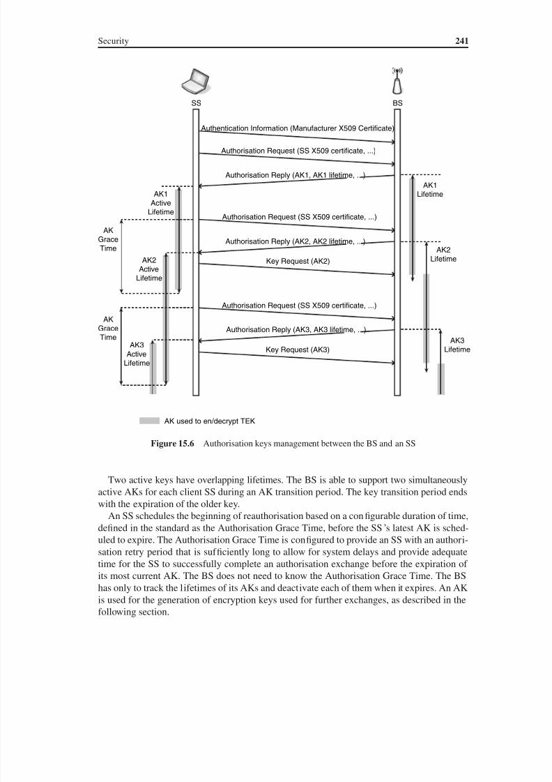
8/10/2019 WiMax-Tech for BBW Access
http://slidepdf.com/reader/full/wimax-tech-for-bbw-access 254/293
Security 241
Two active keys have overlapping lifetimes. The BS is able to support two simultaneouslyactive AKs for each client SS during an AK transition period. The key transition period endswith the expiration of the older key.
An SS schedules the beginning of reauthorisation based on a configurable duration of time,defined in the standard as the Authorisation Grace Time, before the SS’s latest AK is sched-uled to expire. The Authorisation Grace Time is configured to provide an SS with an authori-sation retry period that is suf ficiently long to allow for system delays and provide adequatetime for the SS to successfully complete an authorisation exchange before the expiration ofits most current AK. The BS does not need to know the Authorisation Grace Time. The BShas only to track the lifetimes of its AKs and deactivate each of them when it expires. An AKis used for the generation of encryption keys used for further exchanges, as described in thefollowing section.
AK
GraceTime
AK
Grace
Time
AK2
Active
Lifetime
AK3
ActiveLifetime
AK used to en/decrypt TEK
Key Request (AK3)
Key Request (AK2)
Authorisation Reply (AK3, AK3 lifetime, ...)
Authorisation Reply (AK2, AK2 lifetime, ...)
Authorisation Reply (AK1, AK1 lifetime, ...)
Authentication Information (Manufacturer X509 Certificate)
Authorisation Request (SS X509 certificate, ...)
Authorisation Request (SS X509 certificate, ...)
Authorisation Request (SS X509 certificate, ...)
AK1
Active
Lifetime
AK1
Lifetime
AK2
Lifetime
AK3
Lifetime
BSSS
Figure 15.6 Authorisation keys management between the BS and an SS
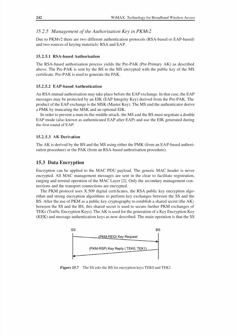
8/10/2019 WiMax-Tech for BBW Access
http://slidepdf.com/reader/full/wimax-tech-for-bbw-access 255/293
242 WiMAX: Technology for Broadband Wireless Access
15.2.5 Management of the Authorisation Key in PKMv2
Due to PKMv2 there are two different authentication protocols (RSA-based or EAP-based)and two sources of keying materials: RSA and EAP.
15.2.5.1 RSA-based Authorisation
The RSA-based authorisation process yields the Pre-PAK (Pre-Primary AK) as describedabove. The Pre-PAK is sent by the BS to the MS encrypted with the public key of the MScertificate. Pre-PAK is used to generate the PAK.
15.2.5.2 EAP-based Authentication
An RSA mutual authorisation may take place before the EAP exchange. In that case, the EAPmessages may be protected by an EIK (EAP Integrity Key) derived from the Pre-PAK. Theproduct of the EAP exchange is the MSK (Master Key). The MS and the authenticator derivea PMK by truncating the MSK and an optional EIK.
In order to prevent a man-in-the-middle attack, the MS and the BS must negotiate a doubleEAP mode (also known as authenticated EAP after EAP) and use the EIK generated duringthe first round of EAP.
15.2.5.3 AK Derivation
The AK is derived by the BS and the MS using either the PMK (from an EAP-based authori-sation procedure) or the PAK (from an RSA-based authorisation procedure).
15.3 Data Encryption
Encryption can be applied to the MAC PDU payload. The generic MAC header is neverencrypted. All MAC management messages are sent in the clear to facilitate registration,ranging and normal operation of the MAC Layer [2]. Only the secondary management con-nections and the transport connections are encrypted.
The PKM protocol uses X.509 digital certificates, the RSA public key encryption algo-rithm and strong encryption algorithms to perform key exchanges between the SS and theBS. After the use of PKM as a public key cryptography to establish a shared secret (the AK)between the SS and the BS, this shared secret is used to secure further PKM exchanges ofTEKs (Traf fic Encryption Keys). The AK is used for the generation of a Key Encryption Key(KEK) and message authentication keys as now described. The main operation is that the SS
BSSS
(PKM-REQ) Key Request
(PKM-RSP) Key Reply ( TEK0, TEK1)
Figure 15.7 The SS asks the BS for encryption keys TEK0 and TEK1
8/10/2019 WiMax-Tech for BBW Access
http://slidepdf.com/reader/full/wimax-tech-for-bbw-access 256/293
Security 243
asks the BS for encryption keys (see Figure 15.7). The use of the shared secret, AK, for atwo-tiered mechanism for key distribution (described in the following section) permits TEKsto be refreshed without incurring the overhead of computation intensive operations.
15.3.1 Generation of Encryption Keys
At each instant, the BS maintains two sets of active generations of keying material per SA(or, equivalently, per SAID). A set of keying material includes a TEK and its correspondinginitialisation vectors (depending of the encryption algorithm). As for the AK, one set cor-responds to the older generation of keying material while the second set corresponds to thenewer generation of keying material. The BS distributes both generations of active keyingmaterial to a client SS. This is done after the SS has requested a TEK with a Key Requestmessage. The Key Reply message contains two TEK parameter attributes, each containingthe keying material for one of the SAID’s two active sets of keying material.
The BS uses the two active TEKs differently, depending on whether the TEK is used fordownlink or uplink traf fic. For each of its SAIDs, the BS uses the two active TEKs accordingto the following rules (illustrated in Figure 15.8):
1. The BS uses the older of the two active TEKs for encrypting downlink traf fic.2. The BS decrypts the uplink traf fic using either the older or newer TEK, depending on
which of the two keys the SS uses at the time.
Figure 15.9 illustrates the BS management of an SA TEK, where the shaded portion of aTEK’s lifetime indicates the time period during which that TEK is used to encrypt MAC PDUpayloads. As for AKs, TEKs have a limited lifetime and must be periodically refreshed. At ex-
piration of the older TEK, the BS uses the newer TEK for encryption. It is the responsibility ofthe SS to update its keys in a timely fashion. The BS uses a KEK when encrypting the TEK inthe Key Reply (PKM-RSP) MAC management message. The TEK is encrypted with one of thefollowing algorithms, using the KEK: 3-DES, RSA or AES. The TEK encryption algorithm isindicated by the TEK encryption algorithm identifier in the cryptographic suite of the SA.
A random or pseudo-random number generator is used by the BS to generate KEKs andTEKs. The standard [1] states that recommended practices for generating random numbers foruse within cryptographic systems are provided in IETF RFC 1750 [53]. As a remark, it shouldbe pointed out that IETF RFC 1750 has been replaced (by the IETF) by IETF RFC 4086 [54].For the 3-DES KEK, the 802.16 standard defines the following method [1]:
K_PAD_KEK 0 53 repeated 64 times, i.e. a 512-bit string, KEK Truncate(SHA(K_PAD_KEK | AK),128),
whereTruncate ( x ,n) denotes the result of truncating x to its leftmost n bits,
Uplink, TEK1 or TEK2BSSS
Downlink, TEK1
Figure 15.8 Traf fic Encryption Keys (TEKs) management. (From IEEE Std 802.16-2004 [1]. Copy-right IEEE 2004, IEEE. All rights reserved.)
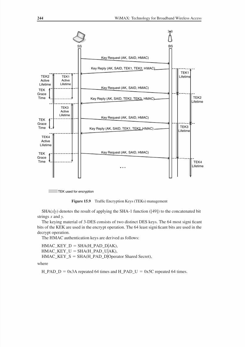
8/10/2019 WiMax-Tech for BBW Access
http://slidepdf.com/reader/full/wimax-tech-for-bbw-access 257/293
244 WiMAX: Technology for Broadband Wireless Access
SHA( x | y) denotes the result of applying the SHA-1 function ([49]) to the concatenated bitstrings x and y.
The keying material of 3-DES consists of two distinct DES keys. The 64 most significantbits of the KEK are used in the encrypt operation. The 64 least significant bits are used in thedecrypt operation.
The HMAC authentication keys are derived as follows:
HMAC_KEY_D SHA(H_PAD_D|AK), HMAC_KEY_U SHA(H_PAD_U|AK), HMAC_KEY_S SHA(H_PAD_D|Operator Shared Secret),
where
H_PAD_D 0x3A repeated 64 times and H_PAD_U 0x5C repeated 64 times.
TEK
Grace
Time
TEK
Grace
Time
TEK
GraceTime
TEK4
Active
Lifetime
TEK used for encryption
Key Request (AK, SAID, HMAC)
Key Request (AK, SAID, HMAC)
Key Request (AK, SAID, HMAC)
Key Request (AK, SAID, HMAC)
Key Reply (AK, SAID, TEK1, TEK2, HMAC)
Key Reply (AK, SAID, TEK2, TEK3, HMAC)
Key Reply (AK, SAID, TEK1, TEK2, HMAC)
TEK1Active
Lifetime
TEK3
Active
Lifetime
TEK2
Active
Lifetime
TEK4
Lifetime
TEK3
Lifetime
TEK2
Lifetime
TEK1
Lifetime
BSSS
Figure 15.9 Traf fic Encryption Keys (TEKs) management

8/10/2019 WiMax-Tech for BBW Access
http://slidepdf.com/reader/full/wimax-tech-for-bbw-access 258/293
Security 245
The exchange of AK and the exchange of Traf fic Encryption Keys (TEKs) takes place foreach SA.
The Operator Shared Secret is a Mesh mode key known by all Mesh mode nodes.
15.3.2 Generation of Encryption Keys in the 802.16e Amendment
As for PKMv1, the PKMv2 protocol uses the TEK and KEK for the encryption of data flows.The KEK is used to encrypt the TEK, GKEK and all other keys sent by the BS to the SS ina unicast message.
15.3.2.1 TEK and KEK
The procedure is the same as for PKMv1 (see the previous section).
15.3.2.2 Multicast Encryption
There is one GKEK per Group Security Association. This GKEK is used to encrypt theGTEKs sent in multicast messages by the BS to the MSs in the same multicast group. It isused to encrypt multicast data packets and it is shared by all the MSs in the multicast group.The GKEK is randomly generated by the BS and encrypted using the same algorithms ap-plied for TEK encryption.
15.3.2.3 Multicast and Broadcast Service Traffic Key
Like the other traf fic keys, the MTK is used to encrypt the MBS traf fic data. The MGTEK isthe GTEK for the MBS. The key generation process in PKMv1 and PKMv2 is summarisedin Figure 15.10.
Control
Data
Pre-PAK PAK
AK
KEK
GKEK GTEK
TEK0
TEK1
PKMv2 RSA-Authentication
PMK
PKMv2 EAP-Authentication
HMAC/CMAC
Figure 15.10 Illustration of the key generation process in PKMv1 and PKMv2. (Figure by M. Boutin,M. Jubin and L. Nuaymi.)
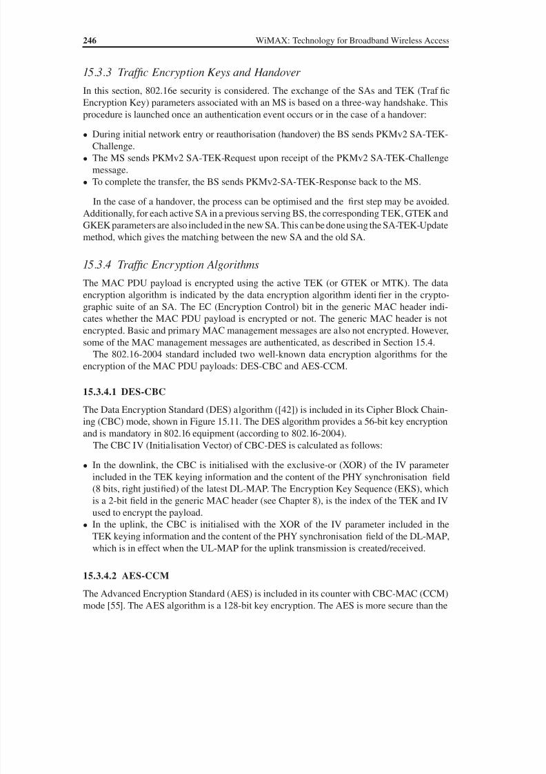
8/10/2019 WiMax-Tech for BBW Access
http://slidepdf.com/reader/full/wimax-tech-for-bbw-access 259/293
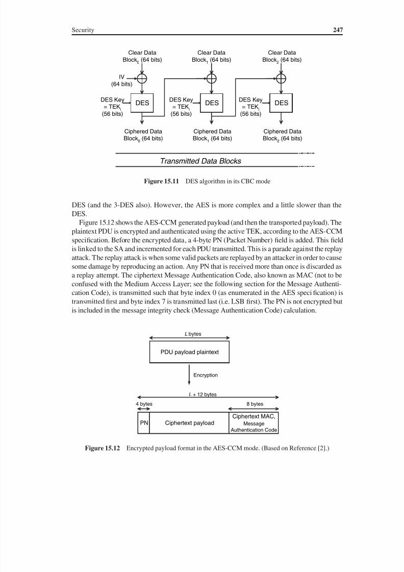
8/10/2019 WiMax-Tech for BBW Access
http://slidepdf.com/reader/full/wimax-tech-for-bbw-access 260/293
Security 247
DES (and the 3-DES also). However, the AES is more complex and a little slower than theDES.
Figure 15.12 shows the AES-CCM generated payload (and then the transported payload). Theplaintext PDU is encrypted and authenticated using the active TEK, according to the AES-CCMspecification. Before the encrypted data, a 4-byte PN (Packet Number) field is added. This fieldis linked to the SA and incremented for each PDU transmitted. This is a parade against the replay
attack. The replay attack is when some valid packets are replayed by an attacker in order to causesome damage by reproducing an action. Any PN that is received more than once is discarded asa replay attempt. The ciphertext Message Authentication Code, also known as MAC (not to beconfused with the Medium Access Layer; see the following section for the Message Authenti-cation Code), is transmitted such that byte index 0 (as enumerated in the AES specification) istransmitted first and byte index 7 is transmitted last (i.e. LSB first). The PN is not encrypted butis included in the message integrity check (Message Authentication Code) calculation.
DES
Clear DataBlock
0 (64 bits)
IV
(64 bits)
DES
Clear DataBlock
1 (64 bits)
DES Key= TEK
i
(56 bits)
DES Key= TEK
i
(56 bits)
DES
Clear DataBlock
2 (64 bits)
DES Key= TEK
i
(56 bits)
Transmitted Data Blocks
Ciphered DataBlock
0 (64 bits)
Ciphered DataBlock
1 (64 bits)
Ciphered DataBlock
2 (64 bits)
Figure 15.11 DES algorithm in its CBC mode
L bytes
PDU payload plaintext
Encryption
L + 12 bytes
Ciphertext payloadPNCiphertext MAC,
Message
Authentication Code
4 bytes 8 bytes
Figure 15.12 Encrypted payload format in the AES-CCM mode. (Based on Reference [2].)

8/10/2019 WiMax-Tech for BBW Access
http://slidepdf.com/reader/full/wimax-tech-for-bbw-access 261/293
248 WiMAX: Technology for Broadband Wireless Access
15.3.5 Traffic Encryption Algorithms Added in the 802.16e Amendment
The 802.16e amendment added the following encryption algorithms:
• AES in Counter (CTR) mode [56] for MBS;
• AES in CBC mode;
• AES KeyWrap with a 128-bit key. The AES key wrap encryption algorithm accepts botha ciphertext and an integrity check value. The decryption algorithm returns a plaintext keyand the integrity check value.
One or more of the 802.16 defined encryption algorithms can be mandatory in WiMAX profiles.
15.4 Message Authentication with HMAC
The standard states that basic and primary MAC management messages are sent in the clear
in order to facilitate registration, ranging and normal operation of the MAC. Thus, authen-tication and integrity protection of MAC messages is very important. The MAC (MessageAuthentication Code) sequences, known as keyed hash or MAC-Digest, are used to sign man-agement messages in order to validate their authenticity (see Figure 15.13). The MAC tagsare generated and then verified using the same secret key (which is a basic difference witherror-detecting codes such as the parity bits). This means that the sender and the receiver ofthe message must agree on the secret key before starting communications. Evidently, this keyis probably different from the encryption key.
The 802.16 standard security includes the use of a Hashed Message Authentication Code(HMAC) for some message authentication and integrity control. 802.16e added the possibility
of using CMAC as an alternative to HMAC. The HMAC keyed hash (or HMAC-Digest) is in:
• The HMAC-Digest attribute, which is present in some PKM messages such as Key Re-quest, Key Reply, Key Reject, etc.
• The HMAC Tuple is a TLV parameter used for some MAC management message authen-tications. The messages that can be authenticated with HMAC include DSx-REQ, DSx-ACK, REG-REQ, etc. The HMAC Tuple is made of HMAC-Digest HMAC with SHA-1,on 160 bits, HMAC Key Sequence Number, on 4 bits, and a reserved field. The HMAC
Message
Message
AuthenticationCode:
HMAC or CMAC
SecretKey
Encryption
(Hashing)Algorithm
MAC
Figure 15.13 Illustration of HMAC or CMAC generation. The MAC is also called keyed hash or MACDigest
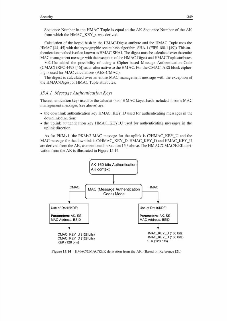
8/10/2019 WiMax-Tech for BBW Access
http://slidepdf.com/reader/full/wimax-tech-for-bbw-access 262/293
Security 249
Sequence Number in the HMAC Tuple is equal to the AK Sequence Number of the AKfrom which the HMAC_KEY_x was derived.
Calculation of the keyed hash in the HMAC-Digest attribute and the HMAC Tuple uses the
HMAC [44, 45] with the cryptographic secure hash algorithm, SHA-1 (FIPS 180-1 [49]). This au-thentication method is often known as HMAC-SHA1. The digest must be calculated over the entireMAC management message with the exception of the HMAC-Digest and HMAC Tuple attributes.
802.16e added the possibility of using a Cipher-based Message Authentication Code(CMAC) (RFC 4493 [46]) as an alternative to the HMAC. For the CMAC, AES block cipher-ing is used for MAC calculations (AES-CMAC).
The digest is calculated over an entire MAC management message with the exception ofthe HMAC-Digest or HMAC Tuple attributes.
15.4.1 Message Authentication Keys
The authentication keys used for the calculation of HMAC keyed hash included in some MACmanagement messages (see above) are:
• the downlink authentication key HMAC_KEY_D used for authenticating messages in thedownlink direction;
• the uplink authentication key HMAC_KEY_U used for authenticating messages in theuplink direction.
As for PKMv1, the PKMv2 MAC message for the uplink is C/HMAC_KEY_U and theMAC message for the downlink is C/HMAC_KEY_D. HMAC_KEY_D and HMAC_KEY_U
are derived from the AK, as mentioned in Section 15.3 above. The HMAC/CMAC/KEK deri-vation from the AK is illustrated in Figure 15.14.
AK-160 bits AuthenticationAK context
MAC (Message Authentication
Code) Mode
Use of Dot16KDF;
Parameters: AK, SSMAC Address, BSID
CMAC_KEY_U (128 bits)CMAC_KEY_D (128 bits)
KEK (128 bits)
Use of Dot16KDF;
Parameters: AK, SSMAC Address, BSID
HMAC_KEY_U (160 bits)HMAC_KEY_D (160 bits)KEK (128 bits)
CMAC HMAC
Figure 15.14 HMAC/CMAC/KEK derivation from the AK. (Based on Reference [2].)
8/10/2019 WiMax-Tech for BBW Access
http://slidepdf.com/reader/full/wimax-tech-for-bbw-access 263/293
250 WiMAX: Technology for Broadband Wireless Access
The BS uses HMAC_KEY_D and HMAC_KEY_U for the following:
• Verify the HMAC-Digest attributes in Key Request MAC management messages receivedfrom that SS, using HMAC_KEY_U.
• Calculate, using HMAC_KEY_D, the HMAC-Digest attributes it writes into Key Reply,Key Reject and TEK Invalid MAC management messages sent to that SS.
• When receiving MAC messages containing the HMAC Tuple attribute, the BS uses the HMAC_KEY_U indicated by the HMAC Key Sequence Number to authenticate the messages.
HMAC_KEY_S is used in the Mesh mode HMAC-Digest calculation.
15.5 Other Security Issues
The procedures seen in this chapter are all about device authentication (SS or BS). Higher-
level protocols, such as the higher-level EAP, may be used for this purpose. This type ofauthentication is part of a WiMAX network specification.

8/10/2019 WiMax-Tech for BBW Access
http://slidepdf.com/reader/full/wimax-tech-for-bbw-access 264/293
16Comparisons and Conclusion
16.1 Comparison Between Fixed WiMAX and Mobile WiMAX
In this chapter, some comparisons and then the conclusion are proposed. It is rather risky togive comparisons in a time where the broadband wireless access is at the eve of great changes
and innovations. However, based on technical background, many news reports and confer-
ence analyses, some comparisons are given. A start is made by comparing Fixed WiMAX
and Mobile WiMAX.
Which technology must be chosen? Fixed WiMAX products are already here. The problem
is that they can only propose a fixed wireless access, although at rather long distances, up to
20 km. Is it better for an operator to wait some time, until the end of 2007 or the beginning
of 2008, according to present expectations, to have Mobile WiMAX? It is up to each opera-
tor to decide, taking into account the market targeted. In places where telecommunication
infrastructure is well developed, it seems that Fixed WiMAX cannot compete with wiredtechnologies such as DSL. Indeed, it would be surprising to have a wireless (unlimited) Mb/s
cheaper than a wired (unlimited) Mb/s in London or Paris one day soon. However, what if
this wireless (unlimited) Mb/s includes nomadicity (‘your PDA Internet connection works
everywhere in the city, although you have to restart your session’) and, even more, mobility
(‘your session is uninterrupted when you move’)?
WiMAX has some strong advantages: the same infrastructure can have Fixed and
Mobile WiMAX access; the operator can start by covering a small area (if regulatory
requirements do not forbid it) in order to adapt the deployment evolution to the busi-
ness case. This is sometimes known as the ‘pay as you grow’ model. More generally, the
business case must be adapted to the market profile: figures of business travellers, remote(fixed) subscribers, urban technophiles, applications expected (such as Internet, games),
etc. This could make, in some cases, Fixed WiMAX a good starter before wide deploy-
ments of Mobile WiMAX. This could also give the Fixed WiMAX operator a leading
position (reputation, market knowledge, client database, technical teams, etc.) before the
deployment of Mobile WiMAX. Mobile WiMAX should normally occupy a majority of
the WiMAX landscape for some years. However, a precise estimation of the number of
years is thought to be very difficult to give today. This may well leave a market share
for Fixed WiMAX, at least for ‘some’ years. Some applications are, by nature, fixed
WiMAX: Technology for Broadband Wireless Access Loutfi Nuaymi
© 2007 John Wiley & Sons, Ltd. ISBN: 0-470-02808-4

8/10/2019 WiMax-Tech for BBW Access
http://slidepdf.com/reader/full/wimax-tech-for-bbw-access 265/293
252 WiMAX: Technology for Broadband Wireless Access
(e.g. telemetering). On the other hand, it must be kept in mind that Mobile WiMAX can
also be used for fixed access from the technical point of view, not taking into account the
cost parameter. An important parameter is the spectrum and the cost of this spectrum for
each of Fixed and Mobile WiMAX. As of today, these spectrums do not have overlapping
zones.
16.2 Comparison Between WiMAX and WiFi
A start can be made by saying that comparing WiMAX and WiFi is comparing two differ-
ent frameworks. WiMAX has much longer distances and may (or will) also include mobility
between cells. In fact, WiFi and WiMAX are complementary, specifically if WiMAX is used
for the backhauling of WiFi (see Chapter 1).
There is also a difference in the chronology. WiFi is a WLAN, based on the IEEE 802.11
standard, published in 1997, and the 802.11b variant, published in 1999. WiMAX is a BWA
system, including mobility, based on the IEEE 802.16-2004 standard [1], published in 2004,
and the 802.16e variant [2], published in February 2006 (in addition to other 802.16 amend-
ments). Hence, if we consider the standard or the products, there is a difference of about six
years between the two. In Table 16.1, some comparison elements between WiFi and WiMAX
and proposed.
Some precision must be given for the data rate. The one expressed in Table 16.1 is the
PHYsical data rate, i.e. the data rate of coded bits. The highest data rate mode is displayed in
the table. For all these packet-type transmissions, there is no fixed value for a data layer data
rate value due to retransmission, link adaptation, variable header sizes, etc. Standardisation
efforts are going on in order to have a higher data rate for IEEE 802.11/WiFi, specifically with
the 802.11n variant.
WiMAX has a much better performance than WiFi (range, QoS management, spectrum
use efficiency, etc.) but this comes at the price of a higher cost in frequencies and in equip-
ment complexity (and then cost). Consequently, it is definitely not certain that WiMAX could
one day soon replace WiFi for some applications.
Table 16.1 Some comparison points between WiFi WLAN and WiMAX BWA
WiFi/802.11 WLAN 802.16/ WiMAX
Data rate (PHY Layer,
optimistic)
54 Mb/s /20 MHz channel 26.2 Mb/s / 7 MHz channel
QoS management Best Effort, unless for the seldom (until
now) implemented 802.11e variant
Five classes of QoS
Multiple access CSMA/CA (MAC Layer common
to 802.11, 802.11a, 802.11b and
802.11g); TDD
TDMA: TDD and FDD.
Sophisticated bandwidth
reservation mechanisms
Range Order of magnitude: 100 m 20 km (outdoor CPE), 10 km
(indoor CPE)
Frequency bands Unlicensed Unlicensed and licensed
Typical use WLAN Fixed wireless access,portability, mobility, etc.
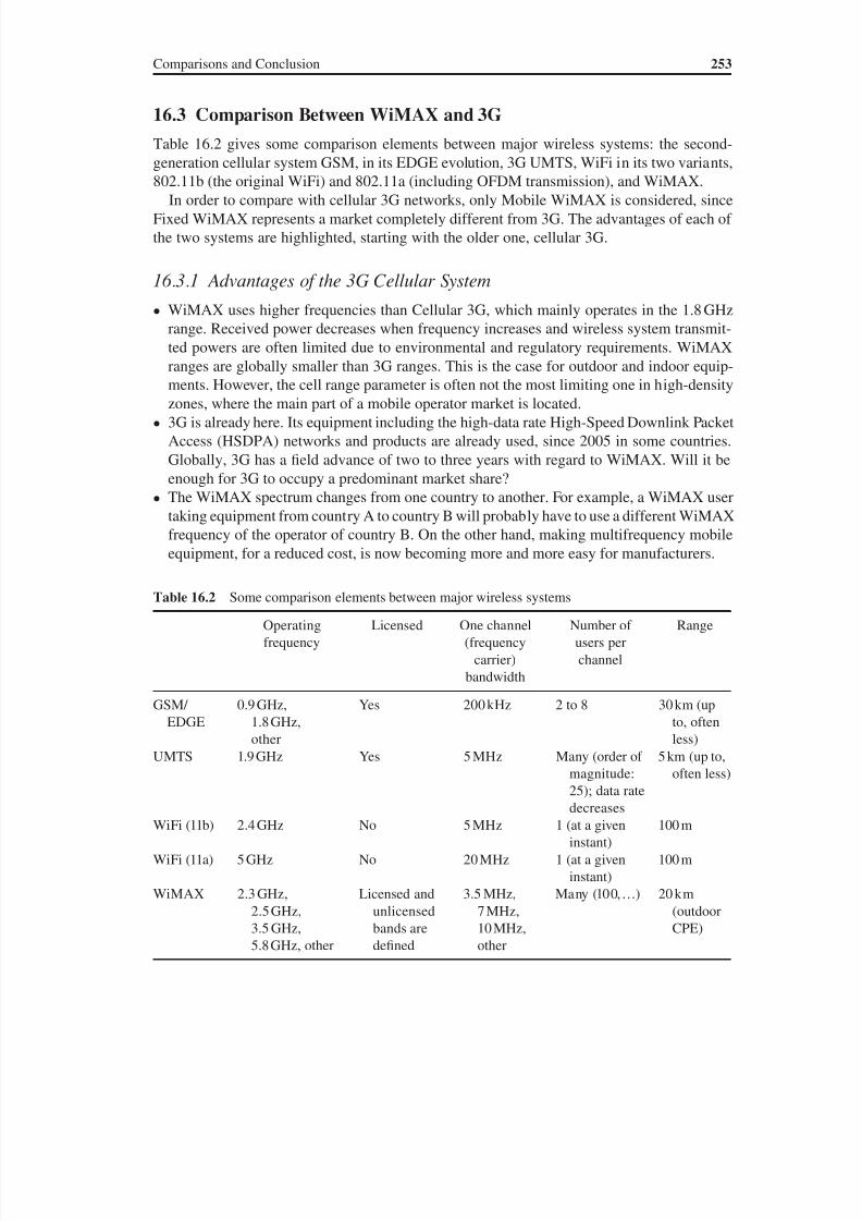
8/10/2019 WiMax-Tech for BBW Access
http://slidepdf.com/reader/full/wimax-tech-for-bbw-access 266/293
Comparisons and Conclusion 253
16.3 Comparison Between WiMAX and 3G
Table 16.2 gives some comparison elements between major wireless systems: the second-
generation cellular system GSM, in its EDGE evolution, 3G UMTS, WiFi in its two variants,
802.11b (the original WiFi) and 802.11a (including OFDM transmission), and WiMAX.In order to compare with cellular 3G networks, only Mobile WiMAX is considered, since
Fixed WiMAX represents a market completely different from 3G. The advantages of each of
the two systems are highlighted, starting with the older one, cellular 3G.
16.3.1 Advantages of the 3G Cellular System
• WiMAX uses higher frequencies than Cellular 3G, which mainly operates in the 1.8 GHz
range. Received power decreases when frequency increases and wireless system transmit-
ted powers are often limited due to environmental and regulatory requirements. WiMAX
ranges are globally smaller than 3G ranges. This is the case for outdoor and indoor equip-ments. However, the cell range parameter is often not the most limiting one in high-density
zones, where the main part of a mobile operator market is located.
• 3G is already here. Its equipment including the high-data rate High-Speed Downlink Packet
Access (HSDPA) networks and products are already used, since 2005 in some countries.
Globally, 3G has a field advance of two to three years with regard to WiMAX. Will it be
enough for 3G to occupy a predominant market share?
• The WiMAX spectrum changes from one country to another. For example, a WiMAX user
taking equipment from country A to country B will probably have to use a different WiMAX
frequency of the operator of country B. On the other hand, making multifrequency mobile
equipment, for a reduced cost, is now becoming more and more easy for manufacturers.
Table 16.2 Some comparison elements between major wireless systems
Operating
frequency
Licensed One channel
(frequency
carrier)
bandwidth
Number of
users per
channel
Range
GSM/
EDGE
0.9 GHz,
1.8 GHz,
other
Yes 200 kHz 2 to 8 30 km (up
to, often
less)UMTS 1.9 GHz Yes 5 MHz Many (order of
magnitude:
25); data rate
decreases
5 km (up to,
often less)
WiFi (11b) 2.4 GHz No 5 MHz 1 (at a given
instant)
100 m
WiFi (11a) 5 GHz No 20 MHz 1 (at a given
instant)
100 m
WiMAX 2.3 GHz,
2.5 GHz,
3.5 GHz,5.8 GHz, other
Licensed and
unlicensed
bands aredefined
3.5 MHz,
7 MHz,
10 MHz,other
Many (100,…) 20 km
(outdoor
CPE)
8/10/2019 WiMax-Tech for BBW Access
http://slidepdf.com/reader/full/wimax-tech-for-bbw-access 267/293
254 WiMAX: Technology for Broadband Wireless Access
• Some countries have restrictions on WiMAX frequency use, i.e. WiMAX operators can be
forbidden to deploy mobility by the regulator.
• Cellular 3G has long had the exclusive support of leading manufacturers, such as Nokia.
These companies now seem to be interested in WiMAX while also still remaining very
interested in 3G.
16.3.2 Advantages of the (Mobile) WiMAX System
• The frequency spectrum of WiMAX should be cheaper than 3G system frequencies in
many countries. The UMTS licence sales in Europe, and specifically in Germany and the
UK, reached surprisingly high amounts.
• WiMAX is a very open system as frequently seen in this book: many algorithms are left for
the vendor, which opens the door to optimisation, and connections between different busi-
ness units operating on different parts of the network (core network, radio access network,
services providers, etc.), possibly in the same country, are made easy (see Chapter 13). This
is probably an advantage, but perhaps it might create some interoperability problems in the
first few years?
• The WiMAX PHYsical Layer is based on OFDM, a transmission technique known to have
a relatively high spectrum-use efficiency (with regard to SC CDMA). There are plans to
upgrade 3G by including OFDM and MIMO in it. This evolution is called, for the moment,
LTE (Long-Term Evolution). This gives a time advance for WiMAX in the implementation
of OFDM.
• WiMAX is an all-IP technology. This is not the case for the 3G system where many inter-
mediate protocols (tunnelling, etc.) made for the first versions of 3G are not all-IP. How-ever, evolution of 3G should provide end-to-end IP (or all-IP).
• WiMAX has a strong support of some industry giants, such as Intel, KT, Samsung and
many others.
Taking into account all these observations, it is very difficult to decide between the two sys-
tems. However, if we want to make a guess, it could be said that there is a place for both of
these two technologies, depending on the market, the country and the application…at least
for a few years to come!
16.4 Final Thoughts and ConclusionIn this book, an attempt has been made to give a global picture of this new and exciting
WiMAX technology. WiMAX is based on two sources: the IEEE 802.16 standard, includ-
ing its amendments, and the WiMAX Forum Group documents. Evidently, this book does
not replace these documents, but it is hoped that it will provide a clear introduction to the
subject.
WiMAX has a large number of mechanisms and is expected to be used for many applica-
tions. The near future will tell which of these mechanisms will be implemented, how they will
be implemented and the mechanisms that will be updated by the standardisation bodies.
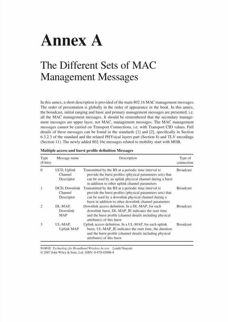
8/10/2019 WiMax-Tech for BBW Access
http://slidepdf.com/reader/full/wimax-tech-for-bbw-access 268/293
Annex AThe Different Sets of MACManagement Messages
In this annex, a short description is provided of the main 802.16 MAC management messages.
The order of presentation is globally in the order of appearance in the book. In this annex,
the broadcast, initial ranging and basic and primary management messages are presented, i.e.
all the MAC management messages. It should be remembered that the secondary manage-
ment messages are upper layer, not MAC, management messages. The MAC management
messages cannot be carried on Transport Connections, i.e. with Transport CID values. Full
details of these messages can be found in the standards [1] and [2], specifically in Section
6.3.2.3 of the standard and the related PHYsical layers part (Section 8) and TLV encodings
(Section 11). The newly added 802.16e messages related to mobility start with MOB.
Multiple access and burst profile definition Messages
Type
(8 bits)
Message name Description Type of
connection
0 UCD, Uplink
Channel
Descriptor
Transmitted by the BS at a periodic time interval to
provide the burst profiles (physical parameters sets) that
can be used by an uplink physical channel during a burst
in addition to other uplink channel parameters
Broadcast
1 DCD, Downlink
Channel
Descriptor
Transmitted by the BS at a periodic time interval to
provide the burst profiles (physical parameters sets) that
can be used by a downlink physical channel during a
burst in addition to other downlink channel parameters
Broadcast
2 DL-MAP,
Downlink
MAP
Downlink access definition. In a DL-MAP, for each
downlink burst, DL-MAP_IE indicates the start time
and the burst profile (channel details including physical
attributes) of this burst
Broadcast
3 UL-MAP,
Uplink MAP
Uplink access definition. In a UL-MAP, for each uplink
burst, UL-MAP_IE indicates the start time, the duration
and the burst profile (channel details including physical
attributes) of this burst
Broadcast
WiMAX: Technology for Broadband Wireless Access Loutfi Nuaymi
© 2007 John Wiley & Sons, Ltd. ISBN: 0-470-02808-4
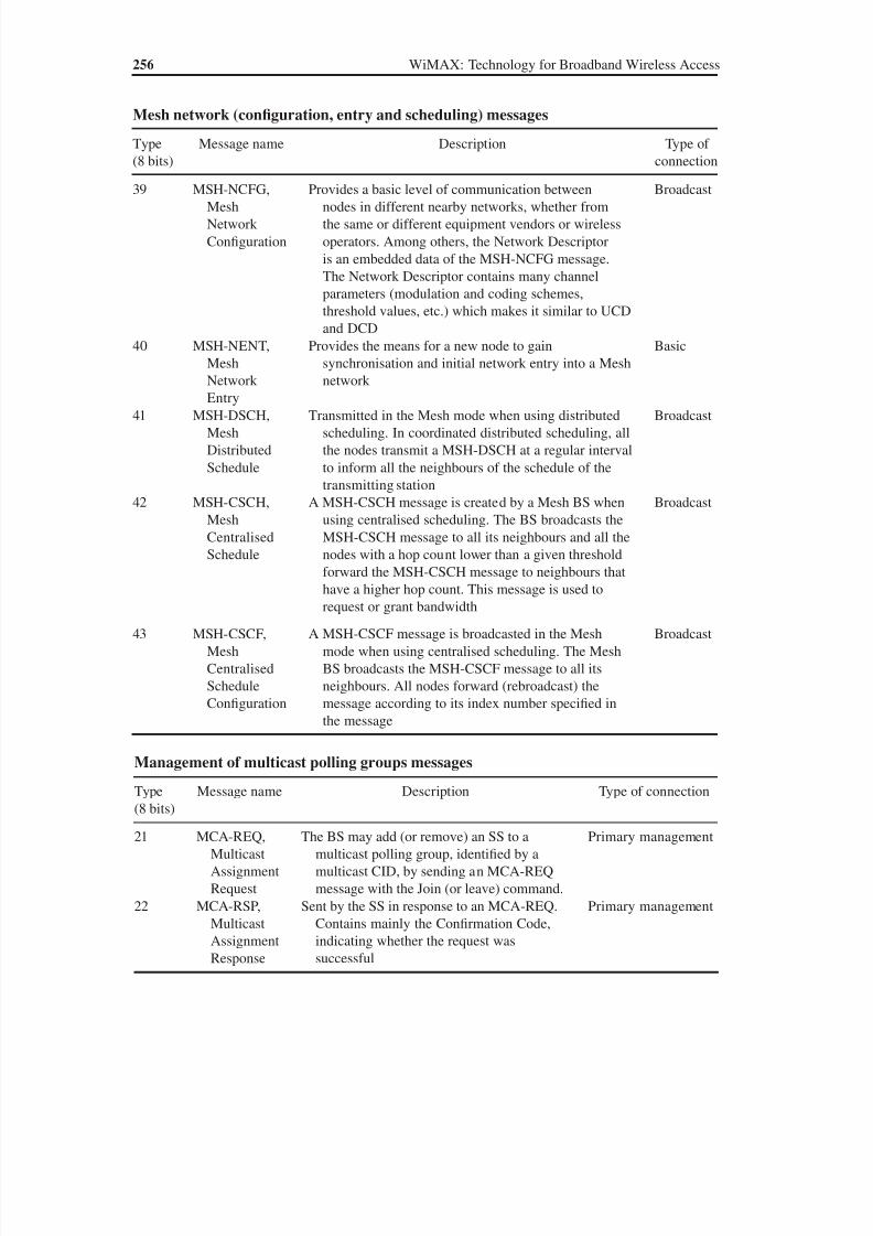
8/10/2019 WiMax-Tech for BBW Access
http://slidepdf.com/reader/full/wimax-tech-for-bbw-access 269/293
256 WiMAX: Technology for Broadband Wireless Access
Mesh network (configuration, entry and scheduling) messages
Type
(8 bits)
Message name Description Type of
connection
39 MSH-NCFG,Mesh
Network
Configuration
Provides a basic level of communication betweennodes in different nearby networks, whether from
the same or different equipment vendors or wireless
operators. Among others, the Network Descriptor
is an embedded data of the MSH-NCFG message.
The Network Descriptor contains many channel
parameters (modulation and coding schemes,
threshold values, etc.) which makes it similar to UCD
and DCD
Broadcast
40 MSH-NENT,
Mesh
Network
Entry
Provides the means for a new node to gain
synchronisation and initial network entry into a Mesh
network
Basic
41 MSH-DSCH,
Mesh
Distributed
Schedule
Transmitted in the Mesh mode when using distributed
scheduling. In coordinated distributed scheduling, all
the nodes transmit a MSH-DSCH at a regular interval
to inform all the neighbours of the schedule of the
transmitting station
Broadcast
42 MSH-CSCH,
Mesh
Centralised
Schedule
A MSH-CSCH message is created by a Mesh BS when
using centralised scheduling. The BS broadcasts the
MSH-CSCH message to all its neighbours and all the
nodes with a hop count lower than a given threshold
forward the MSH-CSCH message to neighbours that
have a higher hop count. This message is used to
request or grant bandwidth
Broadcast
43 MSH-CSCF,
Mesh
Centralised
Schedule
Configuration
A MSH-CSCF message is broadcasted in the Mesh
mode when using centralised scheduling. The Mesh
BS broadcasts the MSH-CSCF message to all its
neighbours. All nodes forward (rebroadcast) the
message according to its index number specified in
the message
Broadcast
Management of multicast polling groups messages
Type
(8 bits)
Message name Description Type of connection
21 MCA-REQ,
Multicast
Assignment
Request
The BS may add (or remove) an SS to a
multicast polling group, identified by a
multicast CID, by sending an MCA-REQ
message with the Join (or leave) command.
Primary management
22 MCA-RSP,
Multicast
AssignmentResponse
Sent by the SS in response to an MCA-REQ.
Contains mainly the Confirmation Code,
indicating whether the request wassuccessful
Primary management
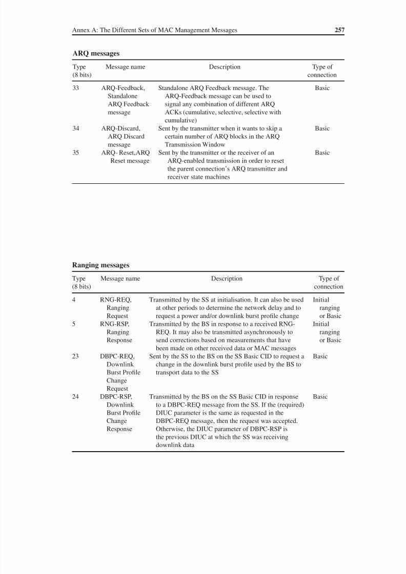
8/10/2019 WiMax-Tech for BBW Access
http://slidepdf.com/reader/full/wimax-tech-for-bbw-access 270/293
ARQ messages
Type
(8 bits)
Message name Description Type of
connection
33 ARQ-Feedback,Standalone
ARQ Feedback
message
Standalone ARQ Feedback message. TheARQ-Feedback message can be used to
signal any combination of different ARQ
ACKs (cumulative, selective, selective with
cumulative)
Basic
34 ARQ-Discard,
ARQ Discard
message
Sent by the transmitter when it wants to skip a
certain number of ARQ blocks in the ARQ
Transmission Window
Basic
35 ARQ- Reset,ARQ
Reset message
Sent by the transmitter or the receiver of an
ARQ-enabled transmission in order to reset
the parent connection’s ARQ transmitter and
receiver state machines
Basic
Ranging messages
Type
(8 bits)
Message name Description Type of
connection
4 RNG-REQ,
Ranging
Request
Transmitted by the SS at initialisation. It can also be used
at other periods to determine the network delay and to
request a power and/or downlink burst profile change
Initial
ranging
or Basic
5 RNG-RSP,
Ranging
Response
Transmitted by the BS in response to a received RNG-
REQ. It may also be transmitted asynchronously to
send corrections based on measurements that have
been made on other received data or MAC messages
Initial
ranging
or Basic
23 DBPC-REQ,
Downlink
Burst Profile
Change
Request
Sent by the SS to the BS on the SS Basic CID to request a
change in the downlink burst profile used by the BS to
transport data to the SS
Basic
24 DBPC-RSP,
Downlink
Burst Profile
Change
Response
Transmitted by the BS on the SS Basic CID in response
to a DBPC-REQ message from the SS. If the (required)
DIUC parameter is the same as requested in the
DBPC-REQ message, then the request was accepted.
Otherwise, the DIUC parameter of DBPC-RSP is
the previous DIUC at which the SS was receivingdownlink data
Basic
Annex A: The Different Sets of MAC Management Messages 257

8/10/2019 WiMax-Tech for BBW Access
http://slidepdf.com/reader/full/wimax-tech-for-bbw-access 271/293
258 WiMAX: Technology for Broadband Wireless Access
SS basic capability negotiation messages
Type (8 bits) Message name Description Type of
connection
26 SBC-REQ, SS Basic
Capability Request
Transmitted by the SS during
initialisation to inform the BS
of its basic capabilities; mainly
Physical Parameters and Bandwidth
Allocation supported
Basic
27 SBC-RSP, SS
Basic CapabilityResponse
Transmitted by the BS in response to an
SBC-REQ. Indicates the intersectionof the SS and the BS capabilities
Basic
Dynamic service management (creation, change and deletion) messages
Type
(8 bits)
Message name Description Type of
connection
11 DSA-REQ, DynamicService Addition
Request
Sent by an SS or BS to create a new serviceflow. Service flow attributes, including QoS
parameters are indicated
PrimaryManagement
12 DSA-RSP, Dynamic
Service Addition
Response
Generated in response to a received DSA-
REQ; indicates whether the creation of the
service flow was successful or rejected
Primary
management
13 DSA-ACK, Dynamic
Service Addition
Acknowledge
Generated in response to a received DSA-RSP Primary
management
14 DSC-REQ, Dynamic
Service Change
Request
Sent by an SS or BS to change dynamically the
parameters of an existing service flow
Primary
management
15 DSC-RSP, Dynamic
Service Change
Response
Generated in response to a received DSC-REQ Primary
management
16 DSC-ACK, Dynamic
Service Addition
Acknowledge
Generated in response to a received DSC-RSP Primary
management
17 DSD-REQ, Dynamic
Service Deletion
Request
Sent by an SS or BS to delete an existing
service flow
Primary
management
18 DSD-RSP, Dynamic
Service Deletion
Response
Generated in response to a received DSD-REQ Primary
management
30 DSX-RVD, DSx
Received Message
Generated by the BS to inform the SS that
the BS has correctly received a DSx (DSA
or DSC)-REQ message. The DSx-RSP
message is transmitted only after the DSx-
REQ is authenticated
Primary
management

8/10/2019 WiMax-Tech for BBW Access
http://slidepdf.com/reader/full/wimax-tech-for-bbw-access 272/293
Registration messages
Type
(8 bits)
Message name Description Type of
connection
6 REG-REQ,Registration
Request
Sent by the SS in order to register with the BS.Indicates supported management parameters,
CS capabilities, IP mode, etc.
Primarymanagement
7 REG-RSP,
Registration
Response
Sent by the BS in response to a REG-REQ
message. Confirms or not authentication.
Responds to REG-REQ capability indications
Primary
management
29 DREG-CMD, De/
Re-registration
Command
Transmitted by the BS to force the SS to change its
access state (stop using the current channel, use
it again, use it with restrictions, etc.). Unsolicited
or in response to an SS DREG-REQ message
Basic
49 DREG-REQ, SS
De-registration
Request message
Sent by the SS to the BS in order to notify the BS
of the SS de-registration request from the BS
and the network
Basic
SS reset message
Type
(8 bits)
Message name Description Type of
connection
25 RES-CMD, Reset
Command
Transmitted by the BS to force the SS to reset itself,
reinitialise its MAC and repeat initial system access
Basic
Configuration file TFTP transmission complete messages
Type
(8 bits)
Message name Description Type of
connection
31 TFTP-CPLT,
Config File TFTP
Complete message
When the configuration file TFTP download has
completed successfully, the SS notifies the BS
by transmitting a TFTP-CPLT message
Primary
management
32 TFTP-RSP, Config
File TFTP
Complete Response
In response to TFTP-CPLT, the BS (normally)
sends a TFTP-RSP message with an ‘OK’
response
Primary
management
Radio resource management messages
Type
(8 bits)
Message name Description Type of
connection
36 REP-REQ, channel
measurement
Report Request
Sent by the BS to the SS in order to require RSSI
(received power level) and CINR channel measurement
reports. In license-exempt bands, the REP-REQ
message is also used to request the results of the DFSmeasurements that the BS has previously scheduled
Basic
(continued overleaf )
Annex A: The Different Sets of MAC Management Messages 259
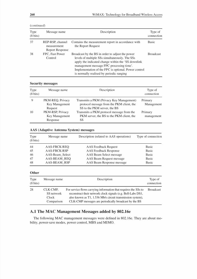
8/10/2019 WiMax-Tech for BBW Access
http://slidepdf.com/reader/full/wimax-tech-for-bbw-access 273/293
260 WiMAX: Technology for Broadband Wireless Access
A.1 The MAC Management Messages added by 802.16eThe following MAC management messages were defined in 802.16e. They are about mo-
bility, power-save modes, power control, MBS and MIMO.
AAS (Adaptive Antenna System) messages
Type
(8 bits)
Message name Description (related to AAS operations) Type of connection
44 AAS-FBCK-REQ AAS Feedback Request Basic
45 AAS-FBCK-RSP AAS Feedback Response Basic
46 AAS-Beam_Select AAS Beam Select message Basic
47 AAS-BEAM_REQ AAS Beam Request message Basic
48 AAS-BEAM_RSP AAS Beam Response message Basic
Security messagesType
(8 bits)
Message name Description Type of
connection
9 PKM-REQ, Privacy
Key Management
Request
Transmits a PKM (Privacy Key Management)
protocol message from the PKM client, the
SS to the PKM server, the BS
Primary
Management
10 PKM-RSP, Privacy
Key Management
Response
Transmits a PKM protocol message from the
PKM server, the BS to the PKM client, the
SS
Primary
management
Other
Type
(8 bits)
Message name Description Type of
connection
28 CLK-CMP,
SS network
Clock
Comparison
For service flows carrying information that requires the SSs to
reconstruct their network clock signals (e.g. Bell-Labs DS1,
also known as T1, 1.536 Mb/s circuit transmission system),
CLK-CMP messages are periodically broadcast by the BS
Broadcast
Type
(8 bits)
Message name Description Type of
connection
37 REP-RSP, channelmeasurement
Report Response
Contains the measurement report in accordance withthe Report Request
Basic
38 FPC, Fast Power
Control
Broadcast by the BS in order to adjust the power
levels of multiple SSs simultaneously. The SSs
apply the indicated change within the ‘SS downlink
management message FPC processing time’.
Implementation of the FPC is optional. Power control
is normally realised by periodic ranging
Broadcast
(continued )

8/10/2019 WiMax-Tech for BBW Access
http://slidepdf.com/reader/full/wimax-tech-for-bbw-access 274/293
Power control mode messages
Type
(8 bits)
Message name Description Type of
connection
63 PMC_REQ, Powercontrol Mode
Change Request
Sent from the SS to the BS, PMC_REQ is used torequest to change the power control mode or to
answer PMC_RSP
Basic
64 PMC_RSP,
Power control
Mode Change
Response
The decision of the change of the power control
mode (open loop or closed loop) is done at the BS.
This decision is indicated by the PMC_RSP MAC
message
Basic
MBS message
Type
(8 bits)
Message
name
Description Type of
connection
62 MBS_MAP Sent by the BS, on an MBS portion to describe the MBS
connections serviced by this MBS portion. If MBS_MAP
is not sent, these connections are described in the DL-MAP
—
MIMO precoding setup message
Type
(8 bits)
Message name Description Type of
connection
65 PRC-LT-CTRL,
Setup/Tear-
down of Long-
Term MIMO
Precoding
The BS can set up long-term MIMO precoding with
feedback from a particular SS by sending this
message to this SS. The BS can also use this
message to tear down the long-term precoding with
feedback
Basic
Annex A: The Different Sets of MAC Management Messages 261
Handover messages
Type(8 bits)
Message name Description Type ofconnection
53 MOB_NBR-ADV,
Neighbour
Advertisement
Broadcasted by a BS; provides channel
information about neighbouring BSs
normally provided by each BS’s DCD/UCD
message transmissions
Broadcast,
Primary
management
54 MOB_SCN-REQ,
Scanning interval
allocation Request
Sent by the SS (MS) to request a scanning
interval for the purpose of seeking available
BSs and determining their suitability as
targets for handover
Basic
55 MOB_SCN-RSP,Scanning interval
allocation Response
Sent by the BS to start MS scan reporting withor without scanning allocation
Basic
(continued overleaf )
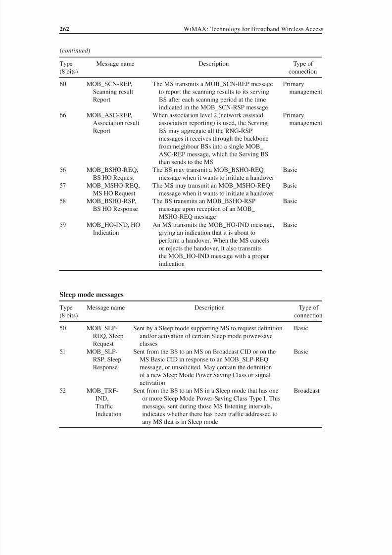
8/10/2019 WiMax-Tech for BBW Access
http://slidepdf.com/reader/full/wimax-tech-for-bbw-access 275/293
262 WiMAX: Technology for Broadband Wireless Access
Sleep mode messages
Type
(8 bits)
Message name Description Type of
connection
50 MOB_SLP-
REQ, SleepRequest
Sent by a Sleep mode supporting MS to request definition
and/or activation of certain Sleep mode power-saveclasses
Basic
51 MOB_SLP-
RSP, Sleep
Response
Sent from the BS to an MS on Broadcast CID or on the
MS Basic CID in response to an MOB_SLP-REQ
message, or unsolicited. May contain the definition
of a new Sleep Mode Power Saving Class or signal
activation
Basic
52 MOB_TRF-
IND,
Traffic
Indication
Sent from the BS to an MS in a Sleep mode that has one
or more Sleep Mode Power-Saving Class Type I. This
message, sent during those MS listening intervals,
indicates whether there has been traffic addressed to
any MS that is in Sleep mode
Broadcast
Type
(8 bits)
Message name Description Type of
connection
60 MOB_SCN-REP,Scanning result
Report
The MS transmits a MOB_SCN-REP messageto report the scanning results to its serving
BS after each scanning period at the time
indicated in the MOB_SCN-RSP message
Primarymanagement
66 MOB_ASC-REP,
Association result
Report
When association level 2 (network assisted
association reporting) is used, the Serving
BS may aggregate all the RNG-RSP
messages it receives through the backbone
from neighbour BSs into a single MOB_
ASC-REP message, which the Serving BS
then sends to the MS
Primary
management
56 MOB_BSHO-REQ,BS HO Request
The BS may transmit a MOB_BSHO-REQmessage when it wants to initiate a handover
Basic
57 MOB_MSHO-REQ,
MS HO Request
The MS may transmit an MOB_MSHO-REQ
message when it wants to initiate a handover
Basic
58 MOB_BSHO-RSP,
BS HO Response
The BS transmits an MOB_BSHO-RSP
message upon reception of an MOB_
MSHO-REQ message
Basic
59 MOB_HO-IND, HO
Indication
An MS transmits the MOB_HO-IND message,
giving an indication that it is about to
perform a handover. When the MS cancels
or rejects the handover, it also transmits
the MOB_HO-IND message with a proper
indication
Basic
(continued )

8/10/2019 WiMax-Tech for BBW Access
http://slidepdf.com/reader/full/wimax-tech-for-bbw-access 276/293
Idle mode message
Type
(8 bits)
Message name Description Type of
connection
61 MOB_PAG-ADV,BS broadcast
PAGing
Sent by the BS on the Broadcast CID or Idle modemulticast CID during the BS Paging Interval.
Indicates, for a number of Idle mode supporting
MSs, the requirement of performing ranging to
establish the location, acknowledge a message or to
Enter Network
Broadcast
Present versions of the IEEE 802.16g amendment draft include some new MAC manage-
ment messages. This amendment should be published before the end of the first half of 2007
(October 2006 information).
Annex A: The Different Sets of MAC Management Messages 263
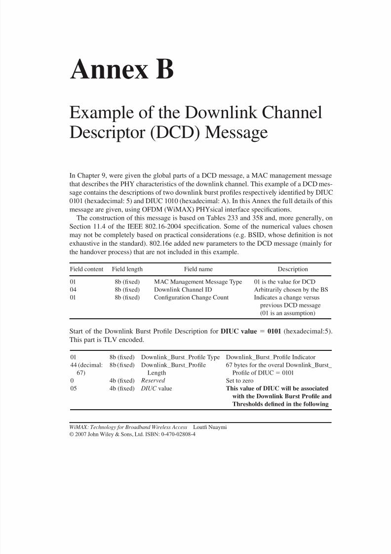
8/10/2019 WiMax-Tech for BBW Access
http://slidepdf.com/reader/full/wimax-tech-for-bbw-access 277/293
Annex BExample of the Downlink ChannelDescriptor (DCD) Message
In Chapter 9, were given the global parts of a DCD message, a MAC management message
that describes the PHY characteristics of the downlink channel. This example of a DCD mes-
sage contains the descriptions of two downlink burst profiles respectively identified by DIUC
0101 (hexadecimal: 5) and DIUC 1010 (hexadecimal: A). In this Annex the full details of this
message are given, using OFDM (WiMAX) PHYsical interface specifications.
The construction of this message is based on Tables 233 and 358 and, more generally, on
Section 11.4 of the IEEE 802.16-2004 specification. Some of the numerical values chosen
may not be completely based on practical considerations (e.g. BSID, whose definition is not
exhaustive in the standard). 802.16e added new parameters to the DCD message (mainly for
the handover process) that are not included in this example.
Start of the Downlink Burst Profile Description for DIUC value 0101 (hexadecimal:5).
This part is TLV encoded.
01 8b (fixed) Downlink_Burst_Profile Type Downlink_Burst_Profile Indicator
44 (decimal:
67)
8b (fixed) Downlink_Burst_Profile
Length
67 bytes for the overal Downlink_Burst_
Profile of DIUC 0101
0 4b (fixed) Reserved Set to zero
05 4b (fixed) DIUC value This value of DIUC will be associatedwith the Downlink Burst Profile andThresholds defined in the following
Field content Field length Field name Description
01 8b (fixed) MAC Management Message Type 01 is the value for DCD
04 8b (fixed) Downlink Channel ID Arbitrarily chosen by the BS
01 8b (fixed) Configuration Change Count Indicates a change versus
previous DCD message
(01 is an assumption)
WiMAX: Technology for Broadband Wireless Access Loutfi Nuaymi
© 2007 John Wiley & Sons, Ltd. ISBN: 0-470-02808-4
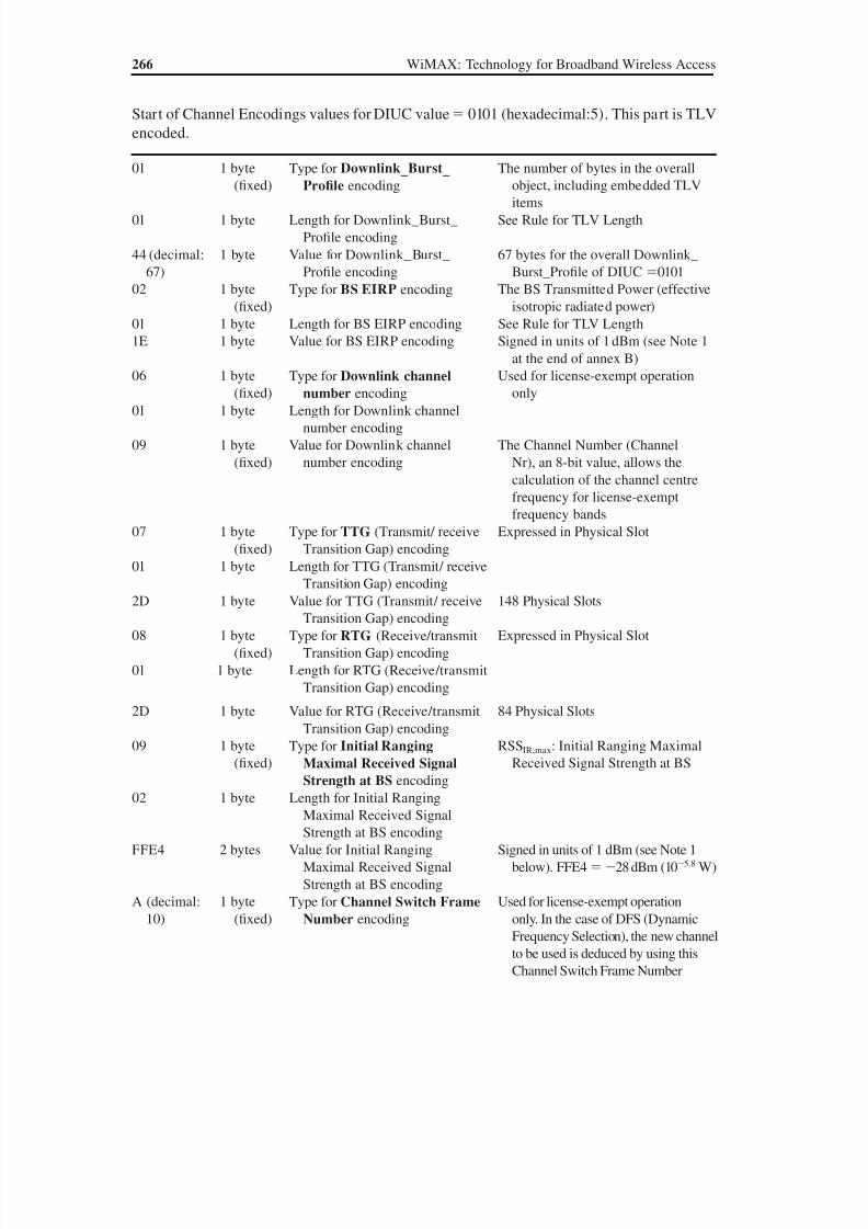
8/10/2019 WiMax-Tech for BBW Access
http://slidepdf.com/reader/full/wimax-tech-for-bbw-access 278/293
266 WiMAX: Technology for Broadband Wireless Access
Start of Channel Encodings values for DIUC value 0101 (hexadecimal:5). This part is TLV
encoded.
01 1 byte
(fixed)
Type for Downlink_Burst_
Profile encoding
The number of bytes in the overall
object, including embedded TLVitems
01 1 byte Length for Downlink_Burst_
Profile encoding
See Rule for TLV Length
44 (decimal:
67)
1 byte Value for Downlink_Burst_
Profile encoding
67 bytes for the overall Downlink_
Burst_Profile of DIUC 0101
02 1 byte
(fixed)
Type for BS EIRP encoding The BS Transmitted Power (effective
isotropic radiated power)
01 1 byte Length for BS EIRP encoding See Rule for TLV Length
1E 1 byte Value for BS EIRP encoding Signed in units of 1 dBm (see Note 1
at the end of annex B)
06 1 byte(fixed)
Type for Downlink channelnumber encoding
Used for license-exempt operationonly
01 1 byte Length for Downlink channel
number encoding
09 1 byte
(fixed)
Value for Downlink channel
number encoding
The Channel Number (Channel
Nr), an 8-bit value, allows the
calculation of the channel centre
frequency for license-exempt
frequency bands
07 1 byte
(fixed)
Type for TTG (Transmit/ receive
Transition Gap) encoding
Expressed in Physical Slot
01 1 byte Length for TTG (Transmit/ receive
Transition Gap) encoding
2D 1 byte Value for TTG (Transmit/ receive
Transition Gap) encoding
148 Physical Slots
08 1 byte
(fixed)
Type for RTG (Receive/transmit
Transition Gap) encoding
Expressed in Physical Slot
01 1 byte Length for RTG (Receive/transmit
Transition Gap) encoding
2D 1 byte Value for RTG (Receive/transmit
Transition Gap) encoding
84 Physical Slots
09 1 byte(fixed)
Type for Initial RangingMaximal Received SignalStrength at BS encoding
RSSIR,max: Initial Ranging MaximalReceived Signal Strength at BS
02 1 byte Length for Initial Ranging
Maximal Received Signal
Strength at BS encoding
FFE4 2 bytes Value for Initial Ranging
Maximal Received Signal
Strength at BS encoding
Signed in units of 1 dBm (see Note 1
below). FFE4 28 dBm (105.8 W)
A (decimal:
10)
1 byte
(fixed)
Type for Channel Switch FrameNumber encoding
Used for license-exempt operation
only. In the case of DFS (Dynamic
Frequency Selection), the new channelto be used is deduced by using this
Channel Switch Frame Number

8/10/2019 WiMax-Tech for BBW Access
http://slidepdf.com/reader/full/wimax-tech-for-bbw-access 279/293
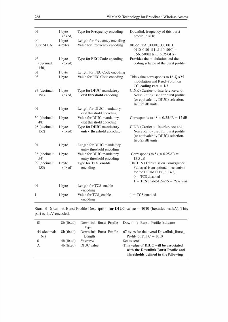
8/10/2019 WiMax-Tech for BBW Access
http://slidepdf.com/reader/full/wimax-tech-for-bbw-access 280/293
268 WiMAX: Technology for Broadband Wireless Access
Start of Downlink Burst Profile Description for DIUC value 1010 (hexadecimal:A). This
part is TLV encoded.
01 1 byte
(fixed)
Type for Frequency encoding Downlink frequency of this burst
profile in kHz
04 1 byte Length for Frequency encoding
0036 5FEA 4 bytes Value for Frequency encoding 00365FEA (0000,0000,0011,
0110, 0101,1111,1110,1010) 3 563 500 kHz (3.5635 GHz)
96
(decimal:
150)
1 byte
(fixed)
Type for FEC Code encoding Provides the modulation and the
coding scheme of the burst profile
01 1 byte Length for FEC Code encoding
03 1 byte Value for FEC Code encoding This value corresponds to 16-QAM
modulation and Reed–Solomon
CC, coding rate 1/297 (decimal:
151)
1 byte
(fixed)
Type for DIUC mandatoryexit threshold encoding
CINR (Carrier-to-Interference-and-
Noise Ratio) used for burst profile
(or equivalently DIUC) selection.
In 0.25 dB units.
01 1 byte Length for DIUC mandatory
exit threshold encoding
30 (decimal:
48)
1 byte Value for DIUC mandatory
exit threshold encoding
Corresponds to 48 0.25 dB 12 dB
98 (decimal:
152)
1 byte
(fixed)
Type for DIUC mandatoryentry threshold encoding
CINR (Carrier-to-Interference-and-
Noise Ratio) used for burst profile
(or equivalently DIUC) selection.
In 0.25 dB units.
01 1 byte Length for DIUC mandatoryentry threshold encoding
36 (decimal:
54)
1 byte Value for DIUC mandatory
entry threshold encoding
Corresponds to 54 0.25 dB
13.5 dB
99 (decimal:
153)
1 byte
(fixed)
Type for TCS_enableencoding
The TCS (Transmission Convergence
Sublayer) is an optional mechanism
for the OFDM PHY( 8.1.4.3)
0 TCS disabled
1 TCS enabled 2–255 Reserved
01 1 byte Length for TCS_enable
encoding
1 1 byte Value for TCS_enableencoding
1 TCS enabled
01 8b (fixed) Downlink_Burst_Profile
Type
Downlink_Burst_Profile Indicator
44 (decimal:
67)
8b (fixed) Downlink_Burst_Profile
Length
67 bytes for the overal Downlink_Burst_
Profile of DIUC 1010
0 4b (fixed) Reserved Set to zero
A 4b (fixed) DIUC value This value of DIUC will be associatedwith the Downlink Burst Profile andThresholds defined in the following

8/10/2019 WiMax-Tech for BBW Access
http://slidepdf.com/reader/full/wimax-tech-for-bbw-access 281/293
Start of Channel Encodings values for DIUC value 1010 (hexadecimal:A). This part is
TLV encoded.
01 1 byte
(fixed)
Type for Downlink_Burst_Profile encoding
The number of bytes in the overall
object, including embedded TLV
items
01 1 byte Length for Downlink_Burst_
Profile encoding
See Rule for TLV Length
44
(decimal:
67)
1 byte Value for Downlink_Burst_
Profile encoding
67 bytes for the overall Downlink_
Burst_Profile of DIUC 1010
02 1 byte
(fixed)
Type for BS EIRP encoding The BS Transmitted Power (effective
isotropic radiated power)
01 1 byte Length for BS EIRP encoding See Rule for TLV Length1E 1 byte Value for BS EIRP encoding Signed in units of 1 dBm (see Note 1
below). 1E 30 dBm (1 W)
06 1 byte
(fixed)
Type for Downlink channelnumber encoding
Used for license-exempt operation only
01 1 byte Length for Downlink channel
number encoding
09 1 byte
(fixed)
Value for Downlink channel
number encoding
The Channel Number (Channel Nr),
an 8-bit value, allows the calculation
of the channel centre frequency for
license-exempt frequency bands
07 1 byte(fixed)
Type for TTG (Transmit/receive Transition Gap)
encoding
Expressed in Physical Slot
01 1 byte Length for TTG (Transmit/
receive Transition Gap)
encoding
3C 1 byte Value for TTG (Transmit/
receive Transition Gap)
encoding
148 Physical Slots
08 1 byte
(fixed)
Type for RTG (Receive/
transmit Transition Gap)
encoding
Expressed in Physical Slot
01 1 byte Length for RTG (Receive/
transmit Transition Gap)
encoding
3C 1 byte Value for RTG (Receive/
transmit Transition Gap)
encoding
84 Physical Slots
09 1 byte
(fixed)
Type for Initial RangingMaximal Received SignalStrength at BS encoding
RSSIR,max: Initial Ranging Maximal
Received Signal Strength at the BS
02 1 byte Length for Initial Ranging
Maximal Received Signal
Strength at BS encoding
(continued overleaf )
Annex B: Example of the Downlink Channel Descriptor (DCD) Message 269

8/10/2019 WiMax-Tech for BBW Access
http://slidepdf.com/reader/full/wimax-tech-for-bbw-access 282/293
270 WiMAX: Technology for Broadband Wireless Access
FFE6 2 bytes Value for Initial Ranging
Maximal Received Signal
Strength at BS encoding
Signed in units of 1 dBm (see Note 1
below). FFE6 26 dBm (105.6 W)
A (decimal:
10)
1 byte
(fixed)
Type for Channel SwitchFrame Number encoding
Used for license-exempt operation
only. In the case of DFS (Dynamic
Frequency Selection), the new channel
to be used is deduced by using this
Channel Switch Frame Number
03 1 byte Length for Channel Switch
Frame Number encoding
See Rule for TLV Length
000003 3 bytes Value for Channel Switch
Frame Number encoding
3
C (decimal:
12)
1 byte
(fixed)
Type for Downlink centre
frequency encoding
The centre of the frequency band in
which a base station (BS) or SS isintended to transmit in kHz
04 1 byte Length for Downlink centre
frequency encoding
0036 5240 4 bytes Value for Downlink centre
frequency encoding
00365240 (0000,0000,0011,0110,
0101,1111,1110,1010)
3 560 000 kHz (3.56 GHz)
D (decimal:
13)
1 byte
(fixed)
Type for Base Station ID
encoding
The Base Station ID is a 48-bit long
field identifying the BS (not the
MAC address)
06 1 byte Length for Base Station ID
encodingAE54
123456
6 bytes Value for Base Station ID
encoding
The Base Station ID is programmable.
The MS 24 bits must be used as the
operator ID. A random value has
been chosen here
E (decimal:
14)
1 byte
(fixed)
Type for Frame DurationCode encoding
The Frame Duration Code values are
given in the standard
01 1 byte Length for Frame Duration
Code encoding
04 1 byte Value for Frame Duration
Code encoding
The code corresponding to 10 ms (see
Table 232 of 802.16-2004)
F (decimal:15)
1 byte(fixed)
Type for Frame Numberencoding
The Frame Number is a modulo 212 number (a 12-bit-number) which is
increased by one for every frame
03 1 byte Length for Frame Number
encoding
A0B1EE 3 bytes Value for Frame Number
encoding
The Frame Number of the frame
containing the DCD message
94h
(decimal:
148)
1 byte
(fixed)
Type for MAC versionencoding
Specifies the version of IEEE 802.16
to which the message originator
conforms
01 1 byte Length for MAC version
encoding
04 1 byte Value for MAC version
encoding
Indicates conformance with IEEE Std
802.16-2004
(continued )
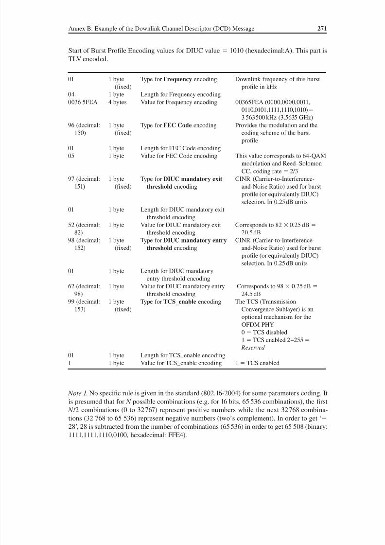
8/10/2019 WiMax-Tech for BBW Access
http://slidepdf.com/reader/full/wimax-tech-for-bbw-access 283/293
Start of Burst Profile Encoding values for DIUC value 1010 (hexadecimal:A). This part is
TLV encoded.
Note 1. No specific rule is given in the standard (802.16-2004) for some parameters coding. It
is presumed that for N possible combinations (e.g. for 16 bits, 65 536 combinations), the first
N /2 combinations (0 to 32 767) represent positive numbers while the next 32 768 combina-
tions (32 768 to 65 536) represent negative numbers (two’s complement). In order to get ‘
28’, 28 is subtracted from the number of combinations (65 536) in order to get 65 508 (binary:
1111,1111,1110,0100, hexadecimal: FFE4).
01 1 byte
(fixed)
Type for Frequency encoding Downlink frequency of this burst
profile in kHz
04 1 byte Length for Frequency encoding
0036 5FEA 4 bytes Value for Frequency encoding 00365FEA (0000,0000,0011,
0110,0101,1111,1110,1010)
3 563 500 kHz (3.5635 GHz)
96 (decimal:
150)
1 byte
(fixed)
Type for FEC Code encoding Provides the modulation and the
coding scheme of the burst
profile
01 1 byte Length for FEC Code encoding
05 1 byte Value for FEC Code encoding This value corresponds to 64-QAM
modulation and Reed–SolomonCC, coding rate 2/3
97 (decimal:
151)
1 byte
(fixed)
Type for DIUC mandatory exitthreshold encoding
CINR (Carrier-to-Interference-
and-Noise Ratio) used for burst
profile (or equivalently DIUC)
selection. In 0.25 dB units
01 1 byte Length for DIUC mandatory exit
threshold encoding
52 (decimal:
82)
1 byte Value for DIUC mandatory exit
threshold encoding
Corresponds to 82 0.25 dB
20.5 dB
98 (decimal:
152)
1 byte
(fixed)
Type for DIUC mandatory entry
threshold encoding
CINR (Carrier-to-Interference-
and-Noise Ratio) used for burstprofile (or equivalently DIUC)
selection. In 0.25 dB units
01 1 byte Length for DIUC mandatory
entry threshold encoding
62 (decimal:
98)
1 byte Value for DIUC mandatory entry
threshold encoding
Corresponds to 98 0.25 dB
24.5 dB
99 (decimal:
153)
1 byte
(fixed)
Type for TCS_enable encoding The TCS (Transmission
Convergence Sublayer) is an
optional mechanism for the
OFDM PHY
0 TCS disabled1 TCS enabled 2–255
Reserved
01 1 byte Length for TCS_enable encoding
1 1 byte Value for TCS_enable encoding 1 TCS enabled
Annex B: Example of the Downlink Channel Descriptor (DCD) Message 271
8/10/2019 WiMax-Tech for BBW Access
http://slidepdf.com/reader/full/wimax-tech-for-bbw-access 284/293
References
[1] IEEE 802.16-2004, IEEE Standard for Local and Metropolitan Area Networks, Air Interface for
Fixed Broadband Wireless Access Systems, October 2004.
[2] IEEE 802.16e, IEEE Standard for Local and Metropolitan Area Networks, Air Interface for Fixed
Broadband Wireless Access Systems, Amendment 2: Physical and Medium Access Control Layers for Combined Fixed and Mobile Operation in Licensed Bands and Corrigendum 1, February 2006
(Approved: 7 December 2005).
[3] Wikipedia, the free encyclopedia, www.wikipedia.org.
[4] Tanenbaum, A. Computer Networks, Prentice-Hall, August 2002.
[5] Agis, A. et al., Global, interoperable broadband wireless networks: extending WiMAX technol-
ogy to mobility. Intel Technology Journal, August 2004.
[6] WiMAX Forum White Paper, 3rd WiMAX Forum plugfest – test methodology and key learnings,
March 2006.
[7] Recommendation ITU-R M.1652, Dynamic frequency selection (DFS) in wireless access systems
including radio local area networks for the purpose of protecting the radio determination service
in the 5 GHz band, 2003. [8] IEEE 802.16f, IEEE Standard for Local and Metropolitan Area Networks, Air Interface for Fixed
Broadband Wireless Access Systems, Amendment 1: Management Information Base, December
2005.
[9] Lee, W. C. Y., Mobile Cellular Telecommunications: Analog and Digital Systems, McGraw-
Hill, 2000.
[10] WiMAX Forum White Paper, Mobile WiMAX – Part I: a technical overview and performance
evaluation, March 2006.
[11] WiMAX Forum White Paper, Initial certification profiles and the European regulatory frame-
work, September 2004.
[12] van Nee, R. and Prasad, R., OFDM for Wireless Multimedia Communications, Artech House,
2000.[13] Holma, H. and Toksala, A., WCDMA for UMTS, 3rd edn, John Wiley & Sons, Ltd, 2004.
[14] IETF RFC 3095, RObust Header Compression (ROHC): Framework and Four Profiles: RTP,
UDP, ESP, and Uncompressed , C. Bormann et al., July 2001.
[15] IETF RFC 3545, Enhanced Compressed RTP (CRTP) for Links with High Delay, Packet Loss and
Reordering, T. Koren et al., July 2003.
[16] Johnston, D. and Yaghoobi, H., Peering into the WiMAX spec, CommsDesign (http://www.com-
msdesign.com/), January 2004.
[17] IETF RFC 2131, Dynamic Host Configuration Protocol (DHCP), R. Droms, March 1997.
WiMAX: Technology for Broadband Wireless Access Loutfi Nuaymi
© 2007 John Wiley & Sons, Ltd. ISBN: 0-470-02808-4

8/10/2019 WiMax-Tech for BBW Access
http://slidepdf.com/reader/full/wimax-tech-for-bbw-access 285/293
274 References
[18] IETF RFC 2132, DHCP options and BOOTP Vendor Extensions, S. Alexander and R. Droms,
March 1997.
[19] IETF RFC 868, Time Protocol, J. Postel and K. Harrenstien, May 1983.
[20] IETF RFC 1350, The TFTP Protocol (Revision 2), K. Sollins, July 1992.
[21] WiMAX Forum Document, WiMAX end-to-end network systems architecture; Stage 2, Release1: architecture tenets, network reference architecture, reference points, April 2006.
[22] Rappaport, T.S., Wireless Communications; Principles and Practice, Prentice-Hall, 1996.
[23] Recommendation ITU-R P.526-8, Propagation by diffraction, 2003.
[24] Erceg, V., et al., Channel models for fixed wireless applications, IEEE 802.16 Broadband Wireless
Access working group, February 2001.
[25] Recommendation ITU-R P.530-9, Propagation data and prediction methods required for the de-
sign of terrestrial line-of-sight systems, 2001.
[26] WiMAX Forum White Paper, WiMAX deployment considerations for fixed wireless access in the
2.5 GHz and 3.5 GHz licensed bands, June 05.
[27] Lehne, P.H. and Pettersen, M., An overview of smart antenna technology for mobile communica-
tions systems. IEEE Communications Surveys and Tutorials, 2(4), Fourth Quarter 1999.[28] Liberti, J.C. and Rappaport, T.S., Smart Antennas for Wireless Communications: IS-95 and Third
Generation WCDMA Applications, Prentice-Hall, 1999.
[29] Kuchar, A., Taferner, M., Tangemann, M. and Hoek, C., Field trial with GSM/DCS1800 smart
antenna base station. Proceedings of the Vehicular Technology Conference, VTC Fall, September
1999.
[30] Alamouti, S., A simple transmit diversity technique for wireless communications. IEEE Journal
on Selected Areas in Communications, 16(8), October 1998.
[31] Paulraj, A.J. and Papadias, C.B., Space–time processing for wireless communications. IEEE Sig-
nal Processing Magazine, November 1997.
[32] Gesbert, D., Shafi, M., Shiu, D.S., Smith, P.J. and Naguib, A., From theory to practice: an over-
view of MIMO space–time coded wireless systems. IEEE Journal on Selected Areas in Commu-nications, 21(3), April 1998.
[33] WiMAX Forum White Paper, Fixed, nomadic, portable and mobile applications for 802.16-2004
and 802.16e WiMAX networks, November 2005.
[34] WiMAX Forum Document, WiMAX end-to-end network systems architecture; Stage 3, Release
1: detailed protocols and procedures, April 2006.
[35] IETF RFC 1701, Generic Encapsulation Protocol (GRE), S. Hanks et al., October 1994.
[36] IETF RFC 3315, Dynamic Host Configuration Protocol for IPv6 (DHCPv6), R. Droms et al., July
2003.
[37] IETF RFC 2462, IPv6 Stateless Address Autoconfiguration, IETF Standard , S. Thomson et al.,
December 1998.
[38] IETF RFC 3041, Privacy Extensions for Stateless Address Auto-configuration in IPv6 , T. Narten
and R. Draves, January 2001.
[39] IETF RFC 3748, Extensible Authentication Protocol (EAP), B. Aboba et al., June 2004.
[40] IETF RFC 3579, RADIUS (Remote Authentication Dial In User Service) Support for Extensible
Authentication Protocol (EAP), B. Aboba and P. Calhoun, September 2003.
[41] PKCS #1 v2.0, RSA Cryptography Standard , RSA Laboratories, October 1998.
[42] National Technical Information Service (NTIS), FIPS 46-3, Data Encryption Standard (DES),
October 1999; http://www.ntis.gov/.
[43] National Technical Information Service (NTIS), FIPS 197, Advanced Encryption Standard
(AES), November 2001.
[44] National Technical Information Service (NTIS), FIPS 198, The Keyed-Hash Message Authenti-
cation Code (HMAC), March 2002.
8/10/2019 WiMax-Tech for BBW Access
http://slidepdf.com/reader/full/wimax-tech-for-bbw-access 286/293
References 275
[45] IETF RFC 2104, HMAC: Keyed-Hashing for Message Authentication, H. Krawczyk, M. Bellare
and R. Canetti, February 1997.
[46] IETF RFC 4493, The AES-CMAC Algorithm, J.H. Song et al., June 2006.
[47] ITU-T Recommendation X.509 (1997 E), Information technology – open systems interconnection
– the directory: authentication framework, June 1997.[48] IETF RFC 3280, Internet X.509 Public Key Infrastructure Certificate and Certificate Revocation
List (CRL) Profile (eds R. Housley et al.,) April 2002.
[49] National Technical Information Service (NTIS), FIPS 180-1, Secure Hash Standard (SHA-1),
April 1995.
[50] SCTE DSS 00-09, Data over cable service interface specification baseline privacy interface,
DOCSIS SP-BPI-I06-001215, Baseline privacy plus interface specification, December 2000.
[51] IETF RFC 2716, PPP EAP TLS Authentication Protocol, B. Aboba and D. Simon, October
1999.
[52] IETF RFC 4017, Extensible Authentication Protocol (EAP) Method Requirements for Wireless
LANs, D. Stanley et al., March 2005.
[53] IETF RFC 1750, Randomness Recommendations for Security, D. Eastlake et al., December1994.
[54] IETF RFC 4086, Randomness Requirements for Security, D. Eastlake et al., June 2005.
[55] IETF RFC 3610, Counter with CBC-MAC (CCM), D. Whiting et al., September 2003.
[56] IETF RFC 3686, Using Advanced Encryption Standard (AES) Counter Mode with IPsec Encap-
sulating Security Payload (ESP), R. Housley et al., January 2004.
8/10/2019 WiMax-Tech for BBW Access
http://slidepdf.com/reader/full/wimax-tech-for-bbw-access 287/293
Index
16-QAM, see QAM
3G cellular systems, 1, 253–4
64-QAM, see QAM
802.16e, 14
802.16f, 20, 28
802.16g, 20
802.16j, 21
AAA, 208, 216–7
AAS, 14, 195–9
Access Service Network, see ASN
Active mode, 227
Adaptive Antenna System, see AASAdaptive Modulation and Coding,
see AMC
Admission control, 192
Advanced Encryption Standard, see AES
AES, 246–7
Aggregate bandwidth request, 138
AK, 210, 232, 234, 237–42
Alamouti, 200
Allocation Start Time, 123
AMC, 67Application Service Provider, see ASP
Architecture, 207–17
architecture reference point,
see reference point
network reference model, 209
specifications, 207–8
ARQ, 106
ARQ feedback, 106, 108
ASN, 209, 210–3
ASN profiles 211–3
ASN gateway, see ASN-GW
ASN-GW, 210, 211ASP, 210
Association, 220–2
ATM CS, 83
Authentication, 235–42
Authentication Key, see AK
Authentication, Authorization and
Accounting, see AAA
Authorisation module, 87, 174
Automatic Repeat reQuest, see ARQ
Band AMC, 67
Bandwidth request header, 96
Bandwidth request opportunity size, 144,
147, 149
Bandwidth stealing, 146
Base Station, see BS
Base Station ID, see BSID
Basic capabilities, 176
Basic connection, 102, 159
Beamforming, 195–9BE, 164, 167
Best Effort, see BE
Bin, 67
Binary Phase Shift Keying,
see BPSK
Block Turbo Codes, see BTC
Bluetooth 4, 6
BPSK, 45
WiMAX: Technology for Broadband Wireless Access Loutfi Nuaymi
© 2007 John Wiley & Sons, Ltd. ISBN: 0-470-02808-4
8/10/2019 WiMax-Tech for BBW Access
http://slidepdf.com/reader/full/wimax-tech-for-bbw-access 288/293
278 Index
Broadcast polling, see contention-based
polling
Broadband Wireless Access, see BWA
BS, 211
types of BS, 225BS synchronization, see synchronization
BSID, 95, 122, 216
BTC, 76
Burst profile, 125
burst profile parameters, 78, 128
BWA, 6, 8, 11
CA, 233
Carrier-to-Interference-and-Noise Ratio,
see CINRCC, 71
Cell reselection, 222
Cellular concept, 31
Cellular planification, 33
Certification, 16, 18
Certification Authority, see CA
Channel ID, see ChID
Channel Quality Information CHannel,
see CQICH
Chase combining, 110
ChID, 126, 205
CID, 83–7
Connection IDentifier, see CID
CINR, 33
CINR reports, 193
effective CINR, 193
Cipher-based Message Authentication Code,
see CMAC
Classification, 88
Cluster, 33, 60
Cluster size, 34
CMAC, 248–9
Common Part Sublayer, see CPS
Compressed maps, 199
Concatenation, 100
Conformance, 16
Connection, 84
Connection Identifier, see CID
Contention-based polling, 142
Contention channel, 150
Contention code, 150, 152–3
Contention resolution algorithm, 145–6
Connectivity Service Network, see CSN
Convergence Sublayer, see CS
Convolutional Code, see CC
Convolutional Turbo-Codes, see CTCConsumer Products Equipment, see CPE
CP, 50
CPE, 8, 19, 186
CPS, 25, 83
CQICH, 119
CRC, 96, 97
Cryptographic suite, 233–5
CS, 25, 173
CSN, 209, 213–4
CTC, 71, 75,Cyclic Prefix, see CP
Cyclic Redundancy Check, see CRC
DAMA, 113
Data encryption, see encryption algorithms
Data Encryption Standard, see DES
Data rates, 52
Data region, 58
DC subcarrier, 51
DCD, 116, 126–9
DCD example, 265–71
Decision point, 211, 215
DECT, 8
Demand Assigned Multiple Access,
see DAMA
Densification, 188
DES, 246–7
Devices, see WiMAX products
DFS, 27, 190–1
Digital Enhanced Cordless
Telecommunications, see DECT
Digital Subscriber Line, see DSL
Digital Video Broadcasting, see DVB
Direct Current subcarrier, see DC subcarrier
Direction of Arrival, see DoA
DIUC, 125, 129–32
DIUC mandatory entry threshold, 125–6
DIUC mandatory exit threshold, 125–6
Diversity, 57, 194–5, 205, 227
Diversity set, 225
DL-MAP, 117, 121–4
8/10/2019 WiMax-Tech for BBW Access
http://slidepdf.com/reader/full/wimax-tech-for-bbw-access 289/293
Index 279
DL_PermBase, 60
DoA, 196
Downlink Channel Descriptor, see DCD
Downlink Interval Usage Code, see DIUC
Downlink subframe, 116DSL, 8
DVB, 12, 47
Dynamic Frequency Selection, see DFS
EAP, 217
Effective CINR, see CINR
Encryption algorithms, 232, 242–8
Encryption keys, 233–4
Enforcement point, 211, 215
ErtPS, 15, 140, 164, 166ETSI, 8
European Telecommunications Standards
Institute, see ETSI
Extended Real-time Polling Service,
see ertPS
Extensible Authentication Protocol, see EAP
Fast BS Switching, see FBSS
Fast feedback, 100, 119
Fast Fourier Transform, see FFT
FBSS, 219, 225–7
FCH, 116
FDD, 114
FEC, 69, 71
FFT, 48
Fixed WiMAX, 41, 251–2
Fixed Wireless Access, see FWA
Focused bandwidth request, 150–4
Focused contention transmission,
see focused bandwidth request
Forward Error Correction, see FEC
Fractional frequency reuse, 34
Fragmentation, 100–1
Frame Control Header, see FCH
Frame duration, 119
Frequency-Division Duplexing, see FDD
Full Usage of SubChannels, see FUSC
FUSC, 65
FWA, 188
Generic MAC header, see GMH
Generic Routing Encapsulation, see GRE
Global System for Mobile communication,
see GSM
GMH, 96
Grant, 138Grant Management subheader, 100
GRE, 215
GSM, 3, 253
GT, 51
Guard Time, see GT
H-FDD, 114, 123
Half-duplex Frequency Division Duplex,
see H-FDD
Handover, 11, 35, 219, 222–7handover cancellation, 224
hard handover, 219
soft handover, 219
Handover ranging, 222, 224
HARQ, 109
Hashed Message Authentication Code,
see HMAC
HCS, 97
Header Check Sequence, see HCS
Header compression, 94
HLR, 214
HMAC, 248–50
HMAC tuple, 248
Home Location Register, see HLR
Hybrid ARQ, see HARQ
Idle mode, 227, 228–9
IEEE, 5
IEEE 802 committee, 5
IEEE 802.16 committee, 6
IEEE 802.16 standard, 13
IFFT, 49
IMS, 207, 208
Incremental bandwidth request, 138
Incremental Redundancy, see IR
Initial ranging, 158–60
Institute of Electrical and Electronics
Engineers, see IEEE
Integrity protection, 248
Interleaving, 73
Interoperability, 18
8/10/2019 WiMax-Tech for BBW Access
http://slidepdf.com/reader/full/wimax-tech-for-bbw-access 290/293
280 Index
Inverse Fast Fourier Transform, see IFFT
IP addressing, 216
IP Multimedia Subsystem, see IMS
IP version, 179
IR, 110
LAN, 4
Layers, see protocol layers
LDPC code, 15, 71
License-exempt bands, 37, 39
Line-of-Sight, see LOS
Link adaptation, 47, 79, 111, 161–3
LMDS, 11
LN, 60
Local Area Network, see LANLocal Multipoint Distribution Service,
see LMDS
Logical Number, see LN
LOS, 8, 186–8
Low-Density Parity Check, see LDPC
MAC, 23
MAC addresses, 95
MAC frame, 96
MAC header, 96
MAC management messages, 103–4,
255–63
MAC header without payload, 96
MAC Protocol Data Unit, see MPDU
Macro Diversity HandOver, see MDHO
MAN, 4
Mapping, 88
Maximum Ratio Combining, see MRC
MBS, 204–206
MCS, 52, 79, 125
MDHO, 219, 225–7
Media Access Control, see MAC
Media Independent Handover, see MIH
Mesh mode, 21, 28
Duplexing, 114
Mesh BS, 30
Mesh frame, 134–6
Message Authentication Code, 247, 248–50
Metropolitan Wide Area Network,
see MAN
Midamble, 121, 124
MIH, 6
MIMO, 14, 185, 200–204
spatial diversity MIMO, 200
MMDS, 12
Mobile Station, see MSMobile WiMAX, 42, 251–4
Mobility, 10, 217, 219–27
Modulation and Coding Scheme, see MCS
MPDU, 25
MRC, 194
MS, 14, 209
Multicast Broadcast Services, see MBS
Multicast polling, 142
Management of multicast polling, 143
Multichannel Multipoint DistributionService, see MMDS
Multiple-Input Multiple-Output, see MIMO
NAP, 209
Network Access Provider, see NAP
Network Descriptor, see Mesh frame
Network discovery and selection, 215–6
Network entry, 175–81
network re-entry, 224
Network management system, 28, 87, 170
Network Service Provider, see NSP
Network topology advertisement, 220
NLOS, 8, 186–7
Node ID, 30, 95, 100
Node Identifier, see Node ID
Nomadicity, 10
Non-Line-of-Sight, see NLOS
Non-real-time Polling Service, see nrtPS
nrtPS, 164, 166
NSP, 209–10
Null subcarriers, 51
OFDM, 47
OFDM subcarriers, 48, 51
OFDM symbol duration, 52
OFDMA, 53
OFDMA subchannel, see subchannel
Orthogonal Frequency Division Multiple
Access, see OFDMA
Orthogonal Frequency-Division
Multiplexing, see OFDM
8/10/2019 WiMax-Tech for BBW Access
http://slidepdf.com/reader/full/wimax-tech-for-bbw-access 291/293
Index 281
Packing, 100, 101, 102
Paging groups, 228–9
PAN, 4
PAPR, 53, 131
Partial Usage of SubChannels, see PUSCPayload Header Suppression, see PHS
PDU, 24
Peak-to-Average Power Ratio, see PAPR
Periodic ranging, 160
PermBase, see DL_PermBase
Permutations, 57
permutation zone, 58
Personal Area Network, see PAN
PHS, 90–3
Physical Slot, see PSPICS, 18, 41
Piggyback request, 100
piggyback bandwidth request, 139, 140
extended piggyback request, 140
Pilot subcarriers, 51
Planification, see cellular planification
PKM, 26, 231, 235–42
PMP, 28
Point to Multipoint, see PMP
Policy server, 174, 217
Polling, 140–6
Portability, 10
Power control, 133, 189
Power- save modes, 227–9
PRBS, 70
Preamble, 116, 120, 176
Pre-WiMAX, 12
Primary management connection, 102, 159
Privacy Key Management protocol, see PKM
Products, see WiMAX products
Protocol Data Unit, see PDU
Protocol Implementation Conformance
Specification, see PICS
Protocol layers, 24
PS, 53, 114
Pseudo-Random Binary Sequence, see PRBS
PUSC, 58
QAM, 47
QoS
classes, 110, 163–7
End-to-End QoS framework, 217
parameters, 90, 164
QPSK, 45
Quadrature Amplitude Modulation, see QAM
Quadrature Phase Shift Keying, see QPSKQuadruple play, 11
Radio Frequency, see RF
Radio Resource Agent, see RRA
Radio Resource Controller, see RRC
Radio Resource Management, see RRM
Randomization, 70
Ranging, 155–61
Ranging Backoff End, 132
Ranging Backoff Start, 132ranging code, 154
ranging messages, 155–8
ranging request opportunity size, 144,
147, 149
Real-time Polling Service, see rtPS
Received Signal Strength Indicator,
see RSSI
Reed-Solomon Convolutional Code,
see RS-CC
Reference point, 214–5
Registration, 179–81
Rendez vous time, 221
Repetition, 73, 188
REQ Region Focused, 150–3
REQ Region Full, 150–3
Request Backoff End, 132
Request Backoff Start, 132
Reset, 181
RF, 37
RNG-REQ message, 156
RNG-RSP message, 156–7
RRA, 194
RRC, 194
RRM, 194, 210
RS-CC, 71
RSSI, 192–3
RTG, 128
rtPS, 164, 166
SA, 233–5
SAID, 173, 235
8/10/2019 WiMax-Tech for BBW Access
http://slidepdf.com/reader/full/wimax-tech-for-bbw-access 292/293
282 Index
SAP, 25
Sampling factor, 52
Sampling frequency, 52
SC, 27, 48
Scalable OFDMA, see SOFDMAScanning, 220
Scheduling, 110, 167–70
Mesh scheduling, 135
Scheduling Service Types, see QoS
Classes
SDMA, 197
SDU, 24, 84
Secondary management connection, 102
Sectorisation, 31
Secure Hash Algorithm, see SHA-1Security, 231–50
Security Association, see SA
Security Association IDentifier, see SAID
Segment, 58
Service Access Point, see SAP
Service class name, 91, 171
Service Data Unit, see SDU
Service flow, 84, 89, 170
attributes, 87
creation, 171–3, 179
deletion, 174
modification, 173–4
Service Flow IDentifier, see SFID
Service Level Agreement, see SLA
SFID, 84–8
SFN, 188, 205
SHA-1, 233, 243–4
Shadowing margin, 187
Signal-to-Noise Ratio, see SNR
Simple Network Management Protocol, see
SNMP
Single Carrier, see SC
Single Frequency Network, see SFN
SLA, 209
Sleep mode, 227–8
Slot, 58
SM, 200–3
SNMP, 28
SNR, 33
SOFDMA, 14, 42, 55
Soft handover, see handover
Sounding, 133, 190–1, 199
Space-Time Code, see STC
Spatial Division Multiple Access, see SDMA
Spatial diversity MIMO, see MIMO
Spatial Multiplexing, see SMSpectral mask, 37
SPID, 72, 76, 110
Stand-alone bandwidth request, 138
STC, 200
Subchannel, 54, 55, 57
Subchannelisation, 55, 151–2, 187
SubPacket Identifier, see SPID
Synchronization, 120, 176
BS synchronization, 188–9
System profile, 41System certification profile, see system profile
Tail-biting convolutional encoder, 72
TCS, 77
TDD, 114
Telemetering, 11
Tile, 65
Time-Division Duplexing, see TDD
Timing adjust, 157
TLV, 105
TLV encoding sets, 107
TLV encoding examples, 265–71
Topologies, 28
Transmission chain, 69
Transmission Convergence Sublayer,
see TCS
Transmission opportunity, 144, 151
Triple play, 11
Trisectorisation, see sectorisation
TTG, 128
Turbo coding, 74
UCD, 116, 132–4
UDR, 217
Usage Data Records, see UDR
UGS, 164, 165
grant management subheader, 139
UIUC, 125, 133–4
UL-MAP, 117, 121–4
Unlicensed frequencies, see license-exempt
bands

8/10/2019 WiMax-Tech for BBW Access
http://slidepdf.com/reader/full/wimax-tech-for-bbw-access 293/293
Index 283