Embed Size (px)
Citation preview
Wim de Boer, Univ. Karlsruhe 1Jan.2009
Design considerations for a CMS CO2 cooling system
CMS specials:
50 kW cooling system at -40 0C (see below) Difficulties: membrane pumps to -250C, condensors at low pressure
No high pressure allowed (max. 70 bar, preferred <35 bar)
Difficulties: have to separate room temperature storage cylinders (70 bar) from operating system (extra pump or cooled storage cylinders)
Wim de Boer, Univ. Karlsruhe 2Jan.2009
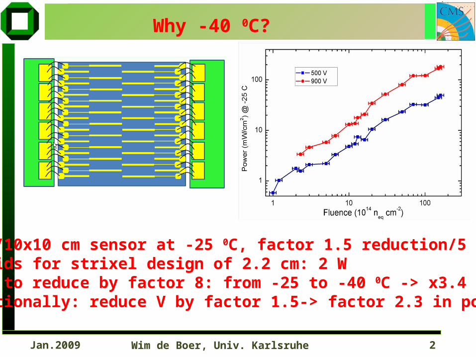
25 W/10x10 cm sensor at -25 0C, factor 1.5 reduction/5 0CHybrids for strixel design of 2.2 cm: 2 WWant to reduce by factor 8: from -25 to -40 0C -> x3.4Additionally: reduce V by factor 1.5-> factor 2.3 in power=VxI
Why -40 0C?
Wim de Boer, Univ. Karlsruhe 3Jan.2009
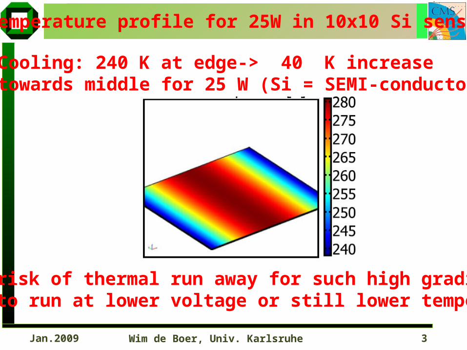
Temperature profile for 25W in 10x10 Si sensor
Cooling: 240 K at edge-> 40 K increase towards middle for 25 W (Si = SEMI-conductor!)
High risk of thermal run away for such high gradients !Have to run at lower voltage or still lower temperature.
Wim de Boer, Univ. Karlsruhe 4Jan.2009
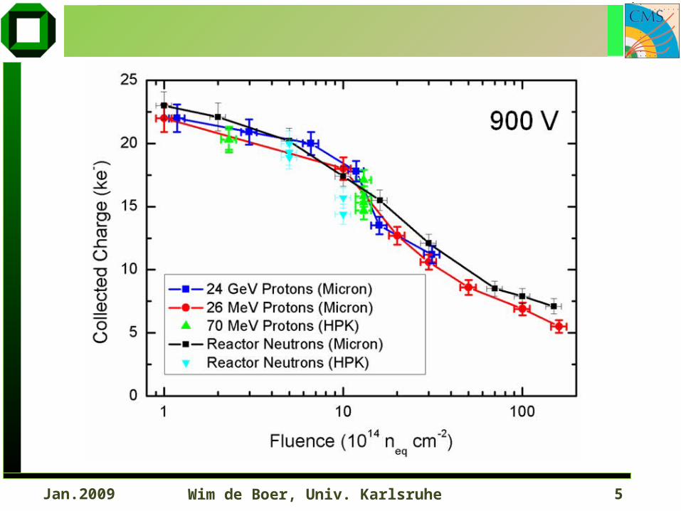
Wim de Boer, Univ. Karlsruhe 5Jan.2009
Wim de Boer, Univ. Karlsruhe 6Jan.2009
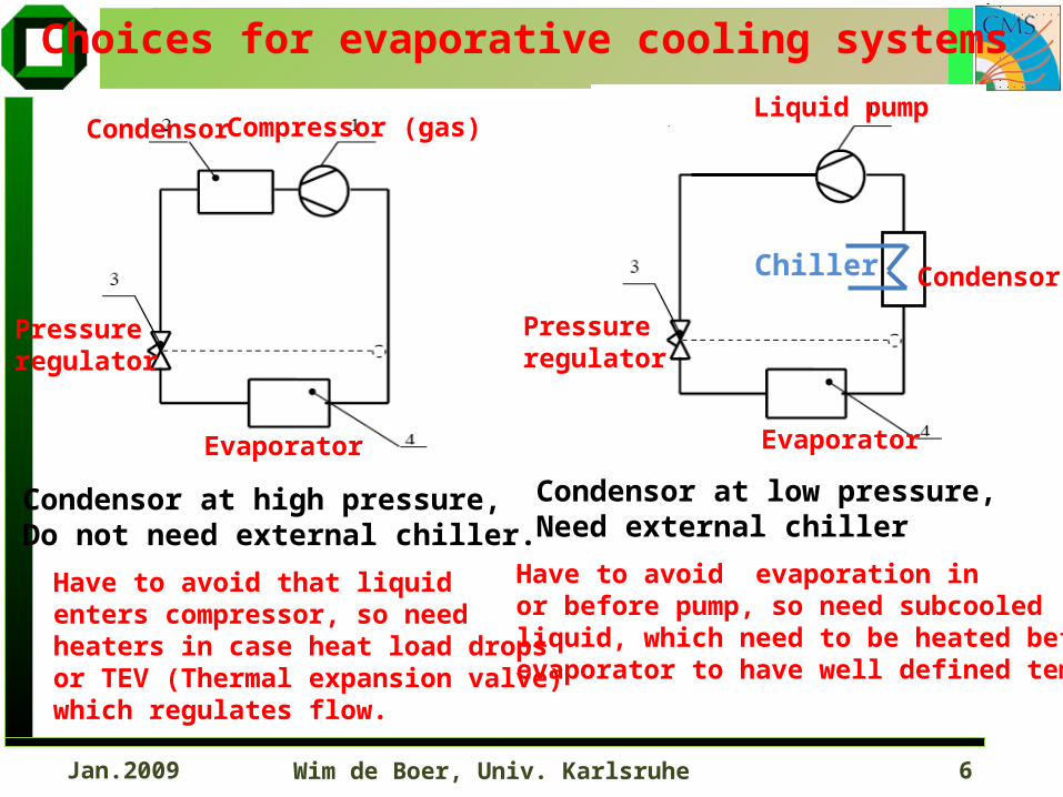
Choices for evaporative cooling systems
Compressor (gas)Condensor
Evaporator
Pressureregulator
Condensor at high pressure,Do not need external chiller.
Have to avoid that liquidenters compressor, so needheaters in case heat load dropsor TEV (Thermal expansion valve)which regulates flow.
Condensor at low pressure,Need external chiller
Have to avoid evaporation inor before pump, so need subcooledliquid, which need to be heated beforeevaporator to have well defined temp.
Liquid pump
Evaporator
Condensor
Pressureregulator
Chiller
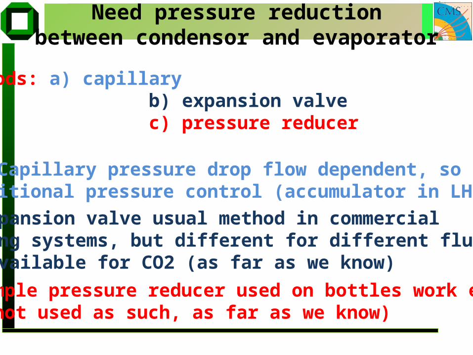
Need pressure reductionbetween condensor and evaporator
3 methods: a) capillary b) expansion valve c) pressure reducer
a) Capillary pressure drop flow dependent, so needadditional pressure control (accumulator in LHC-b)
b) Expansion valve usual method in commercial cooling systems, but different for different fluids.Not available for CO2 (as far as we know)
c) Simple pressure reducer used on bottles work excellent(but not used as such, as far as we know)
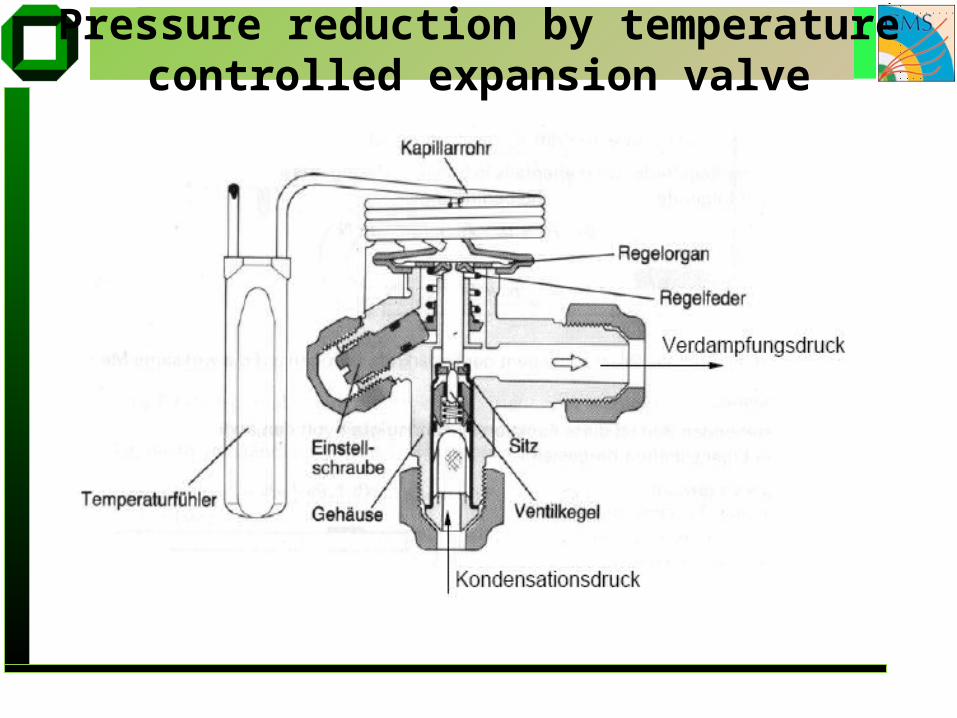
Pressure reduction by temperaturecontrolled expansion valve
Wim de Boer, Univ. Karlsruhe 9Jan.2009
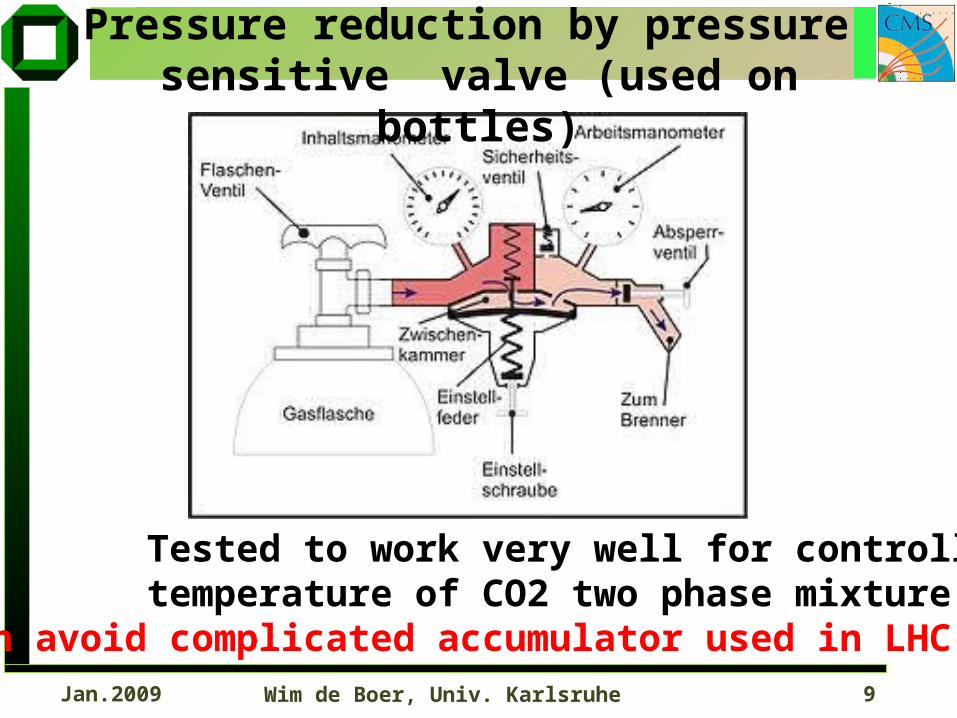
Pressure reduction by pressure sensitive valve (used on bottles)
Tested to work very well for controlling temperature of CO2 two phase mixture.Can avoid complicated accumulator used in LHC-b
Wim de Boer, Univ. Karlsruhe 10Jan.2009
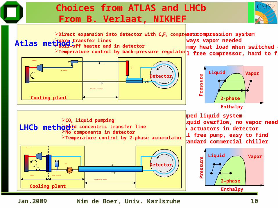
Choices from ATLAS and LHCbFrom B. Verlaat, NIKHEF
Liquid Vapor
2-phase
Pre
ssu
re
Enthalpy
Liquid Vapor
2-phase
Pre
ssu
re
Enthalpy
Vapor compression system•Always vapor needed•Dummy heat load when switched off•Oil free compressor, hard to find
Pumped liquid system•Liquid overflow, no vapor needed•No actuators in detector•Oil free pump, easy to find•Standard commercial chiller
Detector
Cooling plant
Warm transfer over distance
Detector
Cooling plant
Chiller Liquid circulation
Cold transfer over distance
Direct expansion into detector with C3F8 compressorWarm transfer linesBoil-off heater and in detectorTemperature control by back-pressure regulator
CO2 liquid pumpingCold concentric transfer lineNo components in detectorTemperature control by 2-phase accumulator
LHCb method:
Atlas method:
Hea
ter
Compressor
Pump
Compressor
BP. Regulator

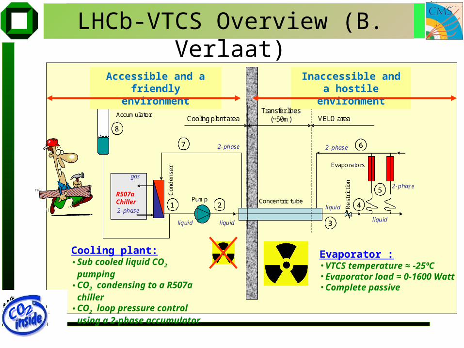
LHCb-VTCS Overview (B. Verlaat) A 2-Phase Accumulator Controlled Loop
2-phase
gas
R404a chiller
22
33
6677
11
88
44
2-phase2-phase
liquid liquid liquid
2-phase
Con
den
ser Evaporators
Concentric tubePump
Rest
rict
ion
AccumulatorCooling plant area
Transfer lines(~50m) VELO area
55
liquid
Evaporator :• VTCS temperature ≈ -25ºC• Evaporator load ≈ 0-1600 Watt• Complete passive
Cooling plant:• Sub cooled liquid CO2 pumping• CO2 condensing to a R507a
chiller• CO2 loop pressure control using
a 2-phase accumulator
Accessible and a friendly environment
Inaccessible and a hostile environment
R507aChiller
Wim de Boer, Univ. Karlsruhe 13Jan.2009
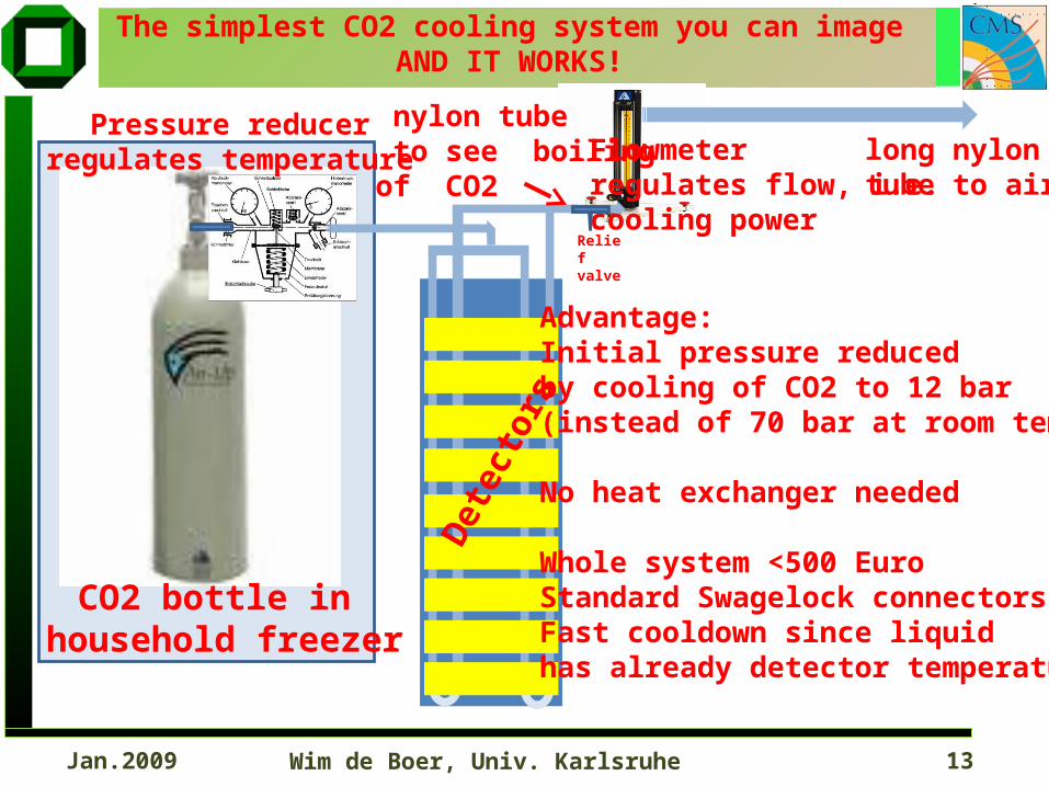
CO2 bottle in household freezer
Advantage:Initial pressure reduced by cooling of CO2 to 12 bar(instead of 70 bar at room temp)
No heat exchanger needed
Whole system <500 EuroStandard Swagelock connectorsFast cooldown since liquidhas already detector temperature
The simplest CO2 cooling system you can imageAND IT WORKS!
Det
ecto
rs
Flowmeterregulates flow, i.e.cooling power
Pressure reducerregulates temperature long nylon
tube to air
nylon tube to see boilingof CO2
Relief valve
Wim de Boer, Univ. Karlsruhe 14Jan.2009
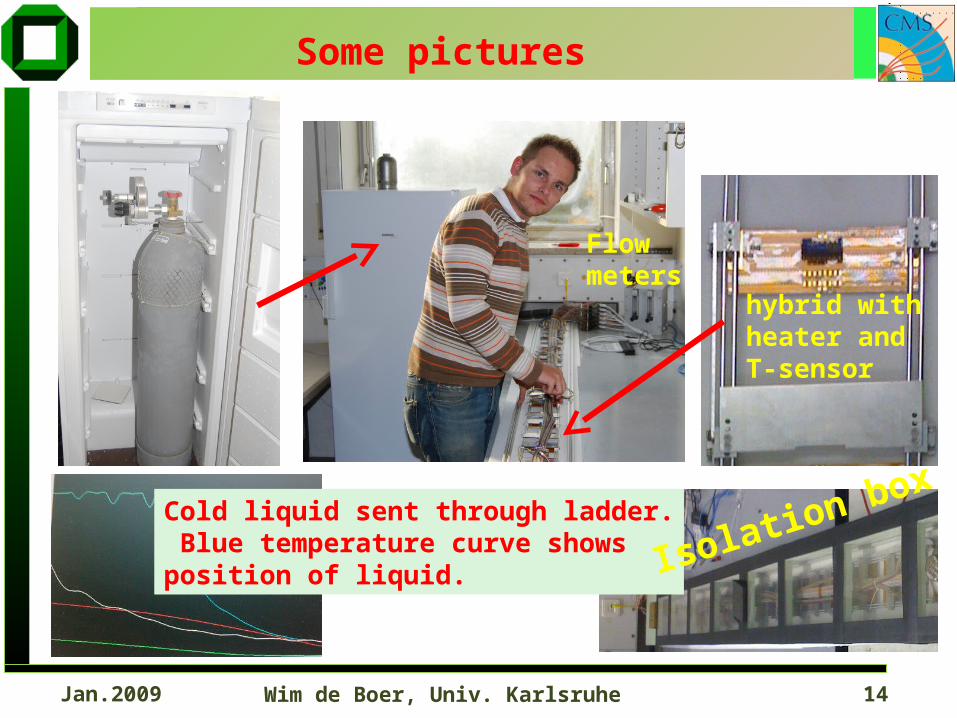
Flowmeters
hybrid withheater andT-sensor
Some pictures
Cold liquid sent through ladder. Blue temperature curve shows position of liquid.
Isolation box
Wim de Boer, Univ. Karlsruhe 15Jan.2009
-70
-60
-50
-40
-30
-20
-10
0
10
20
30
0 10 20 30 40 50 60
time [min]
tem
pera
ture
[°C
]
sensor1
sensor2
sensor4
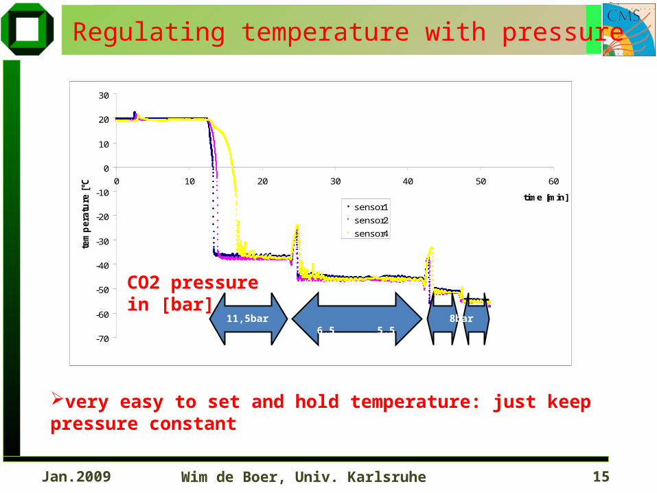
Regulating temperature with pressure
11,5bar 8bar 6,5 5,5
very easy to set and hold temperature: just keep pressure constant
CO2 pressurein [bar]
Wim de Boer, Univ. Karlsruhe 16Jan.2009
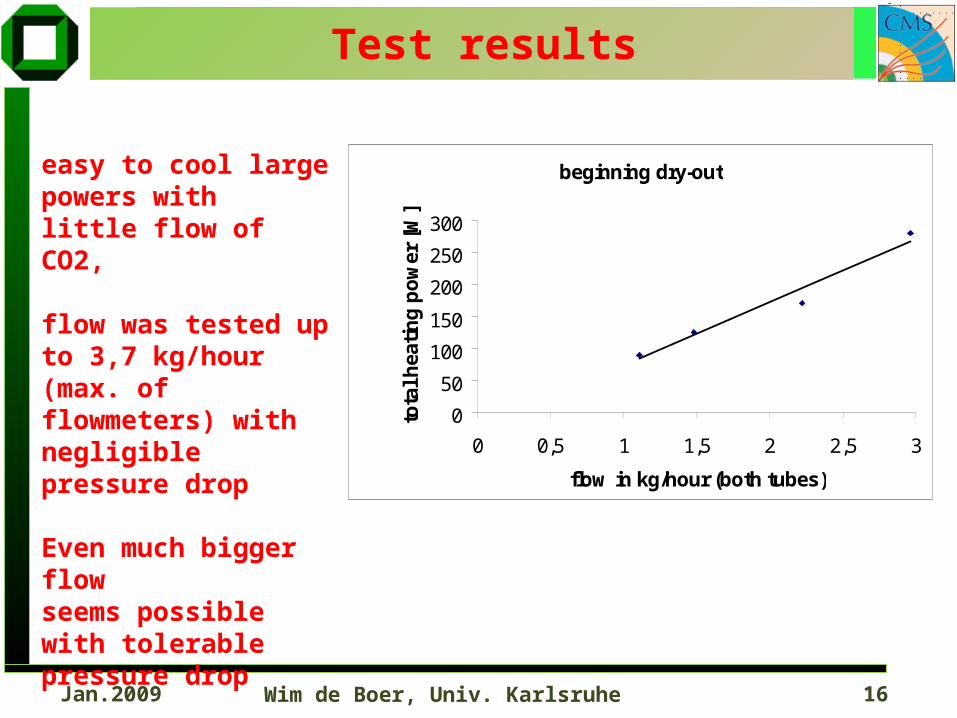
beginning dry-out
0
50
100
150
200
250
300
0 0,5 1 1,5 2 2,5 3
flow in kg/hour (both tubes)
tota
l hea
tin
g p
ow
er [
W]
Test results
easy to cool large powers with little flow of CO2,
flow was tested up to 3,7 kg/hour (max. of flowmeters) with negligible pressure drop
Even much bigger flow seems possible with tolerable pressure drop
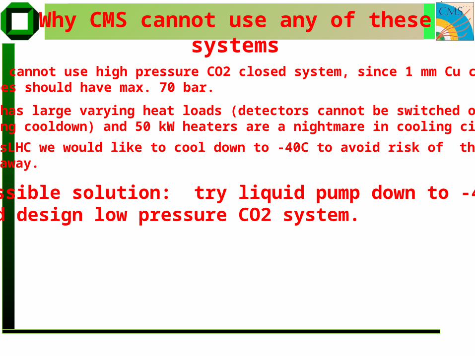
Why CMS cannot use any of these systems
CMS cannot use high pressure CO2 closed system, since 1 mm Cu coolingpipes should have max. 70 bar.
CMS has large varying heat loads (detectors cannot be switched onduring cooldown) and 50 kW heaters are a nightmare in cooling circuit
Possible solution: try liquid pump down to -40Cand design low pressure CO2 system.
For sLHC we would like to cool down to -40C to avoid risk of thermalrun away.
Wim de Boer, Univ. Karlsruhe 18Jan.2009
scale
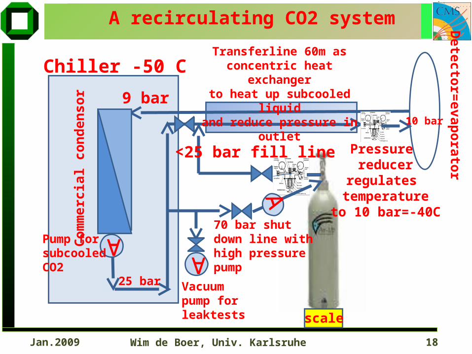
A recirculating CO2 system
Com
mer
cial
con
den
sor
Pressure reducer
regulates temperature
to 10 bar=-40C
Detector=
evaporator
9 bar
<25 bar fill line
Vacuumpump for leaktests
Chiller -50 C
Pump for subcooledCO2
Transferline 60m asconcentric heat exchangerto heat up subcooled liquid
and reduce pressure in outlet
70 bar shut down line withhigh pressurepump
10 bar
25 bar
Wim de Boer, Univ. Karlsruhe 19Jan.2009
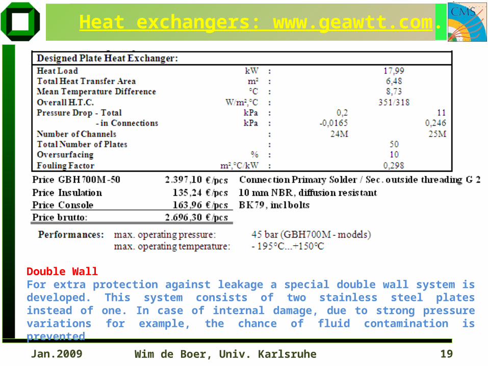
Heat exchangers: www.geawtt.com.
Double WallFor extra protection against leakage a special double wall system is developed. This system consists of two stainless steel plates instead of one. In case of internal damage, due to strong pressure variations for example, the chance of fluid contamination is prevented
Wim de Boer, Univ. Karlsruhe 20Jan.2009
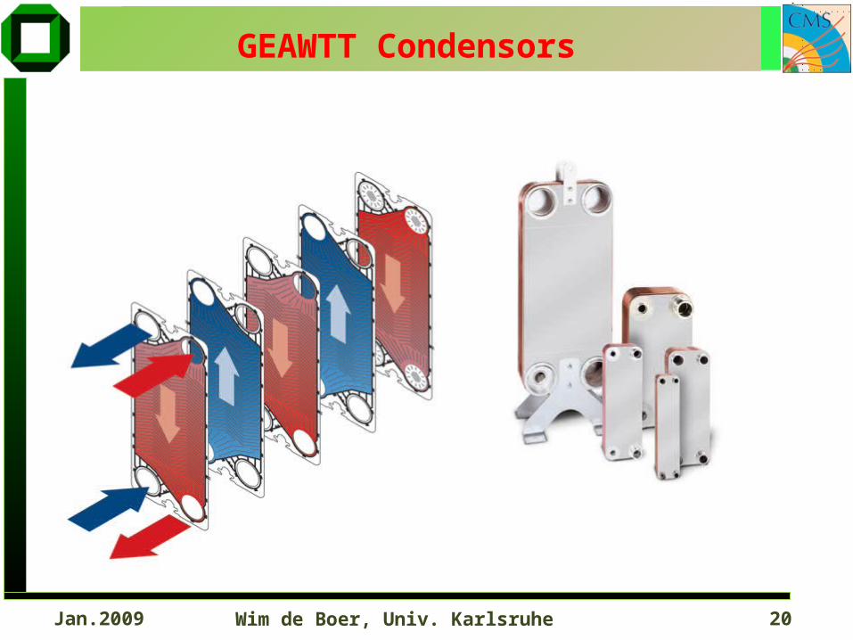
GEAWTT Condensors
Wim de Boer, Univ. Karlsruhe 21Jan.2009
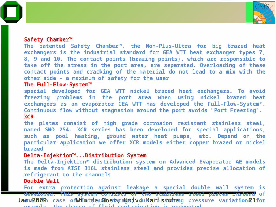
Safety Chamber™The patented Safety Chamber™, the Non-Plus-Ultra for big brazed heat exchangers is the industrial standard for GEA WTT heat exchanger types 7, 8, 9 and 10. The contact points (brazing points), which are responsible to take off the stress in the port area, are separated. Overloading of these contact points and cracking of the material do not lead to a mix with the other side - a maximum of safety for the userThe Full-Flow-System™special developed for GEA WTT nickel brazed heat exchangers. To avoid freezing problems in the port area when using nickel brazed heat exchangers as an evaporator GEA WTT has developed the Full-Flow-System™. Continuous flow without stagnation around the port avoids "Port Freezing".XCRthe plates consist of high grade corrosion resistant stainless steel, named SMO 254. XCR series has been developed for special applications, such as pool heating, ground water heat pumps, etc. Depend on the particular application we offer XCR models either copper brazed or nickel brazedDelta-Injektion™...Distribution SystemThe Delta-Injektion™ distribution system on Advanced Evaporator AE models is made from AISI 316L stainless steel and provides precise allocation of refrigerant to the channelsDouble WallFor extra protection against leakage a special double wall system is developed. This system consists of two stainless steel plates instead of one. In case of internal damage, due to strong pressure variations for example, the chance of fluid contamination is prevented.
Wim de Boer, Univ. Karlsruhe 22Jan.2009
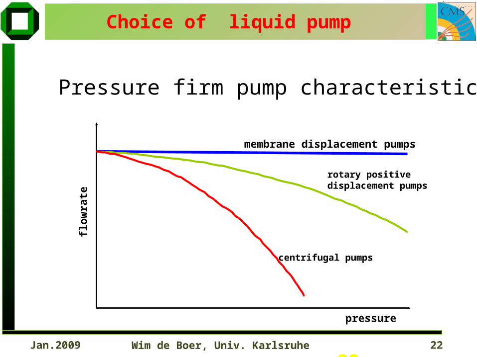
Choice of liquid pump
Pressure firm pump characteristic
22
flow
rate
pressure
membrane displacement pumps
rotary positive displacement pumps
centrifugal pumps
Wim de Boer, Univ. Karlsruhe 23Jan.2009
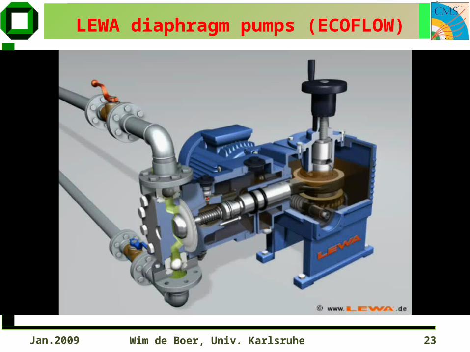
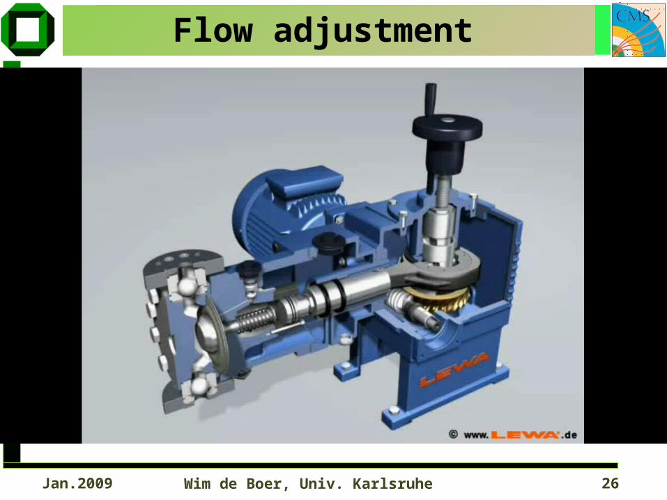
LEWA diaphragm pumps (ECOFLOW)
Wim de Boer, Univ. Karlsruhe 24Jan.2009
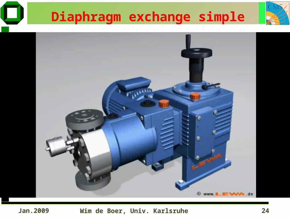
Diaphragm exchange simple
Wim de Boer, Univ. Karlsruhe 25Jan.2009
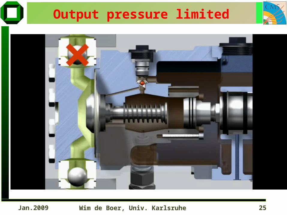
Output pressure limited
Wim de Boer, Univ. Karlsruhe 26Jan.2009
Flow adjustment
Wim de Boer, Univ. Karlsruhe 27Jan.2009
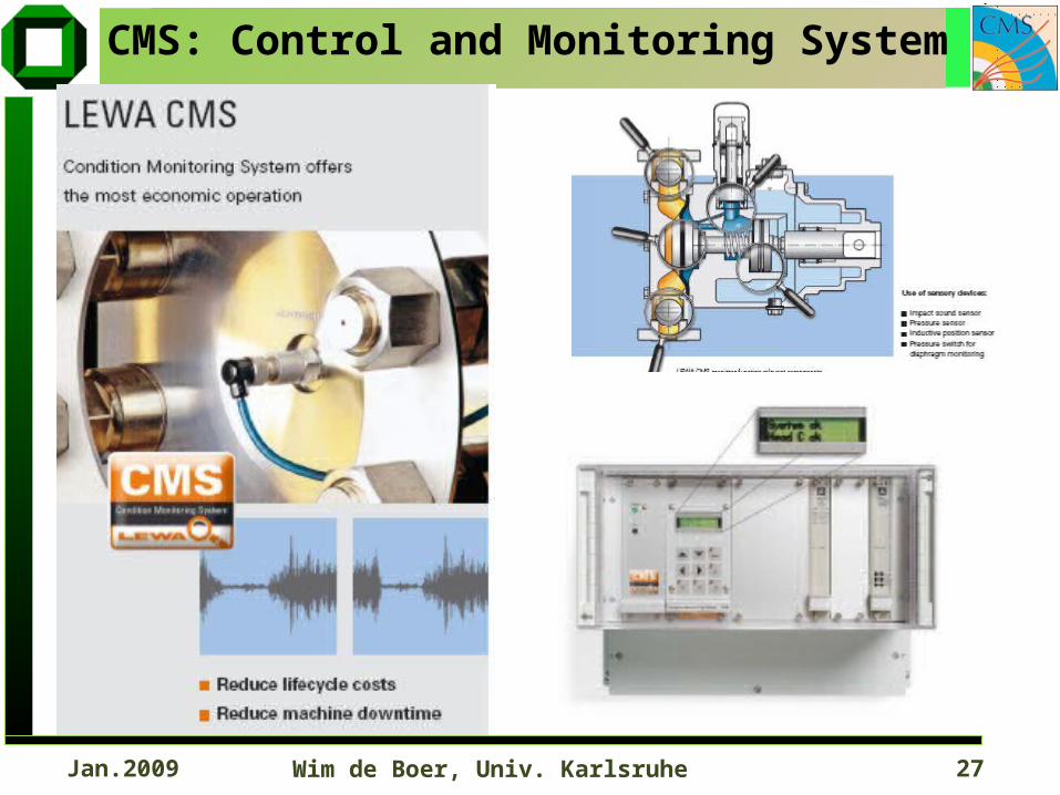
CMS: Control and Monitoring System
Wim de Boer, Univ. Karlsruhe 28Jan.2009
frequency n
fow
rate
Q
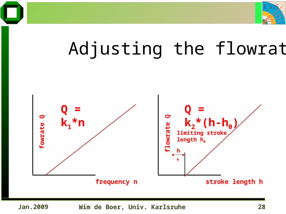
Q = k1*n
stroke length h
flow
rate
Q
Q = k2*(h-h0)
h
0
limiting stroke length h0
Adjusting the flowrate
Wim de Boer, Univ. Karlsruhe 29Jan.2009
Vh Vh Vh
time t
Flo
wra
te Q
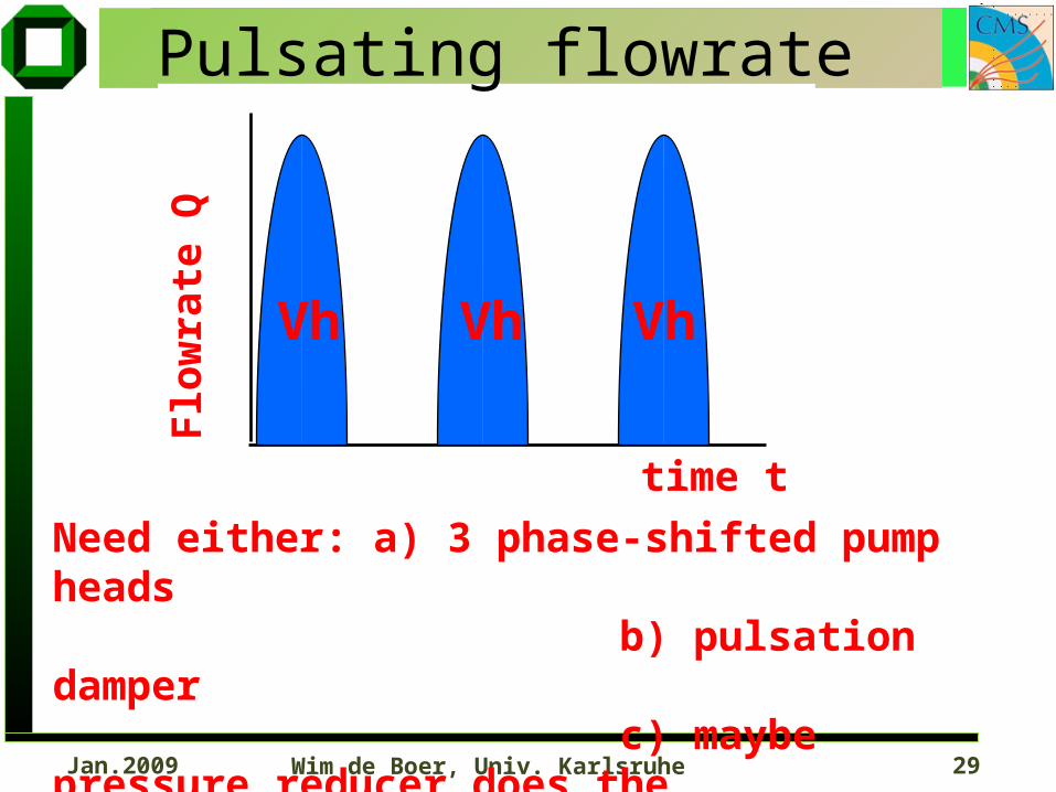
Pulsating flowrate
Need either: a) 3 phase-shifted pump heads b) pulsation damper c) maybe pressure reducer does the job to prevent temperature variations
Wim de Boer, Univ. Karlsruhe 30Jan.2009
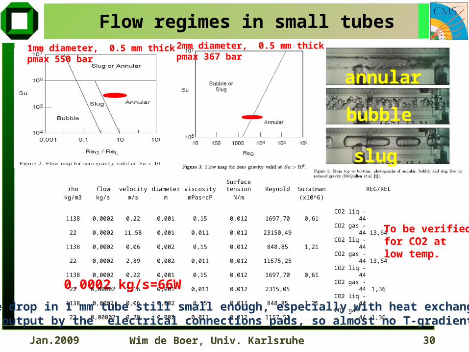
1mm diameter, 0.5 mm thick pmax 550 bar
2mm diameter, 0.5 mm thick pmax 367 bar
Flow regimes in small tubes
0.0002 kg/s=66W
rho flow velocity diameter viscosity Surface tension Reynold SuratmanREG/REL
kg/m3 kg/s m/s m mPas=cP N/m (x10^6)
1138 0,0002 0,22 0,001 0,15 0,012 1697,70 0,61 CO2 liq -44
22 0,0002 11,58 0,001 0,011 0,012 23150,49 CO2 gas -44 13,64
1138 0,0002 0,06 0,002 0,15 0,012 848,85 1,21 CO2 liq -44
22 0,0002 2,89 0,002 0,011 0,012 11575,25 CO2 gas -44 13,64
1138 0,0002 0,22 0,001 0,15 0,012 1697,70 0,61 CO2 liq -44
22 0,00002 1,16 0,001 0,011 0,012 2315,05 CO2 gas -44 1,36
1138 0,0002 0,06 0,002 0,15 0,012 848,85 1,21 CO2 liq -44
22 0,00002 0,29 0,002 0,011 0,012 1157,52 CO2 gas -44 1,36
Pressure drop in 1 mm tube still small enough, especially with heat exchange betweenin- and output by the electrical connections pads, so almost no T-gradient on ladder
To be verifiedfor CO2 atlow temp.
annular
bubble
slug
Wim de Boer, Univ. Karlsruhe 31Jan.2009
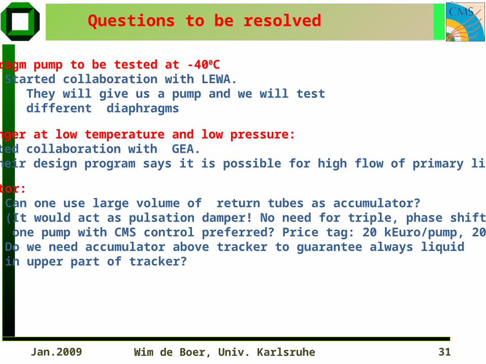
Questions to be resolved
Diaphragm pump to be tested at -400C Started collaboration with LEWA. They will give us a pump and we will test different diaphragms
Heat exchanger at low temperature and low pressure: Started collaboration with GEA. Their design program says it is possible for high flow of primary liquid
Accumulator: Can one use large volume of return tubes as accumulator? (It would act as pulsation damper! No need for triple, phase shifted pumps, one pump with CMS control preferred? Price tag: 20 kEuro/pump, 20 kEuro/CMS) Do we need accumulator above tracker to guarantee always liquid in upper part of tracker?
Wim de Boer, Univ. Karlsruhe 32Jan.2009
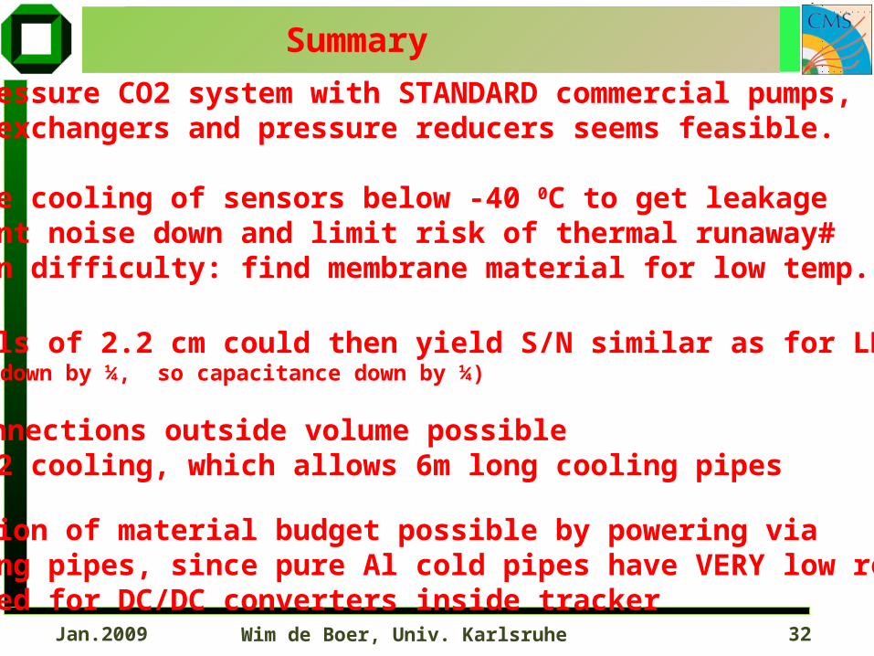
Summary
• low pressure CO2 system with STANDARD commercial pumps, heat exchangers and pressure reducers seems feasible.
• Require cooling of sensors below -40 0C to get leakage current noise down and limit risk of thermal runaway# (main difficulty: find membrane material for low temp.)
• Strixels of 2.2 cm could then yield S/N similar as for LHC (signal down by ¼, so capacitance down by ¼)
• All connections outside volume possible by CO2 cooling, which allows 6m long cooling pipes
• Reduction of material budget possible by powering via cooling pipes, since pure Al cold pipes have VERY low resistivity. No need for DC/DC converters inside tracker
Wim de Boer, Univ. Karlsruhe 33Jan.2009
Backup slides
Wim de Boer, Univ. Karlsruhe 34Jan.2009
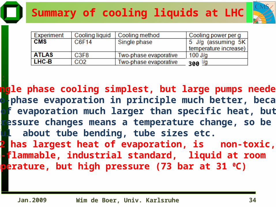
Summary of cooling liquids at LHC
Notes: Single phase cooling simplest, but large pumps needed Two-phase evaporation in principle much better, becauseheat of evaporation much larger than specific heat, butany pressure changes means a temperature change, so be careful about tube bending, tube sizes etc. CO2 has largest heat of evaporation, is non-toxic, non-flammable, industrial standard, liquid at room temperature, but high pressure (73 bar at 31 0C)
300
Wim de Boer, Univ. Karlsruhe 35Jan.2009
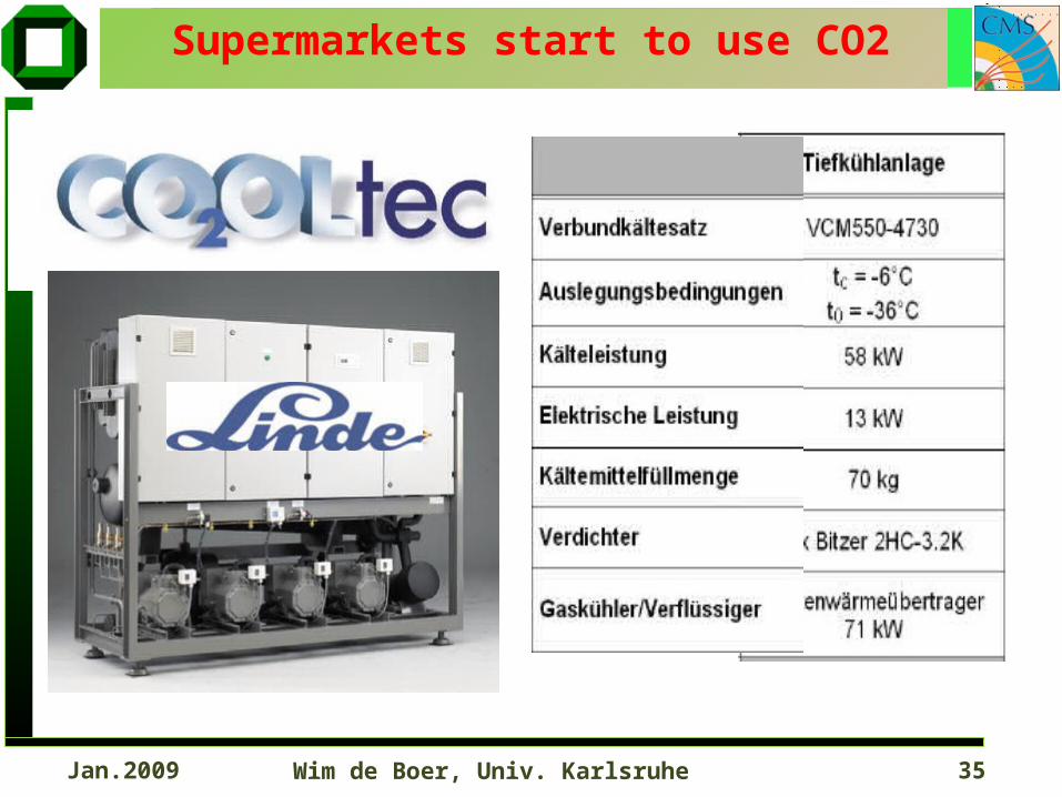
Supermarkets start to use CO2
Wim de Boer, Univ. Karlsruhe 36Jan.2009
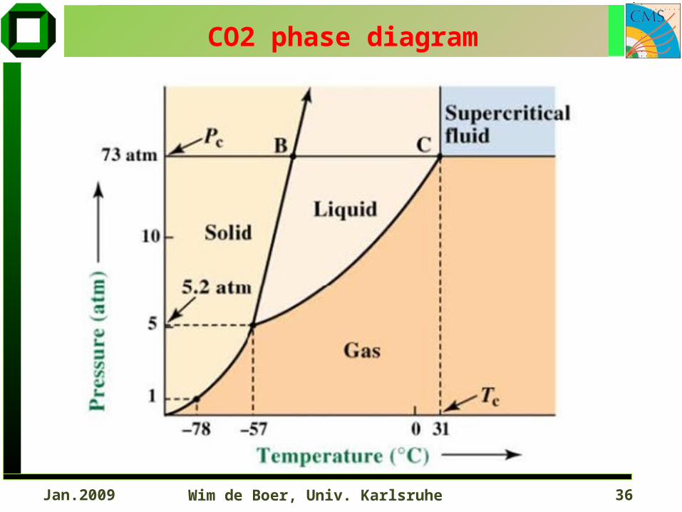
CO2 phase diagram