Embed Size (px)
Citation preview
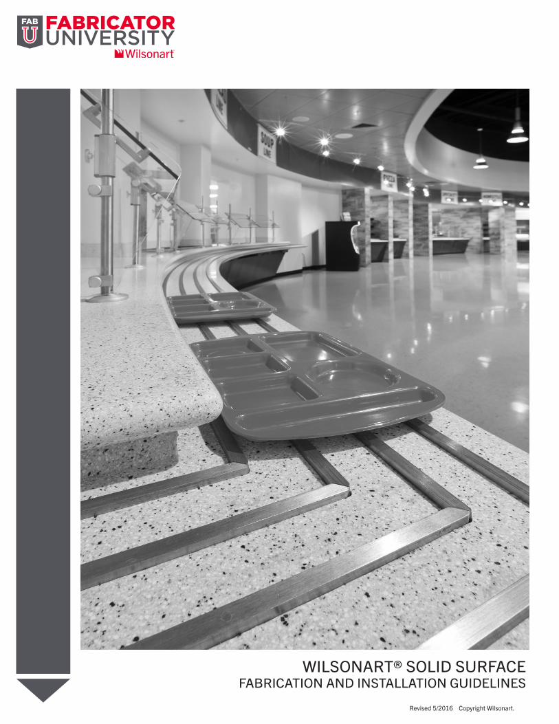
WILSONART® SOLID SURFACE FABRICATION AND INSTALLATION GUIDELINES
Revised 5/2016 Copyright Wilsonart.
CONTENTS
CHAPTER I PRODUCT INFORMATION 2
CHAPTER II GENERAL SAFETY 3
CHAPTER III MATERIAL HANDLING 4
CHAPTER IV INSPECTION 6
CHAPTER V TOOLING 7
CHAPTER VI ADHESIVES 8
CHAPTER VII COUNTERTOP LAYOUT & MEASURING 9
CHAPTER VIII FABRICATION 10
CHAPTER IX COMMERCIAL HOT/COLD WELL CUTOUTS 14
CHAPTER X BACKSPLASH 15
CHAPTER XI FINISHING 16
CHAPTER XII INSTALLATION 17
CHAPTER XIII CARE & MAINTENANCE 19
Introduction 3
Safety/Precautions 4
Handling/Storage 5
Tools 6
Job Planning 10
Deck Seams 16
Drop Edges 21
Sinks 25
Cutouts 27
Conventional & Cove Backsplash 29
Thermoforming 31
Finishing 32
Installation 34
3
INTRODUCTION
Any fabrication procedure or technique not contained within the Wilsonart®
Solid Surface Fabrication Manual will not be recognized by Wilsonart LLC as
an approved method of fabrication. Deviations from these techniques must be
approved in writing by a Wilsonart Representative.
CHAPTER I
4
SAFETY
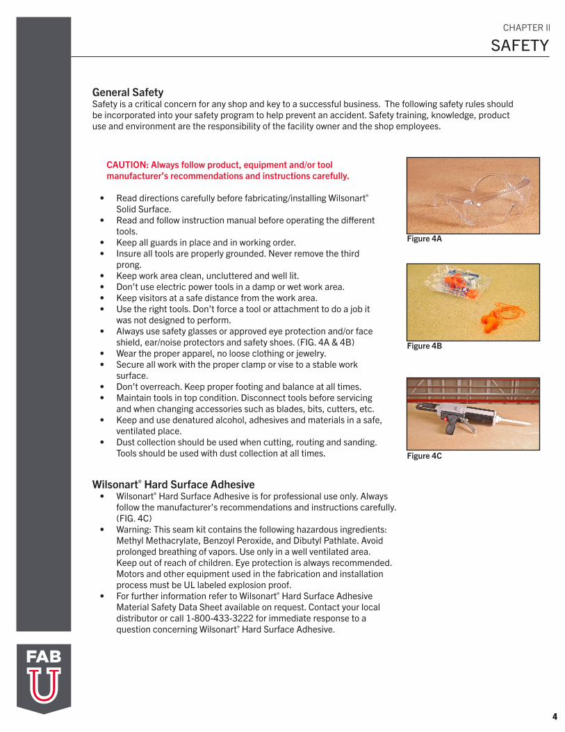
Figure 4A
Figure 4B
General SafetySafety is a critical concern for any shop and key to a successful business. The following safety rules should be incorporated into your safety program to help prevent an accident. Safety training, knowledge, product use and environment are the responsibility of the facility owner and the shop employees.
CAUTION: Always follow product, equipment and/or tool manufacturer’s recommendations and instructions carefully.
• Read directions carefully before fabricating/installing Wilsonart®
Solid Surface.• Read and follow instruction manual before operating the different
tools.• Keep all guards in place and in working order.• Insure all tools are properly grounded. Never remove the third
prong.• Keep work area clean, uncluttered and well lit. • Don’t use electric power tools in a damp or wet work area.• Keep visitors at a safe distance from the work area.• Use the right tools. Don’t force a tool or attachment to do a job it
was not designed to perform.• Always use safety glasses or approved eye protection and/or face
shield, ear/noise protectors and safety shoes. (FIG. 4A & 4B)• Wear the proper apparel, no loose clothing or jewelry.• Secure all work with the proper clamp or vise to a stable work
surface. • Don’t overreach. Keep proper footing and balance at all times.• Maintain tools in top condition. Disconnect tools before servicing
and when changing accessories such as blades, bits, cutters, etc.• Keep and use denatured alcohol, adhesives and materials in a safe,
ventilated place.• Dust collection should be used when cutting, routing and sanding.
Tools should be used with dust collection at all times.
Wilsonart® Hard Surface Adhesive• Wilsonart® Hard Surface Adhesive is for professional use only. Always
follow the manufacturer’s recommendations and instructions carefully. (FIG. 4C)
• Warning: This seam kit contains the following hazardous ingredients:Methyl Methacrylate, Benzoyl Peroxide, and Dibutyl Pathlate. Avoidprolonged breathing of vapors. Use only in a well ventilated area. Keep out of reach of children. Eye protection is always recommended. Motors and other equipment used in the fabrication and installationprocess must be UL labeled explosion proof.
• For further information refer to Wilsonart® Hard Surface AdhesiveMaterial Safety Data Sheet available on request. Contact your localdistributor or call 1-800-433-3222 for immediate response to aquestion concerning Wilsonart® Hard Surface Adhesive.
Figure 4C
CHAPTER Il
5
HANDLING
HANDLING: Carry Wilsonart® Solid Surface sheets vertically to minimize flexing.
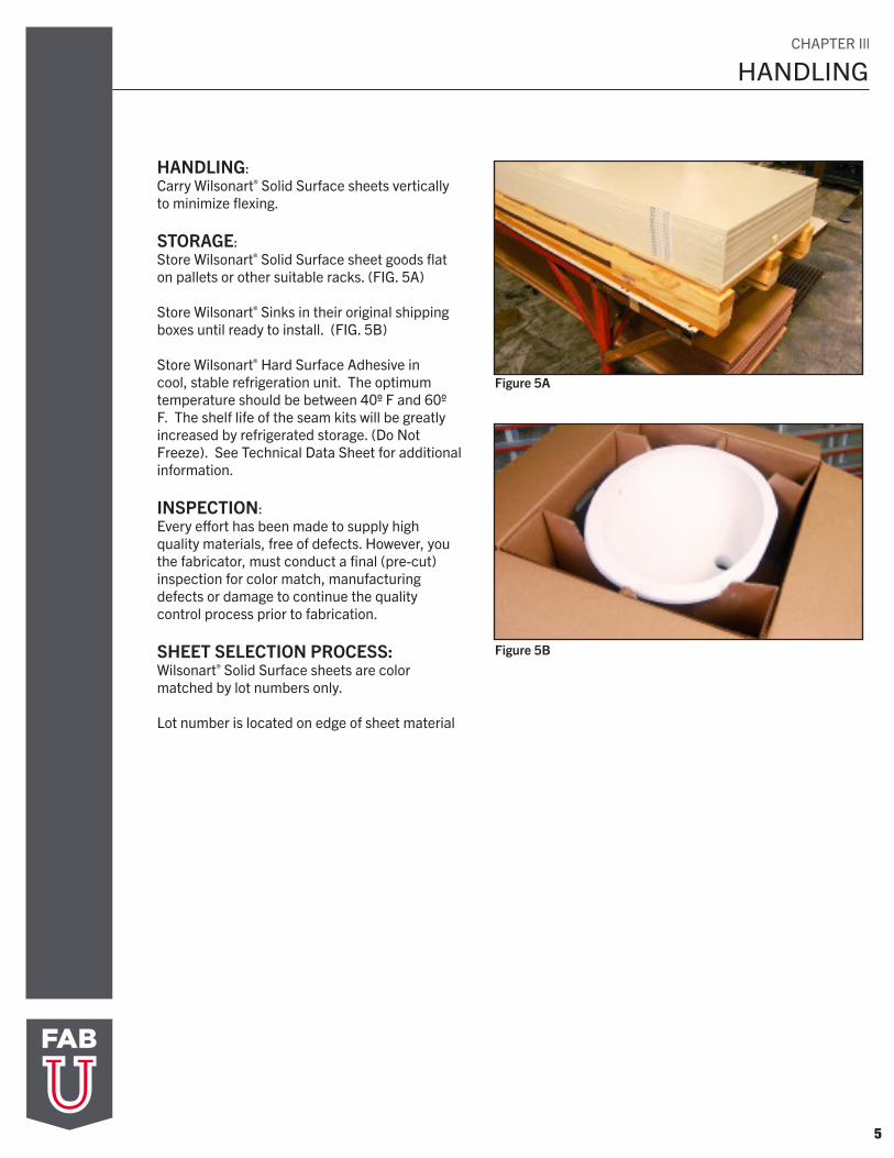
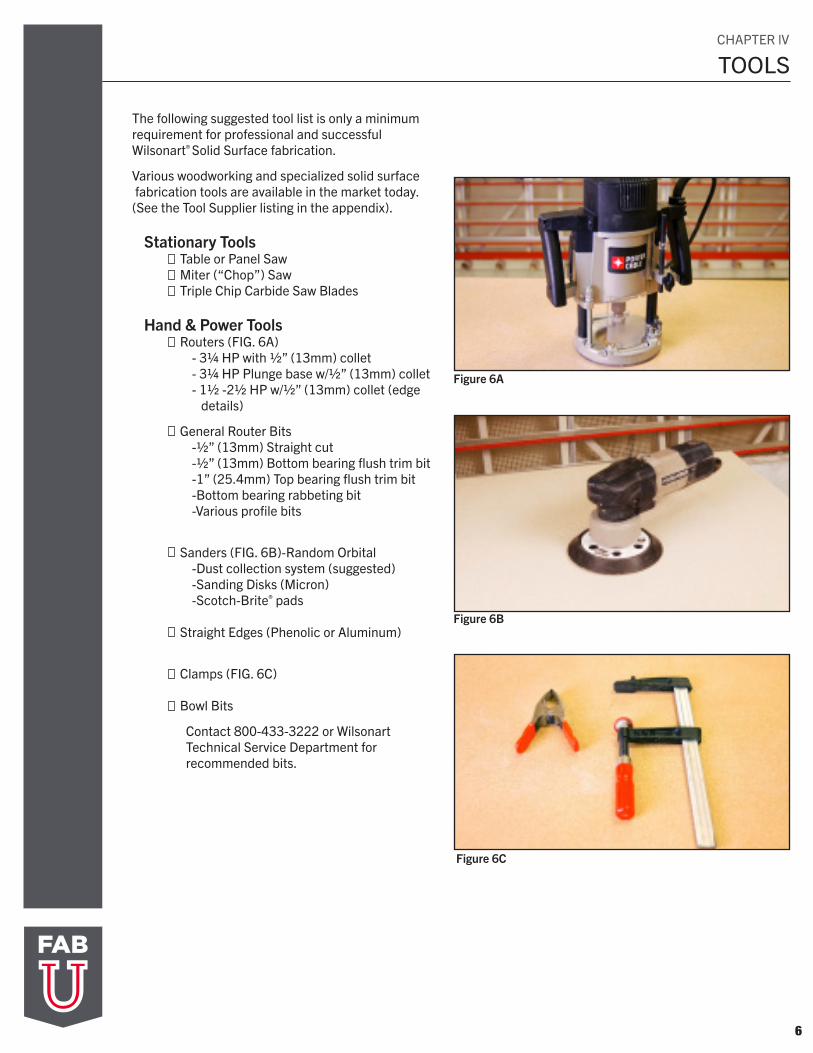
STORAGE: Store Wilsonart® Solid Surface sheet goods flat on pallets or other suitable racks. (FIG. 5A) Store Wilsonart® Sinks in their original shipping boxes until ready to install. (FIG. 5B) Store Wilsonart® Hard Surface Adhesive in cool, stable refrigeration unit. The optimum temperature should be between 40º F and 60º F. The shelf life of the seam kits will be greatly increased by refrigerated storage. (Do Not Freeze). See Technical Data Sheet for additional information.
INSPECTION: Every effort has been made to supply high quality materials, free of defects. However, you the fabricator, must conduct a final (pre-cut) inspection for color match, manufacturing defects or damage to continue the quality control process prior to fabrication.
SHEET SELECTION PROCESS: Wilsonart® Solid Surface sheets are color matched by lot numbers only.
Lot number is located on edge of sheet material
Figure 5A
Figure 5B
CHAPTER Ill
6
TOOLS
The following suggested tool list is only a minimum requirement for professional and successful Wilsonart® Solid Surface fabrication.
Various woodworking and specialized solid surface fabrication tools are available in the market today. (See the Tool Supplier listing in the appendix).
Stationary Tools Table or Panel Saw Miter (“Chop”) Saw Triple Chip Carbide Saw Blades
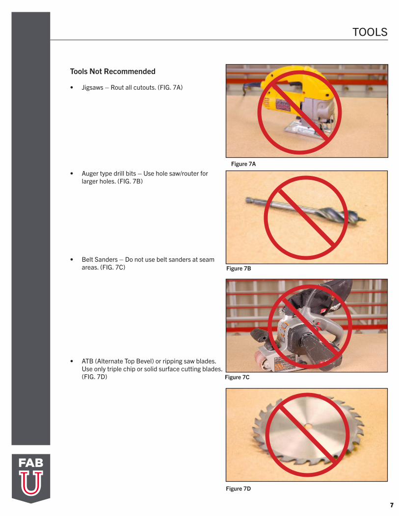
Hand & Power Tools Routers (FIG. 6A) - 3¼ HP with ½” (13mm) collet - 3¼ HP Plunge base w/½” (13mm) collet - 1½ -2½ HP w/½” (13mm) collet (edge details)
General Router Bits -½” (13mm) Straight cut -½” (13mm) Bottom bearing flush trim bit -1” (25.4mm) Top bearing flush trim bit -Bottom bearing rabbeting bit -Various profile bits
Sanders (FIG. 6B)-Random Orbital -Dust collection system (suggested) -Sanding Disks (Micron) -Scotch-Brite® pads Straight Edges (Phenolic or Aluminum)
Clamps (FIG. 6C) Bowl Bits
Contact 800-433-3222 or Wilsonart Technical Service Department for recommended bits.
Figure 6A
Figure 6B
Figure 6C
CHAPTER lV
7
TOOLS
Tools Not Recommended
• Jigsaws – Rout all cutouts. (FIG. 7A)
• Auger type drill bits – Use hole saw/router forlarger holes. (FIG. 7B)
• Belt Sanders – Do not use belt sanders at seamareas. (FIG. 7C)
• ATB (Alternate Top Bevel) or ripping saw blades. Use only triple chip or solid surface cutting blades.(FIG. 7D)
Figure 7A
Figure 7B
Figure 7C
Figure 7D
8
TOOL MANUFACTURERS
Stationary Tools• Powermatic 1-800-274-6848 www.powermatic.com
• Delta 1-800-223-7278 www.detlamachinery.com
• Holz Her 1-704-587-3400 www.holzher.com
• Striebig 1-781-585-4364 www.csaw.com
Hand Tools - Routers, Sanders, Bits, etc.• Porter Cable 1-888-848-5175 www.portercable.com
• Beaver Tools 1-800-365-6677 www.beavertools.com
Router Bits• Amana Tool 1-800-445-0077 www.amanatool.com
• Velepec 1-800-365-6636 www.velepectools.com
• Wesley Tools, Ltd. 1-800-397-6867 www.wesleytools.com
Sanding Equipment
• Fein 1-800-441-9878 www.feinus.com
• Festool 1-800-423-3531 www.festoolusa.com
• Surcare 1-800-669-5519 www.surcare.com
• Gem Sander 1-800-447-4436 www.gem-industries.com
• Dynabrade 1-716-631-0100 www.dyabrade.com
• Master Power 1-866-557-8316 www.masterpneumatictools.com
Sandpaper / Finishing Pads
• 3M 1-800-742-9546 Scotch-Brite & Trizact www.3m.com
• Micro Mesh 1-908-788-5550 www.sisweb.com
• Norton 1-800-446-1119 www.nortonabrasives.com
• Mirka 1-800-843-3904 www.mirka-usa.com
• Sia 1-800-459-3534 www.sia-abrasives.com
Pipe and Bar Clamps
• Bessey 1-800-828-1004 www.americanclamping.com
9
TOOL MANUFACTURERS
Recommended Saw Blades
• Amana 1-800-445-0077 www.amanatool.com
• DML 1-800-242-7003 www.dmlwoodworking.com
• FS Tool 1-800-387-9723 www.fstoolcorp.com
Misc. Tools
• Fein Power Tools 1-800-441-9878 www.feinus.com Dustless sanding system
• The Pinske Edge 1-800-874-6753 www.pinske-edge.com Specialized solid surfacing tools
• Specialty Tools 1-800-669-5519 www.specialtytools.com • Perfect Seam 1-770-463-8321 Vacuum base seam clamps Vacuum base seam leveler www.omnicubed.com
• Wood’s Power Grip Co. 1-800-548-7341 Vacuum base seam clamps www.powergrip.com
• Conprotec Inc. 1-603-893-2727 www.mixpac.com Adhesive despenser repair parts
• Betterley Industries 1-800-871-7516 www.betterleytools.com
• Align-Rite Tool Co. 1-888-624-1942 www.alignritetool.com Fabrication tools
• A.M.P.S. 1-800-669-5519 www.ampsedge.com Straight edge
• DeWalt 1-800-433-9258 www.dewalt.com
• Zip Wall 1-800-718-2255 www.zipwall.com Dust containment
• Sink Setter at Precision Works 1-714-847-3396 Sinksetter, Inc. Sink Setter Brackets Easy Leveling Shelf and Counter Bracket www.sinkset.com
• Guhdo 1-800-544-8436 www.guhdo.com
• Forrest 1-800-733-7111 www.forrestsawblades.com
• Leitz 1-800-253-6070 www.leitz.com

10
JOB PLANNING
FAB TIPS
• Do not use lacquer thinner, acetone or other solvents on Wilsonart Solid Surface material.
• Colored or printed towels can leave a residue which will contaminate the seam material and cause a weak or stained bond line.
• Refer to the Thermoforming Section when forming or bending Wilsonart Solid Surface. Wilsonart Cityscape, Cosmic and Ice Collections are not recommended or approved for Thermoforming process. Spot heating or cold bending is not approved and will introduce internal stress into the product.
• Thermoforming is not recommended or approved by Wilsonart for the Cityscape, Cosmic and Ice Collections. Please contact Wilsonart Technical Service Group at 800-433-3222 for further information.
• All edges should be sanded smooth and free of sharp corners and kerf marks which result in stress points.
CHAPTER V
11
JOB PLANNING
Wilsonart Solid Surface Countertop Layout Conventional Seams Locations
Figure 11A
Seam
Sea
m
Seam
Sea
m
Ove
rhan
g
Dishwasher
Coo
ktop
Offset Seamsat least 1" (25.4 mm) from corners
Place Seams nocloser than 3" (76.2 mm)from any cooktop cutout
or dishwasher
Radius allinside corners minimum
1/2" (13 mm)
3" min(76.2 mm)
Radius allcutout corners minimum
1/4" (6.4 mm)
JOB PLANNING
12
Seam
ButtSeam
But
t Sea
m
Sea
m
Ove
rhan
g
Minimum 1/2" (12.7 mm)inside corner radius required
See Corner BlockRequirements Below
Place Seams nocloser than 3" (76.2 mm)from any cooktop cutout
or dishwasher
3" min(76.2 mm)
Coo
ktop Radius all
cutout corners minimum1/4" (6.4 mm)
Dishwasher
3" min(76.2 mm)
Figure 12A
Wilsonart Solid Surface Countertop Layout PT Seams Locations
JOB PLANNING
13
Seam
45° Miter Seam
Sea
m
Ove
rhan
g
45° Corner Seam
Place Seams nocloser than 3" (76.2 mm)from any cooktop cutout
or dishwasher
Radius allinside corners minimum
1/2" (13 mm)
3" min(76.2 mm) Island
Con
vent
iona
l Sea
m
Design Movement
Radius allcutout corners minimum
1/4" (6.4 mm)
45° M
iter S
eam
Coo
ktop
Dishwasher
3" min(76.2 mm)
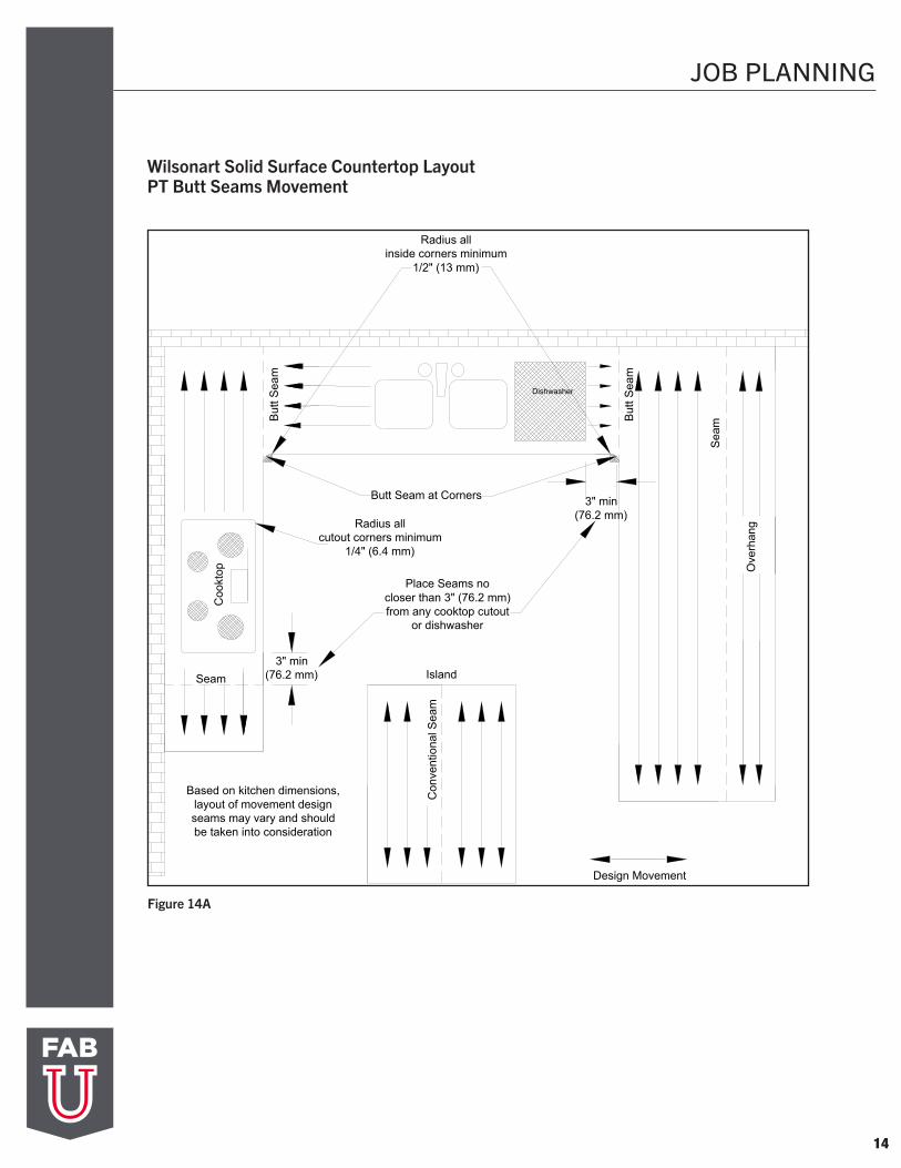
Based on kitchen dimensions,layout of movement designseams may vary and shouldbe taken into consideration
Figure 13A
Wilsonart Solid Surface Countertop Layout 45˚ Seams Locations
JOB PLANNING
14
Seam
But
t Sea
m
Sea
m
Ove
rhan
g
Place Seams nocloser than 3" (76.2 mm)from any cooktop cutout
or dishwasher
Radius allinside corners minimum
1/2" (13 mm)
3" min(76.2 mm) Island
Con
vent
iona
l Sea
m
Design Movement
But
t Sea
m
Butt Seam at Corners
Coo
ktop
Radius allcutout corners minimum
1/4" (6.4 mm)
Based on kitchen dimensions,layout of movement designseams may vary and shouldbe taken into consideration
Dishwasher
3" min(76.2 mm)
Figure 14A
Wilsonart Solid Surface Countertop Layout PT Butt Seams Movement
JOB PLANNING
15
Seam
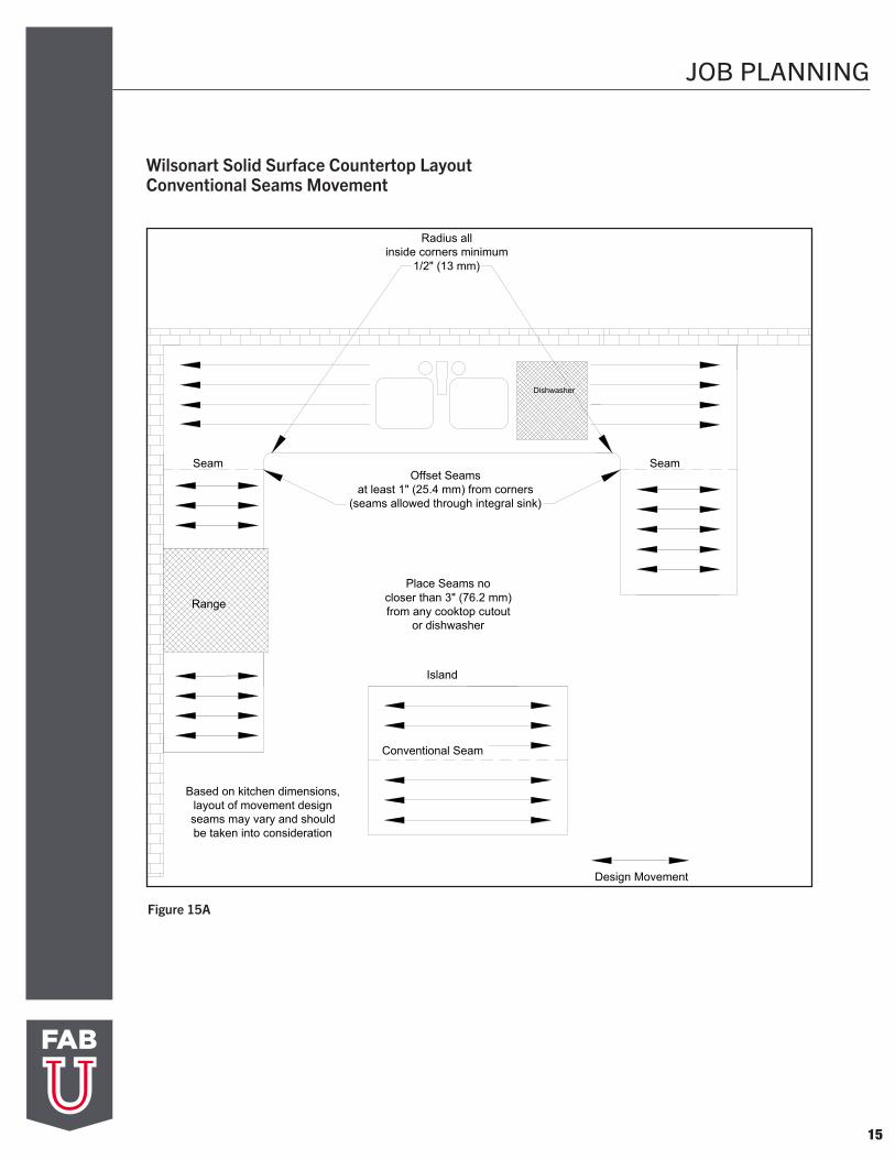
Radius allinside corners minimum
1/2" (13 mm)
Island
Conventional Seam
Design Movement
Offset Seamsat least 1" (25.4 mm) from corners
(seams allowed through integral sink)
Seam
Range
Place Seams nocloser than 3" (76.2 mm)from any cooktop cutout
or dishwasher
Based on kitchen dimensions,layout of movement designseams may vary and shouldbe taken into consideration
Dishwasher
Figure 15A
Wilsonart Solid Surface Countertop Layout Conventional Seams Movement
16
DECK SEAMS
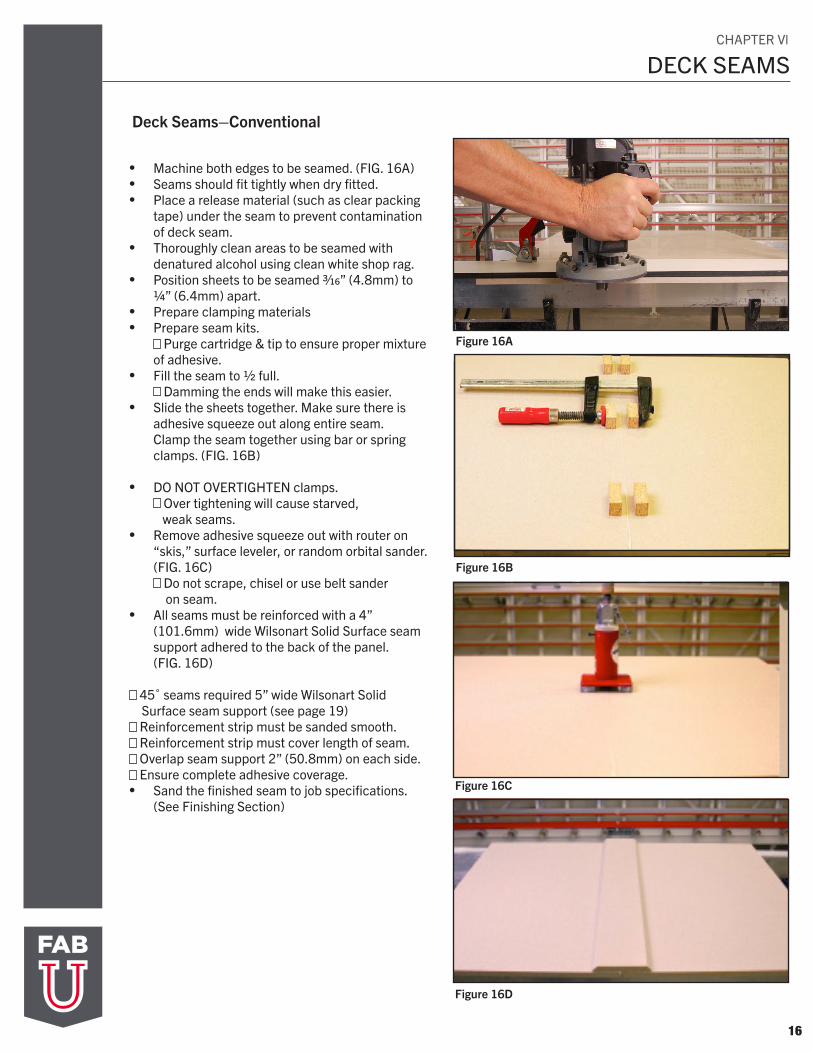
Deck Seams–Conventional
• Machine both edges to be seamed. (FIG. 16A)• Seams should fit tightly when dry fitted.• Place a release material (such as clear packing
tape) under the seam to prevent contaminationof deck seam.
• Thoroughly clean areas to be seamed withdenatured alcohol using clean white shop rag.
• Position sheets to be seamed 3/16” (4.8mm) to1/4” (6.4mm) apart.
• Prepare clamping materials• Prepare seam kits.
Purge cartridge & tip to ensure proper mixtureof adhesive.
• Fill the seam to 1/2 full. Damming the ends will make this easier.
• Slide the sheets together. Make sure there isadhesive squeeze out along entire seam. Clamp the seam together using bar or springclamps. (FIG. 16B)
• DO NOT OVERTIGHTEN clamps. Over tightening will cause starved,
weak seams.• Remove adhesive squeeze out with router on
“skis,” surface leveler, or random orbital sander. (FIG. 16C)
Do not scrape, chisel or use belt sander on seam.
• All seams must be reinforced with a 4” (101.6mm) wide Wilsonart Solid Surface seam support adhered to the back of the panel.(FIG. 16D)
45˚ seams required 5” wide Wilsonart Solid Surface seam support (see page 19)
Reinforcement strip must be sanded smooth. Reinforcement strip must cover length of seam. Overlap seam support 2” (50.8mm) on each side. Ensure complete adhesive coverage.
• Sand the finished seam to job specifications. (See Finishing Section)
Figure 16D
Figure 16C
Figure 16B
Figure 16A
CHAPTER Vl
17
DECK SEAMS
Figure 17C
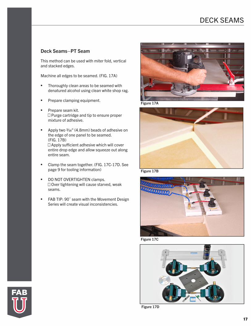
Deck Seams–PT Seam
Figure 17A
Figure 17B
This method can be used with miter fold, vertical and stacked edges.
Machine all edges to be seamed. (FIG. 17A)
• Thoroughly clean areas to be seamed with denatured alcohol using clean white shop rag.
• Prepare clamping equipment.
• Prepare seam kit. Purge cartridge and tip to ensure proper
mixture of adhesive.
• Apply two 3/16” (4.8mm) beads of adhesive on the edge of one panel to be seamed. (FIG. 17B)
Apply sufficient adhesive which will cover entire drop edge and allow squeeze out along entire seam.
• Clamp the seam together. (FIG. 17C-17D. See page 9 for tooling information)
• DO NOT OVERTIGHTEN clamps. Over tightening will cause starved, weak
seams.
• FAB TIP: 90˚ seam with the Movement Design Series will create visual inconsistencies.
Figure 17D
18
DECK SEAMS
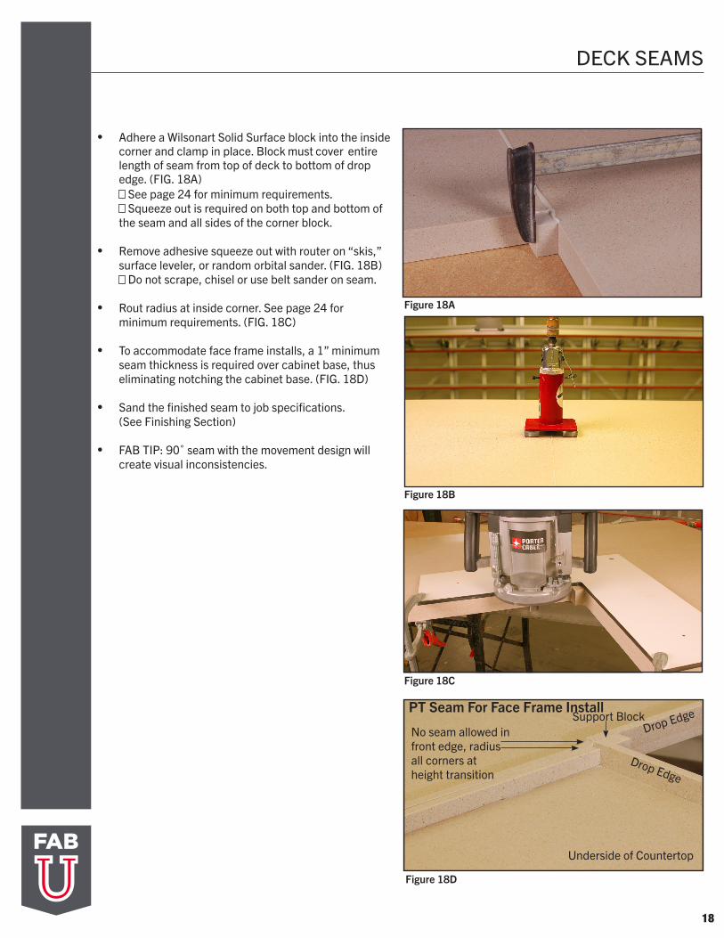
• Adhere a Wilsonart Solid Surface block into the inside corner and clamp in place. Block must cover entire length of seam from top of deck to bottom of drop edge. (FIG. 18A)
See page 24 for minimum requirements. Squeeze out is required on both top and bottom of
the seam and all sides of the corner block.
• Remove adhesive squeeze out with router on “skis,” surface leveler, or random orbital sander. (FIG. 18B)
Do not scrape, chisel or use belt sander on seam.
• Rout radius at inside corner. See page 24 forminimum requirements. (FIG. 18C)
• To accommodate face frame installs, a 1” minimumseam thickness is required over cabinet base, thuseliminating notching the cabinet base. (FIG. 18D)
• Sand the finished seam to job specifications. (See Finishing Section)
• FAB TIP: 90˚ seam with the movement design willcreate visual inconsistencies.
Figure 18A
Figure 18B
Figure 18C
Figure 18D
No seam allowed in front edge, radius all corners at height transition
Underside of Countertop
Drop Edge
Drop Edge
Support BlockPT Seam For Face Frame Install
DECK SEAMS
19
Deck Seams–45° Seam
This method is recommended to be used for movement or directional designs. Conventional 45° seams are the preferred method for seaming, allowing the pattern movement to continue throughout the application and flow in similar direction through the angle or corner.
Oversize the width of both sections being seamed by a minimum of 1” (25.4mm) on each section. • To be based on finished countertop dimension (i.e. 26”
(660.4mm) for a finished standard 25” (635.0mm)countertop depth).
• This will allow for adequate material once corner and profileare machined and allow for edge detail seams distance fromthe inside corner.
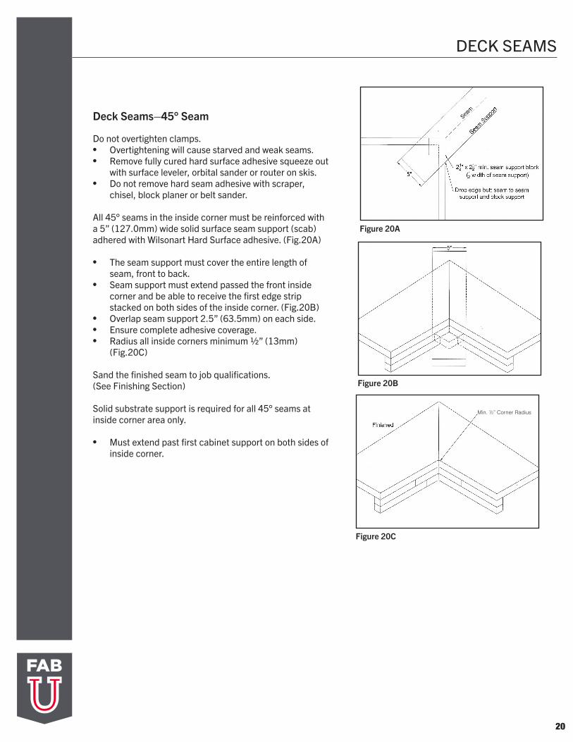
Machine both edges to be seamed.
Alignment biscuits/wafers (synthetic only) or slot bits are recommended for alignment, leveling and to eliminate movement of 45° seaming process. Use of Wilsonart Hard Surface adhesive is recommended.
Seams should fit tightly when dry fitted.
Place a release material (such as packing tape) under the seam to prevent contamination of deck seam.
Thoroughly clean areas to be seamed with denatured alcohol using clean white shop rag.
Position sheets to be seamed 3/16” (4.8mm) to ¼” (6.4mm) apart.
Prepare clamping materials.
Prepare Wilsonart Hard Surface adhesive seam kits.• Purge cartridge and tip to ensure proper mixture of adhesive.• Fill the seam to ½ full. • Damming the ends will make this process easier.• Slide the sheets together. Make sure there is adhesive
squeeze out along the entire length of seam.
Clamp the seam together using selected clamping process; wood blocks or suction cups with spring clamps, bar clamps and/or other seaming system.
DECK SEAMS
20
Deck Seams–45° Seam
Do not overtighten clamps.• Overtightening will cause starved and weak seams.• Remove fully cured hard surface adhesive squeeze out
with surface leveler, orbital sander or router on skis. • Do not remove hard seam adhesive with scraper,
chisel, block planer or belt sander.
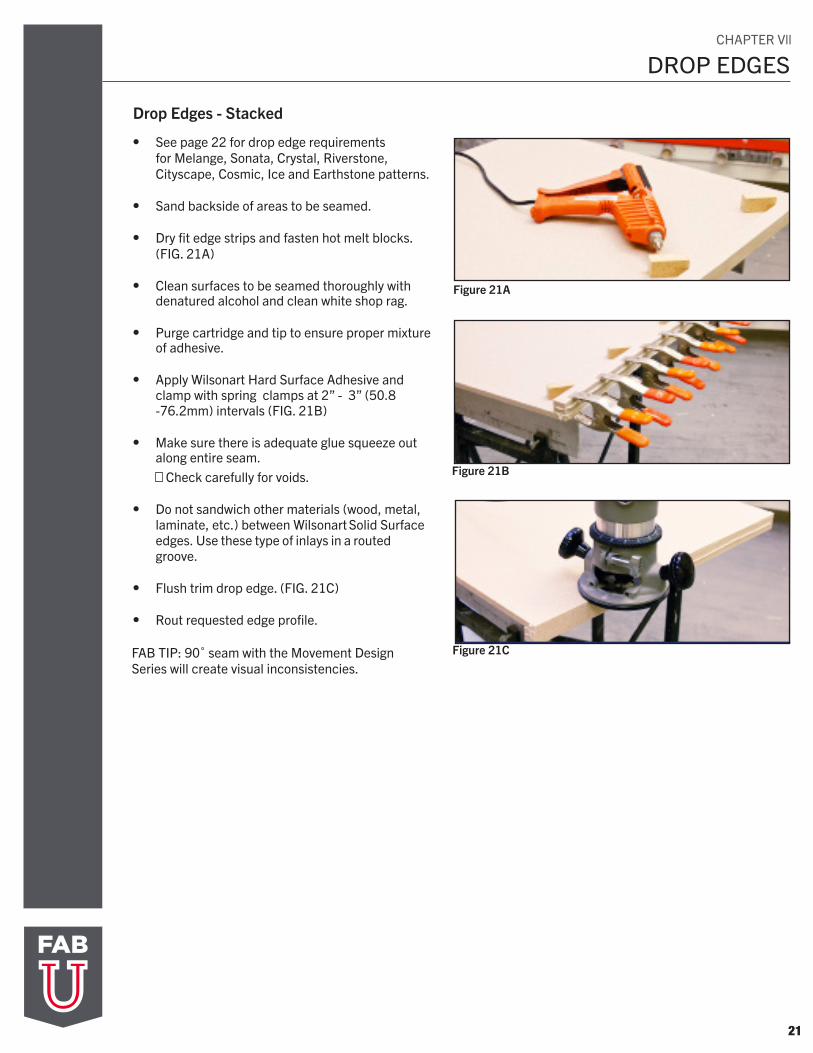
All 45° seams in the inside corner must be reinforced with a 5” (127.0mm) wide solid surface seam support (scab) adhered with Wilsonart Hard Surface adhesive. (Fig.20A)
• The seam support must cover the entire length ofseam, front to back.
• Seam support must extend passed the front insidecorner and be able to receive the first edge stripstacked on both sides of the inside corner. (Fig.20B)
• Overlap seam support 2.5” (63.5mm) on each side.• Ensure complete adhesive coverage.• Radius all inside corners minimum 1/2” (13mm)
(Fig.20C)
Sand the finished seam to job qualifications. (See Finishing Section)
Solid substrate support is required for all 45° seams at inside corner area only.
• Must extend past first cabinet support on both sides ofinside corner.
Figure 20C
Figure 20A
Figure 20B
Min. 1/2” Corner Radius
21
DROP EDGES
Drop Edges - Stacked
• See page 22 for drop edge requirementsfor Melange, Sonata, Crystal, Riverstone, Cityscape, Cosmic, Ice and Earthstone patterns.
• Sand backside of areas to be seamed.
• Dry fit edge strips and fasten hot melt blocks. (FIG. 21A)
• Clean surfaces to be seamed thoroughly with denatured alcohol and clean white shop rag.
• Purge cartridge and tip to ensure proper mixture of adhesive.
• Apply Wilsonart Hard Surface Adhesive and clamp with spring clamps at 2” - 3” (50.8 -76.2mm) intervals (FIG. 21B)
• Make sure there is adequate glue squeeze out along entire seam.
Check carefully for voids.
• Do not sandwich other materials (wood, metal, laminate, etc.) between Wilsonart Solid Surface edges. Use these type of inlays in a routed groove.
• Flush trim drop edge. (FIG. 21C)
• Rout requested edge profile.
FAB TIP: 90˚ seam with the Movement Design Series will create visual inconsistencies.
Figure 21A
Figure 21B
Figure 21C
CHAPTER Vll
22
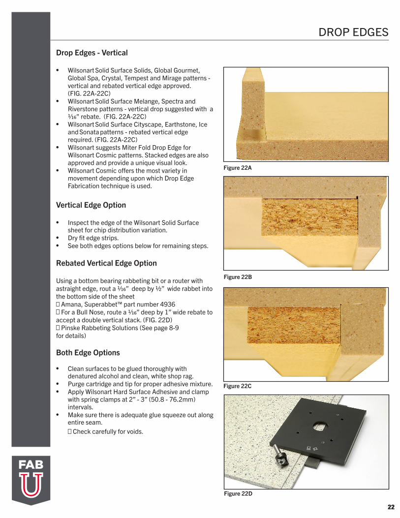
DROP EDGES
Figure 22C
Figure 22A
Figure 22B
Drop Edges - Vertical
• Wilsonart Solid Surface Solids, Global Gourmet, Global Spa, Crystal, Tempest and Mirage patterns -vertical and rebated vertical edge approved. (FIG. 22A-22C)
• Wilsonart Solid Surface Melange, Spectra and Riverstone patterns - vertical drop suggested with a 1/16" rebate. (FIG. 22A-22C)
• Wilsonart Solid Surface Cityscape, Earthstone, Ice and Sonata patterns - rebated vertical edge required. (FIG. 22A-22C)
• Wilsonart suggests Miter Fold Drop Edge for Wilsonart Cosmic patterns. Stacked edges are also approved and provide a unique visual look.
• Wilsonart Cosmic offers the most variety in movement depending upon which Drop Edge Fabrication technique is used.
Vertical Edge Option
• Inspect the edge of the Wilsonart Solid Surface sheet for chip distribution variation.
• Dry fit edge strips.• See both edges options below for remaining steps.
Rebated Vertical Edge Option
Using a bottom bearing rabbeting bit or a router with astraight edge, rout a 1/16” deep by 1/2” wide rabbet into the bottom side of the sheet
Amana, Superabbet™ part number 4936 For a Bull Nose, route a 1/16” deep by 1” wide rebate to
accept a double vertical stack. (FIG. 22D) Pinske Rabbeting Solutions (See page 8-9
for details)
Both Edge Options
• Clean surfaces to be glued thoroughly with denatured alcohol and clean, white shop rag.
• Purge cartridge and tip for proper adhesive mixture.• Apply Wilsonart Hard Surface Adhesive and clamp
with spring clamps at 2” - 3” (50.8 - 76.2mm) intervals.
• Make sure there is adequate glue squeeze out along entire seam.
Check carefully for voids.
Figure 22D
23
DROP EDGES
Drop Edges - Miter Fold Drop Edges
• Wilsonart suggests Miter Fold Drop Edge for Wilsonart Cosmic pattern.
• Place Wilsonart Solid Surface face down on a solid, flat work surface.
• Remove corner block and trim hinge tape.
• Clean miter area thoroughly with denatured alcohol and clean with white shop rag.
• Apply a 1/16” bead of Wilsonart Hard Surface Adhesive in the entire length of the miter fold seam. Also apply a 1/16” bead at one corner to be folded. (FIG. 23A)
• Fold up drop edge and clamp into place. Cam action clamps are suggested. (FIG. 23B) Clamps should be within 2" (50.8mm) from each corner and located every 12" (304.8mm). Place clamps 1/4" (6.4mm) above the face of the panel to ensure proper pressure.
• FAB TIP: Once drop edge is folded into place, do not allow the edge to separate from the deck.
• Fold up the end caps and secure in place withspring clamps or 3 way clamps. Clamps shouldbe placed every 2” (50.8mm). (FIG. 23C)
Place 3 way clamps 1/4” (6.4mm) above theface of the panel.
• Adhesive squeeze out is required along entirelength of seam and at all corners.
• Allow seam adhesive to cure completely beforemachining.
Figure 23A
Figure 23C
Figure 23B
Hinge Tape
Wilsonart® Hard Surface Adhesive
24
DROP EDGES
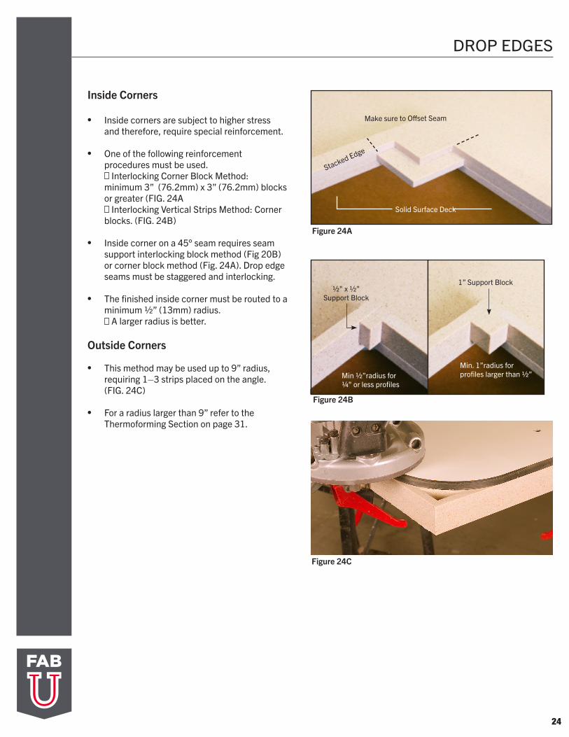
Inside Corners
• Inside corners are subject to higher stress and therefore, require special reinforcement.
• One of the following reinforcement procedures must be used.
Interlocking Corner Block Method: minimum 3” (76.2mm) x 3” (76.2mm) blocks or greater (FIG. 24A
Interlocking Vertical Strips Method: Corner blocks. (FIG. 24B)
• Inside corner on a 45° seam requires seam support interlocking block method (Fig 20B) or corner block method (Fig. 24A). Drop edge seams must be staggered and interlocking.
• The finished inside corner must be routed to a minimum 1/2” (13mm) radius.
A larger radius is better.
Outside Corners
• This method may be used up to 9” radius, requiring 1–3 strips placed on the angle. (FIG. 24C)
• For a radius larger than 9” refer to the Thermoforming Section on page 31.
Figure 24A
Figure 24C
Stacked Edge
Solid Surface Deck
Min 1/2”radius for 1/4" or less profiles
Min. 1”radius for profiles larger than 1/2”
1” Support Block1/2" x 1/2"
Support Block
Figure 24B
Make sure to Offset Seam
25
SINKS
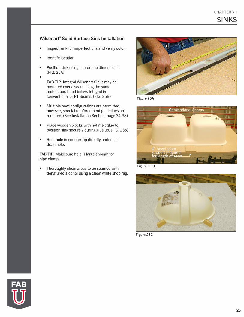
Wilsonart® Solid Surface Sink Installation
• Inspect sink for imperfections and verify color.
• Identify location
•
•
Position sink using center-line dimensions. (FIG. 25A)
FAB TIP: Integral Wilsonart Sinks may be mounted over a seam using the same techniques listed below. Integral in conventional or PT Seams. (FIG. 25B)
• Multiple bowl configurations are permitted;however, special reinforcement guidelines arerequired. (See Installation Section, page 34-38)
• Place wooden blocks with hot melt glue toposition sink securely during glue up. (FIG. 235)
• Rout hole in countertop directly under sinkdrain hole.
FAB TIP: Make sure hole is large enough for pipe clamp.
• Thoroughly clean areas to be seamed withdenatured alcohol using a clean white shop rag.
Figure 25A
Figure 25B
Figure 25C
Conventional Seams
4" bevel seam support required for length of seam
CHAPTER Vlll
26
SINKS
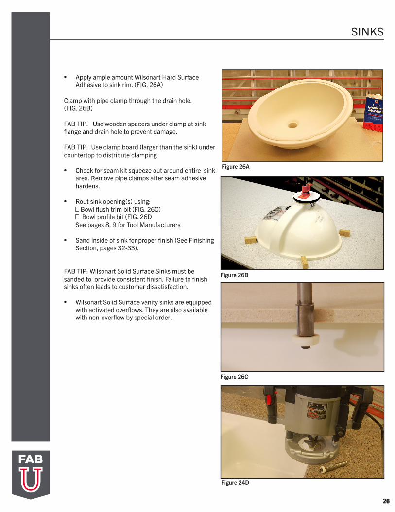
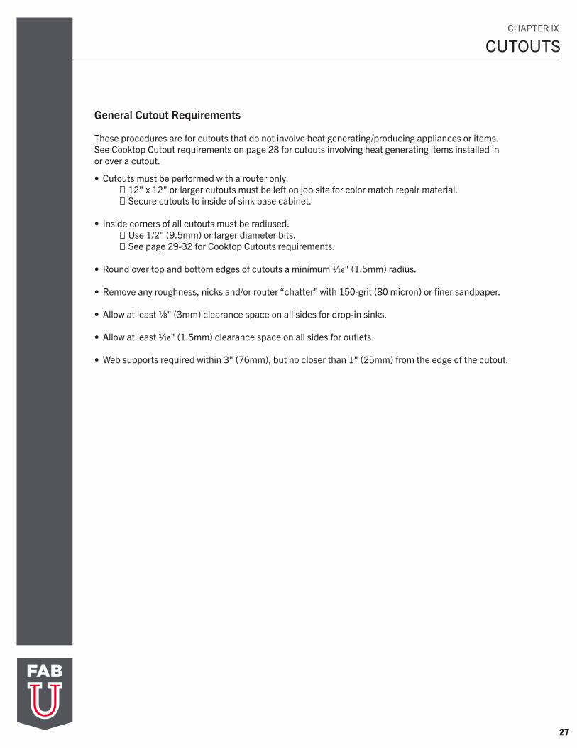
• Apply ample amount Wilsonart Hard Surface Adhesive to sink rim. (FIG. 26A)
Clamp with pipe clamp through the drain hole. (FIG. 26B)
FAB TIP: Use wooden spacers under clamp at sink flange and drain hole to prevent damage.
FAB TIP: Use clamp board (larger than the sink) under countertop to distribute clamping
• Check for seam kit squeeze out around entire sinkarea. Remove pipe clamps after seam adhesivehardens.
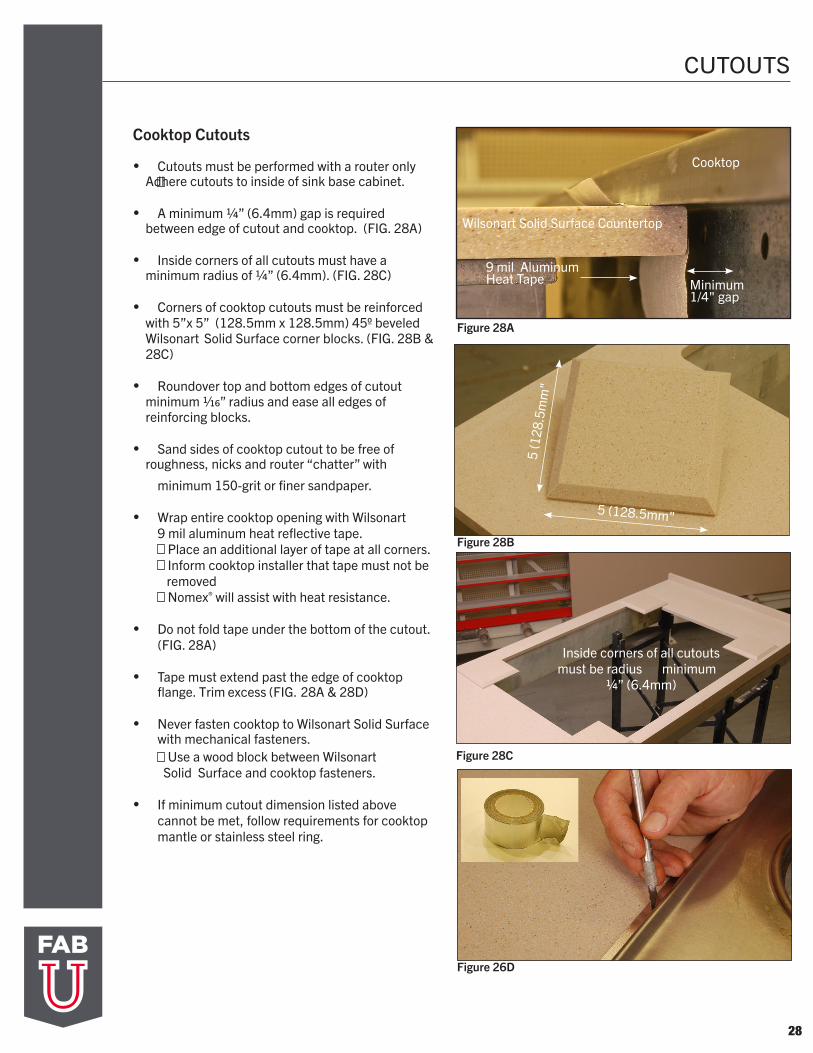
• Rout sink opening(s) using:Bowl flush trim bit (FIG. 26C)Bowl profile bit (FIG. 26D
See pages 8, 9 for Tool Manufacturers
• Sand inside of sink for proper finish (See FinishingSection, pages 32-33).
FAB TIP: Wilsonart Solid Surface Sinks must be sanded to provide consistent finish. Failure to finish sinks often leads to customer dissatisfaction.
• Wilsonart Solid Surface vanity sinks are equipped with activated overflows. They are also available with non-overflow by special order.
Figure 26B
Figure 26C
Figure 24D
Figure 26A
CUTOUTS
27
General Cutout Requirements These procedures are for cutouts that do not involve heat generating/producing appliances or items. See Cooktop Cutout requirements on page 28 for cutouts involving heat generating items installed in or over a cutout.
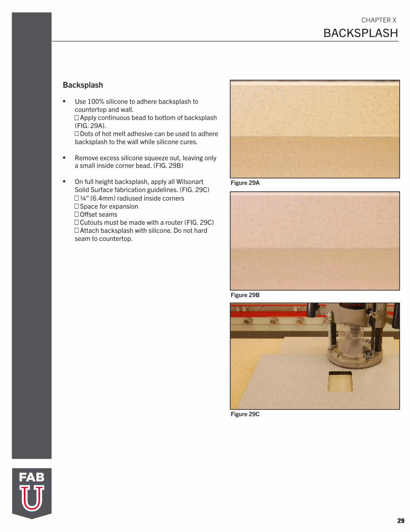
• Cutouts must be performed with a router only. 12" x 12" or larger cutouts must be left on job site for color match repair material. Secure cutouts to inside of sink base cabinet. • Inside corners of all cutouts must be radiused. Use 1/2" (9.5mm) or larger diameter bits. See page 29-32 for Cooktop Cutouts requirements.
• Round over top and bottom edges of cutouts a minimum 1/16" (1.5mm) radius.
• Remove any roughness, nicks and/or router “chatter” with 150-grit (80 micron) or finer sandpaper.
• Allow at least 1/8" (3mm) clearance space on all sides for drop-in sinks.
• Allow at least 1/16" (1.5mm) clearance space on all sides for outlets.
• Web supports required within 3" (76mm), but no closer than 1" (25mm) from the edge of the cutout.
CHAPTER lX
CUTOUTS
28
Figure 28A
Figure 28B
Figure 28C
Figure 26D
Cooktop Cutouts
• Cutouts must be performed with a router only Adhere cutouts to inside of sink base cabinet.
• A minimum 1/4” (6.4mm) gap is required between edge of cutout and cooktop. (FIG. 28A)
• Inside corners of all cutouts must have a minimum radius of 1/4” (6.4mm). (FIG. 28C)
• Corners of cooktop cutouts must be reinforced with 5”x 5” (128.5mm x 128.5mm) 45º beveled Wilsonart Solid Surface corner blocks. (FIG. 28B & 28C)
• Roundover top and bottom edges of cutout minimum 1/16” radius and ease all edges of reinforcing blocks.
• Sand sides of cooktop cutout to be free of roughness, nicks and router “chatter” with
minimum 150-grit or finer sandpaper.
• Wrap entire cooktop opening with Wilsonart
9 mil aluminum heat reflective tape. Place an additional layer of tape at all corners. Inform cooktop installer that tape must not be
removed Nomex® will assist with heat resistance.
• Do not fold tape under the bottom of the cutout. (FIG. 28A)
• Tape must extend past the edge of cooktop flange. Trim excess (FIG. 28A & 28D)
• Never fasten cooktop to Wilsonart Solid Surface with mechanical fasteners.
Use a wood block between Wilsonart Solid Surface and cooktop fasteners.
• If minimum cutout dimension listed abovecannot be met, follow requirements for cooktopmantle or stainless steel ring.
Cooktop
9 mil Aluminum Heat Tape Minimum
1/4" gap
Wilsonart Solid Surface Countertop
5 (128.5mm"5
(128
.5m
m"
Inside corners of all cutouts must be radius minimum
1/4” (6.4mm)
29
BACKSPLASH
Backsplash
• Use 100% silicone to adhere backsplash tocountertop and wall.
Apply continuous bead to bottom of backsplash (FIG. 29A).
Dots of hot melt adhesive can be used to adhere backsplash to the wall while silicone cures.
• Remove excess silicone squeeze out, leaving only a small inside corner bead. (FIG. 29B)
• On full height backsplash, apply all Wilsonart
Solid Surface fabrication guidelines. (FIG. 29C) 1/4” (6.4mm) radiused inside corners Space for expansion Offset seams Cutouts must be made with a router (FIG. 29C) Attach backsplash with silicone. Do not hard
seam to countertop.
Figure 29A
Figure 29B
Figure 29C
CHAPTER X
30
BACKSPLASH
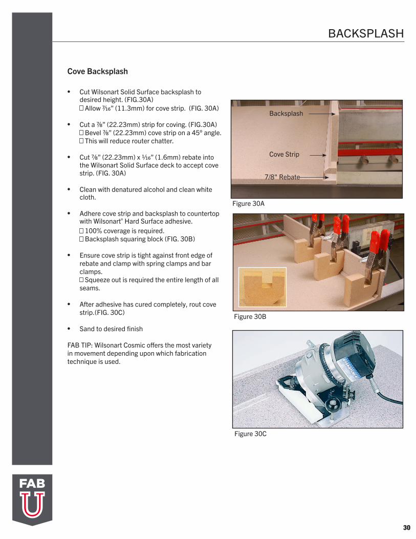
Cove Backsplash
Figure 30A
Figure 30C
Backsplash
Cove Strip
7/8" Rebate
• Cut Wilsonart Solid Surface backsplash to desired height. (FIG.30A)
Allow 7/16” (11.3mm) for cove strip. (FIG. 30A)
• Cut a 7/8” (22.23mm) strip for coving. (FIG.30A)Bevel 7/8” (22.23mm) cove strip on a 45° angle. This will reduce router chatter.
• Cut 7/8” (22.23mm) x 1/16” (1.6mm) rebate into the Wilsonart Solid Surface deck to accept cove strip. (FIG. 30A)
• Clean with denatured alcohol and clean white cloth.
• Adhere cove strip and backsplash to countertop with Wilsonart® Hard Surface adhesive.
100% coverage is required. Backsplash squaring block (FIG. 30B)
• Ensure cove strip is tight against front edge ofrebate and clamp with spring clamps and barclamps.
Squeeze out is required the entire length of all seams.
• After adhesive has cured completely, rout covestrip.(FIG. 30C)
• Sand to desired finish
FAB TIP: Wilsonart Cosmic offers the most variety in movement depending upon which fabrication technique is used.
Figure 30B
31
THERMOFORMING
Figure 31A
Figure 31B
Figure 31C
Thermoforming
• To thermoform Wilsonart Solid Surface material, an oven that will heat the material is needed. (FIG. 31A)
• The sheet temperatures should be between 280° to 325°F (137.8° to 162.7° C) throughout the thickness during bending
FAB TIP: Cold spots in the sheet will lead to cracks and whitening. Hot spots may cause blistering, discoloration, whitening and cracks.
• Thermoforming is not recommended orapproved by Wilsonart for the Cityscape, Cosmicand Ice Collections. Please contact WilsonartTechnical Service Group at 800-433-3222 forfurther information.
Wilsonart Solid Surface material has a minimum bending radius of 3” (76.2mm).
FAB TIP: Bending sheets to a smaller radius can result in crazing, whitening, cracking, or reduction in impact resistance.
• For the best result, a set of male and female molds should be used to form the sheetinto the desired radius shape (this is highly recommended for thermoforming 1/2” (13mm) sheets. (FIG. 31B)
• Heat Guns, Torches and Cal Rods willcause failure with Wilsonart Solid Surface countertops.
FAB TIP: Spot heating or localized heating will cause problems due to the temperature difference between the heated area and the unheated area. The stress build-up at the interface between the heated and unheated area will lead to cracking after the top is installed. (FIG. 31C)
Cool Down• Allow the thermoformed sheet to cool down in
the mold to less than 170° F (76.6° C) before removing from mold. Depending on the surrounding room temperature, cool down will take approximately 20 to 40 minutes.
Seaming• All seaming must be done after thermoforming.
CHAPTER Xl
32
FINISHING
Figure 32A
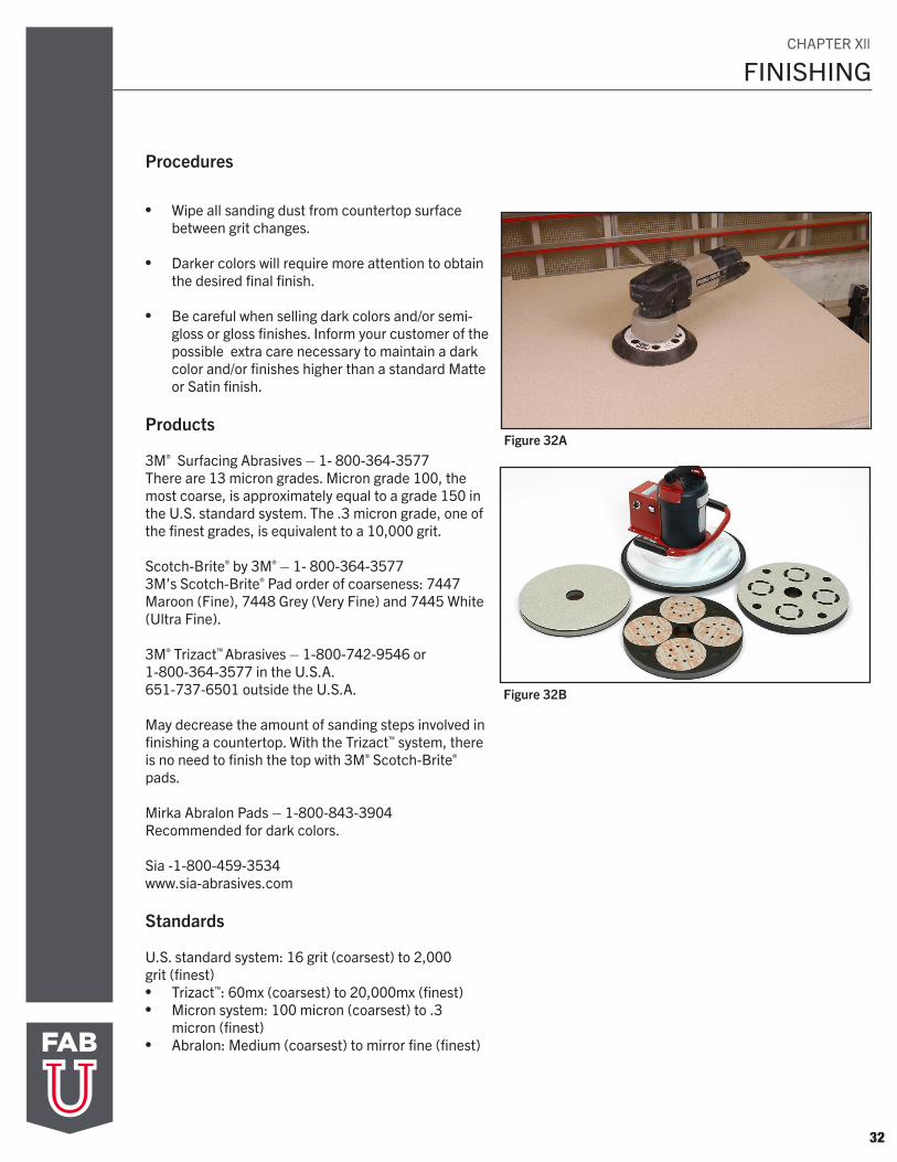
Procedures
• Wipe all sanding dust from countertop surface between grit changes.
• Darker colors will require more attention to obtain the desired final finish.
• Be careful when selling dark colors and/or semi-gloss or gloss finishes. Inform your customer of the possible extra care necessary to maintain a dark color and/or finishes higher than a standard Matte or Satin finish.
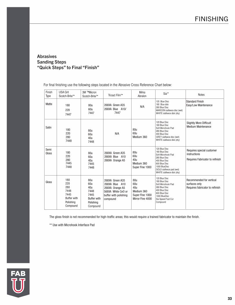
Products
3M® Surfacing Abrasives – 1- 800-364-3577There are 13 micron grades. Micron grade 100, the most coarse, is approximately equal to a grade 150 in the U.S. standard system. The .3 micron grade, one of the finest grades, is equivalent to a 10,000 grit. Scotch-Brite® by 3M® – 1- 800-364-3577 3M’s Scotch-Brite® Pad order of coarseness: 7447 Maroon (Fine), 7448 Grey (Very Fine) and 7445 White (Ultra Fine).
3M® Trizact™ Abrasives – 1-800-742-9546 or 1-800-364-3577 in the U.S.A. 651-737-6501 outside the U.S.A.
May decrease the amount of sanding steps involved in finishing a countertop. With the Trizact™ system, there is no need to finish the top with 3M® Scotch-Brite® pads.
Mirka Abralon Pads – 1-800-843-3904Recommended for dark colors.
Sia -1-800-459-3534 www.sia-abrasives.com
Standards
U.S. standard system: 16 grit (coarsest) to 2,000 grit (finest) • Trizact™: 60mx (coarsest) to 20,000mx (finest)• Micron system: 100 micron (coarsest) to .3
micron (finest)• Abralon: Medium (coarsest) to mirror fine (finest)
Figure 32B
CHAPTER Xll
33
FINISHING
AbrasivesSanding Steps “Quick Steps” to Final “Finish”
FinishType Notes
Standard Finish Easy/Low Maintenance
Slightly More DifficultMedium Maintenance
Requires special customer instructions
Requires Fabricator to refinish
Recommended for vertical surfaces onlyRequires fabricator to refinish
N/A
80u60u Medium 360
80u60u 40uMedium 360Super Fine 1000
80u60u 40uMedium 360Super Fine 1000Mirror Fine 4000
Matte
Satin
SemiGloss
3M MicronScotch-Brite™
™
18022028074487445Buffer withPolishing Compound
180
2207447
1802202807448
180220280
74487445
268XA Green A35268XA Blue A10/ 7447
N/A
268XA Green A35268XA Blue A10268XA Orange A5
268XA Green A35268XA Blue A10268XA Orange A5568XA White CeO orbuffer with polishing compound
80u60u7447
80u60u 40u7448
80u60u40u
74487445
80u60u40u74487445Buffer withPolishing Compound
Gloss
USA GritScotch-Brite™ Trizact Film™
MirkaAbralon
For final finishing use the following steps located in the Abrasive Cross Reference Chart below:
The gloss finish is not recommended for high-traffic areas; this would require a trained fabricator to maintain the finish.
** Use with Microhook Interface Pad
Sia**
120 Blue Disc180 Blue disk280 Blue DiscMAROON siafleece disc (wet)WHITE siafleece disk (dry)
120 Blue Disc180 Blue DiscSoft Microhook Pad 280 Blue Disc400 Blue DiscGREY siafleece disc (wet)WHITE siafleece disk (dry)
120 Blue Disc180 Blue DiscSoft Microhook Pad280 Blue Disc400 Blue Disc600 Blue Disc1000 BlueDiscGOLD siafleece pad (wet)WHITE siafleece disk (dry)
120 Blue Disc180 Blue DiscSoft Microhook Pad280 Blue Disc400 Blue Disc600 Blue Disc1000 BlueDiscSia Speed Fast Cut Compound
34
INSTALLATION
Figure 34A
Figure 34B
Jobsite Preparation
INSTALLATION
06/01/2002Gibraltar® Solid SurfaceEarthstone® Solid Surface
ShimCabinet
Web Support
Figure 29A
Figure 29B
Jobsite Preparation
Jobsite Preparation 29
• Install web supports as required.Place around perimeter of countertop and ateach cabinet support.
• Webbing must be straight, flat and level afterinstallation. If shims are used, they must be installedbetween the cabinet and the web frames, notdirectly under the countertop. (FIG. 29A)
• Do not install Wilsonart Solid Surface over a solidsubstrate, except at overhangs. (See page 30)
• Certain unsupported areas are in need of strongerframe material. These include inside cornercabinets, especially lazy Susans, dishwasheropenings, sink base fronts, desks and anywhere elsethat the cabinet is weaker than others. (FIG. 29B)
• Place web supports at both sides of all cutouts. Placesupports no closer than 1" (25.4mm) and no furtherthan 3" ( 76.2mm) from sides of cutout.
See page 28 for additional web supportrequirements.
• Multiple bowl installations require specialreinforcement to provide adequate support.
Place web support along both sides of the bowlinstallation.Place sink setters, solid wood, MDF orplywood supports between each bowl.Supports must rest on cabinet base or beattached to cabinet base to alleviate flexing.
Web Support
High Strength Support
Lazy SusanCorner Cabinet
Reinforce unsupported area
• Install web supports as required. 1/2” or 3/4” MDF or particle board recommended. Place around perimeter of countertop and at
each cabinet support.
• Webbing must be straight, flat and level afterinstallation. If shims are used, they must be installed between the cabinet and the web frames, not directly under the countertop. (FIG. 34A)
• Do not install Wilsonart Solid Surface over a solidsubstrate, except at overhangs and 45° seams (See page 20 &35)
Solid substrate support is required for all 45° seams at inside corner area only, and must extend past the first cabinet support on both sides of inside corner.
• Supports required every 24”.
• Certain unsupported areas are in need of strongerframe material. These include inside corner cabinets, especially lazy susan, dishwasher openings, sink base fronts, desks and anywhere else that the cabinet is weaker than others. (FIG. 34B)
• Place web supports at both sides of all cutouts. Place supports no closer than 1” (25.4mm) and no further than 3” ( 76.2mm) from sides of cutout.
See page 36 for additional web support requirements.
• Multiple bowl installations require specialreinforcement to provide adequate support.
Place web support along both sides of the bowl installation.
Place sink setters, solid wood, MDF or plywoodsupports between each bowl.
Supports must rest on cabinet base or be attached to cabinet base to alleviate flexing.
• Free standing stoves must be set min. 1/16” higherthan surface of countertop.
CHAPTER Xlll
35
INSTALLATION
Figure 35A
Overhangs
Figure 35C
• Additional support is required when the countertop overhangs the cabinet. (FIG. 35A) Refer to the following chart to determine support required:
Figure 35B
• When brackets (corbels) are used, place them no more than 24” (609.6mm) apart. In addition, place brackets 12” (304.8mm) from open ends and against wall ends. (FIG. 35B & 35C)
INSTALLATION
06/01/2002Gibraltar® Solid SurfaceEarthstone® Solid Surface
Figure 30A
Overhangs 30
Overhangs
Figure 30C
• Additional support is required when the countertopoverhangs the cabinet. (FIG. 30A) Refer to thefollowing chart to determine support required:
Figure 30B• When brackets (corbels) are used, place them no
more than 24" (609.6mm) apart. In addition, placebrackets 12" (304.8mm) from open ends and againstwall ends. (FIG. 30B & 30C)
(FIG. 27A)
(FIG. 27B)
Overhang
0 - 6" (0-152.4mm)
12 - 18"(304.8mm-457.2mm)
18 - 24"(457.2mm-609.6mm)
6 - 12"(152.4mm-304.8mm)
Support Required
None
Brackets (corbels)(Under web frame support)
3/4" plywood underlaymentor
Brackets (corbels)(Under web frame support)
3/4" plywood underlaymentand
Brackets (corbels)
3/4" plywood underlayment
supporting legs
and
and
12" - 18"(304.8mm - 457.2mm)
Cabinet
Web Support
Countertop
12"Maximum (304.8mm)
24"Maximum (609.6mm)
Wall
Figure 39B
(Figure 39B)
36
INSTALLATION
Web Support Layout
Recommended web support material includes: Medium Density Fiberboard (MDF), plywood, hardboard etc.
Figure 36A (Option 1)
Figure 36B (Option 2)
INSTALLATION
06/01/2002Gibraltar® Solid SurfaceEarthstone® Solid Surface
Web Support Layout
Web Support Layout 31
Recommended web support material includes: Medium Density Fiberboard (MDF), plywood, hardboard etc.
Figure 31A (Option 1)
Figure 31B (Option 2)
Sink Base
OVE
RH
ANG
Corners require extra strength supports
Support at front, middleand back of all
cabinets
All ends require support
Support cutouts withadditional side
supports from 1" (25.4mm) to 3" (76.2mm)from sides of cutouts
Overhangs can be supported with plywood
(See "Overhangs")
Corner
Cooktop
DishWasher
Lazy Susan
Lazy Susan
Sink Base
DishWasher
Corner
Cooktop
OVE
RH
ANG
Corners require extra strength supports
Seam support
Seam support
Support at frontand back of all
cabinets
All ends require support
Support cutouts withadditional side
supports from 1" (25.4mm) to 3" (76.2mm)from sides of cutouts
Overhangs can be supported with plywood
(See "Overhangs")

37
INSTALLATION
Securing the Countertop
• Use only 100% pure silicone to secure countertop toweb frame.
No construction mastic
• Use dime sized dabs every 18” (457.2mm) to 24” (609.6mm).)
Secure all outside corners Do not run continuous beads Do not place silicone in the inside corners
• No mechanical fasteners should be used to fasten the countertop. Never screw, staple or nail into Wilsonart Solid Surface.
Fitting the Countertop
Provide minimum 1/8” (3.2mm) gap at all walls for every 12 feet of countertop. )
Scribe to wall as necessary.
38
INSTALLATION
Customer Satisfaction
Customer satisfaction is achieved by using a common sense approach. Treat your customer fairly. Word of mouth is the best and least expensive form of advertising. Quality assurance in fabrication and installation is of the utmost importance. The fabricator’s reputation hangs in the balance.
The following are mandatory:
• Repair material affixed to cabinet under sink. “Do Not Remove” should be written on
the material.
• Care and Maintenance information should beprovided to end user. Information can be foundat the Wilsonart website, www.wilsonart.com. (FIG. 38A)
Warranty Registration • On-line registration through the B2B website
(FIG. 38B & 38C)
Figure 38A
Figure 38B
Figure 38C