Embed Size (px)
Citation preview
Wifi Pan/Tilt IP Camera User Manual
Rev. 3.0
Software Version 3.00
May. 25th.2009
Table of Contents
1. PRODUCT VIEWS..............................................................................................................................................3
1.1. PRONT PANEL...................................................................................................................................................31.2. BACK PANEL ....................................................................................................................................................3 1.3. ACCESSORIES................................................................................................................................ 4
2. SETUP AND STARTUP .......................................................................................................................................5 2.1. CONNECTIONS.................................................................................................................................................5 2.2. SETUP AND STARTUP .......................................................................................................................................5
3. LOGIN AND SETTINGS ....................................................................................................................................8 3.1. LOGIN..............................................................................................................................................................8 3.1. OPERATION FOR VISITOR.................................................................................................................................9 3.3. OPERATION FOR ADMINISTRATOR.................................................................................................................. 11
3.3.1 ALIAS SETTINGS......................................................................................................................................12 3.3.2 USER SETTINGS.......................................................................................................................................12 3.3.3 BASIC NETWORK SETTINGS ....................................................................................................................12 3.3.4 WIRELESS LAN SETTINGS .......................................................................................................................13 3.3.5 ADSL SETTINGS......................................................................................................................................13 3.3.6 UPNP SETTINGS ......................................................................................................................................14 3.3.7 DDNS SERVICE SETTINGS.......................................................................................................................14 3.3.8 MAIL SERVICE SETTINGS.........................................................................................................................14 3.3.9 FTP SERVICE SETTINGS ...........................................................................................................................15 3.3.10 ALARM SERVICE SETTINGS ...................................................................................................................15
4. HOW TO VIEW ON THE INTERNET?.........................................................................................................17
4.1. ACQUIRE A DYNAMIC DOMAIN NAME...........................................................................................................17 4.2. SET THE IP ADDRESS OF THE CAMERA..........................................................................................................22 4.3. SET THE ROUTER...........................................................................................................................................22 4.4. SET THE IP CAMERA AT DDNS SETTINGS .....................................................................................................23
5. SPECIFICATIONS ............................................................................................................................................25
5.1. FEATURES......................................................................................................................................................25 5.2. SPECIFICATIONS ............................................................................................................................................25
6. APPENDIX .........................................................................................................................................................26
6.1. RESTORE FACTORY SETTINGS .......................................................................................................................26 6.2. TROUBLE SHOOTING .....................................................................................................................................26
1. Product Views
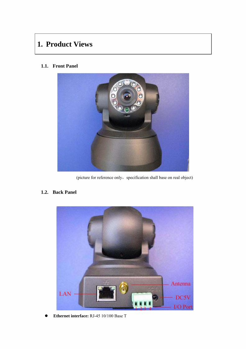
1.1. Front Panel
(picture for reference only,specification shall base on real object)
1.2. Back Panel
Ethernet interface: RJ-45 10/100 Base T
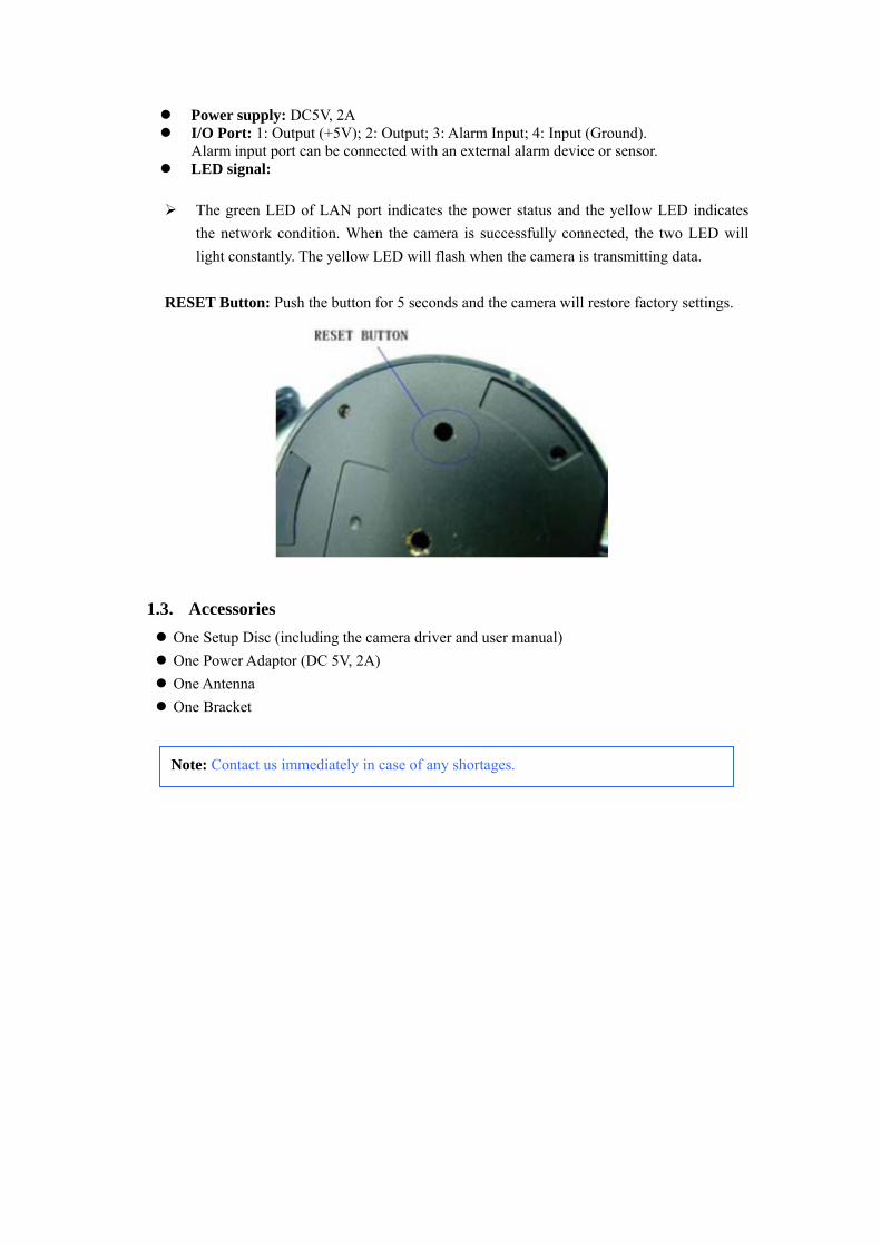
Power supply: DC5V, 2A I/O Port: 1: Output (+5V); 2: Output; 3: Alarm Input; 4: Input (Ground).
Alarm input port can be connected with an external alarm device or sensor. LED signal:
The green LED of LAN port indicates the power status and the yellow LED indicates the network condition. When the camera is successfully connected, the two LED will light constantly. The yellow LED will flash when the camera is transmitting data.
RESET Button: Push the button for 5 seconds and the camera will restore factory settings.
1.3. Accessories One Setup Disc (including the camera driver and user manual) One Power Adaptor (DC 5V, 2A) One Antenna One Bracket
Note: Contact us immediately in case of any shortages.
2. Setup and Startup
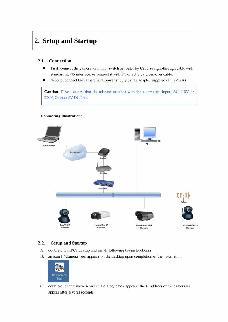
2.1. Connection First: connect the camera with hub, switch or router by Cat.5 straight-through cable with
standard RJ-45 interface, or connect it with PC directly by cross-over cable. Second, connect the camera with power supply by the adaptor supplied (DC5V, 2A).
Connecting Illustration:
2.2. Setup and Startup A. double-click IPCamSetup and install following the instructions; B. an icon IP Camera Tool appears on the desktop upon completion of the installation;
C. double-click the above icon and a dialogue box appears: the IP address of the camera will
appear after several seconds.
Caution: Please ensure that the adaptor matches with the electricity (Input: AC 110V or 220V, Output: 5V DC/2A).
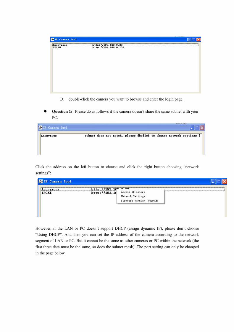
D. double-click the camera you want to browse and enter the login page.
Question 1:Please do as follows if the camera doesn’t share the same subnet with your PC.
Click the address on the left button to choose and click the right button choosing “network settings”:
However, if the LAN or PC doesn’t support DHCP (assign dynamic IP), please don’t choose “Using DHCP”. And then you can set the IP address of the camera according to the network segment of LAN or PC. But it cannot be the same as other cameras or PC within the network (the first three data must be the same, so does the subnet mask). The port setting can only be changed in the page below.
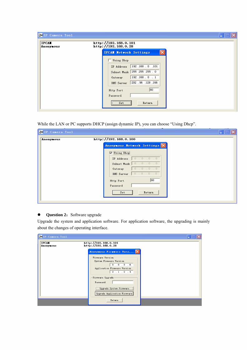
While the LAN or PC supports DHCP (assign dynamic IP), you can choose “Using Dhcp”.
Question 2:Software upgrade Upgrade the system and application software. For application software, the upgrading is mainly about the changes of operating interface.
3 Login and Settings
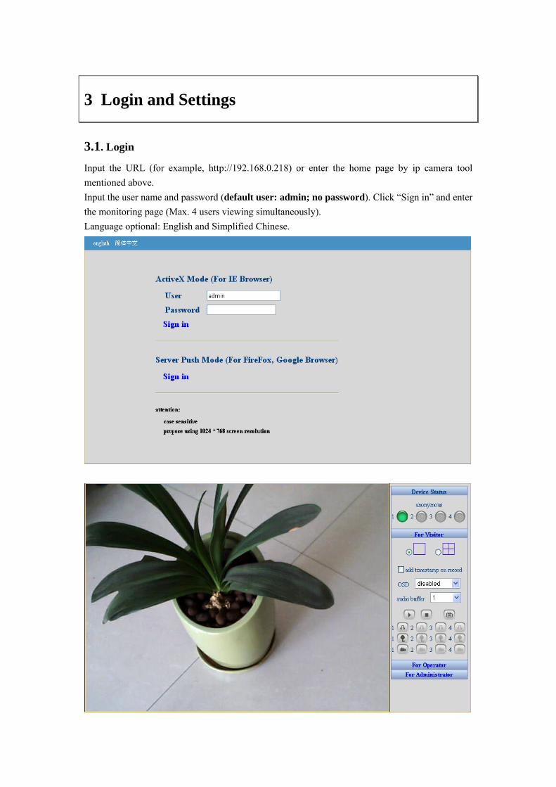
3.1. Login Input the URL (for example, http://192.168.0.218) or enter the home page by ip camera tool mentioned above. Input the user name and password (default user: admin; no password). Click “Sign in” and enter the monitoring page (Max. 4 users viewing simultaneously). Language optional: English and Simplified Chinese.
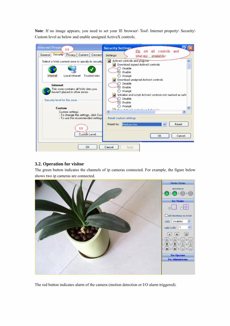
Note: If no image appears, you need to set your IE browser\ Tool\ Internet property\ Security\ Custom level as below and enable unsigned ActiveX controls.
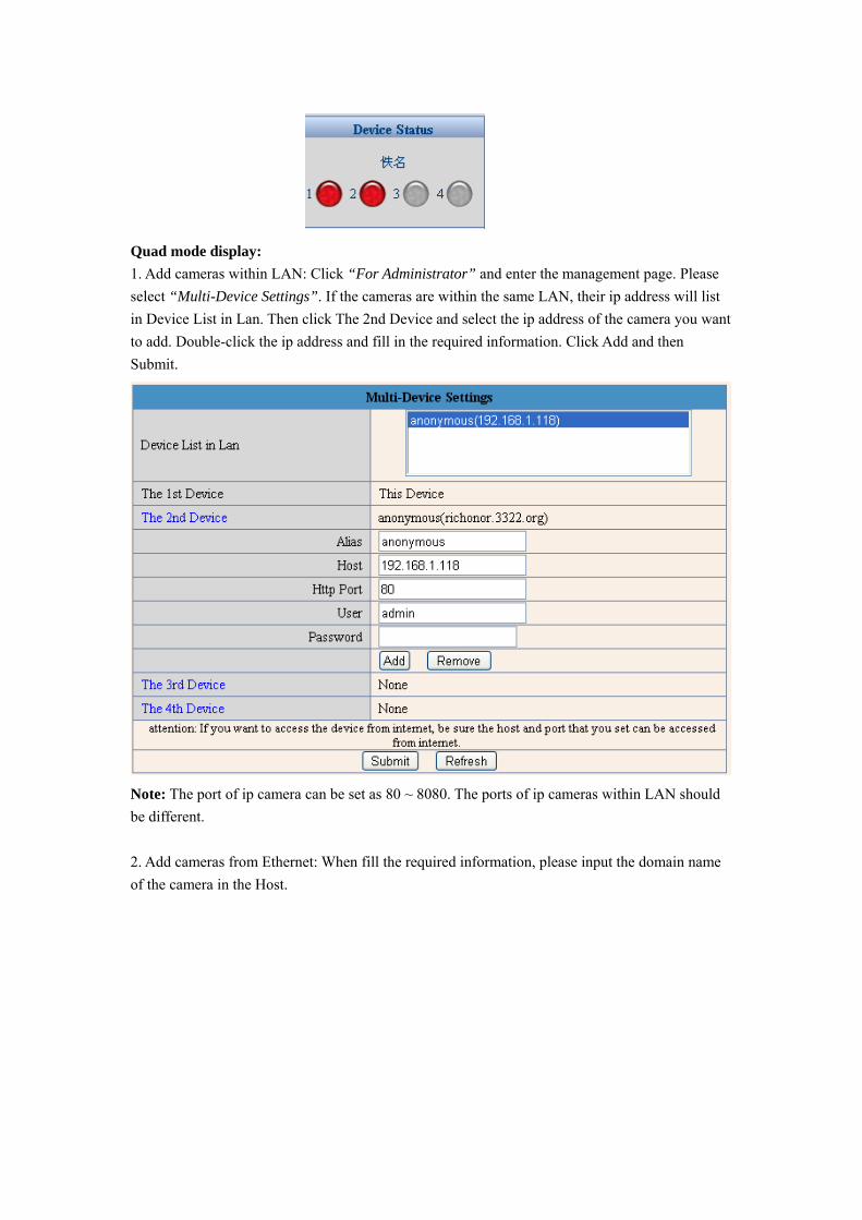
3.2. Operation for visitor The green button indicates the channels of ip cameras connected. For example, the figure below shows two ip cameras are connected.
The red button indicates alarm of the camera (motion detection or I/O alarm triggered).
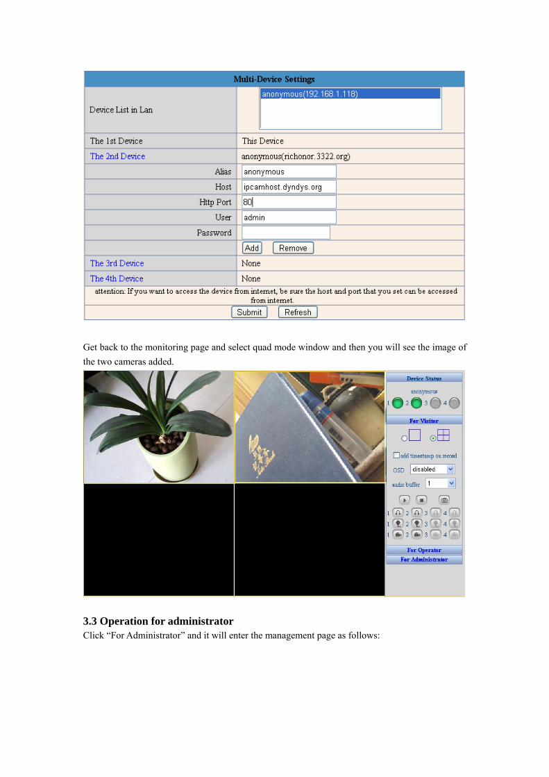
Quad mode display: 1. Add cameras within LAN: Click “For Administrator” and enter the management page. Please select “Multi-Device Settings”. If the cameras are within the same LAN, their ip address will list in Device List in Lan. Then click The 2nd Device and select the ip address of the camera you want to add. Double-click the ip address and fill in the required information. Click Add and then Submit.
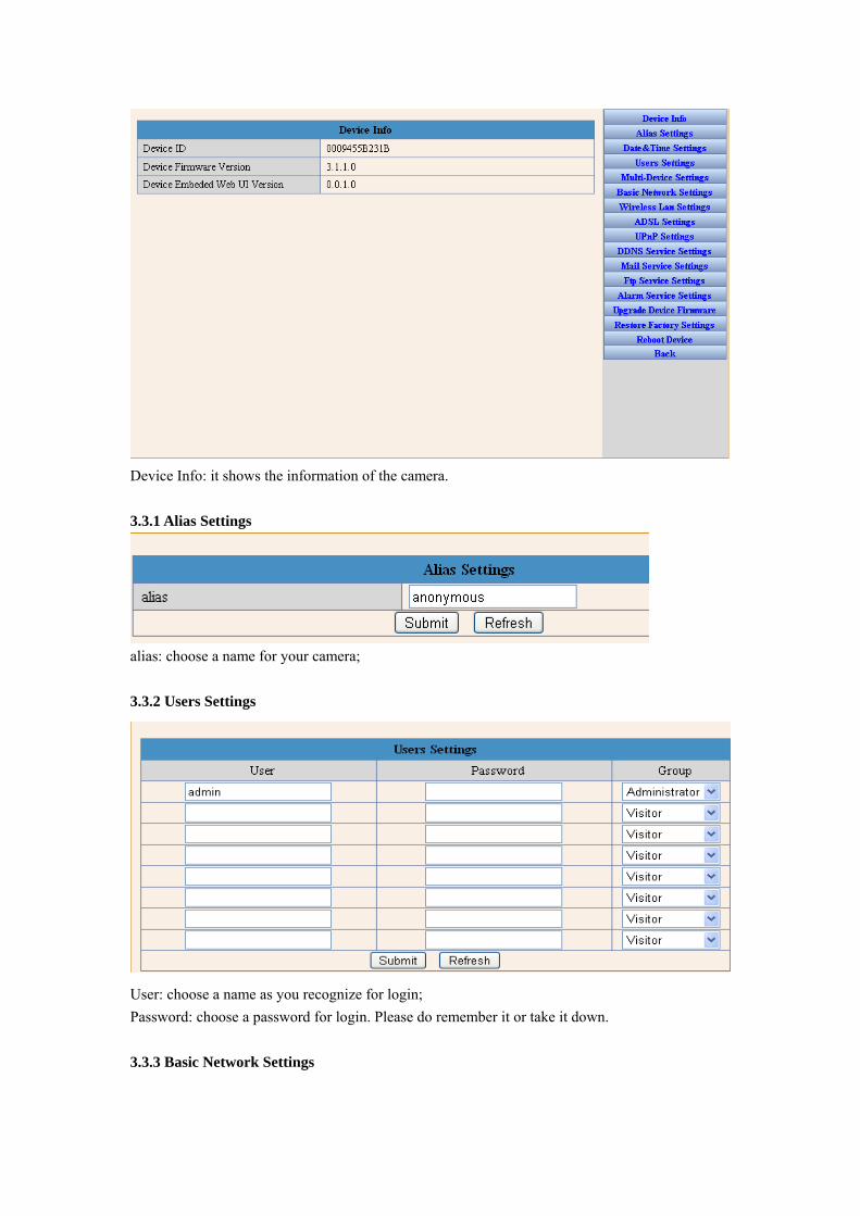
Note: The port of ip camera can be set as 80 ~ 8080. The ports of ip cameras within LAN should be different. 2. Add cameras from Ethernet: When fill the required information, please input the domain name of the camera in the Host.
Get back to the monitoring page and select quad mode window and then you will see the image of the two cameras added.
3.3 Operation for administrator Click “For Administrator” and it will enter the management page as follows:
Device Info: it shows the information of the camera. 3.3.1 Alias Settings
alias: choose a name for your camera; 3.3.2 Users Settings
User: choose a name as you recognize for login; Password: choose a password for login. Please do remember it or take it down. 3.3.3 Basic Network Settings
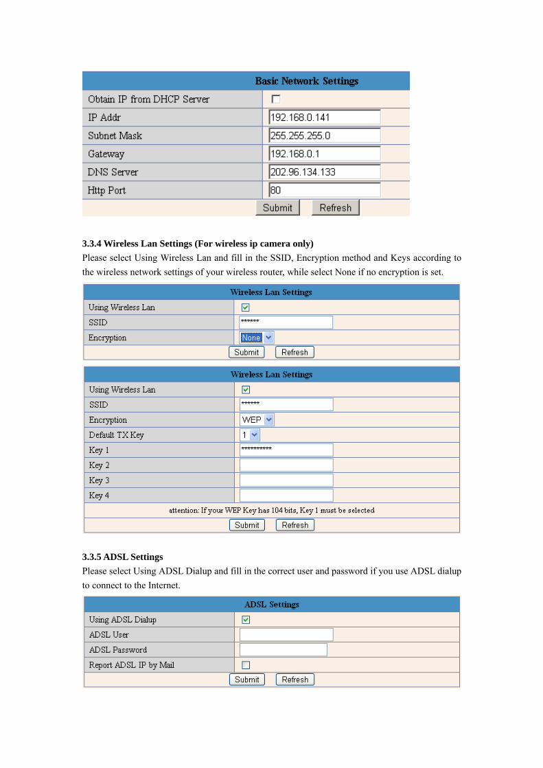
3.3.4 Wireless Lan Settings (For wireless ip camera only) Please select Using Wireless Lan and fill in the SSID, Encryption method and Keys according to the wireless network settings of your wireless router, while select None if no encryption is set.
3.3.5 ADSL Settings Please select Using ADSL Dialup and fill in the correct user and password if you use ADSL dialup to connect to the Internet.
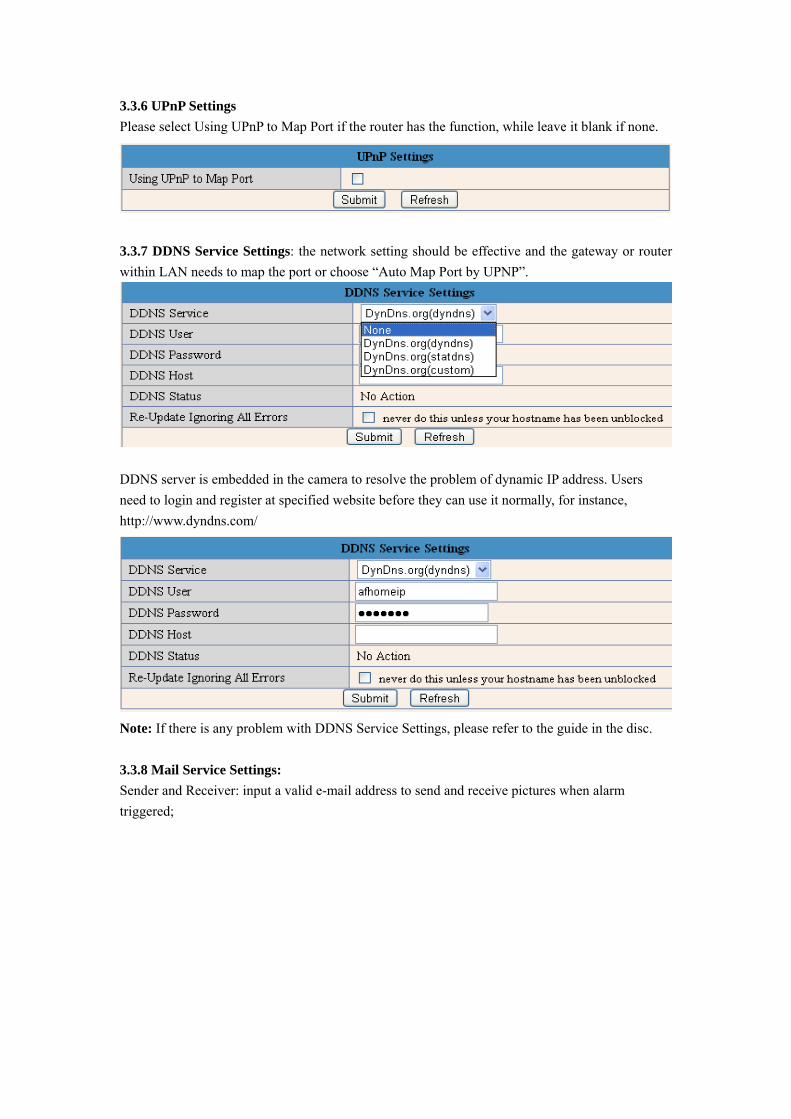
3.3.6 UPnP Settings Please select Using UPnP to Map Port if the router has the function, while leave it blank if none.
3.3.7 DDNS Service Settings: the network setting should be effective and the gateway or router within LAN needs to map the port or choose “Auto Map Port by UPNP”.
DDNS server is embedded in the camera to resolve the problem of dynamic IP address. Users need to login and register at specified website before they can use it normally, for instance, http://www.dyndns.com/
Note: If there is any problem with DDNS Service Settings, please refer to the guide in the disc. 3.3.8 Mail Service Settings: Sender and Receiver: input a valid e-mail address to send and receive pictures when alarm triggered;
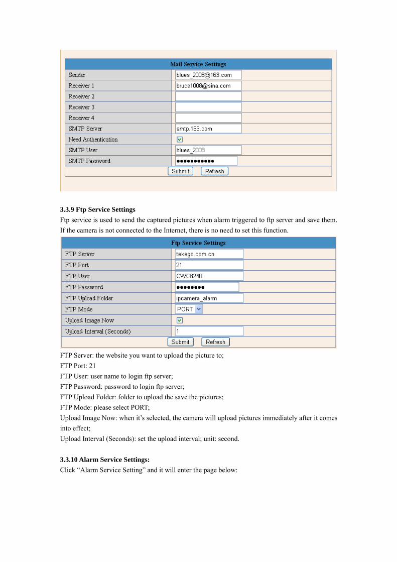
3.3.9 Ftp Service Settings Ftp service is used to send the captured pictures when alarm triggered to ftp server and save them. If the camera is not connected to the Internet, there is no need to set this function.
FTP Server: the website you want to upload the picture to; FTP Port: 21 FTP User: user name to login ftp server; FTP Password: password to login ftp server; FTP Upload Folder: folder to upload the save the pictures; FTP Mode: please select PORT; Upload Image Now: when it’s selected, the camera will upload pictures immediately after it comes into effect; Upload Interval (Seconds): set the upload interval; unit: second. 3.3.10 Alarm Service Settings: Click “Alarm Service Setting” and it will enter the page below:

Motion Detect Armed: Moving objects trigger alarm; Alarm Input Armed: Alarming signal input triggers alarm;
4 How to view on the Internet?
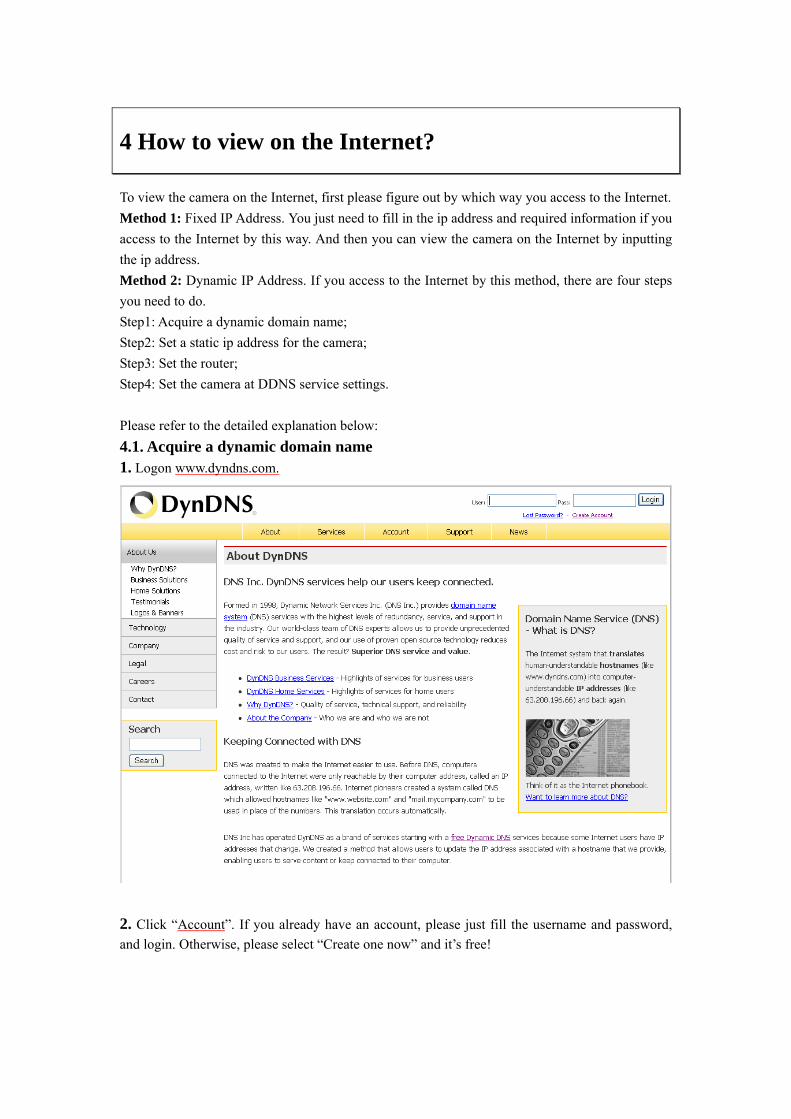
To view the camera on the Internet, first please figure out by which way you access to the Internet. Method 1: Fixed IP Address. You just need to fill in the ip address and required information if you access to the Internet by this way. And then you can view the camera on the Internet by inputting the ip address. Method 2: Dynamic IP Address. If you access to the Internet by this method, there are four steps you need to do. Step1: Acquire a dynamic domain name; Step2: Set a static ip address for the camera; Step3: Set the router; Step4: Set the camera at DDNS service settings. Please refer to the detailed explanation below: 4.1. Acquire a dynamic domain name 1. Logon www.dyndns.com.
2. Click “Account”. If you already have an account, please just fill the username and password, and login. Otherwise, please select “Create one now” and it’s free!
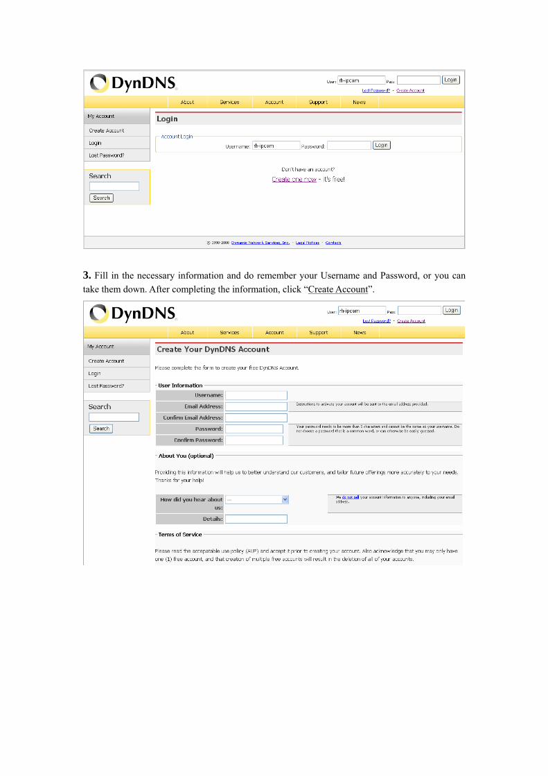
3. Fill in the necessary information and do remember your Username and Password, or you can take them down. After completing the information, click “Create Account”.
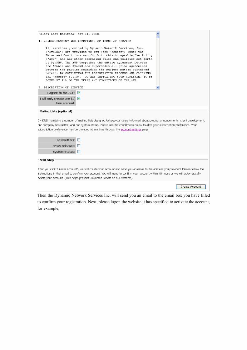
Then the Dynamic Network Services Inc. will send you an email to the email box you have filled to confirm your registration. Next, please logon the website it has specified to activate the account, for example,
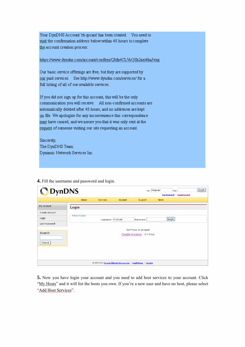
4. Fill the username and password and login.
5. Now you have login your account and you need to add host services to your account. Click “My Hosts” and it will list the hosts you own. If you’re a new user and have no host, please select “Add Host Services”.
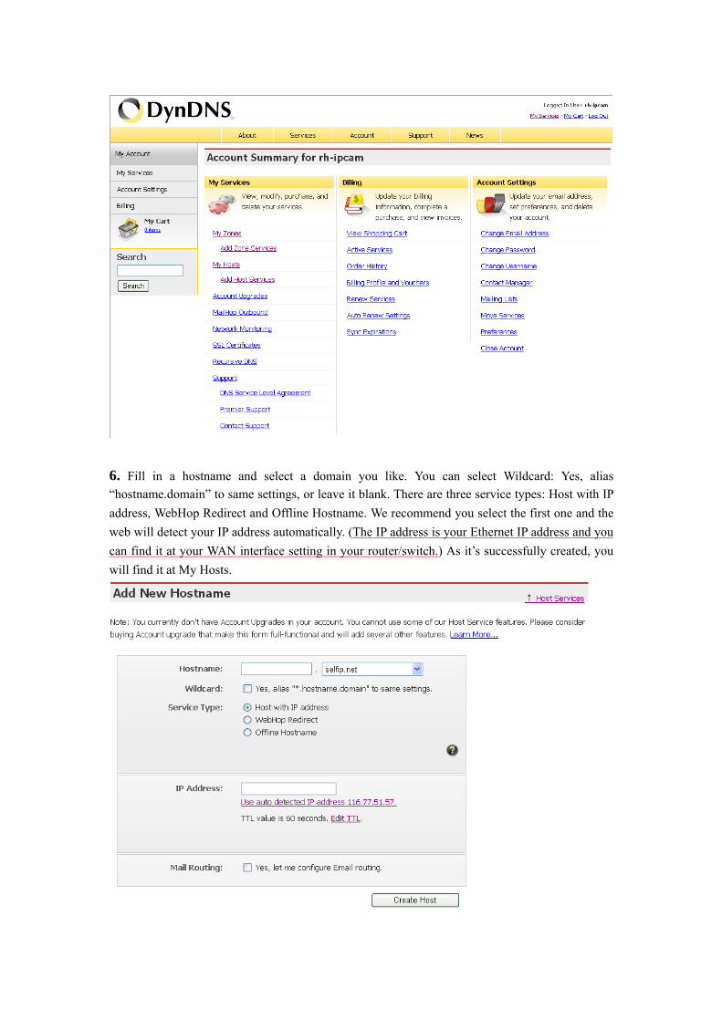
6. Fill in a hostname and select a domain you like. You can select Wildcard: Yes, alias “hostname.domain” to same settings, or leave it blank. There are three service types: Host with IP address, WebHop Redirect and Offline Hostname. We recommend you select the first one and the web will detect your IP address automatically. (The IP address is your Ethernet IP address and you can find it at your WAN interface setting in your router/switch.) As it’s successfully created, you will find it at My Hosts.
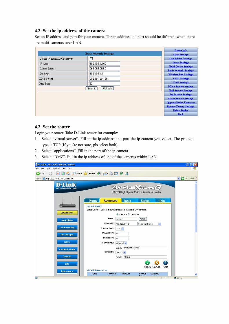
4.2. Set the ip address of the camera Set an IP address and port for your camera. The ip address and port should be different when there are multi-cameras over LAN.
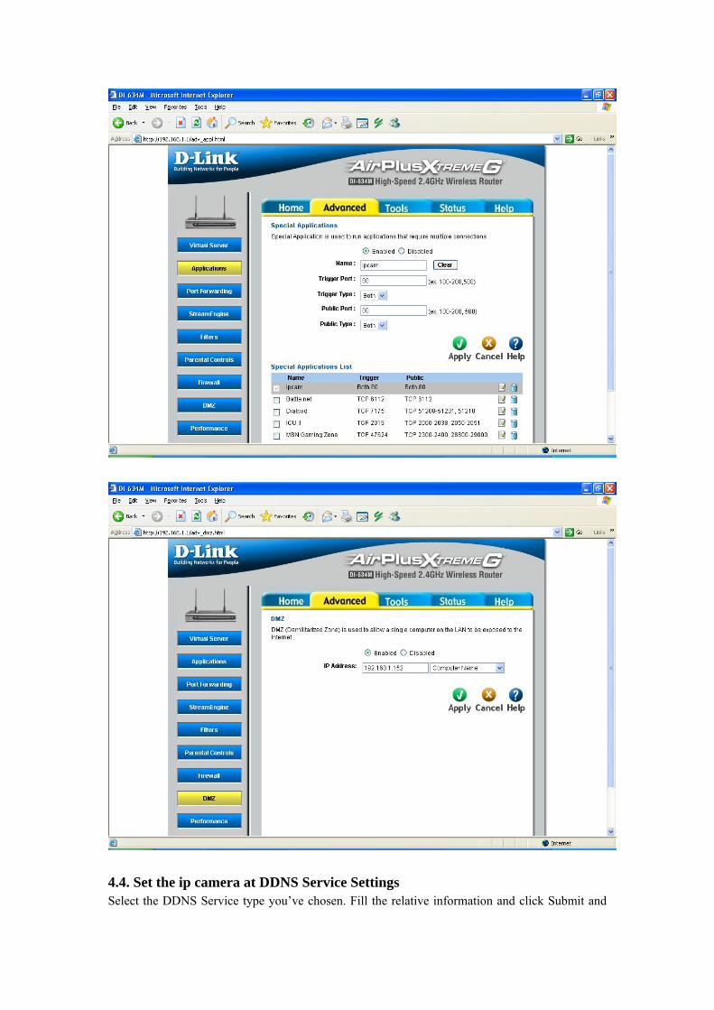
4.3. Set the router Login your router. Take D-Link router for example: 1. Select “virtual server”. Fill in the ip address and port the ip camera you’ve set. The protocol
type is TCP (If you’re not sure, pls select both). 2. Select “applications”. Fill in the port of the ip camera. 3. Select “DMZ”. Fill in the ip address of one of the cameras within LAN.
4.4. Set the ip camera at DDNS Service Settings Select the DDNS Service type you’ve chosen. Fill the relative information and click Submit and
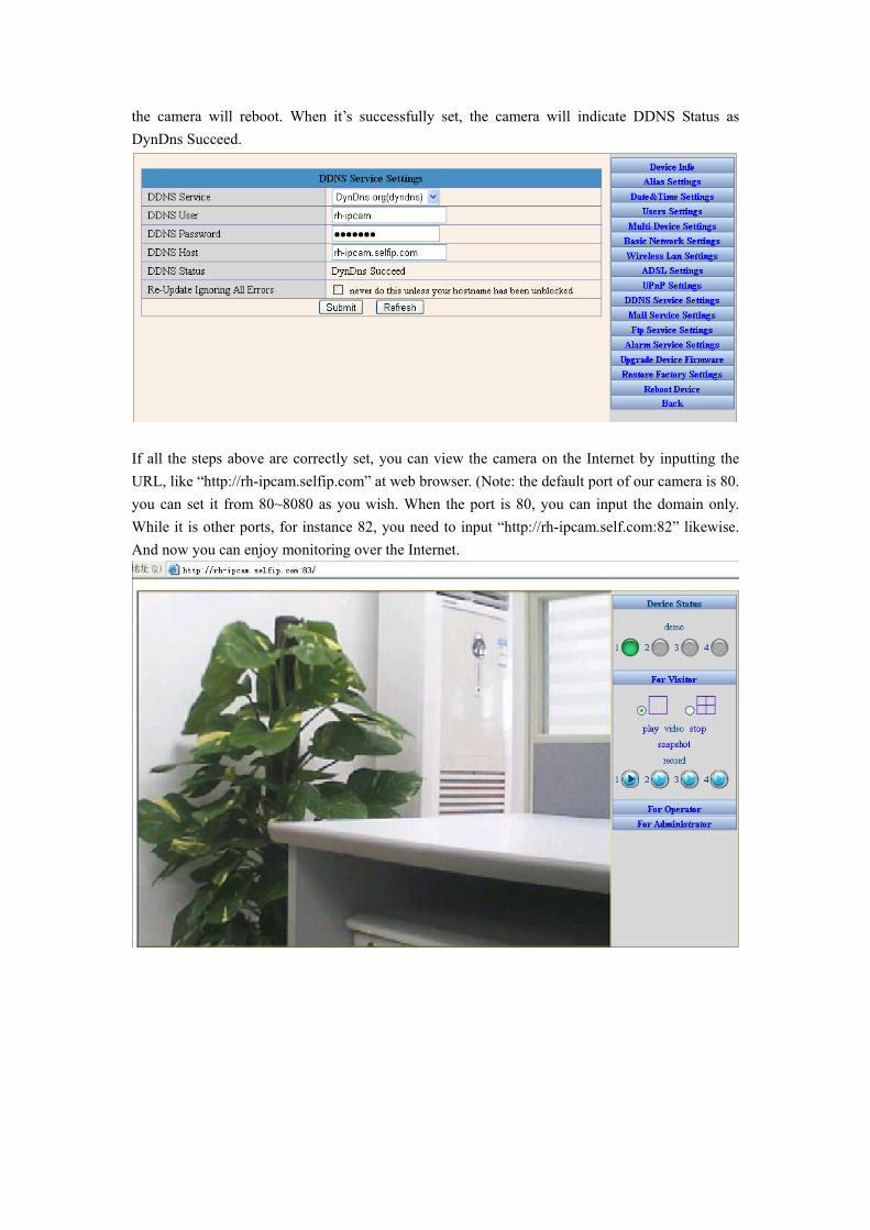
the camera will reboot. When it’s successfully set, the camera will indicate DDNS Status as DynDns Succeed.
If all the steps above are correctly set, you can view the camera on the Internet by inputting the URL, like “http://rh-ipcam.selfip.com” at web browser. (Note: the default port of our camera is 80. you can set it from 80~8080 as you wish. When the port is 80, you can input the domain only. While it is other ports, for instance 82, you need to input “http://rh-ipcam.self.com:82” likewise. And now you can enjoy monitoring over the Internet.
5 Specifications
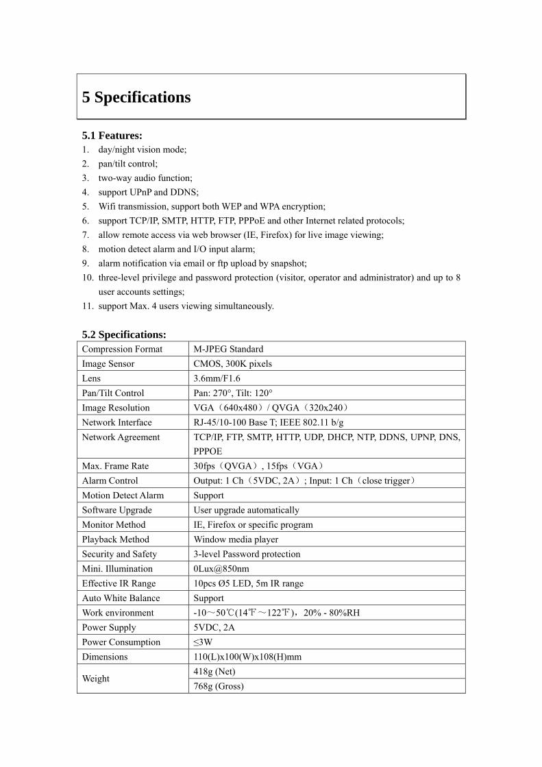
5.1 Features: 1. day/night vision mode; 2. pan/tilt control; 3. two-way audio function; 4. support UPnP and DDNS; 5. Wifi transmission, support both WEP and WPA encryption; 6. support TCP/IP, SMTP, HTTP, FTP, PPPoE and other Internet related protocols; 7. allow remote access via web browser (IE, Firefox) for live image viewing; 8. motion detect alarm and I/O input alarm; 9. alarm notification via email or ftp upload by snapshot; 10. three-level privilege and password protection (visitor, operator and administrator) and up to 8
user accounts settings; 11. support Max. 4 users viewing simultaneously. 5.2 Specifications: Compression Format M-JPEG Standard Image Sensor CMOS, 300K pixels Lens 3.6mm/F1.6 Pan/Tilt Control Pan: 270°, Tilt: 120° Image Resolution VGA(640x480)/ QVGA(320x240) Network Interface RJ-45/10-100 Base T; IEEE 802.11 b/g Network Agreement TCP/IP, FTP, SMTP, HTTP, UDP, DHCP, NTP, DDNS, UPNP, DNS,
PPPOE Max. Frame Rate 30fps(QVGA), 15fps(VGA) Alarm Control Output: 1 Ch(5VDC, 2A); Input: 1 Ch(close trigger) Motion Detect Alarm Support Software Upgrade User upgrade automatically Monitor Method IE, Firefox or specific program Playback Method Window media player Security and Safety 3-level Password protection Mini. Illumination 0Lux@850nm Effective IR Range 10pcs Ø5 LED, 5m IR range Auto White Balance Support Work environment -10~50℃(14℉~122℉),20% - 80%RH Power Supply 5VDC, 2A Power Consumption ≤3W Dimensions 110(L)x100(W)x108(H)mm
418g (Net) Weight
768g (Gross)
6 Appendix
6.1 Restore Factory Settings Under some condition, users can restore the default factory settings through web. However, when users cannot operate through web page, they may restore default factory settings as follows:
Turn off the power supply and click reset and turn on the power. All the parameters will be restored to factory settings when the green LED flashes several seconds later.
6.2 Trouble Shooting 1. Cameras cannot be found by searching program
Check the physical connection is correct or not. If the cameras are connected with PC directly, cross-over cable must be used.
2. Website cannot be opened PC and the cameras are at different net segment, or subnet mask, or the IP addresses of
the cameras conflict. For IP address of PC, it can’t be set as “get IP automatically”. 3. Website can be viewed but without images
Controls are not installed. Check the security level setting is correct or not. 4. Images cannot be viewed from remote.
Check the local gateway or router settings are correct or not, which include port, IP address mapping.
Controls are not well installed. Check the security level setting is correct or not. The firewall has some restrictions with cameras