Embed Size (px)
Citation preview
wie
tap
0820.1 C 07/13
wietap Overvoltage Protection
Tensions running high

2
wietap
wietap
3
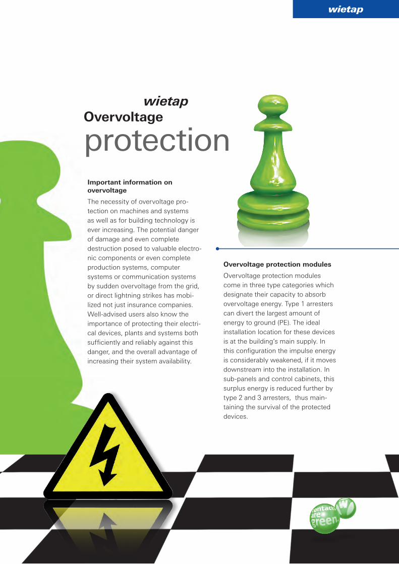
Important information on overvoltage
The necessity of overvoltage protection on machines and systems as well as for building technology is ever increasing. The potential danger of damage and even complete destruction posed to valuable electronic components or even complete production systems, computer systems or communication systems by sudden overvoltage from the grid, or direct lightning strikes has mobilized not just insurance companies. Welladvised users also know the importance of protecting their electrical devices, plants and systems both sufficiently and reliably against this danger, and the overall advantage of increasing their system availability.
Overvoltage protection modules
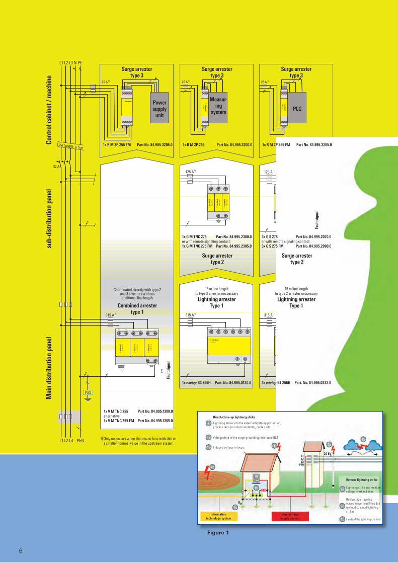
Overvoltage protection modules come in three type categories which designate their capacity to absorb overvoltage energy. Type 1 arresters can divert the largest amount of energy to ground (PE). The ideal installation location for these devices is at the building’s main supply. In this configuration the impulse energy is considerably weakened, if it moves downstream into the installation. In subpanels and control cabinets, this surplus energy is reduced further by type 2 and 3 arresters, thus maintaining the survival of the protected devices.
Overvoltage
protection
4
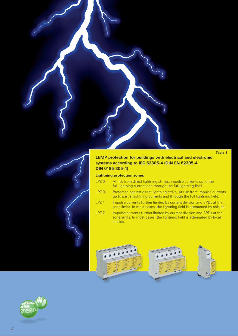
LEMP protection for buildings with electrical and electronic systems according to IEC 62305-4 (DIN EN 62305-4, DIN 0185-305-4)
Lightning protection zones
LPZ 0A At risk from direct lightning strikes, impulse currents up to the full lightning current and through the full lightning field.
LPZ 0B Protected against direct lightning strike. At risk from impulse currents up to partial lightning currents and through the full lightning field.
LPZ 1 Impulse currents further limited by current division and SPDs at the zone limits. In most cases, the lightning field is attenuated by shields.
LPZ 2 Impulse currents further limited by current division and SPDs at the zone limits. In most cases, the lightning field is attenuated by local shields.
Table 1
wietap IEC
5
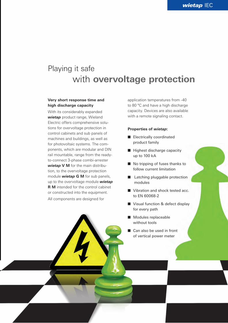
Very short response time and high discharge capacity
With its considerably expanded wietap product range, Wieland Electric offers comprehensive solutions for overvoltage protection in control cabinets and sub panels of machines and buildings, as well as for photovoltaic systems. The components, which are modular and DIN rail mountable, range from the readytoconnect 3phase combiarrester wietap V M for the main distribution, to the overvoltage protection module wietap G M for sub panels, up to the overvoltage module wietap R M intended for the control cabinet or constructed into the equipment.
All components are designed for
Playing it safe
application temperatures from 40 to 80 °C and have a high discharge capacity. Devices are also available with a remote signaling contact.
Properties of wietap:
■ Electrically coordinated product family
■ Highest discharge capacity up to 100 kA
■ No tripping of fuses thanks to follow current limitation
■ Latching pluggable protection modules
■ Vibration and shock tested acc. to EN 60068-2
■ Visual function & defect display for every path
■ Modules replaceable without tools
■ Can also be used in front of vertical power meter
with overvoltage protection
L1 L2
PEN
L3
✙
4 3
2 1
✙
✙
4 3
2 1
✙
✙✙
R M 2P 255
R M 2P 255
R M
2P
255
FM
R M
2P
255
FM
R M
2P
255
FM
N/PE(N)
L/N
N/PE(N)
L/N
N/PE(N)
L/N
N/PE(N)
R M
2P
255
FM
R M
2P
255
FM
R M
2P
255
FM
L1 L1’
PEN
L2
✙
B3 225 H
N/PE(N)N/PE(N)N/PE(N)
L2’ L3 L3’
25 A25 A
125 A
25 A
125 A
PAS
L1 L2 L3 N PE
1) 1) 1)
1) 1)
315 A 315 A1) 1)
L1 L2 L3 N PE
1234
L1 L1´ L2 L2´
PEN
L3 L3´
✙
V M
TN
C 25
5 FM
V M
TN
C 25
5 FM
V M
TN
C 25
5 FM
315 A 1)
L’L
B1 255H
L’L
B1 255H
L’L
B1 255H
L’L
B1 255H
6
1) Only necessary when there is no fuse with this or a smaller nominal value in the upstream system.
3x wietap B1 255H Part. No. 84.995.0222.01x wietap B3 255H Part. No. 84.995.0120.0
Faul
t sig
nal
1x V M TNC 255 Part No. 84.995.1300.0alternative1x V M TNC 255 FM Part No. 84.995.1305.0
1x R M 2P 255 FM Part No. 84.995.3205.0 1x R M 2P 255 Part No. 84.995.3200.0 1x R M 2P 255 FM Part No. 84.995.3205.0
Faul
t sig
nal
Combined arrestertype 1
Coordinated directly with type 2 and 3 arresters without additional line length
Line length ≥ 5 m
Surge arrestertype 2
Surge arrestertype 2
Mai
n di
strib
utio
n pa
nel
sub-
dist
ribut
ion
pane
lCo
ntro
l cab
inet
/ m
achi
ne
Surge arrestertype 3
Surge arrestertype 3
Surge arrestertype 3
3x G S 275 Part No. 84.995.2070.0 or with remote signaling contact:3x G S 275 FM Part No. 84.995.2090.0
1x G M TNC 275 Part No. 84.995.2300.0 or with remote signaling contact:1x G M TNC 275 FM Part No. 84.995.2305.0
Power supply
unit
Measur-ing
system PLC
Figure 1
Information technology system
Low-voltage supply system
Remote lightning strike
Lightning strike into medium voltage overhead lines
Overvoltage traveling waves in overhead lines due to cloud-to-cloud lightning strikes
Fields of the lightning channel
Direct/close-up lightning strike
Lightning strike into the external lightning protection, process rack (in industrial plants), cables, etc.
Voltage drop of the surge grounding resistance RST
Induced voltage in loops
15 m line length to type 2 arrester neccessary
Lightning arresterType 1
15 m line length to type 2 arrester neccessary
Lightning arresterType 1
wietap IEC
➀ ➁
7
Overvoltage protection
The zone concept for lightning protection
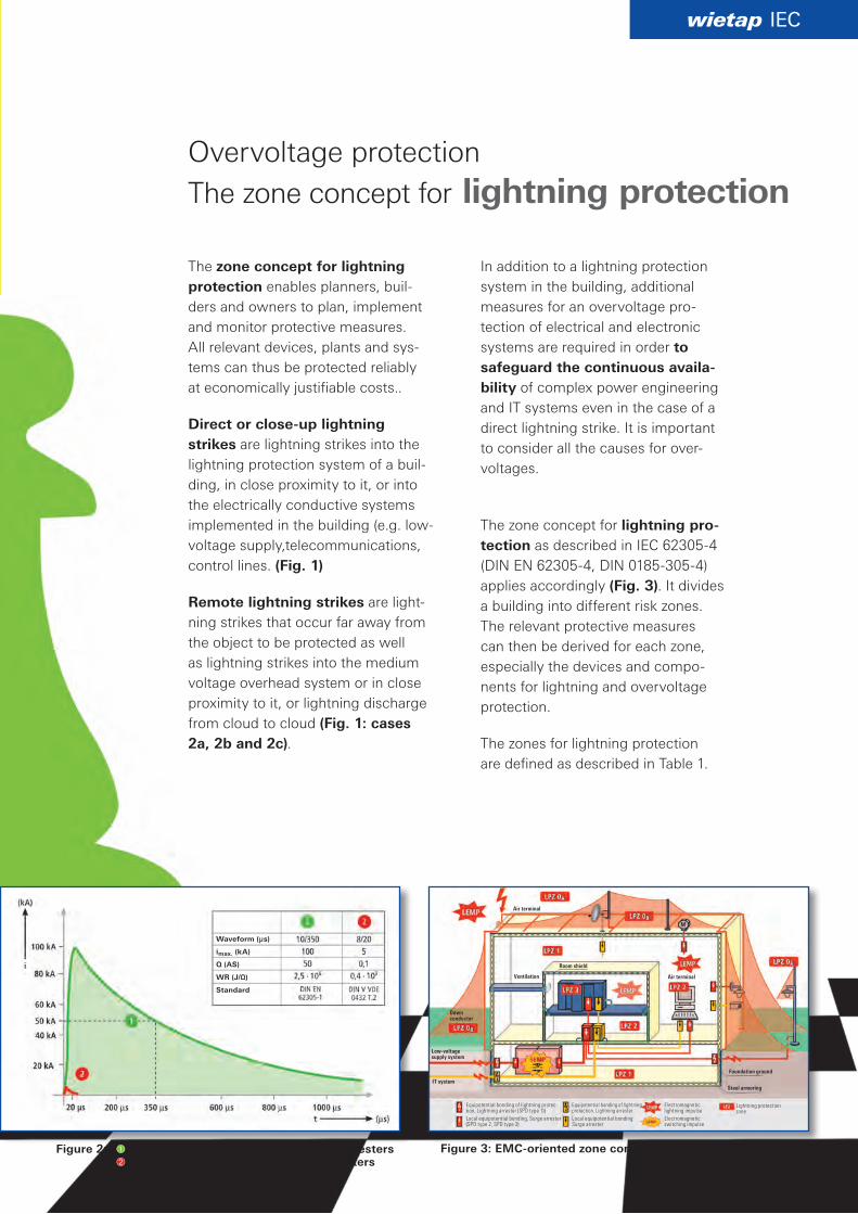
The zone concept for lightning protection enables planners, builders and owners to plan, implement and monitor protective measures. All relevant devices, plants and systems can thus be protected reliably at economically justifiable costs..
Direct or close-up lightning strikes are lightning strikes into the lightning protection system of a building, in close proximity to it, or into the electrically conductive systems implemented in the building (e.g. lowvoltage supply,telecommunications, control lines. (Fig. 1)
Remote lightning strikes are lightning strikes that occur far away from the object to be protected as well as lightning strikes into the medium voltage overhead system or in close proximity to it, or lightning discharge from cloud to cloud (Fig. 1: cases 2a, 2b and 2c).
In addition to a lightning protection system in the building, additional measures for an overvoltage protection of electrical and electronic systems are required in order to safeguard the continuous availa-bility of complex power engineering and IT systems even in the case of a direct lightning strike. It is important to consider all the causes for overvoltages.
The zone concept for lightning pro-tection as described in IEC 623054 (DIN EN 623054, DIN 01853054) applies accordingly (Fig. 3). It divides a building into different risk zones. The relevant protective measures can then be derived for each zone, especially the devices and components for lightning and overvoltage protection.
The zones for lightning protection are defined as described in Table 1.
Waveform (µs)
imax. (kA)
Q (AS)
WR (J/Ω)
Standard
Figure 3: EMC-oriented zone concept for lightning protection Figure 2: Peak current for testing of lightning arresters Peak current for testing of surge arresters
Equipotential bonding of lightning protec-tion, Lightning arrester (SPD type 1))Local equipotential bonding, Surge arrester (SPD type 2, SPD type 3)
Air terminal
Ventilation
Room shield
Air terminal
Foundation ground
Steel armoring
Down conductor
Low-voltage supply system
IT system
Equipotential bonding of lightning protection, Lightning arresterLocal equipotential bonding Surge arrester
Electromagneticlightning impulseElectromagneticswitching impulse
Lightning protection zone
AöK
AöK
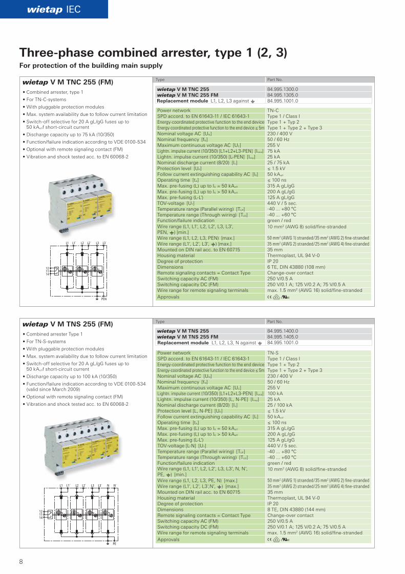
wietap V M TNC 255 (FM)
wietap V M TNS 255 (FM)
wietap IEC
wietap V M TNC 255 84.995.1300.0wietap V M TNC 255 FM 84.995.1305.0
84.995.1001.0
wietap V M TNS 255 84.995.1400.0wietap V M TNS 255 FM 84.995.1405.0
84.995.1001.0
8
• Combined arrester, type 1
• For TNCsystems
• With pluggable protection modules
• Max. system availability due to follow current limitation
• Switchoff selective for 20 A gL/gG fuses up to 50 kAefff shortcircuit current
• Discharge capacity up to 75 kA (10/350)
• Function/failure indication according to VDE 0100534
• Optional with remote signaling contact (FM)
• Vibration and shock tested acc. to EN 600682
• Combined arrester Type 1
• For TNSsystems
• With pluggable protection modules
• Max. system availability due to follow current limitation
• Switchoff selective for 20 A gL/gG fuses up to 50 kAefff shortcircuit current
• Discharge capacity up to 100 kA (10/350)
• Function/failure indication according to VDE 0100534 (valid since March 2009)
• Optional with remote signaling contact (FM)
• Vibration and shock tested acc. to EN 600682
Type Part No.
Type Part No.
Power network TNCSPD accord. to EN 6164311 / IEC 616431 Type 1 / Class IEnergycoordinated protective function to the end device Type 1 + Typ 2Energycoordinated protective function to the end device ≤ 5m Type 1 + Type 2 + Type 3Nominal voltage AC [UN] 230 / 400 VNominal frequency [fN] 50 / 60 HzMaximum continuous voltage AC [UC] 255 VLightn. impulse current (10/350) [L1+L2+L3PEN] [Itotal] 75 kALightn. impulse current (10/350) [LPEN] [Iimp] 25 kANominal discharge current (8/20) [In] 25 / 75 kAProtection level [UP] ≤ 1.5 kVFollow current extinguishing capability AC [Ifi] 50 kAeff
Operating time [tA] ≤ 100 nsMax. prefusing (L) up to IK = 50 kAeff 315 A gL/gGMax. prefusing (L) up to IK > 50 kAeff 200 A gL/gGMax. prefusing (LL') 125 A gL/gGTOVvoltage [UT] 440 V / 5 sec.Temperature range (Parallel wiring) [TUP] 40 ... +80 °C Temperature range (Through wiring) [TUS] 40 ... +60 °C Function/failure indication green / redWire range (L1, L1', L2, L2', L3, L3', PEN, e) [min.]
10 mm2 (AWG 8) solid/finestranded
Wire range (L1, L2, L3, PEN) [max.] 50 mm2 (AWG 1) stranded/35 mm2 (AWG 2) fine-stranded Wire range (L1', L2', L3', e) [max.] 35 mm2 (AWG 2) stranded/25 mm2 (AWG 4) fine-stranded Mounted on DIN rail acc. to EN 60715 35 mm Housing material Thermoplast, UL 94 V0Degree of protection IP 20 Dimensions 6 TE, DIN 43880 (108 mm)Remote signaling contacts = Contact Type Changeover contactSwitching capacity AC (FM) 250 V/0.5 A Switching capacity DC (FM) 250 V/0.1 A; 125 V/0.2 A; 75 V/0.5 A Wire range for remote signaling terminals max. 1.5 mm2 (AWG 16) solid/finestrandedApprovals
Power network TNSSPD accord. to EN 6164311 / IEC 616431 Type 1 / Class IEnergycoordinated protective function to the end device Type 1 + Typ 2Energycoordinated protective function to the end device ≤ 5m Type 1 + Type 2 + Type 3Nominal voltage AC [UN] 230 / 400 VNominal frequency [fN] 50 / 60 HzMaximum continuous voltage AC [UC] 255 VLightn. impulse current (10/350) [L1+L2+L3PEN] [Itotal] 100 kALightn. impulse current (10/350) [L, NPE] [Iimp] 25 kANominal discharge current (8/20) [In] 25 / 100 kAProtection level [L, NPE] [UP] ≤ 1.5 kVFollow current extinguishing capability AC [Ifi] 50 kAeff
Operating time [tA] ≤ 100 nsMax. prefusing (L) up to IK = 50 kAeff 315 A gL/gGMax. prefusing (L) up to IK > 50 kAeff 200 A gL/gGMax. prefusing (LL') 125 A gL/gGTOVvoltage [LN] [UT] 440 V / 5 sec.Temperature range (Parallel wiring) [TUP] 40 ... +80 °C Temperature range (Through wiring) [TUS] 40 ... +60 °C Function/failure indication green / redWire range (L1, L1’, L2, L2’, L3, L3’, N, N’, PE, e) [min.]
10 mm2 (AWG 8) solid/finestranded
Wire range (L1, L2, L3, PE, N) [max.] 50 mm2 (AWG 1) stranded/35 mm2 (AWG 2) fine-stranded Wire range (L1', L2', L3',N’, e) [max.] 35 mm2 (AWG 2) stranded/25 mm2 (AWG 4) fine-stranded Mounted on DIN rail acc. to EN 60715 35 mm Housing material Thermoplast, UL 94 V0Degree of protection IP 20 Dimensions 8 TE, DIN 43880 (144 mm)Remote signaling contacts = Contact Type Changeover contact Switching capacity AC (FM) 250 V/0.5 A Switching capacity DC (FM) 250 V/0.1 A; 125 V/0.2 A; 75 V/0.5 A Wire range for remote signaling terminals max. 1.5 mm2 (AWG 16) solid/finestrandedApprovals
Three-phase combined arrester, type 1 (2, 3)For protection of the building main supply
Replacement module L1, L2, L3 against e
Replacement module L1, L2, L3, N against e
AöK
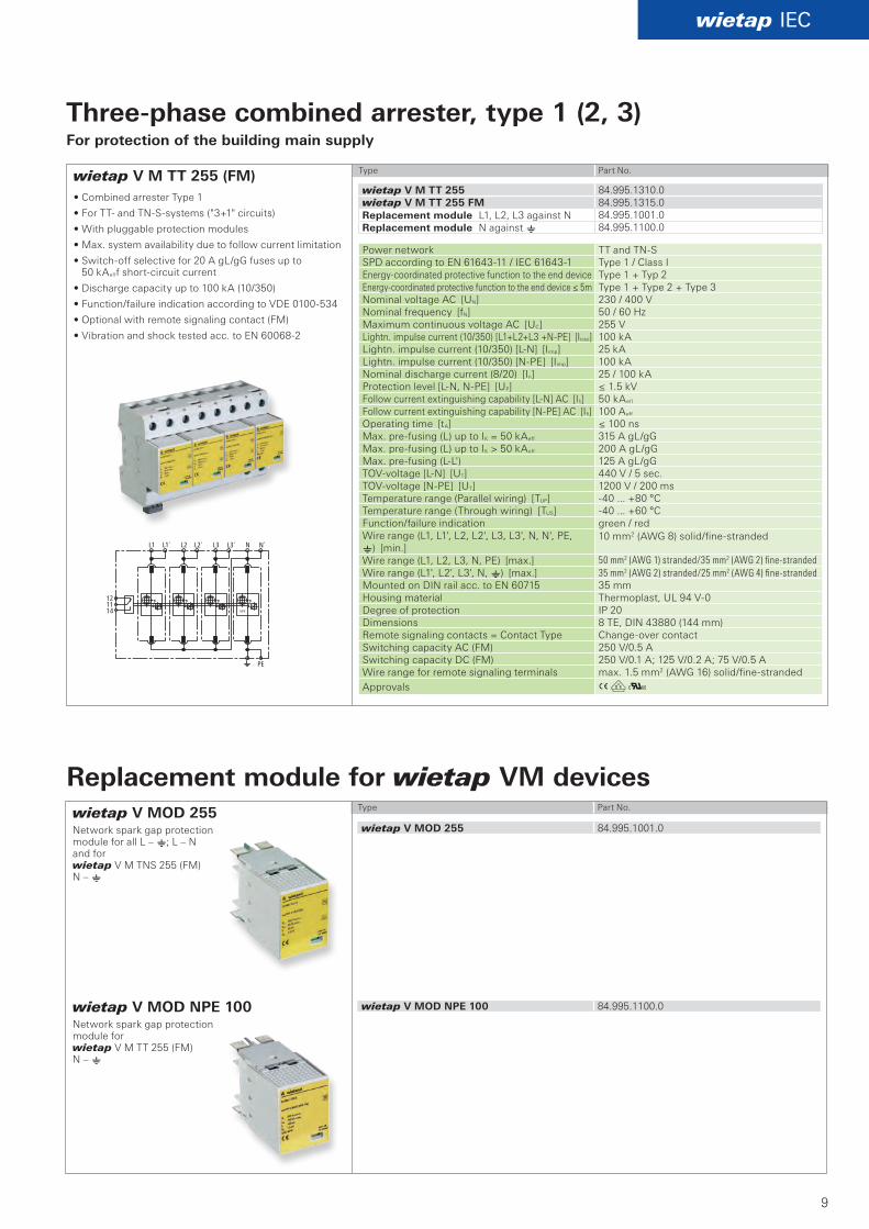
wietap V M TT 255 (FM)
wietap IEC
wietap V M TT 255 84.995.1310.0wietap V M TT 255 FM 84.995.1315.0
84.995.1001.084.995.1100.0
wietap V MOD 255 84.995.1001.0
wietap V MOD NPE 100 84.995.1100.0
9
• Combined arrester Type 1
• For TT and TNSsystems ("3+1" circuits)
• With pluggable protection modules
• Max. system availability due to follow current limitation
• Switchoff selective for 20 A gL/gG fuses up to 50 kAefff shortcircuit current
• Discharge capacity up to 100 kA (10/350)
• Function/failure indication according to VDE 0100534
• Optional with remote signaling contact (FM)
• Vibration and shock tested acc. to EN 600682
Type Part No.
Type Part No.
Power network TT and TNSSPD according to EN 6164311 / IEC 616431 Type 1 / Class IEnergycoordinated protective function to the end device Type 1 + Typ 2Energycoordinated protective function to the end device ≤ 5m Type 1 + Type 2 + Type 3Nominal voltage AC [UN] 230 / 400 VNominal frequency [fN] 50 / 60 HzMaximum continuous voltage AC [UC] 255 VLightn. impulse current (10/350) [L1+L2+L3 +NPE] [Itotal] 100 kALightn. impulse current (10/350) [LN] [Iimp] 25 kALightn. impulse current (10/350) [NPE] [Iimp] 100 kANominal discharge current (8/20) [In] 25 / 100 kAProtection level [LN, NPE] [UP] ≤ 1.5 kVFollow current extinguishing capability [LN] AC [Ifi] 50 kAeff
Follow current extinguishing capability [NPE] AC [Ifi] 100 Aeff
Operating time [tA] ≤ 100 nsMax. prefusing (L) up to IK = 50 kAeff 315 A gL/gGMax. prefusing (L) up to IK > 50 kAeff 200 A gL/gGMax. prefusing (LL') 125 A gL/gGTOVvoltage [LN] [UT] 440 V / 5 sec.TOVvoltage [NPE] [UT] 1200 V / 200 msTemperature range (Parallel wiring) [TUP] 40 ... +80 °C Temperature range (Through wiring) [TUS] 40 ... +60 °C Function/failure indication green / redWire range (L1, L1', L2, L2', L3, L3', N, N', PE, e) [min.]
10 mm2 (AWG 8) solid/finestranded
Wire range (L1, L2, L3, N, PE) [max.] 50 mm2 (AWG 1) stranded/35 mm2 (AWG 2) fine-stranded Wire range (L1', L2', L3', N, e) [max.] 35 mm2 (AWG 2) stranded/25 mm2 (AWG 4) fine-stranded Mounted on DIN rail acc. to EN 60715 35 mm Housing material Thermoplast, UL 94 V0Degree of protection IP 20 Dimensions 8 TE, DIN 43880 (144 mm)Remote signaling contacts = Contact Type Changeover contact Switching capacity AC (FM) 250 V/0.5 A Switching capacity DC (FM) 250 V/0.1 A; 125 V/0.2 A; 75 V/0.5 AWire range for remote signaling terminals max. 1.5 mm2 (AWG 16) solid/finestrandedApprovals
Three-phase combined arrester, type 1 (2, 3)For protection of the building main supply
Replacement module L1, L2, L3 against NReplacement module N against e
wietap V MOD NPE 100Network spark gap protection module for wietap V M TT 255 (FM) N – e
wietap V MOD 255Network spark gap protection module for all L – e; L – N and for wietap V M TNS 255 (FM) N – e
Replacement module for wietap VM devices
Aö
Aö
wietap B1 255H
wietap B3 255H
wietap IEC
N/PEN
L1 L2 L3
wietap B3 255H 84.995.0120.0
wietap B1 255H 84.995.0222.0
N/PENN´/PEN
L L´
10
Type Part No.
Type Part No.
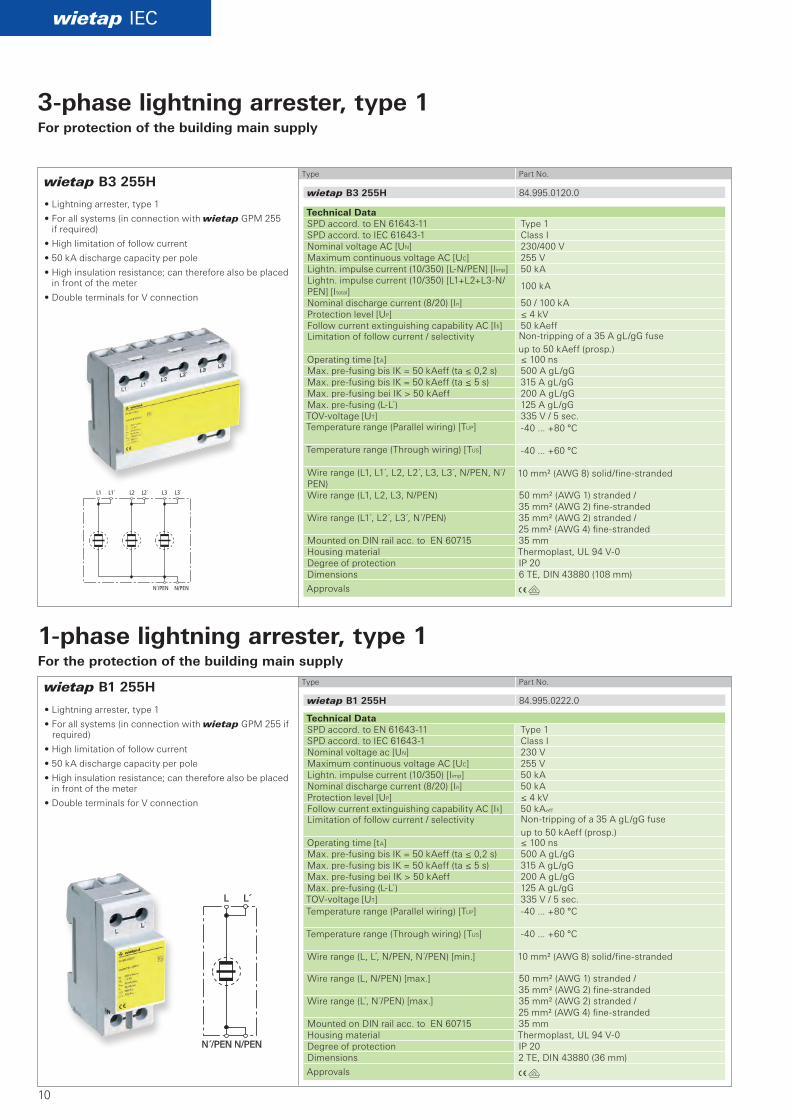
• Lightning arrester, type 1
• For all systems (in connection with wietap GPM 255 if required)
• High limitation of follow current
• 50 kA discharge capacity per pole
• High insulation resistance; can therefore also be placed in front of the meter
• Double terminals for V connection
Technical Data SPD accord. to EN 6164311 Type 1 SPD accord. to IEC 616431 Class I Nominal voltage AC [UN] 230/400 V Maximum continuous voltage AC [UC] 255 V Lightn. impulse current (10/350) [LN/PEN] [Iimp] 50 kA Lightn. impulse current (10/350) [L1+L2+L3N/PEN] [Itotal]
100 kA
Nominal discharge current (8/20) [In] 50 / 100 kA Protection level [UP] ≤ 4 kV Follow current extinguishing capability AC [Ifi] 50 kAeff Limitation of follow current / selectivity Nontripping of a 35 A gL/gG fuse
up to 50 kAeff (prosp.) Operating time [tA] ≤ 100 ns Max. prefusing bis IK = 50 kAeff (ta ≤ 0,2 s) 500 A gL/gG Max. prefusing bis IK = 50 kAeff (ta ≤ 5 s) 315 A gL/gG Max. prefusing bei IK > 50 kAeff 200 A gL/gG Max. prefusing (LL ) 125 A gL/gG TOVvoltage [UT] 335 V / 5 sec. Temperature range (Parallel wiring) [TUP] 40 ... +80 °C
Temperature range (Through wiring) [TUS] 40 ... +60 °C
Wire range (L1, L1 , L2, L2 , L3, L3 , N/PEN, N /PEN)
10 mm² (AWG 8) solid/finestranded
Wire range (L1, L2, L3, N/PEN) 50 mm² (AWG 1) stranded / 35 mm² (AWG 2) finestranded
Wire range (L1 , L2 , L3 , N /PEN) 35 mm² (AWG 2) stranded / 25 mm² (AWG 4) finestranded
Mounted on DIN rail acc. to EN 60715 35 mmHousing material Thermoplast, UL 94 V0Degree of protection IP 20 Dimensions 6 TE, DIN 43880 (108 mm)
Approvals
Technical Data SPD accord. to EN 6164311 Type 1 SPD accord. to IEC 616431 Class I Nominal voltage ac [UN] 230 V Maximum continuous voltage AC [UC] 255 V Lightn. impulse current (10/350) [Iimp] 50 kA Nominal discharge current (8/20) [In] 50 kA Protection level [UP] ≤ 4 kV Follow current extinguishing capability AC [Ifi] 50 kAeff Limitation of follow current / selectivity Nontripping of a 35 A gL/gG fuse
up to 50 kAeff (prosp.) Operating time [tA] ≤ 100 ns Max. prefusing bis IK = 50 kAeff (ta ≤ 0,2 s) 500 A gL/gG Max. prefusing bis IK = 50 kAeff (ta ≤ 5 s) 315 A gL/gG Max. prefusing bei IK > 50 kAeff 200 A gL/gG Max. prefusing (LL ) 125 A gL/gG TOVvoltage [UT] 335 V / 5 sec. Temperature range (Parallel wiring) [TUP] 40 ... +80 °C
Temperature range (Through wiring) [TUS] 40 ... +60 °C
Wire range (L, L , N/PEN, N /PEN) [min.] 10 mm² (AWG 8) solid/finestranded
Wire range (L, N/PEN) [max.] 50 mm² (AWG 1) stranded / 35 mm² (AWG 2) finestranded
Wire range (L , N /PEN) [max.] 35 mm² (AWG 2) stranded / 25 mm² (AWG 4) finestranded
Mounted on DIN rail acc. to EN 60715 35 mmHousing material Thermoplast, UL 94 V0Degree of protection IP 20 Dimensions 2 TE, DIN 43880 (36 mm)
Approvals
3-phase lightning arrester, type 1For protection of the building main supply
1-phase lightning arrester, type 1For the protection of the building main supply
• Lightning arrester, type 1
• For all systems (in connection with wietap GPM 255 if required)
• High limitation of follow current
• 50 kA discharge capacity per pole
• High insulation resistance; can therefore also be placed in front of the meter
• Double terminals for V connection
Aö
wietap GMP 255
wietap IEC
N N´
N
NPE
wietap GPM 255 84.995.0055.0
11
Type Part No.
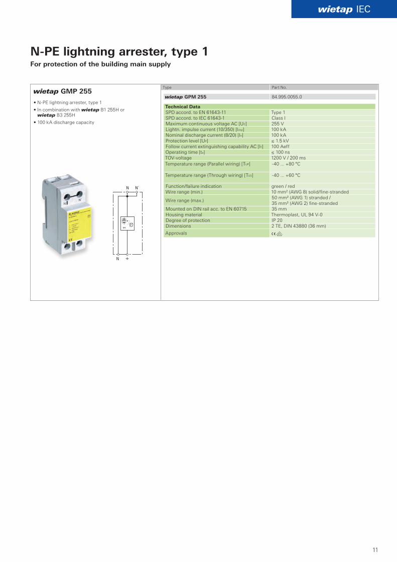
Technical Data SPD accord. to EN 6164311 Type 1 SPD accord. to IEC 616431 Class I Maximum continuous voltage AC [UC] 255 V Lightn. impulse current (10/350) [limp] 100 kA Nominal discharge current (8/20) [In] 100 kA Protection level [UP] ≤ 1.5 kV Follow current extinguishing capability AC [lfi] 100 Aeff Operating time [ta] ≤ 100 ns TOVvoltage 1200 V / 200 msTemperature range (Parallel wiring) [TUP] 40 ... +80 °C
Temperature range (Through wiring) [TUS] 40 ... +60 °C
Function/failure indication green / red Wire range (min.) 10 mm² (AWG 8) solid/finestranded
Wire range (max.) 50 mm² (AWG 1) stranded / 35 mm² (AWG 2) finestranded
Mounted on DIN rail acc. to EN 60715 35 mmHousing material Thermoplast, UL 94 V0Degree of protection IP 20 Dimensions 2 TE, DIN 43880 (36 mm)
Approvals
N-PE lightning arrester, type 1For protection of the building main supply
• NPE lightning arrester, type 1
• In combination with wietap B1 255H or wietap B3 255H
• 100 kA discharge capacity
AöK
AöK
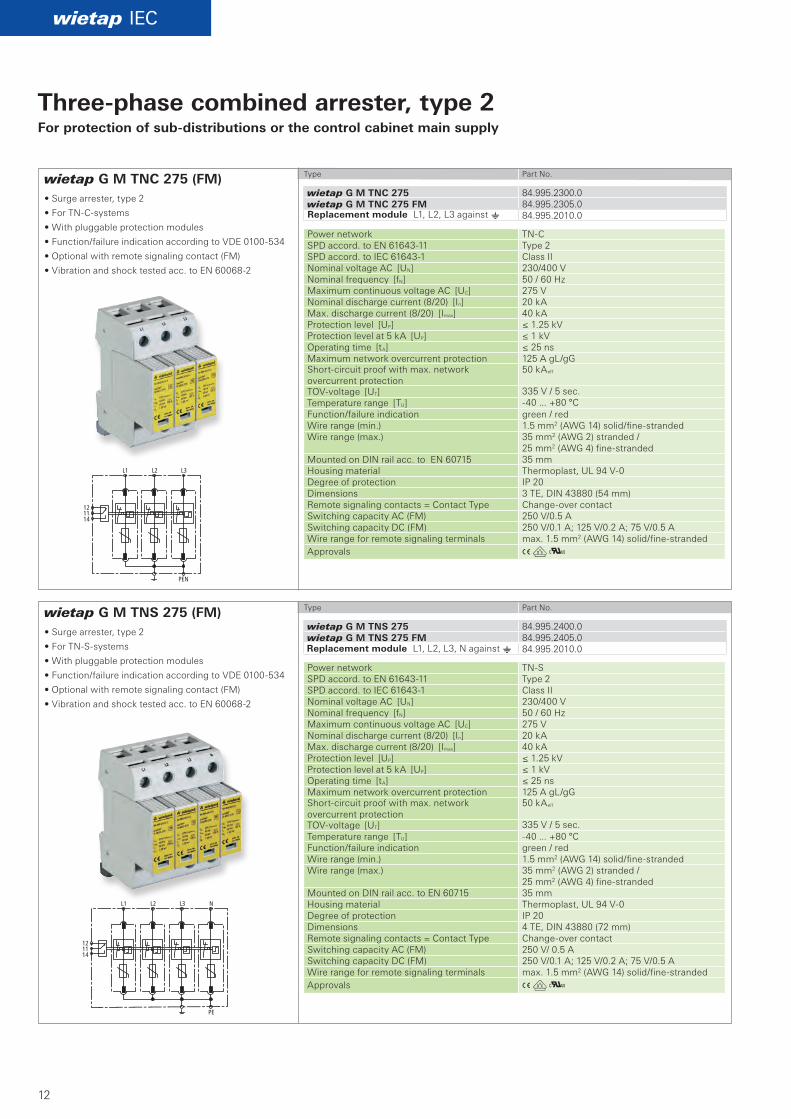
wietap G M TNC 275 (FM)
wietap G M TNS 275 (FM)
wietap IEC
wietap G M TNC 275 84.995.2300.0wietap G M TNC 275 FM 84.995.2305.0
84.995.2010.0
wietap G M TNS 275 84.995.2400.0wietap G M TNS 275 FM 84.995.2405.0
84.995.2010.0
12
Three-phase combined arrester, type 2For protection of sub-distributions or the control cabinet main supply
• Surge arrester, type 2
• For TNCsystems
• With pluggable protection modules
• Function/failure indication according to VDE 0100534
• Optional with remote signaling contact (FM)
• Vibration and shock tested acc. to EN 600682
• Surge arrester, type 2
• For TNSsystems
• With pluggable protection modules
• Function/failure indication according to VDE 0100534
• Optional with remote signaling contact (FM)
• Vibration and shock tested acc. to EN 600682
Type Part No.
Type Part No.
Power network TNCSPD accord. to EN 6164311 Type 2 SPD accord. to IEC 616431 Class II Nominal voltage AC [UN] 230/400 V Nominal frequency [fN] 50 / 60 HzMaximum continuous voltage AC [UC] 275 V Nominal discharge current (8/20) [In] 20 kA Max. discharge current (8/20) [Imax] 40 kA Protection level [UP] ≤ 1.25 kV Protection level at 5 kA [UP] ≤ 1 kV Operating time [tA] ≤ 25 ns Maximum network overcurrent protection 125 A gL/gG Shortcircuit proof with max. network overcurrent protection
50 kAeff
TOVvoltage [UT] 335 V / 5 sec. Temperature range [TU] 40 ... +80 °C Function/failure indication green / red Wire range (min.) 1.5 mm2 (AWG 14) solid/finestranded Wire range (max.) 35 mm2 (AWG 2) stranded /
25 mm2 (AWG 4) finestranded Mounted on DIN rail acc. to EN 60715 35 mm Housing material Thermoplast, UL 94 V0Degree of protection IP 20 Dimensions 3 TE, DIN 43880 (54 mm)Remote signaling contacts = Contact Type Changeover contact Switching capacity AC (FM) 250 V/0.5 A Switching capacity DC (FM) 250 V/0.1 A; 125 V/0.2 A; 75 V/0.5 A Wire range for remote signaling terminals max. 1.5 mm2 (AWG 14) solid/finestranded Approvals
Power network TNSSPD accord. to EN 6164311 Type 2 SPD accord. to IEC 616431 Class II Nominal voltage AC [UN] 230/400 V Nominal frequency [fN] 50 / 60 HzMaximum continuous voltage AC [UC] 275 V Nominal discharge current (8/20) [In] 20 kA Max. discharge current (8/20) [Imax] 40 kA Protection level [UP] ≤ 1.25 kV Protection level at 5 kA [UP] ≤ 1 kV Operating time [tA] ≤ 25 ns Maximum network overcurrent protection 125 A gL/gG Shortcircuit proof with max. network overcurrent protection
50 kAeff
TOVvoltage [UT] 335 V / 5 sec. Temperature range [TU] 40 ... +80 °C Function/failure indication green / red Wire range (min.) 1.5 mm2 (AWG 14) solid/finestranded Wire range (max.) 35 mm2 (AWG 2) stranded /
25 mm2 (AWG 4) finestranded Mounted on DIN rail acc. to EN 60715 35 mm Housing material Thermoplast, UL 94 V0Degree of protection IP 20 Dimensions 4 TE, DIN 43880 (72 mm)Remote signaling contacts = Contact Type Changeover contact Switching capacity AC (FM) 250 V/ 0.5 A Switching capacity DC (FM) 250 V/0.1 A; 125 V/0.2 A; 75 V/0.5 A Wire range for remote signaling terminals max. 1.5 mm2 (AWG 14) solid/finestrandedApprovals
Replacement module L1, L2, L3 against e
Replacement module L1, L2, L3, N against e
AöK
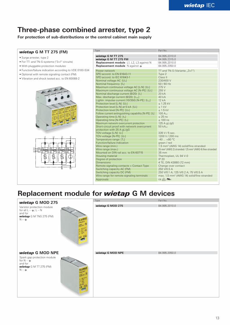
wietap G M TT 275 (FM)
wietap IEC
wietap G M TT 275 84.995.2310.0wietap G M TT 275 FM 84.995.2315.0
84.995.2010.084.995.2050.0
wietap G MOD 275 84.995.2010.0
wietap G MOD NPE 84.995.2050.0
13
Three-phase combined arrester, type 2For protection of sub-distributions or the control cabinet main supply
• Surge arrester, type 2
• For TT and TNSsystems ("3+1" circuits)
• With pluggable protection modules
• Function/failure indication according to VDE 0100534
• Optional with remote signaling contact (FM)
• Vibration and shock tested acc. to EN 600682
Type Part No.
Type Part No.
Power network TT and TNS (Variante „3+1“)SPD accord. to EN 6164311 Type 2 SPD accord. to IEC 616431 Class II Nominal voltage AC [UN] 230/400 V Nominal frequency [fN] 50 / 60 HzMaximum continuous voltage AC [LN] [UC] 275 V Maximum continuous voltage AC [NPE] [UC] 255 V Nominal discharge current (8/20) [In] 20 kA Max. discharge current (8/20) [Imax] 40 kA Lightn. impulse current (10/350) [NPE] [Iimp] 12 kA Protection level [LN] [UP] ≤ 1.25 kV Protection level [LN] at 5 kA [UP] ≤ 1 kV Protection level [NPE] [UP] ≤ 1.5 kV Follow current extinguishing capability [NPE] [Ifi] 100 Aeff Operating time [LN] [tA] ≤ 25 ns Operating time [NPE] [tA] ≤ 100 ns Maximum network overcurrent protection 125 A gL/gG Shortcircuit proof with network overcurrent protection with 25 A gL/gG
50 kAeff
TOVvoltage [LN] UT] 335 V / 5 sec. TOVvoltage [NPE] [UT] 1200 V / 200 ms Temperature range [TU] 40 ... +80 °C Function/failure indication green / red Wire range (min.) 1.5 mm2 (AWG 14) solid/finestranded Wire range (max.) 35 mm2 (AWG 2) stranded / 25 mm2 (AWG 4) fine-stranded Mounted on DIN rail acc. to EN 60715 35 mm Housing material Thermoplast, UL 94 V0Degree of protection IP 20 Dimensions 4 TE, DIN 43880 (72 mm)Remote signaling contacts = Contact Type Changeover contact Switching capacity AC (FM) 250 V/0.5 A Switching capacity DC (FM) 250 V/0.1 A; 125 V/0.2 A; 75 V/0.5 A Wire range for remote signaling terminals max. 1.5 mm2 (AWG 14) solid/finestrandedApprovals
wietap G MOD NPE Spark gap protection module for N – e and for wietap G M TT 275 (FM) N – e
wietap G MOD 275Varistor protection module for all L – e; L – N and for wietap G M TNS 275 (FM) N – e
Replacement module L1, L2, L3 against NReplacement module N against e
Replacement module for wietap G M devices
AöK
wietap G S 275 (FM)
wietap G MOD 275
wietap IEC
wietap G S 275 84.995.2070.0wietap G S 275 FM 84.995.2090.0
wietap G MOD 275 84.995.2010.0
14
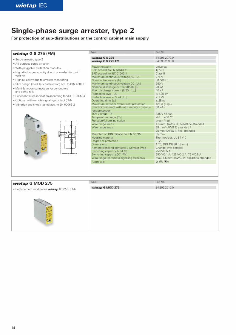
Single-phase surge arrester, type 2For protection of sub-distributions or the control cabinet main supply
Type Part No.
• Surge arrester, type 2
• Allpurpose surge arrester
• With pluggable protection modules
• High discharge capacity due to powerful zinc oxid varistor
• High reliability due to arrester monitoring
• Slim design (modular construction) acc. to DIN 43880
• Multifunction connection for conductors and comb rails
• Function/failure indication according to VDE 0100534
• Optional with remote signaling contact (FM)
• Vibration and shock tested acc. to EN 600682
Type Part No.
• Replacement module for wietap G S 275 (FM)
Power network universalSPD accord. to EN 6164311 Type 2 SPD accord. to IEC 616431 Class II Maximum continuous voltage AC [UC] 275 V Nominal frequency [fN] 50 / 60 HzMaximum continuous voltage DC [UC] 350 V Nominal discharge current (8/20) [In] 20 kA Max. discharge current (8/20) [Imax] 40 kA Protection level [UP] ≤ 1.25 kV Protection level at 5 kA [UP] ≤ 1 kV Operating time [tA] ≤ 25 ns Maximum network overcurrent protection 125 A gL/gG Shortcircuit proof with max. network overcurrent protection
50 kAeff
TOVvoltage [UT] 335 V / 5 sec. Temperature range [TU] 40 ... +80 °C Function/failure indication green / red Wire range (min.) 1.5 mm2 (AWG 14) solid/finestranded Wire range (max.) 35 mm2 (AWG 2) stranded /
25 mm2 (AWG 4) finestranded Mounted on DIN rail acc. to EN 60715 35 mm Housing material Thermoplast, UL 94 V0Degree of protection IP 20 Dimensions 1 TE, DIN 43880 (18 mm)Remote signaling contacts = Contact Type Changeover contact Switching capacity AC (FM) 250 V/0,5 A Switching capacity DC (FM) 250 V/0.1 A; 125 V/0.2 A; 75 V/0.5 A Wire range for remote signaling terminals max. 1.5 mm2 (AWG 14) solid/finestranded Approvals
AöK
wietap GP C S (FM)
wietap GP C MOD
wietap IEC
wietap GP C S 84.995.2030.0wietap GP C S FM 84.995.2035.0
wietap GP C MOD 84.995.2060.0
15
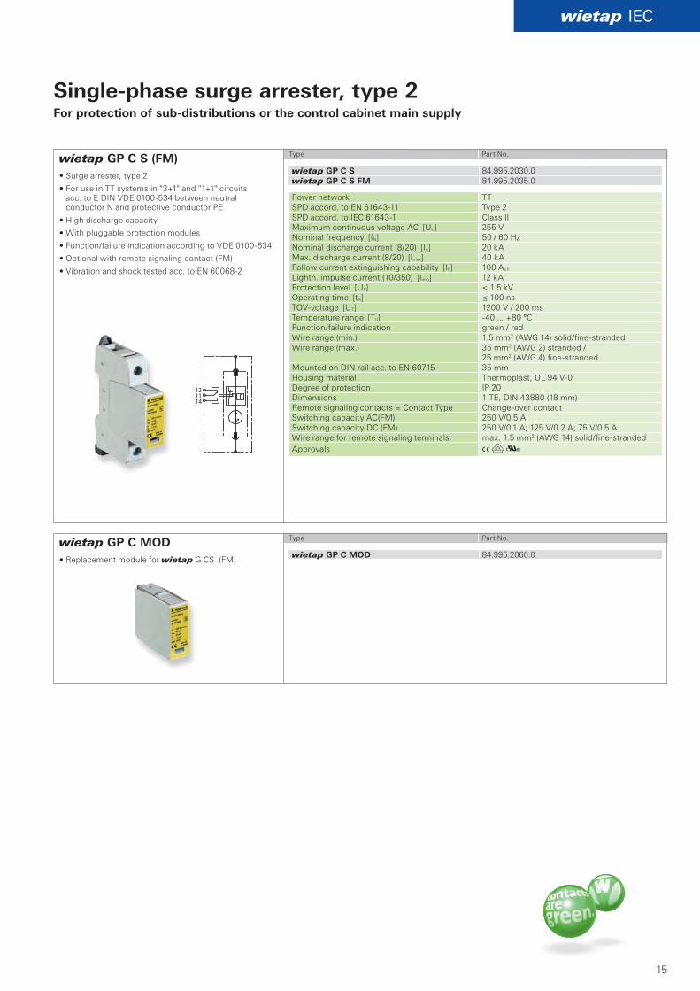
Single-phase surge arrester, type 2For protection of sub-distributions or the control cabinet main supply
Type Part No.
• Surge arrester, type 2
• For use in TT systems in "3+1" and "1+1" circuits acc. to E DIN VDE 0100534 between neutral conductor N and protective conductor PE
• High discharge capacity
• With pluggable protection modules
• Function/failure indication according to VDE 0100534
• Optional with remote signaling contact (FM)
• Vibration and shock tested acc. to EN 600682
• Replacement module for wietap G CS (FM)
Type Part No.
Power network TTSPD accord. to EN 6164311 Type 2 SPD accord. to IEC 616431 Class II Maximum continuous voltage AC [UC] 255 V Nominal frequency [fN] 50 / 60 HzNominal discharge current (8/20) [In] 20 kA Max. discharge current (8/20) [Imax] 40 kA Follow current extinguishing capability [Ifi] 100 Aeff Lightn. impulse current (10/350) [Iimp] 12 kA Protection level [UP] ≤ 1.5 kV Operating time [tA] ≤ 100 ns TOVvoltage [UT] 1200 V / 200 ms Temperature range [TU] 40 ... +80 °C Function/failure indication green / red Wire range (min.) 1.5 mm2 (AWG 14) solid/finestranded Wire range (max.) 35 mm2 (AWG 2) stranded /
25 mm2 (AWG 4) finestranded Mounted on DIN rail acc. to EN 60715 35 mm Housing material Thermoplast, UL 94 V0Degree of protection IP 20 Dimensions 1 TE, DIN 43880 (18 mm)Remote signaling contacts = Contact Type Changeover contact Switching capacity AC(FM) 250 V/0.5 A Switching capacity DC (FM) 250 V/0.1 A; 125 V/0.2 A; 75 V/0.5 A Wire range for remote signaling terminals max. 1.5 mm2 (AWG 14) solid/finestranded Approvals
AöKw
wietap R M 2P 30 FM wietap R M 2P 255 (FM)
wietap R MOD 255
wietap IEC
wietap R M 2P 30 FM 84.995.3206.0wietap R M 2P 255 84.995.3200.0wietap R M 2P 255 FM 84.995.3205.0
wietap R MOD 255 84.995.3010.0
16
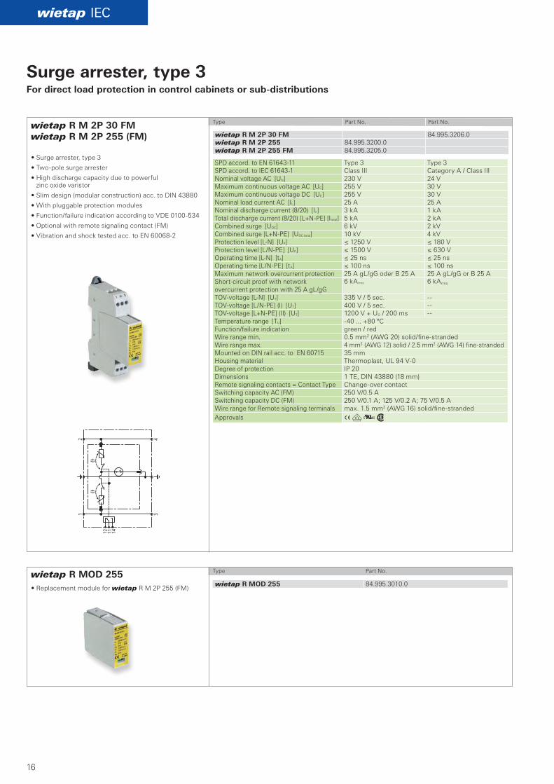
Surge arrester, type 3For direct load protection in control cabinets or sub-distributions
Type Part No. Part No.
• Surge arrester, type 3
• Twopole surge arrester
• High discharge capacity due to powerful zinc oxide varistor
• Slim design (modular construction) acc. to DIN 43880
• With pluggable protection modules
• Function/failure indication according to VDE 0100534
• Optional with remote signaling contact (FM)
• Vibration and shock tested acc. to EN 600682
• Replacement module for wietap R M 2P 255 (FM)
Type Part No.
SPD accord. to EN 6164311 Type 3 Type 3 SPD accord. to IEC 616431 Class III Category A / Class III Nominal voltage AC [UN] 230 V 24 V Maximum continuous voltage AC [UC] 255 V 30 V Maximum continuous voltage DC [UC] 255 V 30 V Nominal load current AC [IL] 25 A 25 A Nominal discharge current (8/20) [In] 3 kA 1 kA Total discharge current (8/20) [L+NPE] [Itotal] 5 kA 2 kA Combined surge [UOC] 6 kV 2 kV Combined surge [L+NPE] [UOC total] 10 kV 4 kV Protection level [LN] [UP] ≤ 1250 V ≤ 180 V Protection level [L/NPE] [UP] ≤ 1500 V ≤ 630 V Operating time [LN] [tA] ≤ 25 ns ≤ 25 ns Operating time [L/NPE] [tA] ≤ 100 ns ≤ 100 ns Maximum network overcurrent protection 25 A gL/gG oder B 25 A 25 A gL/gG or B 25 A Shortcircuit proof with network overcurrent protection with 25 A gL/gG
6 kArms 6 kArms
TOVvoltage [LN] [UT] 335 V / 5 sec. TOVvoltage [L/NPE] (I) [UT] 400 V / 5 sec. TOVvoltage [L+NPE] (II) [UT] 1200 V + UO / 200 ms Temperature range [TU] 40 ... +80 °C Function/failure indication green / red Wire range min. 0.5 mm2 (AWG 20) solid/finestranded Wire range max. 4 mm2 (AWG 12) solid / 2.5 mm2 (AWG 14) finestranded Mounted on DIN rail acc. to EN 60715 35 mm Housing material Thermoplast, UL 94 V0Degree of protection IP 20 Dimensions 1 TE, DIN 43880 (18 mm)Remote signaling contacts = Contact Type Changeover contact Switching capacity AC (FM) 250 V/0.5 A Switching capacity DC (FM) 250 V/0.1 A; 125 V/0.2 A; 75 V/0.5 A Wire range for Remote signaling terminals max. 1.5 mm2 (AWG 16) solid/finestrandedApprovals
AöK
wietap R M 4P 255 (FM)
wietap R M MOD 4P 255
wietap IEC
L1 L1 L2 L2
N N
ϑ
L3 L3
121114
PE PE
ϑϑ
wietap R M 4P 255 84.995.3400.0wietap R M 4P 255 FM 84.995.3405.0
wietap R M MOD 4P 255 84.995.3020.0
17
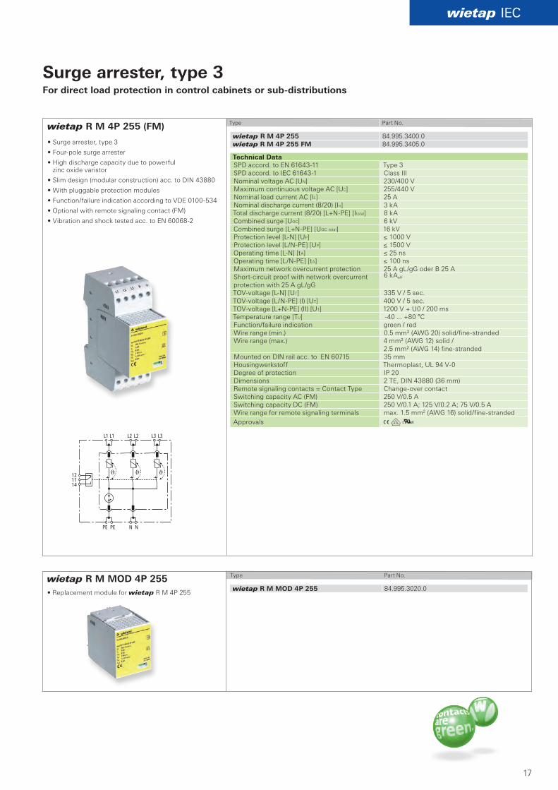
Surge arrester, type 3For direct load protection in control cabinets or sub-distributions
Type Part No.
• Surge arrester, type 3
• Fourpole surge arrester
• High discharge capacity due to powerful zinc oxide varistor
• Slim design (modular construction) acc. to DIN 43880
• With pluggable protection modules
• Function/failure indication according to VDE 0100534
• Optional with remote signaling contact (FM)
• Vibration and shock tested acc. to EN 600682
Technical Data SPD accord. to EN 6164311 Type 3 SPD accord. to IEC 616431 Class III Nominal voltage AC [UN] 230/400 V Maximum continuous voltage AC [UC] 255/440 V Nominal load current AC [IL] 25 A Nominal discharge current (8/20) [In] 3 kA Total discharge current (8/20) [L+NPE] [Itotal] 8 kA Combined surge [UOC] 6 kV Combined surge [L+NPE] [UOC total] 16 kV Protection level [LN] [UP] ≤ 1000 V Protection level [L/NPE] [UP] ≤ 1500 V Operating time [LN] [tA] ≤ 25 ns Operating time [L/NPE] [tA] ≤ 100 ns Maximum network overcurrent protection 25 A gL/gG oder B 25 A Shortcircuit proof with network overcurrent protection with 25 A gL/gG
6 kAeff
TOVvoltage [LN] [UT] 335 V / 5 sec. TOVvoltage [L/NPE] (I) [UT] 400 V / 5 sec. TOVvoltage [L+NPE] (II) [UT] 1200 V + U0 / 200 ms Temperature range [TU] 40 ... +80 °C Function/failure indication green / red Wire range (min.) 0.5 mm² (AWG 20) solid/finestranded Wire range (max.) 4 mm² (AWG 12) solid /
2.5 mm² (AWG 14) finestranded Mounted on DIN rail acc. to EN 60715 35 mmHousingwerkstoff Thermoplast, UL 94 V0Degree of protection IP 20 Dimensions 2 TE, DIN 43880 (36 mm) Remote signaling contacts = Contact Type Changeover contact Switching capacity AC (FM) 250 V/0.5 A Switching capacity DC (FM) 250 V/0.1 A; 125 V/0.2 A; 75 V/0.5 AWire range for remote signaling terminals max. 1.5 mm2 (AWG 16) solid/finestranded Approvals
• Replacement module for wietap R M 4P 255
Type Part No.
18
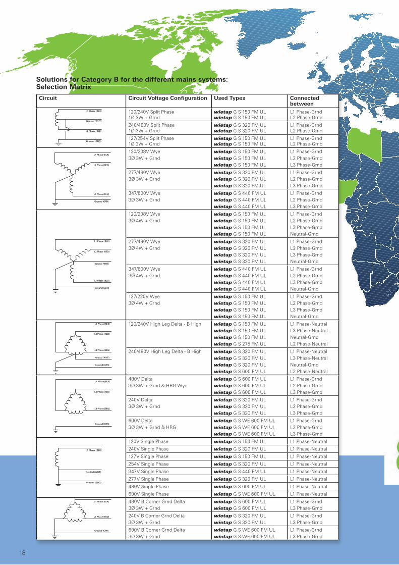
120/240V Split Phase 1Ø 3W + Grnd
wietap G S 150 FM ULwietap G S 150 FM UL
L1 PhaseGrndL2 PhaseGrnd
240/480V Split Phase 1Ø 3W + Grnd
wietap G S 320 FM ULwietap G S 320 FM UL
L1 PhaseGrndL2 PhaseGrnd
127/254V Split Phase 1Ø 3W + Grnd
wietap G S 150 FM ULwietap G S 150 FM UL
L1 PhaseGrndL2 PhaseGrnd
120/208V Wye 3Ø 3W + Grnd
wietap G S 150 FM ULwietap G S 150 FM ULwietap G S 150 FM UL
L1 PhaseGrndL2 PhaseGrndL3 PhaseGrnd
277/480V Wye3Ø 3W + Grnd
wietap G S 320 FM ULwietap G S 320 FM ULwietap G S 320 FM UL
L1 PhaseGrndL2 PhaseGrndL3 PhaseGrnd
347/600V Wye3Ø 3W + Grnd
wietap G S 440 FM ULwietap G S 440 FM ULwietap G S 440 FM UL
L1 PhaseGrndL2 PhaseGrndL3 PhaseGrnd
120/208V Wye 3Ø 4W + Grnd
wietap G S 150 FM ULwietap G S 150 FM ULwietap G S 150 FM ULwietap G S 150 FM UL
L1 PhaseGrndL2 PhaseGrndL3 PhaseGrndNeutralGrnd
277/480V Wye3Ø 4W + Grnd
wietap G S 320 FM ULwietap G S 320 FM ULwietap G S 320 FM ULwietap G S 320 FM UL
L1 PhaseGrndL2 PhaseGrndL3 PhaseGrndNeutralGrnd
347/600V Wye3Ø 4W + Grnd
wietap G S 440 FM ULwietap G S 440 FM ULwietap G S 440 FM ULwietap G S 440 FM UL
L1 PhaseGrndL2 PhaseGrndL3 PhaseGrndNeutralGrnd
127/220V Wye3Ø 4W + Grnd
wietap G S 150 FM ULwietap G S 150 FM ULwietap G S 150 FM ULwietap G S 150 FM UL
L1 PhaseGrndL2 PhaseGrndL3 PhaseGrndNeutralGrnd
120/240V High Leg Delta B High wietap G S 150 FM ULwietap G S 150 FM ULwietap G S 150 FM ULwietap G S 275 FM UL
L1 PhaseNeutralL3 PhaseNeutralNeutralGrndL2 PhaseNeutral
240/480V High Leg Delta B High wietap G S 320 FM ULwietap G S 320 FM ULwietap G S 320 FM ULwietap G S 600 FM UL
L1 PhaseNeutralL3 PhaseNeutralNeutralGrndL2 PhaseNeutral
480V Delta 3Ø 3W + Grnd & HRG Wye
wietap G S 600 FM ULwietap G S 600 FM ULwietap G S 600 FM UL
L1 PhaseGrndL2 PhaseGrndL3 PhaseGrnd
240V Delta3Ø 3W + Grnd
wietap G S 320 FM ULwietap G S 320 FM ULwietap G S 320 FM UL
L1 PhaseGrndL2 PhaseGrndL3 PhaseGrnd
600V Delta3Ø 3W + Grnd & HRG
wietap G S WE 600 FM ULwietap G S WE 600 FM ULwietap G S WE 600 FM UL
L1 PhaseGrndL2 PhaseGrndL3 PhaseGrnd
120V Single Phase wietap G S 150 FM UL L1 PhaseNeutral
240V Single Phase wietap G S 320 FM UL L1 PhaseNeutral
127V Single Phase wietap G S 150 FM UL L1 PhaseNeutral
254V Single Phase wietap G S 320 FM UL L1 PhaseNeutral
347V Single Phase wietap G S 440 FM UL L1 PhaseNeutral
277V Single Phase wietap G S 320 FM UL L1 PhaseNeutral
480V Single Phase wietap G S 600 FM UL L1 PhaseNeutral
600V Single Phase wietap G S WE 600 FM UL L1 PhaseNeutral
480V B Corner Grnd Delta3Ø 3W + Grnd
wietap G S 600 FM ULwietap G S 600 FM UL
L1 PhaseGrndL3 PhaseGrnd
240V B Corner Grnd Delta3Ø 3W + Grnd
wietap G S 320 FM ULwietap G S 320 FM UL
L1 PhaseGrndL3 PhaseGrnd
600V B Corner Grnd Delta3Ø 3W + Grnd
wietap G S WE 600 FM ULwietap G S WE 600 FM UL
L1 PhaseGrndL3 PhaseGrnd
Circuit Circuit Voltage Configuration Used Types Connected between
Solutions for Category B for the different mains systems: Selection Matrix
wietap UL / CSA
19
4 3
2 1
✙
✙
R M 2P 255
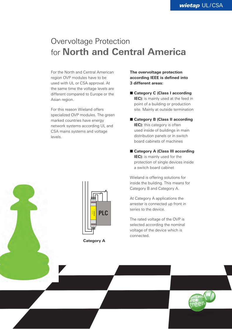
Overvoltage Protection for North and Central America
For the North and Central American region OVP modules have to be used with UL or CSA approval. At the same time the voltage levels are different compared to Europe or the Asian region.
For this reason Wieland offers specialized OVP modules. The green marked countries have energy network systems according UL and CSA mains systems and voltage levels.
The overvoltage protection according IEEE is defined into 3 different areas:
■ Category C (Class I according IEC): is mainly used at the feed in point of a building or production site. Mainly at outside termination
■ Category B (Class II according IEC): this category is often used inside of buildings in main distribution panels or in switch board cabinets of machines
■ Category A (Class III according IEC): is mainly used for the protection of single devices inside a switch board cabinet
Wieland is offering solutions for inside the building. This means for Category B and Category A.
At Category A applications the arrester is connected up front in series to the device.
The rated voltage of the OVP is selected according the nominal voltage of the device which is connected.
Category A
PLC
A Kw
A L Kw
wietap UL / CSA
wietap G S 150 FM ULwietap G S 275 FM UL
wietap G S 320 FM ULwietap G S 385 FM UL
wietap G S 150 FM UL 84.995.2092.1wietap G S 275 FM UL 84.995.2090.1
wietap G S 320 FM UL 84.995.2093.1wietap G S 385 FM UL 84.995.2094.1
121114
121114
20
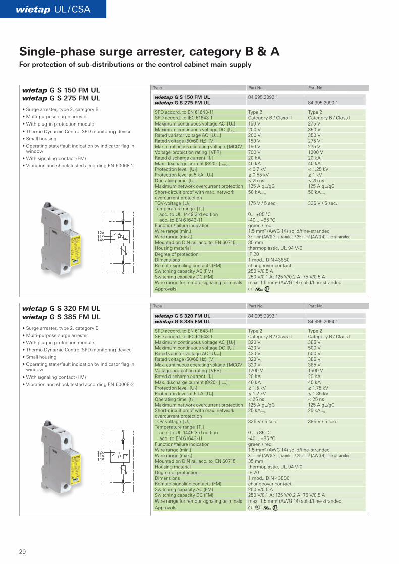
Single-phase surge arrester, category B & AFor protection of sub-distributions or the control cabinet main supply
Type Part No. Part No.
Type Part No. Part No.
• Surge arrester, type 2, category B
• Multipurpose surge arrester
• With plugin protection module
• Thermo Dynamic Control SPD monitoring device
• Small housing
• Operating state/fault indication by indicator flag in window
• With signaling contact (FM)
• Vibration and shock tested according EN 600682
SPD accord. to EN 6164311 Type 2 Type 2 SPD accord. to IEC 616431 Category B / Class II Category B / Class II Maximum continuous voltage AC [UC] 150 V 275 V Maximum continuous voltage DC [UC] 200 V 350 V Rated varistor voltage AC [Umov] 200 V 350 V Rated voltage (50/60 Hz) [V] 150 V 275 V Max. continuous operating voltage [MCOV] 150 V 275 V Voltage protection rating [VPR] 700 V 1000 V Rated discharge current [In] 20 kA 20 kA Max. discharge current (8/20) [Imax] 40 kA 40 kA Protection level [UP] ≤ 0.7 kV ≤ 1.25 kV Protection level at 5 kA [UP] ≤ 0.55 kV ≤ 1 kV Operating time [tA] ≤ 25 ns ≤ 25 ns Maximum network overcurrent protection 125 A gL/gG 125 A gL/gG Shortcircuit proof with max. network overcurrent protection
50 kArms 50 kArms
TOVvoltage [UT] 175 V / 5 sec. 335 V / 5 sec. Temperature range [TU] acc. to UL 1449 3rd edition acc. to EN 6164311
0... +85 °C 40... +85 °C
Function/failure indication green / red Wire range (min.) 1.5 mm2 (AWG 14) solid/finestrandedWire range (max.) 35 mm2 (AWG 2) stranded / 25 mm2 (AWG 4) fine-strandedMounted on DIN rail acc. to EN 60715 35 mm Housing material thermoplastic, UL 94 V0 Degree of protection IP 20 Dimensions 1 mod., DIN 43880 Remote signaling contacts (FM) changeover contact Switching capacity AC (FM) 250 V/0.5 A Switching capacity DC (FM) 250 V/0.1 A; 125 V/0.2 A; 75 V/0.5 AWire range for remote signaling terminals max. 1.5 mm2 (AWG 14) solid/finestrandedApprovals
SPD accord. to EN 6164311 Type 2 Type 2 SPD accord. to IEC 616431 Category B / Class II Category B / Class II Maximum continuous voltage AC [UC] 320 V 385 V Maximum continuous voltage DC [UC] 420 V 500 V Rated varistor voltage AC [Umov] 420 V 500 V Rated voltage (50/60 Hz) [V] 320 V 385 V Max. continuous operating voltage [MCOV] 320 V 385 V Voltage protection rating [VPR] 1200 V 1500 V Rated discharge current [In] 20 kA 20 kA Max. discharge current (8/20) [Imax] 40 kA 40 kA Protection level [UP] ≤ 1.5 kV ≤ 1.75 kV Protection level at 5 kA [UP] ≤ 1.2 kV ≤ 1.35 kV Operating time [tA] ≤ 25 ns ≤ 25 ns Maximum network overcurrent protection 125 A gL/gG 125 A gL/gG Shortcircuit proof with max. network overcurrent protection
25 kArms 25 kArms
TOVvoltage [UT] 335 V / 5 sec. 385 V / 5 sec. Temperature range [TU] acc. to UL 1449 3rd edition acc. to EN 6164311
0... +85 °C 40... +85 °C
Function/failure indication green / red Wire range (min.) 1.5 mm2 (AWG 14) solid/finestrandedWire range (max.) 35 mm2 (AWG 2) stranded / 25 mm2 (AWG 4) fine-strandedMounted on DIN rail acc. to EN 60715 35 mm Housing material thermoplastic, UL 94 V0 Degree of protection IP 20 Dimensions 1 mod., DIN 43880 Remote signaling contacts (FM) changeover contact Switching capacity AC (FM) 250 V/0.5 A Switching capacity DC (FM) 250 V/0.1 A; 125 V/0.2 A; 75 V/0.5 AWire range for remote signaling terminals max. 1.5 mm2 (AWG 14) solid/finestrandedApprovals
A Kw
A Kw
wietap UL / CSA
wietap G S 440 FM ULwietap G S 600 FM UL
wietap G S WE 600 FM UL
wietap G S 440 FM UL 84.995.2095.1wietap G S 600 FM UL 84.995.2096.1
wietap G S WE 600 FM UL 84.995.2097.1
121114
121114
21
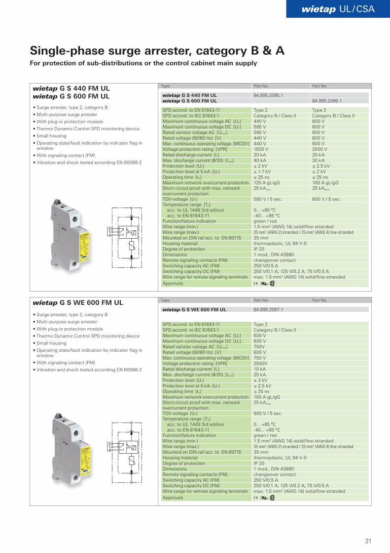
Single-phase surge arrester, category B & AFor protection of sub-distributions or the control cabinet main supply
Type Part No. Part No.
Type Part No. Part No.
• Surge arrester, type 2, category B
• Multipurpose surge arrester
• With plugin protection module
• Thermo Dynamic Control SPD monitoring device
• Small housing
• Operating state/fault indication by indicator flag in window
• With signaling contact (FM)
• Vibration and shock tested according EN 600682
• Surge arrester, type 2, category B
• Multipurpose surge arrester
• With plugin protection module
• Thermo Dynamic Control SPD monitoring device
• Small housing
• Operating state/fault indication by indicator flag in window
• With signaling contact (FM)
• Vibration and shock tested according EN 600682
SPD accord. to EN 6164311 Type 2 Type 2 SPD accord. to IEC 616431 Category B / Class II Category B / Class II Maximum continuous voltage AC [UC] 440 V 600 V Maximum continuous voltage DC [UC] 585 V 600 V Rated varistor voltage AC [Umov] 585 V 600 V Rated voltage (50/60 Hz) [V] 440 V 600 V Max. continuous operating voltage [MCOV] 440 V 600 V Voltage protection rating [VPR] 1500 V 2000 V Rated discharge current [In] 20 kA 20 kAMax. discharge current (8/20) [Imax] 40 kA 30 kA Protection level [UP] ≤ 2 kV ≤ 2.5 kV Protection level at 5 kA [UP] ≤ 1.7 kV ≤ 2 kV Operating time [tA] ≤ 25 ns ≤ 25 ns Maximum network overcurrent protection 125 A gL/gG 100 A gL/gG Shortcircuit proof with max. network overcurrent protection
25 kArms 25 kArms
TOVvoltage [UT] 580 V / 5 sec. 600 V / 5 sec. Temperature range [TU] acc. to UL 1449 3rd edition acc. to EN 6164311
0... +85 °C 40... +85 °C
Function/failure indication green / red Wire range (min.) 1.5 mm2 (AWG 14) solid/finestrandedWire range (max.) 35 mm2 (AWG 2) stranded / 25 mm2 (AWG 4) fine-strandedMounted on DIN rail acc. to EN 60715 35 mm Housing material thermoplastic, UL 94 V0 Degree of protection IP 20 Dimensions 1 mod., DIN 43880 Remote signaling contacts (FM) changeover contact Switching capacity AC (FM) 250 V/0.5 A Switching capacity DC (FM) 250 V/0.1 A; 125 V/0.2 A; 75 V/0.5 AWire range for remote signaling terminals max. 1.5 mm2 (AWG 14) solid/finestranded Approvals
SPD accord. to EN 6164311 Type 2 SPD accord. to IEC 616431 Category B / Class II Maximum continuous voltage AC [UC] 600 V Maximum continuous voltage DC [UC] 600 V Rated varistor voltage AC [Umov] 750VRated voltage (50/60 Hz) [V] 600 V Max. continuous operating voltage [MCOV] 750 V Voltage protection rating [VPR] 2500VRated discharge current [In] 10 kAMax. discharge current (8/20) [Imax] 25 kA Protection level [UP] ≤ 3 kV Protection level at 5 kA [UP] ≤ 2.5 kV Operating time [tA] ≤ 25 ns Maximum network overcurrent protection 100 A gL/gG Shortcircuit proof with max. network overcurrent protection
25 kArms
TOVvoltage [UT] 900 V / 5 sec. Temperature range [TU] acc. to UL 1449 3rd edition acc. to EN 6164311
0... +85 °C 40... +85 °C
Function/failure indication green / red Wire range (min.) 1.5 mm2 (AWG 14) solid/finestrandedWire range (max.) 35 mm2 (AWG 2) stranded / 25 mm2 (AWG 4) fine-strandedMounted on DIN rail acc. to EN 60715 35 mm Housing material thermoplastic, UL 94 V0 Degree of protection IP 20 Dimensions 1 mod., DIN 43880 Remote signaling contacts (FM) changeover contact Switching capacity AC (FM) 250 V/0.5 A Switching capacity DC (FM) 250 V/0.1 A; 125 V/0.2 A; 75 V/0.5 AWire range for remote signaling terminals max. 1.5 mm2 (AWG 14) solid/finestrandedApprovals
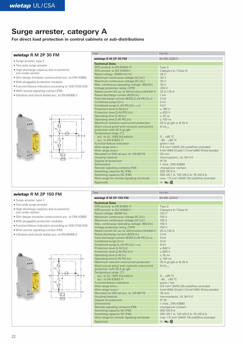
wietap R M 2P 30 FM
wietap R M 2P 150 FM
A Kw
A Kw
wietap UL / CSA
wietap R M 2P 30 FM 84.995.3206.0
wietap R M 2P 150 FM 84.995.3209.0
1 3
2 4
12 11 14
1 3
2 4
12 11 14
22
Surge arrester, category AFor direct load protection in control cabinets or sub-distributions
• Surge arrester, type 3
• Twopole surge arrester
• High discharge capacity due to powerful zinc oxide varistor
• Slim design (modular construction) acc. to DIN 43880
• With pluggable protection modules
• Function/failure indication according to VDE 0100534
• With remote signaling contact (FM)
• Vibration and shock tested acc. to EN 600682
Type Part No.
Type Part No.
Technical Data SPD accord. to EN 6164311 Type 3 SPD accord. to IEC 616431 Category A / Class III Rated voltage (50/60 Hz) [V] 24 VMaximum continuous voltage AC [UC] 30 V Maximum continuous voltage DC [UC] 30 V Max. continuous operating voltage [MCOV] 30 V Voltage protection rating [VPR] 330 V Rated current AC acc. UL 1449 3rd edition | EN 61643-11 20 A | 25 ARated discharge current (8/20) [In] 1 kA Total discharge current (8/20) [L+NPE] [Itotal] 2 kA Combined surge [UOC] 2 kV Combined surge [L+NPE] [UOC total] 4 kV Protection level [LN] [UP] ≤ 180 V Protection level [L/NPE] [UP] ≤ 630 V Operating time [LN] [tA] ≤ 25 ns Operating time [L/NPE] [tA] ≤ 100 ns Maximum network overcurrent protection 25 A gL/gG or B 25 A Shortcircuit proof with network overcurrent protection with 25 A gL/gG
6 kArms
Temperature range [TU] acc. to UL 1449 3rd edition acc. to EN 6164311
0... +85 °C 40... +85 °C
Function/failure indication green / red Wire range (min.) 0.5 mm² (AWG 20) solid/finestrandedWire range (max.) 4 mm² (AWG 12) solid / 2.5 mm² (AWG 14) fine-strandedMounted on DIN rail acc. to EN 60715 35 mmHousing material thermoplastic, UL 94 V0 Degree of protection IP 20 Dimensions 1 mod., DIN 43880 Remote signaling contacts (FM) changeover contact Switching capacity AC (FM) 250 V/0.5 A Switching capacity DC (FM) 250 V/0.1 A; 125 V/0.2 A; 75 V/0.5 A Wire range for remote signaling terminals max. 1.5 mm2 (AWG 16) solid/finestrandedApprovals
Technical Data SPD accord. to EN 6164311 Type 3 SPD accord. to IEC 616431 Category A / Class III Rated voltage (50/60 Hz) 120 VMaximum continuous voltage AC [UC] 150 V Maximum continuous voltage DC [UC] 150 V Max. continuous operating voltage [MCOV] 150 V Voltage protection rating [VPR] 700 V Rated current AC acc. UL 1449 3rd edition | EN 61643-11 20 A | 25 ARated discharge current (8/20) [In] 2 kA Total discharge current (8/20) [L+NPE] [Itotal] 4 kA Combined surge [UOC] 4 kV Combined surge [L+NPE] [UOC total] 8 kV Protection level [LN] [UP] ≤ 640 V Protection level [L/NPE] [UP] ≤ 800 V Operating time [LN] [tA] ≤ 25 ns Operating time [L/NPE] [tA] ≤ 100 ns Maximum network overcurrent protection 25 A gL/gG or B 25 A Shortcircuit proof with network overcurrent protection with 25 A gL/gG
6 kArms
Temperature range [TU] acc. to UL 1449 3rd edition acc. to EN 6164311
0... +85 °C 40... +85 °C
Function/failure indication green / red Wire range (min.) 0.5 mm² (AWG 20) solid/finestrandedWire range (max.) 4 mm² (AWG 12) solid / 2.5 mm² (AWG 14) fine-stranded Mounted on DIN rail acc. to EN 60715 35 mmHousing material thermoplastic, UL 94 V0 Degree of protection IP 20 Dimensions 1 mod., DIN 43880 Remote signaling contacts (FM) changeover contact Switching capacity AC (FM) 250 V/0.5 A Switching capacity DC (FM) 250 V/0.1 A; 125 V/0.2 A; 75 V/0.5 AWire range for remote signaling terminals max. 1.5 mm2 (AWG 14) solid/finestrandedApprovals
AöKw
AöKw
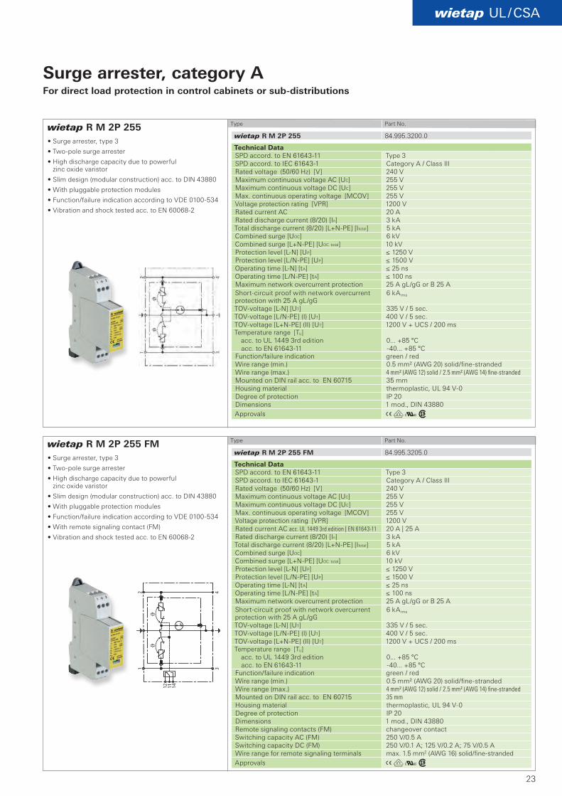
wietap R M 2P 255
wietap R M 2P 255 FM
wietap UL / CSA
wietap R M 2P 255 84.995.3200.0
wietap R M 2P 255 FM 84.995.3205.0
23
Type Part No.
Type Part No.
Technical Data SPD accord. to EN 6164311 Type 3 SPD accord. to IEC 616431 Category A / Class III Rated voltage (50/60 Hz) [V] 240 VMaximum continuous voltage AC [UC] 255 V Maximum continuous voltage DC [UC] 255 V Max. continuous operating voltage [MCOV] 255 V Voltage protection rating [VPR] 1200 V Rated current AC 20 ARated discharge current (8/20) [In] 3 kA Total discharge current (8/20) [L+NPE] [Itotal] 5 kA Combined surge [UOC] 6 kV Combined surge [L+NPE] [UOC total] 10 kV Protection level [LN] [UP] ≤ 1250 V Protection level [L/NPE] [UP] ≤ 1500 V Operating time [LN] [tA] ≤ 25 ns Operating time [L/NPE] [tA] ≤ 100 ns Maximum network overcurrent protection 25 A gL/gG or B 25 A Shortcircuit proof with network overcurrent protection with 25 A gL/gG
6 kArms
TOVvoltage [LN] [UT] 335 V / 5 sec. TOVvoltage [L/NPE] (I) [UT] 400 V / 5 sec. TOVvoltage [L+NPE] (II) [UT] 1200 V + UCS / 200 ms Temperature range [TU] acc. to UL 1449 3rd edition acc. to EN 6164311
0... +85 °C 40... +85 °C
Function/failure indication green / red Wire range (min.) 0.5 mm² (AWG 20) solid/finestranded Wire range (max.) 4 mm² (AWG 12) solid / 2.5 mm² (AWG 14) fine-stranded Mounted on DIN rail acc. to EN 60715 35 mmHousing material thermoplastic, UL 94 V0 Degree of protection IP 20 Dimensions 1 mod., DIN 43880 Approvals
Technical Data SPD accord. to EN 6164311 Type 3 SPD accord. to IEC 616431 Category A / Class III Rated voltage (50/60 Hz) [V] 240 VMaximum continuous voltage AC [UC] 255 V Maximum continuous voltage DC [UC] 255 V Max. continuous operating voltage [MCOV] 255 V Voltage protection rating [VPR] 1200 V Rated current AC acc. UL 1449 3rd edition | EN 61643-11 20 A | 25 ARated discharge current (8/20) [In] 3 kA Total discharge current (8/20) [L+NPE] [Itotal] 5 kA Combined surge [UOC] 6 kV Combined surge [L+NPE] [UOC total] 10 kV Protection level [LN] [UP] ≤ 1250 V Protection level [L/NPE] [UP] ≤ 1500 V Operating time [LN] [tA] ≤ 25 ns Operating time [L/NPE] [tA] ≤ 100 ns Maximum network overcurrent protection 25 A gL/gG or B 25 A Shortcircuit proof with network overcurrent protection with 25 A gL/gG
6 kArms
TOVvoltage [LN] [UT] 335 V / 5 sec. TOVvoltage [L/NPE] (I) [UT] 400 V / 5 sec. TOVvoltage [L+NPE] (II) [UT] 1200 V + UCS / 200 ms Temperature range [TU] acc. to UL 1449 3rd edition acc. to EN 6164311
0... +85 °C 40... +85 °C
Function/failure indication green / red Wire range (min.) 0.5 mm² (AWG 20) solid/finestranded Wire range (max.) 4 mm² (AWG 12) solid / 2.5 mm² (AWG 14) fine-stranded Mounted on DIN rail acc. to EN 60715 35 mmHousing material thermoplastic, UL 94 V0 Degree of protection IP 20 Dimensions 1 mod., DIN 43880 Remote signaling contacts (FM) changeover contact Switching capacity AC (FM) 250 V/0.5 A Switching capacity DC (FM) 250 V/0.1 A; 125 V/0.2 A; 75 V/0.5 AWire range for remote signaling terminals max. 1.5 mm2 (AWG 16) solid/finestrandedApprovals
Surge arrester, category AFor direct load protection in control cabinets or sub-distributions
• Surge arrester, type 3
• Twopole surge arrester
• High discharge capacity due to powerful zinc oxide varistor
• Slim design (modular construction) acc. to DIN 43880
• With pluggable protection modules
• Function/failure indication according to VDE 0100534
• Vibration and shock tested acc. to EN 600682
• Surge arrester, type 3
• Twopole surge arrester
• High discharge capacity due to powerful zinc oxide varistor
• Slim design (modular construction) acc. to DIN 43880
• With pluggable protection modules
• Function/failure indication according to VDE 0100534
• With remote signaling contact (FM)
• Vibration and shock tested acc. to EN 600682

24
25
wietap DC Solar
DC
Photovoltaic systems, abbreviated as PV systems, are a considerable investment that must be protected from failure and damage. As these systems are installed outdoors, they are exposed to the danger of overvoltage from lightning strikes.
Overvoltage protection in the DC circuit with central inverters
The generator circuit (the PV modules) produces a direct current. Connecting the PV modules and arrays in series allows voltages of 1000 V to be reached. This combination with the fact that the generator circuit can continue to supply energy after overvoltage requires sophisticated technology for the overvoltage arrester.
Overvoltage protection for
Photovoltaic systems
DC overvoltage protection:
The PV/DC overvoltage arresters are specially designed for use in PV systems.
Both the housing technology and the connections are designed for the requirements of a PV systems high voltages and conductor crosssections. With a width of only 36 or 48 mm, the units are easily installed inside distribution panels, requiring the minimum of space.
■ High discharge capacity due to powerful zinc-oxide varistor
■ No fire hazard caused by permanent electric arc due to combined disconnect and short-circuit facility. Overload indicated in display window
■ Signaling contacts for remote monitoring in all remote signaling types
AC overvoltage protection:
On the AC side of the inverters overvoltage protection must also be installed. The arresters listed here are the most commonly used versions.
Suitable units can be found inside the chapters wietap IEC and wietap UL/CSA.
A Kw
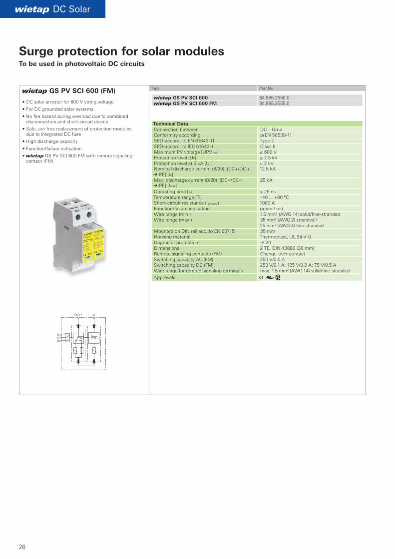
wietap GS PV SCI 600 (FM)
wietap DC Solar
wietap GS PV SCI 600 84.995.2550.0wietap GS PV SCI 600 FM 84.995.2555.0
26
Surge protection for solar modulesTo be used in photovoltaic DC circuits
• DC solar arrester for 600 V string voltage
• For DC grounded solar systems
• No fire hazard during overload due to combined disconnection and shortcircuit device
• Safe, arcfree replacement of protection modules due to integrated DC fuse
• High discharge capacity
• Function/failure indication
• wietap GS PV SCI 600 FM with remote signaling contact (FM)
Type Part No.
Technical Data Connection between DC – GrndConformity according prEN 5053911SPDaccord. to EN 6164311 Type 2 SPDaccord. to IEC 616431 Class II Maximum PV voltage [UPVmax] ≤ 600 V Protection level [UP] ≤ 2.5 kV Protection level at 5 kA [UP] ≤ 2 kV Nominal discharge current (8/20) [(DC+/DC) PE] [In]
12.5 kA
Max. discharge current (8/20) [(DC+/DC) PE] [Imax]
25 kA
Operating time [tA] ≤ 25 ns Temperature range [TU] 40 ... +80 °C Shortcircuit resistance (ISCWPV) 1000 A Function/failure indication green / red Wire range (min.) 1.5 mm² (AWG 14) solid/finestrandedWire range (max.) 35 mm² (AWG 2) stranded /
25 mm² (AWG 4) finestrandedMounted on DIN rail acc. to EN 60715 35 mmHousing material Thermoplast, UL 94 V0Degree of protection IP 20 Dimensions 2 TE, DIN 43880 (36 mm) Remote signaling contacts (FM) Changeover contact Switching capacity AC (FM) 250 V/0.5 A Switching capacity DC (FM) 250 V/0.1 A; 125 V/0.2 A; 75 V/0.5 AWire range for remote signaling terminals max. 1.5 mm² (AWG 14) solid/finestrandedApprovals
A Kw
wietap GM YPV SCI 600 (FM)
wietap DC Solar
wietap G MOD PV SCI 300 84.995.2053.0
wietap G MOD 275 84.995.2010.0
wietap GM YPV SCI 600 84.995.2511.0wietap GM YPV SCI 600 FM 84.995.2516.0
84.995.2053.084.995.2010.0
27
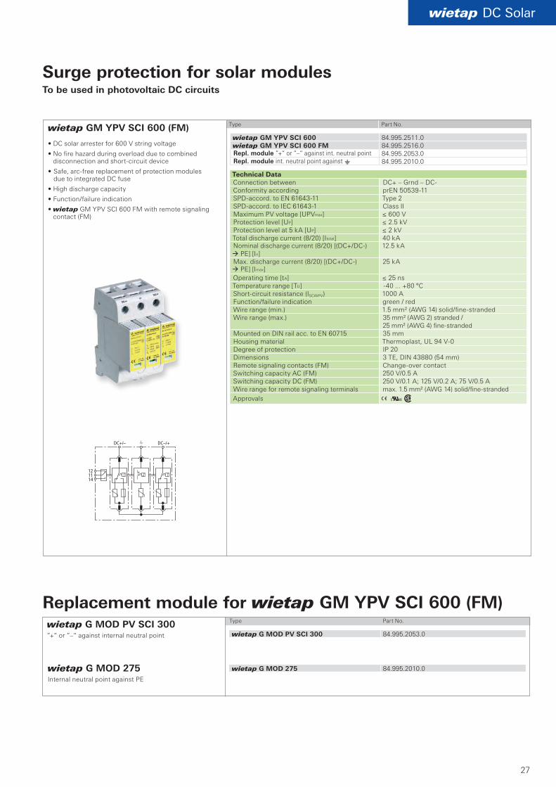
Surge protection for solar modulesTo be used in photovoltaic DC circuits
Type Part No.
Technical Data Connection between DC+ – Grnd – DCConformity according prEN 5053911SPDaccord. to EN 6164311 Type 2 SPDaccord. to IEC 616431 Class II Maximum PV voltage [UPVmax] ≤ 600 V Protection level [UP] ≤ 2.5 kV Protection level at 5 kA [UP] ≤ 2 kV Total discharge current (8/20) [Itotal] 40 kA Nominal discharge current (8/20) [(DC+/DC) PE] [In]
12.5 kA
Max. discharge current (8/20) [(DC+/DC) PE] [Imax]
25 kA
Operating time [tA] ≤ 25 ns Temperature range [TU] 40 ... +80 °C Shortcircuit resistance (ISCWPV) 1000 A Function/failure indication green / red Wire range (min.) 1.5 mm² (AWG 14) solid/finestrandedWire range (max.) 35 mm² (AWG 2) stranded /
25 mm² (AWG 4) finestrandedMounted on DIN rail acc. to EN 60715 35 mmHousing material Thermoplast, UL 94 V0Degree of protection IP 20 Dimensions 3 TE, DIN 43880 (54 mm) Remote signaling contacts (FM) Changeover contact Switching capacity AC (FM) 250 V/0.5 A Switching capacity DC (FM) 250 V/0.1 A; 125 V/0.2 A; 75 V/0.5 AWire range for remote signaling terminals max. 1.5 mm² (AWG 14) solid/finestrandedApprovals
Type Part No.
wietap G MOD 275Internal neutral point against PE
Replacement module for wietap GM YPV SCI 600 (FM)
Repl. module ”+“ or ”–“ against int. neutral pointRepl. module int. neutral point against e
wietap G MOD PV SCI 300”+“ or ”–“ against internal neutral point
• DC solar arrester for 600 V string voltage
• No fire hazard during overload due to combined disconnection and shortcircuit device
• Safe, arcfree replacement of protection modules due to integrated DC fuse
• High discharge capacity
• Function/failure indication
• wietap GM YPV SCI 600 FM with remote signaling contact (FM)
A Kw
wietap GM YPV SCI 1000 (FM)
wietap DC Solar
wietap G MOD PV SCI 500 84.995.2051.0
wietap G MOD 440 84.995.2015.0
wietap GM YPV SCI 1000 84.995.2510.0wietap GM YPV SCI 1000 FM 84.995.2515.0
84.995.2051.084.995.2015.0
28
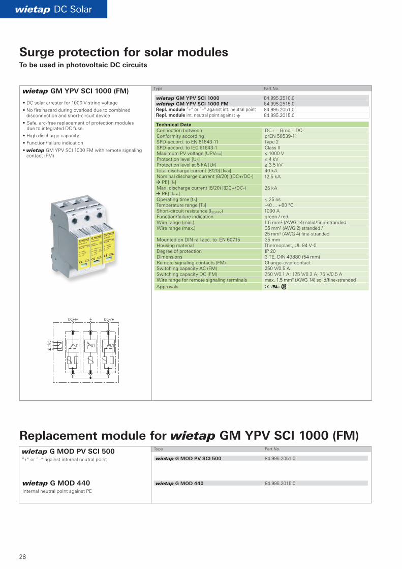
Surge protection for solar modulesTo be used in photovoltaic DC circuits
• DC solar arrester for 1000 V string voltage
• No fire hazard during overload due to combined disconnection and shortcircuit device
• Safe, arcfree replacement of protection modules due to integrated DC fuse
• High discharge capacity
• Function/failure indication
• wietap GM YPV SCI 1000 FM with remote signaling contact (FM)
Type Part No.
Technical Data Connection between DC+ – Grnd – DCConformity according prEN 5053911SPDaccord. to EN 6164311 Type 2 SPDaccord. to IEC 616431 Class II Maximum PV voltage [UPVmax] ≤ 1000 V Protection level [UP] ≤ 4 kV Protection level at 5 kA [UP] ≤ 3.5 kV Total discharge current (8/20) [Itotal] 40 kA Nominal discharge current (8/20) [(DC+/DC) PE] [In]
12.5 kA
Max. discharge current (8/20) [(DC+/DC) PE] [Imax]
25 kA
Operating time [tA] ≤ 25 ns Temperature range [TU] 40 ... +80 °C Shortcircuit resistance (ISCWPV) 1000 A Function/failure indication green / red Wire range (min.) 1.5 mm² (AWG 14) solid/finestranded Wire range (max.) 35 mm² (AWG 2) stranded /
25 mm² (AWG 4) finestranded Mounted on DIN rail acc. to EN 60715 35 mmHousing material Thermoplast, UL 94 V0Degree of protection IP 20 Dimensions 3 TE, DIN 43880 (54 mm) Remote signaling contacts (FM) Changeover contact Switching capacity AC (FM) 250 V/0.5 A Switching capacity DC (FM) 250 V/0.1 A; 125 V/0.2 A; 75 V/0.5 AWire range for remote signaling terminals max. 1.5 mm² (AWG 14) solid/finestranded Approvals
Type Part No.
wietap G MOD 440Internal neutral point against PE
Replacement module for wietap GM YPV SCI 1000 (FM)
Repl. module ”+“ or ”–“ against int. neutral pointRepl. module int. neutral point against e
wietap G MOD PV SCI 500”+“ or ”–“ against internal neutral point
wietap DC Solar
DC
gesi
s®S
OLA
R
Lieferprogramm0064.0 C 05/10
gesis® SOLARElektrische Installations- technik für PhotovoltaikKatalog
Unternehmenszentrale:Wieland Electric GmbHBrennerstraße 10 – 14D-96052 BambergVertriebs- und Marketing Center:Wieland Electric GmbHBenzstraße 9D-96052 Bamberg
Telefon +49-951 93 24-0Telefax +49-951 93 24-198www.wieland-electric.comwww.gesis.cominfo@wieland-electric.com
Industrietechnik Lösungen für den Schaltschrank • Reihenklemmen – Schraub-, Federkraft- oder IDC-Anschlusstechnik
– Leiterquerschnitte bis 240 mm2 – zahlreiche Sonderfunktionen – Softwarelösungen mit Schnittstellen zu CAE-Systemen
• Safety – Sicherheits-Sensorik – Sicherheitsschaltgeräte – modulare Sicherheitssysteme mit Feldbusanbindung
• SPS und Feldbuskomponenten – Standardanwendungen in IP 20 – erhöhte Umweltbedingungen mit Bahn- u. Schiffszulassung
• Interface – Koppelrelais, Halbleiterschalter – Mess- und Überwachungsrelais – Zeit- und Schaltrelais – analoge Bausteine – Übergabebausteine – Stromversorgungen – Überspannungsschutz Lösungen für Feld-Applikationen
• Dezentrale Automatisierungstechnik – Energieverteilung – Feldbusanschaltungen und Motorstarter
• Steckverbinder für industrielle Anwendungen
– Rechteck- und Rundsteckverbinder – Gehäuse aus Aluminium oder Kunststoff – Schutzart bis IP 68 – Strombelastbarkeit bis 100 A
– Steckverbinder für explosionsgefährdete Bereiche
– modulare, applikationsspezifische Technik Leiterplattenklemmen und -steckverbinder – Schraub- oder Federkraftanschlusstechnik – Rastermaße 3,5 mm bis 10,16 mm – Reflow- oder SchwallbadlötprozessGebäude- und Installationstechnik • Gebäudeinstallationssysteme
– Netz-Steckverbinder IP 20/IP 65 ... IP 68 – Bus-Steckverbinder – Kombinations-Steckverbinder
– Niedervolt-Steckverbinder – Energieverteilsystem mit Flachleitungen – Verteiler-Systeme – Bussysteme in KNX-, LON- und Funk-Technologie
– Installationsreihenklemmen – Überspannungsschutz
29
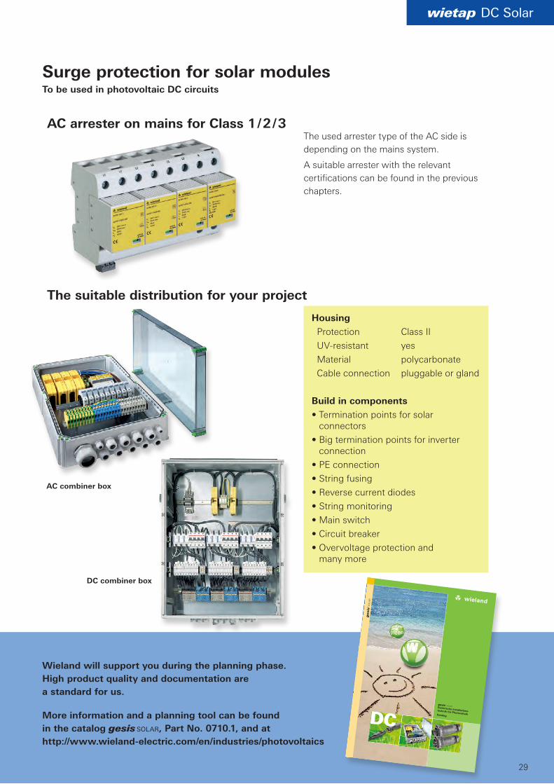
Surge protection for solar modulesTo be used in photovoltaic DC circuits
AC arrester on mains for Class 1 / 2 / 3
The suitable distribution for your project
The used arrester type of the AC side is depending on the mains system.
A suitable arrester with the relevant certifications can be found in the previous chapters.
AC combiner box
DC combiner box
Wieland will support you during the planning phase. High product quality and documentation are a standard for us.
More information and a planning tool can be found in the catalog gesis solar, Part No. 0710.1, and at http://www.wieland-electric.com/en/industries/photovoltaics
Housing Protection Class II UVresistant yes Material polycarbonate Cable connection pluggable or gland
Build in components• Termination points for solar
connectors• Big termination points for inverter
connection• PE connection• String fusing• Reverse current diodes• String monitoring• Main switch• Circuit breaker• Overvoltage protection and
many more

Support
30
Hotline • adviceAdditional information
General information and news:www.wieland-electric.com
Visit our eCAT at http://eshop.wieland-electric.com
Technical support
Automation technology:
Phone: +49 951 9324- . . .
• Safety technology safety -999 e-mail: [email protected]
• interface: -995 Power supply, industrial Ethernet switches, timer relays, measuring and monitoring relays, coupling relays, analog modules, remote I/O, surge protection, passive interfaces, remote power distribution podis®
• DIN rail terminal blocks fasis, selos -991 Industrial multipole connectors revos PCB terminals and connectors wiecon, appliance terminals, european terminal strips, housings for electronic components
Fax: +49 951 9326-991 e-mail: [email protected]
Technical Support
Building services engineering:
Phone: +49 951 9324- . . .
• System connectors for building installation -996 gesis con, gesis ran, gesis electronic
• DIN rail terminal blocks fasis bit, selos bit -991
Fax: +49 951 9326996 e-mail: [email protected]
Sales service:
• To contact our sales department regarding availability, delivery schedules, and pricing please call
Phone: +49 951 9324-990
Technical Support
Photovoltaics/solar technology:
Phone: +49 951 9324- . . .
• Photovoltaics gesis solar -972
Fax: +49 951 9326977 e-mail: [email protected]

contacts are green
31Subject to technical modifications! gesis®, podis®, samos® are registered trademarks of Wieland Electric GmbH
Our subsidiaries... and the addresses of our representations worldwide are available at:
www.wieland-electric.com
CANADAWieland Electric Inc.North American Headquarters2889 Brighton RoadOakville, Ontario L6H 6C9Phone +1 905 8298414 Fax +1 905 8298413 www.wielandelectric.ca
SPAINWieland Electric S.L.C/ Maria Auxiliadora 2 bajosE08017 BarcelonaPhone +34 93 2523820Fax +34 93 2523825ventas@wielandelectric.com
GREAT BRITAINWieland Electric Ltd.Riverside Business Centre, Walnut Tree CloseGBGuildford /Surrey GU1 4UGPhone +44 1483 531213Fax +44 1483 505029sales.uk@wielandelectric.com
CHINAWieland Electric TradingUnit 2703 International Soho City889 Renmin Rd., Huang Pu DistrictPRC Shanghai 200010Phone +86 21 63555833Fax +86 21 63550090infoshanghai@wielandelectric.com
ITALYWieland Electric S.r.l.Via Edison, 209I20019 Settimo MilanesePhone +39 02 48916357Fax +39 02 48 920685info.italy@wielandelectric.com
USAWieland Electric Inc.North American Headquarters2889 Brighton RoadOakville, Ontario L6H 6C9Phone +1 905 8298414 Fax +1 905 8298413 www.wielandinc.com
FRANCEWieland Electric SARL.Le Céramê Hall 647, avenue des GenottesCS 4831395803 CergyPontoise CedexPhone +33 1 30320707Fax +33 1 30320714infos.adv@wielandelectric.com
DENMARKWieland Electric A/SVallørækken 26DK4600 KøgePhone +45 70 266635Fax +45 70 266637sales.denmark@wieland electric.com
Informational material for ordering and for downloading from our websites
POLAND Wieland Electric Sp. Zo.o.Św. Antoniego 862-080 SwadzimPhone +48 61 2225400 Fax +48 61 [email protected]
BELGIUMATEM – Wieland Electric NVBedrijvenpark De Veert 4B2830 WillebroekPhone +32 3 8661800Fax +32 3 8661828info.belgium@wielandelectric.com

Headquarters:Wieland Electric GmbHBrennerstraße 10 – 1496052 Bamberg, Germany
Sales and Marketing Center:Wieland Electric GmbHBenzstraße 996052 Bamberg, Germany
Phone +49 951 9324-0Fax +49 951 [email protected]
Technical Support: Phone +49 (9 51) 93 24-995 Fax +49 (9 51) 93 26-991 [email protected]
0820.1 C 07/13
Industrial technology Solutions for the control cabinet • DIN rail terminal blocks – Screw, tension spring or push-in connection technology – Wire cross sections up to 240 mm2 – Numerous special functions – Software solutions interfacing to CAE systems • Safety – Safe signal acquisition – Safety switching devices – Modular safety modules – Compact safety controllers – Application consulting and training • Network engineering and fieldbus systems – Remote maintenance via VPN industrial router and VPN service portal – Industrial Ethernet switches – PLC and I/O systems, standard and
increased environmental conditions • Interface – Power supply units – Overvoltage protection – Coupling relays, semiconductor switches – Timer relays, measuring and monitoring relays – Analog coupling and converter modules – Passive interfaces Solutions for field applications • Decentralized installation and automation technology – Electrical installation for wind tower – Fieldbus interfaces and motor starters • Connectors for industrial applications – Rectangular and round connectors – Aluminum or plastic housings – Degree of protection up to IP 68 – Current-carrying capacity up to 100 A – Connectors for hazardous areas – Modular, application-specific technology PC board terminals and connectors – Screw or spring clamp connection technology – Spacings: 3.5 mm to 10.16 mm – Reflow or wave soldering process
Building and installation technology • Building installation systems – Main power supply connectors IP 20/IP 65 ... IP 68 – Bus connectors – Low-voltage connectors – Power distribution system with flat cables – Distribution systems – Bus systems in KNX, LON and wireless technology – DIN rail terminal blocks for electrical installations – Overvoltage protection