Embed Size (px)
Citation preview
1
Widex USB LinkUser instrUctions
2
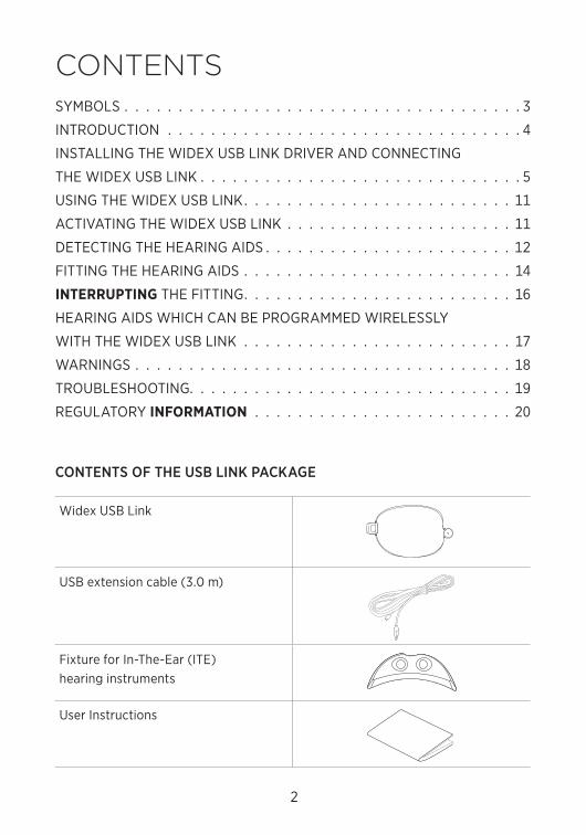
ContentS
CONTENTS OF THE USB LINK PACKAGE
Widex USB Link
USB extension cable (3.0 m)
Fixture for In-The-Ear (ITE) hearing instruments
User Instructions
SymBoLS . . . . . . . . . . . . . . . . . . . . . . . . . . . . . . . . . . . . . 3
InTrodUcTIon . . . . . . . . . . . . . . . . . . . . . . . . . . . . . . . . . 4
InSTALLInG THE WIdEX USB LInK drIVEr And connEcTInG
THE WIdEX USB LInK . . . . . . . . . . . . . . . . . . . . . . . . . . . . . . 5
USInG THE WIdEX USB LInK. . . . . . . . . . . . . . . . . . . . . . . . . 11
AcTIVATInG THE WIdEX USB LInK . . . . . . . . . . . . . . . . . . . . . 11
dETEcTInG THE HEArInG AIdS . . . . . . . . . . . . . . . . . . . . . . . 12
FITTInG THE HEArInG AIdS . . . . . . . . . . . . . . . . . . . . . . . . . 14
InterruptIng THE FITTInG. . . . . . . . . . . . . . . . . . . . . . . . . 16
HEArInG AIdS WHIcH cAn BE proGrAmmEd WIrELESSLy
WITH THE WIdEX USB LInK . . . . . . . . . . . . . . . . . . . . . . . . . 17
WArnInGS . . . . . . . . . . . . . . . . . . . . . . . . . . . . . . . . . . . 18
TroUBLESHooTInG. . . . . . . . . . . . . . . . . . . . . . . . . . . . . . 19
rEGULATory InFOrMAtIOn . . . . . . . . . . . . . . . . . . . . . . . . 20
3
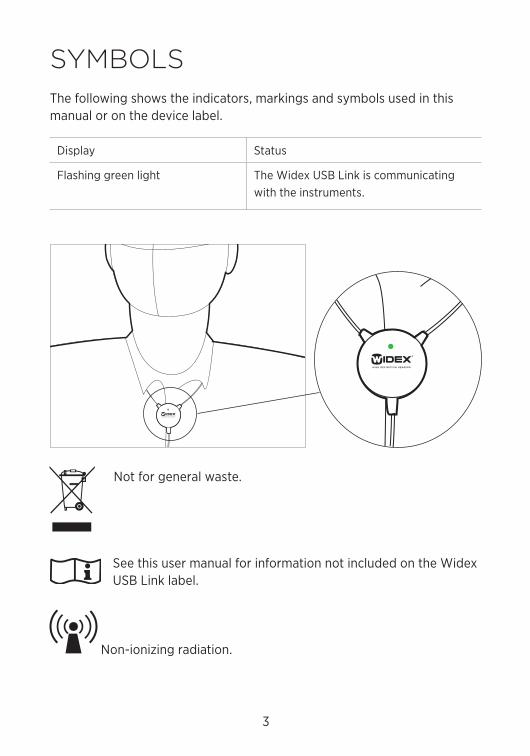
SymBoLSThe following shows the indicators, markings and symbols used in this manual or on the device label.
display Status
Flashing green light The Widex USB Link is communicating with the instruments.
not for general waste.
See this user manual for information not included on the Widex USB Link label.
non-ionizing radiation.
4
introdUCtionThe Widex USB Link makes it possible to fit hearing aids using wireless technology, without the use of cables connected to the hearing aids. The Widex USB Link allows direct connection to the fitting computer, and sup-ports the wireless fitting offered by Widex.
5
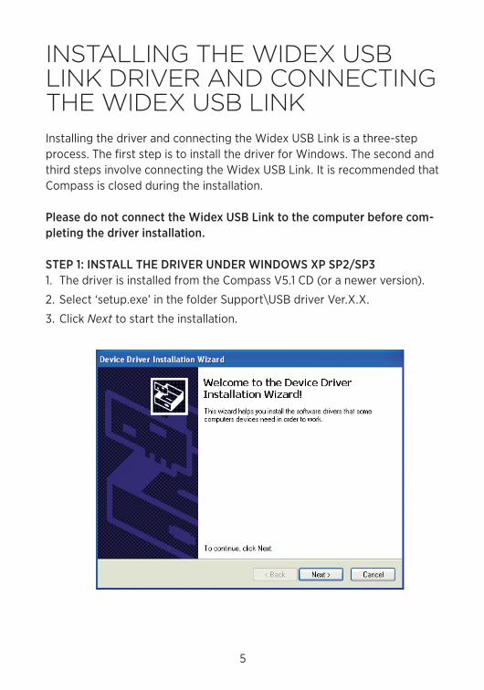
inStALLinG tHe Widex USB Link driVer And ConneCtinG tHe Widex USB LinkInstalling the driver and connecting the Widex USB Link is a three-step process. The first step is to install the driver for Windows. The second and third steps involve connecting the Widex USB Link. It is recommended that compass is closed during the installation.
Please do not connect the Widex USB Link to the computer before com-pleting the driver installation.
STEP 1: INSTALL THE DRIVER UNDER WINDOWS XP SP2/SP31. The driver is installed from the compass V5.1 cd (or a newer version).
2. Select ‘setup.exe’ in the folder Support\USB driver Ver.X.X.
3. click Next to start the installation.

6
4. When the installation is completed, select Finish.
7
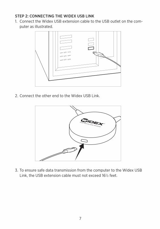
STEP 2: CONNECTING THE WIDEX USB LINK1. connect the Widex USB extension cable to the USB outlet on the com-
puter as illustrated.
2. connect the other end to the Widex USB Link.
3. To ensure safe data transmission from the computer to the Widex USB Link, the USB extension cable must not exceed 16½ feet.
8
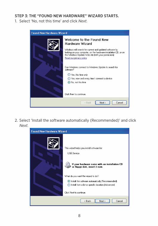
STEP 3: THE “FOUND NEW HARDWARE” WIzARD STARTS.1. Select ‘no, not this time’ and click Next.
2. Select ’Install the software automatically (recommended)’ and click Next.
9
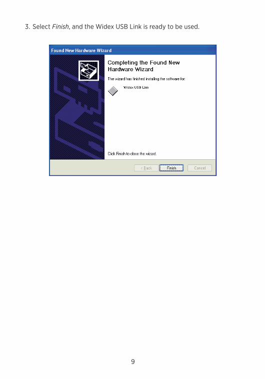
3. Select Finish, and the Widex USB Link is ready to be used.
10
Windows Vista SP2 When you install under a Windows Vista system, the steps are the same as earlier described (see pages 5-6), but when you connect the Widex USB Link, Windows Vista automatically installs it.
you must use Windows Vista Sp2 Edition or later.
Windows 7 When you install under a Windows 7 system, the steps are the same as earlier described (see pages 5-6), but when you connect the Widex USB Link, you have to open the Windows device manager and activate ‘Scan for new Hardware’.
11
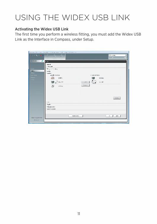
USinG tHe Widex USB LinkActivating the Widex USB LinkThe first time you perform a wireless fitting, you must add the Widex USB Link as the Interface in compass, under Setup.
12
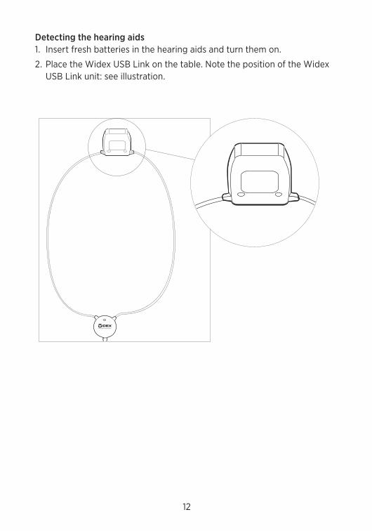
Detecting the hearing aids1. Insert fresh batteries in the hearing aids and turn them on.
2. place the Widex USB Link on the table. note the position of the Widex USB Link unit: see illustration.
13
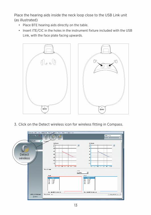
place the hearing aids inside the neck loop close to the USB Link unit (as illustrated)
• place BTE hearing aids directly on the table.
• Insert ITE/cIc in the holes in the instrument fixture included with the USB Link, with the face plate facing upwards.
3. click on the detect wireless icon for wireless fitting in compass.
14
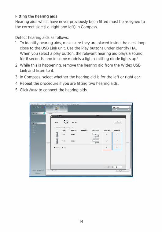
Fitting the hearing aidsHearing aids which have never previously been fitted must be assigned to the correct side (i.e. right and left) in compass.
detect hearing aids as follows:1. To identify hearing aids, make sure they are placed inside the neck loop
close to the USB Link unit. Use the play buttons under Identify HA. When you select a play button, the relevant hearing aid plays a sound for 6 seconds, and in some models a light-emitting diode lights up.1
2. While this is happening, remove the hearing aid from the Widex USB Link and listen to it.
3. In compass, select whether the hearing aid is for the left or right ear.
4. repeat the procedure if you are fitting two hearing aids.
5. click Next to connect the hearing aids.
15
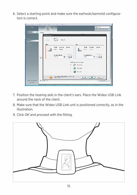
6. Select a starting point and make sure the earhook/earmold configura-tion is correct.
7. position the hearing aids in the client’s ears. place the Widex USB Link around the neck of the client.
8. make sure that the Widex USB Link unit is positioned correctly, as in the illustration.
9. click OK and proceed with the fitting.
16
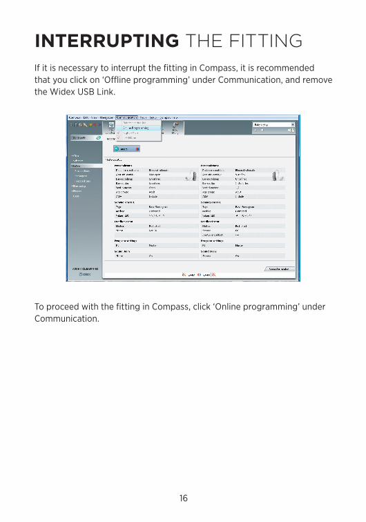
interrUpting tHe fittinGIf it is necessary to interrupt the fitting in compass, it is recommended that you click on ‘offline programming’ under communication, and remove the Widex USB Link.
To proceed with the fitting in compass, click ‘online programming’ under communication.
17
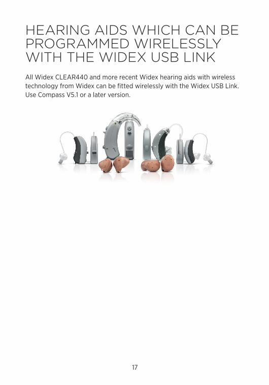
HeArinG AidS WHiCH CAn Be proGrAmmed WireLeSSLy WitH tHe Widex USB LinkAll Widex cLEAr440 and more recent Widex hearing aids with wireless technology from Widex can be fitted wirelessly with the Widex USB Link. Use compass V5.1 or a later version.
18
WArninGS1. clean the Widex USB Link with a soft cloth. never wash your Widex USB
Link with water, cleaning solutions or other liquids.
2. never try to open or repair the Widex USB Link yourself. (This should only be done by authorized personnel.)
3. do not disconnect the Widex USB Link during use.
4. do not use defective units together with the hearing aids.
5. Although your Widex USB Link has been designed to comply with the most stringent international electromagnetic compatibility standards, the possibility cannot be excluded that it may cause interference with other equipment, such as medical devices.
6. do not use the Widex USB Link on aircraft.
7. do not use the Widex USB Link in mines or other areas with explosive gases.
8. do not carry the Widex USB Link with you during X-rays, scans or radia-tion treatments and never place the USB Link in a microwave oven.
19
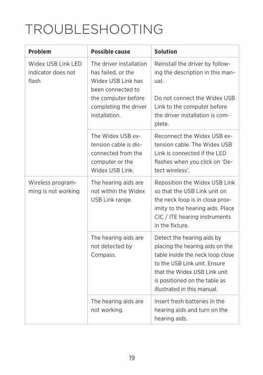
troUBLeSHootinGproblem possible cause Solution
Widex USB Link LEd indicator does not flash
The driver installation has failed, or the Widex USB Link has been connected to the computer before completing the driver installation.
reinstall the driver by follow-ing the description in this man-ual.
do not connect the Widex USB Link to the computer before the driver installation is com-plete.
The Widex USB ex-tension cable is dis-connected from the computer or the Widex USB Link.
reconnect the Widex USB ex-tension cable. The Widex USB Link is connected if the LEd flashes when you click on ‘de-tect wireless’.
Wireless program-ming is not working
The hearing aids are not within the Widex USB Link range.
reposition the Widex USB Link so that the USB Link unit on the neck loop is in close prox-imity to the hearing aids. place cIc / ITE hearing instruments in the fixture.
The hearing aids are not detected by compass.
detect the hearing aids by placing the hearing aids on the table inside the neck loop close to the USB Link unit. Ensure that the Widex USB Link unit is positioned on the table as illustrated in this manual.
The hearing aids are not working.
Insert fresh batteries in the hearing aids and turn on the hearing aids.
20
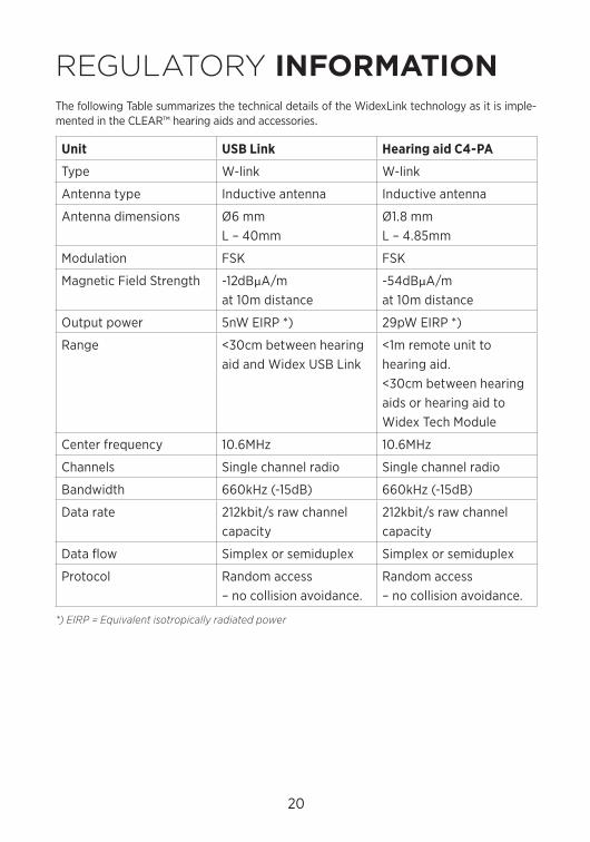
reGULAtory inForMAtion The following Table summarizes the technical details of the WidexLink technology as it is imple-mented in the cLEAr™ hearing aids and accessories.
unit uSB Link Hearing aid C4-pA
Type W-link W-link
Antenna type Inductive antenna Inductive antenna
Antenna dimensions Ø6 mmL – 40mm
Ø1.8 mmL – 4.85mm
modulation FSK FSK
magnetic Field Strength -12dBμA/m at 10m distance
-54dBμA/m at 10m distance
output power 5nW EIrp *) 29pW EIrp *)
range <30cm between hearing aid and Widex USB Link
<1m remote unit to hearing aid.<30cm between hearing aids or hearing aid to Widex Tech module
center frequency 10.6mHz 10.6mHz
channels Single channel radio Single channel radio
Bandwidth 660kHz (-15dB) 660kHz (-15dB)
data rate 212kbit/s raw channel capacity
212kbit/s raw channel capacity
data flow Simplex or semiduplex Simplex or semiduplex
protocol random access – no collision avoidance.
random access – no collision avoidance.
*) EIRP = Equivalent isotropically radiated power
21
The USB Link contains a radio transmitter / receiver with the following Radio transmitter parameters:
• Frequency (range): 10.6 mHz (10.2 – 11.0 mHz)• Bandwidth (-15dB): 660 kHz• channel: Single channel radio• modulation: FSK• radiated output power: 32 nW / -45 dBm• magnetic field strength: -12 dBlA/m @ 10 m• duty cycle: 50 % (averaged over 1 hour of operation)• Simplex or semi duplex capability
The radio receiver in the USB Link programming module is using the same frequency and band-width as the transmitter.
Cables and transducers: The USB Link is using a standard USB extension cable.
22
Quality of Service for Wireless Technology in the WidexLink SystemWidexLink wireless technology enables communication between two partners of a binaural pair of cLEAr hearing aids and with their matched external devices. The requirements for the quality of service (QoS) vary among the various components and their intended user scenarios.
For programming, these requirements include a BEr (Bit Error rate) better than 10-3, at a bitrate of 212 kbits/s, a semi-duplex transmission with a required acknowledge, a transmission latency in each direction (2x) and a receive-to-transmit mode (rX to TX) time. The data are saved in the hearing aid even when transmission is interrupted.
Wireless Security MeasuresSecurity of the wireless signals is assured through device system design that includes:
• Individual mAc address for each unit which is checked during each transmission.• A built-in pairing table which specifies valid and legitimate pairing among units• A proprietary Widex communication protocol which checks the package numbers
during each transmission.• A cyclic redundancy check (crc) to check data validity and correct errors,• A secure Bluetooth connection that is pass-key protected• Authorized usage of programming software with single log-in
23
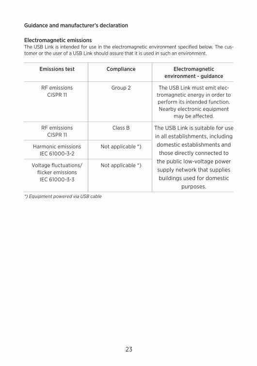
Guidance and manufacturer’s declaration
Electromagnetic emissions The USB Link is intended for use in the electromagnetic environment specified below. The cus-tomer or the user of a USB Link should assure that it is used in such an environment.
Emissions test Compliance Electromagnetic environment - guidance
rF emissionscISpr 11
Group 2 The USB Link must emit elec-tromagnetic energy in order to perform its intended function. nearby electronic equipment
may be affected.
rF emissionscISpr 11
class B The USB Link is suitable for use in all establishments, including domestic establishments and those directly connected to
the public low-voltage power supply network that supplies buildings used for domestic
purposes.
Harmonic emissionsIEc 61000-3-2
not applicable *)
Voltage fluctuations/ flicker emissionsIEc 61000-3-3
not applicable *)
*) Equipment powered via USB cable
24
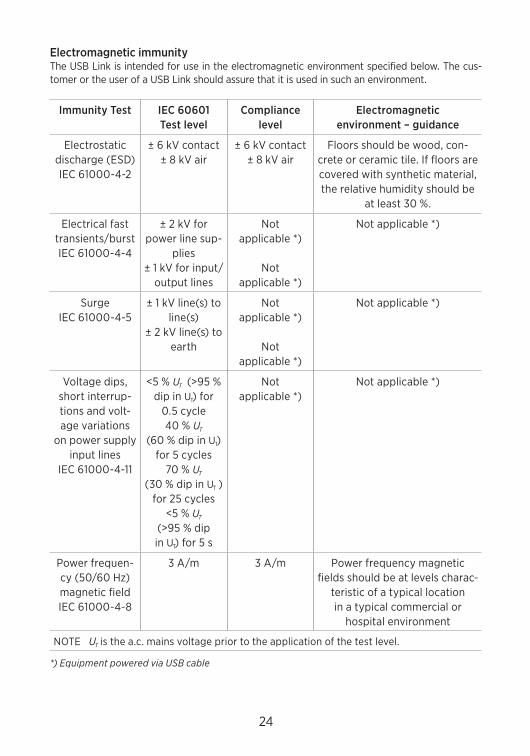
Electromagnetic immunityThe USB Link is intended for use in the electromagnetic environment specified below. The cus-tomer or the user of a USB Link should assure that it is used in such an environment.
Immunity Test IEC 60601Test level
Compliance level
Electromagnetic environment – guidance
Electrostatic discharge (ESd)IEc 61000-4-2
± 6 kV contact± 8 kV air
± 6 kV contact± 8 kV air
Floors should be wood, con-crete or ceramic tile. If floors are covered with synthetic material, the relative humidity should be
at least 30 %.
Electrical fast transients/burstIEc 61000-4-4
± 2 kV for power line sup-
plies± 1 kV for input/
output lines
not applicable *)
not applicable *)
not applicable *)
SurgeIEc 61000-4-5
± 1 kV line(s) to line(s)
± 2 kV line(s) to earth
not applicable *)
not applicable *)
not applicable *)
Voltage dips, short interrup-tions and volt-age variations
on power supply input lines
IEc 61000-4-11
<5 % UT (>95 % dip in UT) for
0.5 cycle40 % UT
(60 % dip in UT) for 5 cycles
70 % UT (30 % dip in UT )
for 25 cycles<5 % UT
(>95 % dip in UT) for 5 s
not applicable *)
not applicable *)
power frequen-cy (50/60 Hz) magnetic fieldIEc 61000-4-8
3 A/m 3 A/m power frequency magnetic fields should be at levels charac-
teristic of a typical location in a typical commercial or
hospital environment
noTE UT is the a.c. mains voltage prior to the application of the test level.
*) Equipment powered via USB cable
25
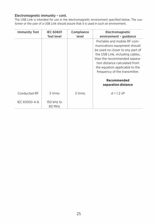
Electromagnetic immunity – cont.The USB Link is intended for use in the electromagnetic environment specified below. The cus-tomer or the user of a USB Link should assure that it is used in such an environment.
Immunity Test IEC 60601Test level
Compliance level
Electromagnetic environment – guidance
conducted rF
IEc 61000-4-6
3 Vrms
150 kHz to 80 mHz
3 Vrms
portable and mobile rF com-munications equipment should be used no closer to any part of the USB Link, including cables, than the recommended separa-
tion distance calculated from the equation applicable to the frequency of the transmitter.
recommended separation distance
d = 1.2 √P
26
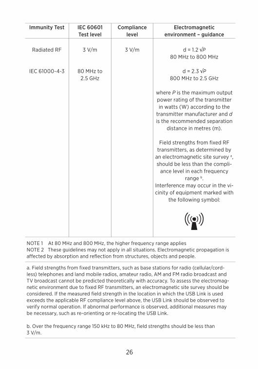
Immunity Test IEC 60601Test level
Compliance level
Electromagnetic environment – guidance
radiated rF
IEc 61000-4-3
3 V/m
80 mHz to 2.5 GHz
3 V/m d = 1.2 √P 80 mHz to 800 mHz
d = 2.3 √P 800 mHz to 2.5 GHz
where P is the maximum output power rating of the transmitter in watts (W) according to the
transmitter manufacturer and d is the recommended separation
distance in metres (m).
Field strengths from fixed rF transmitters, as determined by
an electromagnetic site survey a, should be less than the compli-
ance level in each frequency range b.
Interference may occur in the vi-cinity of equipment marked with
the following symbol:
noTE 1 At 80 mHz and 800 mHz, the higher frequency range appliesnoTE 2 These guidelines may not apply in all situations. Electromagnetic propagation is affected by absorption and reflection from structures, objects and people.
a. Field strengths from fixed transmitters, such as base stations for radio (cellular/cord-less) telephones and land mobile radios, amateur radio, Am and Fm radio broadcast and TV broadcast cannot be predicted theoretically with accuracy. To assess the electromag-netic environment due to fixed rF transmitters, an electromagnetic site survey should be considered. If the measured field strength in the location in which the USB Link is used exceeds the applicable rF compliance level above, the USB Link should be observed to verify normal operation. If abnormal performance is observed, additional measures may be necessary, such as re-orienting or re-locating the USB Link.
b. over the frequency range 150 kHz to 80 mHz, field strengths should be less than 3 V/m.
27
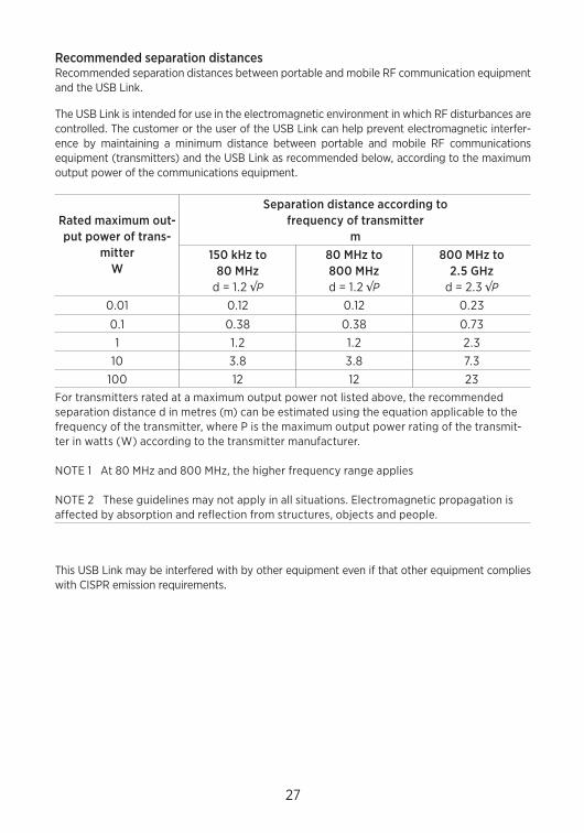
Recommended separation distancesrecommended separation distances between portable and mobile rF communication equipment and the USB Link.
The USB Link is intended for use in the electromagnetic environment in which rF disturbances are controlled. The customer or the user of the USB Link can help prevent electromagnetic interfer-ence by maintaining a minimum distance between portable and mobile rF communications equipment (transmitters) and the USB Link as recommended below, according to the maximum output power of the communications equipment.
Rated maximum out-put power of trans-
mitterW
Separation distance according to frequency of transmitter
m150 kHz to
80 MHzd = 1.2 √P
80 MHz to 800 MHzd = 1.2 √P
800 MHz to 2.5 GHz
d = 2.3 √P 0.01 0.12 0.12 0.23
0.1 0.38 0.38 0.731 1.2 1.2 2.3
10 3.8 3.8 7.3100 12 12 23
For transmitters rated at a maximum output power not listed above, the recommended separation distance d in metres (m) can be estimated using the equation applicable to the frequency of the transmitter, where p is the maximum output power rating of the transmit-ter in watts (W) according to the transmitter manufacturer.
noTE 1 At 80 mHz and 800 mHz, the higher frequency range applies
noTE 2 These guidelines may not apply in all situations. Electromagnetic propagation is affected by absorption and reflection from structures, objects and people.
This USB Link may be interfered with by other equipment even if that other equipment complies with cISpr emission requirements.
28
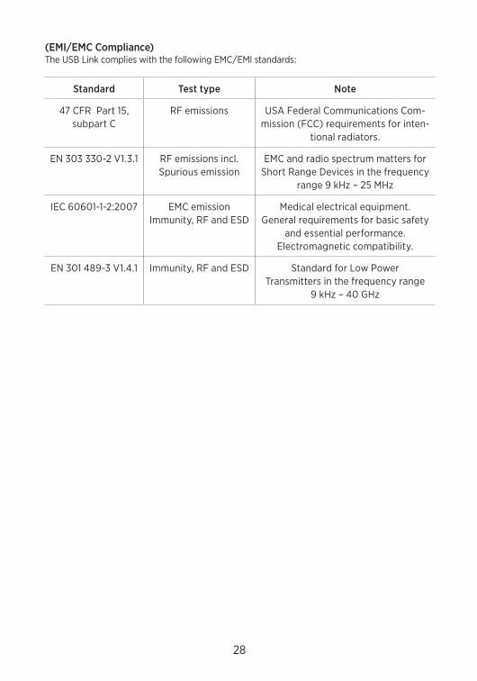
(EMI/EMC Compliance) The USB Link complies with the following Emc/EmI standards:
Standard Test type Note
47 cFr part 15, subpart c
rF emissions USA Federal communications com-mission (Fcc) requirements for inten-
tional radiators.
En 303 330-2 V1.3.1 rF emissions incl. Spurious emission
Emc and radio spectrum matters for Short range devices in the frequency
range 9 kHz – 25 mHz
IEc 60601-1-2:2007 Emc emissionImmunity, rF and ESd
medical electrical equipment.General requirements for basic safety
and essential performance. Electromagnetic compatibility.
En 301 489-3 V1.4.1 Immunity, rF and ESd Standard for Low power Transmitters in the frequency range
9 kHz – 40 GHz
29
Warning to Hearing Aid DispensersA hearing aid dispenser should advise a prospective hearing aid user to consult promptly with a licensed physician (preferably an ear specialist) before dispensing a hearing aid if the hearing aid dispenser determines through inquiry, actual observation, or review of any other available infor-mation concerning the prospective user, that the prospective user has any of the following condi-tions:
(i) Visible congenital or traumatic deformity of the ear.
(ii) History of active drainage from the ear within the previous 90 days.
(iii) History of sudden or rapidly progressive hearing loss within the previous 90 days.
(iv) Acute or chronic dizziness.
(v) Unilateral hearing loss of sudden or recent onset within the previous 90 days.
(vi) Audiometric air-bone gap equal to or greater than 15 decibels at 500 hertz (Hz), 1,000 Hz, and 2,000 Hz.
(vii) Visible evidence of significant cerumen accumulation or a foreign body in the ear canal.
(viii) pain or discomfort in the ear.
Special care should be exercised in selecting and fitting a hearing aid whose maximum sound pressure level exceeds 132 decibels because there may be risk of impairing the remaining hearing of the hearing aid user. (This provision is required only for those hearing aids with a maximum sound pressure capability greater than 132 decibels (dB).)
30
Important notice for prospective hearing aid users Good health practice requires that a person with a hearing loss have a medical evaluation by a li-censed physician (preferably a physician who specializes in diseases of the ear) before purchasing a hearing aid. Licensed physicians who specialize in diseases of the ear are often referred to as otolaryngologists, otologists, or otorhinolaryngologists. The purpose of medical evaluation is to assure that all medically treatable conditions that may affect hearing are identified and treated before the hearing aid is purchased.
Following the medical evaluation, the physician will give you a written statement that states that your hearing loss has been medically evaluated and that you may be considered a candidate for a hearing aid. The physician will refer you to an audiologist or a hearing aid dispenser, as appropri-ate, for a hearing aid evaluation.
The audiologist or hearing aid dispenser will conduct a hearing aid evaluation to assess your ability to hear with and without a hearing aid. The hearing aid evaluation will enable the audiolo-gist or dispenser to select and fit a hearing aid to your individual needs.
If you have reservations about your ability to adapt to amplification, you should inquire about the availability of a trial-rental or purchase-option program. many hearing aid dispensers now offer programs that permit you to wear a hearing aid for a period of time for a nominal fee after which you may decide if you want to purchase the hearing aid.
Federal law restricts the sale of hearing aids to those individuals who have obtained a medical evaluation from a licensed physician. Federal law permits a fully informed adult to sign a waiver statement declining the medical evaluation for religious or personal beliefs that preclude consul-tation with a physician. The exercise of such a waiver is not in your best health interest and its use is strongly discouraged.
Children with hearing loss In addition to seeing a physician for a medical evaluation, a child with a hearing loss should be directed to an audiologist for evaluation and rehabilitation since hearing loss may cause problems in language development and the educational and social growth of a child. An audiologist is qualified by training and experience to assist in the evaluation and rehabilitation of a child with a hearing loss.
31
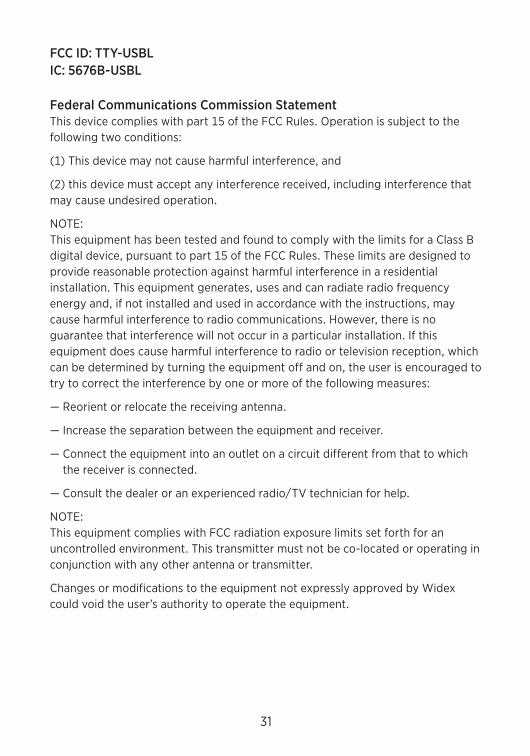
FCC ID: TTY-USBLIC: 5676B-USBL
Federal Communications Commission Statement This device complies with part 15 of the Fcc rules. operation is subject to the following two conditions:
(1) This device may not cause harmful interference, and
(2) this device must accept any interference received, including interference that may cause undesired operation.
noTE: This equipment has been tested and found to comply with the limits for a class B digital device, pursuant to part 15 of the Fcc rules. These limits are designed to provide reasonable protection against harmful interference in a residential installation. This equipment generates, uses and can radiate radio frequency energy and, if not installed and used in accordance with the instructions, may cause harmful interference to radio communications. However, there is no guarantee that interference will not occur in a particular installation. If this equipment does cause harmful interference to radio or television reception, which can be determined by turning the equipment off and on, the user is encouraged to try to correct the interference by one or more of the following measures:
— reorient or relocate the receiving antenna.
— Increase the separation between the equipment and receiver.
— connect the equipment into an outlet on a circuit different from that to which the receiver is connected.
— consult the dealer or an experienced radio/TV technician for help.
noTE: This equipment complies with Fcc radiation exposure limits set forth for an uncontrolled environment. This transmitter must not be co-located or operating in conjunction with any other antenna or transmitter.
changes or modifications to the equipment not expressly approved by Widex could void the user’s authority to operate the equipment.
32
Industry Canada Statement / Déclaration d’industrie CanadaUnder Industry canada regulations, this radio transmitter may only operate using an antenna of a type and maximum (or lesser) gain approved for the transmitter by Industry canada.
To reduce potential radio interference to other users, the antenna type and its gain should be so chosen that the equivalent isotropically radiated power (e.i.r.p.) is not more than that necessary for successful communication.
This device complies with Industry canada licence-exempt rSS standard(s). operation is subject to the following two conditions:
(1) this device may not cause interference, and
(2) this device must accept any interference, including interference that may cause undesired operation of the device.
conformément à la réglementation d’Industrie canada, le présent émetteur radio peut fonctionner avec une antenne d’un type et d’un gain maximal (ou inférieur) approuvé pour l’émetteur par Industrie canada.
dans le but de réduire les risques de brouillage radioélectrique à l’intention des autres utilisateurs, il faut choisir le type d’antenne et son gain de sorte que la puissance isotrope rayonnée équivalente (p.i.r.e.) ne dépasse pas l’intensité nécessaire à l’établissement d’une communication satisfaisante.
Le présent appareil est conforme aux cnr d’Industrie canada applicables aux appareils radio exempts de licence. L’exploitation est autorisée aux deux conditions suivantes :
(1) l’appareil ne doit pas produire de brouillage, et
(2) l’utilisateur de l’appareil doit accepter tout brouillage radioélectrique subi, même si le brouillage est susceptible d’en compromettre le fonctionnement.
33
Hearing aids, accessories and batteries should not be disposed of with normal household waste. please consult your national Widex distributor for advice on how to dispose of these items.
Hereby, Widex A/S declares that this USB Link is in compliance with the essential requirements and other relevant provisions of directive 1999/5/Ec.
A copy of the declaration of conformity can be found at: http://www.widex.com

34

35

36
CIB
199
/04
11 /
20
11-0
4
9 5
02
1810
04
1 #
01
Nymoellevej 6, DK-3540 LyngeDenmark www.widexpro.com