Embed Size (px)
Citation preview
Wideband, Efficient Optical SerrodyneFrequency Shifting with a Phase
Modulator and a NonlinearTransmission Line
Rachel Houtz1,2, Cheong Chan1 and Holger Muller1
1Department of Physics, 261, Birge Hall, University of California at BerkeleyBerkeley, CA, 94720 USA
Abstract: We report shifting of the frequency of an 850 nm laser withan instantaneous bandwidth of (350-1650) MHz and an efficiency between35% (minimum) to 80% (best at frequencies around 600 and 1500 MHz)by phase modulation with a sawtooth waveform (“serrodyne frequencyshifting”). We use a fiber-coupled traveling wave electro-optical modulatordriven by a nonlinear transmission line.
© 2009 Optical Society of America
OCIS codes: (060.5060) Phase modulation; (060.5625) Radio frequency photonics; (130.0250)Optoelectronics; (130.3730) Lithium niobate.
References and links1. J. L. Hall and T. W. Hansch, “External dye-laser frequency stabilizer,” Opt. Lett. 9, 502-504 (1984).2. C. Laskoskie, H. Hung, T. El-Wailly, and C. L. Chang, “Ti-LiNbO waveguide serrodyne modulator with ultrahigh
sideband suppression for fiber optic gyroscopes,” J. Lightwave Technol. 4, 600606 (1989).3. E. Voges and K. Petermann, Optische Kommunikationstechnik (Springer, Berlin, 2002).4. N. Fujiwara et al., “140-nm Quasi-Continuous Fast Sweep Using SSG-DBR Lasers,” IEEE Photon. Technol.
Lett. 20, 1015 (2008).5. P. C. D. Hobbs, Building Electro-optical Systems (Wiley, New York, 2000).6. E. A. Donley, T. P. Heavner, F. Levi, M. O. Tataw, and S. R. Jefferts, “Double-pass acousto-optic modulator
system,” Rev. Sci. Instrum. 76, 063112 (2005).7. L. M. Johnson and C. H. Cox, “Serrodyne optical frequency translation with high sideband suppression,” J.
Lightwave Technol. 6, 109112 (1988).8. K. K. Wong and R. M. De La Rue, “Electro-optic-waveguide Frequency Translator in LiNbO3 Fabricated by
Proton Exchange,” Opt. Lett. 7, 546-548 (1982).9. I. Y. Poberezhskiy, B. Bortnik, J. Chou, B. Jalali, and H. R. Fetterman, “Serrodyne Frequency Translation of
Continuous Optical Signals Using Ultrawide-band Electrical Sawtooth Waveform,” IEEE J. Quantum Electron.41, 1533-1539 (2005).
10. Mathieu Laroche, Clia Bartolacci, Guillaume Lesueur, Herve Gilles, and Sylvain Girard, “Serrodyne opticalfrequency shifting for heterodyne self-mixing in a distributed-feedback fiber laser,” Opt. Lett. 33, 2746-2748(2008).
11. S. Hisatake and T. Kobayashi, “Electro-optic transparent frequency conversion of a continuous light wave basedon multistage phase modulation,” Opt. Lett. 31, 498-500 (2006).
12. E. Afshari and A. Hajimiri, “A non-linear transmission line for pulse shaping in silicon,” IEEE J. Solid-StateCircuits, 40, 744752 (2005).
13. Bradley N. Bond and Luca Daniel, “A Piecewise-Linear Moment-Matching Approach to Parameterized Model-Order Reduction for Highly Nonlinear Systems,” IEEE Transactions on Computer-Aided Design Of IntegratedCircuits And Systems, 26, 2116 (2007).
14. E. Udd, Fiber Optic Sensors - An Introduction for Engineers and Scientists (John Wiley and Sons, New York,2006).
#116921 - $15.00 USD Received 8 Sep 2009; revised 5 Oct 2009; accepted 5 Oct 2009; published 8 Oct 2009
(C) 2009 OSA 12 October 2009 / Vol. 17, No. 21 / OPTICS EXPRESS 19235
15. D. M. S. Johnson, J. M. Hogan, S. Chiow, M. A. Kasevich, “Broadband Optical Serrodyne Frequency Shifting,”arXiv:0909.1834.
1. Introduction
Shifting the frequency of a laser is important for many applications in, e.g., atomic, molecularand optical physics, optical measurement, laser frequency and phase stabilization [1], opticalgyroscopes [2], coherent optical communication systems [3], or spectroscopy. Tunable laserscan often replace such frequency shifters especially when a large frequency shift is desired[4]. However, this technique may require phase-locking, be costly, and have a slow responsetime. Acousto-optic modulators (AOM) [5] are commercially available for frequencies between∼ 30−2500 MHz, and achieve high efficiency especially for models up to 200 MHz. However,their tuning range is limited to a relatively narrow (±10%) band around the center frequencyof each individual model, even if the deflection angle change is compensated for in a double-pass configuration. A good example for what can be achieved with such double-pass AOMsis described by Donley et al. where the peak efficiency is 75% and the tuning bandwidth is68 MHz full width at half maximum power for light coupled into a single-mode fiber [6]. Onthe other hand, electro-optical phase modulators (EOMs) can be used to transfer power intosidebands that are symmetric around the frequency of the laser. The frequency shift of thesidebands is in principle variable, but the maximum power transferred to any output frequencyis limited to about 33% with sine wave modulation [5].
Optical serrodyne frequency shifting theoretically allows one to achieve a wideband fre-quency shift with high efficiency [7]. The idea is to use an EOM for applying phase modula-tion with a sawtooth waveform. Driving the EOM with a perfect sawtooth waveform in theoryshifts the frequency of the optical signal with complete suppression of undesired sidebands [7]and 100 % efficiency. Previously shifts with electronically generated sawtooth waveforms havebeen reported in the MHz range [2, 7, 8]. A larger shift of up to 1.28 GHz has been reportedwith a generation of the sawtooth waveform that involved a photonic arbitrary waveform gen-erator [9]. However, this not only requires the use of a femtosecond laser, but also limits theagility of the frequency changes, since the sawtooth period depends on the repetition rate ofthe laser pulses. Optical serrodyne frequency shifting has been utilized to achieve heterodyneself-mixing in a distributed-feedback fiber laser for use in a coherent detection system [10].Serrodyne frequency shifters based on multistage phase modulation have been demonstrated[11].
Here, we describe an entirely electronic method of generating the sawtooth waveform, utiliz-ing a nonlinear transmission line (NLTL). It has the benefit of being much simpler and cheaperto set up than the above photonic method while achieving even larger shifts. We report fre-quency shifting of an 850 nm laser by (350-1650) MHz using a fiber-coupled travelling waveelectro-optical modulator driven by a NLTL. We experimentally demonstrate an efficiency of35% (minimum) to 80% (best at select frequencies around 600 and 1500 MHz). Within thesefrequency ranges, the magnitude of the frequency shift can be instantaneously tuned because itis given by an rf sine wave generator.
2. Description
Figure 1 shows the experimental setup. It can be broken down into two main parts: First, theserrodyne shifter, which consists of the electronics and the EOM and second, an interferometerthat we use to characterize the frequency shifting by a beat note measurement.
Our serrodyne shifter consists of the fiber-coupled EOM and the sawtooth generator based onthe NLTL and associated drive electronics. The EOM is a lithium niobate modulator (PM-0K5-10-PFU-PFU-850-UL by EOSpace) with pigtailed polarization-maintaining fibers connected
#116921 - $15.00 USD Received 8 Sep 2009; revised 5 Oct 2009; accepted 5 Oct 2009; published 8 Oct 2009
(C) 2009 OSA 12 October 2009 / Vol. 17, No. 21 / OPTICS EXPRESS 19236
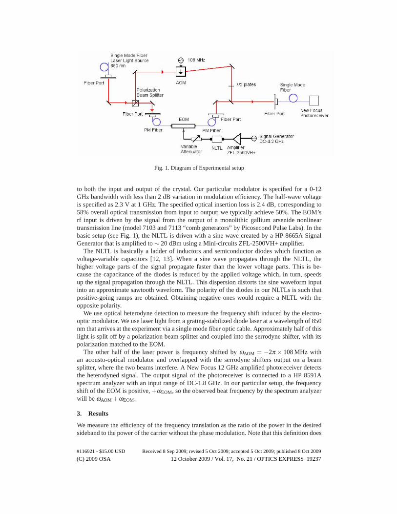
Fig. 1. Diagram of Experimental setup
to both the input and output of the crystal. Our particular modulator is specified for a 0-12GHz bandwidth with less than 2 dB variation in modulation efficiency. The half-wave voltageis specified as 2.3 V at 1 GHz. The specified optical insertion loss is 2.4 dB, corresponding to58% overall optical transmission from input to output; we typically achieve 50%. The EOM’srf input is driven by the signal from the output of a monolithic gallium arsenide nonlineartransmission line (model 7103 and 7113 “comb generators” by Picosecond Pulse Labs). In thebasic setup (see Fig. 1), the NLTL is driven with a sine wave created by a HP 8665A SignalGenerator that is amplified to ∼ 20 dBm using a Mini-circuits ZFL-2500VH+ amplifier.
The NLTL is basically a ladder of inductors and semiconductor diodes which function asvoltage-variable capacitors [12, 13]. When a sine wave propagates through the NLTL, thehigher voltage parts of the signal propagate faster than the lower voltage parts. This is be-cause the capacitance of the diodes is reduced by the applied voltage which, in turn, speedsup the signal propagation through the NLTL. This dispersion distorts the sine waveform inputinto an approximate sawtooth waveform. The polarity of the diodes in our NLTLs is such thatpositive-going ramps are obtained. Obtaining negative ones would require a NLTL with theopposite polarity.
We use optical heterodyne detection to measure the frequency shift induced by the electro-optic modulator. We use laser light from a grating-stabilized diode laser at a wavelength of 850nm that arrives at the experiment via a single mode fiber optic cable. Approximately half of thislight is split off by a polarization beam splitter and coupled into the serrodyne shifter, with itspolarization matched to the EOM.
The other half of the laser power is frequency shifted by ωAOM = −2π × 108 MHz withan acousto-optical modulator and overlapped with the serrodyne shifters output on a beamsplitter, where the two beams interfere. A New Focus 12 GHz amplified photoreceiver detectsthe heterodyned signal. The output signal of the photoreceiver is connected to a HP 8591Aspectrum analyzer with an input range of DC-1.8 GHz. In our particular setup, the frequencyshift of the EOM is positive, +ωEOM, so the observed beat frequency by the spectrum analyzerwill be ωAOM +ωEOM.
3. Results
We measure the efficiency of the frequency translation as the ratio of the power in the desiredsideband to the power of the carrier without the phase modulation. Note that this definition does
#116921 - $15.00 USD Received 8 Sep 2009; revised 5 Oct 2009; accepted 5 Oct 2009; published 8 Oct 2009
(C) 2009 OSA 12 October 2009 / Vol. 17, No. 21 / OPTICS EXPRESS 19237
not include fiber coupling losses. For some applications, fiber coupling is required anyway; inthis case, there is very little additional loss since the EOM with fibers is almost as efficientas a bare fiber (50-80%, depending on the quality of the input beam). For optical serrodynefrequency shifting, the efficiency will depend on how well the amplitude (peak value) of the RFinput matches the half wave voltage of the phase modulator, and any distortions in the sawtooth[14].
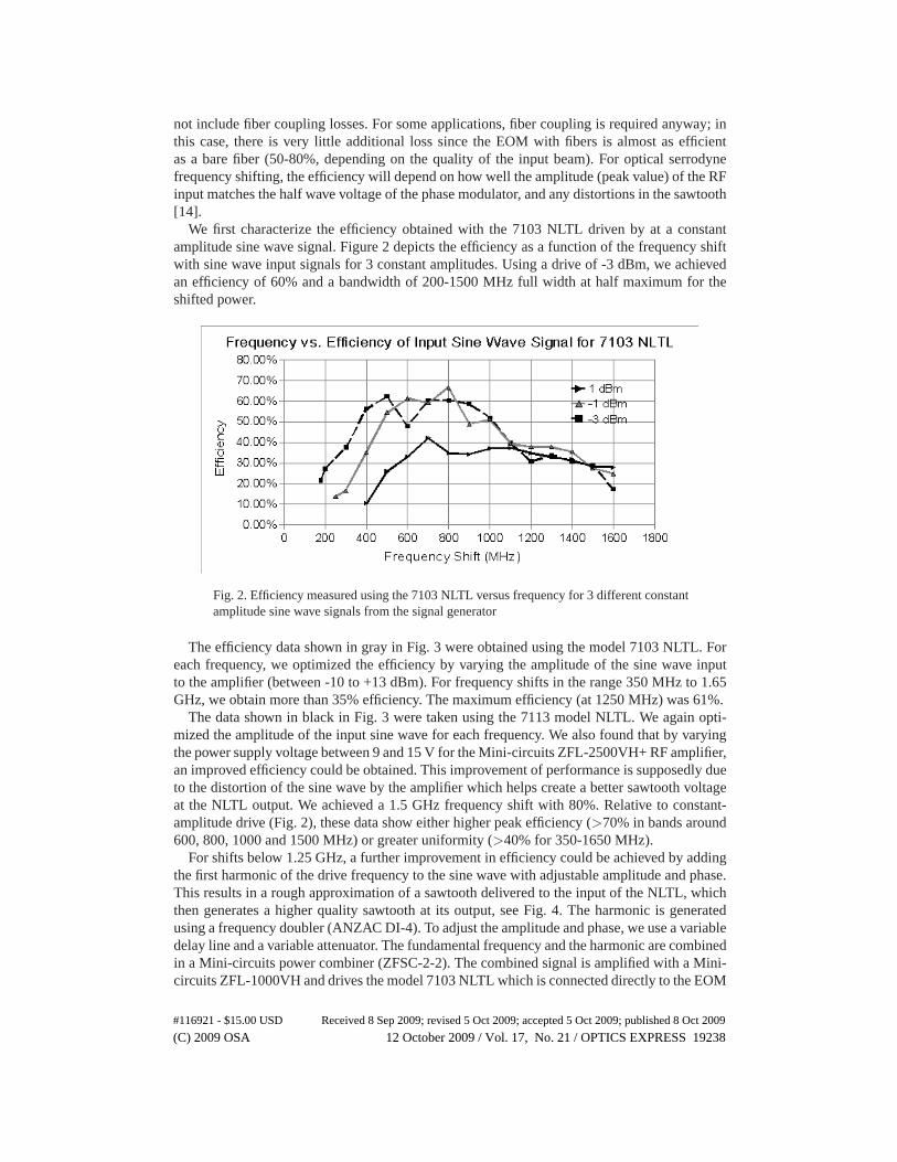
We first characterize the efficiency obtained with the 7103 NLTL driven by at a constantamplitude sine wave signal. Figure 2 depicts the efficiency as a function of the frequency shiftwith sine wave input signals for 3 constant amplitudes. Using a drive of -3 dBm, we achievedan efficiency of 60% and a bandwidth of 200-1500 MHz full width at half maximum for theshifted power.
Fig. 2. Efficiency measured using the 7103 NLTL versus frequency for 3 different constantamplitude sine wave signals from the signal generator
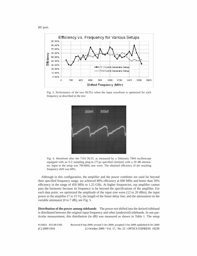
The efficiency data shown in gray in Fig. 3 were obtained using the model 7103 NLTL. Foreach frequency, we optimized the efficiency by varying the amplitude of the sine wave inputto the amplifier (between -10 to +13 dBm). For frequency shifts in the range 350 MHz to 1.65GHz, we obtain more than 35% efficiency. The maximum efficiency (at 1250 MHz) was 61%.
The data shown in black in Fig. 3 were taken using the 7113 model NLTL. We again opti-mized the amplitude of the input sine wave for each frequency. We also found that by varyingthe power supply voltage between 9 and 15 V for the Mini-circuits ZFL-2500VH+ RF amplifier,an improved efficiency could be obtained. This improvement of performance is supposedly dueto the distortion of the sine wave by the amplifier which helps create a better sawtooth voltageat the NLTL output. We achieved a 1.5 GHz frequency shift with 80%. Relative to constant-amplitude drive (Fig. 2), these data show either higher peak efficiency (>70% in bands around600, 800, 1000 and 1500 MHz) or greater uniformity (>40% for 350-1650 MHz).
For shifts below 1.25 GHz, a further improvement in efficiency could be achieved by addingthe first harmonic of the drive frequency to the sine wave with adjustable amplitude and phase.This results in a rough approximation of a sawtooth delivered to the input of the NLTL, whichthen generates a higher quality sawtooth at its output, see Fig. 4. The harmonic is generatedusing a frequency doubler (ANZAC DI-4). To adjust the amplitude and phase, we use a variabledelay line and a variable attenuator. The fundamental frequency and the harmonic are combinedin a Mini-circuits power combiner (ZFSC-2-2). The combined signal is amplified with a Mini-circuits ZFL-1000VH and drives the model 7103 NLTL which is connected directly to the EOM
#116921 - $15.00 USD Received 8 Sep 2009; revised 5 Oct 2009; accepted 5 Oct 2009; published 8 Oct 2009
(C) 2009 OSA 12 October 2009 / Vol. 17, No. 21 / OPTICS EXPRESS 19238
RF port.
Fig. 3. Performance of the two NLTLs when the input waveform is optimized for eachfrequency as described in the text
Fig. 4. Waveform after the 7103 NLTL as measured by a Tektronix 7904 oscilloscopeequipped with an S-2 sampling plug-in (75 ps specified risetime) with a 20 dB attenua-tor. Input to the setup was 700 MHz sine wave. The obtained efficiency of the resultingfrequency shift was 68%.
Although in this configuration, the amplifier and the power combiner are used far beyondtheir specified frequency range, we achieved 80% efficiency at 600 MHz and better than 50%efficiency in the range of 450 MHz to 1.25 GHz. At higher frequencies, our amplifier cannotpass the harmonic because its frequency is far beyond the specifications of the amplifier. Foreach data point, we optimized the amplitude of the input sine wave (12 to 20 dBm), the inputpower to the amplifier (7 to 15 V), the length of the linear delay line, and the attenuation on thevariable attenuator (0 to 7 dB), see Fig. 5.
Distribution of the power among sidebands The power not shifted into the desired sidebandis distributed between the original input frequency and other (undesired) sidebands. In one par-ticular measurement, this distribution (in dB) was measured as shown in Table 1. The setup
#116921 - $15.00 USD Received 8 Sep 2009; revised 5 Oct 2009; accepted 5 Oct 2009; published 8 Oct 2009
(C) 2009 OSA 12 October 2009 / Vol. 17, No. 21 / OPTICS EXPRESS 19239
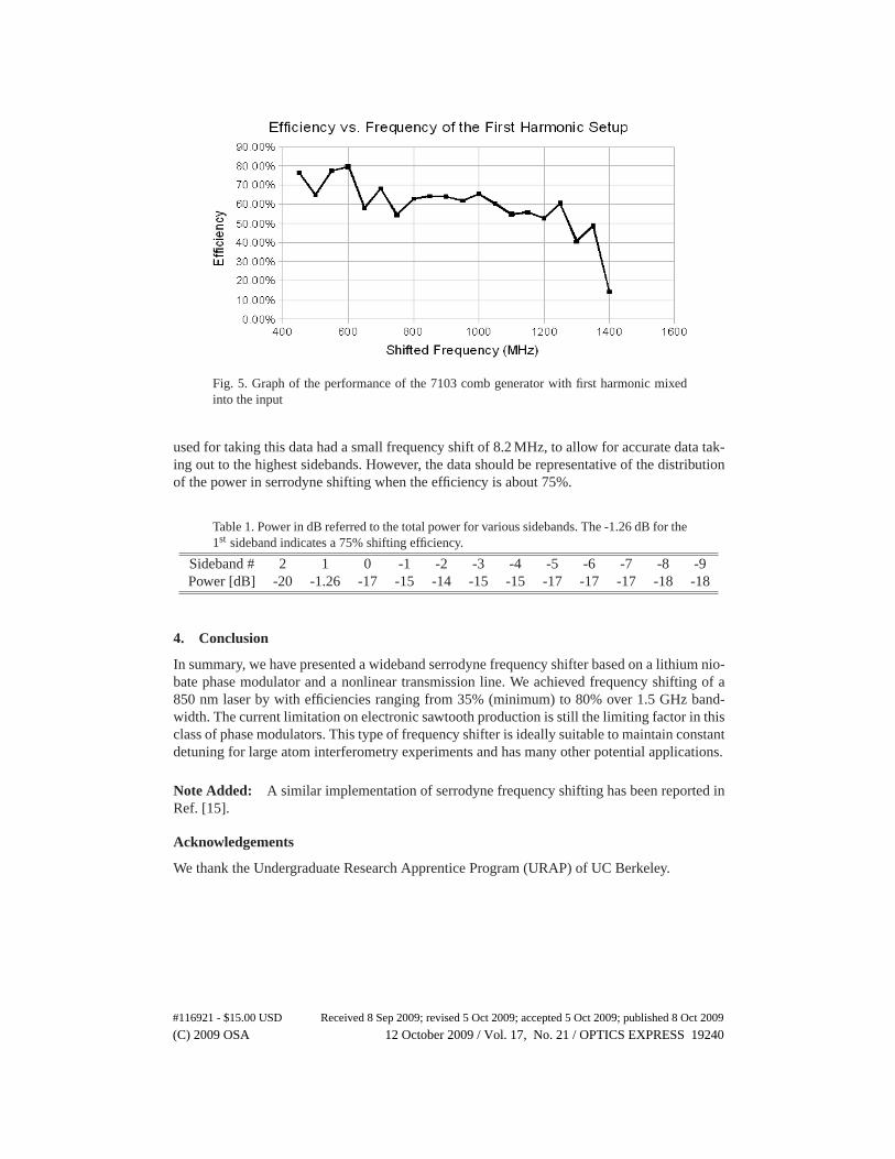
Fig. 5. Graph of the performance of the 7103 comb generator with first harmonic mixedinto the input
used for taking this data had a small frequency shift of 8.2 MHz, to allow for accurate data tak-ing out to the highest sidebands. However, the data should be representative of the distributionof the power in serrodyne shifting when the efficiency is about 75%.
Table 1. Power in dB referred to the total power for various sidebands. The -1.26 dB for the1st sideband indicates a 75% shifting efficiency.
Sideband # 2 1 0 -1 -2 -3 -4 -5 -6 -7 -8 -9Power [dB] -20 -1.26 -17 -15 -14 -15 -15 -17 -17 -17 -18 -18
4. Conclusion
In summary, we have presented a wideband serrodyne frequency shifter based on a lithium nio-bate phase modulator and a nonlinear transmission line. We achieved frequency shifting of a850 nm laser by with efficiencies ranging from 35% (minimum) to 80% over 1.5 GHz band-width. The current limitation on electronic sawtooth production is still the limiting factor in thisclass of phase modulators. This type of frequency shifter is ideally suitable to maintain constantdetuning for large atom interferometry experiments and has many other potential applications.
Note Added: A similar implementation of serrodyne frequency shifting has been reported inRef. [15].
Acknowledgements
We thank the Undergraduate Research Apprentice Program (URAP) of UC Berkeley.
#116921 - $15.00 USD Received 8 Sep 2009; revised 5 Oct 2009; accepted 5 Oct 2009; published 8 Oct 2009
(C) 2009 OSA 12 October 2009 / Vol. 17, No. 21 / OPTICS EXPRESS 19240