Embed Size (px)
Citation preview

INSTRUCTION MANUAL
WIDE RANGE SPEAKER CS-154BS
1. SAFETY PRECAUTIONS ........................... 2
2. GENERAL DESCRIPTION
AND FEATURES ........................................ 3
3. IMPEDANCE CHANGE .............................. 4
4. WIRING4.1. When No Bridge Connection
is Required ......................................... 44.2. When Bridge Connection
is Required ......................................... 5
5. INSTALLATION PRECAUTION ................. 7
6. DIMENSIONAL DIAGRAM ......................... 8
7. WIRING DIAGRAM ..................................... 8
8. FREQUENCY RESPONSE ......................... 8
9. SPECIFICATIONS ...................................... 9
Thank you for purchasing TOA's Wide Range Speaker. Please carefully follow the instructions in this manual to ensure long, trouble-free use of your equipment.
TABLE OF CONTENTS
Traceability Information for Europe (EMC directive 2004/108/EC)
Manufacturer:TOA Corporation7-2-1, Minatojima Nakamachi, Chuo-ku, Kobe, Hyogo, Japan
Authorized representative:TOA Electronics Europe GmbHSuederstrasse 282, 20537 Hamburg,Germany
2
When Installing the Unit
• Refer all installation work to the dealer from whomthe speaker was purchased. Installation workrequires extensive technical knowledge andexperience. The speaker may fall off if incorrectlyinstalled, resulting in possible personal injury.
• Install the speaker only in a location that canstructurally support the full weight of the unit andmounting bracket. Doing otherwise may result inthe speaker falling down and causing personalinjury and/or property damage.
• When installing the speaker in the snowy area,take appropriate measures to prevent snow fromlying on the speaker. If the snow lies on it, thespeaker may fall, causing personal injuries.
• Do not use other methods than specified to installthe speaker. Extreme force is applied to thespeaker and the speaker could fall off, possiblyresulting in personal injuries.
• Use screws that are appropriate for the ceiling's orwall's material and structure. Failure to do so maycause the speaker to fall, resulting in materialdamage and possible personal injury.
• Ensure that all screws are securely tightened. Ifthey are loose after installation, the speaker couldfall down, possibly resulting in personal injury.
• Do not mount the speaker in locations exposed toconstant vibration. The speaker or its mounts canbe damaged by excessive vibration, potentiallycausing the speaker to fall, which could result inpersonal injury.
• Do not use anti-rust lubricant. If it contacts resin orrubber parts, they could deteriorate and cause thespeaker to fall, possibly resulting in personal injury.
• Avoid installing the speaker near seaside or inlocations exposed to corrosive gas. The speaker orits parts may be subject to corrosion, which mightcause it to fall or result in personal injury.
• Do not install the speaker in indoor swimming poolsor such locations where liquid chemicals are used.The parts deteriorate if corroded, causing thespeaker to fall, which could result in personalinjury.
When the Unit is in Use
• If any of the following irregularit ies occurs,immediately switch off the amplifier's power, andinform the shop from where the speaker waspurchased. Further using the speaker may result infire or electric shock.
· If you detect smoke or a strange smell comingfrom the speaker
· If water or any metallic object gets into thespeaker
· If the speaker falls, or the speaker case breaks
• To prevent a fire or electric shock, never open norremove the speaker case. Refer all servicing toyour nearest TOA dealer.
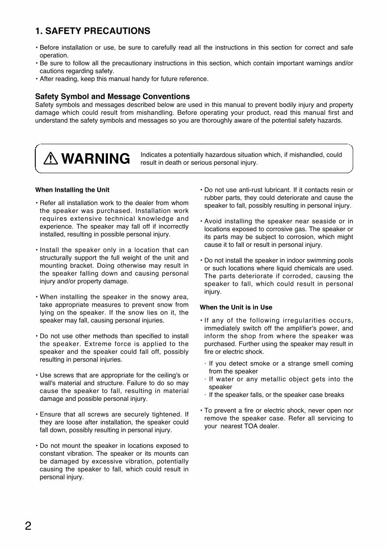
1. SAFETY PRECAUTIONS
• Before installation or use, be sure to carefully read all the instructions in this section for correct and safeoperation.
• Be sure to follow all the precautionary instructions in this section, which contain important warnings and/orcautions regarding safety.
• After reading, keep this manual handy for future reference.
Safety Symbol and Message Conventions Safety symbols and messages described below are used in this manual to prevent bodily injury and propertydamage which could result from mishandling. Before operating your product, read this manual first andunderstand the safety symbols and messages so you are thoroughly aware of the potential safety hazards.
Indicates a potentially hazardous situation which, if mishandled, couldresult in death or serious personal injury. WARNING
3
When Installing the Unit
• Avoid touching the speaker's sharp metal edge toprevent injury.
• To avoid electric shocks, be sure to switch off theamplifier's power when connecting speakers.
When the Unit is in Use
• Do not operate the speaker for an extended periodof time with the sound distorting. Doing so maycause the speaker to heat, resulting in a fire.
• Do not stand or sit on, nor hang down from thespeaker as this may cause it to fall down or drop,result ing in personal injury and/or propertydamage.
• Have the speaker checked periodically by the shopfrom where it was purchased. Failure to do so mayresult in corrosion or damage to the speaker or themounts that could cause it to fall, possibly causingpersonal injury.
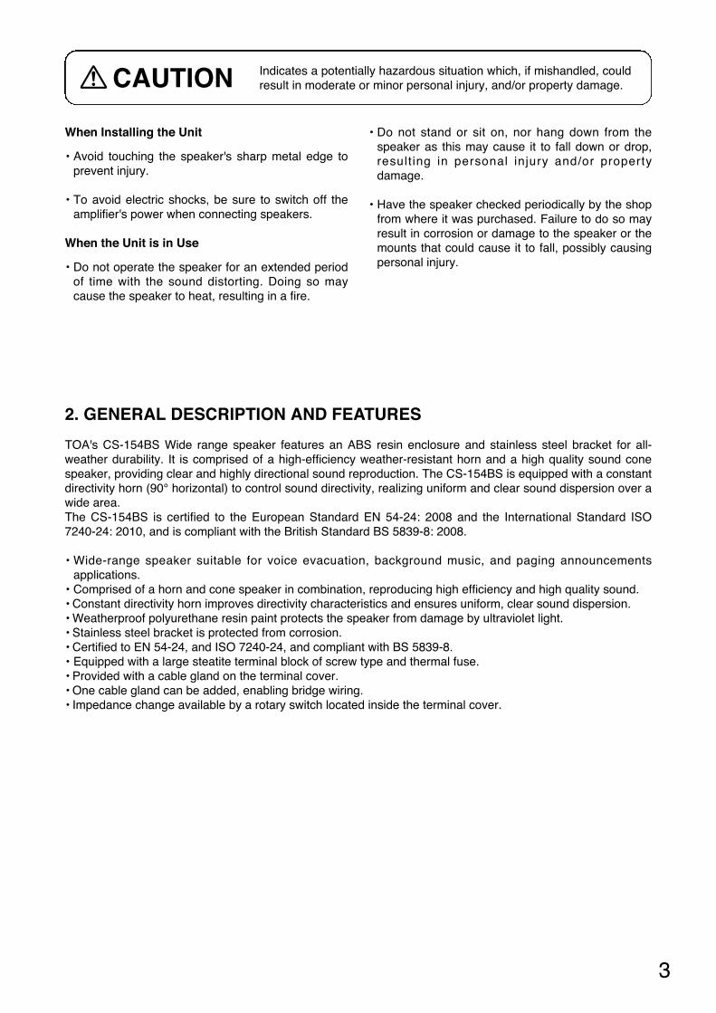
Indicates a potentially hazardous situation which, if mishandled, couldresult in moderate or minor personal injury, and/or property damage.CAUTION
2. GENERAL DESCRIPTION AND FEATURES
TOA's CS-154BS Wide range speaker features an ABS resin enclosure and stainless steel bracket for all-weather durability. It is comprised of a high-efficiency weather-resistant horn and a high quality sound conespeaker, providing clear and highly directional sound reproduction. The CS-154BS is equipped with a constantdirectivity horn (90° horizontal) to control sound directivity, realizing uniform and clear sound dispersion over awide area.The CS-154BS is certified to the European Standard EN 54-24: 2008 and the International Standard ISO7240-24: 2010, and is compliant with the British Standard BS 5839-8: 2008.
• Wide-range speaker suitable for voice evacuation, background music, and paging announcementsapplications.
• Comprised of a horn and cone speaker in combination, reproducing high efficiency and high quality sound.• Constant directivity horn improves directivity characteristics and ensures uniform, clear sound dispersion.• Weatherproof polyurethane resin paint protects the speaker from damage by ultraviolet light.• Stainless steel bracket is protected from corrosion.• Certified to EN 54-24, and ISO 7240-24, and compliant with BS 5839-8.• Equipped with a large steatite terminal block of screw type and thermal fuse.• Provided with a cable gland on the terminal cover.• One cable gland can be added, enabling bridge wiring.• Impedance change available by a rotary switch located inside the terminal cover.
EARTH
HOT
COM
COM
HOT
EARTH
Screw terminal Speaker cable
4
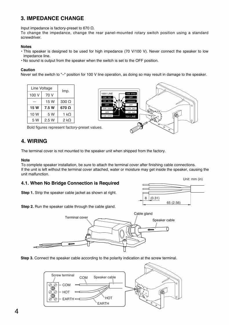
3. IMPEDANCE CHANGE
Input impedance is factory-preset to 670 Ω.To change the impedance, change the rear panel-mounted rotary switch position using a standardscrewdriver.
Notes• This speaker is designed to be used for high impedance (70 V/100 V). Never connect the speaker to low
impedance line. • No sound is output from the speaker when the switch is set to the OFF position.
CautionNever set the switch to "–" position for 100 V line operation, as doing so may result in damage to the speaker.
100 V 70 VImp.
— 330 Ω
670 Ω
1 kΩ
2 kΩ
15 W
10 W
5 W
15 W
7.5 W
5 W
2.5 W
Line Voltage
Bold figures represent factory-preset values.
100V LINE 15W 670Ω
10W 1kΩ
5W 2kΩ
OFF
OFF
OFF
2.5W 2kΩ
5W 1kΩ
15W 330Ω
OFF
7.5W 670Ω 70V LINE
4. WIRING
The terminal cover is not mounted to the speaker unit when shipped from the factory.
NoteTo complete speaker installation, be sure to attach the terminal cover after finishing cable connections.If the unit is left without the terminal cover attached, water or moisture may get inside the speaker, causing theunit malfunction.
4.1. When No Bridge Connection is Required
Step 1. Strip the speaker cable jacket as shown at right.
Step 2. Run the speaker cable through the cable gland.
Step 3. Connect the speaker cable according to the polarity indication at the screw terminal.
65 (2.56)8 (0.31)
Unit: mm (in)
Terminal coverSpeaker cable
Cable gland
5
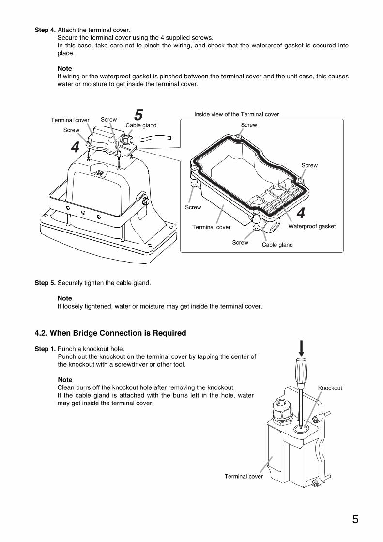
Step 4. Attach the terminal cover.Secure the terminal cover using the 4 supplied screws.In this case, take care not to pinch the wiring, and check that the waterproof gasket is secured intoplace.
NoteIf wiring or the waterproof gasket is pinched between the terminal cover and the unit case, this causeswater or moisture to get inside the terminal cover.
Step 5. Securely tighten the cable gland.
NoteIf loosely tightened, water or moisture may get inside the terminal cover.
ScrewCable gland
Screw
Terminal cover
4
5
Inside view of the Terminal cover
Waterproof gasket
Screw
Screw
Screw
Terminal cover
Cable gland
Screw
4
4.2. When Bridge Connection is Required
Step 1. Punch a knockout hole.Punch out the knockout on the terminal cover by tapping the center of the knockout with a screwdriver or other tool.
NoteClean burrs off the knockout hole after removing the knockout.If the cable gland is attached with the burrs left in the hole, watermay get inside the terminal cover.
Knockout
Terminal cover

6
Step 2. Mount the cable gland to be added.
Notes• Prepare the cable gland of PG 13.5 size separately.• Ensure that the cable gland is securely tightened. If loosely tightened, water may get inside the
terminal cover.
Cable gland
Waterproof gasket
Nut
Terminal cover
Step 3. Strip the speaker cable jacket. (Refer to page 4, Step 1.)
Step 4. Run one each of speaker cables through the cable gland.
Terminal cover
Speaker cables
Cable glands
Step 5. Connect the speaker cables with the same polarity to each terminal according to the polarity indicationat the screw terminal.
EARTH
HOT
COM
COM
HOTEARTH
Screw terminal Speaker cables

7
• Do not install the speaker face-up from a horizontal plane nor in such a way that the paper cone is exposedto direct sunlight.If water accumulates on the paper cone, or ultraviolet rays are radiated on it, this may cause the paper coneto deteriorate, leading to speaker malfunction.
5. INSTALLATION PRECAUTION
• The mounting bracket cannot be adjusted within the angle shown in the figure below, which differsdepending on the number of cable glands mounted on the terminal cover as follows.
· When 1 cable gland is mounted: 25° range not adjustable· When 2 cable glands are mounted (one is additional): 40° range not adjustable
• Be sure that the bolt projection length from wall surface is less than 15 mm (0.59"). If the length is increasedbeyond 15 mm (0.59"), the bolt touches the speaker's terminal cover, causing the speaker mounting angle tobe limited further.
Within 90°
25°
Less
than
15
mm
(0.
59")
40°
Step 6. Attach the terminal cover.Secure the terminal cover using the 4 supplied screws.In this case, take care not to pinch the wiring, and check that the waterproof gasket is secured intoplace.
NoteIf wiring or the waterproof gasket is pinched between the terminal cover and the unit case, this causeswater or moisture to get inside the terminal cover.
Screw
Cable glandsScrew
Terminal cover
4
5
Inside view of theTerminal cover
Waterproof gasket
Screw
Screw
Screw
Terminal coverCable glands
Screw
4
Step 7. Securely tighten the cable glands.
NoteIf loosely tightened, water or moisture may get inside the terminal cover.
8
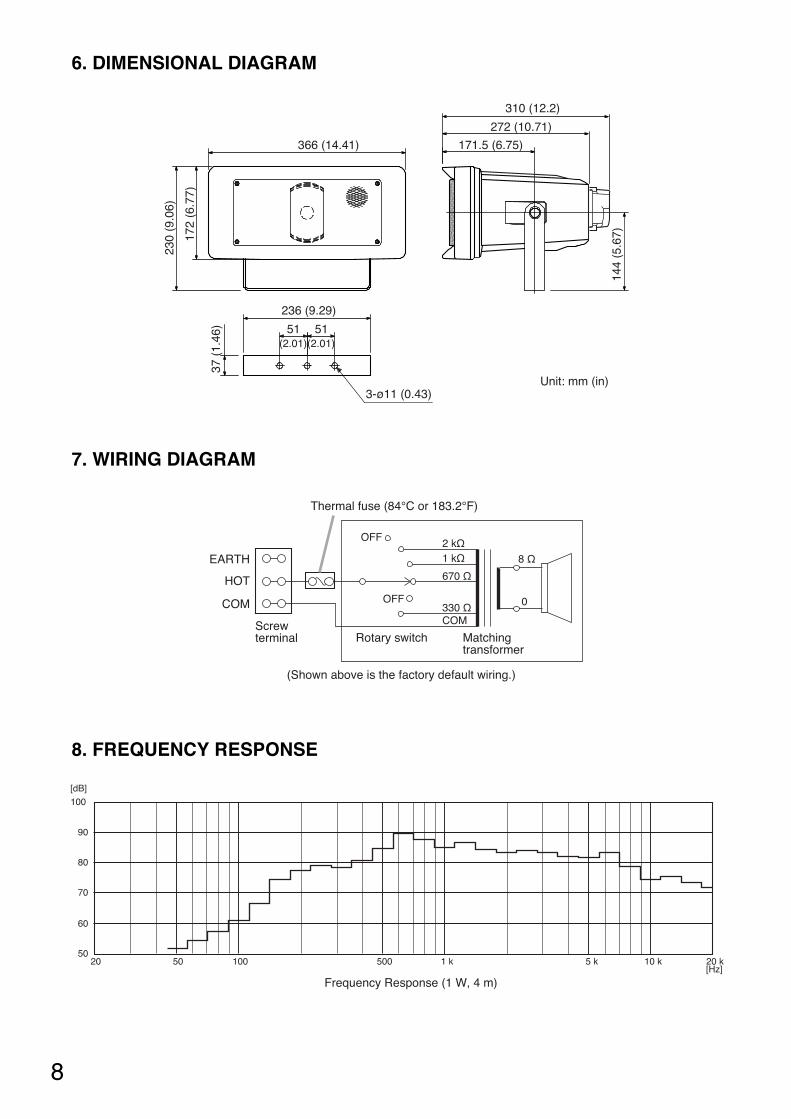
6. DIMENSIONAL DIAGRAM
7. WIRING DIAGRAM
1 kΩ2 kΩ
670 Ω
330 ΩOFF
OFF
COM
8 Ω
0
EARTH
HOT
COM
Screwterminal Rotary switch Matching
transformer
Thermal fuse (84°C or 183.2°F)
(Shown above is the factory default wiring.)
272 (10.71)
310 (12.2)
366 (14.41)
51(2.01)(2.01)
51
236 (9.29)
3-ø11 (0.43)
171.5 (6.75)
144
(5.6
7)
230
(9.0
6)
37 (
1.46
)
172
(6.7
7)
Unit: mm (in)
8. FREQUENCY RESPONSE
[dB]
5020 50 100 500 1 k 5 k 10 k 20 k
[Hz]
90
80
70
60
100
Frequency Response (1 W, 4 m)
9
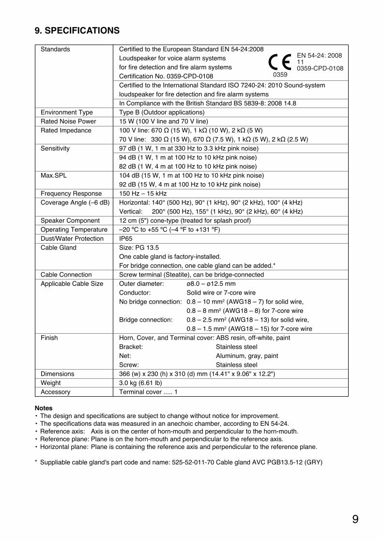
9. SPECIFICATIONS
Standards Certified to the European Standard EN 54-24:2008Loudspeaker for voice alarm systems for fire detection and fire alarm systemsCertification No. 0359-CPD-0108Certified to the International Standard ISO 7240-24: 2010 Sound-system loudspeaker for fire detection and fire alarm systemsIn Compliance with the British Standard BS 5839-8: 2008 14.8
Environment Type Type B (Outdoor applications)Rated Noise Power 15 W (100 V line and 70 V line)Rated Impedance 100 V line: 670 Ω (15 W), 1 kΩ (10 W), 2 kΩ (5 W)
70 V line: 330 Ω (15 W), 670 Ω (7.5 W), 1 kΩ (5 W), 2 kΩ (2.5 W)Sensitivity 97 dB (1 W, 1 m at 330 Hz to 3.3 kHz pink noise)
94 dB (1 W, 1 m at 100 Hz to 10 kHz pink noise)82 dB (1 W, 4 m at 100 Hz to 10 kHz pink noise)
Max.SPL 104 dB (15 W, 1 m at 100 Hz to 10 kHz pink noise)92 dB (15 W, 4 m at 100 Hz to 10 kHz pink noise)
Frequency Response 150 Hz – 15 kHzCoverage Angle (–6 dB) Horizontal: 140° (500 Hz), 90° (1 kHz), 90° (2 kHz), 100° (4 kHz)
Vertical: 200° (500 Hz), 155° (1 kHz), 90° (2 kHz), 60° (4 kHz)Speaker Component 12 cm (5") cone-type (treated for splash proof)Operating Temperature –20 ºC to +55 ºC (–4 ºF to +131 ºF)Dust/Water Protection IP65Cable Gland Size: PG 13.5
One cable gland is factory-installed.For bridge connection, one cable gland can be added.*
Cable Connection Screw terminal (Steatite), can be bridge-connectedApplicable Cable Size Outer diameter: ø8.0 – ø12.5 mm
Conductor: Solid wire or 7-core wireNo bridge connection: 0.8 – 10 mm2 (AWG18 – 7) for solid wire,
0.8 – 8 mm2 (AWG18 – 8) for 7-core wireBridge connection: 0.8 – 2.5 mm2 (AWG18 – 13) for solid wire,
0.8 – 1.5 mm2 (AWG18 – 15) for 7-core wireFinish Horn, Cover, and Terminal cover: ABS resin, off-white, paint
Bracket: Stainless steelNet: Aluminum, gray, paintScrew: Stainless steel
Dimensions 366 (w) x 230 (h) x 310 (d) mm (14.41" x 9.06" x 12.2")Weight 3.0 kg (6.61 lb)Accessory Terminal cover ..... 1
Notes• The design and specifications are subject to change without notice for improvement. • The specifications data was measured in an anechoic chamber, according to EN 54-24.• Reference axis: Axis is on the center of horn-mouth and perpendicular to the horn-mouth.• Reference plane: Plane is on the horn-mouth and perpendicular to the reference axis.• Horizontal plane: Plane is containing the reference axis and perpendicular to the reference plane.
* Suppliable cable gland's part code and name: 525-52-011-70 Cable gland AVC PGB13.5-12 (GRY)
EN 54-24: 2008110359-CPD-0108
0359


URL: http://www.toa.jp/
533-06-246-30