Embed Size (px)
Citation preview
By P. J. WALKER*
Wide Range Electrostatic Loudspeakers
I.-Principles of Design for Operation at Low as well as High Frequencies withNegligible Distortionÿ
A closer examination of underlying principles leads to theconclusion that the electrostatic loudspeaker may wellsupersede the moving coil for high-quality soundreproduction. Designs recently developed have proved to becapable of reproducing the full audio-frequency range. withharmonic. distortions no higher than those of the associatedamplifier.
EVERY loudspeaker designer must, at some time or other,have looked longingly at the electrostatic principal of driveas a solution to his problems of improving quality ofreproduction. The movement of a diaphragm driven all overits surface is entirely predictable. The diaphragm can be aslight as required. The impedances influencing performancecan be predominantly acoustic and-since there are no shaperestrictions--entirely under the control of the designer.
What has held it back? First, the fact thatin its generallyknown form it is intrinsically non-linear and even in apush-pull construction linearity can only be approached forsmall amplitudes. Secondly, in order to obtain adequatesensitivity the available gap is small; the diaphragmmovement limited and largely stiffness controlled, bothfactors restricting its use to high frequencies. Thirdly, thatbeing essentially a capacitive electrical load, it is difficult tomatch to an amplifier.
The first of these objections, that of non-linearity, can beremoved completely by an expedient which is spectacularin its effectiveness and simplicity. The second and thirddifficulties will resolve themselves, as we shall see later,when the designer makes his choice of the interdependentmechanical, acoustical and electrical variables.
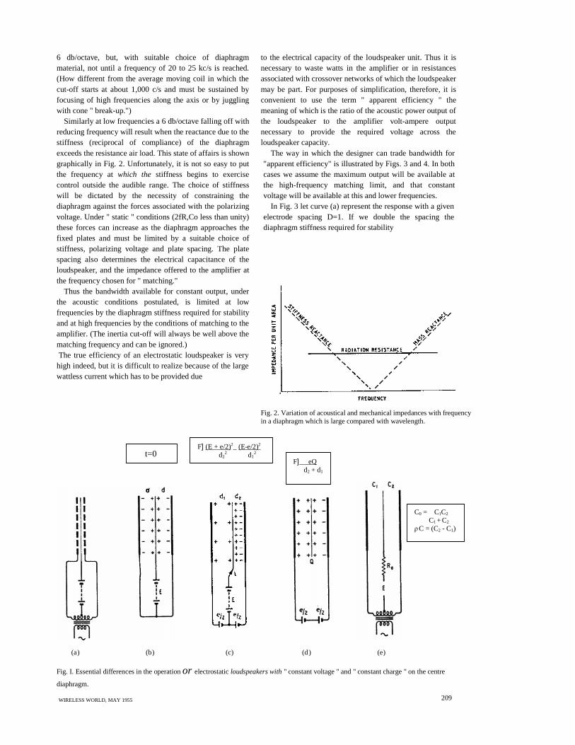
Fig. 1 (a) shows diagrammatically the connection of aconventional electrostatic loudspeaker in which thepolarizing voltage is applied to the centre diaphragm and thesignal in push-pull to the outer perforated fixed plates. Underconditions of no signal, Fig. 1 (b), and assuming thediaphragm to be central, there will be equal and oppositeattractive forces on the diaphragm If one fixed plate is nowmade positive and the other negative so that the diaphragmwill be deflected to the right, the effective capacitance willincrease, and to satisfy the relationship Q =CE the charge Qwill also increase and will be supplied by a current i duringthe movement. The force acting on the diaphragm per unitarea will, however, be proportional to
ÿ
The relationshipwill be non-linear. Note that the charge Q,although varying, does not enter directly into the relation.
Suppose that after having charged the diaphragmelectrode the source of polarizing potential is discon-
* Acoustical Manufacturing Co.,
208
nected (Fig. 1(d)). The diaphragm now carries a constantcharge Q which experiences a force propor- to the productof the field intensity and the charge. This force will beindependent of the position of the diaphragm between theplates since both Q and the distance between plates areconstants; the only variable is the applied voltage e. Notethat the difference betweend1 and d:, although varying,does not enter into the relation.
The above is perhaps an over-simplification, but itshows that distortion is not necessarily inherent in theelectrostatic principle.
The " constant Q " method of operation has another veryimportant advantage in that it reduces the risk of collapse,which occurs at large amplitudes with the conventionalmethod of connection, when the negative stiffness resultingfrom electrical attraction exceeds the positive mechanicalstiffness of the diaphragm. As the diaphragm approachesone of the fixed plates the capacitance is increased, but asthe charge Q has been assumed constant, E must fall sinceE=Q/C.
Professor F. V. Hunt of Harvard University has shownÿthat the criterion for dynamic stability under largeexcursions is that the time constant RoCo of the chargingcircuit (Fig. 1(e)) should be large compared with 1/2f, thehalf-period of the applied frequency. This also supplies thecondition for low distortion and Professor Hunt gives theresults of measurements (Fig. 6.14, p. 212, loc.cit.)showing the dependence of second harmonic distortion onboth the degree of unbalance due to displacement of thecentral electrode (in terms of� C/C) and of the ratio of timeconstant to half period 2fR0C0. Even when this latterparameter was reduced to unity, and the diaphragmdisplaced by a distance equivalent to a capacity unbalanceof 25 per cent, the second harmonic did not exceed 0.5 percent, when driven at 150 c/s by 780 V r.m.s. (plate-to- witha polarizing voltage of 500. Third and higher harmonicswere always less than the second.
So much for the driving mechanism; it now remains tosee how it fares when coupled to the air and to an amplifier.
It will help in understanding the broad principlesinvolved if we start by considering a loudspeaker whosediaphragm is large compared with the longest wavelengthof sound to be reproduced. Under these conditions the massreactance of the air load on both sides of the diaphragm canbe neglected and the impedance per unit area 2ρc offered tothe motion of the diaphragm is predominantly resistive(ρc=42 mechanical ohms per cm2). With constant voltagedriving the diaphragm the force will be proportional to theapplied signal voltage and independent of frequency. If theload is resistive the velocity, and also the acoustic poweroutput, will be independent of frequency.
At very high frequencies the mass reactance of thediaphragm can exceed the radiation resistance and willcause a falling off in velocity when the force remainsconstant; the acoustic output will then decline by
ÿ " El ectroacoustics " b y F. V. Hunt, chapter 6.Published by John Wiley & Sons (Chapman & Hall).
WIRELESSWORLD, MAY 1955
(E + e/2)2 - (E - e/2)2d2
2 d12
to the electrical capacity of the loudspeaker unit. Thus it isnecessary to waste watts in the amplifier or in resistancesassociated with crossover networks of which the loudspeakermay be part. For purposes of simplification, therefore, it isconvenient to use the term " apparent efficiency " themeaning of which is the ratio of the acoustic power output ofthe loudspeaker to the amplifier volt-ampere outputnecessary to provide the required voltage across theloudspeaker capacity.
The way in which the designer can trade bandwidth for"apparent efficiency" is illustrated by Figs. 3 and 4. In bothcases we assume the maximum output will be available atthe high-frequency matching limit, and that constantvoltage will be available at this and lower frequencies.
In Fig. 3 let curve (a) represent the response with a givenelectrode spacing D=1. If we double the spacing thediaphragm stiffness required for stability
Fig. 2. Variation of acoustical and mechanical impedances with frequencyin a diaphragm which is large compared with wavelength.
6 db/octave, but, with suitable choice of diaphragmmaterial, not until a frequency of 20 to 25 kc/s is reached.(How different from the average moving coil in which thecut-off starts at about 1,000 c/s and must be sustained byfocusing of high frequencies along the axis or by jugglingwith cone " break-up.")
Similarly at low frequencies a 6 db/octave falling off withreducing frequency will result when the reactance due to thestiffness (reciprocal of compliance) of the diaphragmexceeds the resistance air load. This state of affairs is showngraphically in Fig. 2. Unfortunately, it is not so easy to putthe frequency atwhich the stiffness begins to exercisecontrol outside the audible range. The choice of stiffnesswill be dictated by the necessity of constraining thediaphragm against the forces associated with the polarizingvoltage. Under " static " conditions (2fR,Co less than unity)these forces can increase as the diaphragm approaches thefixed plates and must be limited by a suitable choice ofstiffness, polarizing voltage and plate spacing. The platespacing also determines the electrical capacitance of theloudspeaker, and the impedance offered to the amplifier atthe frequency chosen for " matching."
Thus the bandwidth available for constant output, underthe acoustic conditions postulated, is limited at lowfrequencies by the diaphragm stiffness required for stabilityand at high frequencies by the conditions of matching to theamplifier. (The inertia cut-off will always be well above thematching frequency and can be ignored.)The true efficiency of an electrostatic loudspeaker is very
high indeed, but it is difficult to realize because of the largewattless current which has to be provided due
WIRELESS WORLD, MAY 1955 209
Fig. I. Essential differences in the operationor electrostaticloudspeakers with" constantvoltage " and " constant charge " on the centre
diaphragm.
(a) (b) (c) (d) (e)
F] eQd2 + d1
C0 = C1C2
C1 + C2
� C = (C2 - C1)
t=0F] (E + e/2)2_ (E-e/2)2
d22 d1
2
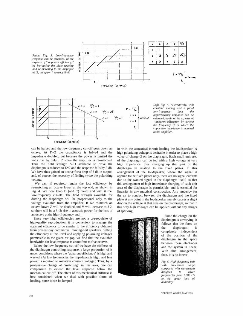
Right: Fig. 3. Low-frequencyresponse can be extended,of theexpense of " apparent efficiency,"by increasing the plate spacingand re-matching to the amplifierat f2, the upper frequency limit.
can be halved and the low-frequency cut-off goes down anoctave. At D=2 the capacitance is halved and theimpedance doubled, but because the power is limited thevolts rise by only J 2 when the amplifier is re-matched.Thus the field strength V/D available to drive thediaphragm is reduced to J2/2 and the response falls by 3 db.We have thus gained an octave for a drop of 3 db in output,and, of course, the necessity of finding twice the polarizingvoltage.
We can, if required, regain the lost efficiency byre-matching an octave lower at the top end, as shown inFig. 4. We now keep D (and C) fixed, and with it the.low-frequency cut-off. The field strength available fordriving the diaphragm will be proportional only to thevoltage available from the amplifier. If we re-match anoctave lower Z will be doubled and V will increase to J 2,so there will be a 3-db rise in acoustic power for the loss ofan octave at the high-frequency end.
Since very high efficiencies are not a pre-requisite ofhigh-quality reproduction, it is convenient to arrange theapparent efficiency to be similar to the efficiency obtainedfrom present-day commercial moving-coil speakers. Settingthe efficiency at this level and applying polarizing voltagespermissible in the given air gap, we find that the availablebandwidth for level response is about four to five octaves.
Below the low-frequency cut-off we have the stiffness ofthe diaphragm controlling response, a large proportion of itunder conditions where the "apparent efficiency" is high andwasted. (At low frequencies the impedance is high, and lesspower is required to maintain constant voltage.) Thus, by aprogressive change of "matching" in this area, one cancompensate to extend the level response below themechanical cut-off. The effect of this mechanical stiffness isbest considered when we deal with possible forms ofloading, since it can be lumped
in with the acoustical circuit loading the loudspeaker. Ahigh polarizing voltage is desirable in orderto place a highvalue of charge Q on the diaphragm. Each small unit areaof the diaphragm can be fed with a high voltage at veryhigh impedance, thus charging up that part of thediaphragm in relation to the fixed plates. In thisarrangement of the loudspeaker, where the signal isapplied to the fixed plates only, there are no signal currentsdue to the wanted signal in the diaphragm itself, so thatthis arrangement of high-impedance charging of each unitarea of the diaphragm is permissible, and is essential forlinearity in any practical construction. Any tendency forthe air to conduct between the diaphragm and the fixedplate at any point in the loudspeaker merely causes a slightdrop in the voltage at that area on the diaphragm, so that inthis way high voltages can be applied without any dangerof sparking.
Since the charge on thediaphragm is unvarying, itfollows that the force onthe diaphragm iscompletely independentof the position of thediaphragm in the spacebetween these electrodesand the system in linear.With this arrangement,then, it is no longer
Fig. 5. High-frequency unitwith dimensions largecompared with wavelengthdesigned to coverfrequencies from 1,000 c/sto the upper limit ofaudibility.
Left: Fig. 4. Alternatively, withconstant spacing and a facedlow-frequency limit thehighfrequency response con 6eextended, again at the expenseof" apparent efficiency,' by varyingthe frequencyf2 at which thecapacitive impedance is matchedto the amplifier.
WIRELESS WORLD, MAY 1955210
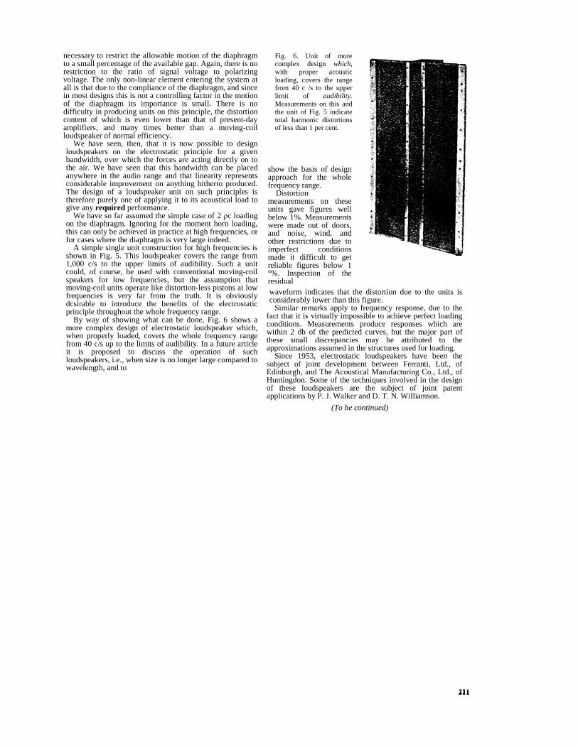
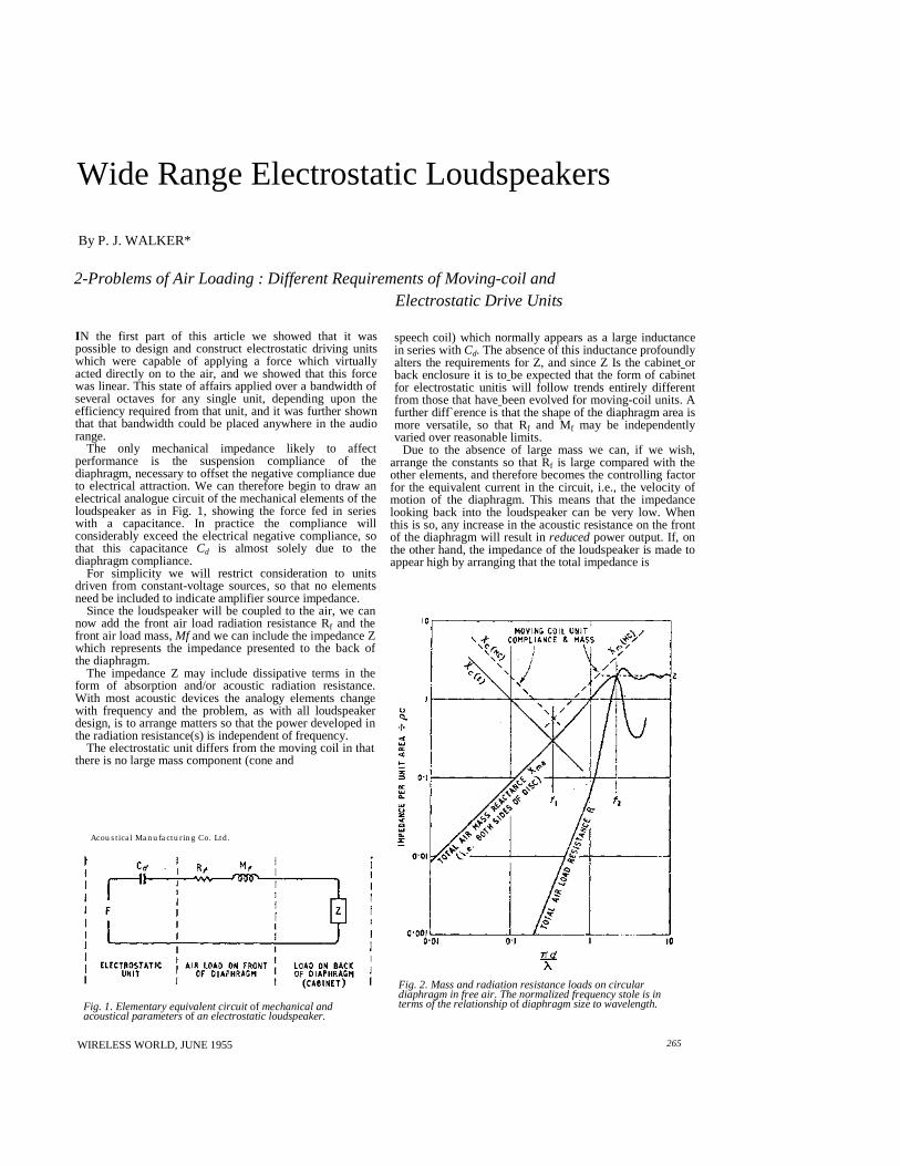
Fig. 6. Unit of morecomplex design which,with proper acousticloading, covers the rangefrom 40 c /s to the upperlimit of audibility.Measurements on this andthe unit of Fig. 5 indicatetotal harmonic distortionsof less than 1 per cent.
show the basis of designapproach for the wholefrequency range.
Distortionmeasurements on theseunits gave figures wellbelow 1%. Measurementswere made out of doors,and noise, wind, andother restrictions due toimperfect conditionsmade it difficult to getreliable figures below 1°%. Inspection of theresidualwaveform indicates that the distortion due to the units isconsiderably lower than this figure.
Similar remarks apply to frequency response, due to thefact that it is virtually impossible to achieve perfect loadingconditions. Measurements produce responses which arewithin 2 db of the predicted curves, but the major part ofthese small discrepancies may be attributed to theapproximations assumed in the structures used for loading.
Since 1953, electrostatic loudspeakers have been thesubject of joint development between Ferranti, Ltd., ofEdinburgh, and The Acoustical Manufacturing Co., Ltd., ofHuntingdon. Some of the techniques involved in the designof these loudspeakers are the subject of joint patentapplications by P. J. Walker and D. T. N. Williamson.
(To be continued)
necessary to restrict the allowable motion of the diaphragmto a small percentage of the available gap. Again, there is norestriction to the ratio of signal voltage to polarizingvoltage. The only non-linear element entering the system atall is that due to the compliance of the diaphragm, and sincein most designs this is not a controlling factor in the motionof the diaphragm its importance is small. There is nodifficulty in producing units on this principle, the distortioncontent of which is even lower than that of present-dayamplifiers, and many times better than a moving-coilloudspeaker of normal efficiency.
We have seen, then, that it is now possible to designloudspeakers on the electrostatic principle for a givenbandwidth, over which the forces are acting directly on tothe air. We have seen that this bandwidth can be placedanywhere in the audio range and that linearity representsconsiderable improvement on anything hitherto produced.The design of a loudspeaker unit on such principles istherefore purely one of applying it to its acoustical load togive anyrequired performance.
We have so far assumed the simple case of 2� c loadingon the diaphragm. Ignoring for the moment horn loading,this can only be achieved in practice at high frequencies, orfor cases where the diaphragm is very large indeed.
A simple single unit construction for high frequencies isshown in Fig. 5. This loudspeaker covers the range from1,000 c/s to the upper limits of audibility. Such a unitcould, of course, be used with conventional moving-coilspeakers for low frequencies, but the assumption thatmoving-coil units operate like distortion-less pistons at lowfrequencies is very far from the truth. It is obviouslydcsirable to introduce the benefits of the electrostaticprinciple throughout the whole frequency range.
By way of showing what can be done, Fig. 6 shows amore complex design of electrostatic loudspeaker which,when properly loaded, covers the whole frequency rangefrom 40 c/s up to the limits of audibility. In a future articleit is proposed to discuss the operation of suchloudspeakers, i.e., when size is no longer large compared towavelength, and to
By P. J. WALKER*
2-Problems of Air Loading : Different Requirements of Moving-coil andElectrostatic Drive Units
IN the first part of this article we showed that it waspossible to design and construct electrostatic driving unitswhich were capable of applying a force which virtuallyacted directly on to the air, and we showed that this forcewas linear. This state of affairs applied over a bandwidth ofseveral octaves for any single unit, depending upon theefficiency required from that unit, and it was further shownthat that bandwidth could be placed anywhere in the audiorange.
The only mechanical impedance likely to affectperformance is the suspension compliance of thediaphragm, necessary to offset the negative compliance dueto electrical attraction. We can therefore begin to draw anelectrical analogue circuit of the mechanical elements of theloudspeaker as in Fig. 1, showing the force fed in serieswith a capacitance. In practice the compliance willconsiderably exceed the electrical negative compliance, sothat this capacitanceCd is almost solely due to thediaphragm compliance.
For simplicity we will restrict consideration to unitsdriven from constant-voltage sources, so that no elementsneed be included to indicate amplifier source impedance.
Since the loudspeaker will be coupled to the air, we cannow add the front air load radiation resistance Rf and thefront air load mass,Mf and we can include the impedance Zwhich represents the impedance presented to the back ofthe diaphragm.
The impedance Z may include dissipative terms in theform of absorption and/or acoustic radiation resistance.With most acoustic devices the analogy elements changewith frequency and the problem, as with all loudspeakerdesign, is to arrange matters so that the power developed inthe radiation resistance(s) is independent of frequency.
The electrostatic unit differs from the moving coil in thatthere is no large mass component (cone and
Acoustical Manufacturing Co. Ltd.
Fig. 1. Elementary equivalent circuitof mechanical andacoustical parametersof an electrostatic loudspeaker.
WIRELESS WORLD, JUNE 1955
speech coil) which normally appears as a large inductancein series withCd. The absence of this inductance profoundlyalters the requirements for Z, and since Z Is the cabinetorback enclosure it is tobe expected that the form of cabinetfor electrostatic unitis will follow trends entirely differentfrom those that havebeen evolved for moving-coil units. Afurther diff`erence is that the shape of the diaphragm area ismore versatile, so that Rf and Mf may be independentlyvaried over reasonable limits.
Due to the absence of large mass we can, if we wish,arrange the constants so that Rf is large compared with theother elements, and therefore becomes the controlling factorfor the equivalent current in the circuit, i.e., the velocity ofmotion of the diaphragm. This means that the impedancelooking back into the loudspeaker can be very low. Whenthis is so, any increase in the acoustic resistance on the frontof the diaphragm will result inreducedpower output. If, onthe other hand, the impedance of the loudspeaker is made toappear high by arranging that the total impedance is
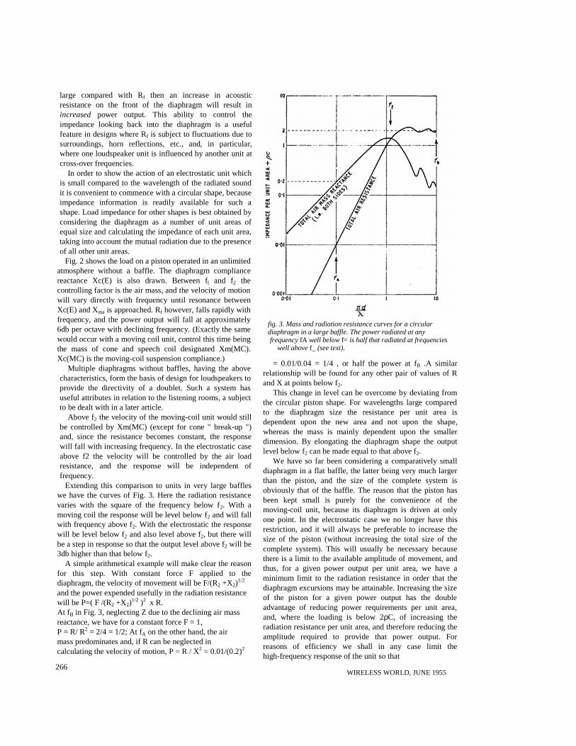
Fig. 2. Mass and radiation resistance loads on circulardiaphragm in free air. The normalized frequency stole is interms of the relationshipof diaphragm size to wavelength.
265
Wide Range Electrostatic Loudspeakers
large compared with Rf then an increase in acousticresistance on the front of the diaphragm will result inincreased power output. This ability to control theimpedance looking back into the diaphragm is a usefulfeature in designs where Rf is subject to fluctuations due tosurroundings, horn reflections, etc., and, in particular,where one loudspeaker unit is influenced by another unit atcross-over frequencies.
In order to show the action of an electrostatic unit whichis small compared to the wavelength of the radiated soundit is convenient to commence with a circular shape, becauseimpedance information is readily available for such ashape. Load impedance for other shapes is best obtained byconsidering the diaphragm as a number of unit areas ofequal size and calculating the impedance of each unit area,taking into account the mutual radiation due to the presenceof all other unit areas.
Fig. 2 shows the load on a piston operated in an unlimitedatmosphere without a baffle. The diaphragm compliancereactance Xc(E) is also drawn. Between fl and f2 thecontrolling factor is the air mass, and the velocity of motionwill vary directly with frequency until resonance betweenXc(E) and Xma is approached. Rf however, falls rapidly withfrequency, and the power output will fall at approximately6db per octave with declining frequency. (Exactly the samewould occur with a moving coil unit, control this time beingthe mass of cone and speech coil designated Xm(MC).Xc(MC) is the moving-coil suspension compliance.)
Multiple diaphragms without baffles, having the abovecharacteristics, form the basis of design for loudspeakers toprovide the directivity of a doublet. Such a system hasuseful attributes in relation to the listening rooms, a subjectto be dealt with in a later article.
Above f2 the velocity of the moving-coil unit would stillbe controlled by Xm(MC) (except for cone " break-up ")and, since the resistance becomes constant, the responsewill fall with increasing frequency. In the electrostatic caseabove f2 the velocity will be controlled by the air loadresistance, and the response will be independent offrequency.
Extending this comparison to units in very large baffleswe have the curves of Fig. 3. Here the radiation resistancevaries with the square of the frequency below f2. With amoving coil the response will be level below f2 and will fallwith frequency above f2. With the electrostatic the responsewill be level below f2 and also level above f2, but there willbe a step in response so that the output level above f2 will be3db higher than that below f2.
A simple arithmetical example will make clear the reasonfor this step. With constant force F applied to thediaphragm, the velocity of movement will be F/(R2 +X2)
1/2
and the power expended usefully in the radiation resistancewill be P=( F /(R2 +X2)
1/2 )2 x R.At f B in Fig. 3, neglecting Z due to the declining air massreactance, we have for a constant force F = 1,P = R/ R2 = 2/4 = 1/2; At fA on the other hand, the airmass predominates and, if R can be neglected incalculating the velocity of motion, P = R / X2 = 0.01/(0.2)2
WIRELESS WORLD, JUNE 1955266
fig. 3. Mass and radiation resistance curves for a circulardiaphragm in a large baffle. The power radiated at anyfrequencyfA well belowf= is half that radiated at frequencies
well abovef_ (see text).
= 0.01/0.04 = 1/4 , or half the power at fB .A similarrelationship will be found for any other pair of values of Rand X at points below f2.
This change in level can be overcome by deviating fromthe circular piston shape. For wavelengths large comparedto the diaphragm size the resistance per unit area isdependent upon the new area and not upon the shape,whereas the mass is mainly dependent upon the smallerdimension. By elongating the diaphragm shape the outputlevel below f2 can be made equal to that above f2.
We have so far been considering a comparatively smalldiaphragm in a flat baffle, the latter being very much largerthan the piston, and the size of the complete system isobviously that of the baffle. The reason that the piston hasbeen kept small is purely for the convenience of themoving-coil unit, because its diaphragm is driven at onlyone point. In the electrostatic case we no longer have thisrestriction, and it will always be preferable to increase thesize of the piston (without increasing the total size of thecomplete system). This will usually be necessary becausethere is a limit to the available amplitude of movement, andthus, for a given power output per unit area, we have aminimum limit to the radiation resistance in order that thediaphragm excursions may be attainable. Increasing the sizeof the piston for a given power output has the doubleadvantage of reducing power requirements per unit area,and, where the loading is below 2ρC, of increasing theradiation resistance per unit area, and therefore reducing theamplitude required to provide that power output. Forreasons of efficiency we shall in any case limit thehigh-frequency response of the unit so that
optimum design is obtained by increasing the area of thediaphragm to the point where the piston just begins tobecome directional at the frequency which we have chosenfor cross-over (set by the efficiency laid down in the designrequirements).
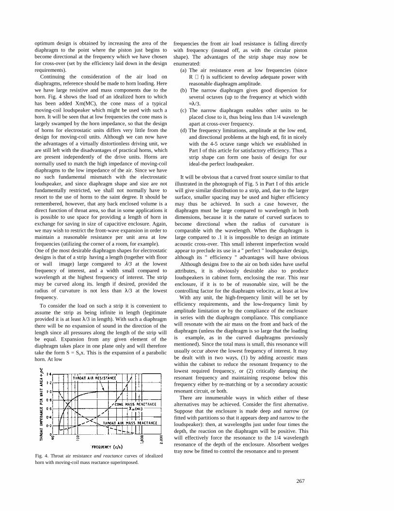
Continuing the consideration of the air load ondiaphragms, reference should be made to horn loading. Herewe have large resistive and mass components due to thehorn. Fig. 4 shows the load of an idealized horn to whichhas been added Xm(MC), the cone mass of a typicalmoving-coil loudspeaker which might be used with such ahorn. It will be seen that at low frequencies the cone mass islargely swamped by the horn impedance, so that the designof horns for electrostatic units differs very little from thedesign for moving-coil units. Although we can now havethe advantages of a virtually distortionless driving unit, weare still left with the disadvantages of practical horns, whichare present independently of the drive units. Horns arenormally used to match the high impedance of moving-coildiaphragms to the low impedance of the air. Since we haveno such fundamental mismatch with the electrostaticloudspeaker, and since diaphragm shape and size are notfundamentally restricted, we shall not normally have toresort to the use of horns to the saint degree. It should beremembered, however, that any back enclosed volume is adirect function of throat area, so that in some applications itis possible to use space for providing a length of horn inexchange for saving in size of capacitive enclosure. Again,we may wish to restrict the front-wave expansion in order tomaintain a reasonable resistance per unit area at lowfrequencies (utilizing the corner of a room, for example).One of the most desirable diaphragm shapes for electrostaticdesigns is that of a strip having a length (together with flooror wall image) large compared to λ/3 at the lowestfrequency of interest, and a width small compared towavelength at the highest frequency of interest. The stripmay be curved along its. length if desired, provided theradius of curvature is not less thanλ/3 at the lowestfrequency.
To consider the load on such a strip it is convenient toassume the strip as being infinite in length (legitimateprovided it is at leastλ/3 in length). With such a diaphragmthere will be no expansion of sound in the direction of thelength since all pressures along the length of the strip willbe equal. Expansion from any given element of thediaphragm takes place in one plane only and will thereforetake the form S = Sox. This is the expansion of a parabolichorn. At low
Fig. 4. Throat air resistanceand reactancecurves of idealizedhorn with moving-coil mass reactance superimposed.
frequencies the front air load resistance is falling directlywith frequency (instead off, as with the circular pistonshape). The advantages of the strip shape may now beenumerated:
(a) The air resistance even at low frequencies (sinceR ∝ f) is sufficient to develop adequate power withreasonable diaphragm amplitude.
(b) The narrow diaphragm gives good dispersion forseveral octaves (up to the frequency at which width≈λ/3.
(c) The narrow diaphragm enables other units to beplaced close to it, thus being less than 1/4 wavelengthapart at cross-over frequency.
(d) The frequency limitations, amplitude at the low end,and directional problems at the high end, fit in nicelywith the 4-5 octave range which we established inPart I of this article for satisfactory efficiency. Thus astrip shape can form one basis of design for ourideal-the perfect loudspeaker.
It will be obvious that a curved front source similar to thatillustrated in the photograph of Fig. 5 in Part I of this articlewill give similar distribution to a strip, and, due to the largersurface, smaller spacing may be used and higher efficiencymay thus be achieved. In such a case however, thediaphragm must be large compared to wavelength in bothdimensions, because it is the nature of curved surfaces tobecome directional when the radius of curvature iscomparable with the wavelength. When the diaphragm islarge compared to .1 it is impossible to design an intimateacoustic cross-over. This small inherent imperfection wouldappear to preclude its use in a " perfect " loudspeaker design,although its " efficiency " advantages will have obvious
Although designs free to the air on both sides have usefulattributes, it is obviously desirable also to produceloudspeakers in cabinet form, enclosing the rear. This rearenclosure, if it is to be of reasonable size, will be thecontrolling factor for the diaphragm velocity, at least at low
With any unit, the high-frequency limit will be set byefficiency requirements, and the low-frequency limit byamplitude limitation or by the compliance of the enclosurein series with the diaphragm compliance. This compliancewill resonate with the air mass on the front and back of thediaphragm (unless the diaphragm is so large that the loadingis example, as in the curved diaphragms previouslymentioned). Since the total mass is small, this resonance willusually occur above the lowest frequency of interest. It maybe dealt with in two ways, (1) by adding acoustic masswithin the cabinet to reduce the resonant frequency to thelowest required frequency, or (2) critically damping theresonant frequency and maintaining response below thisfrequency either by re-matching or by a secondary acousticresonant circuit, or both.
There are innumerable ways in which either of thesealternatives may be achieved. Consider the first alternative.Suppose that the enclosure is made deep and narrow (orfitted with partitions so that it appears deep and narrow to theloudspeaker): then, at wavelengths just under four times thedepth, the reaction on the diaphragm will be positive. Thiswill effectively force the resonance to the 1/4 wavelengthresonance of the depth of the enclosure. Absorbent wedgestray now be fitted to control the resonance and to present
267
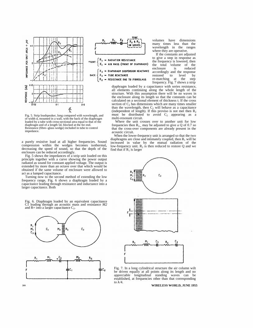
Fig. 5. Strip loudspeaker, long compared with wavelength, andof width d, mounted in a wall, with the back of the diaphragmloaded by a tube with cross-sectional area equal to that of thediaphragm and of a length 5d, blocked at the for end.Resistance (fibre--glass wedge) included in tube to controlimpedance.
a purely resistive load at all higher frequencies. Soundcompression within the wedges becomes isothermal,decreasing the speed of sound, so that the depth of theenclosure can be reduced accordingly.
Fig. 5 shows the impedances of a strip unit loaded on thisprinciple together with a curve showing the power outputradiated as sound for constant applied voltage. The output isextended by more than an octave over that which would beobtained if the same volume of enclosure were allowed toact as a lumped capacitance.
Turning now to the second method of extending the lowfrequency range, Fig. 6 shows a diaphragm loaded by acapacitance leading through resistance and inductance into alarger capacitance. Both
Fig. 6. Diaphragm loaded by an equivalent capacitanceC1 leading through an acoustic mass and resistanceM2and R= into a larger capacitance C2.
volumes have dimensionsmany times less than thewavelength in the rangeswhere they are operative.
If the constants are adjustedto give a step in response asthe frequency is lowered, thenthe total volume of theenclosure is reducedaccordingly and the responserestored to level byre-matching at the stepfrequency. Fig. 7 shows a strip
diaphragm loaded by a capacitance with series resistance,all elements continuing along the whole length of thestructure. With this assumption there will be no waves inthe enclosure along its length so that the constants can becalculated on a sectional element of thickness t. If the crosssection of C2 has dimensions which are many times smallerthan the wavelength, then C2 will behave as a capacitance(independent of length). If this proviso is not met then R2must be distributed to avoid C2 appearing as amulti-resonant circuit.
Where the unit crosses over to another unit for lowfrequencies then R2_ may be adjusted to give a Q of 0.7 sothat the cross-over components are already present in theacoustic circuit.
When the lower-frequency unit is arranged so that the twodiaphragms are close and intimately coupled, then R1 will beincreased in value by the mutual radiation of thelow-frequency unit. R2 is then reduced to restore Q and wefind that if R1 is larger
Fig. 7. In a long cylindrical structure the air column wiltbe driven equally at all points along its length and noappreciable longitudinal standing waves can beestablished, at frequencies other than that correspondingto λ/4.
WIRELESS WORLD, JUNE 1955ÿþý�
than R2 a useful self-compensating effect takes place.If the voltage applied to the low-frequency unit is reduced at
cross-over due to tolerance in its crossover componentsthen R1 is automatically reduced and the output of thehigher-frequency unit increases at cross-over. Atcross-overPout ∝ R1/(R1 + R2)
2
Where the enclosure of Fig. 7 is used for the unit coveringthe lowest part of the audio range, bass response may beextended by rematching or by introducing a secondaryresonant circuit and utilizing back radiation from thediaphragm. If an aperture is provided at one end of theenclosure, opening to the air, then, when the enclosurelength is ÿþýü wavelength, resonance will occur along itslength, and there will be radiation from the aperture. 3/4,5/'4 resonances, etc., will not arise, because the enclosure isexcited by a force distributed along its length. At frequen
cies above the�ü wavelength, the enclosure will behaveapproximately as a capacitance, as if the aperture were notpresent.
The next part of this article will deal with electrostaticunits as part of delay lines, and the application of variouscomplete designs, " built in," " boxed in " and " doublet " inrelation to the listening-room. Complete electrostaticloudspeakers can take several different forms, each of whichin terms of frequency response, distortion and sounddispersion can meet a specification virtually to perfection.When the listening-room and subjective factors areconsidered it becomes impossible to lay down a rigidspecification. To adopt a quotation " Each design is perfect,but some designs are more perfect than others "!
Acknowledgement. Fig. 2 is based on Fig 5. 9, p. 127 of"Acoustics" by Leo. L. Beranek (McGraw Hill).
(To be continued)
WIRELESS WORLD, JUNE1955 269
Wireless World July
"WIDE RANGE ELECTROSTATICLOU DSPEAKERS"
THE third instalment of thi s articles which beganin the May issue, is unavoidably held over. In themeantime it should he pointed out that in Part 2(June issue) the last sentence of the secondparagraph (p. 265) should read : " In practice thecompliance will be considerably less than theelectrical negative compliance… ",
Line 23, left-hand column, p. 266, should read"velocity of motion will vary inversely with fre-
ency"; and in line 2, right-hand column,p.267, "f2" should be " f 2 ".
By P. J. WALKER*
IN the first part of this article we showed that for a givensize, the apparent efficiency of an electrostatic unit may beincreased by reducing the bandwidth which that unit isrequired to cover. An obvious method of increasing theoverall efficiency of a complete electrostatic system,therefore, is to divide the system into a convenient numberof frequency bands and to feed them via crossovernetworks. Optimum design is obtained by increasing gapsand areas with decreasing frequency.
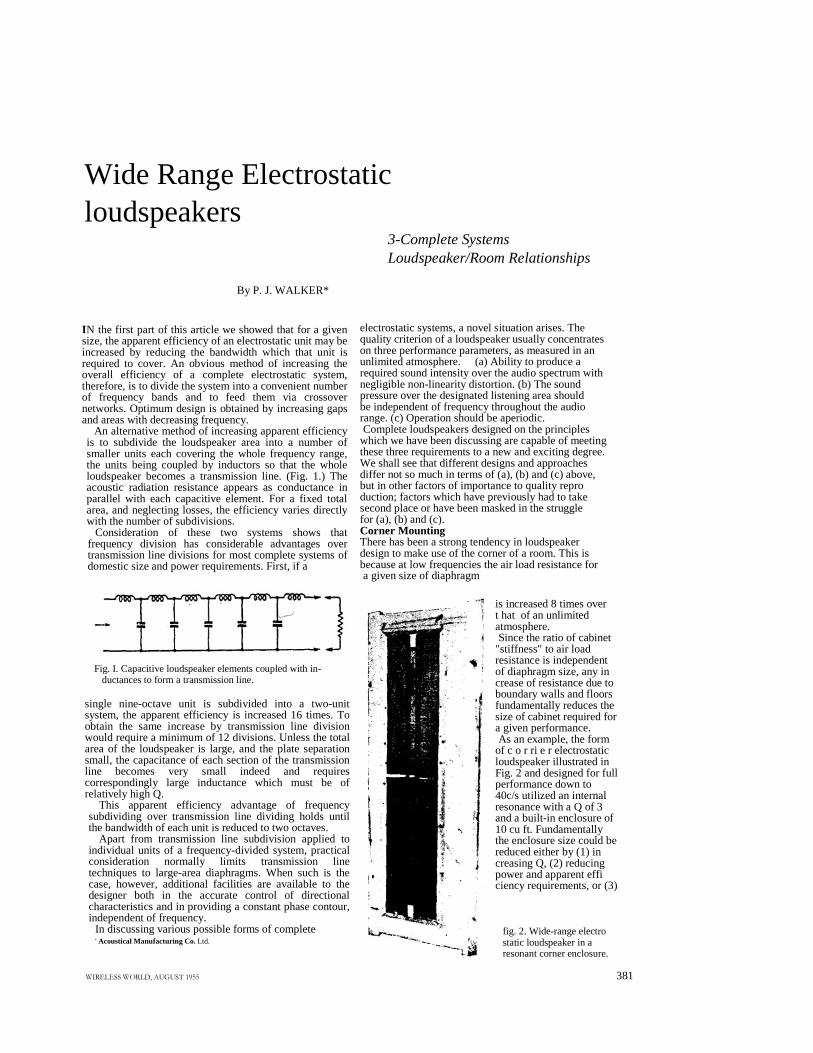
An alternative method of increasing apparent efficiencyis to subdivide the loudspeaker area into a number ofsmaller units each covering the whole frequency range,the units being coupled by inductors so that the wholeloudspeaker becomes a transmission line. (Fig. 1.) Theacoustic radiation resistance appears as conductance inparallel with each capacitive element. For a fixed totalarea, and neglecting losses, the efficiency varies directlywith the number of subdivisions.
Consideration of these two systems shows thatfrequency division has considerable advantages overtransmission line divisions for most complete systems ofdomestic size and power requirements. First, if a
Fig. I. Capacitive loudspeaker elements coupled with in-ductances to form a transmission line.
single nine-octave unit is subdivided into a two-unitsystem, the apparent efficiency is increased 16 times. Toobtain the same increase by transmission line divisionwould require a minimum of 12 divisions. Unless the totalarea of the loudspeaker is large, and the plate separationsmall, the capacitance of each section of the transmissionline becomes very small indeed and requirescorrespondingly large inductance which must be ofrelatively high Q.
This apparent efficiency advantage of frequencysubdividing over transmission line dividing holds untilthe bandwidth of each unit is reduced to two octaves.
Apart from transmission line subdivision applied toindividual units of a frequency-divided system, practicalconsideration normally limits transmission linetechniques to large-area diaphragms. When such is thecase, however, additional facilities are available to thedesigner both in the accurate control of directionalcharacteristics and in providing a constant phase contour,independent of frequency.
In discussing various possible forms of complete' Acoustical Manufacturing Co. Ltd.
ÿþýüûüúúùÿøýû÷öùõôóôúòùñðïïù
Wide Range Electrostaticloudspeakers
3-Complete SystemsLoudspeaker/Room Relationships
electrostatic systems, a novel situation arises. Thequality criterion of a loudspeaker usually concentrateson three performance parameters, as measured in anunlimited atmosphere. (a) Ability to produce arequired sound intensity over the audio spectrum withnegligible non-linearity distortion. (b) The soundpressure over the designated listening area shouldbe independent of frequency throughout the audiorange. (c) Operation should be aperiodic.Complete loudspeakers designed on the principles
which we have been discussing are capable of meetingthese three requirements to a new and exciting degree.We shall see that different designs and approachesdiffer not so much in terms of (a), (b) and (c) above,but in other factors of importance to quality reproduction; factors which have previously had to takesecond place or have been masked in the strugglefor (a), (b) and (c).Corner MountingThere has been a strong tendency in loudspeakerdesign to make use of the corner of a room. This isbecause at low frequencies the air load resistance fora given size of diaphragm
is increased 8 times overt hat of an unlimitedatmosphere.Since the ratio of cabinet
"stiffness" to air loadresistance is independentof diaphragm size, any increase of resistance due toboundary walls and floorsfundamentally reduces thesize of cabinet required fora given performance.As an example, the form
of c o r ri e r electrostaticloudspeaker illustrated inFig. 2 and designed for fullperformance down to40c/s utilized an internalresonance with a Q of 3and a built-in enclosure of10 cu ft. Fundamentallythe enclosure size could bereduced either by (1) increasing Q, (2) reducingpower and apparent efficiency requirements, or (3)
fig. 2. Wide-range electrostatic loudspeaker in aresonant corner enclosure.
381
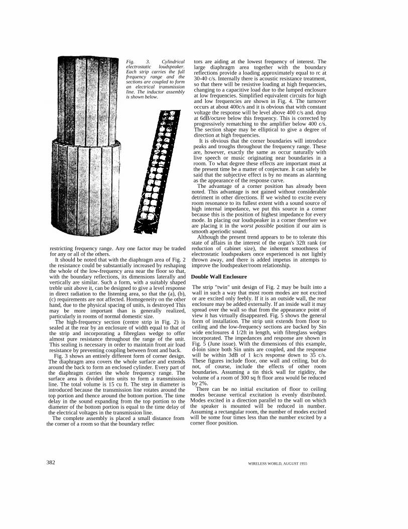
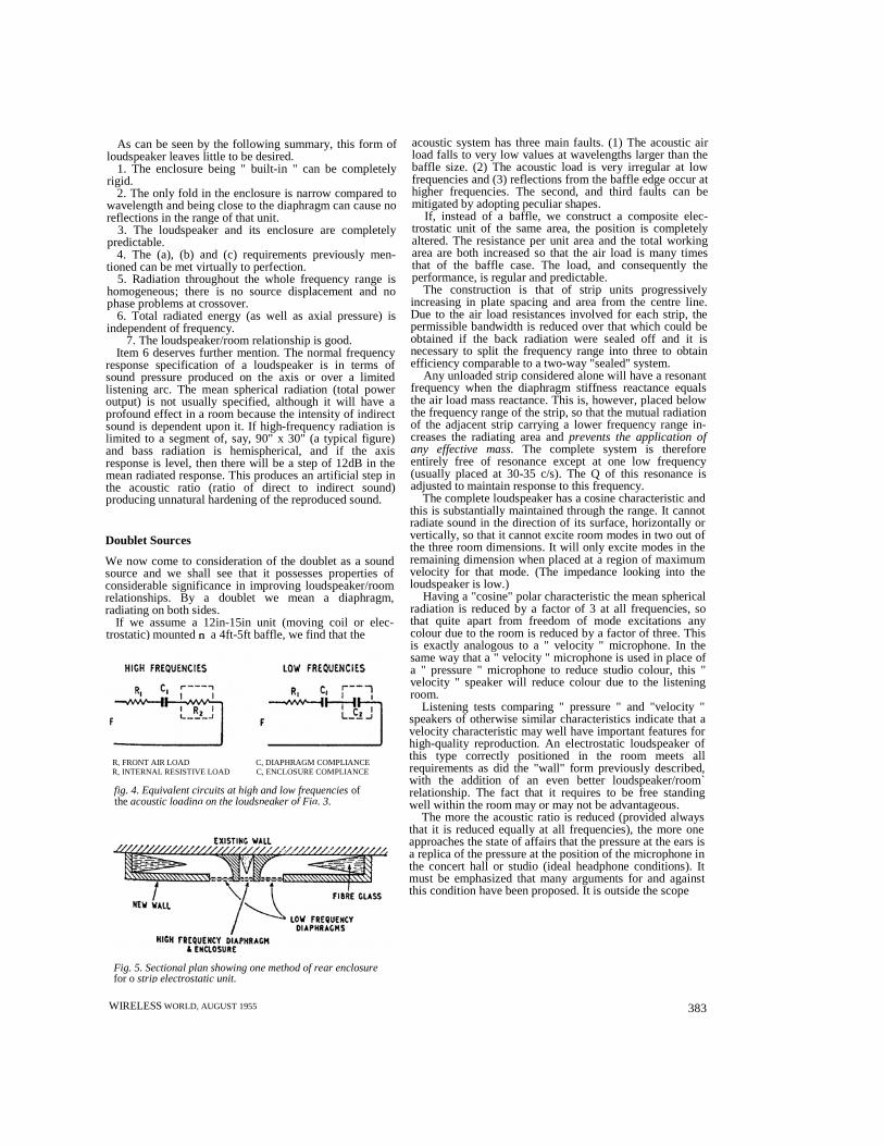
Fig. 3. Cylindricalelectrostatic loudspeaker.Each strip carries the fullfrequency range and thesections are coupled to forman electrical transmissionline. The inductor assemblyis shown below.
restricting frequency range. Any one factor may be tradedfor any or all of the others.
It should be noted that with the diaphragm area of Fig. 2the resistance could be substantially increased by reshapingthe whole of the low-frequency area near the floor so that,with the boundary reflections, its dimensions laterally andvertically are similar. Such a form, with a suitably shapedtreble unit above it, can be designed to give a level responsein direct radiation to the listening area, so that the (a), (b),(c) requirements are not affected. Homogeneity on the otherhand, due to the physical spacing of units, is destroyed Thismay be more important than is generally realized,particularly in rooms of normal domestic size.
The high-frequency section (centre strip in Fig. 2) issealed at the rear by an enclosure of width equal to that ofthe strip and incorporating a fibreglass wedge to offeralmost pure resistance throughout the range of the unit.This sealing is necessary in order to maintain front air loadresistance by preventing coupling between front and back.
Fig. 3 shows an entirely different form of corner design.The diaphragm area covers the whole surface and extendsaround the back to form an enclosed cylinder. Every part ofthe diaphragm carries the whole frequency range. Thesurface area is divided into units to form a transmissionline. The total volume is 15 cu ft. The step in diameter isintroduced because the transmission line rotates around thetop portion and thence around the bottom portion. The timedelay in the sound expanding from the top portion to thediameter of the bottom portion is equal to the time delay ofthe electrical voltages in the transmission line.
The complete assembly is placed a small distance fromthe corner of a room so that the boundary reflec
382
tors are aiding at the lowest frequency of interest. Thelarge diaphragm area together with the boundaryreflections provide a loading approximately equal to rc at30-40 c/s. Internally there is acoustic resistance treatment,so that there will be resistive loading at high frequencies,changing to a capacitive load due to the lumped enclosureat low frequencies. Simplified equivalent circuits for highand low frequencies are shown in Fig. 4. The turnoveroccurs at about 400c/s and it is obvious that with constantvoltage the response will be level above 400 c/s and. dropat 6dB/octave below this frequency. This is corrected byprogressively rematching to the amplifier below 400 c/s.The section shape may be elliptical to give a degree ofdirection at high frequencies.
It is obvious that the corner boundaries will introducepeaks and troughs throughout the frequency range. Theseare, however, exactly the same as occur naturally withlive speech or music originating near boundaries in aroom. To what degree these effects are important must atthe present time be a matter of conjecture. It can safely besaid that the subjective effect is by no means as alarmingas the appearance of the response curve.
The advantage of a corner position has already beennoted. This advantage is not gained without considerabledetriment in other directions. If we wished to excite everyroom resonance to its fullest extent with a sound source ofhigh internal impedance, we put this source in a cornerbecause this is the position of highest impedance for everymode. In placing our loudspeaker in a corner therefore weare placing it in theworst possibleposition if our aim issmooth aperiodic sound.
Although the present trend appears to be to tolerate thisstate of affairs in the interest of the organ's 32ft rank (orreduction of cabinet size), the inherent smoothness ofelectrostatic loudspeakers once experienced is not lightlythrown away, and there is added impetus in attempts toimprove the loudspeaker/room relationship.
Double Wall Enclosure
The strip "twin" unit design of Fig. 2 may be built into awall in such a way that most room modes are not excitedor are excited only feebly. If it is an outside wall, the rearenclosure may be added externally. If an inside wall it mayspread over the wall so that from the appearance point ofview it has virtually disappeared. Fig. 5 shows the generalform of installation. The strip unit extends from floor toceiling and the low-frequency sections are backed by Sinwide enclosures 4 1/2ft in length, with fibreglass wedgesincorporated. The impedances and response are shown inFig. 5 (June issue). With the dimensions of this example,d-loin since both Sin units are coupled, and the responsewill be within 3dB of 1 kc/s response down to 35 c/s.These figures include floor, one wall and ceiling, but donot, of course, include the effects of other roomboundaries. Assuming a tin thick wall for rigidity, thevolume of a room of 300 sq ft floor area would be reducedby 2%.
There can be no initial excitation of floor to ceilingmodes because vertical excitation is evenly distributed.Modes excited in a direction parallel to the wall on whichthe speaker is mounted will be reduced in number.Assuming a rectangular room, the number of modes excitedwill be some four times less than the number excited by acorner floor position.
WIRELESS WORLD, AUGUST 1955
As can be seen by the following summary, this form ofloudspeaker leaves little to be desired.
1. The enclosure being " built-in " can be completelyrigid.
2. The only fold in the enclosure is narrow compared towavelength and being close to the diaphragm can cause noreflections in the range of that unit.
3. The loudspeaker and its enclosure are completelypredictable.
4. The (a), (b) and (c) requirements previously men-tioned can be met virtually to perfection.
5. Radiation throughout the whole frequency range ishomogeneous; there is no source displacement and nophase problems at crossover.
6. Total radiated energy (as well as axial pressure) isindependent of frequency.
7. The loudspeaker/room relationship is good.Item 6 deserves further mention. The normal frequency
response specification of a loudspeaker is in terms ofsound pressure produced on the axis or over a limitedlistening arc. The mean spherical radiation (total poweroutput) is not usually specified, although it will have aprofound effect in a room because the intensity of indirectsound is dependent upon it. If high-frequency radiation islimited to a segment of, say, 90" x 30" (a typical figure)and bass radiation is hemispherical, and if the axisresponse is level, then there will be a step of 12dB in themean radiated response. This produces an artificial step inthe acoustic ratio (ratio of direct to indirect sound)producing unnatural hardening of the reproduced sound.
Doublet Sources
We now come to consideration of the doublet as a soundsource and we shall see that it possesses properties ofconsiderable significance in improving loudspeaker/roomrelationships. By a doublet we mean a diaphragm,radiating on both sides.
If we assume a 12in-15in unit (moving coil or elec-trostatic) mounted��ù a 4ft-5ft baffle, we find that the
R, FRONT AIR LOAD C, DIAPHRAGM COMPLIANCER, INTERNAL RESISTIVE LOAD C, ENCLOSURE COMPLIANCE
fig. 4. Equivalent circuits at high and low frequenciesoftheacoustic loading on the loudspeaker of Fig. 3.
Fig. 5. Sectional plan showing one method of rear enclosurefor o strip electrostatic unit.
WIRELESSWORLD, AUGUST 1955
acoustic system has three main faults. (1) The acoustic airload falls to very low values at wavelengths larger than thebaffle size. (2) The acoustic load is very irregular at lowfrequencies and (3) reflections from the baffle edge occur athigher frequencies. The second, and third faults can bemitigated by adopting peculiar shapes.
If, instead of a baffle, we construct a composite elec-trostatic unit of the same area, the position is completelyaltered. The resistance per unit area and the total workingarea are both increased so that the air load is many timesthat of the baffle case. The load, and consequently theperformance, is regular and predictable.
The construction is that of strip units progressivelyincreasing in plate spacing and area from the centre line.Due to the air load resistances involved for each strip, thepermissible bandwidth is reduced over that which could beobtained if the back radiation were sealed off and it isnecessary to split the frequency range into three to obtainefficiency comparable to a two-way "sealed" system.
Any unloaded strip considered alone will have a resonantfrequency when the diaphragm stiffness reactance equalsthe air load mass reactance. This is, however, placed belowthe frequency range of the strip, so that the mutual radiationof the adjacent strip carrying a lower frequency range in-creases the radiating area andprevents the application ofany effective mass.The complete system is thereforeentirely free of resonance except at one low frequency(usually placed at 30-35 c/s). The Q of this resonance isadjusted to maintain response to this frequency.
The complete loudspeaker has a cosine characteristic andthis is substantially maintained through the range. It cannotradiate sound in the direction of its surface, horizontally orvertically, so that it cannot excite room modes in two out ofthe three room dimensions. It will only excite modes in theremaining dimension when placed at a region of maximumvelocity for that mode. (The impedance looking into theloudspeaker is low.)
Having a "cosine" polar characteristic the mean sphericalradiation is reduced by a factor of 3 at all frequencies, sothat quite apart from freedom of mode excitations anycolour due to the room is reduced by a factor of three. Thisis exactly analogous to a " velocity " microphone. In thesame way that a " velocity " microphone is used in place ofa " pressure " microphone to reduce studio colour, this "velocity " speaker will reduce colour due to the listeningroom.
Listening tests comparing " pressure " and "velocity "speakers of otherwise similar characteristics indicate that avelocity characteristic may well have important features forhigh-quality reproduction. An electrostatic loudspeaker ofthis type correctly positioned in the room meets allrequirements as did the "wall" form previously described,with the addition of an even better loudspeaker/room`relationship. The fact that it requires to be free standingwell within the room may or may not be advantageous.
The more the acoustic ratio is reduced (provided alwaysthat it is reduced equally at all frequencies), the more oneapproaches the state of affairs that the pressure at the ears isa replica of the pressure at the position of the microphone inthe concert hall or studio (ideal headphone conditions). Itmust be emphasized that many arguments for and againstthis condition have been proposed. It is outside the scope
383
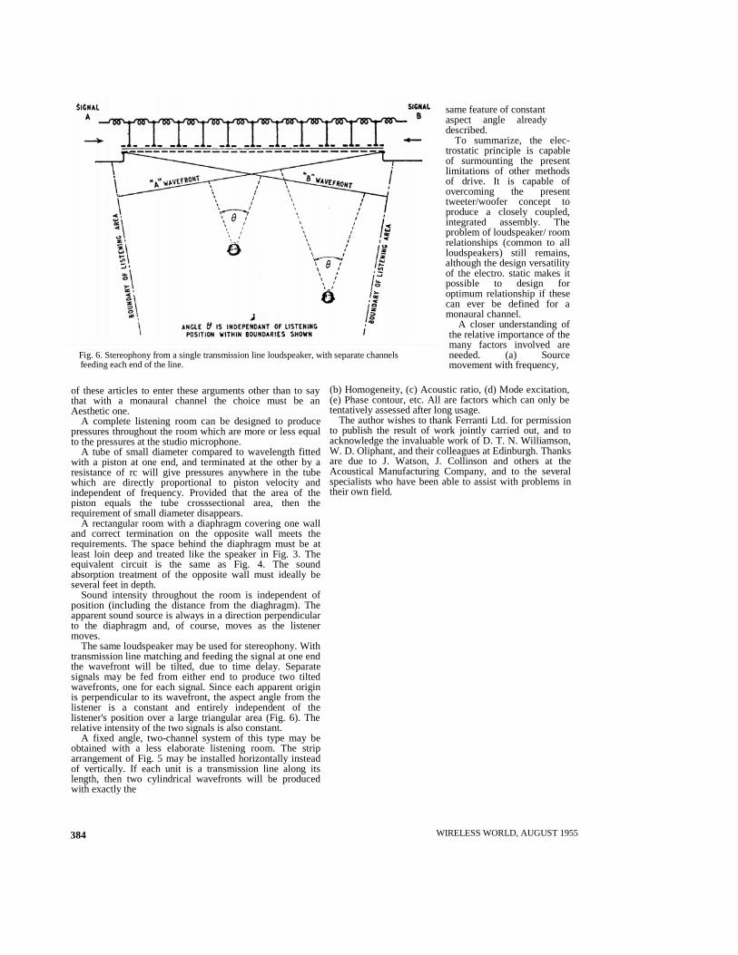
Fig. 6. Stereophony from a single transmission lineloudspeaker, with separate channelsfeeding each end of the line.
of these articles to enter these arguments other than to saythat with a monaural channel the choice must be anAesthetic one.
A complete listening room can be designed to producepressures throughout the room which are more or less equalto the pressures at the studio microphone.
A tube of small diameter compared to wavelength fittedwith a piston at one end, and terminated at the other by aresistance of rc will give pressures anywhere in the tubewhich are directly proportional to piston velocity andindependent of frequency. Provided that the area of thepiston equals the tube crosssectional area, then therequirement of small diameter disappears.
A rectangular room with a diaphragm covering one walland correct termination on the opposite wall meets therequirements. The space behind the diaphragm must be atleast loin deep and treated like the speaker in Fig. 3. Theequivalent circuit is the same as Fig. 4. The soundabsorption treatment of the opposite wall must ideally beseveral feet in depth.
Sound intensity throughout the room is independent ofposition (including the distance from the diaghragm). Theapparent sound source is always in a direction perpendicularto the diaphragm and, of course, moves as the listenermoves.
The same loudspeaker may be used for stereophony. Withtransmission line matching and feeding the signal at one endthe wavefront will be tilted, due to time delay. Separatesignals may be fed from either end to produce two tiltedwavefronts, one for each signal. Since each apparent originis perpendicular to its wavefront, the aspect angle from thelistener is a constant and entirely independent of thelistener's position over a large triangular area (Fig. 6). Therelative intensity of the two signals is also constant.
A fixed angle, two-channel system of this type may beobtained with a less elaborate listening room. The striparrangement of Fig. 5 may be installed horizontally insteadof vertically. If each unit is a transmission line along itslength, then two cylindrical wavefronts will be producedwith exactly the
384
same feature of constantaspect angle alreadydescribed.
To summarize, the elec-trostatic principle is capableof surmounting the presentlimitations of other methodsof drive. It is capable ofovercoming the presenttweeter/woofer concept toproduce a closely coupled,integrated assembly. Theproblem of loudspeaker/ roomrelationships (common to allloudspeakers) still remains,although the design versatilityof the electro. static makes itpossible to design foroptimum relationship if thesecan ever be defined for amonaural channel.
A closer understanding ofthe relative importance of themany factors involved areneeded. (a) Sourcemovement with frequency,
(b) Homogeneity, (c) Acoustic ratio, (d) Mode excitation,(e) Phase contour, etc. All are factors which can only betentatively assessed after long usage.
The author wishes to thank Ferranti Ltd. for permissionto publish the result of work jointly carried out, and toacknowledge the invaluable work of D. T. N. Williamson,W. D. Oliphant, and their colleagues at Edinburgh. Thanksare due to J. Watson, J. Collinson and others at theAcoustical Manufacturing Company, and to the severalspecialists who have been able to assist with problems intheir own field.
WIRELESS WORLD, AUGUST 1955