Embed Size (px)
Citation preview

WIDE
CIRULATION DOCUMENT DESPATCH ADVICE
TECHNICAL COMMITTEE: LITD 08 Ref: Date LITD 08/T- 107 05/06/2017
ADDRESSED TO: 1. All Members of Electronic Measuring Instruments, Systems and Accessories Sectional Committee, LITD 08 2. All Principal Members of Electronics and Information Technology Division Council
(LITDC)
3. All others interested
Dear Sir(s),
Please find enclosed the draft Indian Standard:
1 LITD 08 (10740) WEIGH – IN – MOTION SYSTEM FOR ROAD VEHICLES -
SPECIFICATION
Kindly examine the draft Indian standard and forward your comments stating any difficulties which you
are likely to experience in your business or profession, if this is finally adopted as National Standard.
Last Date for comments: 05.08.2017
Comments, if any, may please made in the format indicated and mailed to the undersigned at e-mail id
Thanking you,
Yours faithfully,
(Reena Garg)
Sc.`E’ &Head (Electronics & IT)
E-mail: [email protected]
Telefax: 011-23237093
BUREAU OF INDIAN STANDARDS TeleFax +91 11 2323 7093
Phones 2323 0131
2323 3375 Extn 4442
ManakBhavan, 9 Bahadur Shah Zafar Marg New Delhi 110002
Website : www.bis.org.in
Email : [email protected]

वयपाक परिचालन मसौदा परलख परकषण सजञापन
तकनीकी सममतत :एलआईटीडी 08 सदरभ ददनाक
एलआईटीडी 08/टी-107 05/06/2017
पान वाल का नाम: 1)इलकटरॉनिक मापि उपकरण, परणाललयाा और उपकरण विषय सलमनि एलआईटीडी ,80
2)इलकटरॉनिकी एि सचिा पर दय गिकी विभाि पररषद क परधाि सदसय
3)अनय रगच रखि िाल
मह दय(यो)
कपया सलगि परलख का अिल कि कर: 1 एलआईटीडी 08 (10740) सडक िाहिो क ललए िजि – िनिपरणाली – विनिदश
कपया इस मस द का अिल कि कर और अपिी सममनियाा, यह बिाि हए कक यदद यह भारिीय मािक परकालशि हो ि अमल करि म आप क वयिसाय म कटया कदििाईयाा आ सकिी ह, भज । सममनियाा भजि की अनिम निगि : 05.08.2017
यदद क ई सममनियाा हो ि , कपया अध हसिाकषरी क ई-मल आईडी [email protected] पर सलगि फ मट म भज द ।
धनयिाद, भिदीया,
(रीिा ििग)
ि० ‘ई’एि परमख (इलकटरॉनिकी ि आई टी) ई मल:[email protected]
टमलफकस: 01123237093
BUREAU OF INDIAN STANDARDS TeleFax +91 11 2323 7093
Phones 2323 0131
2323 3375 Extn 4442
ManakBhavan, 9 Bahadur Shah Zafar Marg New Delhi 110002
Website : www.bis.org.in
Email : [email protected]

FORMAT FOR SENDING COMMENTS ON BIS DOCUMENTS
(Please use A4 size sheet of paper only and type within fields indicated. Comments on each
clauses/sub-clauses/table/fig. etc be started on a fresh box. Information in Column 4 should
include reasons for the comments and suggestions for modified wording of the clauses when the
existing text is found not acceptable. Adherence to this format facilitates Secretariat’s work)
Doc. No.: LITD 08 (10740)
TITLE: WEIGH - IN - MOTION SYSTEM FOR ROAD VEHICLES —
SPECIFICATION
LAST DATE OF COMMENTS: _05 Aug 2017
NAME OF THE COMMENTATOR/ORGANIZATION: _________________________
Sl.
No.
Clause/Sub
clause/
Para/table/fig.
No.
commented
Commentator/
Organization/
Abbreviation
Type of
Comments
(General/Editorial/
Technical)
Justification Proposed
change

Doc: LITD 08 (10740) IS XXXXX: 2017
i
BUREAU OF INDIAN STANDARDS
DRAFT FOR COMMENTS ONLY
(Not to be reproduced without the permission of BIS or used as a STANDARD)
Draft Indian Standard WEIGH - IN - MOTION SYSTEM FOR ROAD VEHICLES — SPECIFICATION
Last date of receipt of comments: 05 Aug 2017
_____________________________________________________________________________________
Electronics Measuring Instruments, Systems and Accessories Sectional Committee, LITD 08
FOREWORD
This Draft Indian Standard may be adopted by the Bureau of Indian Standards after the draft finalized by the electronics measuring instruments, systems and accessories sectional committee had been approved by the Electronics and Information Technology Division Council.(formal clauses to be added later)
In line with the Government policy of introduction of modern and innovative technology to find solution for the highway sector, Ministry of road and highways (MoRTH) has taken initiative for nationwide traffic survey and overloaded control on Toll Plaza with Weigh – In – Motion System (WIM). In this framework it was felt essential to have a WIM system which can be installed on Highway and used for a) infrastructural and statistical purpose- Economic and technical study of freight transport, detailed analysis of traffic for design and maintenance of road and bridges, classification of vehicles, and collecting statistical data, b) Aiding enforcement- screening of overloaded vehicles and c) enforcement- weight, both for both low and high speed vehicle. Accordingly this standard has been formulated based on the draft specifications prepared by MoRTH. MoRTH has prepared the draft specifications based on the following publications: OIML R 134-1:2006: International Recommendation for Automatic instruments for weighing road vehicles in motion and measuring axle loads, Part-1: Metrological and technical requirements – Tests; published by the Organisation Internationale De Métrolie Légale (OIML). COST 323 “Weigh-in-Motion of Road Vehicles” Final Report (1993-1998) Appendix-1: European WIM Specification. ASTM E 1318-09: Standard Specification for Highway Weigh-In-Motion (WIM) Systems with User Requirements and Test Methods; published by American Society for Testing and Materials (ASTM International). Draft European Standard pr EN (NN nnnnn) Version 2010/1: Weigh-in-Motion of Road Vehicles developed by the Federation of European Highway Research Laboratories WIM initiative (FiWi) and available as draft standard DIN 8113. For the purpose of deciding whether a particular requirement of this standard is complied with, the final value, observed or calculated expressing the result of a test or analysis, shall be rounded off in accordance with IS 2: 1960 ‘Rules for rounding off Numerical values (revised).

Doc: LITD 08 (10740) IS XXXXX: 2017
ii
Contents 0 Introduction ............................................................................................................................................... vi
1 SCOPE ......................................................................................................................................................... 1
2 REFERENCES ........................................................................................................................................... 1
3 TERMINOLOGY ....................................................................................................................................... 1
3.1 General Definitions .................................................................................................................................. 1
3.2 Construction ............................................................................................................................................. 3
3.3 Metrological Characteristics .................................................................................................................. 7
3.4 Indications and Errors .......................................................................................................................... 12
3.5 Influences and Reference Conditions .................................................................................................. 15
3.6 Tests ........................................................................................................................................................ 16
3.7 Vehicles ................................................................................................................................................... 16
3.8 Statistics .................................................................................................................................................. 17
3.9 Data ......................................................................................................................................................... 18
3.10 Abbreviations and symbols ................................................................................................................. 18
4 FUNCTIONAL TYPE CLASSIFICATION .......................................................................................... 19
4.1 General Type .......................................................................................................................................... 19
4.2 Special Type ........................................................................................................................................... 22
4.3 User Input ............................................................................................................................................... 22
4.4 Manufacturer/Vendor Input ................................................................................................................ 22
5 GENERAL REQUIREMENTS .............................................................................................................. 23
5.1 Suitability for Use .................................................................................................................................. 23
5.2 Security of Operation ............................................................................................................................ 23
5.3 Zero-Setting Devices .............................................................................................................................. 24
5.4 Use as an Integral Control Instrument ................................................................................................ 24
5.5 Vehicle Control Device .......................................................................................................................... 25
5.6 Indicating, Printing, Data Transmission and Data Storage Devices ................................................ 28
5.7 Data Content, Structure and Format................................................................................................... 31
5.8 Software .................................................................................................................................................. 40
5.9 Installation Environment ...................................................................................................................... 41
5.10 Securing Of Components, Interfaces and Preset Controls .............................................................. 43
5.11 Auxiliary Devices ................................................................................................................................. 44
5.12 Markings .............................................................................................................................................. 44
5.13 Verification Marks .............................................................................................................................. 46
5.13.3 BIS Certification Marking ............................................................................................................... 46

Doc: LITD 08 (10740) IS XXXXX: 2017
iii
6 PERFORMANCE REQUIREMENTS ................................................................................................... 46
6.1 Applicability ........................................................................................................................................... 46
6.2 Reference Values .................................................................................................................................... 47
6.3 Performance Criteria for Items Other Than Wheel/Axle Loads Or Vehicle Mass ........................ 48
6.4 Accuracy Criteria for Wheel Loads, Axle Loads And Vehicle Mass ................................................ 49
6.5 Statistical Accuracy Classes .................................................................................................................. 50
6.6 Performance Tests ................................................................................................................................. 59
7 METROLOGICAL REQUIREMENTS ................................................................................................ 59
7.1 Applicability ........................................................................................................................................... 59
7.2 Metrological Verification Class ............................................................................................................ 59
7.3 Metrological Accuracy Class ................................................................................................................ 61
7.4 Scale interval .......................................................................................................................................... 63
7.5 Limits of Error (For Vehicle Mass, Axle Load, Wheel Load) ........................................................... 65
7.6 Installation and testing of WIM systems ............................................................................................. 68
7.7 Agreement between Indicating and Printing Devices ........................................................................ 68
7.8 Influence Quantities .............................................................................................................................. 68
7.9 Scale Interval for Stationery Load ....................................................................................................... 70
7.10 Operating Speed .................................................................................................................................. 70
8 REQUIREMENTS FOR ELECTRONIC INSTRUMENTS................................................................ 70
8.1 General Requirements .......................................................................................................................... 70
8.2 Application ............................................................................................................................................. 71
8.3 Functional Requirements ...................................................................................................................... 71
9 METROLOGICAL CONTROLS ........................................................................................................... 73
9.1 Model (Type) Approval ......................................................................................................................... 73
9.2 Initial Verification ................................................................................................................................. 79
9.3 Subsequent Metrological Control ........................................................................................................ 81
10 TEST METHODS .................................................................................................................................. 81
10.1 Test Procedures ................................................................................................................................... 81
10.2 Control Instrument ............................................................................................................................. 82
10.3 Static Weighing Test for Integral Control Instruments .................................................................. 84
10.4 Verification Standards ........................................................................................................................ 84
10.5 Reference Vehicles ............................................................................................................................... 85
10.6 Reference Impact Force Generator ................................................................................................... 86
10.7 Test Plans ............................................................................................................................................. 86
10.7.1 Standard Test Plans ......................................................................................................................... 87
10.8 Number of In-Motion Tests for Weighing Performance ................................................................. 94

Doc: LITD 08 (10740) IS XXXXX: 2017
iv
10.9 Conventional True Value of the Reference Vehicle Mass ............................................................... 94
10.10 Conventional True Value of the Static Reference Single-Axle Load ............................................ 94
10.11 Indicated Mass of the Vehicle ........................................................................................................... 94
10.12 Indicated Single-Axle Load, Axle-Group Load, Axle Load (Axle Of A Group), Individual Axle Load .................................................................................................................................................... 94
10.13 Indicated Wheel Load ....................................................................................................................... 94
10.14 Mean Single-Axle Load, Mean Axle-Group Load and Mean Axle Load (Axle Of A Group), Individual Axle Load ........................................................................................................................ 95
10.15 Mean Wheel Load .............................................................................................................................. 95
10.16 Corrected Mean of the Single-Axle Load, Axle-Group Load, Axle Load (Axle of A Group) .... 95
10.17 Corrected Mean of the Wheel Load ................................................................................................. 95
10.18 Indicated Operating Speed ............................................................................................................... 95
10.19 Indicated Acceleration ...................................................................................................................... 96
10.20 Indicated Impact Load ...................................................................................................................... 96
10.21 Examination and Tests of Electronic Instruments ......................................................................... 96
Annex A ........................................................................................................................................................ 98
(Normative) ................................................................................................................................................... 98
Test Procedures for Weigh-In-Motion Systems for Road Vehicles ....................................................... 98
A.1 Examination for Type Approval ......................................................................................................... 98
A.2 Examination for Initial Verification ................................................................................................... 98
A.3 General Test Conditions ...................................................................................................................... 99
A.4 Test Program ....................................................................................................................................... 101
A.5 Performance Test During Type Evaluation ..................................................................................... 102
A.6 Additional Functionality .................................................................................................................... 105
A.7 Influence Factor and Disturbance Tests ........................................................................................... 106
A.8 Span Stability Test .............................................................................................................................. 130
A.9 Procedure for In-Motion Tests .......................................................................................................... 133
A.10 Procedure for Impact Force Tests .................................................................................................. 149
A.11 Procedure for Assessment of Accuracy Class ................................................................................ 149
Annex B ....................................................................................................................................................... 156
(Normative) ................................................................................................................................................. 156
(Mandatory for application in legal domain, informative in other applications) ................................ 156
Practical Instructions for the Installation Of Weigh-In-Motion Systems For Road Vehicles ........... 156
B.1 Installation and Operation ................................................................................................................. 156
B.2 Weigh-In-Motion Site (WIM Site)..................................................................................................... 156
B.3 WIM Site Characteristics ................................................................................................................... 156
Annex C ...................................................................................................................................................... 161

Doc: LITD 08 (10740) IS XXXXX: 2017
v
(Informative) ............................................................................................................................................... 161
General Guidelines for the Installation and Operation of Weigh-In-Motion Systems ...................... 161
C.1 Choice of Site for Pavement WIM (Not For Bridge WIM) ............................................................ 161
C.2 Particular Requirements of Bridge WIM System ......................................................................... 161
C.3 Particular Requirements of Type 1 WIM System ........................................................................... 162
C.3.1 Apron Characteristics ..................................................................................................................... 162
C.3.2 Apron Compliance Checks ............................................................................................................. 162
C.4. Operational Requirements ................................................................................................................ 163
Annex D ...................................................................................................................................................... 164
(Informative) ............................................................................................................................................... 164
General Guidelines for the Calibration of Weigh-In-Motion Systems ................................................ 164
D.1 General ................................................................................................................................................ 164
D.2 Reference Values ................................................................................................................................. 164
D.3 Calibration Checks ............................................................................................................................. 164
D.4 Calibration Methods ........................................................................................................................... 164
Annex E ...................................................................................................................................................... 168
(Informative) ............................................................................................................................................... 168
Procedure for Calculation of Equivalent Standard Axle Load ............................................................. 168
E.1 General ................................................................................................................................................. 168
E.2 Methodology Based On IRC:37-2012 ................................................................................................ 168
ANNEX-F ................................................................................................................................................... 171
(Normative) ................................................................................................................................................. 171
(Clause 2) List of References ..................................................................................................................... 171
Bibliography ............................................................................................................................................... 173

Doc: LITD 08 (10740) IS XXXXX: 2017
vi
0 Introduction
0.1 This Standard applies to WIM systems a) Which uses WIM instrument of either fixed type or portable type, installed in controlled weighing area (see.3.2.1), either on a road pavement or on a road bridge, either at a place where the vehicle speed is controlled or on a stretch of the main highway where the vehicle speed is not controlled; b) which are used for determining and indicating load related data items like vehicle mass1, single-axle loads2, the axle-group loads3, axle load of axles-of-a-group4, the wheel loads5, when the vehicles are weighed in motion6 and additionally, other vehicle characteristics like centre-to-centre distance between axles, vehicle class, wheelbase, vehicle speed, acceleration, etc., c) Which are to be used for enforcement purposes either under the supervision of personnel or in fully automatic mode;
0.2 This Standard applies to WIM systems which are used in the following domain: 0.2.1 Statistics – Economical and technical studies of freight transport, general traffic evaluation on roads and bridges, collecting statistical traffic data, etc. 0.2.2 Infrastructure – Detailed analysis of traffic, design and maintenance of roads and bridges, count and classification of vehicles. 0.2.3 Pre-selection/screening – Selection of vehicles from the traffic stream on the main highway or a diversion lane, for enforcement of legally specified limits on vehicle mass, and if applicable, on axle loads, vehicle speed, and/or in special cases acceleration. 0.2.4 Legal – Enforcement, including direct enforcement, of legally specified limits on vehicle mass, and if applicable on axle loads, wheel loads, vehicle speed and/or in special cases acceleration; consistent with legal provision. 1 Total mass of the vehicle combination including all connected components (see 3.1.5). 2 Fraction of the vehicle mass that is supported via the axle on the load receptor at the time of weighing (see 3.3.1.8). 3 In determining the single-axle load, and if required the axle-group load, and if required the axle load of axle-of-a-group, conditions in 7.6 and, if appropriate the requirements of national regulation should be taken into account. For the purposes of this specification, if no criteria for defining various axle-groups have been specified, axle load of axle of a group shall be considered as single-axle loads. 4 Axle load which is part of an axle-group load; sum of all wheel loads in an axle which is part of an axle-group. In case of conventional steel leaf spring suspension, the reliability of measurements should be considered before putting determination of axle load of axle-of-a-group as a system requirement. In this Specification, accuracy criteria for wheel loads are reasonable expected values but not mandatory unless specifically mentioned to be so (see 6.4.4, see 9.1.3.2.2.2.III). 5 Sum of the tyre loads on all tyres included in the wheel assembly on one end of an axle (see 3.3.1.18). A wheel assembly can have single or dual tyres. In this Specification, accuracy criteria for wheel loads are reasonable expected values but not mandatory unless specifically mentioned to be so ( See.6.4.5, See .9.1.3.2.2.2.IV) 6 “Weighed in motion” means that the mass of the vehicle was determined while the vehicle was crossing over the load receptor of the WIM system

1
Draft Indian standard for WEIGH – IN -- MOTION SYSTEM FOR ROAD VEHICLES —
SPECIFICATION 1 SCOPE
1.1 This Indian standard covers all aspects of WIM system which includes functional type classification, technical requirements, metrological requirements, other performance requirements, test methods and tests procedures for type (model) approval, on site acceptance test, verification and accuracy assessment incorporating both statistical principles and metrological principles, and including simulation tests in laboratory, wherever possible. 1.2 This Indian standard is applicable to Low speed vehicles of limited speed of ≤ 10 or 15 km/h and High speed vehicles of speed ≤ 130 Km/h. 1.3 This Specification does not apply to WIM systems that are installed on-board vehicles to measure axle load. 2 REFERENCES The standards listed in Annex F are necessary adjuncts to this standard. 3 TERMINOLOGY For the purpose of this standard, the following definition(s) shall apply.
3.1 General Definitions
3.1.1 Weighing Instrument
Measuring instrument used to determine the mass of a body by using the action of gravity on the body. (Note: In this Specification “mass” (or “weight value”) is preferably used in the sense of
“conventional mass” or “conventional value of the result of weighing in air “whereas “weight” is
preferably used for an embodiment (= material measure) of mass that is regulated in regard to its
physical and metrological characteristics)
The instrument may also be used to determine other mass-related quantities, magnitudes, parameters or characteristics (e.g. axle load, axle-group load, wheel load of a vehicle). The instrument may be scales which are able to weigh standard masses statically, or sensors which are able to measure loads not statically but dynamically. According to its method of operation, a weighing instrument is classified as an automatic or non- automatic instrument.

Doc: LITD 08 (10740) IS XXXXX: 2017
2
3.1.2 Automatic Weighing Instrument Instrument that weighs without the intervention of an operator and that follows a predetermined program of automatic processes characteristic of the instrument. 3.1.3 Automatic Instrument for Weighing Road Vehicles in Motion (WIM Instrument)
Automatic weighing instrument, having a load receptor (See.3.2.3) and aprons, that determines, according to requirements any one or more of the following - vehicle mass (See 3.3.1.8), single-axle loads (See 3.3.1.12), axle-group loads (See 3.3.1.14), axle loads of axles of a group (See 3.3.1.15), wheel loads (See.3.3.1.18); of a road vehicle while the vehicle is crossing over the load receptor of the weighing instrument. 3.1.4 Control Instrument
Weighing instrument used to determine the static reference vehicle mass of the reference vehicles and the static single-axle loads of a two-axle rigid reference vehicle. The control instruments used as a reference instrument during testing may be:
separate from the instrument being tested; or
Integral, when a static weighing mode is provided by the instrument being tested. 3.1.5 Conventional True Value (of a Quantity)
Value attributed to a particular quantity (e.g. reference vehicle mass or single-axle load of a two-axle rigid reference vehicle) and accepted, by convention, as having an uncertainty appropriate for a given purpose. 3.1.6 Metrological Authority
Legal entity (i.e. the verification, and/or issuing authority) designated or formally notified by the Central Government or the State Governments under the Legal Metrology Act, 2005 or Rules framed under the Act, for ascertaining that the weigh-in-motion system satisfies all or some specific requirements of this Specification. 3.1.7 User Person (i.e. individual or group of individual or organization) that is responsible for use of Weigh-in- Motion system in accordance with this specification. 3.1.8 Vendor
Person (i.e. individual or group of individual or organization) that is awarded a contract for supplying Weigh-in-Motion system or awarded a contract for operating Weigh-in-Motion system, or both, in accordance with this specification. 3.1.9 Manufacturer
Person (i.e. individual or group of individual or organization) that is responsible for manufacturing

Doc: LITD 08 (10740) IS XXXXX: 2017
3
Weigh-in-Motion system in accordance with this specification. (Note: A manufacturer can also be a vendor if it supplies the WIM system directly to the user)
3.1.10 Applicant
Person, being a manufacturer or a vendor, who seeks approval of model from the Metrological Authority in accordance with Legal Metrology Act, 2005.
3.2 Construction
(Note: In this Specification the term “device” is applied to any part which uses any means to perform one
or more specific functions.) 3.2.1 Controlled Weighing Area
Place specified for the operation of instruments for weighing road vehicles in motion, which are installed in conformity with the requirements given in Annex B. 3.2.1.1 Choke point
Controlled weighing area on the main highway with barriers to slow down and, if required, stop vehicles (e.g. toll plaza, check post). 3.2.2 Weigh Zone
Zone of the road comprising the load receptor with aprons in advance of and beyond each end of the load receptor in the direction of travel of the vehicle being weighed. For multiple load receptors the weigh zone will comprise the individual weigh zones associated with the load receptors at the two extreme ends and the entire zone of the road in between. 3.2.2.1 Apron
Part of the weigh zone that is not the load receptor but which is located on either end of the load receptor and that provides a straight, approximately-level, smooth track of such length which is deemed adequate to fully support simultaneously all wheels of the longest vehicle type that will be weighed by the WIM instrument in the direction of travel of the vehicle being weighed. (Note: OIML R-134 suggests a minimum apron length of 16m on either side but leaves it to the
individual countries to decide depending upon the length of the longest vehicle type that will be
weighed by the WIM instrument)
3.2.3 Load Receptor
Part of the weigh zone which receives the wheel loads of a vehicle and which realizes a change in the balance of the instrument when a wheel load is placed upon it.

Doc: LITD 08 (10740) IS XXXXX: 2017
4
3.2.4 Electronic Instrument
Instrument equipped with electronic devices. 3.2.4.1 Electronic device
Device comprised of electronic sub-assemblies and that performs a specific function. An electronic device is usually manufactured as a separate unit and may be capable of being independently tested.
3.2.4.2 Electronic sub-assembly
Part of an electronic device comprised of electronic components and that has a recognizable function of its own.
3.2.4.3 Electronic component
Smallest physical entity that uses electron or hole conduction in semiconductors, gases, or in a vacuum. 3.2.5 Module
Identifiable part of an instrument or a system that performs a specific function or functions, and that can be separately evaluated according to the metrological and technical performance requirements in the relevant Standard. The modules of a weighing instrument are subject to specified partial error limits with reference to metrological accuracy. (Note: Typical modules of a weighing instrument are: sensor, indicator, data processing device, etc. A
weighing instrument can be the module of a weighing system.)
3.2.5.1 Indicating device
Part of the instrument that displays the value of a weighing result in units of mass and other related values (e.g. speed). 3.2.5.2 Printing device
Means to produce hard copies of the weighing results. 3.2.5.3 Load cell
Force transducer which, after taking into account the effects of the acceleration of gravity and air buoyancy at the location of its use, measures mass by converting the measured quantity (mass) into another measured quantity (output). 3.2.6 Software
3.2.6.1 Legally relevant software

Doc: LITD 08 (10740) IS XXXXX: 2017
5
Program(s), data and type-specific parameters that belong to the measuring instrument or device, and that define or fulfill functions which are subject to legal control. Examples of legally relevant software are:
final results of the measurement including the decimal sign and the unit;
identification of the weighing range and the load receptor (if several load receptors have been used) The following types of legally relevant software can be distinguished:
type-specific; and
Device-specific. 3.2.6.2 Legally relevant parameter
Parameter of a measuring instrument or a module subject to legal control. The following types of legally relevant parameters can be distinguished: type-specific parameters and device-specific parameters. 3.2.6.3 Type-specific parameter
Legally relevant parameter with a value that depends on the type of instrument only. They are fixed at type approval of the instrument. Examples of type-specific parameters are:
parameters used for weight value calculation;
stability analysis or price calculation and rounding;
software identification. 3.2.6.4 Device-specific parameter
Legally relevant parameter with a value that depends on the individual instrument. Such parameters comprise calibration parameters (e.g. span adjustments or corrections) and configuration parameters (e.g. maximum capacity, minimum capacity, units of measurement, etc.). They are adjustable or selectable only in a special operational mode of the instrument. They may be classified as those that should be secured (unalterable) and those that may be accessed (settable parameters) by an authorized person. 3.2.6.5 Software identification
Sequence of readable characters of software that is inextricably linked to the software (e.g. Version number, checksum). 3.2.6.6 Data storage
Storage used for keeping data ready after completion of the measurement for later legally relevant purposes. 3.2.7 Communication Interface
Electronic, optical, radio or other hardware or software interface that enables information to be automatically passed between instruments and modules.

Doc: LITD 08 (10740) IS XXXXX: 2017
6
3.2.8 User Interface
Interface that enables information to be passed between a human user and the instrument or its hardware or software components, e.g. switch, keyboard, mouse, display, monitor, printer, touch screen, etc. 3.2.9 Protective Interface
Interface that prevents the introduction of any data into the data processing device of the instrument which may: display data that are not clearly defined and that could be taken as being a measurement result; falsify displayed, processed or stored measurement results or primary indications; adjust the instrument or change any adjustment factor. 3.2.10 Ancillary Devices
3.2.10.1 Zero-setting device
Device for setting the indication to zero when there is no load on the load receptor. 3.2.10.2 Non-automatic zero-setting device
Zero-setting device that must be operated manually. 3.2.10.3 Semi-automatic zero-setting device
Zero-setting device that operates automatically following a manual command. 3.2.10.4 Automatic zero-setting device
Zero-setting device that operates automatically and without the intervention of an operator. 3.2.10.5 Zero-tracking device
Device for maintaining the zero indication within certain limits automatically. 3.2.11 Measuring System
Set of measuring instruments and other devices or substances assembled and adapted to the measurement of quantities of specified kinds within specified intervals of values. 3.2.12 Sensor
Element of a measuring system that is directly affected by the phenomenon, body, or substance carrying the quantity to be measured.

Doc: LITD 08 (10740) IS XXXXX: 2017
7
3.2.12.1 Strip sensor
Sensor installed perpendicular to the direction of travel of a road, with a longitudinal extent (in the traffic direction) of a few centimetres, but smaller than a tyre imprint length. 3.2.13 Detector
Device or substance that indicates the presence of a phenomenon, body, or substance when a threshold value of an associated quantity is exceeded. 3.3 Metrological Characteristics
3.3.1 Weighing
3.3.1.1 Full-draught weighing
Determining the mass of a vehicle that is entirely supported on the load receptor. 3.3.1.2 Partial weighing
Weighing a vehicle in two or more parts successively on the same load receptor. 3.3.1.3 Weigh-in-motion (WIM)
Process of determining any one or more of the following parameters - the vehicle mass, the axle load, the axle-group load, the wheel load of a moving vehicle (i.e. a vehicle crossing over the load receptor of the weighing instrument) by measurement and analysis of the dynamic vehicle tyre forces. 3.3.1.4 Weigh-in-motion system (station), WIM system
Set of sensor(s) mounted on road or bridge structure and instruments with software which measure the presence of a moving vehicle and related dynamic vehicle tyre forces at specified locations with respect to time; determines any or more of the following as per requirement - vehicle mass, axle load, axle group load, wheel load, other parameters concerning the vehicle as may be specified such as speed, centre-to-centre distance between axles, wheelbase, acceleration, equivalent standard axle load (ESAL), vehicle class, vehicle count, vehicle ID etc. 3.3.1.4.1 Pavement WIM (R-WIM)
Weigh-in-motion system where the WIM instrument(s) (See 3.1.3) is installed in a road pavement. 3.3.1.4.2 Bridge WIM (B-WIM)
Weigh-in-motion system where the WIM instrument(s) (See 3.1.3) is installed in a bridge structure. (Note: Bridge WIM system uses an instrumented bridge as an axle or vehicle scale. Detection of
vehicles, axles and their velocity can be done with any type of axle detectors; the strains measured in
some of the bridge elements are used to determine, through software, the vehicle mass and axle loads of a

Doc: LITD 08 (10740) IS XXXXX: 2017
8
vehicle crossing the bridge.)
3.3.1.5 Low Speed WIM (LS-WIM)
Weighing a (generally slowly) moving vehicle, on a specific area usually outside the traffic flow, on a horizontal, straight, and even pavement surface under controlled conditions, such as constant and limited speed (e.g. ≤ 10 or 15 km/h) in order to minimise dynamic effects. 3.3.1.6 High Speed WIM (HS-WIM)
Weighing a vehicle in motion in free flow traffic conditions, at highway speed (e.g. ≤ 130 km/h) 3.3.1.7 Static weighing
Weighing vehicles or test loads that are stationary. 3.3.1.8 Vehicle mass
Total mass of the vehicle combination including all connected components. 3.3.1.9 Axle
Axis comprising two or more wheel assemblies with centres of rotation lying approximately on a common axis extending the full width of the vehicle and oriented transversely to the nominal direction of travel of the vehicle. 3.3.1.9.1 Single axle
Axle that is spaced more than 2.5 m (or beyond such other range of distances as may be specified under the Central Motor Vehicle Act or Rules) from its nearest neighboring axle of the same vehicle. 3.3.1.9.2 Axle of a group
One axle of a vehicle that belongs to an axle-group (See 3.3.1.10) 3.3.1.10 Axle-group
Two or more axles included in a defined group and their respective interspaces (or axle spacing). (Note: The criteria for defining various axle-groups may be set by national regulations.)
3.3.1.10.1 Tandem axle
Axle group formed by a set of two consecutive axles spaced not more than 2.5m (or within such other range of distances as may be specified under the Central Motor Vehicle Act or Rules)
Doc: LITD 08 (10740) IS XXXXX: 2017
9
3.3.1.10.2 Tridem axle (Triple axle)
Axle group formed by a set of three consecutive axles with the farthest axles spaced by not more than 3.5m (or within such other range of distances as may be specified under the Central Motor Vehicle Act or Rules). 3.3.1.11 Axle load
Fraction of the vehicle mass that is supported via the axle on the load receptor at the time of weighing. 3.3.1.12 Single-axle load
Axle load which is not part of an axle-group load. For the purposes of this Specification, if no criteria for defining various axle-groups have been specified (See 3.3.1.11), all recorded axle loads (See.10.12) shall be considered as single-axle loads. 3.3.1.13 Static reference axle load
Conventional true value of single-axle load determined statically (See 3.6.1) for a two-axle rigid vehicle. Reference value (See 3.4.4.1.2) of the axle load determined statically for any other vehicle. 3.3.1.14 Axle-group load
Sum of all axle loads in a defined group of axles; a fraction of the vehicle mass imposed on the axle group at the time of weighing. 3.3.1.14.1 Tandem-axle load
Sum of all axle loads of a tandem axle (See 3.3.1.10.1); a fraction of the vehicle mass imposed on the tandem-axle at the time of weighing. 3.3.1.14.2 Tridem-axle load (Triple-axle load)
Sum of all axle loads of a tridem axle (See 3.3.1.10.2) or a triple-axle; a fraction of the vehicle mass imposed on the tandem-axle (triple-axle) at the time of weighing. 3.3.1.15 Axle load of axle of a group
Axle load which is part of an axle-group load; sum of all wheel loads in an axle which is part of an axle-group. For the purposes of this specification, if no criteria for defining various axle-groups have been specified (See 3.3.1.10), axle load of axle of a group shall be considered as single-axle loads. If no criteria for defining various axle-groups have been specified, all recorded axle loads (See 10.12) shall be considered as single-axle loads.

Doc: LITD 08 (10740) IS XXXXX: 2017
10
3.3.1.16 Tyre load
Fraction of the vehicle mass that is imposed upon the load receptor via the tyre at the time of weighing. 3.3.1.17 Dynamic vehicle tyre force
Component of the time-varying force applied perpendicularly to the road surface by the tyre(s) on a wheel of a moving vehicle. (Note: In addition to the action of gravity, this force can also include dynamic effects of other
influences on the moving vehicle.)
3.3.1.18 Wheel load
Sum of the tyre loads on all tyres included in the wheel assembly on one end of an axle; a wheel assembly may have a single tyre or dual tyres.
3.3.1.19 Dynamic (impact) wheel/axle/group of axles/vehicle force
Force applied to the load receptor by the moving tyre(s) of a wheel/axle/group of axles/vehicle. (Note: For the purposes of this standard, the WIM system shall be adjusted or calibrated to indicate the
magnitude of the vertically downward, measured dynamic forces in units of mass. The indicated mass
shall be converted to units of force by multiplying it by the local value of acceleration due to gravity (g).
The conventional value of acceleration due to gravity is 9.80665 m/s2. 3.3.2 Capacity
3.3.2.1 Maximum capacity (Max)
Maximum weighing-in-motion capacity of the load receptor without totalizing. 3.3.2.2 Minimum capacity (Min)
Value of the load below which the weighing-in-motion results before totalizing may be subject to an excessive relative error. 3.3.2.3 Weighing range
Range between the minimum and maximum capacities. 3.3.3 Scale Interval
Value expressed in units of mass for weighing-in-motion that is the difference between two consecutive indicated or printed values.

Doc: LITD 08 (10740) IS XXXXX: 2017
11
3.3.3.1 Scale interval, d
Scale interval for axle load. Value expressed in units of mass for weighing-in-motion that is the difference between two consecutive indicated or printed values of axle load. 3.3.3.2 Scale interval, D Scale interval for vehicle mass. Value expressed in units of mass for weighing-in-motion that is the difference between two consecutive indicated or printed values of vehicle mass. 3.3.3.3 Scale interval for stationary load
Value, expressed in units of mass, for stationary weighing vehicles or test weights that is the difference between two consecutive indicated or printed values. 3.3.4 Speed
3.3.4.1 Operating speed, v
Average velocity of the vehicle being weighed as it moves over the load receptor. 3.3.4.2 Maximum operating speed, vmax
Greatest velocity of a vehicle that the instrument is designed to weigh-in-motion and above which the weighing results may be subject to an excessive relative error. 3.3.4.3 Minimum operating speed, vmin
Lowest velocity of a vehicle that the instrument is designed to weigh-in-motion and below which the weighing results may be subject to an excessive relative error. 3.3.4.4 Operating speed range
Set of values specified by the manufacturer between the minimum and maximum operating speeds at which a vehicle may be weighed-in-motion. 3.3.4.5 Maximum transit speed
Maximum speed that a vehicle can travel on the weigh zone without producing a shift in the performance characteristics of a weighing instrument beyond those specified. 3.3.5 Warm-Up Time
Time between the moment at which power is applied to an instrument and the moment at which the instrument is capable of complying with the requirements.

Doc: LITD 08 (10740) IS XXXXX: 2017
12
3.3.6 Durability
Ability of an instrument to maintain its performance characteristics over a period of use. 3.3.7 Final Weight Value
Weighing value that is achieved when an automatic operation is ended and the instrument is completely at rest. (Note: This definition is only applicable to static weighing and not to weighing-in-motion.)
3.3.8 Stable Equilibrium
Condition of the instrument such that the recorded weighing values show no more than two adjacent values of each weighing cycle; with one of them being the final weight value. This condition is only valid for each separate weighing cycle and not for a group of cycles. 3.3.9 Discrimination
Ability of an instrument to react to small variations of load. The discrimination threshold, for a given load, is the value of the smallest additional load that, when gently deposited on or removed from the load receptor, causes a perceptible change in the indication. 3.4 Indications and Errors
3.4.1 Indications of an Instrument
Value of a quantity provided by a measuring instrument. (Note: “Indication”, “indicate” or “indicating” include both displaying and/or printing.)
3.4.1.1 Primary indications
Indications, signals and symbols that are subject to requirements of this specification. 3.4.1.2 Secondary indications
Indications, signals and symbols that are not primary indications. 3.4.2 Methods of Indication
3.4.2.1 Digital indication
Indication in which the scale marks are a sequence of aligned figures that do not permit interpolation to a fraction of the scale interval. 3.4.2.2 Analog indication
Indication enabling the evaluation of the equilibrium position to a fraction of the scale interval.

Doc: LITD 08 (10740) IS XXXXX: 2017
13
3.4.3 Reading
3.4.3.1 Reading by simple juxtaposition
Reading of the weighing result by simple juxtaposition of consecutive figures giving the weighing result, without the need for calculation. 3.4.3.2 Overall inaccuracy of reading
Overall inaccuracy of reading of an instrument with analog indication is equal to the standard deviation of the same indication, the reading of which is carried out under normal conditions of use by several observers. 3.4.4 Errors
3.4.4.1 Errors (of indication)
Indication of an instrument about a quantity minus the reference value of that quantity. 3.4.4.1.1 Test Value
Indication of an instrument during tests (See.3.6) 3.4.4.1.2 Reference Value
The conventional true value of a quantity, or if it is not possible to have a conventional true value, then the prescribed value of a quantity that is used for determination or error. 3.4.4.1.3 Error (evaluated during test)
Test value of a quantity minus the reference value of that quantity (Note: For a data item represented by the suffix j, if is the test value of the data item, and is the
reference value of the data item, then the error shall be given by: = 𝐼 − ) 3.4.4.1.4 Relative error
The quotient of error (See 3.4.4.1.3) and the reference value of a quantity (See 3.4.4.1.2). (Note: For a data item represented by the suffix j, if is the test value of the data item, and is the
reference value of the data item , then the relative error 𝑥 shall be given by: 𝒙𝒋 = 𝑰𝒋−𝑹𝒋𝑹𝒋 . 3.4.4.2 Intrinsic error
Error of an instrument determined under reference conditions.

Doc: LITD 08 (10740) IS XXXXX: 2017
14
3.4.4.3 Initial intrinsic error
Intrinsic error of an instrument as determined prior to performance tests and durability evaluations.
3.4.4.4 Maximum permissible error, MPE
Extreme values of an error permitted by specifications or regulations between the indication of a weighing instrument and the corresponding known reference value. 3.4.4.5 Maximum specified error, MSE
Maximum permissible error for a specified proportion of measurements.
(Note: Equals maximum permissible error if the proportion is 100 %.)
3.4.4.6 Fault
Difference between the error of indication and the intrinsic error of a weighing instrument. Principally, a fault is the result of an undesired change of data contained in or flowing through an electronic instrument. In this specification a “fault” is a numerical value. 3.4.4.7 Significant fault
Fault greater than 1 D if vehicle mass is required to be determined; otherwise fault greater than 1 d.
(Note: Vehicle mass is not to be determined by WIM systems of Type f or Type f* (Table 2, clause
4.1.1))
The following are not considered to be significant faults: faults that result from simultaneous and mutually independent causes in the instrument or in its
checking facility; faults that make it impossible to perform any measurement; transitory faults that are momentary variations in the indications which cannot be interpreted, memorized or transmitted as a measurement result; faults that are so serious that they will inevitably be noticed by those interested in the measurement. 3.4.4.8 Span stability
Capability of an instrument to maintain the difference between the indication at maximum capacity and the indication at zero within specified limits over a period of use.
3.4.4.9 Rounding error
Difference between a digital measurement result (indicated or printed) and the value of that measurement result with an analog indication.

Doc: LITD 08 (10740) IS XXXXX: 2017
15
3.4.4.10 Repeatability error
Difference between the highest and lowest results of successive measurements of the same load carried out under the same conditions of measurement. (Note: Repeatability conditions include:
the same measurement procedure;
the same operator;
the same measuring instrument, used under the same conditions;
the same location;
repetition over a short period of time)
3.4.4.11 Corrected result (mean axle/axle-group/axle-of-group/wheel load)
Result of a measurement after algebraic correction for systematic error. 3.4.4.12 Bias (of a measuring system)
Systematic error of indication of a measuring system.
3.5 Influences and Reference Conditions
3.5.1 Influence Quantity
Quantity that is not the measured but that affects the result of the measurement.
3.5.1.1 Influence factor
Influence quantity having a value within the specified rated operating conditions of the instrument. 3.5.1.2 Disturbance
Influence quantity having a value that falls within the limits specified in this International Standard but that falls outside the rated operating conditions of the instrument. 3.5.2 Rated Operating Conditions
Conditions of use which give the ranges of the influence quantities for which the metrological characteristics are intended to lie within the specified maximum permissible errors. 3.5.3 Reference Conditions
Conditions of use prescribed for testing the performance of a measuring instrument or for inter comparison of results of measurements. (Note: The reference conditions generally include reference values or reference ranges for influence
quantities affecting the measuring instrument).

Doc: LITD 08 (10740) IS XXXXX: 2017
16
3.6 Tests
3.6.1 Static Test
Test with standard weights or load that remains stationary on the load receptor to determine an error. 3.6.2 In-Motion Test Test with reference vehicles that are in motion on the load receptor to determine an error. 3.6.3 Simulation Test
Test carried out on a complete instrument or part of an instrument in which any part of the weighing operation is simulated. 3.6.4 Performance Test
Test to verify that the equipment under test (EUT) is capable of accomplishing its specified functions.
3.7 Vehicles
3.7.1 Vehicle
Loaded or unloaded road vehicle that is recognized by the instrument as a vehicle to be weighed. 3.7.2 Rigid Vehicle
Road vehicle with a single chassis that includes neither coupling nor trailer, and that has two or more axles located along the length of the chassis that are oriented perpendicularly to the normal direction of travel of the vehicle. 3.7.3 Reference Vehicle
Vehicles having a known conventional true value (See 3.1.5) of: mass, and single-axle load of a two-axle rigid vehicle; and mass of other vehicles used for in-motion tests (See 6.5), determined on a control instrument
(See 3.1.4). 3.7.4 Wheelbase
The distance between the front-most and the rear-most axles on a vehicle or combination that has the tyres on these axles in contact with the road surface at the time of weighing. 3.7.5 Vehicle Identification Number
A set of alphanumeric characters that is uniquely associated with each vehicle and can be used to uniquely identify a vehicle.

Doc: LITD 08 (10740) IS XXXXX: 2017
17
3.8 Statistics
3.8.1 Confidence Interval
Interval which contains the true value of a quantity value represented by a random variable, with a given probability, π, or a minimum required probability π0.
3.8.2 Level of Confidence, Confidence Level
Probability, Π, that an interval contains the true value of a quantity value represented by a random variable. 3.8.3 Tolerance, Tolerance Interval Width
Width of an interval (δ) in which an error must lie with a minimum required probability. [-δ;+δ] is called the tolerance interval. 3.8.4 Level of Compliance, Compliance Level
The percentile of measured value of a quantity with error not exceeding the maximum specified error (See 3.4.4.5) 3.8.5 Outliers(s)
Value(s) in a series of measurement results of a given quantity value which has (ve) a much lower probability of occurrence than expected according to the sample size and distribution.
(Note: An outlier is suspected of being an erroneous measurement, and may be eliminated under
certain conditions).
3.8.6 Accuracy Class
Class of measuring instruments that meet stated metrological requirements that are intended to keep errors or uncertainties of measurement within specified limits under specified operating conditions.
3.8.6.1 Metrological accuracy class
Accuracy class intended to keep errors of measurement within specified limits; and determined on the basis of limits on error to be complied by a specified proportion of measurements independent of the sample size. 3.8.6.2 Statistical accuracy class
Accuracy class intended to keep uncertainties of measurement within specified limits; and determined on the basis of limits applied on the distribution of errors using statistical methods.

Doc: LITD 08 (10740) IS XXXXX: 2017
18
3.9 Data
3.9.1 Data Item
Item of significance which is having some data of relevance associated with it. The data can be in alphanumeric form or in image form. 3.9.2 Vehicle Data Item
Data item that pertains to a vehicle (See 3.7.1). 3.10 Abbreviations and symbols
For the purpose of this standard, the following letter symbols have the meaning indicated against each, other symbols used in this standard have been explained at appropriate places’.
Symbols Meaning
AC Alternating current Ar Reference value of axle load (single-axle, axle-group, axle-of-a-group)
d Actual scale interval for axle load D Actual scale interval for vehicle mass e, E Error = I – R or I – L or P – L (digital indication) E0 Error at zero load en nth value of error EUT Equipment under test I Indication In nth indication L Load Max Maximum capacity of the weighing instrument Min Minimum capacity of the weighing instrument MPE Maximum permissible error MSE Maximum specified error P I + 1/2 d – ΔL = Indication prior to rounding (digital indication) pi Fraction of the MPE applicable to a module of the instrument which is examined
separately R Reference value Rn nth reference value sf Significant fault Umax Highest value of a voltage range marked on the instrument
Umin Lowest value of a voltage range marked on the instrument
Unom Nominal voltage value marked on the instrument
VM Vehicle mass WIM Weigh-in-motion Wr Reference value of vehicle mass Wref Conventional true value of reference vehicle mass x, E % Relative error = (I – R) / R % or (P – L) / L % xn nth value of relative error

Doc: LITD 08 (10740) IS XXXXX: 2017
19
δ Accuracy class tolerance or tolerance interval width δc Statistical accuracy class tolerance interval width for vehicle mass δg Metrological accuracy class tolerance interval width for axle-group load
ΔL Additional load to next changeover point δm Metrological accuracy class tolerance interval width for vehicle mass δs Metrological accuracy class tolerance interval width for single-axle load
δw Metrological accuracy class tolerance interval width for wheel load
ν Operating speed νm Operating speed near centre of operating speed range DC Direct current
νmax Maximum operating speed
νmin Minimum operating speed
νmin, νmax Operating speed range Π Level of confidence, confidence level π Lower bound of level of confidence or confidence level Π’ Level of confidence or confidence level calculated from proportion π0 Minimum required level of confidence, minimum required confidence level Ω Level of compliance or compliance level Ω0 Minimum required level of compliance, minimum required compliance level
4 FUNCTIONAL TYPE CLASSIFICATION WIM systems shall be classified into two broad functional types – (i) general types to meet functional needs which are mostly common, and (ii) special types to meet special requirements not covered under the general type. 4.1 General Type
4.1.1 WIM systems shall be specified to meet the intended functional needs in accordance with application type classification given in Table 1 and vehicle data type classification given in Table 2 and taking into account the relationship between the application type classification and the vehicle data type classification shown in Table 3.
Table 1: Application types
Criteria Domain of Use Type 1 Type 2 Type 3 Type 4 Type 5
Category --- Pavement WIM Bridge WIM
Purpose1 Statistics (+) (+) + + (+) Infrastructure (+) (+) + + + Pre-selection or Screening
(+) + + – +
Legal2 + +3 – – +

Doc: LITD 08 (10740) IS XXXXX: 2017
20
Location ---
Off main highway lane(s) or at choke
points4 on main highway lane(s)
On or off main
highway lane(s)
On main highway lane(s)
On main highway lane(s)
On highway bridge
Maximum operating
speed5
---
15 Km/hr 130
Km/hr 130
Km/hr 130
Km/hr
Minimum operating
speed5
---
3 Km/hr 15
Km/hr 15
Km/hr 25
Km/hr
Accuracy Class6
Statistical (6.5) ✓ ✓ ✓ ✓
Metrological (7.3) ✓ ✓ ✓
Static Weighing
capability6
Single Axle ✓ (×)
Axle of a Group ✓ (×)
Axle Group (×) (×)
Vehicle mass (Full- draught weighing)
(×) (×) (×) ✓7
Test Loads ✓ ✓
(1) ‘–’ means insufficient, ‘+’ means sufficient, ‘(+)’ means sufficient but not necessary, (2) Direct enforcement will come under this category, if permitted under law. (3) The user should give careful consideration to the availability of type (model) approved
systems with requisite accuracy, before specifying requirements for this application. (4) For definition of choke point see 3.2.1.1. (5) The values shown are indicative. User shall specify values based on user
requirements. Manufacturer shall specify values based on design & performance.
(6) ‘✓’ means mandatory, (×) means not required; [✓] means mandatory for applications in legal domain.
(7) Only for bridges with instrumented span length greater than the wheelbase of vehicles.
(Note: Currently static weighing is possible with sensors using strain gauge, load cell scales, piezoquartz
crystal bars, capacitive strips or fibre optic sensors, but not piezoceramic or piezopolymer
cables/strips/bars. Even for the strip sensors (piezoquartz, capacitive strips and fibre optic), the static
weighing is not easy to perform because of the small area of the sensor (and thus the difficulty to apply a
mass of several tonnes), and the loading condition differs from that under traffic flow, because the
integration of the signal may not be performed during a static weighing test.)
Table 2: Vehicle data types
S. No.
Criteria (data item) Type a,
Type a* Type b Type c Type d,
Type d* Type e,
Type e* Type f,
Type f* Type g
1. Wheel Load1 * * * *

Doc: LITD 08 (10740) IS XXXXX: 2017
21
2. Number of tyres in axles (two/four)
✓ ✓ ✓
3. Axle Load (Single Axle) ✓ ✓ ✓ ✓ ✓ ✓
4. Axle-Group Load
✓ ✓ ✓ ✓ ✓ 5. Axle Load (Axle of
Group)2 ✓
✓3 ✓ ✓
6. Vehicle mass ✓ ✓ ✓ ✓ ✓ ✓ 7. Vehicle Speed ✓ ✓ ✓ ✓ ✓ ✓ 8. Number of Axles ✓ ✓ ✓ ✓ ✓ ✓ 9. Centre-to-Centre
Distance Between
Axles4
✓ ✓ ✓ ✓ ✓
10. Vehicle Class (via axle arrangement)
✓ ✓ ✓
11. Vehicle Class (via electronic tag)
✓ ✓5 ✓ ✓5
12. Wheelbase (front-most to rear-most axle)
✓
13. Acceleration ✓ ✓6 14. Vehicle Identification
Number ✓ ✓ ✓ ✓ ✓5
15. Vehicle Image ✓ ✓5 ✓5 16. Type of vehicle
(commercial / non- commercial)
✓
(1) ‘*’ is used to indicate vehicle data type in which wheel load is considered. That is, wheel load is considered in Type a*, Type d*, Type e* or Type f*, and not considered in Type a, Type d, Type e or Type g.
(2) The data for Axle Load (Axle of a Group) shall be required to meet the accuracy criteria only if a Statistical Accuracy Class is specified for the WIM system.
(3) In the absence of criteria for identifying axle group, the Axle Load (Axle of a Group) shall be measured as Axle Load (Single Axle) but without any requirement for meeting the accuracy criteria for Axle Load (Single Axle).
(4) This information is necessary for identifying axle-groups defined on the basis of axle spacing. This information will also be necessary for computing the axle-group load for ‘bridge-formula grouping’ as and when such a formula is devised in India.
(5) Applicable only for applications in the legal domain. (6) Applicable for off main highway installation. (7) Only for classification of vehicles without electronic tag.
Table 3: Relationship between Application types and Vehicle data types
Application type Vehicle data type
Type 1
Type 2
Type 3
Type 4
Type 5
Type a, Type a* ✓ ✓

Doc: LITD 08 (10740) IS XXXXX: 2017
22
Type b ✓ ✓ ✓ ✓
Type c ✓ ✓ ✓ ✓ ✓
Type d, Type d* ✓ ✓ ✓
Type e, Type e* ✓ ✓ ✓
Type f, Type f* ✓ ✓
Type g ✓
4.1.2 The full type classification shall be expressed as a combination of the alphanumeric characters of the partial type classifications namely, the application type classification and the vehicle data type classification, applicable to the WIM system. (Note: For example, a WIM system specified as “Type 1” in respect of criteria given in Table 1 and
specified as “Type a*” in respect of criteria given in Table 2 and in conformity with the relationship
given in Table 3, shall be type specified as “Type 1a*”. Similarly, a WIM system specified as “Type 4”
in respect of criteria given in Table 1 and specified as “Type e” in respect of criteria given in Table 2
and in conformity with the relationship given in Table 3, shall be type specified as “Type 4e”.)
4.2 Special Type
If the scheme of type classification given in Clause 4.1 does not cover the requirements of the intended application of a WIM system, a special type classification shall be specified by formulating a new relationship (other than the ones given in Table 3) between the application
type classification given in Table 1 and the vehicle data type classification given in Table 2, or formulating a new application type classification (say, Type 6), and/or formulating a new vehicle data type classification (say, Type h* or Type h depending on whether
wheel load is considered or not). (Note: “Type 1c” or “Type 2e*” are examples of possible special type classifications. Similarly,
“Type 6a” or “Type 2g” or “Type 4d*” are other examples of possible special type classifications).
4.3 User Input
The user may specify the compliance requirements for criteria which are mentioned but not specified in Table 1 (e.g. the maximum and/or minimum operating speeds for Type 5-Bridge WIM, or the static weighing capability of axle group for Type 1 WIM system).
4.4 Manufacturer/Vendor Input The manufacturer or the vendor must provide all information in respect of the cells in Table 1 and Table 2, for WIM system of a particular type. An entry of “not applicable” should be made in a cell if in the opinion of the manufacturer or the vendor that particular information is not relevant to the particular type WIM system considered.

Doc: LITD 08 (10740) IS XXXXX: 2017
23
5 GENERAL REQUIREMENTS
5.1 Suitability for Use
WIM systems shall suit the application, vehicles, site, environment, method of operation, for which they are intended. 5.2 Security of Operation
5.2.1 Fraudulent Use
WIM systems shall have no characteristics likely to facilitate its fraudulent use, and there must be a minimum of ways in which they can be unintentionally improperly used. Components that are not intended to be disassembled or adjusted by the user must be protected from such activity. 5.2.2 Accidental Breakdown and Maladjustment
WIM systems shall be so constructed and operated that accidental breakdown or maladjustment of control elements likely to disturb its correct functioning cannot take place without its effect being evident. 5.2.3 Interlocks
5.2.3.1 WIM systems shall have interlocks to prevent or indicate operation of instruments outside the specified working conditions. Interlocks are called for: minimum operating voltage (See.7.8.2) range of operating speed (See 5.6.8) 5.2.3.2 If applicable, WIM system shall additionally have interlocks for: vehicle recognition (See 5.5.1) wheel position on the load receptor (See 5.5.2) direction of travel (See 5.5.2) threshold acceleration (See.5.6.9) 5.2.4 Use as a Non-Automatic (Static) Weighing Instrument
5.2.4.1 WIM systems that can operate in a non-automatic (static) mode shall be equipped with the means for enabling non-automatic operation that prevents both automatic operation and in-motion weighing. 5.2.4.2 WIM systems that can operate in a non-automatic (static) mode shall comply with the specification for non-automatic weighing instruments published in Seventh Schedule-Heading-A of the Legal Metrology (General) Rules.

Doc: LITD 08 (10740) IS XXXXX: 2017
24
5.2.5 Automatic operation
WIM systems shall be designed to provide level of confidence that their accuracy and operation comply with the requirements of this specification for a period of at least one year of normal use. Any malfunction shall be automatically and clearly indicated (e.g. by a fault indication or by automatic switch off). The documentation supplied with the instrument (A.1.1) shall include a description of how this requirement is met. The level of confidence shall take account of uncertainties of measurement, significant faults and failure of the instrument. 5.3 Zero-Setting Devices
This clause is applicable to WIM system for which static weighing of test loads is possible in accordance with functional type classification (See 4). When a particular WIM system uses weighing instrument is not amenable to zero-setting, this should be noted in the type approval certificate. (Note: Type 1 and Type 5 WIM systems when used in applications that fall in the legal domain are
some of the WIM systems to which this clause is applicable. WIM system based on piezoelectric
sensor is an example to which this clause is not applicable).
5.3.1 Accuracy of the Zero-Setting Devices
WIM instruments shall be provided with a zero-setting device, which may be automatic or semiautomatic. A zero-setting device shall be capable of setting zero to within ±0.25 times the Scale Interval and shall have a range of adjustment not exceeding 4 % of the maximum capacity. The range of adjustment of the initial zero-setting device shall not exceed 20% of the maximum capacity. A semi-automatic zero-setting device shall not be operable during automatic operation. An automatic and a semi-automatic zero-setting device shall function only when the instrument is in stable equilibrium. 5.3.2 Zero-Tracking Device
A zero-tracking device shall operate only when: the indication is at zero; the instrument is in stable equilibrium; corrections are not more than 0.5 times the scale interval per second for Type 1 WIM systems,
and not more than three scale intervals in three seconds for other WIM systems; the corrections are within a range of 4 % of Max around the actual zero. 5.4 Use as an Integral Control Instrument
WIM systems to be used as control instruments, for the purposes of determining the static reference vehicle mass or the static reference vehicle axle loads, shall meet the requirements of

Doc: LITD 08 (10740) IS XXXXX: 2017
25
Clause. 5.4.1 to Clause 5.4.4 inclusive; and the requirement for control instrument specified in Clause 10.2.1 (Note: Only Type 1 and Type 5 WIM systems can be used as integral control instruments provided they
fulfil the requirements).
5.4.1 Zero-Setting
WIM instruments shall be capable of setting zero to within ±0.25 times the scale interval for a stationary load (See.7.9) 5.4.2 Eccentric Loading
The indications for different positions of the load on static weighing shall comply with the limits of errors in for initial verification for the given load specified in clause 6.5.7 (Table 16) and/or clause 7.5.2.2 (Table 27), as may be applicable in accordance with the functional classification (4). 5.4.3 Discrimination
An additional load that is equal to 1.4 times the scale interval for a stationary load, when gently placed on or withdrawn from each load receptor in turn when at equilibrium at any load, shall change the initial indication. 5.4.4 Repeatability
The results of several weighing of the same load shall satisfy the limits of error specified for the WIM system for that load and for the specified test conditions. 5.5 Vehicle Control Device
5.5.1 Vehicle Recognition Device
WIM systems which are required to operate without the intervention of an operator shall be provided with a vehicle recognition device. The device shall detect the presence of a vehicle in the weigh zone (See 3.2.2) and shall detect when the whole vehicle has been weighed. The device must accomplish classification of vehicles in accordance with the appropriate classification scheme (See 5.7.15.13), if applicable under functional type classification (See.4.1). 5.5.2 Vehicle Guide Device
5.5.2.1 WIM systems that are intended to be used for pre-selection or screening of overloaded vehicles or for applications in the legal domain shall be able to determine if the wheels of a vehicle did not pass fully over the load receptor, and categorize the event as an incorrect run. For WIM systems installed off the main highway or at choke points (e.g. check post, toll plaza) on the main highway, a lateral guide system may be used to ensure that all the wheels of the vehicle pass fully over the load receptor. 5.5.2.2 WIM systems shall be able to determine the wrong direction of travel and categorize the event as an incorrect run, if only one direction of travel is specified for weighing-in-motion. Alternatively, barriers or other traffic control methods may be used to prevent vehicles travelling in the wrong direction.
Doc: LITD 08 (10740) IS XXXXX: 2017
26
5.5.3 Vehicle Notification and Guidance Device
The requirements in this subclause are applicable to WIM systems that are intended to be used for pre-selection or screening of overloaded vehicles or for applications in the legal domain. (Note: This subclause is applicable to all Type 1 WIM systems and to those Type 5 or Type 2 WIM
systems which are used in applications for pre-selection or screening or in the legal domain).
5.5.3.1 Vehicle notification device
WIM systems shall be equipped with device to notify a vehicle about the detection or suspicion of overload. In case of direct enforcement, the device should additionally notify the vehicle about the issue of legal notice containing details of violations and punitive measures proposed/imposed in accordance with applicable legislation 5.5.3.2 Vehicle guidance device
WIM systems intended to be used for pre-selection or screening shall be equipped with automatic traffic-control devices for directing each suspect vehicle to a reporting lane/area for further processing and for guiding all non-suspect vehicles to continue without stopping or diverting to the reporting lane/area for overloaded vehicles. (Note: This subclause is applicable to all Type 1 WIM systems and to those Type 5 or Type 2 WIM
systems which are used in applications for pre-selection or screening or in the legal domain).
5.5.4 Vehicle Identification Device
WIM systems intended to be used for pre-selection or screening or applications in the legal domain shall be provided with automatic vehicle identification (AVI) device(s) to automatically and unambiguously identify each vehicle by a unique vehicle identification number. The user shall specify the type of vehicle identification number to be used for this purpose and the device containing the vehicle identification number. This identification must meet security, integrity and authenticity requirements. (Note:
1. The device could be license plate containing the vehicle registration number as the v e h i c l e
identification number. Alternatively, a RFID tag or any other electronic tag that every target
vehicle is supposed to carry can be the device and the associated unique number that can be
read by a remote unit, may be used as the vehicle identification number.
2. This subclause is applicable to all Type 1 WIM systems and to those Type 5 or Type 2 WIM
systems which are used in applications for pre-selection or screening or in the legal domain.)
5.5.5 Optical Vehicle Recognition Device
The requirements in this subclause are applicable to WIM systems that are intended to be used for pre-selection or screening of overloaded vehicles or for applications in the legal domain. WIM systems shall be equipped with device(s) in accordance with Clause 5.5.5.1 and/or

Doc: LITD 08 (10740) IS XXXXX: 2017
27
Clause.5.5.5.2, based on user requirement, provided that Clause.5.5.5.1 shall be mandatory for pre-selection or screening applications and Clause.5.5.5.1 shall be mandatory for applications in the legal domain; for the unambiguous recognition of those vehicles that during weighing were found to exceed the maximum permissible limits of vehicle mass or axle loads or wheel loads, as may be applicable in accordance with the functional type classification (See 4.1). This recognition must meet security, integrity and authenticity requirements. (Note: This clause is applicable to all Type 1 WIM systems and to those Type 5 or Type 2 WIM
systems which are used in applications for pre-selection or screening or in the legal domain).
5.5.5.1 Imaging unit
WIM systems shall be provided with a IP camera that captures the weighing situation with safe identification of the weighed vehicle, which is displayed on connected remote display(s) along with the values expressed in appropriate units for those of the following measured data items as may be applicable in accordance with the functional type classification (See.4.1): - wheel load - single axle loads, axle-group load, axle load of axle-of-a-group; - vehicle mass - overload indication in simple graphical format (e.g. line/bar diagram) with option for display of the following additional information derived from vehicle class: - maximum permissible wheel load - maximum permissible single axle loads, axle-group load, axle load of axle-of-a-group - maximum permissible vehicle mass 5.5.5.2 Network video recorder
WIM systems shall be provided with an image recording unit that shall capture the situation during weighing, ensuring identification of the vehicle being weighed. An image-recording unit working in automatic mode should enable the setting of limit mass for image recording for each vehicle class. The situation on the load receptor shall be recorded by a digital camera, which outputs individual digital images or video sequences stored in digital memory. The user shall specify whether individual digital image or video sequence is required to be recorded. Following measured data items as may be applicable in accordance with the functional type classification (See 4.1) and the metrological verification class (See 7.2), shall be displayed on individual images or in video sequences in the data display field: - wheel load - single axle loads, axle-group load, axle load of axle-of-a-group - vehicle mass - vehicle speed

Doc: LITD 08 (10740) IS XXXXX: 2017
28
Additionally also the following information: - maximum permissible wheel load - maximum permissible single axle loads - maximum permissible axle-group load - maximum permissible axle load of axle-of-a-group - maximum permissible vehicle mass - date and time stamp - type of WIM system (functional type classification) - date of last verification - scheduled date of next verification For digital images, image information and information regarding measured values of data items and other relevant information as specified above shall be inseparably joined into one data file and integrated into the pixel structure of the digital image. To ensure integrity, the digital image data file shall have a digital mark (signature). The origin (authenticity) of the entire digital image data file shall be uniquely identifiable via coding (e.g. the ID number of the WIM system). The integrity and authenticity of video sequences that are to be archived shall be ensured to prevent undue changes to the content of images and measured data, or improper assignation. 5.5.6 Synchronization of Vehicle Control Devices
WIM system shall have proper synchronization between vehicle control devices so that a vehicle that is detected in the weigh zone is correctly identified during weighing and imaging, correctly notified if found overloaded, and correctly guided for further processing if required. Synchronization is called for between following vehicle control devices as may be deployed: vehicle recognition device (See 5.5.1) vehicle identification device (See 5.5.4) optical vehicle recognition device (See 5.5.5) vehicle notification device (See.5.5.3.1) vehicle guidance device (See 5.5.3.2) 5.6 Indicating, Printing, Data Transmission and Data Storage Devices
5.6.1 Quality Of Indication
5.6.1.1 Reading of the primary indications (See.3.4.1.1) shall be reliable, easy and unambiguous under conditions of normal use: the overall inaccuracy of reading of an analog indicating device shall not exceed 0.2 times
the scale interval; the figures, units and designations forming the primary indications shall be of a size, shape
and clarity for reading to be easy; 5.6.1.2 The indication shall be the self-indicating type and shall bear the name or symbol of the
appropriate unit of mass (kg or tonne). The scales, numbering and printing shall permit the

Doc: LITD 08 (10740) IS XXXXX: 2017
29
figures which form the results to be read by simple juxtaposition (See 3.4.3.1). 5.6.2 Indication and Printout for Data
5.6.2.1 The minimum indication or printout resulting from each normal weighing operation shall be in accordance with
the requirements given in this clause (5.6), and additional requirements for verification class WIM systems as specified in clause 7.2.1 and
clause 7.2.2 5.6.2.2 For normal operation the scale interval of indications or printouts for the vehicle mass shall be the scale interval D and for the single-axle load or the axle-group load shall be the scale interval, d, in accordance with Clause 7.4.3. 5.6.2.3 The results shall bear the name or symbol of the appropriate unit of mass in accordance with provisions specified in clauses from 5.7.15.7 to 5.7.15.9. 5.6.2.4 For abnormal run, WIM systems shall not indicate or print the vehicle mass or axle loads without marking the result with an invalidation code and a clear warning message that these results are not verified. (Note: Abnormal run of a vehicle shall include but not be limited to an incorrect run, or a run with
incomplete registration, or a run affected by accidental breakdown/malfunction of the WIM system, or a
run beyond the operating range of speed or capacity of the WIM system).
5.6.3 Limits of Indication
WIM systems shall not indicate or print the single-axle loads, axle-group loads or the vehicle mass when the single-axle load (partial weighment) is less than Min or greater than Max + 9 d without giving a clear warning on the indication and/or the printout. 5.6.4 Printing Device
5.6.4.1 Printing shall be clear and permanent for the intended use. Printed figures shall be at least 2 mm high. 5.6.4.2 If printing takes place, the name or the symbol of the unit of measurement shall be either to the right of the value or above a column of values. 5.6.5 Data Storage
5.6.5.1 Measurement data may be stored in a memory of the instrument (hard drive) or on external storage for subsequent indication, printing, data transfer, totalizing, etc. In this case, the stored data shall be adequately protected against intentional and unintentional changes during the transmission and/or storage process.
Doc: LITD 08 (10740) IS XXXXX: 2017
30
5.6.5.2 For applications in the legal domain, the stored data shall contain all relevant information necessary to reconstruct an earlier measurement. (Note: This clause is applicable to all Type 1 WIM systems and to those Type 5 or Type 2 WIM
systems which are used in applications for pre-selection or screening or in the legal domain).
5.6.5.3 For securing stored data, the following apply: a) The appropriate requirements for securing in Clause 5.8 and in Clause 5.10; b) Software transmission and downloading process shall be secured in accordance with the
requirements in Clause 5.8; c) External storage device identification and security attributes shall ensure integrity and authenticity; d) Exchangeable storage media for storing measurement data need not be sealed provided that the
stored data is secured by a specific checksum or key code; e) When storage capacity is exhausted, new data may replace oldest data provided that the owner of the
old data has given authority to overwrite the old data. f) For data items identified for temporary storage, the authority to overwrite old data shall be deemed to
have been given after the lapse of the period of temporary storage or 24 hours whichever is later, unless the owner of the old data informs otherwise within the prescribed time period.
5.6.6 Data Transmission
5.6.6.1 The specification of data transmission by telephone line, data network or Herzian wave shall comply with the relevant official documents on the telecommunication standards and technology. User may specify the standard to be used according to its needs and equipment. 5.6.6.2 The transmission protocol must ensure that the data remains secure and no loss of data occurs. 5.6.6.3 In the case of data transmission while the WIM system is in service, the transmission operation should not interrupt data collection. 5.6.6.4 The Weighbridges at different locations may be interconnected through a data network
5.6.7 Totalizing Device
WIM systems may be provided with a totalizing device which operates: automatically, in which case the instrument shall be provided with a vehicle recognition
device (See 5.5.1); or semi-automatically (i.e. it operates automatically following a manual command) 5.6.8 Operating Speed (10.18)
WIM systems shall be able to determine that the vehicle has travelled over the load receptor at a speed outside the specified range of operating speeds, and mark the vehicle record (See.5.7.7) with an invalidation code and a clear warning message that these results are not verified.

Doc: LITD 08 (10740) IS XXXXX: 2017
31
5.6.9 Threshold Acceleration (10.19)
WIM systems designated to estimate acceleration shall be able to determine that the vehicle has travelled over the load receptor at a speed outside the specified threshold value of average acceleration (See 5.7.15.17), and mark the vehicle record (See 5.7.7) with a violation code and an invalidation code with a clear warning message that these results are not verified. The procedure given A.9.3.2.6 shall be used to test the threshold acceleration interlock. (Note: Type 1a/ Type 1a*/Type 1d/Type 1d* WIM systems, and Type 2a/Type 2a*/Type 2d/Type 2d*
WIM system installed off the main highway, are required to comply with the requirements of Clause 5.6.9.)
5.7 Data Content, Structure and Format
5.7.1 WIM system shall generate data files containing data recorded or computed by it. The data files shall contain, in accordance with requirements of the user, the following detailed data vehicle by vehicle derived data and/or aggregated data 5.7.2 In order to avoid any confusion while reading the data files or using the data, explicit headings
must appear at the top of each column (or line) of data file, table or graph. The units must also be given, and, as far as possible, the S.I. (System International) system used.
5.7.3 Each type of data must be given with a number of digits in accordance with the accuracy of the whole recording device, the applicable scale interval (See 7.4) the accuracy and number of digits of the entire processing software the accuracy requirement of the user 5.7.4 The data file itself or the accompanying document shall contain information about the site and the WIM system, such as: Road identification (name, number, etc.), Accurate location of the WIM system (milestone, traffic lane measured, etc.), type of WIM system with accuracy class/classes and verification class, type of sensor and electronics used, date of manufacture and of installation of the WIM system, date of the last calibration, date of the last verification (if applicable), period of measurement, owner of the WIM system, person in charge on behalf of the user of the WIM system, contact person in charge of the data collection 5.7.5 Additional information shall be reported if available, such as: environmental conditions (weather, traffic, etc.) during the measurement period,

Doc: LITD 08 (10740) IS XXXXX: 2017
32
Calibration coefficient periodically computed by the system in case of an automatic self Calibration (Annex D), Report on the eventual breakdown or failure, and any maintenance operation of the WIM system During the measurement period 5.7.6 In order to facilitate the data transfer and analysis, the data recorded for consecutive vehicles should be presented one per line of the file. Some lines at the top of the file may contain the general information listed in clause 5.7.4. 5.7.7 The data for one vehicle presented on one line of the data file shall constitute one vehicle record. For a normal run, one vehicle record shall contain data for at least the following data items Sequential vehicle record number Location, given by the site identification code Traffic lane and direction code (if applicable) Date and Time stamp Vehicle data items that are applicable for the type classification (See 4.1) among following
- wheel load - axle loads (single-axle and/or axle-group and/or axle of a group) - number of tyres in axles (two-tyre/four-tyre) - vehicle mass - vehicle speed or speeds (for multiple load receptors) - number of axles - centre-to-centre distance between axles - wheelbase - vehicle class (via axle arrangement) - vehicle class (via electronic tag) - acceleration - vehicle identification number
5.7.8 A vehicle registration is complete if all the data for a vehicle specified in Clause.5.7.7, as applicable, are recorded irrespective of the accuracy of the data. 5.7.9 Each vehicle record with completed registration shall be appended with the following derived data in accordance with the functional type classification and intended data application for applications in areas of pre-selection/screening, legal domain, or any other area if so specified
by the user - maximum permissible value of vehicle mass - maximum permissible value of single axle loads (if applicable) - maximum permissible value of axle-group load (if applicable) - maximum permissible value of axle-group load (axle of a group) - maximum permissible value of wheel load (if applicable) - Violation code - Any other derived value specified by the user
for applications in areas of statistics or infrastructure (e.g. axle load surveys)
- ESAL (if applicable) - Any other derived value specified by the user

Doc: LITD 08 (10740) IS XXXXX: 2017
33
5.7.10 The vehicle record for an abnormal run shall contain data for at least the following data items Invalidation code (Table 7), Data items out of those listed in 5.7.7 that are managed to be recorded (Note: Abnormal run of a vehicle shall include but not be limited to an incorrect run, or a run with
incomplete registration, or a run affected by accidental breakdown/malfunction of the WIM system, or a
run beyond the operating range of speed or capacity of the WIM system or the threshold value of
acceleration, if applicable).
5.7.11 The vehicle record for abnormal run shall be kept in the detailed data files, but marked with an invalidation code. These results shall be eliminated in the aggregated data files, but recorded in some statistics of errors. The criteria for detection of abnormal run shall be clearly indicated not only in the technical brochure of the WIM system, but also in any document presenting the data. 5.7.12 A vehicle will be considered to be registered by the WIM system if the data for all the data items applicable in accordance with 4.1 and 5.7.7 are recorded. 5.7.13 The data for a data item shall be in the column for that data item (e.g. date, time, speed, vehicle mass, axle loads for axles of the same rank, wheelbase, centre-to-centre distance between axles, etc.). It shall be permissible to club together ‘date’ and ‘time’ as one data item ‘date & time’ and present the data under one column. (Note: Therefore it is recommended to group on the left side of the file (the first columns) the data
which is common to all vehicles: number, violation codes, date and time of passage, lane and
direction, lateral position in the lane, speed, wheelbase, number of axles, class and vehicle mass; and on
the right side (last columns) the data which only concerns some vehicles: axle loads and inter- axle
distances (because of the variation in the number of axles per vehicle).
In such a way, the size of the files may be reduced; avoiding having many partially empty columns for the smallest vehicles (only the carriage return symbol - end of line - will be mixed with other data in the same column). If this principle is not applied, the number of columns must be the largest to be used for the longest vehicles.) 5.7.14 The aggregated data shall be compiled from vehicle record and presented as per the requirement of the user through software option. (Note: Aggregated data can be of several types. For e.g. vehicle count and ESAL totalized over time
(hour, day, month or year) or vehicle class or both. Percentage of overloaded vehicle according to
vehicle class, and peak hourly traffic, are two more examples of aggregated data).
5.7.15 Data Processing
5.7.15.1 WIM systems shall process data for data items for each vehicle registered in accordance with Table 4 in which entries shown within brackets are to be considered only if the data item is applicable for the WIM system in accordance with its type classification (Clause 4). The user shall specify the processing requirements for any additional data item that may be of interest to the user. The meaning of

Doc: LITD 08 (10740) IS XXXXX: 2017
34
numerals and symbols used in the table to denote the collection and processing of data for data items are explained below. 1 – Data item which will not be required for immediate review and will be calculated in a remote
computer and made available according to an appropriate schedule and data format specified by the user.
2 – Data item which will be displayed for immediate review. 3 – Data item which will be available for temporary on-site storage for period not less than 24 hours. 4 – Data item which will be available as permanent record.
5 – Data items which will be estimated.
( ) – Data item shall be considered for processing only if it is applicable for the WIM system in accordance with clause 4. # – Data item for which the user shall specify the processing requirements 5.7.15.2 Site identification code
This will be a ten-character alphanumeric code to be used for site identification for each data-taking session and shall be a user input to WIM system which shall have provision for entering, displaying and recording the alphanumeric code. This code can be used to incorporate information about geographic location, road or bridge, etc. 5.7.15.3 Traffic Lane and direction code
This will be a two-digit numeric code to be used for identifying the lane and direction-of-travel for each vehicle processed by WIM system shall consist of a number beginning with 01 for the left-hand northbound or eastbound traffic and continuing until all the lanes in that direction of travel have been numbered; the next sequential number shall be assigned to the lanes in the opposite direction of travel beginning with the right-hand lane and continuing until all lanes have been numbered. 5.7.15.4 Date
Date of passage shall be indicated numerically in each vehicle record processed by WIM system. The date format(s) used by the WIM system to produce the vehicle record shall be clearly documented and defaulted to the generally accepted format of DD/MM/YYYY where DD is the day, MM is the month and YYYY is the year. 5.7.15.5 Time stamp
Time stamp of passage shall be indicated numerically for each vehicle processed by WIM systems in the format: hh:mm:ss:cc except for Type 3 and Type 4 WIM systems for which the format will be

Doc: LITD 08 (10740) IS XXXXX: 2017
35
hh:mm:ss; where hh is the hour beginning with 00 at midnight and continuing through 23, mm is the minute, ss is the second, and cc is the centisecond or one hundredth of a second. 5.7.15.6 Vehicle record number
WIM systems shall provide sequential-numbering (user- adjustable) for each recorded vehicular data set. 5.7.15.7 Vehicle mass
WIM system shall determine and record vehicle mass using appropriate units of kilogram (kg) or tonne (t). The value shall be rounded off to the nearest integer if expressed in units of kilogram (units) or to the third place of decimal if expressed in units of tonne (t), before display or recording. The display and printout shall indicate the metrological verification status, if applicable, in accordance with clause 7.2. 5.7.15.8 Axle loads
WIM system shall determine and record axle loads for single axle, axle of a group (if applicable) and/or axle-group load (if applicable), with proper identification and representation of axles and axle-group (if applicable). If the criteria and mechanism for identifying axle-group is not provided, all axles shall be identified as single axles and all axle loads shall be recorded as single-axle loads. The identification of axles as two-tyre axle or four-tyre axle shall be mandatory for WIM systems that are meant to be used for computing the Equivalent Standard Axle Load (ESAL). The units for axle loads shall be kilogram (kg) or tonne (t), and the values shall be rounded off to the nearest integer if expressed in units of kilogram (units) or to the third place of decimal if expressed in units of tonne (t), before display or recording. The display and printout shall indicate the metrological verification status, if applicable, in accordance with clause 7.2. 5.7.15.9 Wheel loads
WIM system shall determine and record wheel loads (if applicable) with proper identification and representation of wheels. Wheels shall be identified with respect to the axle on which they are mounted and also with respect to position on the axle that is, whether it is on the right or left of an axis (transverse to the axle) passing between the wheels and pointing to the normal direction of travel of the vehicle, and if applicable, with respect to the number of tyres in each wheel. The identification of wheels as single-tyre or dual-tyre shall be mandatory for WIM systems that determine wheel loads and are meant to be used for computing the Equivalent Standard Axle Load (ESAL). The units for wheel loads shall be kilogram (kg) or tonne (t), and the values shall be rounded off to the nearest integer if expressed in units of kilogram (units) or to the third place of decimal if expressed in units of tonne (t), before display or recording. The display and printout shall indicate the metrological verification status, if applicable, in accordance with clause 7.2. (Note: It is mandatory for WIM system of data Type f or Type f* to have the capability to identify
whether axles are two-tyre axles or four-tyre axles, that is whether an axle is having single tyre
wheel or dual-tyre wheel on either side).
5.7.15.10 Vehicle speed
WIM system shall determine the speed with which the vehicle travels over a load receptor and round the

Doc: LITD 08 (10740) IS XXXXX: 2017
36
value to the nearest 1 Km/hr. For multiple sensor WIM systems, multiple values of vehicle speed shall be computed and the minimum and maximum values shall be represented in the vehicle record, unless the difference between the two is less than or equal to 1 Km/hr. If the difference is less than or equal to 1 Kmph then the higher of the two values shall be represented as vehicle speed. 5.7.15.11 Centre-to-centre distance between axles
Centre-to-centre distance between axles shall be determined by specified WIM systems as the distance between two consecutive axles on the vehicle that has the tyres on these axles in contact with the road surface at the time of weighing. This value shall be expressed in the unit of meter (m) rounded to the nearest 0.01m before display or recording. 5.7.15.12 Wheelbase
Wheelbase shall be computed by specified WIM systems as the distance between the front-most and the rear-most axles on the vehicle or combination that has the tyres on these axles in contact with the road surface at the time of weighing. This value shall be expressed in the unit of meter (m) rounded to the nearest 0.03m before display or recording. 5.7.15.13 Vehicle class
Vehicle classification, according to axle arrangement or according to data encrypted in on-board electronic tag, as applicable, shall be accomplished by specified WIM systems for determining the vehicle types. User shall specify the detailed classification scheme for different vehicle types, in the absence of which the vehicle types described briefly in Table 5 may be used. For vehicle classification via axle arrangement, the axle-spacing values used as input for this process shall be associated with each vehicle classified via the software, and the input values shall be made readily accessible to the user with means provided to the user to modify the input values easily. A user-defined Vehicle Type Code 16 shall be provided for application by the user. A Vehicle Type Code 17 shall be applied to any vehicle that the software fails to assign to one of the types described. 5.7.15.14 ESAL
Equivalent Standard Axle Loads (ESALs) are the cumulative number of applications of the chosen standard axle load that will have an equivalent effect on pavement serviceability as all applications of various axle loads considered. WIM systems designated to calculate ESAL shall identify commercial vehicle with the help of license plate reader or on-board electronic tag, or by using data on the vehicle class and vehicle mass, and compute the Equivalent Standard-Axle Load. The system shall be able to identify whether axles are with single tyre-wheels or dual-tyre wheels, that is whether axles are two-tyre axles or four-tyre axles. The ESAL shall be computed for each vehicle which will form a part of each vehicle record. Cumulative or aggregated ESAL shall be computed as per requirement specified by the user. The ESAL shall be calculated using procedure to be specified by the user in Annex E. (Note: It is mandatory for WIM system of data Type f or Type f* to have the capability to identify
whether axles are two-tyre axles or four-tyre axles, that is whether an axle is having single tyre wheel
or dual-tyre wheel on either side).

Doc: LITD 08 (10740) IS XXXXX: 2017
37
5.7.15.15 Violations
WIM systems shall determine violations of all user-set parameters and call attention to violations in the manner described in clause 5.7.21. A 2-character violation code, such as shown in Table 6, shall be used for each detected violation and shall be included in the displayed data. Provision shall be made for the user to define up to 15 violation codes. 5.7.15.16 Invalidation code
WIM systems shall determine abnormal vehicle run and mark the vehicle record with a 2-digit invalidation code, such as shown in Table 7. Provision shall be made for the user to define up to 15 invalidation codes and for display of the invalidation code during abnormal run. . 5.7.15.17 Acceleration
Vehicle acceleration, including negative acceleration or deceleration, shall be estimated by specified WIM systems in accordance with functional type classification. The threshold value of average acceleration during the time that the wheelbase (5.7.15.12) of the vehicle is passing over the load receptors beyond which it would be considered as a violation and the results of weighing-in-motion
invalid, shall be user-adjustable, but the vendor shall program 0.6 m/s2 as the default value in these WIM
systems. (Note: Severe acceleration while the vehicle is passing over the WIM-system sensors can effect
significant change in the distribution of the vehicle mass among the axles and wheels of the vehicle as
compared to the distribution when the vehicle is static thereby inducing excessive error in measurement of
wheel loads and axle loads by the WIM system).
5.7.16 WIM systems shall provide the user with the facility to determine through software option whether or not a particular data item or a set of data items shall be prepared for display and recording, and to change options as and when required. 5.7.17 WIM systems shall provide the user with the facility to determine through software option whether or not to have on-site presentation of printed hard copy of a particular data item or a set of data items, and to change options as and when required. 5.7.18 WIM systems shall provide the user with the facility to determine through software option the method of producing aggregated data from vehicle record and presenting it in specified format. 5.7.19 WIM systems shall provide the user with the facility to input through software option the threshold values for each data items so that only data falling within the range determined by the threshold values are displayed and if required stored. There shall be provision for display and permanent recording of threshold values. 5.7.20 WIM systems shall provide the user with the facility to hold a selected record(s) on display without interference with continuous data taking by the system. 5.7.21 WIM systems shall provide the user with the facility to call attention to violations of user-set

Doc: LITD 08 (10740) IS XXXXX: 2017
38
parameters for selective data items through software options. Such call attention shall be through flashing display with audio tone to be used additionally at the option of the user. In the permanent record, data which are in violation of user-set parameters shall be properly highlighted using underlining or any other graphical scheme that will make such data stand out in the printed hardcopy.
Table 4: Data Processing
(Clause 5.7.15.1)
S. No. Data Items Type 1 Type 2 Type 3, Type 4 Type 5 1. Wheel Load (2, 4) (2, 4) (2, 3)
2. Number of tyres in axles (two/four) (2, 4) (2, 4) (2, 3) 3. Axle Load (Single Axle) 2, 4 2, 4 2, 3 4. Axle-Group Load (2, 4) 2, 4 2, 3 5. Axle Load (Axle of Group)2 (2, 41)3 2, 41 2, 3
6. Vehicle mass 2, 4 2, 4 2, 3 2, 4 7. Vehicle Speed 2, 4 2, 4 2, 3 2, 4 8. Number of Axles 2, 4 2, 4 2, 3 9. Centre-to-Centre Spacing Between Axles (2, 4) 2, 4 2, 3 10. Vehicle Class (via axle arrangement) (2, 4) 2, 3 2, 4 11. Vehicle Class (via electronic tag) (2, 4) (2, 4) (2, 4) 12. Vehicle Identification Number 2, 4 (2, 4) (2, 3) (2, 4)
13. Vehicle Image (2, 44) (2, 44) (2, 44) 14. Site Identification Code 2, 4 2, 4 2, 3 2, 4 15. Lane and Direction of Travel 2, 4 2, 3 16. Date and Time of Passage 2, 4 2, 4 2, 3 2, 4 17. Sequential Vehicle Record Number 2, 4 2, 4 2, 3 2, 4 18. Wheelbase (front-most to rear-most axle) 2, 3 19. Equivalent Standard-Axle Loads (ESALs) 2, 3
20. Violation Code 2, 4 2, 4 2 2, 4 21. Invalidation Code 2, 4 2, 4 2, 3 2, 4 22. Vehicle Count (Total flow) 2, 3 23. Acceleration (5, 4) 55, 45
24. Derived data or aggregated data as
specified by user6
1
25. Any other data item (s) # # # # (1) For WIM systems other than Class II (verification class), the processing requirement can be
scaled down from permanent storage (4) to temporary on-site storage (3). (2) If there is no criteria for identifying axle group, axle load (axle of a group) will be measured as axle load (single-axle). (3) Applicable only for WIM systems which are designated to indicate individual axle loads of axles of a group. (4) Vehicles exceeding the maximum permissible values of vehicle mass or axle loads (single axle or axle-group or axle of a group) or wheel load, as applicable. (5) Applicable for off main highway installations.

Doc: LITD 08 (10740) IS XXXXX: 2017
39
(6) Vehicle count over a period, cumulative ESAL over a period, percentage overload, etc.
Table 5: Vehicle Types
(Clause 5.7.15.13 and Annex D)
2-Digit Code Brief Description IRC: 3-1983 01 2-Wheelers, 3-Wheelers
02 Passenger Cars, Jeeps, Mini Vans 03 Buses 04
Two-Axle, Four-Tyre, Rigid Vehicles 3 2
05 Two-Axle, Six-Tyre, Rigid Vehicles 2 06 Three-Axle, Rigid Vehicles 3 07 Four-or-More Axle, Rigid Vehicles α (1)
08 Four-or-Less Axle, Semi-Articulated Vehicles 4 2-S1, 2-S2, 3-S1
09 Five Axle, Semi-Articulated Vehicles 2-S3, 3-S2 10 Six-or-More Axles, Semi-Articulated Vehicles 3-Sβ(2) 11 Five-or-Less Axle Truck-Trailer Combination 5 2-2, 2-3, 3-2
12 Six-Axle Truck-Trailer Combination 3-3 13 Seven-or-More Axle Truck-Trailer Combination 3-β(2)
14 Agricultural Tractor 15 Agricultural Tractor-Trailer
(1) “α” is the number of axles (e.g. α=4 for a Four-Axle Truck) (2) “β” is the number of axles on the trailer. (3) Rigid Vehicle is categorized as Truck in IRC: 3-1983. (4) Semi-Articulated Vehicle is categorized as Semi-Trailer in IRC: 3-1983. (5) Truck-Trailer Combination is categorized as Trailer in IRC: 3- 1983
Table 6: Violation Code
(Clause 5.7.15.15)
S. No. Violations Code
1. Wheel Load WL
2. Axle Load AL
3. Axle-Group Load AG
4. Vehicle mass GV
5. Over Speed OS
6. Under Speed US
7. Acceleration AC
8. Deceleration DE

Doc: LITD 08 (10740) IS XXXXX: 2017
40
Table 7: Invalidation Code (Clause 5.7.10 and 5.7.15.16)
S. No. Invalid results Code
1. Incorrect Run 01
2. Incomplete Registration 02
3. Accidental Breakdown or Malfunction 03
4. Vehicle speed beyond operating speed limits 04
5. Vehicle acceleration beyond threshold limits 05
6. Axle load beyond capacity limits 06
7. Vehicle mass beyond capacity limits 07
5.8 Software
5.8.1 The legally relevant software used in WIM systems must be present in such a form that alteration of the software is not possible without breaking a seal, or any change in the software can be signalled automatically by means of an identification code. 5.8.2 The software shall comply with the relevant official documents on the software security standards and technology. User may specify the requirements according to its needs. 5.8.3 The software shall provide the user with the option to process and present data as per requirement given from 5.7.15 to 5.7.21 additional requirement specified by the user 5.8.4 The software documentation on the WIM system shall include: a) A description of the legally relevant software; b) A description of the accuracy of the measuring algorithms (e.g. programming modes); c) A description of the user interface, menus and dialogues; d) The unambiguous software identification; e) A description of the embedded software; f) An overview of the system hardware, e.g. topology block diagram, type of
computer(s), source code for software functions, etc., if not described in the operating manual;
g) Means of securing software; h) The operating manual 5.8.5 Means of Securing Software
The following means of securing legally relevant software shall be required for all WIM systems that are intended to be used for pre-selection or screening or applications in the legal domain. For other WIM systems, the means of securing software shall be mutually agreed between the applicant and the

Doc: LITD 08 (10740) IS XXXXX: 2017
41
Metrological Authority or between the use and the vendor, as applicable. (Note: This clause is mandatory for all Type 1 WIM systems and optional for all Type 3 or Type 4 WIM
systems. For Type 2 or Type 5 WIM systems the applicability of this clause will depend on the domain of
use).
a) Access shall only be allowed to authorized people, e.g. by means of a code (key-word) or of a
special device (hard key, etc.); the code must be changeable; b) It shall be possible for the interventions to be memorized and it shall be possible to access and
display this information; the records shall include the date and a means of identifying the authorized person making the intervention (see a) above); the traceability of the interventions shall be assured for at least the period of time in between periodical verifications as stipulated. Records may not be overwritten, and if the storage capacities for records are exhausted, no further intervention shall be possible without breaking a physical seal;
c) Downloading of legally relevant software shall only be possible through an appropriate protective interface (See 3.2.9) connected to the WIM system hardware;
d) The software shall be assigned with appropriate software identification (See 3.2.6.5). This software identification shall be adapted in the case of every software change that may affect the functions and accuracy of the WIM system;
e) Functions that are performed or initiated via a software interface shall meet the relevant requirements and conditions of 8.3.5
5.9 Installation Environment
5.9.1 General
WIM system shall be designed, manufactured and installed so as to minimize any adverse effects of the installation environment. It should be possible to keep the load receptor free from all debris or other matter that could affect the accuracy of the WIM system. Where particular details of installation have an effect on the weighing operation (e.g. alignment and profile, length of weigh- zone, length of apron if applicable, surface smoothness or evenness, deflection and rutting if applicable, bridge details if applicable), these details shall be recorded in the test report. The load receptor must always remain fixed in place under heavy traffic flow, until their removal or the pavement replacement, for safety reasons. (Note: This particularly concerns portable WIM sensors and sensors glued or bonded to the pavement
surface).
WIM systems intended to be used for pre-selection or screening or for applications in the legal domain, shall comply with the installation requirements specified in Annex B. (Note: All Type 1 WIM systems and those of Type 2 and Type 5 WIM systems which are used for pre-
selection/screening/direct enforcement shall have to be installed in controlled weighing are)
5.9.2 Drainage
If any weighing mechanism being part of the WIM system is contained in a pit, there shall be

Doc: LITD 08 (10740) IS XXXXX: 2017
42
provision for drainage to ensure that no portion of the instrument becomes submerged or partially submerged in water or any other liquid. 5.9.3 Heating and Cooling
If the weighing mechanism is installed in high temperature climate environments beyond the range specified by the user, there shall be provision for cooling to ensure that the devices operate within the operating conditions specified by the manufacturer. If the weighing mechanism is installed in low temperature climate environments beyond the range specified by the user, there shall be provision for heating to ensure that the devices operate within the operating conditions specified by the manufacturer. 5.9.4 Climatic Environment (Weather Resistance)
The manufacturer shall specify the maximum and the minimum temperature that a load receptor shall be able to withstand in its off-state without damage, and after returning to its operating temperature range, should function within the applicable limits of error. In order to ensure correct measurement in relation to ambient temperature and the operating temperature range, the WIM system shall have a temperature measurement device accurate up to ±2°C. The WIM system shall be capable of automatically recognizing a temperature outside the operating temperature range, and displaying a suitable warning. Any weighing taking place at that moment shall be terminated and the WIM system shall block further weighing or automatically switch off. The WIM system shall not be sensitive to the relative humidity of the surrounding air, and the WIM instrument shall maintain its metrological characteristics at the relative humidity and temperature severity condition, which shall be specified using any of the values as follows
Relative humidity: 93% , 85%
Temperature: 30°C , 40°C 5.9.5 Mechanical Environment (Physical Robustness)
WIM system shall be designed and constructed to ensure sufficient rigidity, stability and resistance to mechanical vibrations and shocks. The manufacturer shall specify the physical conditions in which the WIM system should be used, provided that for Type 2 WIM intended to be used for applications in the legal domain, the load receptor must meet a mechanical environment class equivalent to or more severe than M3 specified in OIML D 11 [4], and must comply with the vibration (random) and shock tests given in Annex-A. (Note: Mechanical environment class M3 applies to locations where the level of vibration and shock is
high and very high, e.g. for instruments mounted directly on machines, conveyor belts, etc., and has
been adopted in COST 323 (2.5) and CMI Regulation (2.7))

Doc: LITD 08 (10740) IS XXXXX: 2017
43
5.9.6 Dust and Water Resistance
WIM system parts that are subject to the effects of weather shall have at least IP 67 housing if installed below high flood level and at least IP 65 housing if installed above high flood level, to provide protection from dust, rain and temporary immersion in water; and other parts shall have at least IP 54 protection. 5.9.7 Electromagnetic Environment (Electromagnetic Compatibility-EMC)
WIM systems shall be designed, constructed and installed so as not be influenced by electrical or electromagnetic interference, or at least react to it in a defined manner (e.g. reporting an error, blocking measurement, etc.). They must also not radiate any unwanted electromagnetic fields. WIM system or parts thereof shall exhibit normal function during laboratory EMC tests, and the results of simulated functional tests shall be within the applicable limits of error. (Note: It is better not to install WIM systems under high voltage power line, or close to radio
transmission towers and railways tracks to minimise the effect of electrical or electromagnetic
interference)
5.9.8 Lightning Protection
WIM system and all its parts shall be protected against lightning as well as against any external electrical or magnetic field. 5.10 Securing Of Components, Interfaces and Preset Controls
5.10.1 General
Components, interfaces, software devices and preset controls that are not intended to be adjusted or removed by the user shall be fitted with a securing means or shall be enclosed. When enclosed, it shall be possible to seal the enclosure. All parts of the measuring system that cannot be enclosed shall be equipped with sufficiently effective means of preventing operations that tend to influence measuring accuracy. Any device for changing the parameters of measurement results, particularly for correction and calibration, shall be sealed. The seals should, in all cases, be easily accessible. Securing should be provided on all parts of the measuring system which cannot be materially protected in any other way against operations liable to affect the measurement accuracy. 5.10.2 Means of Securing
Securing shall be provided by hardware, passwords or similar software means provided that: a) The requirements for securing software in 5.8 apply; b) Transmission of legally relevant data via interfaces shall be secured against intentional,

Doc: LITD 08 (10740) IS XXXXX: 2017
44
unintentional and accidental changes in accordance with the requirements of 5.6.6 and 8.3.5.2; c) The securing possibilities available in a WIM system shall be such that separate securing of the
settings is possible; d) Stored data shall be secured against intentional, unintentional and accidental changes in
accordance with the requirements of 5.6.5. 5.11 Auxiliary Devices
Any external devices connected to the WIM system via an appropriate interface must not have a negative influence on the metrological parameters or performance parameters.
5.12 Markings
WIM systems shall bear the following basic markings, unless otherwise specified under the Legal Metrology Act or Rules. 5.12.1 Markings shown in full
identification mark of the manufacturer type designation serial number (on each load receptor, if applicable) not to be used to weigh liquid products (if applicable) maximum transit speed km/hr direction of weighing (if applicable) scale interval for stationary load (if applicable) kg or t power supply voltage V power supply frequency Hz operating temperature range °C temperature range in off state °C relative humidity- temperature severity %, °C software identification (if applicable) 5.12.2 Markings Shown In Code
statistical accuracy class (where applicable) A(5), B+(7), B(10), C(15), D+(20), D(25),E(30), E(35), E(40), E(45), E(50), etc.
metrological accuracy class (where applicable)
particular accuracy class (where applicable) accuracy class vehicle mass 0.2, 0.5, 1, 2, 5 or 10 accuracy class single-axle (where applicable) A, B, C, D, E, F, G, H or I accuracy class axle-group (where applicable) A, B, C, D, E, F, G, or H
general accuracy class (where applicable) a(5), b(5), c(10), d(15), e verification class 0, I, II, III, IV maximum capacity Max = ..... kg or t

Doc: LITD 08 (10740) IS XXXXX: 2017
45
minimum capacity Min = ..... kg or t scale interval (vehicle mass) D = ..... kg or t scale interval (axle loads) d = ..... kg or t maximum operating speed vmax = ..... km/hr minimum operating speed vmin = ..... km/hr maximum number of axles per vehicle (where applicable) Amax maximum traffic intensity (number of vehicles per hour, per day) type approval sign in accordance with national requirements 5.12.3 Supplementary Markings
Depending upon the particular use of the WIM system, one or more supplementary markings may be required on type approval by the metrological authority issuing the type approval certificate. For example, the designation of the liquid(s) which the instrument is designed to weigh (if applicable), or where a particular WIM system is verified using a limited range of vehicles (e.g. air suspension systems only, two/three axle rigid vehicles only) then this should be marked on the WIM system. 5.12.4 Presentation of Descriptive Markings
Descriptive markings shall be indelible and of a size, shape and clarity that permit legibility under normal conditions of use of the WIM instrument. The markings shall remain indelible over the permissible environmental variations of the WIM instrument. Descriptive markings shall be in English language. Markings shall be grouped together in a clearly visible place on the WIM system, either on a descriptive plate or sticker fixed permanently near the indicating device, or on a non-removable part of the instrument itself. In case of a plate or sticker which is not destroyed when removed, a means of securing shall be provided, e.g. a non-removable control mark that can be applied. It shall be possible to seal the plate bearing the markings, unless it cannot be removed without being destroyed. As an alternative, all applicable markings above may be shown on a programmable display which is controlled by software provided that:
at least Max, Min, D and d shall be displayed as long as the instrument is switched on;
the other markings may be shown on manual command;
This shall be described in the type approval certificate. In this case, means shall be provided for any access to reprogramming of the markings to be automatically and non-erasably recorded and made evident by an audit trail, e.g. by traceable access software such as an event logger providing a record of the changes or an event counter providing a non-resettable counter of any changes. These programmable display markings need not be repeated on the data plate, if they are shown on or indicated near the display of the weighing result, with the exception of the following markings which shall be shown on the data plate:

Doc: LITD 08 (10740) IS XXXXX: 2017
46
type and class designations of the instrument;
name or identification mark of the manufacturer;
type approval number;
voltage supply;
voltage supply frequency;
pneumatic/hydraulic pressure, (if applicable) 5.13 Verification Marks
The requirements of this clause shall not be applicable to WIM systems with verification class 0 or WIM system without any verification class, unless otherwise specified by the user in writing. 5.13.1 Position
WIM systems required to bear verification mark shall be provided with a place for the application of verification marks. This place shall:
be such that the part on which the marks are located cannot be removed from the WIM system without damaging the marks;
permit the easy application of the marks without changing the metrological qualities of the WIM system;
be visible when the WIM system is in service. 5.13.2 Mounting
WIM systems required to bear verification marks shall have a verification mark support located as specified above, which shall ensure the conservation of the marks as follows:
when the mark is made with a stamp, the support may consist of a strip of lead or any other material with similar qualities inserted into a plate fixed to the part or a cavity bored into the part;
when the mark consists of an adhesive transfer, a space shall be provided for this purpose.
5.13.3 BIS Certification Marking
The product may also be marked with the Standard Mark. The use of the Standard Mark is governed by the provisions of the Bureau of Indian Standards Act,1986 and the Rules and Regulations made there under. The details of conditions under which the licence for the use of Standard Mark may be granted to manufacturers or producers may be obtained from the Bureau of Indian Standards.
6 PERFORMANCE REQUIREMENTS
6.1 Applicability
The performance criteria for all items, except for wheel loads, axle loads or vehicle mass given in clause 6.4, shall be applicable to WIM systems.

Doc: LITD 08 (10740) IS XXXXX: 2017
47
6.2 Reference Values
6.2.1 Vehicle mass
The reference value shall be as specified in Clause.9.1.3.2.2.1 when the static-reference value is of interest, or the summation of the dynamic (impact) axle force (See 3.3.1.19) of all axles of the vehicle when the dynamic (impact) vehicle force is the data item of interest. 6.2.2 Axle Load (Single–Axle, Axle-Group, Axle Of A Group) And Wheel Load
6.2.2.1 Axle load (single-axle)
The reference values shall be as specified in clause 9.1.3.2.2.2(I) when the static-reference value is of interest, or as specified in clause 9.1.3.2.2.3 when the dynamic (impact) axle force (See 3.3.1.19) is the data item of interest. 6.2.2.2 Axle-group load
The reference values shall be as specified in clause 9.1.3.2.2.2(II) when the static-reference value is of interest, or the summation of the dynamic (impact) axle force (See 3.3.1.19) of all axles of the axle- group when the dynamic (impact) axle-group force is the data item of interest. 6.2.2.3 Axle load (axle of a group)
The reference values shall be as specified in clause 9.1.3.2.2.2(III) when the static-reference value is of interest, or as specified in clause 9.1.3.2.2.3 when the dynamic (impact) axle force (See 3.3.1.19) is the data item of interest. 6.2.2.4 Wheel load
The reference values shall be as specified in clause 9.1.3.2.2.2(IV) when the static-reference value is of interest, or as specified in clause 9.1.3.2.2.3 when the dynamic (impact) wheel force (See 3.3.1.19) is the data item of interest. 6.2.3 Vehicle Speed
The reference value for vehicle speed shall be any one of the following the speed determined in accordance with test procedures (See A.9.3.2.4.2), or the speed determined with an approved radar gun, or the speed determined by any other scientifically acceptable method specified by the user 6.2.4 Centre-To-Centre Spacing Between Axles
The reference value for centre-to-centre spacing between axles shall be any one of the following the value specified in the Registration Certificate of the vehicle issued by the
Government, or

Doc: LITD 08 (10740) IS XXXXX: 2017
48
the value determined in accordance with test procedures (See A.9.3.2.9) 6.2.5 Wheelbase
The reference value for wheelbase shall be any one of the following the value specified in the Registration Certificate of the vehicle issued by the
Government, or the value determined in accordance with test procedures (See A.9.3.2.10) 6.3 Performance Criteria for Items Other Than Wheel/Axle Loads Or Vehicle Mass
6.3.1 The minimum rate of detection of vehicles in the traffic stream shall be 100% for Type 1 systems and 90% for Type 2 or Type 3 or Type 4 or Type 5 systems. (Note: It does not mean that any detected vehicles can be eliminated from a sample, up to 10% of the
sample size for Type 2 or Type 3 or Type 4 or Type 5 systems.)
6.3.2 The minimum rate of complete registration of detected vehicles shall be 90% for Type 1 systems and 80% for Type 2 or Type 3 or Type 4 or Type 5 systems. 6.3.3 Wherever applicable under functional type classification, the minimum rate of right classified vehicles and the minimum rate of right identified vehicle shall be 99% for applications in the legal domain, 95% for pre-selection or screening applications, and 90% for other applications. The rates shall be worked out considering only vehicles that are detected by the system. 6.3.4 The tolerance on the axle spacing shall be 20% with a maximum of 0.3 m, and on the wheelbase shall be 10% with a maximum of 1 m, both for at least 95% of the measurements. 6.3.5 Additional performance specifications given in Table 8 shall be applicable for WIM systems that are required to be operated without the intervention of operator for pre-selection/screening or for applications in the legal domain.
Table 8
(Clause 6.3.5)
Accuracy class Item
A(5), B+7 / a(5) / 2
B(10) – C(15) / b(5), c(10) / 5
D+(20) – E / d(15), e /
10 Absolute time stamp (95%)1 1s 1s 1s Maximum absolute value of error
in speed (95%)2
2 Km/hr 3 Km/hr 5 Km/hr
(1) Figure in brackets indicate the minimum rate of measurements which has to comply which the given performance specification. (2) Figure in brackets indicate the minimum rate of vehicle speed measurements during normal run which has to comply with the given performance specification.

Doc: LITD 08 (10740) IS XXXXX: 2017
49
6.4 Accuracy Criteria for Wheel Loads, Axle Loads And Vehicle Mass
6.4.1 The accuracy criteria for vehicle mass, wheel loads (if applicable), single-axle loads, if applicable axle loads (axle of a group), if applicable axle-group loads, shall be specified using accuracy classes, so that a WIM system may be checked following a well-defined procedure or test programme and then be classified into one of several accuracy classes specified in clause 6.5, or into one of several accuracy classes specified in clause 7.3, or into one of both, in accordance with the functional type classification (clause 4) and test results. 6.4.2 The accuracy classes defined in clause 6.5 shall be called Statistical Accuracy Classes. There shall be another set of accuracy classes called Metrological Accuracy Classes defined in clause 7.3. (Note: The Statistical Accuracy Classes are defined on the basis of principles of accuracy classification
adopted in COST 323 recommendations (2.5). The statistical principles are based on the theoretical
framework developed by Bernard Jacob 2000 [8].
The Metrological Accuracy Classes are defined on the basis of principles of accuracy classification adopted in OIML R-134 recommendations (2.2, 2.3), ASTM E-1318 standard (2.4), and Regulation No. 0111-OOP-C010-10 of the Czech Metrology Institute which is the National Metrological Authority of the Czech Republic (2.9))
6.4.3 The statistical accuracy classes shall be applicable to WIM systems in accordance with
the type classification given in clause 4, and
the domain of use (6.5.2) (Note: Depending upon the type classification, there could be three different scenarios – (i) when only
statistical accuracy class is applicable and metrological accuracy class is not, (ii) when only
metrological accuracy class is applicable and statistical accuracy class is not, (iii) when both
statistical accuracy and metrological accuracy classes are applicable.)
6.4.4 The accuracy criteria for axle loads (axle of a group) given in given in Table 11 are reasonable expected values but not mandatory, unless specifically made so in writing by the user or it is so requested by the applicant during model (type) approval (See 9.1.3.2.2.2.III). Otherwise, the accuracy criteria for axle loads (axle of a group) given in statistical accuracy classes shall be considered as reasonable expected values, but not mandatory for compliance. 6.4.5 The accuracy criteria for wheel load given in Table 11 shall be considered a mandatory requirement and used for determining statistical accuracy class only if it is so specified in writing by the user or it is so requested by the applicant during model (type) approval (See 9.1.3.2.2.2.IV). Otherwise, the accuracy criteria for wheel load given in statistical accuracy classes shall be considered are reasonable expected values, but not mandatory for compliance. 6.4.6 Individual measurements are required to assess the accuracy of a system, and must be given by it. If a WIM system delivers only statistics during the operational period of use, detailed data should be provided for calibration and accuracy tests.

Doc: LITD 08 (10740) IS XXXXX: 2017
50
6.5 Statistical Accuracy Classes
6.5.1 General
The principle adopted for this classification consists of assessing the tolerance , i.e. the width of an interval (defined as tolerance interval) in which the relative error of any individual measurement lies, with a minimum specified probability (level of confidence) π0 chosen by the user depending on the domain of use and the test conditions (See 6.5.5). [Note: A WIM system meets an accuracy class tolerance (see clause 6.5.4) if any individual
measurement Wd (axle load of a single axle or axle of a group or group of axles, or vehicle mass, or
wheel load) has a probability π higher than a minimum specified value π0 of being within the
tolerance interval [Wr (1- ); Wr (1+ )], where Wr is the corresponding reference value. It also
means that statistically a proportion π of a large sample of WIM data should be within this same
tolerance interval. Reversely, it may be said that given an individual measurement Wd, the confidence
interval [Wd / (1+ ); Wd / (1- )] contains the reference (true) value Wr with a probability π higher
than a minimum specified value π0. Hence the customer risk (that an individual measurement fails
outside the previous interval) is lower than (1- π0) .]
6.5.2 Domain of Use
The WIM system shall be specified to meet the requirements of statistical accuracy for at least the weighing interval limits for individual axle loads (i.e. axle loads of single-axle or axle of a group load) and vehicle mass, given in Table 9.
Table 9
(Clause 6.5.2)
Weighing interval limits Minimum (Kg) Maximum (Kg) Axle Load 1000 20000 Vehicle mass 3500 100000
6.5.3 Scale Interval
The relationship between accuracy classes and scale interval shall be in accordance with Table 10.
Table 10
(Clause 6.5.3)
Accuracy Class A(5) B(10) C(15) D(25) E Axle Load 20 50 100 200 200 Vehicle mass 50 100 200 500 500
Note: Table 10 is an excerpt of the general relationship given in Table 23 and Table 24.

Doc: LITD 08 (10740) IS XXXXX: 2017
51
6.5.4 Accuracy Classes and Tolerances
6.5.4.1 The standard accuracy classes are designated by numbers c= 5, 7, 10, 15, 20, 25, which are the tolerances for the vehicle mass. Accuracy classes with tolerances for the vehicle mass greater than 25 may be represented by a single accuracy class or may be represented by several accuracy classes depending upon requirement. 6.5.4.2 The standard accuracy classes and corresponding tolerances shall be as specified in Table 11. Table 12 provides tolerances for further accuracy classes E (xx) if needed in some cases.
Table 11
(Clause 6.4.4, 6.4.5, 6.5.4.2 ,6.5.4.6, 6.5.6, 6.5.6.3)
Data Item Accuracy Classes: tolerance interval width (%) for
relative error A(5) B+(7) B(10) C(15) D+(20) D(25) E
Vehicle mass 5 7 10 15 20 25 > 25
Axle Group Load 7 10 13 18 23 28 > 28
Axle Load (Single Axle) 8 11 15 20 25 30 > 30
Axle Load (Axle of a Group)1 10 14 20 25 30 35 > 35
Wheel Load2 11 15 21 28 35 42 > 42
(1) Not mandatory unless specified as mandatory in accordance with clause 6.4.4. (2) Not mandatory unless specified as mandatory in accordance with clause 6.4.5.
Table 12
(Clause 6.5.4.2, 6.5.6 , 6.5.6.3 )
Data Item Accuracy Classes: tolerance interval width (%)
E(30) E(35) E(40) E(45) E(50) etc.
Vehicle mass 30 35 40 45 50 ...
Axle Group Load 33 39 44 49 55 ...
Axle Load (Single Axle) 36 42 48 54 60 ...
Axle Load (Axle of a Group)1 41 47 53 59 65
Wheel Load2 43 51 59 67 75

Doc: LITD 08 (10740) IS XXXXX: 2017
52
(1) Not mandatory unless specified. See 6.4.4. (2) Not mandatory unless specified. See 6.4.5. (Note: Values of accuracy class tolerance has to be such that assuming normal distribution for
relative error, for an unbiased WIM system (population mean of relative error = 0) and for a given
vehicle sample condition, /σ remains constant (with value depending upon the vehicle sample
condition r1, r2, R1 or R2) for all data items, so that a single minimum confidence level π0 can be
specified for all data items under the given vehicle sample condition. Here σ is the population
standard deviation of relative error.
The values for accuracy class tolerance specified in Table 11 and Table 12 for data items other than
wheel loads are based on research carried out under COST 323 program of the European Union.
Research needs to be carried out in India for these values, including those specified for wheel load,
should be periodically updated based on research carried out in India.)
6.5.4.3 Additional classes may be obtained, either by extrapolation or interpolation using the formulas of 6.5.4.4.1 or 6.5.4.4.2, or the curves of Figure 1. 6.5.4.4 Tolerance extrapolation and interpolation
6.5.4.4.1 If more classes with c ≥ 50 are needed behind E(50), the tolerances for each data item for axle load may be extrapolated by
Group of Axles : = 1.047 c + 2.16 for c ≥ 50
Single Axle : = 1.133 c + 2.67 for c ≥ 50
Axle of a Group : = 1.133 c + 7.67 for c ≥ 50
The extrapolated class shall be represented by E ( c). The values for c shall be increased by steps of 5. The values obtained with the above formulae shall be rounded off to the nearest integer. 6.5.4.4.2 If more classes with 0 < c < 50 are required, tolerances for each data item for axle load may be interpolated by Group of Axle : = c /0.7 for c < 7, = c + 3 for 7 ≤ c < 30,
= 1.2 c – 3 for 30 ≤ c < 35, = c + 4 for 35 ≤ c < 50
Single Axle : = c (85 - c) / 50 for c < 10, = c + 5 for 10 ≤ c < 25, =
1.2 c for 25 ≤ c < 50
Axle of a Group : = 2 c for c < 10, = c + 10 for 10 ≤ c < 25, = 1.2 c + 5
for 25 ≤ c < 50
Only integer values shall be admissible for c. The values obtained with the above formulae shall be rounded off to the nearest integer. The classes ahead of A (5) shall be represented by A( c). The

Doc: LITD 08 (10740) IS XXXXX: 2017
53
interpolated classes between A (5) and E(50) shall be designated using the letter of the closest standard class with a tolerance c ≥ (e.g. C(13) if c =13).
Fig. 1 Tolerance of Accuracy Classes
6.5.4.5 The accuracy class accepted for a WIM system is the best class for which the accuracy criteria for data items which are relevant in accordance with the type classification given in clause 4 and the exclusion criteria given in 6.4.4 and 6.4.5 are satisfied. 6.5.4.6 For a specific user requirement, it is possible to classify a WIM system in different classes for each data item given in Table 11, but in this case the mention of the accuracy class must contain mention of the applicable data item. 6.5.5 Test Conditions
Depending on the environmental (climatic) conditions and the sample of reference vehicles to be used in accordance with specified test plans (10.7) for the type of test, the test repeatability or reproducibility conditions for assessing the statistical accuracy of WIM systems shall be as follows.
6.5.5.1 Environmental conditions
(E1) Limited environmental variations (environmental repeatability): the test is carried out over a couple of hours, a day or a few consecutive days, such that the temperature, climatic and environmental conditions do not vary significantly during the measurements; (E2) Extended environmental variations (limited environmental reproducibility): the test time period extends at least over a full week or several days spread over a month, such that the temperature, climatic and environmental conditions vary during the measurements, but no seasonal effect has to be considered;
(E3) Full environmental variations (full environmental reproducibility): the test time period
Doc: LITD 08 (10740) IS XXXXX: 2017
54
extends over a whole year or more, or at least over several days spread all over a year, such that the temperature, climatic and environmental conditions vary during the measurements and all the site seasonal conditions are encountered. 6.5.5.2 Vehicle sample conditions
(r1) Minimum or no reference vehicle variation (full repeatability conditions): only one vehicle passes several times at the same speed, the same load and the same lateral position;
(r2) One reference vehicle with variations (extended repeatability conditions): only one vehicle but it passes several times at different speeds (according to the traffic lane conditions), different loads (e.g. fully loaded, half-loaded and empty), and with small lateral position variations (according to the real traffic paths); (R1) Small set of reference vehicles (limited reproducibility conditions): a small set of vehicles (typically 2 to 10), representative of the whole traffic composition expected on the site (axle spacings and vehicle mass), is used, each of them passing several times, at different speeds, different loads, and with small variations in lateral position;
(R2) Large set of reference vehicles from the traffic flow (full reproducibility conditions): a large sample of vehicles (i.e. some tens to a few hundred) taken from the traffic flow and representative of it, pass on the WIM system and are statically weighed before or after it. (Note: If the respective standard deviations of under each of these conditions are denoted σj(r1), σj(r2), σj(R1) and σj(R2), then we shall have σj(r1)< σj(r2)< σj(R1)< σj(R2) because, the higher the
variability of the test conditions, the higher the scattering of the results.)
6.5.6 Level of Confidence (Confidence Level)
The lower bound of the level of confidence π, or if applicable the level of confidence Π, to get an individual error within the tolerance intervals specified in Table 11 or Table 12 shall be estimated from the test results and statistics in accordance with the procedure specified in 6.5.6.1 or with the agreement of the user in accordance with the procedure specified in 6.5.6.2. 6.5.6.1 The lower bound of the level of confidence π shall be the lower bound of the probability for an individual value of a relative error, taken randomly from a normally distributed sample of size n, with a sample mean m and unbiased sample variance S2 to be in the centred tolerance interval [-δ , δ], and shall be given at risk of mean bias α (see note below) by 𝝅 = 𝜓 ( 1) – 𝜓 ( 2) .......................................(1)
where 𝜓 is the cumulative distribution function of Student’s t distribution, and 1 = ( − )/ − 𝜈, 1− / 2 /√ and 2 = (− − )/ + tv , 1− / 2 /√ , where 𝜈,1− ⁄ 2 is Student’s t variable with 𝜈 = – 1degrees
of freedom.
(Note: For normally distributed individual error ( x1, x2, ………., xn, ,……) if µ is the population mean, m the
sample mean and = ∑ 𝑥 −𝑛 − the unbiased sample variance (s ia an unbiased estimator of population
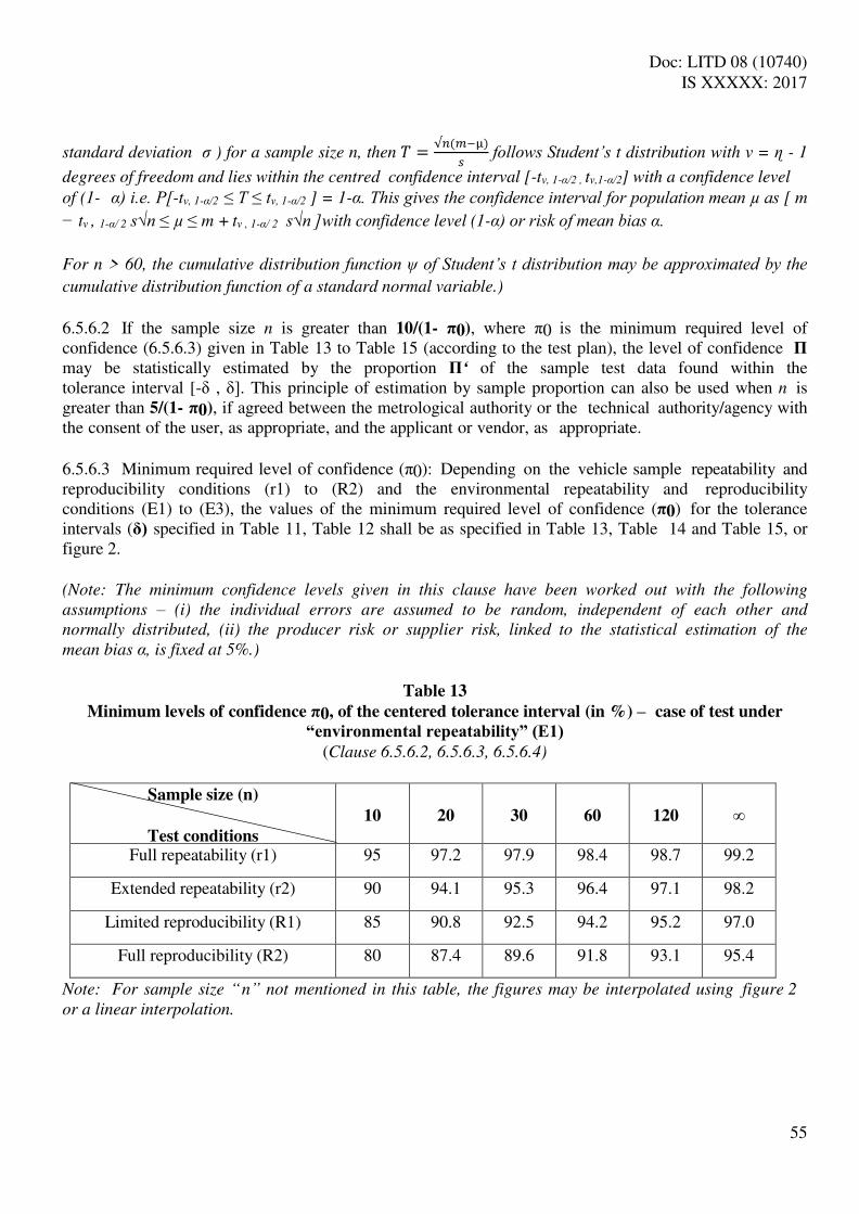
Doc: LITD 08 (10740) IS XXXXX: 2017
55
standard deviation σ ) for a sample size n, then = √ −µ follows Student’s t distribution with v = ɳ - 1
degrees of freedom and lies within the centred confidence interval [-tv, 1-α/2 , tv,1-α/2] with a confidence level
of (1- α) i.e. P[-tv, 1-α/2 ≤ T ≤ tv, 1-α/2 ] = 1-α. This gives the confidence interval for population mean µ as [ m
− tv , 1-α/ 2 s√n ≤ µ ≤ m + tv , 1-α/ 2 s√n ]with confidence level (1-α) or risk of mean bias α.
For n > 60, the cumulative distribution function ψ of Student’s t distribution may be approximated by the cumulative distribution function of a standard normal variable.)
6.5.6.2 If the sample size n is greater than 10/(1- π0), where π0 is the minimum required level of confidence (6.5.6.3) given in Table 13 to Table 15 (according to the test plan), the level of confidence Π
may be statistically estimated by the proportion Π‘ of the sample test data found within the tolerance interval [-δ , δ]. This principle of estimation by sample proportion can also be used when n is greater than 5/(1- π0), if agreed between the metrological authority or the technical authority/agency with the consent of the user, as appropriate, and the applicant or vendor, as appropriate. 6.5.6.3 Minimum required level of confidence (π0): Depending on the vehicle sample repeatability and reproducibility conditions (r1) to (R2) and the environmental repeatability and reproducibility conditions (E1) to (E3), the values of the minimum required level of confidence (π0) for the tolerance intervals ( ) specified in Table 11, Table 12 shall be as specified in Table 13, Table 14 and Table 15, or figure 2. (Note: The minimum confidence levels given in this clause have been worked out with the following
assumptions – (i) the individual errors are assumed to be random, independent of each other and
normally distributed, (ii) the producer risk or supplier risk, linked to the statistical estimation of the
mean bias α, is fixed at 5%.)
Table 13
Minimum levels of confidence π0, of the centered tolerance interval (in %) – case of test under
“environmental repeatability” (E1) (Clause 6.5.6.2, 6.5.6.3, 6.5.6.4)
Sample size (n)
Test conditions
10
20
30
60
120
∞
Full repeatability (r1) 95 97.2 97.9 98.4 98.7 99.2
Extended repeatability (r2) 90 94.1 95.3 96.4 97.1 98.2
Limited reproducibility (R1) 85 90.8 92.5 94.2 95.2 97.0
Full reproducibility (R2) 80 87.4 89.6 91.8 93.1 95.4
Note: For sample size “n” not mentioned in this table, the figures may be interpolated using figure 2
or a linear interpolation.

Doc: LITD 08 (10740) IS XXXXX: 2017
56
Table 14
Minimum levels of confidence π0, of the centered confidence intervals (in %) – case of test under
“limited environmental reproducibility” (E2)
(Clause 6.5.6.3 & 6.5.6.4)
Sample size (n)
Test conditions
10
20
30
60
120
∞
Full repeatability (r1) 93.3 96.2 97.0 97.8 98.2 98
Extended repeatability (r2) 87.5 92.5 93.9 95.3 96.1 97.5
Limited reproducibility (R1) 81.9 88.7 90.7 92.7 93.9 96.0
Full reproducibility (R2) 76.6 84.9 87.4 90.0 91.5 94.3
Note: For sample size n not mentioned in this table, the figures may be interpolated using figure 2 or
a linear interpolation.
Table 15
Minimum levels of confidence π0, of the centered confidence intervals (in %) – case of test under
“full environmental reproducibility” (E3)
(Clause 6.5.6.2, 6.5.6.3, 6.5.6.4)
Sample size (n)
Test conditions
10
20
30
60
120
∞
Full repeatability (r1) 91.4 95.0 96.0 97.0 97.6 98.5
Extended repeatability (r2) 84.7 90.7 92.4 94.1 95.1 96.8
Limited reproducibility (R1) 78.6 86.4 88.7 91.1 92.5 95.0
Full reproducibility (R2) 73.0 82.3 85.1 88.1 89.8 93.1
Note: For sample size n not mentioned in this table, the figures may be interpolated using figure 2 or
a linear interpolation.
(Note: Table 13, Table -14 and Table 15 are based on COST 323 recommendations)

Doc: LITD 08 (10740) IS XXXXX: 2017
57
Fig. 2 Minimum specified levels of confidence π0 with respect to the test conditions
Note: This figure is taken from COST 323 document which uses the European convention of representing
decimal with “,” instead of “.” as per Indian or international convention.
6.5.6.4 For legal applications (like direct enforcement), higher confidence levels may be required, such as 99% or 99.5%. Even if such values exceed the values given in Table 13, Table 14 and Table 15, they may be obtained on a large enough tolerance on the considered criterion (i.e. using a lower statistical accuracy class). (Note: For a given system accuracy, higher the tolerance, higher the confidence level. So, if a WIM
system having statistical accuracy class X( 1) with π0 = π1 for a particular criterion is reclassified to a
lower accuracy class Y( 2) where 2 > 1, it will produce corresponding π0 = π2 for the same
criterion, such that π2 > π1 enabling use of higher confidence levels than those given in Table 13,
Table 14 and Table 15.)
6.5.6.5 For acceptance of a WIM system in a designated statistical accuracy class, the lower bound of the confidence level π determined in accordance with 6.5.6.1 or the confidence level Π 6.5.6.2, as may be applicable, shall be equal to or more than the minimum required level of confidence (π0) specified in 6.5.6.3 for each applicable data item. (Note: Depending on the type of WIM system and user specification, there may be additional criterion
for acceptance in a designated statistical accuracy class as shown in Table 16 specifying the limits of
error.)
6.5.7 Limits of Error (For Vehicle Mass, Axle Load, Wheel Load)
The limits of error with reference to statistical accuracy shall be determined by the upper bound or

Doc: LITD 08 (10740) IS XXXXX: 2017
58
lower bound or both upper and lower bounds, as applicable, on value of relative error (6.5.7.1) or statistical parameters (6.5.7.2) as appropriate, in accordance with Table 16 where is the tolerance interval width of the statistical accuracy class for the relevant data item and the value of k shall be as specified in Table 16 unless a different value is agreed between the user and the vendor.
Table 16
(Clause 7.5.2.2, 9.1.3.3.1, 9.3.2, A.11.3.4.1, A.113.4.2, 5.4.2 , 6.5.6.5 , 6.5.7)
Type of Test Domain of application
Type of Test Load/Vehicle
Error or statistical
parameters
Value of k Initial Verification
In-service Inspection
Static weighing WIM system
with static weighing capability
Standard weights or masses1
As specified in clause 6.5.7.1
0.5
1.0 Measurement of
impact force2
If specified by user
(9.1.3.2.2.3)
Reference impact force generator3
Weighing-in- motion
All WIM systems
Reference vehicles As specified in clause 6.5.7.2 a)
or 6.5.7.2 b)
0.8
1.0
(1) In accordance with clause 10.4.1 (2) This test shall be applicable only if specified in accordance with 9.1.3.2.2.3. (3) In accordance with clause 10.6.
6.5.7.1 Relative error: The upper bound on the absolute value of relative error for each and every individual measurement shall be k . 6.5.7.2 The limits on the value of relevant statistical parameters for the data item of relevance with statistical accuracy class tolerance interval width shall be as follows: a) min: If min is the minimum value of that yields lower bound of level of confidence (π)
using equation (1) given in 6.5.6.1 equalling the minimum required level of confidence (π0), then the
lower bound of min shall be k .
(Note: Mathematically, min is the minimum value of that satisfies the equation 𝝅0 = 𝜓(( − )/ − 𝜈,1− ⁄2 /√ ) − 𝜓((− − )/ + 𝜈,1− ⁄2 /√ ) where the values of 𝑎 d s derived
from errors Cl.A.11.3))
b) π or Π‘: The minimum required level of confidence π0 shall be the lower bound of the level of
Confidence, computed using equation (1) given in clause 6.5.6.1 with k in place of . (Note: Mathematically, K , and the values of 𝑎 d s derived from errors should satisfy the equation 𝜓((K − )/ − 𝜈,1− ⁄ 2 / √ n ) − 𝜓((−K − )/ + 𝜈,1− ⁄ 2 / √ n ) ≥ π0) .
Alternatively, if it is permissible to determine the level of confidence in accordance with the requirements
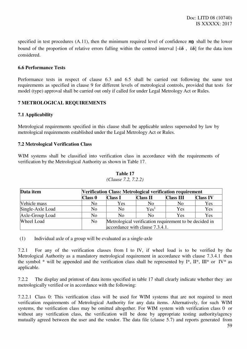
Doc: LITD 08 (10740) IS XXXXX: 2017
59
specified in test procedures (A.11), then the minimum required level of confidence π0 shall be the lower
bound of the proportion of relative errors falling within the centred interval [-k , k ] for the data item
considered.
6.6 Performance Tests
Performance tests in respect of clause 6.3 and 6.5 shall be carried out following the same test requirements as specified in clause 9 for different levels of metrological controls, provided that tests for model (type) approval shall be carried out only if called for under Legal Metrology Act or Rules. 7 METROLOGICAL REQUIREMENTS
7.1 Applicability
Metrological requirements specified in this clause shall be applicable unless superseded by law by metrological requirements established under the Legal Metrology Act or Rules. 7.2 Metrological Verification Class
WIM systems shall be classified into verification class in accordance with the requirements of verification by the Metrological Authority as shown in Table 17.
Table 17
(Clause 7.2, 7.2.2)
Data item Verification Class: Metrological verification requirement Class 0 Class I Class II Class III Class IV Vehicle mass No Yes No No Yes Single-Axle Load No No Yes1 Yes Yes
Axle-Group Load No No No Yes Yes Wheel Load No Metrological verification requirement to be decided in
accordance with clause 7.3.4.1. (1) Individual axle of a group will be evaluated as a single-axle
7.2.1 For any of the verification classes from I to IV, if wheel load is to be verified by the Metrological Authority as a mandatory metrological requirement in accordance with clause 7.3.4.1 then the symbol * will be appended and the verification class shall be represented by I*, II*, III* or IV* as applicable. 7.2.2 The display and printout of data items specified in table 17 shall clearly indicate whether they are metrologically verified or in accordance with the following: 7.2.2.1 Class 0: This verification class will be used for WIM systems that are not required to meet verification requirements of Metrological Authority for any data items. Alternatively, for such WIM systems, the verification class may be omitted altogether. For WIM system with verification class 0 or without any verification class, the verification will be done by appropriate testing authority/agency mutually agreed between the user and the vendor. The data file (clause 5.7) and reports generated from
Doc: LITD 08 (10740) IS XXXXX: 2017
60
the data file shall contain an associated clear warning that presented data on vehicle mass and/or single-axle loads or axle-group loads or wheel load, as applicable, are not metrologically verified. 7.2.2.2 Class I: This verification class will be used for WIM systems that are concerned only with determining the vehicle mass is required to be metrologically verified. The display and printout of single-axle loads or axle-group loads, as applicable, shall have an associated clear warning that these results are not metrologically verified. If applicable, and unless verification of wheel load is determined as mandatory metrological requirement, the display and printout of wheel load shall have an associated clear warning that these results are not metrologically verified. In addition to the vehicle mass, if the wheel load is to be metrologically verified, the verification class used will be Class I*. 7.2.2.3 Class II: This verification class will be used for WIM systems where individual axle loads are required to be metrologically verified. Under this verification class, individual axle of a group will be treated as a single-axle. The display and printout of vehicle mass or axle-group loads shall have an associated clear warning that these results are not metrologically verified. If applicable, and unless verification of wheel load is determined as mandatory metrological requirement, the display and printout of wheel load shall have an associated clear warning that these results are not metrologically verified. In addition to the individual axle loads, if the wheel load is to be metrologically verified, the verification class used will be Class II*. 7.2.2.4 Class III: This verification class will be used for WIM systems where single-axle loads and axle-group loads are required to be metrologically verified. The criteria for defining axle-groups shall be specified. The display and printout of vehicle mass and axle loads for axle of a group shall have an associated clear warning that these results are not metrologically verified. If applicable, and unless verification of wheel load is determined as mandatory metrological requirement, the display and printout of wheel load shall have an associated clear warning that these results are not metrologically verified. In addition to the single-axle loads and axle-group loads, if the wheel load is to be metrologically verified, the verification class used will be Class III*. 7.2.2.5 Class IV: This verification class will be used for WIM systems where vehicle mass, individual axle loads and axle-group loads are required to be metrologically verified. The criteria for defining axle-groups shall be specified. The display and printout of axle loads for axle of a group shall have an associated clear warning that these results are not metrologically verified. If applicable, and unless verification of wheel load is specified as mandatory metrological requirement, the display and printout of wheel load shall have an associated clear warning that these results are not metrologically verified. In addition to the vehicle mass, individual axle loads and axle-group loads, if the wheel load is to be metrologically verified, the verification class used will be Class IV*. 7.2.3 The requirement for verification of data items by the Metrological Authority is an additional requirement for WIM systems classified under verification class. The collection and processing requirements for these data items and other data items pertaining to the WIM system depending upon the type classification shall continue to apply in accordance with the provisions of clause 5.7.
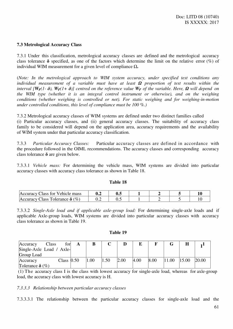
Doc: LITD 08 (10740) IS XXXXX: 2017
61
7.3 Metrological Accuracy Class
7.3.1 Under this classification, metrological accuracy classes are defined and the metrological accuracy class tolerance specified, as one of the factors which determine the limit on the relative error (%) of individual WIM measurement for a given level of compliance Ω.
(Note: In the metrological approach to WIM system accuracy, under specified test conditions any
individual measurement of a variable must have at least Ω proportion of test results within the
interval [Wr(1- ), Wr(1+ )] centred on the reference value Wr of the variable. Here, Ω will depend on
the WIM type (whether it is an integral control instrument or otherwise), and on the weighing
conditions (whether weighing is controlled or not). For static weighing and for weighing-in-motion
under controlled conditions, this level of compliance must be 100 %.)
7.3.2 Metrological accuracy classes of WIM systems are defined under two distinct families called (i) Particular accuracy classes, and (ii) general accuracy classes. The suitability of accuracy class family to be considered will depend on the application area, accuracy requirements and the availability of WIM system under that particular accuracy classification. 7.3.3 Particular Accuracy Classes: Particular accuracy classes are defined in accordance with the procedure followed in the OIML recommendations. The accuracy classes and corresponding accuracy class tolerance are given below. 7.3.3.1 Vehicle mass: For determining the vehicle mass, WIM systems are divided into particular accuracy classes with accuracy class tolerance as shown in Table 18.
Table 18
Accuracy Class for Vehicle mass 0.2 0.5 1 2 5 10 Accuracy Class Tolerance (%) 0.2 0.5 1 2 5 10
7.3.3.2 Single-Axle load and if applicable axle-group load: For determining single-axle loads and if applicable Axle-group loads, WIM systems are divided into particular accuracy classes with accuracy class tolerance as shown in Table 19.
Table 19
Accuracy Class for Single-Axle Load / Axle-Group Load
A B C D E F G H I1
Accuracy Class Tolerance (%)
0.50 1.00 1.50 2.00 4.00 8.00 11.00 15.00 20.00
(1) The accuracy class I is the class with lowest accuracy for single-axle load, whereas for axle-group load, the accuracy class with lowest accuracy is H.
7.3.3.3 Relationship between particular accuracy classes
7.3.3.3.1 The relationship between the particular accuracy classes for single-axle load and the

Doc: LITD 08 (10740) IS XXXXX: 2017
62
particular accuracy classes for vehicle mass shall be specified by the manufacturer. The relationship given in Table 20 shall be used for informative purpose (not mandatory).
Table 20
(Clause 7.3.3.3.1, 7.4.5, 7.5.2.3)
Accuracy Class for Single-
Axle load Accuracy Class for Vehicle mass
0.2 0.5 1 2 5 10
A ✓ L ✓L B ✓L ✓L ✓L C ✓L ✓L ✓L D ✓L ✓L ✓L E ✓ ✓L F ✓ ✓L G ✓ ✓ H ✓ I ✓
Note: ✓L is used to indicate that the relationship is valid for Low-speed WIM systems only under
current technological scenario.
7.3.3.3.2 The relationship between the particular accuracy classes for single-axle load and the particular accuracy classes for axle-group load shall be specified by the manufacturer. The relationship given in Table 21 shall be used for informative purpose (not mandatory).
Table 21
(Clause 7.3.3.3.2, 7.4.5, 7.5.2.3)
Accuracy Class for single-axle
load Accuracy Class for axle-group load
A B C D E F G H
A ✓ B ✓ C ✓ D ✓ E ✓ F ✓h ✓ G ✓h ✓ H ✓h ✓ I ✓h
Note: ✓h is used to indicate that the relationship is valid for High-speed WIM systems only under
current technological scenario.
7.3.4 General Accuracy Classes: General accuracy classes are defined and cor responding accuracy class tolerance are given in Table 22. (Note: The particular accuracy classes make it possible to work out many different configurations of
WIM systems. But the requirements of most applications can be covered by three particular accuracy
classes and two more accuracy classes defined for lower accuracy requirements than those afforded by

Doc: LITD 08 (10740) IS XXXXX: 2017
63
particular accuracy classes. These five accuracy classes are termed general accuracy classes.)
Table 22
(Clause 7.3.4 & 7.3.4.1)
Data Item General Accuracy Class: Accuracy Class Tolerance (%)
a(5) b(5) c(10) d(15) e
Vehicle mass 5 5 10 15 > 15
Axle Group Load 5 8 15 20 > 20
Single axle load 5 11 20 30 > 30
Wheel load 5 15 25 35 > 35
(Note: Currently only LSWIM systems are capable of complying with general accuracy class a(5).
HSWIM systems are capable of complying with general accuracy class c (10) and in some cases b(5), but
this situation may change in future with advancement in HSWIM technology)
7.3.4.1 The tolerance criteria given in Table 22 on wheel load shall be considered a mandatory metrological requirement and used for determining metrological accuracy class only if it is so specified by the user in writing or it is so requested by the applicant during model (type) approval (9.1.3.2.2.2.IV). Otherwise, the given tolerance criteria for wheel load shall be treated as reasonable acceptable values for WIM systems but shall not be mandatory for compliance. 7.4 Scale interval
7.4.1 For a particular WIM System, one unique scale interval (D) shall be used for indicating or printing of vehicle mass and another unique scale interval (d) shall be used for indicating or printing of axle loads and if applicable wheel loads. 7.4.2 The scale intervals of the indicating or printing devices shall be in the form 1×10s, 2×10s or 5×10s, s being a positive or negative whole number or zero. 7.4.3 The relationship among the accuracy classes, the value of the scale intervals and the maximum capacity expressed in scale intervals shall be as specified in Table 23 for indicating or printing of vehicle mass, and Table 24 for indicating or printing of axle loads and if applicable wheel loads.
Table 23
Scale interval for Vehicle mass, D
(Clause 7.4.3 & 7.4.6)
Metrological Accuracy Class Statistical Scale Interval for Maximum Capacity in scale intervals
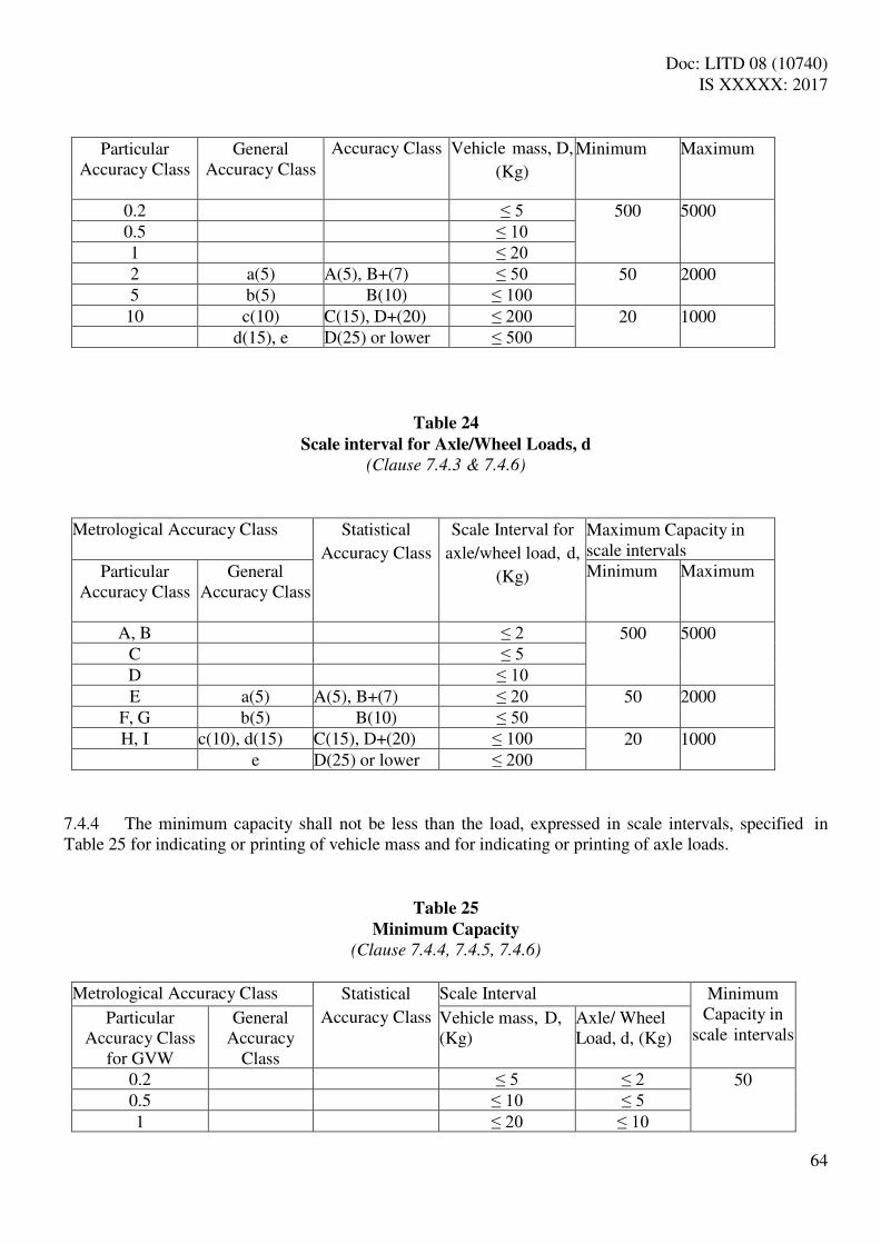
Doc: LITD 08 (10740) IS XXXXX: 2017
64
Particular Accuracy Class
General Accuracy Class
Accuracy Class Vehicle mass, D,
(Kg)
Minimum Maximum
0.2 ≤ 5 500 5000 0.5 ≤ 10 1 ≤ 20 2 a(5) A(5), B+(7) ≤ 50 50 2000 5 b(5) B(10) ≤ 100 10 c(10) C(15), D+(20) ≤ 200 20 1000
d(15), e D(25) or lower ≤ 500
Table 24
Scale interval for Axle/Wheel Loads, d
(Clause 7.4.3 & 7.4.6)
Metrological Accuracy Class Statistical
Accuracy Class
Scale Interval for
axle/wheel load, d,
(Kg)
Maximum Capacity in scale intervals
Particular Accuracy Class
General Accuracy Class
Minimum Maximum
A, B ≤ 2 500 5000 C ≤ 5 D ≤ 10 E a(5) A(5), B+(7) ≤ 20 50 2000
F, G b(5) B(10) ≤ 50 H, I c(10), d(15) C(15), D+(20) ≤ 100 20 1000
e D(25) or lower ≤ 200
7.4.4 The minimum capacity shall not be less than the load, expressed in scale intervals, specified in Table 25 for indicating or printing of vehicle mass and for indicating or printing of axle loads.
Table 25
Minimum Capacity
(Clause 7.4.4, 7.4.5, 7.4.6)
Metrological Accuracy Class Statistical
Accuracy Class
Scale Interval Minimum Capacity in
scale intervals Particular
Accuracy Class for GVW
General Accuracy
Class
Vehicle mass, D, (Kg)
Axle/ Wheel Load, d, (Kg)
0.2 ≤ 5 ≤ 2 50 0.5 ≤ 10 ≤ 5 1 ≤ 20 ≤ 10

Doc: LITD 08 (10740) IS XXXXX: 2017
65
2 a(5) A(5), B+(7) ≤ 50 ≤ 20
10 5 b(5) B(10) ≤ 100 ≤ 50 10 c(10), d(15) C(15), D+(20) ≤ 200 ≤ 100
e D(25) or lower ≤ 500 ≤ 200
7.4.5 The relationship between particular accuracy classes for axle loads and the minimum capacity can be obtained from Table 25, using Table 20 and/or Table 21 (to correlate the particular accuracy class for single-axle loads and, if required, axle-group load with the particular accuracy class for vehicle mass). 7.4.6 For a WIM system which is classified under a Statistical Accuracy Class and a Metrological Accuracy Class having different upper bounds for scale intervals, the lower of the two upper bounds will be chosen as the scale interval and the corresponding maximum capacity and minimum capacity values shall be decided in accordance with the requirements specified in Table 24 and Table 25, respectively. (Note: Table 23, Table 24 and Table 25 give the relationship between the accuracy classes, the scale
intervals and the maximum or minimum capacity. It does not seek to indicate the relationship
between the metrological accuracy classes and the statistical accuracy classes or the relationship
between the particular accuracy classes and the general accuracy classes, and should not be used to infer
any such relationship.)
7.5 Limits of Error (For Vehicle Mass, Axle Load, Wheel Load)
7.5.1 The limits of error for vehicle mass, axle loads (single-axle, axle-group) and/or wheel-load, as may be applicable in accordance with functional type classification (4), shall be:
the limits of error with respect to statistical accuracy class specified in 6.5.7, or the limits of error with respect to metrological accuracy class specified in 7.5, that is, the
maximum specified error ( ) (7.5.2) for the metrological accuracy class for a level of compliance (Ω) (7.5.3) equaling or exceeding a specified minimum required level of compliance (Ω0) (7.5.4), or
the limits of error specified in clause 6.5.7 and clause 7.5 7.5.2 Maximum Specified Error,
(Note: The criteria for determining the maximum specified error for weighing-in-motion and on
static weighing are not the same. In case of the former it is based on relative error and expressed as a
percentage whereas in case of the latter it is based on error and expressed as a number with unit (Kg).
This means, different values of will have to be used for weighing-in-motion and for static weighing.
Maximum permissible error is the same as maximum specified error with 100% level of compliance.)
7.5.2.1 Weighing-in-motion
The maximum specified error for weighing-in-motion will be the greatest of the absolute values of relative error specified in Table 26.

Doc: LITD 08 (10740) IS XXXXX: 2017
66
Table 26
Absolute values of relative error for weighing-in-motion
(Clause 9.1.3.3.2 & 9.3.2)
Data Item Type of Test Vehicle
Absolute values of relative error (%) Initial Verification In-service Inspection
Vehicle mass All types of vehicles
a) 0.5 × Accuracy Class Tolerance ( m), rounded to the nearest scale interval b) (D/Wr) × 100 × the number of axles in the totalization1
a) Accuracy Class Tolerance ( m),
rounded to the nearest scale interval b) (2D/Wr) × 100 × the number of axles in the totalization1
Axle Load (Single-Axle Load or Axle- Group Load)
Two-Axle Rigid
Vehicle2
c) 0.5 × Accuracy Class Tolerance ( s or g), rounded to the nearest scale interval d) (D/Ar) × 100 e) (2d/Ar) × 100
c) Accuracy Class Tolerance ( s or
g), rounded to the nearest scale interval d) (2D/Ar) × 100 e) (4d/Ar) × 100
All types of vehicles except Two-Axle Rigid
Vehicle2
f) Accuracy Class Tolerance ( s or g), rounded to the nearest scale interval g) (D/Ar) × 100 × the number of axles in the group3 h) (2d/Ar) × 100 × the number of axles in the group3
f) 2 × Accuracy Class Tolerance ( s or g), rounded to the nearest scale interval g) (2D/Ar) × 100 × the number of axles in the group3 h) (4d/Ar) × 100 × the number of axles in the group3
Wheel Load All types of vehicles
i) 0.5 × Accuracy Class Tolerance ( w), rounded to the nearest scale interval
i) Accuracy Class Tolerance ( w),
rounded to the nearest scale interval
(1) Number of axles in totalization for each reference vehicle will be the sum of the single axles and the axles of groups for the reference vehicle.
(2) Two-Axle Rigid Vehicle can be with four tyres or six tyres. (3) For single-axle the number of axles in group will be taken as 1.
(Note: If r is the relative error, the absolute value of relative error is given by r for r ≥ 0, whereas for r ≤ 0 it is given by -r. By using the modulus function, if r is the relative error, the absolute value of relative
error can be expressed as |r|. Maximum permissible is the same as maximum specified error used in this specification with minimum
level of compliance specified as 100 %.)
7.5.2.2 Static weighing
WIM system for which static weighing of test loads is possible in accordance with functional type classification (4), the maximum specified error on static weighing for increasing or decreasing load shall be the appropriate value of error given in Table 16 or Table 27, whichever is more, as appropriate for the

Doc: LITD 08 (10740) IS XXXXX: 2017
67
accuracy class of the WIM system.
Table 27
Maximum Specified Error on static weighing
(Clause 5.4.2, 7.5.2.3, 10.4.1, 7.5.2.2, A.7.2.1, A.7.2.3, A.7.2.5, A.7.2.6, A.7.2.7, A.7.2.8)
Metrological Accuracy Class Statistical
Accuracy Class
Load, m, expressed
in scale intervals
Absolute values of error (Kg)
Particular Accuracy Class for vehicle mass
General Accuracy
Class
Initial Verification
In-service Inspection
0.2 0 ≤ m ≤ 500 0.5 D 1.0 D 0.5 500 < m ≤ 2000 1.0 D 2.0 D 1 2000 < m ≤ 5000 1.5 D 3.0 D 2 a(5) 0 ≤ m ≤ 200 1.0 D 2.0 D 5 b(5) A(5), B+(7) 200 < m ≤ 2000 1.5 D 3.0 D
10 c(10), d(15) B(10) 0 ≤ m ≤ 20 1.0 D 2.0 D e C(15), D+(20) 20 < m ≤ 500 1.5 D 3.0 D
(Note: This clause can be applied to large scales or large-based sensors (i.e. longer than the tyre
footprint in the direction of the traffic flow sensors), which are able to measure static loads. In
particular cases it may be applied to some strip sensors, and may be extended with caution to sensors
calibrated with shock devices. Type 1 WIM systems and Type 5 WIM systems when used for applications
in the legal domain, are some of the WIM systems to which this clause is applicable.
If it is not possible to test a sensor with static loads due to the difficulty of placing the load, static
weighing tests may be carried out with simulated loads.
If e is the error, the absolute value of error is given by e for e ≥ 0, whereas for e ≤ 0 it is given by -e. By
using the modulus function, if e is the error, the absolute value of error can be expressed as |e|.)
7.5.2.3 The relationship between particular accuracy classes for axle loads and the maximum specified error on static weighing can be obtained from Table 27, using Table 20 and/or Table 21 (to correlate the particular accuracy class for single-axle loads and, if required, axle-group load with the particular accuracy class for vehicle mass). 7.5.3 Level of Compliance, Ω 7.5.3.1 The level of compliance (Ω) will be the proportion of data observed and recorded during weigh-in-motion test for which the absolute value of relative error is less than or equal to the maximum specified error for weighing-in-motion specified in 7.5.2.1. (Note: The level of compliance Ω is the same as the level of confidence Π obtained in accordance with
6.5.6.2 with [- . ] replacing [- . ] ).
7.5.3.2 The level of compliance shall be determined in accordance with the procedure specified in A.11.

Doc: LITD 08 (10740) IS XXXXX: 2017
68
7.5.4 Minimum Required Level of Compliance, Ω0
The minimum required level of compliance (Ω0) will depend on the type of WIM system, the data item (weighing-in-motion) or test item (static weighing), the type of test, and shall be the appropriate value as specified in Table 28.
Table 28: Minimum required level of compliance, Ω0 (Clause 7.5.4)
Type of test Data Item / Test Item Minimum level of compliance (%) for different types1 of
WIM Systems Type 1 Type 2 Type 3 Type 4 Type 5
Static Weighing2 Test Loads3 100 100(2) --- --- 100
Weighing-in- motion
Vehicle mass 100
95 Axle-group Load
Single axle load Wheel load
(1) Types of WIM systems are given in Table 1. (2) Applicable only for integral control instruments. (3) Test loads can be standard weights or standard masses.
7.6 Installation and testing of WIM systems
7.6.1 For WIM systems to be used in applications where the individual axle or axle-group loads are required, the installation and testing requirements specified in Annex B and Clause 11 respectively, shall be applicable. 7.6.2 The following effects on the weighing results should be taken into account - Lateral forces due to interactions of the control instrument with the vehicle; Forces on part of the vehicle by different transient behaviour and friction within the axle
suspensions Forces on part of the ramps if there are different levels between the control instrument and ramp
that could lead to varying distribution of the axle load 7.6.3 Further practical guidance on the installation and operation of WIM systems is provided in Annex C.
7.7 Agreement between Indicating and Printing Devices
For the same load, there shall be no difference between the weighing results provided by any two devices having the same scale interval. 7.8 Influence Quantities
For WIM systems to be used in applications in the legal domain, influence factor and disturbance tests
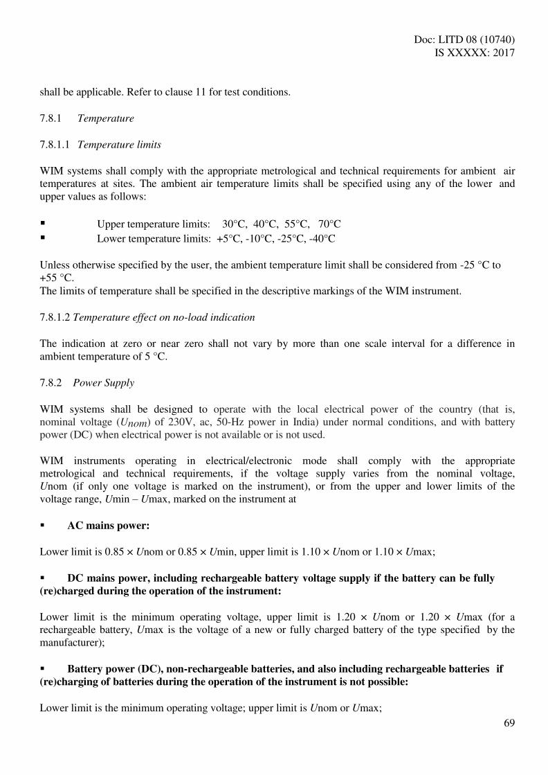
Doc: LITD 08 (10740) IS XXXXX: 2017
69
shall be applicable. Refer to clause 11 for test conditions. 7.8.1 Temperature
7.8.1.1 Temperature limits
WIM systems shall comply with the appropriate metrological and technical requirements for ambient air temperatures at sites. The ambient air temperature limits shall be specified using any of the lower and upper values as follows:
Upper temperature limits: 30°C, 40°C, 55°C, 70°C
Lower temperature limits: +5°C, -10°C, -25°C, -40°C Unless otherwise specified by the user, the ambient temperature limit shall be considered from -25 °C to +55 °C. The limits of temperature shall be specified in the descriptive markings of the WIM instrument. 7.8.1.2 Temperature effect on no-load indication
The indication at zero or near zero shall not vary by more than one scale interval for a difference in ambient temperature of 5 °C. 7.8.2 Power Supply
WIM systems shall be designed to operate with the local electrical power of the country (that is, nominal voltage (Unom) of 230V, ac, 50-Hz power in India) under normal conditions, and with battery power (DC) when electrical power is not available or is not used. WIM instruments operating in electrical/electronic mode shall comply with the appropriate metrological and technical requirements, if the voltage supply varies from the nominal voltage, Unom (if only one voltage is marked on the instrument), or from the upper and lower limits of the voltage range, Umin – Umax, marked on the instrument at AC mains power:
Lower limit is 0.85 × Unom or 0.85 × Umin, upper limit is 1.10 × Unom or 1.10 × Umax; DC mains power, including rechargeable battery voltage supply if the battery can be fully
(re)charged during the operation of the instrument:
Lower limit is the minimum operating voltage, upper limit is 1.20 × Unom or 1.20 × Umax (for a rechargeable battery, Umax is the voltage of a new or fully charged battery of the type specified by the manufacturer); Battery power (DC), non-rechargeable batteries, and also including rechargeable batteries if
(re)charging of batteries during the operation of the instrument is not possible:
Lower limit is the minimum operating voltage; upper limit is Unom or Umax;

Doc: LITD 08 (10740) IS XXXXX: 2017
70
12 V or 24 V motor vehicle battery power:
Lower limit is 9 V (for a 12 V battery) or 16 V (for a 24 V battery), upper limit is 16 V (for a 12 V battery) or 32 V (for a 24 V battery). (Note: The minimum operating voltage is defined as the lowest possible operating voltage below
which the electrical powered WIM instrument is automatically switched off.)
Battery-operated and DC mains powered WIM instruments shall either continue to function correctly or not indicate any mass or load values if the voltage is below the manufacturer’s specified value, the latter being larger than or equal to the minimum operating voltage.
7.9 Scale Interval for Stationery Load
For WIM systems having static weighing capability, if the scale interval for stationary loads is not equal to the scale interval, D (for tests on full-draught weighing) or d (for tests other than on full- draught weighing), it shall not be readily accessible when the instrument is in use for weighing-in- motion. In addition, if the instrument is not verified for use as a non-automatic weighing instrument (5.2.4), the scale interval for stationary loads shall not be readily accessible and shall only be used for static testing. 7.10 Operating Speed
WIM systems shall comply with the appropriate metrological and technical requirements at vehicle speeds within the operating speed range: given by the operating speed interlock; or determined during the weighing test Operating speed shall be indicated and/or printed only after the entire vehicle has been weighed in motion.
8 REQUIREMENTS FOR ELECTRONIC INSTRUMENTS
Electronic instruments forming a part of the WIM system shall comply with the following requirements, in addition to the applicable requirements of all other clauses. 8.1 General Requirements
8.1.1. Rated Operating Conditions
Electronic weighing instruments used in WIM systems shall be designed and manufactured so that they do not cause the WIM system to exceed, under rated operating conditions, the limits of error specified in clause 6.5.7 and/or clause 7.5, as may be applicable in accordance with functional type classification (4).

Doc: LITD 08 (10740) IS XXXXX: 2017
71
8.1.2. Disturbances
Electronic weighing instruments shall be designed and manufactured so that when they are exposed to disturbances either: a) Significant faults do not occur; or b) Significant faults are detected and acted upon as specified in 8.3.1. (Note: A fault equal to or less than 1 D or 1 d, as applicable, is allowed irrespective of the value of the
error of indication.)
8.1.3. Durability
The requirements in 8.1.1 and 8.1.2 shall be met durably in accordance with the intended use of the instruments. 8.1.4. Evaluation for Compliance
A type of an electronic weighing instruments is presumed to comply with the requirements in 8.1.1, 8.1.2 and 8.1.3 if it passes the examination and tests specified in clause A. 8.2 Application
The requirements in 8.1.2 may be applied separately to: a) Each individual cause of significant fault; and/or b) Each part of the electronic instruments. The choice of whether 8.1.2 a) or b) is applied is left to the manufacturer. 8.3 Functional Requirements
8.3.1 Acting upon a Significant Fault
When a significant fault has been detected, the instruments shall either be made in-operative automatically, or a visual or audible indication shall be provided and shall continue until the user takes action or the fault disappears. 8.3.2 Switch-On Procedure
Upon switch-on, a special procedure such as a display test facility which is automatically initiated at switch-on of indication (in the case of electronic instruments permanently connected to the mains at switch-on of indication) shall be performed that shows all relevant signs of the indicator in their active and non-active states sufficiently long to be checked by the operator. This is not applicable for non-segmented displays, on which failures become evident, for example screen-displays, matrix- displays, etc. 8.3.3 Influence Factors
An electronic weighing instrument shall comply with the requirements of 7.8, and in addition it shall

Doc: LITD 08 (10740) IS XXXXX: 2017
72
maintain its metrological and technical characteristics under specified climatic environment (5.9.4). 8.3.4 Warm-Up Time
During the warm-up time of an electronic weighing instrument, there shall be no indication or transmission of the weighing result and automatic operation shall be inhibited. 8.3.5 Interface
An instrument may be equipped with communication interfaces (See 3.2.7) enabling the coupling of the instrument to external equipment and user interfaces (See.3.2.8) permitting the exchange of information between a human user and the instrument. When an interface is used, the instrument shall continue to function correctly and its accuracy and metrological functions (including all metrologically relevant parameters and software) shall not be influenced. 8.3.5.1. Interface documentation
The documentation on the instrument interfaces shall include: a) A list of all commands (e.g. menu items); b) Description of the software interface; c) A list of all commands together; d) A brief description of their meaning and their effect on the functions and data of the instrument.
8.3.5.2. Securing of interfaces
Communication and user interfaces shall not allow the legally relevant software and functions of the instrument and its measurement data to be inadmissibly influenced by other interconnected instruments, or by disturbances acting on the interface. An interface through which the functions mentioned above cannot be performed or initiated, need not be secured. Other interfaces shall be secured as follows: a) Data shall be protected (e.g. with a protective interface as defined in 3.2.9) against accidental or deliberate interference during the transfer; b) All functions in the software interface shall be subject to the requirements for securing software in 5.10.2; c) All functions in the hardware interface shall be subject to the requirements for securing hardware in 5.10; d) It shall be easily possible to verify the authenticity and integrity of data transmitted to and from the instrument; e) Functions performed or initiated by other connected instruments through the interfaces shall meet the appropriate requirements of this specification. Other instruments or devices required by national regulations to be connected to the interfaces of an instrument in the WIM system shall be secured to automatically inhibit the operation of the WIM system for reasons of the non-presence or improper functioning of the required instrument or device.

Doc: LITD 08 (10740) IS XXXXX: 2017
73
9 METROLOGICAL CONTROLS
Consistent with the Legal Metrological Act or Rules, metrological controls of WIM system shall consist of the following:
model (type) approval;
initial verification;
subsequent verification;
in-service inspection Model (type) approval shall be done by the Metrological Authority. Other metrological controls shall be exercised by the Metrological Authority wherever required by law, and elsewhere by any testing authority or agency agreed between the user and the vendor. 9.1 Model (Type) Approval
9.1.1 Documentation
The application for model (type) approval of WIM system shall include documentation which provides the following information:
functional type classification (clause 4) with complete information (4.4);
metrological characteristics of the WIM system;
a standard set of specifications for the WIM system;
a functional description of the instruments, components and devices; drawings, diagrams and general software information, explaining the design, construction and
operation; any document or other evidence demonstrating that the design and construction of the
WIM system complies with the requirements of this document.
any other document required under Legal Metrology Act and Rules. 9.1.2 General Requirements
Model (type) evaluation shall be carried out on at least one, and normally not more than three, WIM system that represent the definitive model. At least one WIM system shall be completely installed at a typical site and if so required by the Metrological Authority, at least one WIM system shall be submitted, and if that is not possible then the major instruments shall be submitted, and if that too is not possible then at least the major components of the instruments shall be submitted; in a form suitable for simulation testing in a laboratory. The evaluation shall consist of the tests specified in 9.1.3. 9.1.3 Model (Type) Evaluation
The submitted documents shall be examined and tests carried out to verify that the WIM system complies with the:
functional type classification specified by the applicant consistent with clause 4;

Doc: LITD 08 (10740) IS XXXXX: 2017
74
technical requirements in clause 5;
metrological requirements in clause 7, particularly with reference to the appropriate limits of error when using the range of reference vehicles (10.5) and operating conditions specified by the manufacturer;
accuracy requirement in clause 6.5, particularly with reference to the appropriate limits of error (6.5.7) when using the range of reference vehicles (10.5), and operating conditions specified by the manufacturer, if statistical accuracy class is specified under clause 9.1.1 consistent with the functional type classification;
Requirements for electronic instruments in clause 8.
The appropriate metrological authority shall:
conduct the tests in a manner which prevents unnecessary commitment of resources; permit the results of these tests to be assessed for initial verification when the same
instrument is involved; Ensure that an instrument used in non-automatic (static) operation in accordance with 5.2.4,
meets the weighing performance test requirements for non-automatic weighing instruments published in Seventh Schedule-Heading-A of the Legal Metrology (General) Rules.
(Note: OIML advises the Metrological Authority to accept, with the consent of the applicant, test data
obtained from other metrological authorities without repeating the tests.)
9.1.3.1 In-motion tests
A complete WIM system, and if applicable complete WIM instrument(s) shall be tested: in accordance with functional type classification using statistical principles in clause 6 or
metrological principles in clause 7 or both; in accordance with the test methods in clause 10, using the range of reference vehicles specified
in 10.5 and applicable test plans and test conditions specified in 10.7;
Under the rated operating conditions in accordance with the model (type) specification.
9.1.3.2 Determination of errors for automatic weighing
9.1.3.2.1 For data item(s) of relevance, the error and the relative error shall be determined for normal automatic weighing operation using test value and reference values for reference vehicles, as applicable. (Note: For a data item represented by the suffix j, if 𝐼 is the test value of the data item, and is the
reference value of the data item, then the error and the relative error 𝑥 shall be = 𝐼 −
and 𝑥 = 𝐼 −𝑅𝑅 ) ) 9.1.3.2.2 Test value and Reference value
9.1.3.2.2.1 Vehicle mass
Test value: The test value for vehicle mass shall be the indicated reference vehicle mass observed and recorded (10.11) as appropriate.

Doc: LITD 08 (10740) IS XXXXX: 2017
75
Reference value: The reference value for vehicle mass shall be the conventional true value of the reference vehicle mass as defined (10.9) as appropriate. 9.1.3.2.2.2 Axle load (single–axle, axle-group, axle of a group) and Wheel load
Subject to the provisions of clause 9.1.3.2.2.3, the test value and reference value of wheel load and/or axle load for singe-axle, axle-group, and/or axle of a group, as may be applicable, shall be as follows: (I) Axle load (single-axle)
The requirements in this subclause are only applicable to WIM systems which are designated to determine single-axle loads. 1. Test value: The test value of single-axle load shall be the indicated single-axle load of the reference vehicle observed and recorded (10.12) as appropriate. 2. Reference value: The reference value of single-axle load shall be one of the following in accordance with the axle type of the reference vehicle: (a) For two-axle rigid reference vehicle, the conventional true value of static reference single-axle
load (10.10) as appropriate determined through static weighing test. (b) For all other reference vehicle axle types, the corrected mean single-axle load (10.16) as
appropriate determined through in motion test. For applications where vehicle mass is not required to be determined or for applications other than those in the legal domain, and if so agreed between the user or the metrological authority or testing authority/agency as appropriate and the applicant or vendor as appropriate, it shall be permissible to use the mean single-axle load (10.14.1) as appropriate in place of corrected mean single-axle load in clause 9.1.3.2.2.2.I.2 (b).
(Note: Examples of applications where vehicle mass is not required are axle load surveys or any
other application where WIM systems with Type f or Type f* vehicle data type are to be used)
(II) Axle-group load
The requirements in this subclause are only applicable to WIM systems which are designated to determine axle-group loads. 1. Test value: The test value of axle-group load shall be one of the following: (a) For WIM systems which determine and indicate the loads independent of single-axles or axle- group, by summation of individual axle loads for the axle-group of the reference vehicle, observed and recorded as single-axle loads (10.12) as appropriate, in accordance with national regulations for axle-group load. (b) For WIM instruments which automatically determine and indicate single-axle loads and axle- group loads separately, by the indicated axle-group load of the reference vehicle observed and recorded (10.12) as appropriate.

Doc: LITD 08 (10740) IS XXXXX: 2017
76
2. Reference value: The reference value of axle-group load shall be one of the following: (a) For WIM systems which determine and indicate the axle loads independent of single-axles or axle-group, the summation of corrected mean individual axle load (10.16) as appropriate for the axle-group of the reference vehicle, determined in accordance with national regulations for axle- group load through in motion test,. (b) For WIM instruments which automatically determine and indicate single-axle loads and axle- group loads separately, by the corrected mean axle-group load (10.16) as appropriate of the reference vehicle, determined through in motion test. For applications where vehicle mass is not required to be determined or for applications other than those in the legal domain, and if so agreed between the user or the metrological authority or testing authority/agency as appropriate and the applicant or vendor as appropriate, it shall be permissible to use the mean individual axle load (10.14.4) as appropriate in place of corrected mean individual axle load in clause 9.1.3.2.2.2.II.2.(a), if applicable. For applications where vehicle mass is not required to be determined or for applications other than those in the legal domain, and if so agreed between the user or the metrological authority or testing authority/agency as appropriate and the applicant or vendor as appropriate, it shall be permissible to use the mean axle-group load (10.14.2) as appropriate in place of corrected mean axle-group load in clause 9.1.3.2.2.2.II.2.(b), if applicable. (Note: Examples of applications where vehicle mass is not required are axle load surveys or any
other application where WIM systems with Type f or Type f* vehicle data type are to be used)
(III) Axle load (axle of a group)
The requirements in this subclause are only applicable to WIM systems which are designated to determine axle load for axle of a group in compliance with specified statistical accuracy requirements, and so mentioned in the application for model (type) approval, subject to any exception or exclusion that may be mentioned in the said application. 1. Test value: The test value of axle load for axle of a group shall be the indicated axle load for axle of a group of the reference vehicle observed and recorded (10.12) as appropriate. 2. Reference value: The reference value of axle load for axle of a group shall be the corrected mean axle load for axle of a group (10.16) as appropriate of the reference vehicle, determined through in motion test. For applications where vehicle mass is not required to be determined or for applications other than those in the legal domain, and if so agreed between the user or the metrological authority or testing authority/agency as appropriate and the applicant or vendor as appropriate, it shall be permissible to use the mean axle load for axle of a group (10.14.3) as appropriate in place of corrected mean axle load for axle of a group in clause 9.1.3.2.2.2.III.2.
(Note: Examples of applications where vehicle mass is not required are axle load surveys or any

Doc: LITD 08 (10740) IS XXXXX: 2017
77
other application where WIM systems with Type f or Type f* vehicle data type are to be used)
(IV) Wheel load
The requirements in this subclause are only applicable to WIM systems which are designated to determine wheel load with mandatory compliance to metrological accuracy requirements or performance requirements, and so mentioned in the application for model (type) approval. 1. Test value: The test value of wheel load for automatic weighing shall be the indicated wheel load of the reference vehicle observed and recorded (10.13) as appropriate. 2. Reference value: The reference value of wheel load shall be the corrected mean wheel load (10.17) as appropriate determined through in motion test. For applications where vehicle mass is not required to be determined or for applications other than in the legal domain, and if so agreed between the user or the metrological authority or testing authority/agency as appropriate and the applicant or vendor as appropriate, it shall be permissible to use the mean wheel load (10.15) appropriate in place of corrected mean wheel load in clause 9.1.3.2.2.2.IV.2. (Note: Examples of applications where vehicle mass is not required are axle load surveys or any
other application where WIM systems with Type f or Type f* vehicle data type are to be used)
9.1.3.2.2.3 Axle load and/or wheel load as impact force
If proposed by the applicant and agreed by the Metrological Authority, the test value and reference value of wheel load and/or axle load for single–axle, axle-group, or axle of a group as may be applicable, shall be as follows:
The test value shall be the indicated value of the impact force, consistent with the data item, imparted by the reference impact force generator (10.6), and observed and recorded (10.20) as appropriate; and the reference value shall be the known value of impact force, consistent with the data item, imparted by the reference impact force generator (10.6). (Note: For WIM systems whose primary objective is the measurement of true value of dynamic axle
loads or the true value of dynamic wheel loads with high accuracy, it may be more appropriate to use test
values and reference values given in clause 9.1.3.2.2.3 as compared to those given in clause
9.1.3.2.2.2.)
9.1.3.3 Limits of error
The limits of error shall be determined with reference to statistical accuracy class or metrological accuracy class or both in accordance with the functional type classification of the WIM system. 9.1.3.3.1 Limits of error with reference to statistical accuracy class
The limits of error with reference to the statistical accuracy class of a WIM system shall be determined in accordance with the procedure specified in A.9 and if applicable A.10 and A.11 as applicable for model (type) approval and using the value of k as specified in table 16 for initial verification, as

Doc: LITD 08 (10740) IS XXXXX: 2017
78
appropriate, and with the minimum required level of confidence (π0) as specified in clause 6.5.6.3 with reference to test plans (10.7) as applicable for model (type) approval. 9.1.3.3.2 Limits of error with reference to metrological accuracy class
The limits of error with reference to the statistical accuracy class of a WIM system shall be determined in accordance with the procedure specified in A.9 and if applicable A.10 and A.11 as applicable for model (type) approval with the maximum specified error shall be as specified in Table 26 for initial verification, as appropriate, and the minimum required level of compliance be as specified in Table 26 as applicable. 9.1.3.4 Simulation tests
Influence factors shall be applied during simulation tests in a manner that will reveal an alteration of the weighing result for any weighing process to which the WIM system could be applied, in accordance with clauses 7.8 and 8. Simulated tests shall be performed on complete WIM system unless the size and/or configuration of the instruments make it impossible to test them in their complete form. In such cases, testing is allowed with a load signal generator taking the place of load receptors. The Metrological Authority can accept a manufacturer's proposal to modify the method and manner in which simulated tests are performed, if suitable with regards to the specifics of the technology and design of the WIM systems’ measurement chain Simulation tests for determination of limits of error of module(s) with reference to statistical accuracy class shall not be mandatory for model (type) approval and shall be carried out only if specifically agreed between the applicant and the Metrological Authority and in accordance with mutually agreed procedure. 9.1.3.4.1 Apportioning of errors
Where modules of a WIM system or a WIM instrument, as the case may be, are tested separately the following requirements shall apply. For tests with reference to statistical accuracy class, if applicable, the error limits shall be determined in accordance with the procedure proposed by the applicant and agreed by the Metrological Authority. For tests with reference to metrological accuracy class: the error limits shall be equal to a fraction, pi, of the maximum specified errors or the allowed variations of the indication of the complete instrument or system, with accuracy class and level of compliance level taken to be the same as that of the complete WIM system or WIM instrument, as the case may be, f which the module is a part. The fractions pi shall satisfy the equation
The fraction, pi, shal l be chosen by the manufacturer of the modul e and shall be veri fied
by an appropriate test, taking into account the following conditions:
For purely digital devices, pi may be equal to 0;
For weighing modules, pi may be equal to 1; For all other modules (including digital load cells), pi shall not exceed 0.8 and shall not be less than

Doc: LITD 08 (10740) IS XXXXX: 2017
79
0.3, when more than one module contributes to the effect in question. For mechanical structures including weighbridges evidently designed and manufactured according to sound engineering practice, an overall fraction pi = 0.5 may be applied without any test, e.g. when levers are made of the same material and when the chain of levers has two planes of symmetry If the metrological characteristics of the load cell or other major component have been evaluated in accordance with the requirements of non-automatic weighing instruments published in Seventh Schedule-Heading-A of the Legal Metrology (General) Rules or the India Standard Specification for Electronic Weighing System (IS: 9281) or any other applicable Indian standard or any applicable OIML Recommendation (R 60, etc.), that evaluation shall be used to aid model (type) evaluation if so requested by the applicant. 9.1.4 Provision of Means for Testing
For the purposes of testing, the applicant may be required to furnish the Metrological Authority with the test vehicles, material, qualified personnel and a control instrument. The WIM system under test may be used as the control instrument provided that it complies with the requirements in 10.2.1. 9.1.5 Place of Testing
WIM system submitted for type approval may be tested at anyone of the following places: on a site at which all necessary tests can be conducted and agreed upon between the
Metrological Authority and the applicant;
at a laboratory considered appropriate by the Metrological Authority; at any other suitable place mutually agreed upon between the Metrological Authority and the
applicant. 9.2 Initial Verification
9.2.1 Tests
WIM systems shall be tested to verify that they comply with the requirements in clauses 5, 6 and 7 (except 7.8) for any vehicle(s) and product(s) loaded on a vehicle for which they are intended and when operated under normal conditions of use. Tests shall be carried out in-situ, in a normal installation, in respect of compliance with clauses 5, 6 (except 6.3) and 7, by the Metrological Authority for WIM systems with Verification Class I, II, III or IV; and by an appropriate testing authority or agency agreed between the user and the vendor for WIM systems with Verification Class 0 or without any specified verification class; in respect of compliance with clause 6.3 by an appropriate testing authority or agency agreed between the user and the vendor. The WIM system shall be installed so that an automatic weighing operation will be the same for testing as it is for a normal operation.
Doc: LITD 08 (10740) IS XXXXX: 2017
80
The Metrological Authority or the appropriate testing authority/agency agreed between the user and the vendor, as the case may be, shall conduct the tests in a manner that prevents an unnecessary commitment of resources. In appropriate situations and to avoid duplicating tests previously performed on the WIM system for model (type) evaluation under 9.1.3, the authority/agency may use the results of observed tests for initial verification. 9.2.1.1 In-motion tests
In-motion tests shall be conducted:
in accordance with the descriptive markings (5.12);
under the rated conditions for which the system is intended;
in accordance with the test methods in clause 10, with the reference vehicles in accordance with test plans and test conditions (if applicable) for initial verification (10.7.2). However, for systems to be used in applications in the legal domain where the axle load is required, the test utilizing the two-axle rigid reference vehicle must be conducted.
in accordance with test conditions applicable for initial verification in 10.7.2, if statistical accuracy is to be determined.
9.2.1.2 In-motion test error evaluation
9.2.1.2.1 Determination of error
Error and relative error shall be determined for data item of relevance in accordance with clause 9.1.3.2, provided that for determination of wheel load and/or axle loads the use of impact force measurements in accordance with 9.1.3.2.2.3 shall be permissible if agreed between the vendor and the Metrological Authority or other appropriate testing authority/agency, as applicable. 9.2.1.2.2 Limits of error
The limits of error shall be determined in accordance with clause 9.1.3.3 with reference to statistical accuracy class or metrological accuracy class or both as applicable under the functional type classification of the WIM system with the limits of error with reference to statistical accuracy class in accordance with the same provisions as in clause 9.1.3.3.1 with the exception that the test plans and test conditions (10.7.2) shall be as applicable for initial verification. 9.2.2 Provision of Means for Testing
For the purposes of testing, the applicant may be required to furnish the Metrological Authority or other appropriate testing authority/agency, as applicable, with the test vehicles, material, qualified personnel and a control instrument. The WIM system under test may be used as the control instrument provided that it complies with the requirements in 10.2.1. 9.2.3 Place of Testing
Initial verification tests shall be conducted entirely at the place of installation, and during testing the WIM system shall include all components and parts which form the system as intended for normal use.

Doc: LITD 08 (10740) IS XXXXX: 2017
81
9.3 Subsequent Metrological Control
9.3.1 Subsequent Verification
Subsequent verification shall be carried out in accordance with the same provisions as in 9.2 for initial verification. 9.3.2 In-Service Inspection
In-service inspection shall be carried out in accordance with the same provisions as in 9.2 for initial verification, with the following exceptions: (a) for determining the limits of error with reference to statistical accuracy class,
the test plan and test conditions (10.7.2) shall be as applicable for in-service inspection, for determining the minimum sample size in accordance with the provisions of clause 9.1.3.3.1 and for determining the minimum required level of confidence (π0) in accordance with the provisions of clause 9.1.3.3.2; and the value of k to be considered in accordance with clause 9.1.3.3.1 shall be as specified in table 16 for in-service inspection.
(b) In evaluating the limits of error with respect to metrological accuracy class, the maximum specified error shall be as specified in Table 26 for in-service inspection.
10 TEST METHODS
10.1 Test Procedures
10.1.1 Vehicle Mass
For the vehicle mass a complete WIM system shall be tested for compliance with the requirements specified in a) or b) or both, as may be applicable under the functional type classification (4): a) clause 6.5.4, using the range of vehicles specified in 10.5 and under test conditions specified in test plans (10.7) as appropriate, and if applicable also the integral control instrument (10.2.1) shall be tested. b) clause 7.3.3.1 or clause 7.3.4, as applicable, using the range of vehicles specified in 10.5, and if applicable also the integral control instrument (10.2.1) shall be tested. 10.1.2 Axle Loads and Wheel Load
10.1.2.1 Single–axle load and axle-group load
For single-axle loads, and if required axle-group loads, a complete WIM system shall be tested for compliance with the requirements specified in a) or b) or both a) and b), as may be applicable under the functional type classification (4): a) clause 6.5.4, using the range of vehicles specified in 10.5 and under test conditions specified in test plans (10.7) as appropriate. b) clause 7.3.3.2 or clause 7.3.4, as applicable, using the range of vehicles specified in 10.5.

Doc: LITD 08 (10740) IS XXXXX: 2017
82
10.1.2.2 Axle load (axle of a group)
If required under the functional type classification (4), and provided the user or applicant for model (type) approval, as the case may be, has specified it as a mandatory criteria for determination of statistical accuracy (6.4.5 and/or 9.1.3.2.2.2.III), for axle loads of axles of a group, a complete WIM system shall be tested for compliance with the requirements specified in clause 6.5.4, using the range of vehicles specified in 10.5 and under test conditions specified in test plans (10.7) as appropriate. If required under the functional type classification (4) but not specified as a mandatory criteria for determination of statistical accuracy by the user, the test procedure shall be as agreed between the user and the vendor. 10.1.2.3 Wheel load
If required under the functional type classification (4), and provided the user or applicant for model (type) approval, as the case may be, has specified it as either a mandatory criteria for determination of statistical accuracy (6.5.4 and/or 9.1.3.2.2.2.IV) and/or a mandatory metrological requirement (7.3.4.1 and/or 9.1.3.2.2.2.IV), for wheel loads a complete WIM system shall be tested for compliance with the requirements specified in a) or b) or both a) and b), as may be applicable: a) Clause 6.5.4, using the range of vehicles specified in 10.5 and under test conditions specified in test plans (10.7) as appropriate. b) Clause 7.3.4, using the range of vehicles specified in 10.5. If required under the functional type classification (4) but not specified as a mandatory criteria for determination of statistical accuracy or metrological accuracy by the user, the test procedure shall be as agreed between the user and the vendor. 10.2 Control Instrument
A control instrument for determining the conventional true value of each reference vehicle mass shall be available for testing. The control instrument may either be separate or integral. 10.2.1 Integral Control Instrument
The WIM system under test may be used as the control instrument provided that it: has an appropriate scale interval or scale interval for stationary load (7.9); and Complies with the requirements in 5.4. 10.2.2 Separate Control Instrument
10.2.2.1 Control instrument for full-draught vehicle weighing
A separate control instrument, capable of being used to determine the conventional true value of each reference vehicle mass by full-draught weighing when stationary, shall ensure the determination of the conventional true value of each reference vehicle’s mass to an error not greater than

Doc: LITD 08 (10740) IS XXXXX: 2017
83
a) one-third of the value of k , where the value of k is for in-motion tests in 6.5.7 as appropriate, and
is the statistical accuracy class tolerance for vehicle mass in 6.5.4, when statistical accuracy class is applicable in accordance with functional type classification, or b) one third of whichever is smaller of the metrological accuracy class tolerance(s) specified in accordance with 7.3, when metrological accuracy class is applicable in accordance with functional type classification, or the smaller of the two values obtained from a) and b), when both a) and b) are applicable in accordance with functional type classification. 10.2.3 Control Instrument for Static Reference Single-Axle Load of the Two-Axle Rigid Vehicle
As appropriate, a separate or integral control instrument, capable of being used to determine the conventional true value of the static reference single-axle loads by individual axle measurement when stationary, shall be used for tests with the two-axle rigid reference vehicle. The control instrument used for determining the static reference axle loads shall: (a) be able to support the entire contact area of all the tyres on the individual axle being weighed; (b) ensure the determination of the conventional true value of the static reference axle loads of the two-axle rigid reference vehicle to an error not greater than
(i) one-third of the value of k , where the value of k is for in-motion tests in 6.5.7 as appropriate, and is the statistical accuracy class tolerance for single-axle load in 6.5.4, when statistical accuracy class is applicable in accordance with functional type classification, or
(ii) one third of the value of the metrological accuracy class tolerance for single-axle load ( s) specified in accordance with 7.3, when metrological accuracy class is applicable in accordance with functional type classification, or
the smaller of the two values obtained from (b)(i) and (b)(ii), when both (b)(i) and (b)(ii) are applicable in accordance with functional type classification;
10.2.3.1 When scales built into the ground are to be used as control instrument, they shall be provided with approach and exit aprons in the same plane as the load receptor which shall extend to a length sufficient to fully support the two-axle rigid vehicle being weighed. The aprons shall have no longitudinal slope and not more than 1 % of transverse slope. Where this specification cannot be achieved, alternative means may be provided to ensure that all of the wheels of the reference vehicle are within ±3 mm of a horizontal or transversely-sloped plane passing through the load receptors during the weighing operations. 10.2.3.2 When portable scales laid on flat and horizontal ground are to be used as control instrument, preferably four numbers wheel scales or two numbers axle scales shall be used. If less than four numbers of wheel scales or less than two numbers of axle scales are used then steps or similar devices should be used to level all the wheels/axles so that the level difference between any two wheels is within ±2 mm or the slope is not more than 0.5%. (Note: Multi-platform weighbridges or vehicle scales, axle scales, wheel scales, etc. can be used as

Doc: LITD 08 (10740) IS XXXXX: 2017
84
control instrument for static reference axle load of two-axle rigid vehicle.)
10.3 Static Weighing Test for Integral Control Instruments
This test is applicable if the WIM system being verified is to be used as the control instrument for measuring the static reference axle loads of the two-axle rigid vehicle. 10.3.1 Test Loads
Errors shall be determined for test loads of: a) minimum capacity (7.4.4); b) maximum capacity (7.4.3); c) at least two load between a) and b) 10.3.2 Distribution of Test Loads
Except for eccentricity tests, standard weights or masses shall be evenly distributed on the load receptor. 10.3.3 Eccentricity Tests
Tests shall be carried out without excessive stacking or overlapping of the load on the load receptor provided that the conditions are practical and safe. 10.3.4 Repeatability tests
The repeatability error has to be determined with a load of about 50 % of Max which is placed 3 times on the load receptor. 10.4 Verification Standards
10.4.1 Weights
The standard weights or standard masses used for the type examination or verification of an instrument shall principally meet the specifications laid down in the Legal Metrology (General) Rules, 2011, in Part I of Fifth Schedule of the for weights up to 50 kg, and in Part III of Fifth Schedule of the for weights equal to or greater than 50 kg. The error of the standard weights or masses used shall not be greater than one-third of the maximum permissible error for the load, as specified in Table 27 for initial verification. 10.4.2 Substitution of Standard Weights
The test shall be carried out only during verification and at the place of use taking A.5.2.2.2 into account. When testing WIM system at the place of use (application), instead of standard weights any other

Doc: LITD 08 (10740) IS XXXXX: 2017
85
constant load may be used, provided that standard weights of at least 50 % of Max are used. Instead of 50 % of Max, the portion of standard weights may be reduced to:
35 % of Max if the repeatability error is ≤ 0.3 D; or 20 % of Max if the repeatability error is ≤ 0.2 D.
The repeatability error (10.3.4) shall be checked at a load of about the value at which the substitution is made, by placing this load three times on the load receptor. The results of the repeatability test (A.5.2.5) may be used if the test loads have a comparable mass. If the WIM system is provided with automatic zero-setting or zero-tracking device, it may be in operation during the tests, except for the temperature test. The error at zero point is then determined according to A.5.1.2.
10.5 Reference Vehicles
10.5.1 The type and number of reference vehicles to be used for testing shall represent the range of vehicles appropriate for the application for which the WIM system is intended to be used and representative of the traffic stream commonly encountered at the WIM site. The minimum number of reference vehicles of different types to be used for testing with reference to test plans shall be in accordance with Table 29.
Table 29
(Clause 10.5.1, 10.7.1.1 to 10.7.1.8)
Vehicle type Minimum number of vehicles under test plans
N01, N
02 N
03, N
04 N
05 N
06, N
07 N
08
Two-Axle, Four-Tyre, Rigid Vehicles
1
1
1 1 24
Two-Axle, Six-Tyre, Rigid Vehicles 60
Three-Axle, Rigid Vehicles A 1 105
Four-or-More Axle, Rigid Vehicles 15
Four-or-Less Axle, Semi-Articulated Vehicles
1
B
1
9
Five Axle, Semi-Articulated Vehicles 9 Six-or-More Axles, Semi-Articulated Vehicles 30
Five-or-Less Axle Truck-Trailer Combination
C
1
30
Six-Axle Truck-Trailer Combination 9 Seven-or-More Axle Truck-Trailer Combination
9
Total number of reference vehicles 1 2 3 4 300
For Test plan N05, two vehicle types shall be chosen out of the three vehicle types corresponding to A,
B and C, by assigning the numerical value 0 to A or B or C whichever corresponds to the one among the three that is least commonly encountered in the traffic stream at the WIM site, and assigning

Doc: LITD 08 (10740) IS XXXXX: 2017
86
the numerical value of 1 each to the other two. For any test plan, if the minimum numbers of vehicles for one or more types is not available in the traffic stream for a reasonable time during test, the shortfall shall be made up by increasing the numbers of vehicles from other types that are available in the traffic stream, maintaining closeness with the substituted vehicle types as far as possible. 10.5.2 Wherever one two-axle rigid vehicle is selected under the test plan, it shall be used both as the reference vehicle for determining the conventional true value of static reference single-axle loads and as one of the reference vehicles for in-motion tests. 10.5.3 The other reference vehicles shall be selected to cover, as far as practicable, the weighing range for which the instrument is approved. 10.5.4 When a particular WIM system is tested using a limited range of vehicle types (e.g. conventional steel leaf spring suspension systems only), this should be noted in the type approval certificate. 10.5.5 Vehicles carrying liquid loads or other products that that may be subjected to fluctuations in their centre of gravity when the vehicle moves, shall be used as reference vehicles only if the WIM system will be applied subsequently for determining the mass, or the loads of single-axles and/or axle-group of such vehicles. If the WIM system is not intended for this use, it shall bear the marking “not to be used to weigh vehicles carrying liquids or other products that may be subjected to fluctuations in their centre of gravity by vehicle movement”. 10.6 Reference Impact Force Generator
One or more equipment to be used as reference impact force generator(s), if so required under clause 9.1.3.2.2.3, shall be fully repeatable calibrated shock device(s) or pressure device(s) or instrumented truck or any other suitable device, as may be agreed between the parties involved in testing. 10.7 Test Plans
WIM systems shall be tested for accuracy under normal operation in accordance with standard test plans (10.7.1) as applicable (10.7.2). If appropriate, a higher order test plan (see note below) shall be used in accordance with government regulations. In case a higher order standard test plan is used, it should be noted in the type approval certificate or in the test reports of initial/subsequent verification or in-service inspection, as the case may be. It shall be permissible to test a WIM system with a lower order test plan provided the same is agreed between the user or the testing authority/agency, as appropriate, and the vendor in writing prior to the test. In case a lower order standard is used, it should be noted in the type approval certificate or in the test reports of initial/subsequent verification or in-service inspection, as the case may be. (Note: With the exception of N°5, a test plan will be of higher order if it is a higher plan indicated by
greater plan number or has a higher environmental condition indicated by a higher environmental
condition number. A plan will be same or higher order than N°5 if it includes all the reference
vehicles of N°5 and one or none more vehicles, each vehicle is tested in both loaded and unloaded

Doc: LITD 08 (10740) IS XXXXX: 2017
87
condition, the number of runs at different speeds for each loading condition is equal to or more than
those in N°5 for each reference vehicle and each speed, and the environmental condition higher than
equal to or more than E1.)
10.7.1 Standard Test Plans
10.7.1.1 Test plan N°1
One reference vehicle shall be chosen from the target group in accordance with Table 29, generally the one with the most common class on the WIM site or as specified by the user or the testing authority/agency, as appropriate, for making repeated runs. The reference vehicle shall be loaded either to the mean vehicle mass of the same type of vehicles in the traffic stream, or to 80% of the maximum vehicle mass legally permissible with a non-shifting, approximately symmetric (side to side) load. The test shall be carried out within a single day so that there is variation in temperature, climatic or environmental conditions. The number of runs at different speeds shall be in accordance with Table 30.
Table 30
(Clause 10.7.1.1, 10.7.1.2, 10.7.1.3, 10.7.1.4, 10.7.1.5, 10.7.1.6, 10.7.1.7, 10.7.1.8)
Reference
vehicle
Vehicle loading
Number of runs at different speeds1
Total number of runs
Test conditions (6.5.5)
Near vmin
Near 𝜈 Near vmax
Vehicle sample condition
Environmental condition
One representative
vehicle
Loaded
2
6
2
10
r1
E1
(1) Here vmin is the minimum operating speed; vmax is the maximum operating speed; and vm i s the speed at the centre of the operating speed range (see A.9.3.2). 10.7.1.2 Test plan N°2
One reference vehicle shall be chosen from the target group in accordance with Table 29, generally the one with the most common class on the WIM site, or as specified by the user or the testing authority/agency, as appropriate, for making repeated runs. The reference vehicle shall be tested in loaded and unloaded condition. The test shall be carried out within one to three consecutive days (E1) or over a week (E2) or over a few days in a month (E2), as appropriate. The number of runs at different speeds and loading conditions shall be in accordance with Table 31.
Table 31
(Clause 10.7.1.2)
Reference vehicle
Vehicle loading Number of runs at
different speeds1
Total number of runs
Test conditions (6.5.5)
Near vmin
Near 𝜈 Near vmax
Vehicle sample condition
Environmental condition
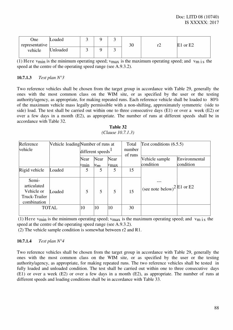
Doc: LITD 08 (10740) IS XXXXX: 2017
88
One representative
vehicle
Loaded 3 9 3
30
r2
E1 or E2 Unloaded 3 9 3
(1) Here vmin is the minimum operating speed; vmax is the maximum operating speed; and vm i s the speed at the centre of the operating speed range (see A.9.3.2). 10.7.1.3 Test plan N°3
Two reference vehicles shall be chosen from the target group in accordance with Table 29, generally the ones with the most common class on the WIM site, or as specified by the user or the testing authority/agency, as appropriate, for making repeated runs. Each reference vehicle shall be loaded to 80% of the maximum vehicle mass legally permissible with a non-shifting, approximately symmetric (side to side) load. The test shall be carried out within one to three consecutive days (E1) or over a week (E2) or over a few days in a month (E2), as appropriate. The number of runs at different speeds shall be in accordance with Table 32.
Table 32
(Clause 10.7.1.3)
Reference vehicle
Vehicle loading Number of runs at
different speeds1
Total number of runs
Test conditions (6.5.5)
Near vmin
Near 𝜈 Near vmax
Vehicle sample condition
Environmental condition Rigid vehicle Loaded 5 5 5 15
---
(see note below)2
E1 or E2
Semi- articulated Vehicle or
Truck-Trailer combination
Loaded
5
5
5
15
TOTAL 10 10 10 30
(1) Here vmin is the minimum operating speed; vmax is the maximum operating speed; and vm i s the speed at the centre of the operating speed range (see A.9.3.2). (2) The vehicle sample condition is somewhat between r2 and R1. 10.7.1.4 Test plan N°4
Two reference vehicles shall be chosen from the target group in accordance with Table 29, generally the ones with the most common class on the WIM site, or as specified by the user or the testing authority/agency, as appropriate, for making repeated runs. The two reference vehicles shall be tested in fully loaded and unloaded condition. The test shall be carried out within one to three consecutive days (E1) or over a week (E2) or over a few days in a month (E2), as appropriate. The number of runs at different speeds and loading conditions shall be in accordance with Table 33.

Doc: LITD 08 (10740) IS XXXXX: 2017
89
Table 33
(Clause 10.7.1.4)
Reference vehicle
Vehicle loading Number of runs at
different speeds1
Total number of runs
Test conditions (6.5.5)
Near vmin
Near 𝜈 Near vmax
Vehicle sample condition
Environmental condition
Rigid vehicle Loaded 3 9 3 15
R1
E1 or E2
Unloaded 3 9 3 15
Semi- articulated Vehicle or
Truck-Trailer combination
Loaded 3 9 3 15
Unloaded
3
9
3
15
TOTAL 12 36 12 60 (1) Here vmin is the minimum operating speed; vmax is the maximum operating speed; and vm i s the speed at the centre of the operating speed range (see A.9.3.2). . 10.7.1.5 Test plan N°5
One two-axle rigid vehicle and two other reference vehicles shall be chosen from the target group in accordance with Table 29, generally the ones with the most common class on the WIM site, or as specified by the user or the testing authority/agency, as appropriate, for making repeated runs. The three reference vehicles shall be tested in fully loaded and unloaded condition. The test shall be carried out within one to three consecutive days (E1) or over a week (E2) or over a few days in a month (E2), as appropriate. The number of runs at different speeds and loading conditions shall be in accordance with Table 34.
Table 34
(Clause 10.7.1.5)
Reference vehicle
Vehicle loading Number of runs at
different speeds1
Total number of runs
Test conditions (6.5.5)
Near vmin
Near vm
Near vmax
Vehicle sample condition
Environmental condition
Two-axle Rigid Loaded 5 5 5 15
R1
E1 or E2 Unloaded 5 5 5 15
First type2 Loaded 5 5 5 15 Unloaded 5 5 5 15
Second type2 Loaded 5 5 5 15 Unloaded 5 5 5 15
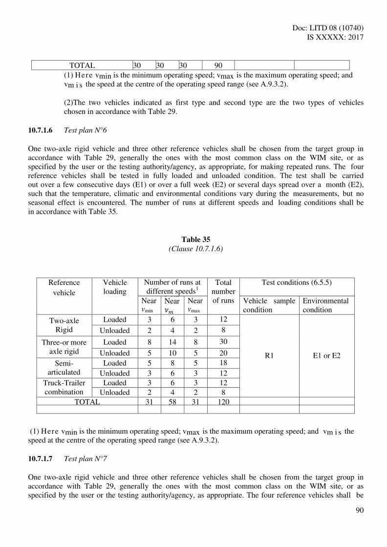
Doc: LITD 08 (10740) IS XXXXX: 2017
90
TOTAL 30 30 30 90 (1) Here vmin is the minimum operating speed; vmax is the maximum operating speed; and vm i s the speed at the centre of the operating speed range (see A.9.3.2). (2)The two vehicles indicated as first type and second type are the two types of vehicles chosen in accordance with Table 29.
10.7.1.6 Test plan N°6
One two-axle rigid vehicle and three other reference vehicles shall be chosen from the target group in accordance with Table 29, generally the ones with the most common class on the WIM site, or as specified by the user or the testing authority/agency, as appropriate, for making repeated runs. The four reference vehicles shall be tested in fully loaded and unloaded condition. The test shall be carried out over a few consecutive days (E1) or over a full week (E2) or several days spread over a month (E2), such that the temperature, climatic and environmental conditions vary during the measurements, but no seasonal effect is encountered. The number of runs at different speeds and loading conditions shall be in accordance with Table 35.
Table 35
(Clause 10.7.1.6)
(1) Here vmin is the minimum operating speed; vmax is the maximum operating speed; and vm i s the speed at the centre of the operating speed range (see A.9.3.2). 10.7.1.7 Test plan N°7
One two-axle rigid vehicle and three other reference vehicles shall be chosen from the target group in accordance with Table 29, generally the ones with the most common class on the WIM site, or as specified by the user or the testing authority/agency, as appropriate. The four reference vehicles shall be
Reference
vehicle
Vehicle loading
Number of runs at different speeds1
Total number of runs
Test conditions (6.5.5)
Near vmin
Near Near 𝜈
Near vmax
Vehicle sample condition
Environmental condition
Two-axle Rigid
Loaded 3 6 3 12
R1
E1 or E2
Unloaded 2 4 2 8
Three-or more axle rigid
Loaded 8 14 8 30
Unloaded 5 10 5 20
Semi- articulated
Loaded 5 8 5 18
Unloaded 3 6 3 12 Truck-Trailer combination
Loaded 3 6 3 12 Unloaded 2 4 2 8
TOTAL 31 58 31 120

Doc: LITD 08 (10740) IS XXXXX: 2017
91
tested in fully loaded and unloaded condition. The test shall be carried out in three phases within a month, with each phase completed in consecutive weeks (E2); or the three phases shall be spread out to cover coldest, hottest and medium season with each phase lasting for a full week or several days spread over a month, so that the system is subject to variations in temperature, climate, environment and seasons (E3). The number of runs at different speeds and loading conditions shall be in accordance with Table 36.
Table 36
(Clause 10.7.1.7)
Reference
vehicle
Vehicle loading
Number of runs at different speeds1 in
each phase
Total number
of runs in each phase
Total number of runs
Test conditions (6.5.5)
Near vmin
Near Near 𝜈
Near vmax
Vehicle sample condition
Environmental condition
Two-axle Rigid
Loaded 3 6 3 12 36
R1
E2 or E3
Unloaded 2 4 2 8 24
Three-or more axle rigid
Loaded 3 6 3 12 36
Unloaded 2 4 2 8 24
Semi- articulated
Loaded 3 6 3 12 36
Unloaded 2 4 2 8 24
Truck-Trailer combination
Loaded 3 6 3 12 36
Unloaded 2 4 2 8 24
TOTAL 20 40 20 80 240
(1) Here vmin is the minimum operating speed; vmax is the maximum operating speed; and vm i s the speed at the centre of the operating speed range (see A.9.3.2).
10.7.1.8 Test plan N°8
Reference vehicles shall be chosen from the traffic stream in accordance with Table 29 for each vehicle making one single run, and shall be weighed before or after the run using a control instrument. The reference vehicles shall cover, as far as practicable, the weighing range and the operating speed range of the WIM system. The test shall be carried out in three phases, with each phase lasting for about a week and the three phases spread over a month (E2); or with each phase lasting for several days spread over a month and the three phases spread out to cover coldest, hottest and medium season (E3). The number of runs shall be in accordance with Table 37.

Doc: LITD 08 (10740) IS XXXXX: 2017
92
Table 37
(Clause 10.7.1.8)
Reference
vehicle
Vehicle loading
Number of different vehicles making
single runs at
different speeds1 in each phase
Total number
of vehicle runs in each phase
Total number
of vehicle runs
Test conditions (6.5.5)
Near vmin
Near Near 𝜈
Near vmax
Vehicle sample condition
Environmental condition
Two-Axle, Four-Tyre, Rigid
Loaded 1 3 1 5 15
R2
E2 or E3
Unloaded 1 1 1 3 9
Two-Axle, Six-Tyre, Rigid
Loaded 3 6 3 12 36
Unloaded 2 4 2 8 24
Three-Axle, Rigid Vehicles
Loaded 5 13 5 23 69
Unloaded 3 6 3 12 36
Four-or-More Axle, Rigid
Loaded 1 1 1 3 9
Unloaded --- 1 1 2 6
Four-or-Less Axle, Semi- Articulated
Loaded 1 1 --- 2 6
Unloaded --- 1 --- 1 3
Five Axle, Semi- Articulated
Loaded 1 1 --- 2 6
Unloaded --- 1 --- 1 3
Six-or-More Axles, Semi- Articulated
Loaded 1 4 1 6 18
Unloaded 1 2 1 4 12
Five-or-Less Axle Truck-
Trailer Combination
Loaded 1 4 1 6 18
Unloaded 1 2 1 4 12
Six-Axle Truck-Trailer
Combination
Loaded 1 1 --- 2 6
Unloaded --- 1 --- 1 3
Seven-or- More Axle Truck-
Trailer Combination
Loaded 1 1 --- 2 6
Unloaded
---
1
--- 1 3
TOTAL 24 55 21 100 300 (1) Here vmin is the minimum operating speed; vmax is the maximum operating speed; and vm i s the

Doc: LITD 08 (10740) IS XXXXX: 2017
93
speed at the centre of the operating speed range (see A.9.3.2).
If vehicle with any loading condition given in Table 37 is not available in the traffic stream within a reasonable time during the test, the other loading condition may be substituted for that vehicle. 10.7.2 Selection of Test Plans
WIM systems shall be tested for accuracy under normal operation in accordance with the standard test plans specified in Table 38, for systems designated to comply with only statistical accuracy in accordance with functional type classification; or the standard test plans specified in Table 39, for systems designated to comply with only metrological accuracy in accordance with functional type classification; or
a common test plan constructed by merging or amalgamating the tests plans applicable under Table 38 for statistical accuracy and Table 39 for metrological accuracy, for WIM systems designated to comply with both statistical accuracy and metrological accuracy in accordance with functional type classification, so that the new test plan will be the same or a higher order plan than the corresponding standard plans of Table 38 and Table 39 with reference to the specified statistical accuracy and metrological accuracy, respectively, of the WIM system. Note: The test conditions i.e. vehicle sample condition and environmental condition are given within
brackets in Table 38 and table 39.
Table 38
(Clause 10.7.2, A.11.1)
Accuracy
Class
Standard test plans (test conditions): Accuracy class A B+ B C D+ or D E or lower
Model (type) approval
N°7 (R1, E3) N°7 (R1, E2) N°6 (R1, E2) N°6 (R1, E2)
N°4 (R1, E2) N°2 (r2, E2)
Initial verification
N°6 (R1, E2)
N°4 (R1, E2)
N°4 (R1, E1)
N°4 (R1, E1)
N°2 (r2, E1)
N°1 (r1, E1) Subsequent verification In-service inspection
N°4 (R1, E2) N°4 (R1, E1) N°3 (r*, E1)1 N°3 (r*,
E1)1
N°2 (r2, E1) N°1 (r1, E1)
1. r* denotes vehicle sample condition which is somewhat between r2 and R1 as defined in 6.5.5.
Table 39
(Clause 10.7.2, A.11.1)
WIM system application
type (4.1.1)
Standard test plans: Metrological accuracy class 0.2, 5, 1, 2 5 10 --- ---
a(5) b(5) c(10) d(15) e Type 1 N°5 Type 2 N°5 N°4
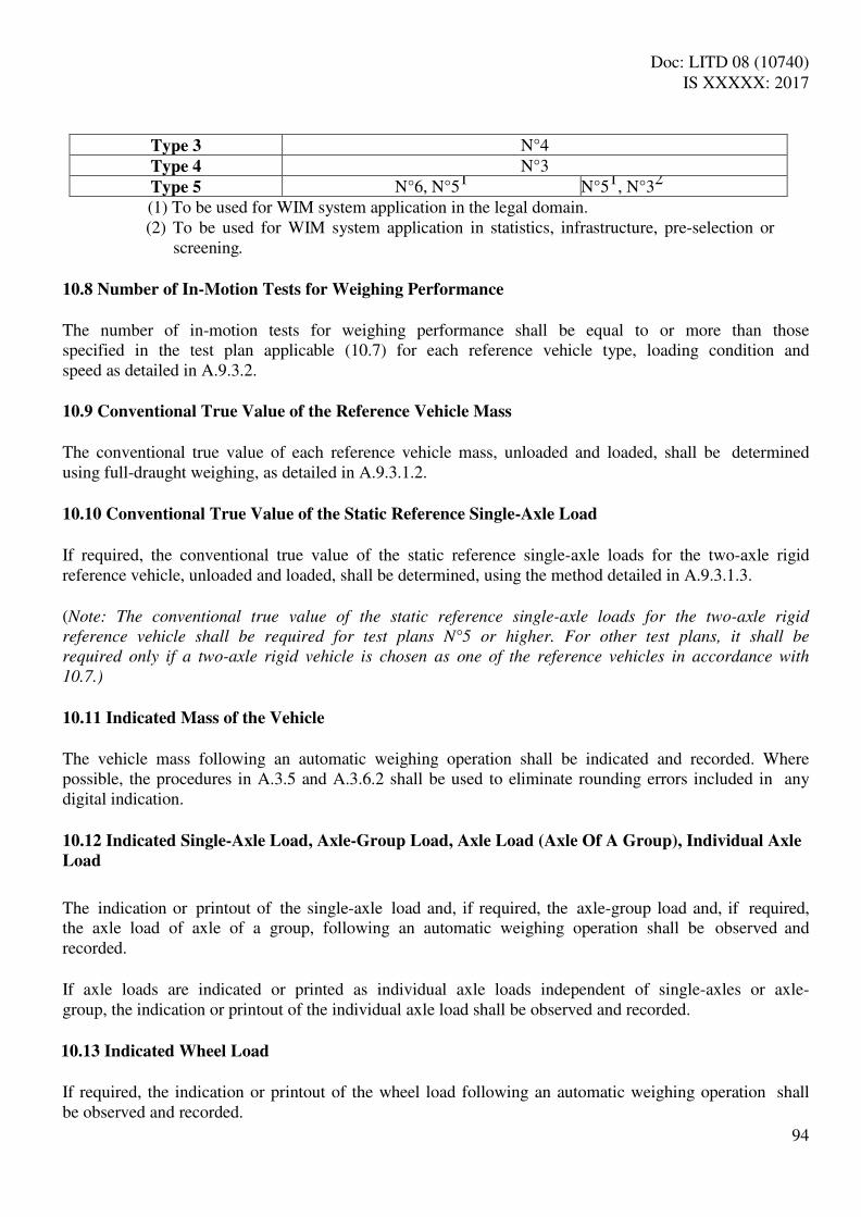
Doc: LITD 08 (10740) IS XXXXX: 2017
94
Type 3 N°4 Type 4 N°3 Type 5 N°6, N°51 N°51, N°32
(1) To be used for WIM system application in the legal domain. (2) To be used for WIM system application in statistics, infrastructure, pre-selection or
screening. 10.8 Number of In-Motion Tests for Weighing Performance
The number of in-motion tests for weighing performance shall be equal to or more than those specified in the test plan applicable (10.7) for each reference vehicle type, loading condition and speed as detailed in A.9.3.2.
10.9 Conventional True Value of the Reference Vehicle Mass
The conventional true value of each reference vehicle mass, unloaded and loaded, shall be determined using full-draught weighing, as detailed in A.9.3.1.2. 10.10 Conventional True Value of the Static Reference Single-Axle Load
If required, the conventional true value of the static reference single-axle loads for the two-axle rigid reference vehicle, unloaded and loaded, shall be determined, using the method detailed in A.9.3.1.3. (Note: The conventional true value of the static reference single-axle loads for the two-axle rigid
reference vehicle shall be required for test plans N°5 or higher. For other test plans, it shall be
required only if a two-axle rigid vehicle is chosen as one of the reference vehicles in accordance with
10.7.)
10.11 Indicated Mass of the Vehicle
The vehicle mass following an automatic weighing operation shall be indicated and recorded. Where possible, the procedures in A.3.5 and A.3.6.2 shall be used to eliminate rounding errors included in any digital indication. 10.12 Indicated Single-Axle Load, Axle-Group Load, Axle Load (Axle Of A Group), Individual Axle
Load
The indication or printout of the single-axle load and, if required, the axle-group load and, if required, the axle load of axle of a group, following an automatic weighing operation shall be observed and recorded. If axle loads are indicated or printed as individual axle loads independent of single-axles or axle- group, the indication or printout of the individual axle load shall be observed and recorded.
10.13 Indicated Wheel Load
If required, the indication or printout of the wheel load following an automatic weighing operation shall be observed and recorded.

Doc: LITD 08 (10740) IS XXXXX: 2017
95
10.14 Mean Single-Axle Load, Mean Axle-Group Load and Mean Axle Load (Axle Of A Group),
Individual Axle Load
10.14.1 The mean single-axle load shall be the sum of the indicated or printed axle loads obtained for each single axle on the reference vehicle during a series of weighing operations, divided by the number of single-axle load values recorded for each respective single axle. 10.14.2 The mean axle-group load shall be the sum of the indicated or printed axle-group loads recorded for each defined axle-group on the reference vehicle during a series of weighing operations, divided by the number of load values recorded for each respective axle-group. 10.14.3 The mean axle load (axle of a group) shall be the sum of the indicated or printed axle loads obtained for each axle of a defined axle group on the reference vehicle during a series of weighing operations, divided by the number of axle load values recorded for each respective axle of a defined axle group. 10.14.4 The mean individual axle load shall be the sum of the indicated or printed individual axle loads for each individual axle obtained independent of single-axles or axle-group on the reference vehicle during a series of weighing operations, divided by the number of individual axle load values recorded for each respective individual axle. 10.15 Mean Wheel Load
The mean wheel load shall be the sum of the indicated or printed wheel loads obtained for each wheel on the reference vehicle during a series of weighing operations, divided by the number of wheel load values recorded for each respective wheel. 10.16 Corrected Mean of the Single-Axle Load, Axle-Group Load, Axle Load (Axle of A Group)
The corrected mean of the axle loads for each single-axle or axle-group or axle of a group on a reference vehicle shall be the mean (10.14) of the recorded values (10.12) for the respective single- axles and axle-groups on the reference vehicle during a series of weighing operations, corrected proportionally (A.9.3.2.2.2 3) in relation to the systematic error of the instrument used for determining the recorded values. 10.17 Corrected Mean of the Wheel Load
The corrected mean of the wheel loads for each wheel on a reference vehicle shall be the mean (10.15) of the recorded values (10.13) for the wheels on the reference vehicle during a series of weighing operations, corrected proportionally (A.9.3.2.3) in relation to the systematic error of the instrument used for determining the recorded values.
10.18 Indicated Operating Speed The WIM system shall indicate and record the operating speed following an in-motion test (5.6.8). The

Doc: LITD 08 (10740) IS XXXXX: 2017
96
procedure given in A.9.3.2.4.2 shall be used to determine the operating speed and the error. 10.19 Indicated Acceleration
WIM system designated to estimate acceleration shall indicate and record the acceleration following an in-motion test (5.6.9). The procedure given in A.9.3.2.6 shall be used to determine the capability of the WIM system to detect operation beyond the threshold limit (5.7.15.17). (Note: Type 1a/ Type 1a*/Type 1d/Type 1d* WIM systems, and Type 2a/Type 2a*/Type 2d/Type 2d*
WIM system when installed off the main highway, are required to comply with the requirements of
10.19.)
10.20 Indicated Impact Load
WIM system designated to measure impact load in accordance with 9.1.3.2.2.3 shall indicate and record the impact force imparted as individual axle load. 10.21 Examination and Tests of Electronic Instruments
The examination and testing of an electronic weighing instrument is intended to verify compliance with the applicable requirements of this Specification and especially the requirements for electronic instruments in clause 8. The appropriate metrological authority, or if applicable and with the consent of the user, the appropriate testing authority/agency, may accept test data or certificate of compliance with the applicable requirements of this Specification and especially the requirements for electronic instruments in clause 8, obtained from other metrological authorities or testing authorities/agencies without repeating the examination and/or tests specified in this clause. 10.21.1 Examination
An electronic weighing instrument shall be examined to obtain a general appraisal of its design and construction. 10.21.2 Performance Tests
An electronic weighing instrument or electronic device, as appropriate, shall be tested as specified in clause 11 to determine its correct operation. Tests are to be conducted on the whole instrument except when the size and/or configuration of the instrument does not lend itself to testing as a unit. In such cases, the separate electronic devices shall be subjected to testing. It is not intended that electronic devices be further dismantled for separate testing of components. In addition, an examination shall be carried out on the fully operational weighing instrument or, if necessary, on the electronic devices in a simulated setup that sufficiently represents the weighing instrument. The equipment shall continue to function correctly as specified in Annex A 10.21.3 Span Stability Tests

Doc: LITD 08 (10740) IS XXXXX: 2017
97
This clause is applicable to WIM system for which testing with static load or simulated load is possible. When a particular WIM system uses weighing instrument that is not subjected to span stability test using static load or simulated load, this should be noted in the type (model) approval certificate. If applicable, the weighing instrument shall be subjected to span stability tests at various intervals before, during and after being subjected to performance tests. When an instrument is subjected to the span stability test specified in A.8: The maximum allowable variation in the errors of indication shall not exceed half the absolute value of the maximum specified error in 7.5.2.2 for initial verification for the test load applied on any of the n measurements. Where the differences of the results indicate a trend more than half the allowable variation specified above, the test shall be continued until the trend comes to rest or reverses itself, or until the error exceeds the maximum allowable variation.

Doc: LITD 08 (10740) IS XXXXX: 2017
98
Annex A
(Normative) Test Procedures for Weigh-In-Motion Systems for Road Vehicles
A.1 Examination for Type Approval
A.1.1 Documentation (9.1.1)
Review the documentation that is submitted, including necessary photographs, drawings, diagrams, general software information, relevant technical and functional description of main components, devices, etc. to determine if it is adequate and correct. Consider the operational manual. A.1.2 Compare Construction with Documentation (9.1.1)
Examine the various components of the WIM system to ensure compliance with the documentation. If required, examine the various devices of the WIM instrument(s) to ensure compliance with the documentation. A.1.3 Functional Type Classification (4)
Examine the system for conformity with the functional type classification.
A.1.4 Technical Requirements (5)
Examine the system for conformity with the technical requirements according to a checklist (see note below A.1.3).
A.1.5 Functional Requirements (8.3)
Examine the system for conformity with the functional requirements according to a checklist (see note below A.1.3).
A.2 Examination for Initial Verification
A.2.1 Compare Construction with Documentation (9.1.1)
Examine the system for conformity with the requirements in 5.12 for the approved model (type). A.2.2 Descriptive Markings (5.12)
Check the descriptive markings according to a checklist (see note below A.1.3). A.2.3 Verification Marks (5.13) and Securing Devices (5.10)

Doc: LITD 08 (10740) IS XXXXX: 2017
99
Check the arrangement for verification marks and securing according to a checklist (see note below A.1.3). A.3 General Test Conditions
A.3.1 Voltage Supply
Power up the equipment under test (EUT) for a time period equal to or greater than the warm-up time specified by the manufacturer and maintain the EUT energized for the duration of each test. A.3.2 Zero-Setting
This clause is applicable to WIM system for which static weighing of test loads is possible in accordance with functional type classification (4). When the EUT is not amenable to zero-setting (e.g. a piezoelectric sensor), this should be noted in the model (type) approval certificate and the test report. Adjust the EUT as closely as practicable to zero prior to each test, and do not readjust it at any time during the test, except to reset it if a significant fault has occurred. Certain tests require the automatic zero-setting and zero-tracking devices to be in operation (or not in operation). Where there is no specific requirement to this effect, the automatic zero-setting and zero- tracking devices shall be switched off. When this is done it shall be mentioned in the test report. A.3.3 Temperature
The tests shall be performed at a steady ambient temperature, usually normal room temperature unless otherwise specified. The temperature is deemed to be steady when the difference between the extreme temperatures noted during the test does not exceed one-fifth of the temperature range of the instrument(s) or 5°C whichever is less, and the rate of change does not exceed 5°C per hour. Note that this requirement does not apply to in-motion tests. The handling of the instrument(s) shall be such that no condensation of water occurs on the instrument. A.3.4 Recovery
After each test, allow the instrument(s) to recover sufficiently before the following test. (Note: A recovery time of 2 hours is recommended for influence factor tests)
A.3.5 Indication with a Scale Interval Not Greater than 0.2 d
If an instrument has a device for displaying the indication with a scale interval of 0.2 d or less, this device may be used to calculate the error. If such a device is used, it should be noted in the test report A.3.6 Control Instruments and Test Standards
A.3.6.1 Control instrument (10.2)

Doc: LITD 08 (10740) IS XXXXX: 2017
100
Control instruments meeting the requirements of 10.2 shall be used for weighing the vehicles. Where necessary, standard test weights meeting the requirements of 10.4.1 may be used to assess the rounding error. A.3.6.2 Use of standard weights to assess rounding error
This clause is applicable to WIM system for which static weighing of test loads is possible in accordance with functional type classification (4). (Note: Type 1 WIM systems and Type 5 WIM systems when used in applications that fall in the legal
domain are some of the WIM systems to which this clause is applicable.)
A.3.6.2.1 General method to assess error prior to rounding
For systems with digital indication having a scale interval for vehicle mass D, changeover points may be used to interpolate between scale intervals, i.e. to determine the indication of the system, prior to rounding, as follows: At a certain load, L, the indicated value, I, is noted. Additional weights, of say 0.1 D, are successively added until the indication of the instrument is increased unambiguously by one scale interval (I + D). The additional load, ΔL, added to the load receptor gives the indication, P, prior to rounding by using the following formula:
P = I + 0.5 D – ΔL
The error prior to rounding is: E = P – L = I + 0.5 D – ΔL – L For systems with digital indication having a scale interval for axle load d, the same procedure as given above for vehicle mass is followed for determining the indication of the system, prior to rounding, by using additional weights, of say 0.1 d, successively, totalling ΔL until the indication of the instrument is increased unambiguously by one scale interval from I to (I+ d) when the load is increased from L to (L +ΔL). The error prior to rounding is:
E = I + 0.5 d – ΔL – L
Example: An instrument with a scale interval, D, of 10 kg is loaded with 1000 kg and thereby indicates 1000 kg. After adding successive weights of 1 kg, the indication changes from 1000 kg to 1010 kg at an additional load of 3 kg. Inserted in the above formula, these observations give:
P = (1000 + 5 – 3) kg = 1002 kg Thus the true indication prior to rounding is 1 002 kg, and the error is:
E = (1002 – 1000) kg = 2 kg A.3.6.2.2 Correction for error at zero
Doc: LITD 08 (10740) IS XXXXX: 2017
101
Evaluate the error at zero load, E0, by the method of A.3.6.2.1. Evaluate the error at load L, E, by the method of A.3.6.2.1. The corrected error prior to rounding, Ec, is:
Ec = E – E0 Example: If, for the example in A.3.6.2.1, the error calculated at zero load was:
E0 = + 1 kg
Then the corrected error is:
Ec = + 2 – (+1) = + 1 kg
A.4 Test Program
A.4.1 Model (Type) Approval (9.1)
Clauses A.1 and, A.5 to A.9 shall normally be applied for model (type) approval. A.5.2 may be omitted if the WIM system under test is not to be used as an integral control instrument. The tests in A.6 to A.8 may be performed with static load, with a vehicle movement simulator (switches) used if necessary for the calculation of the weighing results. If the size and/or configuration of the instrument make it impossible to apply static load, testing may be done with simulated load using a load signal generator. The Metrological Authority can accept a manufacturer's proposal to modify the method and manner in which simulated functional tests are performed, if suitable with regards to the specifics of the technology and design of the weighing instruments measurement chain. A.4.2 Initial Verification (9.2)
A.2 and A.9 shall be applied for initial verification tests. If the WIM system under test is to be used as an integral control instrument, the tests in A.5.2 shall also be applied. The test in A.9 shall include all dynamic in-motion effects corresponding to normal operation of the WIM system. A.4.3 Subsequent Verification (9.3.1)
The tests shall be in accordance with the same provisions as in A.4.2 for initial verification with the exception that A.2 shall be applied only if there is a relocation or major modification of the WIM system.

Doc: LITD 08 (10740) IS XXXXX: 2017
102
A.4.4 In-Service Inspection (9.3.2)
A.9 shall be applied for in-service inspection and tests shall include all dynamic in-motion effects corresponding to normal operation of the WIM system. If the WIM system under test is to be used as an integral control instrument, the tests in A.5.2 shall also be applied. A.5 Performance Test During Type Evaluation
This clause is applicable to only those WIM system for which static weighing of test loads is possible in accordance with functional type classification (4). For WIM systems not amenable to static weighing of test loads, performance test shall be carried out in accordance with the manufacturers’ recommendation if so agreed between the metrological authority and the applicant for model (type) approval as appropriate. If that is not possible, it should be noted in the model (type) approval certificate of the WIM system that performance test was not carried out.
(Note: Type 1 WIM systems and Type 5 WIM systems when used in applications that fall in the legal
domain are some of the WIM systems to which this clause is applicable.)
A.5.1 Zero-Setting (5.3.1)
A.5.1.1 Range of zero-setting
A.5.1.1.1 Initial zero-setting
The initial zero-setting range shall comprise of the positive and negative portions of the initial zero- setting range. If the load receptor (platform and/or topcoat) cannot readily be removed, only the positive part of the initial zero-setting range need be considered. a) Positive range: With the load receptor empty (no external load), set the WIM instrument to zero. Place a test load on the load receptor or sensor and switch the instrument off and then back on. Continue this process until, after placing a load on the load receptor and switching the instrument off and on, it does not reset to zero. The maximum load that can be re-zeroed is the positive portion of the initial zero-setting range. b) Negative range:
1) Remove any load from the load receptor or sensor and set the instrument to zero. Then, if possible, remove the load receptor (platform and/or topcoat) from the instrument. If, at this point, the instrument can be reset to zero by switching it off and back on, the mass of the non-essential components is used as the negative portion of the initial zero-setting range. 2) If the instrument cannot be reset to zero with the load receptor (platform and/or topcoat) removed, add weights to any live part of the scale until the instrument indicates zero again. 3) Then remove the weights and, after each weight is removed, switch the instrument off and back on. The maximum load that can be removed while the instrument can still be reset to zero by

Doc: LITD 08 (10740) IS XXXXX: 2017
103
switching it off and on is the negative portion of the initial zero-setting range. 4) The initial zero-setting range is the sum of the positive and negative portions. 5) Alternatively, if it is not possible to test the negative range of initial zero-setting by removing the load receptor (platform and/or topcoat) of the instrument, then before proceeding to step 3) above, apply a test load greater than the permissible negative portion of the initial zero-setting range which can be calculated from the result of the positive range test. 6) If it is not possible to test the negative portion of the initial zero-setting range by these methods then only the positive part of the initial zero-setting range need be considered. 7) Reassemble or adjust the instrument for normal use after the above tests.
A.5.1.1.2 Semi-automatic zero-setting
This test shall not be carried out during the span stability test. This test is performed in the same manner as described in A.5.1.1.1, except that the zero-setting device is used rather than switching the instrument on and off. A.5.1.1.3 Automatic zero-setting
This test shall not be carried out during the span stability test. Remove the non-essential parts of the load receptor or re-adjust the instrument as described in A.5.1.1.1 and place weights on the live part of the scale until it indicates zero. Remove weights in small amounts and after each weight is removed allow the instrument to operate through the appropriate part of the automatic cycle so as to see if the instrument is reset to zero automatically. The maximum load that can be removed so that the instrument can still be reset to zero is the zero- setting range. A.5.1.2 Accuracy of zero-setting
A.5.1.2.1 Semi-automatic zero-setting
The accuracy of the zero-setting device is tested by setting the instrument to zero and then determining the additional load at which the indication changes from zero to one scale interval above zero. The error at zero is calculated according to the description in A.3.6.2.1. A.5.1.2.2 Automatic zero-setting or zero-tracking
The indication is brought outside of the automatic range. Then the additional load at which the indication changes from one scale interval to the next above is determined and the error is calculated according to the description in A.3.6.2.1. It is assumed that the error at zero load would be equal to the error at the load in question. A.5.2 Non-Automatic Tests Of the Integral Control Instrument (5.4)

Doc: LITD 08 (10740) IS XXXXX: 2017
104
(Note: The tests in this sub-clause are to be performed on the integral control instrument in-situ at the time
of model (type) approval or verification.)
A.5.2.1 Zero-setting
A.5.2.1.1 Accuracy of zero-setting (5.4.1)
Determination of the accuracy of zero-setting is carried out as described in A.5.1.2.1 or A.5.1.2.2, as appropriate. A.5.2.2 Determination of weighing performance
A.5.2.2.1 Preloading
Before the first weighing test, the WIM instrument(s) shall be preloaded once to near Max as appropriate. A.5.2.2.2 Static weighing test (10.3)
Apply loads from zero up to and including Max as appropriate, and then remove the loads back to zero. When determining the initial intrinsic error, at least ten different load values are selected, and for other weighing tests at least five are selected. The values of the loads selected shall include Max and Min, as appropriate, and values at or near those at which the maximum specified error (MSE) changes. It should be noted that when loading or unloading weights the load must be respectively increased or decreased in a uniform progression. The maximum permissible errors shall be the appropriate values from 7.5.2.2 for initial verification. A.5.2.3 Eccentricity test (5.4.2 and 10.3.3)
Apply a load equal to 1/3 Max as appropriate on each half of the load receptor. On an instrument with a load receptor having n points of support with n > 4 the fraction 1 / (n – 1) of Max shall applied to each point of support. The errors shall not exceed the appropriate maximum permissible errors from 7.5.2.2 for initial verification. A.5.2.4 Discrimination test (5.4.3)
The following tests are performed with three different loads, e.g. Min as appropriate, Max as appropriate and 0.5×Max. A load plus sufficient substitution material (e.g. 10 times 0.1 × scale interval) is placed on the load receptor. The additional material is then successively removed until the indication, I, is decreased unambiguously by one scale interval (to I – d or I – D as appropriate). Replace substitution material equivalent to 0.1×scale interval and then a load equal to 1.4×scale interval shall be gently placed on the load receptor and the result shall be increased by one scale interval above the initial indication (to I + d or I + D as appropriate).

Doc: LITD 08 (10740) IS XXXXX: 2017
105
A.5.2.5 Repeatability test (5.4.4 and 10.3.4)
Two series of weighings shall be performed, one with a load of about 50 % and one with a load close to 100 % of Max. Each series shall consist of at least three weighings. Readings shall be taken when the instrument is loaded, and when the unloaded instrument has come to rest between weighings. In the case of a zero deviation between the weighings, the instrument shall be reset to zero, without determining the error at zero. The true zero position need not be determined between the weighing’s. If the instrument is provided with automatic zero-setting or zero-tracking, it shall be in operation during the test. For initial verification, one test with about 50 % of Max is sufficient with no more than three weighings. A.6 Additional Functionality
A.6.1 Warm-Up Time Test (8.3.4)
This test is to verify that metrological performance of WIM instrument is maintained in the period immediately after switch on. The method is to check that automatic operation is inhibited until a stable indication is obtained and to verify that zero and span errors comply with the requirements during the first 30 minutes of operation and is applicable to only those WIM system for which static weighing of test loads is possible in accordance with functional type classification (4). 1) Disconnect the instrument from the power supply for a period of at least 8 hours prior to the test. 2) Reconnect the instrument and switch on while observing the indicating device. 3) Verify that it is not possible to initiate automatic weighing or printout until the indication has stabilized or until completion of the warm-up time if it is specified by the manufacturer (8.3.4). 4) As soon as the indication of the indicating device has stabilized, set the instrument to zero if this is not done automatically. 5) Determine the error of zero-setting by the method of A.3.6.2.1 and record this error as E0I (error of initial zero-setting) at first and as E0 when repeating this step. 6) Apply a load close to Max. Determine the error by the method of A.3.6.2.1 and A.3.6.2.2. 7) Verify that:
the zero indication error, E0I, is not greater than 0.25×scale interval as appropriate (5.3.1); the span error is not greater than the maximum specified error specified in 7.5.2.2 for initial verification 8) Repeat stages 5) and 6) after 5, 15 and 30 minutes. 9) After each time interval verify that:
the zero variation error (E0 – E0I) is not greater than 0.25 d × pi; the span error is not greater than the maximum specified error specified in 7.5.2.2 for initial verification. For WIM systems which uses instrument(s) not amenable to static weighing of test loads, other test methods which verify that metrological performance is maintained during the first 30 minutes of operation may be used in accordance with the manufacturers’ recommendation if so agreed between the
Doc: LITD 08 (10740) IS XXXXX: 2017
106
metrological authority or with the consent of the user the testing authority/agency as appropriate and the applicant for model (type) approval or the vendor as appropriate. If that is not possible, it should be noted in the model (type) approval certificate and the test certificate that metrological performance during the first 30 minutes of operation is not verified. A.6.2 Agreement between Indicating and Printing Devices (7.7)
If the WIM system has more than one indicating device, the indications of the various devices (both indicating and printing) are compared during the test. A.6.3 Operating Speed (5.6.8)
Verify that the automatic indication and printing of the operating speed contain a clear warning message if the speed is outside the specified range. A.6.4 Acceleration (5.6.9)
If the WIM system is designated to estimate acceleration, verify that the automatic indication and printing of the acceleration contain a clear warning message if the acceleration is outside the threshold limit. A.7 Influence Factor and Disturbance Tests
This clause is applicable to WIM system for which testing with static load or simulated load is possible. When a particular WIM system uses weighing instrument that is not subjected to influence factor and disturbance tests using static load or simulated load, this should be noted in the type (model) approval certificate. A.7.1 Test Conditions
The influence factor and disturbance tests are based on OIML R-134-1 (see 2.2) recommendations, CMI metrology regulation No. 0111-OOP-C010-10 (see 2.7) and BIS specifications. Further guidance on the metrological performance testing requirements for influence quantities and disturbances is provided in the appropriate reference standards as indicated for each test and in OIML D 11 [4].
A.7.1.1 General requirements
WIM instruments used for determining the vehicle mass, axle loads (single-axle and/or axle-group load and/or axle load of axle-of-a-group) as applicable, wheel load if applicable, shall comply with the influence factor and disturbance tests conditions and requirements specified in this Annex. Influence factor and disturbance tests are intended to verify that instruments can perform and function as intended in the environment and under the conditions specified. Each test indicates, where appropriate, the reference condition under which the intrinsic error is determined. It is not possible to apply these tests to an instrument that is performing an automatic operation. The

Doc: LITD 08 (10740) IS XXXXX: 2017
107
instrument shall therefore be subjected to the influence factors or disturbances under static conditions or simulated operation as defined herein. The permissible effects of the influence factors or disturbances, under these conditions, are specified for each case. When the effect of one influence factor is being evaluated, all other factors are to be held relatively constant, at a value close to normal. After each test the instrument shall be allowed to recover sufficiently before the following test. Where parts of the instrument are examined separately, errors shall be apportioned in accordance with 9.1.3.4.1. The operational status of the instrument or simulator shall be recorded for each test. When an instrument is connected in other than a normal configuration, the procedure shall be mutually agreed on by the approving authority/user and the applicant/vendor. A.7.1.2 Simulator requirements
A.7.1.2.1 General
If a simulator is used to test a module, the repeatability and stability of the simulator should make it possible to determine the performance of the module with at least the same accuracy as when a complete instrument is tested with weights, the limits of error to be considered being those applicable to the module. If a simulator is used, this shall be noted in the Test Report Format and its traceability referenced. A.7.1.2.2 Interfaces (8.3.5)
Susceptibility that would result from the use of electronic interfaces to other equipment shall be simulated in the tests. For this purpose it is sufficient to connect 3m of interface cable terminated to simulate the interface impedance of the other equipment. A.7.1.2.3 Documentation
Simulators shall be defined in terms of hardware and functionality by reference to the instrument under test, and by any other documentation necessary to ensure reproducible test conditions. This information shall be attached to, or shall be traceable from, the test report. A.7.2 Influence Factor Tests (7.8)
Summary of tests
Test Conditions § applied *
Static temperatures MSE* A.7.2.1

Doc: LITD 08 (10740) IS XXXXX: 2017
108
Temperature effect on no-load indication MSE A.7.2.2 Damp heat, steady-state MSE A.7.2.3
Resistance to specified high limit temperatures in off state MSE A.7.2.4.1
Resistance to specified low limit temperatures in off state MSE A.7.2.4.2
AC mains voltage variations MSE A.7.2.5
DC mains voltage variations, including rechargeable battery
if the battery can be fully (re)charged during the operation of MSE A.7.2.6 the instrument Battery voltage variations (DC), including non-rechargeable, and rechargeable battery if (re)charging of the battery during MSE A.7.2.7
the operation of the instrument is not possible
Voltage variations in 12 V or 24 V road vehicle batteries MSE A.7.2.8
Resistance to vibration A.7.2.9
Resistance to shock MSE A.7.2.10 Resistance to dust and water MSE A.7.2.11 *
maximum specified error (See 3.4.4.5) A.7.2.1 Static temperatures (7.8.1.1)
Static temperature tests are carried out according to IS: 9000 (Part 2) [10] and IS: 9000 (Part 3) [11] and according to Table A-1.
Table A-1
Environmental phenomena
Test specification Test setup
Temperature
Reference of 20 °C
Specified high for 2 hours IS: 9000 (Part 3)
Specified low for 2 hours IS: 9000 (Part 2)
Temperature of 5 °C, if the specified low temperature is ≤ 0 °C
IS: 9000 (Part 2)
Reference of 20 °C
Supplementary information to the BIS test procedures: Object of the test: To verify compliance with the provisions in 8.1.1 under conditions of Dry heat ( non-condensing) and co ld . The test in A.7.2.2 may be Conducted during this test. Preconditioning: 16 hours

Doc: LITD 08 (10740) IS XXXXX: 2017
109
Condition of the EUT: EUT is connected to the voltage supply and “on” for a time period equal to or greater than the warm-up time specified by the manufacturer. Voltage supply is to be “on” for the duration of the test. The zero-setting and zero-tracking facilities shall be enabled as for normal operation. If the test is performed together with A.7.2.2, automatic zero-setting and zero-tracking shall not be in operation.
Stabilization: 2 hours at each temperature under “free air” conditions. “Free air” conditions mean a minimum air circulation to keep the temperature at a stable level.
Temperature: As specified in 7.8.1.1
Temperature sequence: a) At the reference temperature of 20 °C;
b) At the specified high temperature;
c) At the specified low temperature;
d) At a temperature of 5 °C, if the specified low temperature is below
10 °C; and e) At the reference temperature.
Barometric pressure: Changes in barometric pressure shall be taken into account.
Number of test cycles: At least one cycle.
Test information: Adjust the EUT as close to zero indication as practicable prior to the test (if an automatic zero-tracking device is connected, adjust it to a value near zero). The EUT shall not be readjusted at any time during the test. After stabilization at the reference temperature and again at each specified temperature, apply at least five different test loads or simulated loads and record:
a) date and time;
b) temperature;
c) relative humidity;
d) test load;
e) indications (as applicable);
f) errors;
g) Functional performance. Maximum allowable variations:
All functions shall operate as designed. All errors shall be within the maximum specified errors specified in Table 27 of clause 7.5.2.2 for initial verification.
A.7.2.2 Temperature effect on the no-load indication (7.8.1.2)
Currently, there are no applicable standards. This test shall be conducted as described below. The instrument shall be set to zero and then changed to the prescribed highest and lowest temperatures
as well as to 5 °C if applicable. After stabilization the error of the zero indication shall be determined.
The change in zero indication per 5 °C shall be calculated. The changes in these errors per 5 °C are
calculated for any two consecutive temperatures of this test.
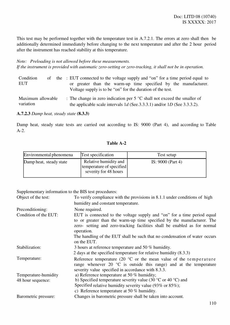
Doc: LITD 08 (10740) IS XXXXX: 2017
110
This test may be performed together with the temperature test in A.7.2.1. The errors at zero shall then be additionally determined immediately before changing to the next temperature and after the 2 hour period after the instrument has reached stability at this temperature.
Note: Preloading is not allowed before these measurements.
If the instrument is provided with automatic zero-setting or zero-tracking, it shall not be in operation.
Condition of the EUT
: EUT connected to the voltage supply and “on” for a time period equal to or greater than the warm-up time specified by the manufacturer. Voltage supply is to be “on” for the duration of the test.
Maximum allowable variation
: The change in zero indication per 5 °C shall not exceed the smaller of
the applicable scale intervals 1d (See.3.3.3.1) and/or 1D (See 3.3.3.2).
A.7.2.3 Damp heat, steady state (8.3.3)
Damp heat, steady state tests are carried out according to IS: 9000 (Part 4), and according to Table
A-2.
Table A-2
Environmental phenomena Test specification Test setup
Damp heat, steady state Relative humidity and temperature of specified
severity for 48 hours
IS: 9000 (Part 4)
Supplementary information to the BIS test procedures: Object of the test: To verify compliance with the provisions in 8.1.1 under conditions of high
humidity and constant temperature.
Preconditioning: None required. Condition of the EUT: EUT is connected to the voltage supply and “on” for a time period equal
to or greater than the warm-up time specified by the manufacturer. The zero- setting and zero-tracking facilities shall be enabled as for normal operation.
The handling of the EUT shall be such that no condensation of water occurs on the EUT.
Stabilization: 3 hours at reference temperature and 50 % humidity. 2 days at the specified temperature for relative humidity (8.3.3) Temperature: Reference temperature (20 °C or the mean value of the t em p e r a t u r e
range whenever 20 °C is outside this range) and at the temperature severity value specified in accordance with 8.3.3.
Temperature-humidity a) Reference temperature at 50 % humidity; 48 hour sequence: b) Specified temperature severity value (30 °C or 40 °C) and Specified relative humidity severity value (93% or 85%); c) Reference temperature at 50 % humidity. Barometric pressure: Changes in barometric pressure shall be taken into account.
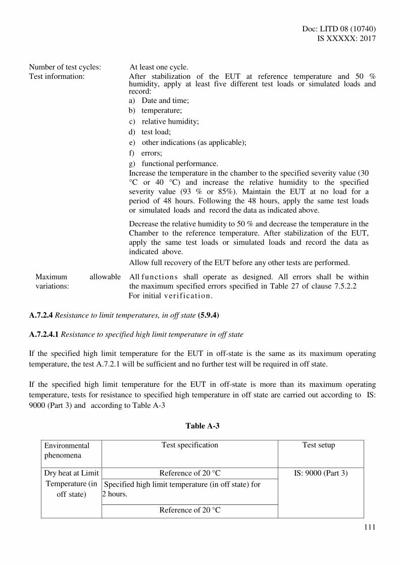
Doc: LITD 08 (10740) IS XXXXX: 2017
111
Number of test cycles: At least one cycle. Test information: After stabilization of the EUT at reference temperature and 50 %
humidity, apply at least five different test loads or simulated loads and record: a) Date and time; b ) temperature;
c ) relative humidity;
d ) test load;
e ) other indications (as applicable);
f) errors;
g ) functional performance. Increase the temperature in the chamber to the specified severity value (30 °C or 40 °C) and increase the relative humidity to the specified severity value (93 % or 85%). Maintain the EUT at no load for a period of 48 hours. Following the 48 hours, apply the same test loads or simulated loads and record the data as indicated above. Decrease the relative humidity to 50 % and decrease the temperature in the Chamber to the reference temperature. After stabilization of the EUT, apply the same test loads or simulated loads and record the data as indicated above.
Allow full recovery of the EUT before any other tests are performed. Maximum allowable All functions shall operate as designed. All errors shall be within variations: the maximum specified errors specified in Table 27 of clause 7.5.2.2 For initial veri f icat ion.
A.7.2.4 Resistance to limit temperatures, in off state (5.9.4)
A.7.2.4.1 Resistance to specified high limit temperature in off state
If the specified high limit temperature for the EUT in off-state is the same as its maximum operating
temperature, the test A.7.2.1 will be sufficient and no further test will be required in off state.
If the specified high limit temperature for the EUT in off-state is more than its maximum operating
temperature, tests for resistance to specified high temperature in off state are carried out according to IS:
9000 (Part 3) and according to Table A-3
Table A-3
Environmental phenomena
Test specification Test setup
Dry heat at Limit
Temperature (in
off state)
Reference of 20 °C IS: 9000 (Part 3) Specified high limit temperature (in off state) for
2 hours.
Reference of 20 °C

Doc: LITD 08 (10740) IS XXXXX: 2017
112
Supplementary information to the BIS test procedures:
Object of the test: To verify compliance with the provisions in 5.9.4 under conditions dry heat (non-condensing).
Preconditioning: None required
Condition of the EUT: EUT is disconnected from the voltage supply, in “off” state, and without any loading.
Stabilization: 2 hours at each temperature under “free air” conditions. “Free air” conditions mean a minimum air circulation to keep the temperature at a stable level.
Temperature: Specified high in accordance with 5.9.4
Temperature sequence: a) At the reference temperature of 20 °C b) At the specified high temperature; c) At the reference temperature.
Barometric pressure: Changes in barometric pressure shall be taken into account.
Number of test cycles: At least one cycle.
Test information: Maintain EUT in “off” state and without any loading throughout the three temperature stabilization sequence. At the end of the stabilization sequence, inspect EUT for damage and record findings.
Maximum allowable variations:
EUT shall not exhibit any damage and during the following functional test under static condition or simulated operation, all errors shall be within the maximum specified errors specified for initial verification, in 7.5.2.2 or 7.5.2.1, as applicable.
A.7.2.4.2 Resistance to specified low limit temperature in off state
If the specified low limit temperature for the EUT in off-state is the same as its minimum operating
temperature, the test A.7.2.1 will be sufficient and no further test will be required in off state.
If the specified low limit temperature for the EUT in off-state is less than its minimum operating
temperature, tests for resistance to specified high temperature in off state are carried out according to IS:
9000 (Part 2) [10] and according to Table A-4.
Table A-4
Environmental phenomena
Test specification Test setup
Cold at Limit
Temperature (in
Reference of 20 °C IS: 9000 (Part 2) Specified low limit temperature (in off state) for 2
hours

Doc: LITD 08 (10740) IS XXXXX: 2017
113
off state) Reference of 20 °C
Supplementary information to the BIS test procedures:
Object of the test: To verify compliance with the provisions in 5.9.4 under conditions of cold. Preconditioning: None required
Condition of the EUT: EUT is disconnected from the voltage supply, in “off” state, and without any loading.
Stabilization: 2 hours at each temperature under “free air” conditions. “Free air” conditions mean a minimum air circulation to keep the temperature at a stable level.
Temperature: Specified low in accordance with 5.9.4
Temperature sequence: a) At the reference temperature of 20 °C;
b) At the specified low temperature; c) At the reference temperature.
Barometric pressure: Changes in barometric pressure shall be taken into account.
Number of test cycles: At least one cycle.
Test information: Maintain EUT in “off” state and without any loading throughout the three temperature stabilization sequence. At the end of the stabilization sequence, inspect EUT for damage and record findings.
Maximum allowable variations:
EUT shall not exhibit any damage and during the following functional test under static condition or simulated operation, all errors shall be within the maximum specified errors specified for initial verification, in 7.5.2.2 or 7.5.2.1, as applicable.
A.7.2.5 AC mains voltage variations (7.8.2)
AC mains voltage supply variation tests are carried out according to Basic Standard IEC Publication
61000-2-1 [34] and IS: 14700 (Part 4/Sec 11) [20] and according to Table A-5.
Table A-5
Environmental phenomena
Test specification Test set up
Unom
AC mains voltage Upper limit: 1.10 × Unom or 1.10 × Umax IEC 61000-2-1,
variation Lower limit: 0.85 × Unom or 0.85 × Umin IS: 14700 (Part 4/Sec 11) /
Unom

Doc: LITD 08 (10740) IS XXXXX: 2017
114
Note: Where an instrument is powered by a three phase supply, the voltage variations shall apply for
each phase successively.
Supplementary information to the BIS / IEC test procedures: Object of the test: To verify compliance with the provisions in 8.1.1 under conditions of
AC mains voltage variations. Preconditioning: None required.
Condition of the EUT: The EUT is connected to the AC mains supply and “on” for a time period equal to or greater than the warm-up time specified by the manufacturer. Adjust the EUT as close to zero indication as practicable prior to the test and do not readjust at any time during the test except to reset if a significant fault has been detected.
Number of test cycles: At least one cycle.
Test information: The EUT shall be tested with a test or simulated load at or near Min and with one test load or simulated load between 50 % and the maximum capacity of the EUT.
Stabilize the EUT at the nominal voltage and record the following data:
a ) date and time;
b ) temperature;
c ) relative humidity;
d ) AC voltage supply;
e ) test loads; f) indications (as applicable);
g ) errors;
h ) functional performance.
Repeat the test for each of the voltages defined in IEC 61000-4-11 in section 5 (noting the need in certain cases for the test weighing to be repeated at both ends of the voltage range) and record the indications.
Maximum allowable All functions shall operate as designed. All errors shall be within the variations: maximum specified errors specified in Table 27 of clause 7.5.2.2 for Initial verification.
A.7.2.6 DC mains voltage variations (7.8.2)
Instruments operating from DC mains voltage supply, including rechargeable battery if recharging of the battery during the operation of the instrument is possible, shall fulfill the tests in A.7.2, with the exception of A.7.2.5 which is to be replaced by the test according to Basic Standard IEC Publication 60654-2 [35] and according to Table A-6.
Table A-6
Environmental phenomena
Test specification Test setup

Doc: LITD 08 (10740) IS XXXXX: 2017
115
DC mains voltage
variations
Unom IEC 60654-2
Upper limit: 1.20 × Unom or 1.20 × Umax
Lower limit: minimum operating voltage (see 7.8.2)
Unom
Note: If a voltage-range is marked, use the average value as nominal Unom.
Supplementary information to the IEC test procedures Object of the test: To verify compliance with the provisions in 8.1.1 under conditions of DC mains voltage variations. Pre-condition None
Condition of the EUT: The EUT is connected to the DC mains voltage supply and “on” for a time period equal to or greater than the warm-up time specified by the manufacturer. Adjust the EUT as close to zero indication as practicable, prior to the test and do not readjust at any time during the test except to reset if a significant fault has been indicated.
Number of test cycles: At least one cycle.
Test information: S
stabilize the EUT at the nominal voltage and record the following data a t no load and with one load or simulated load:
a ) date and time;
b ) temperature;
c ) relative humidity;
d ) DC voltage supply;
e ) test loads;
f) indications (as applicable); g ) errors;
h ) functional performance.
Repeat the test for each of the voltages defined in IEC 60654-2 and
Record the indications.
Maximum allowable variations: All functions shall operate as designed. All errors shall be within the maximum specified error specified in table 27 of clause 7.5.2.2 for initial verification.
A.7.2.7 Battery voltage supply (DC), not mains connected, including non-rechargeable battery voltage
supply and also including rechargeable battery supply if (re)charging of battery voltage supply
during the operation of the instrument is not possible (7.8.2)
Battery-powered instruments shall fulfill the tests in A.7.2, with the exception of A.7.2.5 and A.7.2.6 and
A.7.2.7 which are to be replaced by the test in Table A-7.
Table A-7
Environmental phenomena Test specification Test setup

Doc: LITD 08 (10740) IS XXXXX: 2017
116
Battery voltage variations
Unom No reference to standards for
this test. Minimum operating voltage (see 7.8.2)
Unom
Note: If a voltage range is marked, use the average value as nominal Unom.
Supplementary test information:
Object of the test: To verify compliance with the provisions in 8.1.1 under conditions of voltage variations of a fully charged battery.
Pre-condition: None
Condition of the EUT: The EUT is connected to the battery voltage supply and “on” for a time period equal to or greater than the warm-up time specified by the manufacturer. Adjust the EUT as close to zero indication as practicable, prior to the test and do not readjust at any time during the test except to reset if a significant fault has been indicated. Number of test cycles: At least one cycle.
Test information: Stabilize the EUT at the nominal voltage and record the following data at no load and with one load or simulated load:
a ) date and time;
b ) temperature;
c ) relative humidity;
d ) battery voltage supply;
e ) test loads;
f) indications (as applicable);
g ) errors;
h ) functional performance. Reduce the voltage supply to the EUT until the instrument ceases to function properly according to the specifications and metrological requirements, and record the indications.
Maximum allowable All functions shall operate as designed. All errors shall be within variations: the maximum specified errors specified in Table 27 of clause
7.5.2.2 for initial verification.
A.7.2.8 Voltage variations from 12 V or 24 V road vehicle batteries (7.8.2)
Road vehicle battery operated instruments shall fulfill the tests in A.7.2, with the exception of A.7.2.5 which is to be replaced by the following test conducted in accordance with ISO 16750-2 [42] and according to Table A-8.
Table A-8

Doc: LITD 08 (10740) IS XXXXX: 2017
117
Environmental phenomena
Test specification Test setup
Unom Upper limit Lower limit 12 V or 24 V road vehicle battery voltage variation
12 V 16 V 9 V ISO 16750-2
24 V 32 V 16 V
Note: The nominal voltage, Unom, of the electrical system in road vehicles is usually 12 V or 24 V, but the
practical voltage at the battery connection points can vary considerably.
Supplementary information to the ISO test procedures: Object of the test: To verify compliance with the provisions in 8.1.1 under conditions of
road vehicle battery voltage variations.
Preconditioning: None
Condition of the EUT: The EUT is connected to the voltage supply and “on” for a time period equal to or greater than the warm-up time specified by the manufacturer. Adjust the EUT as close to zero indication as practicable, prior to the test and do not readjust at any time during the test except to reset if a significant fault has been indicated.
Number of test cycles: At least one cycle for each functional mode.
Test information: Stabilize the EUT at the nominal voltage and record the following data at no load and with one load or simulated load:
a ) date and time;
b ) temperature;
c ) relative humidity;
d ) voltage supply;
e ) test loads;
f) indications (as applicable);
g ) errors;
h ) functional performance. Reduce the voltage supply to the EUT until the instrument clearly ceases to function properly according to the specifications and metrological requirements, and record the indications.
Maximum allowable All functions shall operate as designed. All errors shall be within variations: the maximum specified errors specified in Table 27 of clause 7.5.2.2 For initial verification.
A.7.2.9 Resistance to random vibrations (5.9.5)
Resistance to random vibration tests are carried out according to Basic Standard IEC Publication IEC 60068-2-47 [26], IEC 60068-2-64 [27], with documentation support and guidance from IEC 60068- 3-8 [28], and according to Table A-9.
Table A-9

Doc: LITD 08 (10740) IS XXXXX: 2017
118
Environmental phenomena Test specification Test setup
Vibration (random)
Exposure to random vibration for 2
minutes per axis, in all three,
mutually perpendicular axes
IEC 60068-2-47 IEC 60068-2-64 IEC 60068-3-8
Supplementary test information: Object of the test Verification of compliance under conditions of random vibration
Preconditioning None required
Condition of the EUT The EUT shall be mounted in such a way that the gravity vector points in the same direction as it would in normal use. After mounting EUT shall be connected to the voltage supply and “on” for a time period equal to or greater than the warm-up time specified by the manufacturer. Voltage supply is to be “on” for the duration of the test. Adjust the EUT as close to zero indication as practicable prior to the test and do not readjust at any time during the test.
Test duration 2 minutes per axis
Test information Apply random vibrations on the EUT for 2 minutes in each of the
three mutual perpendicular directions with following test severities:
Total frequency range: 10 – 150 Hz Total RMS level: 7 m/s2 ASD level (10-20 Hz): 1 m2 /s3 ASD level (20-150 Hz): -3 dB/octave and record the functionality
Maximum allowable
variations:
During the course of this test the EUT shall remain functional, and
during the following functional test in static condition or simulated
operation, all errors shall be within the maximum specified errors
specified for initial verification, in 7.5.2.2 or 7.5.2.1, as applicable. A.7.2.10 Resistance to shock (5.9.5)
Resistance to shock tests are carried out according to IS 9000 (Part 7/ Sec 2) [13] and according to Table A-10.
Table A-10
Environmental phenomena Test specification Test setup

Doc: LITD 08 (10740) IS XXXXX: 2017
119
Shock / Impact (bump) Exposure to repeated shock /
prolonged bumping
IS 9000 (Part 7 / Sec 2)
Supplementary test information: Object of the test Verification of compliance under conditions of repeated shock /
prolonged bumping and/or to assess structural integrity.
Preconditioning None required
Condition of the EUT The EUT shall be mounted in such a way that it can be subjected to bumps in all possible directions and attitudes as in normal use. After mounting EUT shall be connected to the voltage supply and “on” for a time period equal to or greater than the warm-up time specified by the manufacturer. Voltage supply is to be “on” for the duration of the test. Adjust the EUT as close to zero indication as practicable prior to the test and do not readjust at any time during the test.
Number of directions for
conditioning
If the attitude of the EUT when mounted is known, and since bumps
arc generally of greatest significance in one direction (usually
vertical), the specified number of bumps should be applied in that
direction and attitude only. Where the attitude is unknown, the
specified number of bumps should be applied in each of the three
mutually perpendicular directions.
Test information Apply bump on EUT in each direction with following test severities:
peak acceleration: 100 m/s2
nominal impulse duration: 16 ms, corresponding velocity change: 1 m/s, number of bumps in each direction: 1000 ± 10 and record the functionality
Maximum allowable
variations:
During the course of this test the EUT shall remain functional, and
during the following functional test in static condition or simulated
operation, all errors shall be within the maximum specified errors
specified for initial verification, in 7.5.2.2 or 7.5.2.1, as applicable.
Notes: Use IS 9001 (Part 12) for guidance on mounting methods. A.7.2.11 Dust and water resistance (5.9.6)

Doc: LITD 08 (10740) IS XXXXX: 2017
120
Dust and water resistance according to 5.9.6 shall be tested in the off state on those parts of the EUT that are exposed to the effects of weather in accordance with IS: 9000 (Part 12) and IS: 9000 (Part 16) [15], respectively. Alternatively, the tests may be conducted in accordance with IEC 60512-11-8 [29], IEC 60721-2-5 [30] for dust and IEC 60068-2-18 [32], IEC 60512-14-7 [33] for water; using IS/IEC 60529:2001 for degrees of protection provided by enclosures (IP Codes). Following this test, the EUT must not exhibit any damage. During the following functional test in static condition or simulated operation, all errors shall be within the maximum specified errors specified for initial verification in 7.5.2.1 or 7.5.2.2 as applicable.
A.7.3 Disturbance Tests (8.1.2)
* Value of the significant fault (see 3.4.4.7) A.7.3.1 Short time power reduction AC mains short time power reduction (voltage dips and short interruptions) tests are carried out
according to IS: 14700 (Part 4/Sec 11) [20] and according to Table A-11.
Table A-11
Environmental phenomena
Test specification Test setup
Voltage dips and short interruptions
Test Reduction of amplitude to
Duration / number of cycles
IS:14700 (Part
4/Sec 11)
Test a 0 % 0.5 Test b 0 % 1 Test c 40 % 10
Test d 70 % 25/30 Test e 80 % 250/300
*
Short interruption 0 % 250 * These values are for 50 Hz /60 Hz, respectively
Summary of tests Test Condition
applied §
AC mains voltage short time power reduction sf* A.7.3.1 Electrical fast transients/burst immunity on mains supply lines and on I/O circuits and communication lines
sf A.7.3.2
Electrical surges on mains supply lines and on I/O circuits and communication lines
sf A.7.3.3
Electrostatic discharge sf A.7.3.4 Immunity to electromagnetic fields sf A.7.3.5
Electrical transient conduction for instruments powered by sf A.7.3.6 12 V or 24 V road vehicle batteries

Doc: LITD 08 (10740) IS XXXXX: 2017
121
Note: A test generator suitable to reduce for a defined period of time the amplitude of one or more
half cycles (at zero crossings) of the AC mains voltage shall be used. The test generator shall be
adjusted before connecting the EUT. The mains voltage reductions shall be repeated 10 times with an
interval of at least 10 seconds.
Supplementary information to the BIS test procedures Object of the test: To verify compliance with the provisions in 8.1.2 under conditions of short time
mains voltage interruptions and reductions while observing the weight indication of a single static load
Preconditioning: None required.
Condition of the EUT: The EUT is connected to the voltage supply and “on” for a time period equal to or greater than the warm-up time specified by the manufacturer. Adjust the EUT as close to zero indication as practicable, prior to the test. Zero-setting functions shall not be in operation and are not to be adjusted at any time during the test except to reset if a significant fault has been indicated.
Number of test cycles: At least one cycle.
Test information: The EUT shall be tested with one small static test load
Stabilize a l l f a c t o r s a t n o m i n a l r e f e r e n c e conditions. Apply one load or simulated load and record: a ) date and time;
b ) temperature;
c ) relative humidity;
d ) voltage supply;
e ) test load;
f) indications (as applicable);
g ) errors;
h ) functional performance
In accordance with the test specification in Table A-7, interrupt the voltages to the corresponding durations/ number of cycles and conduct the test as detailed in IS:14700 (Part 4/Sec 11) section 8.2.1. During interruption observe the effect on the EUT and record as appropriate.
Maximum allowable The difference between the indication due to the disturbance and the Variations : indication without the disturbance either shall not exceed the
threshold value for significant fault (See 3.4.4.7) or the EUT shall detect and react to a significant
fault. A.7.3.2 Electrical fast transients/burst immunity on the mains supply lines and on the I/O circuits and

Doc: LITD 08 (10740) IS XXXXX: 2017
122
communication lines
Electrical fast transients/burst immunity tests are carried out at the positive and the negative polarities for at least 1 minute at each polarity in accordance with IS:14700 (Part 4/Sec 4) [18] or technically equivalent Basic Standard IEC Publication 61000-4-4 [37] and according to Tables A-12 and A-13.
Table A-12
Environmental phenomena Test specification Test setup
0.5 kV (peak) IS:14700 (Part 4/Sec 4) / Fast transient common mode 5/50 ns T1/Th IEC 61000-4-4 5 kHz rep. frequency
Note: Applicable only to ports or interfacing with cables whose total length may exceed 3m according to
the manufacturer’s functional specification.
Table A-13
Environmental phenomena Test specification Test setup standard
1 kV (peak) IS:14700 (Part 4/Sec 4) / Fast transient common mode 5/50 ns T1 /Th IEC 61000-4-4 5 kHz rep. frequency
Notes: DC supply lines, not applicable to battery-operated appliance that cannot be connected to the
mains while in use.
A coupling/decoupling network shall be applied for testing AC supply ports.
Supplementary information to the BIS /IEC test procedures Object of the test: To verify compliance with the provisions in 8.1.2 under conditions where
fast transients are superimposed separately on the mains voltage, and on the I/O circuits and communication lines (if any), while observing the indications for one static test load.
Preconditioning: None required. Condition of the EUT: The performance of the test generator shall be verified before connecting
the EUT. The EUT is connected to the voltage supply and “on” for a time period equal to or greater than the warm-up time specified by the manufacturer. Adjust the EUT as close to zero indication as practicable, prior to the test. Zero-setting functions shall not be in operation and are not to be adjusted at any time during the test except to reset if a significant fault has been indicated.
Number of test cycles: At least one cycle.

Doc: LITD 08 (10740) IS XXXXX: 2017
123
Test information: Both positive and negative polarity of the bursts shall be applied. The duration of the test shall not be less than one minute for each amplitude and polarity. The injection network on the mains shall contain blocking filters to prevent the burst energy being dissipated in the mains. For the coupling of the bursts into the input/output and communication lines, a capacitive coupling clamp as defined in the reference standard shall be used. Before any test stabilize the EUT under constant environmental conditions. Apply one small static test load or simulated load and record:
a ) date and time;
b ) temperature;
c ) relative humidity;
d ) voltage supply;
e ) test load;
f) indications (as applicable);
g ) errors;
h ) functional performance.
Maximum allowable The difference between the indication due to the disturbance and variations: the indication without the disturbance either shall not exceed the
threshold value for significant fault (See 3.4.4.7) or the EUT shall detect and react to a significant fault.
A.7.3.3 Electrical surges on mains supply lines and on I/O circuits and communication (signal) lines
Electrical surge tests are carried out according to IS: 14700 (Part 4/Sec 5) [19] or technically
equivalent Basic Standard IEC Publication IEC 61000-4-5 [38] and according to Table A-14.
Table A-14
Environmental phenomena
Test specification Test setup
Surges on mains supply lines and on I/O circuits and communication lines
0.5 kV (peak) line to line 1.0 kV line to earth
a) 3 positive and 3 negative surges applied synchronously with AC supply voltage in angles 0°, 90°, 180° and 270°. b) 3 positive and 3 negative surges applied on DC
IS:14700 (Part 4/Sec 5) / IEC 61000-4-5
Note: This test is only applicable in those cases where the risk of a significant influence of surges
can be expected such as outdoor installations and/or indoor installations connected to long
communication and signal lines (lines longer than 30 m or those lines partially or fully installed outside
the buildings regardless of their length). It is also applicable to DC powered instruments if the voltage
supply comes from a DC network.
Doc: LITD 08 (10740) IS XXXXX: 2017
124
Supplementary information to the BIS /IEC test procedures
Object of the test: To verify compliance with the provisions in 8.1.2 under conditions where electrical surges are applied separately to the mains supply lines, and to the I/O circuits and communication lines (if any), while observing the indications for one static test/simulated load or dynamic simulated load.
Preconditioning: None required.
Condition of the EUT: The characteristics of the test generator shall be verified before connecting the EUT.
The EUT is connected to the voltage supply and “on” for a time period equal to or greater than the warm-up time specified by the manufacturer. Adjust the EUT as close to zero indication as practicable, prior to the test. Zero-setting functions shall not be in operation and are not to be adjusted at any time during the test except to reset if a significant fault has been indicated.
Number of test cycles: At least one cycle.
Test information: The test consists of exposure to surges for which the rise time, pulse width, peak values of the output voltage/current on high/low impendence load and minimum time interval between two successive pulses are defined in IS:14700 (Part 4/Sec 5) or IEC 61000-4-5.
The injection network depends on the lines the surge is coupled to and is defined in IS:14700 (Part 4/Sec 5) or IEC 61000-4-5.
The EUT shall be tested with one small static test load or simulated load.
Before any test stabilize the EUT under constant environmental conditions. Apply one load or simulated load and record:
a ) date and time;
b ) temperature;
c ) relative humidity;
d ) voltage supply;
e ) test load;
f) indications (as applicable);
g ) errors;
h ) functional performance.
Maximum allowable variations: The difference between the indication due to the disturbance and the
indication without the disturbance either shall not exceed the threshold value for significant fault (See 3.4.4.7) or the EUT shall detect and react to a significant.
A.7.3.4 Electrostatic discharge
Electrostatic discharge tests are carried out according to IS: 14700 (Part 4/Sec 2) [16] or technically
equivalent Basic Standard IEC Publication 61000-4-2 [39] and according to Table A-15.
Table A-15

Doc: LITD 08 (10740) IS XXXXX: 2017
125
Environmental phenomena
Test specification Test setup
Electrostatic discharge
Test voltage contact discharge air discharge
Levels(1)
6 kV 8 kV
IS:14700 (Part 4/Sec 2) / IEC 61000-4-2
Notes: Tests shall be performed at the specified lower levels, starting with 2 kV and proceeding with
2 kV steps up to and including the level specified above in accordance with IS:14700 (Part 4/Sec
2) or IEC 61000-4-2.
The 6 kV contact discharge shall be applied to conductive accessible parts. Metallic contacts, e.g.
in battery compartments or in socket outlets are excluded from this requirement.
Supplementary information to the BIS / IEC test procedures Object of the test: To verify compliance with the provisions in 8.1.2 under conditions where
electrostatic discharges are applied while observing the weight indication for one small static test load
Preconditioning: None required.
Condition of the EUT: The performance of the test generator shall be verified before connecting the
EUT. The EUT is connected to the voltage supply and “on” for a time period equal to
or greater than the warm-up time specified by the manufacturer. Adjust the EUT as close to zero indication as practicable, prior to the test. Zero-setting functions shall not be in operation and are not to be adjusted at any time during the test except to reset if a significant fault has been indicated.
Number of test cycles: At least one cycle.
Test information: Contact discharge is the preferred test method. 20 discharges (10 with positive and 10 with negative polarity) shall be applied on each accessible metal part of the enclosure. The time interval between successive discharges shall be at least 10 seconds. In the case of a nonc onductive enclosure, discharges shall be applied on the horizontal or vertical coupling planes as specified in the reference standard. Air discharges shall be used where contact discharges cannot be applied. Before any test stabilize the EUT under constant environmental conditions. Apply one small static test load or simulated load and record:
a ) date and time;
b ) temperature;
c ) relative humidity;
d ) voltage supply;
e ) test load;
f) indications (as applicable); g) errors; h) Functional performance.

Doc: LITD 08 (10740) IS XXXXX: 2017
126
Maximum allowable variations :
The difference between the indication due to the disturbance and the indication without the disturbance either shall not exceed the Threshold value for significant fault (See 3.4.4.7) or the EUT shall Detect and react to a significant fault.
A.7.3.5 Immunity to electromagnetic fields
A.7.3.5.1 Immunity to radiated electromagnetic fields
Radiated, radio-frequency, electromagnetic (EM) field immunity tests (radio-frequency EM fields higher than 80 MHz) are carried out in accordance to Basic Standard IEC Publication IS: 14700 (Part 4/Sec 3) [17] or technically equivalent 61000-4-3 [40] and according to Table A-16.
Table A-16
Environmental phenomena
Test specification Test setup
Radiated electromagnetic field
Frequency ranges (MHz)
Field strength (V/m) IS:14700 (Part 4/Sec
3) / IEC 61000-4-3
80 to 2 000 (1) 10 26 to 80
(2)
Modulation 80 % AM, 1 kHz sine wave
Notes: IS: 14700 (Part 4/Sec 3) or IEC 61000-4-3 only specifies test levels above 80 MHz. For
frequencies in the lower range the test methods for conducted radio frequency disturbances
according to A.7.3.4.2 are recommended.
For EUTs having no mains or other I/O ports available so that the test according to A.7.3.4.2 cannot
be applied, the lower limit of the radiation test is 26 MHz.
Supplementary information to the BIS / IEC test procedures Object of the test: To verify compliance with the provisions in 8.1.2 under conditions of specified
radiated electromagnetic fields applied while observing the weight indication for one small static test load.
Preconditioning: None required.
Condition of the EUT: The performance of the tes t genera to r shal l be ver i f i ed before connecting the EUT. The EUT is connected to the voltage supply and “on” for a time period equal to or greater than the warm-up time specified by the manufacturer. Adjust the EUT as close to zero indication as practicable, prior to the test. Zero-setting functions shall not be in operation and are not to be adjusted at any time during the test except to reset if a significant fault has been indicated.
Number of test cycles: At least one cycle.
Test information: The EUT shall be exposed to EM field strength as specified in Table A-16. The frequency ranges to be considered are swept with the modulated carrier. The performance of the EUT shall be verified.

Doc: LITD 08 (10740) IS XXXXX: 2017
127
Before any test stabilize the EUT under constant environmental conditions. Apply one small static test load or simulated load and record:
a ) date and time;
b ) temperature;
c ) relative humidity;
d ) voltage supply;
e ) test load;
f) indications (as applicable);
g ) errors;
h ) functional performance. Maximum allowable The difference between the indication due to the disturbance and the variations: indication without the disturbance either shall not exceed the threshold value
significant fault (See 3.4.4.7) or the EUT shall detect and react to a significant fault.
A.7.3.5.2 Immunity to conducted electromagnetic field tests
Conducted, radio-frequency, electromagnetic field (EM) immunity tests (radio-frequency EM fields lower than 80 MHz) are carried out in accordance to Basic Standard IEC Publication 61000-4-6 [41] and according to Table A-17.
Table A-17
Environmental phenomena
Test specification Test setup
Conducted
electromagnetic field
Frequency range MHz
RF amplitude (50 ohms) V (e.m.f)
IEC 61000-4-6
0.15 to 80 10 V
Modulation 80 % AM, 1 kHz sine wave
Note: This test is not applicable when the EUT has no mains or other input port.
Supplementary information to the IEC test procedures
Object of the test: To verify compliance with the provisions in 8.1.2 under conditions of specified conducted electromagnetic fields applied while observing the
Weight indication for one small static test load. Preconditioning: None required. Condition of the EUT: The performance of the test generator shall be verified before
connecting the EUT. The EUT is connected to the voltage supply and “on” for a time period equal to or greater than the warm-up time specified by the manufacturer. Adjust the EUT as close to zero indication as practicable, prior to the test. Zero-setting functions shall not be in operation and are not to be adjusted at any time during the test except to reset if a significant fault has been indicated.
Number of test cycles: At least one cycle. Test information: Before any test stabilize the EUT under constant environmental
conditions. Apply one small static test load or simulated load and record:

Doc: LITD 08 (10740) IS XXXXX: 2017
128
a) date and time;
b) temperature;
c) relative humidity;
d) voltage supply;
e) test load
f) indications (as applicable);
g) errors;
h) Functional performance. Maximum allowable The difference between the indication due to the disturbance and the Variations : indication without the disturbance either shall not exceed the threshold
value for significant fault (See.3.4.4.7) or the EUT shall detect and react to a Significant fault. A.7.3.6 Electrical transient conduction for instruments powered by a road vehicle battery
A.7.3.6.1 Electrical transient conduction along supply lines of 12 V or 24 V batteries
Transient immunity tests along supply lines of 12 V and 24 V vehicle batteries are carried out in
accordance to ISO 7637-2 [43] and according to Table A-18.
Table A-18
Environmental phenomena
Test specification Test setup
Conduction along 12
V or 24 V
supply lines
Test pulse
Pulse voltage, Us ISO 7637-2
Unom= 12 V Unom= 24 V
2a +50 V +50 V
2b +10 V +20 V
3a –150 V –200 V
3b +100 V +200 V
4 –7 V –16 V
Note: Test pulse 2b is only applicable if the instrument is connected to the battery via the main
(ignition) switch of the car, i.e. if the manufacturer has not specified that the instrument is to be
connected directly (or by its own main switch) to the battery.
Supplementary information to the ISO test procedures
Applicable standards ISO 7637-2 § 5.6.2: Test pulse 2a + b,
§ 5.6.3: Test pulse 3a + 3b,
§ 5.6.4: Test pulse 4.
Object of the test: To verify compliance with the provisions in 8.1.2 under the following conditions while observing the weight indication for one small static test load: transients due to a sudden interruption of currents in a device connected

Doc: LITD 08 (10740) IS XXXXX: 2017
129
in parallel with the device under test due to the inductance of the wiring harness (pulse 2a);
transients from DC motors acting as generators after the ignition is
switched off (pulse 2b);
transients on the supply lines, which occur as a result of the switching
processes (pulses 3a and 3b);
Voltage reductions caused by energizing the starter-motor circuits of
internal combustion engines (pulse 4).
Preconditioning: None
Condition of the EUT:
The EUT is connected to the voltage supply and “on” for a time period equal to or greater than the warm-up time specified by the Manufacturer.
Adjust the EUT as close to zero indication as practicable prior to the Test. Zero-setting functions shall not be in operation and are not be adjusted at any time during the test except to reset if a significant Fault has been indicated.
Stabilization:
Before any test stabilize the EUT under constant Environmental conditions.
Test information:
The EUT is exposed to conducted disturbances (on the supply voltage by direct brief coupling on supply lines) of the strength and character as Specified in Table A-18. With the static load or simulated load in place record:
a) date and time;
b) temperature;
c) relative humidity;
d) voltage supply;
e) test load;
f) indications (as applicable);
g) errors;
h) Functional performance.
Repeat the test weighing for the defined voltages and record The indications.
Maximum allowable variations:
The difference between the indication due to the disturbance and the indication without the disturbance either shall not exceed the threshold value for significant fault (See 3.4.4.7) or the EUT shall detect and react to a Significant fault.
A.7.3.6.2 Transient conduction by capacitive and inductive coupling via lines other than supply lines.
Transient immunity tests via lines other than supply lines for 12 V or 24 V road vehicle batteries are carried
out in accordance with ISO 7637-3 [44] and according to Table A-19.
Table A-19

Doc: LITD 08 (10740) IS XXXXX: 2017
130
ISO 7637-3
Supplementary information to the ISO test procedures:
Applicable standards: ISO 7637-3, § 4.5: Test pulses a and b.
Object of the test: To verify compliance with the provisions in 8.1.2 under conditions of transients which occur on other lines as a result of the switching processes (pulses a and b), under the following conditions while observing the weight indication for one small static test load.
Preconditioning: None Condition of the EUT: The EUT is connected to the voltage supply and “on” for a time period equal to
or greater than the warm-up time specified by the manufacturer. Adjust the EUT as close to zero indication as practicable prior to the test. Zero-setting functions shall not be in operation and are not to be adjusted at any time during the test except to reset if a significant fault has been indicated.
Stabilization: Before any test stabilize the EUT under constant environmental conditions.
Weighing test: The EUT is exposed to conducted disturbances (bursts of voltage spikes By capacitive and inductive coupling via lines other than supply lines) of the strength and character as specified in Table A-19. With the static load or simulated load in place record: date and time; temperature; relative humidity; voltage supply; test load; indications (as applicable); errors; Functional performance. Repeat the test weighing for the defined voltages and record the indications.
Maximum allowable The difference between the indication due to the disturbance and the Variat ions : indication without the disturbance either shall not exceed the value
for significant fault (See 3.4.4.7) or the EUT shall detect and react to a significant fault .
A.8 Span Stability Test
This clause is applicable to WIM system for which testing with static load or simulated load is possible. When a particular WIM system uses weighing instrument that is not subjected to span
Environmental phenomena Test specification Test setup
Electrical transient
conduction via lines other than supply lines
Test pulse Pulse voltage, Us
Unom= 12 V Unom = 24 V
a –60 V –80 V
b +40 V +80 V

Doc: LITD 08 (10740) IS XXXXX: 2017
131
stability test using static load or simulated load, this should be noted in the type (model) approval certificate.
Summary of test Test Condition applied §
Span stability ½ MSE* A.8 * Maximum specified error on initial verification given in 7.5.2.2.
Note: The maximum permissible error for the zero point shall also be taken into consideration.
Test method : Span stability
Object of the test: To verify compliance with the provisions in 10.21.3 after the EUT has been subjected to the performance tests.
Reference to standard: No reference to international standards can be given at the present time.
Test procedure in brief: The test consists of observing the variations of the error of the EUT or simulator under sufficiently constant ambient conditions (reasonably constant conditions in a normal laboratory environment) at various intervals: before, during and after the EUT has been subjected to performance tests. The performance tests shall include the temperature test and, if applicable, \the damp heat test. Other performance tests listed in this Annex may be performed. The EUT shall be disconnected twice from the mains power supply (or battery supply where fitted) for at least 8 hours during the period of the test. The number of disconnections may be increased if so specified by the manufacturer or at the discretion of the approval authority in the absence of any specification. In the conduct of this test, the operating instructions for the instrument as supplied by the manufacturer shall be considered.
Test severity: Test duration: 28 days or the time period necessary to conduct the performance tests, whichever is less.
Time, t, between tests (days): 0.5≤ t ≤ 10.
Test load: Near maximum capacity, Max; the same test weights shall be used throughout the test.
Maximum allowable Variations:
The variation in the errors of indication shall not exceed half the absolute value of the maximum permissible error in 7.5.2.2 for initial verification for the test load applied on any of the n measurements.

Doc: LITD 08 (10740) IS XXXXX: 2017
132
Number of tests, n: At least eight, except where the differences of the results indicate a trend more than half the allowable variation specified, the measurements shall be continued until the trend comes to rest or reverses itself, or until the error exceeds the maximum allowable variation.
Precondition: None required.
Test equipment: Verified mass standards or simulated loads.
Condition of the EUT: The EUT is connected to the voltage supply and “on” for a time period equal to or greater than the warm-up time specified by the manufacturer. The EUT shall be stabilized at sufficiently constant ambient conditions after switch-on for at least 16 hours after the temperature and damp heat tests have been performed.
Test sequence: Stabilize all factors at sufficiently constant ambient conditions.
Adjust the EUT as close to zero as possible.
Automatic zero-tracking shall be made inoperative and any automatic built-in
span adjustment device shall be made inoperative.
Apply the test load (or simulated load) and determine the error. After the first measurement immediately repeat zeroing and loading four
times to determine the average value of the error. For the subsequent
measurements perform only one, unless either the result is outside the
specified tolerance or the range of the five readings of the initial
measurement is more than 0.1d.
Record the following data:
a) date and time;
b) temperature;
c) relative humidity;
d) test load;
e) indications (as applicable);
f) errors;
g) changes in test location,
and apply all necessary corrections resulting from variations in temperature,
etc. between the various measurements.

Doc: LITD 08 (10740) IS XXXXX: 2017
133
Allow full recovery of the EUT before any other tests are performed.
A.9 Procedure for In-Motion Tests
A.9.1 General
Note the functional type classification of the WIM system and the data items required. Note the statistical accuracy classes required for the vehicle mass (W) and, if required, for axle load, axle-group load, axle load of axle of a group and wheel load. Note the metrological accuracy classes required for the vehicle mass (W) and, if required, for axle load, axle-group load, and wheel load. Note the verification class required for vehicle mass (W) and, if required, for axle load, axle-group load, axle load for axle of a group and wheel load. Ensure that the desired scale interval and the maximum capacity comply with 7.4. Check that the minimum capacity complies with 7.5. Obtain approval from the public authority having jurisdiction over the site for the traffic control procedures, including permission to exceed the legal speed limit if applicable (10.7) that will be used during testing. For model (type) approval, tests shall be carried out in accordance with the requirements of this specification, and especially the requirements in 9.1 and A.1. For initial verification, tests shall be carried out in accordance with the requirements of this specification, and especially the requirements in 9.2 and A.2. For subsequent and in-service verification, tests shall be carried out in accordance with the requirements of this specification, and especially the requirements in 9.3. In determining the vehicle mass (VM) and, if required, for axle load, axle-group load, axle load of axle of a group and wheel load, the conditions specified in 5.9 and, if appropriate the requirements of government regulations should be taken into account. A.9.2 Control instrument
Establish whether or not the WIM system is to be used as an integral control instrument. If it is an integral control instrument then it shall comply with 10.2.1 and be tested, using the static weighing test method in 10.3, in accordance with A.5.2.

Doc: LITD 08 (10740) IS XXXXX: 2017
134
If vehicles have to be moved over some distance from a separate control instrument to the EUT, the conditions must be closely controlled. Differences in weather conditions may cause errors which will not be determinable and so this should be avoided where possible. Consideration shall also be given to the amount of fuel used and any possible effects that this could have on the reference values. A.9.3 Weighing
A.9.3.1 Static weighing
If the WIM system is provided with a static weighing mode, the static weighing test detailed in A.9.3.1.1 shall be applied. When the system has been tested according to the test in A.9.2 then those results may be used. A.9.3.1.1 Static weighing test
Establish whether Max with reference to the load receptor relates to axle load or vehicle mass. Apply test loads from zero up to and including Max, then remove the test loads back to zero. Where the size of the load receptor prevents loading to Max for vehicle mass, then the reduced load should be noted. However, where a reduced load is used, it shall be at least 50 % of Max. At least ten different load values shall be selected. The values of the loads selected shall include Max and Min, and values at or near those at which the maximum specified error changes. It should be noted that when loading or unloading weights, the load must be respectively increased or decreased in a uniform progression. Ensure that the error is recorded at each change in load and calculate the errors according to A.3.6.2. Record the errors and compare them to the limits in 6.5.7 or 7.5.2.2 as appropriate for initial verification or in-service inspection. A.9.3.1.2 Full-draught weighing of reference vehicles
For testing systems to be used for determining the vehicle mass (W), select the required number of reference vehicles as specified in test plans in 10.7, and conduct the following tests: a) The conventional true value (See.3.1.5) of the unloaded reference vehicle mass shall be determined by full-draught weighing of the unloaded reference vehicle(s), if required, on the control instrument. b) The conventional true value (See 3.1.5) of the loaded reference vehicle mass shall be determined by:
loading the unloaded reference vehicles in a) above with standard test loads; or
Full-draught weighing of the loaded reference vehicles on the control instrument. A.9.3.1.3 Determining static reference single-axle loads for the two-axle rigid reference vehicle
For testing WIM systems in applications where the single-axle loads are required, the conventional true

Doc: LITD 08 (10740) IS XXXXX: 2017
135
value of the static reference single-axle loads shall be determined for the two-axle rigid reference vehicle by including, one axle load for test plans N°1, N°3 and N°8, and a minimum of two different axle loads for all other test plans using the following method: a) Weigh each axle of the static two-axle rigid reference vehicle in turn on the control instrument specified in 10.2 and record the indicated single-axle load. After both axles have been weighed, calculate the vehicle mass by the summation of the recorded values for the two axle loads and record the vehicle mass (Wk for the kth weighing operation). This operation shall be conducted N number of times with half the times with the vehicle facing in the same direction, and half the times with the vehicle facing in the opposite direction. The total number of times (N) the weighing operation shall be performed shall be 10 for applications in the legal domain, with five times with the vehicle facing in the same direction, and a further five times with the vehicle facing in the opposite direction; at least 4 for applications in domain other than legal, with two times with the vehicle facing in the same direction, and a further two times with the vehicle facing in the opposite direction b) For each of the above weighing operations, ensure that the vehicle is stationary, with the wheels on the axle being weighed fully supported by the load receptor, the engine switched off, the gear in neutral and the brakes released. Use wheel chocks, if necessary, to prevent vehicle motion. 1) Calculate the mean static reference single-axle load for each axle on the two-axle rigid vehicle according to the following:
𝐴 = ∑ 𝐴𝑁=𝑁 …………(4)
where: i =single-axle rank (sequence number of ith
single-axle in the sequence of single axles
starting from front of the vehicle. If criteria for identifying axle- group is not specified, all axles
will be considered as single axles)
𝐴 = Static reference axle load of ith
single-axle indicated and recorded during the kth
weighing operation
N = number of weighing operations of the axle. N = 10 for applications in the legal domain and
N ≥ 4 for applications in other areas.
2) 𝐴 = Mean static reference single –axle load of the i th single –axle. Add the two mean single-axle loads to determine the mean of the static vehicle mass: 𝑊 = ∑ 𝐴= …………(5)Alternatively, use the recorded values for the vehicle mass calculated after each vehicle Weighment as described above and calculate the mean of the static two-axle rigid reference vehicle mass according to the following:
𝑊 = ∑ 𝑊𝑁=𝑁 …………(6)
where: 𝑊 is the vehicle mass calculated after the kth weighing operation ( 𝑊 = ∑ 𝐴= )The mean of the static two-axle rigid reference vehicle mass can also be calculated directly from the indicated and recorded values according to the following:

Doc: LITD 08 (10740) IS XXXXX: 2017
136
𝑊 = ∑ ∑ 𝐴=𝑁= 𝑁 ………………….(7)
3) Calculate the corrected mean single-axle loads as follows:
�� = 𝐴 × 𝑊𝑊 …………………(8) where: 𝑊 is the conventional true value of each reference vehicle mass determined by full
draught weighing in 10.9. The corrected mean single axle load of the static two-axle rigid reference vehicle can be
calculated from the indicated and recorded values using the following:
�� = 𝑊 × �� ∑ ∑ 𝐴=𝑁= …..….……(9)
4) a) For the purposes of this specification, and with the exception noted in 4b), the conventional true value of the static reference single-axle loads ( See 3.3.1.12) for the two-axle rigid reference vehicle shall be the respective corrected mean single-axle load as calculated in 3) above. b) For applications where the vehicle mass is not required to be determined or for applications in domains other than legal, and if so agreed between the metrological authority or with the consent of the user the testing authority/agency as appropriate and the applicant or the vendor as appropriate, it shall be permissible to use the mean static reference single-axle load as calculated in 1) above as the conventional true value of the static reference single-axle loads (see.3.3.1.12) for the two-axle rigid reference vehicle provided that the standard deviation of static reference single-axle load, computed from the indicated and recorded values, does not exceed the greater of the values of 4% or one-third of the applicable accuracy class tolerance(s).
(Note: 1) ASTM E-1318-09 recommends that all indicated values of static reference single- axle load
should be are within ±4% of the mean static reference single-axle load
2) Examples of applications where vehicle mass is not required are axle load surveys or any
other application where WIM systems with Type f or Type f* vehicle data type are to be used)
5) Traceability of the conventional true value of the single-axle loads on the static reference two- axle rigid vehicle is provided by the fact that the sum of the two corrected mean static reference single-axle loads equals the conventional true value of the reference vehicle mass determined by full-draught weighing (10.9) on a suitable control instrument (10.2).
𝑊 = ∑ ��= ………………(10) Wherever required under the test plan (10.7), the static reference single-axle loads shall be Determined with the vehicle unloaded and loaded appropriately such that the axle loads cover, as far as practicable, the weighing range of the instrument. A minimum of two different axle loads, e.g. one near Min and one near Max (respectively at the maximum permissible axle load of the two-axle rigid reference vehicle) shall be tested. 6) For applications where the vehicle mass is not required to be determined or for applications in domains other than legal, and if so agreed between the metrological authority or with the consent of the user the testing authority/agency as appropriate and the applicant or the vendor as appropriate, it shall be permissible to use the mean single-axle load and, if required, the mean axle-group load, and if required,

Doc: LITD 08 (10740) IS XXXXX: 2017
137
the mean axle load of axle of a group as calculated in 1) above, in place the corresponding corrected mean values, for calculation of relative error in 5) above, provided that the standard deviations of the standard deviation single-axle load does not exceed the greater of the values of 4% or one-third of the applicable accuracy class tolerance(s); and if required, the standard deviation of axle-group load does not exceed the greater of the values of 3% or one-third of the applicable accuracy class tolerance(s); and/or if required, the standard deviation of axle load of axle of a group does not exceed the greater of the values of 5% or one-third of the applicable statistical accuracy class tolerance or one-third of the metrological accuracy class tolerance for single-axle load. 7) The limits of error applicable in accordance with 6.5.7 for the specified statistical accuracy class, and/or the limits of error applicable in accordance with 7.5 for the specified metrological accuracy class, should not be exceeded. 8) For future reference only (to quantify any difference in the fraction of the vehicle mass carried on each of the two-axle rigid reference vehicle’s single axles when determined by static (A.9.3.1.3 4) and by in-motion (A.9.3.2.2 3) weighing), also perform the calculations above (1-6) for all test runs of the two-axle rigid reference vehicle, unloaded and loaded. Include these results in the test report so that this data will not be lost. These results shall not be used in lieu of those from A.9.3.2.1 for evaluating the WIM system being tested. A.9.3.2 In-motion tests
Prior to any test, adjust the WIM system under test in-situ and in accordance with the manufacturer’s specifications. All weighing operations shall be started with the reference vehicle positioned in advance of the weigh zone at a distance- sufficient for the vehicle to be travelling at a steady speed before arriving at the weigh zone. Test runs shall be conducted using reference vehicles, loading conditions and if applicable, test conditions in accordance with selected test plan (10.7). The speed of the vehicle shall be kept as constant as feasible during each in-motion test run. For each vehicle and loading condition, out of the total runs performed during the entire test period, covering all test phases (if applicable), 60% subject to a minimum of one shall be made over the centre of the load receptor, 20% subject to a minimum of one shall be made to the left side of the load receptor, and 20% subject to a minimum of one shall be made to the right side of the load receptor. The test runs shall be conducted at the following speeds that are within the range of speeds for which the instrument is to be evaluated:
a) near maximum operating speed, vmax (See 3.3.4.2);
b) near minimum operating speed, vmin (See 3.3.4.3);
c) near the center of the range of operating speeds vm (See 3.3.4.4).

Doc: LITD 08 (10740) IS XXXXX: 2017
138
Provided that the speed near vmax or the speed near vm shall be limited to the maximum safe speed for the
reference vehicle that may be stipulated by the public authority having jurisdiction over road safety.
A.9.3.2.1 Vehicle mass measurement
Record the vehicle masses as they are displayed or printed (10.11) by the WIM system under test, and using conventional true value of vehicle mass determined in A.9.3.1.2 calculate the relative errors in accordance with 9.1.3.2.1 and 9.1.3.2.2.1. The limits of error applicable in accordance with 6.5.7 for the specified statistical accuracy class, and/or the limits of error applicable in accordance with 7.5 for the specified metrological accuracy Class, should not be exceeded. A.9.3.2.2 Axle load measurement
The procedures in this subclause are only applicable to WIM systems to be used in applications where the single-axle load or the axle-group load or the axle load of axle of a group is required. A.9.3.2.2.1 In-motion test with the two-axle rigid reference vehicle
1) In accordance with 10.7, 10.8 and 10.12 record the two single-axle loads of the two-axle rigid reference vehicle as they are indicated or printed by the system under test. Using each recorded single-axle load of the two-axle rigid reference vehicle and its respective static reference single- axle load (A.9.3.1.3), calculate the relative errors in accordance with 9.1.3.2.1 and 9.1.3.2.2.2.I. 2) The limits of error applicable in accordance with 6.5.7 for the specified statistical accuracy class, and/or the limits of error applicable in accordance with 7.5 for the specified metrological accuracy class, should not be exceeded. A.9.3.2.2.2 In-motion tests with all other reference vehicle types
1) As specified in 10.8 and 10.12 and A.9.3.2, conduct the in motion tests, record the single-axle loads and, if required, the axle-group loads, and if required the axle load of axle of group of the vehicle as they are indicated or printed by the WIM system under test. If no criteria for identifying various axle-groups have been specified (See 3.3.1.10), all recorded axle loads shall be considered as single-axle loads (See 3.3.1.12). For each reference vehicle (except the two-axle rigid) and its loading condition, calculate the mean single-axle loads and, if required, the mean axle-group loads, and if required the mean axle load of axle of group for all such axles and all such groups, of the test runs specified in A.9.3.2 according to the following equations:
𝐴 = ∑ 𝐴𝑁=𝑁 …………….(11)
�� = ∑ 𝐴𝑁=𝑁 …………..(12)
��= ∑ 𝐺𝑁=𝑁 ………… (13.1)
Or, if applicable

Doc: LITD 08 (10740) IS XXXXX: 2017
139
�� = ∑ �� = ………….(13.2)
for WIM systems which determine and indicate the axle loads independent of single-axles or axle-group, equation 13.2 shall be used instead of equation 13.1.
where: i = single-axle rank (sequence number of ith
single-axle in the sequence of single axles
starting from front of the vehicle. If criteria for identifying axle- group is not specified, all
axles will be considered as single axles)
g = axle group-rank (sequence number of gth
axle-group in the sequence of axle- groups
staring from front of the vehicle, g=0 if criteria for defining axle- group is not specified
or if there is no axle-group in the vehicle considered)
gj = rank of axle of a group (sequence number of jth axle in the sequence of axles in the gth
axle-group. The sequence numbering will re-start with each new axle-group. If criteria
for identifying axle-group is not specified then individual axle of a group will be
considered and evaluated as single-axle)
N = number of test runs
𝑁 = number of single axles, highest single-axle rank 𝑁𝐺 = number of axle-groups, highest axle-group rank
g = number of axles in the gth axle-group, highest rank of axle of a group in the gth axle-
group
𝐴 = Axle load of ith
single-axle indicated and recorded during the kth
weighing operation
A g j k = Axle load of jth
individual axle of the gth
axle-group indicated and recorded during kth
weighing operation 𝐺 = Axle-group load of the gth axle-group (For WIM system which determine and indicates
single axle loads and axle –group loads separately, the axle – group load shall be as indicated
and recorded during kth weighing operation. For WIM systems which determine and indicate the
axle loads independent of single-axles or axle-group, the axle group load shall be obtained
from 𝐺 = ∑ 𝐴= )
2) Use the values indicated or printed by the instrument under test according to A.9.3.2 and recorded as specified in 10.11 for the vehicle mass and calculate the mean of the reference vehicle mass according to the following:
�� = ∑ 𝑊𝑁=𝑁 ……………….(14)
𝐴 = Mean single-axle load of the ith
single-axle 𝐴 𝐺
=
=
Mean axle load of the jth
axle in the gth
axle-group
Mean axle-group load of the gth
axle-group 𝑊 = Vehicle mass indicated and recorded during the k
th weighing operation

Doc: LITD 08 (10740) IS XXXXX: 2017
140
Alternatively, add the mean single-axle loads and axle-group loads or the mean axle loads ofaxles of groups as appropriate, to determine the mean of the vehicle mass:
�� =∑ 𝐴𝑁= + ∑ ��𝑁𝐺= …………(15.1) Or, if applicable
��=∑ 𝐴𝑁= + ∑ ∑ �� = 𝑁𝐺= …...(15.2) where, for WIM systems which determine and indicate the axle loads independent of single- axles or axle-group, equation 15.2 shall be used instead of equation 15.1. 3) Calculate the corrected mean single-axle loads and, if required, the corrected mean axle-group load(s), and if required corrected mean axle load of axle of a group as follows: 𝐴 = 𝐴 × 𝑊�� ……………….(16)
�� = �� × 𝑊�� …………….(17) �� = �� × 𝑊�� ………..(18)
Where : 𝑊 = Conventional true value of the reference vehicle mass determined by full- draught
weighing in 10.9. 𝐴 = Corrected mean single-axle load of the ith
single-axle
�� = Corrected mean axle load of the jth
axle in the gth
axle-group 𝐺 = Corrected mean axle-group load of the gth
axle-group
4) To provide traceability, the sum of the corrected mean single-axle loads and axle-group loads for the reference vehicle should be equal to the conventional true value of the reference vehicle mass:
𝑊 = ∑ 𝐴𝑁= + ∑ ��𝑁𝐺= ……….(19.1) Or, if applicable
𝑊 = ∑ 𝐴𝑁= + ∑ ∑ �� =𝑁𝐺= …………. (19.2) 5) Calculate the relative error of each single-axle load and, if required, the relative error of each axle-group load and, if required the relative error of each axle load of axle of a group and for all groups, in accordance with 9.1.3.2.1 and 9.1.3.2.2.2I to 9.1.3.2.2.2III, as applicable:
a) Relative error for single-axle of rank i : 𝑎𝑥 − = 𝐴 −����
b) Relative error for axle- group of rank g : 𝑎𝑥 𝑢 − = 𝐺 −����

Doc: LITD 08 (10740) IS XXXXX: 2017
141
c) Relative error for axle of a group of rank gj : 𝑎𝑥 𝑢 − = 𝐴 −�� ��
6) (i) For determining the reference values of axle load, instead of in motion tests as specified in
A.9.3.2.2.2 (1), single-axle loads and, if required, the axle-group loads, and if required the axle load of axle of group may be recorded on the basis of static weighing tests to be conducted separately from in motion tests, if agreed between the applicant and the Metrological Authority or between the use and the vendor, as the case may be depending upon the type of test. For such static weighing tests, control instruments shall be as specified in 10.2 and the following procedure of weighing specified in a) and b) shall be used:
a) Weigh each single axle and each individual axle of axle-groups of the reference vehicle in turn on the control instrument and record the indicated single axle loads, and indicated individual axle load of axles of a group. If axle-group loads are required, record the summation of the recorded individual axle loads of a group as the axle-group load, and repeat the procedure for all axle groups. After all axles have been weighed, individually and/or as part of axle group, calculate the vehicle mass by the summation of the recorded values of single-axle loads and axle- group loads (if applicable) or by the summation of all individual axle loads, as appropriate, and record the vehicle mass (Wk for the kth weighing operation). This will complete one weighing operation. The weighing operation shall be conducted N number of times with half the times with the vehicle facing in the same direction, and half the times with the vehicle facing in the opposite direction. The total number of times (N) the weighing operation shall be performed shall be the same as specified in A.9.3.1.3.a.
b) For each of the above weighing operations, ensure that the vehicle is stationary, with the wheels on the axle being weighed fully supported by the load receptor, the engine switched off, the gear in neutral and the brakes released. Use wheel chocks, if necessary, to prevent vehicle motion.
The mean axle load and corrected mean axle load for single-axle(s), and if required for axles of axle-group, and if required for axle-group(s) shall be calculated by using equations specified in A.9.3.2.2.2, considering one weighing operation as one test run. (Note: The recorded values of axle loads determined using static weighing test shall be used only for
calculating the reference values for axle loads and shall not be used as test values)
(ii) For applications where the vehicle mass is not required to be determined or for applications in domains other than legal, and if so agreed between the metrological authority or with the consent of the user the testing authority/agency as appropriate and the applicant or the vendor as appropriate, it shall be permissible to use the mean single-axle load and, if required, the mean axle-group load, and if required, the mean axle load of axle of a group as calculated in 1) above, in place the corresponding corrected mean values, for calculation of relative error in 5) above, provided that the standard deviations of
the standard deviation single-axle load does not exceed the greater of the values of 4% or one- third of the applicable accuracy class tolerance(s); and if required, the standard deviation of axle-group load does not exceed the greater of the values of 3% or one-third of the applicable accuracy class tolerance(s); and/or
if required, the standard deviation of axle load of axle of a group does not exceed the greater of

Doc: LITD 08 (10740) IS XXXXX: 2017
142
the values of 5% or one-third of the applicable statistical accuracy class tolerance or one- third of the metrological accuracy class tolerance for single-axle load.
7) The limits of error applicable in accordance with 6.5.7 for the specified statistical accuracy class,
and/or the limits of error applicable in accordance with 7.5 for the specified metrological accuracy class, should not be exceeded.
8) For future reference only (to quantify any difference in the fraction of the vehicle mass carried on
each of the two-axle rigid reference vehicle’s single axles when determined by static (A.9.3.1.3 4) and by in-motion (A.9.3.2.2 3) weighing), also perform the calculations above (1-6) for all test runs of the two-axle rigid reference vehicle, unloaded and loaded. Include these results in the test report so that this data will not be lost. These results shall not be used in lieu of those from A.9.3.2.1 for evaluating the WIM system being tested.
A.9.3.2.3 Wheel load measurement
The procedures in this subclause are only applicable to WIM systems to be used in applications where the wheel load is required.
1) As specified in 10.8 and 10.13 and A.9.3.2, conduct the in motion tests, record the left wheel loads and the right wheel loads for each individual axle (5.7.15.9) as they are indicated or printed by the WIM system under test. For each reference vehicle and its loading condition, calculate the mean left wheel load and the mean right wheel load of the test runs specified in A.9.3.2, for all single-axles and axles of a group according to the following equations:
𝐿 = ∑𝑁=𝑁 ………………(20.1)
= ∑ 𝑅𝑁=𝑁 …………........(20.2)
�� = ∑𝑁=𝑁 ……………..(21.1)
= ∑ 𝑅𝑁=𝑁 ………………(21.2)
�� = Mean left wheel load of the ith single –axle.
= Mean Right wheel load of the ith single –axle.
�� = Mean left wheel load of the jth axle in the gth axle group.
= Mean Right wheel load of the jth axle in the gth axle group.
all other symbols have the same meaning as in A.9.3.2.2.2.
Doc: LITD 08 (10740) IS XXXXX: 2017
143
2) Calculate the corrected mean left wheel load and the corrected mean right wheel load for single axles and axles of a group as follows: 𝐿 =
𝑊 ∑ ∑ +𝑅 + ∑ ∑ ∑ +𝑅𝑛=𝑁𝐺=𝑁=𝑁= 𝑁= ∑ 𝐿 … … … .𝑁= (22.1) = 𝑊 ∑ ∑ +𝑅 + ∑ ∑ ∑ +𝑅𝑛=𝑁𝐺=𝑁=𝑁= 𝑁= ∑𝑁= ………(22.2) �� =
𝑊 ∑ ∑ +𝑅 + ∑ ∑ ∑ +𝑅𝑛=𝑁𝐺=𝑁=𝑁= 𝑁= ∑ 𝐿𝑁= ……….(23.1) = 𝑊 ∑ ∑ +𝑅 + ∑ ∑ ∑ +𝑅𝑛=𝑁𝐺=𝑁=𝑁= 𝑁= ∑𝑁= ………..(23.2)
where: 𝑊 = Conventional true value of the reference vehicle mass determined by full- draught
weighing in 10.9. 𝐿 = corrected mean left wheel load of the ith single-axle. = corrected mean right wheel load of the ith single-axle.
�� = corrected mean left wheel load of the jth axle in the gth𝑎𝑥
= corrected mean right wheel load of the jth axle in the gth𝑎𝑥 .
3) If the criteria for identifying axle group are not specified, the wheel loads of axles belonging to
axle group shall be identified and evaluated as wheel loads of single axles. Equations 21.1, 21.2, 23.1 and 23.2 will be ignored and only equations 20.1, 20.2, 22.1 and 22.2 will be used with
Lgjk = 0, Rgjk = 0.
4) Traceability is provide because the sum of the corrected mean wheels loads for single-axles and axles of groups equals the conventional true value of the reference vehicle mass
𝑊 =∑ 𝐿 𝑁 = + + ∑ ∑ ��=𝑁𝐺= + ) ....... (24)
5) Calculate the relative error for each wheel, both right and left, on each axle in accordance with
9.1.3.2.1 and 9.1.3.2.2.2IV. 6) (i) For determining the reference values of wheel loads, instead of in motion tests as specified in A.9.3.2.3 (1), wheel loads of single-axles and, if required axles of a group, and if required axle- group, may be recorded on the basis of static weighing tests to be conducted separately from in motion tests, if agreed between the applicant and the Metrological Authority or between the use and the vendor, as the case may be depending upon the type of test. For such static weighing tests, control instruments shall be as specified in 10.2.3, provided that if portable wheel scales are used then either as many wheel scales shall be used as there are number of wheels, or if less number of wheel scales are used then steps or similar devices should be used to level all the wheels/axles so that the level difference between any two wheels is within ±2 mm or the slope is not more

Doc: LITD 08 (10740) IS XXXXX: 2017
144
than 0.5%. The procedure of weighing and recording wheel load shall be as specified in a) and b): a) Weigh the left wheel and the right wheel of each single axle and individual axles of axle- groups of the reference vehicle, on the control instrument,
simultaneously for all wheels using portable wheel scales and record indicated wheel loads, or in turn axle by axle with both the left wheel and the right wheel of an axle weighed simultaneously (e.g. when two wheel scales are used on the same axis transverse to the nominal direction of travel of the vehicle) and record indicated wheel loads, or
in turn wheel by wheel with the left wheel and the right wheel weighed at different points in time (e.g. when wheel scales are used in a staggered manner so that they do not lie on the same axis transverse to the nominal direction of travel of the vehicle) and record indicated wheel loads. If static reference value of axle load is available or can be determined following the procedure specified in A.9.3.1.3 or A.9.3.2.2.2, then the indicated and recorded values of wheel load shall be used to apportion the axle load (e.g. if 𝑊𝐿 and 𝑊 are the indicated wheel- loads of the left wheel and the right wheel,
respectively, for an axle having static reference axle load As, the apportioned wheel loads shall be 𝑊𝑊 +𝑊 AS for the left wheel and 𝑊𝑊 +𝑊 AS for the right wheel ) and the apportioned values of wheel loads
shall be recorded for single axles and , if required for individual axles of axle – groups.After all wheels have been weighed, weights recorded and, if required apportioned, calculate the vehicle mass by the summation of the recorded values of wheel loads, indicated or apportioned as
applicable, and record the vehicle mass (Wk for the kth weighing operation). This will complete one
weighing operation. The weighing operation shall be conducted N number of times with half the times with the vehicle facing in the same direction, and half the times with the vehicle facing in the opposite direction. The total number of times (N) the weighing operation shall be performed shall be the same as specified in A.9.3.1.3.a b) For each of the above weighing operations, ensure that the vehicle is stationary, with the wheels on the axle being weighed fully supported by the load receptor, the engine switched off, the gear in neutral and the brakes released. Use wheel chocks, if necessary, to prevent vehicle motion. The mean wheel load and corrected mean wheel load, for the left wheel and the right wheel, for single-axle(s) and if required for individual axles of axle-groups, shall be calculated by using equations specified in A.9.3.2.3 considering one weighing operation as one test run. (Note: The recorded values of wheel loads determined using static weighing test shall be used only for
calculating the reference values for wheel loads and shall not be used as the test values)
(ii) For applications where vehicle mass is not required to be determined or for applications other than in the legal domain, and if so agreed between the metrological authority or with the consent of the user the testing authority/agency as appropriate and the applicant or the vendor as appropriate, it shall be permissible to use the mean wheel loads as calculated in 1) above, in place the corresponding corrected mean values, for calculation of relative error in 5) above, provided that the standard deviation of the left wheel or the standard deviation of the right wheel load does not exceed the greater of the values of 6% or one-third of the applicable accuracy class tolerance(s).
A.9.3.2.4 Operating speed measurement (7.10)

Doc: LITD 08 (10740) IS XXXXX: 2017
145
A.9.3.2.4.1 Test of operating speed interlock (A.6.3)
To test the functioning of the operating speed interlock, test runs with one of the reference vehicles shall be made at speeds outside the range of operating speeds:
a) at a speed of at least 5 % in excess of the maximum operating speed, vmax;
b) at a speed of at least 5 % below the minimum operating speed, vmin (if applicable).
The WIM system shall detect the above conditions and mark the indication and/or the printout (5.6.8) of mass and load values with invalidation code 04 and 05, respectively, and with a clear warning that results are not verified. If the speed in a) above is more than the threshold value set for legal speed, the system shall also indicate the violation code OS. A.9.3.2.4.2 Test of operating speed (5.6.8)
To determine and test the operating speed during an in-motion test, conduct six test runs of the unloaded two-axle rigid reference vehicle over the lateral center of the load receptor at constant speed. Three runs shall be near maximum operating speed, vmax, and three additional runs shall be just
above minimum operating speed, vmin. The indicated speeds (5.7.15.10) shall be observed and
recorded. The reference value (conventional true value) for speed to be used in calculating the error in the indicated operating speed for each test run shall be determined by either (1) the quotient of the wheelbase (measured on the static reference vehicle to the nearest 30 mm) divided by the measured time interval (to the nearest millisecond) between the arrival at a defined location (e.g. the leading edge on the load receptor) by the front-most axle and the rear-most axle of the moving reference vehicle, or (2) the quotient of the wheelbase (measured on the static reference vehicle to the nearest 30 mm) divided by the measured time interval (to the nearest millisecond) between when the tyres on the front-most axle and when those on the rear-most axle of the moving reference vehicle actuated a designated tyre-force sensor, or (3) calculating an adjusted speed for the vehicle that made the test run by multiplying the speed measured by the WIM System by the ratio of reference-value wheelbase and the WIM system measured wheelbase. Any other method of determining the reference value may be adopted if agreed between the metrological authorities, or with the consent of the user the testing authority/agency, as appropriate, and the applicant or vendor as appropriate, and the method documented in the test report. The reference value for vehicle speed shall be rounded off to the nearest 1 kmph. The error shall be evaluated as the absolute value of the difference between the indicated speed observed and recorded and the reference speed. Regarding the limits of error, the provisions in 6.3 shall apply. A.9.3.2.5 Test of vehicle recognition device interlock (5.5.1)
The correct function of the device shall be tested by the following test procedure if: a) the WIM system is designated to automatically determine axle-group loads in accordance with functional type classification; or

Doc: LITD 08 (10740) IS XXXXX: 2017
146
b) a maximum number of axles per vehicle is given on the plate; or c) the length of the weigh zone is given on the plate. Select two reference vehicles so that the combined total number of axles is more than the maximum specified for the WIM system. Connect two of the reference vehicles together with a suitable towing device (strap or chain) to form a combination vehicle that has an overall length greater than the weigh zone, apron length or bridge length (for Type 5 system). Have the front vehicle tow the connected rear vehicle (with driver onboard) over the full length of the weigh zone at a speed near the maximum operating speed, vmax, with the system operating in automatic mode.
The system shall: a) determine the correct axle-group loads or detect a failure; b) detect the exceeding of the maximum number of axles; c) detect the fact that all of the wheels of the vehicle being weighed were not within the weigh zone throughout the weighing operation and indicate or print any mass or load values only with a clear warning message on the indication and/or the printout. Any other method of testing may be adopted if agreed between the metrological authorities, or with the consent of the user the testing authority/agency, as appropriate, and the applicant or vendor as appropriate, and the method documented in the test report. A.9.3.2.6 Test of threshold acceleration interlock (5.6.9)
This subclause applies only to WIM systems installed off the main highway and designated to estimate acceleration and identify operation beyond threshold limits. To test the functioning of the threshold acceleration interlock test runs with one of the reference vehicles shall be made at acceleration outside the threshold limit by having the driver of the vehicle approach the WIM system load receptor a) at a speed near 75% of the maximum operation speed vmax subject to a limit of 60 km/hr and apply heavy braking for approximately 1 s while the vehicle is passing over the load receptor or bridge
(for Type 5 system); b) at a speed near the maximum operation speed vmax, and when the vehicle is about 50m ahead of the
load receptor, apply full accelerator till the vehicle passes over the load receptor or bridge (for Type 5 system);
c) at a speed near the minimum operation speed vmin, and when the vehicle is about 10m ahead of the load receptor, apply full accelerator till the vehicle passes over the load receptor or bridge (for Type 5 system).
In the first case of a), the WIM system shall detect excessive negative acceleration (deceleration) and indicate it by Violation Code DE. In the second and third case of b) and c), the WIM system shall detect excessive positive acceleration and indicate them by Violation Code AC. In all three cases, the indication or print of mass or load values should have a clear associated warning message (5.6.9). Any other method of testing may be adopted if agreed between the metrological authority, or with the consent of the user the testing authority/agency, as appropriate, and the applicant or vendor as appropriate, and the method documented in the test report.

Doc: LITD 08 (10740) IS XXXXX: 2017
147
A.9.3.2.7 Test of wheel position interlock (5.5.2)
To test the functioning of the wheel position interlock, one (for test plan N°1 or N°2) or two (for all other test plans) of the reference vehicles, reference vehicle #1 and/or reference vehicle #2, as available under the applicable test plan, shall make abnormal runs, in order to check the ability of the system to detect such situations, and to mark the results with an invalidation code as follows: a) For WIM systems other than Type 5, (i) Reference vehicle #1: the single reference vehicle (when only one is used) or the Rigid reference vehicle (when more than one reference vehicle are used) shall make two runs, one with half of the vehicle (left or right half) outside the load receptor(s), and one run with the first axle passing on the load receptor(s) and the second axle passing outside or partially outside the load receptor(s); (ii) Reference vehicle #2: when a Semi articulated vehicle or a Truck-Trailer Combination is available as a second reference vehicle, the vehicle shall make two runs half of the vehicle (left or right half) outside the load receptor(s), and one run with the tractor passing on the load receptor(s) and the semitrailer/trailer passing half outside the load receptor(s). b) For Type 5 WIM systems, (i) Reference vehicle #1: the single reference vehicle (when only one is used) or the Rigid reference vehicle (when more than one reference vehicle are used) shall make two runs with the vehicle straddling two lanes or, where this is infeasible for safety reasons, with the vehicle driving at the edge of the lane (one side of lane for each run);
(ii) Reference vehicle #2: when a Semi articulated vehicle or a Truck-Trailer Combination is available as a second reference vehicle, it (Reference vehicle #2) shall make three runs, to test the accuracy of its weighing, when all or part of the Reference vehicle #1 is also on the bridge (iii) additional test runs with vehicle configuration and run condition in accordance with manufacturer’s recommendation or as may be decided between the user and the vendor. The WIM system shall detect the above conditions and any indication and/or printout of mass and load values should be marked with invalidation code 01 and a clear warning message. Any other method of testing may be adopted if agreed between the metrological authority, or with the consent of the user the testing authority/agency, as appropriate, and the applicant or vendor as appropriate, and the method documented in the test report. A.9.3.2.8 Test of direction of travel interlock (5.5.2)
To test the functioning of the direction of travel interlock, test runs with one of the reference vehicles shall be made as follows: a) with the vehicle approaching the load receptor(s) from the wrong direction; b) with the vehicle approaching the load receptor(s) from the right direction and when the front

Doc: LITD 08 (10740) IS XXXXX: 2017
148
wheels have passed over the load receptor(s). The WIM system shall detect the above conditions as incorrect run and mark the indication and/or the printout of mass and load values with invalidation code 01 and a clear warning. Any other method of testing may be adopted if agreed between the metrological authority, or with the consent of the user the testing authority/agency, as appropriate, and the applicant or vendor as appropriate, and the method documented in the test report. A.9.3.2.9 Test of centre-to-centre distance between axles measurements (5.7.15.11)
For testing the capability of the WIM system to determine centre-to-centre distance between axles if the WIM system is designated to do so, the indicated value of centre-to-centre distance between axles (5.7.15.11) shall be observed and recorded for one test run for each reference vehicle during in motion tests conducted in accordance with test plans (A.9.3.2) at speed near the centre of the operating speed range, vm.
The reference value of centre-to-centre distance between axles shall be either (1) the distance between adjacent axles measured using a standard measuring tape to the nearest 10mm when the reference vehicle is stationery, or (2) the value specified in the Registration Certificate of the vehicle issued by the Government. The reference value of centre-to-centre distance between axles shall be determined prior to the test. Any other method of determining the reference value may be adopted if agreed between the metrological authority, or with the consent of the user the testing authority/agency, as appropriate, and the applicant or vendor as appropriate, and the method documented in the test report. The error shall be evaluated as the absolute value of the difference between the indicated value of centre-to-centre distance between axles observed and recorded, and the reference value of centre-to- centre distance between axles determined prior to the test. Regarding the limits of error, the provisions in 6.3 shall apply. A.9.3.2.10 Test of wheel base measurements (5.7.15.12)
For testing the capability of the WIM system to determine wheelbase if the WIM system is designated to do so, the indicated value of wheelbase (5.7.15.12) shall be observed and recorded for one test run for each reference vehicle during in motion tests conducted in accordance with test plans (A.9.3.2) at speed near the centre of the operating speed range, vm.
The reference value of wheelbase shall be either (1) the distance between the front-most and the rear- most axles on the reference vehicle measured using a standard measuring tape to the nearest 30mm when the reference vehicle is stationery, or (2) the value specified in the Registration Certificate of the vehicle issued by the Government. The reference value of wheelbase shall be determined prior to the test. Any other method of determining the reference value may be adopted if agreed between the metrological authority, or with the consent of the user the testing authority/agency, as appropriate, and the applicant or vendor as appropriate, and the method documented in the test report. The error shall be evaluated as the absolute value of the difference between the indicated value of wheelbase observed and recorded, and the reference value of wheelbase determined prior to the test.

Doc: LITD 08 (10740) IS XXXXX: 2017
149
Regarding the limits of error, the provisions in 6.3 shall apply. A.10 Procedure for Impact Force Tests
The tests for determining the capability of the WIM system to accurately measure impact forces imparted by reference impact force generator (10.6) shall be carried out in accordance with the recommendation of the manufacturer with the consent of the metrological authority for model (type) approval and with the consent of the user and the testing authority/agency in other cases. The test method shall be documented and appended to the test report. A.11 Procedure for Assessment of Accuracy Class
A.11.1 General
(1) Note the functional type classification with reference to the descriptive markings and/or the user specification. (2) Note the requirements of the WIM system for compliance with defined accuracy classes with reference to the descriptive markings and/or the user specification. (3) If there is a requirement for compliance with statistical accuracy class, note the data items of relevance in accordance with functional type classification (clause 4) and determine the test plan applicable in accordance with Table 38 (10.7.2). (4) If there is a requirement for compliance with metrological accuracy class, note the data items of relevance in accordance with functional type classification (clause 4) and determine the test plan applicable in accordance with Table 39 (10.7.2). (5) If there is a requirement for compliance with both statistical accuracy class and metrological accuracy class, prepare common test plan in accordance with 10.7.2. Prepare a master list for all data items that are to be considered for assessment of either in
statistical accuracy or metrological accuracy with accuracy class details in accordance with
Table A-20.
Table A-20
Data item Statistical accuracy class Metrological accuracy class
Applicable
(Yes/No)
Accuracy class
required
Applicable
(Yes/No)
Accuracy class
required
Vehicle mass
Axle load (single axle)

Doc: LITD 08 (10740) IS XXXXX: 2017
150
Axle-group load
Axle load (axle of group)
Wheel load
(6) If required, determine the minimum required level of compliance p0 (7.5.4) applicable to the type of WIM system and for the data item of relevance for metrological accuracy. A.11.2 Calculation of Relative Error
Conduct the tests in accordance with test procedures (A.9) and determine the relative errors for all test runs and for all data items of relevance (A.1.11.1 (6)) in accordance with A.9.3.2. A.11.3 Determination of Statistical Accuracy Class
A.11.3.1 Selection of relative error data for analysis
If the number of vehicle runs under common test plan is more than the number of vehicle runs required under test plan in A.11.1(3), select minimum vehicle runs to comply with test plan A.11.1(3). Otherwise select all vehicle runs. Determine the number of data (sample size n) for each data item in the selected vehicle run data. (Note: This number could be different for different data items depending on reference vehicle types. For
example, if only one reference vehicle is chosen with two single axles and one tandem axle, the sample
size for single-axle load shall be double that of axle-group load.)
Consider relative error data for the selected vehicle run for further analysis. A.11.3.2 Calculation of sample mean
1) Using the relative error data considered for analysis (A.11.3.1), calculate the mean relative error for a data item of relevance (A.11.1.3) as follows:
= ∑ 𝑥𝑛
……………… (25) where: = mean relative error of data item 𝑥 = relative error of data item
= number of relative error data (sample size) of data item considered in accordance with A.11.3.1
2) Repeat 1) for all data items of relevance (A.11.1.3) and obtain mean relative error for all data items relevance (A.11.1.3).

Doc: LITD 08 (10740) IS XXXXX: 2017
151
A.11.3.3 Calculation of unbiased estimator for standard deviation, s
1) Using the relative error data for analysis (A.11.3.1), calculate the unbiased estimator for standard deviation, s, for a data item of relevance (A.11.1.3) as follows as follows:
S = √∑ 𝑥 −𝑛 − … … … … … … ( 2 6 )
2) Repeat 1) for all data items of relevance (A.11.1(3)) and obtain the unbiased estimator for standard deviation, s, for all data items relevance (A.11.1(3)). A.11.3.4 Evaluation of statistical accuracy class
The statistical accuracy class can be evaluated based on any one of the following two methods: a) method based on confidence level, described in A.11.3.4.1; b) method based on minimum tolerance interval width, described in A.11.3.4.2. A.11.3.4.1 Method based on confidence level (A.11.3.4a)
(1) Select the value of k from Table 16 (clause 6.5.7) in accordance with the requirements. (2) Select 0.5 or any other value for the risk of mean bias α. (3) Calculate 𝜈,1− ⁄2 /√ using α from 2) above and value of from A.11.3.2, where t is Student’s t
distribution variable with degree of freedom 𝜈 = − 1 (4) Consider the standard accuracy class or classes (if class is data item specific). (5) Consider a data item, its accuracy class and class tolerance interval width δ (6.5.4). (6) Determine the minimum required level of confidence π0 (clause 6.5.6.3) using the number of
relative error data (sample size) in A.11.3.2 and the environmental condition from test plan (A.11.3.1) (7) Calculate confidence level π using methods specified in i) or ii) as appropriate:
(i) For the data item considered, calculate the value of 1 and 2 from equations 27 and 28:
1 = ( − )/ − 𝜈,1− ⁄2 /√ ............................(27)
1 = ( − )/ − 𝜈,1− ⁄2 /√ ............................(28)
using the value of k from 1) above, δ from 5) above, from A.11.3.2, from A.11.3.3 and 𝜈,1− ⁄2 /√ from 3) above
Using values of 1 and 2 calculate lower bound of confidence level π as follows: 𝝅 = ( 1) − 𝜓( 2) ........................................(29)
where 𝜓 is the cumulative distribution function of Student’s t distribution as in 3) above. Check that the minimum required level of confidence π0 in 6 above does not exceed the lower bound of
the level of confidence in 7(i) above. If it does, consider a lower accuracy class in 4) above and repeat

Doc: LITD 08 (10740) IS XXXXX: 2017
152
the steps from 5) to 7) for all data items. If it does not, go to step 5) and repeat the steps up to 7) for another data item. Continue till the lower bound of the level of confidence is evaluated for all data items and is found to be greater than or equal to the minimum required level of confidence π0. Then go to step
8. (ii) If the sample size is greater than 10/(1- π0), where π0 is the minimum required level of
confidence (A.11.1.(7)), or if the sample size is greater than 5/(1- π0) but the method is agreed
between the metrological authority or the technical authority/agency with the consent of the user, as appropriate, and the applicant or vendor, as appropriate; calculate the proportion Π‘ of the relative error data that lies within the closed tolerance interval [-kδ , kδ]. The level of confidence Π is equal to this proportion Π‘. Check that the minimum required level of confidence π0 in 6 above does not exceed the level of confidence in 7(ii) above. If it does, consider a lower accuracy class in 4) above and repeat the steps from 5) to 7) for all data items. If it does not, go to step 5) and repeat the steps up to 7) for another data item. Continue till the level of confidence is evaluated for all data items and is found to be greater than or equal to the minimum required level of confidence π0. Then go to step 8. (8) Using the accuracy class or classes (if class is data item specific) obtained, determine the accuracy class tolerance interval width or widths (if tolerance interval width is data item specific) for vehicle mass c for all data items.
(9) The statistical accuracy class or classes (if class is data item specific) of the WIM system shall be one of the following: (i) If different accuracy classes are possible for different data items, the standard accuracy classes determined in step 8 shall be the statistical accuracy classes for data items. (ii) If a single accuracy class is to be used for all data items, the lowest of the standard accuracy classes (one with the largest δc value) determined in step 8 shall be the statistical accuracy class. (10) The accuracy class or classes (if class is data item specific) defined by c is the statistical accuracy class or classes (if class is data item specific) of the WIM system. A.11.3.4.2 Method based on minimum tolerance interval width min (A.11.3.4b)
(1) Select the value of k from Table 16 (clause 6.5.7) in accordance with the requirements. (2) Select 0.5 or any other value for the risk of mean bias α.
(3) Calculate 𝜈,1− ⁄2 /√ using α from 2) above and value of from A.11.3.2, where t is Student’s t
distribution variable with degree of freedom 𝜈 = − 1
(4) Consider a data item.

Doc: LITD 08 (10740) IS XXXXX: 2017
153
(5) Determine the minimum required level of confidence π0 (clause 6.5.6.3) using the number of relative error data (sample size) in A.11.3.2 and the environmental condition from test plan (A.11.3.1) (6) Calculate the tolerance interval width δmin using methods specified in i) or ii) as appropriate:
(i) Using the value of k from 1) above, from A.11.3.2, from A.11.3.3 and 𝜈,1− ⁄2 /√ from
3) above, and π0 from 5) above, and by setting π = π0, calculate the minimum value of δ that
satisfies equation 29 as the minimum tolerance interval width δmin.
Find the closest standard accuracy class tolerance δ ≥ δmin for that data item (clause 6.5.4)
and identify the accuracy class or that data item. Alternatively, using δ and the relations given in clause 6.5.4.4, calculate the tolerance interval width for vehicle mass δc.
Go to step 4 and repeat steps up to 6) for all data items of relevance (A.11.1(3)). After the standard accuracy classes have been determined considering all data items of relevance (A.11.1(3)), or alternatively the tolerance interval widths for vehicle mass have been determined with reference to all data items of relevance (A.11.1(3)), go to step 7.
(ii) If the sample size is greater than 10/(1- π0), where π0 is the minimum required level of
confidence (A.11.1(7)), or if the sample size is greater than 5/(1- π0) but the method is
agreed between the metrological authority or the technical authority/agency with the consent of the user, as appropriate, and the applicant or vendor, as appropriate; calculate the absolute value (modulus) of relative errors for the data item and form a frequency distribution table with the absolute value of relative errors arranged in ascending order of value, as shown in Table A-21.
Table A-21
Absolute value of
relative error
Frequency Cumulative
frequency
Percentile
|𝑥1| 1 1 100 1/
|𝑥2| 2 1+ 2 100 ( 1+ 2)/
.... .... .... ....
|𝑥 | 1+ 2 +....+
𝑃 = ∑ /=
|𝑥 +1| +1 1+ 2 +....+ + +1 + = ∑ /+=
.... .... .... ....
|𝑥𝑎| fa 1+ 2+....+ fa = 100

Doc: LITD 08 (10740) IS XXXXX: 2017
154
TOTAL ∑ =𝑎=
(Note: If there are no two absolute value of relative error which are equal, = , and all the frequency
values will be 1. Otherwise, 𝑎 < .)
Identify the two consecutive percentiles so that the lower percentile is less than or equal to the minimum required level of confidence π0, and the higher percentile is greater than the minimum required level of
confidence π0 (e.g. if 𝑃 and 𝑃 +1 are two such consecutive values, then 𝑃 ≤ π0 < 𝑃 +1)
Consider the absolute error value with lower percentile rank (𝑃 ) as determined above and
calculate the minimum tolerance interval width δmin as follows:
δmin = |𝑥 + |
………………..(30)
Find the closest standard accuracy class tolerance δ ≥ δmin for that data item (clause 6.5.4) and identify the accuracy class, X, with reference to that data item. Alternatively, using δ and the relations given in clause 6.5.4.4, calculate the tolerance interval width for vehicle mass, δc and identify the accuracy class X for that data item. Go to step 4 and repeat steps up to 6) for all data items of relevance (A.11.1(3)). After the standard accuracy classes {X} have been determined considering all data items of relevance (A.11.1.3) go to step 7. (7) The statistical accuracy class or classes (if class is data item specific) of the WIM system shall be one of the following: (i) If different accuracy classes are possible for different data items, the standard accuracy classes {X} determined in step 6 shall be the statistical accuracy classes. (ii) If a single accuracy class is to be used for all data items, the lowest of the standard accuracy classes determined in step 6 shall be the statistical accuracy class. (If the alternative method in 6(ii) above is used, the lowest accuracy class shall be the one with the largest δc value).
A.11.4 Determination of Metrological Accuracy Class
A.11.4.1 Selection of relative error data for analysis
If the number of vehicle runs under common test plan is more than the number of vehicle runs required under test plan in A.11.1(4), select minimum vehicle runs to comply with test plan A.11.1(4). Otherwise select all vehicle runs. Determine the number of data (sample size n) for each data item in the selected vehicle run data. Consider relative error data for the selected vehicle run for further analysis. Group the relative error data for selected vehicle runs under reference vehicle categories so that for a

Doc: LITD 08 (10740) IS XXXXX: 2017
155
particular reference the relative error data of selected vehicle runs of that vehicle are grouped together. (Note: This grouping helps in comparing with the maximum specified error which remains unchanged
for a group, but it is possible to proceed without grouping.)
Consider relative error data for the selected vehicle run for further analysis. A.11.4.2 Evaluation of metrological accuracy class
The metrological accuracy class shall be evaluated as follows: (1) Consider the scale interval for axle load d and vehicle mass D. (2) Consider the standard accuracy class or classes (if class is data item specific). (3) Consider a data item, its accuracy class tolerance δ (7.3) and sample size (A.11.4.1) (4) Determine the minimum required level of compliance Ω0 (clause 7.5.4) for the data item
considering the type of WIM system and the type of test. (5) Determine the maximum specified error (7.5.2) for the data item and for each reference vehicle in accordance with requirement. (6) Consider the relative error data for the data item in a group (A.11.4.1) and determine the number of data for the data item in that group for which the absolute value of relative error exceeds the maximum specified error determined in 5) above for that group. Repeat this for all groups and add the numbers to arrive at the total number of data for which in which the relative error for the data item exceeds their maximum specified error. Let this number be represented by . This calculation can be carried out
without considering groups, but in that case the maximum specified error will have to be calculated or checked every time it is to be compared with the relative error. Calculate the level of compliance for the data item as:
Ω=100(1− ) ........................................(31)
(7) If the level of compliance determined for the data item in 6) above, is equal to or more than the minimum required level of compliance Ω0 in 4) above, the standard accuracy class considered in 2) above is the assessed accuracy class for the data item. Otherwise, consider a lower accuracy class in 2) above and repeat the steps from 3) to 6) till compliance with the minimum required level of compliance Ω0 is achieved. (8) Repeat the steps from 2) to 7) for all data items and determine the standard accuracy class for all data items. (9) The metrological accuracy class or classes (if class is data item specific) for the WIM system shall be one of the following (i) If different accuracy classes are possible for different data items, the standard accuracy classes determined in step 8 shall be the metrological accuracy classes. (ii) If a single accuracy class is to be used for all data items, the lowest of the standard accuracy classes determined in step 8 shall be the metrological accuracy class.

Doc: LITD 08 (10740) IS XXXXX: 2017
156
Annex B (Normative)
(Mandatory for application in legal domain, informative in other applications)
Practical Instructions for the Installation Of Weigh-In-Motion Systems For Road Vehicles
B.1 Installation and Operation The installation requirements are subject to change, in recognition of future technical developments. B.2 Weigh-In-Motion Site (WIM Site)
The weigh-in-motion site shall comprise of WIM system and road or bridge sections as follows: B.1.1 WIM System of Application Type 1: For WIM system categorized as application Type 1 in accordance with functional type classification, the WIM site shall comprise of load receptor(s) with aprons ahead and behind of load receptor(s) and any intermediate road pavement portion between aprons. B.1.2 WIM System of Application Type 2: For WIM system categorized as application Type 2 in accordance with functional type classification, the WIM site shall comprise of length of road pavement staring from 60m ahead of load receptor at one end and extending to 30m beyond the last load receptor at the other end. B.1.3 WIM System of Application Type 3 And Type 4: For WIM systems categorized as application Type 3 or Type 4 in accordance with functional type classification, the WIM site shall comprise of length of road pavement staring from 50m ahead of load receptor at one end and extending to 25m beyond the last load receptor at the other end. B.1.4 WIM System of Application Type 5: For WIM systems categorized as application Type 5, the WIM site shall comprise of structures such as culverts, bridges, or any other structure which behaves in a similar way. (Note: For Type 5 WIM system (Bridge WIM), particular requirements (not mandatory) are given in C.2 in Annex C.)
B.3 WIM Site Characteristics
B.3.1 Site Characteristics For Pavement WIM
This subclause is not applicable for Type 5 systems.
Doc: LITD 08 (10740) IS XXXXX: 2017
157
B.3.1.1 Road geometry
The road geometry for WIM systems for different site classes (B.3.1.2.2) shall be in accordance with Table B-1.
Table B-1
Installation
location
Longitudinal slope Transverse
slope
Radius of curvature Surface
roughness
On main
highway
< 1% for Class I site < 2% for other sites
< 3% >2500m for model
(type) approval
> 1700m for Class I site > 1000m for other sites
As per B.3.1.1.1
Off the main
highway
0% for Type 1 systems, < 1% for other systems
< 1% > 2500m As per B.3.1.1.1a
B.3.1.1.1 Surface smoothness/evenness: The pavement in the WIM site shall be smooth and maintained in a condition that complies with either a) or b) as follows: a) a 150-mm diameter circular plate 3 mm thick cannot be passed beneath a 5-m long straightedge when the straightedge is positioned and manoeuvred in the manner prescribed in ASTM E-1318- 09 (see 2.4); b) the International Roughness Index is in accordance with Table B-2. B.3.1.1.2 Lane width and markings: The lane width shall be sufficient to fully support the widest vehicle that will be weighed by the WIM system. Normally the WIM system lane width shall be between 3.5m to 4.3m. The width of WIM system lane for oversized vehicle shall have at least 1m additional width on each side of the lane. For Type 1 systems lane markings shall be as specified in B.3.1.3.2. For Type 2 systems installed off the main highway, solid white longitudinal pavement marking lines 100 to 150mm wide shall be used to mark the edges of the lane throughout the WIM site. B.3.1.2 Pavement characteristics
This subclause is not applicable for Type 1 WIM system for which B.3.1.3 shall apply. B.3.1.2.1 Rigid pavement
Rigid pavement that is properly designed, of sound construction and without any surface defect, shall be considered as WIM site of excellent class (Class I). The rigid pavement shall be continuously reinforced concrete pavement (CRCP) or a jointed concrete pavement (JCP), with transverse joints
Doc: LITD 08 (10740) IS XXXXX: 2017
158
spaced 5 m or less apart. If required, the surface of every such rigid pavement shall be ground smooth after curing and before the load receptor(s) are installed. The skid resistance of the surface after grinding shall be made at least as good as that of the adjacent surfaces. At a site with flexible pavement, a 15m long section comprising full-depth-asphalt, or black-base, design; or any other alternative pavement structure to effect a stiffness transition between the two pavement structural types, should be considered for installation at each end of the Portland cement concrete pavement structure. (Note: No deflection criterion is available for rigid pavement. Draft European Specification and COST
323 classifies concrete slab pavement into classes I, II and III based on slab banging motion should be
limited to 0.05 mm for sites in class I and to 0.10mm for sites in classes II and III.) B.3.1.2.2 Other than rigid pavement
For Semi-rigid, all-bitumen and flexible pavement, there shall be three classes of WIM sites based on criteria for rutting, deflection and evenness as specified in Table B-2.
Table B-2
WIM site classes
I Excellent
II Good
III Acceptable
Deflection1 Semi-rigid Mean deflection (10-2 mm) ≤ 15 ≤ 20 ≤ 30 Pavements Left/Right difference (10-2 ± 3 ± 5 ± 10
(quasi-static) mm)
(13 t – axle) All Mean deflection (10-2 mm) ≤ 20 ≤ 35 ≤ 50 bitumen Left/Right difference (10-2 ± 4 ± 8 ± 12 Pavements mm) Flexible Mean deflection (10-2 mm) ≤ 30 ≤ 50 ≤ 75 Pavements Left/Right difference (10-2 ± 7 ± 10 ± 15
mm) Deflection1 Semi-rigid Deflection (10-2 mm) ≤ 10 ≤ 15 ≤ 20
Pavements Left/Right difference (10-2 ± 2 ± 4 ± 7 (dynamic) mm)
(5 t – load)
All Mean deflection (10-2 mm) ≤ 15 ≤ 25 ≤ 35 bitumen Left/Right difference (10-2 ± 3 ± 6 ± 9 Pavements mm) Flexible Mean deflection (10-2 mm) ≤ 20 ≤ 35 ≤ 55 Pavements Left/Right difference (10-2 ± 5 ± 7 ± 10
mm) Rutting1
(3 m – beam) Rut dept max. (mm) < 4 < 7 < 10
Evenness IRI2 index Index (m/km) 0 – 1.3 1.3 – 2.6 2.6 – 4
(1) The rutting and deflection values are given for a temperature below or equal to 200
C
and suitable drainage conditions. (2) International Roughness Index.

Doc: LITD 08 (10740) IS XXXXX: 2017
159
(Note: Except for Bridge WIM, it is not recommended to install a WIM system on a site which does not
meet at least class III specification. The recommended site class/WIM system accuracy pairings,
according to the current technology and knowledge, are given in Table C-I of Annex C)
The pavement shall also meet the following requirements: there shall be no hard spots in the underlying courses or under the wearing course (toll slabs, service tunnels, etc.);
thickness of bonded layers shall be greater than 100mm; there shall be good mechanical bonding between courses, in particular of bituminous concrete on granular materials stabilised by hydraulic binders;
wearing cores shall be defect-free in the area of installation of load receptor; pavement shall be homogeneous across each traffic lane without longitudinal joints of coated materials within the length of a load receptor. B.3.1.3 Apron characteristics
For WIM systems of Type 2, Type 3 and Type 4, the apron shall be a part of the road pavement having same geometry (B.3.1.1) and construction (B.3.1.2) as the road pavement. For Type 5 WIM system, the apron shall be a part of the bridge span and have the same geometry and construction. For Type 1 WIM system, the apron shall have construction as specified in B.3.1.3.1 and geometry as specified in B.3.1.3.2. Additional apron characteristics are given in C.3 in Annex C. B.3.1.3.1 Apron construction
The aprons (See.3.2.2.1) in advance of and beyond the load receptor shall consist of a stable, load bearing structure made of concrete or an equally durable material resting on a suitable foundation to provide a straight, smooth, approximately-level plane surface to support all tyres of a vehicle simultaneously as the vehicle approaches and passes over the load receptor. (Note: Annex C gives an example of an apron specification which may be used to construct aprons
which have been shown to respect the conditions in this Annex B. This example can be considered when
specifying aprons.)
B.3.1.3.2 Apron geometry
Each of these aprons shall have a minimum length of 16m. However, the user may specify a different apron length (shorter or longer) which is deemed adequate to fully support simultaneously all wheels of the longest vehicle type that will be weighed by the WIM system (see 5.5.1) as it approaches and passes over the load receptor or sensor. A reasonably smooth and level road surface shall be provided in advance of the approach apron of sufficient length and width for the reference vehicle to reach a steady test speed before arriving at the apron. The aprons shall be permitted to have a transverse slope, not exceeding 1%, for drainage purposes. To minimize load transfer between axles of the vehicle, the aprons shall have no longitudinal slope. The load receptor shall be mounted in the same plane as the aprons. If no lateral guide system is used (5.5.2), the aprons shall have sufficient width throughout their length to extend transversely a minimum of 300 mm beyond each lateral edge of the load receptor and the width of the load receptor shall be clearly marked over the whole length of the aprons with solid

Doc: LITD 08 (10740) IS XXXXX: 2017
160
white longitudinal pavement marking lines 100 to 150mm wide. The apron (and load receptor) shall have sufficient width to fully support the widest vehicle that will be weighed by the WIM system. B.3.2 Site Characteristics for Bridge WIM
For purpose of model (type) approval, the site characteristics for Bridge WIM shall be specified by the manufacturer. For purpose of procurement or service contract for WIM system, the site characteristics for Bridge WIM shall be mutually decided between the vendor and the user. Recommendations given in C.2 in Annex C are of indicative value (not mandatory) and are for general guidance only. (Note: Currently, there are no mandatory standards for site characteristics for Bridge WIM)

Doc: LITD 08 (10740) IS XXXXX: 2017
161
Annex C
(Informative) General Guidelines for the Installation and Operation of Weigh-In-Motion Systems
C.1 Choice of Site for Pavement WIM (Not For Bridge WIM)
The information in this section does not apply to Type 1 WIM system (for which apron is provided), Type 5 WIM systems (Bridge WIM), and multiple sensor WIM systems (MS-WIM). According to the current experience of WIM systems using load receptor(s) on road pavement, except those mentioned above, the expected accuracy class according to the clause 6.5.4 and/or clause 7.3 require a minimum quality of the WIM site, as shown in Table C-1.
Table C-1
Metrological Accuracy Class Statistical
Accuracy Class
WIM site classes
Particular
Accuracy Class
General Accuracy
Class
I Excellent
II Good
III Acceptable
2 or higher a(5)
A(5) + – –
B+(7) + – –
5 b(5) B(10) + + –
10 c(10) C(15) (+) + +
--- d(15) D+(20) (+) (+) +
--- e D(25) or lower (+) (+) +
1. ‘–’ means insufficient, ‘+’ means sufficient, ‘(+)’ means sufficient but not necessary.
C.2 Particular Requirements of Bridge WIM System
The basic bridge criteria recommended are summarized in Table C-2.
Table C-2
Criteria Optimal Acceptable
bridge type
steel girders, pre-stressed concrete girders, reinforced concrete girders,
culvert, steel orthotropic decks(1)
concrete slab
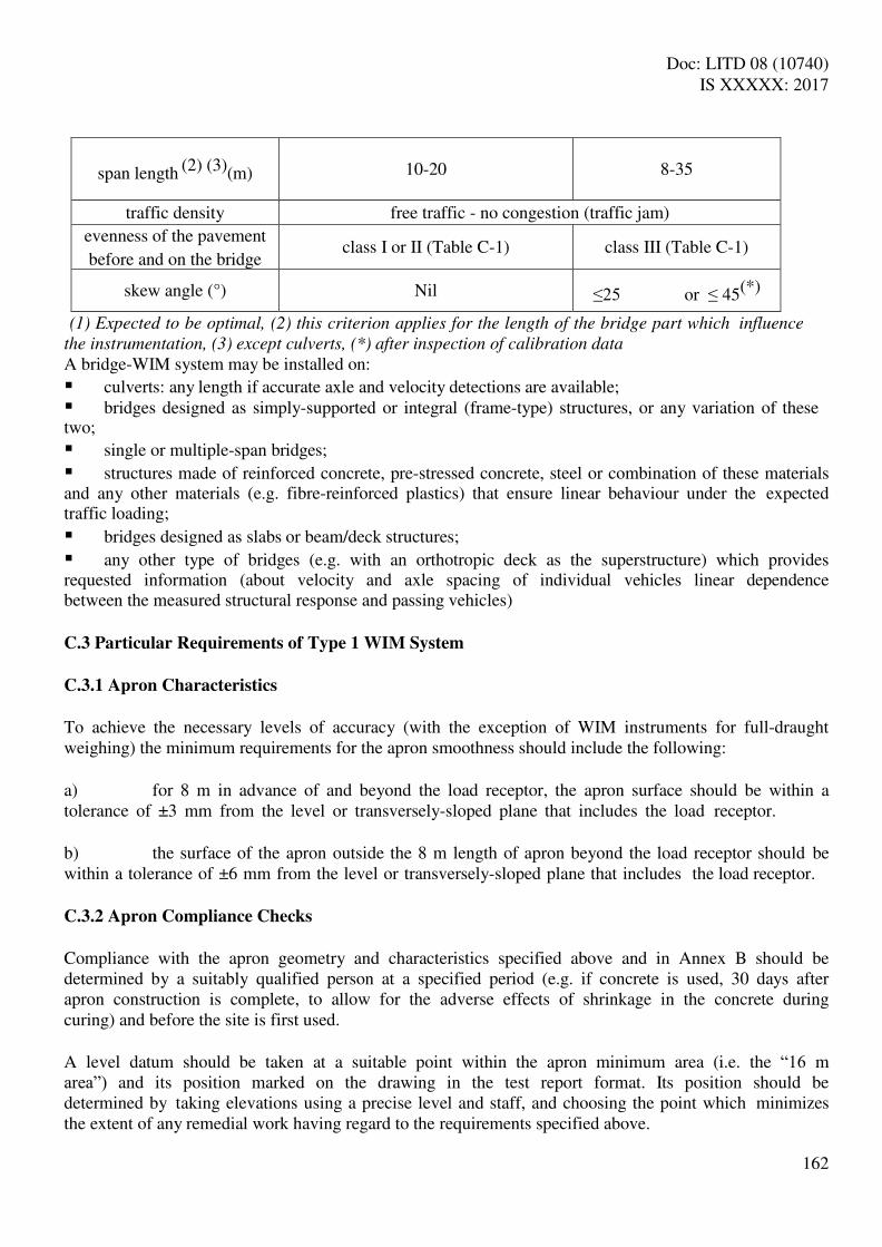
Doc: LITD 08 (10740) IS XXXXX: 2017
162
span length (2) (3)(m) 10-20 8-35
traffic density free traffic - no congestion (traffic jam)
evenness of the pavement
before and on the bridge class I or II (Table C-1) class III (Table C-1)
skew angle (°) Nil ≤25 or ≤ 45(*)
(1) Expected to be optimal, (2) this criterion applies for the length of the bridge part which influence
the instrumentation, (3) except culverts, (*) after inspection of calibration data A bridge-WIM system may be installed on:
culverts: any length if accurate axle and velocity detections are available; bridges designed as simply-supported or integral (frame-type) structures, or any variation of these two;
single or multiple-span bridges;
structures made of reinforced concrete, pre-stressed concrete, steel or combination of these materials and any other materials (e.g. fibre-reinforced plastics) that ensure linear behaviour under the expected traffic loading;
bridges designed as slabs or beam/deck structures;
any other type of bridges (e.g. with an orthotropic deck as the superstructure) which provides requested information (about velocity and axle spacing of individual vehicles linear dependence between the measured structural response and passing vehicles) C.3 Particular Requirements of Type 1 WIM System
C.3.1 Apron Characteristics
To achieve the necessary levels of accuracy (with the exception of WIM instruments for full-draught weighing) the minimum requirements for the apron smoothness should include the following: a) for 8 m in advance of and beyond the load receptor, the apron surface should be within a tolerance of ±3 mm from the level or transversely-sloped plane that includes the load receptor. b) the surface of the apron outside the 8 m length of apron beyond the load receptor should be within a tolerance of ±6 mm from the level or transversely-sloped plane that includes the load receptor. C.3.2 Apron Compliance Checks
Compliance with the apron geometry and characteristics specified above and in Annex B should be determined by a suitably qualified person at a specified period (e.g. if concrete is used, 30 days after apron construction is complete, to allow for the adverse effects of shrinkage in the concrete during curing) and before the site is first used. A level datum should be taken at a suitable point within the apron minimum area (i.e. the “16 m area”) and its position marked on the drawing in the test report format. Its position should be determined by taking elevations using a precise level and staff, and choosing the point which minimizes the extent of any remedial work having regard to the requirements specified above.

Doc: LITD 08 (10740) IS XXXXX: 2017
163
A 400 mm X 400 mm (normal) grid of level control points should be marked out durably on the aprons for 8 m either side of the load receptors(s). A 1 m X 1 m (nominal) grid of level control points should be marked out on the remainder of the aprons. Setting out lines for the control points should be shown on the drawing in the test report format. Elevations should be taken on all those points using the precise level and staff. If concrete is used, a simple stability check should be undertaken to monitor any changes in apron elevation under an axle load. A loaded two-axle vehicle, with a rear axle loading as near to the maximum capacity of the WIM instrument as feasible, should pass at a low speed along the approximate lateral center of the concrete aprons. Elevations should be taken at the corners of each stab making up the apron at each transverse joint to ensure that as the vehicle crosses the joint, no movement in elevation is outside the tolerances specified in See 3.1. C.4. Operational Requirements
C.4.1 Routine Durability Checks
Surface level compliance checks should be repeated using the same level control points at time intervals specified by national legislation. (Note : There are a number of factors (e.g. level of usage, construction of aprons, etc.) which should be
taken into consideration when specifying the time interval between compliance checks.)
C.4.2 Split Material
Care should be taken in the design and operation of the installation to ensure that, as far as possible, a build-up of spilt material on the weigh zone of the system either does not occur, or is removed regularly. C.4.3 Overhead Structures
Load receptors should not be installed beneath a loading or conveying mechanism from which loose material might fall. C.4.4 Tare Weighing
The time between tare weighing and gross weighing operations associated with a particular load should be minimal. C.4.5 Notice of Speed Restrictions
There should be means to ensure that all drivers of vehicles that cross the load receptor(s) are aware of the minimum and maximum operating speeds at which they can proceed. C.4.6 Lightning Arrestors
Lightning arrestors shall be checked regularly at intervals not more than six months to ensure continued operations.

Doc: LITD 08 (10740) IS XXXXX: 2017
164
Annex D
(Informative) General Guidelines for the Calibration of Weigh-In-Motion Systems
D.1 General
The manufacturer or the vendor shall specify the detailed procedure and methods for calibration to ensure to ensure that the WIM system performs properly during the site design life. The guidelines given herein may be used to supplement that information only. After installation/re-installation and general checking, an initial calibration shall be performed for acceptance testing. Recalibration (fine tuning) shall be carried out throughout the design life of a WIM site to adjust parameters when problems are identified during the Quality Assurance Procedure for WIM data. Recalibration is called for following any relocation, significant modification of the WIM system, or significant change in site conditions. Unless otherwise agreed between the user and the vendor, calibration prior to acceptance of the system shall be the responsibility of the vendor and calibration after acceptance of the system shall be the responsibility of the user. The purpose of the WIM system and its application should guide the selection of a calibration procedure and method. The reference values used for calibration must be chosen accordingly. D.2 Reference Values
If the WIM data are used to estimate vehicle mass and static reference axle-loads for two-axle rigid vehicles, it is required to minimise the differences (bias) between indicated value of data item and reference value of data item. Therefore, the reference values should be vehicle mass or static reference axle loads for two-axle rigid vehicles (or both) or corrected mean axle loads or corrected mean wheel loads to provide traceability. The accuracy of these reference values should be appropriate for the expected accuracy of the WIM system to be calibrated. If the WIM data are used to provide instantaneous impact forces, the reference values should be the “true” impact forces applied by the wheels or axles when they hit the WIM sensors. D.3 Calibration Checks
The accuracy of an operational WIM system shall be checked regularly, e.g., once or twice a year (in- service inspection, clause 9.3.2, or accuracy check, clause A.11). For a newly installed WIM system, some check(s) (clause A.11) shall be carried out during the first three month period of use. Calibration checks may be carried out using the same methods as for an initial calibration (clause 9.2), but with fewer reference values or test vehicles and runs. D.4 Calibration Methods
The calibration methods briefly described herein are based on COST 323 (see 2.5) recommendations which are retained in the Draft European Specification (see 2.6), and are most commonly used, from the simplest to the most sophisticated. Other calibration methods may also be considered including those
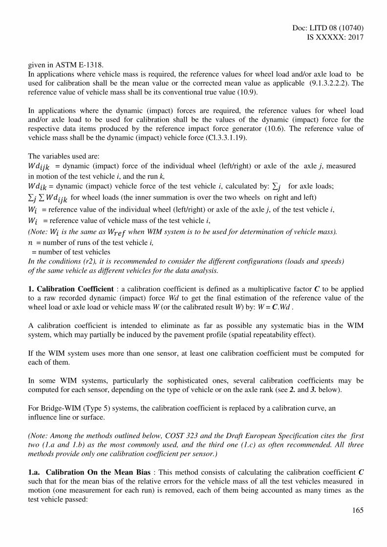
Doc: LITD 08 (10740) IS XXXXX: 2017
165
given in ASTM E-1318. In applications where vehicle mass is required, the reference values for wheel load and/or axle load to be used for calibration shall be the mean value or the corrected mean value as applicable (9.1.3.2.2.2). The reference value of vehicle mass shall be its conventional true value (10.9). In applications where the dynamic (impact) forces are required, the reference values for wheel load and/or axle load to be used for calibration shall be the values of the dynamic (impact) force for the respective data items produced by the reference impact force generator (10.6). The reference value of vehicle mass shall be the dynamic (impact) vehicle force (Cl.3.3.1.19). The variables used are: 𝑊 = dynamic (impact) force of the individual wheel (left/right) or axle of the axle j, measured
in motion of the test vehicle i, and the run k, 𝑊 = dynamic (impact) vehicle force of the test vehicle i, calculated by: ∑ for axle loads;
∑ ∑ 𝑊 for wheel loads (the inner summation is over the two wheels on right and left) 𝑊 = reference value of the individual wheel (left/right) or axle of the axle j, of the test vehicle i, 𝑊 = reference value of vehicle mass of the test vehicle i,
(Note: 𝑊 is the same as 𝑊 when WIM system is to be used for determination of vehicle mass).
= number of runs of the test vehicle i, = number of test vehicles In the conditions (r2), it is recommended to consider the different configurations (loads and speeds) of the same vehicle as different vehicles for the data analysis.
1. Calibration Coefficient : a calibration coefficient is defined as a multiplicative factor C to be applied to a raw recorded dynamic (impact) force Wd to get the final estimation of the reference value of the wheel load or axle load or vehicle mass W (or the calibrated result W) by: W = C.Wd . A calibration coefficient is intended to eliminate as far as possible any systematic bias in the WIM system, which may partially be induced by the pavement profile (spatial repeatability effect). If the WIM system uses more than one sensor, at least one calibration coefficient must be computed for each of them. In some WIM systems, particularly the sophisticated ones, several calibration coefficients may be computed for each sensor, depending on the type of vehicle or on the axle rank (see 2. and 3. below). For Bridge-WIM (Type 5) systems, the calibration coefficient is replaced by a calibration curve, an influence line or surface. (Note: Among the methods outlined below, COST 323 and the Draft European Specification cites the first
two (1.a and 1.b) as the most commonly used, and the third one (1.c) as often recommended. All three
methods provide only one calibration coefficient per sensor.)
1.a. Calibration On the Mean Bias : This method consists of calculating the calibration coefficient C such that for the mean bias of the relative errors for the vehicle mass of all the test vehicles measured in motion (one measurement for each run) is removed, each of them being accounted as many times as the test vehicle passed:

Doc: LITD 08 (10740) IS XXXXX: 2017
166
𝐶 = ∑∑ , 𝑊𝑊 ……………………..(32)
This method provides an unbiased estimator of the vehicle mass appropriate for vehicle sample Condition (r1). 1.b. Calibration On the Total Vehicle Mass: This method consists of calculating the calibration coefficient C as the ratio of the total reference value of vehicle mass of all the test vehicles (each of Them being accounted for as many times as the test vehicle) to the total vehicle mass of these vehicles measured in motion (one measurement for each run): 𝐶 = ∑ 𝑊∑ , 𝑊 ……………………….……(33)
This method provides an unbiased estimator of the total weight of all the vehicles. It is only appropriate if the purpose of the WIM system is the estimation of the whole traffic tonnage, such as in economical surveys of goods transportation like in the case of Type 4 WIM systems. 1.c. Calibration On the Mean Square Error (1) : This method consists of calculating the slope of a regression line which passes through the origin in an orthonormal diagram plotting the individual dynamic (impact) vehicle force versus the individual reference value of vehicle mass of the test vehicles for each passage. It is based on the fact that a WIM system should provide dynamic (impact) loads which are proportional to the reference loads. The calibration coefficient C is given by: 𝐶 = ∑ 𝑊∑ , 𝑊 𝑊 ……………………………………….(34)
This method may be applied for conditions (r2) to (R2), with more than 3 test vehicles (or loading cases); it minimises the mean square error of the individual vehicle mass measurements with respect to the reference value of vehicle mass for all the vehicles passed, with the constraint that the dynamic (impact) vehicle force are proportional to the reference value of vehicle mass. It is appropriate for most applications, when the purpose is the estimation of the individual vehicle masses, because the estimator has a lower variance than the two previous ones and a very small bias. 1.d. Calibration On the Mean Square Error (2) : This method consists of calculating the slope and the ordinate at the origin of the regression line in an orthonormal diagram plotting the individual dynamic (impact) vehicle force versus the individual reference value of vehicle mass of the test vehicles for each passage. The mean square error should be smaller than with the previous method, but the proportionality between the dynamic (impact) loads and the reference loads is no longer ensured, which is not in accordance with theory. The calibration procedure becomes: W = C.(Wd - b), with C and b
given by : 𝐶 = ∑ ∑ 𝑊 − ∑ 𝑊∑ (∑ 𝑊 𝑊, )− ∑ 𝑊 (∑ 𝑊, )………………………..(35)
b = (∑ 𝑊 )(∑ 𝑊, )− ∑ 𝑊 (∑ 𝑊 𝑊, )∑ (∑ 𝑊 )− ∑ 𝑊 ……………………..(36)

Doc: LITD 08 (10740) IS XXXXX: 2017
167
This method is not considered appropriate in most cases because of the theoretical inconsistency explained above. It may be applied, if the b value is rather small and independent of the calibration vehicle sample considered. (Note: In both methods 1.c. and 1.d., the vehicle mass may be replaced by the axle loads and the
formulas adapted. The calibration coefficients shall then be slightly different. The reliability of
results will be less, because the individual axle loads are more significantly affected by the dynamic
motion of the vehicles than the vehicle mass, and because the static reference axle loads are not well
defined for vehicles other than two-axle rigid vehicle.)
2. Calibration by Vehicle Type or Vehicle Class: This method provides one calibration coefficient for each type of vehicle (Table 5) from the test sample, or for each class of vehicle (based on axle arrangement). It is only applicable for conditions (R1) and (R2), and of interest if the WIM station software is able to manage such a set of calibration coefficients according to each vehicle type. The same formulas as in 1.a. to 1.d may be applied, as many times as the number of vehicle classes considered. The same remarks apply to each formula and procedure. 3. Calibration by Axle Rank and Type: This method provides one calibration coefficient for each rank (and/or type) of axle within a vehicle, taking into account the fact that the axle dynamic behaviour depends on their rank and type in the vehicle. Axle-group shall be calibrated by considering axle- group load. In the absence of criteria for identifying axle-group, individual axles of axle-group will be calibrated as single axle. It is only of interest if the WIM station software is able to manage such a set of calibration coefficients according to each axle rank and type. The following sub-populations may be considered, some of which may be merged for simplification:
for the 2-axle rigid vehicle: the front axles and the rear axles, for the 3-axle rigid vehicle: the front axles and the rear tandem axle (sum of the two rear axles). for semi-articulated vehicles: the front axles, the drive axles and the tandem or tridem axles of the semi-trailer (sum of the two or three rear axles) for truck-trailer combination: the front axles, the rear axles (or tandem or tridem) of the truck, the axles of the trailers The formulas given above are again applied to each sub-population by replacing the vehicle mass by the axle loads. The same remarks apply to each formula and procedure. (Note: Except for bridge WIM (Type 5), all of these calibration methods are more efficient in cases (R1)
and (R2) with a test vehicle sample being representative of the expected traffic flow. In the case of (r1) or
(r2) it is appropriate to choose loads (vehicle mass and axle loads) which are representative of the
load distribution encountered for the same type of vehicles as the test vehicle in the traffic flow.)
4. Automatic Self-Calibration: This is a software based method which involves fitting some statistics recorded and computed by the WIM system to some target values depending on the site-specific traffic. The procedure requires a good prior knowledge of the site specific traffic composition and statistics of the axle and vehicle loads. The automatic calibration system is specific to its lane. So in case of more than one instrumented lane, the traffic on each lane should be taken into account separately.
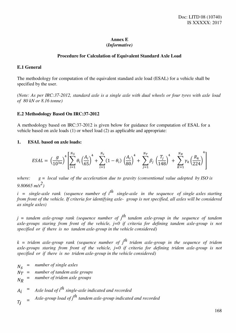
Doc: LITD 08 (10740) IS XXXXX: 2017
168
Annex E
(Informative)
Procedure for Calculation of Equivalent Standard Axle Load
E.1 General
The methodology for computation of the equivalent standard axle load (ESAL) for a vehicle shall be specified by the user. (Note: As per IRC:37-2012, standard axle is a single axle with dual wheels or four tyres with axle load
of 80 kN or 8.16 tonne)
E.2 Methodology Based On IRC:37-2012
A methodology based on IRC:37-2012 is given below for guidance for computation of ESAL for a vehicle based on axle loads (1) or wheel load (2) as applicable and appropriate: 1. ESAL based on axle loads:
𝐸 𝐴𝐿 = 𝑎 [∑ 𝜃 (𝐴 ) + ∑ − 𝜃 (𝐴8 ) + ∑ ( 8) + ∑ ( )𝑁=
𝑁=
𝑁=
𝑁= ]
where: g = local value of the acceleration due to gravity (conventional value adopted by ISO is
9.80665 m/s2)
i = single-axle rank (sequence number of ith
single-axle in the sequence of single axles starting
from front of the vehicle. If criteria for identifying axle- group is not specified, all axles will be considered
as single axles)
j = tandem axle-group rank (sequence number of jth
tandem axle-group in the sequence of tandem
axle-groups staring from front of the vehicle, j=0 if criteria for defining tandem axle-group is not
specified or if there is no tandem axle-group in the vehicle considered)
k = tridem axle-group rank (sequence number of jth
tridem axle-group in the sequence of tridem
axle-groups staring from front of the vehicle, j=0 if criteria for defining tridem axle-group is not
specified or if there is no tridem axle-group in the vehicle considered) 𝑁 = number of single axles 𝑁 = number of tandem axle groups 𝑁 𝐴
=
=
=
number of tridem axle groups
Axle load of ith
single-axle indicated and recorded
Axle-group load of jth
tandem axle-group indicated and recorded

Doc: LITD 08 (10740) IS XXXXX: 2017
169
= Axle-group load of k
th tridem axle-group indicated and recorded
𝑎 = Measurement unit factor for axle-load, axle-group load and wheel-load (𝑎 =1 if the unit is kilogram, 𝑎 =0 if the unit is tonne) 𝜃 = Tyre factor for single axle (𝜃 =1 for two-tyre single axles, 𝜃 =0 for four-tyre single axles)
= Tyre factor for tandem axle-group ( =0 for tandem axle-groups with two-tyre axles, =1 for
tandem axle-groups with four-tyre axles)
k = Tyre factor for tridem axle-group ( =0 for tridem axle-groups with two-tyre axles, =1 for
tridem axle-groups with four-tyre axles)
2. ESAL based on wheel loads:
ESAL based on wheel loads can be computed by using any of the two methods specified below: 2.1. ESAL based on wheel loads can be computed by using the following formula –
𝐸 𝐴𝐿 = 𝑎 [∑ 𝜃 (𝐿 + )𝑁
=+ ∑ − 𝜃 (𝐿 +8 )𝑁=+ ∑ ∑ 𝐿 + ∑ == 8 + ∑ ∑ 𝐿 + ∑ ==𝑁
=𝑁= ]
where:
𝐿1 = Left hand side wheel load of ith single-axle indicated and recorded
1 = Right hand side wheel load of ith single-axle indicated and recorded 𝐿2 r= Left hand side wheel load of rth individual axle of the jth tandem axle-group, indicated and recorded
2 r= Right hand side wheel load of rth individual axle of the jth tandem axle-group, indicated and recorded 𝐿3kr= Left hand side wheel load of rth individual axle of the jth tridem axle-group, indicated and recorded
3 r= Right hand side wheel load of rth individual axle of the jth tridem axle-group, indicated and
recorded
All other symbols have the same meaning as stated in equation 1 (ESAL based on axle loads)
2.2. ESAL based on wheel loads can be also be computed by using the following formula – 𝐸 𝐴𝐿 = 𝑎 [∑ {(𝐿 + ) + (𝐿 +8 ) }𝑁
=+ ∑ ∑ 𝐿 + ∑ == 8 + ∑ ∑ 𝐿 + ∑ ==𝑁=
𝑁= ]

Doc: LITD 08 (10740) IS XXXXX: 2017
170
𝐿1 = Left hand side wheel load (single-tyre) on the ith single axle with two tyres (single tyre wheel on
either side) indicated and recorded, otherwise zero
1 = Right hand side single wheel load (single-tyre) on the ith single axle with two tyres (single tyre wheel
on either side) indicated and recorded, otherwise “zero” 𝐿2 =Left hand side wheel load (dual-tyre) on the ith
single axle with four tyres (dual tyre wheel on either
side) indicated and recorded, otherwise “zero”
2 = Right hand side wheel load (dual-tyre) on the ith
single axle with four tyres (dual tyre wheel on
either side) indicated and recorded, otherwise “zero” 𝐿2 = Left hand side wheel load (dual-tyre) of r
th individual axle with four tyres (dual tyre wheel on
either side) of the jth
tandem axle-group, indicated and recorded, otherwise “zero”
2 = Right hand side wheel load (dual-tyre) of rth
individual axle with four tyres (dual tyre wheel on
either side) of the jth
tandem axle-group, indicated and recorded, otherwise “zero”
𝐿3 = Left hand side wheel load (dual-tyre) of rth
individual axle with four tyres (dual tyre wheel on
either side) of the kth
tridem axle-group, indicated and recorded, otherwise “zero”
3 = Right hand side wheel load (dual-tyre) of rth
individual axle with four tyres (dual tyre wheel on
either side) of the kth
tridem axle-group, indicated and recorded, otherwise “zero”
All other symbols have the same meaning as stated in equation 1 (ESAL based on axle loads)
(Note: If the formula shown in 2.2 is to be used, all possible wheel load values shall have to be
initialized to “zero” before start of data collection session for each identified vehicle)

Doc: LITD 08 (10740) IS XXXXX: 2017
171
ANNEX-F
(Normative) (Clause 2) List of References
1. Legal Metrology (General) Rules, 2011, Seventh Schedule-Heading-A: Specifications for Non-automatic weighing instruments.
2. OIML R 134-1:2006: International Recommendation for Automatic instruments for weighing road vehicles in motion and measuring axle loads, Part-1: Metrological and technical requirements – Tests; published by the Organisation Internationale De Métrolie Légale (OIML).
3. OIML R 134-2:2009: International Recommendation for Automatic instruments for weighing road vehicles in motion and measuring axle loads, Part-2: Test Report Format; published by the Organisation Internationale De Métrolie Légale (OIML).
4. ASTM E 1318-09: Standard Specification for Highway Weigh-In-Motion (WIM) Systems with User Requirements and Test Methods; published by American Society for Testing and Materials (ASTM International).
5. COST 323 “Weigh-in-Motion of Road Vehicles” Final Report (1993-1998) Appendix-1: European WIM Specification.
6. Draft European Standard pr EN (NN nnnnn) Version 2010/1: Weigh-in-Motion of Road Vehicles developed by the Federation of European Highway Research Laboratories WIM initiative (FiWi) and available as draft standard DIN 8113.
7. Measure of a General Nature No. 0111-OOP-C010-10 (reference no. 0313/003/10/Pos., publication date: 21 May 2010) issued by the Czech Metrology Institute: Stipulating metrological and technical requirements for specified measuring devices, including test methods for verifying specified measuring devices: "high-speed weigh-in-motion road vehicle scales".
8. IRC:3-1983: Dimensions and Weights of Road Design Vehicles, published by the Indian Roads Congress (http://www.irc.org.in).
9. IRC:37-2012: Tentative Guidelines for the Design of Flexible Pavements, published by the Indian Roads Congress (http://www.irc.org.in
10. IS: 9281-1979 (Reaffirmed 2008): Indian Standard Specification for Electronic Weighing Systems, published by the Bureau of Indian Standards (http://www.bis.org.in/).
11. IS: 9000 (Part 2) : Basic environmental testing procedures for electronic and electrical items: Part 2 Cold test
12. IS: 9000 (Part 3) : Basic environmental testing procedures for electronic and electrical items: Part 3 Dry heat test
13. IS: 9000 (Part 4): Basic environmental testing procedures for electronic and electrical items: Part 4 Damp heat (steady state) (First Revision)
14. IS 9000 (Part 7/ Sec 2) : Basic environmental testing procedures for electronic and electrical items: Part 7 Impact test, Sec 2 Bump
15. IS 9000 (Part 12) : Basic environmental testing procedures for electronic and electrical items: Part 12 Dust test
16. IS 9000 (Part 16) : Basic environmental testing procedures for electronic and electrical items: Part 16 Driving rain test
17. IS: 14700 (Part 4/Sec2) : Electromagnetic compatibility (EMC) : Part 4 Testing and measurement techniques, Sec 2 Electrostatic discharge immunity test
18. IS: 14700 (Part 4/Sec 3) : Electromagnetic compatibility (EMC) : Part 4 Testing and measurement techniques, Sec 3 Radiated, radio- frequency, electromagnetic field immunity test
19. IS: 14700 (Part 4/Sec 4) : Electromagnetic compatibility (EMC) : Part 4 Testing and measurement techniques, Sec 4 Electrical Fast Transient/Burst Immunity Test
20. IS: 14700 (Part 4/Sec 5) : Electromagnetic compatibility (EMC) : Part 4 Testing and measurement techniques, Sec 5 Surge immunity test

Doc: LITD 08 (10740) IS XXXXX: 2017
172
21. IS: 14700 (Part 4/Sec 11) : Electromagnetic compatibility (EMC) : Part 4 Testing and measurement techniques, Sec 11 Voltage dips, short interruptions and voltage variations immunity tests
22. IEC 60068-2-47 Ed 3.0 (2005-4) : Environmental testing – Part 2: Test methods – Section 47: Mounting of specimens for vibration, impact and similar dynamic tests Stability date: 2014
23. IEC 60068-2-64 Ed 2.0 (2008-04) Environmental testing – Part 2: Test methods – Section 64: Test Fh: Vibration, broad- band random and guidance
24. IEC 60512-11-8 Ed. 1.0 (1995-11) Electromechanical components for electronic equipment – Basic testing procedures and measuring methods – Part 11: Climatic tests –Section 8: Test 11h – Sand and dust
25. IEC 60721-2-5 Ed. 1.0 (1991-07) Classification of environmental conditions – Part 2: Environmental conditions appearing in nature – Section 5: Dust, sand, salt mist
26. IEC 60068-2-18 Ed. 2.0 (2000-10) Environmental testing – Part 2: Test methods – Section 18: Test R and guidance: Water
27. IEC 60512-14-7 Ed. 1.0 (1997-10) Electromechanical components for electronic equipment – Basic testing procedures and measuring methods – Part 14: Sealing tests – Section 7: Test 14g: Impacting water
28. IEC 61000-2-1 (1990-05) Electromagnetic compatibility (EMC) Part 2: Environment Section 1
29. IEC 60654-2 (1979-01), with amendment 1 (1992-09) Operating conditions for industrial- process measurement and control equipment - Part 2: Power
30. IEC 61000-4-11 (2004-03) Electromagnetic compatibility (EMC) Part 4-11: Testing and measuring techniques - Voltage dips, short interruptions and voltage variations immunity tests
31. IEC 61000-4-4 (2004-07) Electromagnetic compatibility (EMC) Part 4-4: Testing and measurement techniques - Electrical fast transient/burst immunity test
32. IEC 61000-4-5 (2001-04) consolidated edition 1.1 (Including Amendment 1 and Correction 1) Electromagnetic compatibility (EMC)- Part 4-5: Testing and measurement techniques - Surge immunity test
33. IEC 61000-4-2 (1995-01) with amendment 1 (1998-01) and amendment 2 (2000-11) Consolidated Edition: IEC 61000- 4-2 (2001-04) Ed. 1.2 Basic EMC Publication. Electromagnetic Compatibility (EMC) - Part 4: Testing and measurement techniques - Section 2: Electrostatic discharge immunity test. Basic EMC Publication
34. IEC 61000-4-3 Consolidated Edition 2.1 (including amendment 1) (2002-09) Electromagnetic Compatibility (EMC) - Part 4: Testing and measurement techniques - Section 3: Radiated, radio- frequency,
35. IEC 61000-4-6 (2003-05) with Amendment 1 (2004-10) Electromagnetic compatibility (EMC) Part 4: Testing and measurement techniques. Section 6: Immunity to conducted disturbances, induced by radio-frequency fields
36. ISO 7637-3 (1995) with correction 1 (1995) Road vehicles - Electrical disturbance by conduction and coupling - Part 3: Passenger cars and light commercial vehicles with nominal 12 V supply voltage and commercial vehicles with 24 V supply voltage - electrical transient transmission by capacitive and inductive coupling via lines other than supply lines
37. ISO 7637-2 (2004) Road vehicles - Electrical disturbance by conduction and coupling - Part 2: Electrical transient conduction along supply lines only
38. ISO 16750-2 (2003) Road vehicles - Environmental conditions and testing for electrical and electronic equipment - Part 2: Electrical loads
39. IS 9001 (Part 12) Guidance on method of mounting of electronic and electrical items for dynamic tests
40. IEC 60529 Ed. 2.1 (2001-02) Degrees of protection provided by enclosures (IP Code) Corr.1 (2003-01) Ed. 2.1 Corr.2 (2007-10) Ed. 2.1

Doc: LITD 08 (10740) IS XXXXX: 2017
173
Bibliography
Ref. Standards and reference documents Description
[1] International Vocabulary of Basic and General Terms in Metrology (VIM) (1993)
Vocabulary, prepared by a joint working group consisting of experts appointed by BIPM, IEC, IFCC, ISO, IUPAC, IUPAP and OIML.
[2] International Vocabulary of Terms in Legal Metrology, OIML, Paris (2000)
Vocabulary including only the concepts used in the field of legal metrology. These concepts concern the activities of the legal metrology service, the relevant documents as well as other problems linked with this activity. Also included in this Vocabulary are certain concepts of a general character which have been drawn from the VIM.
[3] OIML B 3 (2003) OIML Certificate System for Measuring Instruments (formerly OIML P 1)
Provides rules for issuing, registering and using OIML Certificates of conformity.
[4] OIML D 11 (2004) General requirements for electronic measuring instruments
Contains general requirements for electronic measuring instruments.
[5] OIML R 111 (2004) Weights of classes E1, E2, F1, F2, M1, M1-2, M2, M2-3 and M3
Provides the principal physical characteristics and metrological requirements for weights used with and for the verification of weighing instruments and weights of a lower class.
[6] OIML D 28 (2004) Conventional value of the result of weighing in air
Provides the definition of the quantity “conventional mass” (conventional value of the result of weighing in air) as it is used for the characterization of weights and its relation to the physical quantities mass and density and the evaluation of its uncertainty.
[7] OIML R 60 (2000) Metrological regulation for load cells
Provides the principal static characteristics and static evaluation procedures for load cells used in the evaluation of mass.
[8] Jacob, B. (2000): Assessment of the Accuracy and Classification of Weigh- in-Motion Systems: Part 1 Statistical Background
International Journal of Vehicle Design - Heavy Vehicle Systems, Vol. 7, Nos. 2/3, 2000
[9] IEC 60068-2-1 (1990-05) with amendments 1 (1993-02) and 2 (1994- 06) Environmental testing, Part 2: Tests, Test A: Cold
Concerns cold tests on both non heat dissipating and heat dissipating equipment under test (EUT).

Doc: LITD 08 (10740) IS XXXXX: 2017
174
[10] IEC 60068-2-2 (1974-01) with amendments 1 (1993-02) and 2 (1994- 05) Environmental testing Part 2: Tests, Test B: Dry heat
Contains test Ba: dry heat for non- heat dissipating specimen with sudden change of temperature; test Bb: dry heat for non- heat dissipating specimen with gradual change of temperature; tests Bc: dry heat for heat dissipating specimen with sudden change of temperature; test Bd dry heat for heat dissipating specimen with gradual change of temperature. The 1987 reprint includes IEC No. 62-2-2A.
[11] IEC 60068-3-1 (1974-01) + Supplement A (1978-01): Environmental testing Part 3 Background information, Section 1: Cold and dry heat tests
Gives background information for Tests A: Cold (IEC 68-2-1), and Tests B: Dry heat (IEC 68-2-2). Includes appendices on the effect of: chamber size on the surface temperature of a specimen when no forced air circulation is used; airflow on chamber conditions and on surface temperatures of test specimens; wire termination dimensions and material on surface temperature of a component; measurements of temperature, air velocity and emission coefficient. Supplement A gives additional information for cases where temperature stability is not achieved during the test.
[12] IEC 60068-2-78 (2001-08) Environmental testing - Part 2-78: Tests - Test Cab: Damp heat, steady state (IEC 60068-2-78 replaces the following withdrawn standards: IEC 60068-2-3, test Ca and IEC 60068-2-56, test Cb)
Provides a test method for determining the suitability of electro-technical products, components or equipment for transportation, storage and use under conditions of high humidity. The test is primarily intended to permit the observation of the effect of high humidity at constant temperature without condensation on the specimen over a prescribed period. This test provides a number of preferred severities of high temperature, high humidity and test duration. The test can be applied to both heat-dissipating and non-heat dissipating specimens. The test is applicable to small equipment or components as well as large equipment having complex interconnections with test equipment external to the chamber, requiring a setup time which prevents the use of preheating and the maintenance of specified conditions during the installation period.

Doc: LITD 08 (10740) IS XXXXX: 2017
175
[13] IEC 60068-3-4 (2001-08) Environmental testing - Part 3-4: Supporting documentation and guidance -Damp heat tests
Provides the necessary information to assist in preparing relevant specifications, such as standards for components or equipment, in order to select appropriate tests and test severities for specific products and, in some cases, specific types of application. The object of damp heat tests is to determine the ability of products to withstand the stresses occurring in a high relative humidity environment, with or without condensation, and with special regard to variations of electrical and mechanical characteristics. Damp heat tests may also be utilized to check the resistance of a specimen to some forms of corrosion attack.
[14] IEC 60068-3-8 Ed. 1.0 (2003-08) Environmental testing – Part 3: Supporting documentation and guidance –Section 8: Selecting amongst vibration tests
Provides guidance for selecting amongst the IEC 60068-2 stationary vibration test methods Fc sinusoidal, Fh random and F(x) Mixed mode vibration. The different steady-state test methods and their aims are briefly described in Clause 4. Transient test methods are not included. For vibration testing, the environmental conditions, especially the dynamic conditions for the specimen, should be known. This standard helps to collect information about the environmental conditions (Clause 5), to estimate or measure the dynamic conditions (Clause 6) and gives examples to enable decisions to be made on the most applicable environmental vibration test method. Starting from the condition, the method of selecting the appropriate test is given. Since real life vibration conditions are dominated by vibration of a random nature, random testing should be the commonly used method, see Table 1, Clause 7. The methods included hereafter may be used to examine the vibration response of a specimen under test before, during and after vibration testing. The selection for the appropriate excitation method is described in Clause 8 and tabulated in Table 2. In this standard specification, writers will find information concerning vibration test methods and guidance for their selection.

Doc: LITD 08 (10740) IS XXXXX: 2017
176
[15] IEC 60529 Ed. 2.1 (2001-02) Degrees of protection provided by enclosures (IP Code) Corr.1 (2003-01) Ed. 2.1 Corr.2 (2007-10) Ed. 2.1
Applies to the classification of degrees of protection provided by enclosures for electrical equipment with a rated voltage not exceeding 72.5 kV.


![IS 8909-2 (1978): Fixed Resistors, General Purpose, Power ...Part 2: Type FRP1 [LITD 5: Semiconductor and Other Electronic Components and Devices] UDC 621’316’8 : 621’38/‘39’038](https://img.pdfslide.us/doc/110x75/61290345e018fc332a482673/is-8909-2-1978-fixed-resistors-general-purpose-power-part-2-type-frp1.jpg)