Embed Size (px)
Citation preview
Wide-angle narrow-bandpass optical detection systemoptimally designed to have a large signal-to-noise ratio
Naftali Schweitzer and Yoel Arieli
A method for achieving optimal design of a wide-angle narrow-bandpass optical detection system com-posed of a spherical interference filter and a circular photodetector is introduced. It was found that thereis an optimal photodetector diameter that maximizes the signal-to-noise ratio ~SNR! for a given filterconfiguration. We show how to optimize optical detection systems based on spherical interference filtersfor all the important parameters simultaneously. The SNR values of these systems are compared withthe SNR values of spherical-step-filter-based detection systems. When large silicon photodetectors areused, the two systems have equal SNR values so that the more economical step-filter systems arepreferable. The results given here in the near-infrared region can be used for the optimization of anyconfiguration of a detection system based on a spherical interference filter and a silicon photodetectorworking at the same wavelength range, without further calculations. © 2000 Optical Society of America
OCIS codes: 040.0040, 040.1880, 120.2440.
1
1. IntroductionDetection systems used in atmospheric and outer-space laser communications are usually made up ofbroadband photodetectors, since narrow-band opticalsensors hardly exist. In such applications most ofthe noise for a well-designed receiver is white noisecaused by solar background radiation. Narrow-bandpass optical interference filters or wide-bandpass optical step filters are generally used tofilter out this unwanted background radiation. In-terference filters in the visible and the near-infraredregions typically have spectral bandwidths of 10 nmand 50% peak transmission. A laser diode with atypical bandwidth of several nanometers and a pho-todetector with a matching interference filter may bethe basis for an efficient communication system witha high signal-to-noise ratio ~SNR!. However, themain disadvantage of interference filters is the de-crease of energy transmission through the filter withincreasing angles of incidence. In fact, at an angle ofincidence of ;30°, an interference filter ceases to
The authors are with the Department of Electro-Optics andApplied Physics, Jerusalem College of Technology, 21 HavaadHaleumi Street, P.O. Box 16031, Jerusalem 91160, Israel. Thee-mail address for N. Schweitzer is [email protected].
Received 10 May 1999; revised manuscript received 20 October1999.
0003-6935y00y060913-06$15.00y0© 2000 Optical Society of America
transmit the wavelength for which it was designed.Often, free-space optical communication systemsmust function even for angles of incidence as great as60°, so that, in these cases, interference filters areunsuitable.
Several authors2–5 have suggested solutions to theabove problem. These solutions were usually basedon using interference-filter optical systems thattransmit and concentrate the incident radiation per-pendicularly onto spherical surfaces on which thinfilms have been evaporated. Thus, at every point onthe surface of the interference filter, the angle ofincidence of the incident radiation is small, and theinterference filter is consequently highly transmis-sive. However, the above-mentioned systems aremade up of several optical components that are cum-bersome, difficult to align, and expensive. Also,their comparative heaviness is an argument againstintegrating them into airborne systems. Some ofthese systems are based on imaging so that largerdimensions are needed. Wide-field-of-view bire-fringence interference filters, composed of materi-als with large dispersion in birefringence near anisotropic point,6 do not seem to be in use today.The Faraday anomalous dispersion optical filter~FADOF! was recently reported7 to have a field ofview of 620°, which may not be enough. Conse-quently, the filters often used today in wide-field-of-view atmospheric communication systemsoperating in many spectral ranges are broadbandstep filters. For example, in the 750–1100-nm
20 February 2000 y Vol. 39, No. 6 y APPLIED OPTICS 913
wdb
aficitaadcpSTshwT
cisptgsrcdwfipg
9
spectral range, silicon photodetectors are often usedtogether with Schott RG-780 or RG-830 filters,which transmit ;90% of the radiation energy in a
ide spectral range. These systems have a seriousisadvantage in that the wide spectral band of theackground radiation ~usually sunlight! that they
transmit causes high shot noise, so that the all-important signal current-to-noise current ratio~SNR! is approximately three times less than theSNR obtained in receivers that comprise interfer-ence filters.
Recently, two wide-angle narrow-bandpass detec-tion systems, each based on a single transparentcomponent, were described. The transparent com-ponent is either a hemispherical lens8 or a glassdome.9 Spherical interference filters are achievedby evaporation of thin films of suitable materials ontothe spherical surfaces of these systems. The centersof the photodetectors coincide with the centers of thespheres that generate the spherical surfaces so thatthe radiation that reaches the photodetectors at anyangle hits the interference filters at relatively smallangles of incidence and suffers little attenuation.Thus the SNR is increased. The hemispherical lensconcentrates more incident radiation onto the index-matched photodetector surface, whereas the dome islighter and the filter can be constructed on the inter-nal spherical surface to protect it from mechanicalhazards during use.
The above systems must be carefully designed toproduce maximum SNR. No optimization has beenperformed on the dimension of the photodetector, andit is generally suggested that it be made as large aspossible.1 However, it is easy to see that such opti-mization exists. Assuming an electronically well-designed detector, the output signal current isproportional to the signal radiation flux, whereas therms shot-noise current is proportional to the squareroot of the background flux that hit the photodetector.Therefore the SNR is proportional to A1y2 where A isthe effective area of the photodetector, and one wouldexpect the SNR to increase with A. However, this istrue only with the use of step filters or plane inter-ference filters but is not true for spherical interfer-ence filters. Let us increase the area of a circularphotodetector for a fixed ~not too large! bandwidthnd a fixed radius of curvature of the interferencelter, beginning with zero. For small areas the in-oming radiation that hits the photodetector hits thenterference filter at small angles of incidence; sohere is little attenuation. However, when the di-meter of the photodetector is further increased, thettenuation increases, because larger angles of inci-ence in the filter are involved. The relative in-rease of the monochromatic signal ~laser! is lessronounced than that of the white noise ~Sun!; so theNR decreases at large photodetector diameters.his implies that an optimum diameter exists andhould be sought. Note that large-area detectorsave high capacitance, which can limit receiver band-idth and greatly increase receiver thermal noise.he goal is to develop a general method to design the
14 APPLIED OPTICS y Vol. 39, No. 6 y 20 February 2000
onstruction of an optimal detection system, takingnto account the possible optimization of the dimen-ion of the photodetector as well as all other relevantarameters. A detection system composed of an in-erference filter evaporated onto a hemisphericallass lens and a circular silicon photodetector de-igned to work outdoors in the near-infrared spectralegion will be described. The transmitter will beonsidered to be nearly monochromatic, i.e., a laseriode. The SNR obtained here will be comparedith the SNR of a detection system based on a steplter and a similar concentrating lens and siliconhotodetector to see which system is more advanta-eous.
2. Transmittance of Interference Filters at ObliqueIncidence
Bandpass interference filters are composed of a seriesof layers of precisely controlled thicknesses of dielec-trics and metals. Changing the angle of incidenceaffects both the apparent thickness of these layersand the reflectivity at the interfaces.10 The phasedifference between the interfering waves decreasesas the angle increases. The effects on off-normalradiation are threefold: There is a decrease in thecentral wavelength, the transmittance decreases,and the bandwidth increases. The decrease in cen-tral wavelength for collimated radiation incident atangle u, where u , 30°, is given approximately by11
lu 5 l0@1 2 ~n0yn*!2 sin2 u#1y2, (1)
where luq is the central wavelength at angle of inci-dence u, l0 is the central wavelength at normal inci-dence ~u 5 0!, n0 is the refractive index of the mediumsurrounding the filter, and n* is the effective refrac-tive index for the filter. For typical visible and near-infrared bandpass interference filters ~400–1100 nm!the experimental values of n* have been found to be;2.0 for high-index spacer layers and ;1.45 for low-index spacer layers. For off-normal angles of lessthan 30° the effects on transmittance and bandwidthare negligible.1,8
2. System Configuration
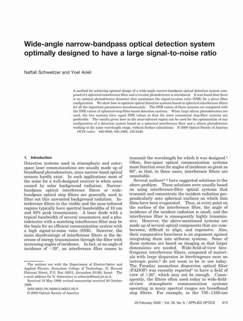
Figure 1 shows the glass hemisphere with the inter-ference filter and the index-matched photodetector.The beams reaching the filter can be considered col-limated because of the typically large distances be-tween the radiation sources and the detectionsystem. R is the radius of curvature of the sphericalfilter, r is the radius of the circular photodetector, anda is the angle between the radiation source and theoptical axis of the detection system. Note that thedistribution of the angles of incidence at the filterdepends on a. Assume that a 5 0 for the solar ra-diation ~worst case!. um, u9m are the maximum an-gles of incidence and refraction, respectively, for therays that hit the photodetector and are not dependent
wT
stnasttsofvFte
a
on a. From Fig. 1 an implicit expression for um isobtained:
sin um 5nr cos~um 2 u9m!
R, (2)
here n is the index of refraction of the glass lens.he expression for um that appears in Kahn et al.1
seems to be true only for n 5 1. The decrease oftransmission for um greater than 30° and losses dueto Fresnel reflections were not taken into account inthe calculations. These two effects tend to increasethe SNR because of the relatively great weight oflarge angles of incidence in the noise radiation.However, it is believed that the given results still givethe general behavior of the SNR.
4. Equation of the Optical Signal-to-Noise Ratio
The equation for the optical SNR of the detectionsystem of Fig. 1 is now derived. The signal source isassumed to be a distant laser that emits near-infrared radiation with wavelength of peak transmis-sion lL and bandwidth DlL. E~l! is the laserspectral irradiation per unit wavelength ~Wym2 nm!on the surface of the spherical interference filter.The filter transmittance was assumed to be a Gauss-ian function with maximum transmission at lF~u!and bandwidth DlF. Generally lF~u! $ lL. Thetransmission function of the filter is then given by
t~u, l! 5 t~u!exp(2$@l 2 lF~u!#yDlF%2), (3)
where lF~u! is a function of u and determined by Eq.~1!. t~u! is the transmittance of the filter at an angleof incidence u for the central wavelength. DlF andt~u! are functions of u, but as explained above theymay be considered constant up to u 5 30°. A typicalvalue of t~u! is 0.5. The spectral response ~AyW! ofthe silicon photodetector is denoted by S~l!, the spec-tral irradiation per unit wavelength of the Sun back-ground upon the surface of the filter by Sun~l!, andthe spectral range of the Sun by DlSun.
The equation for the signal-current-to-noise-
Fig. 1. Hemispherical glass lens and spherical interference filter.R, filter radius; r, photodetector radius. a, angle between incom-ing collimated radiation and optical axis of the lens; u, u9, angles ofincidence and refraction, respectively, at the filter; um, maximumngle of incidence of detected rays.
current ratio for a shot-noise-limited receiver, perunit electrical frequency, is given by
SNRI 5
*DlL
E~l!S~l!F**x,y
t~u, l!dxdyGdl
H2e*DlSun
Sun~l!S~l!F**x,y
t~u, l!dxdyGdlJ1y2 , (4)
where x, y are the coordinates of an incoming ray in aplane perpendicular to the chief ray of the collimatedincoming radiation. The relation between x, y, uand the coordinates of the ray in the photodetectorplane were calculated by ray-tracing methods. Cal-culating the derivative of Eq. ~4! according to one orseveral variables to find the maximum SNR is tire-some and may supply only the optimal values and notthe general behavior. Instead flexibility, deeper in-sight, and more information are gained when theSNR is computed numerically.
The laser wavelength lL was taken as 900 nm, andn0, ne in Eq. ~1! were assumed to be equal to 1 and 2,respectively, throughout the calculations. The val-ues of Sun~l! for air mass 1.5, for a 37° tilted surface,were taken from Ref. 12. It is assumed that thesolar radiation fills the field of view of the opticalreceiver. Initially the SNR as a function of the pho-todetector radius only was computed, and it wasfound that for every given configuration of the detec-tion system there is a specific photodetector radiusvalue r that maximizes the SNR of this configuration.Then the SNR was computed as a function of thephotodetector radius r and the filter peak transmis-sion wavelength lF and bandwidth DlF simulta-neously. The optimal combination of these threeparameters that maximizes the SNR function wasfound for a given radius of curvature of the sphericallens R, its index of refraction n, and for a given a—theangle between the optical axis of the lens and theincoming signal radiation. SNR values obtained inthe interference-filter detection system were com-pared with the SNR values obtained in an RG780step-filter detection system.
5. Results and Discussion
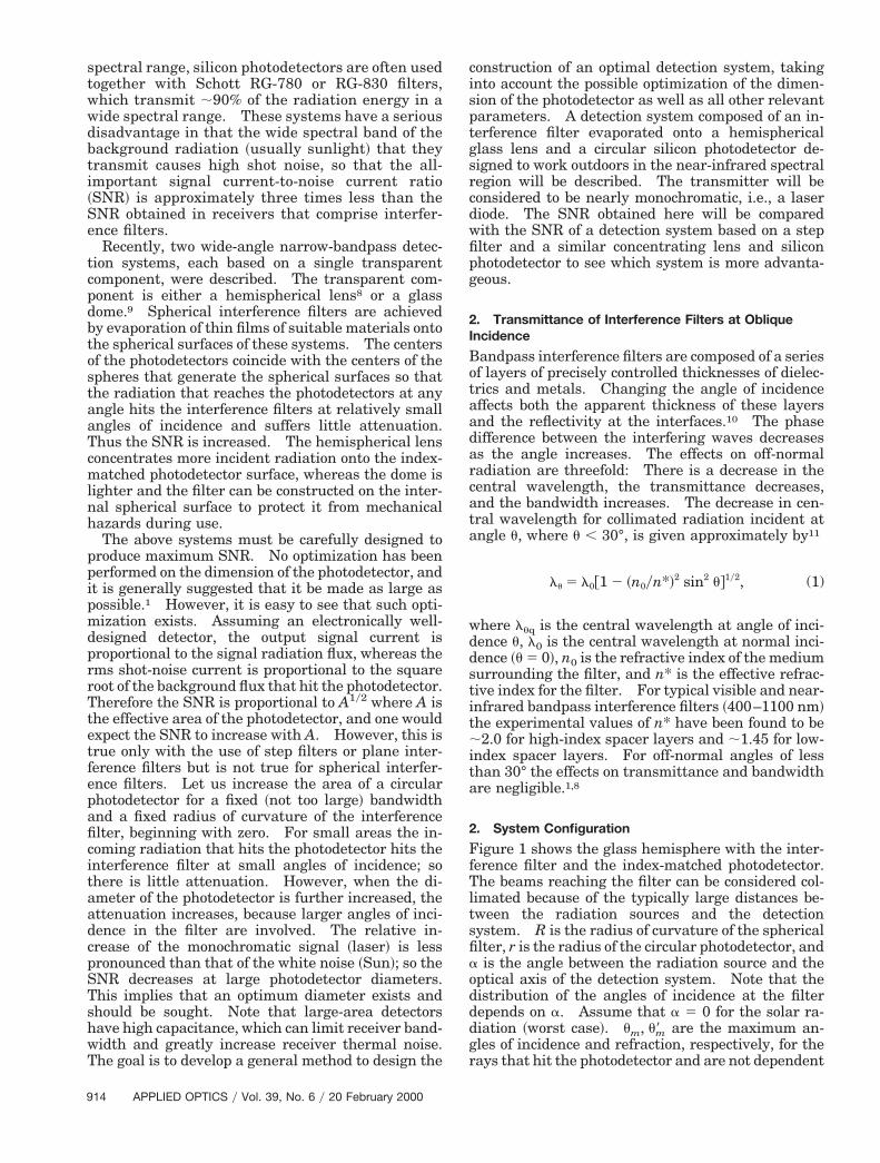
Increasing both the photodetector radius r and thepherical interference-filter radius R by the same fac-or, while keeping the other parameters fixed, doesot change the distribution of the angles of incidencet the filter while the effective areas “seen” by theignal and by the noise radiation increase byhe same factor. Since the signal is proportional tohe effective area and the noise is proportional to itsquare root, the SNR increases. Generally the valuef R does not exceed several centimeters. It wasound that for a specific value of R there is an optimalalue of r that maximizes the SNR of the system ~seeig. 2, solid curves!. For larger filter bandwidthshe optimal r is larger ~Fig. 2, dashed curve!. Asxplained in Section 1, the reason for the existence of
20 February 2000 y Vol. 39, No. 6 y APPLIED OPTICS 915
1
sra
9
an optimal r value is that for small photodetectordimensions the SNR function increases linearly as afunction of r; but after reaching the maximum theSNR decreases as 1yr for large r values, because onlythe white background radiation continues to betransmitted. For a fixed R, r is larger for largerfilter bandwidths, because rays that hit the filter atlarger angles of incidence are transmitted. Thus, inaddition to their high capacitance, large photodetec-tors may decrease the optical SNR.
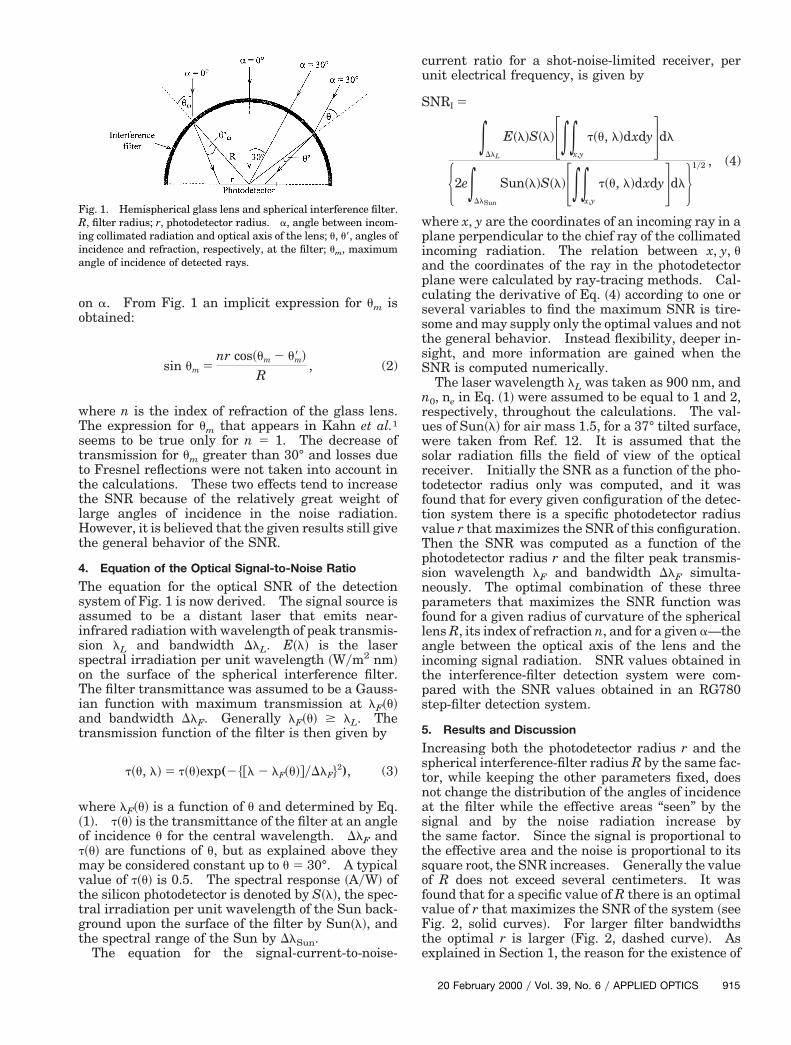
Figure 3 shows the ratio of the SNR of ~nonoptimal!spherical interference-filter devices to the SNR ofstep-filter devices, as a function of the photodetectorradius with other parameters fixed. For small pho-todetectors the spherical interference filter is prefer-able. However, for large photodetector radii thecurve reaches a maximum for the optimal photode-tector radius and then decreases as 1yr for large pho-todetector radii because the SNR of a step-filtersystem is linear in r while the SNR of a sphericalfilter system remains constant for large photodetec-tors.
It is expected8 that the maximum values of theSNR in the spherical interference-filter system in-crease with increasing radius of curvature of the filterR for a fixed r value. However, it was found that thiseffect becomes smaller for large R values and thatincreasing R beyond ten times r has a negligible effecton the SNR. Thus one gains nothing by increasingR beyond that. Comparatively, increasing the ra-dius of the hemispherical lens in the step-filter detec-tion system beyond twice the value of the
Fig. 2. Normalized SNR of spherical interference-filter detectionsystems as a function of photodetector radius r. R, radius ofcurvature of the filter; DlF, filter bandwidth. Peak wavelength oflaser radiation and filter transmission l 5 900 nm. Index ofrefraction of hemispherical lens n 5 1.5. Angle between trans-mitter and optical axis of the lens a 5 30°.
Fig. 3. Ratio of SNR values of a spherical interference-filter de-tection system to SNR values of a step-filter detection system, as afunction of photodetector radius. R 5 2 cm, n 5 1.5, lF 5 900 nm,DlF 5 5 nm.
16 APPLIED OPTICS y Vol. 39, No. 6 y 20 February 2000
photodetector radius does not increase the SNR.For R .. r the detected rays hit the filter at nearlyzero angles of incidence. The signal and the noiseseparately approach a limit, because the effective ar-eas of the spherical surface that participate in thetransmittance of the rays that hit the photodetectorcease to be dependent on R and separately reach alimit.
The above SNR values were obtained for optimal rvalues but without simultaneous optimization of theother parameters. For example, the peak transmis-sion wavelength of the interference filter lF has beentaken as fixed and equal to the laser wavelength lLthroughout the calculations. The fully optimizedspherical-interference-filter detection systems wherethe optimal lF and DlF were calculated for severalvalues of a, R, and n as a function of r, are nowdiscussed.
For a given spherical lens and photodetector radiusthe optimal interference-filter bandwidth DlF de-pends on the maximum angle of incidence um
1 for agiven a. For small photodetectors relatively smallangles of incidence u are involved, and the optimalfilter bandwidth is smaller than or equal to the laserbandwidth, whereas for large photodetectors the fol-lowing approximate relation was found for optimiza-tion:
DlF < lF 2 lL. (5)
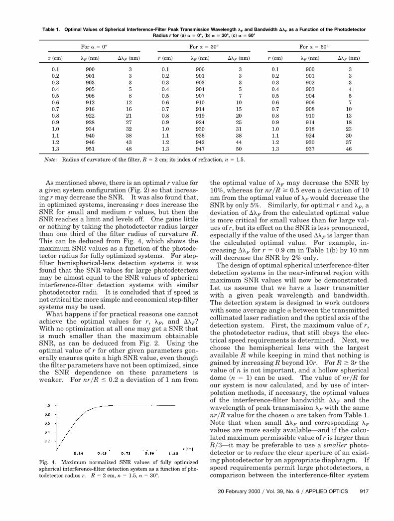
Therefore lF also depends on um. From Eq. ~2! wesee that this implies that the optimal interference-filter bandwidth and peak wavelength depend mainlyon nryR for a given transmitter wavelength andbandwidth. The optimal filter parameters willchange, however, with a, because the distribution ofthe angles of incidence of the signal depends on a. Itcan be concluded that, once the optimal values of lFand DlF are known as a function of nryR for some a,these values can be determined for any combinationof n, R, and r for the same a. This has been verified inmany computer simulations and may be useful in thedesignation of optimal spherical interference-filterdetection systems working at the same wavelengthregion. Table 1 gives the optimal values of the filterfor several values of a. For convenience the optimalvalues are given as a function of r and not as a func-tion of nryR, for R 5 2 cm and n 5 1.5.
For a fixed R value the maximum SNR values ~i.e.,for optimal values of r, lF, and DlF! increase withincreasing n for small photodetector radius—approximately one tenth of the hemispherical lensradius, ryR ; 1y10, because of the increase of theeffective transmitting areas of the lens. For ryR $
y3 the maximum SNR is independent of n. Thismeans that for medium-size photodetectors equalSNR values can be achieved in optimized hemispher-ical dome systems9 ~n 5 1! and hemispherical lenssystems8 ~n . 1!. Comparatively, the SNR of thetep-filter system is proportional to n, the index ofefraction of the hemispherical lens, for small as wells for large photodetector dimensions.
SotTmtfifmipns
a
n
d
etcw
dmLwTwcdttcagvdopo
N
Table 1. Optimal Values of Spherical Interference-Filter Peak Transmission Wavelength l and Bandwidth Dl as a Function of the Photodetector
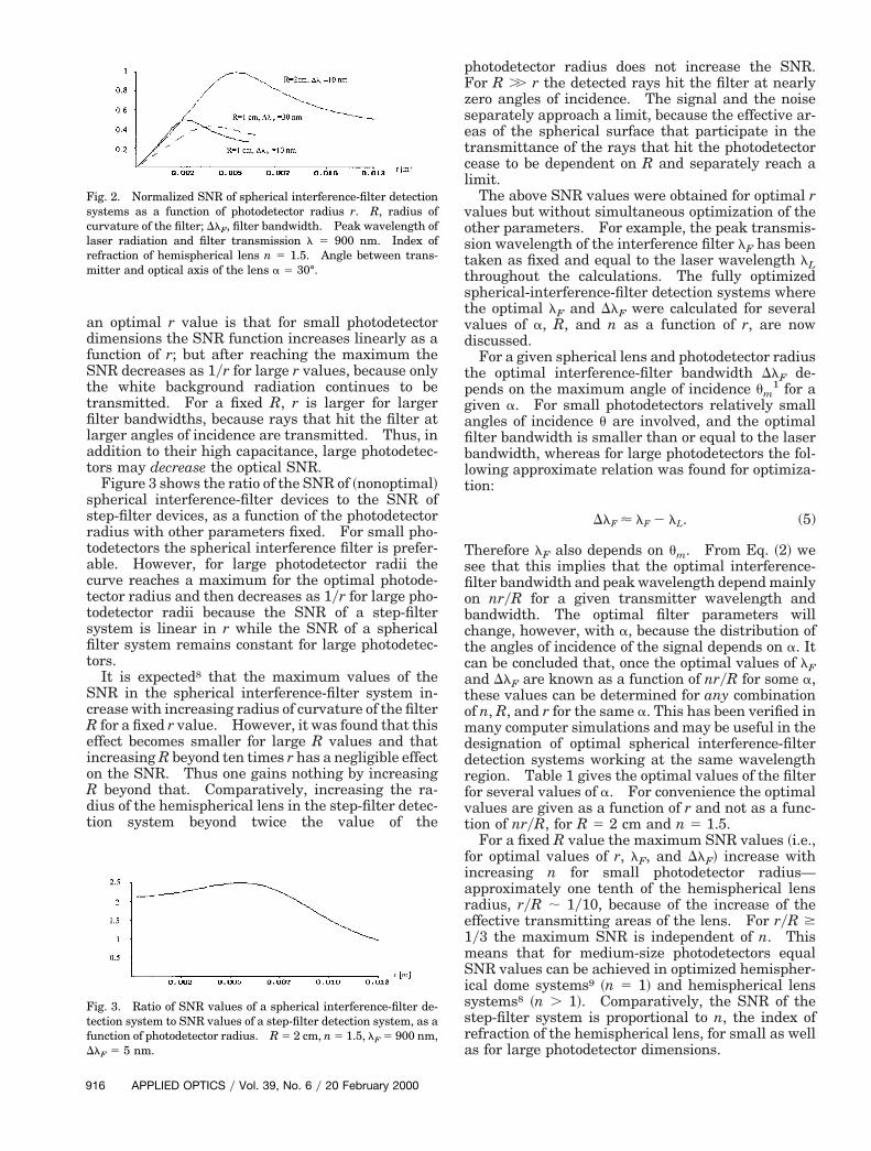
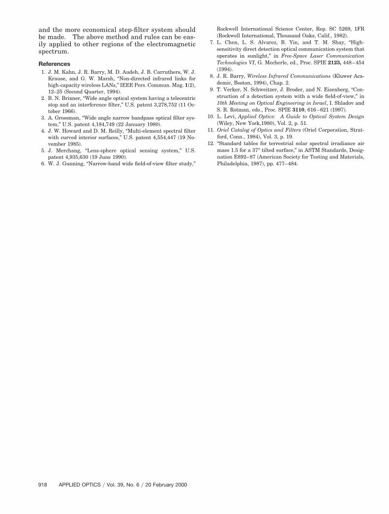
As mentioned above, there is an optimal r value fora given system configuration ~Fig. 2! so that increas-ing r may decrease the SNR. It was also found that,in optimized systems, increasing r does increase theSNR for small and medium r values, but then the
NR reaches a limit and levels off. One gains littler nothing by taking the photodetector radius largerhan one third of the filter radius of curvature R.his can be deduced from Fig. 4, which shows theaximum SNR values as a function of the photode-
ector radius for fully optimized systems. For step-lter hemispherical-lens detection systems it wasound that the SNR values for large photodetectors
ay be almost equal to the SNR values of sphericalnterference-filter detection systems with similarhotodetector radii. It is concluded that if speed isot critical the more simple and economical step-filterystems may be used.What happens if for practical reasons one cannot
chieve the optimal values for r, lF, and DlF?With no optimization at all one may get a SNR thatis much smaller than the maximum obtainableSNR, as can be deduced from Fig. 2. Using theoptimal value of r for other given parameters gen-erally ensures quite a high SNR value, even thoughthe filter parameters have not been optimized, sincethe SNR dependence on these parameters isweaker. For nryR # 0.2 a deviation of 1 nm from
Fig. 4. Maximum normalized SNR values of fully optimizedspherical interference-filter detection system as a function of pho-todetector radius r. R 5 2 cm, n 5 1.5, a 5 30°.
Radius r for ~a! a 5 0
For a 5 0° For
r ~cm! lF ~nm! DlF ~nm! r ~cm! lF
0.1 900 3 0.1 90.2 901 3 0.2 90.3 903 3 0.3 90.4 905 5 0.4 90.5 908 8 0.5 90.6 912 12 0.6 90.7 916 16 0.7 90.8 922 21 0.8 90.9 928 27 0.9 91.0 934 32 1.0 91.1 940 38 1.1 91.2 946 43 1.2 91.3 951 48 1.3 9
Note: Radius of curvature of the filter, R 5 2 cm; its index of
the optimal value of lF may decrease the SNR by10%, whereas for nryR $ 0.5 even a deviation of 10
m from the optimal value of lF would decrease theSNR by only 5%. Similarly, for optimal r and lF, a
eviation of DlF from the calculated optimal valueis more critical for small values than for large val-ues of r, but its effect on the SNR is less pronounced,specially if the value of the used DlF is larger thanhe calculated optimal value. For example, in-reasing DlF for r 5 0.9 cm in Table 1~b! by 10 nmill decrease the SNR by 2% only.The design of optimal spherical interference-filter
etection systems in the near-infrared region withaximum SNR values will now be demonstrated.et us assume that we have a laser transmitterith a given peak wavelength and bandwidth.he detection system is designed to work outdoorsith some average angle a between the transmitted
ollimated laser radiation and the optical axis of theetection system. First, the maximum value of r,he photodetector radius, that still obeys the elec-rical speed requirements is determined. Next, wehoose the hemispherical lens with the largestvailable R while keeping in mind that nothing isained by increasing R beyond 10r. For R $ 3r thealue of n is not important, and a hollow sphericalome ~n 5 1! can be used. The value of nryR forur system is now calculated, and by use of inter-olation methods, if necessary, the optimal valuesf the interference-filter bandwidth DlF and the
wavelength of peak transmission lF with the samenryR value for the chosen a are taken from Table 1.
ote that when small DlF and corresponding lFvalues are more easily available—and if the calcu-lated maximum permissible value of r is larger thanRy3—it may be preferable to use a smaller photo-detector or to reduce the clear aperture of an exist-ing photodetector by an appropriate diaphragm. Ifspeed requirements permit large photodetectors, acomparison between the interference-filter system
F F
a 5 30°, ~c! a 5 60°
30° For a 5 60°
DlF ~nm! r ~cm! lF ~nm! DlF ~nm!
3 0.1 900 33 0.2 901 33 0.3 902 35 0.4 903 47 0.5 904 5
10 0.6 906 715 0.7 908 1020 0.8 910 1325 0.9 914 1831 1.0 918 2338 1.1 924 3044 1.2 930 3750 1.3 937 46
ction, n 5 1.5.
°, ~b!
a 5
~nm!
00010304071014192430364247
refra
20 February 2000 y Vol. 39, No. 6 y APPLIED OPTICS 917
Rockwell International Science Center, Rep. SC 5269, 1FR
9
and the more economical step-filter system shouldbe made. The above method and rules can be eas-ily applied to other regions of the electromagneticspectrum.
References1. J. M. Kahn, J. R. Barry, M. D. Audeh, J. B. Carruthers, W. J.
Krause, and G. W. Marsh, “Non-directed infrared links forhigh-capacity wireless LANs,” IEEE Pers. Commun. Mag. 1~2!,12–25 ~Second Quarter, 1994!.
2. B. N. Brixner, “Wide angle optical system having a telecentricstop and an interference filter,” U.S. patent 3,278,752 ~11 Oc-tober 1966!.
3. A. Grossman, “Wide angle narrow bandpass optical filter sys-tem,” U.S. patent 4,184,749 ~22 January 1980!.
4. J. W. Howard and D. M. Reilly, “Multi-element spectral filterwith curved interior surfaces,” U.S. patent 4,554,447 ~19 No-vember 1985!.
5. J. Merchang, “Lens-sphere optical sensing system,” U.S.patent 4,935,630 ~19 June 1990!.
6. W. J. Gunning, “Narrow-band wide field-of-view filter study,”
18 APPLIED OPTICS y Vol. 39, No. 6 y 20 February 2000
~Rockwell International, Thousand Oaks, Calif., 1982!.7. L. Chen, L. S. Alvarez, B. Yin, and T. M. Shay, “High-
sensitivity direct detection optical communication system thatoperates in sunlight,” in Free-Space Laser CommunicationTechnologies VI, G. Mecherle, ed., Proc. SPIE 2123, 448–454~1994!.
8. J. R. Barry, Wireless Infrared Communications ~Kluwer Aca-demic, Boston, 1994!, Chap. 2.
9. T. Verker, N. Schweitzer, J. Broder, and N. Eisenberg, “Con-struction of a detection system with a wide field-of-view,” in10th Meeting on Optical Engineering in Israel, I. Shladov andS. R. Rotman, eds., Proc. SPIE 3110, 616–621 ~1997!.
10. L. Levi, Applied Optics: A Guide to Optical System Design~Wiley, New York,1980!, Vol. 2, p. 51.
11. Oriel Catalog of Optics and Filters ~Oriel Corporation, Strat-ford, Conn., 1984!, Vol. 3, p. 19.
12. “Standard tables for terrestrial solar spectral irradiance airmass 1.5 for a 37° tilted surface,” in ASTM Standards, Desig-nation E892–87 ~American Society for Testing and Materials,Philadelphia, 1987!, pp. 477–484.