Embed Size (px)
Citation preview
Wide-angle Micro Sensors for Vision on a Tight Budget
Sanjeev J. Koppal∗
Harvard UniversityIoannis Gkioulekas∗
Harvard UniversityTodd Zickler∗
Harvard UniversityGeoffrey L. Barrows†
Centeye, Inc.
Abstract
Achieving computer vision on micro-scale devices is achallenge. On these platforms, the power and mass con-straints are severe enough for even the most common com-putations (matrix manipulations, convolution, etc.) to bedifficult. This paper proposes and analyzes a class ofminiature vision sensors that can help overcome these con-straints. These sensors reduce power requirements throughtemplate-based optical convolution, and they enable a widefield-of-view within a small form through a novel opticaldesign. We describe the trade-offs between the field of view,volume, and mass of these sensors and we provide analytictools to navigate the design space. We also demonstratemilli-scale prototypes for computer vision tasks such as lo-cating edges, tracking targets, and detecting faces.
1. IntroductionThe recent availability of portable camera-equipped
computers, such as smart-phones, has created a surge of in-terest in computer vision tools that can run within limitedpower and mass budgets. For these platforms, the focushas been to create optimized hardware and software to ana-lyze conventional images in a highly efficient manner. Yet,there is a class of platforms that are still smaller. Theseare micro-platforms (characteristic size <1mm) that havepower and mass constraints severe enough for large-scalematrix manipulations, convolution, and other core compu-tations to be impossible. These platforms appear in manydomains, including micro-robots and other small machines[8], and nodes of far-flung sensor networks [32].
Power is the critical issue when shrinking a vision sys-tem to the micro scale, with many platforms having averagepower budgets on the order of milli-Watts. In this paper,we present and analyze a class of micro vision sensors thatcan help overcome the constraints of low power. Arrays ofthese sensors could handle a specific vision task, like facedetection, as depicted in Fig. 1.
A wide field-of-view (FOV) is important for savingpower, since low-FOV devices must either pan a single sen-sor or carry multiple sensors with different viewpoints. Ourdesigns obtain a large FOV within a small form by exploit-
∗(sjkoppal,igkiou,zickler)@seas.harvard.edu†[email protected]
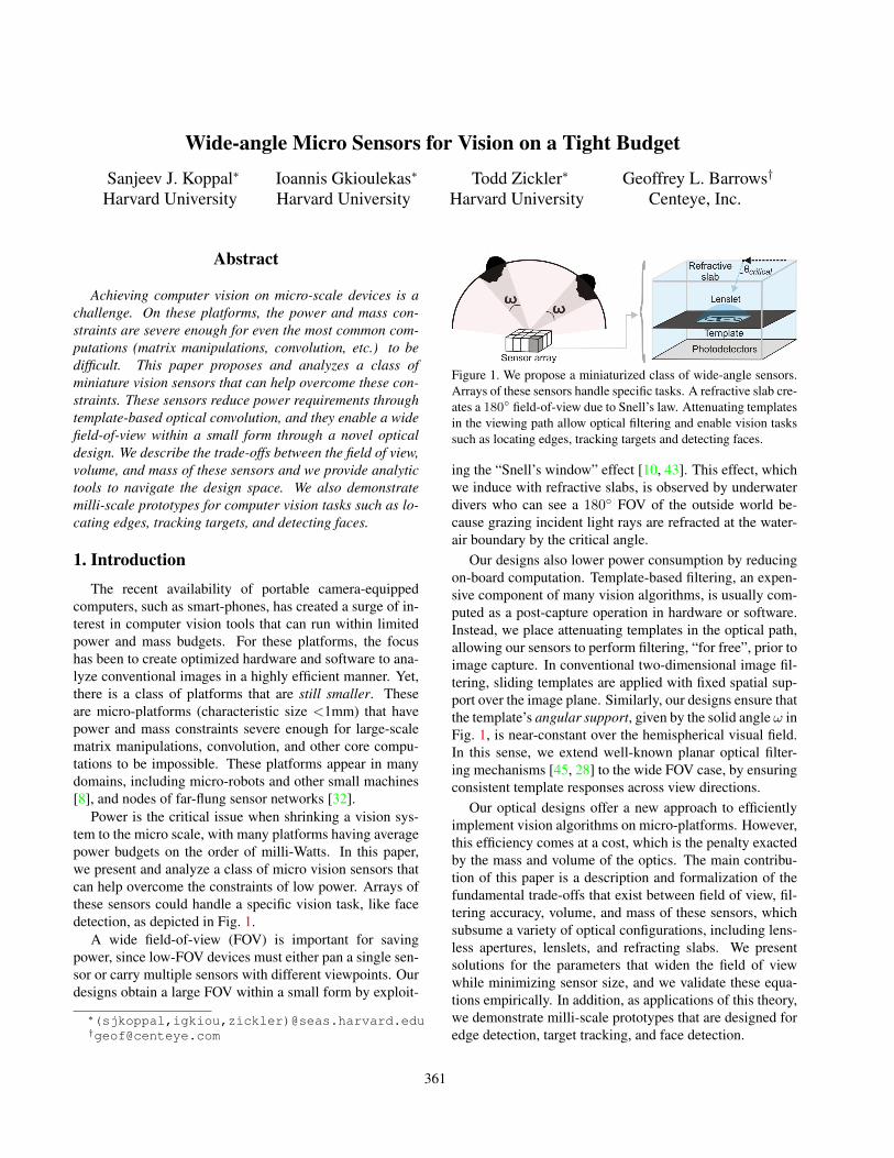
Figure 1. We propose a miniaturized class of wide-angle sensors.Arrays of these sensors handle specific tasks. A refractive slab cre-ates a 180◦ field-of-view due to Snell’s law. Attenuating templatesin the viewing path allow optical filtering and enable vision taskssuch as locating edges, tracking targets and detecting faces.
ing the “Snell’s window” effect [10, 43]. This effect, whichwe induce with refractive slabs, is observed by underwaterdivers who can see a 180◦ FOV of the outside world be-cause grazing incident light rays are refracted at the water-air boundary by the critical angle.
Our designs also lower power consumption by reducingon-board computation. Template-based filtering, an expen-sive component of many vision algorithms, is usually com-puted as a post-capture operation in hardware or software.Instead, we place attenuating templates in the optical path,allowing our sensors to perform filtering, “for free”, prior toimage capture. In conventional two-dimensional image fil-tering, sliding templates are applied with fixed spatial sup-port over the image plane. Similarly, our designs ensure thatthe template’s angular support, given by the solid angle ω inFig. 1, is near-constant over the hemispherical visual field.In this sense, we extend well-known planar optical filter-ing mechanisms [45, 28] to the wide FOV case, by ensuringconsistent template responses across view directions.
Our optical designs offer a new approach to efficientlyimplement vision algorithms on micro-platforms. However,this efficiency comes at a cost, which is the penalty exactedby the mass and volume of the optics. The main contribu-tion of this paper is a description and formalization of thefundamental trade-offs that exist between field of view, fil-tering accuracy, volume, and mass of these sensors, whichsubsume a variety of optical configurations, including lens-less apertures, lenslets, and refracting slabs. We presentsolutions for the parameters that widen the field of viewwhile minimizing sensor size, and we validate these equa-tions empirically. In addition, as applications of this theory,we demonstrate milli-scale prototypes that are designed foredge detection, target tracking, and face detection.
361

2. Related workEfficient hardware for micro computer vision. Our re-search complements work done in the embedded systemscommunity [42, 5], since their hardware and software canbe coupled with our optimized optics for even greater ef-ficiency. In fact, all sources of efficiency should be con-sidered, given the power budgets available for micro plat-forms. For example, the successful convolution networksframework [23] was recently implemented on FPGA hard-ware with a peak power consumption of only 15W [12],but this is many orders of magnitude larger than what mi-cro platforms are likely to support. Indeed, micro-scalenetwork nodes may require an average power consumptionof around 140µW [15, 6]. Furthermore, micro-robot peakpower consumption is around 100mW [19], with averagepower consumption around 5-10mW [33, 41], with almostall of it dedicated to motion.Applied optics and computational photography. Fourieroptics [14, 44] involves designing point spread functions(PSFs) of coherent-light systems to implement computa-tions like Fourier transforms. This has limited impactfor real-world vision systems that must process incoher-ent scene radiance. That said, controllable PSFs arewidely used in computer vision, where attenuating tem-plates are placed in the optical path, for deblurring [38],refocussing [29], active light-transport capture [30], depthsensing [24] and compressive imaging [9]. In all of thesecases, the optical encoding increases the information cap-tured and allows post-capture decoding of the measure-ments for full-resolution imaging or light-field reconstruc-tion. In contrast to this encode-decode imaging pipeline,we seek optics that distill the incoming light to reduce post-capture processing. In this sense, our approach is closer totechniques that filter optically with liquid crystal displays(LCDs) [45] or digital micro-mirror devices (DMDs) [28].However, unlike these active, full-size systems, we seekpassive optical filtering on micro-platforms, and this re-quires a new class of wide-field optics. (Geometric relationsbetween our work and [45] are given in the Appendix.)Wide-field imaging in vision and optics. The Snell’s win-dow effect has been exploited in a classical “water camera”[43], and the projective geometry of this pinhole camerahas been recently described [7]. The inverse critical-angleeffect has been used to model air-encased cameras underwa-ter [36]. In addition to these flat refractive optical designs,a variety of wide FOV imaging systems exist in vision andoptics [34, 27]; and micro-optics for imaging is an activefield [16, 40, 35]. While we draw on ideas from these pre-vious efforts, our goal is quite different because we seekimage analysis instead of image capture. This leads to verydifferent designs. Our optics cannot be designed by com-mercial ray-tracing tools [1], for example, because these arecreated for imaging and not optical filtering.
Figure 2. Ray diagram of our design: By embedding a lens ina medium, we can maintain a near-constant angular support overa larger range of angles and increase the effective field of view toencompass most of the hemisphere of directions.
3. Design overviewA ray diagram of our design, shown Fig. 2, depicts a
lenslet embedded in a refractive slab and placed over an at-tenuating template. For clarity we present a 2D figure, butsince the optics are radially symmetric our arguments holdin three dimensions. Each location on the photodetector ar-ray x defines a single viewing direction θ and collects lightfrom the scene over the angular support ω. Note that eachviewing direction, θ, is contained in (0, π). In our analysiswe are particularly interested in the sensor’s effective field-of-view (eFOV), which is the range of viewing directionsover which the variation in the template’s angular support ωis lower than a user-defined error threshold.
We depict a single sensing element above, with the un-derstanding that for any practical application (see examplesin Fig. 7) a functioning sensor will be assembled by tilingmany of these elements, as in Fig. 1. We will also assumethe templates are monochromatic, but we point out that, un-like conventional post-capture image filtering, optical tem-plates can be easily designed with a specified spectral sen-sitivity. Therefore “multi-spectral” templates can be manu-factured and each template’s transmissivity can be selectedto maximize performance in certain vision tasks. This is animportant advantage of our sensor design over conventionalvision systems, which we discuss further in Section 6.
The refractive indices of the medium (n1) and the lens(n2) allow for a variety of optical configurations, includinga lensless template (n1 = n2 = 1), a template embedded ina refractive slab (n1 = n2 > 1), a template with a micro-lens (n1 = 1, n2 > n1), and a template with a lens and em-bedding slab (n2 > n1 > 1). We restrict ourselves to thesesetups since they can be readily microfabricated [4]. Alter-natives are discussed in Section 6. Note that we set the em-bedding medium’s height to exactly v, which is the lenslet’splane of focus. This is possible without any loss of general-ity, since the scene is distant.
362

4. AnalysisOur goal is to analyze the class of sensing elements
shown in Fig. 2, formalizing the tradeoffs between the ef-fective field of view and the element’s volume and mass.A single sensor’s design parameters form a five dimen-sional vector Π = {u, d, n1, n2, R}, where u is the templateheight, d is the template width, n1 is the medium’s refrac-tive index, n2 is the lenslet’s refractive index, and R is itsradius of curvature. Choosing a set of design parameters Πdetermines the angular support measured in each view di-rection θ, and we represent this as a scalar angular supportfunction, ω(θ; Π). For convenience, we shorten this func-tion to ω(θ), or ω(x), since there is a one-to-one mappingbetween viewing angle θ and photodetector coordinate x.
We define the effective field of view (eFOV) to be theset of view directions for which the angular support issufficiently close to a constant, desired angular supportωo. Formally, we write this as |Θ| with Θ = {θ :F (ω(θ; Π), ωo) ≤ ∆}, where ∆ is a user-defined thresh-old, and F (ω(θ; Π), ωo) is some distance metric. We willassume Θ includes the optical axis (θ = π
2 ), and we use theL2 distance metric, so that F (ω, ωo) = ||ω − ωo||2.
While templates can be fabricated by a variety of pro-cesses, there will be limits to the achievable spatial res-olution and, equivalently, the minimum “dot pitch”. Thisgets translated, through our optics, into an angular resolu-tion over the support ω. For a particular setup, there will bea minimum angular resolution that can be tolerated and werepresent this as the corresponding angular dot pitch dω.
Suppose we wish to implement a particular filtering op-erator, which is optically defined by the design specifica-tions Ξ = {ωo, ∆, dω, F}. Let the first element of Ξ be 10◦;this means that our design should have a near-constant an-gular support of ω ≈ 10◦ over a wide field of view. If thereexists a family of design parameters Π that can achieve thisgoal, how do we find “good” members of this family? Ofcourse, depending on the application and the platform, the“best” design could be one with minimum volume or mass(or both), or one that provides the maximum possible eFOVor perhaps the maximum eFOV under some size constraints.
The main contribution of this section is to derive equa-tions and present empirical analysis, in the form of a look-up table, to answer all these types of questions, and allowdesigning a custom sensor. For all cases, we show experi-mental validation, summarized in Fig. 5.
Note that the design parameters Π are limited by a num-ber of constraints Ψ, of which there are two classes:
• The design parameters Π must be physically plausible,with u, d,R ≥ 0, n1, n2 ≥ 1, d ≤ 2R (from the lensequation) and n2 ≥ n1 (to create a convex lens).• The design parameters Π must allow easy micro-
fabrication. Diffraction effects [26] place a strict lower
Figure 3. Optimal lensless parameters: I shows measured andsimulated solid angles for three template heights u for a d =0.1mm pinhole. The measured angles compare well to simula-tions. The maximum eFOV occurs at an optimal u peak in II.
bound on our ability to shrink the designs, but in prac-tice, three issues emerge earlier: the minimum tem-plate width dmin for which the template printing pro-cess can still achieve the desired angular dot pitch dω;the maximum photodetector array lengthEmax, whichmay be fixed or custom built; and t, the aperture thick-ness, shown in Fig. 2, whose vignetting effect on an-gular support is explained in the Appendix.
4.1. Designs without Snell’s window
Consider a lensless version of Fig. 2 where the refrac-tive indices n1 = n2 = 1 imply that both the internal an-gular supports, ω
′and ω
′′, are equal to the external angular
support ω. Therefore the design parameter space is two-dimensional, Π = {u, d}. Fig. 3(I) shows angular supportcurves ω(θ) for a fixed template width d = 0.1mm and threedifferent template heights u = {4, 6.5, 10.5}. These curveswere measured using our prototype, shown in Fig. 7 (I).
This figure shows how the angular support function un-dergoes approximate vertical shifts as the template height uvaries. The central curve, which is tangential to the upperbound ωo + ∆
2 , is most desirable because it provides thelargest eFOV. Since mass is negligible for this design, wecan define an “optimal design Π∗” as the one that achievesthis largest possible eFOV while fitting within the smallestpossible volume, given the constraints Ψ.
We will find this optimal design in three steps: (1) ran-domly select a large value for template width d; (2) finda template height u such that the (u, d) pair has maximaleFOV; and (3) globally scale down the design till we reach aconstraint in Ψ. In our discussion, we will consider only theconstraint of minimum template width dmin, but the same
363
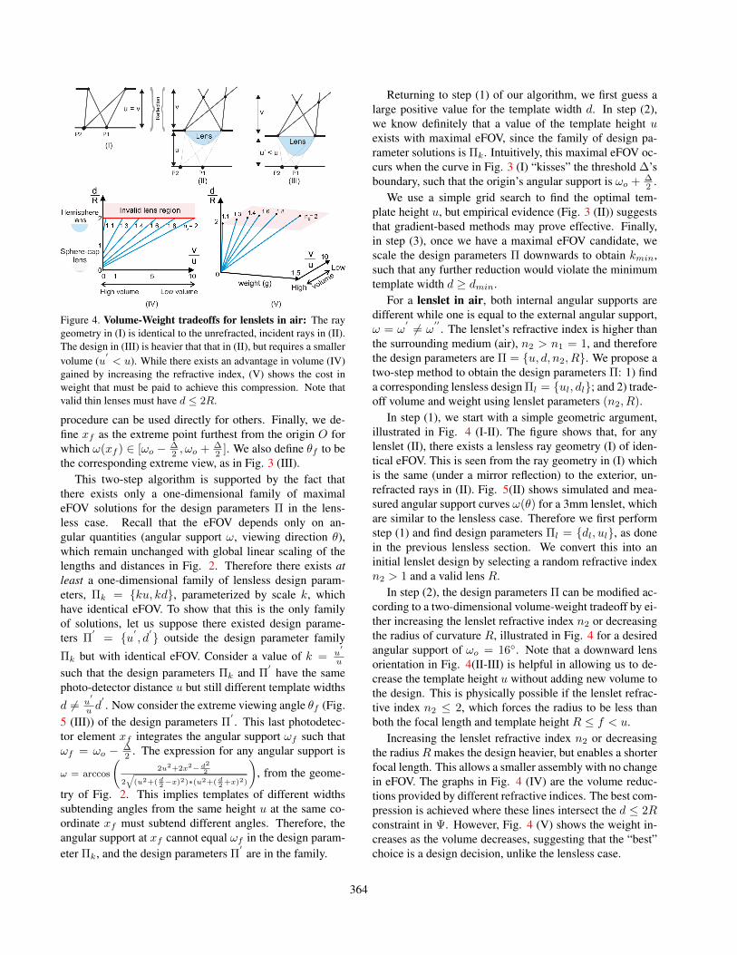
Figure 4. Volume-Weight tradeoffs for lenslets in air: The raygeometry in (I) is identical to the unrefracted, incident rays in (II).The design in (III) is heavier that that in (II), but requires a smallervolume (u
′< u). While there exists an advantage in volume (IV)
gained by increasing the refractive index, (V) shows the cost inweight that must be paid to achieve this compression. Note thatvalid thin lenses must have d ≤ 2R.
procedure can be used directly for others. Finally, we de-fine xf as the extreme point furthest from the origin O forwhich ω(xf ) ∈ [ωo − ∆
2 , ωo + ∆2 ]. We also define θf to be
the corresponding extreme view, as in Fig. 3 (III).This two-step algorithm is supported by the fact that
there exists only a one-dimensional family of maximaleFOV solutions for the design parameters Π in the lens-less case. Recall that the eFOV depends only on an-gular quantities (angular support ω, viewing direction θ),which remain unchanged with global linear scaling of thelengths and distances in Fig. 2. Therefore there exists atleast a one-dimensional family of lensless design param-eters, Πk = {ku, kd}, parameterized by scale k, whichhave identical eFOV. To show that this is the only familyof solutions, let us suppose there existed design parame-ters Π
′= {u′
, d′} outside the design parameter family
Πk but with identical eFOV. Consider a value of k = u′
u
such that the design parameters Πk and Π′
have the samephoto-detector distance u but still different template widthsd 6= u
′
u d′. Now consider the extreme viewing angle θf (Fig.
5 (III)) of the design parameters Π′. This last photodetec-
tor element xf integrates the angular support ωf such thatωf = ωo − ∆
2 . The expression for any angular support is
ω = arccos
(2u2+2x2− d2
2
2√
(u2+( d2−x)2)∗(u2+( d
2+x)2)
), from the geome-
try of Fig. 2. This implies templates of different widthssubtending angles from the same height u at the same co-ordinate xf must subtend different angles. Therefore, theangular support at xf cannot equal ωf in the design param-eter Πk, and the design parameters Π
′are in the family.
Returning to step (1) of our algorithm, we first guess alarge positive value for the template width d. In step (2),we know definitely that a value of the template height uexists with maximal eFOV, since the family of design pa-rameter solutions is Πk. Intuitively, this maximal eFOV oc-curs when the curve in Fig. 3 (I) “kisses” the threshold ∆’sboundary, such that the origin’s angular support is ωo + ∆
2 .We use a simple grid search to find the optimal tem-
plate height u, but empirical evidence (Fig. 3 (II)) suggeststhat gradient-based methods may prove effective. Finally,in step (3), once we have a maximal eFOV candidate, wescale the design parameters Π downwards to obtain kmin,such that any further reduction would violate the minimumtemplate width d ≥ dmin.
For a lenslet in air, both internal angular supports aredifferent while one is equal to the external angular support,ω = ω
′ 6= ω′′
. The lenslet’s refractive index is higher thanthe surrounding medium (air), n2 > n1 = 1, and thereforethe design parameters are Π = {u, d, n2, R}. We propose atwo-step method to obtain the design parameters Π: 1) finda corresponding lensless design Πl = {ul, dl}; and 2) trade-off volume and weight using lenslet parameters (n2, R).
In step (1), we start with a simple geometric argument,illustrated in Fig. 4 (I-II). The figure shows that, for anylenslet (II), there exists a lensless ray geometry (I) of iden-tical eFOV. This is seen from the ray geometry in (I) whichis the same (under a mirror reflection) to the exterior, un-refracted rays in (II). Fig. 5(II) shows simulated and mea-sured angular support curves ω(θ) for a 3mm lenslet, whichare similar to the lensless case. Therefore we first performstep (1) and find design parameters Πl = {dl, ul}, as donein the previous lensless section. We convert this into aninitial lenslet design by selecting a random refractive indexn2 > 1 and a valid lens R.
In step (2), the design parameters Π can be modified ac-cording to a two-dimensional volume-weight tradeoff by ei-ther increasing the lenslet refractive index n2 or decreasingthe radius of curvature R, illustrated in Fig. 4 for a desiredangular support of ωo = 16◦. Note that a downward lensorientation in Fig. 4(II-III) is helpful in allowing us to de-crease the template height u without adding new volume tothe design. This is physically possible if the lenslet refrac-tive index n2 ≤ 2, which forces the radius to be less thanboth the focal length and template height R ≤ f < u.
Increasing the lenslet refractive index n2 or decreasingthe radius R makes the design heavier, but enables a shorterfocal length. This allows a smaller assembly with no changein eFOV. The graphs in Fig. 4 (IV) are the volume reduc-tions provided by different refractive indices. The best com-pression is achieved where these lines intersect the d ≤ 2Rconstraint in Ψ. However, Fig. 4 (V) shows the weight in-creases as the volume decreases, suggesting that the “best”choice is a design decision, unlike the lensless case.
364
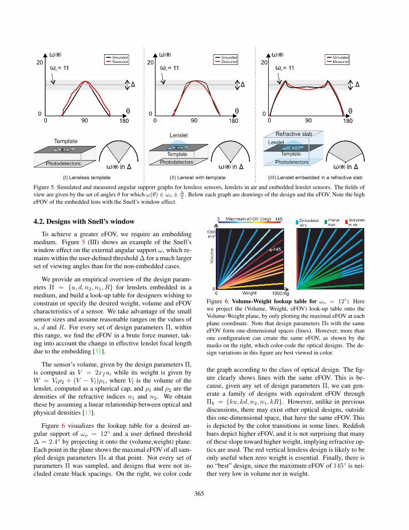
Figure 5. Simulated and measured angular support graphs for lensless sensors, lenslets in air and embedded lenslet sensors. The fields ofview are given by the set of angles θ for which ω(θ) ∈ ωo± ∆
2. Below each graph are drawings of the design and the eFOV. Note the high
eFOV of the embedded lens with the Snell’s window effect.
4.2. Designs with Snell’s window
To achieve a greater eFOV, we require an embeddingmedium. Figure 5 (III) shows an example of the Snell’swindow effect on the external angular support ω, which re-mains within the user-defined threshold ∆ for a much largerset of viewing angles than for the non-embedded cases.
We provide an empirical overview of the design param-eters Π = {u, d, n2, n1, R} for lenslets embedded in amedium, and build a look-up table for designers wishing toconstrain or specify the desired weight, volume and eFOVcharacteristics of a sensor. We take advantage of the smallsensor sizes and assume reasonable ranges on the values ofu, d and R. For every set of design parameters Π, withinthis range, we find the eFOV in a brute force manner, tak-ing into account the change in effective lenslet focal lengthdue to the embedding [31].
The sensor’s volume, given by the design parameters Π,is computed as V = 2xfu, while its weight is given byW = Vlρ2 + (V − Vl)ρ1, where Vl is the volume of thelenslet, computed as a spherical cap, and ρ1 and ρ2 are thedensities of the refractive indices n1 and n2. We obtainthese by assuming a linear relationship between optical andphysical densities [13].
Figure 6 visualizes the lookup table for a desired an-gular support of ωo = 12◦ and a user defined threshold∆ = 2.4◦ by projecting it onto the (volume,weight) plane.Each point in the plane shows the maximal eFOV of all sam-pled design parameters Πs at that point. Not every set ofparameters Π was sampled, and designs that were not in-cluded create black spacings. On the right, we color code
Figure 6. Volume-Weight lookup table for ωo = 12◦: Herewe project the (Volume, Weight, eFOV) look-up table onto theVolume-Weight plane, by only plotting the maximal eFOV at eachplane coordinate. Note that design parameters Πs with the sameeFOV form one-dimensional spaces (lines). However, more thanone configuration can create the same eFOV, as shown by themasks on the right, which color-code the optical designs. The de-sign variations in this figure are best viewed in color.
the graph according to the class of optical design. The fig-ure clearly shows lines with the same eFOV. This is be-cause, given any set of design parameters Π, we can gen-erate a family of designs with equivalent eFOV throughΠk = {ku, kd, n2, n1, kR}. However, unlike in previousdiscussions, there may exist other optical designs, outsidethis one-dimensional space, that have the same eFOV. Thisis depicted by the color transitions in some lines. Reddishhues depict higher eFOV, and it is not surprising that manyof these slope toward higher weight, implying refractive op-tics are used. The red vertical lensless design is likely to beonly useful when zero weight is essential. Finally, there isno “best” design, since the maximum eFOV of 145◦ is nei-ther very low in volume nor in weight.
365
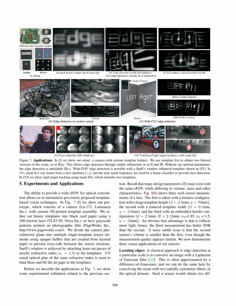
Figure 7. Applications: In (I) we show our setup: a camera with custom template holders. We use template I(a) to obtain two blurredversions of the scene, as in II(a). This allows edge detection through simple subtraction as in II and III. Without our optimal parameters,the edge detection is unreliable II(c). Wide-FOV edge detection is possible with a Snell’s window enhanced template shown in (IV). In(V), mask I(c) was learnt from a face database [22], and the nine mask responses are used by a linear classifier to provide face detection.In (VI) we show rigid target tracking using mask I(b), which includes two templates.
5. Experiments and Applications
The ability to provide a wide eFOV for optical convolu-tion allows us to miniaturize previously proposed template-based vision techniques. In Fig. 7 (I) we show our pro-totype, which consists of a camera (Lu-171, LumeneraInc.) with custom 3D-printed template assembly. We ei-ther cut binary templates into black card paper using a100-micron laser (VLS3.50, Versa Inc.) or have grayscalepatterns printed on photographic film (PageWorks Inc.,http://www.pageworks.com/). We divide the camera pho-todetector plane into multiple single-template sensor ele-ments using opaque baffles that are created from layeredpaper to prevent cross-talk between the sensor elements.Snell’s window is achieved by attaching laser-cut pieces ofacrylic (refractive index n1 = 1.5) to the templates. UVcured optical glue of the same refractive index is used tobind these and fill the air gaps in the templates.
Before we describe the applications in Fig. 7, we showsome experimental validation related to the previous sec-
tion. Recall that many design parameters (Π) may exist withthe same eFOV, while differing in volume, mass and othercharacteristics. Fig. 8(I) shows three such sensor measure-ments of a face. The first is taken with a lensless configura-tion with a large template height {d = 2.5mm, u = 70mm},the second with a reduced template width {d = 0.1mm,u = 2.8mm} and the third with an embedded lenslet con-figuration {d = 2.5mm, R = 2.12mm, n2=1.85, n1 = 1.5,u = 12mm}. An obvious lens advantage is that it collectsmore light, hence, the third measurement has better SNRthan the second. A more subtle issue is that the secondsensor’s volume is smaller than the first, even though themeasurement quality appears similar. We now demonstratethree vision applications of our sensors:
Locating edges: A classical approach to edge detection ata particular scale is to convolve an image with a Laplacianof Gaussian filter [25]. This is often approximated by adifference-of-Gaussians, and we can do the same here byconvolving the scene with two radially-symmetric filters, inthe optical domain. Such a sensor would obtain two dif-
366

ferently blurred scene measurements, and compute an edgemap simply by subtracting corresponding pixels. While thecomputational savings of this approach are negligible whencomputing fine scale edges (low width Gaussians), they in-crease as the desired edges become more coarse, or if theelements are tiled for multi-scale edge detection (e.g., [11]).
Fig. 7(II) demonstrates this using two disk-shaped bi-nary templates of different radii. Like a difference-of-Gaussian operator, differences between corresponding pix-els in the two sensor elements produces a band-limited viewof the scene (an edge map). This is a lensless configurationwith two templates with the same heights, {d = 0.1mm;u = 3.7mm} and {d = 0.2mm; u = 3.7mm} with a (max-imized) eFOV of 90◦. The figure shows edges of a simplescene with printed words. A naive use of the sensors withsuboptimal u values of 2mm and 5mm produces incorrectresults. Fig. 7(III) shows results with an outdoor scene of abike stand, while Fig. 7(IV) shows a V-shaped scene viewedby a simple pinhole and by a wide-FOV Snell’s window en-hanced sensor, which can “see” more letter edges.
Detecting faces: Face detection in the traditional post-capture processing sense can be formulated as a two-stepprocess in which: 1) the image is convolved with a series oftemplates, and 2) the template responses at each pixel areused as input to a binary classifier. In the past, efficiencyhas been gained by using “weak” but computationally con-venient templates in relatively large numbers [39]. By per-forming the filtering step optically, we reduce the compu-tational cost further, and since we can use templates witharbitrary spatial patterns and spectral selectivity, we can po-tentially reduce the number of templates substantially.
Optimized spatio-spectral templates can surely belearned for discriminating between faces and background,but we leave this for future work. Instead, in Fig. 7(V)we demonstrate a simple prototype that used nine binarytemplates learned using a subset of the PubFig Database[22] as positive examples. The templates are measured inFig. 7 I(c). These are arranged in a lensless configuration{d = 0.2mm; u = 5.2mm}. While we optimized the designfor a 20◦ eFOV, our detector only considers the centers ofthe nine template responses and does not angularly localizethe face. It outputs a response using a linear classifier withno bias term (ensuring invariance to intensity scaling).
Tracking targets: Tracking, in its simplest form, can beimplemented as sequential per-frame detection, and thuscan be achieved optically using the sensors described abovefor face detection. If one can afford slightly more computa-tion, then the classifiers used for detection can be combinedwith a dynamic model to improve performance (e.g., [3],[2]). In either case, we save computation by performing op-tical filtering-for-matching.
In Fig. 7 (VI), we show a detector with two templates,a “T” pattern {d = 0.2mm; u = 3.7mm} and a small cir-
Figure 8. Three setups that integrate light over the same solid an-gle. (a) and (b) are pinholes of radii 2.5mm and 0.1mm, while (c)is an lenslet of radii 2.5mm embedded in acrylic plastic. Lensescollect more light, and hence the SNR advantage of (c) over (b).Additionally, the lenslet (b) allows a compact setup when com-pared to (a), as shown by the difference in holder size.
cle {d = 0.1mm; u = 3.7mm}, optimized for a 90◦ eFOV.After appropriate initialization, we track the target by find-ing, in a gated region of each subsequent frame, the imagepoint where the pair of template responses is closest to theinitial ones. The non-optical computation that is requiredis limited to a small number of subtractions and a minimacalculation. We show tracking for an outdoor scene, withobstacles, over the whole field of view.
6. DiscussionOur analysis of optical designs assumes that a set of tem-
plates have been pre-chosen or pre-learned for the task athand. Developing machine learning tools specifically forour platforms may be a worthwhile direction to pursue.These tools should account for fabrication constraints (e.g.,resolution and bit-depth) and template distortion (∆) duringlearning, and they should be capable of producing templatesthat not only have discriminative spatial patterns, but dis-criminative spectral responses as well. Indeed, the ability toeasily specify a unique spectral profile (over UV, VIS, andNIR) for each template in our sensors may enhance theirutility by endowing them with characteristics, such as light-ing, pose, and scale insensitivity, typically associated withconventional vision systems.
Extending our work with a formal analysis of noise isalso possible. While we briefly mention that lenslets im-prove the signal-to-noise ratio, this could be analyzed byspecifying a sensor noise model and exploring the trade-offsbetween SNR, volume, mass, and field of view for variousdesigns. Finally, this work is only one example of how op-tical processing can perform vision on a tight budget. Wemay consider using other optical elements, such as adap-tive templates [28], artificial insect eyes [18], [17], CentEyechips (http://www.centeye.com/), curved sensors [20], [21],and multiplexed configurations [37], as and when they be-come widely available in small, low-power form factors.
367
Appendix
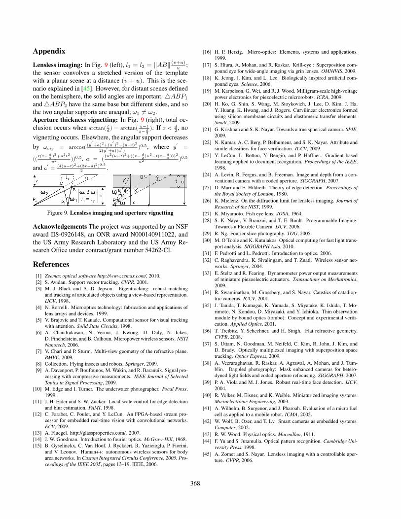
Lensless imaging: In Fig. 9 (left), l1 = l2 = ‖AB‖ (v+u)u ;
the sensor convolves a stretched version of the templatewith a planar scene at a distance (v + u). This is the sce-nario explained in [45]. However, for distant scenes definedon the hemisphere, the solid angles are important. 4ABP1
and4ABP2 have the same base but different sides, and sothe two angular supports are unequal; ω1 6= ω2.Aperture thickness vignetting: In Fig. 9 (right), total oc-clusion occurs when arctan( t
d) = arctan( u−t
x− d2
). If x < d2, no
vignetting occurs. Elsewhere, the angular support decreasesby ωvig = arccos(
(y′+a)2+(a
′)2−(u−t)2
2(y′+a)(a
′)
)0.5, where y′
=
((t(x− d
2)2+u2t2
u2 ))0.5, a = ((u2(u−t)2+((x− d
2)u2−t(x− d
2)))2
u2 )0.5
and a′=
(4(u−t)2+(2x−d)2)0.5
2.
Figure 9. Lensless imaging and aperture vignetting
Acknowledgements The project was supported by an NSFaward IIS-0926148, an ONR award N000140911022, andthe US Army Research Laboratory and the US Army Re-search Office under contract/grant number 54262-CI.
References[1] Zeemax optical software http://www.zemax.com/, 2010.[2] S. Avidan. Support vector tracking. CVPR, 2001.[3] M. J. Black and A. D. Jepson. Eigentracking: robust matching
and tracking of articulated objects using a view-based representation.IJCV, 1998.
[4] N. Borrelli. Microoptics technology: fabrication and applications oflens arrays and devices. 1999.
[5] V. Brajovic and T. Kanade. Computational sensor for visual trackingwith attention. Solid State Circuits, 1998.
[6] A. Chandrakasan, N. Verma, J. Kwong, D. Daly, N. Ickes,D. Finchelstein, and B. Calhoun. Micropower wireless sensors. NSTINanotech, 2006.
[7] V. Chari and P. Sturm. Multi-view geometry of the refractive plane.BMVC, 2009.
[8] Collection. Flying insects and robots. Springer, 2009.[9] A. Davenport, P. Boufounos, M. Wakin, and R. Baranuik. Signal pro-
cessing with compressive measurements. IEEE Journal of SelectedTopics in Signal Processing, 2009.
[10] M. Edge and I. Turner. The underwater photographer. Focal Press,1999.
[11] J. H. Elder and S. W. Zucker. Local scale control for edge detectionand blur estimation. PAMI, 1998.
[12] C. Farabet, C. Poulet, and Y. LeCun. An FPGA-based stream pro-cessor for embedded real-time vision with convolutional networks.ECV, 2009.
[13] A. Fluegel. http://glassproperties.com/. 2007.[14] J. W. Goodman. Introduction to fourier optics. McGraw-Hill, 1968.[15] B. Gyselinckx, C. Van Hoof, J. Ryckaert, R. Yazicioglu, P. Fiorini,
and V. Leonov. Human++: autonomous wireless sensors for bodyarea networks. In Custom Integrated Circuits Conference, 2005. Pro-ceedings of the IEEE 2005, pages 13–19. IEEE, 2006.
[16] H. P. Herzig. Micro-optics: Elements, systems and applications.1999.
[17] S. Hiura, A. Mohan, and R. Raskar. Krill-eye : Superposition com-pound eye for wide-angle imaging via grin lenses. OMNIVIS, 2009.
[18] K. Jeong, J. Kim, and L. Lee. Biologically inspired artificial com-pound eyes. Science, 2006.
[19] M. Karpelson, G. Wei, and R. J. Wood. Milligram-scale high-voltagepower electronics for piezoelectric microrobots. ICRA, 2009.
[20] H. Ko, G. Shin, S. Wang, M. Stoykovich, J. Lee, D. Kim, J. Ha,Y. Huang, K. Hwang, and J. Rogers. Curvilinear electronics formedusing silicon membrane circuits and elastomeric transfer elements.Small, 2009.
[21] G. Krishnan and S. K. Nayar. Towards a true spherical camera. SPIE,2009.
[22] N. Kumar, A. C. Berg, P. Belhumeur, and S. K. Nayar. Attribute andsimile classifiers for face verification. ICCV, 2009.
[23] Y. LeCun, L. Bottou, Y. Bengio, and P. Haffner. Gradient basedlearning applied to document recognition. Proceedings of the IEEE,1998.
[24] A. Levin, R. Fergus, and B. Freeman. Image and depth from a con-ventional camera with a coded aperture. SIGGRAPH, 2007.
[25] D. Marr and E. Hildreth. Theory of edge detection. Proceedings ofthe Royal Society of London, 1980.
[26] K. Mielenz. On the diffraction limit for lensless imaging. Journal ofResearch of the NIST, 1999.
[27] K. Miyamoto. Fish eye lens. JOSA, 1964.[28] S. K. Nayar, V. Branzoi, and T. E. Boult. Programmable Imaging:
Towards a Flexible Camera. IJCV, 2006.[29] R. Ng. Fourier slice photography. TOG, 2005.[30] M. O’Toole and K. Kutulakos. Optical computing for fast light trans-
port analysis. SIGGRAPH Asia, 2010.[31] F. Pedrotti and L. Pedrotti. Introduction to optics. 2006.[32] C. Raghavendra, K. Sivalingam, and T. Znati. Wireless sensor net-
works. Springer, 2004.[33] E. Steltz and R. Fearing. Dynamometer power output measurements
of miniature piezoelectric actuators. Transactions on Mechatronics,2009.
[34] R. Swaminathan, M. Grossberg, and S. Nayar. Caustics of catadiop-tric cameras. ICCV, 2001.
[35] J. Tanida, T. Kumagai, K. Yamada, S. Miyatake, K. Ishida, T. Mo-rimoto, N. Kondou, D. Miyazaki, and Y. Ichioka. Thin observationmodule by bound optics (tombo): Concept and experimental verifi-cation. Applied Optics, 2001.
[36] T. Treibitz, Y. Schechner, and H. Singh. Flat refractive geometry.CVPR, 2008.
[37] S. Uttam, N. Goodman, M. Neifeld, C. Kim, R. John, J. Kim, andD. Brady. Optically multiplexed imaging with superposition spacetracking. Optics Express, 2009.
[38] A. Veeraraghavan, R. Raskar, A. Agrawal, A. Mohan, and J. Tum-blin. Dappled photography: Mask enhanced cameras for hetero-dyned light fields and coded aperture refocusing. SIGGRAPH, 2007.
[39] P. A. Viola and M. J. Jones. Robust real-time face detection. IJCV,2004.
[40] R. Volker, M. Eisner, and K. Weible. Miniaturized imaging systems.Microelectronic Engineering, 2003.
[41] A. Wilhelm, B. Surgenor, and J. Pharoah. Evaluation of a micro fuelcell as applied to a mobile robot. ICMA, 2005.
[42] W. Wolf, B. Ozer, and T. Lv. Smart cameras as embedded systems.Computer, 2002.
[43] R. W. Wood. Physical optics. Macmillan, 1911.[44] F. Yu and S. Jutamulia. Optical pattern recognition. Cambridge Uni-
versity Press, 1998.[45] A. Zomet and S. Nayar. Lensless imaging with a controllable aper-
ture. CVPR, 2006.
368